
Powertrain Management - V6 Engine Page 6C1–1
28–FEB–2003 Page 6C1–1
Section 6C1
Powertrain Management - V6 Engine
ATTENTION
Before performing any Service Operation or other procedure described in this Section, refer to Section 00
CAUTIONS AND NOTES for correct workshop practices with regard to safety and/or property damage.
1 General Information............................................................................................................................... 3
2 Diagnosis................................................................................................................................................ 4
3 Diagnostic Tables.................................................................................................................................. 5
3.1 PCM Wiring Diagrams............................................................................................................................................5
3.2 Table A-6.3 V6 PCM – Heated Oxygen Sensor Check.........................................................................................7
Circuit Description.................................................................................................................................................7
Test Description.....................................................................................................................................................7
Table A-6.3 V6 PCM – Heated Oxygen Sensor Check.......................................................................................8
3.3 Table A-6.3A V6 PCM Engine – Heated Oxygen Sensor Heater Check .............................................................9
Circuit Description.................................................................................................................................................9
Test Description:....................................................................................................................................................9
Table A-6.3A V6 PCM Engine – Heated Oxygen Sensor Heater Check ..........................................................10
3.4 DTC P0131 V6 PCM - Right-hand Heated Oxygen Sensor (O2S) Signal Voltage Low....................................11
Circuit Description...............................................................................................................................................11
Conditions for Running the DTC.........................................................................................................................11
Conditions for Setting the DTC...........................................................................................................................11
Action Taken When the DTC Sets.......................................................................................................................11
Conditions for Clearing the MIL/DTC..................................................................................................................11
Diagnostic Aids....................................................................................................................................................11
Test Description...................................................................................................................................................12
DTC P0131 V6 PCM - Right-hand Heated Oxygen Sensor (02S) Signal Voltage Low.....................................13
3.5 DTC P0132 V6 PCM - Right-hand Heated Oxygen Sensor (O2S) Signal Voltage High...................................14
Circuit Description...............................................................................................................................................14
Conditions for Running the DTC.........................................................................................................................14
Conditions for Setting the DTC...........................................................................................................................14
Action Taken When the DTC Sets.......................................................................................................................14
Conditions for Clearing the MIL/DTC..................................................................................................................14
Diagnostic Aids....................................................................................................................................................14
Test Description...................................................................................................................................................15
DTC P0132 V6 PCM - Right-hand Heated Oxygen Sensor (O2S) Signal Voltage High...................................16
3.6 DTC P0134 V6 PCM - No Right-hand Heated Oxygen Sensor (O2S) Signal....................................................18
Circuit Description...............................................................................................................................................18
Conditions for Running the DTC.........................................................................................................................18
Conditions for Setting the DTC...........................................................................................................................18
Action Taken When the DTC Sets.......................................................................................................................18
Conditions for Clearing the MIL/DTC..................................................................................................................18
Diagnostic Aids....................................................................................................................................................19
Test Description...................................................................................................................................................19
DTC P0134 V6 PCM - No Right-hand Heated Oxygen Sensor (O2S) Signal...................................................20
3.7 DTC P0151 V6 PCM - Left-hand Heated Oxygen Sensor (O2S) Signal Voltage Low ......................................22
Circuit Description...............................................................................................................................................22
Conditions for Running the DTC.........................................................................................................................22
Conditions for Setting the DTC...........................................................................................................................22
Action Taken When the DTC Sets.......................................................................................................................22
Techline

Powertrain Management - V6 Engine Page 6C1–2
28–FEB–2003 Page 6C1–2
Conditions for Clearing the MIL/DTC..................................................................................................................22
Diagnostic Aids....................................................................................................................................................22
Test Description...................................................................................................................................................23
DTC P0151 V6 PCM - Left-hand Heated Oxygen Sensor (02S) Signal Voltage Low.......................................24
3.8 DTC P0152 V6 PCM - Left-hand Heated Oxygen Sensor (O2S) Signal Voltage High......................................25
Circuit Description...............................................................................................................................................25
Conditions for Running the DTC.........................................................................................................................25
Conditions for Setting the DTC...........................................................................................................................25
Action Taken When the DTC Sets.......................................................................................................................25
Conditions for Clearing the MIL/DTC..................................................................................................................25
Diagnostic Aids....................................................................................................................................................25
Test Description...................................................................................................................................................26
DTC P0152 V6 PCM - Left-hand Heated Oxygen Sensor (O2S) Signal Voltage High.....................................27
3.9 DTC P0154 V6 PCM - No Left-hand Heated Oxygen Sensor (O2S) Signal.......................................................29
Circuit Description...............................................................................................................................................29
Conditions for Running the DTC.........................................................................................................................29
Conditions for Setting the DTC...........................................................................................................................29
Action Taken When the DTC Sets.......................................................................................................................29
Conditions for Clearing the MIL/DTC..................................................................................................................29
Diagnostic Aids....................................................................................................................................................30
Test Description...................................................................................................................................................30
DTC P0154 V6 PCM - No Left-hand Oxygen Sensor (O2S) Signal..................................................................31
4 Symptoms............................................................................................................................................. 33
5 Functional Checks............................................................................................................................... 34
6 Service Operations.............................................................................................................................. 35
6.1 Oxygen Sensor.....................................................................................................................................................35
7 Specifications....................................................................................................................................... 36
8 Torque Wrench Specifications................................................................................................... ........ 37
9 Special Tools........................................................................................................................................ 38

Powertrain Management - V6 Engine Page 6C1–3
28–FEB–2003 Page 6C1–3
1 General Information
With the following exceptions, MY 2004 WK Series V6 engine powertrain management system General Information
carries over from MY 2003 VY Series vehicles. For information not contained in this Section, refer to Section 6C1-1,
Powertrain Management - V6 Engine: General Information in the MY 2003 VY and V2 Series Service Information.
• All MY 2004 WK Series vehicles are fitted with new four wire (heated) oxygen sensors.

Powertrain Management - V6 Engine Page 6C1–4
28–FEB–2003 Page 6C1–4
2 Diagnosis
MY 2004 WK Series V6 engine powertrain management system diagnosis information carries over from MY 2003 VY
Series vehicles. For V6 engine powertrain management system diagnosis information, refer to Section 6C1-2, Powertrain
Management - V6 Engine: Diagnosis in the MY 2003 VY and V2 Series Service Information.

Powertrain Management - V6 Engine Page 6C1–5
28–FEB–2003 Page 6C1–5
3 Diagnostic Tables
With the following exceptions, MY 2004 WK Series V6 engine powertrain management system diagnostic tables carry
over from MY 2003 VY Series vehicles. For information not contained in this Section, refer to Sect ion 6C1-2A, P ow ertrain
Management - V6 Engine: Diagnostic Tables in the MY 2003 VY and V2 Series Service Information.
• All MY 2004 WK Series vehicles are fitted with new four wire (heated) oxygen sensors.
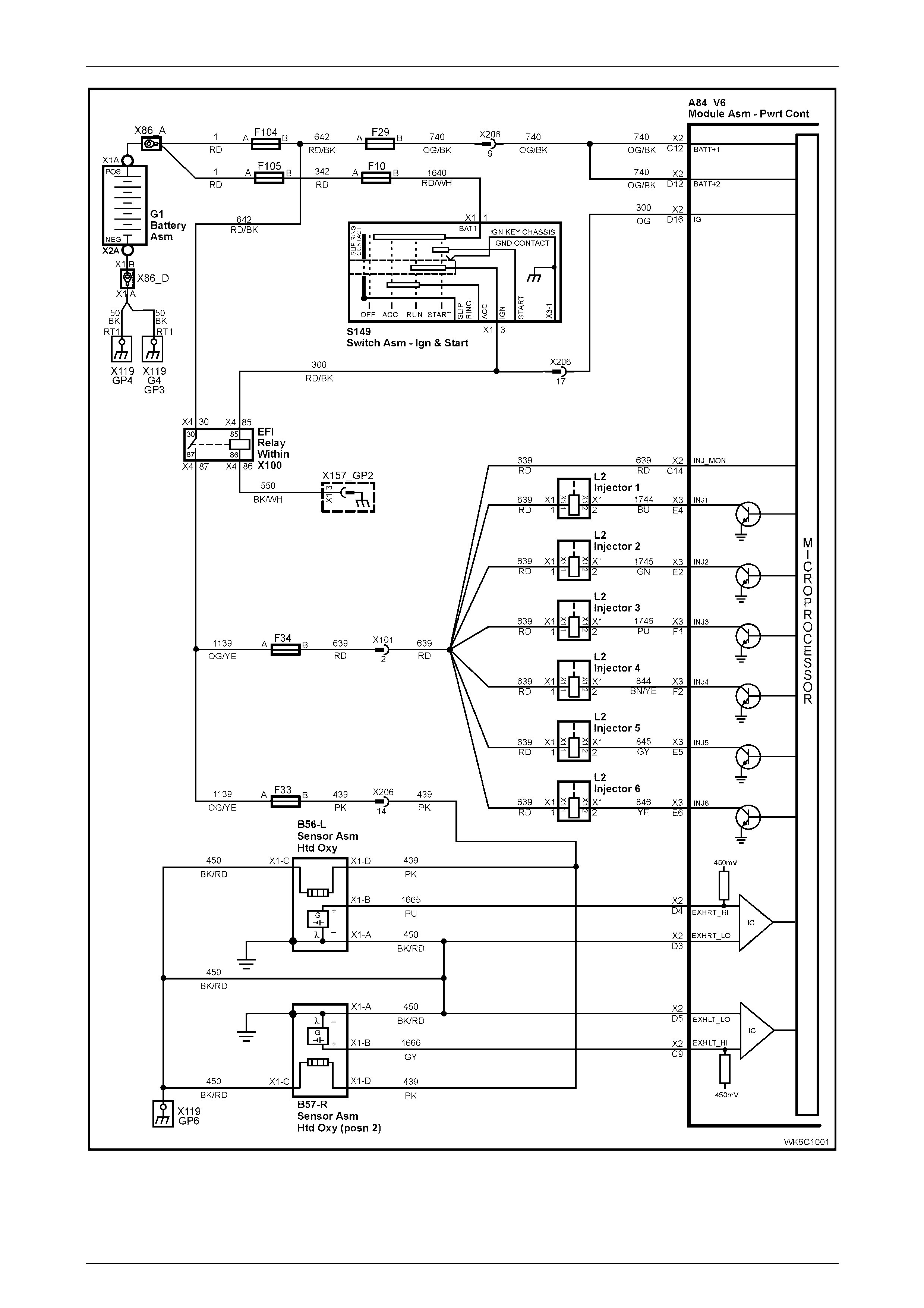
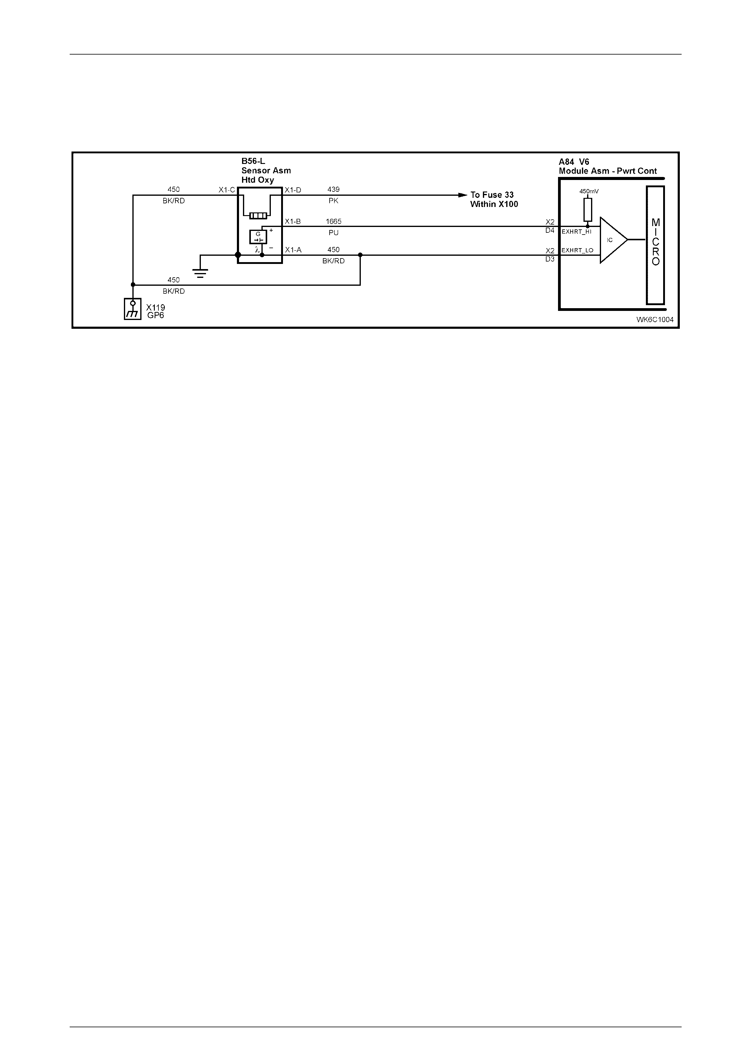
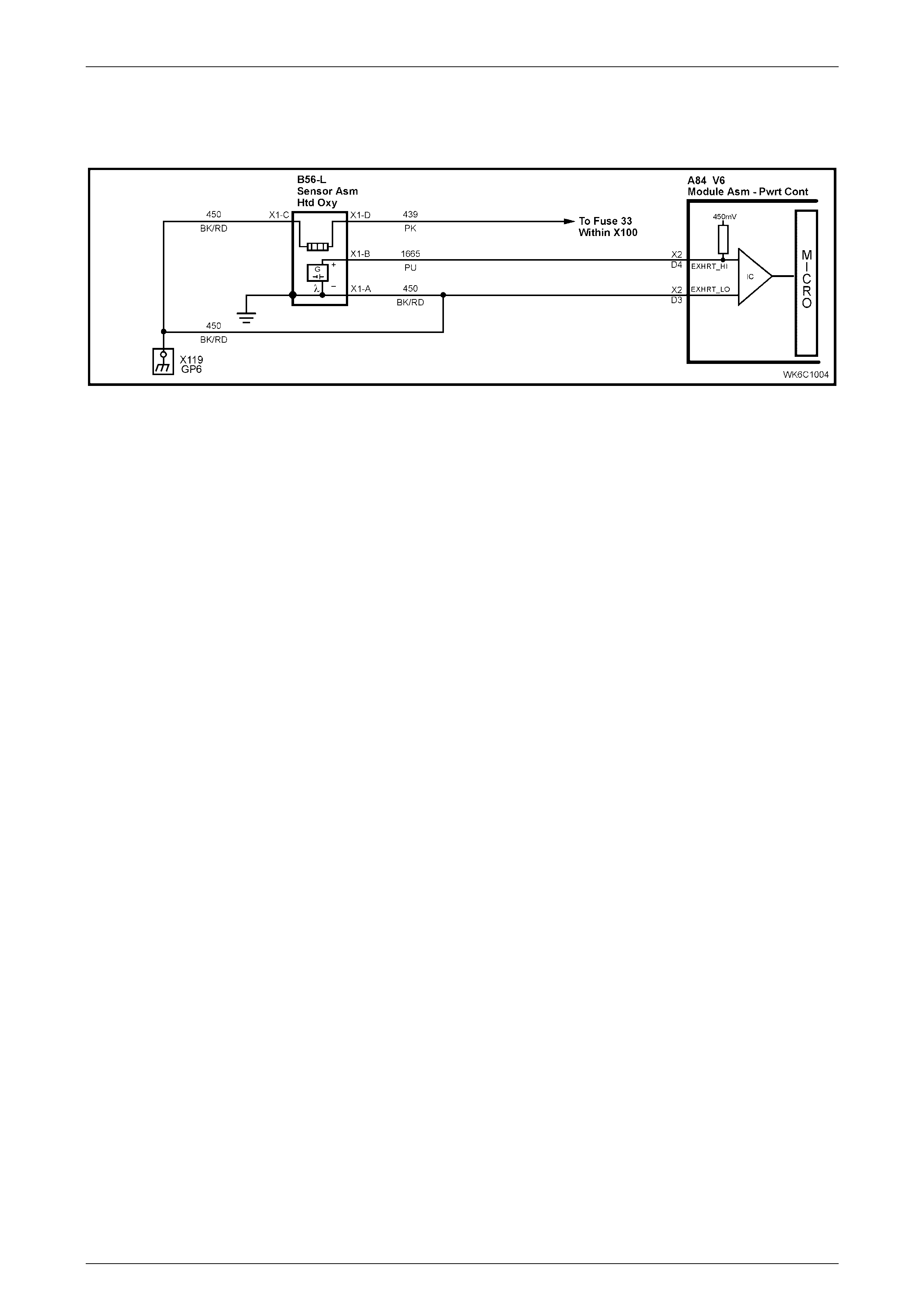
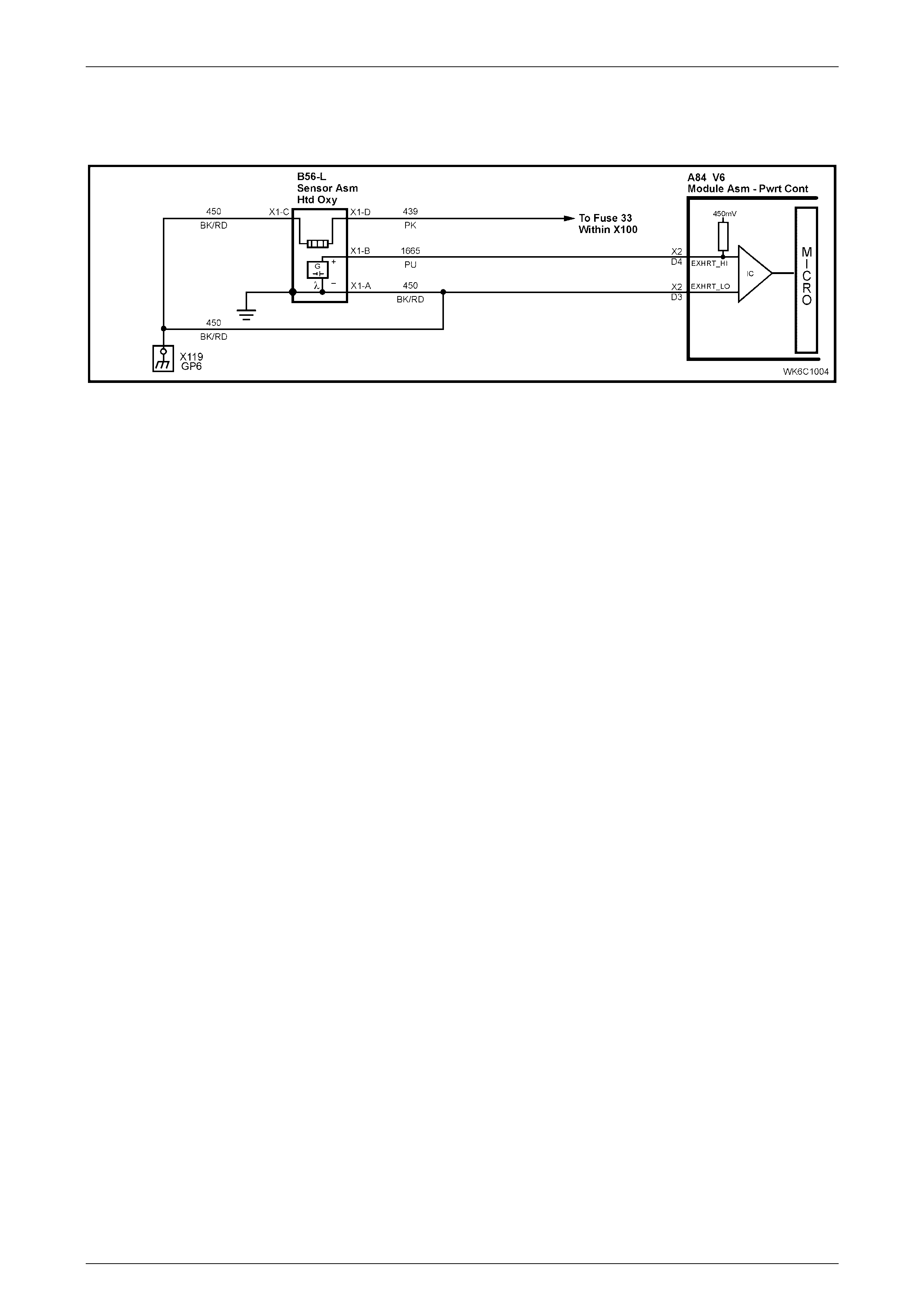
3.1 PCM Wiring Diagrams
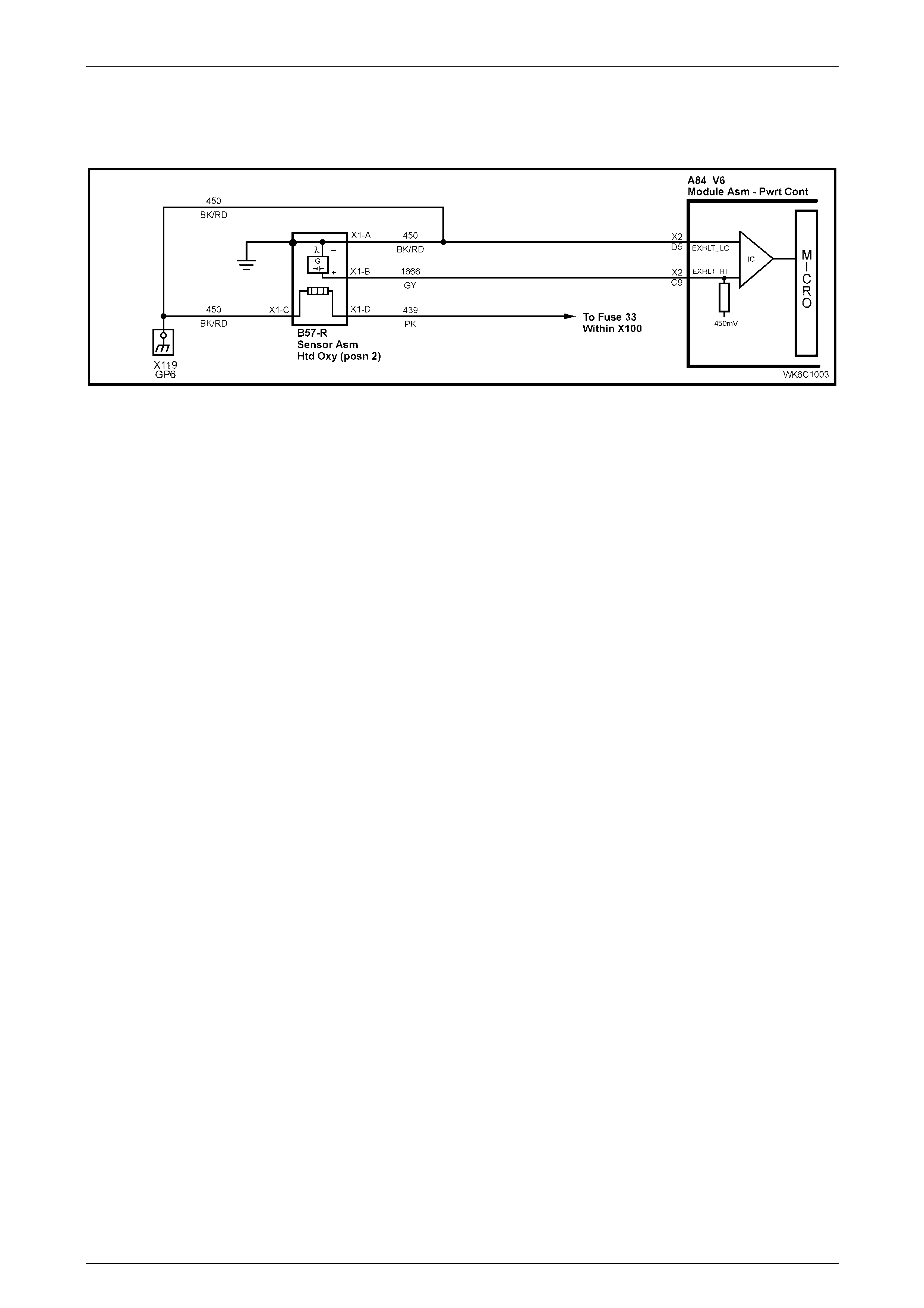
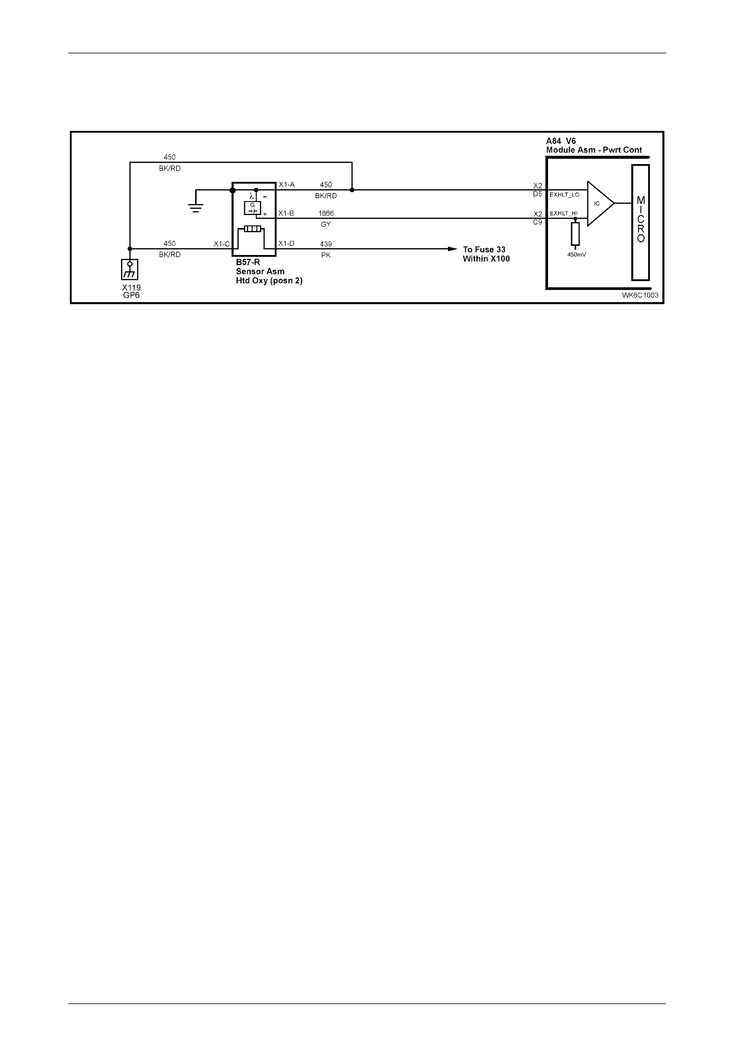
The wiring diagram provided below (Figure 6C1-1) shows the revised oxygen sensor portion of the PCM wiring diagram
for MY 2004 WK Series vehicles. This diagram must be used in conjunction with the remaining diagrams in Section 6C1-
2A, Powertrain Management - V6 Engine: Diagnostic Tables in the MY 2003 VY and V2 Series Service Information for
MY 2004 WK Series left-hand drive vehicles.
NOTE
Apart from the wiring diagrams provided below,
the PCM wiring diagrams for MY 2004 WK Series
vehicles carry over from those provided in
Section 6C1-2A, Powertrain Management - V6
Engine: Diagnostic Tables in the VY and V2
Series Service Information.
Powertrain Management - V6 Engine Page 6C1–6
28–FEB–2003 Page 6C1–6
Figure 6C1-1 –V6 PCM Wiring Diagram – Heated Oxygen Sensors
Powertrain Management - V6 Engine Page 6C1–7
28–FEB–2003 Page 6C1–7
3.2 Table A-6.3 V6 PCM – Heated Oxygen
Sensor Check
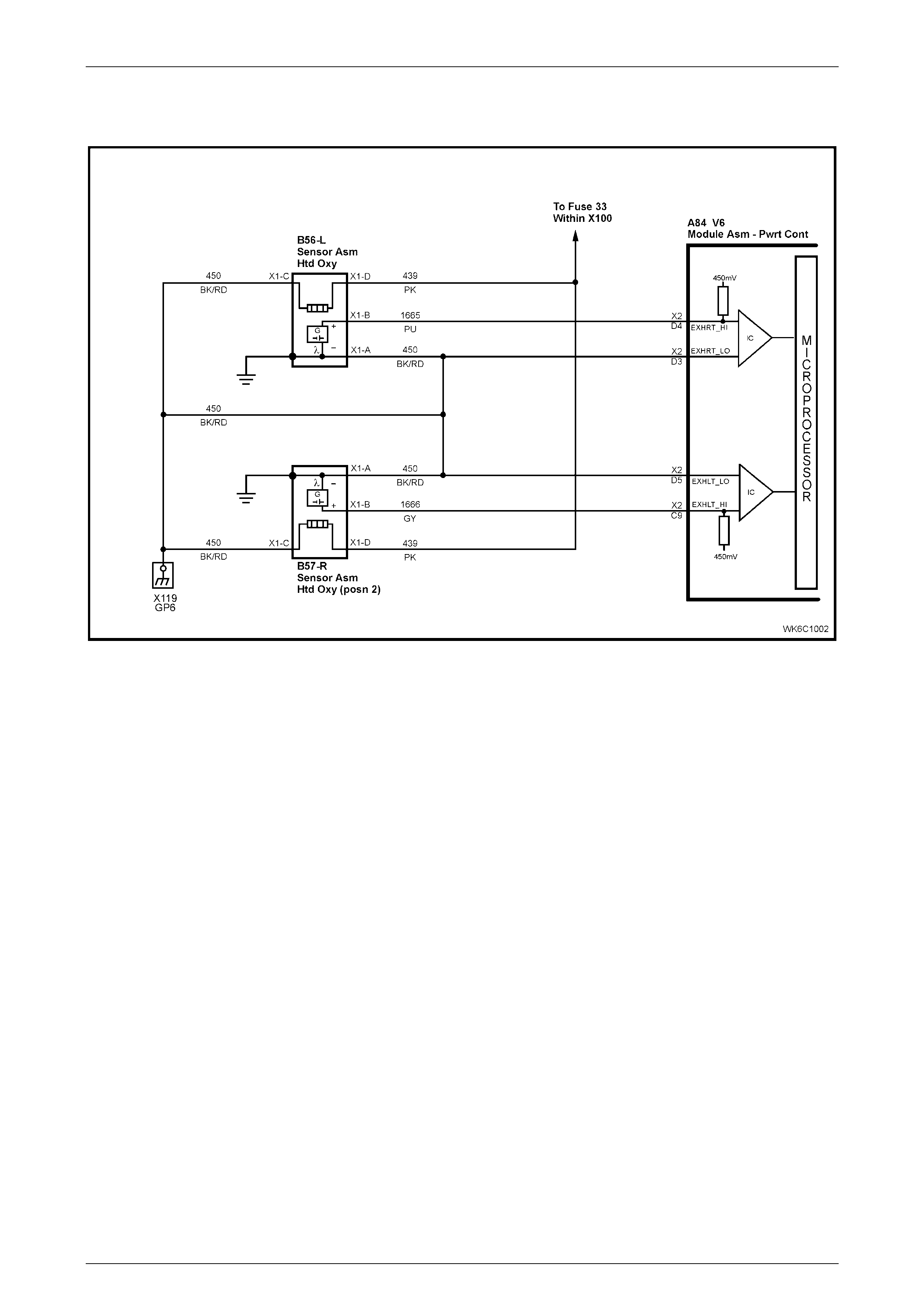
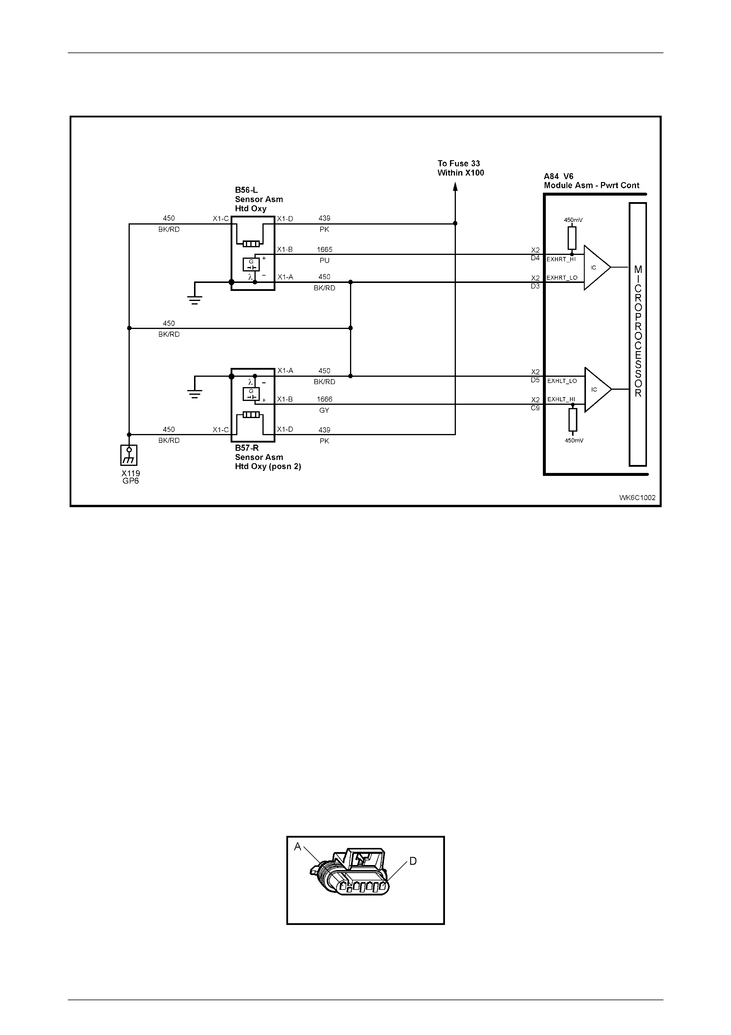
Figure 6C1-2 – Heated Oxygen Sensor Circuit
Circuit Description
The oxygen sensors are mounted in the exhaust pipes near the cylinders. At operating temperature, the oxygen sensors
are required to respond quickly to changes to oxygen content in the exhaust. If the oxygen sensors become
contaminated or faulty, a sluggish driveability or a complaint of poor idle condition may exist. A proper oxygen sensor
response should be almost instantaneous to the fuelling mode command.
Test Description
Number(s) below refer to step number(s) on the Diagnostic Table.
2. Never perform this test on a cold engine. The oxygen sensor must be near normal operating temperature for this
Table to work. It is important to see a low voltage and a high voltage response very quickly because this means the
oxygen sensor is not cont am in ated or faulty .

Powertrain Management - V6 Engine Page 6C1–8
28–FEB–2003 Page 6C1–8
Table A-6.3 V6 PCM – Heated Oxygen Sensor Check
Step Action Value(s) Yes No
1 Was the "On-Board Diagnostic" (OBD) System Check
performed? Go to Step 2 Perform the OBD
System Check,
refer to
Section 6C1-2A,
Table A V6 PCM –
On-Board
Diagnostic (OBD)
System Check
in the VY and V2
Series Service
Information.
2 1. Ignition "ON", engine Running.
2. Run engine at 1600 to 1800 RPM for two minutes,
or until engine temperature is above 85°C, then let
engine idle.
3. Using TECH 2, select Miscellaneous Test / A/F
Ratio, then display RH O2 Sensor and LH O2
Sensor.
4. With engine idling, press the Decrease Soft Key on
TECH 2 until 11.7 A/F Ratio is displayed, at the
same time note the response of both O2 Sensors.
5. Both O2 Sensors should display above specified
value.
6. Then press the Increase Soft Key on TECH 2 until
17.7 A/F Ratio is displayed, at the same time note
the response of both O2 Sensors.
7. Both O2 Sensors should display below specified
value.
Did both O2 Sensors display above and below the
specified value?
Above
700mV or,
below
100mV
No trouble found. Replace the O2
Sensor that did not
perform as
specified. Refer to
Section 6C1-3, 2.6
Oxygen Sensor in
the MY 2003 VY
and V2 Series
Service Information.
Verify Repair.
Powertrain Management - V6 Engine Page 6C1–9
28–FEB–2003 Page 6C1–9
3.3 Table A-6.3A V6 PCM Engine – Heated
Oxygen Sensor Heater Check
Figure 6C1-3 – Heated Oxygen Sensors
Circuit Description
On the V6 engine, two heated oxygen sensors are used to minimise the amount of time required for closed loop fuel
control operation and to allow accurate exhaust converter operation. The oxygen sensor heater greatly decreases the
amount of time required for the oxygen sensor signal to become active, and the PCM to use this signal for efficient
emissions control.
Because the sensor mu st be at least 360° C to operate effectively, it is equipped with an internal electric heating element
to quickly heat the sensor after key "ON", or start up. This heating element is powered from the vehicles electrical
system, any time the ignition is "ON".
The heater is used to maintain the oxygen sensor at a sufficiently high temperature. This allows accurate exhaust oxygen
content readings further from the engine, and maintains the sensors temperature at long engine idle intervals.
Test Description:
Number(s) below refer to step number(s) on the Diagnostic Table.
2. Never perform this test on a cold engine. The oxygen sensor must be near normal operating temperature for this
Table to work. You may not see the voltage at 450 mV when the ignition is cycled "ON", because the Tech 2 scan
tool menus take some time, however, it is important to see a low voltage because this means the oxygen sensor is
only monitoring oxygen in the exhaust pipe.
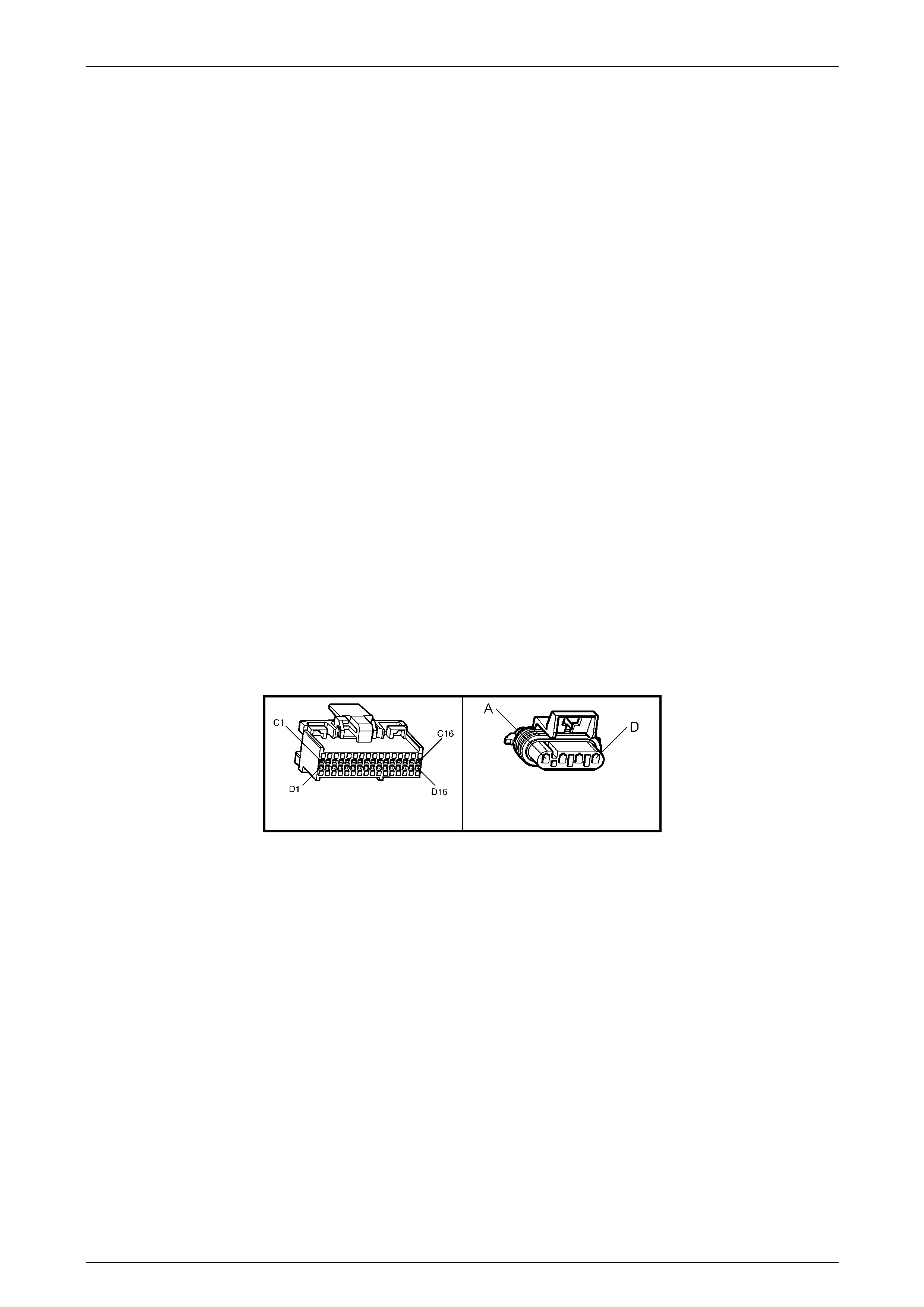
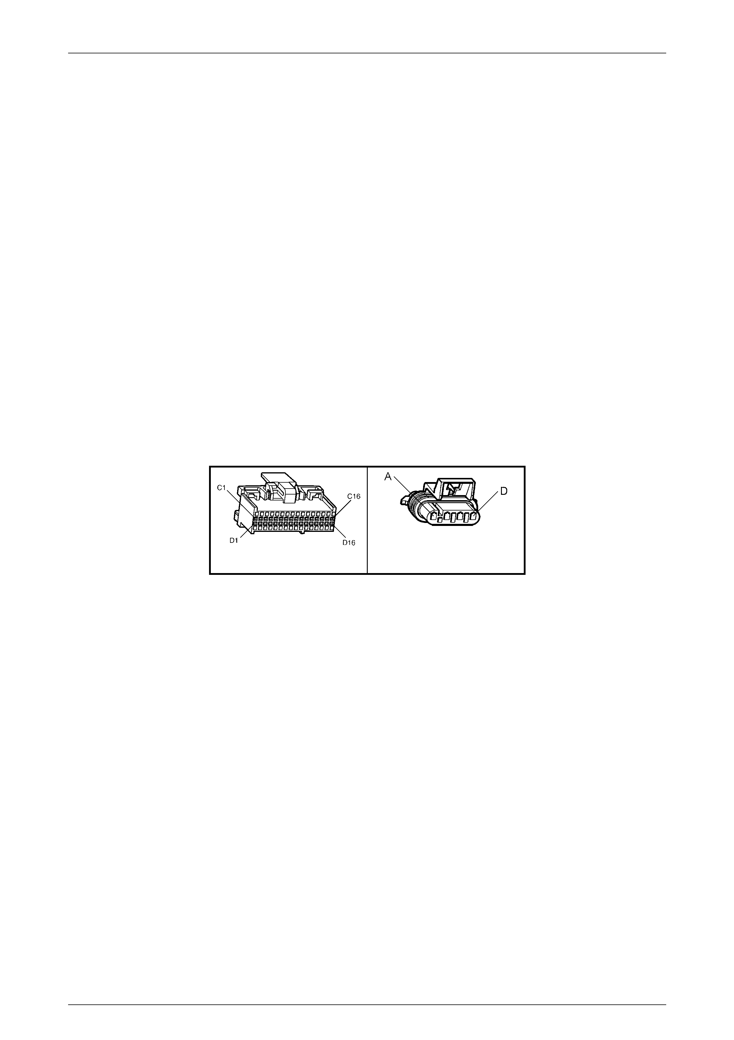
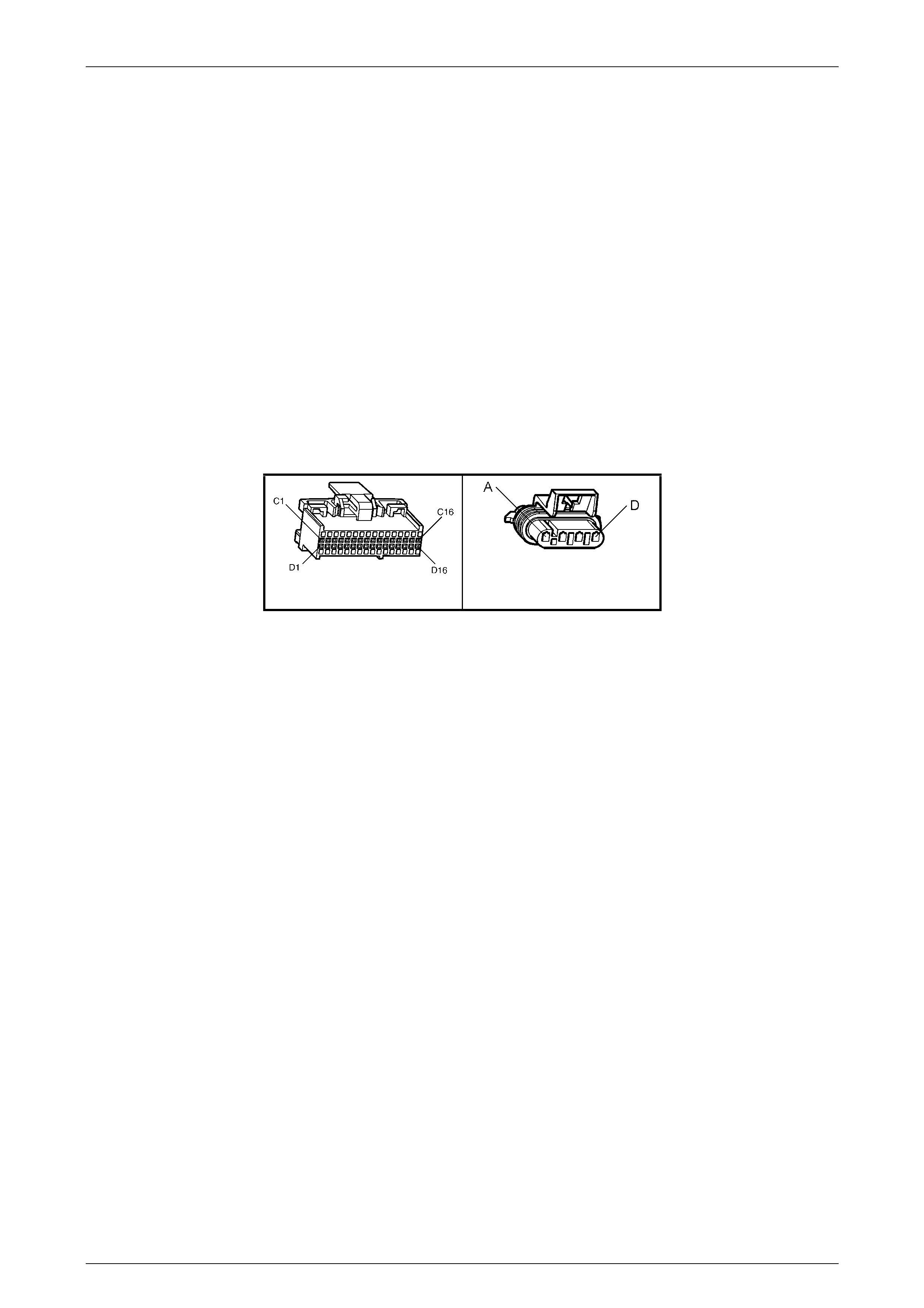
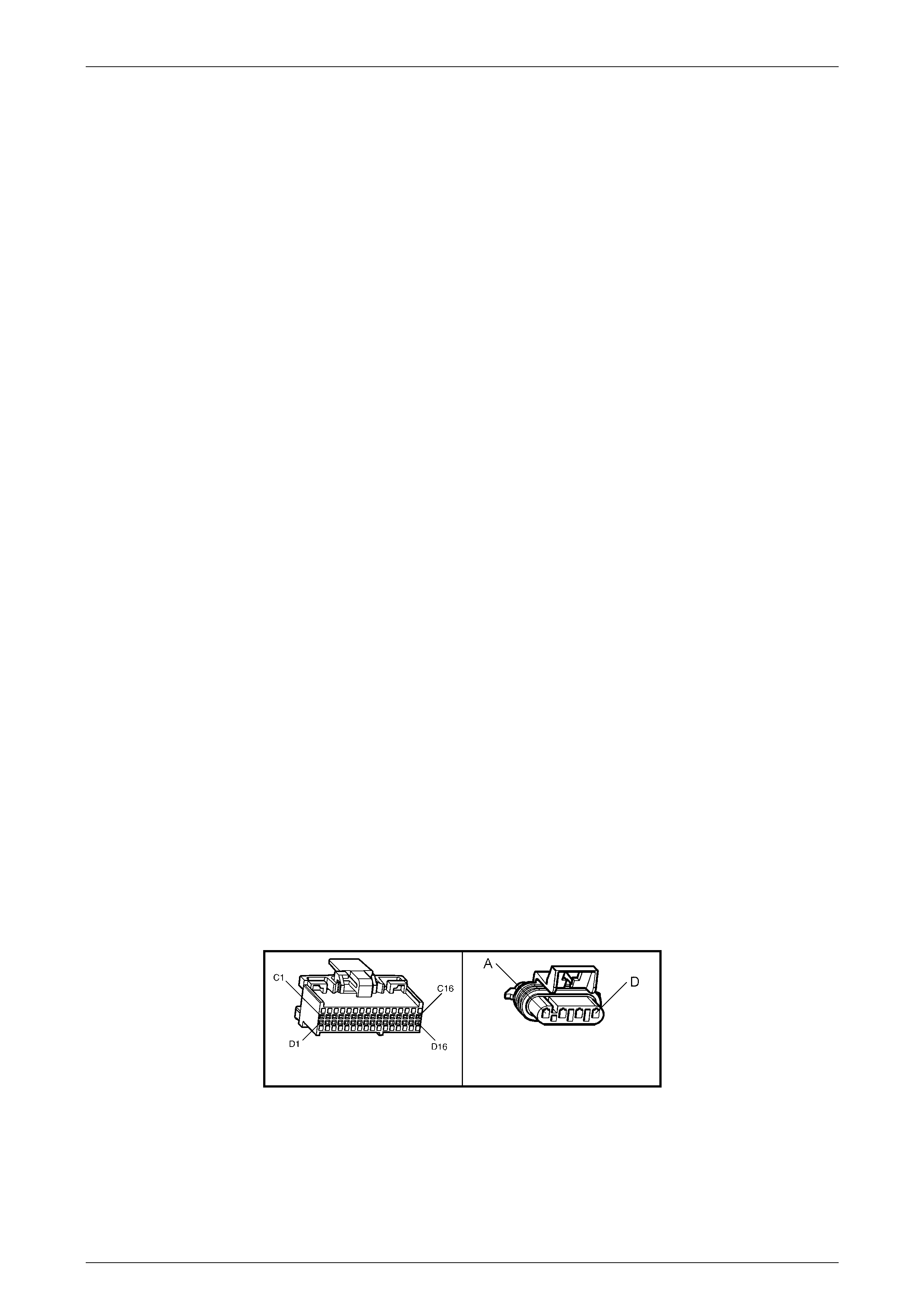
B56 Right/B57 Left
Figure 6C1-4

Powertrain Management - V6 Engine Page 6C1–10
28–FEB–2003 Page 6C1–10
Table A-6.3A V6 PCM Engine – Heated Oxygen Sensor Heater Check
Step Action Value(s) Yes No
1 Was the "On-Board Diagnostic" (OBD) System Check
performed? Go to Step 2. Perform the OBD
System Check,
refer to
Section 6C1-2A,
Table A V6 PCM –
On-Board
Diagnostic (OBD)
System Check
in the VY and V2
Series Service
Information.
2 1. Ignition "ON".
2. Using Tech 2, display LH and RH O2 Sensors.
3. Ignition "ON", engine "OFF".
Did LH and RH O2 Sensor voltages drop to spec ified
value within 60 seconds?
450 mV to
less than 100
mV
No problem found.
Oxygen Sensor
Heater is OK
If both did not drop
to specified value,
repair open or short
to ground in circuit
439 (Pink wire)
between fuse F33
and oxygen sensor.
Replace fuse F33 if
blown and verify
repair.
----------------------
If only one dropped
to specified value,
Go to Step 3.
3 1. Ignition "OFF".
2. Disconnect the oxygen sensor harness
connector from the sensor that did not drop.
3. Connect test light between oxygen sensor
connector on powertrain harness, circuit 439 (Pink) and
ground, circuit 450 (Black/Red wire).
4. Ignition "ON".
Is the test li ght "ON"?
Go to Step 4 Go to Step 5
4 1. Ignition "OFF".
2. Measure resistance of oxygen sensor heater with
ohmmeter between circuits 439 (Pink) and circuit
450 (Black/Red wi re).
Is measured resistance within the specified value?
3.5 - 13.2
ohms Repair poor
connect ion at
oxygen sensor and
verify repair.
Replace the O2
Sensor, refer to
Section 6C1-3, 2.6
Oxygen Sensor in
the MY 2003 VY
and V2 Series
Service Information.
Verify Repair.
5 1. Ignition "OFF".
2. Connect test light to battery positive.
3. Probe oxygen sensor connector on powertrain
harness connec tor, circuit 450 (Black/Red wire).
Is test light "ON"?
Repair open or short
to ground in circuit
439 (Pink) between
fuse F33 and
oxygen sensor.
Replace fuse if
blown and verify
repair.
Repair open in
circuit 450
(Black/Red wire)
and verify repair.

Powertrain Management - V6 Engine Page 6C1–11
28–FEB–2003 Page 6C1–11
3.4 DTC P0131 V6 PCM - Right-hand Heated
Oxygen Sensor (O2S) Signal Voltage
Low
Figure 6C1-5 Right-hand Heated Oxygen Sensor Circuit
Circuit Description
The PCM supplies a voltage of about 450 millivolts between terminal X2-C9 and X2-D5. The oxygen (O2S) sensor varies
the voltage within a range of about one volt if the exhaust is rich, down through about 100 millivolts, if exhaust is lean.
The sensor is like an open circuit and produces no voltage when it is below about 360°C. An open sensor circuit or cold
sensor causes "Open Loop" operation.
Conditions for Running the DTC
• No IAT Sensor DTC’s are set.
• IAT Sensor is below 75°C.
• The system is in "Closed Loop”.
• Throttle angle is between 9% and 30%.
Conditions for Setti ng the DTC
• The RH 02S signal voltage remains below 200 millivolts for 46 seconds.
Action Taken When the DTC Sets
• The PCM activates the Check Powertrain MIL when the diagnostic runs and fails.
• The PCM records the operating conditions at the time the diagnostic fails. The PCM stores this inform ation in the
History Da ta.
• Once an 02S DTC is set, and current, the PCM will operate the fuel system in the “Open Loop” mode.
Conditions for Clearing the MIL/DTC
• The PCM turns the Check Powertrain MIL OFF when it sees a valid condition.
• Use a TECH 2 in order to clear the MIL/DTC.
Diagnostic Aids
Using TECH 2, observe the Long Term Fuel Trim values at different RPMs and air flow conditions. TECH 2 also displays
the Long Term Fuel Trim cells, so the Long Term Fuel Trim values can be checked in each of the cells to determine
when the DTC P0131 may have been set. If the conditions for DTC P0131 exist, the Long Term Fuel Trim values will be
around +25%.
Powertrain Management - V6 Engine Page 6C1–12
28–FEB–2003 Page 6C1–12
Test Description
Number(s) below refer to step number(s) on the Diagnostic Table.
4. The DTC P0131 or lean exhaust is most likely caused by one of the following:
• O2 Sensor Wire - Sensor pigtail may be mispositioned and contacting the exhaust manifold.
• Check for intermittent ground in wire between connector and sensor.
• MAF Sensor - A shifted MAF sensor could cause the fuel system to go lean. Refer to Section 6C1-2A, Table
A-6.1 V6 PCM MAF Sensor Output Check in the VY and V2 Series Service Information.
• Lean Injector(s ) - Perform injector balance test, refer to Section 6C1-2C, 2.7 V6 PCM – Injector Balance Test
in the VY and V2 Series Service Information.
• Fuel Contamination - Water, even in small amounts, near the in-tank fuel pump inlet can be delivered to the
injectors. The water causes a lean exhaust and can set a DTC P0131 and/or DTC P0151.
• Fuel Pressure - System will go lean if pressure is too low. It may be necessary to monitor fuel pressure while
driving the vehicle at various road speeds and/or loads to confirm. Refer to Section 6C1-2A, Table A-4.1 Fuel
Pump Electrical Circuit in the VY and V2 Series Service Information.
• Exhaust Leaks - If there is an exhaust leak, the engine can cause outside air to be pulled into the exhaust
and past the sensor. Vacuum or crankcase leaks can also cause a lean condition.
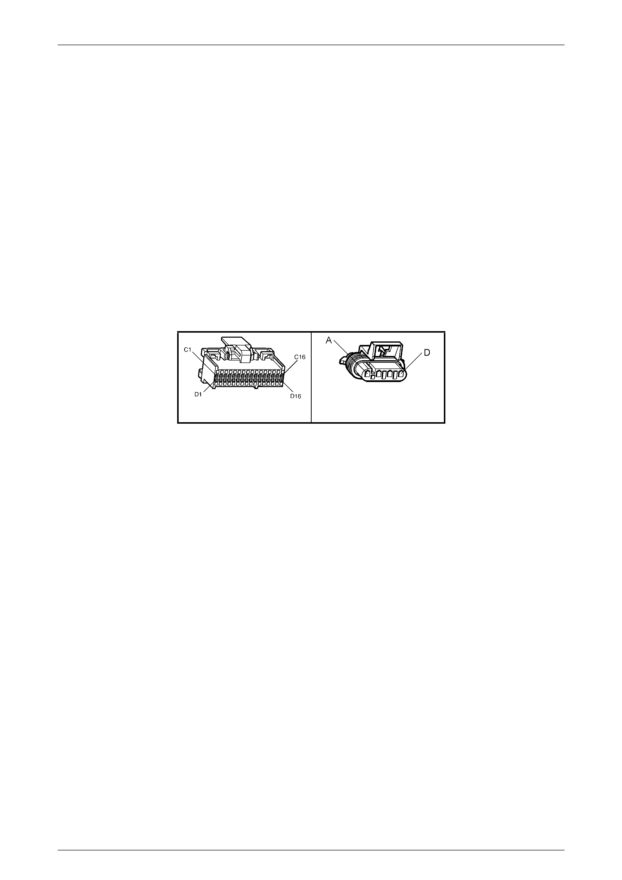
A84 V6 – X2 B57-R
Figure 6C1-6

Powertrain Management - V6 Engine Page 6C1–13
28–FEB–2003 Page 6C1–13
DTC P0131 V6 PCM - Right-hand Heated Oxygen Sensor (02S) Signal Voltage Low
Step Action Value(s) Yes No
1 Was the "On-Board Diagnostic" (OBD) System Check
performed? Go to Step 2 Perform the OBD
System Check,
refer to
Section 6C1-2A,
Table A V6 PCM –
On-Board
Diagnostic (OBD)
System Check
in the VY and V2
Series Service
Information.
2 1. Start engine.
2. Run engine until it reaches normal operating
temperature (Above 80°C).
3. Continue to run at 1600 to 1800 RPM for two
minutes.
Does TECH 2 indicate O2 sensor voltage fixed below
specified value?
200 mV Go to Step 3 DTC P0131 is
intermittent. If no
additional DTCs
were stored, refer to
"Intermitt ent s" in
Section 6C1-2B
SYMPTOMS
in the VY and V2
Series Service
Information.
3 Disconne ct O2 sen sor connector.
With engine idling, does TECH 2 display O2 sensor
voltage between the specified values?
Between
350mV and
550mV
Go to Step 4 Go to Step 5
4 1. Refer to step 4 Te st Description first.
2. Perform the chec ks on the following items as
noted.
• MAF sensor operation
• Low fuel pressure
• Contaminated fuel
• Exhaust manifold leaks ahead of O2 sensor
• Lean injector (possibly restricted)
Are all items checked found to be OK?
Replace the O2
Sensor that did not
perform as specified
in Step 2. Refer to
Section 6C1-3, 2.6
Oxygen Sensor
in the MY 2003 VY
and V2 Series
Service Information.
Verify Repair.
Verify Repair
5 1. Ignition "OFF".
2. Disconnect PCM connectors.
3. With O2 sen sor sti ll dis con nec ted, che ck O2
signal circuit 1666 for a short to ground.
Is a short to ground detected?
Repair short to
ground in circuit
1666 (Grey wire).
Verify repair.
Replace PCM.
Refer to
Section 6C1-3
Service Operations
in the VY and V2
Series Service
Information, for
PCM Programming
and Security Link
procedure.
Verify repair.
Powertrain Management - V6 Engine Page 6C1–14
28–FEB–2003 Page 6C1–14
3.5 DTC P0132 V6 PCM - Right-hand Heated
Oxygen Sensor (O2S) Signal Voltage
High
Figure 6C1-7 Right-hand Heated Oxygen Sensor Circuit
Circuit Description
The PCM supplies a voltage of about 450 millivolts between terminal X2-C9 and X2-D5. The Oxygen (O2) sensor varies
the voltage within a range of about one volt, if the exhaust is rich and down through about 100 millivolts if exhaust is lean.
The sensor produces no voltage when it is below about 360°C. An open sensor circuit or cold sensor causes "Open
Loop" operation.
Conditions for Running the DTC
• No TP Sensor DTC’s are set.
• The system is in "Closed Loop”.
• Throttle angle is between 9% and 30%.
Conditions for Setti ng the DTC
• The RH 02S signal voltage remains above 780 millivolts for 40 seconds.
Action Taken When the DTC Sets
• The PCM activates the Check Powertrain MIL when the diagnostic runs and fails.
• Once an O2S DTC is set, and current, the PCM will operate the fuel system in the “Open Loop” mode.
Conditions for Clearing the MIL/DTC
• The PCM turns the Check Powertrain MIL OFF when it sees a valid condition.
• Use a TECH 2 in order to clear the MIL/DTC.
Diagnostic Aids
Using TECH 2, observe the Long Term Fuel Trim values at different RPM and air flow conditions. TECH 2 also displays
the Long Term Fuel Trim cells, so the Long Term Fuel Trim values can be checked in each of the cells to determine
when the DTC P0132 may have been set. If the conditions for DTC P0132 exist, the Long Term Fuel Trim values will be
around -22%.
NOTE:
Oxygen Sensor Contamination - If fuel containi ng
lead or silicone is used, or engine repairs using
unapproved RTV gasket sealer are performed,
the sensor may be contaminated. It may send a
"false" rich exhaust indication to the PCM, and
the PCM will attempt to drive the fuel system lean
to compensate. Poor driveability or a Diagnostic
Trouble Code P0131 could result. If this happens,
the sensor will need to be replaced, but every
attempt to locate the source of contamination
should be pursued.
Powertrain Management - V6 Engine Page 6C1–15
28–FEB–2003 Page 6C1–15
Test Description
Number(s) below refer to step number(s) on the Diagnostic Table.
2. The O2 sensor MUST be at operating temperature before checking operation.
3. This step checks for a short to voltage on the O2S signal line.
5. Grounding circuit 1666 causes a low O2S signal voltage. If the PCM and wiring are OK, the PCM should recognise
the low voltage and confirm the lean signal.
6. A DTC P0132 will most likely NOT be caused by a faulty O2 sensor. DTC P0132 indicates a rich exhaust and
diagnosis should begin with the items listed:
• Fuel pressure. System will go rich, if pressure is too high. The PCM can compensate for some increase.
However, if it gets too high, a DTC P0132 may be set. Refer to Section 6C1-2A, TABLE A-4.3 V6 PCM – Fuel
Delivery System in the MY 2003 VY and V2 Series Service Information.
• Rich injector.
• Leaking injector. Refe r to Section 6C1-2A, Table A-4.3 V6 PCM – Fuel Delivery System in the MY 2003 VY
and V2 Series Service Information.
• Check for fuel contaminated oil.
• Short to voltage on circuit 1666 (Grey wire).
• HEI shielding. An open ground circuit 453 (ignition system) may result in EMI, or induced electrical "noise."
The PCM looks at this "noise" as reference pulses. The additional pulses result in a hi gher than actual engine
speed signal. The PCM then delivers too much fuel, causing the system to go rich. Engine tachometer will
also show higher than actual engine speed, which can help in diagnosing this problem.
• Canister purge. Check for fuel saturation. If full of fuel, check canister control and hoses.
• MAF sensor. A shifted MAF sensor could cause the fuel system to go rich.
• Check for leaking fuel pressure regulator diaphragm by checking vacuum line to regulator for fuel.
• TP Sensor. An intermittent TP sensor output will cause the system to go rich, due to a false indication of the
engine accelerating.
A84 V6 – X2 B57-R
Figure 6C1-8

Powertrain Management - V6 Engine Page 6C1–16
28–FEB–2003 Page 6C1–16
DTC P0132 V6 PCM - Right-hand Heated Oxygen Sensor (O2S) Signal Voltage High
Step Action Value(s) Yes No
1 Was the "On-Board Diagnostic" (OBD) System Check
performed? Go to Step 2 Perform the OBD
System Check,
refer to
Section 6C1-2A,
Table A V6 PCM –
On-Board
Diagnostic (OBD)
System Check
in the VY and V2
Series Service
Information.
2 1. Engine at normal operating temperature (above
80°C).
2. Run engine at approximately 1600 RPM to 1800
RPM for two minutes.
Is TECH 2 voltage above specified value?
750 mV Go to Step 3 DTC P0132 is
intermittent.
If no additional
DTC(s) were stored,
refer to
"Intermitt ent s" in
Section 6C1-2B
SYMPTOMS
in the VY and V2
Series Service
Information.
3 1. Ignition "OFF".
2. Disconnect O2 sensor wiring harness connector.
3. With a DMM connected to ground, probe circuit
1666 (Grey wire) at O2 sensor wiring harness
connector.
4. Ignition "ON".
Is voltmeter indicating less than specified value?
500 mV Go to Step 5 Go to Step 4
4 1. Ignition "OFF".
2. Disconnect PCM connectors.
3. Probe circuit 1666 (Grey wire) at O2 sensor wiring
harness connec tor.
4. Ignition "ON".
Is voltmeter indicating voltage below specified value?
350 mV Replace PCM.
Refer to
Section 6C1-3
Service Operations
in the VY and V2
Series Service
Information, for
PCM Programming
and Security Link
procedure.
Verify repair.
Repair short to
voltage in circuit
1666 (Grey wire)
and verify repair.
5 1. Disconnect O2 sensor wiring harness connector.
2. Jump harness connector circuit 1666 (Grey wire)
to ground.
With engine running, does TECH 2 display O2 voltage
below specified value?
350 mV Go to Step 6 Go to Step 7

Powertrain Management - V6 Engine Page 6C1–17
28–FEB–2003 Page 6C1–17
Step Action Value(s) Yes No
6 Refer Test Descriptions to perform additional checks
for:
• High Fuel Pressure
• MAF Sensor Operation
• Leaking Injectors
• Ignition Ground Circuit
• Canister Purge
• Engine Coolant Temperature Sensor Circuit
• Intake Air Temperature Sensor Circuit
• Throttle Position Sensor Operation
Do all additional checks test OK?
Replace the O2
Sensor. Refer to
Section 6C1-3, 2.6
Oxygen Sensor
in the MY 2003 VY
and V2 Series
Service Information.
Verify Repair.
Verify Repair
7 1. Ignition "OFF"
2. Connect PCM connectors.
3. Check O2 sensor ground circuit 450 (Black/Red
wire) for continuity between PCM connector
terminal X2-D5 and engine ground.
Is an "OPEN" circuit indicated?
Repair open in
circuit 450
(Black/red wire) and
verify repair
Go to Step 8.
8 Check PCM ground wire connection at engine. The
connection must be a clean and tight to the engine.
Is connection good?
Replace PCM.
Refer to
Section 6C1-3
Service Operations
in the VY and V2
Series Service
Information, for
PCM Programming
and Security Link
procedure.
Verify repair.
Repair poor ground
wire connection at
engine and verify
repair.
Powertrain Management - V6 Engine Page 6C1–18
28–FEB–2003 Page 6C1–18
3.6 DTC P0134 V6 PCM - No Right-hand
Heated Oxygen Sensor (O2S) Signal
Figure 6C1-9 Right-hand Heated Oxygen Sensor Circuit
Circuit Description
The exhaust gas oxygen sensor is mounted in the exhaust pipe with the sensing portion exposed to exhaust gases. After
the sensor is hot (360°C), it becomes a voltage generator, producing a "changing" voltage. This voltage ranges from
approximately 100 millivolts with a "lean" exhaust, to 900 millivolts with a "rich" exhaust. When the sensor is cold (below
360°C) it acts like an open circuit and produces almost no voltage. The PCM supplies a very small "bias" voltage
between terminals X2-C9 and X2-D5, normally about 450 millivolts. If measured wi th the 10 megaohm digital voltmeter, it
may measure as low as 350 millivolts. When the sensor is hot, it's output overshadows this PCM supplied voltage.
When the fuel system is correctly operating in the closed-loop mode, the sensor output is changing several times per
second, going above and below a mid-point range of 490-500 millivolts at a hot idle. The PCM compares the voltage
between the sensor signal and sensor ground terminals and decides the needed fuel mixture correction. The PCM also
monitors the changing voltage, watching for transitions above and below the mid-point range, to decide when to operate
in the closed-loop mod e. An open circ uit, defe ctive, or conta minat ed sen sor cou ld cau se th e voltag e to stay within a 410-
477 millivolt band for too long, keeping the system in open-loop and setting a DTC P0134.
Conditions for Running the DTC
• Engine run time is longer than four minutes.
• No TP Sensor DTC’s are set.
• The ECT sensor is more than 85°C.
• Throttle angle is more than 15%.
Conditions for Setti ng the DTC
• The RH 02S voltage stays between 410-477 millivolts.
Action Taken When the DTC Sets
• The PCM activates the Check Powertrain MIL when the diagnostic runs and fails.
• The PCM records the operating conditions at the time the diagnostic fails. The PCM stores this inform ation in the
History Da ta.
• Once an 02S DTC is set, and current, the PCM will operate the fuel system in the “Open Loop” mode.
Conditions for Clearing the MIL/DTC
• The PCM turns the Check Powertrain MIL OFF when it sees a valid condition.
• Use a TECH 2 in order to clear the MIL/DTC.
Powertrain Management - V6 Engine Page 6C1–19
28–FEB–2003 Page 6C1–19
Diagnostic Aids
Normal TECH 2 voltage varies between 100 mV to 999 mV while in "Closed Loop". DTC P0134 sets if voltage remains
between 410 and 477 millivolts, but the system will go "Open Loop" before the Check Powertrain MIL is turned "ON".
Refer to "Intermittents" in Section 6C1-2B Symptoms in the VY and V2 Series Service Inform ation. To diagnose the
oxygen sensor, refer to 3.2 Table A-6.3 V6 PCM – Heated Oxygen Sensor Check in this Section.
NOTE
Oxygen Sensor Contamination - If fuel containi ng
lead or silicone is used, or engine repairs using
unapproved RTV gasket sealer are performed,
the sensor may be contaminated. It may send a
"False" rich exhaust indication to the PCM, and
the PCM will attempt to drive the fuel system lean
to compensate. Poor driveability or a Diagnostic
Trouble Code P0134 could result. If this happens,
the sensor will need to be replaced, but every
attempt to locate the source of contamination
should be pursued.
Test Description
Number(s) below refer to step number(s) on the Diagnostic Table.
2. TECH 2 allows you to read the same oxygen sensor voltage the PCM is using for its calculations.
3. This step si mulates a lean exhaust indication to the PCM. If the PCM and wiring are OK, the PCM will see the lean
indication and TECH 2 should display O2S voltage below 200 mV.
A84 V6 – X2 B57-R
Figure 6C1-10

Powertrain Management - V6 Engine Page 6C1–20
28–FEB–2003 Page 6C1–20
DTC P0134 V6 PCM - No Right-hand Heated Oxygen Sensor (O2S) Signal
Step Action Value(s) Yes No
1 Was the "On-Board Diagnostic" (OBD) System Check
performed? Go to Step 2 Perform the OBD
System Check,
refer to
Section 6C1-2A,
Table A V6 PCM –
On-Board
Diagnostic (OBD)
System Check
in the VY and V2
Series Service
Information.
2 1. Engine at normal operating temperature (above
85°C).
2. Run engine at approximately 1600 to 1800 RPM
for two minutes.
Is TECH 2 oxygen sensor voltage between specified
values?
410-477 mV Go to Step 3 If no additional
DTCs were stored,
refer to
“Intermittents” in
Section 6C1-2B
Symptoms
in the VY and V2
Series Service
Information.
3 1. Ignition ON, engine stopped.
2. Disconnect O2S and jumper the O2S signal and
low circuits (PCM side) together.
3. Using TECH 2, monitor O2S voltage.
Is the O2S voltage less than the specified value?
200 mV Go to Step 7 Go to Step 4
4 1. Remove the jumper wire from the O2S signal
circuit 1666.
2. Using a DMM, measure voltage between the O2S
signal circuit (PCM side) and ground.
Does the O2S signal voltage measure near the
specified value?
410-477 mV Go to Step 5 Go to Step 6
5 1. Ignition OFF.
2. Disconnect all PCM connectors.
3. Check resisistance of the O2S low circuit 450
(Black/Red wire) between the PCM harness
connector and the O2S harness connector.
Is the O2S low circuit resistance above the specified
value?
5 ohms Repair open or poor
connect ion in circuit
450 (Black/Red
wire) as necessary
and verify repair.
Go to Step 8
6 1. Ignition OFF.
2. Disconnect all PCM connectors.
3. Check resistance of the O2S signal circuit 1666
(Grey wire) between the PCM harness connector
and the O2S harness connector.
Is the O2S sensor circuit resistance above the spec ified
value?
5 ohms Repair open or poor
connect ion in circuit
1666 (Grey wire) as
necessary and
verify repair.
Go to Step 9

Powertrain Management - V6 Engine Page 6C1–21
28–FEB–2003 Page 6C1–21
Step Action Value(s) Yes No
7 1. Check the following ci rcuits for a poor terminal
connection at the O2S harness connector.
• O2S signal circuit 1666 (Grey wire).
• O2S low circuit 450 (Black/Red wire).
Was a problem found?
Repair poor terminal
connections as
necessary and
verify repair
Replace the O2
Sensor. Refer to
Section 6C1-3, 2.6
Oxygen Sensor
in the MY 2003 VY
and V2 Series
Service Information.
Verify Repair.
8 1. Check for poor O2S low circuit terminal
connection at PCM.
Was a problem found?
Repair poor terminal
connections as
necessary and
verify repair.
Replace PCM.
Refer to
Section 6C1-3
Service Operations
in the VY and V2
Series Service
Information, for
PCM Programming
and Security Link
procedure.
Verify repair.
9 1. Check the O2S signal circuit for a poor terminal
connection at the PCM.
Was a problem found?
Repair poor terminal
connect ion as
necessary and
verify repair.
Replace PCM.
Refer to
Section 6C1-3
Service Operations
in the VY and V2
Series Service
Information, for
PCM Programming
and Security Link
procedure.
Verify repair.
Powertrain Management - V6 Engine Page 6C1–22
28–FEB–2003 Page 6C1–22
3.7 DTC P0151 V6 PCM - Left-hand Heated
Oxygen Sensor (O2S) Signal Voltage
Low
Figure 6C1-11 Left-hand Heated Oxygen Sensor Circuit
Circuit Description
The PCM supplies a voltage of about 450 millivolts between terminal X2-D4 and X2-D3. The oxygen (O2) sensor varies
the voltage within a range of about one volt if the exhaust is rich, down through about 100 millivolts, if exhaust is lean.
The sensor is like an open circuit and produces no voltage when it is below about 360°C. An open sensor circuit or cold
sensor causes "Open Loop" operation.
Conditions for Running the DTC
• No IAT Sensor DTC’s are set.
• IAT Sensor is below 75°C.
• The system is in "Closed Loop”.
• Throttle angle is between 9% and 30%.
Conditions for Setti ng the DTC
• The LH 02S signal voltage remains below 200 millivolts for 46 seconds.
Action Taken When the DTC Sets
• The PCM activates the Check Powertrain MIL when the diagnostic runs and fails.
• The PCM records the operating conditions at the time the diagnostic fails. The PCM stores this inform ation in the
History Da ta.
• Once an 02S DTC is set, and current, the PCM will operate the fuel system in the “Open Loop” mode.
Conditions for Clearing the MIL/DTC
• The PCM turns the Check Powertrain MIL OFF when it sees a valid condition.
• Use a TECH 2 in order to clear the MIL/DTC.
Diagnostic Aids
Using TECH 2, observe the Long Term Fuel Trim values at different RPMs and air flow conditions. TECH 2 also displays
the Long Term Fuel Trim cells, so the Long Term Fuel Trim values can be checked in each of the cells to determine
when the DTC P0151 may have been set. If the conditions for DTC P0151 exist, the Long Term Fuel Trim values will be
around +25%.
Powertrain Management - V6 Engine Page 6C1–23
28–FEB–2003 Page 6C1–23
Test Description
Number(s) below refer to step number(s) on the Diagnostic Table.
4. The DTC P0151 or lean exhaust is most likely caused by one of the following:
• O2 Sensor Wire - Sensor pigtail may be mispositioned and contacting the exhaust manifold.
• Check for intermittent ground in wire between connector and sensor.
• MAF Sensor - A shifted MAF sensor could cause the fuel system to go lean. Refer to Section 6C1-2A, Table
A-6.1V6 PCM MAF Sensor Output Check in the VY and V2 Series Service Information.
• Lean Injector(s ) - Perform injector balance. Refer to Section 6C1-2C, 2.7 V6 PCM – Injector Balanc e Test in
the VY and V2 Series Service Information.
• Fuel Contamination - Water, even in small amounts, near the in-tank Fuel Pump inlet can be delivered to the
injectors. The water causes a lean exhaust and can set a DTC P0151 and/or DTC P0131.
• Fuel Pressure - System will go lean if pressure is too low. It may be necessary to monitor fuel pressure while
driving the vehicle at various road speeds and/or loads to confirm. Refer to Section 6C1-2A, Table A-4.1 Fuel
Pump Electrical Circuit in the VY and V2 Series Service Information.
• Exhaust Leaks - If there is an exhaust leak, the engine can cause outside air to be pulled into the exhaust
and past the sensor. Vacuum or crankcase leaks can also cause a lean condition.
A84 V6 – X2 B56-L
Figure 6C1-12

Powertrain Management - V6 Engine Page 6C1–24
28–FEB–2003 Page 6C1–24
DTC P0151 V6 PCM - Left-hand Heated Oxygen Sensor (02S) Signal Voltage Low
Step Action Value(s) Yes No
1 Was the "On-Board Diagnostic" (OBD) System Check
performed? Go to Step 2 Perform the OBD
System Check,
refer to
Section 6C1-2A,
Table A V6 PCM –
On-Board
Diagnostic (OBD)
System Check
in the VY and V2
Series Service
Information.
2 1. Start engine.
2. Run engine until it reaches normal operating
temperature (Above 80°C).
3. Continue to run at 1600 to 1800 RPM for two
minutes.
Does TECH 2 indicate O2 sensor voltage fixed below
specified value?
200 mV Go to Step 3 DTC P0151 is
intermittent. If no
additional DTCs
were stored, refer to
"Intermitt ent s" in
Section 6C1-2B
Symptoms
in the VY and V2
Series Service
Information.
3 Disconne ct O2 sen sor connector.
With engine idling, does TECH 2 display O2 sensor
voltage between the specified values?
Between
350 mV
and
550 mV
Go to Step 4 Go to Step 5
4 1. Refer to step 4 Te st Description first.
2. Perf orm the ch ecks on the items as noted.
• MAF sensor operation
• Low fuel pressure
• Contaminated fuel
• Exhaust manifold leaks ahead of O2 sensor
• Lean injector (possibly restricted)
Are all items checked found to be OK?
Replace the O2
Sensor. Refer to
Section 6C1-3, 2.6
Oxygen Sensor
in the MY 2003 VY
and V2 Series
Service Information.
Verify Repair.
Verify Repair
5 1. Ignition "OFF".
2. Disconnect PCM connectors.
3. With O2 sensor sti ll dis con nec ted, che ck O2
signal circuit 1665 (Purple wire) for a short to
ground.
Is a short to ground detected?
Repair short to
ground in circuit
1665 (Purple wire)
and verify repair.
Replace PCM.
Refer to
Section 6C1-3
Service Operations
in the VY and V2
Series Service
Information, for
PCM Programming
and Security Link
procedure.
Verify repair.
Powertrain Management - V6 Engine Page 6C1–25
28–FEB–2003 Page 6C1–25
3.8 DTC P0152 V6 PCM - Left-hand Heated
Oxygen Sensor (O2S) Signal Voltage
High
Figure 6C1-13 Left-hand Heated Oxygen Sensor Circuit
Circuit Description
The PCM supplies a voltage of about 450 millivolts between terminal X2-D4 and X2-D3. The oxygen (O2) sensor varies
the voltage within a range of about one volt, if the exhaust is rich and down through about 100 millivolts if exhaust is lean.
The sensor produces no voltage when it is below about 360°C. An open sensor circuit or cold sensor causes "Open
Loop" operation.
Conditions for Running the DTC
• No TP Sensor DTC’s are set.
• The system is in "Closed Loop”.
• Throttle angle is between 9% and 30%.
Conditions for Setti ng the DTC
• The LH 02S signal voltage remains above 780 millivolts for 40 seconds.
Action Taken When the DTC Sets
• The PCM activates the Check Powertrain MIL when the diagnostic runs and fails.
• The PCM records the operating conditions at the time the diagnostic fails. The PCM stores this inform ation in the
History Da ta.
• Once an 02S DTC is set, and current, the PCM will operate the fuel system in the “Open Loop” mode.
Conditions for Clearing the MIL/DTC
• The PCM turns the Check Powertrain MIL OFF when it sees a valid condition.
• Use a TECH 2 in order to clear the MIL/DTC.
Diagnostic Aids
Using TECH 2, observe the Long Term Fuel Trim values at different RPM and air flow conditions. TECH 2 also displays
the Long Term Fuel Trim cells, so the Long Term Fuel Trim values can be checked in each of the cells to determine
when the DTC P0152 may have been set. If the conditions for DTC P0152 exist, the Long Term Fuel Trim values will be
around -22%.
Powertrain Management - V6 Engine Page 6C1–26
28–FEB–2003 Page 6C1–26
NOTE
Oxygen Sensor Contamination - If fuel containi ng
lead or silicone is used, or engine repairs using
unapproved RTV gasket sealer are performed,
the sensor may be contaminated. It may send a
"false" rich exhaust indication to the PCM, and
the PCM will attempt to drive the fuel system lean
to compensate. Poor driveability or a Diagnostic
Trouble Code P0151 could result. If this happens,
the sensor will need to be replaced, but every
attempt to locate the source of contamination
should be pursued.
Test Description
Number(s) below refer to step number(s) on the Diagnostic Table.
2. The O2 sensor MUST be at operating temperature before checking operation.
3. This step checks for a short to voltage on the O2S signal line.
5. Grounding circuit 1665 causes a low O2S signal voltage. If the PCM and wiring are OK, the PCM should recognise
the low voltage and confirm the lean signal.
6. A DTC P0152 will most likely NOT be caused by a faulty O2 sensor. DTC P0152 indicates a rich exhaust and
diagnosis should begin with the items listed:
• Fuel pressure. System will go rich, if pressure is too high. The PCM can compensate for some increase.
However, if it gets too high, a DTC P0152 may be set. Refer to Section 6C1-2A, Table A-4.3 V6 PCM – Fuel
Delivery System in the VY and V2 Series Service Information.
• Rich injector.
• Leaking injector. Refe r to Section 6C1-2A, Table A-4.3 V6 PCM – Fuel Delivery System in the VY and V2
Series Service Information.
• Check for fuel contaminated oil.
• Short to voltage on circuit 1665.
• HEI shielding. An open ground circuit 453 (ignition system) may result in EMI, or induced electrical "noise."
The PCM looks at this "noise" as reference pulses. The additional pulses result in a hi gher than actual engine
speed signal. The PCM then delivers too much fuel, causing the system to go rich. Engine tachometer will
also show higher than actual engine speed, which can help in diagnosing this problem.
• Canister purge. Check for fuel saturation. If full of fuel, check canister control and hoses.
• MAF sensor. A shifted MAF sensor could cause the fuel system to go rich.
• Check for leaking fuel pressure regulator diaphragm by checking vacuum line to regulator for fuel.
• TP Sensor. An intermittent TP sensor output will cause the system to go rich, due to a false indication of the
engine accelerating.
A84 V6 – X2 B56-L
Figure 6C1-14

Powertrain Management - V6 Engine Page 6C1–27
28–FEB–2003 Page 6C1–27
DTC P0152 V6 PCM - Left-hand Heated Oxygen Sensor (O2S) Signal Voltage High
Step Action Value(s) Yes No
1 Was the "On-Board Diagnostic" (OBD) System Check
performed? Go to Step 2 Perform the OBD
System Check,
refer to
Section 6C1-2A,
Table A V6 PCM –
On-Board
Diagnostic (OBD)
System Check
in the VY and V2
Series Service
Information.
2 1. Engine at normal operating temperature (above
80°C).
2. Run engine at approximately 1600 RPM to 1800
RPM for two minutes.
Is TECH 2 voltage above specified value?
750 mV Go to Step 3 DTC P0152 is
intermittent.
If no additional
DTC(s) were stored,
refer to
"Intermitt ent s" in
Section 6C1-2B
SYMPTOMS
in the VY and V2
Series Service
Information.
3 1. Ignition "OFF".
2. Disconnect O2 sensor wiring harness connector.
3. With Digital Multimeter (DMM) connected to
ground, probe circuit 1665 (Purple wire) at O2
sensor wiring harness connector.
4. Ignition "ON".
Is voltmeter indicating less than specified value?
500 mV Go to Step 5 Go to Step 4
4 1. Ignition "OFF".
2. Disconnect PCM connectors.
3. Probe circuit 1665 at O2 sensor wiring harness
connector.
4. Ignition "ON".
Is voltmeter indicating voltage below specified value?
350 mV Replace PCM.
Refer to
Section 6C1-3
Service Operations
in the VY and V2
Series Service
Information, for
PCM Programming
and Security Link
procedure.
Verify repair.
Repair short to
voltage in circuit
1665 (Purple wire)
and verify repair.
5 1. Disconnect O2 sensor wiring harness connector.
2. Jumper harness conne ctor cir cuit 166 5 to ground.
With engine running, does TECH 2 display O2 voltage
below specified value?
350 mV Go to Step 6. Go to Step 7

Powertrain Management - V6 Engine Page 6C1–28
28–FEB–2003 Page 6C1–28
Step Action Value(s) Yes No
6 See step 8 in Test Description to perform additional
checks for:
• High Fuel Pressure
• MAF Sensor Operation
• Leaking Injectors
• Ignition Ground Circuit
• Canister Purge
• Engine Coolant Temperature Sensor Circuit
• Intake Air Temperature Sensor Circuit
• Throttle Position Sensor Operation
Are all items checked found to be OK?
Replace the O2
Sensor. Refer to
Section 6C1-3, 2.6
Oxygen Sensor
in the MY 2003
VY and V2 Series
Service Information.
Verify Repair.
Verify Repair
7 1. Ignition "OFF"
2. Connect PCM connectors.
3. Check O2 sensor ground circuit 450 (Black/Red
wire) for good continuity between PCM connector
terminal X2-D3 and engine ground.
Is an "OPEN" circuit indicated?
Repair open in
circuit 450
(Black/Red wire)
and verify repair.
Go to Step 8
8 Check PCM ground wire connections at engine. Must
be a clean and tight connection to the engine.
Are connections good?
Replace PCM.
Refer to
Section 6C1-3
Service Operations
in the VY and V2
Series Service
Information, for
PCM Programming
and Security Link
procedure.
Verify repair.
Repair poor ground
wire connection at
engine and verify
repair.
Powertrain Management - V6 Engine Page 6C1–29
28–FEB–2003 Page 6C1–29
3.9 DTC P0154 V6 PCM - No Left-hand
Heated Oxygen Sensor (O2S) Signal
Figure 6C1-15 Left-hand Heated Oxygen Sensor Circuit
Circuit Description
The exhaust gas oxygen sensor is mounted in the exhaust pipe with the sensing portion exposed to exhaust gases. After
the sensor is hot (360°C), it becomes a voltage generator, producing a "changing" voltage. This voltage ranges from
approximately 100 millivolts with a "lean" exhaust, to 900 millivolts with a "rich" exhaust. When the sensor is cold (below
360°C) it acts like an open circuit and produces almost no voltage. The PCM supplies a very small "bias" voltage
between terminals X2-D4 and X2-D3, normally about 450 millivolts. If measured wi th the 10 megaohm digital voltmeter, it
may measure as low as 350 millivolts. When the sensor is hot, it's output overshadows this PCM supplied voltage.
When the fuel system is correctly operating in the closed-loop mode, the sensor output is changing several times per
second, going above and below a mid-point range of 490-500 millivolts at a hot idle. The PCM compares the voltage
between the sensor signal and sensor ground terminals and decides the needed fuel mixture correction. The PCM also
monitors the changing voltage, watching for transitions above and below the mid-point range, to decide when to operate
in the closed-loop mod e. An open circ uit, defe ctive, or conta minat ed sen sor cou ld cau se th e voltag e to stay within a 410-
477 millivolt band for too long, keeping the system in open-loop and setting a DTC P0154.
Conditions for Running the DTC
• Engine run time is longer than four minutes.
• No TP Sensor DTC’s are set.
• The ECT sensor is more than 85°C.
• Throttle angle is more than 15%.
Conditions for Setti ng the DTC
• The LH 02S voltage stays between 410-477 millivolts.
Action Taken When the DTC Sets
• The PCM activates the Check Powertrain MIL when the diagnostic runs and fails.
• The PCM records the operating conditions at the time the diagnostic fails. The PCM stores this inform ation in the
History Da ta.
• Once an O2S DTC is set, and current, the PCM will operate the fuel system in the “Open Loop” mode.
Conditions for Clearing the MIL/DTC
• The PCM turns the Check Powertrain MIL OFF when it sees a valid condition.
• Use a TECH 2 in order to clear the MIL/DTC.

Powertrain Management - V6 Engine Page 6C1–30
28–FEB–2003 Page 6C1–30
Diagnostic Aids
Normal TECH 2 voltage varies between 100 mV to 999 mV while in "Closed Loop". DTC P0154 sets if voltage remains
between 410 and 477 millivolts, but the system will go "Open Loop" before the Check Powertrain MIL is turned "ON".
Refer to "Intermittents" in Section 6C1-2B Symptoms in the VY and V2 Series Service Information. To diagnose the
oxygen sensor, refer to 3.2 Table A-6.3 V6 PCM – Heated Oxygen Sensor Check in this Section.
NOTE
Oxygen Sensor Contamination - If fuel containi ng
lead or silicone is used, or engine repairs using
unapproved RTV gasket sealer are performed,
the sensor may be contaminated. It may send a
"False" rich exhaust indication to the PCM, and
the PCM will attempt to drive the fuel system lean
to compensate. Poor driveability or a Diagnostic
Trouble Code P0154 could result. If this happens,
the sensor will need to be replaced, but every
attempt to locate the source of contamination
should be pursued.
Test Description
Number(s) below refer to step number(s) on the Diagnostic Table.
2. TECH 2 allows you to read the same oxygen sensor voltage the PCM is using for its calculations.
3. This step si mulates a lean exhaust indication to the PCM. If the PCM and wiring are OK, the PCM will see the lean
indication and TECH 2 should display O2 voltage below 200 mV.
A84 V6 – X2 B56-L
Figure 6C1-16

Powertrain Management - V6 Engine Page 6C1–31
28–FEB–2003 Page 6C1–31
DTC P0154 V6 PCM - No Left-hand Oxygen Sensor (O2S) Signal
Step Action Value(s) Yes No
1 Was the "On-Board Diagnostic" (OBD) System Check
performed? Go to Step 2 Perform the OBD
System Check,
refer to
Section 6C1-2A,
Table A V6 PCM –
On-Board
Diagnostic (OBD)
System Check
in the VY and V2
Series Service
Information.
2 1. Engine at normal operating temperature (above
85°C).
2. Run engine at approximately 1600 to 1800 RPM
for two minutes.
Is TECH 2 oxygen sensor voltage between specified
values?
410-477 mV Go to Step 3 If no additional
DTCs were stored,
refer to
“Intermittents” in
Section 6C1-2B
Symptoms
in the VY and V2
Series Service
Information.
3 1. Ignition ON, engine stopped.
2. Disconnect O2S and jumper the O2S signal and
low circuits (PCM side) together.
3. Using TECH 2, monitor O2S voltage.
Is the O2S voltage less than the specified value?
200 mV Go to Step 7 Go to Step 4
4 1. Remove the jumper wire from the O2S signal
circuit 1665 (purple wire).
2. Using a DMM, measure voltage between the O2S
signal circuit (PCM side) and ground.
Does the O2S signal voltage measure near the
specified value?
410-477 mV Go to Step 5 Go to Step 6
5 1. Ignition OFF.
2. Disconnect the PCM.
3. Check resistance of the O2S low circuit 450
(Black/Red wire) between the PCM harness
connector and the O2S harness connector.
Is the O2S low circuit resistance above the specified
value?
5 ohms Repair open or poor
connect ion in circuit
450 (Black/Red
wire) as necessary
and verify repair.
Go to Step 8
6 1. Ignition OFF.
2. Disconnect the PCM.
3. Check the resistance of the O2S signal circuit
1665 (Purple wire) between the PCM harness
connector and the O2S harness connector.
Is the O2S sensor circuit resistance above the spec ified
value?
5 ohms Repair open or poor
connect ion in circuit
1665 (Purple wire)
as necessary and
verify repair
Go to Step 9

Powertrain Management - V6 Engine Page 6C1–32
28–FEB–2003 Page 6C1–32
Step Action Value(s) Yes No
7 1. Check the following ci rcuits for a poor terminal
connection at the O2S harness connector.
• O2S signal circuit, 1665 (Purple wire).
• O2S low circuit, 450 (Black /Red wire).
Was a problem found?
Repair poor terminal
connections as
necessary and
verify repair.
Replace the O2
Sensor. Refer to
Section 6C1-3, 2.6
Oxygen Sensor
in the MY 2003 VY
and V2 Series
Service Information.
Verify Repair.
8 1. Check for poor O2S low circuit terminal
connection at PCM.
Was a problem found?
Repair poor
connect ion as
necessary and
verify repair.
Replace PCM.
Refer to
Section 6C1-3
Service Operations
in the VY and V2
Series Service
Information, for
PCM Programming
and Security Link
procedure.
Verify repair.
9 1. Check the O2S signal circuit for a poor terminal
connection at the PCM.
Was a problem found?
Repair poor
connect ion as
necessary and
verify repair.
Replace PCM.
Refer to
Section 6C1-3
Service Operations
in the VY and V2
Series Service
Information, for
PCM Programming
and Security Link
procedure.
Verify repair.

Powertrain Management - V6 Engine Page 6C1–33
28–FEB–2003 Page 6C1–33
4 Symptoms
MY 2004 WK Series V6 engine powertrain management system symptom based diagnostic information carries over from
MY 2003 VY Series vehicles. For V6 engine powertrain management system symptom based diagnostic information,
refer to Section 6C1-2B, Powertrain Management - V6 Engine: Symptoms in the MY 2003 VY and V2 Series Service
Information.

Powertrain Management - V6 Engine Page 6C1–34
28–FEB–2003 Page 6C1–34
5 Functional Checks
MY 2004 WK Series V6 engine powertrain management system functional checks carry over from MY 2003 VY Series
vehicles. For V6 engine powertrain management syst em fun ctio nal che ck s, refer to Section 6C1-2C, Powertrain
Management - V6 Engine: Functional Checks in the MY 2003 VY and V2 Series Service Information.

Powertrain Management - V6 Engine Page 6C1–35
28–FEB–2003 Page 6C1–35
6 Service Operations
With the following exceptions, MY 2004 WK Series V6 engine powertrain management system service operations carry
over from MY 2003 VY Series vehicles. For all V6 engine powertrain management system service operations, refer to
Section 6C1-3, Powertrain Management - V6 Engine: Service Operations in the MY 2003 VY and V2 Series Service
Information.
• Due to the introduction of the Euro 2 emission control system, the oxygen sensors have been relocated on all MY
2004 WK Series vehicles fitted with the V6 engine.
• All MY 2004 WK Series vehicles are fitted with new 4 wire (heated) oxygen sensors.
6.1 Oxygen Sensor
LT Section No. – 00-450
NOTE
Although the oxygen sensor has been relocated,
and a four wire (heated) oxygen sensor has been
introduced for left-hand drive vehicles, the service
operation remains unchanged from the one
provided in Section 6C1-3, 2.6 Oxygen Sensor in
the MY 2003 VY and V2 Series Service
Information.
For details about the revised oxygen sensor
location, refer to Section 8B, Exhaust System in
this Service Information.

Powertrain Management - V6 Engine Page 6C1–36
28–FEB–2003 Page 6C1–36
7 Specifications
MY 2004 WK Series V6 engine powertrain management system specification information carries over from MY 2003 VY
Series vehicles. For V6 engine powertrain management system specification inform ation, refer to to Section 6C1-4,
Powertrain Management - V6 Engine: Specifications in the MY 2003 VY and V2 Series Service Inform ation.

Powertrain Management - V6 Engine Page 6C1–37
28–FEB–2003 Page 6C1–37
8 Torque Wrench Specifications
MY 2004 WK Series V6 engine powertrain management system torque wrench specification information carries over
from MY 2003 VY Series vehicles. For V6 engine powertrain management system torque wrench specification
information, refer to Section 6C1-5, Powertrain Management - V6 Engine: Torque Wrench Specifications in the MY 2003
VY and V2 Series Service Information.

Powertrain Management - V6 Engine Page 6C1–38
28–FEB–2003 Page 6C1–38
9 Special Tools
MY 2004 WK Series V6 engine powertrain management system special tools carry over from MY 2003 VY Series
vehicles. For V6 engine powertrain management syst em spe cial tools, refer to to Section 6C1-6, Po wertrain
Management - V6 Engine: Special Tools in the MY 2003 VY and V2 Series Service Information.