
Hydra-Matic 4L60-E A utomatic Transmission Page 7C–1
28–FEB–2003 Page 7C–1
Section 7C
Hydra-Matic 4L60-E Automatic Transm ission
ATTENTION
Before performing any Service Operation or other procedure described in this Section, refer to Section 00
CAUTIONS AND NOTES for correct workshop practices with regard to safety and/or property damage.
1 General Information............................................................................................................................... 2
2 Electrical Diagnosis............................................................................................................................... 3
3 Hydraulic/Mechanical Diagnosis..........................................................................................................4
4 On-Vehicle Servicing............................................................................................................................. 5
4.1 Selector Control Lever Assembly.........................................................................................................................5
Remove ...................................................................................................................................................................5
Disassemble...........................................................................................................................................................5
Boot, Shift Lever Knob Remove .........................................................................................................................7
Chrome Escutcheon Remove.............................................................................................................................8
Patch Harness Remove......................................................................................................................................8
Switch Remove...................................................................................................................................................9
BTSI Solenoid and/or Micro Switch ....................................................................................................................9
Base Disassembly............................................................................................................................................10
Lever Disassembly ...........................................................................................................................................10
Reassemble..........................................................................................................................................................11
Base Reassembly.............................................................................................................................................11
BTSI Solenoid and/or Micro Switch ..................................................................................................................12
Lower Housing..................................................................................................................................................12
Reinstall ................................................................................................................................................................14
5 Unit Repair............................................................................................................................................15
Techline
Techline
Techline
Techline
Techline

Hydra-Matic 4L60-E A utomatic Transmission Page 7C–2
28–FEB–2003 Page 7C–2
1 General Information
With the following exceptions, MY 2004 WK Series Hydra-Matic 4L60-E four speed automatic transmission general
information carries over from MY 2003 VY Series vehicles. For all Hydra-Matic 4L60-E automatic transmission general
information not contained in this Section, refer to Section 7C1, Hydra-Matic 4L60-E Automatic Transmission: General
Information in the MY 2003 VY and V2 Series Service Information.
• The selector control lever contains an additional chrome escutcheon on the upper face of the lower housing cover.

Hydra-Matic 4L60-E A utomatic Transmission Page 7C–3
28–FEB–2003 Page 7C–3
2 Electrical Diagnosis
MY 2004 WK Series Hydra-Matic 4L60-E four speed automatic transmission electrical diagnosis information carries over
from MY 2003 VY Series vehicles. With the increased complexity of the electrical/electronic diagnosis and servicing of
both the engine and transmission management systems, all information relating to the electrical/electronic diagnosis of
these items has now been combined. For all Hydra-Matic 4L60-E four speed automatic transmission electrical diagnosis
information, refer to the following:
• For vehicles with the V6 engine, refer to Section 6C1, Powertrain Management - V6 Engine in the MY 2003 VY and
V2 Series Service Information.
• For vehicles with the V6 Supercharged engine, refer to Section 6C2, Powertrain Management - V6 Supercharged
Engine in the MY 2003 VY and V2 Series Service Information.
• For vehicles with the GEN III V8 engine, refer to Section 6C3, Powertrain Management - Gen III V8 Engine in the
MY 2003 VY and V2 Series Service Information.

Hydra-Matic 4L60-E A utomatic Transmission Page 7C–4
28–FEB–2003 Page 7C–4
3 Hydraulic/Mechanical Diagnosis
MY 2004 WK Series Hydra-Matic 4L60-E four speed automatic transmission hydraulic and mechanical diagnosis
information carries over from MY 2003 VY Series vehicles.
For all Hydra-Matic 4L60-E four speed automatic transmission hydraulic and mechanical diagnosis information, refer to
Section 7C3, Hydra-Matic 4L60-E Automatic Transmission: Hydraulic/Mechanical Diagnosis in the MY 2003 VY Series
and V2 Series Service Information.
Hydra-Matic 4L60-E A utomatic Transmission Page 7C–5
28–FEB–2003 Page 7C–5
4 On-Vehicle Servicing
With the following exceptions, MY 2004 WK Series Hydra-Matic 4L60-E four speed automatic transmission on-vehicle
servicing information carries over from MY 2003 VY Series vehicles. For all Hydra-Matic 4L60-E automatic transmission
on-vehicle servicing information not contained in this Section, refer to Section 7C4, Hydra-Matic 4L60-E Automatic
Transmission: On-Vehicle Servicing in the MY 2003 VY and V2 Series Service Information.
• The selector control lever contains an additional chrome escutcheon on the upper face of the lower housing cover.
4.1 Selector Control Lever Assembly
LT Section No. – 04-190
Remove
The removal procedure for the selector control lever assembly carries over from MY 2003 VY Series vehicles. For all
information relating to the removal procedure for the selector control lever, refer to Section 7C4, 3.3 Selector Control
Lever Assembly in the MY 2003 VY Series and V2 Series Service Information.
Disassemble
NOTE
Unless specifically noted, the following
procedures can be used for either design of
selector lever assembly.
NOTE
While most views show the RHD version of the
selector control lever assembly, LHD procedures
can be assumed to be the same unless otherwise
noted.
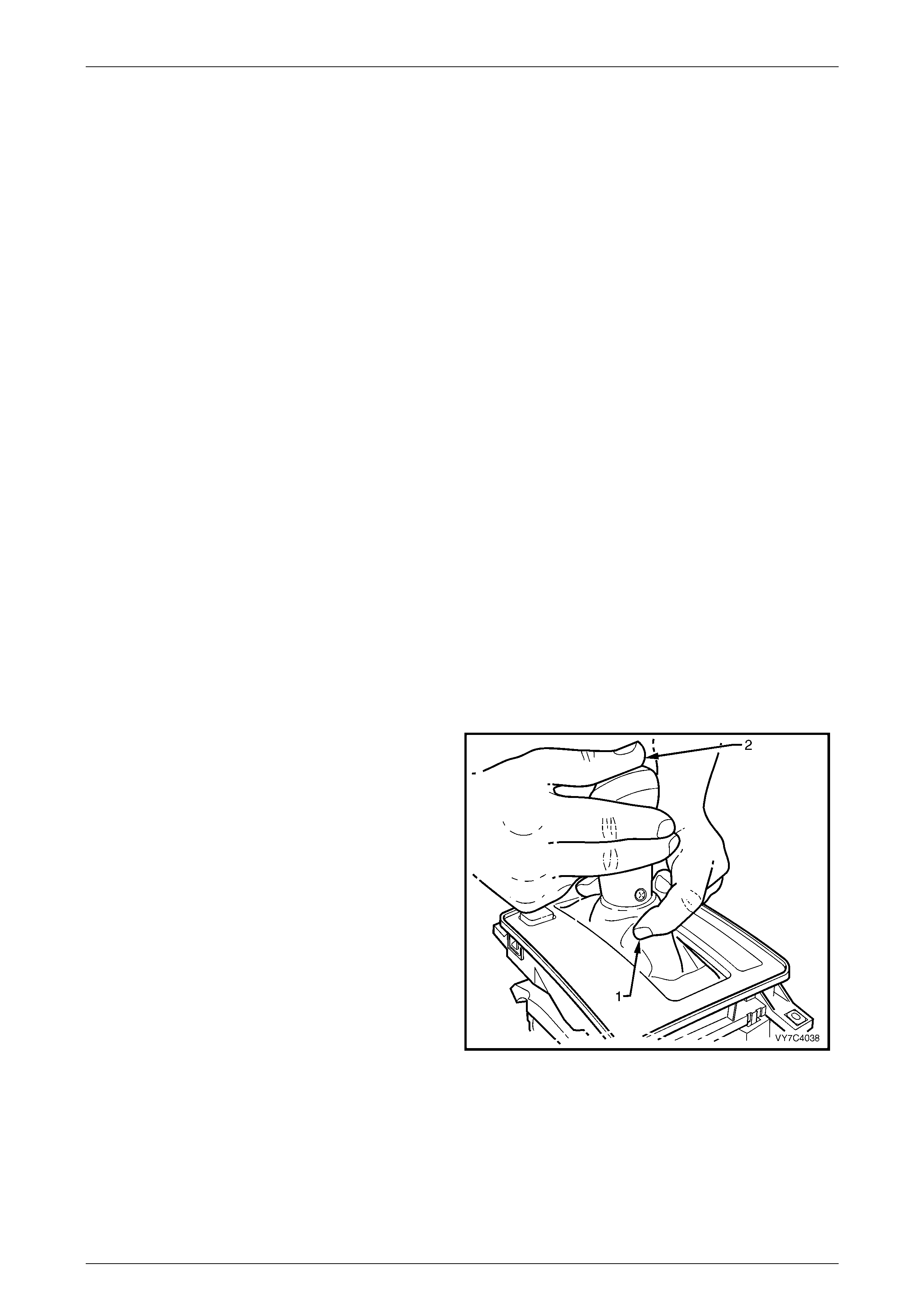
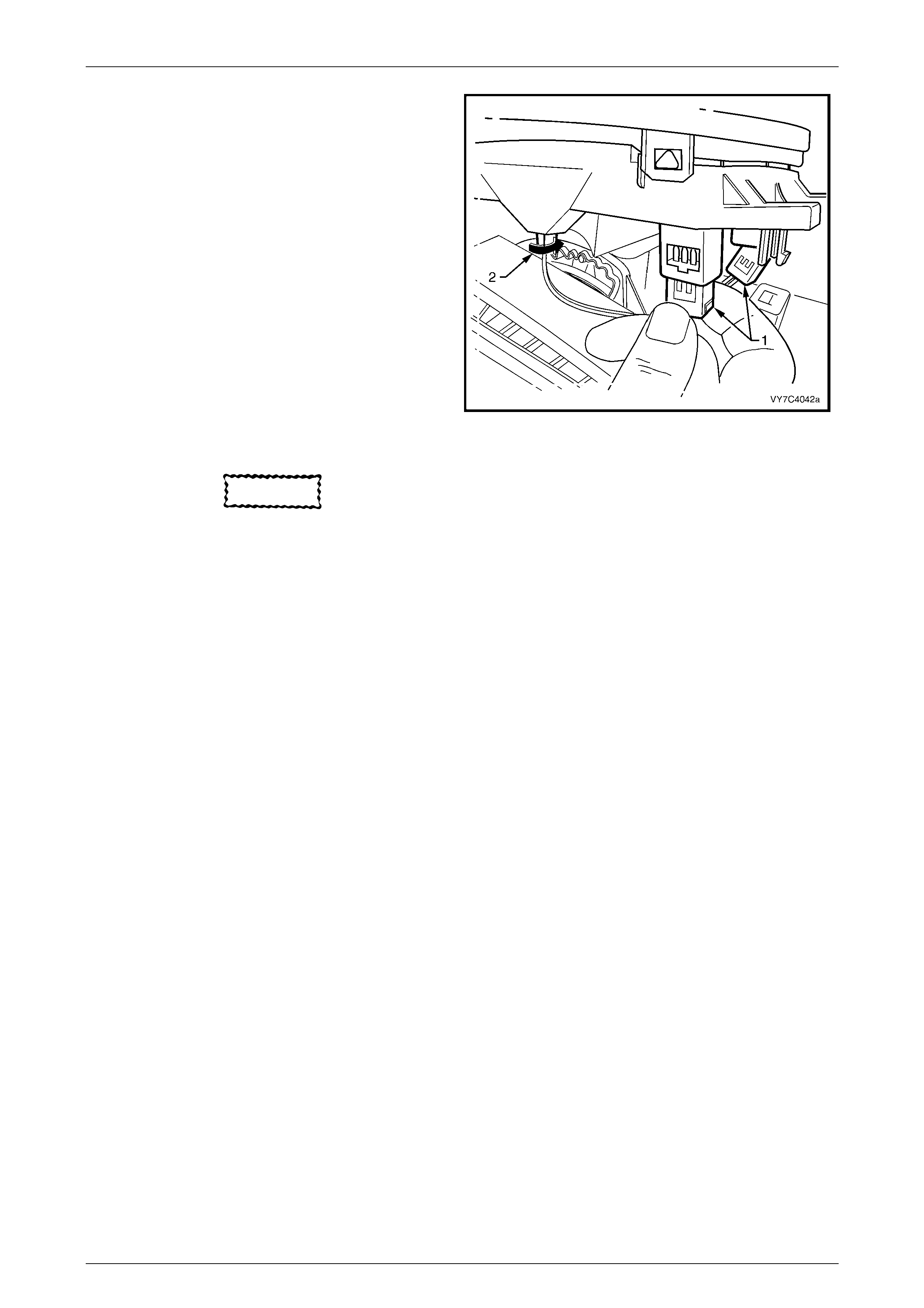
1 If the selector control lever assembly is of the BTSI
design, manually release the interlo ck mecha nism, as
follows:
a. First, press inwards at the front of the selector
lever (1), just below the gearshift knob, as
shown.
b. Then, while still pressing inward (1), depress the
selector knob with the other hand (2) and move
the lever from the Park position and into the ‘D’
position.
NOTE
This is the recommended reassembly position.
Figure 7C-1
Hydra-Matic 4L60-E A utomatic Transmission Page 7C–6
28–FEB–2003 Page 7C–6
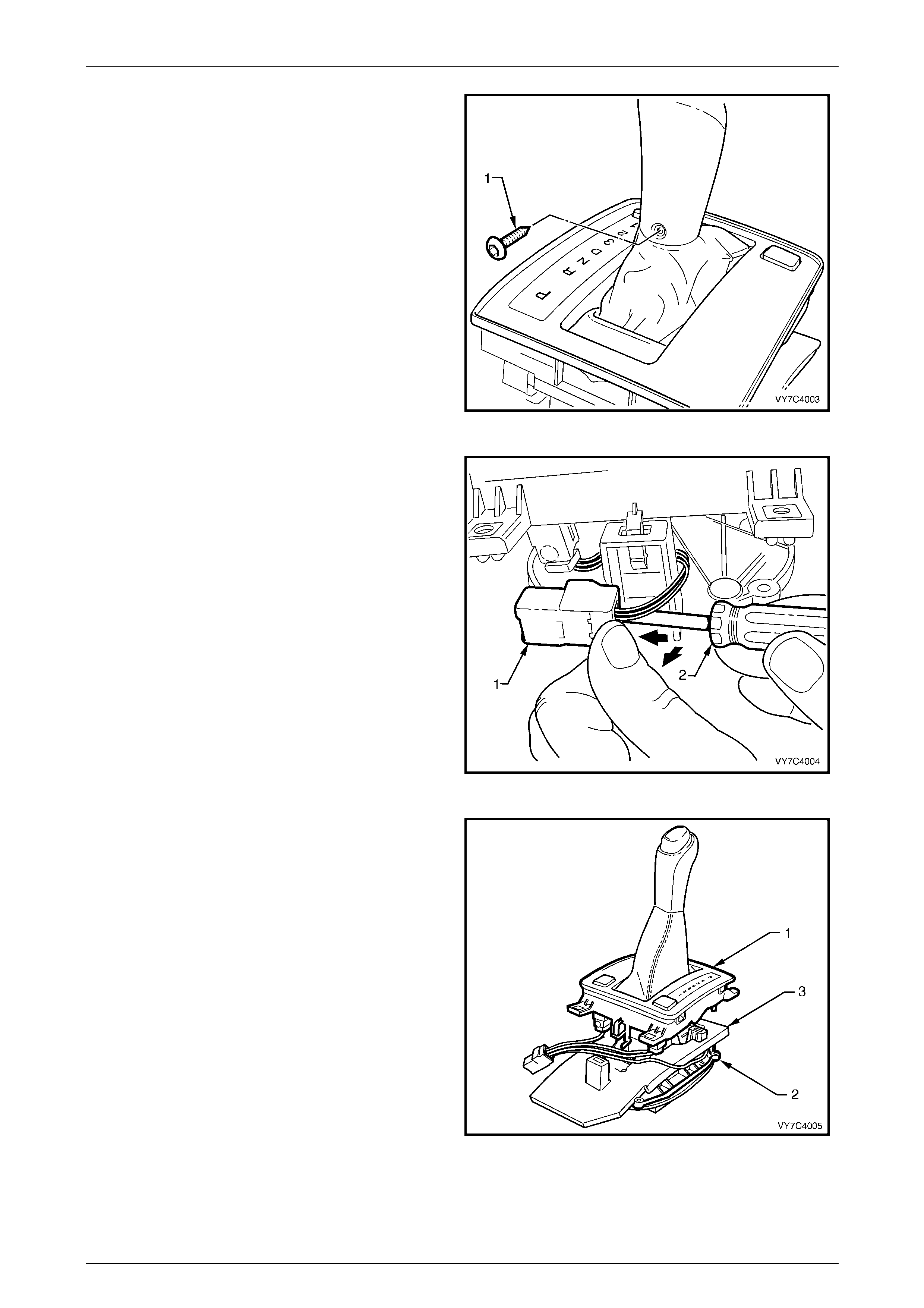
2 Using a commercially available Torx Plus (TX20) and
suitable equipment, remove the self-tapping
screw (1). Select the ‘D’ position.
Figure 7C-2
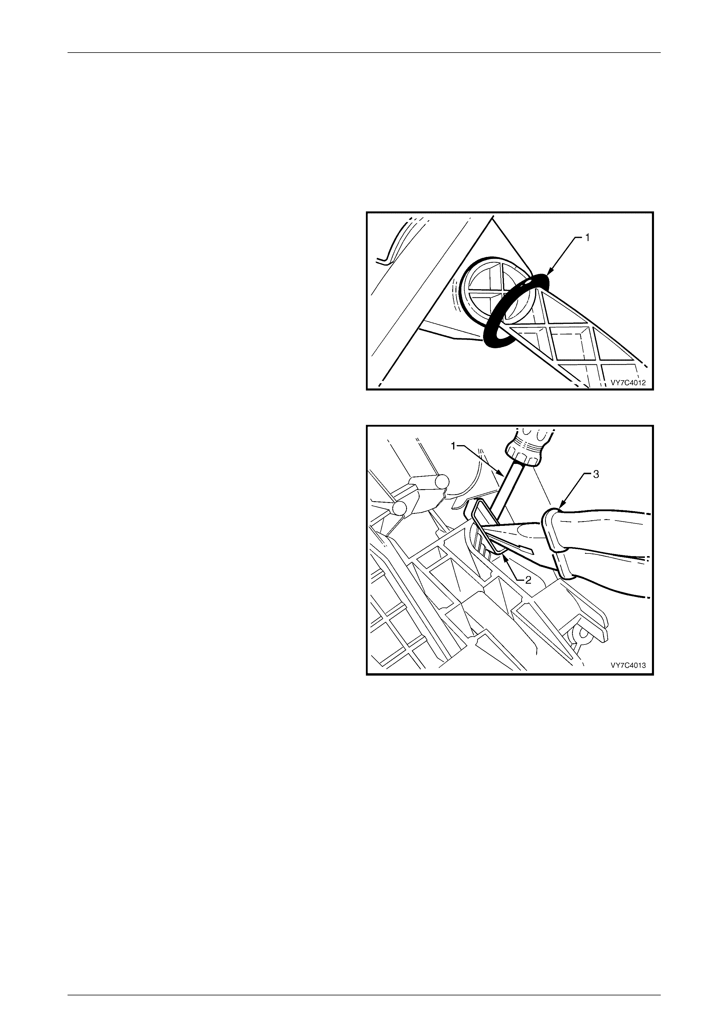
3 Using a small screwdriver (2), prise the locking tab on
the wiring harness connector (1) at the rear of the
shift selector assembly, while pushing away from the
lower housing, as shown.
NOTE
This operation is optional with the BTSI shifter,
as:
a. The patch harness can be disconnected at the
micro switch and the solenoid (in which case,
step 3 is required).
OR
b. Following separation of the lower housing and
the base (see step 4), the wiring harness
connectors could be removed from the ‘PW R’
and ‘T/C’ (if fitted) switches, leaving the harness
with the base (step 3 not being required). Figure 7C-3
4 With the wiring harness connector removed,
disconnect the lower housing from the base (1) by
pressing the tangs on each of the retaining legs (two
front, one rear).
5 Lift the lower housing (1) from the base (2), together
with the switch/es, patch wiring harness, boot and
shift lever knob. Set the asse mbly to one side.
NOTE
With the BTSI shifter, when the patch harness is
left behind (choice ‘b’ in step 3), the removed
components will be; the lower housing (1),
together with the switch/es, boot and shift lever
knob.
6 As required, lift the insulator (3) from the base (2) and
set to one side.
Figure 7C-4
Hydra-Matic 4L60-E A utomatic Transmission Page 7C–7
28–FEB–2003 Page 7C–7
NOTE
With the shift lever assembly now separated,
select from the following choices for the service
operation/s required.
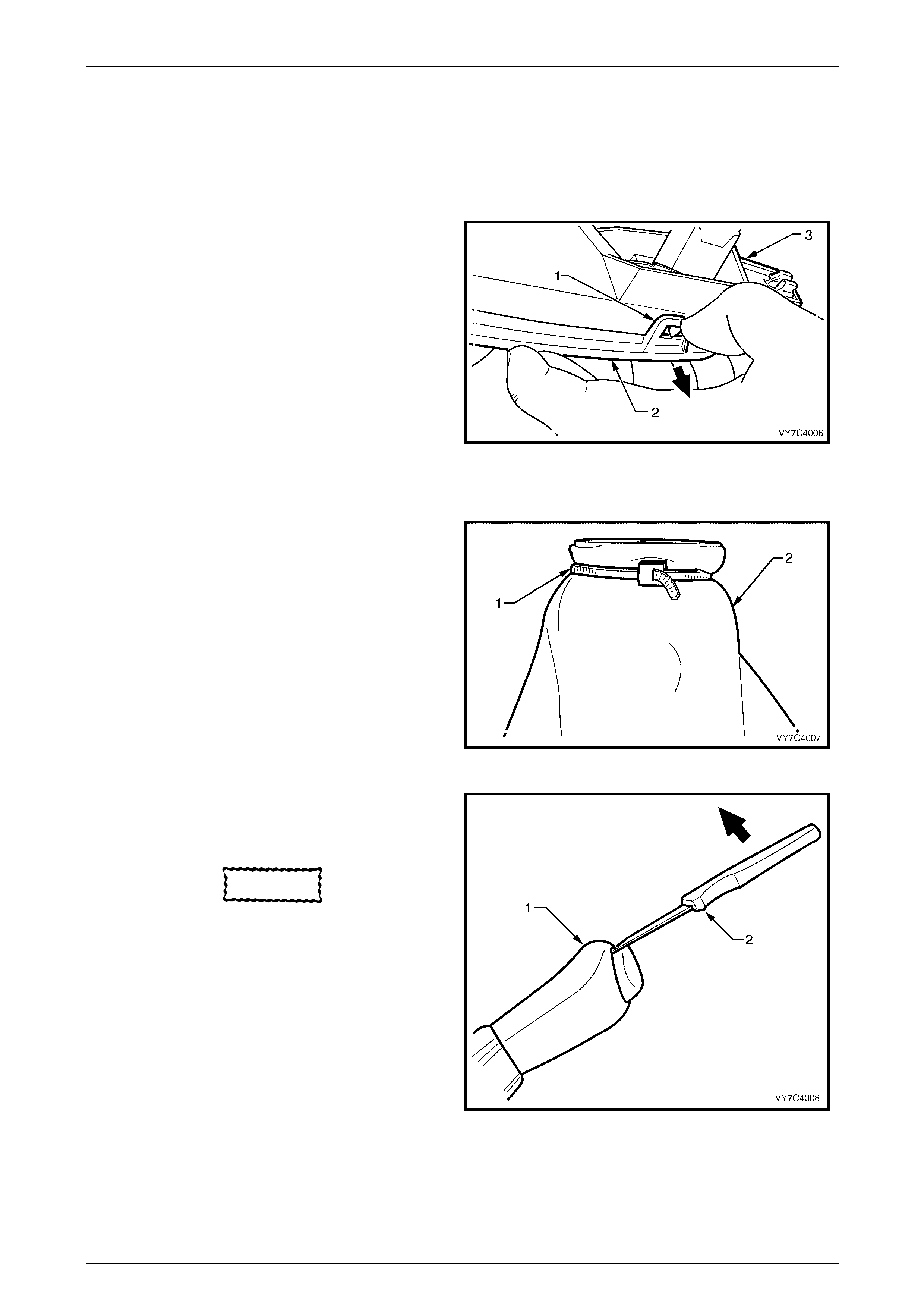
Boot, Shift Lever Knob Remove
1 While holding the lower housing in an inverted
position, gently prise each of the four securing lugs
(1) to free the cover (2) from the lower housing (3).
Lift the lower housing (3) from the gearshift selector
knob, boot and upper cover assembly (2) and set to
one side.
NOTE
If the lower housing assembly is not inverted
before separation, then the boot will probably
become dislodged from the locating tangs in the
upper cover.
2 If boot replacement is required, free the boot from the
upper cover locating tangs and set the cover to one
side, being careful not to dislodge nor damage the
PRNDL indicator lens in the process.
Figure 7C-5
3 Turn the boot (2) inside out, over the gearshift
selector knob, then cut the plastic tie (1) securing the
boot to the knob. Remove the boot from the gearshift
lever knob and discard.
NOTE
The plastic tie is a unique design and is
markedly different from the usual cable tie.
Ensure to use the correct part when
replacement of the cable tie is required.
Figure 7C-6
4 If the gearshift knob needs to be dismantled, use a
small knife (2) or similar to free the lugs securing the
control rod button from the gearshift knob (1).
CAUTION
The knob is spring loaded and may fly
free once dislodged.
5 Remove the two Phillips head self-tapping screws,
(located under the control rod button), then separate
the knob components.
Figure 7C-7
Hydra-Matic 4L60-E A utomatic Transmission Page 7C–8
28–FEB–2003 Page 7C–8
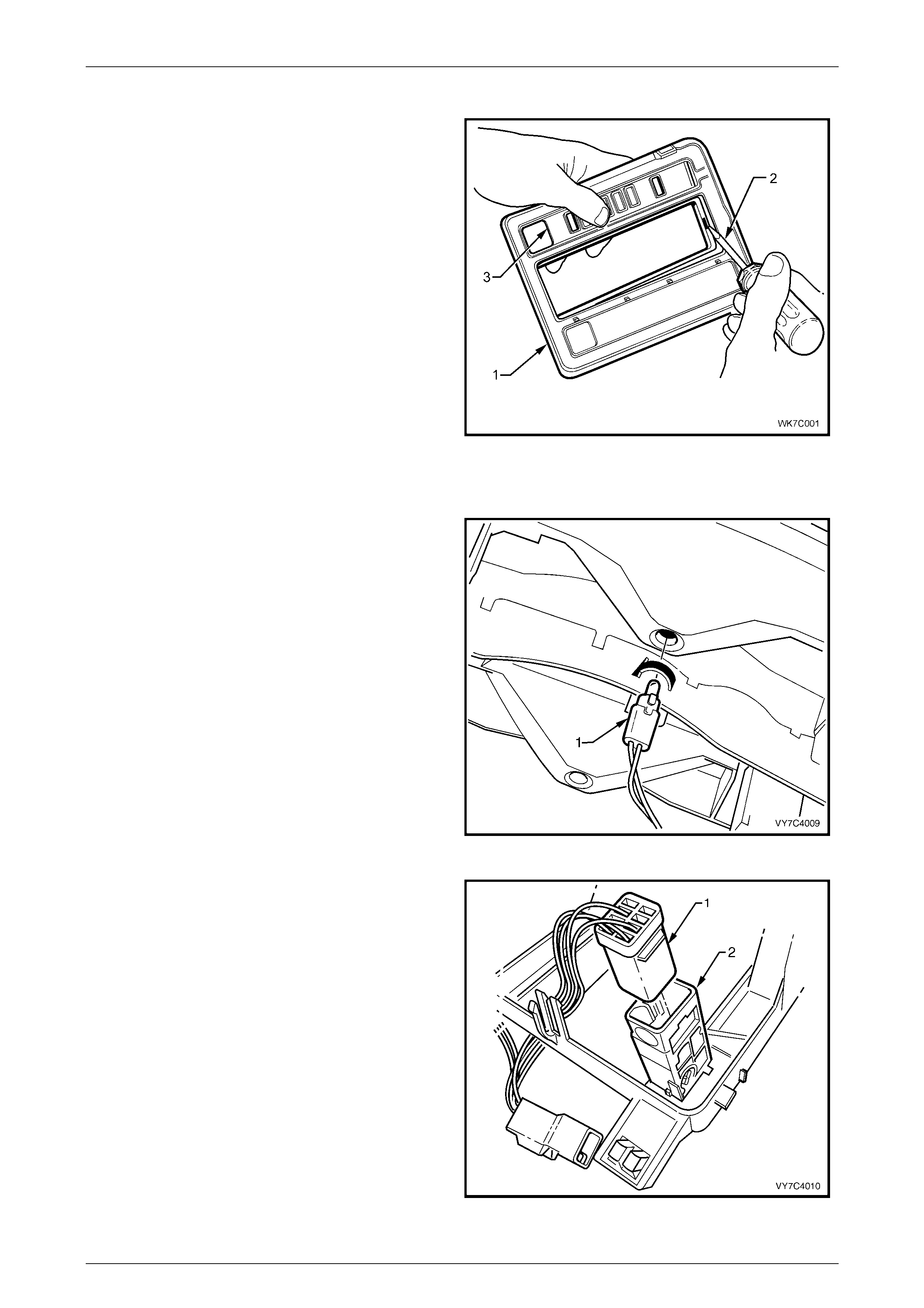
Chrome Escutcheon Remov e
1 Hold the lower housing cover (1) upside down and
using a fine flat tip screw driver (2), carefully prise the
eight retaining tangs on the chrome escutcheon (3)
free from the edge of the shift lever boot opening.
2 Remove the chrome escutcheon from the lower
housing.
Figure 7C-8
Patch Harness Remove
1 Remove the selector indicator lamp and holder from
the switch housing by turning the lamp holder 90° to
the left (counter-clockwise), and withdraw the holder.
Figure 7C-9
2 If not removed previously (step 3), release the switch
connector retaining lug/s, then remove the
connector/s.
NOTE
While each switch patch harness connector is
the same colour (white), the Traction Control
('T/C') switch (where fitted) connector wiring is
taped to the PRNDL indicator lamp wiring, as
this switch will always be on the same side as
this lamp. This situation remains the same for
both RHD and L HD vehicles.
Figure 7C-10
Hydra-Matic 4L60-E A utomatic Transmission Page 7C–9
28–FEB–2003 Page 7C–9
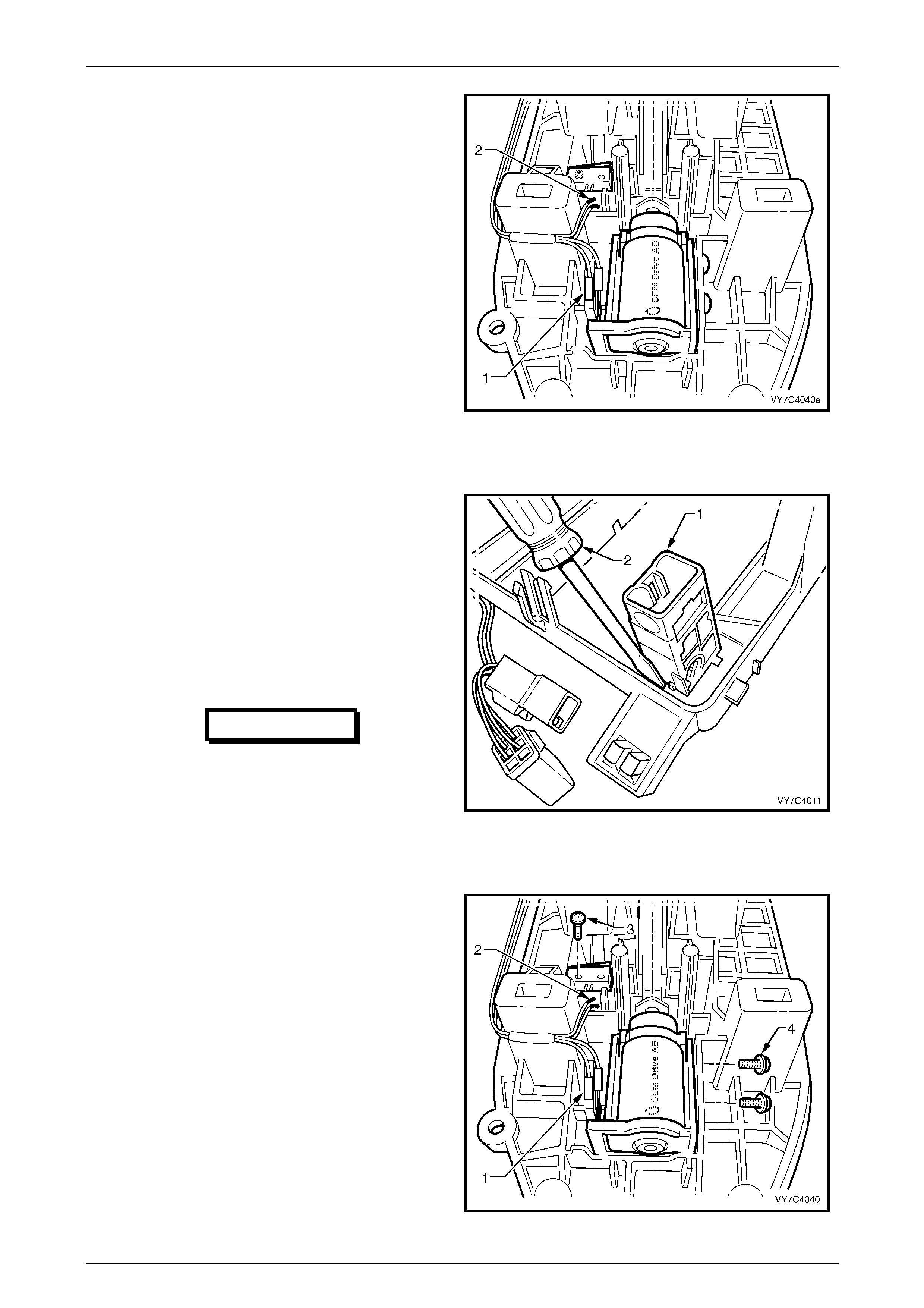
3 If the shift lever assembly is of the BTSI design,
remove the patch harness wiring connectors from the
solenoid (1) and the micro switch (2), taking note of
the patch harness routing, for correct reinstallation.
4 Remove the patch harness and set to one side.
Figure 7C-11
Switch Remove
NOTE
For this operation, the cover must be separated
from the lower housing. Refer to Step 4 in this
procedure.
1 To remove the PWR and/or T/C switch (if fitted), use
a small bladed screwdriver and lever one of the
switch retaining tangs from under the lower housing
to free the particular switch, cock to one side, release
the second tang and then remove the switch from
above.
IMPORTANT
Take note of the locating lug on the
switch body that ensures the correct
orientation of the switch when reinstalled.
Figure 7C-12
BTSI Solenoid and/or Micro Switch
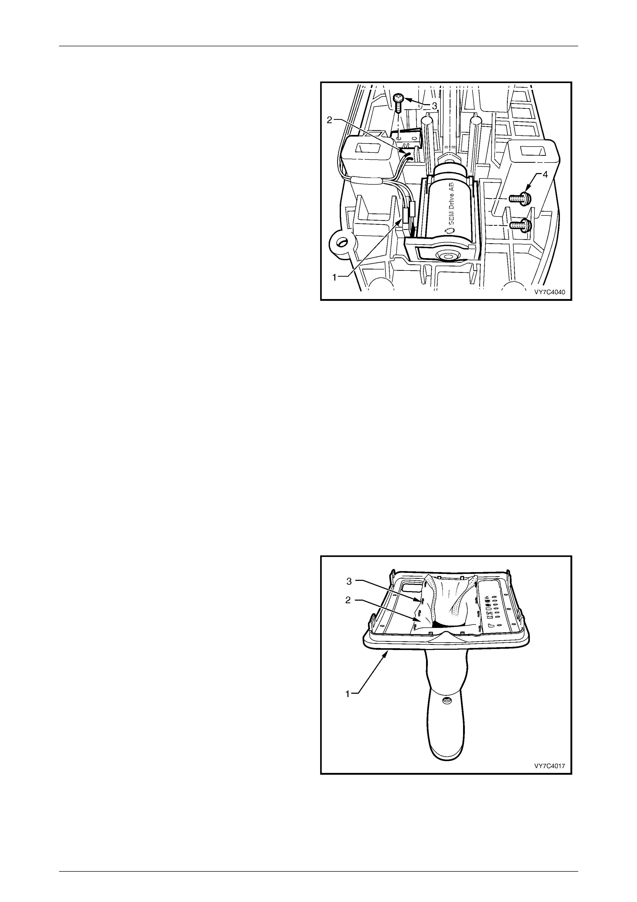
1 With the lower cover separated from the base, lift the
insulator back and over the shift lever.
2 With the patch harness connectors (1 and 2) removed
from the micro switch and the solenoid, remove the
two Phillips headed screws (4) securing the solenoid
or the single self tapping screw (3) from the micro
switch.
3 Remove the solenoid and/or micro switch from the
BTSI base.
Figure 7C-13
Hydra-Matic 4L60-E A utomatic Transmission Page 7C–10
28–FEB–2003 Page 7C–10
Base Disassemb l y
1 If not removed previously, remove the shift rod trunnion bolt from the lower end of the shift lever arm. Slide the
trunnion from the arm, then remove the insulating grommet.
NOTE
This is necessary to provide clearance for the
lever to be removed from the lower housing.
2 Remove the external seal (1) from the lever arm and
set to one side.
Figure 7C-14
3 To remove the lever locking piece, use a small
screwdriver (1) to lever the locking tang free while
pulling on the locking piece (2) with long nosed
pliers (3).
4 Push the lever assembly inward to release the inner
support pin and bush.
NOTE
The bush will probably remain in the lower
housing.
5 Lift the shift lever from the lower housing.
NOTE
While it will be necessary to manoeuvre the
lever somewhat, sufficient space is provided to
prevent any need to apply force to the lever
assembly.
Figure 7C-15
Lever Disassembly
NOTE
Regardless of the shift lever type, further
disassembly is not recommended, as it is highly
possible that, during reinstallation of the roll pin,
the shift lever will be cracked, unless
sophisticated jigs are used. For this reason, the
shift lever is only serviced as an assembly.

Hydra-Matic 4L60-E A utomatic Transmission Page 7C–11
28–FEB–2003 Page 7C–11
Reassemble
Base Reassembl y
1 Inspect the external lever, inner bushing (1) for
damage, replacing as required. Lubricate with multi-
purpose chassis grease such as NLGI No. 1 Lithium
grease.
2 Install the split inner support bush (2) to the selector
lever pin, aligning the split in the bush with the key on
the selector lever pin. Lubricate the external bush
surface with multi-purpose chassis grease such as
NLGI No. 1 Lithium grease.
3 Install the selector lever assembly (3), into the base.
Align the small bush with the aperture in the base
then push across to fully install the lever.
Figure 7C-16
4 Install the lever locking piece (1), using long nosed
pliers. Correct reinstallation will have occurred when
an audible click is heard, indicating that the tang on
the locking piece has been installed correctly.
NOTE
While a standard shift lever is shown, the
reinstallation is the same for the BTSI design.
Figure 7C-17
5 Apply a smear of multi-purpose chassis grease such
as NLGI No. 1 Lithium grease to the outer, lipped seal
(1), then reinstall over the external lever.
Figure 7C-18
Hydra-Matic 4L60-E A utomatic Transmission Page 7C–12
28–FEB–2003 Page 7C–12
BTSI Solenoid and/or Micro Switch
1 Install the solenoid and/or micro switch to the base,
securing with two screws (4) for the solenoid and/or
single self tapping screw (3) for the micro switch. Do
not over-tighten the screws.
2 Install the patch wiring harness connectors to the
micro switch (2) and/or solenoid (1).
3 Place the insulating foam into position.
NOTE
No adjustment is required for the BTSI solenoid.
Figure 7C-19
Lower Housing
1 If removed, install the switch/es to the lower housing, ensuring that the locating lug on the switch body engages
with the slot in the lower housing. If the vehicle is equipped with traction control, the correct location for this switch,
is in the right hand aperture for RHD vehicles (the opposite side for LHD vehicles). This will always be behind the
PRNDL indicator lens.
2 Install the patch wiring harness, ensuring that the switch connector/s connection is correct. Also reinstall the
PRNDL lamp and holder, by inserting and turning the holder a quarter turn to the left (counter-clockwise).
3 If of the BTSI design, it is recommended that the patch harness be reinstalled to the solenoid and micro switch first,
then to the PWR and/or T/C switch (if fitted), prior to reassembling the lower housing assembly to the base (refer to
Figure 7C-23). In this instance, the wiring harness connector should also be installed to the bracket on the base, at
this time.
4 If a new selector lever boot is to be installed, use the tie strap included with the new boot to firmly secure the boot
to the gearshift selector knob. Trim excess length and discard.
5 If necessary, install the chrome escutcheon on to the lower housing cover by gently pressing into place until the
eight retaining tangs snap firmly into place.
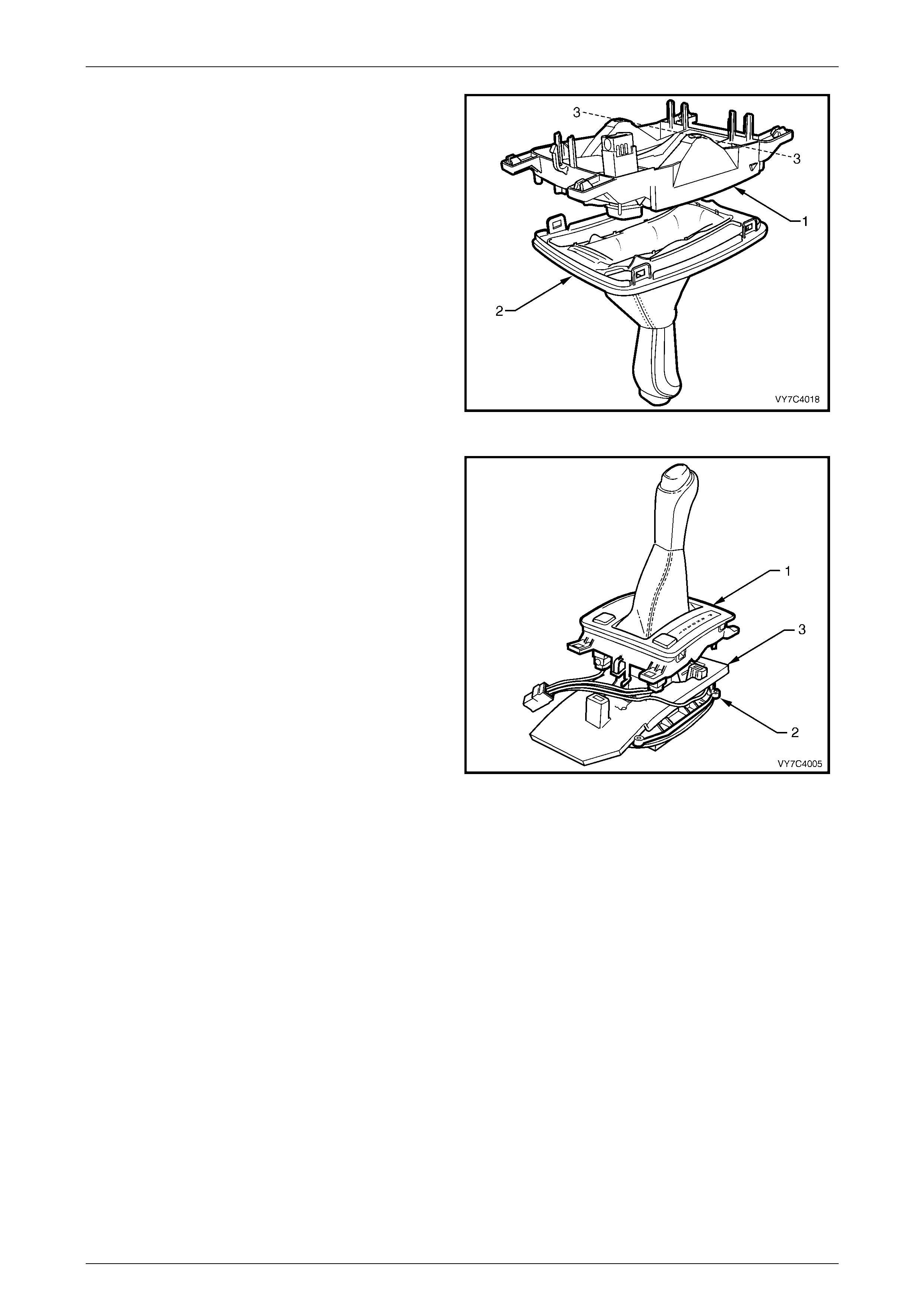
6 With the upper cover (1) inverted, locate the boot (2)
over each of the cover locating tangs (3), working
gradually around until every tang is covered.
NOTE
The weight of the selector knob will be sufficient
to keep the boot engaged with the tangs.
Figure 7C-20
Hydra-Matic 4L60-E A utomatic Transmission Page 7C–13
28–FEB–2003 Page 7C–13
7 To reduce the possibility of the boot from becoming
dislodged from the upper cover retaining tangs,
reinstall the lower housing (1) to the cover (2),
working in an inverted position, as shown.
NOTE
Before reassembling the lower cover to the
base, check that the coloured indicator is in line
with the two PRNDL display lamp h oles (3). This
will be the approximate position for correct
reassembly.
8 Engage each of the tabs on the upper cover with the
retaining lugs on the lower housing. When all four
tabs have been engaged, the boot will be clamped
and can no longer become disengaged.
Figure 7C-21
9 Ensure that the PRNDL indicator slide in the lower
housing, is at the 'D' position (the red colour will show
opposite the 'D' in the PRNDL lens).
10 After checking that the insulator (3) is undamaged,
reinstall to the base (2).
11 After checking that the selector lever is also in the
Drive position, reinstall the lower housing (1) over the
shift lever and engage each of the three legs with the
base apertures. Check that the PRNDL indicator slide
pin is engaged with the slot in the selector lever.
Figure 7C-22
Hydra-Matic 4L60-E A utomatic Transmission Page 7C–14
28–FEB–2003 Page 7C–14
NOTE
If the shifter is of the BTSI design, before
reassembling to the base, reinstall the patch
harness connector/s (1) to the PWR and/or T/C
switch (if fitted).
12 Install the selector indicator lamp and holder (2) by
inserting, then turn to the right (clockwise), to secure.
13 Engage the selector lever knob with the selector
lever, aligning the control rod with the hole in the
selector knob.
NOTE
Moving the selector lever can easily check
correct engagement of the PRNDL indicator.
Should the coloured portion not move with the
lever, then engagement is incorrect. Separate
the lower housing and base and repeat Steps
13 to 15.
CAUTION
If the shifter is of the BTSI design, do not
engage the Park position during this
testing process. If this does occur, the
interlock will need to be manually
released again (refer to Step 1 of the
Disassemble process).
Figure 7C-23
14 Install the selector knob retaining screw, using a TX20 Torx bit and suitable equipment, being careful not to over-
tighten.
15 Install the selector lever knob and spring, pushing down until the two locking tangs engage.
NOTE
If the selector lever knob and spring have not
been removed, then re-engagement with the
selector lever can still be achieved but some
manoeuvring may be necessary.
16 If removed, install the wiring harness connector onto the bracket at the end of the base and push until the locking
tang engages.
Reinstall
The reinstall procedure for the selector control lever assembly carries over from MY 2003 VY Series vehicles. For all
information relating to the reinstallation procedure for the selector control lever assembly, refer to Section 7C4, 3.3
Selector Control Lever Assembly in the MY 2003 VY Series and V2 Series Service Information.

Hydra-Matic 4L60-E A utomatic Transmission Page 7C–15
28–FEB–2003 Page 7C–15
5 Unit Repair
MY 2004 WK Series Hydra-Matic 4L60-E four speed automatic transmission unit repair information carries over from MY
2003 VY Series vehicles.
For all Hydra-Matic 4L60-E four speed automatic transmission unit repair information, refer to Section 7C3, Hydra-Matic
4L60-E Automatic Transmission: Hydraulic/Mechanical Diagnosis in the MY 2003 VY Series and V2 Series Service
Information.