
LPG System Page 8A2–1
Page 8A2–1
Section 8A2
LPG System
ATTENTION
Before performing any Service Operation or other procedure described in this Section, refer to Section 00
WARNINGS, CAUTIONS AND NOTES for correct workshop practices with regard to safety and/or property
damage.
1 General Information............................................................................................................................... 3
2 Service Operations................................................................................................................................5
2.1 Safety Precautions.................................................................................................................................................5
2.2 Service Lines..........................................................................................................................................................6
Front Service Line..................................................................................................................................................6
Remove..............................................................................................................................................................6
Reinstall..............................................................................................................................................................8
Intermediate Service Line......................................................................................................................................9
Remove..............................................................................................................................................................9
Reinstall............................................................................................................................................................11
2.3 Leak Testing .........................................................................................................................................................12
Gas Detectors.......................................................................................................................................................12
Combustible......................................................................................................................................................12
Foam ................................................................................................................................................................13
Leak Test Procedure............................................................................................................................................14
Leak Test Locations..........................................................................................................................................15
2.4 Fuel Mode Switch.................................................................................................................................................18
Remove .................................................................................................................................................................18
Reinstall ................................................................................................................................................................18
3 Diagnosis.............................................................................................................................................. 19
3.1 General Information.............................................................................................................................................19
3.2 Prerequisites to Diagnosis and Troubleshooting..............................................................................................20
Preliminary System Requirements.....................................................................................................................20
Safety Requirements............................................................................................................................................20
Checking Equipment ............................................................................................................................................20
3.3 LPG Vehicle Preliminary Diagnosis....................................................................................................................21
Test Description...................................................................................................................................................21
Test Procedure.................................................................................................................................................21
3.4 Vehicle Does Not Operate on LPG......................................................................................................................23
Test Description...................................................................................................................................................23
Test Procedure.................................................................................................................................................23
3.5 Fuel Mode Switch Does Not Operate..................................................................................................................25
Test Description...................................................................................................................................................25
Test Procedure.................................................................................................................................................25
3.6 Engine Does Not Crank .......................................................................................................................................27
Test Description...................................................................................................................................................27
Test Procedure.................................................................................................................................................27
3.7 Engine Cranks But Will Not Start on LPG..........................................................................................................28
Test 1 Description................................................................................................................................................28
Test Procedure.................................................................................................................................................28
Test 2 Description................................................................................................................................................30
Test Procedure.................................................................................................................................................30
Test 3 Description................................................................................................................................................32
Test Procedure.................................................................................................................................................32
Techline

LPG System Page 8A2–2
Page 8A2–2
3.8 Engine Backfires on LPG.....................................................................................................................................34
Test Description...................................................................................................................................................34
Test Procedure.................................................................................................................................................34
3.9 Poor Performance, Flat Spotting, Sluggish or Poor Fuel Consumption.........................................................37
Test Description...................................................................................................................................................37
Test Procedure.................................................................................................................................................37
3.10 Fuel Control Valve Does Not Operate.................................................................................................................39
Test Description...................................................................................................................................................39
Test Procedure.................................................................................................................................................39
4 Wiring and Connectors ....................................................................................................................... 41
Wiring Schematics...............................................................................................................................................42
Connectors ...........................................................................................................................................................43
5 Specifications....................................................................................................................................... 44
6 Tech 2 Scan Tool: Engine Data .......................................................................................................... 45
7 Torque Wrench Specifications........................................................................................................... 46

LPG System Page 8A2–3
Page 8A2–3
1 General Information
With the following exceptions, MY 2004 WK Series LPG information carries over from the MY 2004 VY Series Sedan.
For information not contained within this Section, refer to Section 8A2 LPG System in the MY 2004 VY and V2 Series
Service Information.
• Front and intermediate service lines
• Leak testing
• Fuel mode switch
• Diagnostics
• Wiring and Connectors
MY 2004 WK Series vehicles can be fitted with optional LPG system, production option KL7, where the vehicle has a
V6 non supercharged engine and automatic transmission.
The driver is able to switch the vehicle to LPG or petrol operation via a fuel mode switch, located in the front floor
console, even while the vehicle is being driven. An icon is displayed on the instrument cluster when LPG is selected and
the standard fuel gauge changes from displaying the contents of the petrol tank to the LPG tank contents.
The front service line from the LPG lock off joins the intermediate line below the driver's door sill panel. The intermediate
service line runs along the underside of the body and is attached using retaining clips, which are fastened to the body
using pop rivets. Both service lines are unique to WK Series vehicles. The rear service line carries over from the
MY 2003 VY Series Sedan noting that where fitted, the premium audio amplifier will require removal, refer to Section 12D
Audio Systems.
For further information relating to Tech 2 operation and diagnostics, refer to Section 0C.
As part of the KL7 production LPG option, MY 2004 WK Series vehicles are fitted with an up-rated spring package to
compensate for the extra weight of the LPG tank. For further information on rear suspension specifications, refer to
Section 4A Rear Suspension.
To identify vehicles that are fitted with the KL7 LPG option, a Holden By Design (HBD) identification plate is attached to
the upper front panel, refer to Section 8A2, 1.2 Identification Plates and Warning Labels in the MY 2003 VY and V2
Series Service Information.
Any servicing or testing of the LPG high pressure system must be performed by trained and/or licensed LPG installers or
fitters, in a Specialist Gas Workshop and in accordance with Australian Standards AS 2746-1999 and AS 1425-1999.
The relevant Australian Standards for LPG vehicles and workshops are:
• AS/NZS 1425 – 1999 – LP Gas Fuelled Systems for Vehicle Engines.
• AS 2746 – 1999 – Working Areas for Gas Fuelled Vehicles.
• AS 2030 - 1 – 1999 – The Approval, Filling, Inspecting, Testing and Maintenance of Cylinders for the Storage and
Transportation of Compressed Gasses, (Known as the SAA Gas Cylinder Code).
Standards Australia will issue updated amendments to Australian Standards as required. When referring to any
Australian Standard it is important to ensure that the latest edition of the relevant Australian Standard is used, including
any amendments as issued.
LPG System Page 8A2–4
Page 8A2–4
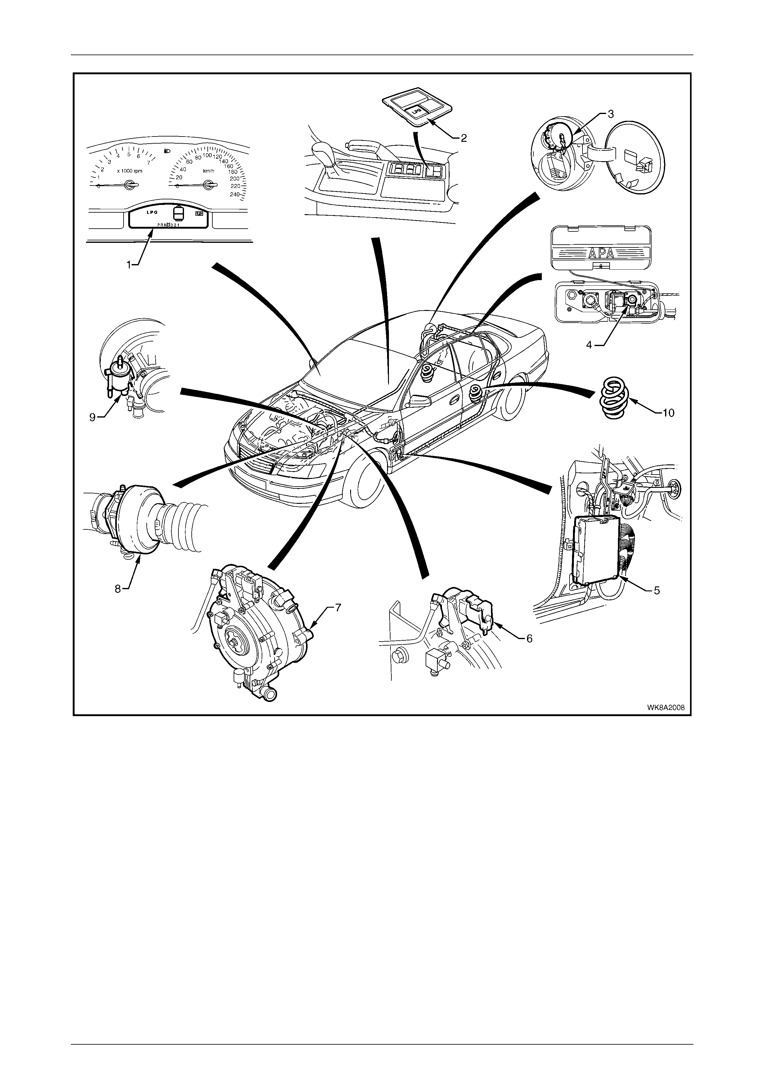
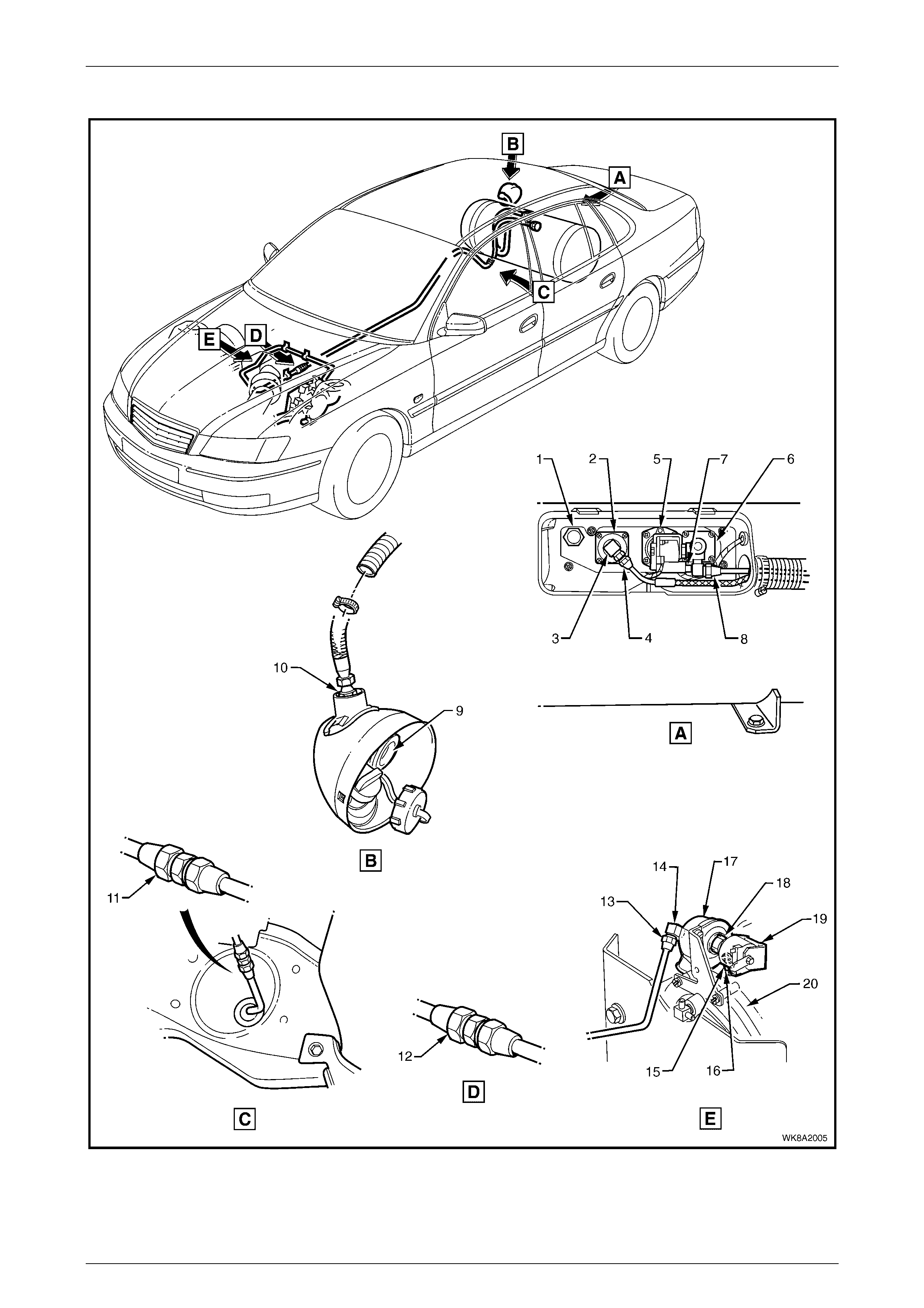
Figure 8A2 – 1
Legend
1 Instrum ent Cluster Display LP G Icons
2 Fuel Mode Switch
3 LPG Filler Valve
4 Manual Service V alve Assembl y
5 Powertrain Control Module (P CM)
6 LPG Lock-off
7 Converter
8 Mixer
9 Fuel Control Valve
10 Rear Coil Spring

LPG System Page 8A2–5
Page 8A2–5
2 Service Operations
2.1 Safety Precautions
Any servicing or testing of the LPG system that involves the high pressure side of the system must be performed by
trained and/or licensed LPG installers or fitters, in a Specialist Gas W orkshop and in accordance with Australian
Standards AS 2746-1999 and AS 1425-1999.
Normal vehicle maintenance, service and any servicing of the LPG system not affecting the high-pressure side (filler line,
LPG tank, service lines, LPG lock-off and converter) may be performed by dealership technicians who are not accredited
installers or fitters.
LPG must never come in contact with any part of the body as it can cause severe frostbite. Due to its very low boiling
point, LPG readily absorbs heat from its surroundings or any surface it comes in contact with when released into the
atmosphere.
When working on the LPG system, suitable protective clothing including gloves and safety goggles must be worn to
prevent personal injury.
LPG in the vapour form is highly flammable. In the interests of safety, the LPG system should be leak tested and isolated
by turning off the manual service valve and draining the service lines of LPG prior to commencing any work on the
vehicle, refer to 2.3 Lea k Testi ng in this Section.
During servicing, the manual service valve must remain off at all times, except when gas is specifically required for
servicing or testing of the LPG system.
Whenever any service operation is performed on the high-pressure area of the system (filler line, LPG tank, service lines,
LPG lock-off and converter), a leak test must be performed on the complete LPG system, refer to 2.3 Leak Testi ng in this
Section.
Prior to the removal of any component from the LPG tank, the LPG tank must be emptied of LPG, refer to Sect ion 8A2,
3.2 LPG Tank Unloading in the MY 2003 VY and V2 Series Service Information. The LPG tank must then be safety
tested in accordance with Australian Standard AS 2030-1 and according to the laws of the state in which the vehicle is
registered. A leak test must be performed on the complete LPG system before the LPG tank is returned to service in the
vehicle.
Do not smoke or allow naked flames, or any ignition source near the vehicle while working on the LPG system.
LPG System Page 8A2–6
Page 8A2–6
2.2 Service Lines
LT Section No. – AA-650Q
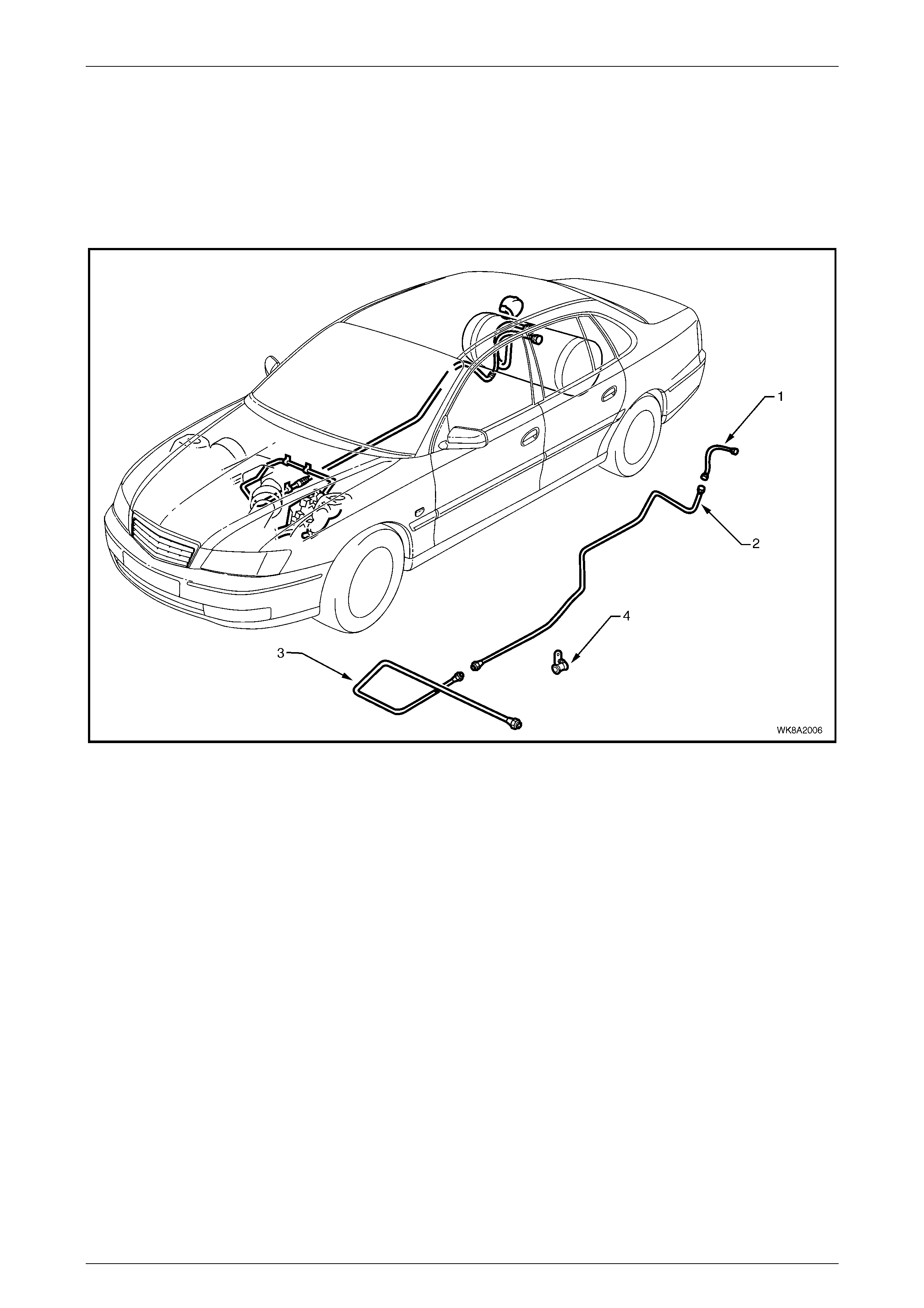
The service line carries the LPG from the manual service valve assembly to the LPG lock-off. The service line consists of
three major components: the rear service line (1), intermediate service line (2) and front service line (3),
refer to Figure 8A2 – 2.
Figure 8A2 – 2
Legend
1 Rear Service Li ne *
2 Intermedi ate Service Line 3 Front Service Line
4 Retaining Cli p, S even Places
* For rear service line service operations, refer to Section 8A2, 3.15 Rear Service Line in the MY 2003 VY and V2 Series
Service Information.
Front Service Line
Remove
NOTE
All servicing and maintenance which involves the
‘high pressure’ side of the LPG system, must only
be carried out by licensed personnel in licensed
workshops in accordance to AS 2746-1999
(Working Areas for Gas Fuelled Vehicles) plus
amendments.
1 Park the vehicle and drain the service lines of LPG, refer to Section 8A2, 3.1 Service Line Draining in the MY 2003
VY and V2 Series Service Information.
2 Remove the right-hand front exhaust assembly, refer to Section 8B, 2.6 Front Exhaust Assembly.
LPG System Page 8A2–7
Page 8A2–7
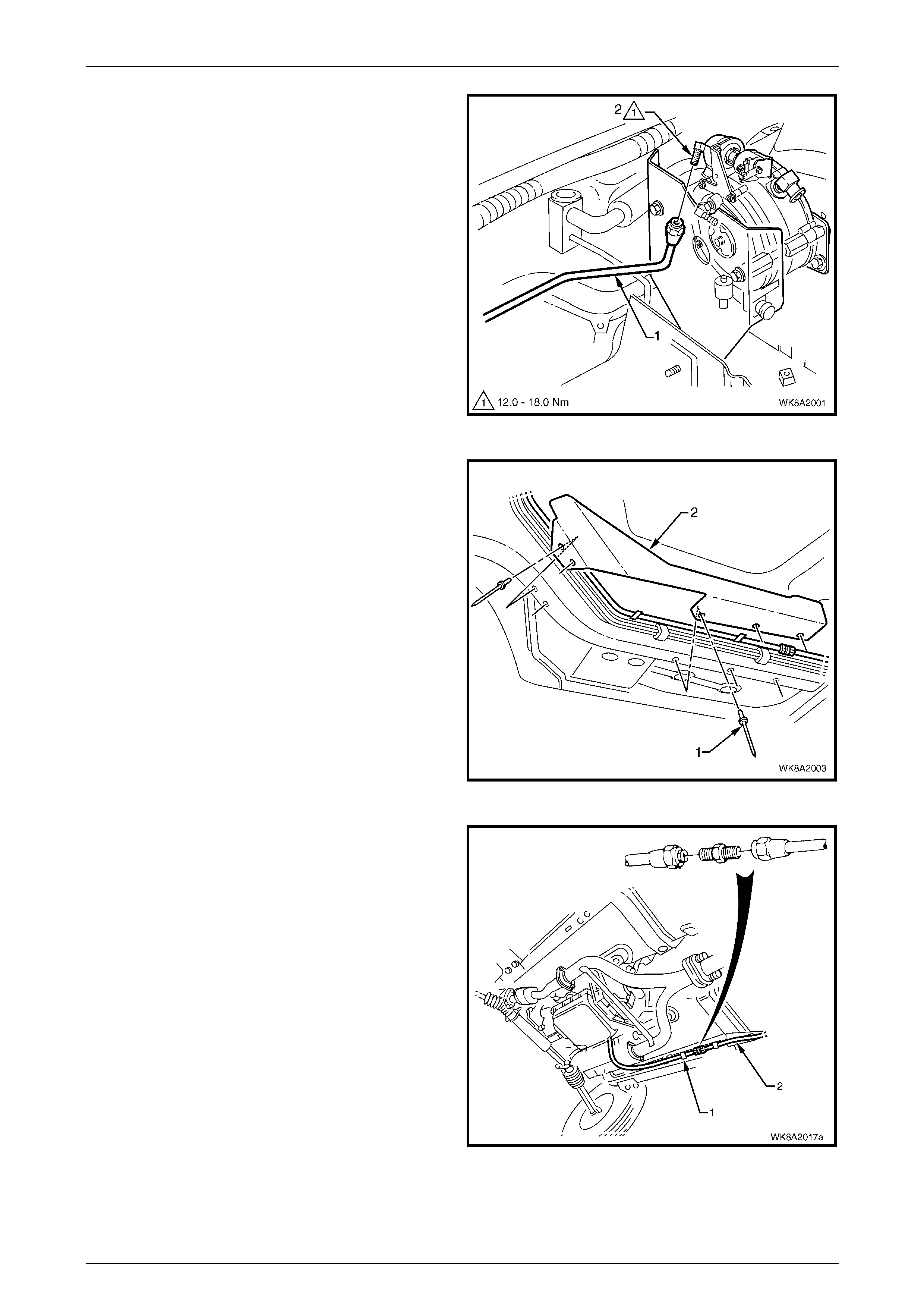
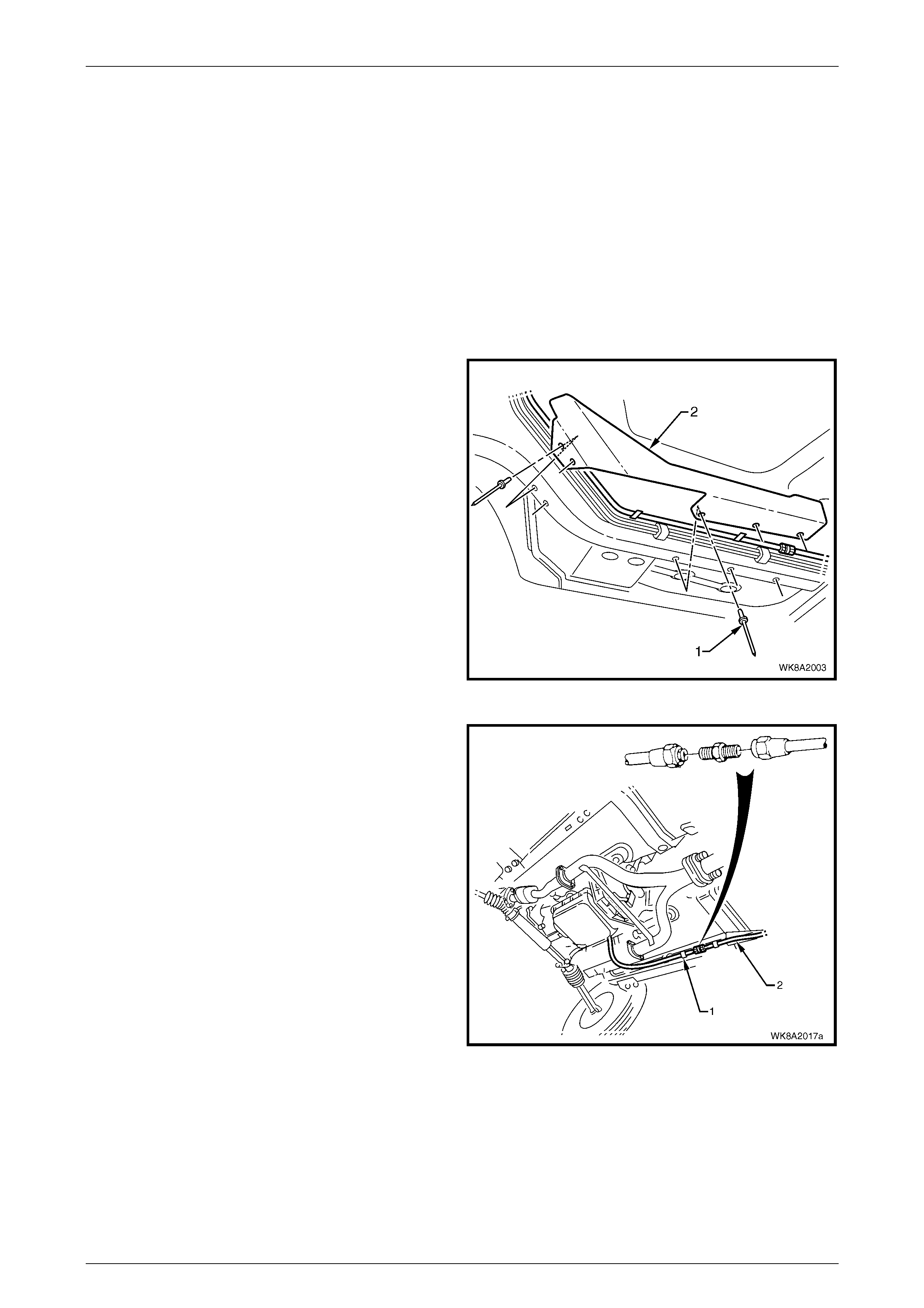
3 Disconnect the front service line (1) connector from
the LPG lock-off connection (2).
Figure 8A2 – 3
4 Remove the pop rivets (1), five places, attaching the
fuel harness heat shield (2) to the underside of the
vehicle.
5 Remove the LPG service line retaining clip, located
behind the heat shield by drilling the head off the rivet.
Figure 8A2 – 4
6 Disconnect the front service line (1) to intermediate
service line (2) connector.
Figure 8A2 – 5
LPG System Page 8A2–8
Page 8A2–8
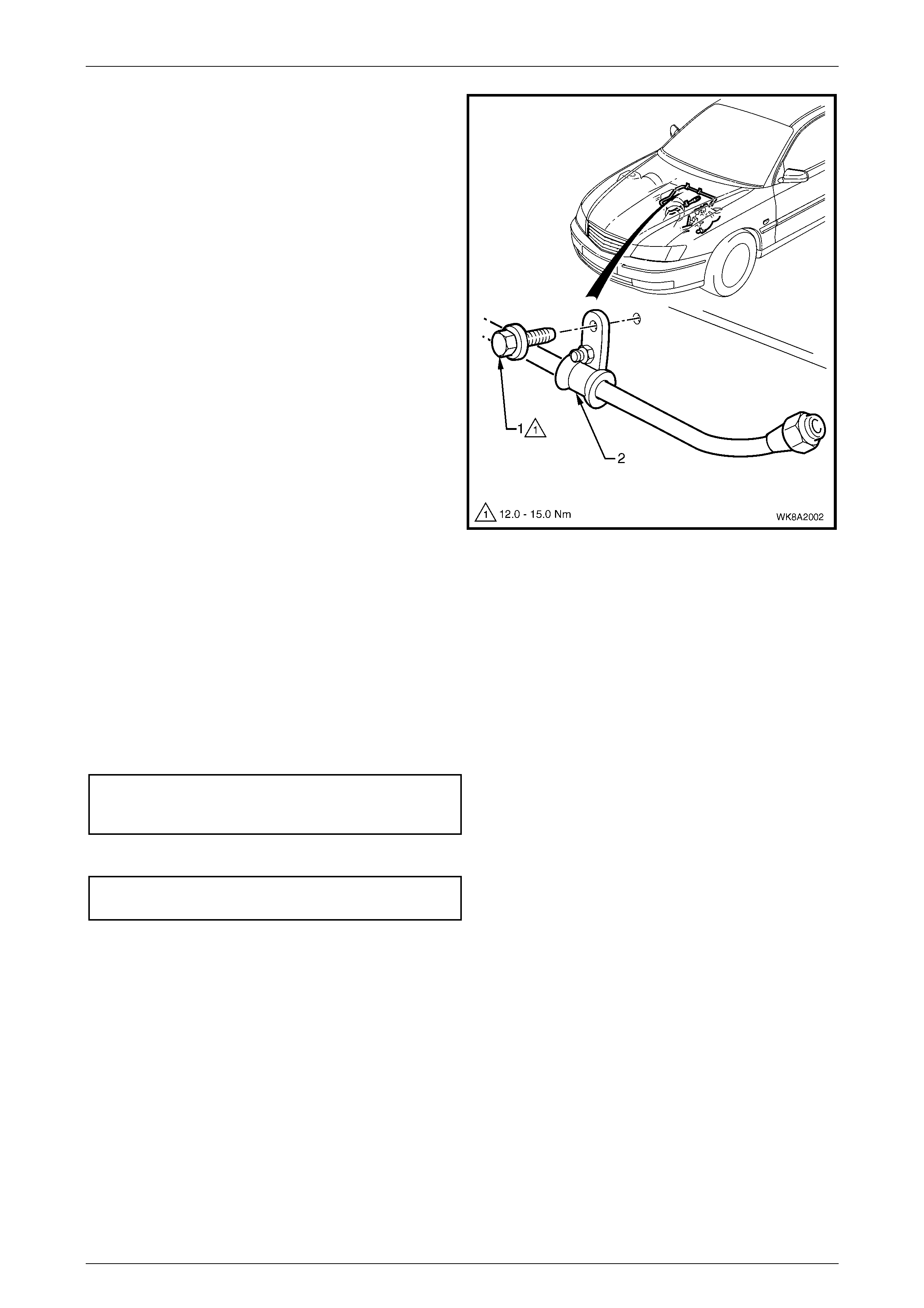
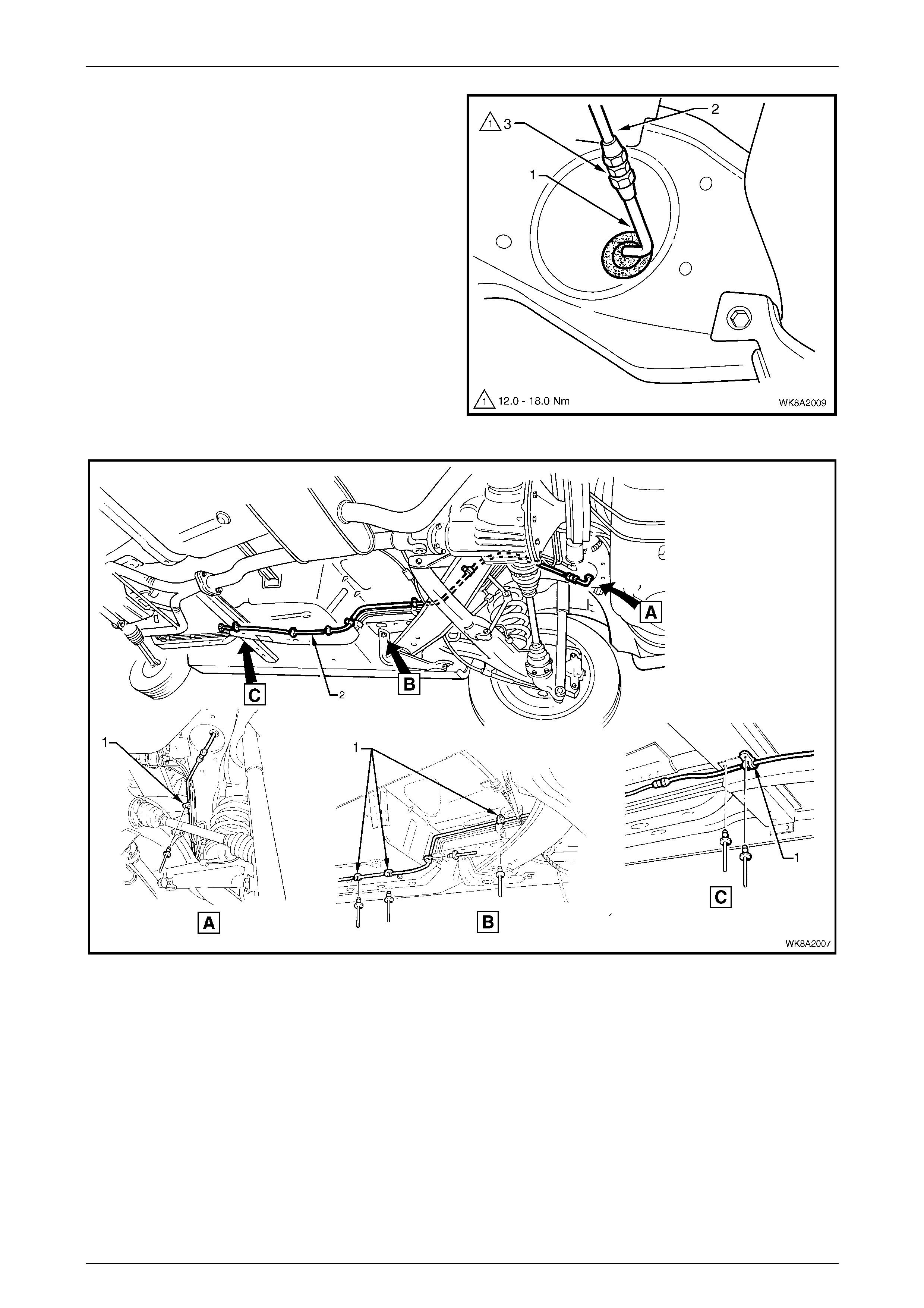
7 Remove the screw (1) attaching the LPG service line
retainer clip (2), two places to the dash panel.
8 Remove the LPG service line from the vehicle.
Figure 8A2 – 6
Reinstall
Reinstallation of the front service line is the reverse of the removal process noting the following:
1 Clean the mating threads of the front service line, LPG lock-off connection and intermediate to front service line
connector.
2 Apply, Loctite 577 sealant or equivalent to the LPG lock-off connection and to the intermediate service line front
connector threads, ensuring that flared surfaces are free of sealant and contaminants.
3 Assemble the front service line connectors to the LPG lock-off connection and intermediate service line connector
and tighten to the correct torque specification.
Front service line to lock-off and
intermed iate serv i ce line con n ector
torque specification ................................ 12.0 – 18.0 Nm
4 Reinstall the service line retainer clips to the dash panel and tighten the screws to the correct torque specification.
Front service line clip attaching screw
torque specification ................................ 12.0 – 15.0 Nm
NOTE
Ensure the front service line does not chafe or
come in contact with the body or other
components.
5 Reinstall the LPG service line retaining clip and heat shield with new pop rivets.
6 Reinstall the right-hand exhaust assembly, refer to Section 8B, 2.6 Front Exhaust Assembly.
7 Leak test the LPG system, refer to 2.3 Leak Testing.
LPG System Page 8A2–9
Page 8A2–9
Intermediate Service Line
Remove
NOTE
All servicing and maintenance which involves the
‘high pressure’ side of the LPG system, must only
be carried out by licensed personnel in licensed
workshops in accordance to AS 2746-1999
(Working Areas for Gas Fuelled Vehicles) plus
amendments.
1 Park the vehicle and drain the service lines of LPG, refer to Section 8A2, 3.1 Service Line Draining in the MY 2003
VY and V2 Series Service Information.
2 Remove the five pop rivets (1) attaching the fuel
harness heat shield (2) to the underside of the vehicle.
Figure 8A2 – 7
3 Disconnect the front service line (1) to intermediate
service line (2) connector.
Figure 8A2 – 8
LPG System Page 8A2–10
Page 8A2–10
4 Disconnect the rear service line (1) to the Intermediate
service line (2) connector (3).
5 Remove the retainer clip (1), seven places, by drilling
the heads off the pop rivets and remove the
intermediate service line, refer to Figure 8A2 – 10.
Figure 8A2 – 9
Figure 8A2 – 10

LPG System Page 8A2–11
Page 8A2–11
Reinstall
Reinstall atio n of the interme di ate serv ice lin e is the reverse of the removal proce ss noti ng the following:
1 Position the service line to the body, refer to Figure 8A2 – 10
2 Attach the seven retainer clips using new pop rivets.
3 Apply, Loctite 577 sealant or equivalent to the intermediate service line and rear service line connector threads,
ensuring that flar ed surfa ce s are free of sealant and con tam i nant s.
4 Assemble the rear service line (1) to the intermediate service line (2) connector (3), refer to Figure 8A2 – 9 and
tighten to the correct torque specification.
Rear service line to intermediate service
line connector torque specification......... 12.0 – 18.0 Nm
5 Apply, Loctite 577 sealant or equivalent to the intermediate service line and front service line connector threads,
ensuring that flar ed surfa ce s are free of sealant and con tam i nant s.
6 Connect the front service line (1) to the intermediate service line (2) connector and tighten to the correct torque
specification.
Front service line to intermediate
service line connector
torque specification ................................ 12.0 – 18.0 Nm
7 Leak test the LPG system, refer to 2.3 Leak Testing.
8 Reinstall the fuel harness heat shield using new pop rivets.
LPG System Page 8A2–12
Page 8A2–12
2.3 Leak Testing
Whenever any of the LPG high-pressure components have been opened and at each normal maintenance service, the
following leak test procedures are to be performed on the LPG system high-pressure components. These procedures are
to be performed by licensed personnel in licensed workshops in accordance to AS/ NZ 1425 – 1999 and AS 2746-1999
(Working Area s for Gas Fuelled Vehicles) plus amendments.
For further information and regulations regarding leak testing, refer to Australian Standards AS/ NZ 1425 – 1999 and
AS 2746 – 1999 (Working Areas for Gas Fuelled Vehicles) plus amendments.
NOTE
The leak test is to be performed in the open air in
a well-ventilated area, away from any ignition
source and prior to bringing the vehicle into the
workshop.
Gas Detectors
Combustible
When selecting a combustible gas detector
for leak testing of an LPG system, ensure it is
one designed specifically for LPG and not
refrigerant gas. Some refrigerant gas,
combustible detectors use an electronic
spark as a means of detecting refrigerant gas
leaks and the use of this type of combustible
gas detector is extremely dangerous and
must not be used on LPG systems.
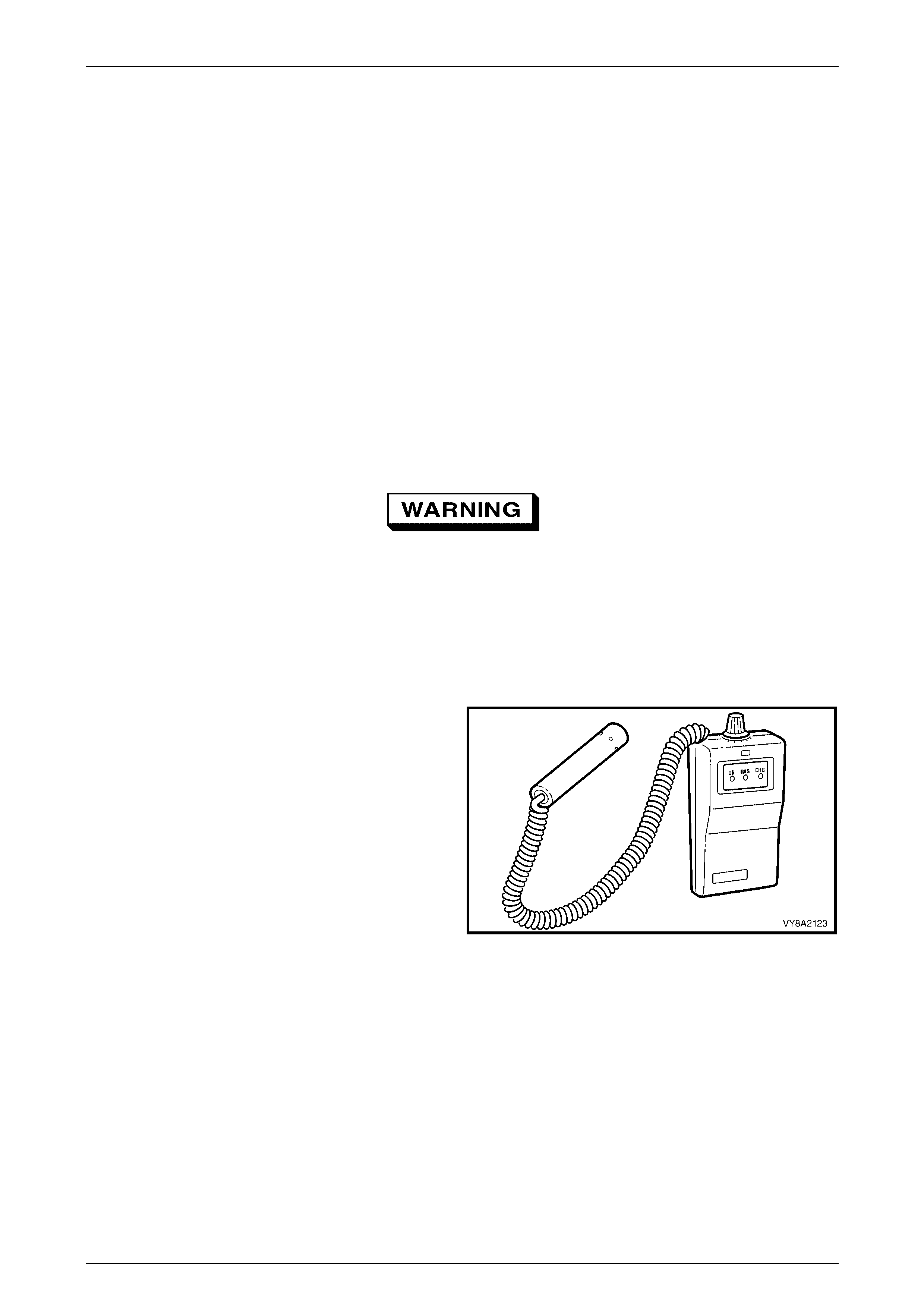
If a combustible gas detector is to be used for leak testing of
the LPG system, the combustible gas detector should be
capable of detecting 25 parts per million (PPM) of LPG in
air. A detector such as a LD-9001 LP Gas Leak Detector or
equivalent is r eco mm ende d.
Whichever leak detector is used, it is important to follow the
manufacturer's instructions in regard to adjustment and
setting the instrument prior to conducting the leak test.
Care in interpretation is necessary, as the detector can
respond to the presence of any of several vapours that are
combustible, some of which may not be LPG, such as oil
smears, joining compound s, et c. It may also dete ct resi dual
LPG vapours that are present for reasons other than
leakage, and which must be cleared before a valid test for
leakage can be made.
If a leak is present, a detector will signal its existence but
not its size, and will indicate its general location, but may not
be able to locate it exactly. A proving or follow up check with
foam is often desirable.
Figure 8A2 – 11
LPG System Page 8A2–13
Page 8A2–13
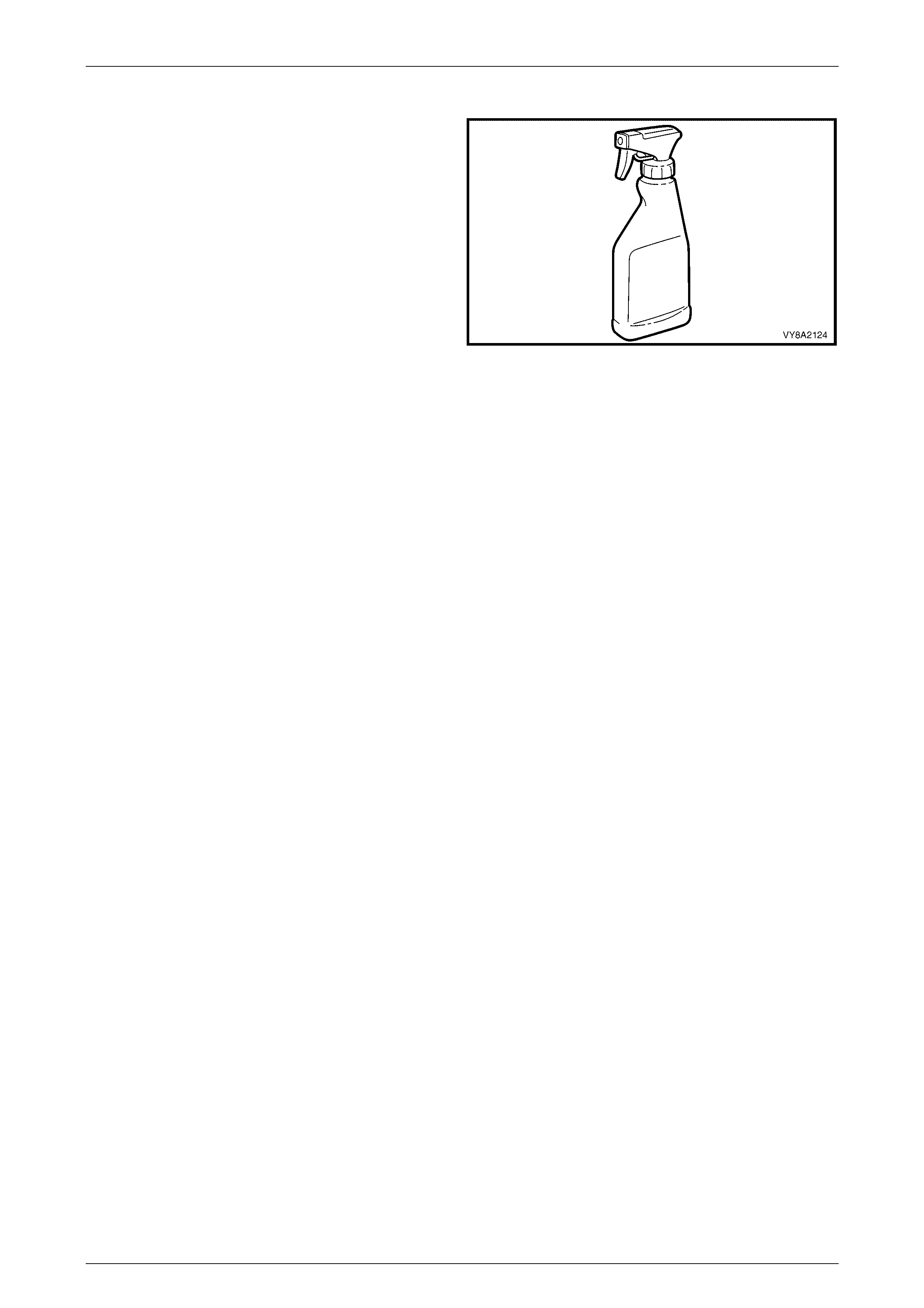
Foam
If foam is to be used, the foaming agent should be a
propriety leak test solution, formulated specifically for the
purpose, such as Gameco Leak Check TM or a similar
solution.
The solution should be fresh and the whole of the area to be
tested should be coated, and time allowed for bubbles to
form. All areas under test must be able to be observed
during the leak test.
Whichever foaming agent is used, it is important to follow
the manufacturer's instructions.
Foam testing is more effective for small leaks. Large leaks
tend to blow the solution away from the leak without forming
a bubble, so care in its application is necessary.
The leak test is performed by directing a spray of solution at
each of the possible leak points in the high-pressure side of
the system.
After applying the solution, look carefully for no less than 15
seconds.
A leak is indicated by the presence of gas bubbles (foaming)
in the solution at the leak source.
Figure 8A2 – 12
NOTE
LPG is heavier than air so thoroughly test below
all components and fittings. If a leak is detected
at a joint, the relevant component/s must be
removed as described in the appropriate service
operation in this Section. All mating threads must
be thoroughly cleaned, then resealed using the
specified sealant and tightened to the correct
torque specification. Once installed, thoroughly
leak test the component/s again.
At the completion of each test, dry the leak test area of the foaming agent with low-pressure compressed air or shop
cloths and spray the immediate area with a water-dispersing agent such as WD40 or RP7, etc.

LPG System Page 8A2–14
Page 8A2–14
Leak Test Procedure
Do not smoke or allow naked flames or any
ignition source near the vehicle during the
testing operations.
The leak test is to be performed in the open
air in a well-ventilated area, away from any
ignition source and prior to bringing the
vehicle into the workshop.
NOTE
If any leakage is detected during the leak test, the
leak is to be rectified and the leak test is to be
repeated.
NOTE
Ensure the vehicle is operating on LPG and run
the engine for at least 30 seconds to fully
pressurise the system, then stop the engine.
With 3 litres of LPG in the LPG tank, leak test the complete LPG system following the instructions.
1 Park the vehicle in a dry, well ventilated area.
2 Perform the following test sequence, referring to Figure 8A2 – 13 for locations.
LPG System Page 8A2–15
Page 8A2–15
Leak Test Locations
Figure 8A2 – 13

LPG System Page 8A2–16
Page 8A2–16
Legend
1 Pressure Relief Valve
2 AFL to LPG Tank
3 AFL Inlet Elbow to AFL
4 Filler Line to The AFL Inlet Elbow Connection
5 Tank Fuel Gauge Assembly
6 Manual Service Valve Assembly to LPG Tank
7 Manual Service V alve Assembl y
8 Rear Service Li ne to Manual Servic e Valve Assem bl y Elbow
Connection
9 Filler Valve Che c k Ball
10 Filler Line Connecting Pipe to Filler Line
11 Rear Service Li ne to Interm ediat e Service Line Joiner or
Elbow
12 Intermediate Service Line to Front Service Line Joiner
13 Front Service Line to Lock-off Inl et Connecti on
14 Lock-off Inlet Connec tion to Lock-off Valve
15 Lock-off Valve t o Lock-off Outlet Connecti on
16 Lock-off Outlet Connect i on to Converter
17 Lock-off Valve Assembly
18 Lock-off Valve Assembly
19 Lock-off Valve Assembly
20 Converter Mounting Faces
View A
Referring to the legend above and to Figure 8A2 – 13, remove the sub compartment cover and leak test at and around
the following locations:
1 Pressure relief valve.
2 AFL to LPG tank.
3 AFL inlet elbow to the AFL.
4 Filler line to the AFL inlet elbow connection.
5 Tank fuel gauge assembly.
6 Manual service valve assembly to the LPG tank.
7 Manual service valve assembly.
8 Rear service line to the manual service valve assembly elbow connection.
View B
Remove the right-hand quarter inner rear side carpet, refer to Section 1A8, 2.7 Quarter Inner Rear Side Carpet.
Open the fuel filler door and leak test at and around the following locations:
9 Filler valve check ball.
10 Filler line connecting pipe to the filler line.
View C
Raise the rear of the vehicle and support on safety stands, refer to Section 0A General Information for the location of
jacking points.
Leak test at around the following location:
11 Rear service line to intermediate service line joiner or elbow.
View D
Leak test the connection for the intermediate and front service lines located below the driver's door sill panel.
12 Intermediate service line to front service line joiner.
View E
Leak test in the engine compartment at and around the following points:
13 Front service line to lock-off inlet connection.
14 Lock-off inlet connection to lock-off valve.
15 Lock-off valve to lock-off outlet connection.
16 Lock-off outlet connect ion to conv erter.
LPG System Page 8A2–17
Page 8A2–17
17, 18, 19 Lock-off valve assembly.
20 Converter mounting faces.
If any leaks are detected at the completion of the leak test, close the manual service valve and drain the service line,
refer to Section 8A2, 3.1 Service Line Draining in the MY 2003 VY and V2 Series Service Information.
Switch to petrol and start the engine. The vehicle can now be driven into the workshop and any leaks rectified by
referring to the appropriate service proced ure s.
NOTE
The vehicle cannot be operated on LPG in the
workshop unless the workshop is a Specialist
Gas Workshop, refer to Australian Standard
AS 2746-1985.
Sub Compartment
The sub compartment including the vent hoses are incorporated into the system so that in the event any LPG escapes
from the tank fittings, pressure relief valve or the service line connection the LPG is allowed to vent to the atmosphere
and not into the passenger compartment of the vehicle. It is imperative that the sub compartment and hoses are checked
at regular intervals in accordance with AS 1425 – 1999.
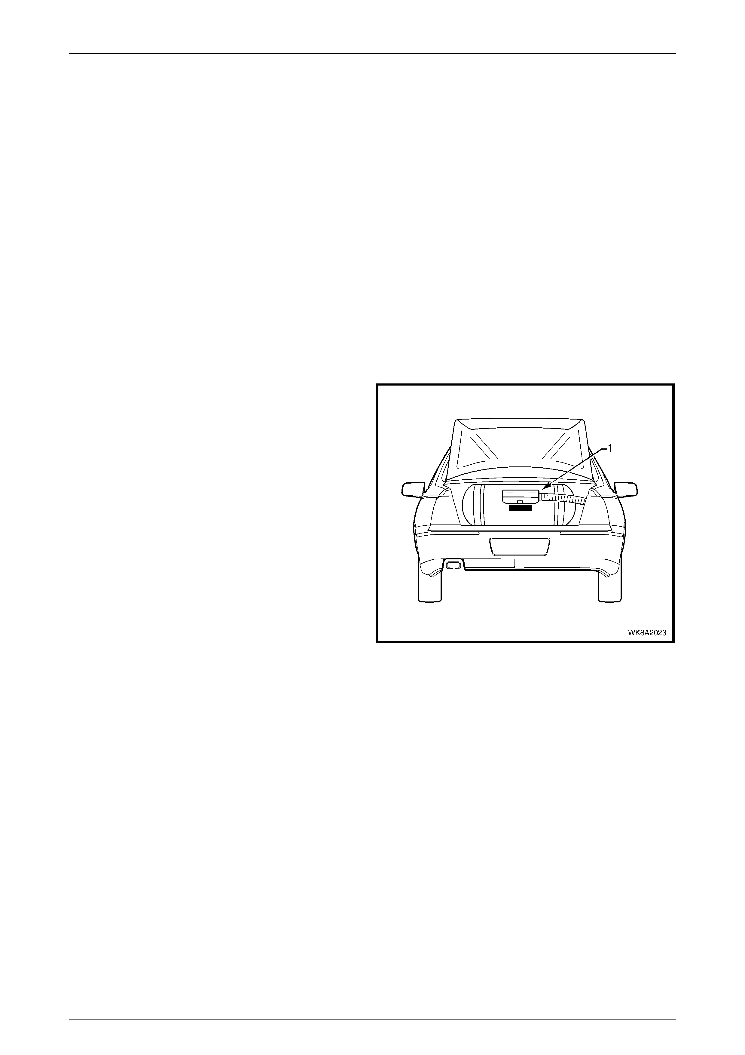
A compartment or sub compartment (1) shall be tested to
ensure that it is gastight to the vehicle interior by blowing
tracer gas into the compartment or sub compartment and
testing the surrounding atmosphere for gas leakage with a
combustible gas detector. Passages between the
compartment and the out side air such as ventilation
provisions or an access hatch or door of a permanently
inbuilt compartment, shall be sealed during testing.
If any leakage is detected, the leak shall be rectified and the
leak test is to be repeated.
Figure 8A2 – 14
LPG System Page 8A2–18
Page 8A2–18
2.4 Fuel Mode Switch
LT Section No. – AA-650Q
The test procedures for the fuel mode switch fitted to the MY 2004 WK Series Vehicles carries over from the MY 2003
VY Series, refer to Section 8A2, 3.22 Fuel Mode Switch in the MY 2003 VY and V2 Series Service Information.
Remove
1 If required, remove the navigation system remote control cradle and navigation monitor escutcheon, refer to
Section 12 L Naviga tion System.
2 Remove the floor console cover assembly, refer to Section 1A3, 2.1 Floo r Co nsole Cover Assembly in the MY 2003
VY and V2 Series Service Information.
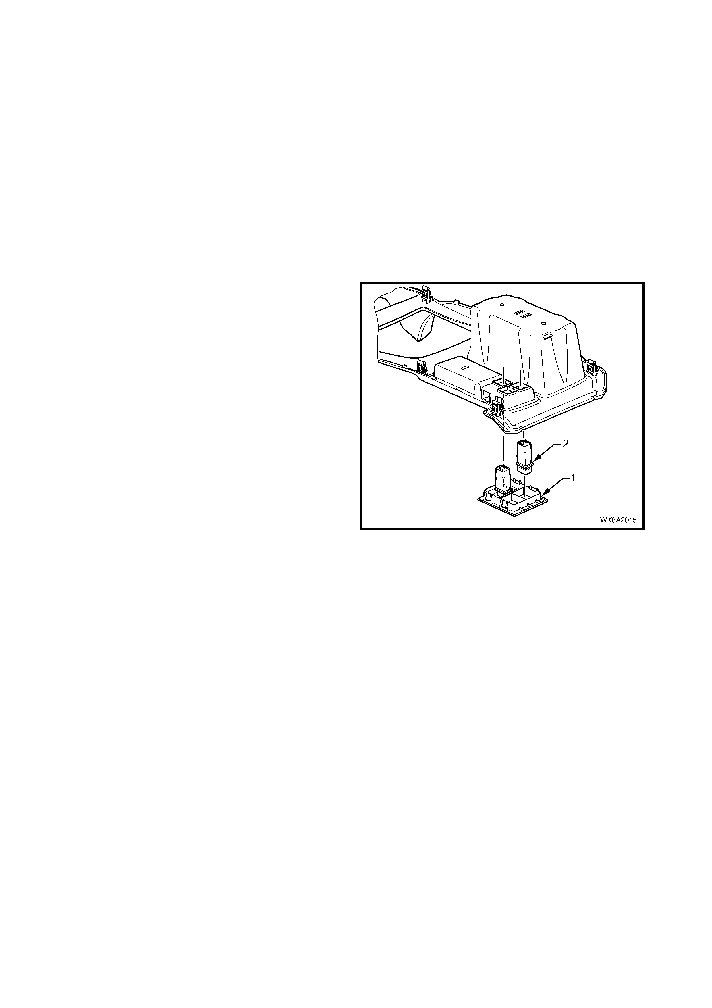
3. To remove the auxiliary switch bezel (1), depress the
four tabs attaching the auxiliary switch bezel to the
cover assembly and remove.
4. To remove the LPG switch (2), depress the two tabs
attaching the switch to the cover assembly and
remove the switch.
NOTE
The switches can only fit in the one location as
shown.
Figure 8A2 – 15
Reinstall
1. Reinstallation of the switch, bezel and console cover assembly is the reverse of the removal procedure.

LPG System Page 8A2–19
Page 8A2–19
3 Diagnosis
3.1 General Information
The procedures outlined in the LPG vehicle preliminary diagnostic chart must be carried out first whenever diagnosing a
problem in a LPG vehicle.
The LPG system is designed to operate in LPG mode when LPG has been selected via the fuel mode switch. W hen
diagnosing the LPG system, unless otherwise directed, ensure that LPG mode has been selected, there is LPG in the
LPG tank and the manual service valve is turned on.
When LPG has been selected via the fuel mode switch, the PCM will operate in LPG mode if the operating parameters
sensed by the PCM permit the switching to the LPG mode.
Before any diagnostic procedures are carried out on the LPG system, ensure the vehicle operates on petrol without any
problems.
For diagnosis of the LPG fuel gauge and the LPG instrument cluster display icons, refer to Section 12C Instrument
Cluster.

LPG System Page 8A2–20
Page 8A2–20
3.2 Prerequisites to Diagnosis and
Troubleshooting
Preliminary System Requirements
Ensure that sound earth connections are provided for all functioning components, particularly at the body earth
connection (fender panel inner stud, adjacent to the battery).
Ensure the battery is in good condition and adequately charged (above 12.5 volts) before carrying out any electrical
checks.
Safety Requirements
Disconnection of the battery affects
certain vehicle electronic systems. Refer to
Section 00, 6 Battery Disconnection
Procedures.
Disconnect the battery when carrying out work which can involve the risk of an electrical short circuit.
Do not touch mechanical components during function checks, to avoid the risk of a hand being caught in the mechanism.
All Safety Standards and Regulations pertaining to LPG must be followed at all times, refer to 2.1 Safety Precautions.
Checking Equipment
• Tech 2 scan tool.
For information on Tech 2 connection and operation procedures, refer to Section 0C Tech 2.
• A digital multimeter, with a minimum 10 Mega-ohm impedance must be used when undertaking any electrical
checks on these sy ste ms.
• Exercise care when taking readings from wiring harness connectors. It is preferred that the back probing method
with individual connectors is employed wherever possible, to avoid terminal damage and subsequent connection
failure.
• When carrying out wiring checks as directed to by the diagnostic charts, rather than probe terminals and
connectors with incorrect sized multimeter connections, use the adapters contained in connector test adapter kit
KM-609. This will prevent any possibility of spreading or damaging wiring harness terminals.
NOTE
Ensure that the ignition is turned off and the
battery earth lead is disconnected before any test
that requires the disconnection or connection of
any control mod ule con ne ctor s .
• When checking the complete system, the exact order of the test steps should be observed.
• If the required nominal value is not achieved in any stage, then the problem must be rectified before proceeding
further.
• Unless the multimeter being used has an auto ranging function, check that the correct range, as specified, is
selected before the test is carried out.
Testing of the system will involve gaining access to specific wiring harness connectors. For the location of connectors not
detailed in this Section, refer to Section 12O Fuses, Relays and Wiring Harnesses.

LPG System Page 8A2–21
Page 8A2–21
3.3 LPG Vehicle Preliminary Diagnosis
Test Description
The numbers below refer to step numbers in the following diagnostic chart.
1 Ensures Tech 2 is functioning correctly.
2 Checks if Tech 2 can communicate with the PCM.
3 Checks if any PCM DTCs are present.
4 Checks if the PCM can operate in the LPG mode.
5 Checks if the LPG switch is operating correctly.
6 Checks the operation of the LPG icon.
7 Checks if the engine will operate on petrol.
8 Checks if the engine will crank when LPG has been selected.
9 Checks if the engine will run when LPG has been selected.
10 Checks for engine backfiring.
11 Checks for engine performance.
12 Checks fuel gauge operation.
Test Procedure
Step Action Yes No
1 1. Turn ignition off, connect Tech 2 to DLC, turn ignition on and
Tech 2 on.
2. Does Tech 2 power-up (screen will illuminate and display Tech
2)?
Go to Step 2. Refer to Tech 2
Diagnosis in,
Section 0C.
2 1. With Tech 2 still connected and ignition on, press the ENTER
key then select F0: Diagnostics / (3) 2004 / WK / F0: Engine /
V6 and then follow the screen instructions.
2 Does Tech 2 display PCM identification information?
Go to Step 3. Refer to On-
Board
Diagnostic
System Check
in Section 6C1.
3 1 At the Tech 2 PCM Identification screen, press the Confirm soft
ke y. From the Engine menu select F1: Diagnostic Trouble
Codes / F0: Read Current DTC.
2 Are any DTCs present?
Refer to On-Board
Diagnostic
System Check in
Section 6C1.
Go to Step 4.
4 1. Return to the Tech 2 Engine menu and select F2: Data Display
/ F0: All Data / Scroll to LPG Fuel Enabled.
2. Does Tech 2 display LPG Fuel Enabled YES?
Go to Step 5. Refer to
3.4 Vehicle
Does Not
Operate On
LPG.
5 1. With Tech 2 still connected, scroll to Fuel.
2. Select LPG via the fuel mode switch.
3. Does Tech 2 Data parameter Fuel change from Petrol to LPG?
Go to Step 6. Refer to
3.5 Fuel Mode
Switch Does
Not Operate.
6 1 With the LPG Mode selected.
(Tech 2 Data parameter Fuel displaying LPG).
2. Is the LPG icon illuminated in the instrument cluster?
Go to Step 7. Refer to
Section 12C
Instruments.

LPG System Page 8A2–22
Page 8A2–22
Step Action Yes No
7 1. Select Petrol via the fuel mode switch.
2. Will the engine crank and start immediately the ignition key is
turned from off to start (no delay)?
Go to Step 8. Refer to On-
Board
Diagnostic
System Check
in Section 6C1.
8 1. Select LPG via the fuel mode switch.
2. Will the engine crank immediately the key is turned from off to
start (no delay)?
Go to Step 9. Refer to
3.6 Engine
Does Not
Crank.
9 1. Does the engine start and run on LPG? Go to Step 10. Refer to
3.7 Engine
Cranks But Will
Not Start On
LPG.
10 1. Does the engine backfire when operated on LPG? Refer to 3.8
Engine Backfires
On LPG.
Go to Step 11.
11 1 Does engine lack power, sluggish or have poor performance
when operating on LPG? Refer to 3.9 Poor
Performance, Flat
Spotting, Sluggish
Or Poor Fuel
Consumption.
Go to step 12.
12 1 Does fuel gauge operate correctly? LPG Diagnostic
Check completed. Refer to
Section 12C
Instruments.
When all diagnosis and repairs are complete, verify correct operation.

LPG System Page 8A2–23
Page 8A2–23
3.4 Vehicle Does Not Operate on LPG
Test Description
The numbers below refer to step numbers in the following diagnostic chart.
1 The LPG Vehicle Preliminary Diagnosis Check must be the first step when diagnosing any LPG system problem.
2 The PCM will not operate in the LPG mode if the PCM has not been programmed to operate on LPG. Refer to the
latest technical publications for the correct PROM application.
3 When the ignition is turned on, battery voltage is applied to terminal X3_F16 of the PCM. This enables the PCM to
operate in either the Petrol or LPG mode. If battery voltage is not applied to PCM terminal X3_F16 the PCM will
only operate in the Petrol mode.
4 This test confirms that the PCM connector terminal retention is not causing the problem. The terminal retention
should always be checked before a PCM is replaced.
Test Procedure
Refer to Figure 8A2 – 16 for test point locations.
Step Action Yes No
1 1 Has the LPG Vehicle Preliminary Diagnosis Check been
performed? Go to step 2 Perform LPG
Vehicle
Preliminary
Diagnosis
Check.
2 1 Has the PCM been programmed for LPG operation?
Go to step 3. Perform SPS to
program the
PCM for LPG
oper ati on. Refer
to SPS in
Section 0C
Tech 2.
3 1 Ignition on.
2 Measure the voltage at PCM connector A84 terminal X3_F16
(Grey/Pink wire).
3 Is battery voltage present?
Go to step 4. Check LPG
fuse or repair
open circuit .
4 1 Check PCM connector terminal retention.
If retention OK replace PCM.
2 Is terminal retention OK?
Replace PCM.
Verify repair. Repair
terminals.
Verify repair.
When all diagnosis and repairs are complete, verify correct operation.
LPG System Page 8A2–24
Page 8A2–24
Figure 8A2 – 16

LPG System Page 8A2–25
Page 8A2–25
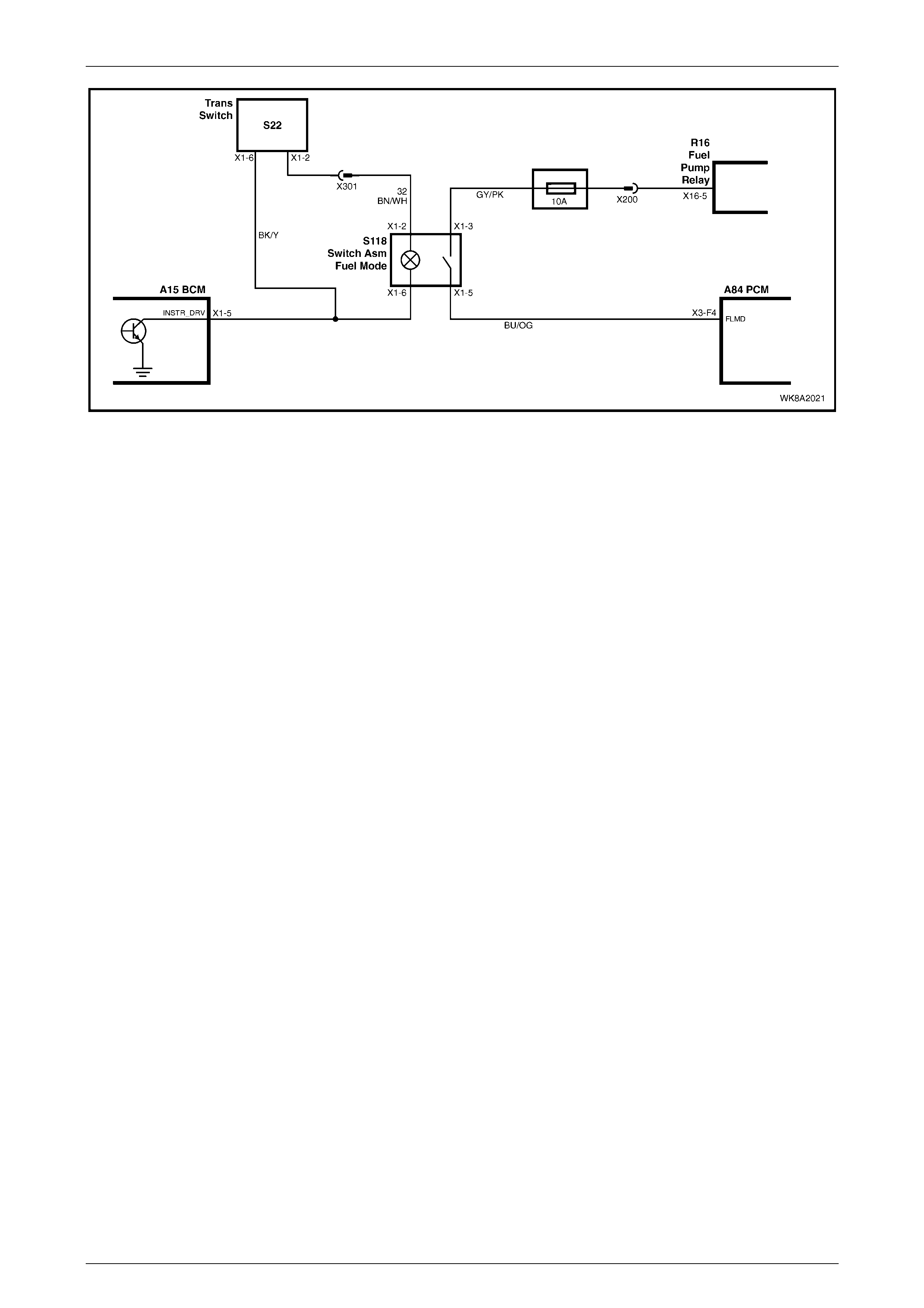
3.5 Fuel Mode Switch Does Not Operate
Test Description
The numbers below refer to step numbers in the following diagnostic chart.
1 The LPG vehicle preliminary diagnosis check must be the first step when diagnosing any LPG system problem.
2 Checks for battery voltage when the fuel mode switch is activated.
3 Checks for voltage at the fuel mode switch. If voltage is not present the circuit is open between the fuel mode
switch and the ignition switch. If a voltage is present there is an open circuit between the fuel mode switch and
PCM terminal X3_F4.
4 Tests operation of fuel mode switch.
5 This test checks for an open circuit in the fuel mode switch circuit between the fuel mode switch and PCM terminal
X3_F4.
6 This test confirms that the PCM connector terminal retention is not causing the problem. The terminal retention
should always be checked before a PCM is replaced.
Test Procedure
Refer to Figure 8A2 – 17 for test point locations.
Step Action Yes No
1 1 Has the LPG Vehicle Preliminary Diagnosis Check been
performed? Go to step 2 Perform LPG
Vehicle
Preliminary
Diagnosis
Check.
2 1 Ignition On
2 Measure the voltage at PCM terminal X3_F4.
(Blue/Orange wire)
3 Is battery voltage present when the fuel mode switch is
depressed?
Go to step 6. Go to step 3.
3 1 Ignition on.
2 Measure the voltage at the fuel mode switch connector X1-3
(Grey/Pink wire).
3 Is battery voltage present?
Go to step 5. Check LPG
fuse or repair
the open circuit.
4 1 Test the fuel mode switch, refer to Section 8A2, 3.22 Fuel
Mode Switch in the MY 2003 VY and V2 Series Service
Information.
2 Is the fuel mode switch OK?
Go to step 4. Replace fuel
mode switch.
Verify repair.
5 1 Check for open circuit (Blue/Orange wire) between the fuel
mode switch and PCM terminal X3_F4.
2 Is circuit open?
Repair open in
circuit Verify
repair.
Go to step 6.
6 1 Check PCM connector terminal retention.
2 Is terminal retention OK?
Replace PCM.
Verify repair. Repair
terminals.
Verify repair.
When all diagnosis and repairs are complete, verify correct operation.
LPG System Page 8A2–26
Page 8A2–26
Figure 8A2 – 17

LPG System Page 8A2–27
Page 8A2–27
3.6 Engine Does Not Crank
Test Description
The numbers below refer to step numbers in the following diagnostic chart.
1 The LPG Vehicle Preliminary Diagnosis Check must be the first step when diagnosing any LPG system problem.
2 The theft deterrent system must be disarmed before the engine will crank. If the Theft Deterrent System cannot be
disarmed, refer to Theft Deterrent Diagnostics in Section 12J BCM.
3 When petrol is selected, the engine should crank immediately the ignition switch is turned from off to start. If the
engine does not crank immediately, then refer to Section 6C1 On-Boar d Diagnostic System Check.
4 When LPG is selected, the engine should crank immediately the ignition switch is turned from off to start. If the
engine cranks immediately system is operating correctly.
5 When LPG is selected, the PCM will prevent the engine from cranking if the PCM determines the throttle is open
more than 7%. This test uses Tech 2 to monitor the throttle position sensor operation.
Test Procedure
Step Action Yes No
1 1. Has the LPG Vehicle Preliminary Diagnosis Check been
performed? Go to step 2 Perform the
LPG Vehicle
Preliminary
Diagnosis
Check.
2 1. Ignition on.
2. Is theft deterrent system disarmed?
(Theft deterrent status indicator in the instrument cluster not
flashing or illuminated).
Go to Step 3. Refer to
Section 12J
BCM.
3 1 Ignition on.
2 Select Petrol via the fuel mode switch.
3. Turn ignition switch from OFF to START positions for a
maximum of five seconds or until engine starts to crank.
4. Does engine crank immediately (less than one second)?
Go to Step 4. Refer to
On-Board
Diagnostic
System Check,
Section 6C1.
4 1 Ignition on.
2 Select LPG via the fuel mode switch.
3 Turn ignition switch from OFF to START for a maximum of five
seconds or until engine starts to crank.
4 Does engine crank immediately (less than one second)?
System operating
correctly.
Check for
intermittent
connections.
Go to Step 5.
5 1 Turn ignition off.
2 Connect Tech 2 to the DLC.
3 Turn ignition on and then turn Tech 2 on.
4 At the engine menu select F2: Data Display / F0: All Data.
5 Scroll to Throttle Position Sensor.
6 Is Throttle Position sensor displaying 0%?
Refer to On-Board
Diagnostic
System Check,
Section 6C1.
Refer to TP
Sensor Output
Chec k in
Section
6C1-2A.
When all diagnosis and repairs are complete, verify correct operation.

LPG System Page 8A2–28
Page 8A2–28
3.7 Engine Cranks But Will Not Start on LPG
Test 1 Description
The numbers below refer to step numbers in the following diagnostic chart.
1 The LPG vehicle preliminary diagnosis check must be the first step when diagnosing any LPG system problem.
2 These initial checks are designed to verify that the engine is capable of operating on LPG.
3 Voltage is supplied to the LPG lock-off from the smart unit when the ignition is first turned on and when the engine
is cranking or running. If voltage is not present at these times, the lock-off will not be energised and LPG will not
flow to the converter.
4 This test confirms correct converter operation. Incorrect converter pressures can cause the engine not to start.
5 This test determines if the PCM is causing the no start condition.
6 Vacuum leaks or blockages can cause a variety of system operating problems. All hoses and vacuum lines should
be checked.
7 This test confirms correct mixer operation.
8 This test confirms correct PCM LPG set up.
Test Procedure
Step Action Yes No
1 1. Has the LPG Vehicle Preliminary Diagnosis Check been
performed? Go to step 2. Perform the
LPG Vehicle
Preliminary
Diagnosis
Check.
2 Initial che ck s:
1. Has LPG been selected via the fuel mode switch?
2. Has the PCM been programmed to operate on LPG?
3. Is the manual service valve open?
4. Is there any LPG present in the LPG tank, check contents
gauge?
If yes to all, go to
Step 3. Repai r an y
faults. Recheck
starting on LPG.
3 1. Measure the voltage at LPG lock-off connector
at the front of the vehicle (Blue/Black wire).
2. Is voltage above nine volts for three seconds when the ignition
is first turned on or while the engine is cranking?
Go to Step 4. Go to
Diagnostic
Chart Engine
Cranks But Will
Not Start On
LPG (Test 2).
4 1. Test for presence of LPG in the system by checking converter
pressures, refer to Section 8A2, 3.18 Converter in the MY 2003
VY and V2 Series Service Information
2. Are converter pressures OK?
Go to Step 5. Go to
Diagnostic
Chart Engine
Cranks But Will
Not Start On
LPG (Test 3).
5 1. Ignition on, select Petrol via the fuel mode switch.
2. Start engine and bring to 2000 RPM.
3. Select the LPG mode via the fuel mode switch.
4. Does the engine continue to run?
Set-up LPG
System. Refer to
2.2 LPG Set-up
Procedure in the
MY 2004 VY and
V2 Series Service
Information.
Recheck starting
on LPG.
Go to Step 6.

LPG System Page 8A2–29
Page 8A2–29
Step Action Yes No
6 1. Check for vacuum leaks or incorrect routing in the vacuum or
vapour feed lines between the mixer and converter, or a
blocked balance line, FCV or RCV.
2. Are there any leaks, incorrect routing or blockages?
Repair vacuum
leaks or
blockages.
Recheck starting
on LPG.
Go to Step 7.
7 1. Test mixer operation, refer to 3.21 Mixer in the MY 2003 VY
and V2 Series Service Information, noting that if the mixer is
faulty it will require replacement as a complete assembly.
2. Is mixer operating correctly?
Go to Step 8. Check and
repair any air
leaks between
mixer and
throttle body, if
there are no
leaks, replace
the mixer. Refer
to 2.1 Mixer in
the MY 2004
VY and V2
Series Service
Information.
Recheck
starting on LPG.
8 1. Perform the LPG set-up procedure, refer to 2.2 LPG Set-up
Procedure in the MY 2004 VY and V2 Series Service
Information. Re che ck star ting on LPG.
2. Does engine start on LPG?
System OK. Go to
Diagnostic
Chart Engine
Cranks But Will
Not Start On
LPG (Test 2).
When all diagnosis and repairs are complete, verify correct operation.

LPG System Page 8A2–30
Page 8A2–30
Test 2 Description
Refer to Figure 8A2 – 19 for the following test point locations.
The numbers below refer to step numbers in the following diagnostic chart.
1 This test checks that the smart unit is supplying voltage.
2 This test checks if the circuit to the front solenoid is shorted to earth.
NOTE
The smart unit has a current protection device on
this circuit. If the circuit is shorted to earth the
smart unit will shutdown. The ignition must be
cycled from on to off to reset the smart unit.
3 This test checks continuity of the smart unit earth circuit.
4 This test checks that voltage is being applied to the smart unit in the anti-theft circuit.
5 Ignition voltage should be present at PCM terminal X3_F16 whenever the ignition is on.
6 When operating in the LPG mode, the PCM pulses the 12 volt pull-up in the smart unit to earth at a 50% duty cycle.
Therefore the voltage at PCM terminal X1_A3 should be approximately five volts when the ignition is first turned on
or when the engine is cranking.
7 This test checks the continuity of the circuit from PCM pin X1_A3 to the smart unit (White/Green wire) in the
anti-theft cir cuit .
8 This test checks if the anti-theft circuit (W hite/Green wire) is shorted to earth.
Test Procedure
Step Action Yes No
1 1. Ignition ON, LPG selected.
2. Measure the voltage at the fuel sender & pump control module
(smart unit) connector X1_5 (Blue/Black wire).
3. Is voltage above nine volts for three seconds when the ignition
is first turned on or while the engine is being cranked?
Repair open
circuit in the LPG
lock-off circui t
between the smart
unit and lock-off.
Recheck starting
on LPG.
Go to Step 2.
2 1 Check for short to earth in LPG lock-off circuit, between the
Smart Unit connector X1_5 and the lock-off (Blue/Black wire).
2 Is the circuit shorted to earth?
Repair short to
earth in the LPG
lock-off circui t
between the smart
unit and lock-off.
Recheck starting
on LPG.
Go to step 3.
3 1. Check contin uity of the smart unit earth circuit (Black/R ed w ire)
between the smart unit connector X1_1 and a known good
earth.
2. Is there continuity?
Go to step 4. Repair open in
the circuit
(Black/Red)
wire. Recheck
starting on LPG.
4 1. Ignition ON.
2. Measure the voltage at the smart unit connector X1_6
(Pink wire).
3. Is battery voltage present?
Go to Step 5. Repair open in
the circuit
(Pink wire)
between the
fuse and the
smart unit.

LPG System Page 8A2–31
Page 8A2–31
Step Action Yes No
5 1 Ignition ON.
2 Measure the voltage at PCM connector A84_X3 terminal F16
(Grey/Pink wire).
3 Is battery voltage present?
Go to step 6. Repair open in
the circuit
between the
Ignition sw itch
and PCM
(Grey/Pink wire)
Recheck
starting on LPG.
6 1 With LPG selected via the fuel mode switch.
2 Disconnect the smart unit connector.
3 Measure the voltage at the smart unit connector X1_2 circuit
on the PCM side (White/Green wire).
4 Turn the ignition from OFF to ON. Is, voltage approximately
five volts for three seconds when the ignition is first turned on
or when the engine is cranking?
Check the smart
unit connector
terminal retention.
If OK, replace
smart unit.
Verify repair.
Go to step 7.
7 1 With LPG selected via the fuel mode switch.
2 Measure the voltage at the PCM connector A84_X1 terminal
A3 PCM side (White/Green wire).
3 Turn the ignition from OFF to ON, is voltage approximately five
volts for three seconds when the ignition is first turned from off
to on or when the engine is cranking?
Go to step 8. Check PCM
connector
terminal
retention. If OK,
replace PCM.
Recheck
starting on LPG.
8 1. Check for continuity of the circuit between the smart unit
connector and PCM connector A84_X3 terminal A3
(White/Green wire).
2. Is there continuity?
Go to step 9. Repair open in
the circuit
(White/Green
wire). Verify the
repair.
9 1. Check for a short to earth in the circuit between the smart unit
connector and PCM connector A84_X1 terminal A3
(White/Green wire).
2. Is there a short to earth?
Repair short to
earth in the circuit
(White/Green
wire).
Verify the repair.
Check the PCM
connector
terminal
retention. If OK,
replace PCM.
Recheck
starting on LPG.
When all diagnosis and repairs are complete, verify correct operation.

LPG System Page 8A2–32
Page 8A2–32
Test 3 Description
The numbers below refer to step numbers in the following diagnostic chart.
1 Low primary converter pressure can be caused by a low supply pressure or a faulty converter.
2 If the primary converter pressure is too high the converter will have to be overhauled.
3 If the primary converter pressure is within specification but the secondary converter pressure is out of specification
the converter will have to be overhauled.
4 This test checks if the solenoid valve is restricting the flow of LPG.
5 This test checks the flow of LPG from the LPG tank to the LPG lock-off.
6 This test determines if the LPG lock-off or the converter is causing the problem.
7 This test checks if the service line is blocked. If the service line is not blocked then the manual service valve or the
LPG cylinder pick up must be blocked.
Test Procedure
Step Action Yes No
1. 1. Check the primary converter pressure, refer to Section 8A2,
3.18, Converter in the MY 2003 VY and V2 Series Service
Information.
2 Is primary converter pressure below specification?
Go to Step 4. Got to Step 2.
2. 1. Is primary converter pressure above specification? Repair the
converter, refer to
Section 8A2, 3.18
Converter in the
MY 2003 VY and
V2 Series Service
Information.
Recheck starting
on LPG.
Go to Step 3.
3. 1. If primary converter pressure is within specification, check the
secondary converter pressure, refer to Section 8A2, 3.18,
Converter in the MY 2003 VY and V2 Series Service
Information.
2 Is the secondary converter pressure out of specification?
Repair convert er,
refer to
Section 8A2, 3.18
Converter in the
MY 2003 VY and
V2 Series Service
Information.
Recheck starting
on LPG.
Go to step 4.
4. 1. Ignition OFF.
2. Close manual service valve.
3. Remove the solenoid sleeve and valve from the manual
service valve assembly and reinstall the solenoid sleeve
without the solenoid valve, refer to Section 8A2, 3.8 Smart Unit
and Solenoid Valve in the MY 2003 VY and V2 Series Service
Information.
4. Does engine start and run on LPG?
Replace the smart
unit and solenoid
valve.
Recheck starting
on LPG.
Go to Step 5.

LPG System Page 8A2–33
Page 8A2–33
Step Action Yes No
5. 1. Ignition OFF.
2. Close the manual servi ce valv e and ensure the serv ic e line is
drained of LPG, refer to Section 8A2, 3.1, Service Line
Draining in the MY 2003 VY and V2 Series Service
Information.
3. With the solenoid valve still removed from the manual service
valve assembly as in step 4.
The following operation must be performed by,
trained and/or licensed LPG installers or fitters in
accordance with Australian Standards AS 2746-1999
and AS 1425-1999.
4. Disconnect the front service line at the LPG lock-off.
5. In accordance with AS-1425 – 1999, have a second technician
slowly open the manual service valve so that the excess flow
valve doesn’t shut LPG flow off .
NOTE
If a click is herd at the manual service valve, the excess
flow valve has closed.
6. Does LPG flow from the front service line?
Go to Step 6. Go to Step 7.
6. 1. Test LPG lock-off, refer to Section 8A2, 3.17 LPG Lock-off in
the MY 2003 VY and V2 Series Service Information.
2. Is LPG lock-off OK?
Repair convert er,
refer to Section
8A2, 3.18
Converter in the
MY 2003 VY and
V2 Series Service
Information.
Recheck starting
on LPG.
Repair LPG
lock-off, refer to
Section 8A2,
3.17 LPG Lock-
off in the
MY 2003 VY
and V2 Series
Service
Information.
Recheck
starting on LPG.
7. 1. Disconnect the rear service line at the manual service valve.
2. With front service line still disconnected, blow air through
service line to check for blockages
3. Does air flow through service line?
Check for manual
service valve or
LPG tank fuel
pick-up blockage
or fault. Repair or
replace blocked or
damaged
components.
Recheck starting
on LPG.
Check for
damaged or
blocked service
lines. Repair or
replace blocked
or damaged
components.
Recheck
starting on LPG.
When all diagnosis and repairs are complete, verify correct operation.

LPG System Page 8A2–34
Page 8A2–34
3.8 Engine Backfires on LPG
Test Description
The numbers below refer to step numbers in the following diagnostic chart.
NOTE
Whenever an engine backfire has occurred, the
complete intake system including the mixer
should be checked for damage.
1 The LPG Vehicle Preliminary Diagnosis Check must be the first step when diagnosing any LPG system problem.
2 An On Board Diagnostic System Check should be performed to confirm that a problem with the powertrain
management system is not causing the engine to backfire when operating on LPG.
3-7. An ignition system that is not operating at it’s full potential can cause an engine to backfire when operating on LPG.
Ignition leads that operate quite well when operating on petrol, can cause problems when operating on LPG.
Therefore, all ignition system components must be at here optimum when operating on LPG.
8 Vacuum leaks or blocked vacuum lines can cause incorrect system operation, causing engine backfire.
9 Incorrect mixer operation can cause incorrect air/fuel ratios. Incorrect air/fuel ratios can cause engine backfire.
10 Incorrect LPG set-up can cause incorrect system operation, causing engine backfire.
11 Incorrect converter operation can cause incorrect air/fuel ratios. Incorrect air/fuel ratios can cause engine backfire.
12 This test confirms correct regulator check valve (RCV) operation, incorrect RCV operation can cause slow
converter response causing engine backfire.
13 Engine mechanical condition can cause engine operating problems that do not affect the engine when operating on
petrol. The engine must be in optimum operating condition to prevent the engine backfiring when operating on
LPG.
Test Procedure
Step Action Yes No
1 1. Has the LPG Vehicle Preliminary Diagnosis Check been
performed? Go to step 2 Perform the
LPG Vehicle
Preliminary
Diagnosis
Check.
2 1 Has an On Board Diagnostic System Check been performed? Go to Step 3. Perform On-
Board
Diagnostic
System Check.
Refer to Section
6C1.
Recheck for
engine backfire.
3 1. Check spark plug leads for tracking or cracks in insulation and
check their resistance, refer to Section 6D1-3
Ignition System -V6.
2. Are the spark plugs leads OK?
Go to Step 4. Replace spark
plug leads.
Recheck for
engine backfire.
4 1. Remove and inspect spark plugs for fouling.
2. Are the spark plugs OK?
Go to Step 5. Replace spark
plugs. Recheck
for engine
backfire.

LPG System Page 8A2–35
Page 8A2–35
Step Action Yes No
5 1. Re-gap spark plugs to minimum specification.
2. Have spark plugs been re-gaped to minimum specification?
Go to Step 6. Re-gap spark
plugs to
minimum
specification.
Recheck for
engine backfire.
6 1. Check ignition coil resistance, refer to Section 6D1-3 Ignition
System - V6.
2. Is the ignition coil resistance within specification?
Go to Step 7. Replace faulty
ignition co il.
Recheck for
engine backfire.
7 1. Check PCM, DIS and crank angle sensor wiring harness
terminal retention.
2. Is terminal retention OK?
Go to Step 8. Resize
terminals.
Recheck for
engine backfire.
8 1. Check for vacuum leaks in vacuum or vapour feed lines
between mixer and converter, or a blocked balance line, FCV
or RCV.
2. Are there any leaks or blockages?
Repair vacuum
leaks or
blockages.
Recheck for
engine backfire.
Go to Step 9.
9 1. Test mixer operation, refer to 3.21 Mixer in the MY 2003 VY
and V2 Series Service Information, noting that if the mixer is
faulty it will require replacement as a complete assembly.
2. Is the mixer operating correctly?
Go to Step 10. Replace the
mixer, refer to
2.1 Mixer in the
MY 2004 VY
and V2 Series
Service
Information.
Recheck for
engine backfire.
10 1. Is the LPG set-up correct? Go to Step 11. Perform the
LPG set-up
procedure refer
to 2.2 LPG
Set-up
Procedure in
the MY 2004
VY and V2
Series Service
Information.
Recheck for
engine backfire.
11 1. Test converter pressures.
2. Are the converter pressures OK?
Go to Step 12. Overhaul the
converter, refer
to Section 8A2,
3.18 Converter
in the MY 2003
VY and V2
Series Service
Information.
12 1. Test regulator check valve operation, refer to Section 8A2,
3.19 Regulator Check Valve in the MY 2003 VY and V2 Series
Service Information.
2. Is Regulator Check Valve operating correctly?
Go to Step 13. Replace the
regulator check
valve, refer to
Section 8A2,
3.19 Regulator
Check Valve in
the MY 2003
VY and V2
Series Service
Information.
Recheck for
engine backfire.

LPG System Page 8A2–36
Page 8A2–36
Step Action Yes No
13 1. Check the engine me cha nic al cond ition by checking
compressi on, valve t iming, intake and ex haust valv es and
manifolds for casting flash.
2. Is the engine mechanical condition OK?
Check for
incorrectly routed
harnesses,
ignition lea ds
or non genuine
accessories.
Repai r an y
faults. Recheck
for engine
backfire.
When all diagnosis and repairs are complete, verify correct operation.

LPG System Page 8A2–37
Page 8A2–37
3.9 Poor Performance, Flat Spotting,
Sluggish or Poor Fuel Consumption
NOTE
Due to the nature of LPG, a minimal loss of
power may be experienced under heavy
acceleratio n, this is expected and quite normal.
Test Description
The numbers below refer to step numbers in the following diagnostic chart.
1 The LPG Vehicle Preliminary Diagnosis Check must be the first step when diagnosing any LPG system problem.
2 An On Board Diagnostic System Check should be performed to confirm that a problem with the powertrain
management system is not causing the engine to backfire when operating on LPG?
3 This checks for common causes of engine drivability problems.
4 Incorrect LPG set-up can cause incorrect air/fuel ratios.
5 Correct mixer operation is required so that the correct air/fuel ratio is achieved.
6 A regulator check valve that is blocked or opening at the wrong vacuum can cause incorrect converter operation.
7 The converter is one of the key components in the control of the delivery of LPG. Incorrect converter operation can
cause rich or lean mixtures.
8 Poor engine mechanical condition can cause poor performance, sluggish or poor fuel consumption. The engine
must be in a good operating condition for optimum performance when operating on LPG.
Test Procedure
Step Action Yes No
1 1. Has the LPG Vehicle Preliminary Diagnosis Check been
performed? Go to step 2 Perform the
LPG Vehicle
Preliminary
Diagnosis
Check.
2 1 Has an On Board Diagnostic System Check been performed? Go to Step 3. Perform On-
Board
Diagnostic
System Check,
refer to Section
6C1.
Recheck
performance.
3 1. Perform Symptoms Check, refer to Section, 6C1.
2. Are all checks OK?
Go to Step 4. Repair any
faults. Recheck
performance.
4 1. Has the LPG set-up procedure been performed? Go to Step 5. Perform the
LPG set-up
procedure, refer
to 2.2 LPG
Set-Up
Procedure in
the MY 2004
VY and V2
Series Service
Information.
Recheck
performance.

LPG System Page 8A2–38
Page 8A2–38
Step Action Yes No
5 1 Test mixer operation, refer to 3.21 Mixer in the MY 2003 VY
and V2 Series Service Information, noting that if the mixer is
faulty it will require replacement as a complete assembly.
2. Is Mixer operating correctly?
Go to Step 6. Replace the
mixer, refer to
2.1 Mixer in the
MY 2004 VY
and V2 Series
Service
Information.
Recheck
performance.
6 1. Test the regulator check valve (RCV) operation, refer to
Section 8A2, 3.19 Regulator Check Valve in the MY 2003 VY
and V2 Series Service Information.
2. Is the RCV operating correctly?
Go to Step 8. Replace the
regulator check
valve.
Recheck
performance.
7 1. Test converter operation, refer to Section 8A2, to 3.18
Converter in the MY 2003 VY and V2 Series Service
Information.
2. Is converter operating correctly?
Repair the
converter, refer
to Section 8A2,
to 3.18
Converter in the
MY 2003 VY
and V2 Series
Service
Information.
Recheck
performance.
8 1. Check the engine me cha nic al cond ition by checking
compressi on, valve t iming, intake and ex haust valv es and
manifolds for casting flash.
2. Is the engine mechanical condition OK?
Repair any
faults. Recheck
performance
and fuel
economy.
When all diagnosis and repairs are complete, verify correct operation.
LPG System Page 8A2–39
Page 8A2–39
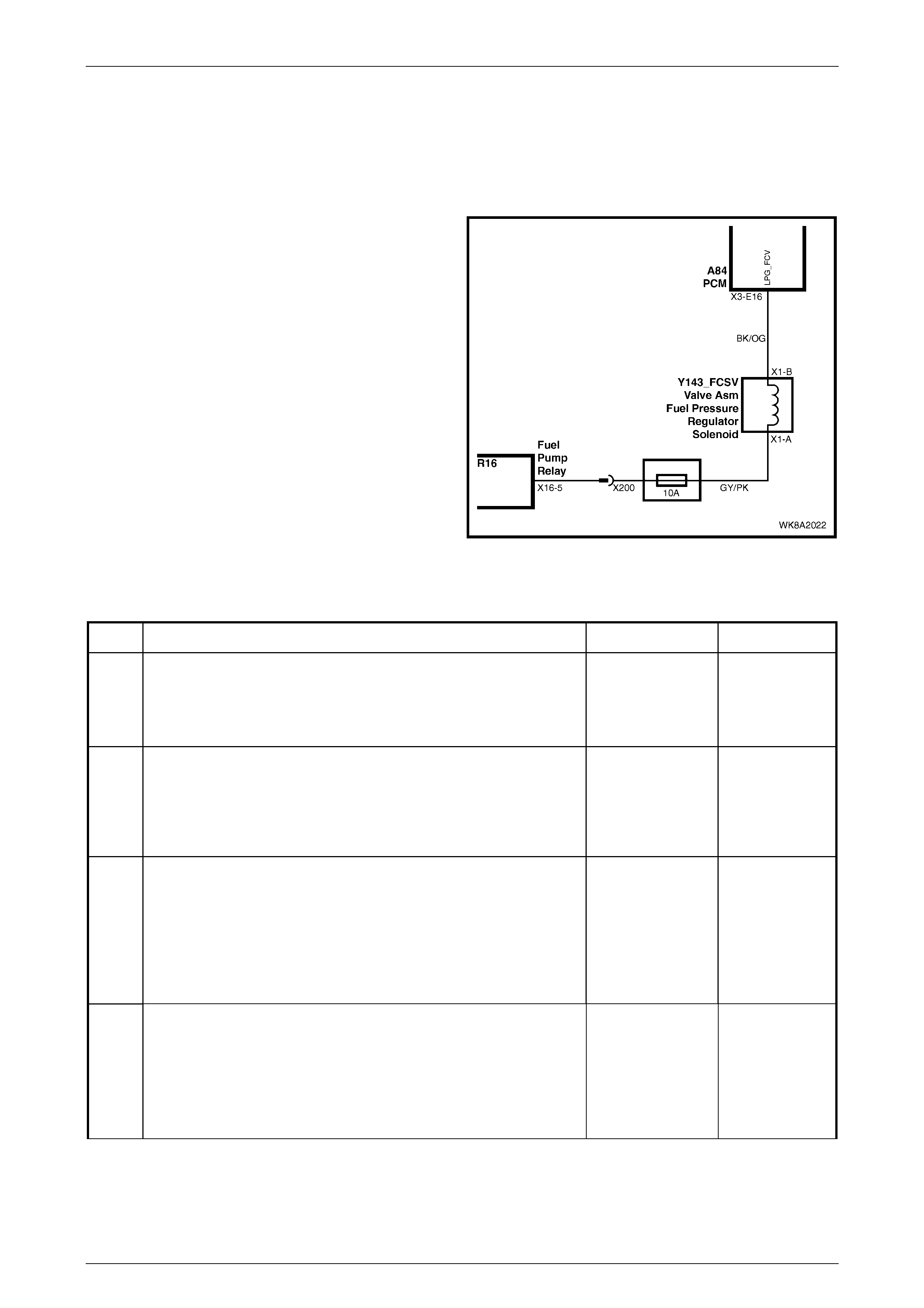
3.10 Fuel Control Valve Does Not Operate
Test Description
The numbers below refer to step numbers in the following diagnostic chart.
1 The LPG Vehicle Preliminary Diagnosis Check must
be the first step when diagnosing any LPG system
problem.
2 This test confirms if the fuel control valve (FCV) is
operating corr ectly .
3 This test confirms the continuity of the FCV circuit.
4 This test confirms that the PCM is pulsing the FCV
circuit to earth.
5 This test confirms that voltage is being applied to the
FCV.
6 This test confirms that the circuit from the PCM to the
FCV is not open or shorted to battery voltage.
7 This test confirms that the circuit from the PCM to the
FCV is not shorted to earth.
8 This test confirms the retention of the PCM terminals.
If the terminal retention is OK, the PCM should be
replaced.
Figure 8A2 – 18
Test Procedure
Step Action Yes No
1 1. Has the LPG Vehicle Preliminary Diagnosis Check been
performed? Go to step 2. Perform the
LPG Vehicle
Preliminary
Diagnosis
Check.
2 1 Perform a fuel control valve test, refer to Section 8A2, 3.20
Fuel Control Valve in the MY 2003 VY and V2 Series Service
Information.
2 Is the fuel control valve operating correctly?
Fuel control valve
operation is
intermittent.
Check retention of
all FCV circuit
terminals.
Go to Step 3.
3 1 Ignition OFF, disconnect PCM Connector A84_X3 terminal
E16.
2 Ignition ON.
3 Measure the voltage between the PCM connector A84_X3
terminal E16 and earth.
4 Is battery voltage present?
Turn the ignition
off and reconnect
the PCM
Connector A84
Go to Step 5.
Reconnect
PCM Connector
A84_X3
terminal E16
Go to Step 4.
4 1 Ignition ON, LPG selected.
2 Measure the voltage at the PCM connector A84_X3 terminal
E16 (Black/Orange wire) and earth.
3 Turn the ignition from off to on. Is there at least nine volts
present for three seconds when the ignition is first turned on or
when the engine is cranking?
Go to step 8. Go to Step 5.

LPG System Page 8A2–40
Page 8A2–40
Step Action Yes No
5 1 Ignition off.
2 Disconnect the FCV connector.
3 Ignition on.
4 Measure the voltage at the FCV connector circuit (Grey/Pink
wire) and earth.
5 Is battery voltage present?
Go to step 6. Repair open in
circuit
(Grey/Pink wire)
between the
fuse and
connector.
6 1 Check for open or short to voltage in the circuit (Black/Orange
wire) between the FCV connector and the PCM.
2 Is circuit open or shorted to voltage?
Repair open or
short to voltage
circuit
(Black/Orange
wire). Verify
repair.
Go to Step 7.
7 1. Check for a short to earth in circuit (Black/Orange wire)
between the FCV connector and the PCM.
2. Is circuit (Black/Orange wire) shorted to earth?
Repair short to
earth in circuit
(Black/Orange
wire). Verify
repair.
Go to step 8.
8 1 Check the PCM connector terminal retention.
2 Is PCM terminal retention OK?
Replace PCM.
Recheck starting
on LPG.
Repair PCM
terminals.
When all diagnosis and repairs are complete, verify correct operation.

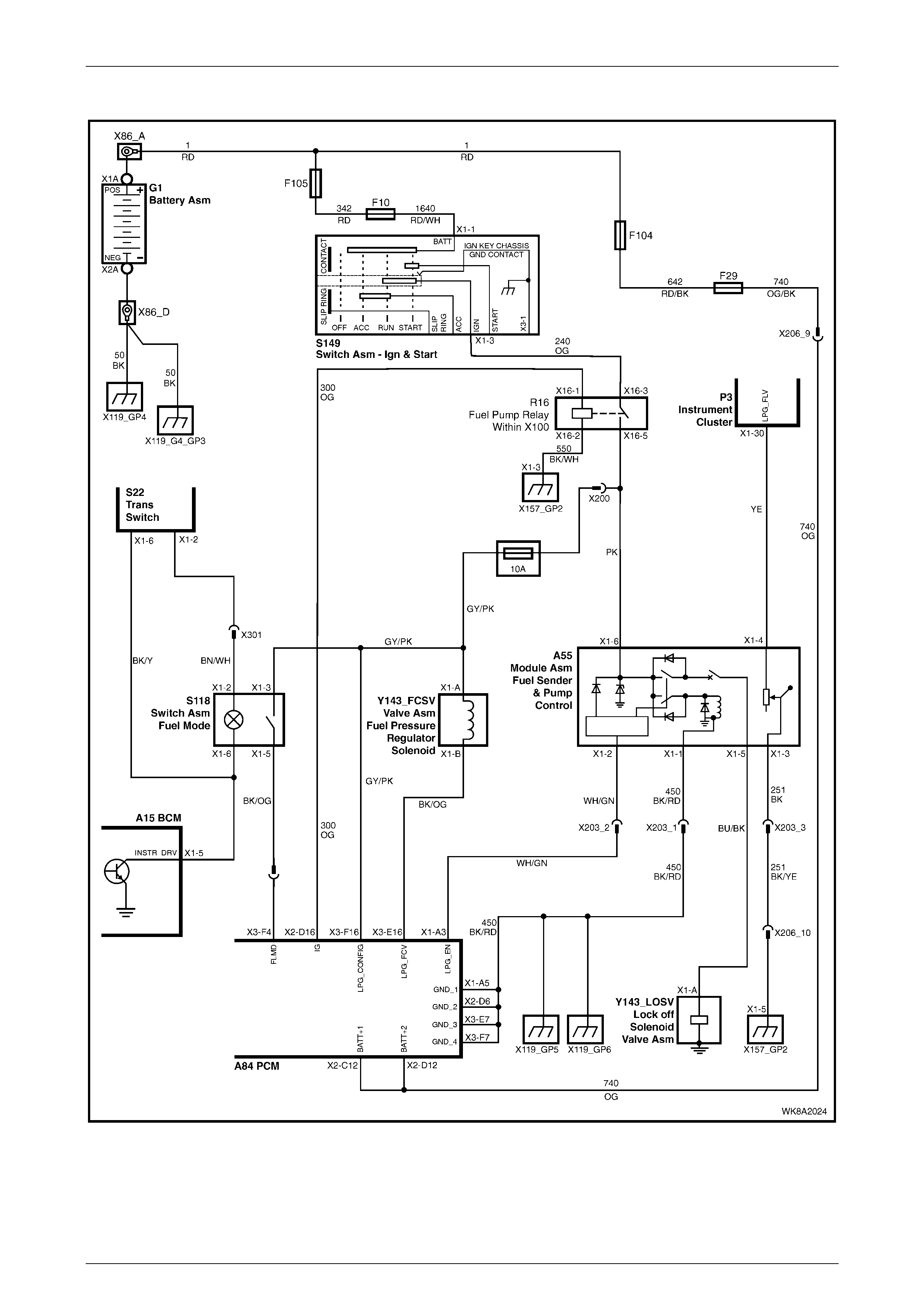
LPG System Page 8A2–42
Page 8A2–42
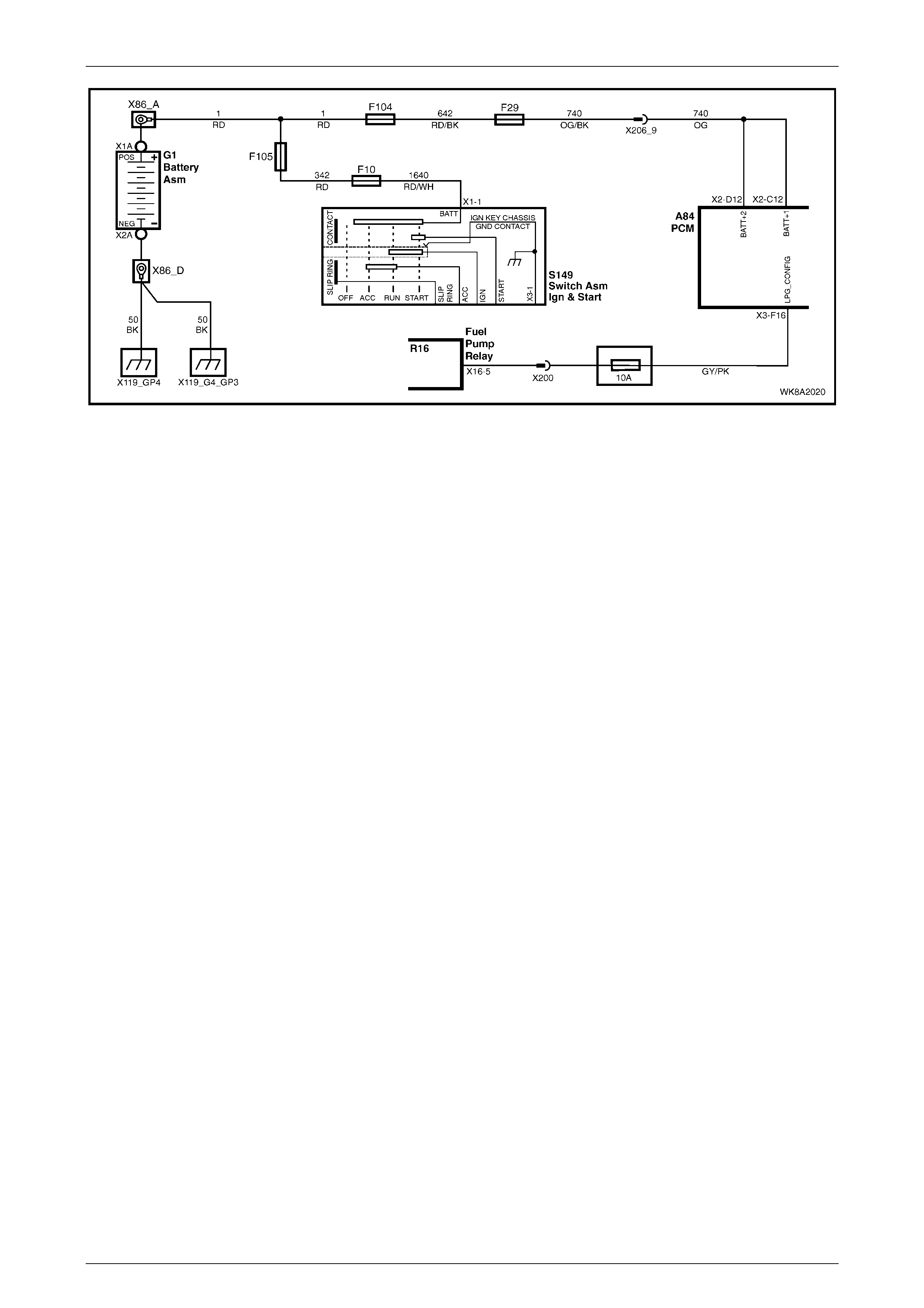
Wiring Schematics
Figure 8A2 – 19
LPG System Page 8A2–43
Page 8A2–43
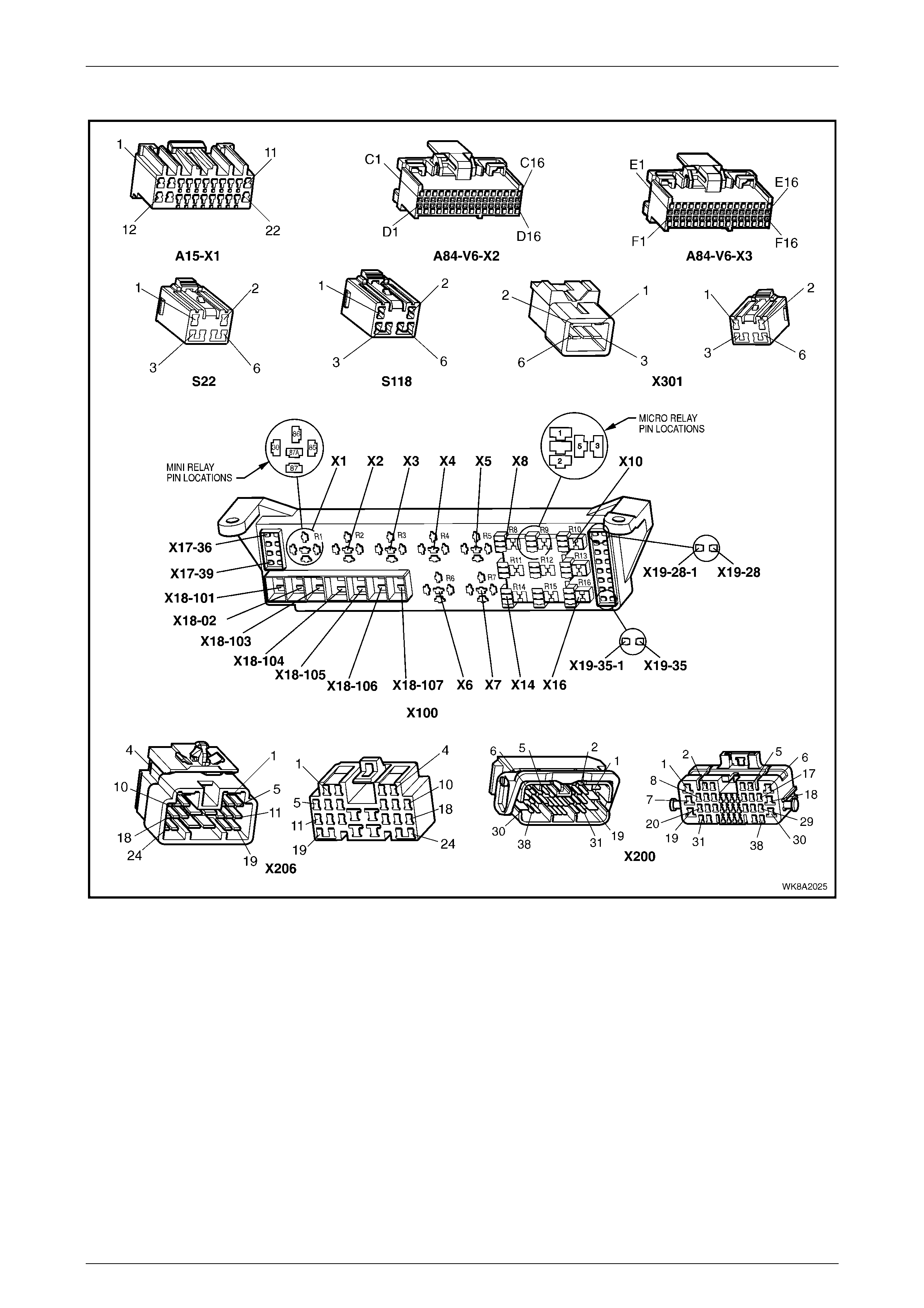
Connectors
Figure 8A2 – 20

LPG System Page 8A2–44
Page 8A2–44
5 Specifications
LPG tank capacity @ 80% ........................................................................... 74 litres ± 2 litres
Converter primary pressure ..................................................................1 - 1.5 psi (7 - 10 kPa)
Converter secondary pressure ...............................................................Negative 24 - 38 mm
Water column (W.C.)
Contents gauge sender unit resistance:
Empty.........................................................................................................................40 Ohms
Full...........................................................................................................................255 Ohms
Fuel Control Valve (FCV) resistance .....................................................19 - 21 ohms @ 20°C
LPG lock-off coil resistance ...................................................................17 - 27 ohms @ 20°C
LPG lock-off pressure rating .....................................................................................1200 kPa
Spark plug gap.............................................................................................................. 1.4mm

LPG System Page 8A2–45
Page 8A2–45
6 Tech 2 Scan Tool : Engine Data
The Tech 2 scan tool engine data tables listed for the MY 2003 VY Series vehicles in Section 8A2, 6.11 of the MY 2003
VY and V2 Series Service Information may be used for comparison when diagnosing faults on MY 2004 WK Series
vehicles operating on LPG.
After completing:
• The LPG Vehicle Preliminary Diagnosis, refer to 3.3 LPG Vehicle Preliminary Diagnosis.
• On-Board Diagnostic System Check, refer to Section 6C1 in the MY 2004 VY and V2 Series Service Information.
• Finding the on-board diagnostics are functioning properly.
• No diagnostic DTCs are displayed.
For further information, refer to Section 8A2, in the MY 2003 VY and V2 Series Service Information.

LPG System Page 8A2–46
Page 8A2–46
7 Torque Wrench Specifications
Rear Service Line to Intermediate
Service Line Connector..............................................................12.0 – 18.0 Nm
Front Service Line to Lock-off and Intermediate
Service Line Connector..............................................................12.0 – 18.0 Nm
Rear Service Line to Intermediate
Service Line Connector..............................................................12.0 – 18.0 Nm
Front Service Line to Intermediate
Service Line Connector..............................................................12.0 – 18.0 Nm
Front Service Line Retaining Clip ..............................................12.0 – 15.0 Nm