
Exhaust System Page 8B–1
Page 8B–1
Section 8B
EXHAUST SYSTEM
IMPORTANT
Before performing any service operation or other procedure described in this Section, refer to Section 00
Warnings, Cautions and Notes for correct workshop practices w ith regard to safety and/or property damage.
1 General Description............................................................................................................................... 3
1.1 Emission Reductions.............................................................................................................................................3
Catalytic Converter Close Coupling.....................................................................................................................3
Euro 2 Emissions Standards.................................................................................................................................3
1.2 Exhaust System Configurations...........................................................................................................................4
V6 Engine Exhaust System ...................................................................................................................................4
GEN III V8 Engine Exhaust System.......................................................................................................................5
Standard.............................................................................................................................................................5
Performance.......................................................................................................................................................6
2 Service Operations - V6......................................................................................................................... 7
2.1 Service Notes .........................................................................................................................................................7
Catalytic Converter.................................................................................................................................................7
Oxygen Sensors.....................................................................................................................................................7
2.2 Exhaust System......................................................................................................................................................8
Complete Exhaust System Assembly...................................................................................................................9
Remove..............................................................................................................................................................9
Reinstall............................................................................................................................................................10
2.3 Rear Exhaust Assembly.......................................................................................................................................11
Remove .................................................................................................................................................................11
Reinstall................................................................................................................................................................11
2.4 Intermediate Exhaust Single Pipe and Muffler Assembly ................................................................................12
Remove .................................................................................................................................................................12
Reinstall................................................................................................................................................................12
2.5 Intermediate Exhaust Y-Pipe Assembly.............................................................................................................13
Remove .................................................................................................................................................................13
Reinstall................................................................................................................................................................14
2.6 Front Exhaust Assembly.....................................................................................................................................15
Remove .................................................................................................................................................................15
Reinstall................................................................................................................................................................16
2.7 Tightening Sequence...........................................................................................................................................17
3 Service Operations – GEN III V8......................................................................................................... 19
3.1 Service Notes .......................................................................................................................................................19
Catalytic Converter...............................................................................................................................................19
Oxygen Sensors...................................................................................................................................................19
3.2 Exhaust System....................................................................................................................................................20
3.3 Complete Exhaust System Assembly.................................................................................................................21
Remove .................................................................................................................................................................21
Reinstall................................................................................................................................................................22
3.4 Rear Exhaust Assembly.......................................................................................................................................23
Remove .................................................................................................................................................................23
Reinstall................................................................................................................................................................24
Techline

Exhaust System Page 8B–2
Page 8B–2
3.5 Intermediate Exhaust Assembly.........................................................................................................................25
Remove .................................................................................................................................................................25
Reinstall................................................................................................................................................................25
3.6 Front Exhaust Assembly.....................................................................................................................................26
Remove .................................................................................................................................................................26
Reinstall................................................................................................................................................................27
3.7 Tightening Sequence...........................................................................................................................................28
4 Service Operations – Exhaust System Heat Shields........................................................................ 30
4.1 Heat Shields ..........................................................................................................................................................30
Rear Muffler Underbody Mounted Heat Shield..................................................................................................32
Remove............................................................................................................................................................32
Reinstall............................................................................................................................................................32
Intermediate Muffler Underbody Mounted Heat Shield.....................................................................................33
Remove............................................................................................................................................................33
Reinstall............................................................................................................................................................33
Front Exhaust Assembly Underbody Mounted Heat Shields...........................................................................34
Remove............................................................................................................................................................34
Reinstall............................................................................................................................................................34
Front Exhaust Assembly On-pipe Heat Shields – Pre Catalytic Converter.....................................................35
Remove............................................................................................................................................................35
Reinstall............................................................................................................................................................35
Front Exhaust Assembly On-pipe Heat Shields - Post Catalytic Converter....................................................35
Remove............................................................................................................................................................35
Reinstall............................................................................................................................................................36
Butyl Patch Reflective Foil Heat Shields – V6 Supercharged Only..................................................................37
Remove............................................................................................................................................................37
Reinstall............................................................................................................................................................37
5 Exhaust System Clearances............................................................................................................... 38
5.1 V6 Exhaust Systems Clearances........................................................................................................................38
5.2 GEN III V8 Exhaust System Clearances .............................................................................................................42
6 Exhaust System Diagnosis................................................................................................................. 47
7 Specifications....................................................................................................................................... 48
Type.......................................................................................................................................................................48
Material..................................................................................................................................................................48
Catalytic Converter...............................................................................................................................................48
8 Torque Wrench Specifications........................................................................................................... 49
9 Special Tools........................................................................................................................................ 50

Exhaust System Page 8B–3
Page 8B–3
1 General Description
Information contained within this section describes the general exhaust system configurations for MY 2004 WK Series
vehicles. The exhaust system fitted to a particular vehicle will depend on engine type and model specifications. With the
following exceptions, MY 2004 WK Exhaust System information carries over from MY 2003 VY and V2 Series vehicles.
V6 exhaust system:
• Complete system update except for rear exhaust assembly, which carries over from MY 2003 VY and V2 Series.
The new system incorporates two close-coupled catalytic converters, on-pipe heat shielding and reconfigured front
to intermediate exhaust assemblies.
V6 Supercharged exhaust system:
• Similar to VY V6 Supercharged, except for the use of shortened butyl patch reflective foil heat shields and revised
catalytic converter volume specifications. Refer to V6 Supercharged exhaust system information contained within
the MY 2003 VY and V2 Series Service Information.
GEN III V8 exhaust system:
• Revised front exhaust assemblies incorporating close-coupled catalytic converters, revised under body heat shield
configuration and new on-pipe heat shields.
• GEN III V8 vehicles produced before 11 September 2003 are fitted with long on-pipe heat sheilds to the front
exhaust assembly. Vehicles produced from this date onwards are fitted with short on-pipe heat shields to the front
exhaust assembly.
NOTE
All illustrations in this Section represent a
right-hand drive vehicle. For left-hand drive
vehicles, any procedure or item that is not a
direct mirror of a right-hand drive vehicle in
left-hand drive configuration, will be highlighted
and a procedure or illustration produced to
accommodate the difference.
For information not contained within this Section, refer to Section 8B Exhaust System, in the MY 2003 VY and V2 Series
Service Information.
1.1 Emission Reductions
Through developments in various vehicle emissions reduction systems, significant reductions in emissions have been
achieved on WK vehicles with V6 and GEN III V8 engines. The developments have been primarily concerned with
refinements in engine calibration and the optimisation of exhaust system catalytic converter configurations. For WK
Series exhaust systems, the major modifications made to reduce emissions from previous Series vehicles includes the
incorporation of two catalytic converters on V6 vehicles and a close-coupled catalytic converter configuration
incorporated across both V6 (non-supercharged) and GEN III V8 vehicles.
Catalytic Converter Close Coupling
As optimum catalytic converter performance is reached above 500oC, a close coupling of the catalytic converter with the
exhaust manifold ensures that upon engine startup, the engine exhaust gasses are able to heat the catalytic converter
to optimum temperatures in as short a time as possible. This period of catalytic converter warm up is often referred to as
catalytic converter ‘light up’.
Euro 2 Emissi ons St andar ds
WK vehicles with V6 (non-supercharged) and GEN III V8 engines now meet Euro 2 emissions standards. The Euro 2
emissions standard is a European standard which aims at setting vehicle emissions targets to encourage vehicle
manufacturers to reduce harmful vehicle emissions such as Carbon Monoxide (CO), Hydrocarbons (HC) and the various
oxides of Nitrogen (NOx).
For further information on catalytic converter construction and operation, refer to Section 8B, 1.2 Exhaust Catalytic
Converter, in the MY 2003 VY and V2 Series Service Information.
Exhaust System Page 8B–4
Page 8B–4
1.2 Exhaust System Configurations
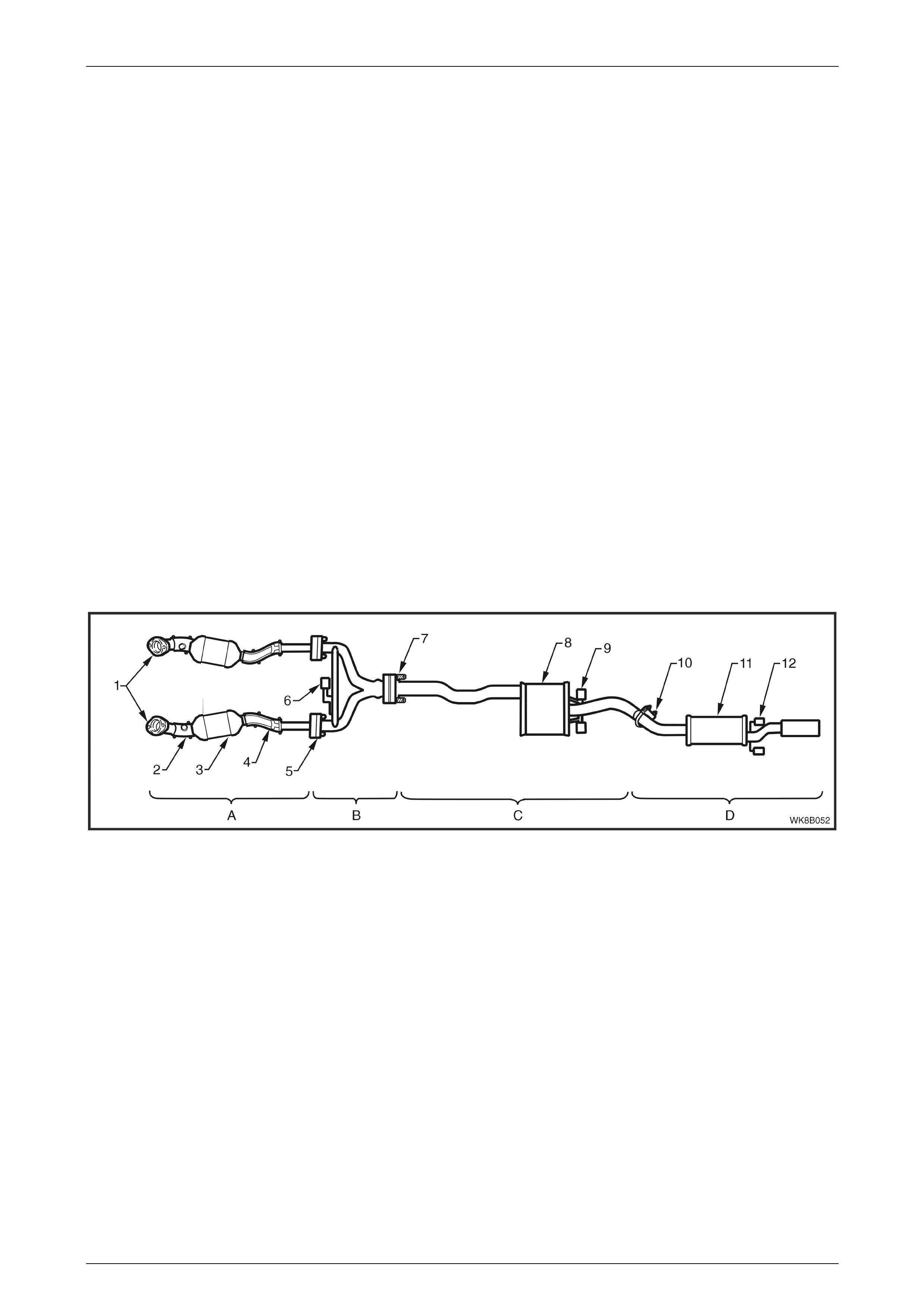
V6 Engine Exhaust System
Refer to Figure 8B – 1 for the following.
The V6 engine exhaust manifolds are connected to a pair of stainless steel front pipes by flanged joints (1). Each front
pipe runs into a close-coupled three-way catalytic converter (3) and then continues from the rear of the converter to join
up with the intermediate Y-pipe exhaust assembly. These pipes are joined by gasketed flange joints (5). The
intermediate Y-pipe assembly merges into a single pipe and joins onto the intermediate single pipe and muffler
assembly with a flanged swivel joint (7). An internal sealing ring is fitted within the joint. The flanged swivel joint is held
together with a pair of stepped fastening bolts and coil springs. Combined, the Y-pipe and single pipe and muffler
assemblies (items B and C)are identified as the intermediate exhaust assembly.
The intermediate single pipe runs on into the intermediate muffler (8) and extends from the rear of the muffler to join up
with the rear exhaust pipe and muffler assembly. The intermediate to rear pipes are joined with a slip joint and U-bolt
clamp (10).
The front of the exhaust assembly is supported through a rubber support (6) attached to a hanger connected to the
transmission extension housing and to a cross brace and peg assembly welded across the intermediate Y-pipe exhaust
assembly. The intermediate single pipe and muffler exhaust assembly is supported by two support rubbers (9) that are
attached to hangers welded to the vehicle underbody and to pegs welded to the rear of the intermediate muffler. The
rear exhaust assembly is supported by two support rubbers (12) that are attached to hangers welded to the vehicle
underbody and to pegs welded to the tailpipe just downstream of the rear muffler (11).
The support rubbers are a common part for all locations and are secured by retainer clips at the intermediate and rear
body hangars. Flanged pegs are used at other locations.
Pre catalytic converter on-pipe heat shields (2) and post catalytic converter on-pipe heat shields (4) are used along the
front exhaust pipe assemblies. Metal plate heat shields attached to the underbody are used above the intermediate and
rear mufflers. Foil plate heat shields are attached to the underbody just to the rear of each catalytic converter.
Figure 8B – 1
Legend
A Front Exhaust Assem bli es
B Intermediate Y-Pipe Exhaust
Assembly
C Intermediate Si ngl e Pipe and
Muffler Assembly
D Rear Exhaust Assembly
1 Manifold to Front P i pe Fl ange
2 Pre Catalyt i c Converter Heat S hi el ds
and Oxygen Sensor Mounting Boss
3 Catalytic Converter
4 Post Catalytic Converter Heat Shiel ds
5 Front Pipe to Y-Pipe Flange Joi nt
6 Front Exhaust Brace and Support
Rubber
7 Swivel Joint Flange
8 Intermediate Muffler
9 Intermediate Muff l er Support Rubbers
10 Intermediate to Rear Pipe Slip Joint and
U-clamp
11 Rear Muffler
12 Rear Muffler Support Rubbers
Exhaust System Page 8B–5
Page 8B–5
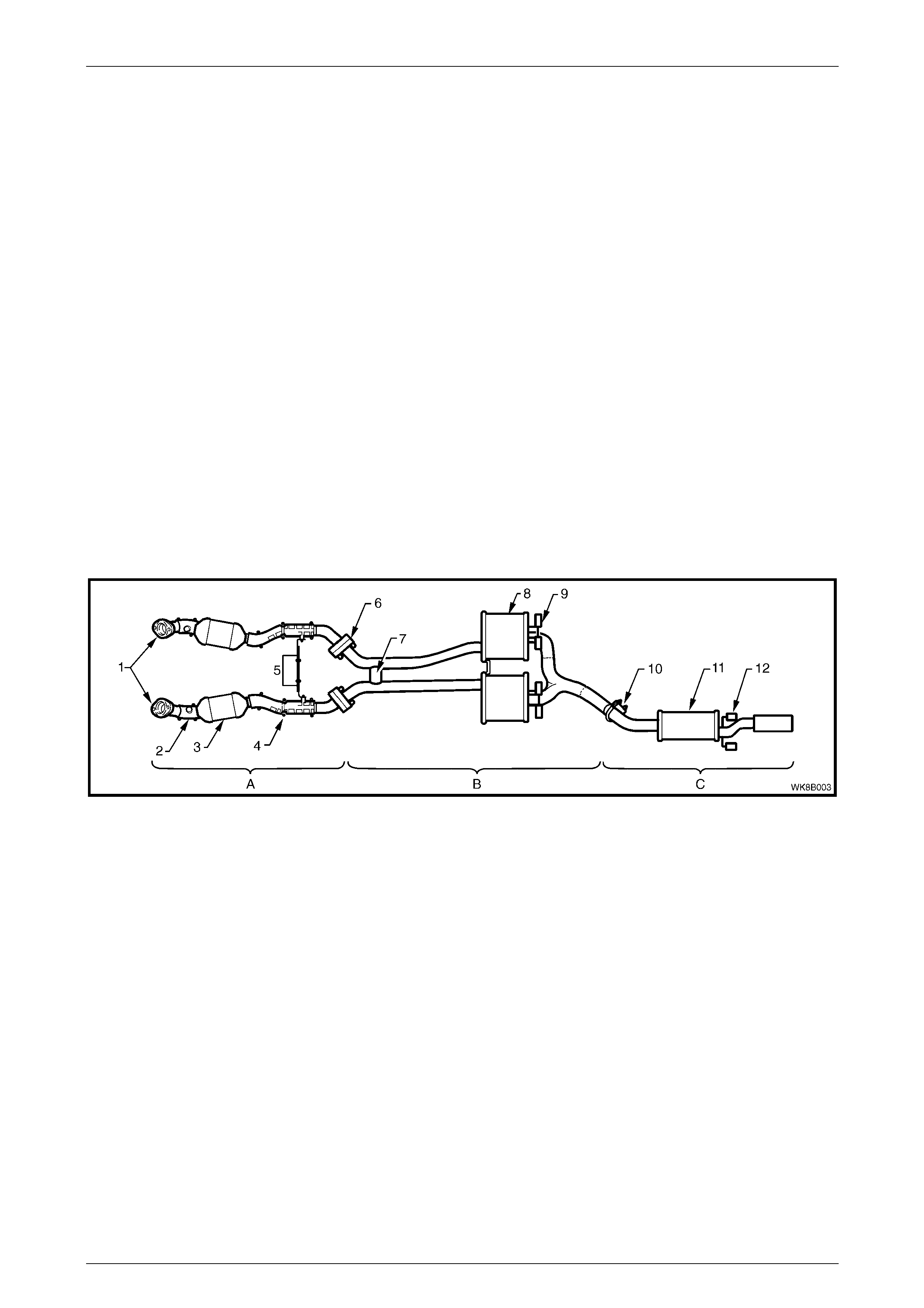
GEN III V8 Engine Exhaust System
Two exhaust system configurations, Standard and Performance, are available for vehicles fitted with the GEN III V8
engine. The type installed will depend on the particular vehicle’s specifications. Details of both of these systems are
included.
Standard
Refer to Figure 8B – 2 for the following.
The GEN III V8 engine exhaust manifolds are connected to a pair of stainless steel front pipes by flanged joints (1). A
dual exhaust system is retained past the twin intermediate mufflers (8). The pipes then converge into a single pipe that
is joined to the rear exhaust assembly with a slip joint and U-bolt clamp (10).
A catalytic converter (3) is welded to each front exhaust pipe, with a flanged, gasketed joint (6) connecting each
converter to the twin, intermediate exhaust pipes.
The front of the exhaust assembly is supported through a cross brace and transmission mount (5), which bridges
between each of the front exhaust pipes and is bolted onto the transmission extension housing. The two intermediate
exhaust pipes are stiffened by a welded bridging piece, located before the twin intermediate mufflers. The bridging piece
also functions as an exhaust balance pipe (7). The intermediate exhaust assembly is supported by two pairs of support
rubbers (9) attached to hangers welded to the vehicle underbody and to pegs welded to the rear of the intermediate
mufflers (8). The rear exhaust assembly is supported by two support rubbers (12) attached to hangers welded to the
vehicle underbody and to pegs welded to the rear tail pipe.
The support rubbers are a common part for all locations and are secured by retainer clips at both the intermediate and
rear body hangers. Flanged pegs are used at other locations.
Pre catalytic converter on-pipe heat shields (2) and post catalytic converter on-pipe heat shields (4) are used along each
of the front exhaust pipes. Metal plate heat shields attached to the underbody are used above the intermediate and rear
mufflers. Foil plate heat shields are attached to the underbody, just to the rear of each catalytic converter.
Figure 8B – 2
Legend
A Front Exhaust Assem bli es
B Intermediate Exhaust A ssem bl y
C Rear Exhaust Assembly
1 Manifold to Front P i pe Fl ange
2 Pre Catalyt i c Converter Heat S hi el ds
and Oxygen Sensor Mounting Boss
3 Catalytic Converter
4 Post Catalytic Converter Heat Shiel ds
5 Cross B rac e and Transmi ssion Mount
6 Front Pipe t o I ntermediat e Fl ange Joint
7 Exhaust Balance Pipe
8 Intermediate Muffler
9 Intermediate Muff l er Support Rubbers
10 Intermediate to Rear Pipe Slip Joint and
U-clamp
11 Rear Muffler
12 Rear Muffler Support Rubbers
Exhaust System Page 8B–6
Page 8B–6
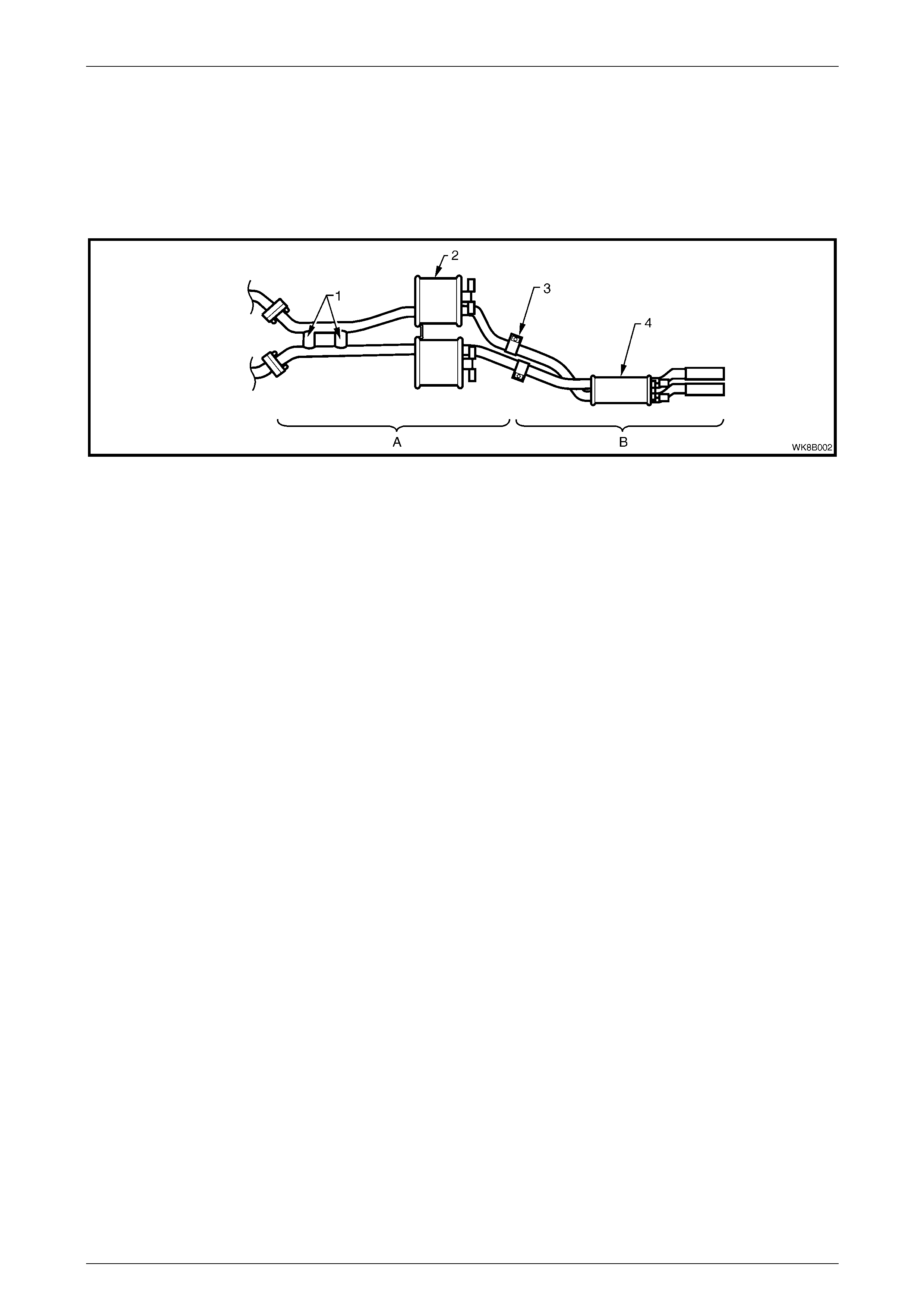
Performance
Refer to Figure 8B – 3 for the following.
The front exhaust assemblies of the Performance exhaust system are identical to the Standard front exhaust
assemblies. The intermediate exhaust assembly incorporates two exhaust balance pipes (1) welded at points before the
twin intermediate mufflers (2). The pipes running from the intermediate mufflers are joined to the rear exhaust pipes with
individual slip joints and ring clamps (3). The rear exhaust pipes join to a single rear muffler (4), which features dual tail
exhaust pipes.
Figure 8B – 3
Legend
A Intermediate Exhaust S ystem
B Rear Exhaust Assembly 1 E xhaust bal ance pipes
2 Intermediate mufflers 3 Intermediate to Rear Pipe Slip Joints
and Ring Clam ps
4 Rear Muffler
Exhaust System Page 8B–7
Page 8B–7
2 Service Operations - V6
2.1 Service Notes
When installing any exhaust system component, care must be taken to install each component in the correct
relationship to the other. Ensure that correct assembly, installation, tightening sequence, tightening torque and
clearances for the system involved are observed. When exhaust system service work is required, refer to the various
illustrations and instructions provided in this section.
The incorrect assembly of exhaust system
components can frequently be the cause of
rattles and ‘booms' due to incorrect
alignment or clearance of body or suspension
parts. Ensure that the correct tightening
sequence is observed upon installation of
exhaust system components.
NOTE
Service operations on exhaust system
components must be carried out with all parts at
ambient temperatures to ensure correct
clearances are maintained.
Catalytic Converter
Catalytic converters are serviced as part of the left or right front exhaust pipe assemblies only.
NOTE
If removing or replacing the catalytic converter as
part of a complete front pipe assembly, always
check the flange gaskets for damage and replace
if necessary.
Oxygen Sensors
When removing the front exhaust pipes, it is necessary to
disconnect the wiring harness connectors from each of the
two oxygen sensors (1).
For oxygen sensor replacement, refer to Section 6C1, 6.1
Oxygen Sensor.
Figure 8B – 4
Exhaust System Page 8B–8
Page 8B–8
2.2 Exhaust System
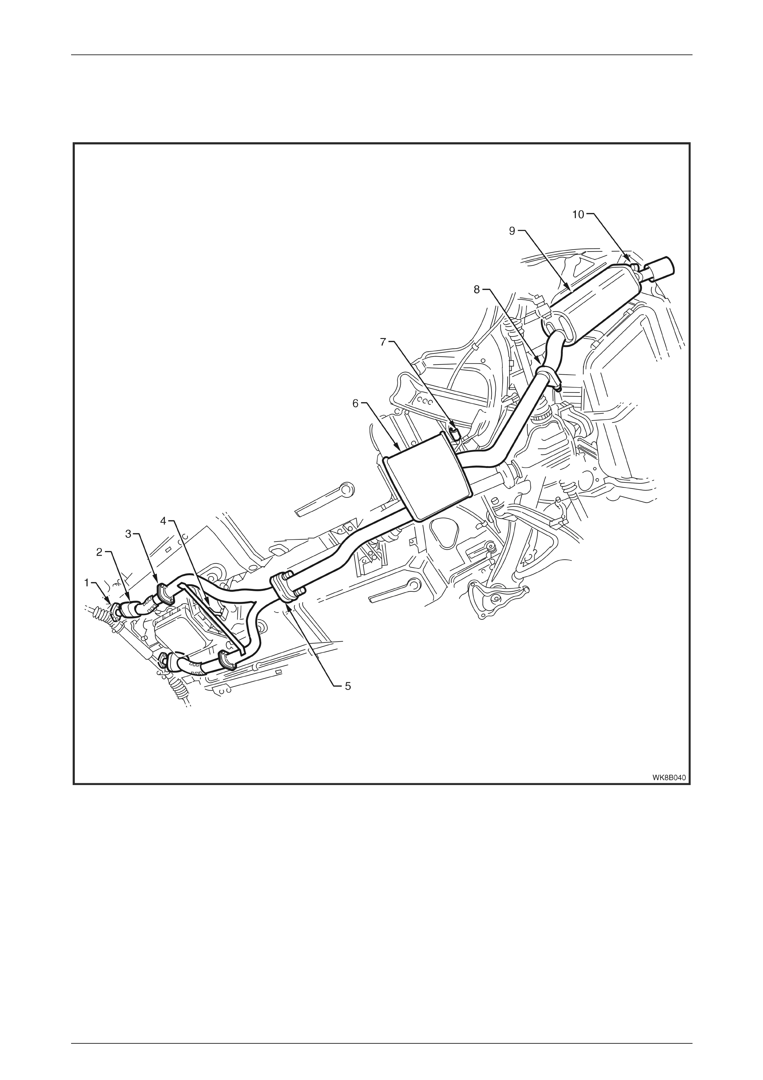
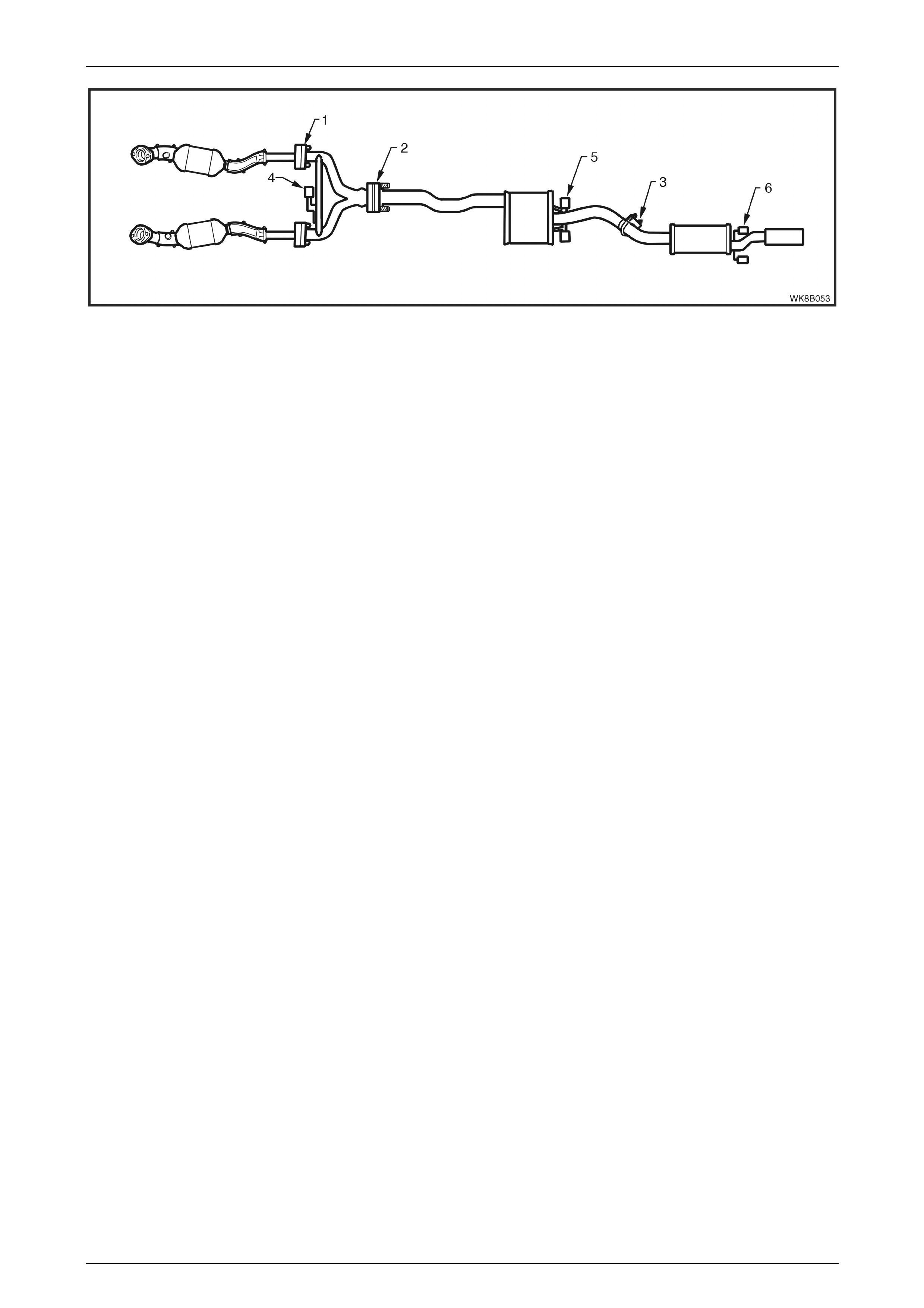
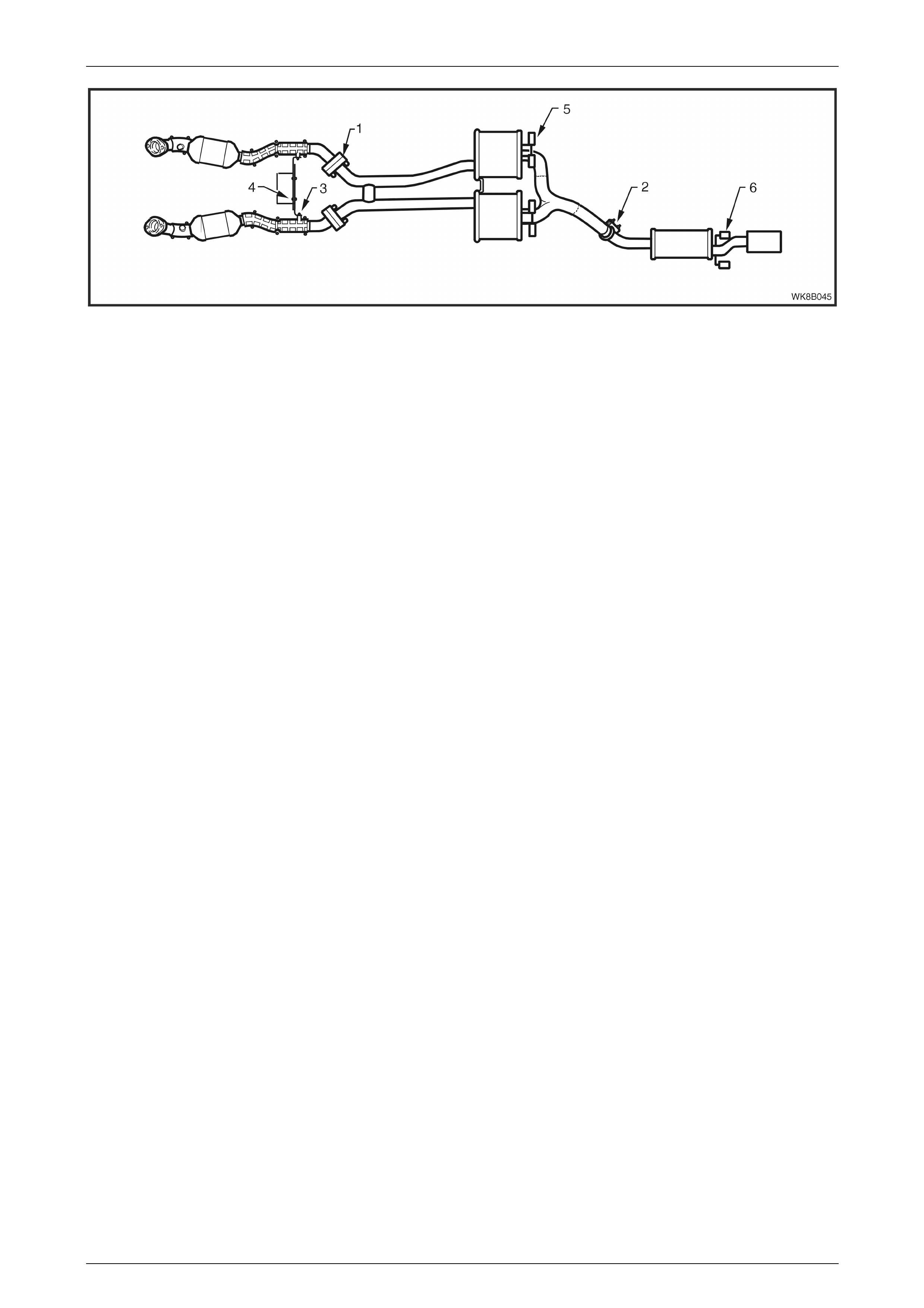
Figure 8B – 5 illustrates the exhaust system configuration used with the V6 engine.
Figure 8B – 5
Legend
1 Manifold to Front P i pe Fl ange
2 Catalytic Converter
3 Front pipe to I nt ermediate Y -Pipe Flange
4 Y-Pipe Brace and Rubber Support
5 Flange Swivel Joint
6 Intermediate Muffler
7 Intermediate Muff l er S upport Rubbers
8 Intermediate to Rear Pipe Slip Joint and U-cl amp
9 Rear Muffler
10 Rear Muffler Support Rubbers
Exhaust System Page 8B–9
Page 8B–9
Complete Exhaust System Assembly
Remove
1 Disconnect the wiring harness connectors from each
of the two oxygen sensors (1).
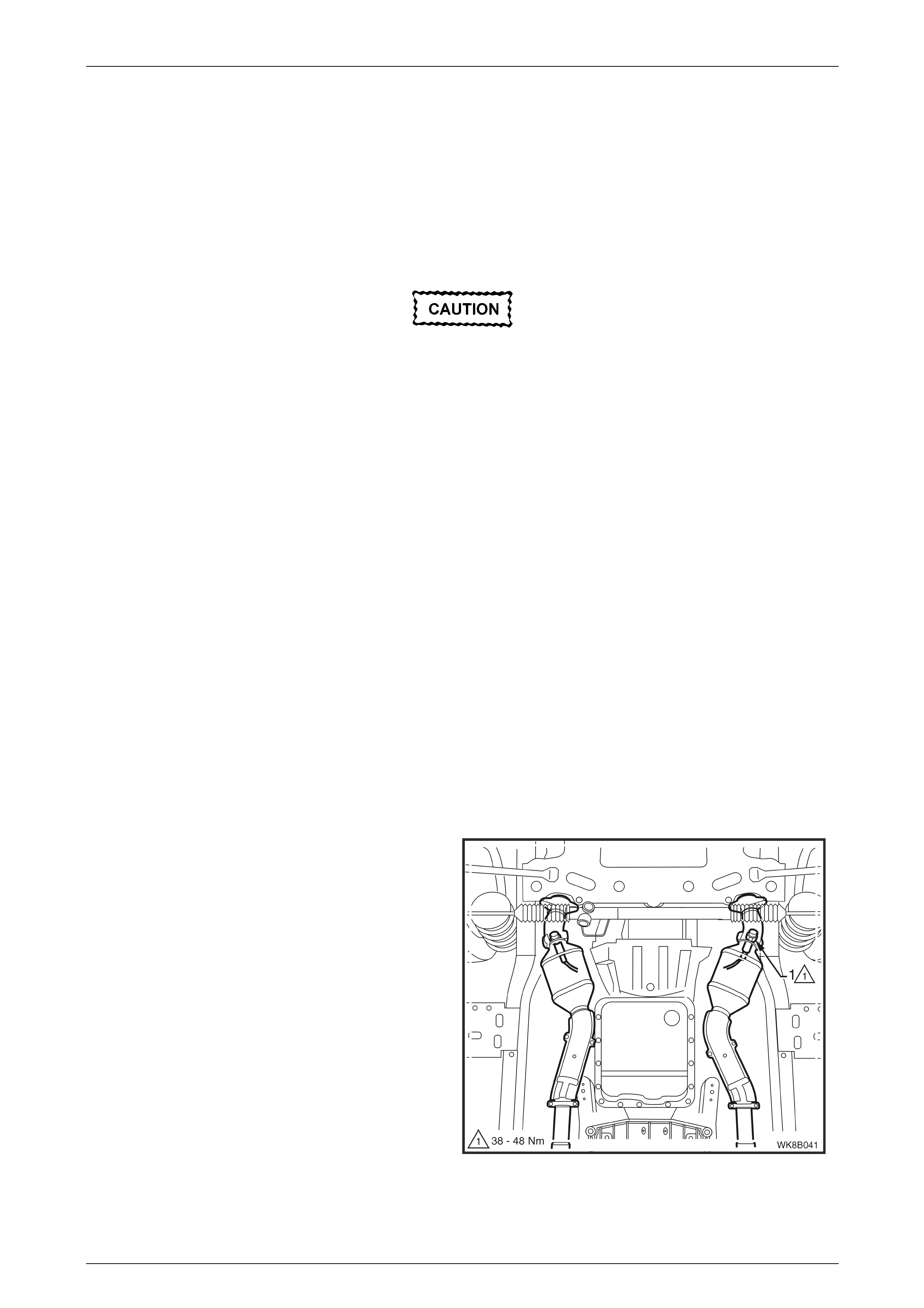
Figure 8B – 6
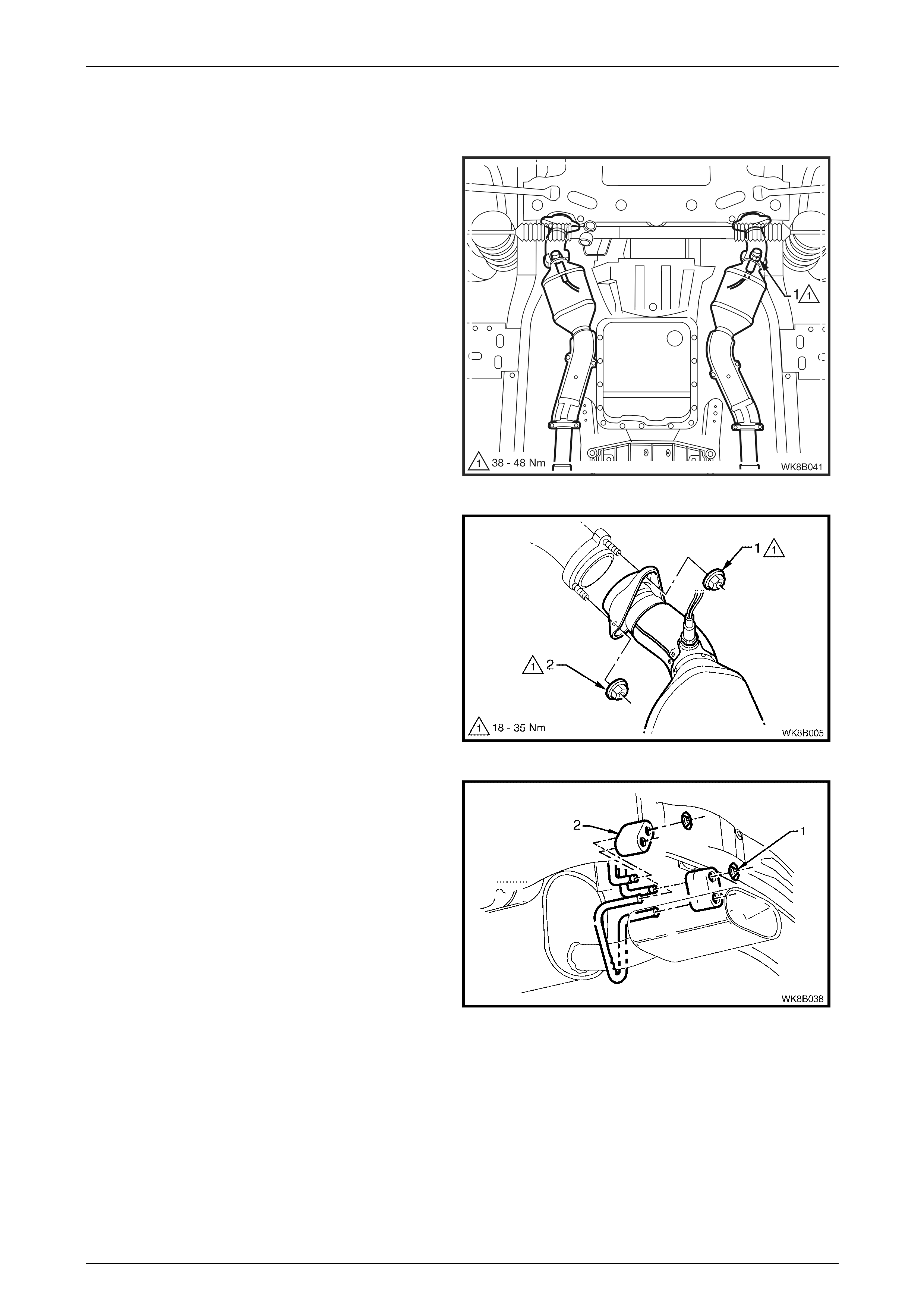
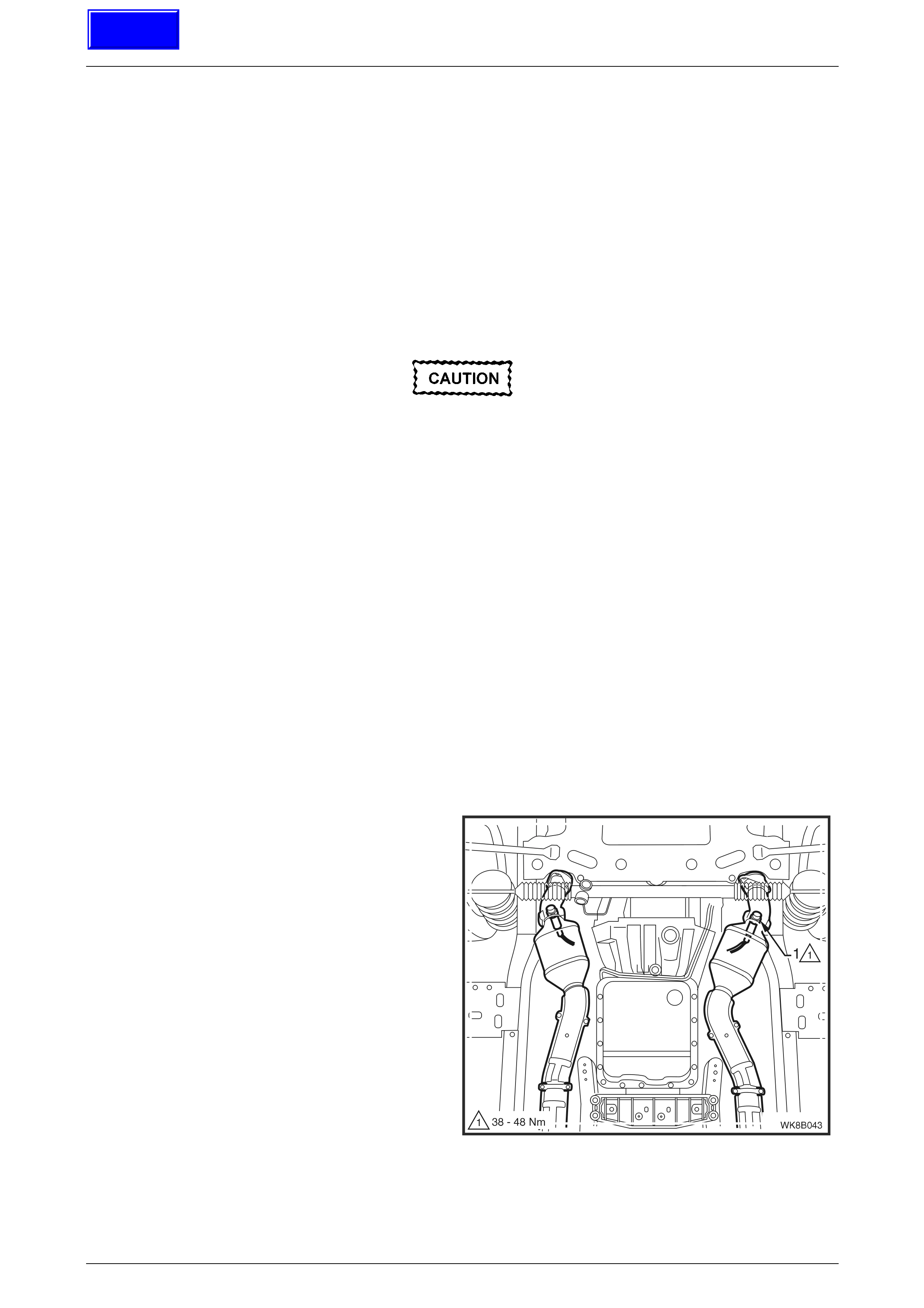
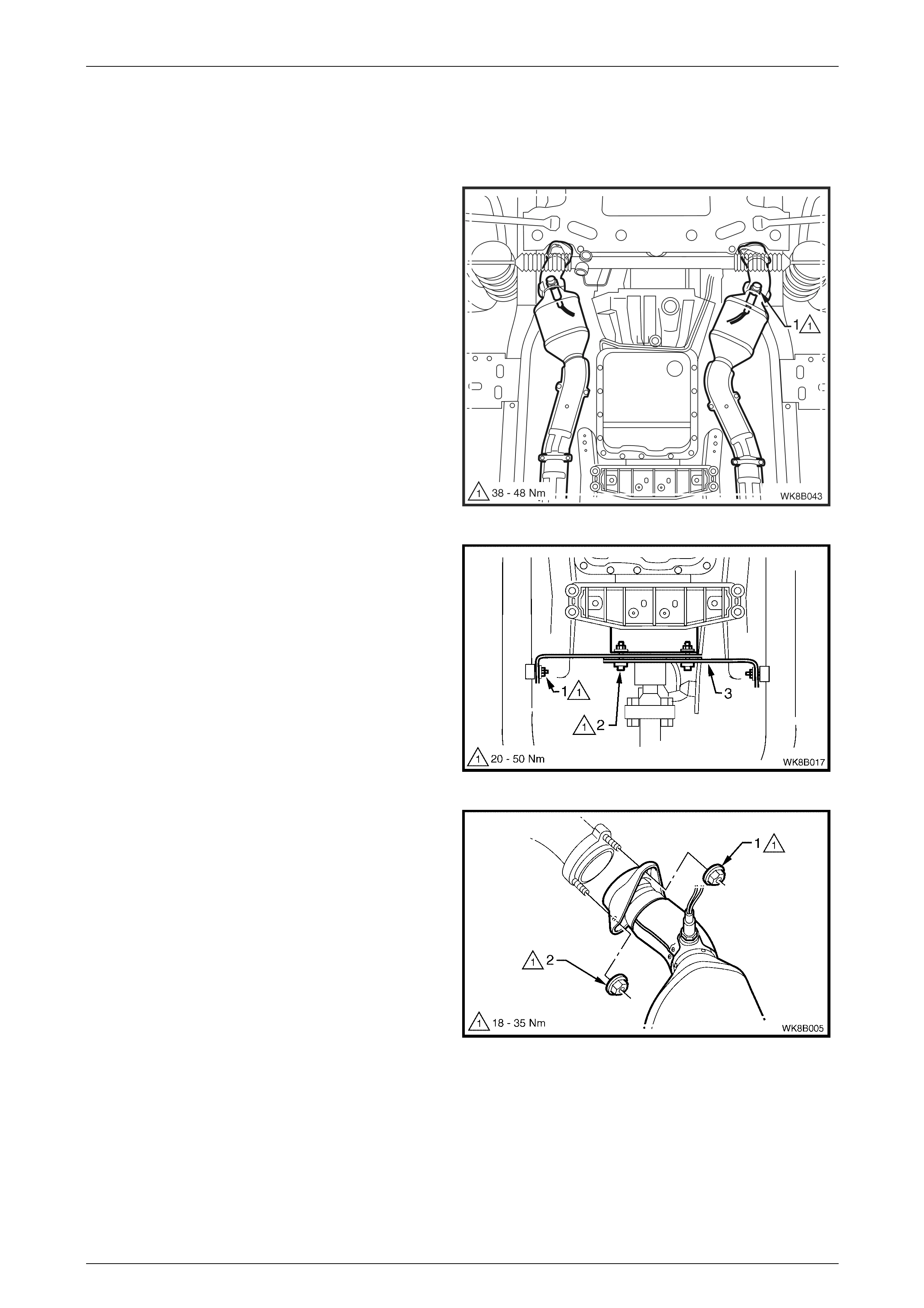
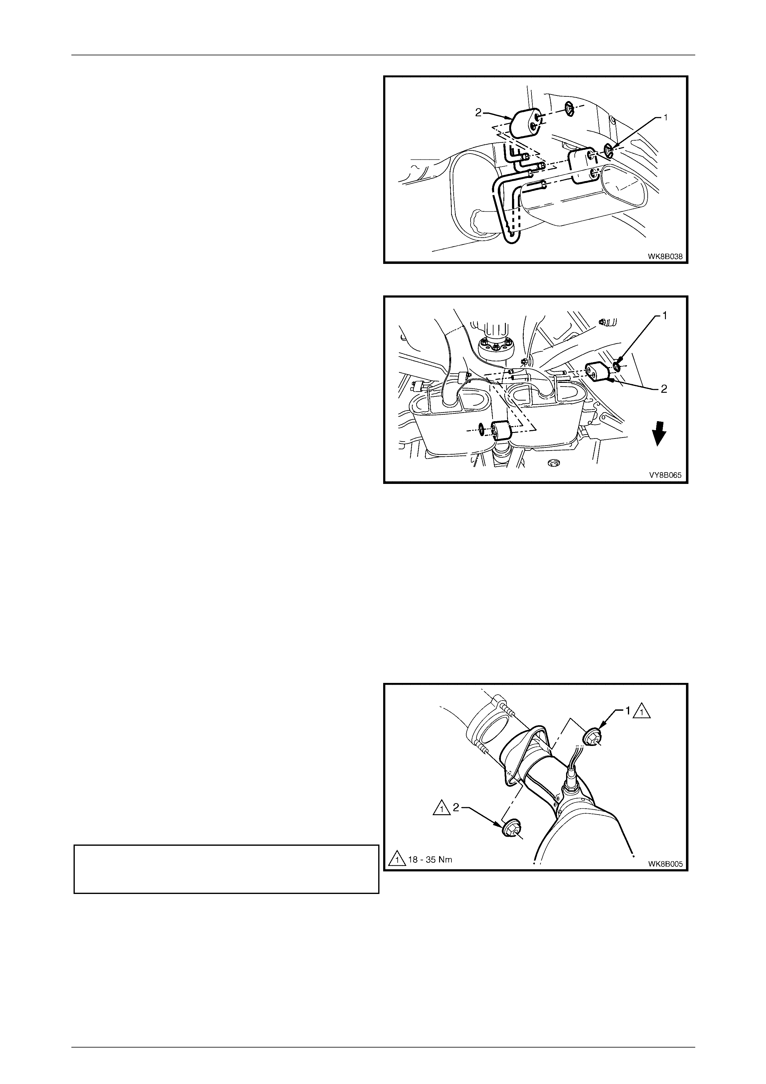
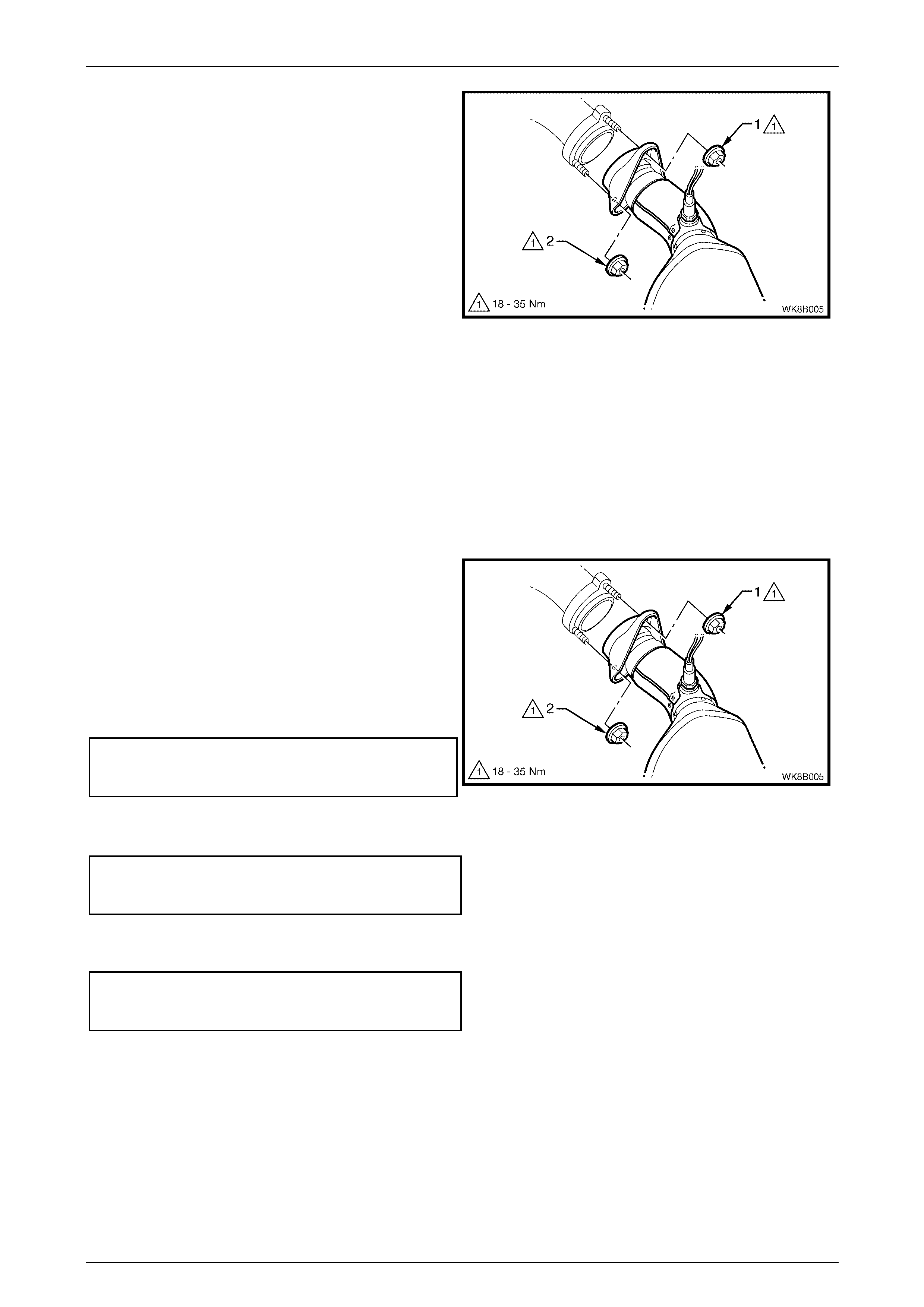
2 Support the exhaust system and remove the
upper (1) then lower (2) fastening nuts from the front
exhaust assembly to exhaust manifold flange studs
on both sides.
Figure 8B – 7
3 Disconnect the rear muffler from the support hangers
by removing the two retainer clips (1) and support
rubbers (2).
Figure 8B – 8
Exhaust System Page 8B–10
Page 8B–10
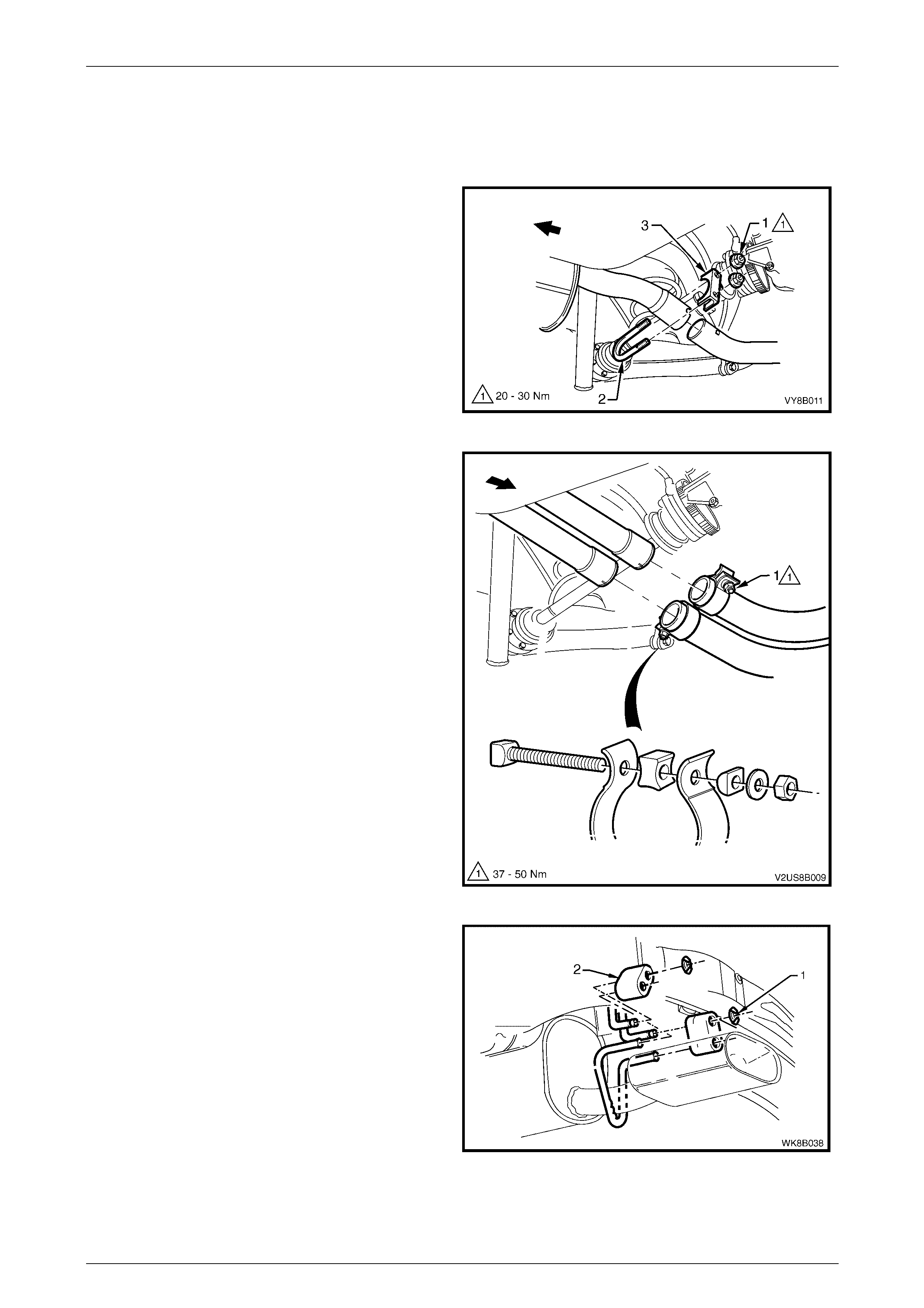
4 Support the exhaust system and disconnect the
intermediate muffler from the support hangers by
removing the two retainer clips (1) and the two
support rubbers (2).
Figure 8B – 9
5 Disconnect the front exhaust assembly by removing
the support rubber (1) from the peg welded to the
exhaust pipe brace.
6 Carefully lower and remove the exhaust assembly
from the vehicle, taking care not to damage the
exhaust gas oxygen sensors.
Figure 8B – 10
Reinstall
Installation of the complete exhaust system is the reverse of the removal procedure, noting the following points:
1 Support the exhaust system at all times.
2 Clean the threads of the manifold flange studs with a suitable cleaning solvent.
3 Hand tighten the upper fastening nut (1) to the stud
on both sides.
4 Hand tighten the lower fastening nut (2) to the stud
on both sides.
5 Tighten the upper then lower fastening nuts so that
approximately equal amounts of stud thread are
showing.
6 Tighten the upper then lower fastening nuts to the
specified torque.
Front exhaust assembly to exhaust
manifold flange stud fastening nut
torque specification..................................... 18 – 35 Nm
Figure 8B – 11
7 Ensure all support rubbers are under load.
8 Check the exhaust system for clearances, refer to 5.1 V6 Exhaust Systems Clearances. If the clearances are not
within tolerance, loosen off all fasteners and perform the tightening sequence procedure, refer to 2.7 Ti ghtening
Sequence.
9 Connect the wiring harness connectors for each of the two oxygen sensors.
Exhaust System Page 8B–11
Page 8B–11
2.3 Rear Exhaust Assembly
Remove
1 Remove the two retaining nuts (1) and the rear
muffler U-bolt (2) and clamp (3) from along the
intermediate exhaust pipe to rear muffler exhaust
pipe slip joint.
Figure 8B – 12
2 Remove the two support hanger retainer clips (1) and
the two support rubbers (2) from the support hangers.
3 Carefully slide the rear exhaust pipe out of the
intermediate exhaust pipe end slip joint and remove
the rear exhaust assembly.
Figure 8B – 13
Reinstall
Installation of the rear exhaust assembly is the reverse of the removal procedure, noting the following:
1 Ensure that the rear exhaust pipe slides unobstructed into the intermediate exhaust pipe slip joint, and that the
alignment key is positioned in the slip joint channel. Tighten the U-bolt fastening nuts to the specified torque.
U-bolt clamp assembly fastening
nuts torque specification .............................. 20 – 30 Nm
2 Ensure all support rubbers are under load.
3 Check the exhaust system for clearances, refer to 5.1 V6 Exhaust Systems Clearances. If the clearances are not
within tolerance, loosen off all fasteners and perform the tightening sequence procedure, refer to 2.7 Tightening
Sequence.
Exhaust System Page 8B–12
Page 8B–12
2.4 Intermediate Exhaust Single Pipe and
Muffler Assembly
Remove
1 Remove the rear exhaust assembly, refer to 2.3 Rear Exhaust Assembly in this Section.
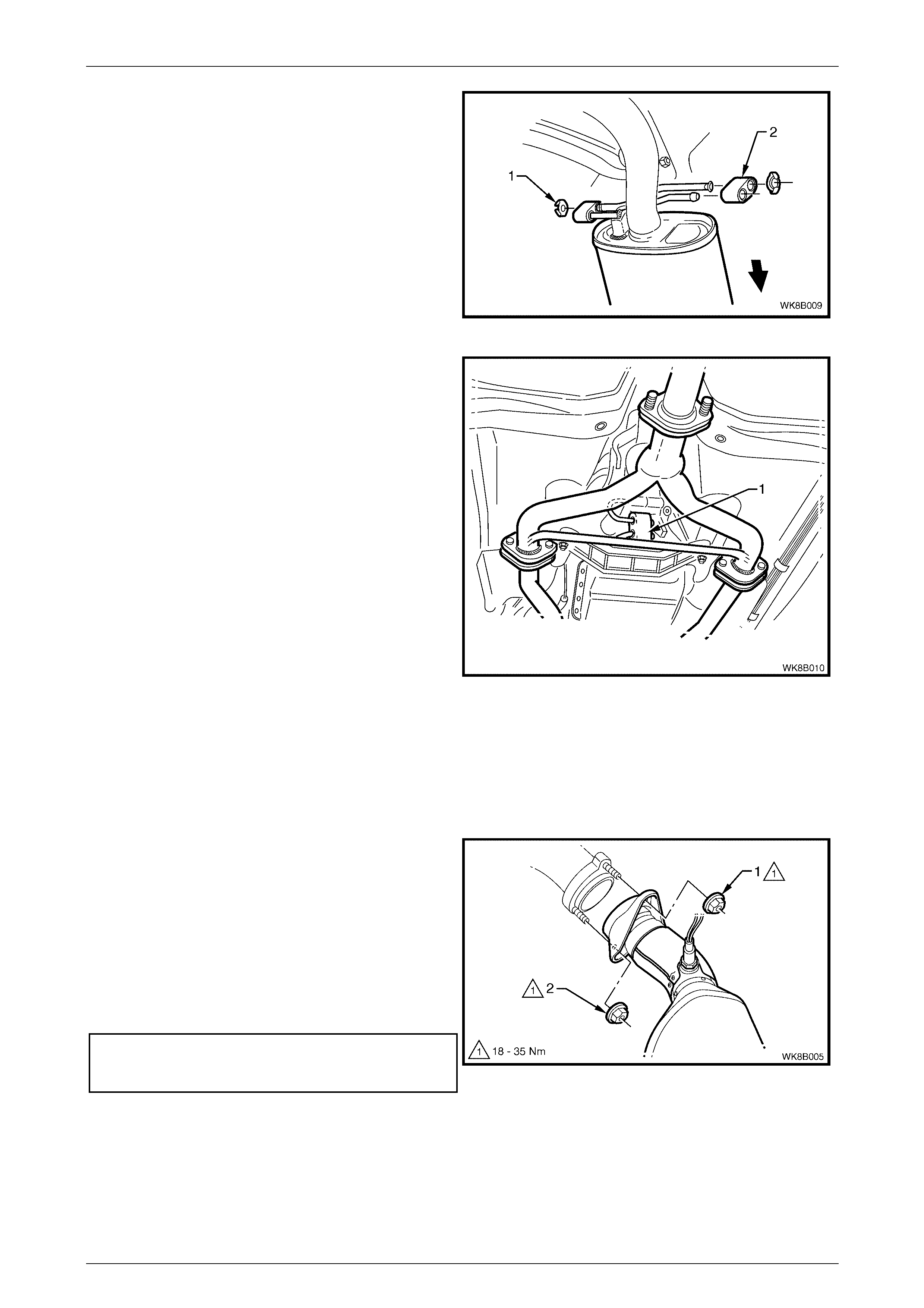
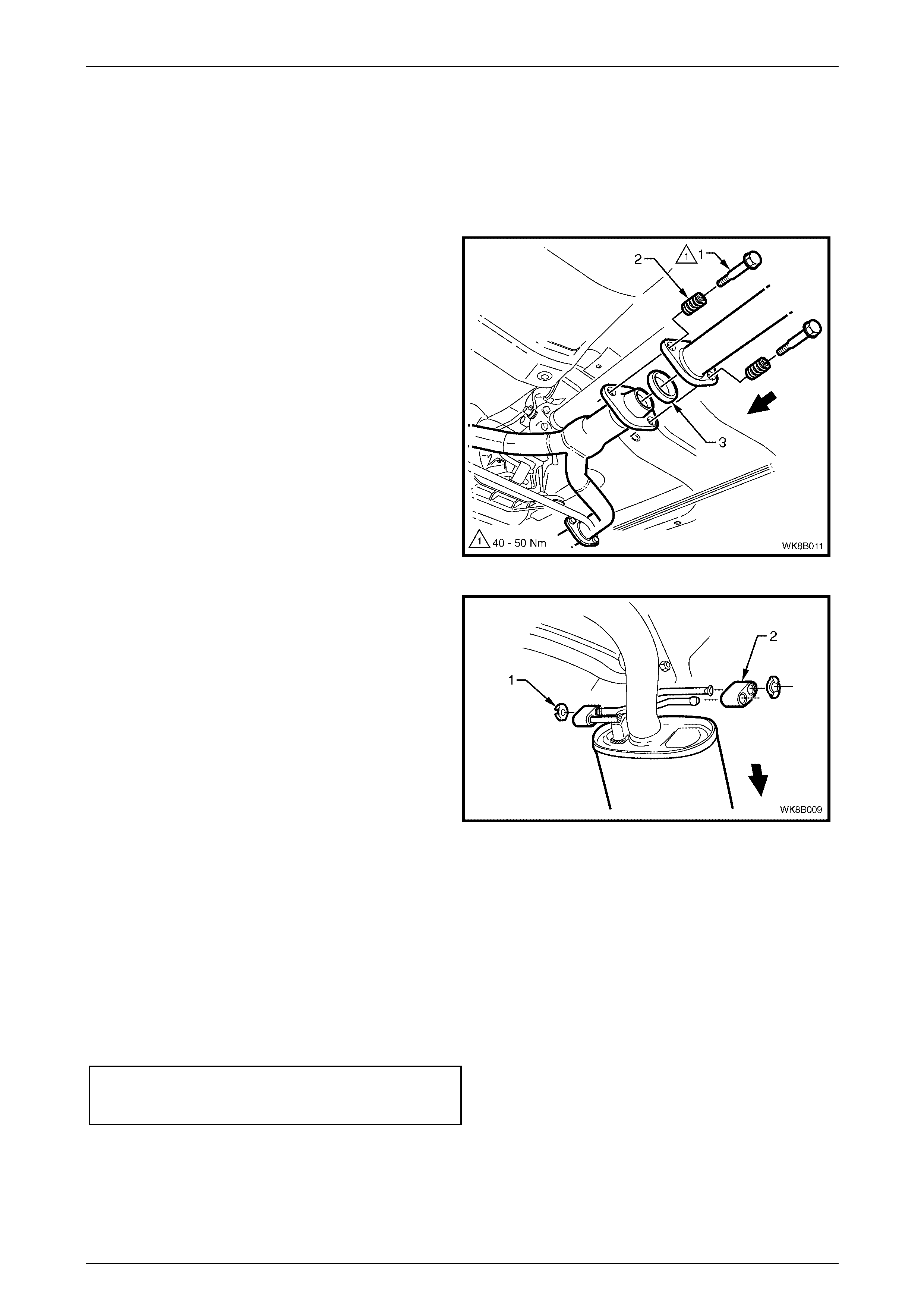
2 Support the exhaust assembly and remove the two
stepped fastening bolts (1) and springs (2) from the
intermediate single pipe and muffler assembly to
intermediate Y-pipe flange joints.
3 Separate the intermediate single pipe and muffler
exhaust assembly from the intermediate Y-pipe
exhaust assembly and remove the sealing ring (3)
from within the flange joint.
Figure 8B – 14
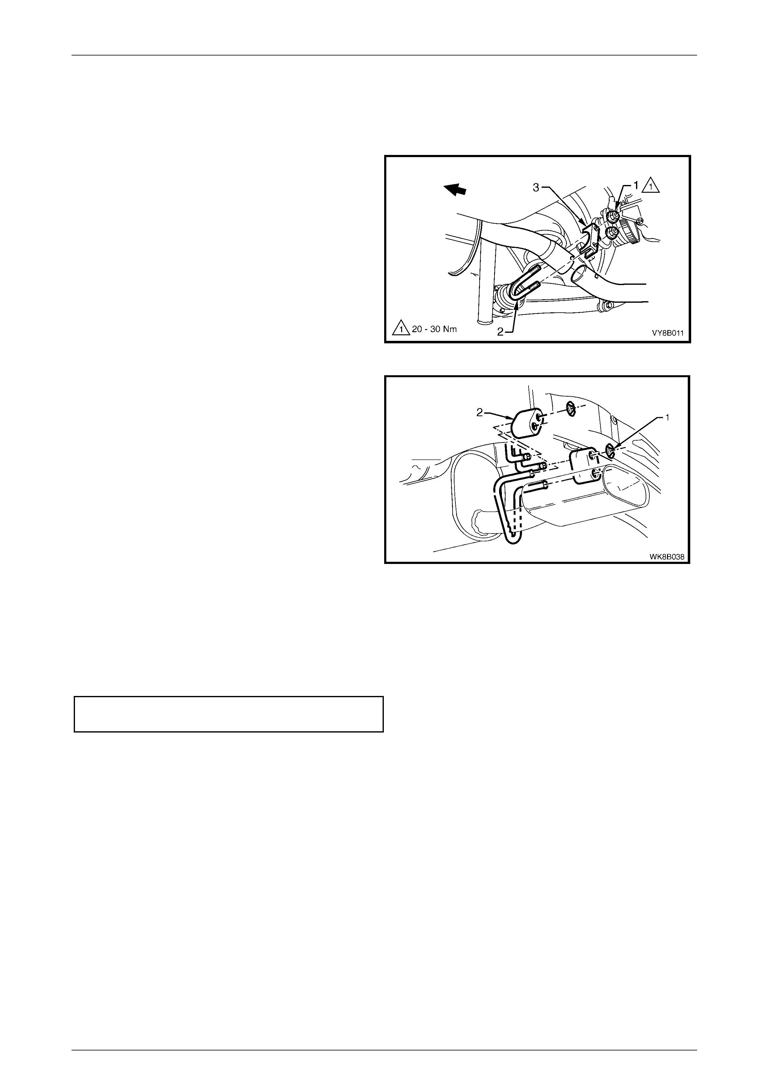
4 Remove the two retainer clips (1) and support
rubbers (2) from the support hangers and remove the
intermediate exhaust single pipe and muffler
assembly.
Figure 8B – 15
Reinstall
Installation of the intermediate exhaust single pipe and muffler assembly is the reverse of the removal procedure, noting
the following:
1 Support the exhaust system at all times.
2 Clean threads of the stepped fastening bolts and Y-pipe flange with a suitable cleaning solvent.
3 Check condition of sealing ring upon reinstallation and replace if necessary.
4 Tighten the intermediate single pipe to Y-pipe exhaust assembly flange fastening bolts to the specified torque.
Intermediate single pipe to
Y-Pipe exhaust assembly flange
fastening bolt torque specification................40 – 50 Nm
5 Ensure all support rubbers are under load.
6 Check the exhaust system for clearances, refer to 5.1 V6 Exhaust Systems Clearances. If the clearances are not
within tolerance, loosen off all fasteners and perform the tightening sequence procedure, refer to 2.7 Ti ghtening
Sequence.
Exhaust System Page 8B–13
Page 8B–13
2.5 Intermediate Exhaust Y-Pipe Assembly
Remove
1 Disconnect the wiring harness connectors from each
of the two oxygen sensors (1).
Figure 8B – 16
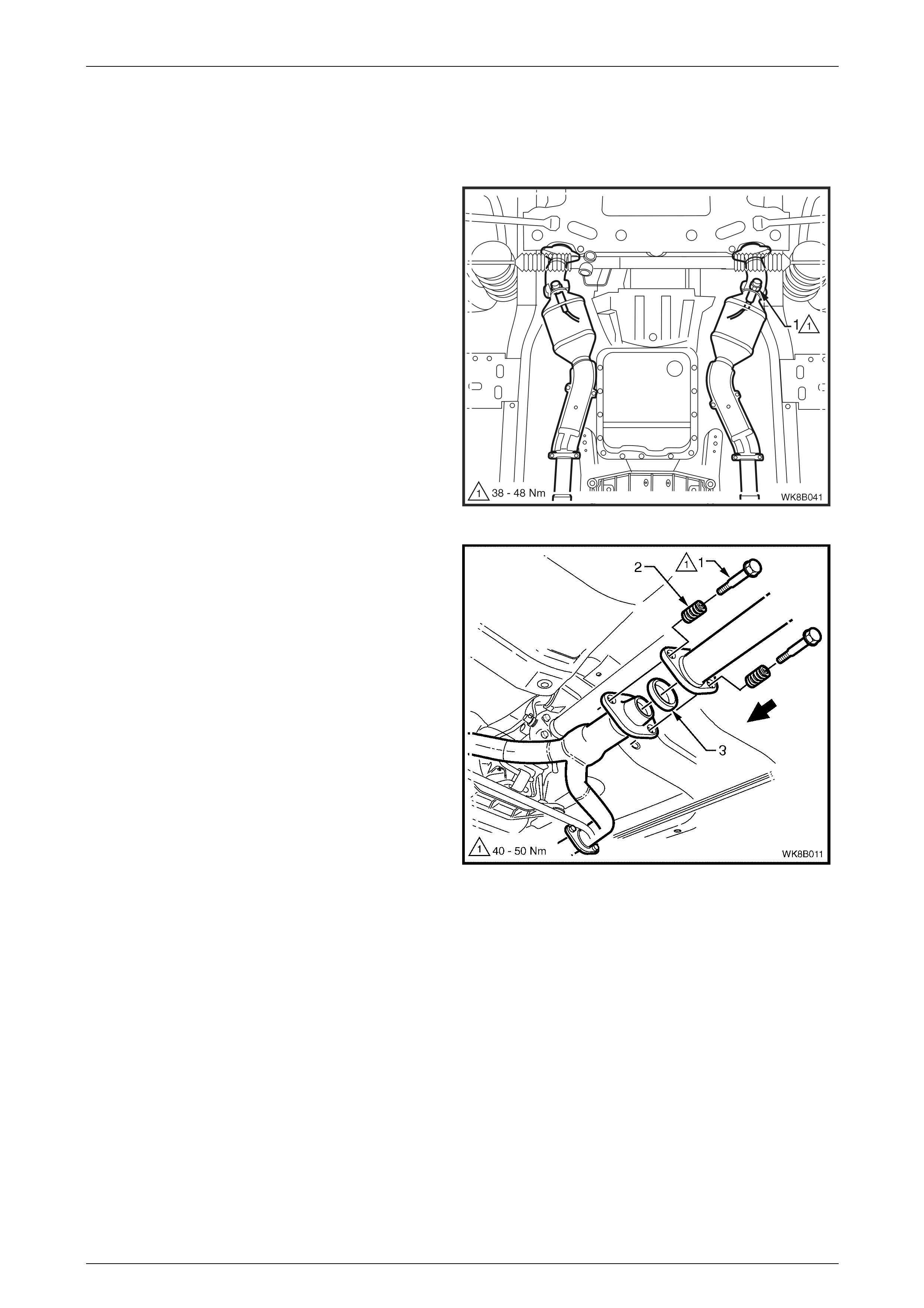
2 Support the intermediate exhaust assembly and
remove the two stepped fastening bolts (1) and
springs (2) from the intermediate exhaust single pipe
to intermediate exhaust Y-pipe flange joint.
3 Separate the intermediate single pipe and muffler
exhaust assembly and remove the sealing ring (3)
from within the flange joint.
Figure 8B – 17

Exhaust System Page 8B–14
Page 8B–14
4 Remove the two pairs of fastening nuts (1) from each
of the front two Y-pipe flange studs and remove both
flange gaskets.
5 Remove the support rubber (2) from the cross brace
peg and remove the Y-pipe exhaust assembly.
Figure 8B – 18
Reinstall
Installation of the exhaust Y-pipe assembly is the reverse of the removal procedure, noting the following points:
1 Support the exhaust system at all times.
2 Clean threads of all flange bolts and studs with a suitable cleaning solvent.
3 Always check condition of flange gaskets upon reinstallation and replace if necessary.
4 Tighten the intermediate single pipe to Y-pipe exhaust assembly flange fastening bolts to the specified torque.
Intermediate single pipe to
Y-Pipe exhaust assembly flange
fastening bolt torque specification................40 – 50 Nm
5 Tighten the front pipe to Y-pipe flange fastening bolts to the specified torque.
Front pipe to exhaust
Y-Pipe flange fastening bolt
torque specification......................................40 – 50 Nm
6 Ensure all support rubbers are under load.
7 Check the exhaust system for clearances, refer to 5.1 V6 Exhaust Systems Clearances. If the clearances are not
within tolerance, loosen off all fasteners and perform the tightening sequence procedure, refer to 2.7 Ti ghtening
Sequence.
8 Connect the wiring harness connectors for each of the two oxygen sensors.

Exhaust System Page 8B–15
Page 8B–15
2.6 Front Exhaust Assembly
Remove
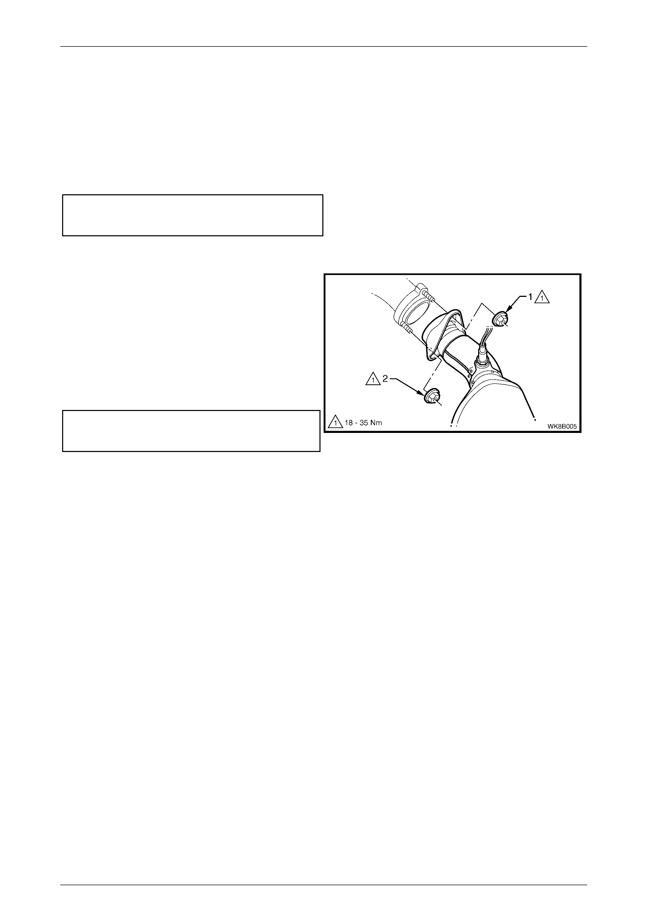
1 Disconnect the relevant wiring harness connector/s
from the oxygen sensor/s (1).
Figure 8B – 19
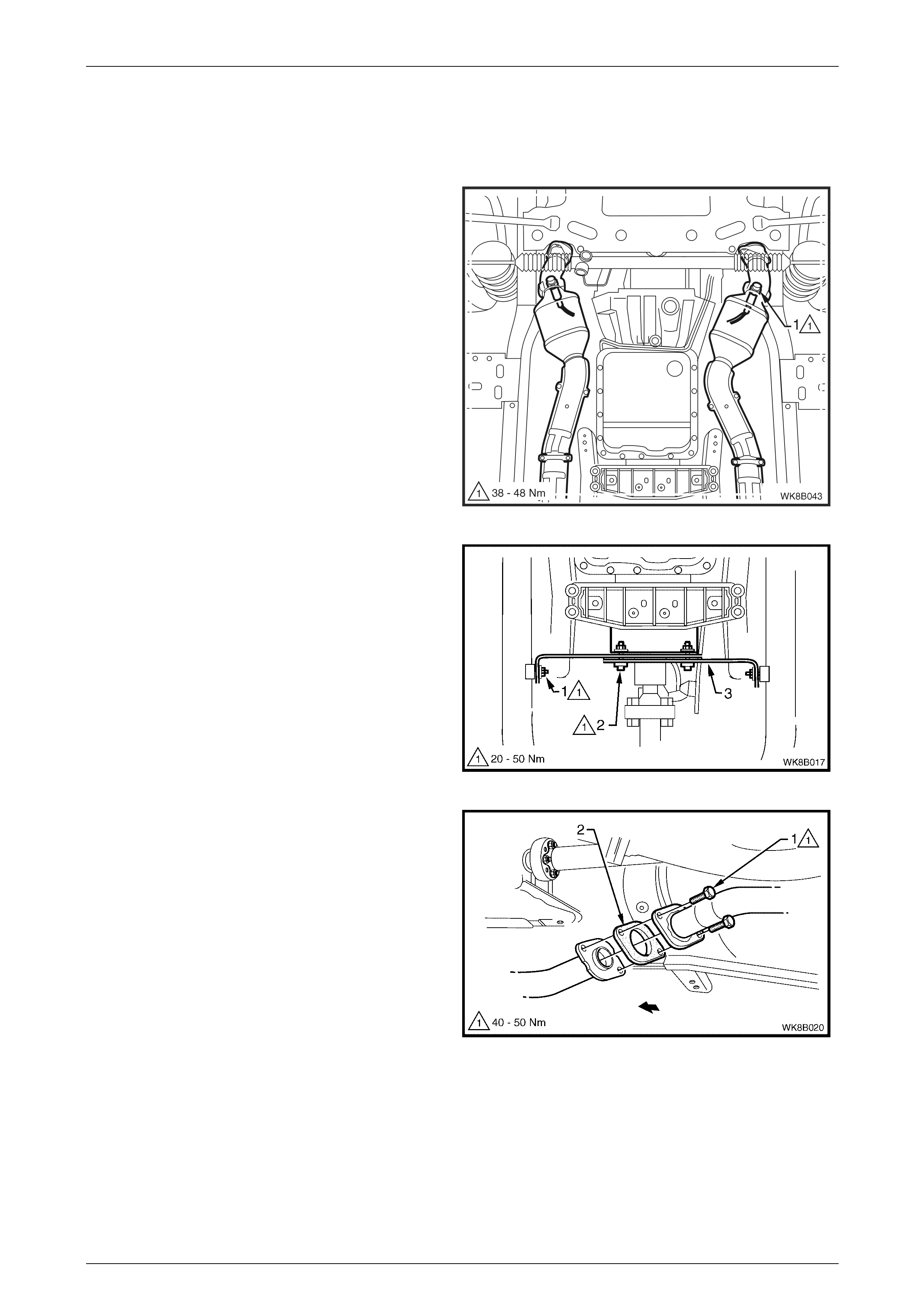
2 Support the intermediate Y-pipe exhaust assembly
and remove the necessary fastening bolts (1) from
the Y-pipe to front pipe flange joint/s.
Figure 8B – 20
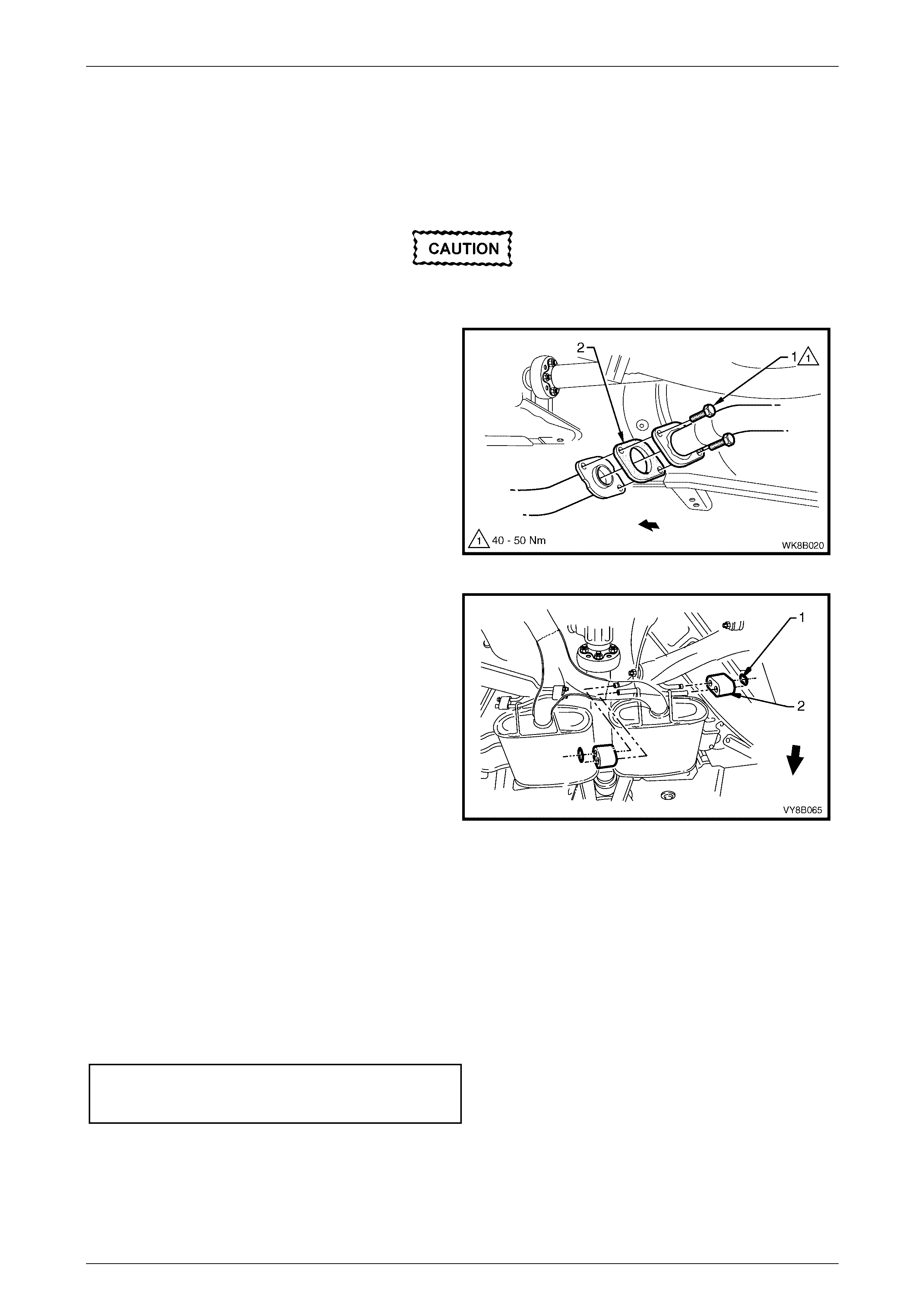
4 Support the exhaust system and remove the
upper (1) then lower (2) fastening nuts from the front
exhaust assembly to exhaust manifold flange studs
on both sides.
5 Carefully lower and remove the front exhaust
assembly from the vehicle, taking care not to damage
the exhaust gas oxygen sensor.
Figure 8B – 21
Exhaust System Page 8B–16
Page 8B–16
Reinstall
Installation of the front exhaust assembly is the reverse of the removal procedure, noting the following points:
1 Support the exhaust system at all times.
2 Clean threads of flange bolts and studs with a suitable cleaning solvent.
3 Always check condition of flange gaskets upon reinstallation and replace if necessary.
4 Tighten the intermediate Y-pipe to front exhaust assembly flange fastening bolts to the specified torque, refer to
Figure 8B – 20.
Intermediate Y-Pipe to front exhaust
assembly flange fastening bolt
torque specification......................................40 – 50 Nm
5 Apply a high temperature anti-seize compound to the exhaust manifold to exhaust pipe flange studs and align the
front pipe flange over the studs.
6 Hand tighten the upper fastening nut (1) to the stud
on both sides.
7 Hand tighten the lower fastening nut (2) to the stud
on both sides.
8 Tighten the upper then lower fastening nuts so that
approximately equal amounts of stud thread are
showing.
9 Tighten the upper then lower fastening nuts to the
specified torque.
Front exhaust assembly to exhaust
manifold flange stud fastening nut
torque specification..................................... 18 – 35 Nm
Figure 8B – 22
10 Ensure all support rubbers are under load.
11 Check the exhaust system for clearances, refer to 5.1 V6 Exhaust Systems Clearances . If the clearances are not
within tolerance, loosen off all fasteners and perform the tightening sequence procedure, refer to 2.7 Ti ghtening
Sequence.
12 Connect the wiring harness connectors for each of the two oxygen sensors.
Exhaust System Page 8B–17
Page 8B–17
2.7 Tightening Sequence
This procedure is only to be performed if the exhaust system positioning is not to specification.
Refer to Figure 8B – 24 for the following.
Ensure that all fasteners mentioned in steps 1 to 7 below are loose before conducting this procedure.
1 Tighten each of the intermediate Y-pipe to front exhaust assembly flange fastening bolts (1) to the specified
torque.
Intermediate Y-pipe to front exhaust
assembly flange fastening bolt
torque specification......................................40 – 50 Nm
2 Tighten the swivel joint flange stepped fastening bolts (2) to the specified torque.
Swivel joint flange stepped fastening
bolt torque specification ............................... 40 – 50 Nm
3 Check that the rear exhaust pipe aligning key is fully seated within the intermediate single pipe and muffler
exhaust assembly end slip joint channel. Position the U-bolt clamp (3) along the slip joint and tighten the pair of
fastening nuts to the specified torque.
U-bolt clamp assembly fastening
nuts torque specification .............................. 40 – 50 Nm
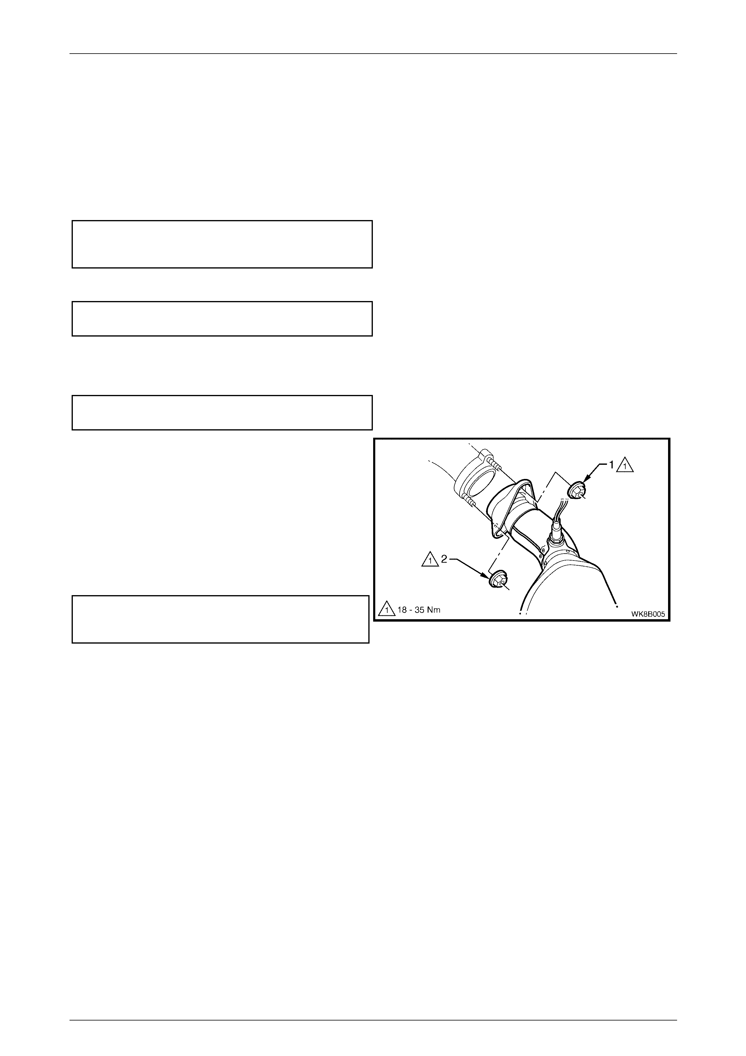
4 Hand tighten the upper fastening nut (1) to the stud
on both sides.
5 Hand tighten the lower fastening nut (2) to the stud
on both sides.
6 Tighten the upper then lower fastening nuts so that
approximately equal amounts of stud thread are
showing.
7 Tighten the upper then lower fastening nuts to the
specified torque.
Front exhaust assembly to exhaust
manifold flange stud fastening nut
torque specification..................................... 18 – 35 Nm
Figure 8B – 23
8 Ensure that all support rubbers (4, 5 and 6) are under load, refer to Figure 8B – 24. If this is not achieved, loosen
the respective joints in the reverse order to steps 1 to 7. Load the hangers and re-tighten in the sequence
described, from steps 1 to 7.
NOTE
The exhaust system should be self-aligning and
not require further adjustment, provided step 8 is
achieved. To ensure that correct clearances are
maintained throughout the complete exhaust
system, refer to 5.1 V6 Exhaust Systems
Clearances for the correct values.
Exhaust System Page 8B–18
Page 8B–18
Figure 8B – 24
Exhaust System Page 8B–19
Page 8B–19
3 Service Operations – GEN III V8
3.1 Service Notes
Two exhaust system configurations, Standard and Performance, are available for vehicles fitted with the GEN III V8
engine. The type installed will depend on the particular vehicle’s specifications. Details of both of these systems are
included.
When installing any exhaust system component, care must be taken to install each component in the correct
relationship to the other. Ensure that correct assembly, installation, tightening sequence, tightening torque and
clearance for the system involved is observed. When exhaust system service work is required, refer to the various
illustrations and instructions provided in this Section.
The incorrect assembly of exhaust system
components can frequently be the cause of
rattles and ‘booms' due to incorrect
alignment or clearance of body or suspension
parts. Ensure that the correct tightening
sequence is observed upon installation of
exhaust system components.
NOTE
Service operations on exhaust system
components must be carried out with all parts at
ambient temperatures to ensure correct
clearances are maintained.
Catalytic Converter
Catalytic converters are serviced as part of the complete front pipe assemblies only. If removing or replacing either of
the front exhaust pipe assemblies, always ensure that new flange gaskets are installed on reassembly. Check flange
gaskets for damage and replace if necessary.
Oxygen Sensors
When removing the front exhaust pipes, it is necessary to
disconnect the wiring harness connectors from each of the
two oxygen sensors (1).
For oxygen sensor replacement, refer to Section 6C3-3,
2.8 Heated Oxygen Sensors in the MY 2003 VY and V2
Series Service Information.
Figure 8B – 25
Techline
Exhaust System Page 8B–20
Page 8B–20
3.2 Exhaust System
The following removal and installation service operations should be referred to when conducting work on Standard and
Performance exhaust systems, Refer to 1.2 Exhaust System Configurations, Figure 8B – 2 and Figure 8B – 3
respectively within this Section. The illustrations provided represent the right-hand drive Standard exhaust system,
however any significant differences in procedure or configuration for left-hand drive or Performance exhaust systems will
be highlighted to accommodate servicing differences.
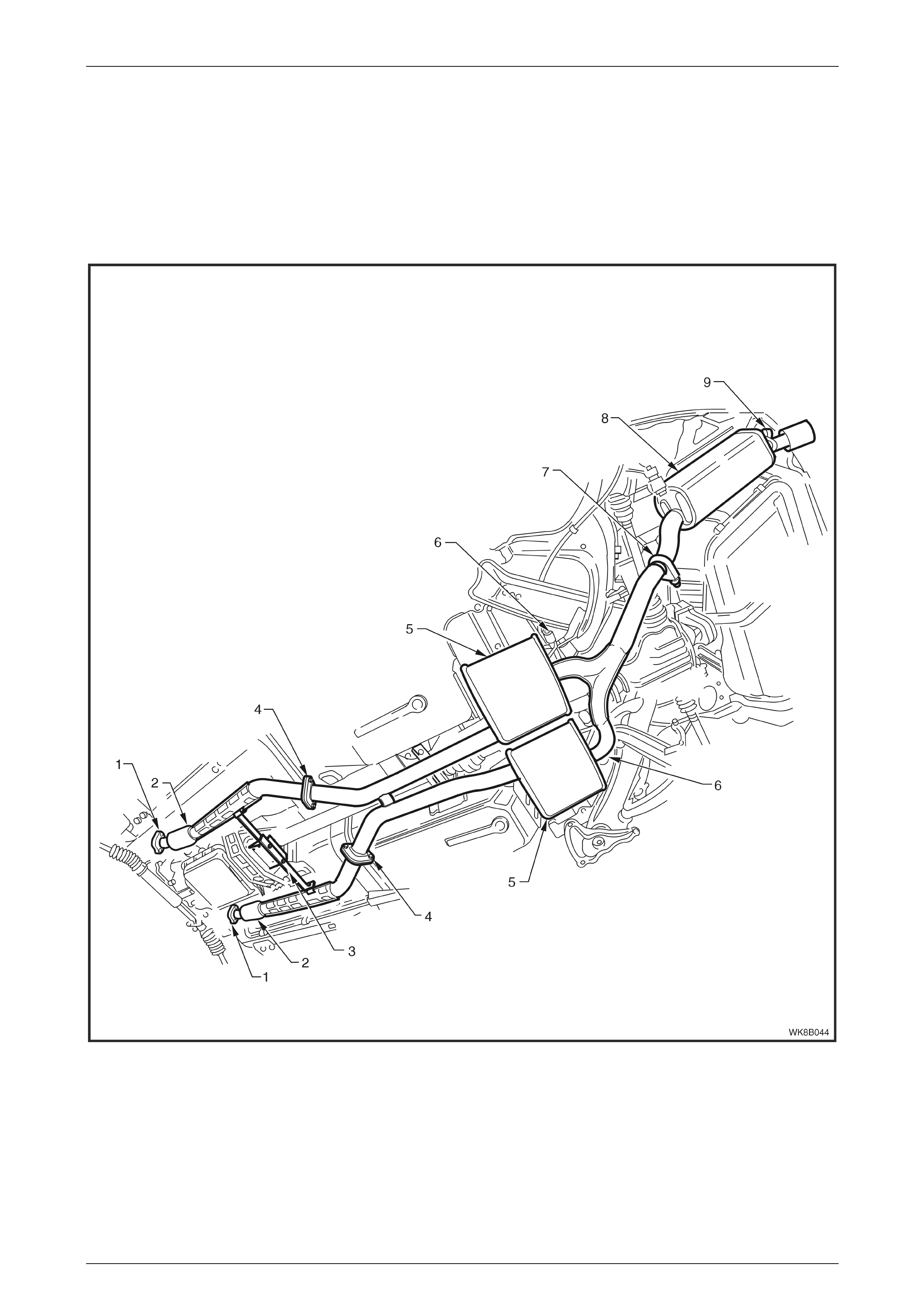
Figure 8B – 26 provides a reference to the location of relevant exhaust system removal and installation components.
Figure 8B – 26
Legend
1 Manifold to Front P i pe Fl ange J oi nt
2 Catalytic Converter
3 Transm i ssion to Front Pipe Ass embly Mounting Bracket
4 Front to Int ermediate P i pe Fl ange Joint
5 Intermediate Muffler
6 Intermediate Muff l er S upport Rubbers
7 Intermediate to Rear Pipe Slip J oi nt and Fastening
8 Rear Muffler
9 Rear Muffler Support Rubbers
Exhaust System Page 8B–21
Page 8B–21
3.3 Complete Exhaust System Assembly
Remove
1 Disconnect the wiring harness connectors from each
of the two oxygen sensors (1).
Figure 8B – 27
2 Remove the transmission to front pipe assembly
mounting bracket nuts (1 and 2).
Figure 8B – 28
3 Support the exhaust system and remove the
upper (1) then lower (2) fastening nuts from the front
exhaust assembly to exhaust manifold flange studs
on both sides.
Figure 8B – 29
Exhaust System Page 8B–22
Page 8B–22
4 Disconnect the rear muffler from the support hangers
by removing the two retainer clips (1) and support
rubbers (2).
Figure 8B – 30
5 Support the exhaust system and disconnect each
intermediate muffler from the support hangers by
removing the retainer clips (1) and the support
rubbers (2).
6 Carefully lower and remove the exhaust assembly
from the vehicle, taking care not to damage the
exhaust gas oxygen sensors.
Figure 8B – 31
Reinstall
Installation of the full exhaust system is the reverse of the removal procedure, noting the following points:
1 Support the exhaust system at all times.
2 Clean threads of flange and fastening bolts with a suitable cleaning solvent.
3 Always check condition of flange gaskets upon reinstallation and replace if necessary.
4 Apply high temperature anti-seize compound to the manifold to front pipe flange studs and align the front pipe
flange over the studs.
5 Hand tighten the upper fastening nut (1) to the stud
on both sides.
6 Hand tighten the lower fastening nut (2) to the stud
on both sides.
7 Tighten the upper then lower fastening nuts so that
approximately equal amounts of stud thread are
showing.
8 Tighten the upper then lower fastening nuts to the
specified torque.
Front exhaust assembly to exhaust
manifold flange stud fastening nut
torque specification..................................... 18 – 35 Nm
Figure 8B – 32
9 Ensure all support rubbers are under load.
10 Check the exhaust system for clearances, refer to 5.2 GEN III V8 Exhaust System Clearances . If the clearances
are not within tolerance, loosen off all fasteners and perform the tightening sequence procedure, refer to
3.7 Tightening Sequence.
11 Connect the wiring harness connectors for each of the two oxygen sensors.
Exhaust System Page 8B–23
Page 8B–23
3.4 Rear Exhaust Assembly
Remove
1 For Standard exhaust:
a Remove the two retaining nuts (1) and the rear
muffler U-bolt (2) and clamp plate (3) from the
intermediate exhaust pipe to rear muffler
exhaust pipe slip joint.
Figure 8B – 33
2 For Performance exhaust:
a Loosen each of the two ring clamp fastening
nuts.
Figure 8B – 34
3 Remove the two support hanger retainer clips (1) and
the two support rubbers (2) from the support hangers.
4 Support the intermediate exhaust assembly and slide
the rear exhaust assembly out from the intermediate
exhaust pipe end slip joint/s.
5 Remove the rear exhaust assembly.
Figure 8B – 35

Exhaust System Page 8B–24
Page 8B–24
Reinstall
Installation of the rear exhaust assembly is the reverse of the removal procedure, noting the following:
1 Ensure that the rear exhaust pipe slides unobstructed into the intermediate exhaust pipe slip joint, and that the
alignment key is positioned in the slip joint channel.
2 For Standard exhaust, evenly tighten the U-bolt clamp nuts to the correct torque specification, refer to
Figure 8B – 33.
U–bolt clamp assembly fastening
screw torque specification............................ 20 – 30 Nm
3 For Performance exhaust, position each ring clamp along the two intermediate to rear slip joints and tighten each
fastening bolt to the specified torque, refer to Figure 8B – 34.
Ring clamp assembly fastening
bolts torque specification ............................. 37 – 50 Nm
4 Ensure all support rubbers are under load.
5 Check the exhaust system for clearances, refer to 5.2 GEN III V8 Exhaust System Clearances. If the clearances
are not within tolerance, loosen off all fasteners and perform the tightening sequence procedure, refer to
3.7 Tightening Sequence.
Exhaust System Page 8B–25
Page 8B–25
3.5 Intermediate Exhaust Assembly
Remove
1 Remove the rear exhaust assembly, refer to 3.4 Rear Exhaust Assembly in this Section.
The front exhaust assembly must be
supported during and after this procedure.
2 Support the intermediate and front exhaust
assemblies and remove the two bolts (1) from each of
the two flange joints.
3 Separate the intermediate exhaust assembly from the
front exhaust assembly and remove each flange
gasket from between each of the flange joints.
Figure 8B – 36
4 Remove the pair of retainer clips (1) and support
rubbers (2) from both of the right-hand side and
left-hand side intermediate muffler support hangers
and remove the intermediate exhaust assembly.
Figure 8B – 37
Reinstall
Installation of the intermediate exhaust assembly is the reverse of the removal procedure, noting the following:
1 Support the exhaust system at all times.
2 Clean the threads of flange bolts with a suitable cleaning solvent.
3 Always check condition of flange gaskets upon reinstallation and replace if necessary.
4 Tighten the front pipe to intermediate pipe flange fastening bolts at the rear of the catalytic converters to the
specified torque.
Intermediate to front exhaust
assembly flange fastening bolt
torque specification......................................40 – 50 Nm
5 Ensure all support rubbers are under load.
5 Check the exhaust system for clearances, refer to 5.2 GEN III V8 Exhaust System Clearances. If the clearances
are not within tolerance, loosen off all fasteners and perform the tightening sequence procedure, refer to
3.7 Tightening Sequence.
Exhaust System Page 8B–26
Page 8B–26
3.6 Front Exhaust Assembly
Remove
1 Disconnect the wiring harness connector from the
relevant oxygen sensor (1).
Figure 8B – 38
2 Remove the transmission to front pipe assembly
mounting bracket nuts (1 and 2).
Figure 8B – 39
3 Support the intermediate and front exhaust
assemblies and remove the two bolts (1) from the
relevant flange joint.
4 Separate the intermediate exhaust assembly from the
front exhaust assembly and remove the flange gasket
from between the flange joint.
Figure 8B – 40
Exhaust System Page 8B–27
Page 8B–27
5 Support the front exhaust assembly and remove the
upper (1) and lower (2) fastening nuts from the
exhaust manifold to exhaust pipe flange studs on
both sides.
6 Carefully lower and remove the front exhaust
assembly from the vehicle, taking care not to damage
the oxygen sensors in the process.
Figure 8B – 41
Reinstall
Installation of the front exhaust assembly is the reverse of the removal procedure, noting the following points:
1 Support the exhaust system at all times.
2 Clean threads of flange bolts with a suitable cleaning solvent.
3 Always check condition of flange gaskets upon reinstallation and replace if necessary.
4 Apply a high temperature anti-seize compound to the manifold to front pipe flange studs and align the front pipe
flange over the studs.
5 Install the upper fastening nut (1) to the stud on both
sides.
6 Install the lower fastening nut (2) to the stud on both
sides.
7 Tighten the upper and lower fastening nuts so that
approximately equal amounts of thread are showing.
8 Tighten the exhaust manifold to front pipe flange
fastening nuts (1 and 2) to the specified torque.
Front exhaust assembly to exhaust
manifold flange stud fastening nut
torque specification..................................... 18 – 35 Nm
Figure 8B – 42
9 Tighten the front pipe to intermediate pipe flange fastening bolts to the specified torque, refer to Figure 8B – 40.
Intermediate to front exhaust
assembly flange fastening bolt
torque specification......................................40 – 50 Nm
10 Tighten the transmission to front pipe assembly mounting bracket nuts to the specified torque, refer to
Figure 8B – 39.
Transmission to front pipe
assembly mounting bracket nut
torque specification......................................20 – 50 Nm
11 Ensure all support rubbers are under load.
12 Check the exhaust system for clearances, refer to 5.2 GEN III V8 Exhaust System Clearances . If the clearances
are not within tolerance, loosen off all fasteners and perform the tightening sequence procedure, refer to
3.7 Tightening Sequence.
13 Connect the wiring harness connector to the relevant oxygen sensor.

Exhaust System Page 8B–28
Page 8B–28
3.7 Tightening Sequence
This procedure is only to be performed if the exhaust system positioning is not to specification.
Refer to Figure 8B – 44 for the following:
NOTE
Ensure that all fasteners mentioned in steps 1
to 8 are loose before conducting this procedure.
1 Tighten the intermediate to front exhaust assembly flange fastening bolts (1) to the specified torque.
Intermediate to front exhaust
assembly flange fastening bolt
torque specification......................................40 – 50 Nm
2 For a Standard exhaust system, check that the rear exhaust pipe aligning key is seated within the channel
provided in the intermediate exhaust pipe’s end slip joint. Position the U-bolt clamp along the intermediate to rear
slip joint and tighten the pair of fastening nuts (2) to the specified torque.
U–bolt clamp assembly fastening
nut torque specification................................20 – 30 Nm
3 For a Performance exhaust system, position each ring clamp along the two intermediate to rear slip joints and
tighten each fastening nut to the specified torque.
Ring clamp assembly fastening nut
torque specification......................................37 – 50 Nm
4 Hand tighten the upper fastening nut (1) to the stud
on both sides.
5 Hand tighten the lower fastening nut (2) to the stud
on both sides.
6 Tighten the upper then lower fastening nuts so that
approximately equal amounts of stud thread are
showing.
7 Tighten the upper then lower fastening nuts to the
specified torque.
Front exhaust assembly to exhaust
manifold flange stud fastening nut
torque specification..................................... 18 – 35 Nm
Figure 8B – 43
8 Tighten the cross brace to exhaust front pipe nuts (3) to the specified torque.
Cross brace to front pipe assembly
mounting bracket nut torque specification ... 20 – 50 Nm
9 Tighten the cross brace bracket nuts (4) to the specified torque.
Cross brace bracket fastening
nut torque specification................................20 – 50 Nm
10 Ensure that all six support rubbers (5 and 6) are under load, refer to Figure 8B – 44. If this is not achieved, loosen
the respective joints in the reverse order to steps 1 to 9. Load the hangers and re-tighten in the sequence
described, from steps 1 to 9.
NOTE
The exhaust system should be self-aligning and
not require further adjustment, provided step 10
is achieved. To ensure that correct clearances
are maintained throughout the full exhaust
system, refer to 5.2 GEN III V8 Exhaust System
Clearances for the correct values.
Exhaust System Page 8B–29
Page 8B–29
Figure 8B – 44

Exhaust System Page 8B–30
Page 8B–30
4 Service Operations – Exhaust
System Heat Shields
4.1 Heat Shields
Should any of the heat shields require replacement, the following procedure is recommended.
To avoid the possibility of personal injury by
burns, allow the exhaust system to cool down
before attempting this operation.
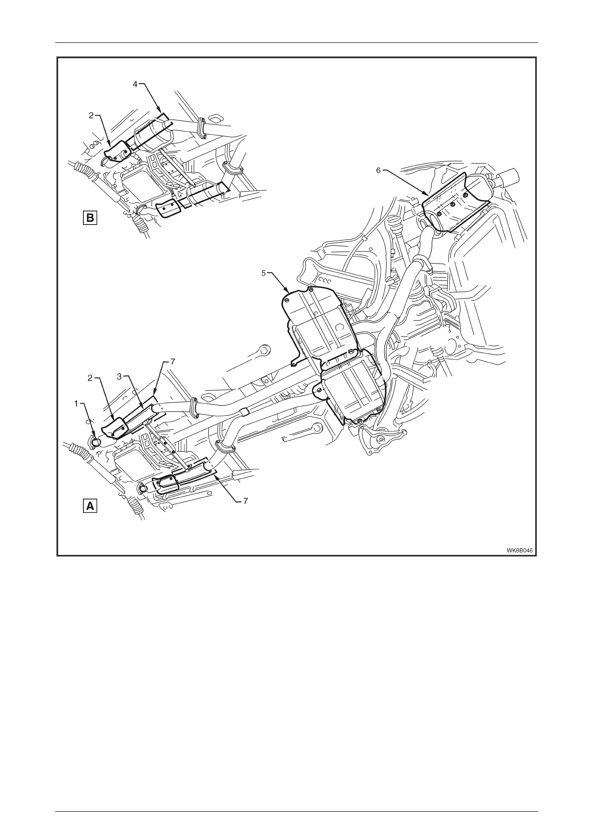
Figure 8B – 45 provides a reference to the location of heat shields fitted to all WK Series vehicles.
Exhaust System Page 8B–31
Page 8B–31
Figure 8B – 45
Legend
A Configuration – V6 and GEN III
V8
B Configurati on – V 6 S /C
1 Pre Catalyt i c Converter On-pipe Heat
Shield
2 Front Foil Heat S hi el d
3 Post Cat al ytic Converter On-pi pe Heat
Shield
4 Long Butyl Patch Underfloor Heat Shield
5 Intermediate Heat Shields
6 Rear Heat Shiel d
7 Short Butyl Patc h Underfloor Heat
Shield
Exhaust System Page 8B–32
Page 8B–32
Rear Muffl er Underbody Mounted Heat Shield
Remove
1 If required, remove the rear exhaust assembly, refer to the following:
• 2.3 Rear Exhaust Assembly for V6.
• 3.4 Rear Exhaust Assembly for GEN III V8.
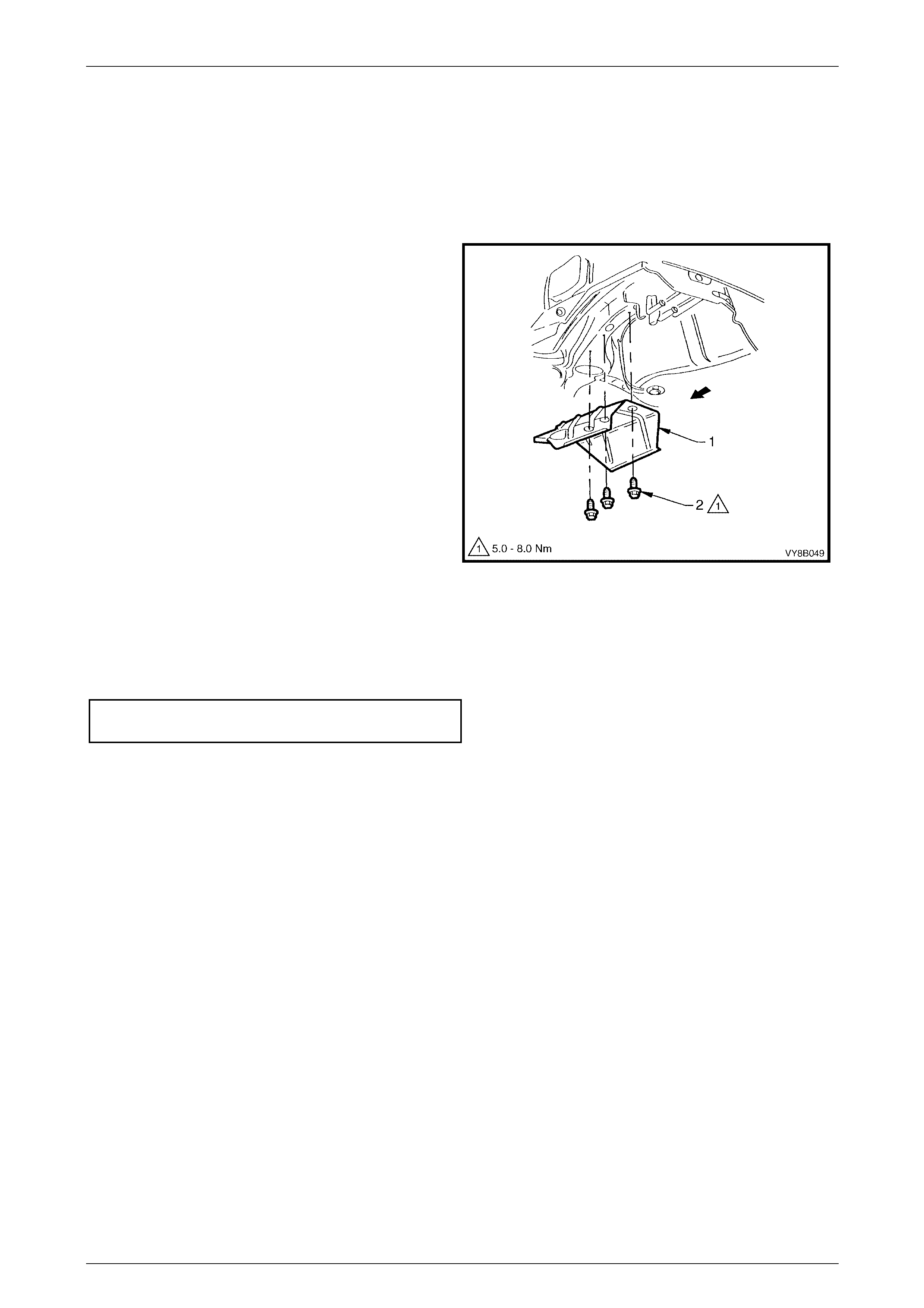
2 Remove the rear muffler heat shield (1) by removing
the three fastening screws (2).
Figure 8B – 46
Reinstall
Installation of the rear muffler heat shield is the reverse of the removal procedure, noting the following:
1 Tighten the body fastening screws to the correct torque specification:
Rear muffler heat shield fastening
screw torque specification.......................... 5.0 – 8.0 Nm
Exhaust System Page 8B–33
Page 8B–33
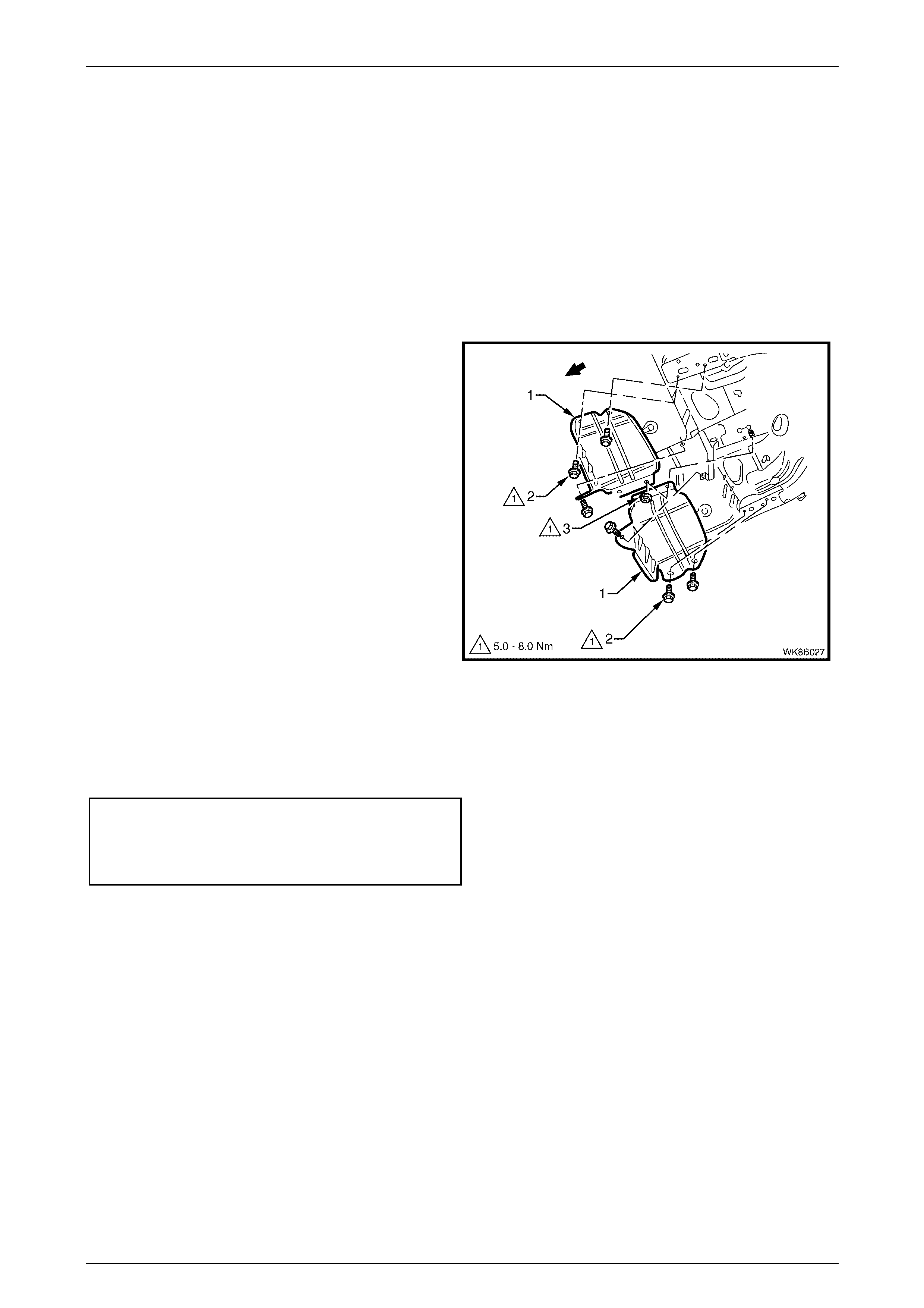
Intermediat e M uf f ler Underbody Mounted Heat Shield
Remove
1 If required, remove the intermediate exhaust assembly, refer to:
• 2.4 Intermediate Exhaust Single Pipe and Muffler Assembly for V6.
• 3.5 Intermediate Exhaust Assembly for GEN III V8.
NOTE
For V6 vehicles, there is only one intermediate
muffler heat shield; installed above the single
intermediate muffler.
2 Remove the intermediate heat shields (1) by
removing the fastening screws (2) and the single stud
nut (3).
Figure 8B – 47
Reinstall
Installation of the intermediate heat shield is the reverse of the removal procedure, noting the following:
1 Tighten the body fastening screws (2) and stud nut (3) to the correct torque specification, refer to Figure 8B – 47.
Intermediate muffler heat shield
fastening screw torque specification..........5.0 – 8.0 Nm
Intermediate muffler heat shield
stud fastening nut torque specification.......5.0 – 8.0 Nm
Exhaust System Page 8B–34
Page 8B–34
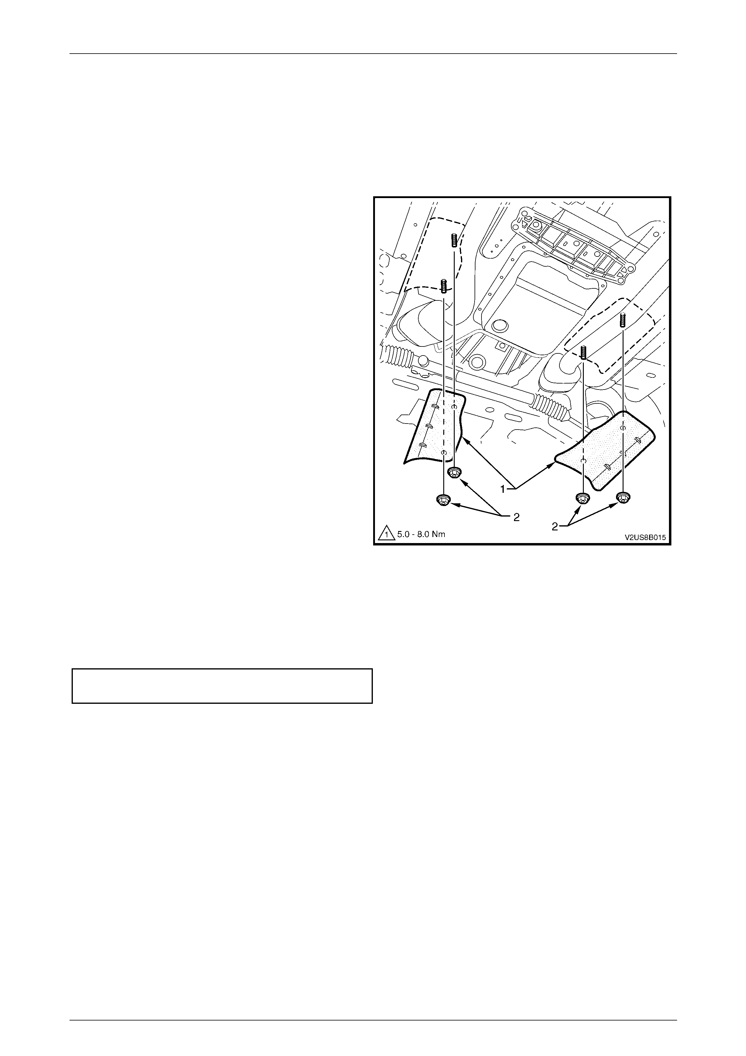
Front Exhaust Assembly Underbody Mount ed Heat Shi elds
Remove
1 If required, remove the front exhaust assembly, refer to:
• 2.6 Front Exhaust Assembly for V6.
• 3.6 Front Exhaust Assembly for GEN III V8.
2 Remove the front underbody mounted heat
shields (1) by removing each of the fastening
nuts (2).
Figure 8B – 48
Reinstall
Installation of the intermediate heat shield is the reverse of the removal procedure, noting the following:
1 Tighten the front underbody mounted heat shield fastening nuts (2) to the correct torque specification, refer to
Figure 8B – 48.
Front underbody mounted heat shield
fastening nut torque specification .............. 5.0 – 8.0 Nm
Exhaust System Page 8B–35
Page 8B–35
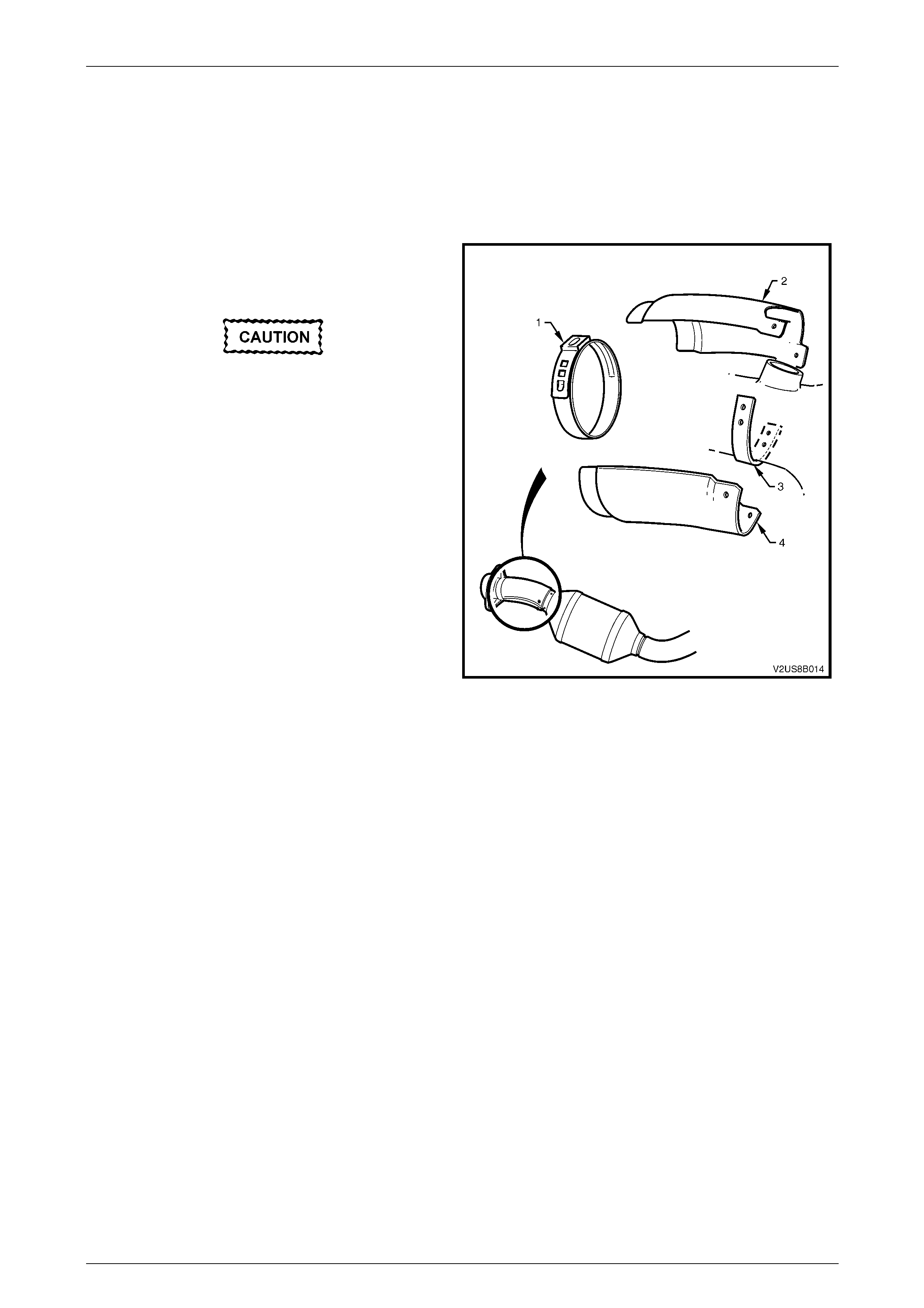
Front Exhaust Assembly On-pipe Heat Shields – Pre Cat al ytic Converter
Remove
1 If required, remove the front exhaust assembly, refer to:
• 2.6 Front Exhaust Assembly for V6.
• 3.6 Front Exhaust Assembly for GEN III V8.
2 Use special tool J22610 to cut through the ear (1) of
the ear-type clamp and remove and dispose of
clamp.
Do not use excessive force when drilling
out heat shield rivets. Excessive force
may result in the drill being pushed into
and piercing the exhaust pipe
underneath.
3 Drill out each of the four rivets securing the upper
and lower facing on-pipe heat shields (2 and 4) to
the welded-on exhaust pipe bracket (3).
Figure 8B – 49
Reinstall
Installation of the on-pipe heat shields is the reverse of the removal procedure, noting the following:
1 Rivet on the upper and lower on-pipe heat shields (2 and 4) onto the front exhaust pipe bracket (3), refer to
Figure 8B – 49.
2 Install a new ear-type clamp (1) by hand and crimp to fasten using special tool J22610, refer to Figure 8B – 49.
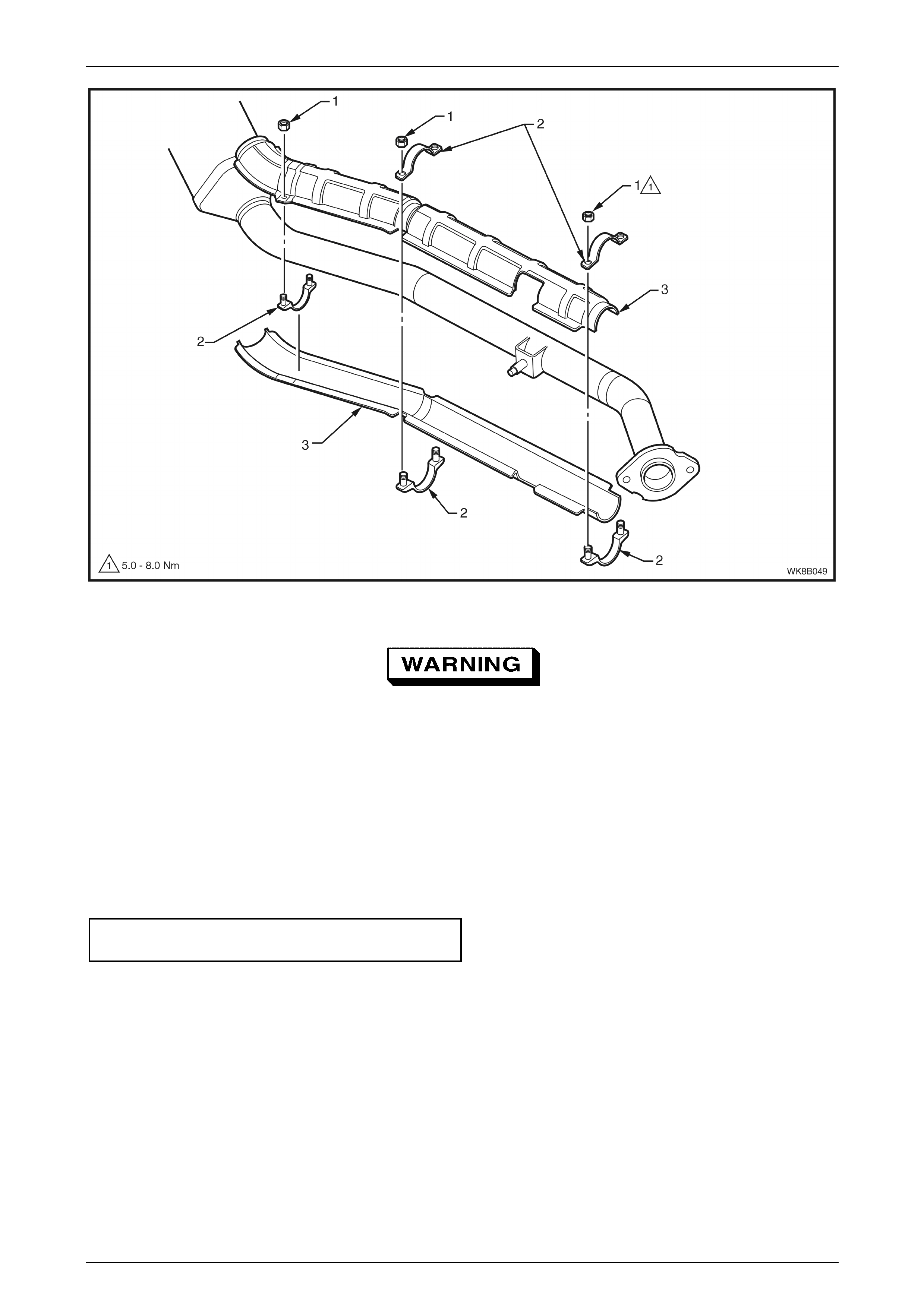
Front Exhaust Assembly On-pipe Heat Shields - Post Catalytic Converter
NOTE
Figure 8B-50 shows GEN III V8 long on-pipe
heat-shield. For V6 and GEN III V8 produced
after 11 September 2003 short op-pipe
heatshields are used. Similar removal and
installation procedures are used for both.
Remove
1 If required, remove the front exhaust assembly, refer to:
• 2.6 Front Exhaust Assembly for V6.
• 3.6 Front Exhaust Assembly for GEN III V8
Exhaust System Page 8B–36
Page 8B–36
Figure 8B – 50
The lower heat shield and clamps will drop
away from exhaust w hen all attaching nuts (1)
are removed.
2 Supporting the lower heat shield, remove the attaching nuts (1) and clamps (2), refer to Figure 8B – 50.
3 Remove the lower and upper heat shield (3).
Reinstall
Installation of the on-pipe heat shields is the reverse of the removal procedure, noting the following:
1 Tighten each of the on-pipe heat shield attaching nuts (1) to the correct torque specification.
Post catalytic converter on-pipe heat shield
attaching nut torque specification .................... 5 – 8 Nm
Exhaust System Page 8B–37
Page 8B–37
Butyl Patch Reflective Foil Heat Shields – V6 Supercharged Only
Remove
1 If required, remove the front exhaust assembly, refer to Section 8B Exhaust System, 3 Service Operations -
V6 Supercharged in the MY2003 VY and V2 Service Information for removal and reinstallation procedures.
2 Peel the butyl patch reflective foil insulators (1) to be
replaced from the under floor and discard.
3 Use a solvent soaked rag to remove all traces of the
old insulator adhesive, sealer overspray or paint
overspray, should the vehicle have been repaired.
Reinstall
NOTE
Do not attempt to re-use a removed butyl patch
reflective foil insulator. Always use a new part.
1 Use a solvent soaked rag to remove all traces of the
old insulator adhesive, sealer overspray or paint
overspray, should the vehicle have been repaired.
2 Heat a new butyl reflective foil insulator to 40 ± 5° C.
Figure 8B – 51
3 Wearing heat resistant protective gloves, peel the
adhesive protective paper from the new butyl
reflective foil insulator and apply the insulator to the
cleaned under floor area in the same position as the
removed part. The edge of the patch should align
with the edge of the longitudinal flange (1). Smooth
out any air bubbles in the process.
Figure 8B – 52
Exhaust System Page 8B–38
Page 8B–38
5 Exhaust System Clearances
5.1 V6 Exhaust Systems Clearances
The following diagrams indicate the exhaust system clearances specified for vehicles fitted with the V6 engine.
Clearances should be checked upon installation of exhaust components to prevent parts interference and ensure
correct alignment. Refer to Figure 8B – 5 for the location of exhaust system parts.
To avoid the possibility of personal injury,
allow the exhaust system to cool dow n before
attempting this operation.
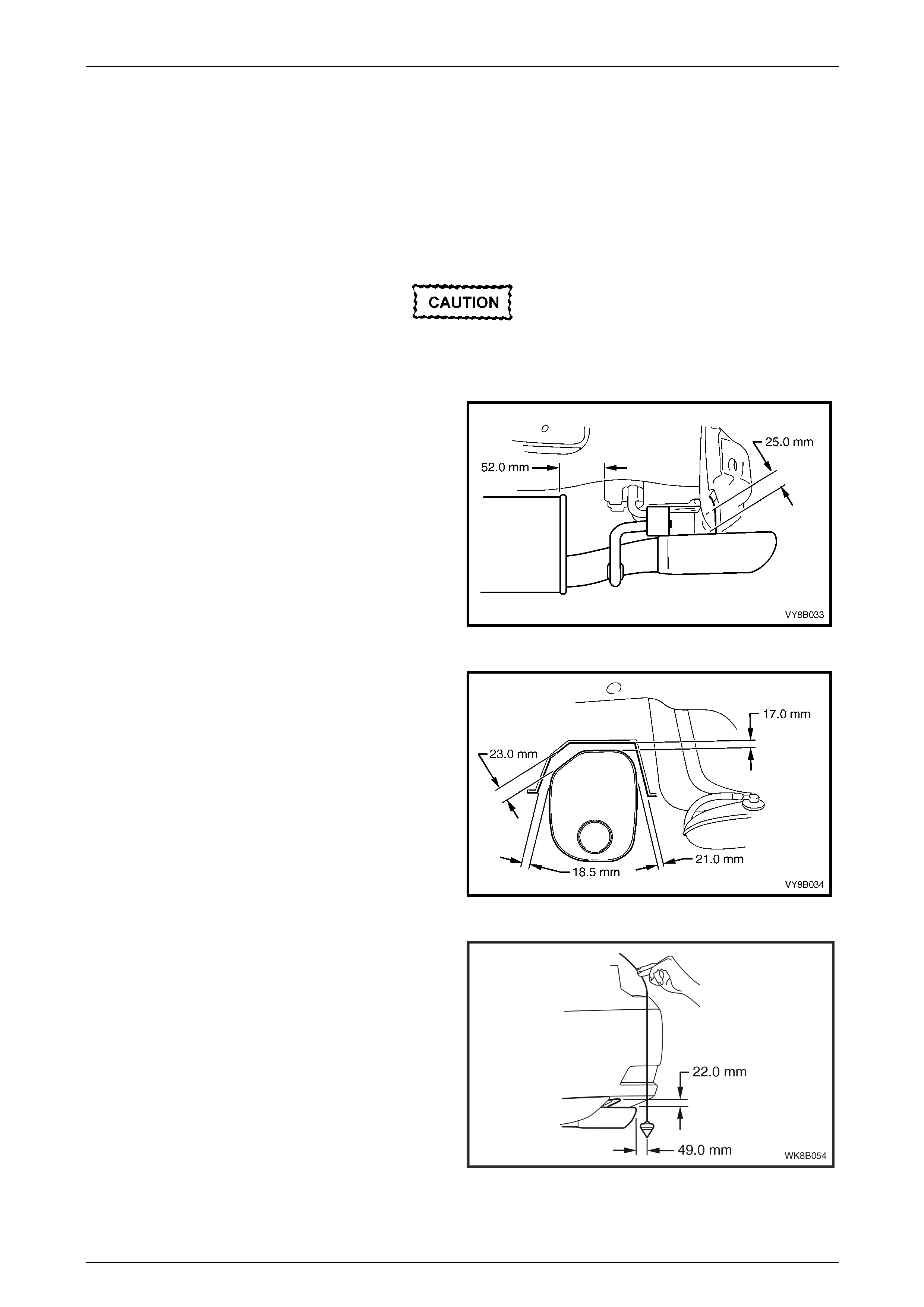
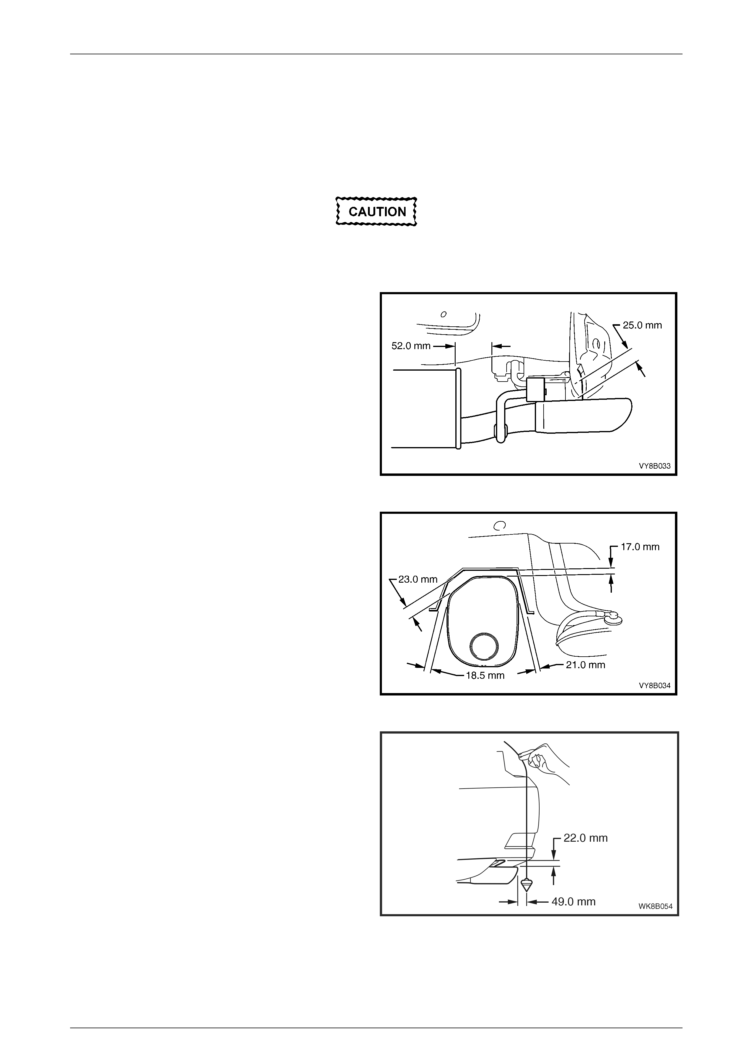
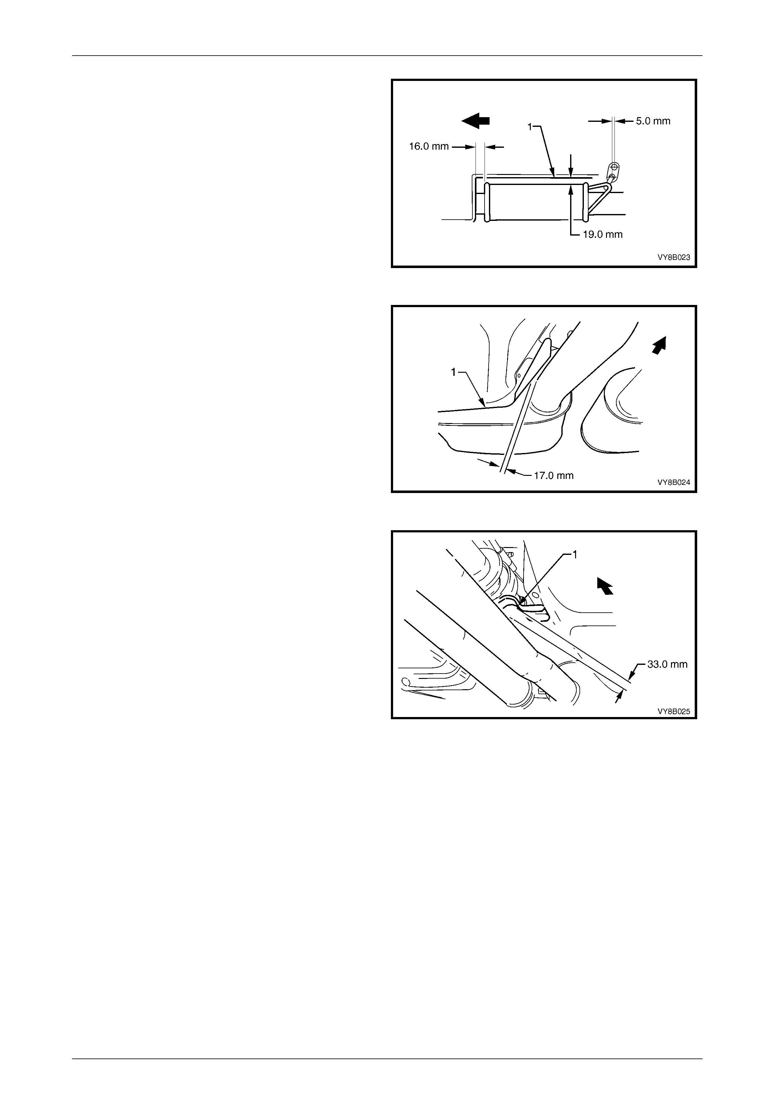
1 Check the rear tail pipe to rear end panel clearances
and rear muffler to tail pipe hanger mounting
clearances.
Figure 8B – 53
2 Check the rear exhaust muffler to rear heat shield
clearances.
Figure 8B – 54
3 Check the clearance between the rear tail pipe
exhaust tip and the underside of the bumper fascia.
4 Holding a weighted string over the rear bumper fascia,
in line with the exhaust tip, determine the horizontal
clearance between the exhaust tip and rear bumper.
Figure 8B – 55
Exhaust System Page 8B–39
Page 8B–39
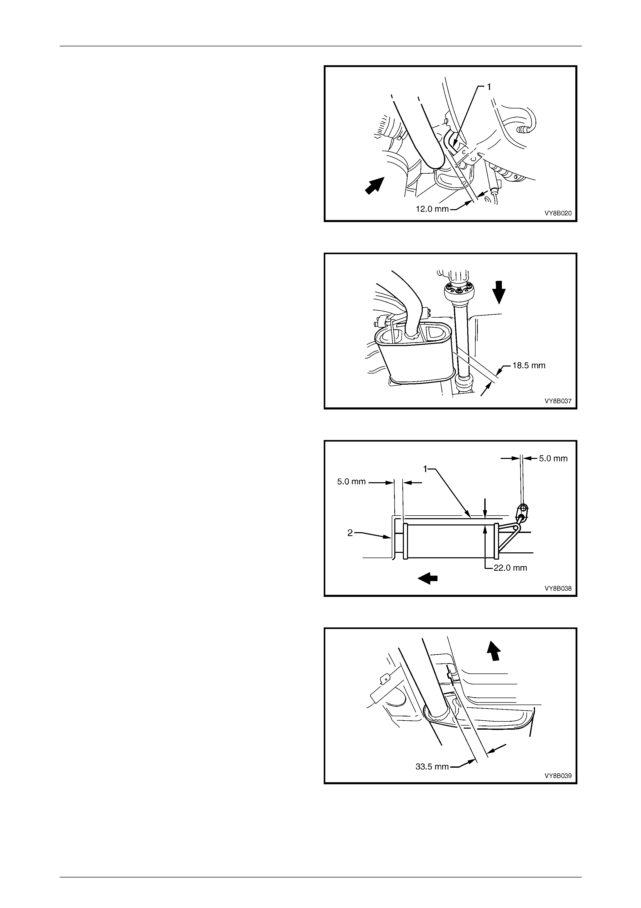
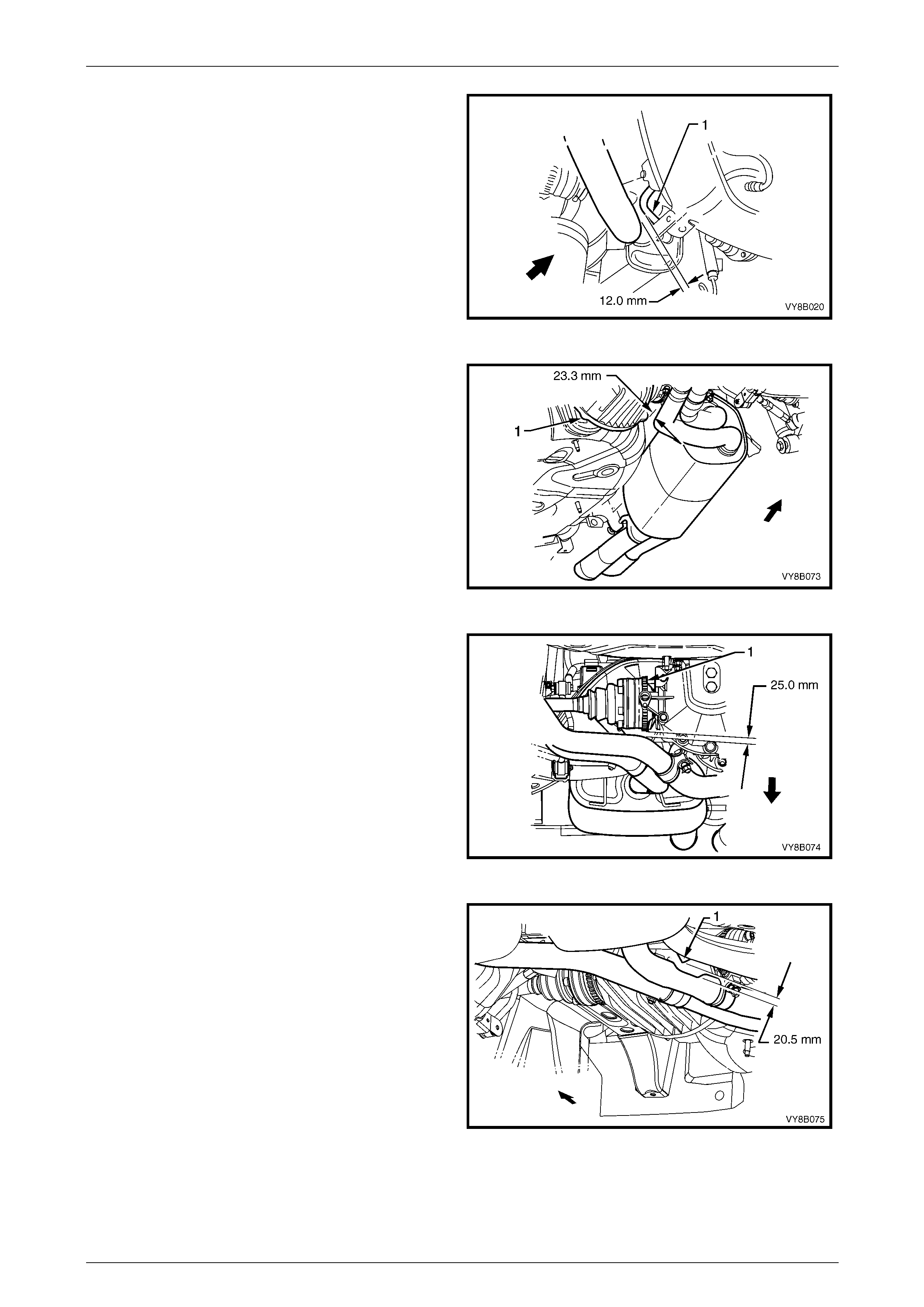
5 Check the intermediate to rear exhaust pipe to
stabiliser bar linkage (1) clearances.
Figure 8B – 56
6 Check the intermediate exhaust hanger to propeller
shaft clearances.
Figure 8B – 57
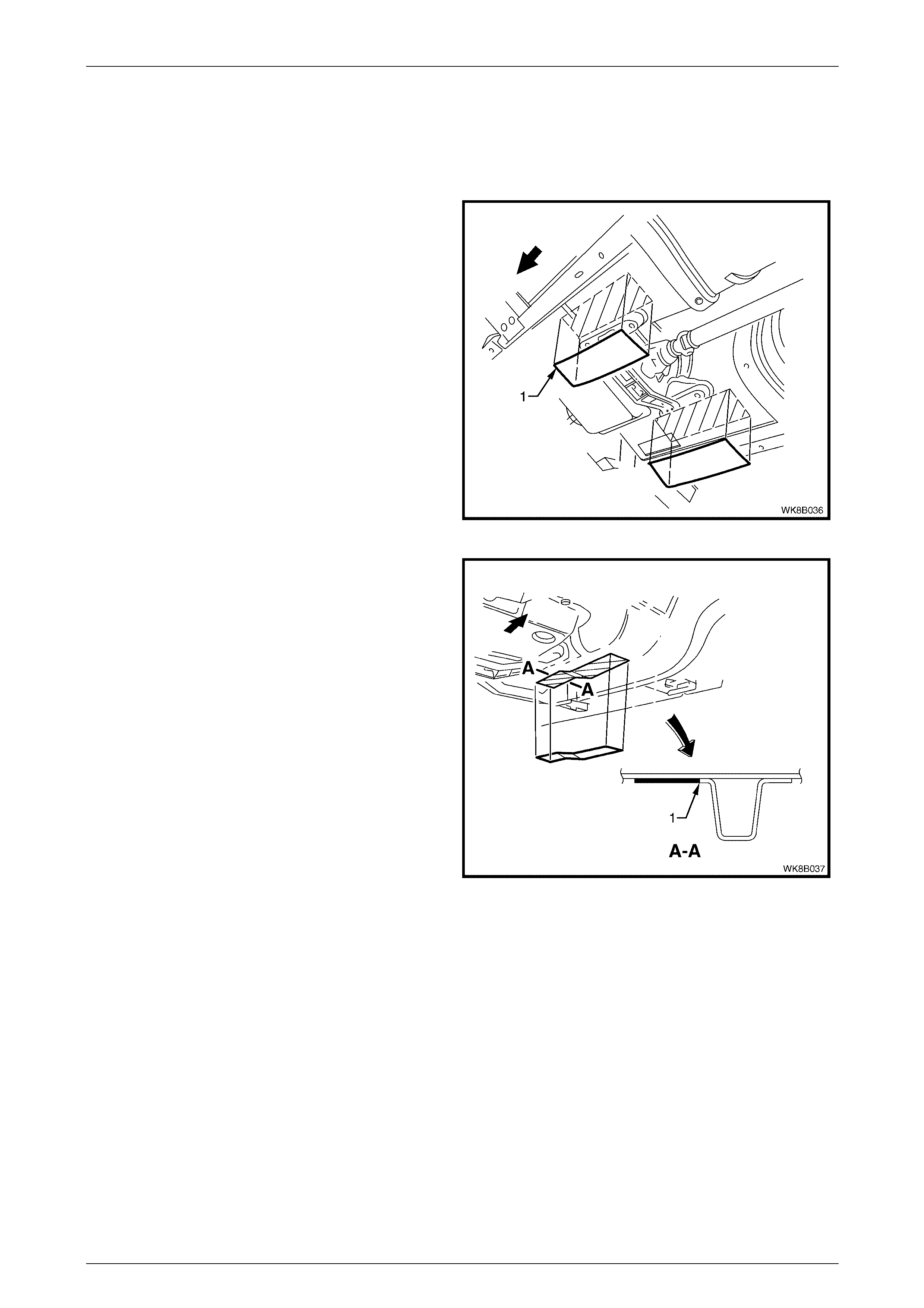
7 Check intermediate exhaust muffler to intermediate
heat shield (1) and rear footwell (2) clearances;
nominal clearance provided. The horizontal clearance
provided between the body hanger and support peg is
for reference only.
Figure 8B – 58
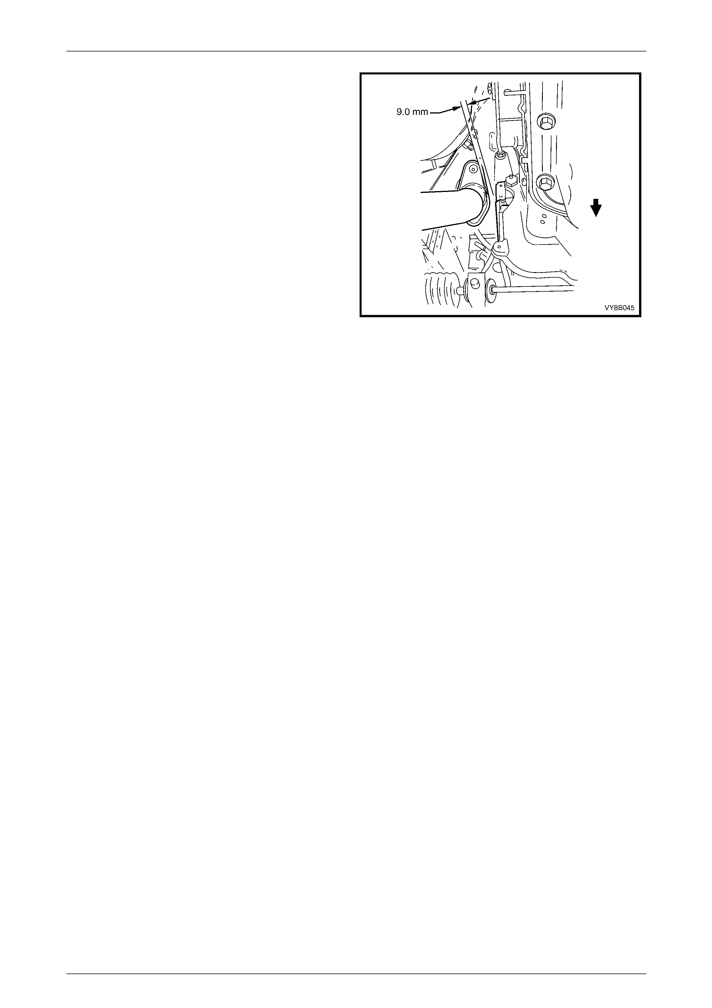
8 Check the intermediate exhaust pipe to intermediate
heat shield clearances.
Figure 8B – 59
Exhaust System Page 8B–40
Page 8B–40
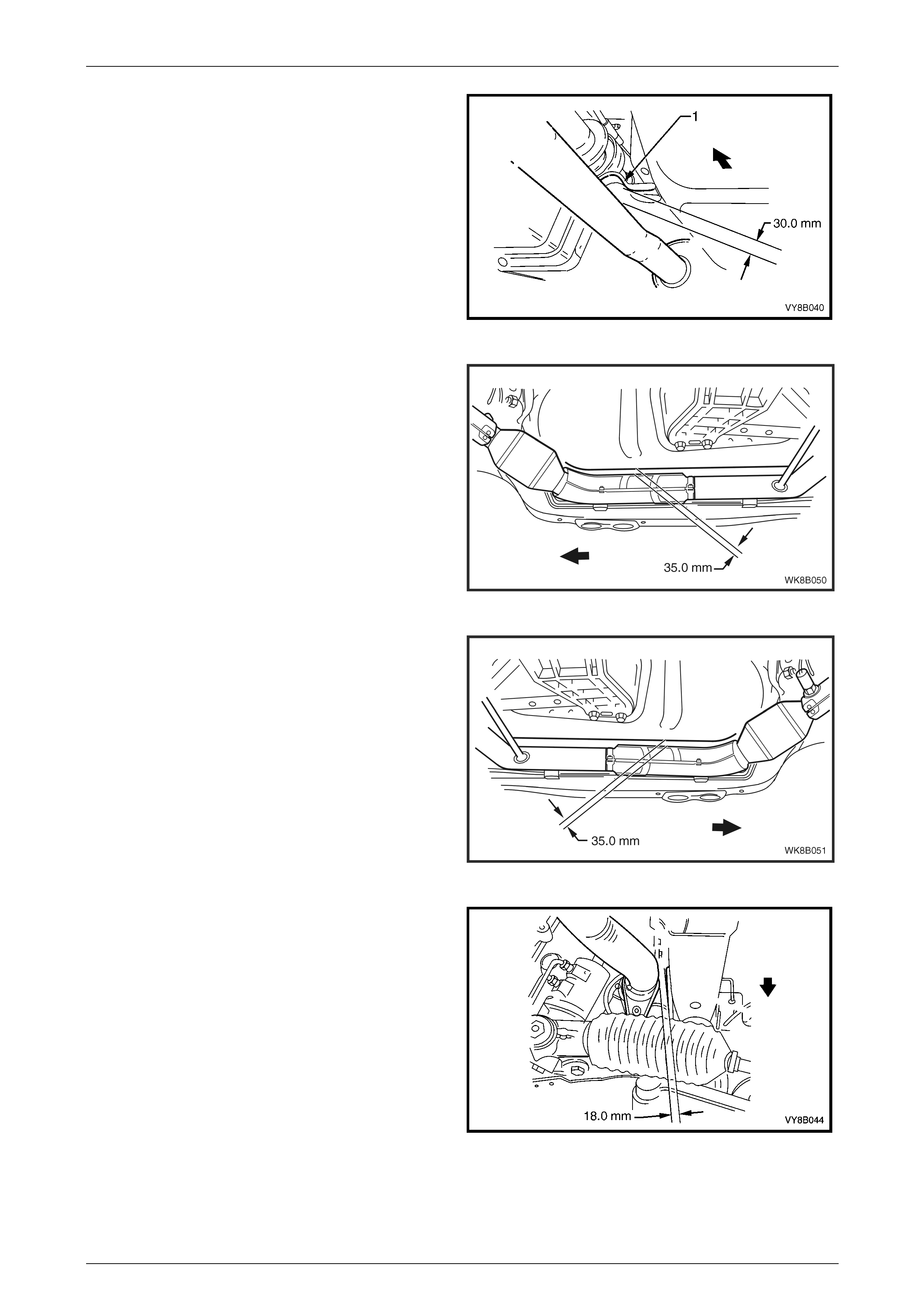
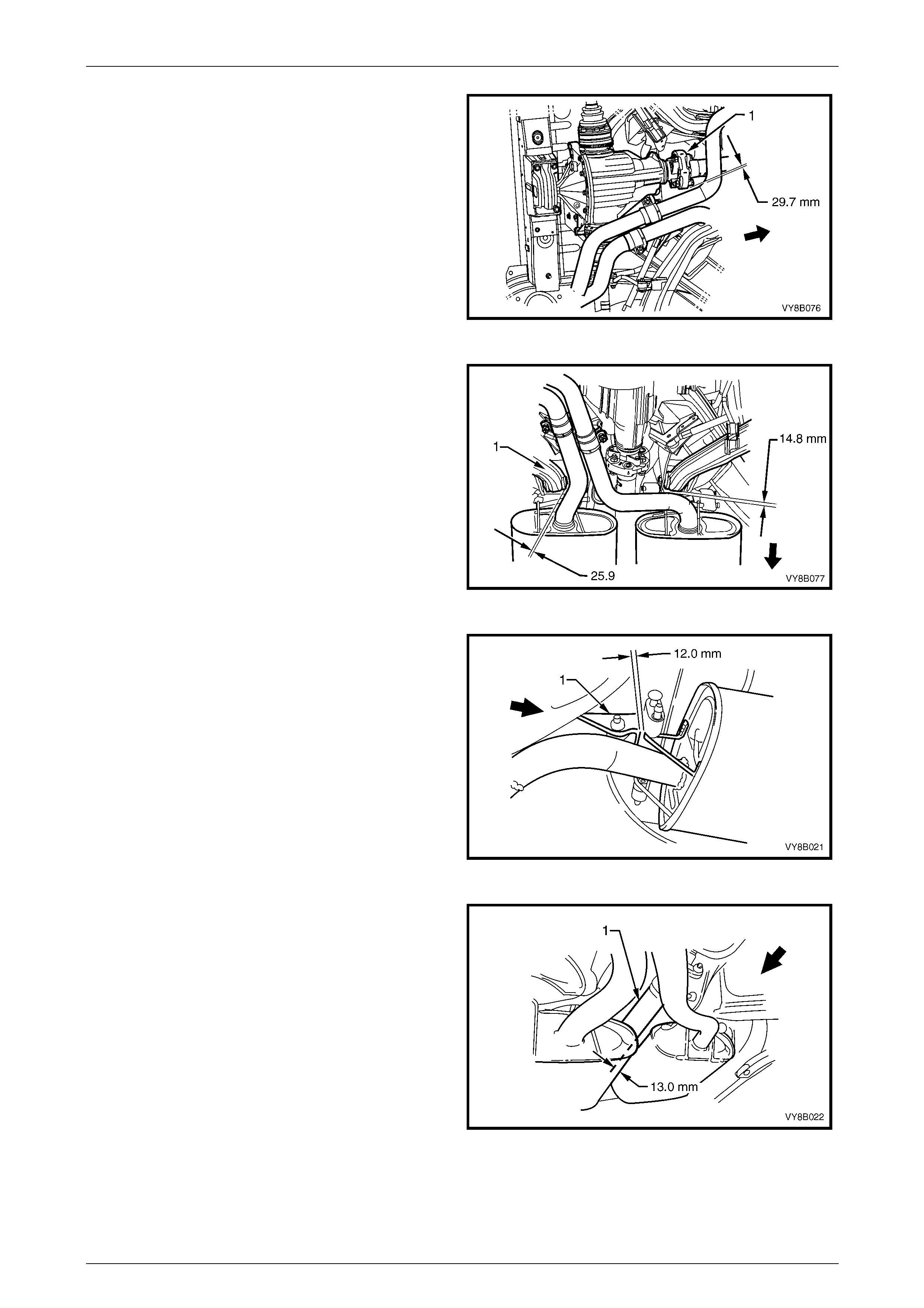
9 Check the intermediate exhaust pipe to centre bearing
carrier (1) clearance.
Figure 8B – 60
10 Check the right-hand side front exhaust pipe to
underbody foot well clearances. Nominal clearance
provided.
Figure 8B – 61
11 Check the left-hand side front exhaust pipe to
underbody foot well clearances. Nominal clearance
provided.
Figure 8B – 62
12 Check the clearance between the front exhaust pipe
and the front longitudinal assembly clearance.
Figure 8B – 63
Exhaust System Page 8B–41
Page 8B–41
13 Check the front left-hand side exhaust pipe to engine
block clearances.
Figure 8B – 64
Exhaust System Page 8B–42
Page 8B–42
5.2 GEN III V8 Exhaust System Clearances
The following diagrams indicate the exhaust system clearances specified for vehicles fitted with the Gen III V8 Engine.
Both standard and performance type exhaust systems are included. Clearances should be checked upon installation of
exhaust components to prevent parts interference and ensure correct parts alignment. Refer to Figure 8B – 26 for
GEN III V8 part locations.
To avoid the possibility of personal injury,
allow the exhaust system to cool dow n before
attempting this operation.
1 Check the rear tail pipe to body panel clearances and
rear muffler to tail pipe hanger mount clearances.
Figure 8B – 65
2 Check the rear exhaust muffler to heat shield
clearances.
Figure 8B – 66
3 Check the clearance between the rear tail pipe
exhaust tip and the underside of the bumper fascia.
4 Holding a weighted string over the rear bumper fascia,
in line with the exhaust tip, determine the horizontal
clearance between the exhaust tip and rear bumper.
Figure 8B – 67
Exhaust System Page 8B–43
Page 8B–43
5 Check the rear intermediate exhaust pipe to stabiliser
bar linkage (1) clearances.
Figure 8B – 68
6 Check the rear exhaust pipe to differential carrier (1)
clearances.
Figure 8B – 69
7 Check the rear exhaust pipe to inner axle shaft (1)
clearances.
Figure 8B – 70
8 Check the intermediate exhaust pipe to suspension
member (1) clearances.
Figure 8B – 71
Exhaust System Page 8B–44
Page 8B–44
9 Check the intermediate exhaust pipe to rubber
coupling (1) clearances.
Figure 8B – 72
10 Check the intermediate exhaust pipe to suspension
cross member elbow (1) clearances.
Figure 8B – 73
11 Check the intermediate exhaust hanger to underbody
mounting (1) clearances.
Figure 8B – 74
12 Check the intermediate exhaust muffler to propeller
shaft (1) clearances.
Figure 8B – 75
Exhaust System Page 8B–45
Page 8B–45
13 Check the intermediate exhaust muffler to
intermediate heat shield (1) clearances.
NOTE
The clearance between the intermediate exhaust
muffler and the horizontal section of the heat
shield is nominal.
Figure 8B – 76
14 Check the intermediate exhaust pipe to intermediate
heat shield clearances.
Figure 8B – 77
15 Check the intermediate exhaust pipe to centre bearing
carrier (1) clearances.
Figure 8B – 78

Exhaust System Page 8B–46
Page 8B–46
16 Check the front exhaust pipe to engine block (1)
clearances.
Figure 8B – 79

Exhaust System Page 8B–47
Page 8B–47
6 Exhaust System Diagnosis
CONDITION PROBABLE CAUSE CORRECTION
Leaks at pipe joints. Tighten U-bolt nuts, ring
clamps and joint bolts to the
specified torques.
Damaged or improperly installed
converter sealing ring/gaskets. Replace sealing ring/gasket
as necessary.
Leaking exhaust gases
Burned or rusted out exhaust pipe
or muffler/s. Replace component as
necessary.
Leaks at manifold or pipe
connections.
Tighten clamps at leaking
connections to specified
torques. Replace gasket as
required.
Burned or blown out pipe or
muffler/s. Replace pipe/muffler
assembly as necessary.
Exhaust manifold/s cracked or
broken. Replace manifold.
Exhaust noises
Leak between manifold/s and
cylinder head/s.
Tighten manifold to cylinder
head studs to specified
torque.
Clogged catalytic converter (may
result from serious engine
malfunction). Replace catalytic converter.
Loss of engine power,
hesitation, surging, poor fuel
economy, stalling or hard
starting Crushed pipe work. Replace pipe work.
Dislodged tubes and/or baffles in
muffler. Replace muffler.
Internal rattling in muffler Catalytic converter monolith has
crumbled and pieces blown into
muffler.
Replace catalytic converter
assembly and affected
muffler.
Damaged, worn, missing or
improperly installed support
rubbers.
Check and replace as
necessary.
Damaged mounting hangers or
pegs. Service / replace hangers or
pegs as necessary.
Check clearances and adjust
joint alignment as necessary.
Improper alignment. Tighten all fasteners
according to tightening
sequence and the specified
torques.
Rattling or knocking exhaust
system
Damaged or incorrect exhaust
system components.
Replace damaged or
incorrect components as
necessary.

Exhaust System Page 8B–48
Page 8B–48
7 Specifications
Type
V6
Dual front pipes with individual close coupled catalytic
converters incorporated along each front pipe. One
intermediate muffler and one rear muffler.
V6 Supercharged
Dual system to rear of twin intermediate mufflers with
a single pipe rear muffler/tailpipe arrangement.
Individual catalytic converters incorporated along
each front pipe.
GEN III V8 Standard
Dual system to rear of twin intermediate mufflers with
a single pipe rear muffler/tailpipe arrangement.
Individual close coupled catalytic converters
incorporated along each front pipe.
GEN III V8 Performance
Dual system back to a single rear muffler with dual tail
pipes. Front pipes similar to those used on standard
type GEN III V8 exhaust system.
Material
Engine Pipes
....................................................................................................................409 stainless steel
Intermediate Muffler
....................................................................................................................409 stainless steel
Rear Muffler
....................................................................................................................409 stainless steel
Catalytic Converter
Make
............................................................................................................................. AC Australia
Type
..................................................................................................................Three way monolith
Outer Steel Shell
....................................................................................................................409 stainless steel
Monolith Material
...................................................................................................................Extruded Cordierite
Cells/cm2
............................................................................................................................................. 62

Exhaust System Page 8B–49
Page 8B–49
8 Torque Wrench Specifications
Intermediate to front exhaust assembly swivel-joint
flange stepped fastening bolt...........................................................40 – 50 Nm
Cross brace to front pipe assembly mounting bracket
fastening nut....................................................................................20 – 50 Nm
Cross brace bracket fastening nut...................................................20 – 50 Nm
U-bolt clamp assembly fastening nuts.............................................20 – 30 Nm
Front exhaust assembly to exhaust manifold flange
stud fastening nut............................................................................18 – 35 Nm
Intermediate to rear exhaust assembly flange joint
fastening bolts .................................................................................40 – 50 Nm
Intermediate to front exhaust assembly flange fastening bolt .........40 – 50 Nm
Intermediate Y–pipe to front exhaust assembly
flange fastening bolt ........................................................................40 – 50 Nm
Ring clamp assembly fastening nut.................................................37 – 50 Nm
Rear muffler heat shield fastening screw ......................................5.0 – 8.0 Nm
Intermediate muffler heat shield fastening screw..........................5.0 – 8.0 Nm
Intermediate muffler heat shield stud fastening nut.......................5.0 – 8.0 Nm
Front exhaust assembly heat shield fastening screw....................5.0 – 8.0 Nm
Post catalytic converter on-pipe heat shield attaching nut ............5.0 – 8.0 Nm

Exhaust System Page 8B–50
Page 8B–50
9 Special Tools
Tool Number Illustration Description Tool Classification
J22610
KEYSTONE CLAMP PLIERS
Used to tighten ear-type clamps. Essential