
SECTION 0A - GENERAL INFORMATION
1. PRECAUTIONS
1.1 SUPPLEMENTAL RESTRAINT SYSTEM
PRECAUTIONS
Diagnosis
Servicing and Handling
1.2 GENERAL PRECAUTIONS
1.3 PRECAUTIONS FOR CATALYTIC
CONVERTER
1.4 PRECAUTIONS FOR INSTALLING
MOBILE COMMUNICATION
EQUIPMENT
1.5 PRECAUTION IN SERVICING FULL-TIME
4WD VEHICLES
1.6 PRECAUTIONS FOR ELECTRICAL
CIRCUIT SERVICE
1.7 ELECTRICA L CIRCUIT INSPECTION
PROCEDURE
Open Circuit Check
Continuity Check
Voltage Check
Short Circuit Check (Wire Harness
to Ground)
Intermittents and Poor Connections
2. IDENTIFICATION INFORMATION &
PLATES
2.1 VEHICLE IDENTIFICATION NUMBER
2.2 ENGINE IDENTIFICATION NUMBER
2.3 TRANSMISSION IDENTIFICATION
NUMBER
2.4 SAFETY COMPLIANCE PLATE
2.5 BODY & OPTION IDENTIFICATION
PLATE
2.6 TA G PLATE
3. WARNING, CAUTION AND INFORMATION
LABELS
4. LIFTING POINTS
Using a Hoist
Using a Floor Jack
5. ABBREVIATIONS AND SYMBOLS USED IN
THIS MANUAL
Abbreviations
Symbols
Wire Colour Symbols
6. FASTENER INFORMATION
6.1 METRIC FASTENERS
6.2 FASTENER STRENGTH
IDENTIFICATION
6.3 STANDARD TIGHTENING TORQUE
Tightening Torque Chart
7. CONSOLIDATED TOOL LIST
Consolidated Tool List Table
Techline
Techline
Techline
Techline
Techline
Techline
Techline
1. PRECAUTIONS
1.1 SUPPLEMENTAL RESTRAINT SYSTEM PRECAUTIONS
WARNING:
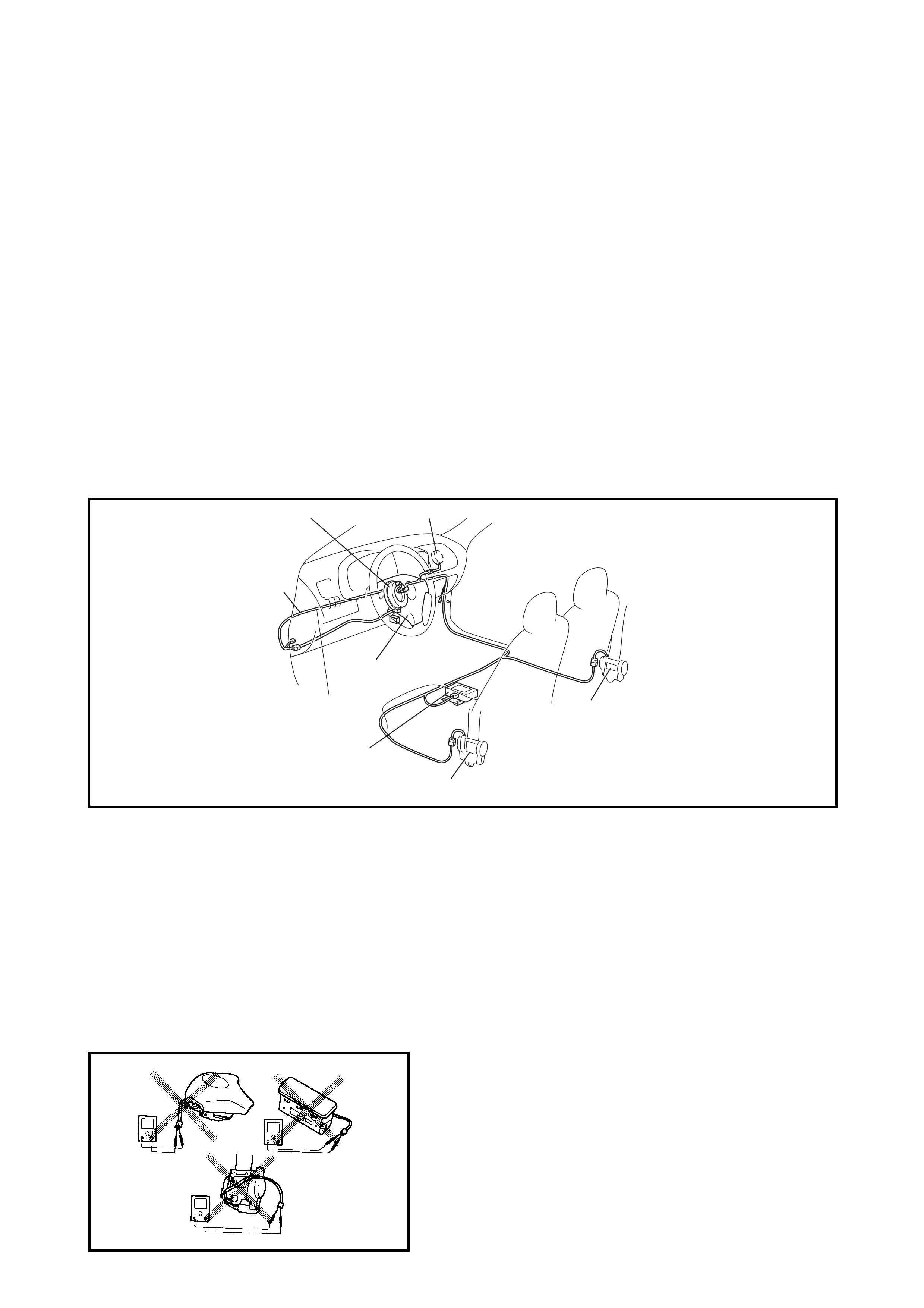
• The configuration of airbag system parts are as shown in the figure. When it is necessary to ser-
vice (remove, reinstall and inspect) these parts, follow the procedures described in Section 10B.
Failure to follow proper procedures could result in possible airbag system activation, personal
injury, damage to parts or the airbag system being unable to activate when necessary.
• If the airbag system and another system within the vehicle both need repair, the airbag system
should be repaired first to avoid unintended airbag system activation.
• Do not modify the steering wheel, dashboard, or any other airbag system components.
Modifications can adversely affect airbag system performance and lead to injury.
• If the vehicle will be exposed to temperatures over 93°C (for example, during a paint baking
process), remove the airbag system components beforehand to avoid component damage or
unintended airbag system activation.
Legend
DIAGNOSIS
• When troubleshooting the airbag system, refer to
Section 10B, 2. DIAGNOSIS. Bypassing these
procedures may result in extended diagnostic time,
incorrect diagnosis, and incorrect parts replacement.
• Never use electrical test equipment other than that
specified.
WARNING: Never measu re the resistance of the ai rbag
(inflato r) modules (d river and passenger) an d seat belt
pretensioners (driver and passenger), as the electric
current from the tester may deploy the airbag or
activate the pretensioner.
3
4
4
6
1
52
1. Airbag wire harness 4. Seat belt pretensioner
2. Passenger airbag (inflator) module 5. Contact coil
3. SDM 6. Driver airbag (inflator) module
SERVICING AND HANDLING
WARNING – DRIVER AND PASSENGER AIRBAG MODULES:
Many service procedures require disconnection of the AIRBAG fuse and all airbag (inflator) modules
from the initiator circuit to avoid an accidental deployment.
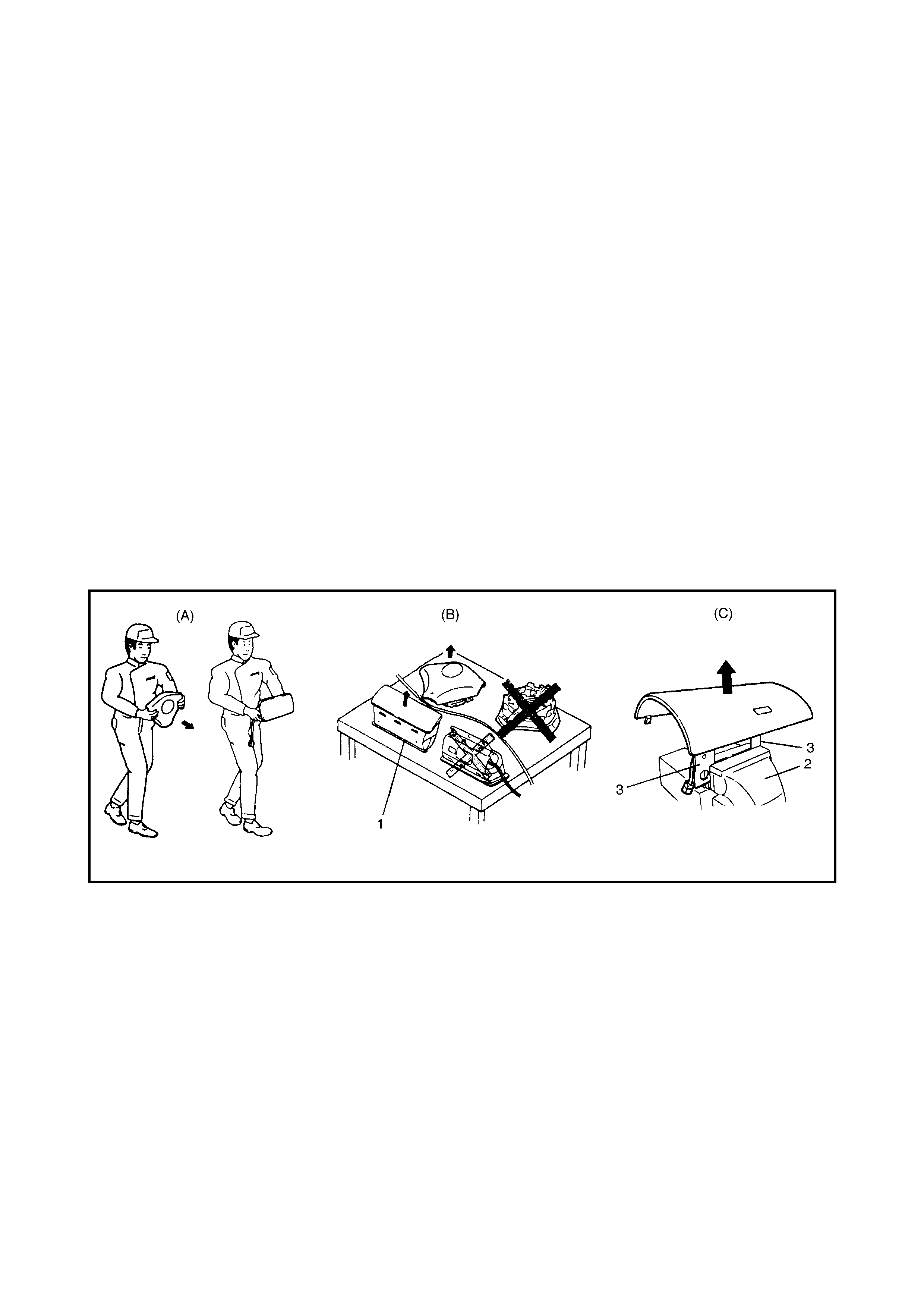
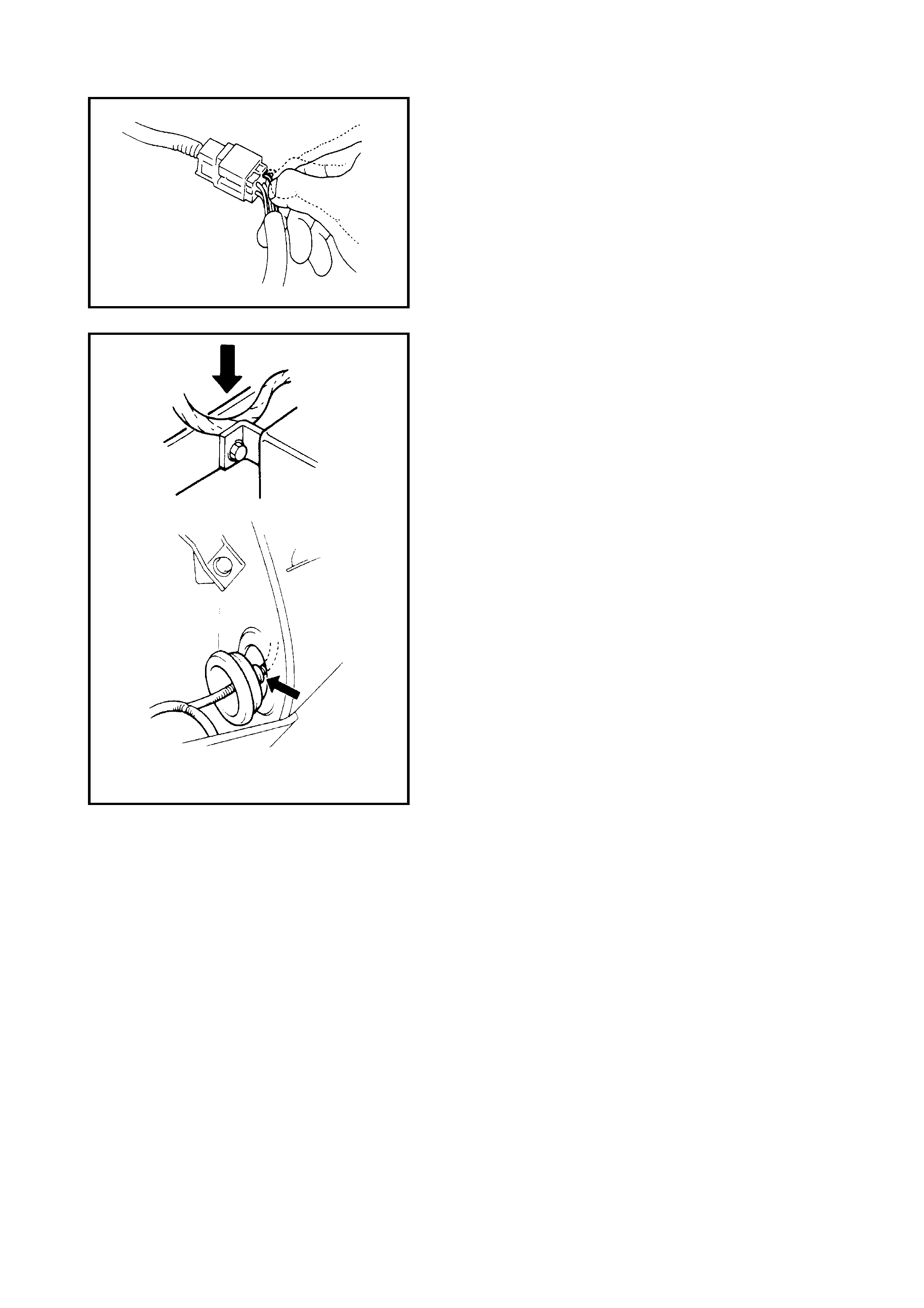
• For the handling and storage of a live airbag (inflator) module, select a place where the ambient
temperature is below 65°C, with low humidity and away from electric noise.
• When carrying a live airbag (inflator) module, make sure the airbag opening is pointed away from
you (A). In case of an accidental deployment, the airbag will then deploy with minimal chance of
injury.
• Never carry the airbag (inflator) module by the wires or connector on the underside of the module.
• When placing a live airbag (inflator) module on a bench or other surface, always face the airbag
up, away from the surface (B). As the live passenger airbag (inflator) module must be placed with
its bag (trim cover) facing up, place it on the workbench with a slit or use the workbench vise (2) to
hold it securely at its lower mounting bracket (3). This is necessary so that a free space is
provided to allow the airbag to expand in the unlikely event of accidental deployment. Otherwise,
personal injury may result.
• Never dispose of live (undeployed) airbag (inflator) modules. If disposal is necessary, deploy them
according to the deployment procedures described in Section 10B before disposal.
• The airbag (inflator) module is very hot immediately after deployment. Wait for at least half an hour
for it to cool before proceeding the work.
• After an airbag (inflator) module has been deployed, the surface of the airbag may contain a
powdery residue. This powder consists primarily of cornstarch, used to lubricate the bag as it
inflates, and by-products of the chemical reaction. As with many service procedures, gloves and
safety glasses should be worn.
WARNING – SENSING AND DIAGNOSTIC MODULE (SDM):
• For handling and storage of a SDM, select a place where the ambient temperature is below 65°C,
with low humidity and away from electric noise.
• During service procedures, be very careful when handling a SDM. Never strike or jar the SDM.
• Never power-up the airbag system when the SDM is not rigidly attached to the vehicle. All SDM
and mounting bracket fasteners must be carefully torqued and the arro w must be pointing toward
the front of the vehicle to ensure proper operation of the airbag system. The SDM could be
activated when powered while not rigidly attached to the vehicle, which could cause deployment
and result in personal injury.
WARNING – DRIVER AND PASSENGER SEAT BELT PRETENSIONERS:
• For handling and storage of a live seat belt pretensioner, select a place where the ambient
temperature is below 65°C, with low humidity and away from electric noise.
• Never carry seat belt pretensioner by the wire or connector of the pretensioner.
• When placing a live seat belt pretensioner on a workbench or similar, do not place anything
else on top of it.
• Never dispose of a live (unactivated) seat belt pretensioner. If disposal is necessary, activate
the pretensioner according to activation procedures described in Section 10B before disposal.

• The seat belt pretensioner is very hot immediately after activation. Wait for at least half an hour
for it to cool before proceeding work.
• As with many service procedures, gloves and safety glasses should be worn to prevent any
possible irritation of the skin or eyes.
WARNING:
• If a collision was light enough not to cause airbags to activate, inspect system parts and other
related parts according to instructions under 3.2 REPAIR AND INSPECTION REQUIRED AFTER AN
ACCIDENT in Section 10B.
• When servicing parts other than airbag system, if shocks may be applied to airbag system
component parts, remove those parts beforehand.
• When handling the airbag (inflator) modules, seat belt pretensioners or SDM, be careful not to
drop or apply an impact to it. If an excessive impact was applied, never attempt disassembly or
repair but replace it with a new one.
• If grease, cleaning agent, oil, water, etc. gets onto an airbag (inflator) module or seat belt
pretensioner, wipe it off immediately with a dry cloth.
• The airbag wire harness can be identified easily as it is covered with a yellow protection tube. Be
very careful when handling it.
• When an open in airbag wire harness, damaged wire harness, connector or terminal is found,
replace the wire harness, connectors and terminals as an assembly.
• Do not apply power to the airbag system unless all components are connected or a diagnostic
chart requests it, as this will set a diagnostic trouble code.
• Never use airbag system components from another vehicle.
• When electric welding, temporarily disable the airbag system, refer to
3.1 SERVICE PRECAUTIONS in Section 10B.
• Never expose the airbag system component parts directly to hot air (drying or baking the vehicle
after painting) or flames.
• WARNING/CAUTION labels are attached on each part of airbag system components. Follow the
instructions.
• After the vehicle is completely repaired, perform 2.4 AIRBAG DIAGNOSTIC SYSTEM CHECK in
Section 10B.
1.2 GENERAL PRECAUTIONS
The warnings and cautions below describe some of the general precautions that you should observe when
servicing a vehicle. These general precautions apply to many of the service procedures described in this
service information and will not necessarily be repeated with each procedure to which they apply.
WARNING:
• Whenever raising a vehicle for service, follow the instructions under 4. VEHICLE LIFTING POINTS
in this Section.
• When service work is required while the engine running, ensure the park ing brake is fully ON and
the transmission is in Neutral (manual transmission) or Park (automatic transmission). Keep
hands, hair, clothing, tools, etc. away from the fan and belts when the engine is running.
• When it is necessary to run the engine indoors, make sure that the exhaust gas is forced
outdoors.
• Do not perf orm service w ork in area s wh e re comb ust ible mat er ials can co me in contact wi th a hot
exhaust system.
• When working with toxic or flammable materials (such as gasoline and refrigerant), make sure that
the area the work is well-ventilated.
• To avoid burns, keep away from hot metal parts such as the radiator, exhaust manifold, tail pipe,
muffler, etc.
• New and used engine oil can be hazardous. Do not swallow oil or allow continuous contact with
the skin. Continuous contact with used engine oil has been found to cause [skin] cancer in
laborato ry animals. Brief contact with used oil may irr itate skin. To minimise your exposure, wear
a long-sleeve shirt and moisture-proof gloves when changing engine oil. If engine oil contacts
your skin, wash thoroughly with soap and water. Launder any clothing or rags if wet with oil.
• Keep oil filters away from children and pets. Recycle or properly dispose of used oil and filters
• Make sure the bonnet is fully closed and latched before driving. If it is not, it can open
unexpectedly during driving, obstructing your view and resulting in a collision.
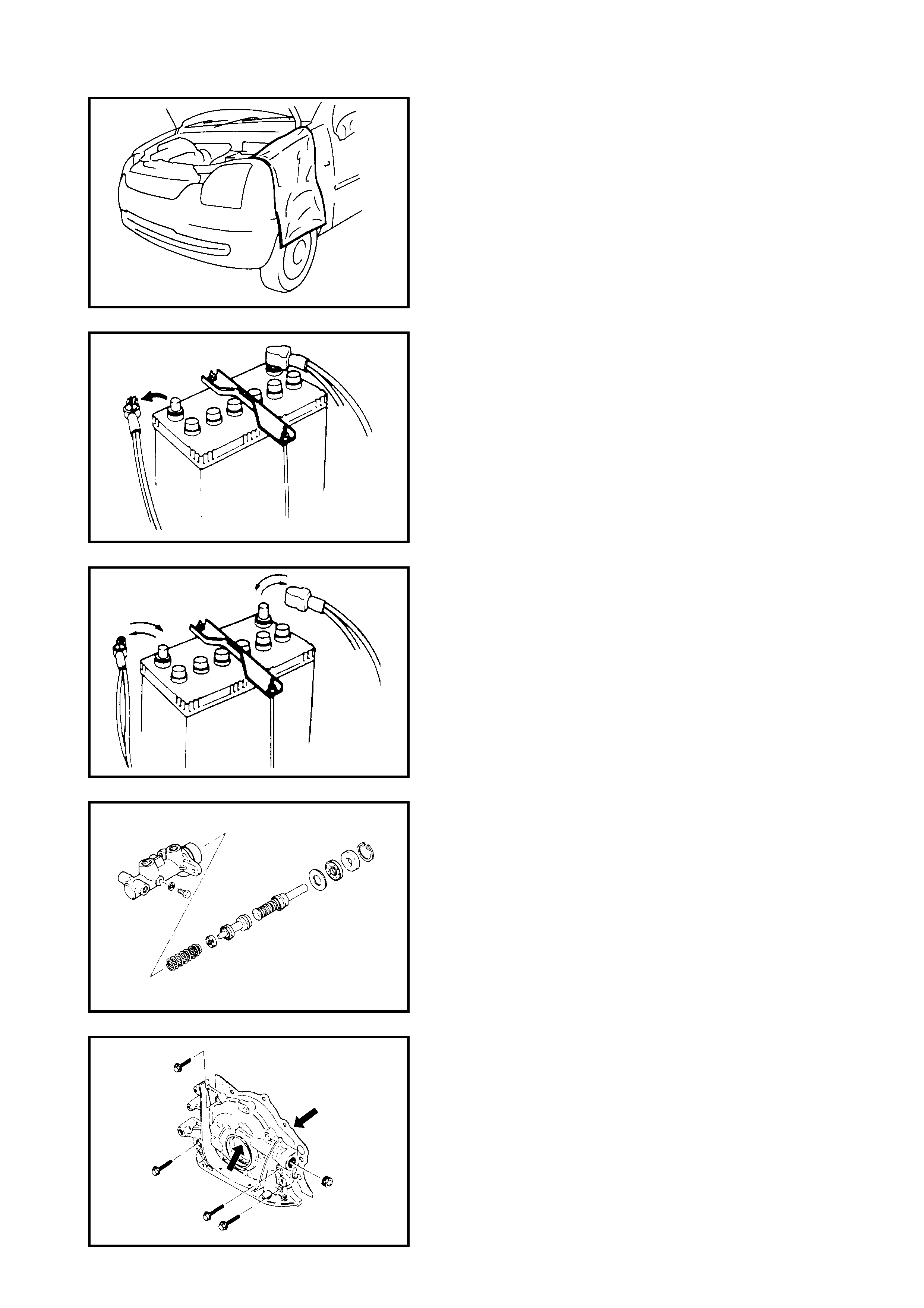
• Before beginning any service work, cover the fenders,
seats and any other parts that are likely to get
scratched or stained during servicing. Also be aware
that what you wear (e.g. buttons) may cause damage
to the vehicle’s finish.
• When performing service of electrical parts that does
not require use of battery power, disconnect the
negative cable of the battery.
IMPORTANT: Whenever the battery is disconnected,
the audio unit is disabled and will require a personal
identification number (PIN) code to be entered for the
audio unit to be reinstated, refer to Section 8B,
2.1 AUDIO UNIT PIN CODE.
• When removing the battery, disconnect the negative
cable first and then the positive cable. When
reconnecting the battery, connect the positive cable
first and then the negative cable, and replace the
terminal cover.
• When removi ng parts that are to be re used, ke ep the m
arranged in an orderly manner so that they may be
reinstalled in the proper order and position.
• Whenever you use oil seals, gaskets, packing, O-rings,
locking washers, split pins, self-locking nuts, and
certain other parts as specified, replace with new ones.
Also, before installing new gaskets, packing, etc.,
remove any residual material from the mating surfaces.
• Make sure that all parts used in reassembly are
perfectly clean.
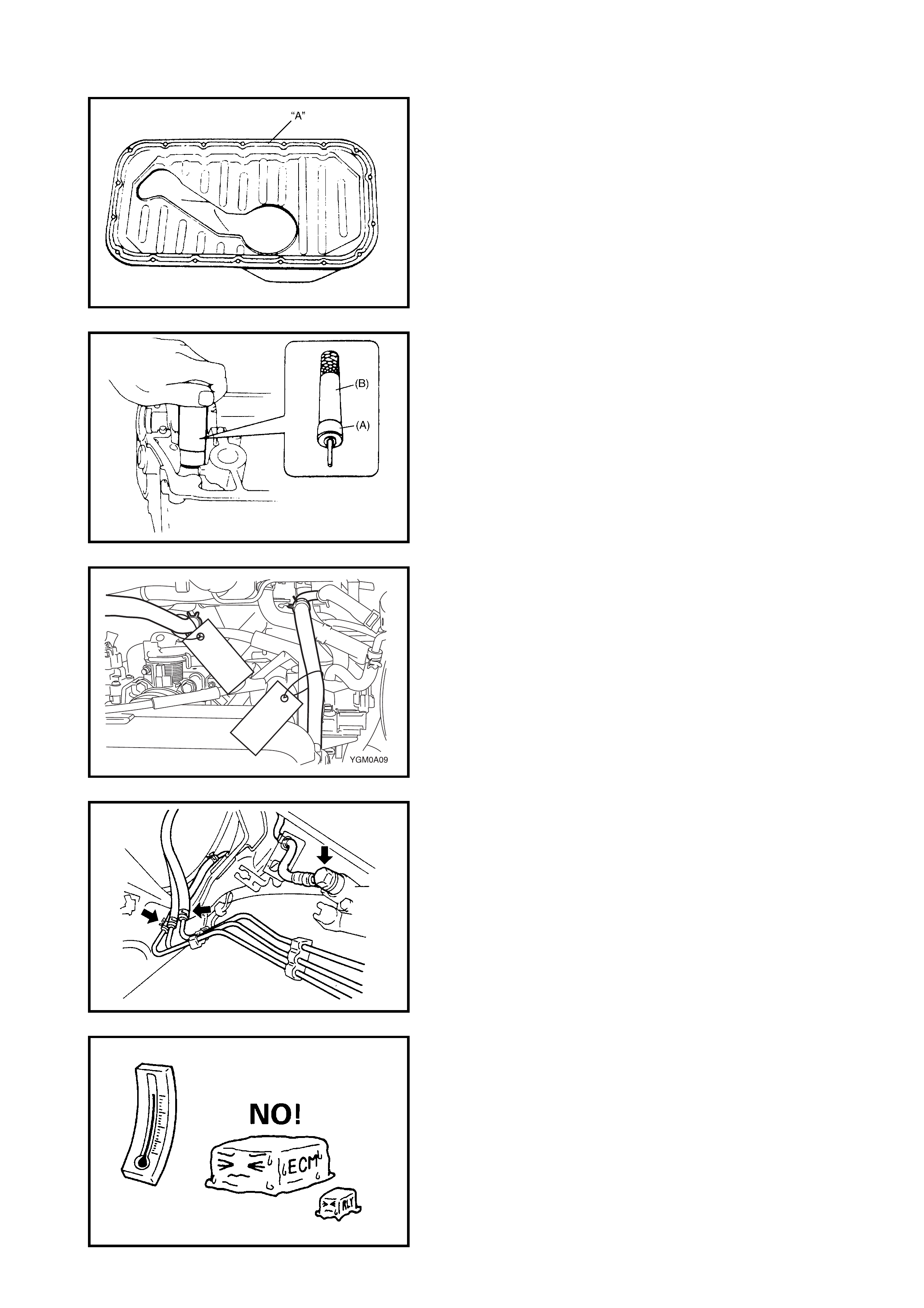
When use of a certain type of lubricant, bond or sealant
is specified, be sure to use the specified type,
e.g. (A ): Seala nt Three Bond No . 1207C
• Be sure to use special tools when instructed,
e.g. special tool (A) 09917-98221 (A) and
(B) 09916-58210 (B).
• When disconnecting vacuum hoses, attach a tag
describing the correct installation positions so that the
hoses can be reinstalled correctly.
• After servicing fuel, oil, coolant, vacuum, exhaust or
brake systems, check all lines related to the system for
leaks.
• For vehicles equipped with fuel injection systems,
never disconnect the fuel line between the fuel pump
and inje ctor witho ut firs t relea sing the f uel p ressure, or
fuel can be sprayed out under pressure.
• When performing a work that produces a heat
exceeding 80°C in the vicinity of the electrical parts,
remove the heat sensitive electrical part(s) beforehand.
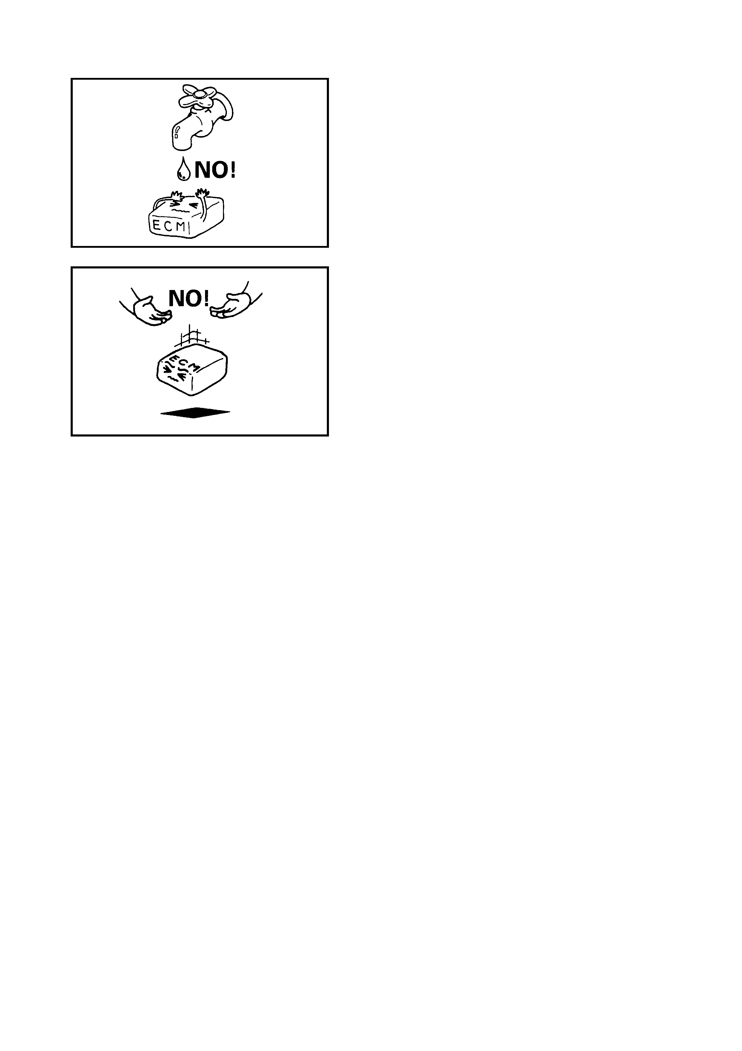
• Use care no t to expose c onnec tors and el ectric al parts
to water.
• Always be carefu l not to handle elec tr ical parts (ECMs ,
relays, etc.) in a rough manner or drop them.
1.3 PRECAUTIONS FOR CATALYTIC CONVERTER
Use only unleaded fuel and ensure unburned fuel does not enter the catalytic converter as it can be damaged.
• Conduct a spark jump test only when necessary, make it as short as possible, and do not open the
throttle.
• Conduct engine compression checks within the shortest possible time.
• Avoid situations which can result in engine misfire (e.g. starting the engine when the fuel tank is nearly
empty.)
1.4 PRECAUTIONS FOR INSTALLING MOBILE COMMUNICATION EQUIPMENT
When in stalling mobi le com munication equipme nt s uch as C B radi o or cellula r-te lep hon e, ob ser v e the foll ow-
ing precautions. Failure to follow cautions may adversely affect electronic control system.
• Keep the antenna as far away as possible from the vehicle’s electronic control module (ECM).
• Keep the antenna feeder more than 20 cm away from the electronic control module and its wire har-
nesses.
• Do not run the antenna feeder parallel with other wire harnesses.
• Confirm that the antenna and feeder are correctly adjusted.
1.5 PRECAUTION IN SERVICING FULL-TIME 4WD VEHICLES
This full-time 4WD vehicle can not be converted to 2WD.
Observe the following cautions when servicing otherwise drivetrain damage and personal injury may result.
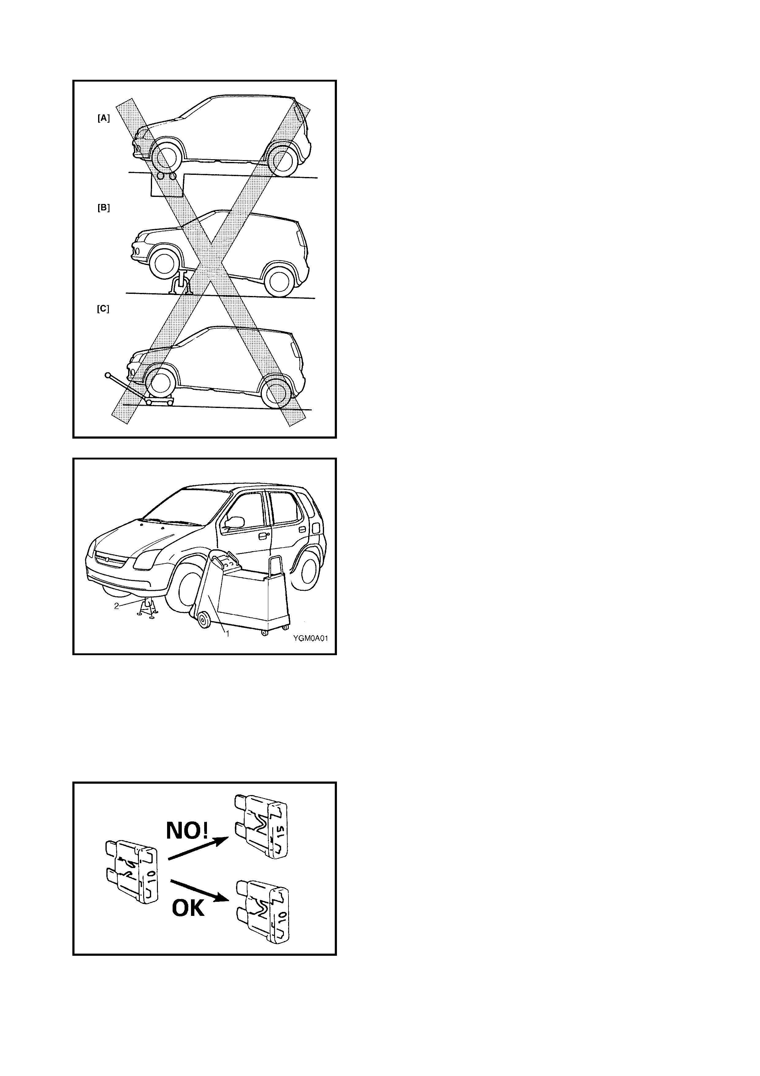
• Never perform any of the following types of service
work:
[A]: Testing with 2-wheel chassis dynamometer, speed-
ometer tester or brake tester.
[B]: Driving front wheels which are jacked up.
[C]: Towing under the condition where either front or
rear wheels can not rotate.
• If testing with 2-wheel chassis dynamometer, speed-
ometer tester or brake tester is required, make the
vehicle front wheel drive by removing the propeller
shaft.
• When using on-vehicle type wheel balancing equip-
ment (1), jack up all four wheels off the ground com-
pletely and support vehicle with safety stands (2).
Be careful of the other wheels, which will rotate at the
same time.
• This vehicle must only be towed under one of the fol-
lowing conditions:
•With all wheels on a flatbed truck, or
•With the front or rear wheels lifted and a dolly under
the other wheels.
1.6 PRECAUTIONS FOR ELECTRICAL CIRCUIT SERVICE
• When replacing a fuse, only use a fuse of the specified
capacity. Use of a fuse with a larger capacity will cause
a damage to the electrical parts and a fire.
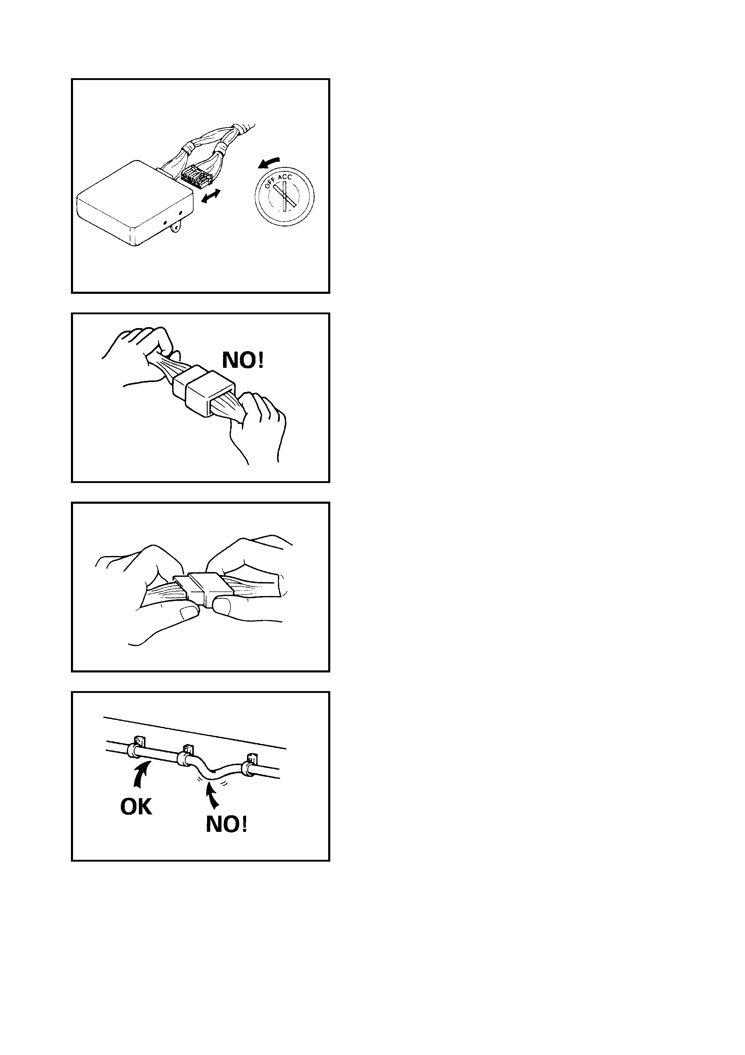
• When disconnecting and connecting connectors, turn
ignition switch OFF or electronic parts may get dam-
aged.
• When disconnecting connectors, never pull the wiring
harness. Unlock the connector lock first and then pull
them apart by holding the connectors themselves.
• When connecting connectors, also hold connectors
and push them together until they lock securely (a click
is heard).
• When installing the wiring harness, fix it with clamps so
that no slack is left.
• When in stalling vehic le parts, take care not to int erfere
with wiring harness or any other part.
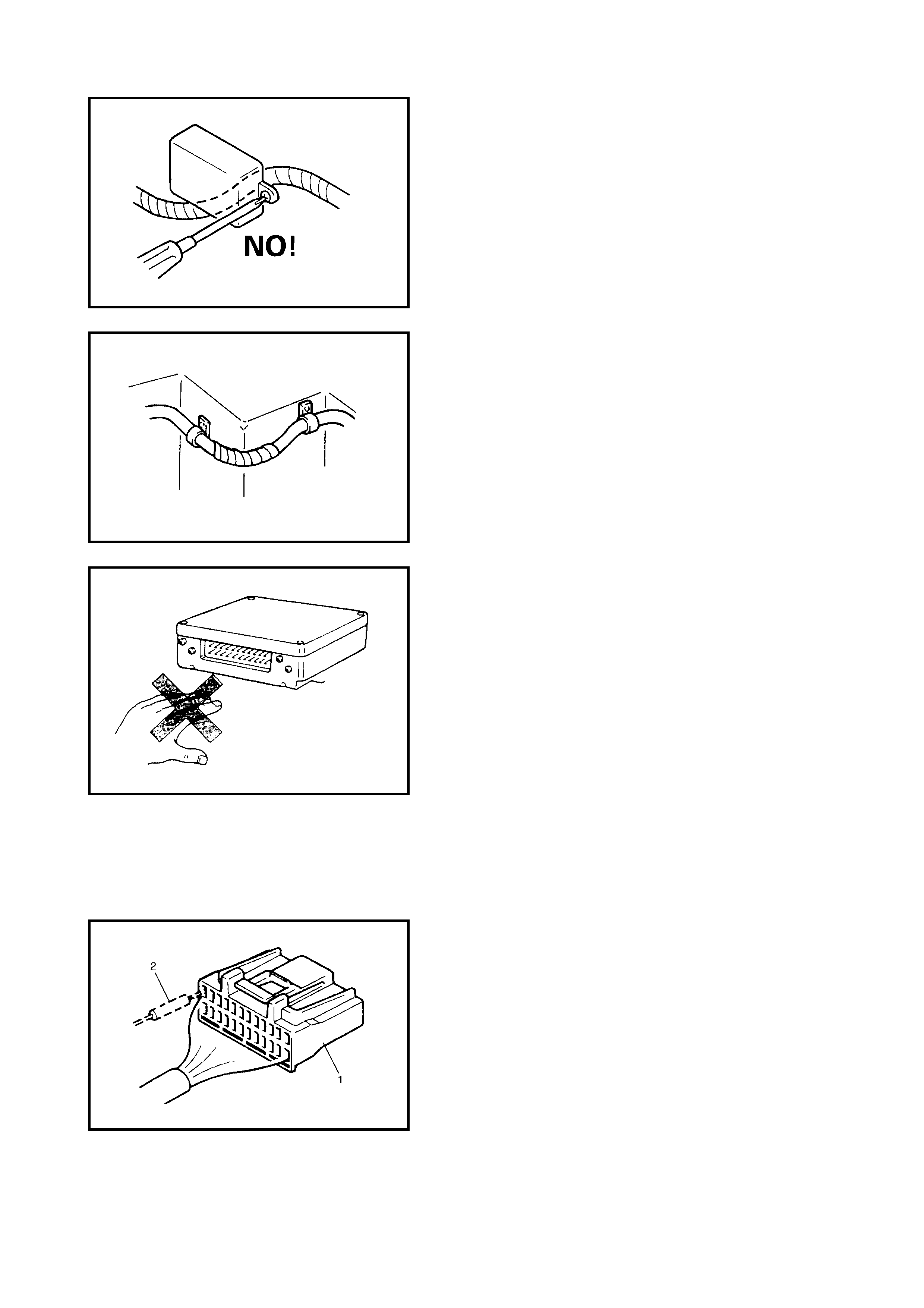
• To avoid damage to the harness, protect it from contact
against a part forming a sharp angle by winding tape or
the like aroun d it.
• Do not touch the electrica l termi nals of parts whic h use
microcomp uters (e.g. E CM, PCM, P/S controller, etc .).
The static electricity from your body can damage these
parts.
• Never connect a tester (voltmeter, ohmmeter, etc.) to
an electroni c contro l module whe n its connector i s dis-
connected as it may cause damage.
• Never con nect an ohmme ter to ele ctronic contr ol mod-
ule with its connec tor connecte d as it may caus e dam-
age to the electronic control module and sensors.
• Only use a spe cifie d voltme ter/oh mmeter to te st cir cuit
otherwise accurate measurements may not be
obtained or personal i njury may r esult. If no t specifie d,
use a voltmeter with high impedance (M Ω/V minimum)
or a digital type voltmeter.
• When taking measurements at electrical connectors
using a te ster probe, insert th e probe (2) fr om the wire
harness side (backside) of the connector (1).
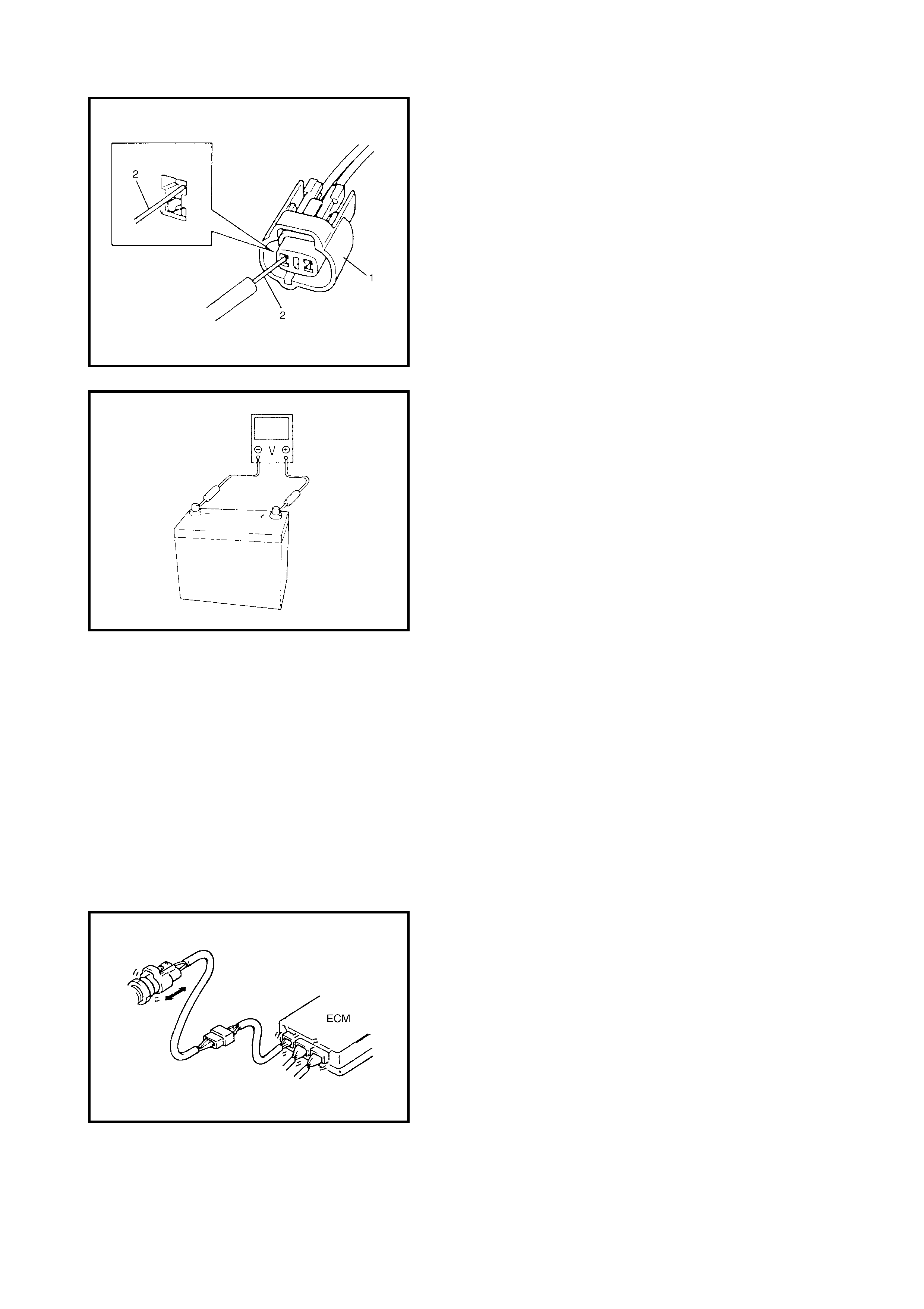
• When con necting a me ter probe ( 2) from term inal side
of connector (1) because it can’t be connected from
harness side, use e xtra care not to bend the m ale ter-
minal or force its female terminal open.
In case of such connector as shown, connect the probe
as shown to avoid opening female terminal.
• When checking connection of terminals, check its male
half for bends and the female half for excessive open-
ing and both for locking (looseness), corrosion, dust,
etc.
• Before measuring voltage at each terminal, check to
make sure that battery voltage is 11 V or higher. Such
terminal voltage check at low battery voltage will lead
to erroneous diagnosis.
1.7 ELEC TRICAL CIRCUIT INSPECTION PROCEDURE
While there are various electrical circuit inspection meth-
ods, de scribed here i s a general metho d to check for ope n
and short circuit by using an ohmmeter and a voltmeter.
OPEN CIRCUIT CHECK
Possible causes for an open circuit are as follows. As the
cause is in the connector or terminal in many cases, they
need to be checked carefully.
• Loose co nne ction of conn ec tor.
• Poor contact of terminal (due to dirt, corrosion, poor
contact tension, entry of foreign object etc.).
• Wire harness being open.
When checking system circuits, including an electronic
control module such as the ECM, TCM, ABS con trol mod-
ule, etc., start with items which are easier to check.
1. Disconnect negative (–) cable from battery
2. Check ea ch co nne cto r at both en ds of the ci rcui t b ein g
checked for loose connection. Also check lock
conditio n of th e co nnector if equ ip ped wi th a con nec tor
lock.
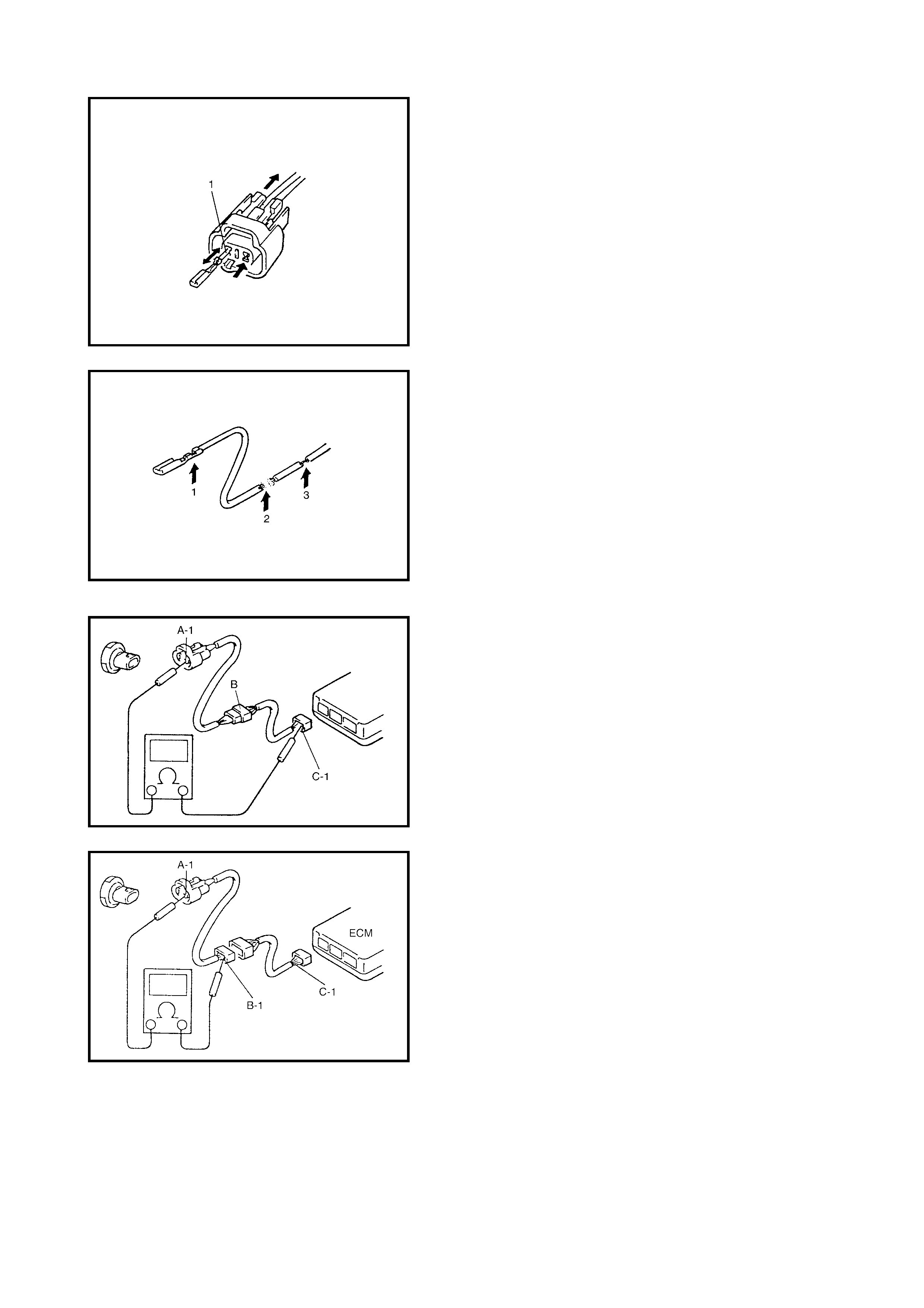
3. Using a male tes t termina l (1), chec k both t erminal s of
the circuit being checked for contact tension of its
female terminal.
Check eac h termina l visual ly for poo r contact (p ossibly
caused by dirt, corrosion, entry of foreign object, etc.).
At the same time, check to make sure that each
terminal is locked in the connector fully.
4. Using continuity check or voltage check as described
in the following procedure, check the wire harness for
looseness of crimping (1), open circuit (2), thin
(broken) strands of wire (3) and poor connection with
its terminals. Locate abnormality, if any.
CONTINUITY CHECK
1. Measure the resistance between connector terminals
at both end s of the c ircui t be in g c hec ked (b etwe en A- 1
and C-1 a s sh own). If no c ont inu ity i s ind icate d ( infi nity
or over limit) , the cir cuit is op en betwee n termina ls A-1
and C-1.
2. Disconnect the connector included in the circuit (con-
nector-B) and measure resistance between terminals
A-1 and B-1.
If no cont inu ity is ind icate d, the ci rcui t is ope n b etwee n
terminals A-1 and B-1. If continuity is indicated, there is
an open circuit between terminals B-1 and C-1 or an
abnormality in connector B.
VOLTAGE CHECK
If voltage is sup pl ied to the ci rcui t bei ng chec k ed, a vo ltage
check can be used as a circuit check.
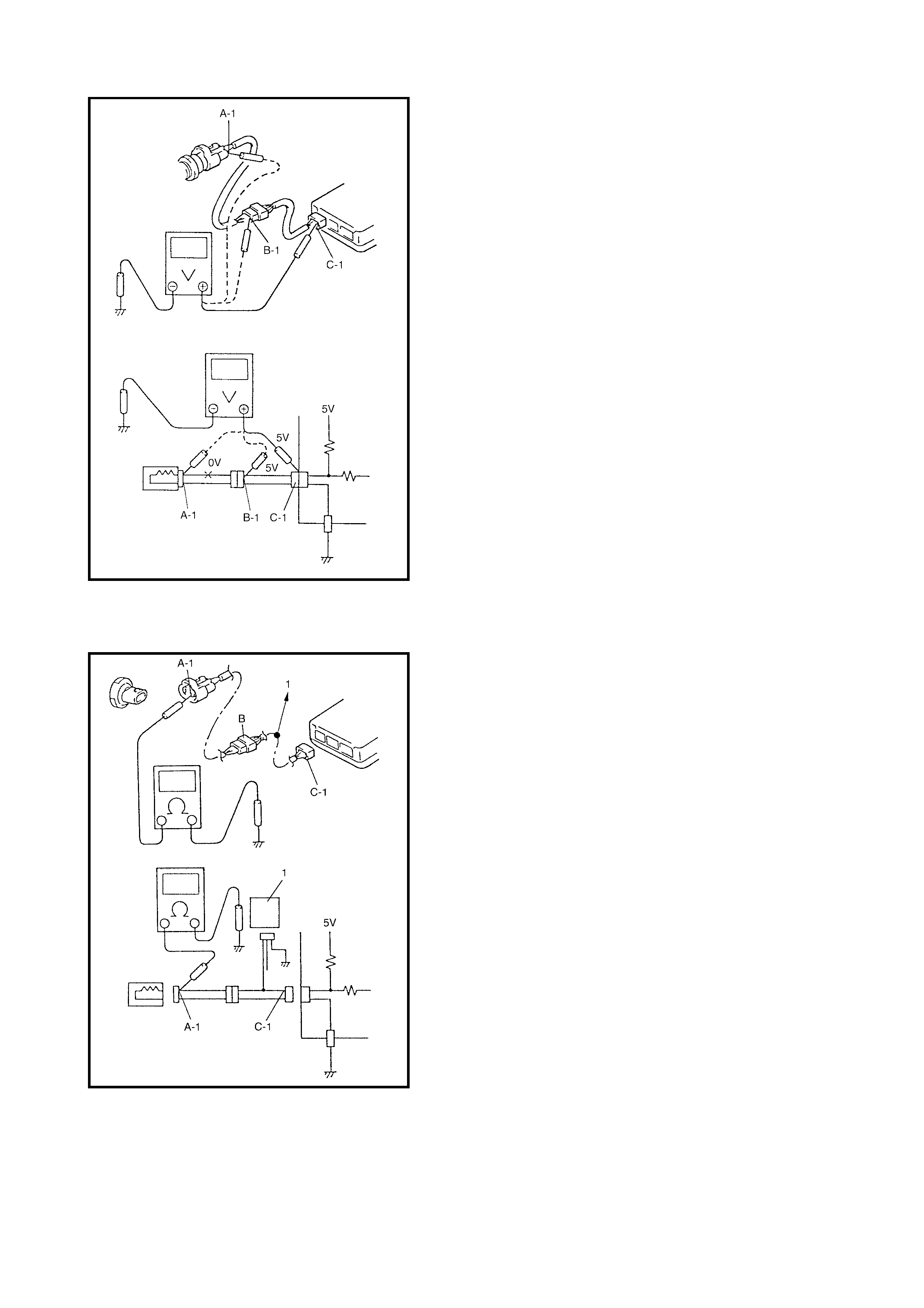
1. With all connectors connected and voltage applied to
the circuit being checked, measure the voltage
between each terminal and body ground.
a. If measurements were taken as shown and the
results were as listed below, the circuit is open
between terminals B-1 and A-1.
Voltage between
C-1 and body ground: Approx. 5 V
B-1 and body ground: Approx. 5 V
A-1 and body ground: 0 V
b. If the mea sured values were as listed below, there
is a resistance (abnormality) of such a level which
corresponds to the voltage drop in the circuit
between terminals A-1 and B-1.
Voltage between
C-1 and body ground: Approx. 5 V
B-1 and body ground: Approx. 5 V
A-1 and body ground: Approx. 3 V
SHORT CIRCUIT CHECK (WIRE HARNESS TO
GROUND)
1. Disconnect negative (–) cable at battery.
2. Disconnect the connectors at both ends of the circuit to
be checked.
NOTE: If the circuit to be checked is connected to other
parts (1), disconnect all connectors of those parts.
Otherwise, diagnosis will be miss-led.
3. Measure the resistance between the terminal at one
end of circuit (A-1 terminal) and body ground. If conti-
nuity is indicated, there is a short to ground between
terminals A-1 and C-1 of the circuit.
4. Disconnect the connector included in the circuit (con-
nector B) and measure resistance between A-1 and
body ground.
If continuity is indicated, the circuit is shorted to the
ground between terminals A-1 and B-1.
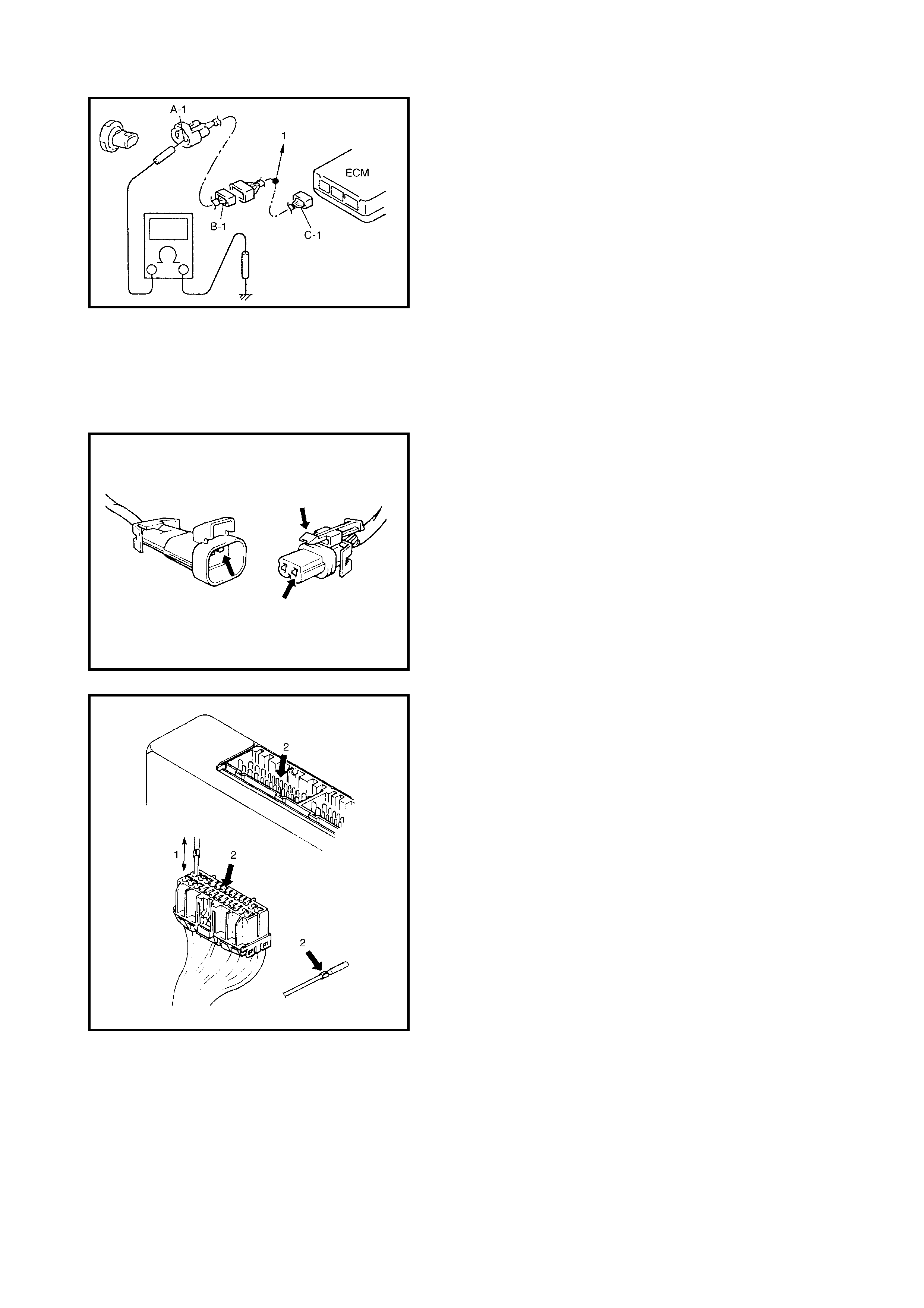
INTERMITTENTS AND POOR CONNECTIONS
Most intermittents are caused by faulty electrical connec-
tions or wiring, although a sticking relay or solenoid can
occas ionally be at fault. Whe n ch ecking for prope r connec-
tion, perform careful checks of suspect circuits for:
• Poor ma ting of conn ector halves, o r terminals no t fully
seated in the connector body (backed out).
• Dirt or corrosion on the terminals. The terminals must
be clean and free of any foreign material which could
impede proper terminal contact. Cleaning the terminal
with a sand paper or the like is prohibited.
• Damaged connector body, exposing the terminals to
moisture a nd dirt as we ll a s not ma inta ining pr op er te r-
minal orientation with the component or mating con-
nector.
• Improperly formed or damaged terminals.
Check each connector terminal in problem circuits
carefully to ensure good contact tension (1) by using
the correspo ndi ng mati ng termi nal .
If contact tension is not enough, reform it to increase
contact tension or replace.
Also check for bent terminals and poor alignment (2).
• Poor t erminal-to-wire connection.
Check each wire harness in problem circuits for
poor connection by shaking it by hand lightly. If any
abnormal condition is found, repair or replace.
• Wire insulation which is rubbed through can cause an
intermit tent sh ort as the bare ar ea touc he s othe r wirin g
or parts of the vehicle.
• Wiring broken inside the insulation could cause conti-
nuity check to show a good circuit, but if only 1 or 2
strands o f a m u lt i-s tra nd-ty pe wi r e a re i ntact, the re sis-
tance could be far too high.
If any abnormality is found, repair or replace.
2. IDENTIFICATION INFORMATION & PLATES
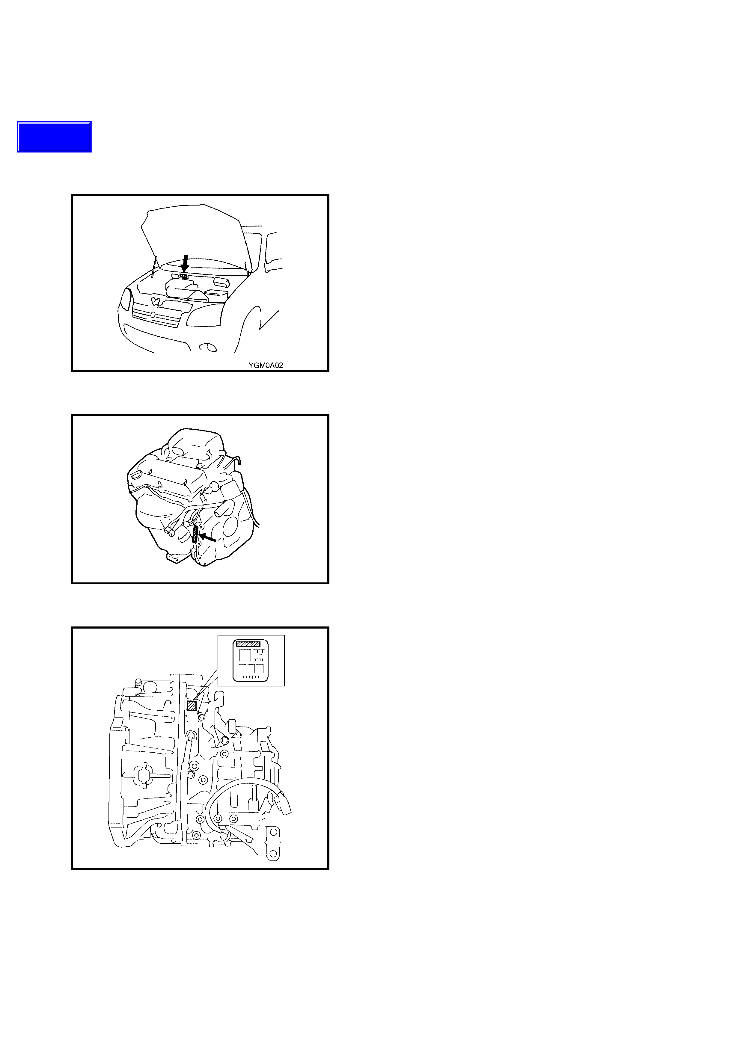
2.1 VEHICLE IDEN TIFICATION NUMBER
The vehicle identification number is stamped on the front
dash panel in the engine compartment.
2.2 ENGINE IDENTIFICATION NUMBER
The engine number is stamped on the cylinder block.
2.3 TRANSMISSION IDENTIFICATION NUMBER
The automatic transmission identification number is located
on transmission case.
Techline
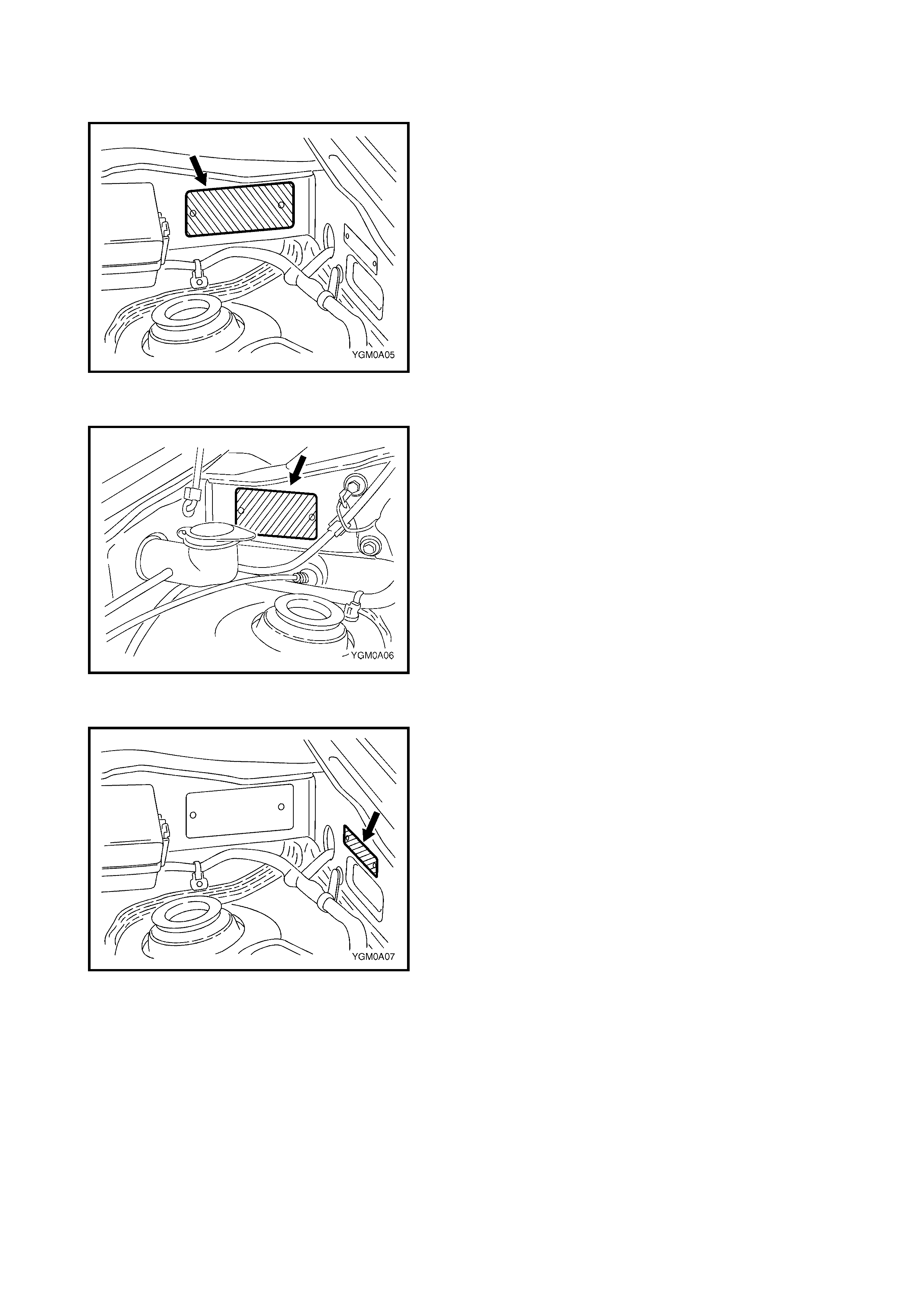
2.4 SAFETY COMPLIA NCE PLATE
The s afety com pliance pl ate is a ffixed to th e left-hand side
of the dash panel in the engine compartment with rivets
and is stamped with the following information:
• Compliance plate approval number,
• Vehicle category code,
• Name appearing on compliance plate approval,
• Make and model,
• Seating capacity,
• Date of manufactur e,
• Vehicle identification number (VIN).
2.5 BODY & OPTION IDENTIFICATION PLATE
The body and option identification plate is affixed to the
right-hand side of the dash panel in the engine compart-
ment with riv ets and is stamped with the followin g informa-
tion:
• Body Type,
• Vehicle identification number (VIN),
• Engine model,
• Paint / Trim number,
• Date of manufactur e.
2.6 TAG PLATE
The tag plate is affixed to the left-hand inner fender panel in
the engine compartment with rivets and is stamped with
vehicle body information.

3. WARNING, CAUTION AND INFORMATION LABELS
The figure below shows the main labels that are attached to vehicle component parts.
When servicing and handling parts, refer to W ARNING/CAUTION instructions printed on labels.
If any WARNING/CAUTION label is found stained or damaged, clean or replace it as necessary.
Legend
Legend
1. Airbag label on back side of engine hood 4. Engine cooling fan label
2. Airbag label on sun visor 5. Steering shaft joint cover label
3. Radiator cap label
1. Airbag label on driver airbag (inflator) module 4. Airbag label on SDM
2. Airbag label on combination switch and contact coil 5. Pretensioner label on seat belt retractor
3. Airbag label on passenger airbag (inflator) module 6. Child seat label

4. VEHICLE LIFTING POINTS
USING A HOIST
WARNING:
• Before hoisting the vehicle, consider the vehicle balance during the service operations being
performaed. The balance while on the hoist may change depending on the parts to be removed.
• Before lifting the vehicle, check that each end of the hoist arms are not in contact with brake
pipes, fuel pipes, brackets or any other part.
• Locate the hoist pads as shown. Lift up the vehicle until the tyres are slightly off the ground and
make sure that the vehicle will not fall by moving vehicle body both ways. Work can be started
only after this confirmation.
• Make absolutely sure to lock the hoist after vehicle is raised.
Legend
1. Veh icle fr ont 3. Floo r jack positio n
2. Support position for hoist pads and safety stand 4. Embossed-mark
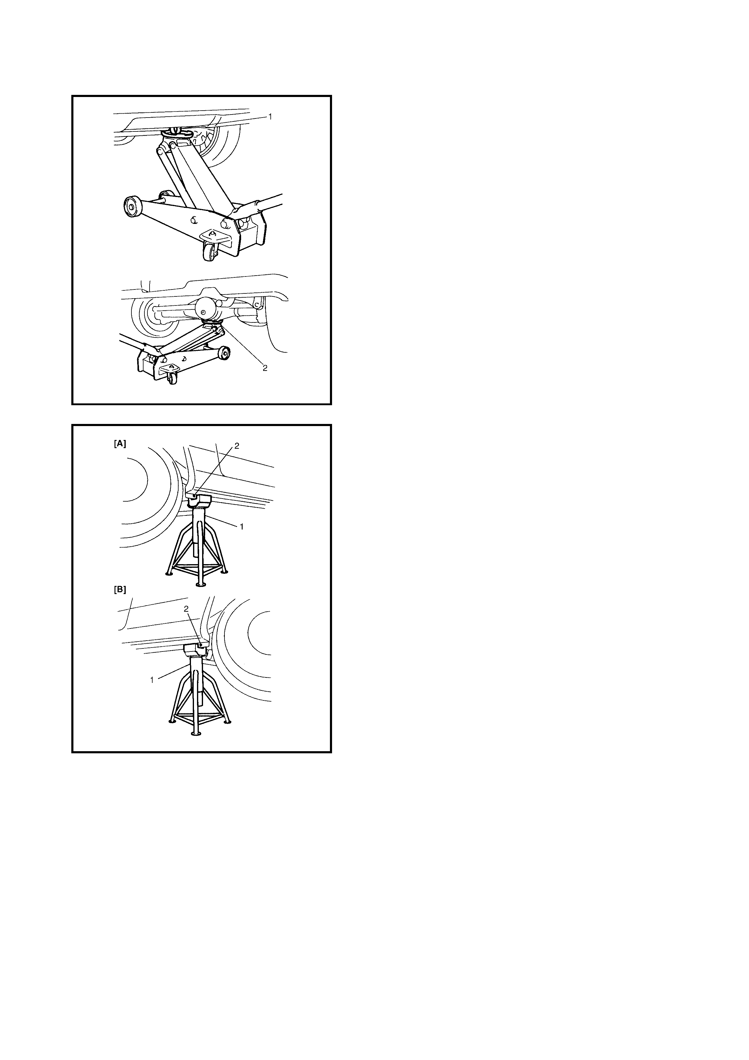
USING A FLOOR JACK
WARNING: If the vehicle is to be jacked-up only at the
front or rea r end, block the wheels on grou nd to ensure
safety.
Aft er the v ehicle is jacked-up, suppor t it on stands. It is
extremely dangerous to do any work on the vehicle
raised on a jack alone.
CAUTION: Never place the jack against suspension
parts (i.e. stabiliser, etc.) or vehicle floor.
When ra ising fron t or rear o f the vehicl e off the floor with a
jack, loc at e the jac k agains t the fr ont ja ck in g bra cket ( 1), or
the rear axle housing (2).
When per forming serv ice with the vehic le jacked up, pl ace
safety stands (1) under the vehicle body at [A] the front or
[B] the r ear at the embo ss ed mar k ( 2), so tha t it is s ec urely
suppor ted. Check t o ensur e that the vehicle does not slide
on the safety stands and the vehicle is held stable.

5. ABBREVIATIONS AND SYMBOL S USED IN THIS MANUAL
ABBREVIATIONS
A
ABS Anti-lock Brake System
E
EFE Heater Early Fuel Evaporation Heater
(Positive T emperature Coefficient,
PTC Heater)
ATDC After Top Dead Centre
API American Petroleum Institute
ATF Automatic Transmission Fluid EPS Electronic Power Steering
ALR Automatic Locking Retractor EVAP Evaporative Emission
AC Alternating Current EVAP Canister Evaporative Emission Canister
(Charcoal Canister)
A/T Automatic Transmission
F
4WD 4 Wheel Drive
A/C Air Conditioni ng
G
GEN Generator
ABDC After Bottom Dead Centre GND Ground
A/F Air Fuel Mixture Ratio
H
HC Hydrocarbons
A-ELR Automatic-Emergency Locking
Retractor HO2S Heated Oxygen Sensor
I
IAC Valve Idle Air Control Valve (Idle Speed
Control Solenoid Valve ISC
Solenoid Valve)
B
B+ Battery Positive Voltage
BTDC Before Top Dead Centre
BBDC Before Bottom Dead Centre IAT Sensor Intake Air Temperature Sensor
(Air temperature Sensor, ATS)
C
CKT Circuit
CKP sensor Crankshaft Position Sensor ICM Immobiliser Control Module
CMP sensor Camshaft Position Sensor IG Ignition
CO Carbon Monoxide ISC Actuator Idle Speed Control Actuator
CPP switch Clutch Pedal Position Switch
(Clutch Switch, Clutch Start
Switch)
L
LH Left Hand
LSPV Load Sen sing Prop or tio nin g
Valve
CPU Central Processing Unit
M
MAF Sensor Mass Air Flow Sensor (Air Flow
Sensor, AFS, Air Flow Meter,
AFM)
CRS Child Res traint System
D
DC Direct Current
DLC Data Link Connector (Assembly
Line Diag. Link, ALDL, Serial Data
Link, SDL)
MAP Sensor Manifold Absolute Pressure
Sensor (Pressure Sensor, PS)
Max Maximum
DOHC Double Over Head Camshaft MFI Multiport Fuel Injection
(Multipoi nt Fu el Injec tio n)
DOJ Double Offset Joint
DRL Daytime Running Light MIN Minimum
DTC Diagnostic Trouble Code MIL Malfunction Indicator Lamp
E
EBCM Electronic Brake Control Module,
ABS Control Module M/T Manual Transmis si on
EBD Electronic Brake Force
Distribution
N
NG No Good
ECM Engine Control Module NOx Nitrogen Oxides
ECT sensor Engine Coolant Temperature
Sensor (Water Temp. Sensor,
WTS)
O
OBD On-Board Diagnostic System
(Self-Diagnosis Function)
O/D Overdrive
EGR Exhaust Gas Recirculation OHC Over Head Camshaft
EGRT sensor EGR Temperature Sensor
(Recirculated Exhaust Gas Temp.
Sensor, REGTS)
O2S Oxygen Sensor
P
PNP Park/Neutral Position
P/S Power Steering

P
PSP Switch Power Steering Pressure Switch
(P/S Pres su re Switc h)
PCM P owe rt rain Cont ro l Modu le
PCV Positive Crankcase Ventilation
R
RH Right Hand
S
SAE Society of Automotive Engineers
SDM S en si ng and Diag nos ti c Mod ule
(Airbag control module)
SFI Sequential Multiport Fuel Injection
SOHC Single over Head Camshaft
T
TBI Throttle Body Fuel Injection
(Single-Point Fuel Injection, SPI)
TCC Torque Converter Clutch
TCM Tran sm ission Control Modu le
(A/T Control Module)
TP Sensor Throttle Position Sensor
TVV Thermal Vacuum Valve (Thermal
Vacuum Switching Valve, TVSV,
Bimetal Vacuum Switching Valve,
BVSV)
TWC Three Way Catalytic Converter
(Three Way Catalyst)
2WD 2 Wheel Drive
V
VIN Vehicle Identification Number
VSS Vehicle Speed Sensor
W
WU-OC Warm Up Oxidation Catalytic
Converter
WU-TWC Warm Up Three Way Catalytic
Converter
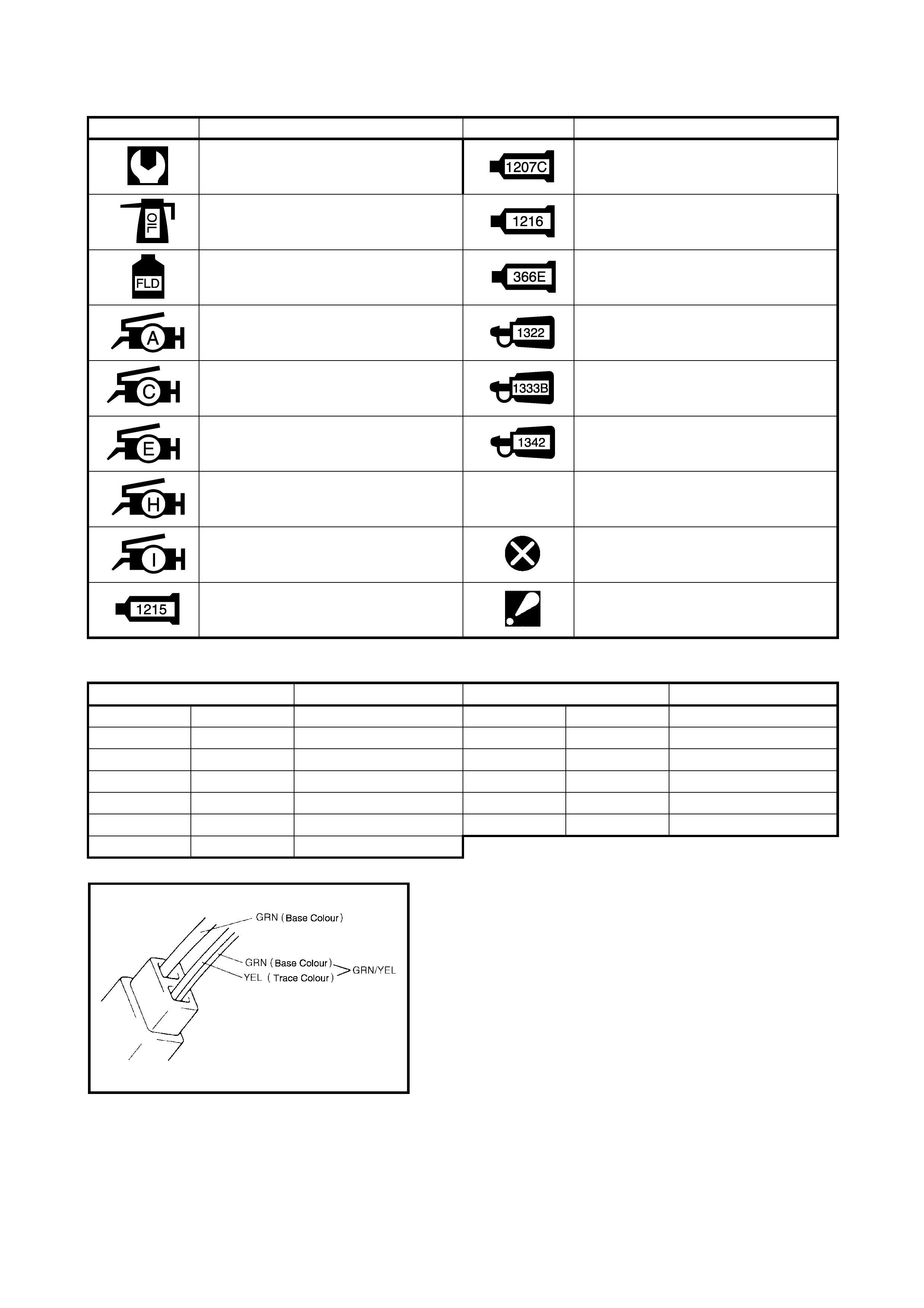
SYMBOLS
WIRE COLOUR SYMBOLS
There are two type of coloured wire used in this vehicle.
One is single-coloured wire and the other is dual-coloured
(traced) wire.
The si ngle-colour ed wire uses only on e colour symb ol (i.e.
GRN).
The dual-coloured wire uses two colour symbols (i.e. GRN/
YEL). The first symbol represents the base colour of the
wire (GRN in the figure) and the sec on d symbo l repr es ents
the colour of the trace (YEL in the figure).
SYMBOL DEFINITION SYMBOL DEFINITION
Tightening torque Apply Three Bond No. 1207C
Apply oil (engine, transmission,
transfer, differential) Apply Three Bond No. 1216B
Apply fluid (brake, power steering or
automatic transmission fluid) Apply Sealing Compound 366E
Lithium Grease Apply THREAD LOCK 1322
Lithium Grease Apply THREAD LOCK 1333B
Lithium Grease Apply THREAD LOCK 1342
Lithium Grease
Lithium Grease Do not reuse
Apply Three Bond No. 1215 Note on reassembly
Symbol Wire Colour Symbol Wire Colour
B BLK Black O, Or ORN Orange
BlBLUBlue RREDRed
Br BRN Brown W WHT White
GGRN Green Y YEL Yellow
Gr GRY Gray P PNK Pink
Lbl LT BLU Light blue V PPL Violet
Lg LT GRN Light green
6. FASTENER INFORMATION
6.1 METR IC FASTENERS
Most of th e fasten ers u sed for thi s vehic le are metri c. Whe n replac ing any fastener s, it is most impo rtant that
replacement fasteners be the correct diameter, thread pitch and strength.
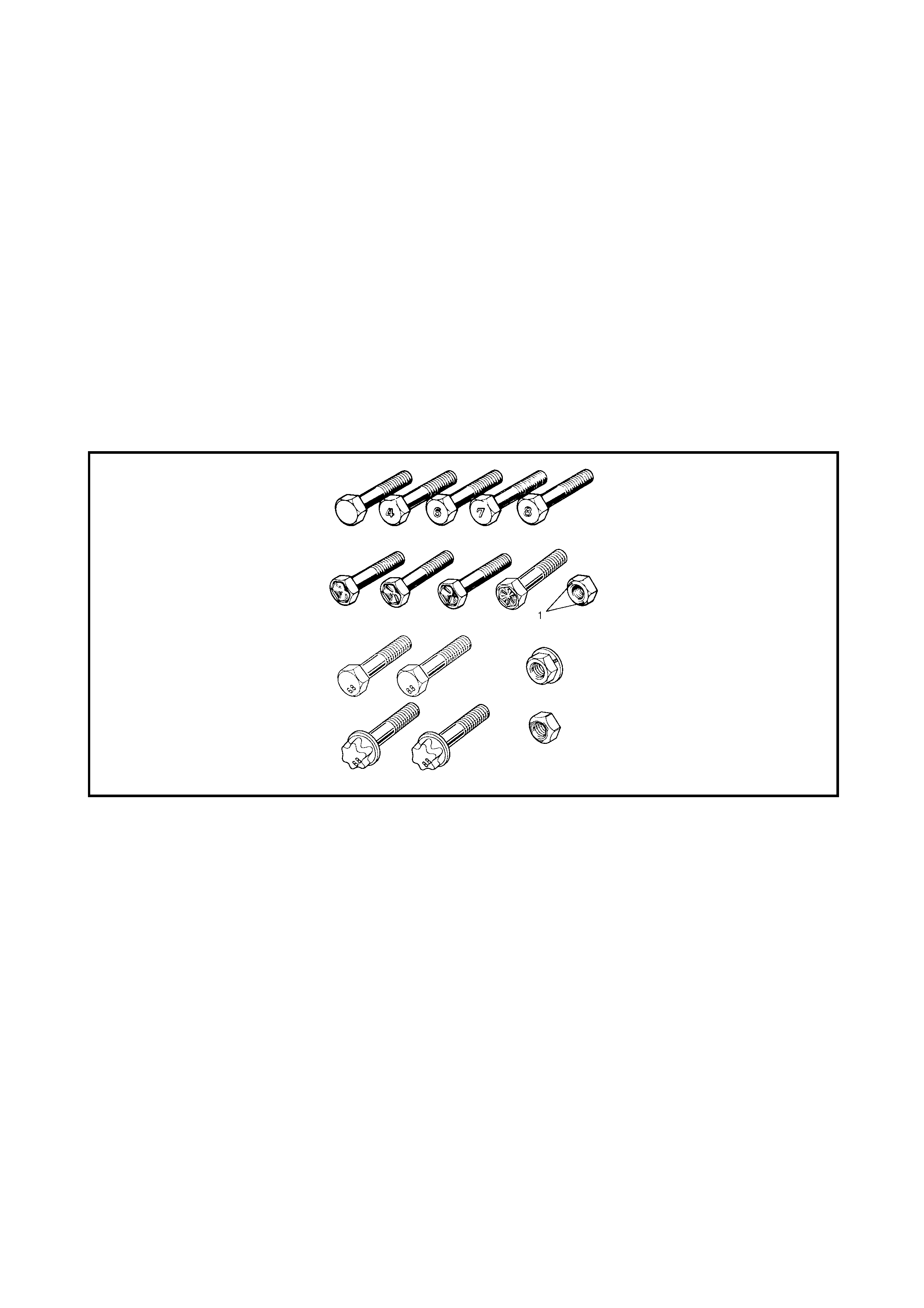
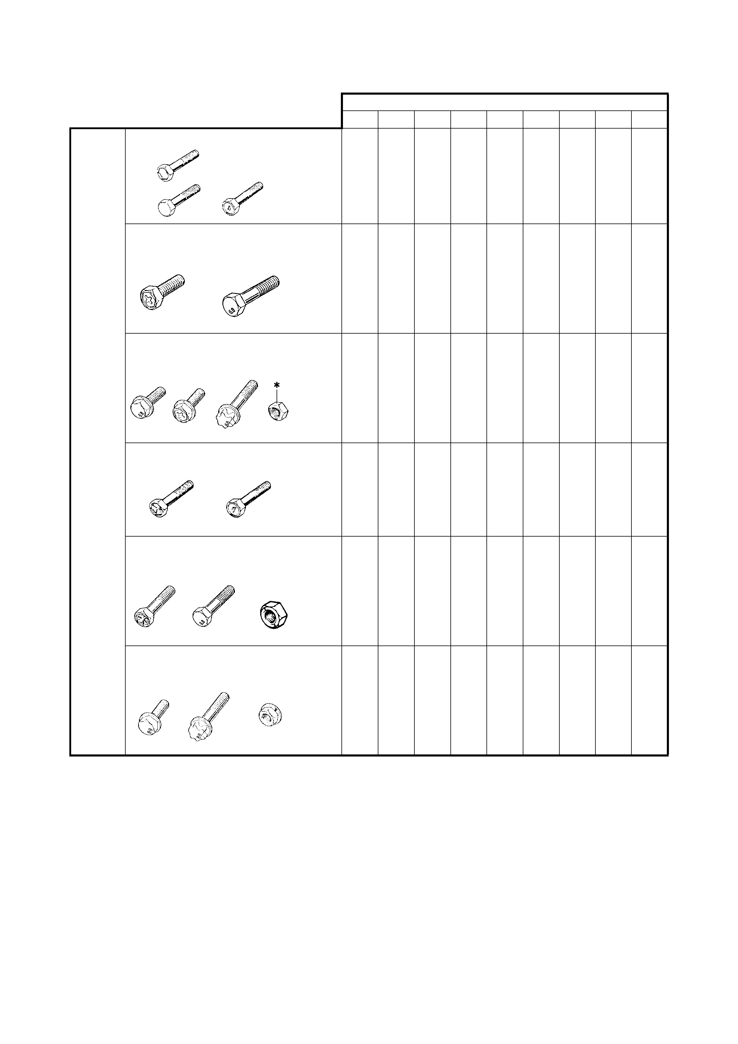
6.2 FASTENER STRENGTH IDENTIFICATION
Most co mmonly us ed metric fas tener streng th property c lasses are 4T, 6.8, 7T, 8.8 and rad ial line. The cl ass
identification is embossed on the head of each bolt. Some metric nuts will be marked with punched with a 6 or
8 strength identification mark on the nut face (1). The figure shows the different strength markings.
When replacing metric fasteners, be careful to use bolts and nuts of the same strength or greater than the
original fasteners (the same number marking or higher). It is also important to select replacement fasteners of
the correct diameter and thread pitch.
6.3 STANDARD TIGHTENING TORQUE
Each fas tener should be tightened to the tor que specifi ed in each Secti on of this manua l. If no description or
specification is provided, refer to the following tightening torque chart for the applicable torque for each fas-
tener. When a fastener of greater strength than the original one is used, use the torque specified for the origi-
nal fastener.
NOTE:
• For the flanged bolt, flanged nut and self-lock nut of 4T and 7T strength, add 10% to the tightening torque
given in the chart below.
• The chart below is applicable only where the fastened parts are made of steel or light alloy.
TIGHTENING TORQUE CHART
Thread Diameter (Nominal Diameter) (mm)
4 5 6 8 10 12 14 16 18
Strength
Equivalent of 4T fastener (Nm)
1.5 3.0 5.5 13 29 45 65 105 160
Equivalent of 6.8 fastener without
flange (Nm)
2.4 4.7 8.4 20 42 80 125 193 280
Equivalent of 6.8 fastener with flange
(Nm)
2.4 4.9 8.8 21 44 84 133 203 298
Equivalent of 7T fastener (Nm)
2.3 4.5 10 23 50 85 135 210 240
Equivalent of 8.8 fastener without
flange (Nm)
3.1 6.3 11 27 56 105 168 258 373
Equivalent of 8.8 fastener with flange
(Nm)
3.2 6.5 12 29 59 113 175 270 395
7. CONSOLIDATED TOOL LIST
The following consolidated tool list table lists the special service tools required for use on the Holden Cruze
(YGM) vehicle. The tools are listed in numerical order and include the SPX equivalent part number (if avail-
able), an illustrated reference and the tools classification (category).
The tools are classified in the following Categories:
Mandatory
Desirable
Available
Unique
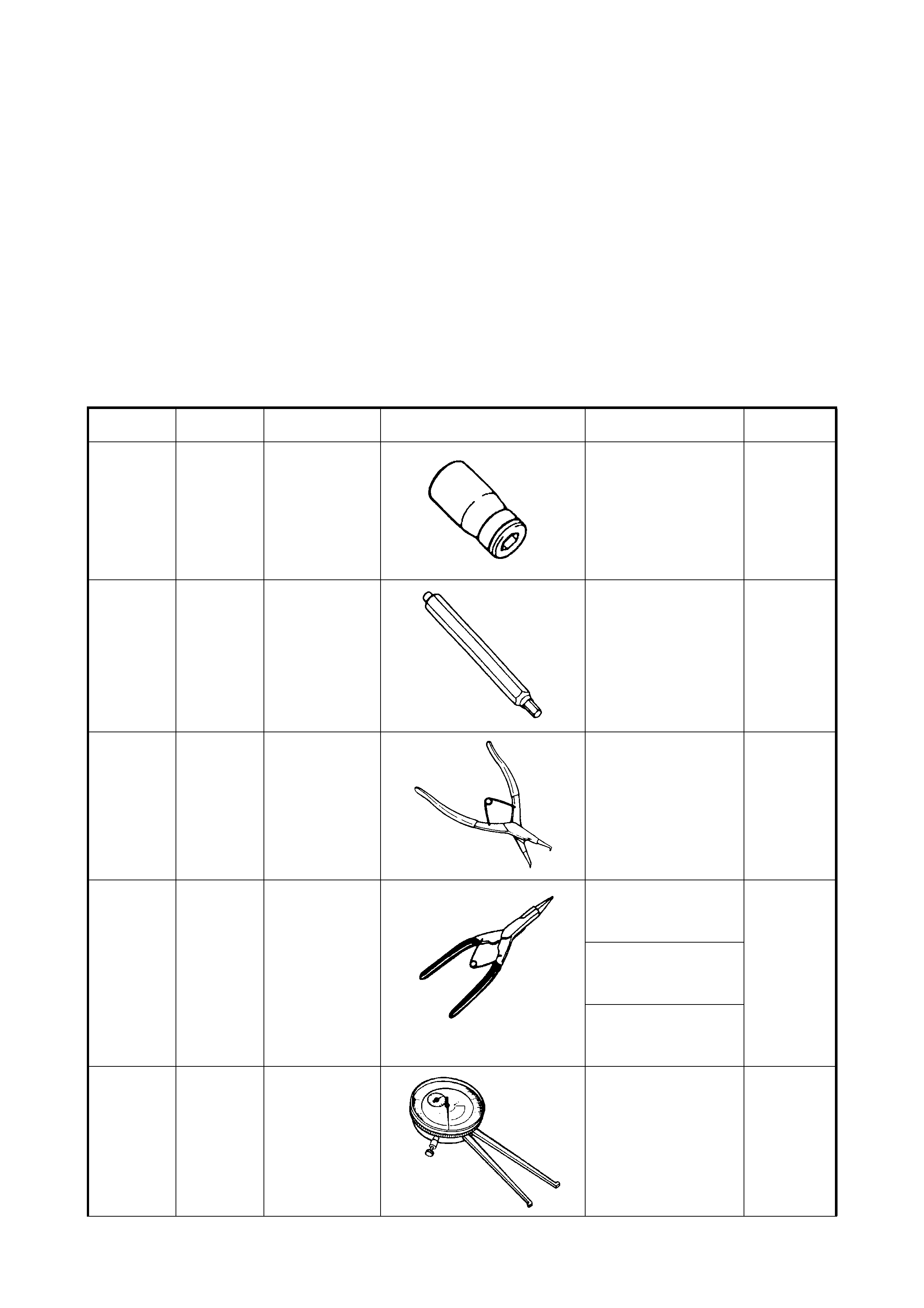
CONSOLIDATED TOOL LIST TABLE
Tool No. Spx
Tool No. Description Illustration Section
Number /usage Category
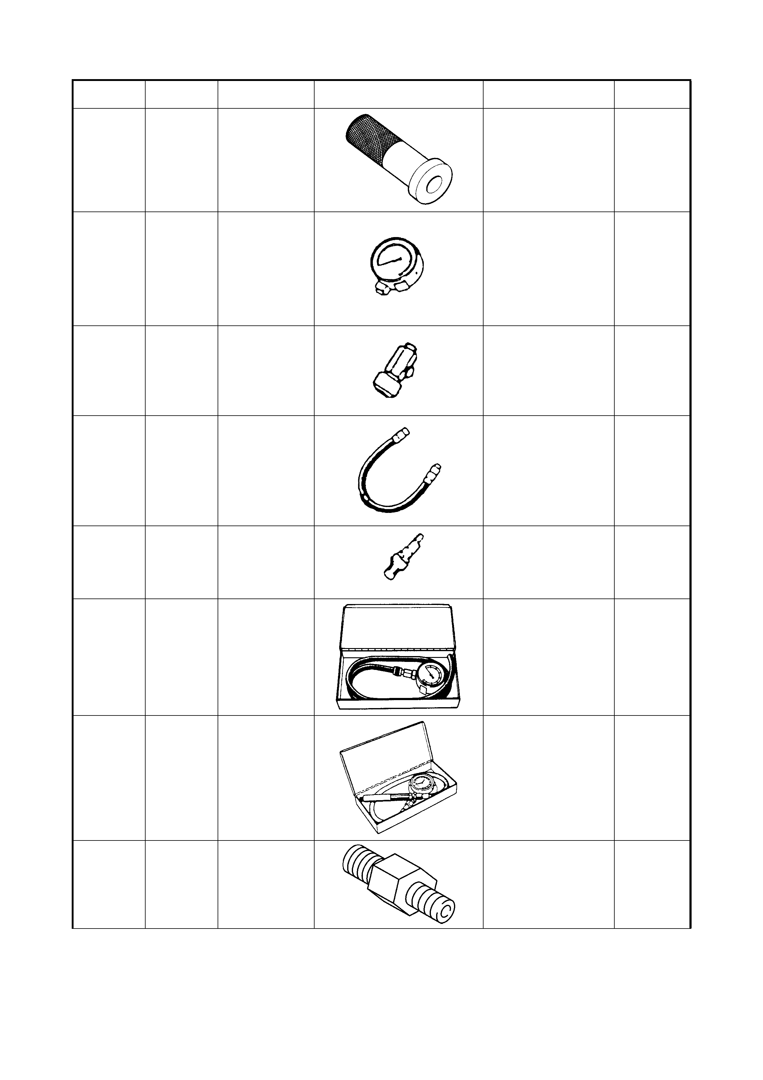
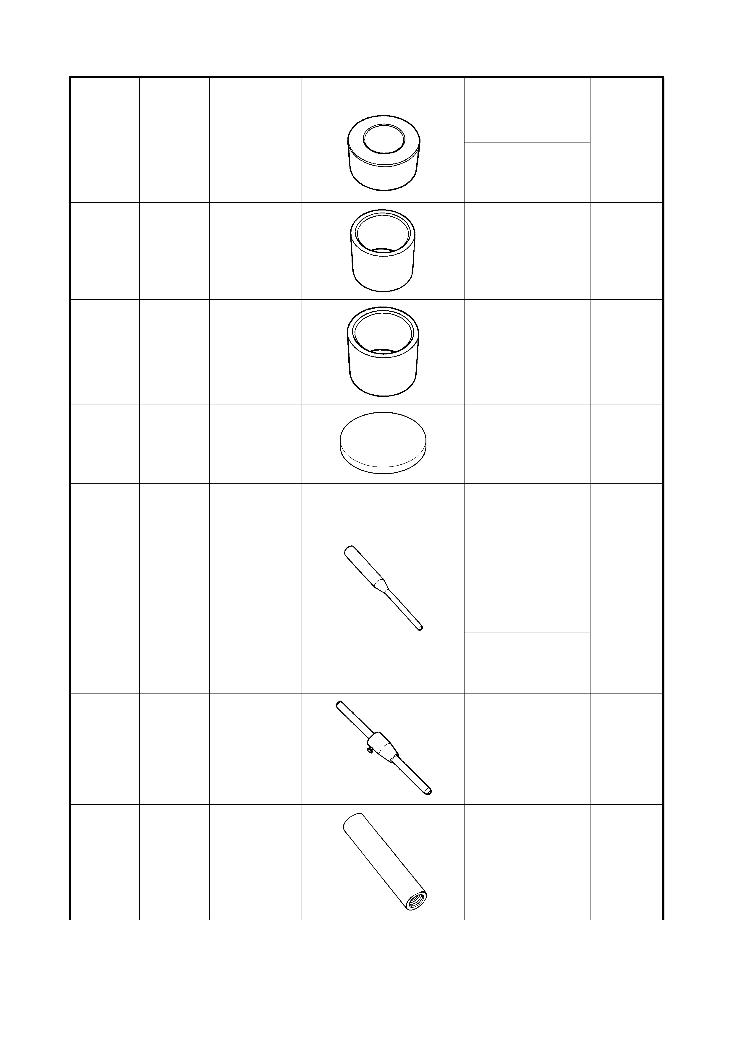
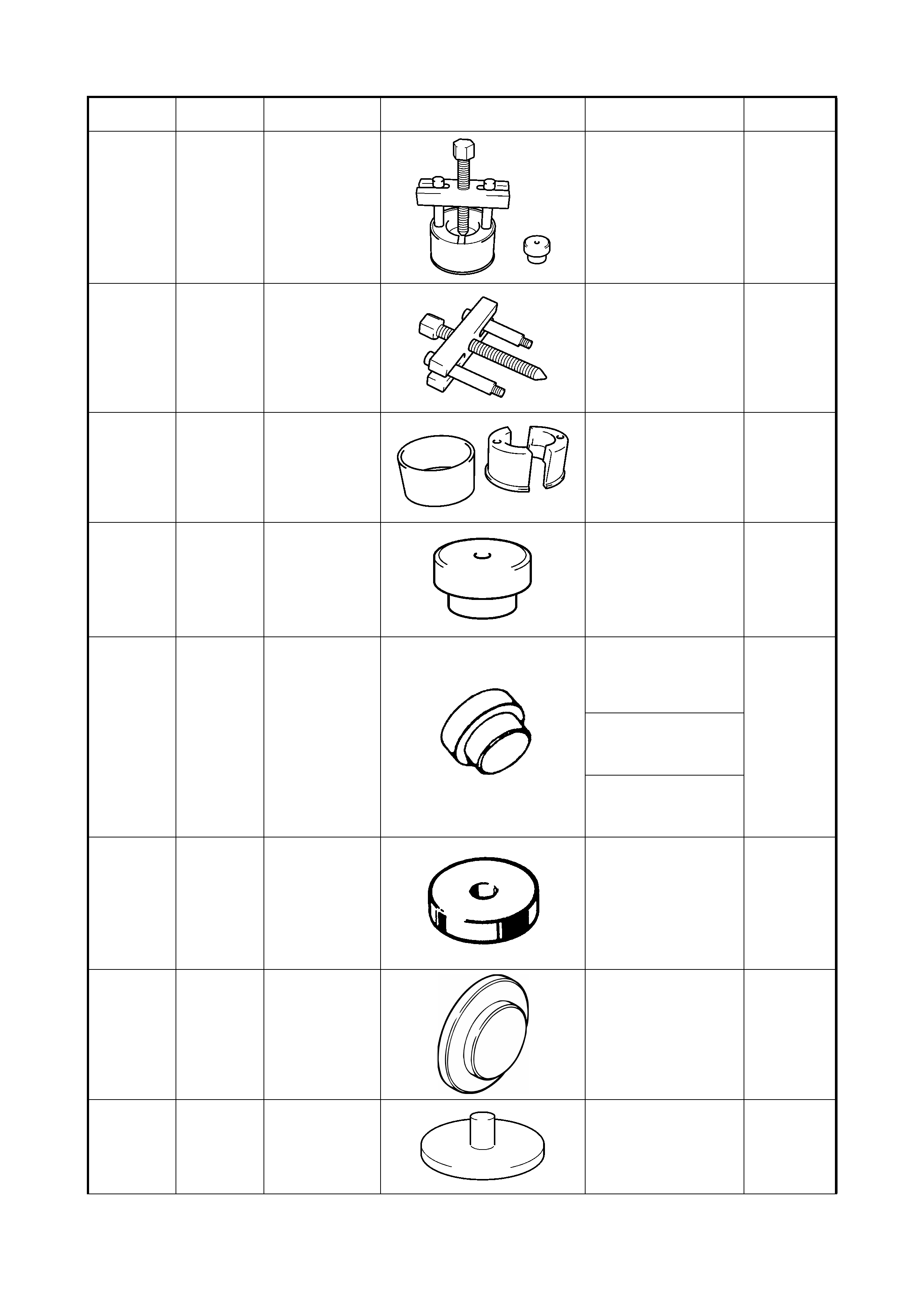
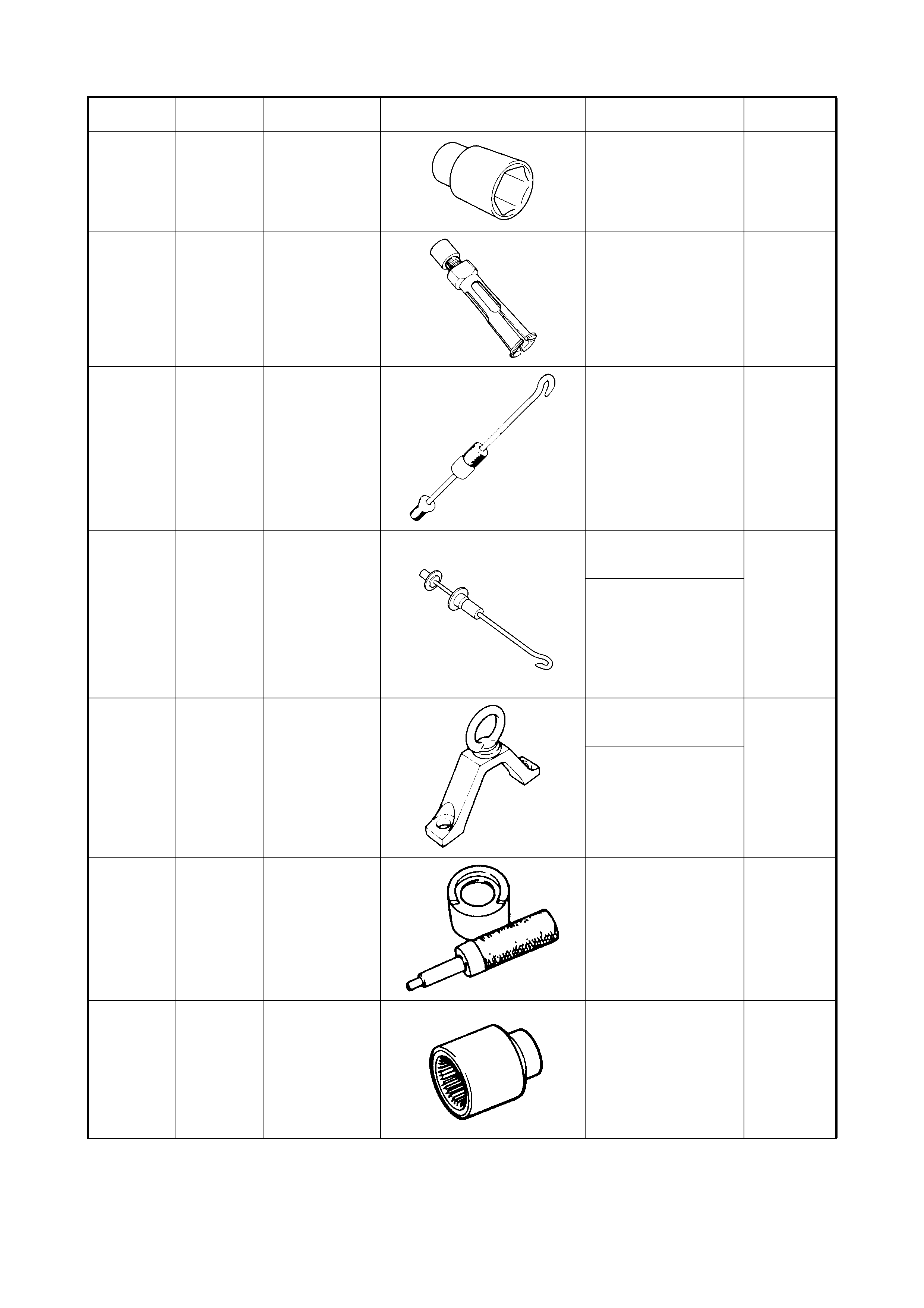
09900-00411 HEXAGON
WRENCH
SOCKET
3D - FRONT
SUSPENSION
• Strut nut loosening/
removal/installation
Available
09900-00414 HEXAGON
WRENCH BIT 6
mm
3D - FRONT
SUSPENSION
• Strut nut loosening/
removal/installation
Unique
09900-06106 SNAP RING
REMOVER 5 – BRAKES
• Mast er cylinder sleeve
cup removal
Available
09900-06107
SNAP RING
PLIERS
(OPEN
TYPE)
1B - AIR CONDITIONING
• Compressor clutch
circlips removal/
installation
Available
4A – FRONT DRIVE
SHAFT
• Cage circlip removal/
installation
7A - MANUAL
TRANSAXLE
• Fifth gear circlip
removal/installation
09900-20605 DIAL CALIPER
GAUGE 7B - AUTOMATIC
TRANSAXLE
• Oil pump stator shaft
bush bore measurement
• Oil pump stator body
bush bore measurement
• Transaxle rear cover
bush bore measurement
Available
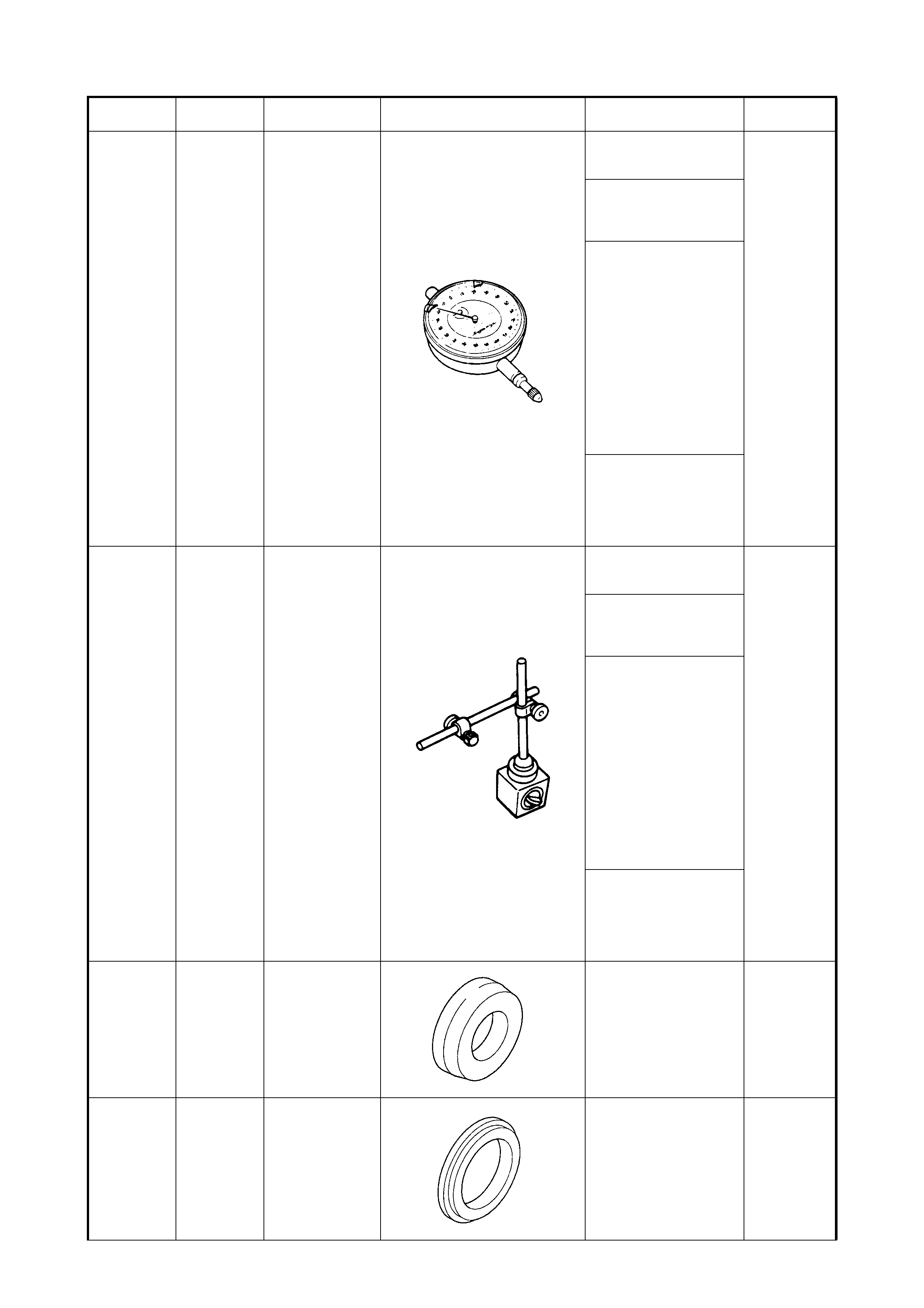
09900-20607 DIAL GAUGE 5 – BRAKES
• Front disc deflection
measurement
Available
7A - MANUAL
TRANSAXLE
• Differential gear thrust
play measurement
7B - AUTOMAT IC
TRANSAXLE
• Differential gear thrust
play measurement
•1
st
and reverse brake
piston stroke
measurement
• Input shaft thrust play
• Direct clutch piston
stroke measurement
• Reverse clutch piston
stroke measurement
• Forward clutch piston
stroke measurement
7F - REAR
DIFFERENTIAL
• Differential gear thrust
play measurement
• Drive bevel gear
backlash mea surem ent
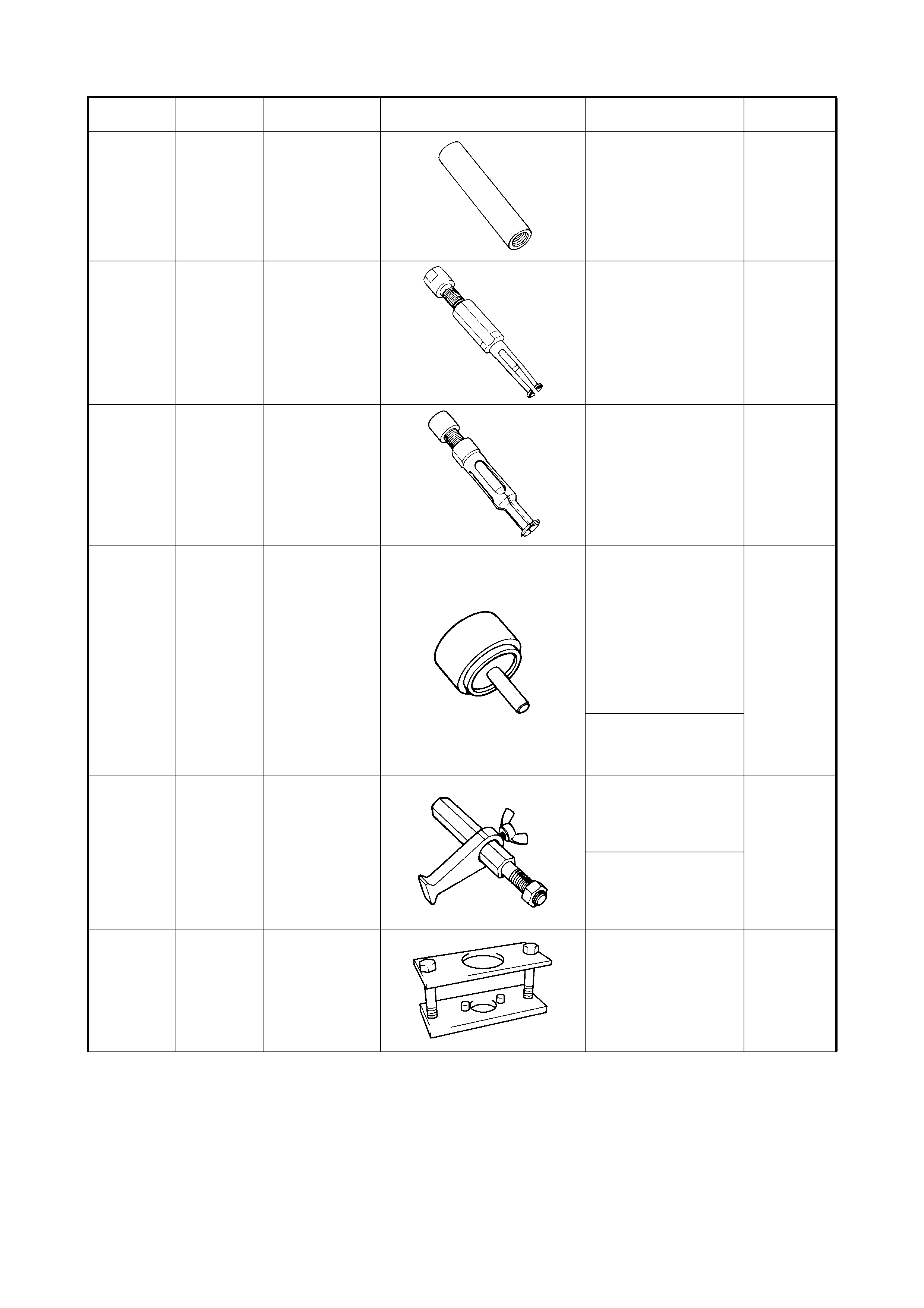
09900-20701 MAGNETIC
STAND 5 – BRAKES
• Front disc deflection
measurement
Available
7A - MANUAL
TRANSAXLE
• Differential gear thrust
play measurement
7B - AUTOMAT IC
TRANSAXLE
• Differential gear thrust
play measurement
•1
st
and reverse brake
piston stroke
measurement
• Input shaft thrust play
• Direct clutch piston
stroke measurement
• Reverse clutch piston
stroke measurement
• Forward clutch piston
stroke measurement
7F - REAR
DIFFERENTIAL
Diff erential gear thrust pl ay
measurement
Drive bevel gear backlash
measurement
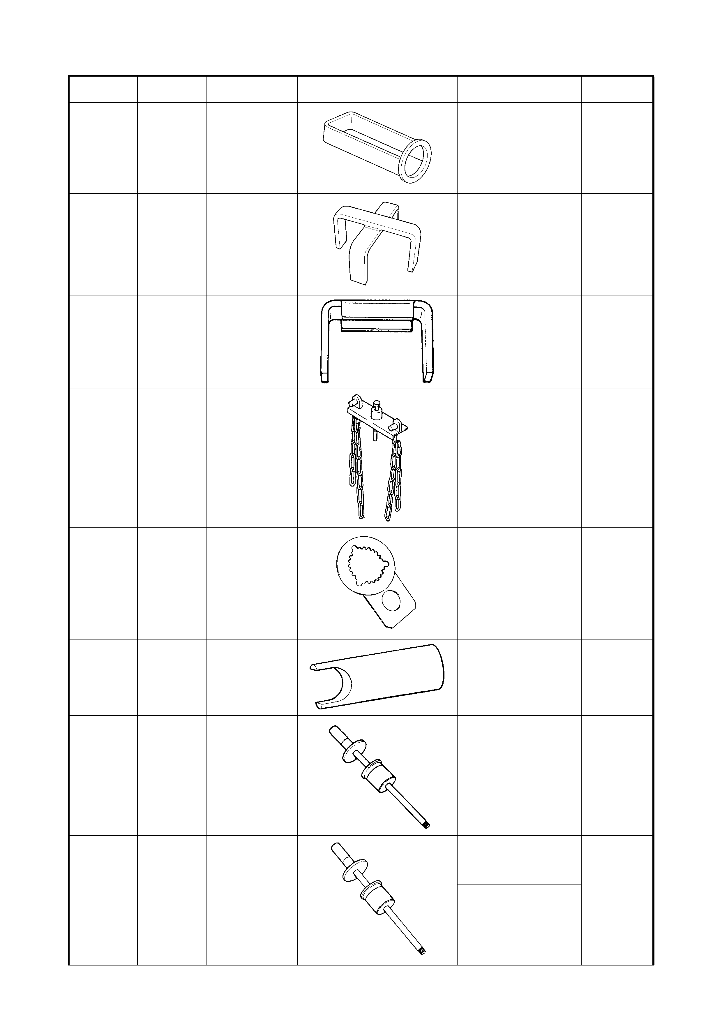
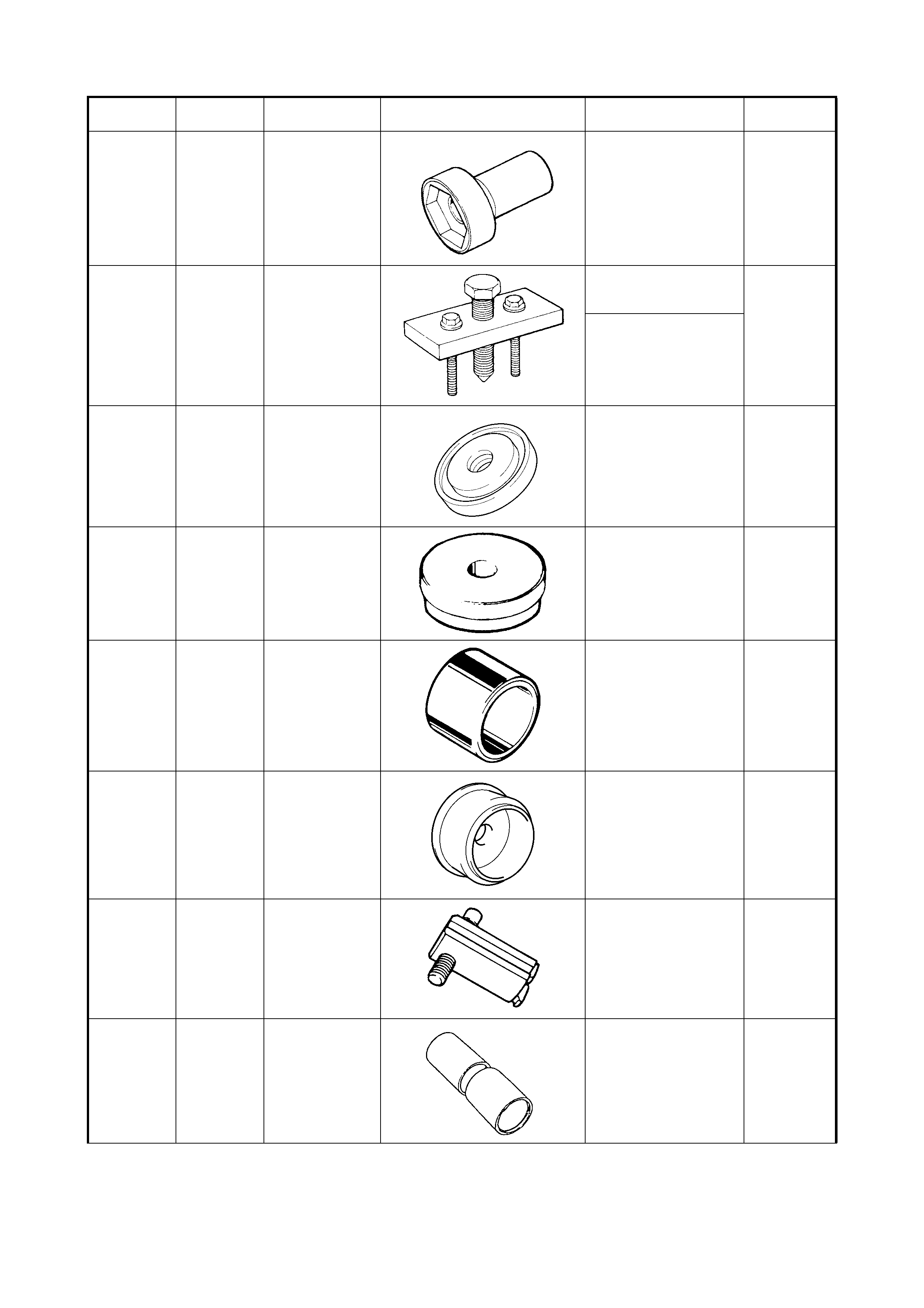
09911-97720 OIL SEAL GUIDE 6A1 - ENGINE
MECHANICAL (M15)
• Rear oil seal housing
bolts installation
Unique
09911-97820 OIL SEAL
INSTALLER 6A1 - ENGINE MECHANI-
CAL (M15)
• Rear oil seal installation
Unique
Tool No. Spx
Tool No. Description Illustration Section
Number /usage Category
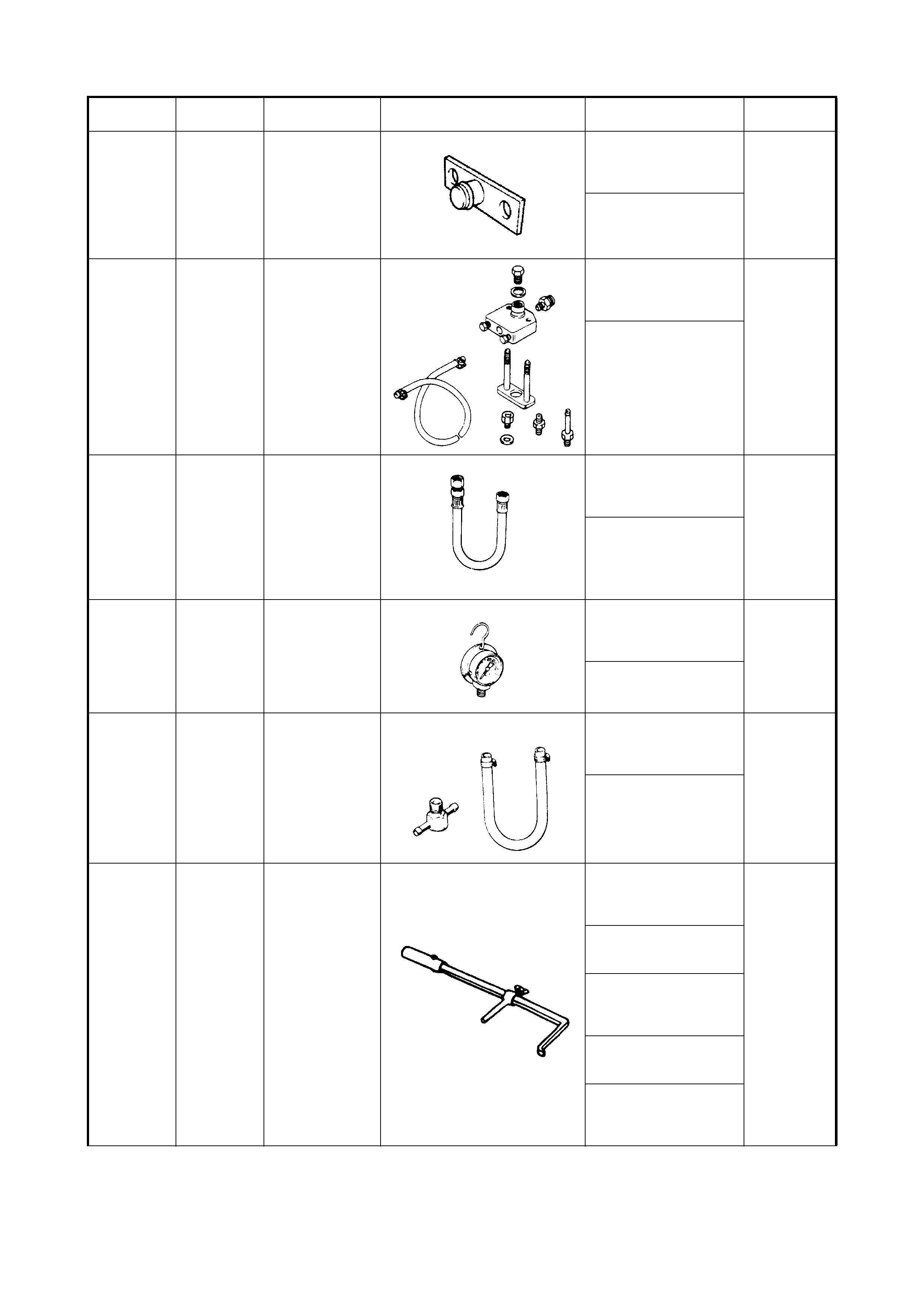
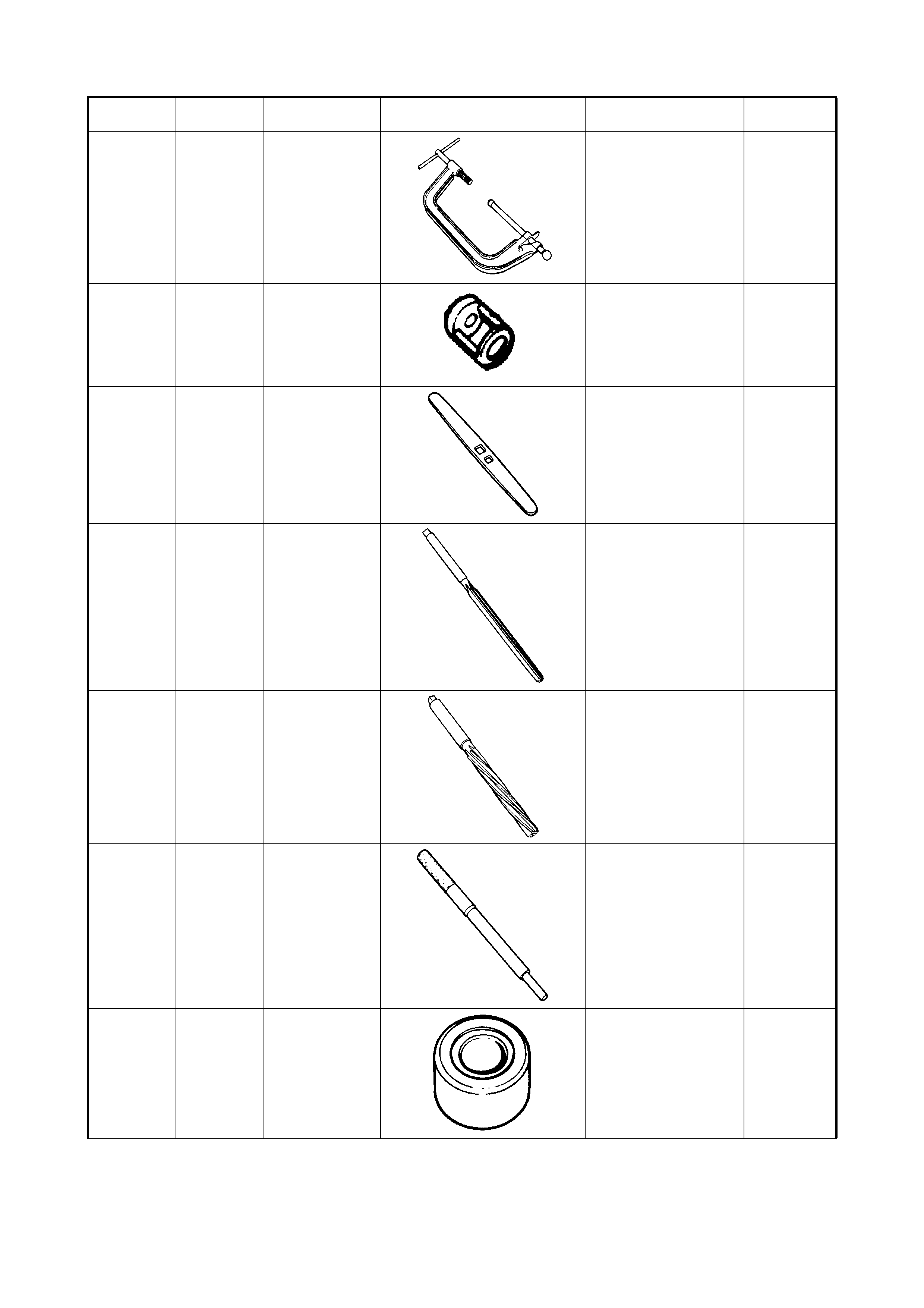
09912-57610 CHECKING TOOL
PLATE 6 - ENGINE GENERAL
INFORMATION &
DIAGNOSIS
• Diagnosis
Desirable
6E1 - ENGINE AND EMIS-
SION CONTROL SYSTEM
• Fuel injector diagnosis
09912-58421 CHECKING TOOL
SET 6 - ENGINE GENERAL
INFORMATION &
DIAGNOSIS
• Diagnosis
Desirable
6E1 - ENGINE AND EMIS-
SION CONTROL SYSTEM
• Fuel injector diagnosis
09912-58431 As an
alternative
use hose
SD28057
(released for
‘V’ and ‘W’
car) w i th the
quick connect
release tools
removed
PRESSURE HOSE 6 - ENGINE GENERAL
INFORMATION &
DIAGNOSIS
• Fuel press ure test
Mandatory
6E1 - ENGINE AND EMIS-
SION CONTROL SYSTEM
• Fuel press ure inspection
09912-58441 As an
alternative
use AU338 or
SD 28018
PRESSURE
GAUGE 6 - ENGINE GENERAL
INFORMATION &
DIAGNOSIS
• Fuel press ure test
Mandatory
6E1 - ENGINE AND EMIS-
SION CONTROL SYSTEM
• Fuel press ure inspection
09912-58490 Refer to
09912-58431 3-WAY JOINT &
HOSE 6 - ENGINE GENE RAL
INFORMATION &
DIAGNOSIS
• Fuel press ure test
Mandatory
6E1 - ENGINE AND EMIS-
SION CONTROL SYSTEM
• Fuel press ure inspection
09913-50121 OIL SEAL
REMOVER 3B - MANUAL RACK AND
PINION
• Pinion bearing plug oil
seal removal
Unique
3E - REAR SUSPENSION
• Rear axle shaft oil seal
removal
7B - AUTOMAT IC
TRANSAXLE
• Oil pump body oil seal
removal
7D – TRANSFER
• Pinion shaft oil seal
removal
7F - REAR
DIFFERENTIAL
• Differential carrier oil
seal removal
Tool No. Spx
Tool No. Description Illustration Section
Number /usage Category
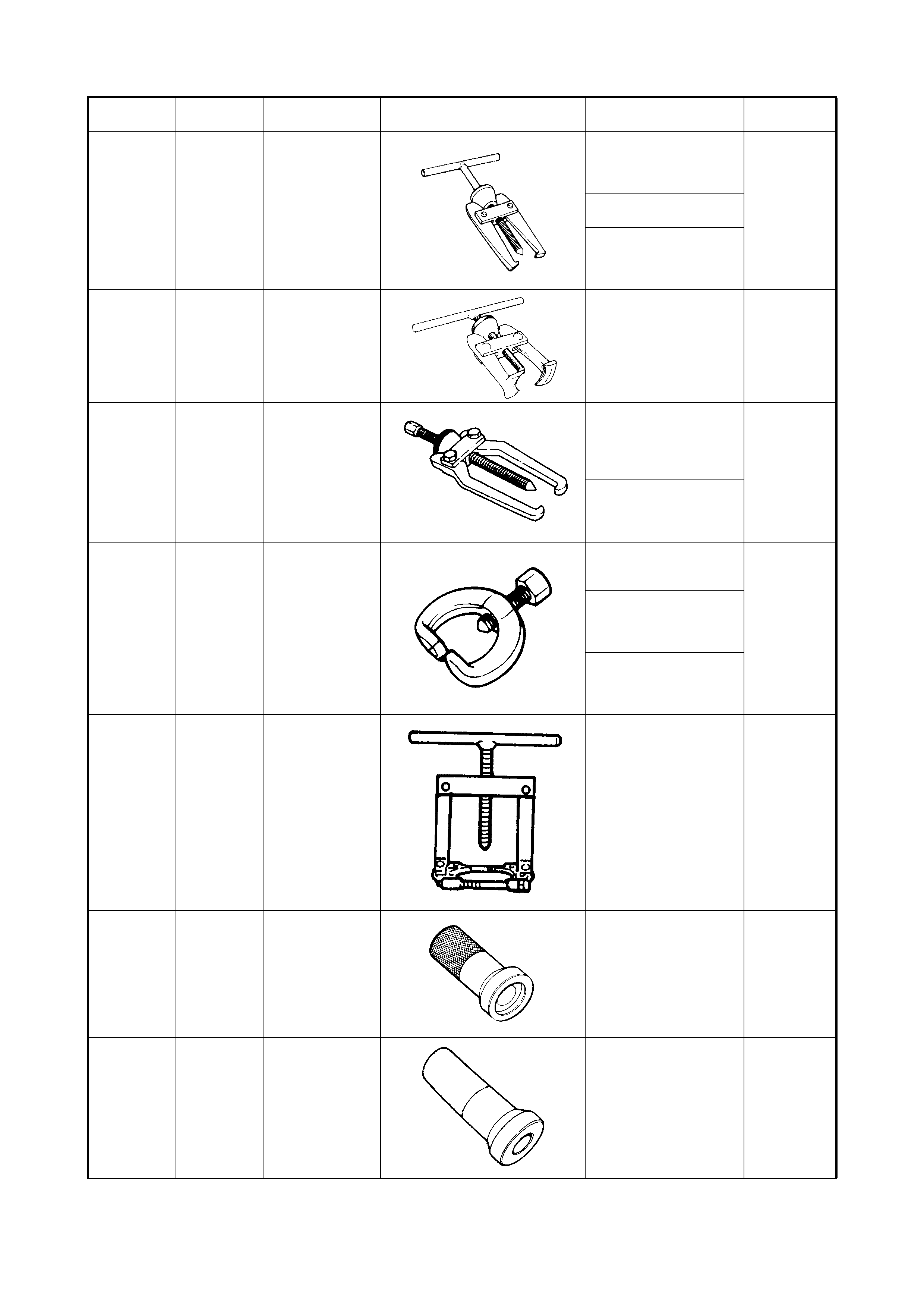
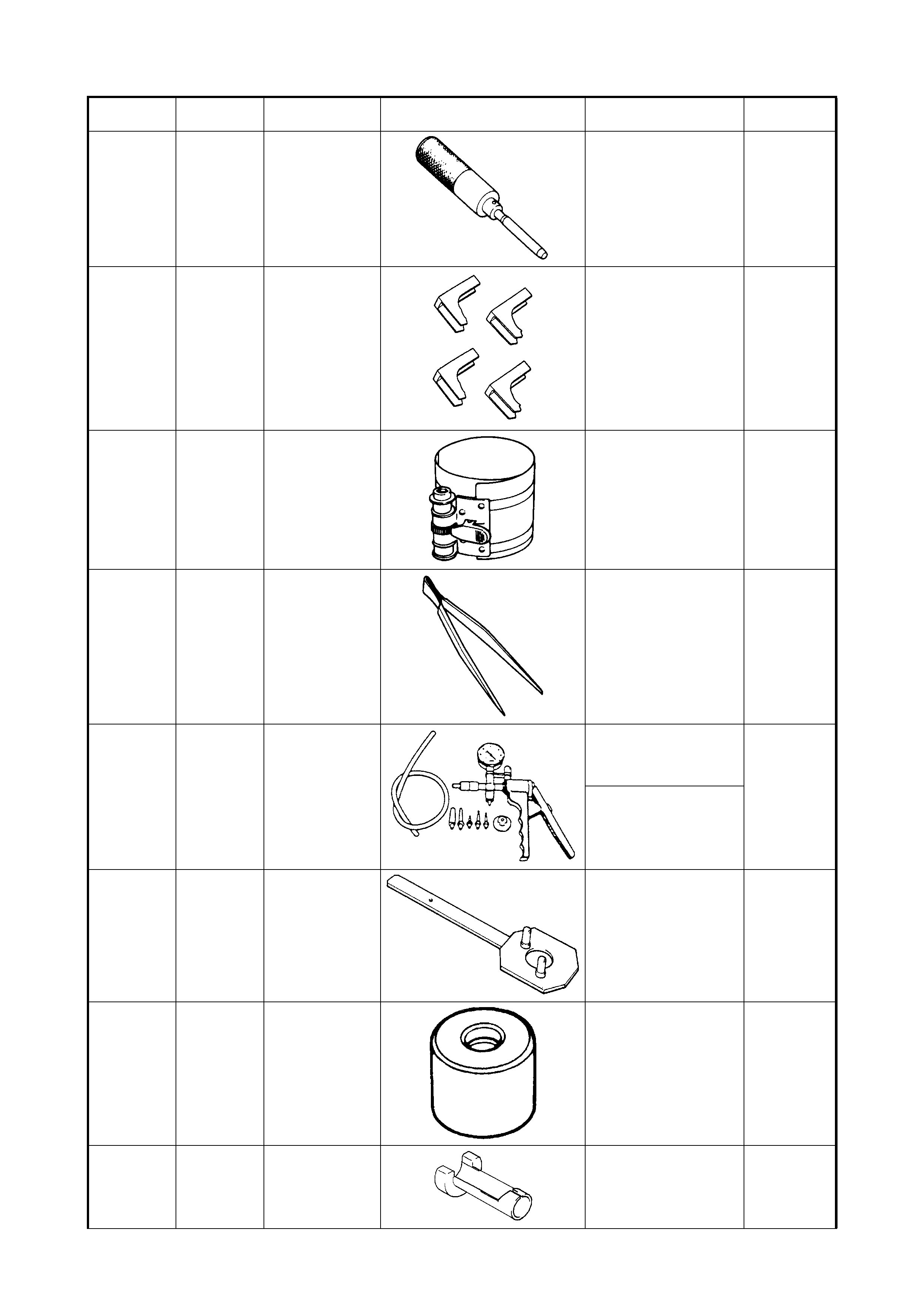
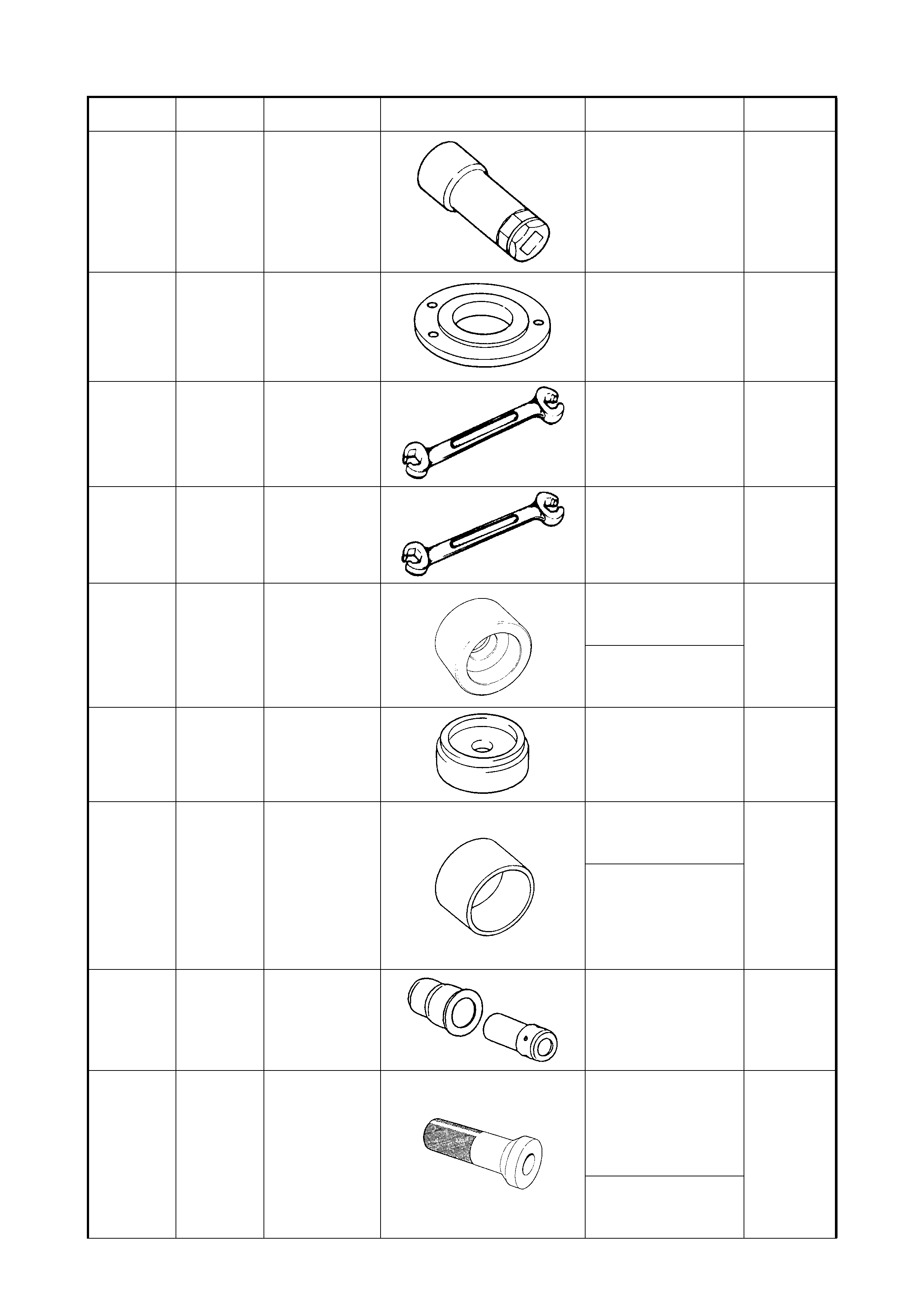
09913-60910 E2M49 OR
21M16 BEARING/GEAR
PULLER 7A - MANUAL
TRANSAXLE
• Differential assembly
right/left bearing removal
Unique
7D – TRANSFER
• Flange removal
7F - REAR
DIFFERENTIAL
• Differential side bearings
removal
09913-61510 E21M16 BEARING PULLER 7B - AUTOMATIC
TRANSAXLE
• Countershaft RH
bearing removal
Unique
09913-65135 BEARING PULLER 7D – TRANSFER
• Left side driven gear
bearing removal
• Driven gear assem bly
bevel gear removal
Unique
7F - REAR
DIFFERENTIAL
• Companion flange drive
bevel pinion removal
09913-65210 7310 OR
7311 TIE-ROD END
REMOVER 3B - MANUAL RACK AND
PINION
• Tie rod end removal
Desirable
3D - FRONT
SUSPENSION
• Front tie rod end
removal
4A - FRONT DRI VE
SHAFT
• Front tie rod end
removal
09913-65810 BEARING PULLER 3D - FRONT
SUSPENSION
• Front wheel bearing
outside inner race
removal
Unique
09913-70123 BEARING
INSTALLER 7B - AUTOMATIC
TRANSAXLE
• Differential left/right side
bearing installation
Unique
09913-75510 BEARING
INSTALLER 3D - FRONT
SUSPENSION
• Front wheel bearing
installation
Unique
Tool No. Spx
Tool No. Description Illustration Section
Number /usage Category
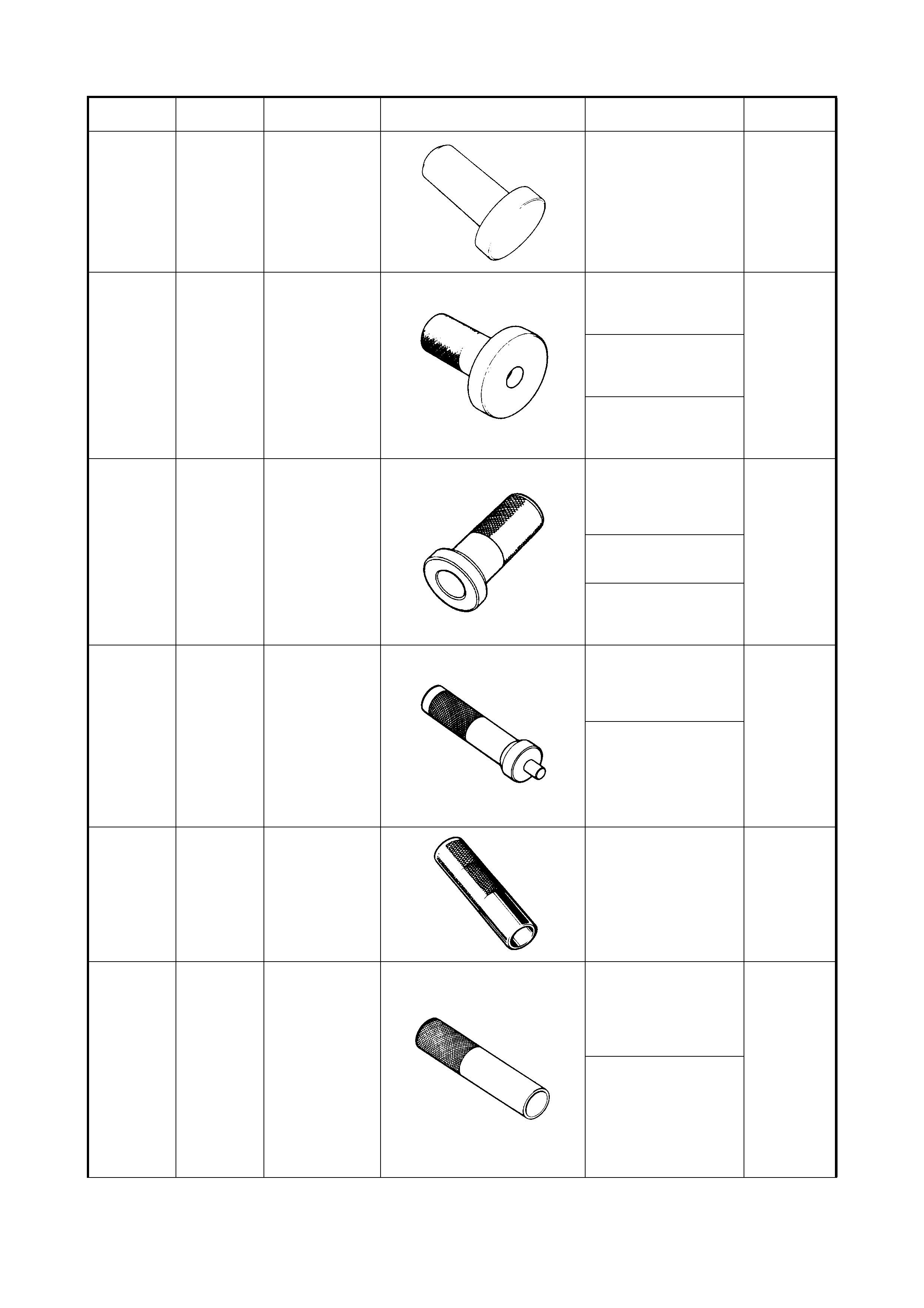
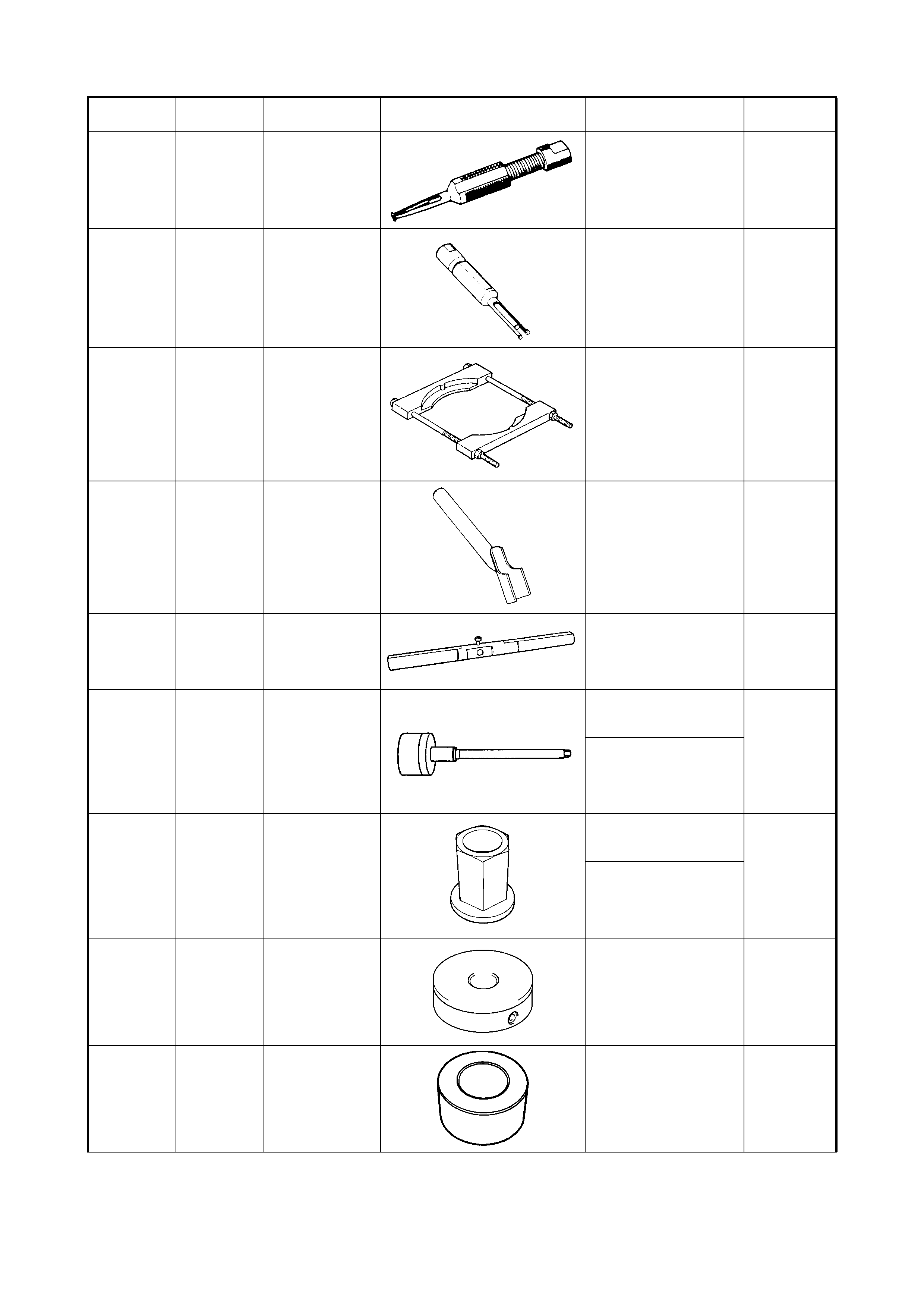
09913-75510 BEARING
INSTALLER 7A - MANUAL
TRANSAXLE
• Differential side oil seal
installation
• Differential sensor rotor
installation
Unique
09913-75520 BEARING
INSTALLER 3D - FRONT
SUSPENSION
• Front wheel bearing
removal/installation
Unique
6A1 - ENGINE
MECHANICAL (M15)
• Timing chain cover oil
seal
7B - AUTOMAT IC
TRANSAXLE
• Countershaft right hand
bearing cup installation
09913-75810 BEARING
INSTALLER 3D - FRONT
SUSPENSION
• Front wheel bearing
outside inner race
removal/installation
Unique
7D – TRANSFER
• Pinion shaft bearing
installation
7F - REAR
DIFFERENTIAL
Differential carrier oil seal
installation
09913-75821 BEARING
INSTALL ER
HANDLE
7B - AUTOMAT IC
TRANSAXLE
• Countershaft left hand
bearing cup and shim
installation
Unique
7D – TRANSFER
• Reduct ion drive gear oil
seals removal/
installation
• Pinion shaft bearing
outer races (front and
rear) installation
09913-80113 BEAR ING
INSTALLER 7A - MANUAL
TRANSAXLE
• Input drive shaft bearing
installation
•3
rd
gear and spacer
installation
Unique
09913-84510 BEARING
INSTALLER 7A - MANUAL
TRANSAXLE
• High speed sleeve and
hub installation
•5
th
gear countershaft
bearing cup installation
Unique
7B - AUTOMAT IC
TRANSAXLE
• Planetary ring gear
subassembly
• Countershaft reduction
driven gear installation
• Countershaft left hand
bearing installation
Tool No. Spx
Tool No. Description Illustration Section
Number /usage Category
09913-85210 BEARING
INSTALLER 7B - AUTOMATIC
TRANSAXLE
• Oil pump body seal
installation
Unique
09915-64510-
001 COMPRESSION
GAUGE 6A1 - ENGINE
MECHANICAL (M15)
• Engine compression
check
Available
09915-64510-
002 CONNECTOR 6A1 - ENGINE
MECHANICAL (M15)
• Engine compression
check
Available
09915-64530 HOSE 6A1 - ENGINE
MECHANICAL (M15)
• Engine compression
check
Available
09915-67010 ATTA CHME NT 6A1 - ENGINE
MECHANICAL (M15)
• Engine compression
check
Available
09915-67310 J23738-A VACUUM GAUGE 6A1 - ENGINE
MECHANICAL (M15)
• Engine vacuum check
Available
09915-77310 OIL PRESSURE
GAUGE 6A1 - ENGINE
MECHANICAL (M15)
• Oil pressure check
Available
09915-78211 OIL PRESSURE
GAUGE
ATTACHMENT
6A1 - ENGINE
MECHANICAL (M15)
• Oil pressure check
Desirable
Tool No. Spx
Tool No. Description Illustration Section
Number /usage Category
09916-14510 VALV E LIFT ER 6A1 - ENGINE
MECHANICAL (M15)
• Valve spring
compression
Available
09916-14910 VALV E LIFTER
ATTACHMENT 6A1 - ENGINE
MECHANICAL (M15)
• Valve spring
compression
Available
09916-34542 REAMER HANDL E 6A1 - ENGINE
MECHANICAL (M15)
• Valve guide reaming
Unique
09916-34550 REAMER (5.5 mm ) 6A1 - ENGINE
MECHANICAL (M15)
• Valve guide bore
reaming
Unique
09916-37320 REAMER
(10.5mm) 6A1 - ENGINE
MECHANICAL (M15)
• Valve guide reaming
Unique
09916-44910 VALV E GU IDE
REMOVER 6A1 - ENGINE
MECHANICAL (M15)
• Valve guide removal
Unique
09916-56011 VALVE GUIDE
INSTALLER 6A1 - ENGINE
MECHANICAL (M15)
• Valve guide installation
Unique
Tool No. Spx
Tool No. Description Illustration Section
Number /usage Category
09916-58210 VALV E GU IDE
INSTALL ER
HANDLE
6A1 - ENGINE
MECHANICAL (M15)
• Valve guide installation
• Valve stem seal
installation
Unique
09916-67020 As alternative
use
J42689AUS
previously
released by
IGM for Light
Commercial
vehicle use
TAPPET HOLDER 6A1 - ENGINE
MECHANICAL (M15)
• Tappet retainer
Desirable
09916-77310 E 191 P ISTON RING
COMPRESSOR 6A1 - ENGINE
MECHANICAL (M15)
• Piston ring installation
Available
09916-84511 FORCEPS 6A1 - ENGINE
MECHANICAL (M15)
• Valve cotter removal
Available
09917-47010 J23738-A VACUUM PUMP
GAUGE 6 - ENGINE GENERAL
INFORMATION &
DIAGNOSIS
• Diagnosis
Mandatory -
previously
released
6C - ENGINE F UEL
09917-68221 CAMSHAFT LOCK
HOLDER 6A1 - ENGINE
MECHANICAL (M15)
• Crankshaft pulley
removal/installation
Desirable
09917-98221 VALVE STEM
SEAL INSTALLER 6A1 - ENGINE
MECHANICAL (M15)
• Valve stem seal
installation
Desirable
09919-47020 7370 OR
7371 QUICK JOINT
REMOVER 6C – ENGINE FUEL
• Fuel line joint
disconnection
Mandatory
Tool No. Spx
Tool No. Description Illustration Section
Number /usage Category
09921-20200 PINION BEARING
REMOVER 3B - MANUAL RACK AND
PINION
• Gear case pinion
bearing removal
Unique
09921-26020 BEARING
REMOVER 7C – CLUTCH
• Input shaf t bearing
removal
Unique
09921-57810 BEARING
REMOVER 3E – REAR SUS PE N SI ON
• Rear brake back plate
and wheel bearing
spacer
Unique
09922-46010 BUSH REMOVE R 7C – CLUTCH
• Clutch release sys tem
No. 2 bush removal/
installation
Unique
09922-76120 DUMMY SHAFT 7F - REAR
DIFFERENTIAL
• Differential carrier and
drive bevel pinion
adjustment
Unique
09922-76140 BEVEL PINION
SHAFT 7D – TRANSFER
• Transfer output retainer
assembly adjustment
Unique
7F - REAR
DIFFERENTIAL
• Differential carrier and
drive bevel pinion
adjustment
09922-76150 BEVEL PINION
NUT 7D – TRANSFER
• Transfer output retainer
assembly adjustment
Unique
7F - REAR
DIFFERENTIAL
• Differential carrier and
drive bevel pinion
adjustment
09922-76230 BEVEL GEAR
DUMMY 7F - REAR
DIFFERENTIAL
• Differential carrier and
drive bevel pinion
adjustment
Unique
09922-76320 REAR COLLAR 7F - REAR
DIFFERENTIAL
• Differential carrier and
drive bevel pinion
adjustment
Unique
Tool No. Spx
Tool No. Description Illustration Section
Number /usage Category
09922-76340 REAR COLLAR 7D – TRANSFER
• Transfer output retainer
assembly adjustment
Unique
7F - REAR
DIFFERENTIAL
• Differential carrier and
drive bevel pinion
adjustment
09922-76410 FRONT COLLAR 7F - REAR
DIFFERENTIAL
• Differential carrier and
drive bevel pinion
adjustment
Unique
09922-76430 FRONT COLLAR 7D – TRANSFER
• Transfer output retainer
assembly adjustment
Unique
09922-76510 GAUGE BLOCK 7F - REAR
DIFFERENTIAL
• Differential carrier and
drive bevel pinion
adjustment
Unique
09922-85811 SPRING PIN
REMOVER
(4.5mm)
7A - MANUAL
TRANSAXLE
•5
th
gear shift fork spring
pin removal/installation
•5
th
and reverse gear
shift cam spring pin
removal
•5
th
and reverse gear
shift guide shaft pin
removal
• Differential pinion shaft
pin removal
Unique
7F - REAR
DIFFERENTIAL
• Differential side pinion
shaft spring pin removal/
installation
09923-36320 CLUTCH CENTRE
GUIDE 7C – CLUTCH
• Clutch disc – flywheel
alignment
Unique
09923-46020 JOINT PIPE 7C – CLUTCH
• Clutch release sys tem
No. 1 bush removal
Unique
Tool No. Spx
Tool No. Description Illustration Section
Number /usage Category
09923-46030 JOINT PIPE 7C – CLUTCH
• Clutch release sys tem
No. 1 bush installation
Unique
09923-73210 BEARING
REMOVER 1B – AIR CONDITIONING
• Compres sor clutc h front
cylinder head lip seal
removal
Unique
09923-74510 BEARING
REMOVER 7A - MANUAL
TRANSAXLE
• Right input shaft oil seal
removal
Unique
09923-78210 BEARING
INSTALLER 7A - MANUAL
TRANSAXLE
• Countershaft right
bearing cone installation
• Countershaft low speed
sleeve and hub
assembly installat ion
•3
rd
gear and spacer
installation
• Countershaft left bearing
cone installation
Unique
7B - AUTOMAT IC
TRANSAXLE
• Planetary ring gear
subassembly
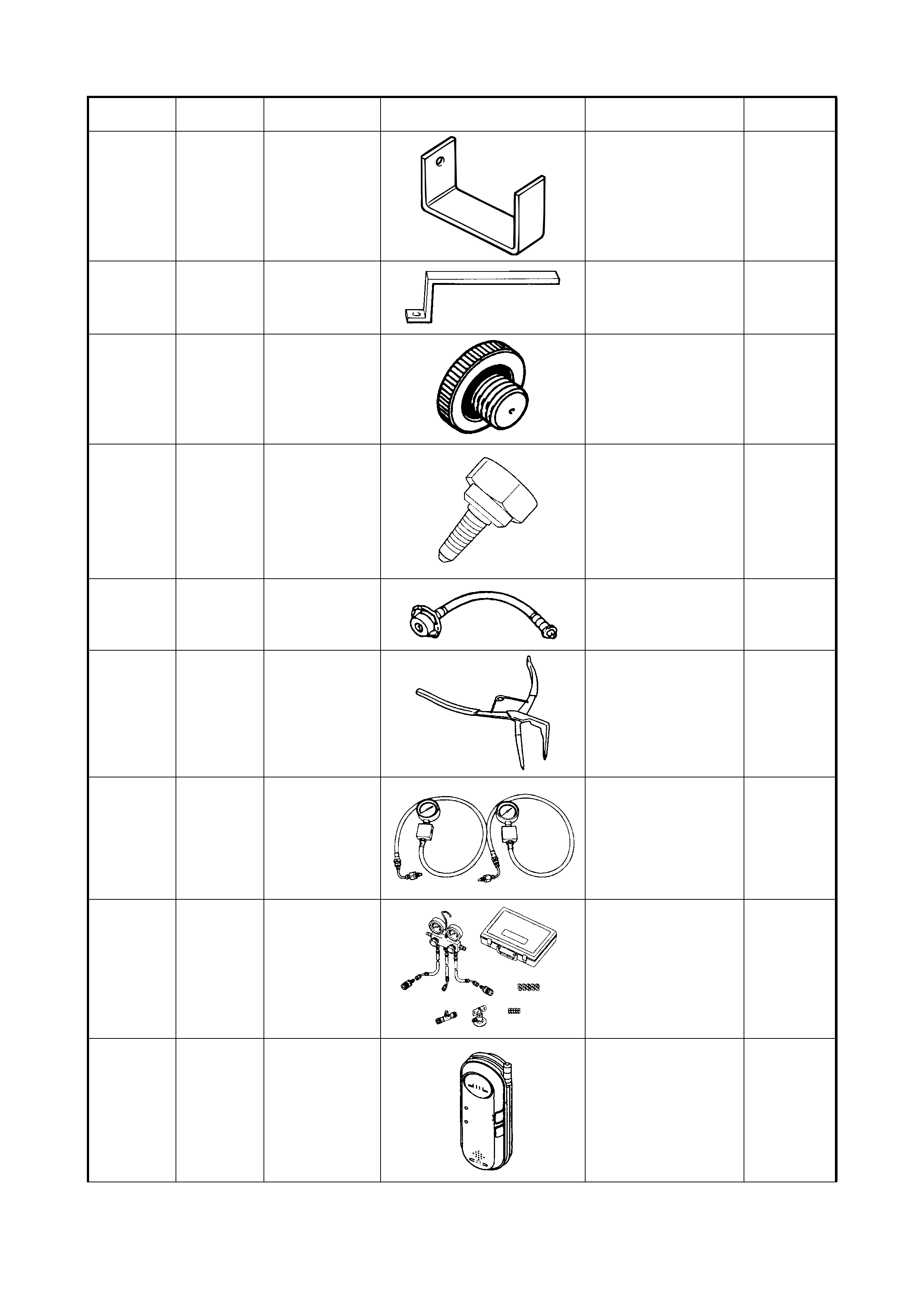
09924-17811 FLYWHEEL
HOLDER 6A1 - ENGINE
MECHANICAL (M15)
• Holds flywheel
stationary (clutch cover
bolts removal)
Desirable
7C – CLUTCH
• Holds flywheel
stationary (clutch cover
bolts removal)
• Flywhe el installation
09924-57610 GEAR HOLDER 7D – TRANSFER
• Bevel gear retainer
(bevel gear nut removal/
installation)
Unique
Tool No. Spx
Tool No. Description Illustration Section
Number /usage Category
09924-74510 BEARING
INSTALL ER
HANDLE
3E – REAR SUSPE NSI O N
• Rear axle shaft oil seal
installation
Unique
7A - MANUAL
TRANSAXLE
• Countershaft right
bearing cup
7B - AUTOMAT IC
TRANSAXLE
• Differential left/right side
oil seal installation
• Differential side left/right
hand bearing cup
installation
7D – TRANSFER
• Bevel pinion oil seal
installation
7F - REAR
DIFFERENTIAL
• Bevel pinion bearing
outer races installation
09924-84510-
002 BEARING
INSTALLER 7B - AUTOMATIC
TRANSAXLE
• Countershaft left hand
bearing cup and shim
installation
Unique
09924-84510-
005 BEARING
INSTALL ER
ATTACHMENT
7D – TRANSFER
• Reduct ion drive gear oil
seals removal/
installation
• Pinion shaft bearing
outer races (front and
rear) installation
Unique
09925-15410 OIL SEAL
INSTALLER 7D – TRANSFER
• Left/right case oil seal
installation
Unique
09925-18011 BEARING
INSTALLER 7A - MANUAL
TRANSAXLE
• Countershaft low speed
sleeve and hub
assembly
Unique
09925-37811-
001 OIL PRESSURE
GAUGE 7B - AUTOMATIC
TRANSAXLE
• Fluid pressure check
Desirable
09925-58210 OIL SEAL
INSTALLER 7D – TRANSFER
• Driven gear right side
bearing removal
Unique
Tool No. Spx
Tool No. Description Illustration Section
Number /usage Category
09925-68210 BEARING OU TER
RACE INSTALLER 7A - MANUAL
TRANSAXLE
• Countershaft right
bearing cup
Unique
09925-78210 SPRING PIN
REMOVER (6mm) 7A - MANUAL
TRANSAXLE
• Gear shift and select
lever spring pin removal
Unique
09925-88210 BEARING PULLER
ATTACHMENT 7A - MANUAL
TRANSAXLE
• Differential assembly
right/left bearing removal
Unique
7B - AUTOMAT IC
TRANSAXLE
• Countershaft reduction
driven gear installation
• Countershaft left hand
bearing installation
7F - REAR
DIFFERENTIAL
• Differential side bearings
removal
09925-98210 BEARING
INSTALLER 3B - MANUAL RACK AND
PINION
• Pinion bearing plug oil
seal installation
Unique
7B - AUTOMAT IC
TRANSAXLE
• Manual shif t shaft oil
seal installation
7C – CLUTCH
• Input shaf t bearing
installation
7F - REAR
DIFFERENTIAL
• Bevel pinion bearing
outer races installation
09925-98221 BEARING
INSTALLER 7A - MANUAL
TRANSAXLE
• Countershaft left bearing
cone installation
• Input shaf t left bearing
Unique
7B - AUTOMAT IC
TRANSAXLE
• Countershaft left hand
bearing and reduction
gear removal
7C – CLUTCH
• Clutch release shaft seal
installation
09926-27610 OIL SEAL
INSTALLER 7D – TRANSFER
• Bevel pinion oil seal
installation
Unique
Tool No. Spx
Tool No. Description Illustration Section
Number /usage Category
09926-37610 BEARING
INSTALLER 7B - AUTOMATIC
TRANSAXLE
• Differential left/right
hand side bearing
removal
Unique
09926-37610-
001 BEARING PULLER 7B - AUTOMA TIC
TRANSAXLE
• Differential left/right
hand side bearing
removal (part of 09926-
37610)
Unique
09926-37610-
002 BEARING PULLER
ATTACHMENT 7B - AUTOMATIC
TRANSAXLE
• Differential left/right
hand side bearing
removal (part of 09926-
37610)
Unique
09926-37610-
003 BEARING
REMOVER
ATTACHMENT
7B - AUTOMAT IC
TRANSAXLE
• Differential left/right
hand side bearing
removal (part of 09926-
37610)
Unique
09926-58010 BEARING PULLER
ATTACHMENT 3D - FRONT
SUSPENSION
• Front wheel bearing
outside inner race
removal
Unique
6A1 - ENGINE
MECHANICAL (M15)
• Crankshaft pulley
removal
7B - AUTOMAT IC
TRANSAXLE
• Countershaft RH
bearing removal
09926-68310 BEARING
INSTALLER 3D - FRONT
SUSPENSION
• Front wheel bearing
installation
Unique
09926-96030 CLUTCH SPRING
COMPRESSOR 7B - AUTOMAT IC
TRANSAXLE
• Transaxle rear cover
snap ring removal
• O/D and 2
nd
coast brake
return spring
subassembly installation
Unique
09926-96050 BRAKE PI STON
COMPRESSOR 7B - AUTOMAT IC
TRANSAXLE
•2
nd
brake piston snap
ring removal/inst allation
Unique
Tool No. Spx
Tool No. Description Illustration Section
Number /usage Category
09926-97610 SPRING
COMPRESSOR 7B - AUTOMAT IC
TRANSAXLE
• Forward and reverse
clutch assembly
balancer snap ring
removal/installation
Unique
09926-97620 SPRING
COMPRESSOR 7B - AUTOMAT IC
TRANSAXLE
•1
st
and reverse brake
piston return spring
compression (snap ring
removal/installation)
Unique
09926-98310 CLUTCH SPRING
COMPRESSOR 7B - AUTOMAT IC
TRANSAXLE
• Direct clutch assembly
input shaft snap ring
removal
Unique
09927-18411 UNIVERSAL
PULLER 3E - REAR SUSPENSI O N
• Rear brake back plate
and wheel bearing
spacer
Unique
09927-76010 GEAR HOLDER 7A - MANUAL
TRANSAXLE
• Counter shaft and input
shaft holder
(countershaft nut
removal/installation)
Unique
09928-06050 DIFFERENTIAL
PRELOAD
ADAPTER
7B - AUTOMAT IC
TRANSAXLE
• Differential side bearing
preload measurement
• Countershaft bearing
preload measurement
Unique
09930-30102 SLIDING SHAFT 3B - MANUAL RACK AND
PINION
• Gear case pinion
bearing removal
Unique
09930-30104 SLIDING SHAFT 7A - MANUAL
TRANSAXLE
• Right input shaft oil seal
removal
Unique
7C – CLUTCH
• Clutch release sys tem
No. 1 bush removal/
installation
Tool No. Spx
Tool No. Description Illustration Section
Number /usage Category
09930-40113 ROTOR HOLDER 7D – TRANSFER
• Transfer output retainer
assembly flange retainer
(flange nut removal)
Unique
7F - REAR
DIFFERENTIAL
• Companion flange
retainer (drive bevel
pinion nut removal/
installation
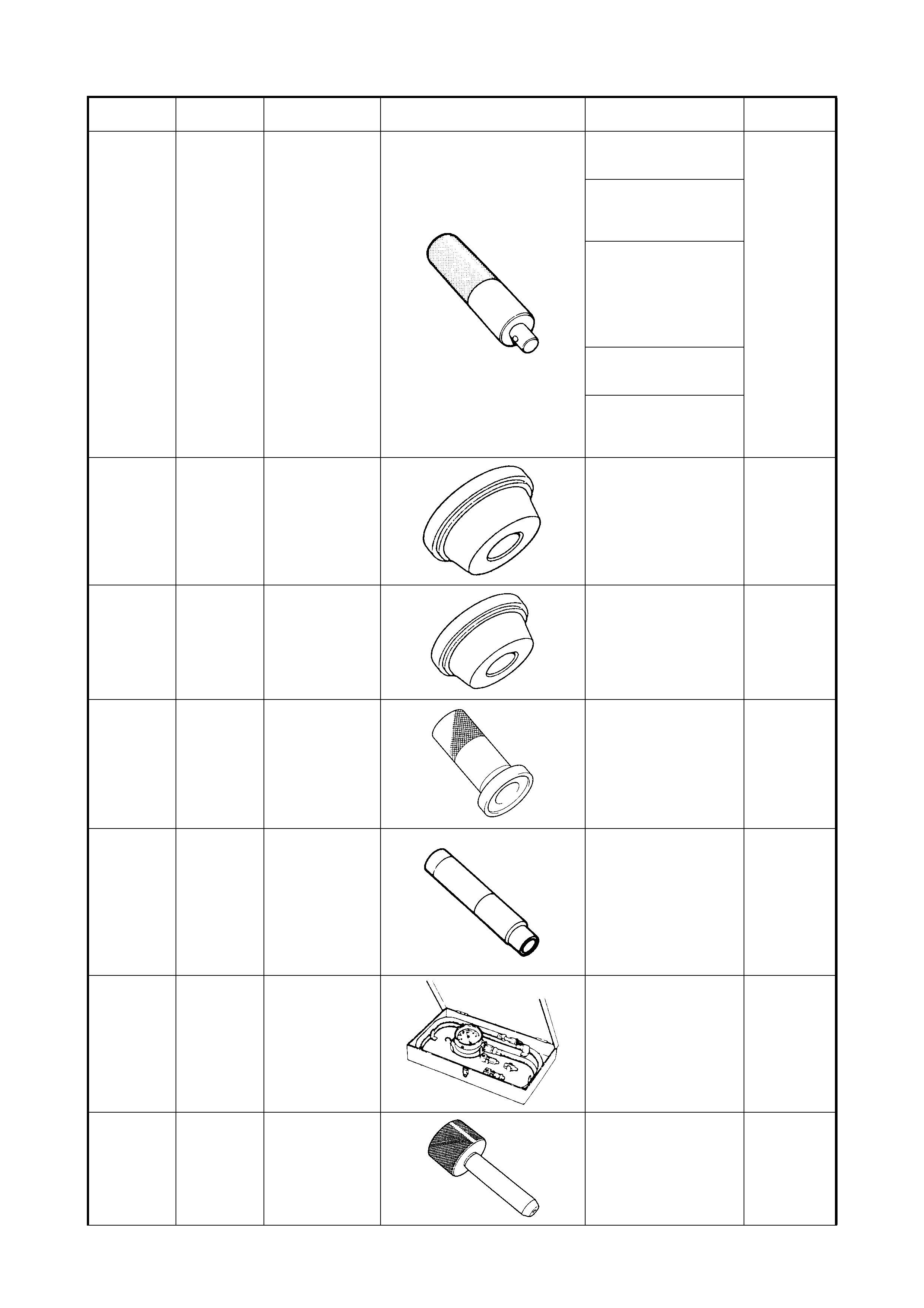
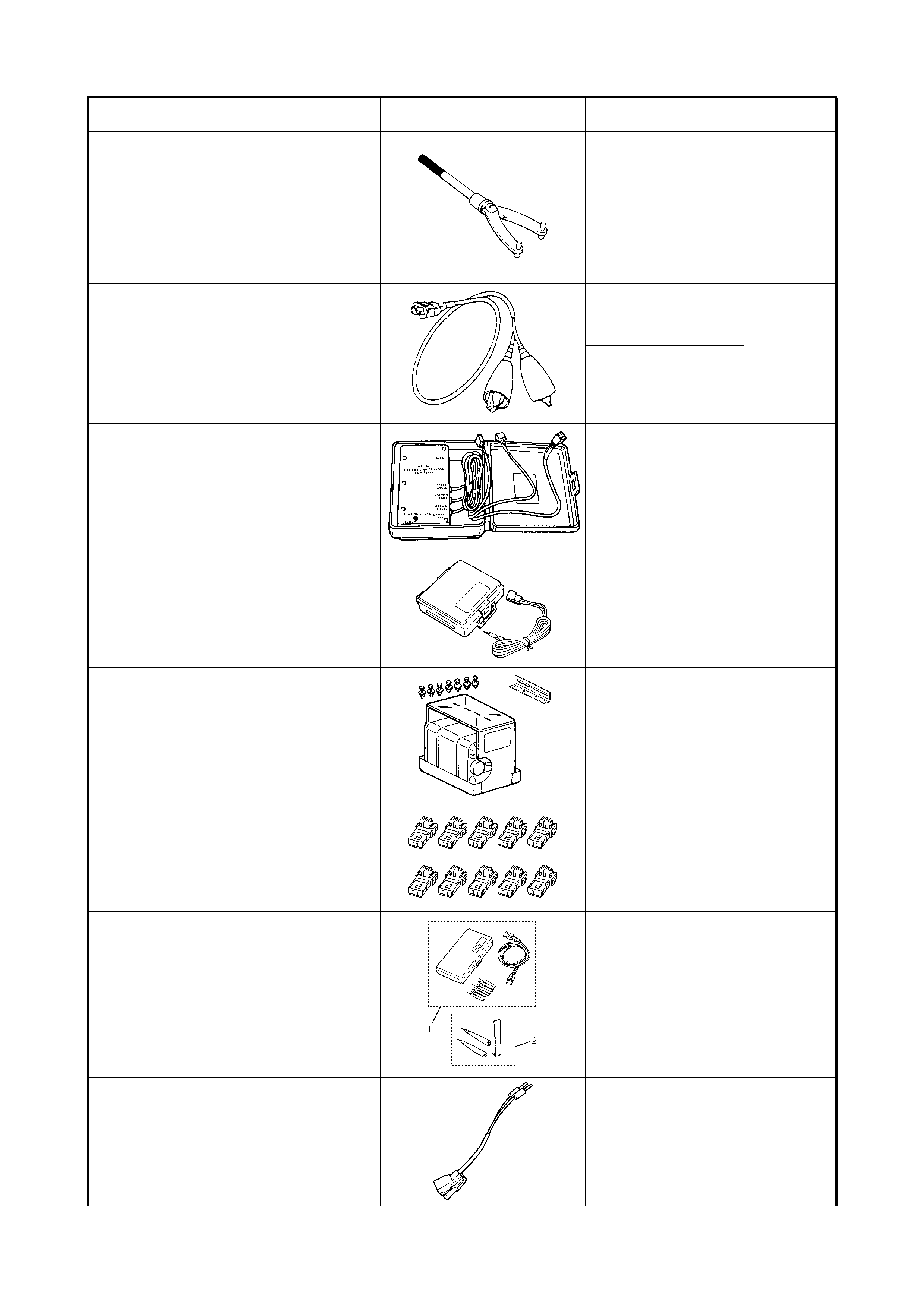
09930-88530 INJECTOR TEST
LEAD 6 – ENGINE GENERAL
INFORMATION &
DIAGNOSIS
• Diagnosis
Desirable
6E1 – ENGINE AND
EMISSION CONTROL
SYSTEM
• Fuel injector diagnosis
09932-75010 AIRBAG DRIVER /
PASSENGER
LOAD TOOL
10B - AIRBAG SY ST EM
• Safe ty (to prevent
accidental deployment)
and diagnosis
Mandatory
09932-75030 J41367 AIRBAG
DEPLOYMENT
HARNESS
10B - AIRBAG SY ST EM
• Airbag/seat belt
pretensioner activation
Unique
09932-75041 J39401-A PASSENGER
AIRBAG MODULE
DEPLOYMENT
FIXTURE
10B - AIRBAG SY ST EM
• Airbag deployment Unique
09932-75410 SPARE
CONNECTOR
(FOR ADAPTOR
CABLE 09932-
78331)
10B – AIRBAG SYSTEM
• Spares connectors for
adaptor cable 09932-
78331
Unique
09932-76010 J35616-A CONNECTOR
TEST ADAPTOR
SET
10B - AIRBAG SY ST EM
• Diagn osis – checking or
probing terminals
Items included
in No. 2 -
Mandatory
09932-78310 ADAPTER CABLE 10B - AIRBAG SYSTEM
• Diagnosis Mandatory
Tool No. Spx
Tool No. Description Illustration Section
Number /usage Category
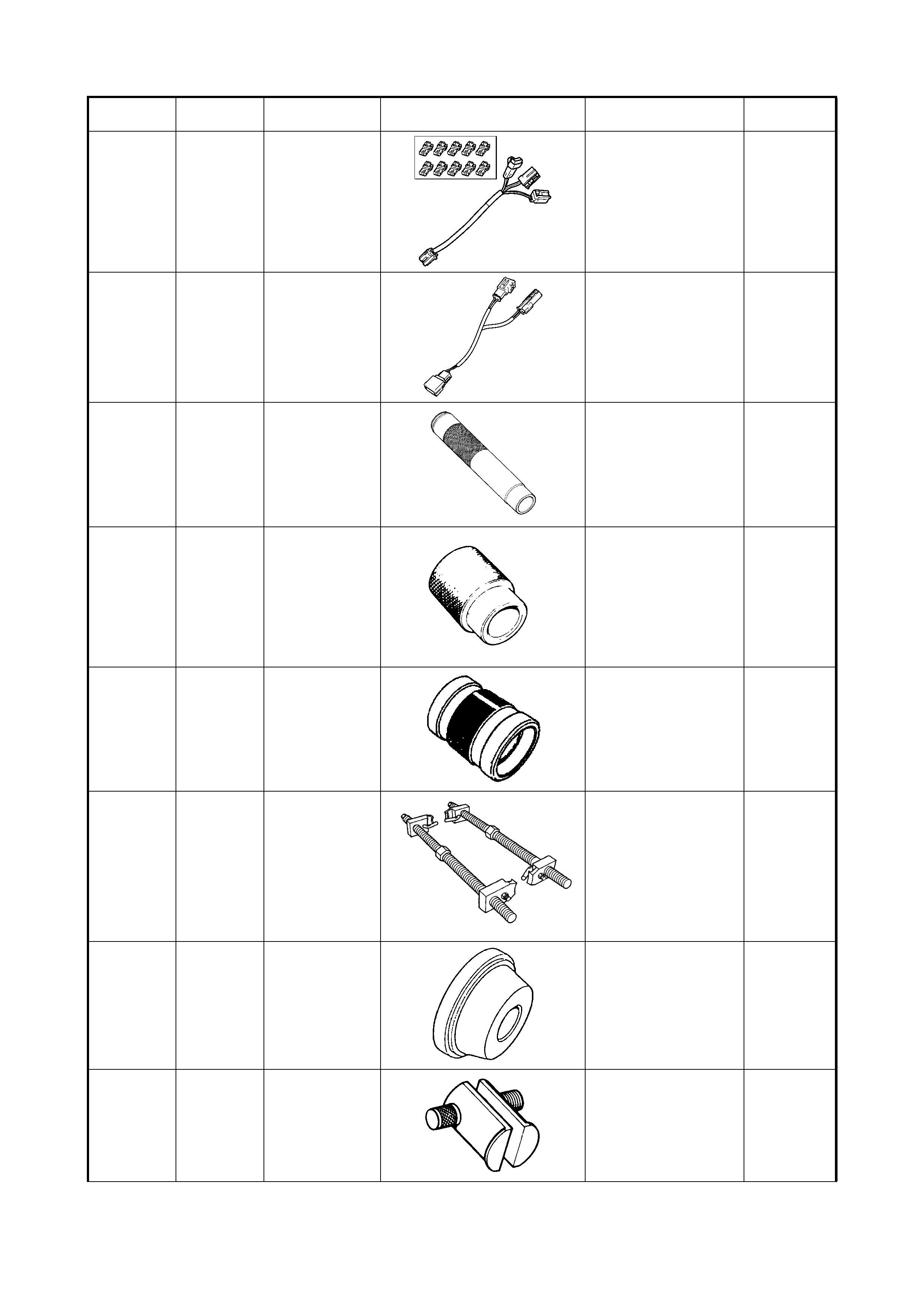
09932-78331 ADAPTER CABLE 10B - AIRBAG SYSTEM
• Airbag deployment Unique
09932-78340 ADAPTER CABLE 10B - AIRBAG SYSTEM
• Diagnosis Mandatory
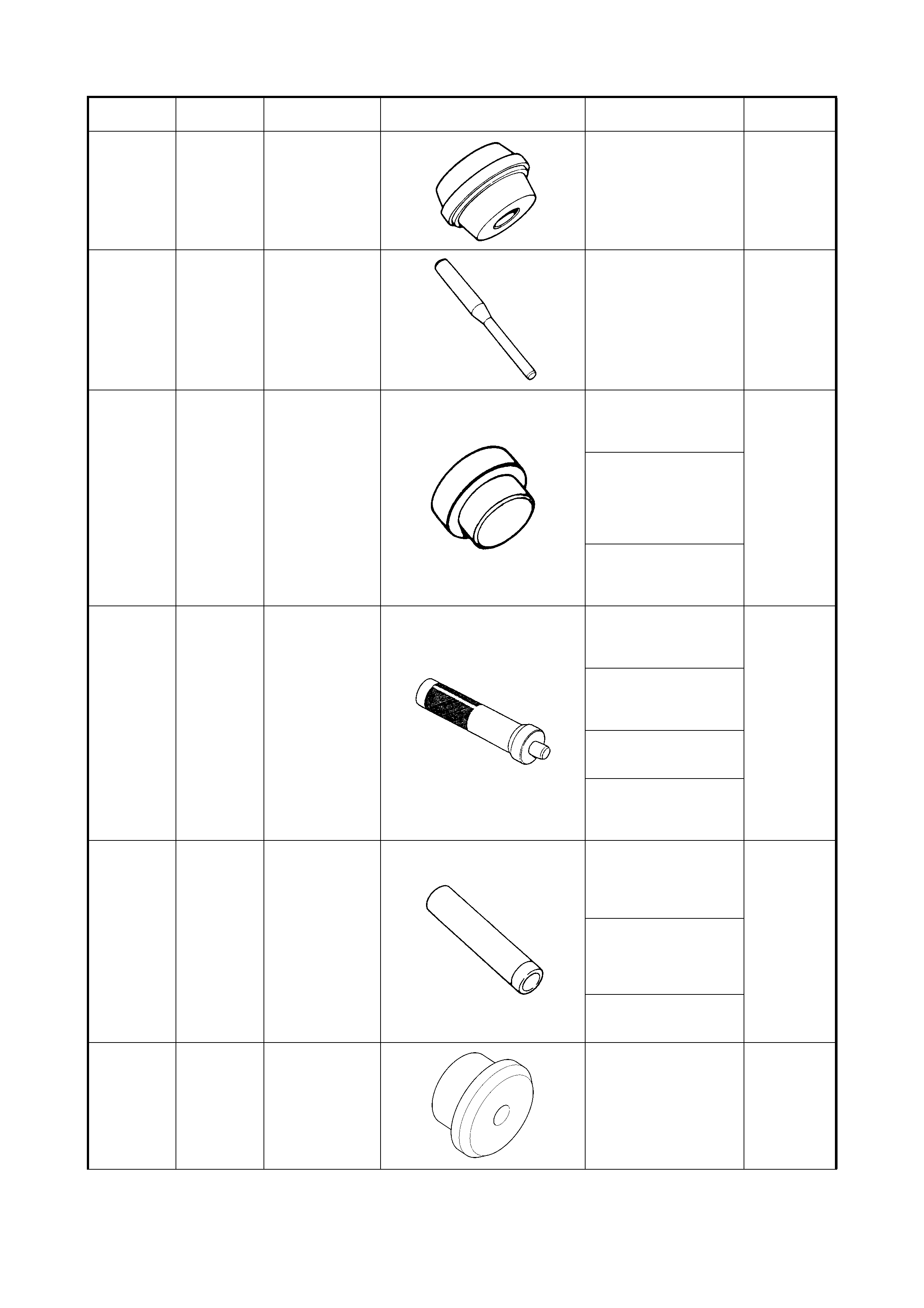
09940-51710 BEARING
INSTALLER 7F - REAR
DIFFERENTIAL
• Rear bearing installation
Unique
09940-53111 BEARING
INSTALLER 7A - MANUAL
TRANSAXLE
• Countershaft low speed
sleeve and hub
assembly installat ion
Unique
09940-54910 SENSOR ROTOR
INSTALLER 7A - AUTOMATIC
TRANSAXLE
• Differential sensor rotor
installation
Unique
09940-71431 6072 OR7294 SPRING
COMPRESSOR 3D - FRONT
SUSPENSION
• Front str ut remova l
Available
09941-34513-
004 BEARING
INSTALLER 7F - REAR
DIFFERENTIAL
• Bevel pinion bearing
outer races installation
Unique
09941-54911 BEARING OU TE R
RACE REMOVER 7D – TRANSFER
• Driven gear bearing
outer race (left and right
case) remo val
Unique
Tool No. Spx
Tool No. Description Illustration Section
Number /usage Category
09941-58020 SOCKET
WRENCH (40mm) 7D – TRANSFER
• Bevel gear retainer
(bevel gear nut removal/
installation)
Unique
09941-64511 BEARING
REMOVER 7A - MANUAL
TRANSAXLE
• Countershaft right
bearing cup removal
Unique
09942-15510 SLIDING
HAMMER 3D - FRONT
SUSPENSION
• Front hub removal
Available
09942-15511 SLIDING
HAMMER 3E - REAR SUSPENSI O N
• Rear brake back plate
and axle shaft removal
Available
7B - AUTOMAT IC
TRANSAXLE
• Countershaft left/right
hand bearing cup
removal
• Differential side left/right
hand bearing cup
removal
09943-17912 FRONT
WHEEL HUB/
REAR BR A KE
DRUM REMOVER
3D - FRONT
SUSPENSION
• Front hub removal
Available
3E - REAR SUSPENSION
• Rear brake back plate
and axle shaft removal
09943-77910 BUSHING
REMOVER 3D - FRONT
SUSPENSION
• Front suspens ion
bushing removal
Unique
09944-18211 PINION TORQUE
CHECKING
SOCKET
3B - MANUAL RACK AND
PINION
• Gear case pinion
bearing installation
Unique
Tool No. Spx
Tool No. Description Illustration Section
Number /usage Category
09944-26011 43mm SOCK ET
(PINION BEARING
PLUG REMOVER)
3B – MANUAL RACK AND
PINION
• Steering pinion bearing
plug removal/installation
Unique
09944-36011 7245 OR
KM210-B STEERING
WHEEL
REMOVER
3C – STEERING WHEE L
& COLUMN
• Steering wheel removal
Mandatory
6A1 – ENGINE
MECHANICAL (M15)
• Crankshaft pulley
removal
09944-67010 OIL SEAL
INSTALLER 3E - REAR SUSPE NSI O N
• Rear axle shaft oil seal
installation
Unique
09944-68210 BEARING
INSTALLER 7B - AUTOMATIC
TRANSAXLE
• Differential side left/right
hand bearing cup
installation
Unique
09944-78210 BEARING
INSTALL ER
SUPPORT
7B - AUTOMAT IC
TRANSAXLE
• Reduct ion drive gear
installation
• Reduct ion drive gear
planetary ring gear
subassembly installation
Unique
09944-88220 OIL SEAL
INSTALLER 7B - AUTOMATIC
TRANSAXLE
• Differential left/right side
oil seal installation
Unique
09944-96011 BEARING OU TE R
RACE REMOVER 7B - AUTOMATIC
TRANSAXLE
• Countershaft left/right
hand bearing cup
removal
• Differential side left/right
hand bearing cup
removal
Unique
09945-16070 RETA IN ER RING
INSTALL ER SET 7D – TRANSFER
• Driven gear bearings
(left and right)
installation
Unique
Tool No. Spx
Tool No. Description Illustration Section
Number /usage Category
09945-26010 SOCKET
WRENCH 17mm 3D - FRONT
SUSPENSION
• Strut nut loosening/
removal/installation
Unique
09946-06710 BEARING
RETA IN ER
DUMMY
7B - AUTOMAT IC
TRANSAXLE
• Transaxle rear cover
snap ring removal
• O/D and 2
nd
coast brake
return spring
subassembly installation
Unique
09950-78220 FLARE NUT
WRENCH (10mm) 5E – ANTILOCK
BRAKING SYSTEM (ABS)
• ABS brake pipe
removal/installation
Available
09950-78230 FLARE NUT
WRENCH (10/
11mm)
5 – BRAKES
• Brake pipe removal/
installation
Available
09951-16060 BUSH REMO VE R 7A - MANUAL
TRANSAXLE
• Differential assembly left
bearing installation
Unique
7F - REAR
DIFFERENTIAL
• Differential side bearings
installation
09951-16090 OIL SEAL
INSTALLER 7F - REAR
DIFFERENTIAL
• Bevel pinion bearing
outer races installation
Unique
09951-18210 OIL SEAL
INSTALLER 3D – FRONT
SUSPENSION
• Front wheel bearing
installation
Unique
7B - AUTOMAT IC
TRANSAXLE
• Reduct ion drive gear
installation
• Reduct ion drive gear
planetary ring gear
subassembly installation
09951-18220 SECONDARY
CUP INSTALLER
SET
5 – BRAKES
• Mast er cylinder
secondary cup
installation
Desirable
09951-76010 BEARING
INSTALLER 7A – MANUAL
TRANSAXLE
• Input shaft oil seal
installation
• Differential assembly
left/right bearing
installation
Unique
7F – REAR
DIFFERENTIAL
• Differential side bearings
installation
Tool No. Spx
Tool No. Description Illustration Section
Number /usage Category
09952-06020 DIAL GAUGE
PLATE No. 2 7B – AUTOMATIC
TRANSAXLE
•1
st
and reverse piston
stroke measurement
• Forward clutch piston
stroke measurement
Unique
09952-16020 BOOSTER
PISTON ROD
ADJUSTMER
5 – BRAKES
• Brake booster
adjustment
Desirable
09952-26020 MASTER
CYLINDER PLUG 5 – BRAKES
• Inspection/testing (Non
ABS Vehicl es)
Desirable
09952-36311 PRESSURE
GAUGE
ATTACHMENT
5 – BRAKES
• Fluid pressure test Desirable
09952-46010 MASTER
CYLINDER
ATTACHMENT
5 – BRAKES
• Inspection/testing Desirable
09952-76011 SNAP RING
PLIERS (CLOSING
TYPE)
7D – TRANSFER
• Intermediate shaft snap
ring installation
Available
09956-02310 FLUID PRESSURE
GAUGE 5 – BRAKES
• Fluid pressure test Unique
09990-06010 MANIFOLD
GAUGE SET 1B - AIR CONDITIONING
• Diagnosis Available
09990-86011 16600 OR
TIFZX-1
(ROBINAIR
NUMBERS)
GAS LEA K
DETECTOR 1B - AIR CONDITIONING
• Diagnosis Available
Tool No. Spx
Tool No. Description Illustration Section
Number /usage Category
09991-06010 MAGNET CLUTCH
PULLEY
INSTALLER
1B - AIR CONDITIONING
• Compressor clutch
pulley installation
Unique
09991-06020 ARMATURE
PLATE SPAN NER 1B - AIR CONDITIONING
• Compressor clutch plate
bolt removal/installation
Unique
09991-06030 ARMATURE
PLATE SPAN NER 1B - AIR CONDITIONING
• Compressor clutch plate
removal/installation
Unique
09991-06040 LIP TYPE SEAL
PROTECTOR 1B - AIR CONDITIONING
• Compres sor clutc h front
cylinder head installation
Unique
09991-06050 LIP TYPE SEAL
INSTALLER 1B - A IR CONDITIONING
• Compres sor clutc h front
cylinder head lip seal
installation
Unique
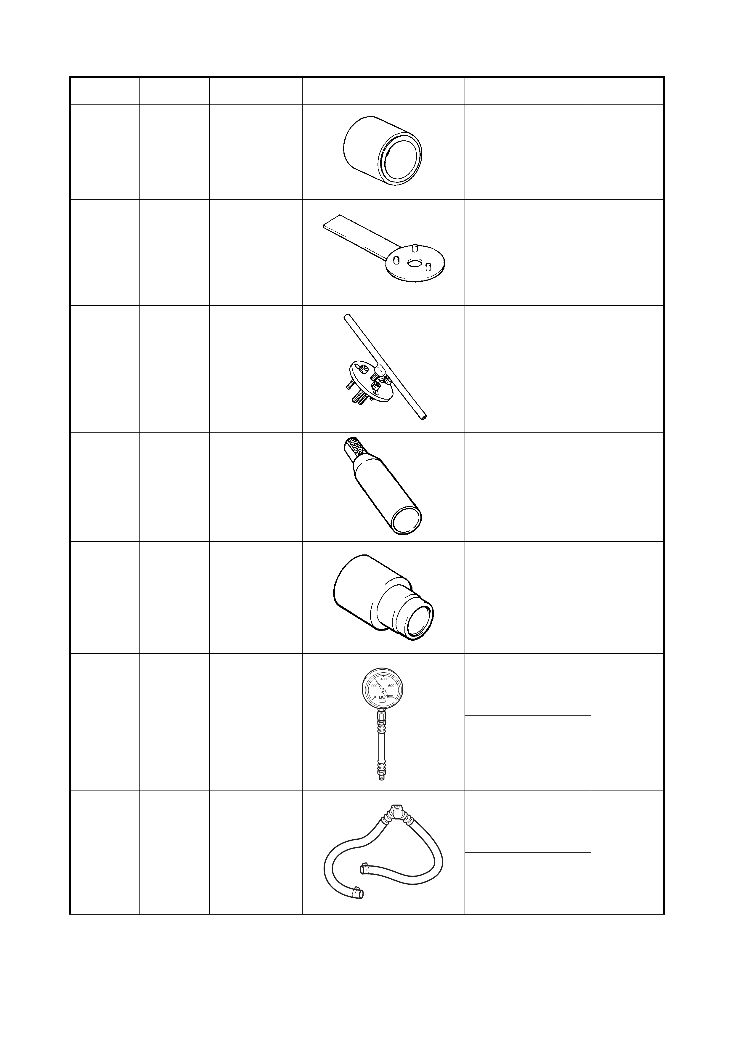
SD28018 or
AU338 -
(Released for
‘V’ and ‘W’
car)
FUEL PR ESS U RE
GAUGE - HIGH
PRESSURE
6 - ENGINE GENE RAL
INFORMATION &
DIAGNOSIS
• Fuel press ure test
Mandatory
6E1 - ENGINE AND
EMISSION CONTROL
SYSTEM
• Fuel press ure test
SD28057 -
(Released for
‘V’ and ‘W’ car
with the quick
connect
release tools
removed)
FUEL PR ESS U RE
GAUGE H OSE 6 - ENGINE GENERAL
INFORMATION &
DIAGNOSIS
• Fuel press ure test
Mandatory
6E1 - ENGINE AND
EMISSION CONTROL
SYSTEM
• Fuel press ure test
Tool No. Spx
Tool No. Description Illustration Section
Number /usage Category
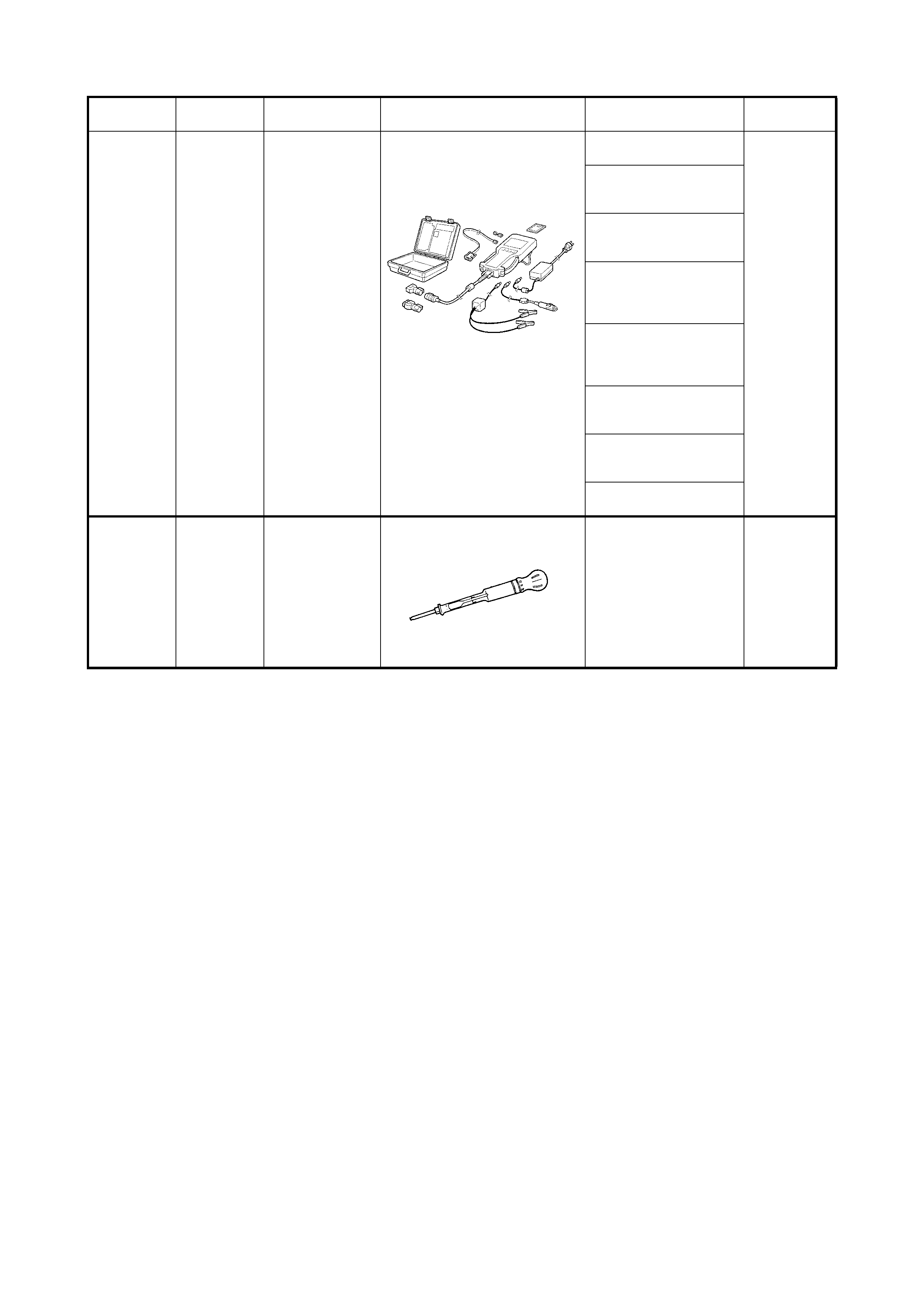
Tech 2 0C – TECH 2
• Diagnosis Mandatory
3B-1 – POWER
STEERING
• Diagnosis
5E – ANTILOCK BRAKE
SYSTEMS
• Diagnosis
6 – ENGINE GENE RAL
INFORMATION &
DIAGNOSIS
• Diagnosis
6E1 – ENGINE EMISSION
AND CONTROL
SYSTE.MS
• Diagnosis
7B – AUTO.MATIC
TRANSAXLE
• Diagnosis
8G – IM .MOB ILISE R
CONTROL SYSTE.M
• Diagnosis
10B – AIRBAG
• Diagnosis
AU505
6B –- ENGINE COOLING
• Testing of coolant
concentration level
Mandatory
Tool No. Spx
Tool No. Description Illustration Section
Number /usage Category