SECTION 0B - MAINTENANCE AND LUBRICATION
1. MAINTENANCE SCHEDULE
1.1 MAINTENANCE SCHEDULE UNDER
NORMAL DRIVING CONDITIONS
1.2 MAINTENANCE RECOMMENDED
UNDER SEVERE DRIVING
CONDITIONS
Severe Condition Code
2. MAINTENANCE SERVICE
2.1 ENGINE
Water Pump / Generator Drive Belt
A/C Compressor Drive Belt
Valve Lash (Clearance)
Engine Oil and Oil Filter
Engine Coolant
Exhaust System
2.2 IGNITION SYSTEM
Spark Plugs
2.3 FUE L SY ST E M
Air Cleaner Filter
Fuel Lines and Connections
Fuel Filter
Fuel Tank
2.4 EMISSION CONTROL SYSTEM
PCV Val ve
Fuel Evaporative Emission Control
System
2.5 BRAKES
Front Brake Discs and Pads
Rear Brake Drums and Shoes
Brake Hoses and Pipes
Brake Fluid
Brake Lever and Cable
2.6 CHASSIS AND BODY
Clutch
Tyres / Wheels
Suspension System
Steering System
Drive Shaft (Axle) Boots /
Propeller Shafts
Manual Transmission Oil
Automatic Transmission Fluid
Transfer Oil & Rear Differential Oil
Latches, Hinges and Locks
3. FINAL INSPECTION
Seats
Seat Belt
Battery Electrolyte Level Check
Accelerator Pedal Operation
Engine Start
Exhaust System Check
Clutch (For Manual Transmission)
Gearshift or Select Lever
Brake
Steering
Engine
Body, Wheels and Power
Train System
Meters and Gauges
Lights
Windshield Defroster
4. RECOMMENDED FLUIDS AND
LUBRICANTS
WARNING:
For vehicles equipped with Supplement Restraint (Airbag) System
• Service on and around the airbag system components or wiring must be performed only by an
authorised H OLDEN retailer. Refer to Section 10B AIRBAG SY STEM COMP ONENTS AN D W IRING
LOCATION V IEW in GENERAL DESCRIPTION in order to confirm whether you are performing ser-
vice on or near the airbag system components or wiring. Please observe all W ARNINGS and SER-
VICE PRECAUTIONS, refer to Section 10B ON-VEHICLE SER VICE before perf orming service on or
around the airbag system components or wiring. Failure to follow WARNINGS could result in
unintentional activation of the system or could re nder the system inoperative. Either or these two
conditions may result in severe injury.
• Technical service work must not be started for at least 90 seconds after the ignition switch is
turned to the “LOCK” position and the negative cable is disconnected from the battery. Other-
wise, the system may be activated by reserve energy in the Sensing and Diagnostic Module
(SDM)
Techline
1. MAINTENANCE SCHEDULE
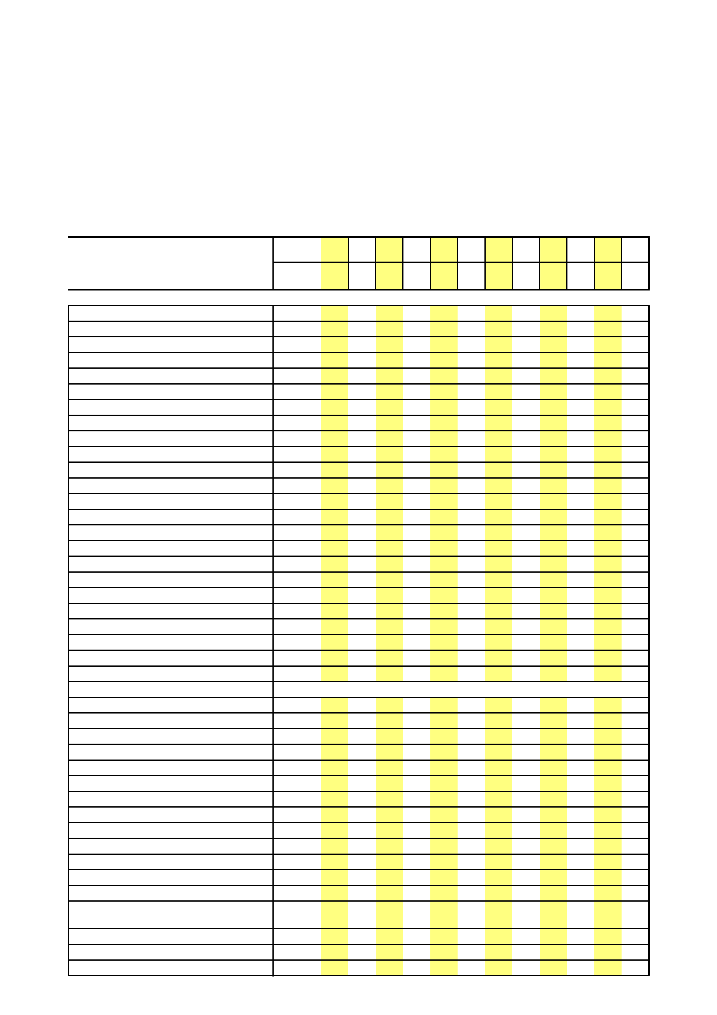
1.1 MAIN TENANCE SCHEDULE UNDER NORMAL DRIVING CONDITIONS
NOTE:
• This interval should be judged by the odometer reading or months, whichever comes first.
Use odometer readings or years, which ever
occurs first.
x1000k
m15 30 45 60 75 90 105 120 135 150 165 180
or
years
12345678910 11 12
Engine oil RRRRRRRRRRRR
Engine oil filter R R R R R R
Fuel filter R R
Fuel Emission System Check I I
PCV Valve Check I I
Air cleaner element I I R I I R I I R I I R
Coolant Level & % Concentration Check II II IIIII
Coola nt - Replac e R R R R
Access ory Drive Belt IIIIIRIIIIIR
Spark plugs R R R R
Valv e clearances A A A A A A
Brake Fluid Level - Inspect IIIIIIIIIIII
Brake Fluid - Change Change every two years (regardless of km)
Automat ic Transmis sio n - Fluid Lev el IIIIII
Automat ic Transm issio n F lui d R
Automatic Transmission Cooler Hoses I I I
Manual Transmission Oil I R R R R
Transfer Case Oil Lev el IIIIII
Rear Differential Oil R I I I I I
Oil/Fl uid Leak s - V isual Ch eck Of Engine
& Transmission IIIIIIIIIIII
Front Brakes - Check Pad Thickness IIIIIIIIIIII
I: Inspect and correct or replace as necessary
R: Replace or change
T: Tighten to specified torque
L: Lubricate
A: Adjust
Under extreme conditions, more frequent maintenance is required. Refer to “1.2 MAINTENANCE RECOMMENDED
UNDER SEVERE DRIVING CONDITIONS” in this Section.
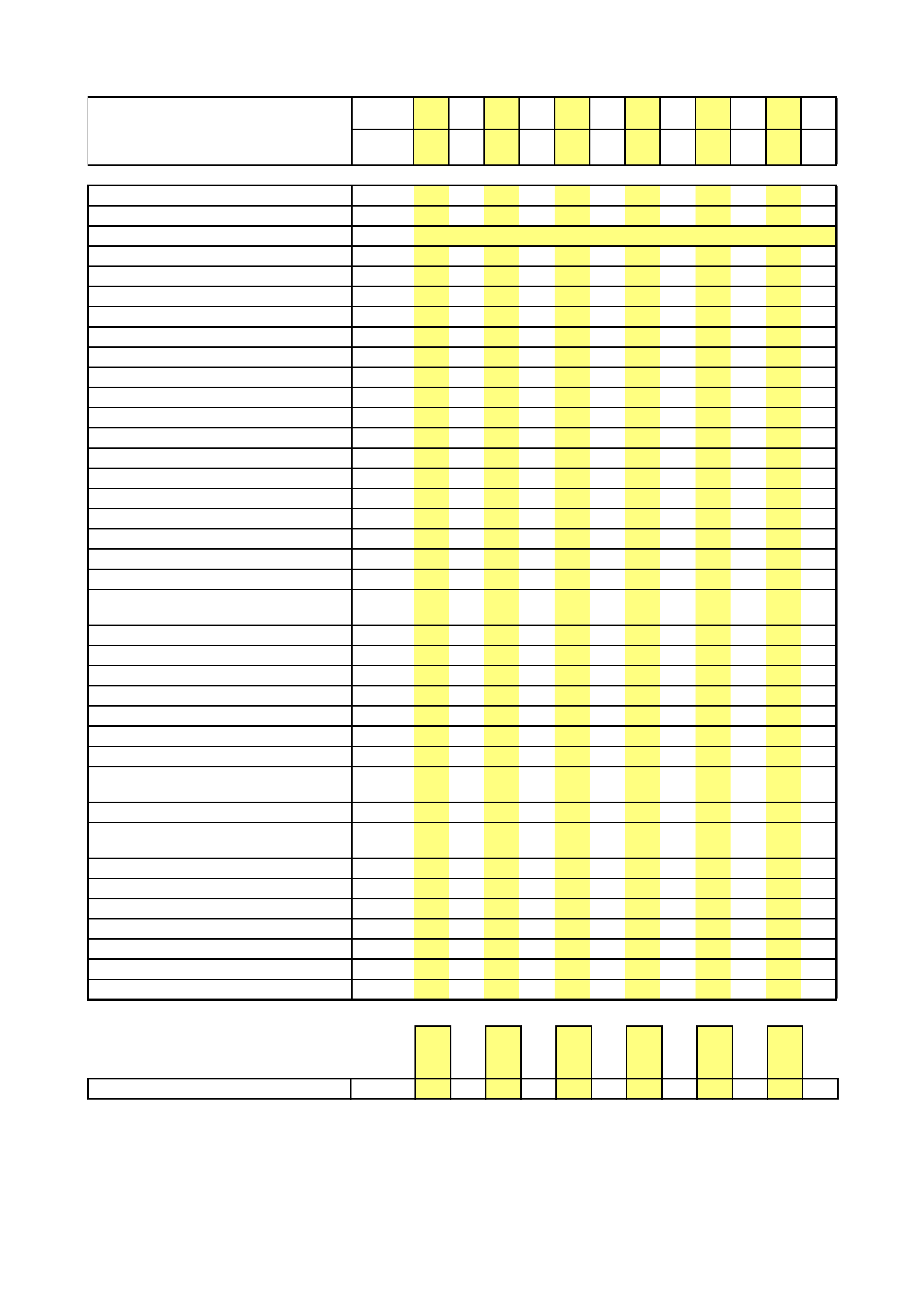
Rear Brakes - Check Drums & Shoes IIIIII
Park Brake - Lever & Cable Adjustment First 15000km Service Only
Brake Pipes & Hoses - Visual Check IIIIII
Exhaust System - Check IIIIII
Fuel Lines & Fuel Tank IIIIII
Suspension System IIIIII
Drive Shaft/Axle Rubber Boots I I I I
St eering Sys tem - Check IIIIII
Wheel Nuts TTTTTTTTTTTT
Tyres - Check Condition & Pressure IIIIIIIIIIII
Headlamps, Rear Lamps, Turn Signals,
St op Lamps - Che c k IIIIIIIIIIII
Warning Lamps & Instruments IIIIIIIIIIII
Windscreen Washers & Wipers IIIIIIIIIIII
Clutch Pedal - Pedal Height & Travel IIIIII
Body & Unde rbody - Check Corrosion
Protection IIIIIIIIIIII
Door, Bonnet, Tailgate Hinges & Locks -
Check IIIIII
Door, Bonnet, Tailgate Hinges & Locks LLLLLL
Keyless Entry System Battery - Replace IIIIII
IIIIIIIIIIII
Road Te st
Use odometer readings or years, which ever
occurs first.
x1000k
m15 30 45 60 75 90 105 120 135 150 165 180
or
years
12345678910 11 12
SERVICE TIMES
11.91.5 1.9 12.51.6 1.9 1.5 1.5 1.6 2.7
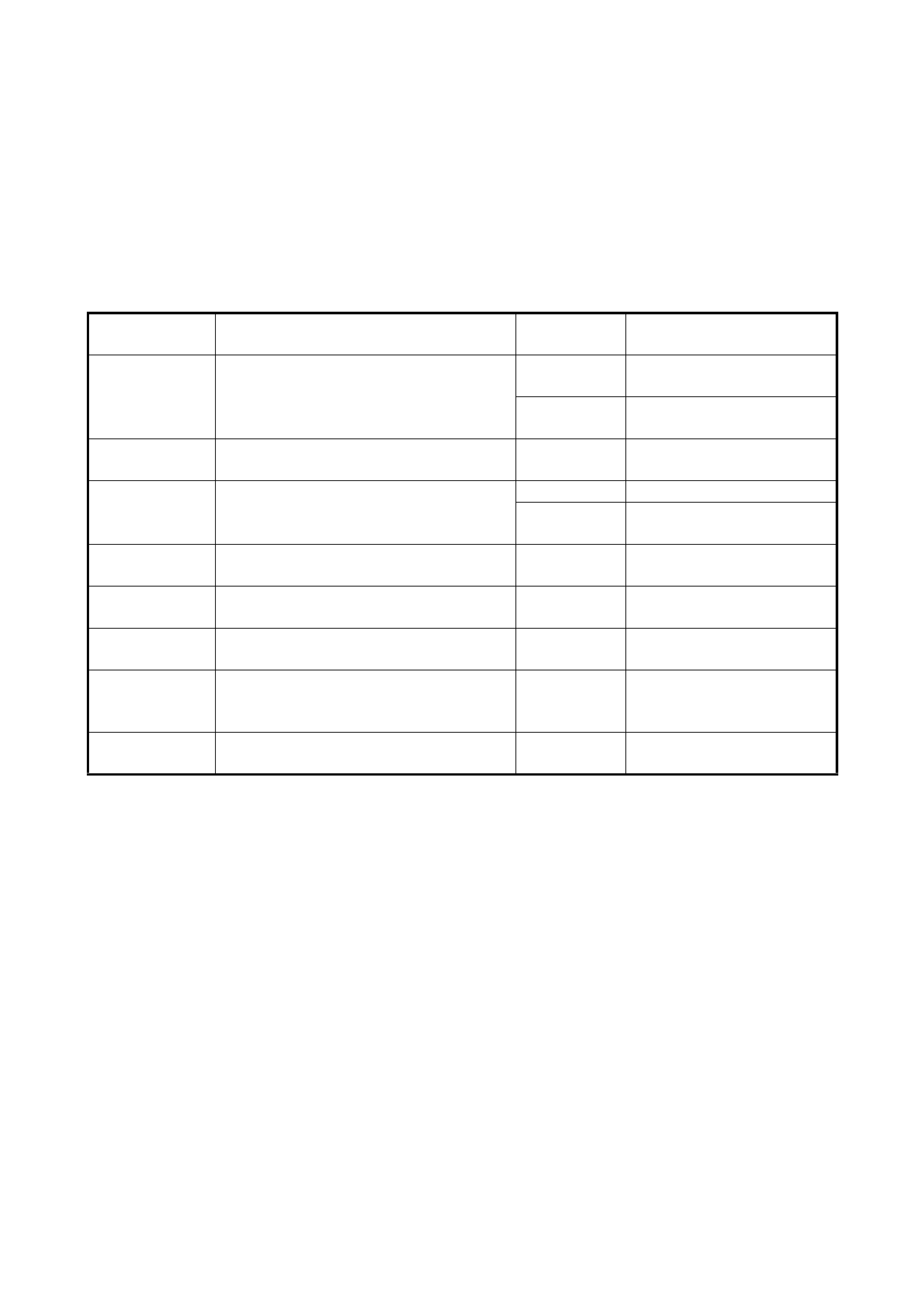
1.2 MAINTENAN CE RECOMMENDED UNDER SEVERE DRIVING CONDITIONS
If the vehicle is usually used under any of the severe condition codes given below, it is recommended that the
applicable maintenance operation be performed at the interval shown in the following table.
SEVERE CONDITION CODE
A: Repeated short trips
B: Driving on rough and/or muddy roads
C: Driving on dusty roads
D: Driving in extremely cold weather and/or salted roads
E: Repeated short trips in extremely cold weather
F: Towing a trailer
NOTE:
• I: Inspect and correct or replace if necessary
• R: Replace or change
•✱1: Inspect more frequently if the vehicle is used under dusty conditions.
Severe
Condition Code Maintenance Maintenance
Operation Maintenance Interval
– B C D – – Drive belt I Every 15,000 km
or 12 months
R Every 45,000 km
or 36 months
A – C D E F Engine oil and oil filter R Every 5,000 km
or 4 months
– – C – – – Air cleaner filter ✱1 I Every 2,500 km
R Every 30,000 km
or 24 months
A B C – E F Spark plugs R Every 10,000 km
or 8 months
– B C D – F Wheel bearings I Every 15,000 km
or 12 months
– B – D E F Drive shafts and propeller shafts I Every 15,000 km
or 12 months
– B – – E F Manual transmission, transfer and
differential oil R At 15,000 km or 12 months
then every 30,000 km or
24 months
– B – – E F Automatic transmission fluid R Every 30,000 km
or 24 months
2. MAINTENANCE SERVICE
2.1 ENGINE
WARNING:
All inspection and replacement is to be
performed with ENGINE NOT RUNNING.
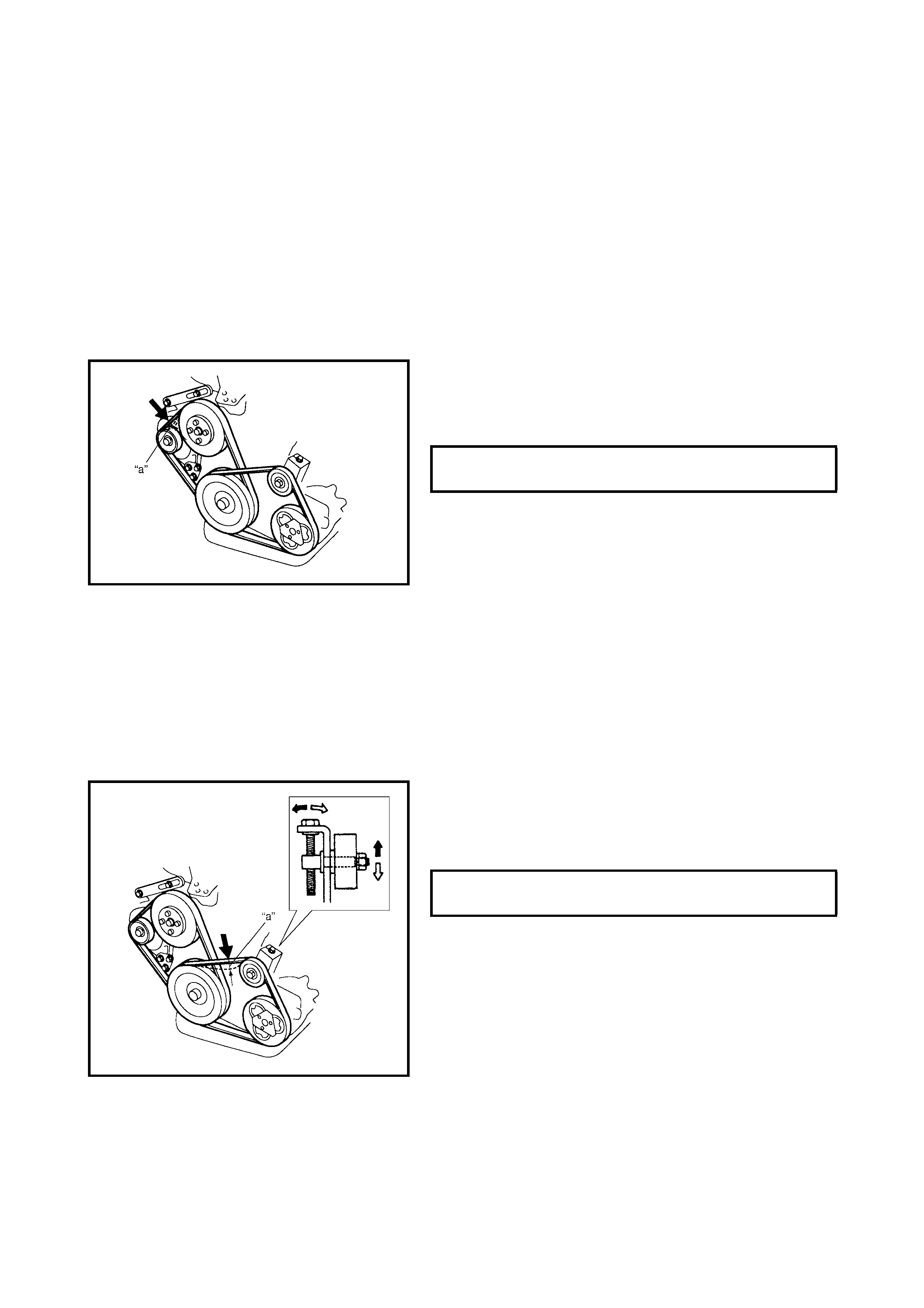
WATER PUMP / GENERATOR DRIVE BELT
Inspection
1. Disconnect negative (–) cable at battery.
2. Inspect the belt for cracks, cuts, deformation, wear and
cleanliness. If any defect exists, replace the belt.
3. Check the belt for tension by measuring the deflection
under thumb pressure.
NOTE:
When installing a new belt, adjust belt tension to
a deflection of 3 - 4 mm.
4. If the belt is too tight or too loose, adjust it to specifica-
tion by adjusting the alternator position.
5. Tighten the alternator adjusting bolts and pivot bolt.
6. Connect negative (–) cable to battery.
Replacement
Refer to Section 6B, 4.9 WATER PUMP / GENERATOR
DRIVE BELT.
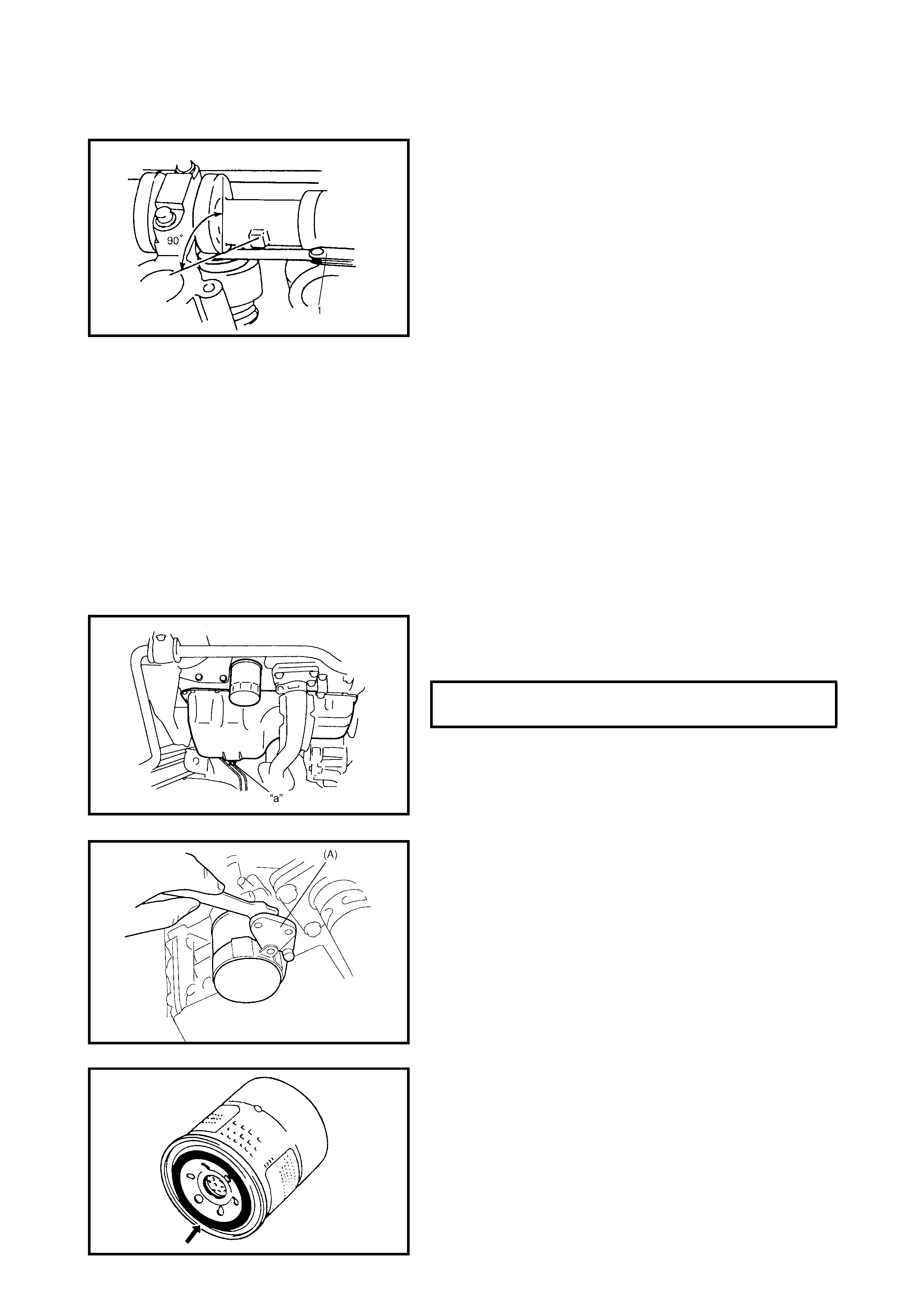
A/C COMPRESSOR DRIVE BELT
Inspection
1. Disconnect negative (–) cable at battery.
2. Inspect the belt for cracks, cuts, deformation, wear and
cleanliness. If any defect exists, replace the belt.
3. Check the belt for tension by measuring the deflection
under thumb pressure.
4. If the belt tension is out of specification, adjust it, refer
to Section 1B, 2.5 COMPRESSOR DRIVE BELT.
5. Connect negative (–) cable to battery.
Replacement
Refer to Section 1B, 2.5 COMPRESSOR DRIVE BELT.
WATER PUMP / GENERATOR DRIVE
BELT DEFLECTION (a:) 4.5 –- 5.5 mm @
10 kg pressure
A/C COMMPRESSOR DRIVE BELT
DEFLECTION (a:) 3 –- 5 mm @ 10
kg pressure
VALVE LASH (CLEARANCE)
Inspection
1. Inspect the intake and exhaust valve lash with a
thickness gauge (1). Adjust as necessary, refer to
Section 6A1, 2.5 VALVE LASH.
ENGINE OIL AND OIL FILTER
Replacement
WARNING:
• New and used engine oil can be hazardous.
Read WARNING in General Precaution in
Section 0A and observe what in written there.
• Ste p 1 - 7 described below must be performed with
the ENGINE NOT RUNNING. For Step 8, have ade-
quate ventilation while the engine is running.
Before draining the engine oil, check the engine for oil leak-
age. If any evidence of leakage is found, make sure to
repair the defe ctive part before procee ding to the following
work.
1. Drain engine oil by removing drain plug.
2. After drainin g o il, wipe drain plug c lean. R einstall drain
plug, and tighten it securely as specified.
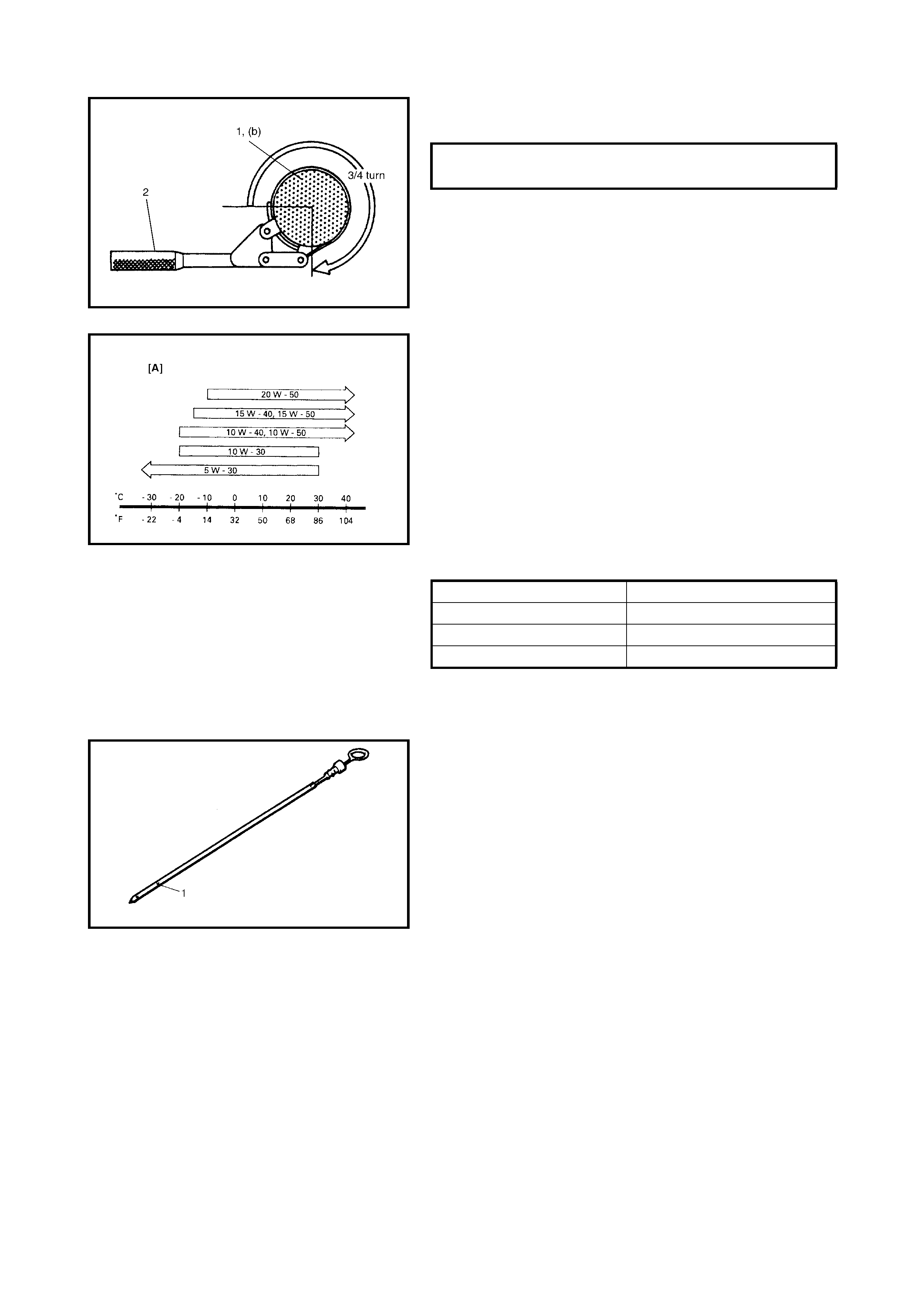
3. Loosen the oil filter with an oil filter wrench, special tool
09915-473 30 (A) .
NOTE:
Before fitting a new oil filter, apply a thin film of
engine oil to its O-ring.
4. Screw a new filter on the oil filter stand by hand until
the filter O-ring con tacts the mountin g surfac e.
NOTE:
To tighten the oil filter properly, it is important to
accurately identify the position at which filter O-ring first
contacts the mounting surface.
ENGINE OIL DRAIN PLUG TORQUE
SPECIFICATION (a) 50 Nm
5. Tighten the filter (1) 3/4 turn from the point of contact
with the mounting surface using an oil filter wrench (2).
6. Replenish the engine with oil until the level is brought
to the FULL mark on the dipstick. (oil pan and oil filter
capacity). The filler inlet is at the top of the cylinder
head cover.
It is recommended to use engine oil of ACEA service
classification A2 or A3 viscosity grade 10W-30. Select
the appropriate oil viscosity according to the proper
engine oil viscosity chart [A].
Engine Oil Capacity
NOTE:
The amount of oil required may differ from the
data in the table due to temperat ure, viscosity, etc.
7. Check oil filter and drain plug for oil leakage.
8. Start the engine and run it for 3 minutes. Stop it and
wait 5 minutes before checking the oil level. Add oil, as
necessary, to bring oil level to FULL level mark (1) on
the dipstick.
OIL FILTER TORQUE SPECIFICATION
(b) (ref) 14 Nm
Oil pan capacity Approx. 3.6 litres
Oil filter capacity Approx. 0.2 litre
Others Approx. 0.3 litre
Total Approx. 4.1 litres
ENGINE COOLANT
Replacement
WARNING:
To avoid danger of being burned, do not
remove the radiator cap while the engine and
radiator are still hot. Scalding fluid and steam can
be blown out under pressure if cap is taken off too
soon
CAUTION: Always use the recommended coolant, refer
to 4. RECOMMENDED FLUIDS AND LUBRICANTS in
this Section. Other coolants may be incompatible and
may adversely affect the cooling system.
As a minimum, when changing engine coolant, use a
mixture of 70% water and 30% Holden Cruze coolant,
part number 92145591 where the ambient temperature
will not fall lower than -16°C. This mixture ratio will
also provide corrosion protection and lubrication.
If it is possible for the ambient temperature to fall
below -16°C, a 50% water and 50% Holden Cruze
coolant should be used.
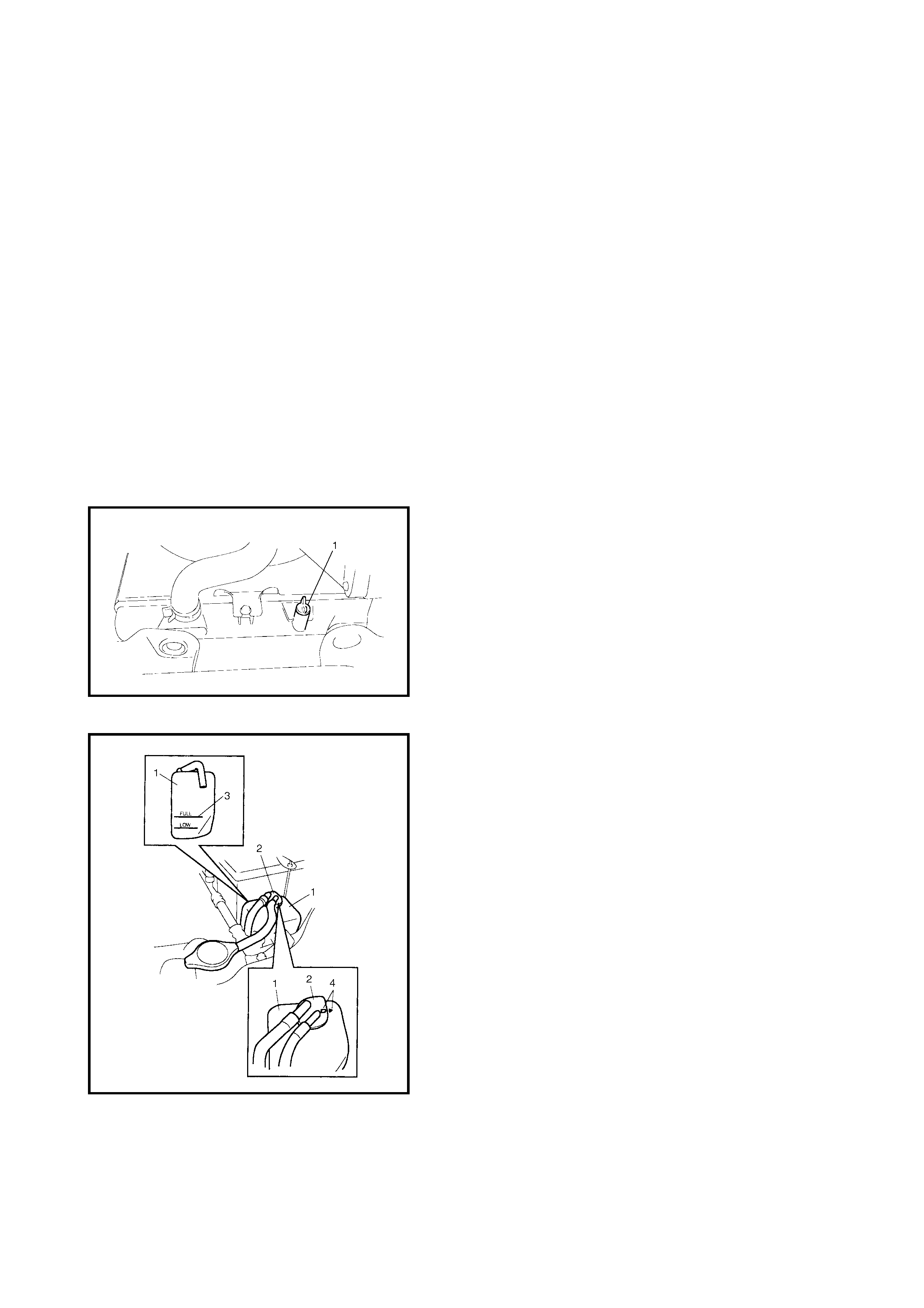
1. Remove the radiator cap when engine is cool.
2. Loosen the radiator drain plug (1) to drain the coolant.
3. Remove the reservoir and drain.
4. Tighten the plug securely and reinstall the reservoir.
5. Fill the radiator with the specified amount of coolant,
and run the engine for 2 or 3 minutes at idle.
This drives out any air which may still be trapped within
the cooling sy st em.
6. Stop the engine.
7. Add coolan t as required until the cool ant level reac hes
the filler throat of the radiator.
8. Reinstall the radiator cap.
9. Add coolant to the reservoir (1) so that its level aligns
with the FULL mark (3).
10. Reinstall the cap (2), aligning the arrow marks (4) on
reservoir and cap.
EXHAUST SYSTEM
Inspection
WARNING:
To avoid danger of being burned, do not
touch the exhaust system when it is still hot. Any
service on exhaust system should be performed
when it is cool.
When performing periodic maintenance, or the vehicle is
raised for other service, check exhaust system as follows:
• Check the rubber mountings for damage, deterioration,
and incorrect position.
• Check the exhaust system for leakage, loose connec-
tions, dents and damages.
If bolts or nuts are loose, tighten them to specification.
• Check nearby body areas for damaged, missing, or
incorrectly positioned parts, open seams, holes, loose
connections or other defects which could permit
exhaust fumes to seep into the vehicle.
• Ensure that exhaust system components have enough
clearance from the underbody to avoid overheating
and possible damage to the floor carpet.
• Any defects should be fixed at once.
2.2 IGNITION SYSTEM
SPARK PLUGS
Replacement
Replace spark plugs with new ones, refer to Section 6F1,
3.3 SPARK PLUGS.
2.3 FUEL SYSTEM
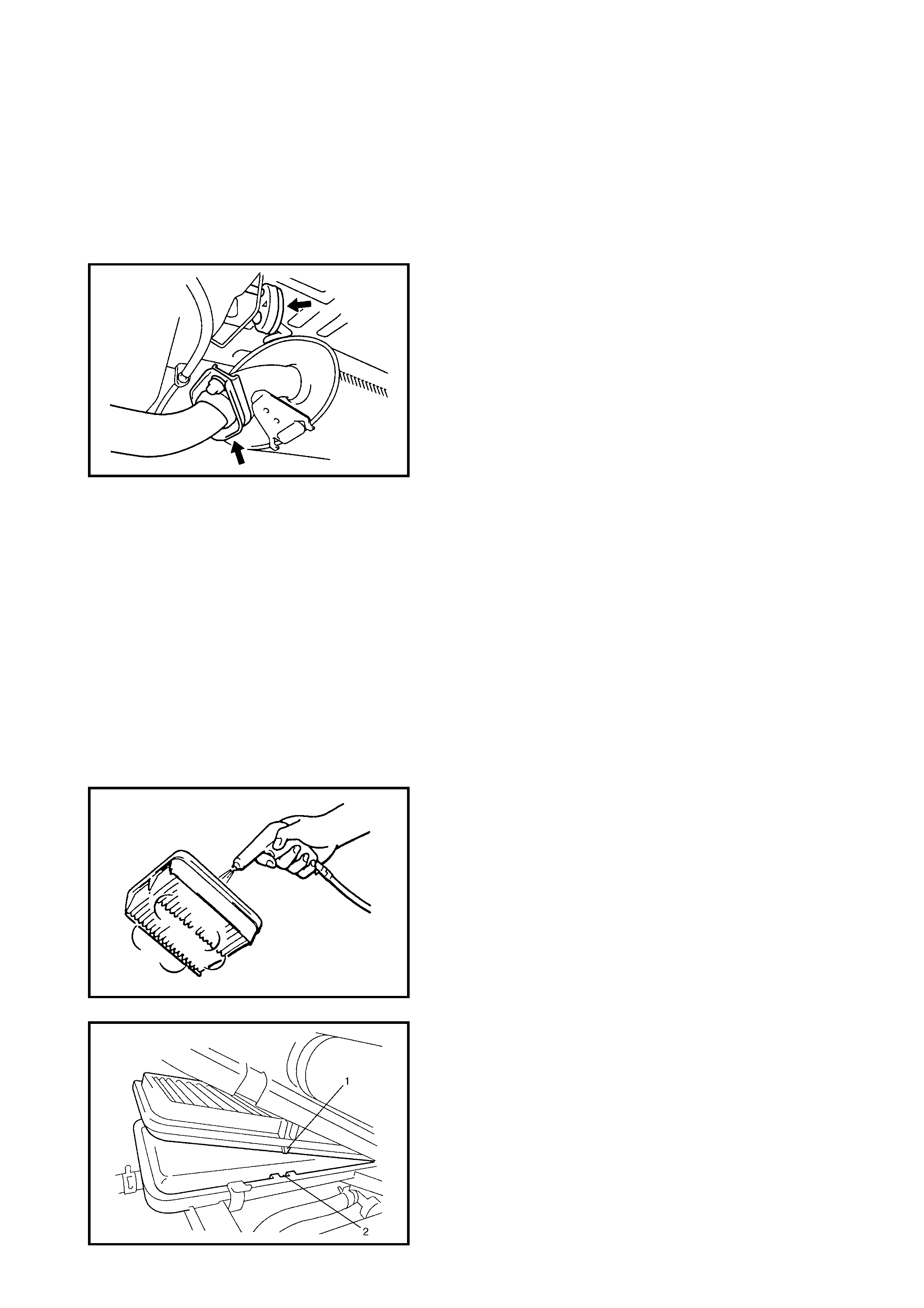
AIR CLEANER FILTER
Inspection
1. Remove the air cleaner case clamps.
2. Ta ke the air cle ane r filter out of the case.
3. Check that the filter is not excessively dirty, damaged
or oily. Clean the filter with compressed air from the air-
outlet side of the filter.
4. Install the air c leane r filter, fi tting th e protrus ion (1) in to
the groove (2) of the case.
5. Clamp the upper case securely.
Replacement
Replace the air cleaner filter with new one as described in
Steps 1., 2. and 4. of INSPECTION.
FUEL LINES AND CONNECTIONS
Inspection
Visually inspect the fuel lines and connections for evidence
of fuel leakage, hose cracking and damage.
Make sure all clamps are secure.
Repair leaky joints, if any.
Replace hoses that are suspected of being cracked.
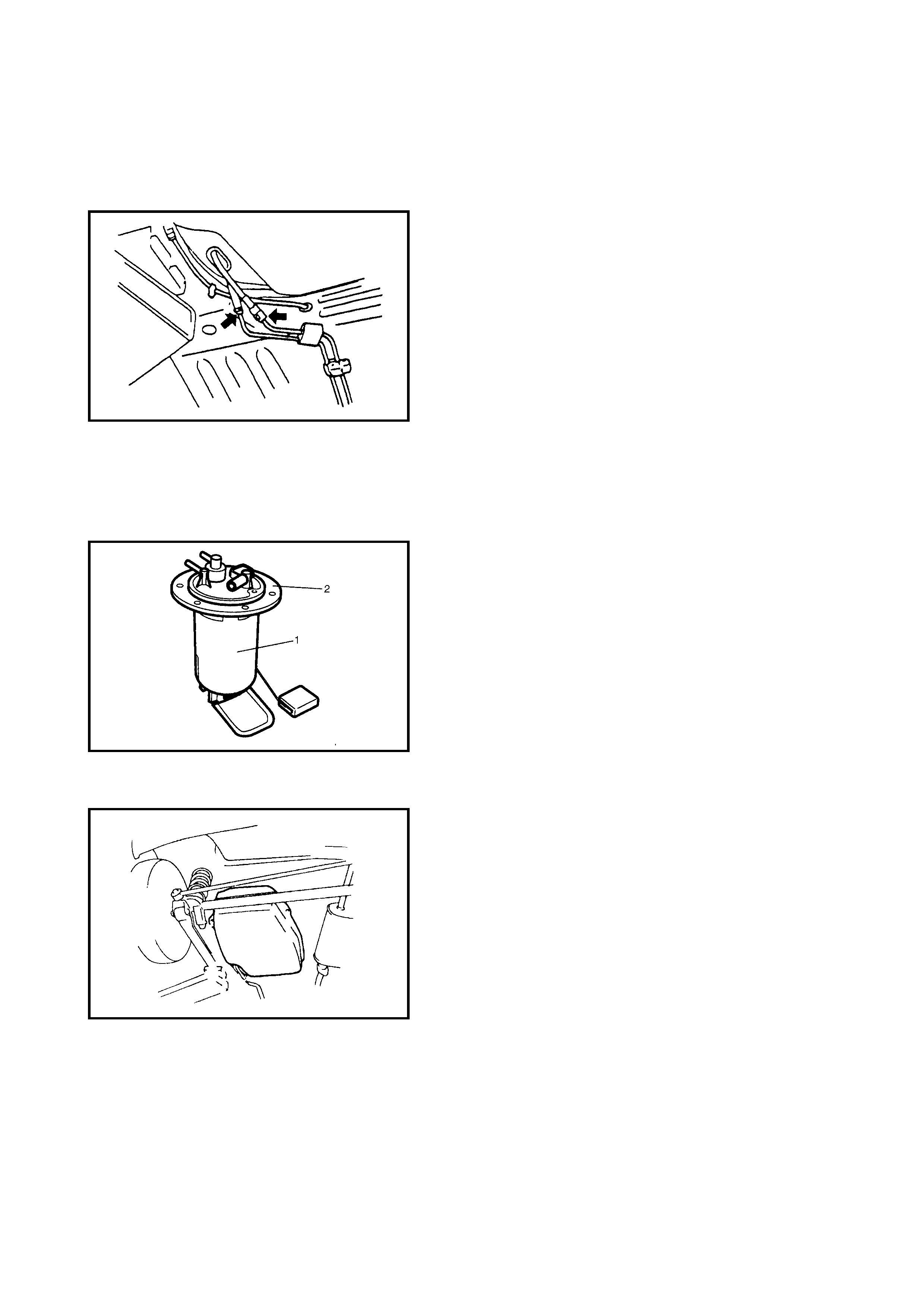
FUEL FILTER
Replacement
WARNING:
This work must be performed in a well
ventilated area and away from any open flames
(such as gas hot water heaters).
The fuel filter (1) is installed in the fuel pump assembly (2)
which is installed in the fuel tank.
Replace the fuel filter with new one, refer to Section 6C,
2.8 FUEL PUMP ASSEMBLY.
FUEL TANK
Inspection
Check the fuel tank for damage, cracks, fuel leakage,
corrosion and the tank bolts for looseness.
If a problem is found, repair or replace.
2.4 EMISSION CONTROL SYSTEM
PCV VALVE
Inspection
Check the crankcase ventilation hose and PCV hose for
leaks, cracks or blockage.
Check the PCV valve for sticking or blockage, refer to
Section 6E1, 2.4 EMISSION CONTROL SYSTEM.
FUEL EVAPORATIVE EMISSION CONTROL
SYSTEM
Inspection
1. Visually inspect the hoses for cracks, damage, or
excessive bends. Inspect all clamps for damage and
correct position.
2. Check the EVAP canister for operation and blockage,
refer to Section 6E1, 2.4 EMISSION CONTROL
SYSTEM.
If a malfunction is found, repair or replace.
2.5 BRAKES
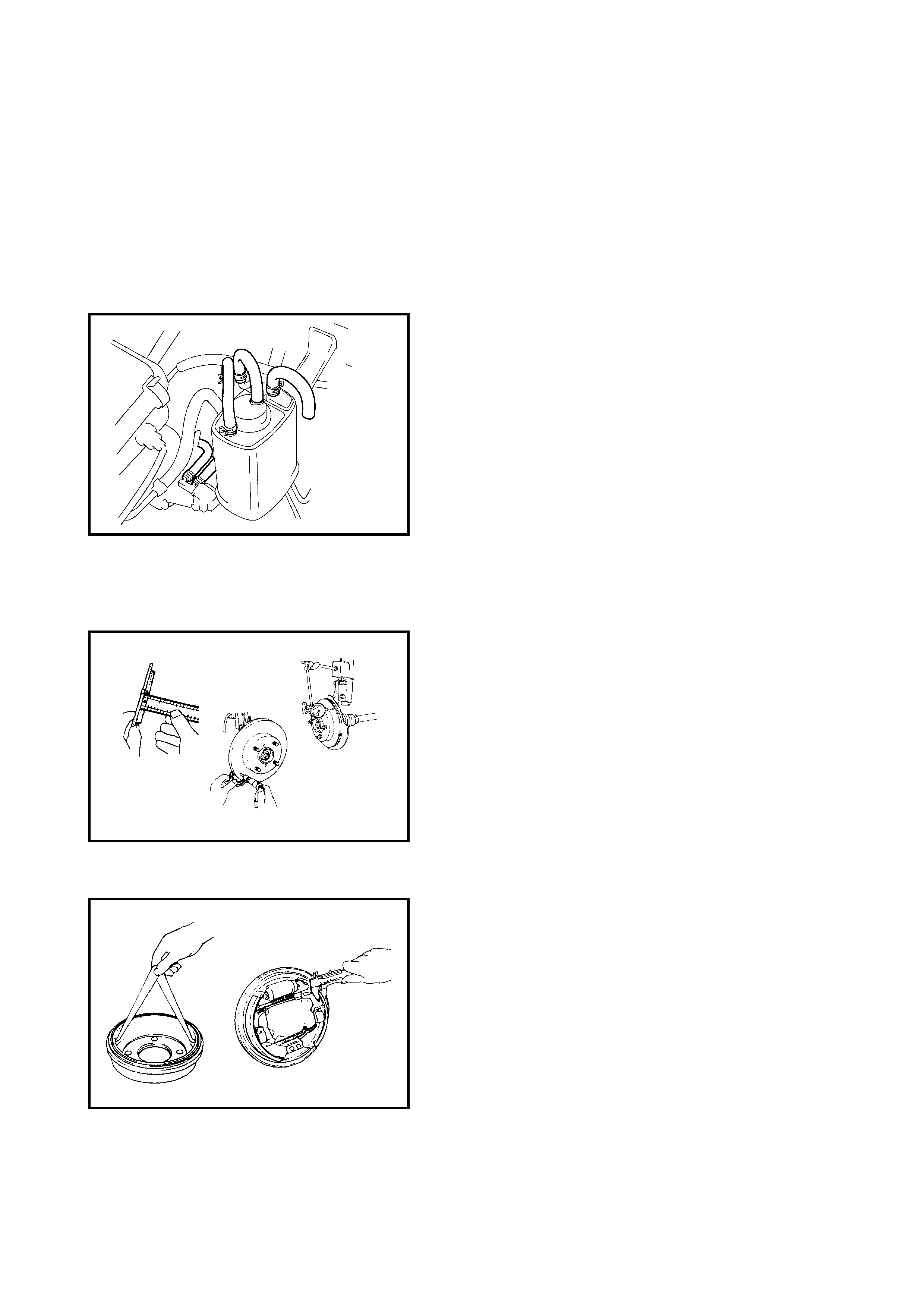
FRONT BRAKE DISCS AND PADS
Inspection
1. Remove the wheel and caliper but don’t disconnect
brake hose from caliper.
2. Check the front disc pads and discs for excessive
wear, damage and deflection. Replace parts as neces-
sary, refer to Section 5, 3.2 FRONT BRAKE.
NOTE: Torque the caliper pin bolts to specification.
REAR BRAKE DRUMS AND SHOES
Inspection
1. Remove the wheel and brake drum.
2. Check the rear brake drums and brake linings for
excessive wear and damage. Also check the wheel
cylinders for leaks. Replace parts as necessary, refer
to Section 5, 3.3 REAR BRAKE.
BRAKE HOSES AND PIPES
Inspection
Perform this inspection where there is enough light and use
a mirror as necessary.
• Check the brake hoses and pipes for correct mounting,
leaks, cracks, chafing and other damage.
• Check that the hoses and pipes are clear of sharp
edges and moving parts.
Repair or replace any of these parts as necessary.
CAUTION:
After replacing any brake pipe or hose,
bleed air from the brake system, refer to Section 5,
3.1 AIR BLEEDING OF BRAKE SYSTEM.
BRAKE FLUID
Replacement
Drain the existing fluid from the brake system completely
and fill with the specified fluid.
Bleed air from the system, refer to Section 5,
3.1 AIR BLEEDING OF BRAKE SYSTEM.
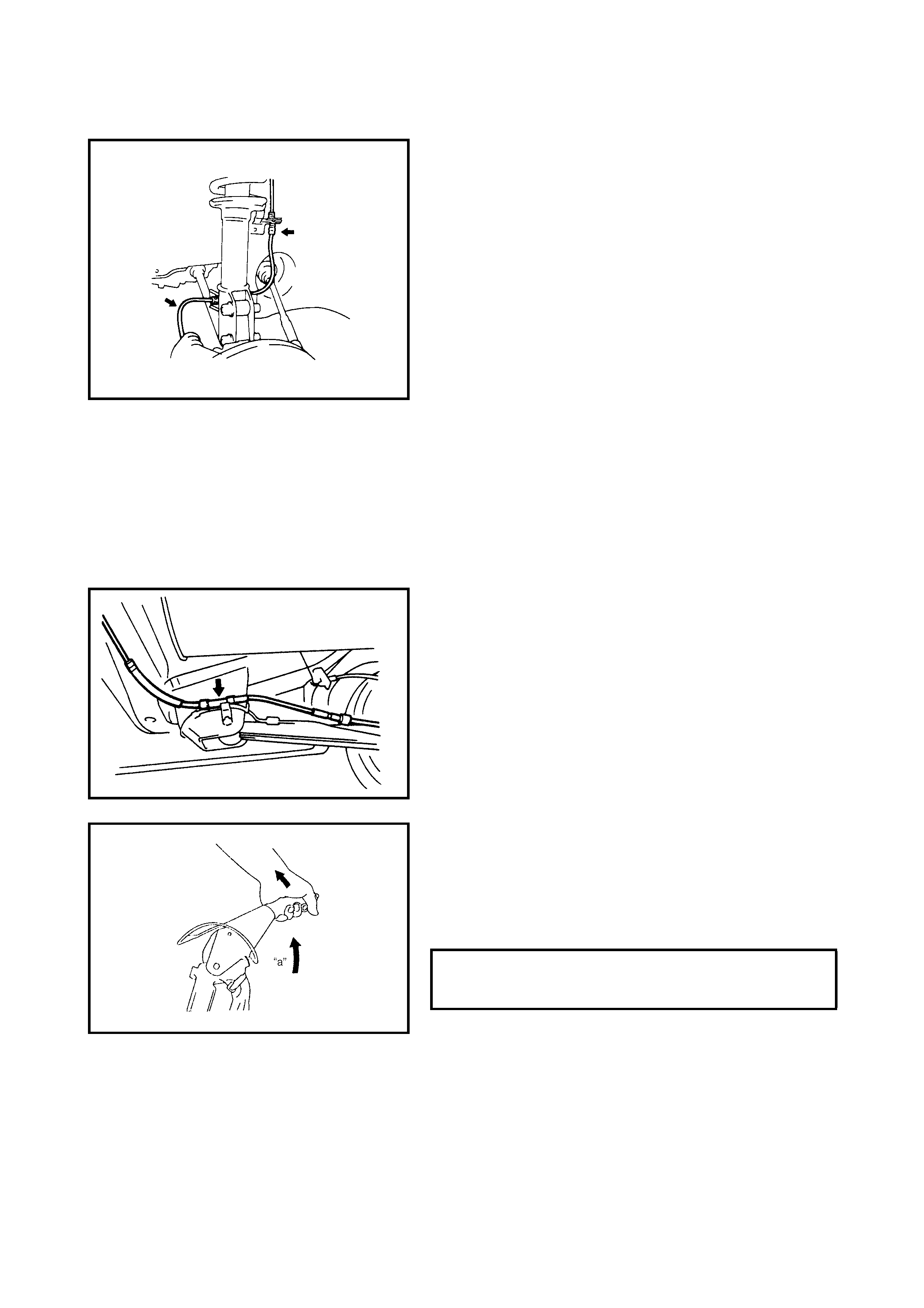
BRAKE LEVER AND CABLE
Inspection
1. Inspect the brake cable for damage and smooth
movement.
Replace the cable if it is in deteriorated condition.
2. Check the tip of each tooth for damage or wear. If any
damage or wear is found, replace the parking lever.
3. Check the parking brake lever for proper operation and
stroke, and adjust it if necessary, refer to
2.10 PARKING BRAKE INSPECTION AND
ADJUSTMENT in Section 5.
PARKING BRAKE STROKE (WHEN
LEVER IS PULLED UP AT 200 N) (20
kg) 4 T O 9 NOTCHES
2.6 CHASSIS AND BODY
CLUTCH
Inspection
Check the clutch pedal for height and free travel (1), refer
to Section 7C, 3.2 CLUTCH PEDAL AND CLUTCH PEDAL
BRACKET. Adjust or correct if necessary.
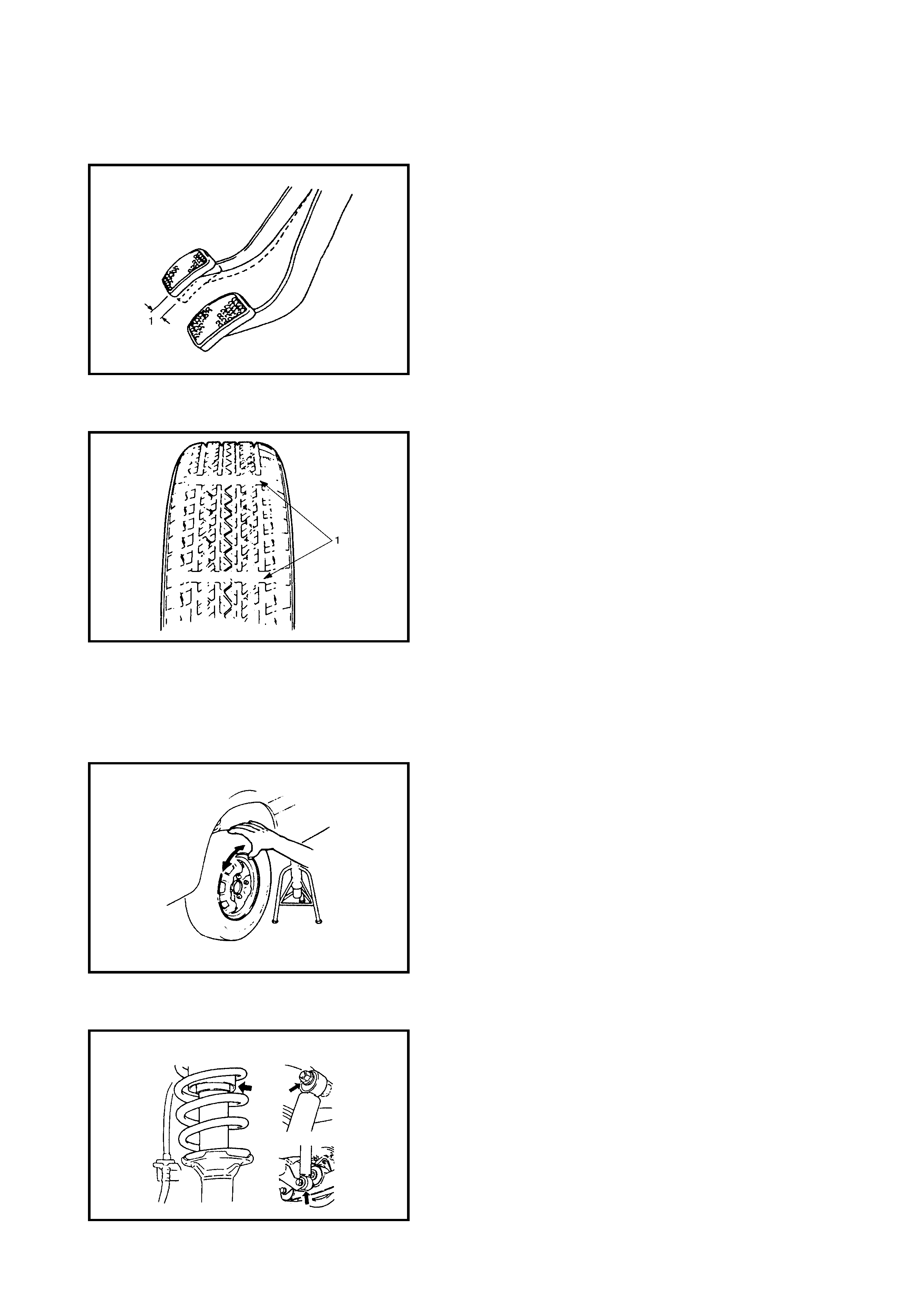
TYRES / WHEELS
Tyre Inspection
1. Check the tyres for uneven or excessive wear, or
damage.
If defective or worn to the wear indicators (1), replace,
refer to 1.2 TYRE DIAGNOSIS in Section 3 for details.
2. Check the inflation pressure of each tyre and adjust to
specification as necessary.
NOTE: Tyre inflation pressure should be checked when the
tyres are cool. Refer to the vehicle’s tyre placard located on
the right-hand door lock pillar or in the owner’s manual for
specifications.
3. Rotate the tyres, refer to Section 3F,
3.2 TYRE MAINTENANCE.
Wheel Inspection
Inspect each wheel rim for dents, distortion and cracks. A
disc in badly damaged condition must be replaced.
Wheel Bearing Inspection
1. Check the front wheel bearings for wear, damage,
abnormal noise or rattles, refer to Section 3D,
2.7 WHEEL, NUT AND BEARING CHECK.
2. Check the rear wheel bearing for wear, damage,
abnormal noise or rattles, refer to Section 3E,
2.5 WHEEL, NUT AND BEARING CHECK.
SUSPENSION SYSTEM
Inspection
• Inspect the front struts and rear shock absorbers for
evidenc e of oil lea kage, dents or any other damage on
the sleeves. Inspect the anchor ends for deterioration.
Replace any defective parts.
• Check the front a nd rea r suspe nsion systems for dam-
aged, loose or missing parts, also for parts showing
signs of wear or lack of lubrication.
Repair or replace any defective parts.
• Check the front suspension arm ball joint dust seals for
leakage, detachment, tear or any other damage.
Replace any defective boot.
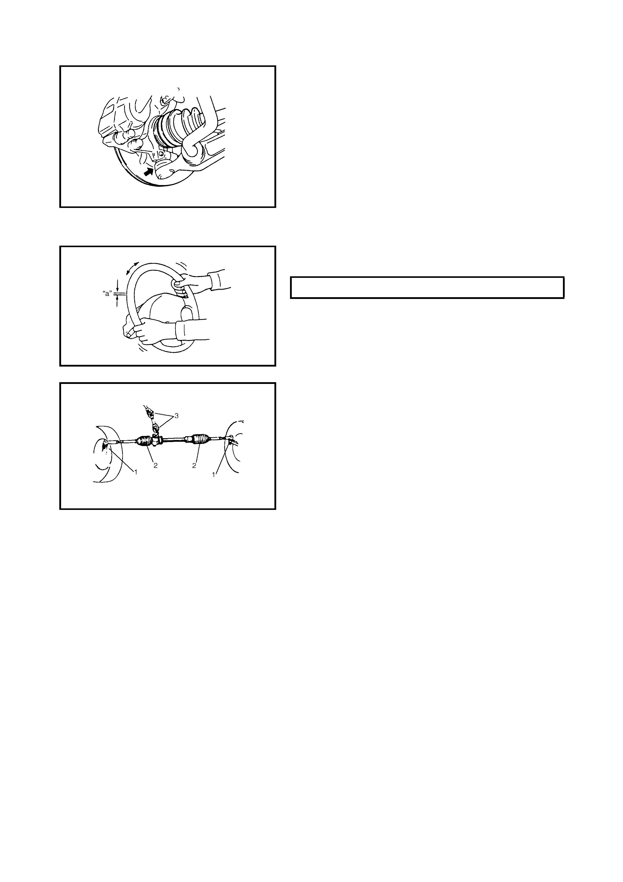
STEERING SYSTEM
Inspection
1. With the steering set straight-ahead, check the
steering wheel for play and rattles.
2. Check the bolts and nuts for tightness and retighten as
necessary. Repair or replace any defective parts.
3. Check the steering linkage for looseness and damage.
Repair or replace any defective parts.
4. Check the steering linkage boots (1) and (2) and
steering gear case for damage (leak, detachment, tear,
etc.). If damage is found, replace the defective boot
with a new one.
If a dent is found on steering gear case boots, correct it
to original the shape by turning steering wheel to the
right or left fully, holding it for a few seconds.
5. Check the steering shaft universal joints (3) for rattles
and damage. If a rattle or damage is found, replace the
defective part with a new one.
6. Check that the steering wheel can be turned fully to the
right and left. Repair or any replace defective parts.
7. Also check that the steering wheel can be turned fully
to the right and left more lightly when engine is running
at idle speed than when it is stopped. Repair if found
faulty.
8. Check wheel alignment, refer to Section 3A, FRONT
END ALIGNMENT.
STEERING WHEEL PLAY (a) 0 – 30 mm
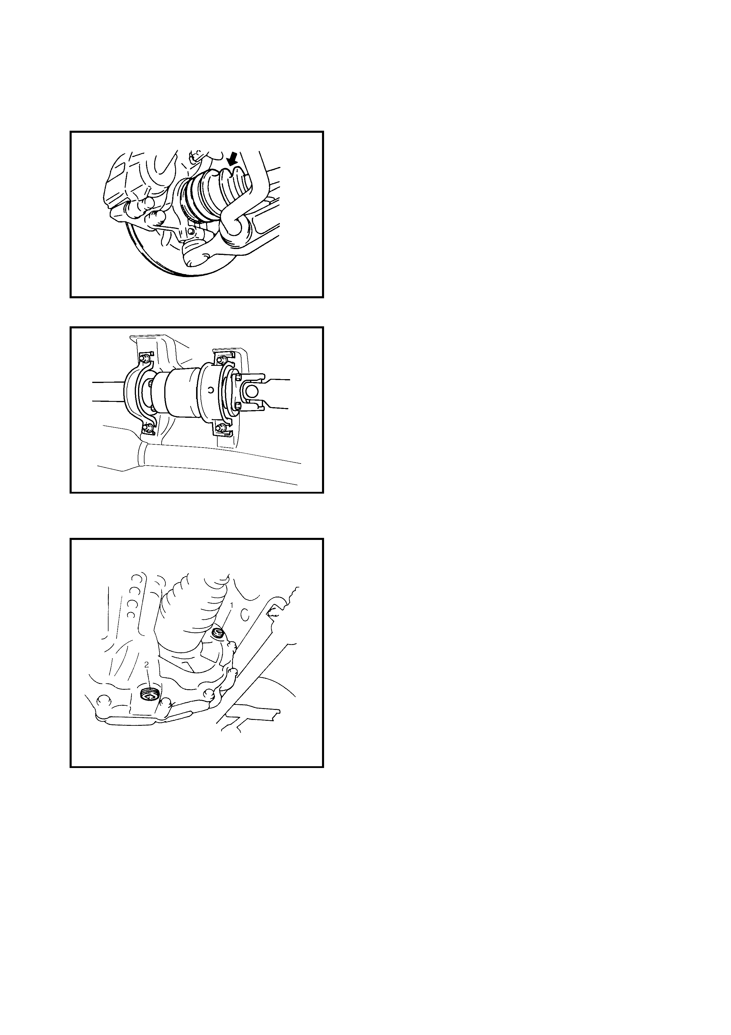
DRIVE SHAFT (AXLE) BOOTS / PROPELLER
SHAFTS
Drive Shaft (Axle) Boots Inspection
Check the drive shaft boots (wheel side and differential
side) for leaks, detachment, tear or other damage.
Replace boot as necessary.
Propeller Shaft Inspection
1. Check the propeller shaft connecting bolts for loose-
ness. If required, tighten to specified torque, refer to
Section 4B, PROPELLER SHAFTS.
2. Check the propeller shaft joints for wear, play and
damage.
If any defect is found, replace.
3. Check the propeller shaft centre support for intrusion of
foreign matter, cracks, abnormal noise and damage. If
any defect is found, replace.
MANUAL TRANSMISSION OIL
Inspection
1. Inspect the transmission case for evidence of oil
leakage. Repair any leaks as required.
2. Make sure that the vehicle is level.
3. Remove the transmission oil filler / level plug (1).
4. Check the oil level.
If oil flows out of the level plug hole or if it is level with
the hole, the oil level is correct.
If the oil level is insufficient, fill with specified oil up to
the level hole.
For the oil specifications, refer to Section 7A,
3.1 OIL CHANGE.
5. Apply sealant to filler/level plug and tighten it to
specified torque.
Replacement
1. Place the vehicle level and drain the oil by removing
the drain plug (2).
2. Apply se alant to drain pl ug after clean ing it a nd tighte n
drain plug to specified torque.
3. Pour specified oil up to level hole.
4. Tighten filler plug to specified torque.
For recommended oil, its amount and tightening torque
data, refer to Section 7A, 3.1 OIL CHANGE.
AUTOMATIC TRANSMISSION FLUID
Inspection
1. Inspect the transmission case for evidence of fluid
leakage. Repair any leaks as required.
2. Place the vehicle level for fluid level check.
3. The oil level is checked by removing the dipstick (1). A
different reading is given if the transmission is hot or
cold, refer to Section 7B, 3.1 MAINTENANCE
SERVICE and perform the check under the specified
conditions. If the fluid level is low, replenish with
specified fluid.
Replacement
1. Inspect the transmission case for evidence of fluid
leakage. Repair any leaks as required.
2. Place the vehicle level for fluid level check.
3. Remove the drain plug (1) and change the fluid, refer
to Section 7B, 3.1 MAINTENANCE SERVICE.
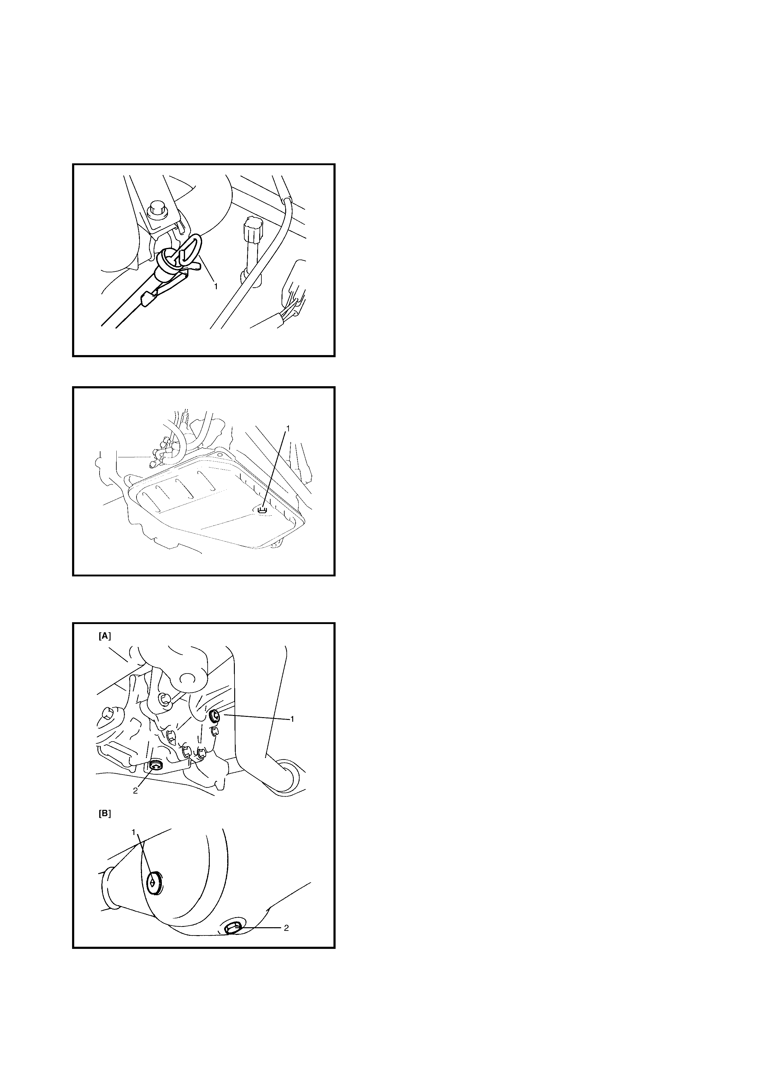
TRANSFER OIL & REAR DIFFERENTIAL OIL
Inspection
1. Check the transfer case or differential for evidence of
oil leakage. Repair any leaks as required.
2. Place the vehicle level for oil level check.
3. Remove the oil filler / level plug (1).
4. Check the oil level for the transfer [A] or rear differential
[B].
If oil flows out of the level plug hole or if it is level with
the hole, the oil level is correct.
If the oil level is insufficient, fill with specified oil up to
the level hole.
For the oil specifications, refer to
Section 7D, 3.1 OIL CHANGE for the transfer or
Section 7F, 3.1 OIL CHANGE for the rear differential.
5. Apply sealant to filler/level plug and tighten it to
specified torque.
Replacement
Remove the drain plug (2) and change the transfer oil
and differential oil with new specified oil , refer to
Section 7D, 3.1 OIL CHANGE or
Section 7F, 3.1 OIL CHANGE for the rear differential.
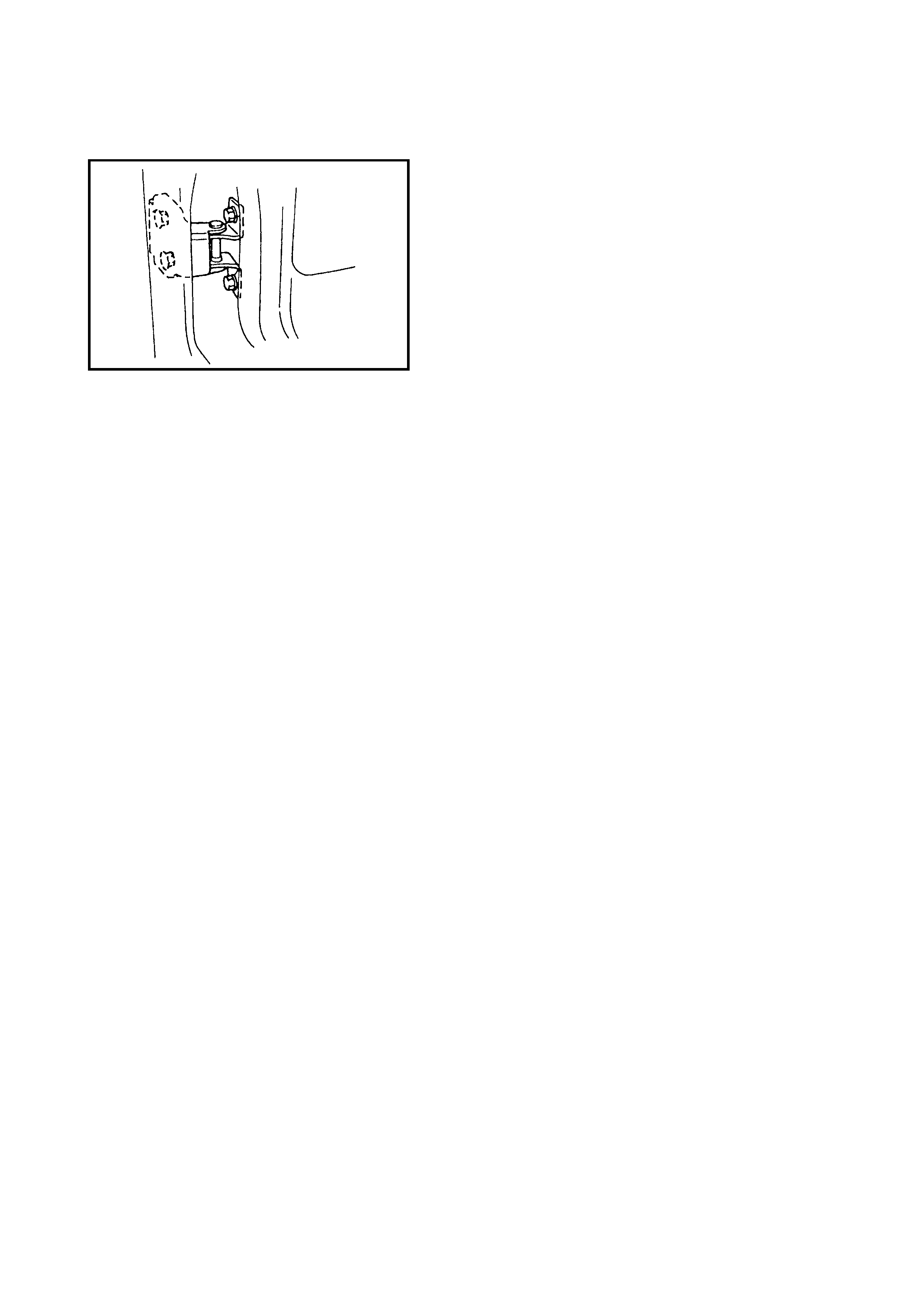
LATCHES, HINGES AND LOCKS
Inspection
DOORS
Check that each front, rear and back door opens and
closes smoothly and locks securely when closed.
If any ma lfunc tion i s found, l ubricat e the hinge and latc h or
repair door lock system.
ENGINE HOOD
Check that the secondary latch operates properly.
It must ke ep the hoo d from o pening compl etely even when
pulling the hood release handle.)
Also check that the hood opens and closes smoothly, cor-
rectly and locks securely when closed.
If any malfunction is found, lubricate the hinge and latch, or
repair hood lock system.

3. FINAL INSPECTION
SEATS
Check that the seat slid es smoo thly and locks se curely at any p osition. Al so chec k that the reclini ng mecha-
nism of the front seat back can be locked at any angle.
SEAT BELT
Inspect the seat belts including the webbing, buckles, latch plates, retractors and anchors for damage or wear .
Check that the seat belt can be securely locked. If REPLACE BELT label on front seat belt is visible, replace
the seat belt assembly.
BATTERY ELECTROLYTE LEVEL CHECK
Check that the electrolyte level of all battery cells is between the upper and lower level lines on the case. If the
battery is equipped with built-in indicator, check the battery condition by the indicator.
ACCELERAT O R PEDAL OPERATION
Check that the pedal operates smoothly without getting caught or interfered by any other part.
ENGINE START
WARNING:
Before pe rforming th e followi ng check, h ave eno ugh room a round the vehicle, firmly
apply both the parking brake and the regular brakes and do not use the acceler ator pedal. If the
engine starts, be ready to turn OFF the ignition promptly. Take these precautions as the vehicle
could move without warning and possibly cause personal injury or proper ty damage.
For automatic transmission vehicles, try to start the engine in each select lever position. The starter motor
should crank only in P (Park) or N (Neutral).
For manual transmission vehicles, place the shift lever in Neutral, depress clutch pedal fully any try to start.
EXHAUST SYSTEM CHECK
Check for leakage, cracks or loose supports.
CLUTCH (FOR MANUAL TRANSMISSION)
Check for the following:
• Clutch is completely released when depressing the clutch pedal,
• No slipping of the clutch occurs when the releasing pedal and accelerating.
• The clutch itself is free from any abnormal condition.
GEARSHIFT OR SELECT LEVER
Check th e gear shift or sele ct lev er for sm ooth shi fting to all pos ition s and for goo d perfo rmance o f the tran s-
mission in any position.
With an automatic transmission equipped vehicle, also check that the shift indicator indicates correctly
according to which position the select lever is shifted to.
With an automatic transmission equipped vehicle, make sure that the vehicle is at complete stop when shifting
the select lever to P range position and release all brakes.

BRAKE
Foot Brake
Check the fol lowi ng :
• The brake pedal has the correct travel,
• The brakes function properly,
• They are free from noise,
• The vehicle does not pull to one side when brakes are applied.
• The brakes do not drag.
Parking Brake
• Check that the lever has the correct amount of travel.
• Chec k that the parking brak e is fully effectiv e when the ve hicle is stopped on a sl ope with the brak e lever
engaged.
WARNING:
To avoid personal injury or property damage, ensure there is nothing in the way down-
hill. Be prepared to apply the regul a r brakes quickly should the vehicle start to move.
STEERING
• Check to that the steering wheel is free from instability, or abnormally heavy feeling.
• Check that the vehicle does not wander or pull to one side.
ENGINE
• Check that the engine responds readily at all speeds.
• Check that the engine is free from abnormal noises and abnormal vibration.
BODY, WHEELS AND POWER TRAIN SYSTEM
Check t hat the bo dy, wheels and p ower trai n system are free fr om abn ormal noi se and vibrati on or any o ther
abnormal condition.
METERS AND GAUGES
Check that the speedometer, odometer, fuel meter, temperature gauge, etc. are operating accurately.
LIGHTS
Check that all lights operate properly.
WINDSHIELD DEFROSTER
Periodically check that air blows from the defroster outlet when operating the heater or air conditioning.
Set the mode control lever to the defroster position and fan switch lever to HI position for this check.
4. RECOMMENDED FLUID S AND LUBR ICAN TS
ENGINE OIL ACEA service classification A2 or A3 viscosity grade 10W-30.
ENGINE COOLANT 30% Holden Cruze coolant part number 92145591 mixed with 70%
water.
BRAKE FLUID DOT 3, SAE spec. J1730
MANUAL TRANSMISSION OIL Gear Oil API GL-4 SAE 75W-90 or equivalent.
TRANSFER OIL Gear Oil API GL-5 SAE 80W-90 Hypoid or equivalent
DIFFERENTIAL OIL Gear Oil API GL-5 SAE 80W-90 Hypoid or equivalent
AUTOMATIC TR ANSMISSION
FLUID ATF DEXRON-III or equivalent
DOOR HINGES Engine oil or water resistant chassis grease
HOOD LATCH ASSEMBLY Engine oil or water resistant chassis grease
KEY LOCK CYLINDER Spray lubricant
Techline
Techline