
SECTION 0C - TECH 2
1. GENERAL INFORMATION
2. PROGRAMMING TECH 2
2.1 GENERAL INFORMATION
2.2 STANDARD UPDATE
2.3 CUSTOM UPDATE
3. USING TECH 2 ON THE VEHICLE
3.1 CONNECTING TECH 2 TO THE VEHICLE
3.2 ENGINE APPLICATION MENU
3.3 EPI ENGINE FUNCTIONS
3.4 TRANSMISSION APPLICATION MENU
3.5 TRANSMISSION FUNCTIONS
3.6 CHASSIS APPLICATION MENU
Antilock Braking System (ABS)
3.7 ABS FUNCTIONS
3.8 CHASSIS APPLICATION MENU
Electronic Power Steering
3.9 ELECTRONIC POWER STEERING
FUNCTIONS
3.10 BODY APPLICATION MENU
Immobiliser
3.11 IMMOBILISER FUNCTIONS
3.12 BODY APPLICATION MENU
Airbag (SRS)
3.13 AIRBAG FUNCTIONS
1. GENERA L INFORMATION
The Tech 2 is a hand-held diagnostic computer which has been designed specifically to help Retail outlet
Technicians diagnose and repair the electronic systems used on Holden vehicles.
NOTE: Due to the constant evolution of TECH 2 software, the screens shown in this section may differ slightly
from those displayed for the vehicle being tested.
2. PROGRAMMING TECH 2
2.1 GENERAL INFORMATION
Before Tech 2 can be used on a vehicle it will have to be
programm ed with the lates t software. Tech 2 pr ogramming
is used to update Tech 2. TIS 2000 contains the current
Tech 2 applications (program) and one preceding version.
Tech 2 can be programmed using the following procedure.
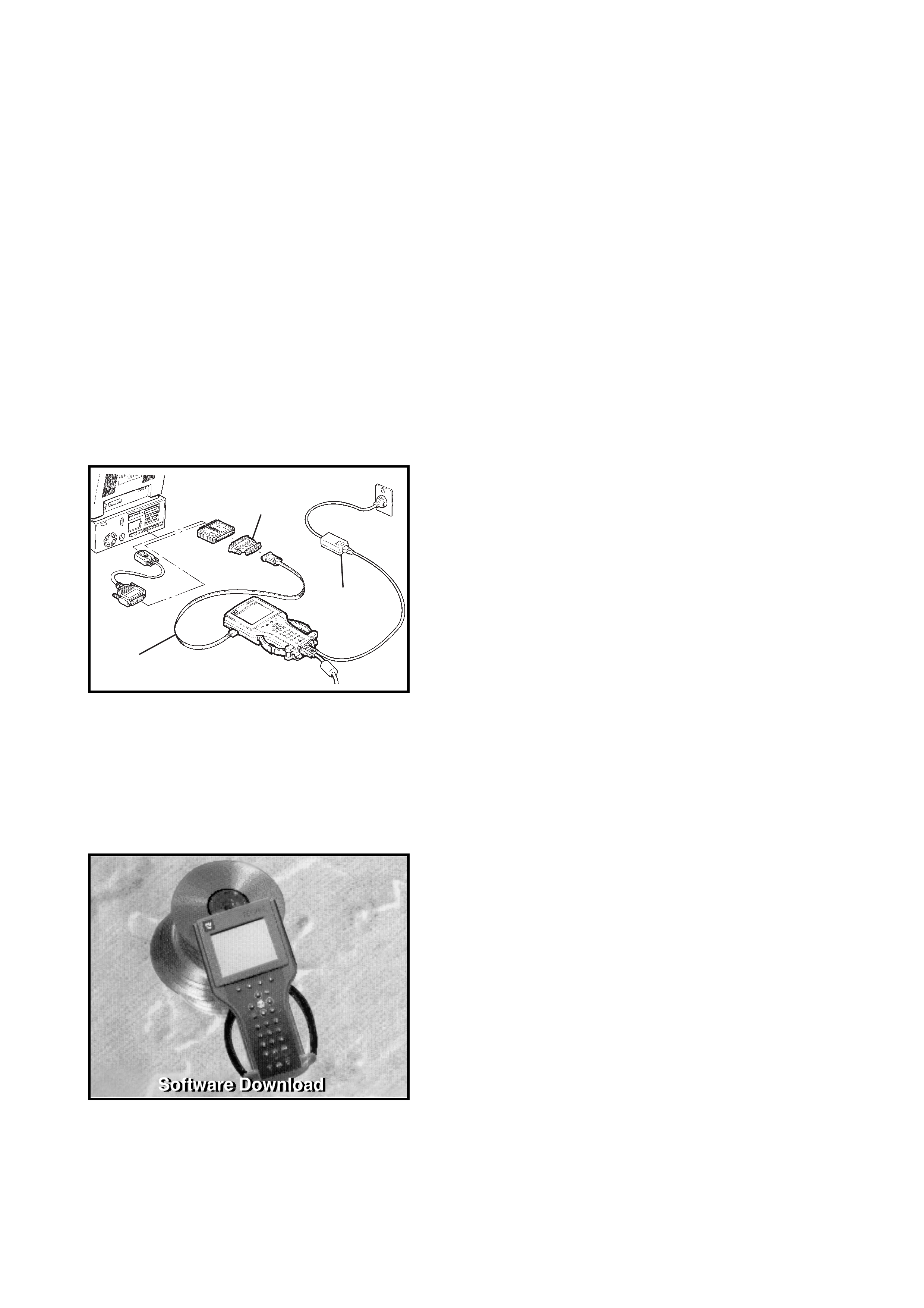
1. Connect the RS-232 (1) cable to the Tech 2 RS-232
communication port.
2. Connect the other end of the RS-232 cable to the DB-9
adapter and then connect the DB-9 adapter to the
serial communication port of your computer.
NOTE: If your com pute r has a 25 pin s er ial c omm unic atio n
port you will need to fit the 25/9 pin adapter between the
nine pin DB-9 adapter and the serial communication port.
3. Connect the AC power supply to the Tech 2 power
jack.
4. Press the PWR button to turn on Tech 2.
5. From the TIS 2000 Main Menu, click on the Software
Download icon.
There are two download modes: Standard and Custom.
Standard installs the latest software version of the cur-
rently programmed language and Make onto the Tech 2.
Custom allows you to perform backdating, install different
Make software or alternate languages onto the Tech 2.
2.2 STA NDARD UPDATE
The procedure for performing a standard Tech 2 update
using the TIS 2000 Software Download is as follows:
1. Connect the Tech 2 to the PC using the RS- 232 cabl e,
DB-9 adapter and the 25/9 pin adapter if required.
2. Power up the Tech 2 using the AC power supply that is
supplied with the Tech 2 kit.
Tech 2 must be at the Title Screen.
YGM0C05
1
2
3
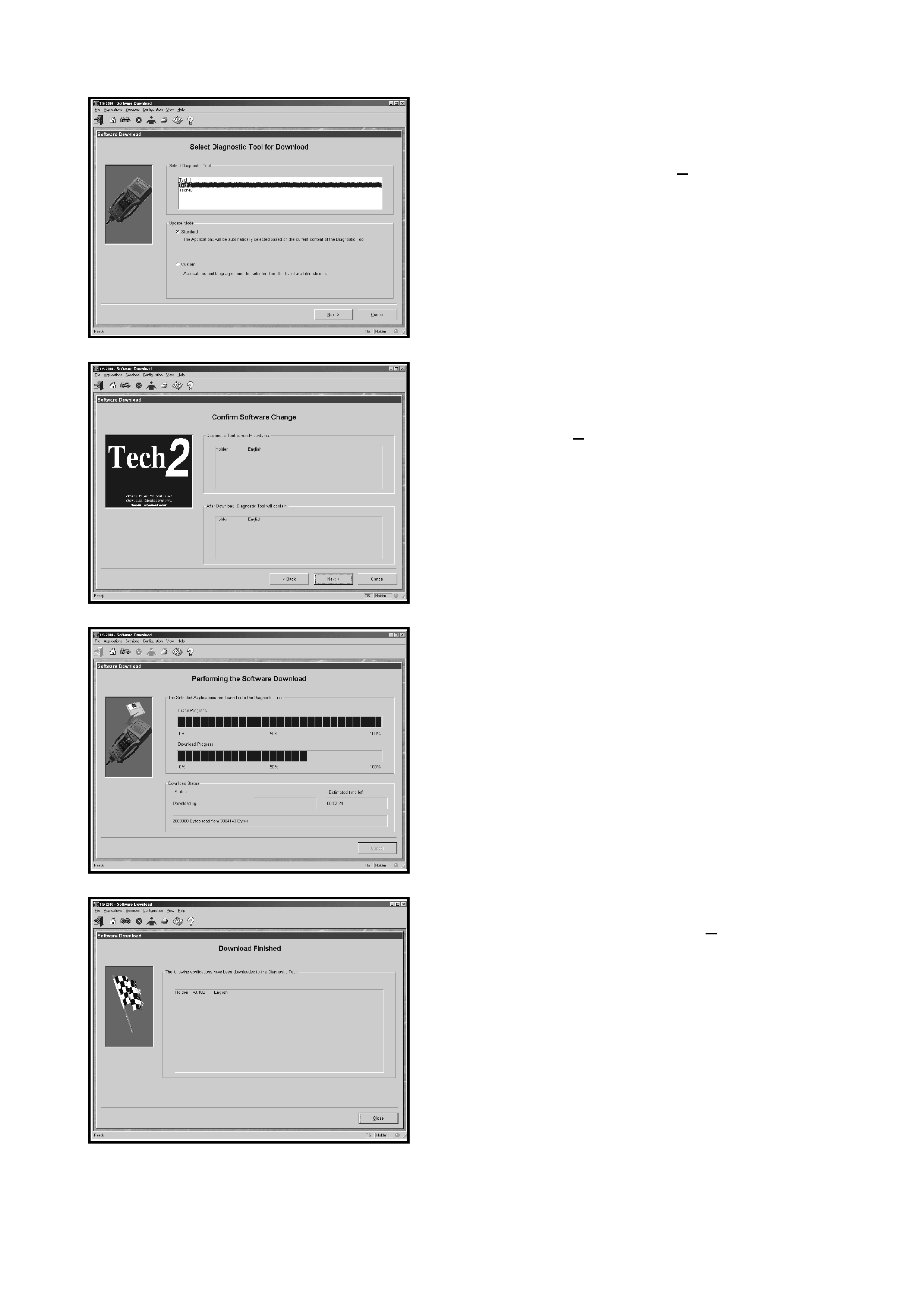
3. At the TIS 2000 Select Diagnostic Tool for
Download screen highlight your selection (TECH 2)
and select the Standard update mode.
After making your selections, click Next>. A message will
appear indicating the PC is reading the contents of the
diagnostic tool.
4. The PC will display a Confirm Software Change screen
showing what software version the Tech 2 currently
contains and what it will contain after the software
download. Click Next> to continue.
5. A Performing the Software Download screen will
appear. It tracks the status of the software download.
6. When the software do wnload is compl ete, a Download
Finished screen appears. Click on Close to close the
application. The scan tool now contains the latest
software.
2.3 CUSTOM UPDATE
A custom update is used to backdate the TECH 2, install
Non-Hold en software or install di fferent lan guage s oftware.
After selecting Custom as the update mode from the selec-
tion screen, do the following:
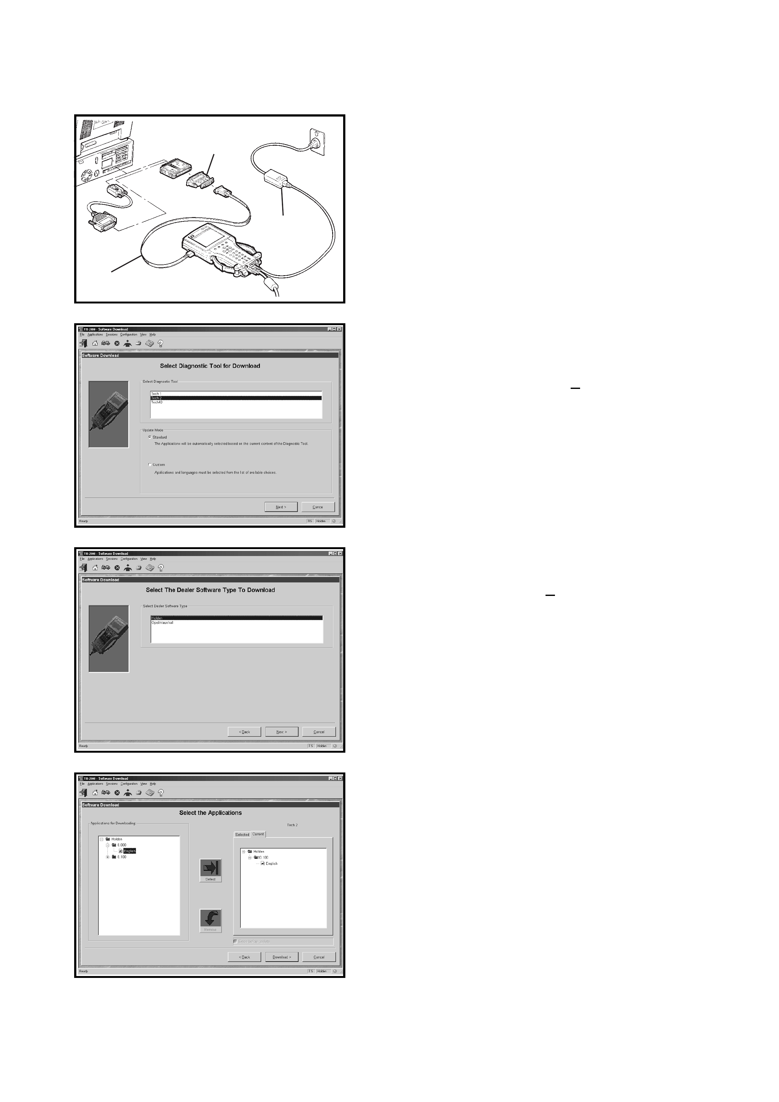
1. Connect the TECH 2 to the PC using the RS-232 cable
(1), DB-9 adapter and the 25/9 pin (2)adapter if
required.
2. Power up the Tech 2 using the AC power supply (3)
that comes standard with the TECH 2 kit.
Tech 2 must be at the Title Screen.
3. At the TIS 2000 Select Diagnostic Tool for
Download screen highlight your selection (TECH 2)
and select the Custom update mode.
After making your selections, click Next>. A message will
appear indicating the PC is reading the contents of the
diagnostic tool.
4. The Select The Dealer Software Type to Download
screen will then be displayed. Select the desired
software type and the click Next> to continue.
5. A Se lect the Appli cation s screen will appe ar. The left
side of the screen lists software release numbers. Click
on the “+” sign to see a list of different languages for
each release.
6. Select the desired software version and language by
either double-clicking or clicking the Select icon. The
selected software will appear in the right side of the
screen.
To compare th e c urre nt a nd s elec ted Te ch 2 softw are, c li ck
on the Current or Selected tabs on the right side of the
screen.
YGM0C05
1
2
3
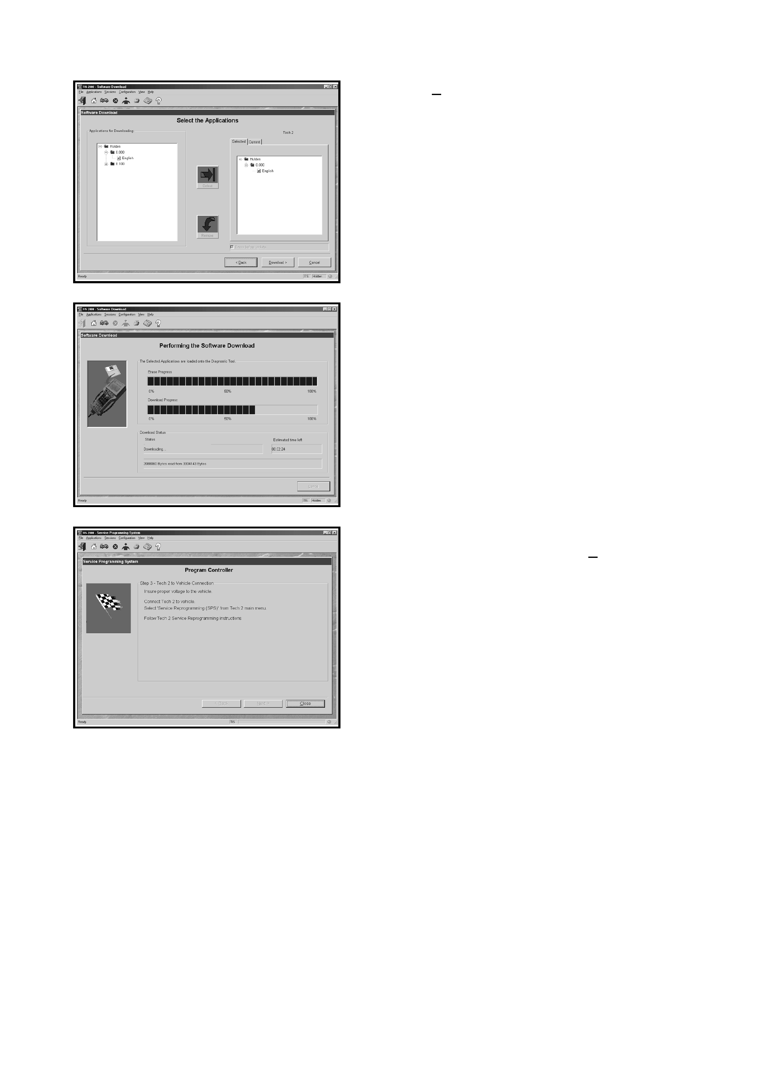
7. Click on Download> to begin the update.
8. A Performing the Software Download screen will
appear. It tracks the status of the software download.
9. When the software download is complete, a Download
Finished scree n appears. Click on Close to close the
application. The TECH 2 now contains the selected
software.
3. USING TECH 2 ON THE VEHICLE
NOTE: Due to the constant evolution of TECH 2 software,
the screens shown in this section may differ slightly from
those displayed for the vehicle being tested.
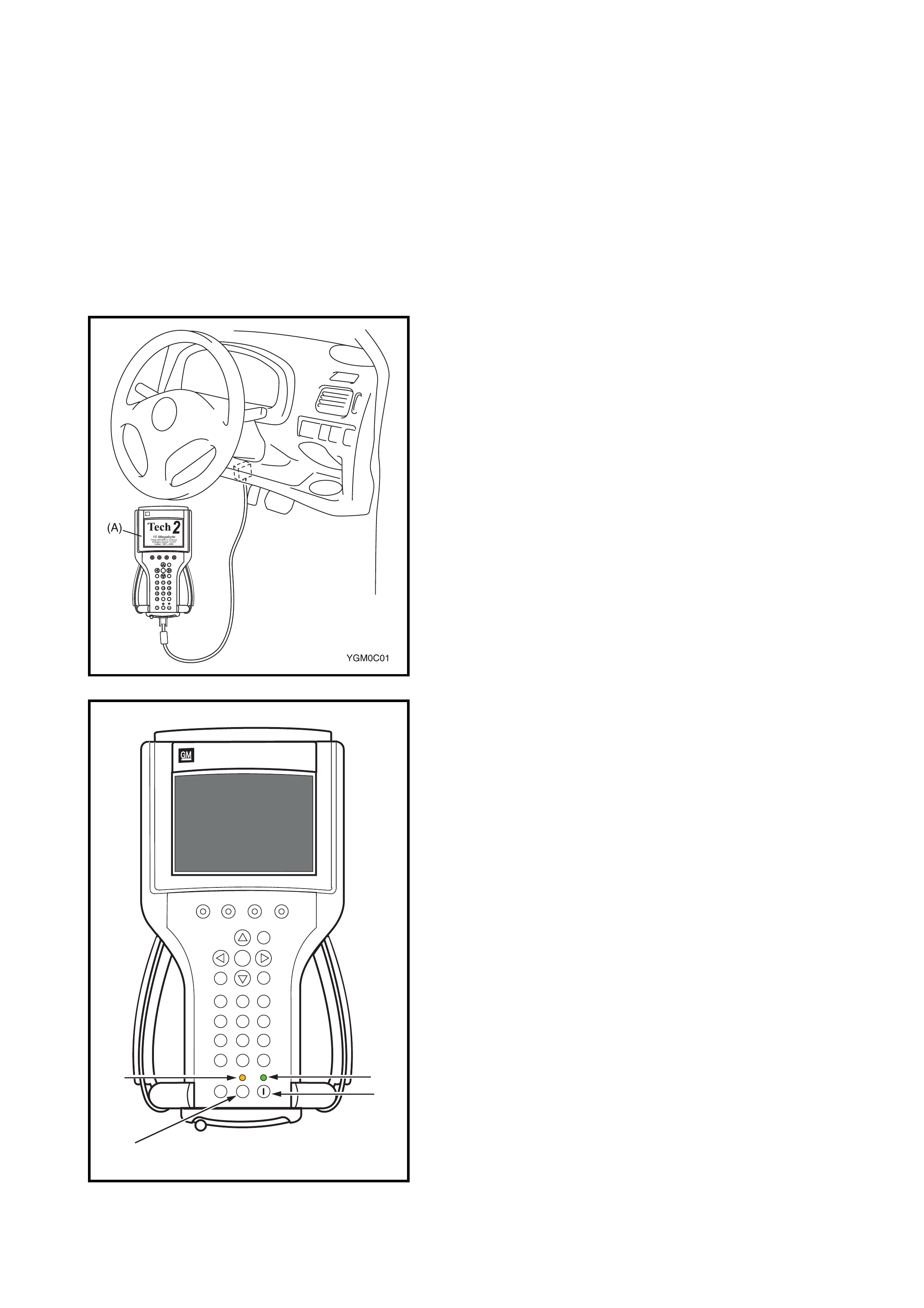
3.1 CONNECTING TECH 2 TO THE VEHICLE
1. Connect Tech 2 (A) to the vehicle DLC , with the DLC
cable and the 16/19 pin adapter.
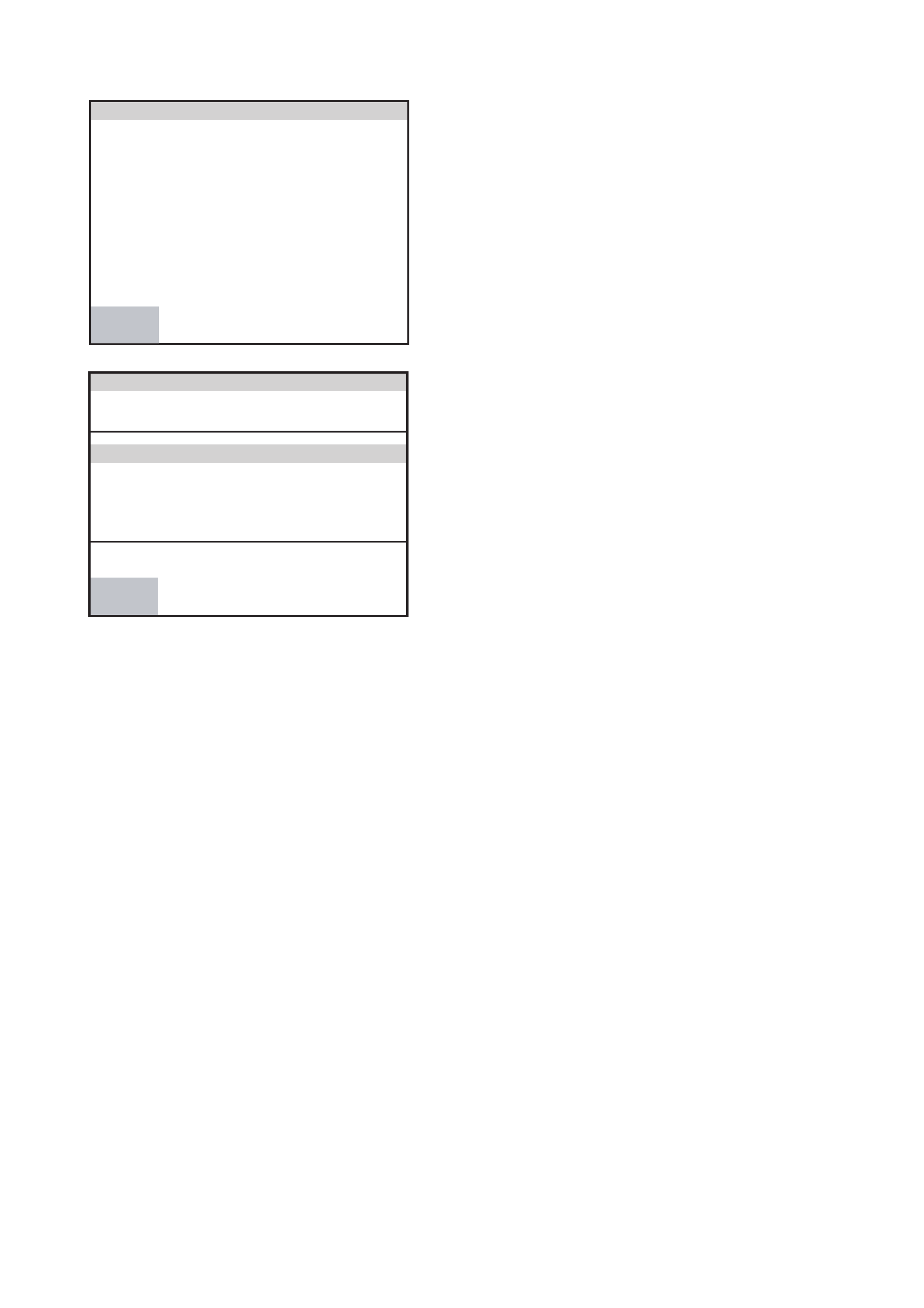
2. Switch th e unit on b y pres sing the power button (2). A
green light (1) should come on indicating that the tool is
receiving power.
NOTE: At this time the technician should see the Power On
Self Test (POST) run. The POST is a built in diagnostic self
test for the TECH 2 that sh ould find most c ommon system
faults. The POST is run on every power up to ensure the
best operation of the tool. After the completion of the
POST, the TECH 2 unit w ill brie fly sh ow the P OST results.
If POST passes, the tool will continue onto the title screen.
If POST fails, results of all tests will be displayed, and this
should show which test failed. POST failures may be
classified as fatal or non-fatal. A fatal error will not allow the
user to continue using the tool. Failure of the keypad would
be an example of a fatal error . Non-fatal errors found during
the POS T will allow continued use of the TECH 2, but wi th
some limitations. If either a fatal or non-fatal error occurs,
refer to the Troubleshooting section of the TECH 2 User's
Guide.
Legend
1. Power Status Indicator Light
2. PWR (Power) Key
3. SHIFT Key
4. SHIFT Key Status Indicator Light
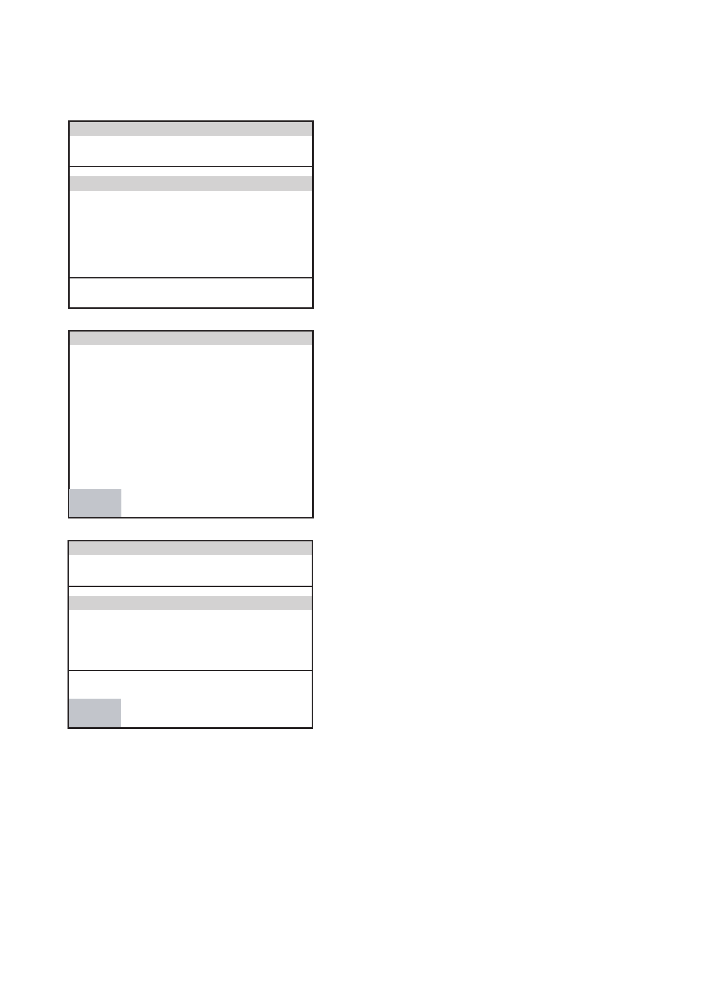
3. At the Tech 2 title screen press the ENTER key to
continue.
F
0
F
3
F
6
F
9
F
1
F
4
F
7
F
2
F
5
F
8
?
2
Tech
10Megabyte
Press[ENTER]tocontinue
SoftwareV ersion1 1.010
Holden1997-2002
2
1
4
3YGM0C19

4. A selection can be made from the Main Menu, either by
using a function key or by using the arrow keys to
highlight a menu choice and pressing ENTER.
•NOTE: You will then need to supply some additional
information to the TECH 2. This requires navigation
through a series of lists (called picklists). On some
menus or picklists, the user can use a function key to
make a menu selection, but most of the picklists
require using the selection and action keys. If a mis-
take is made in the selection process, or if a different
application or function is desired, press EXIT to back
up one level. Within an application, there may be soft
keys which are available for use. These soft keys allow
access to additional tool functions without exiting a cur-
rent tool funct ion. S oft keys are ma de up of sets wh ich
will appear together. To see the next set of soft keys,
select the More soft key.
The TECH 2 Main Menu contains the following:
F0: Diagnostics
Contains all functions to test, diagnose, monitor and pro-
gram the different vehicle systems.
F1: View Capture Data
Contains all functions to work with one or two previously
recorded snapshots on one or two vehicles. This function is
to enable the viewing of captured data without a vehicle.
F2: Tool Options
Contains the TECH 2 self test, set clock, set units, set
screen cont ra st and Ge tti ng Started .
F3: Download/Upload Help
Contains hel p informati on on the d ownloadin g and uplo ad-
ing from the TECH 2 to the TIS 2000 CD-ROM.
Press the ENTER key with F0: Diagnostics selected to
continue.
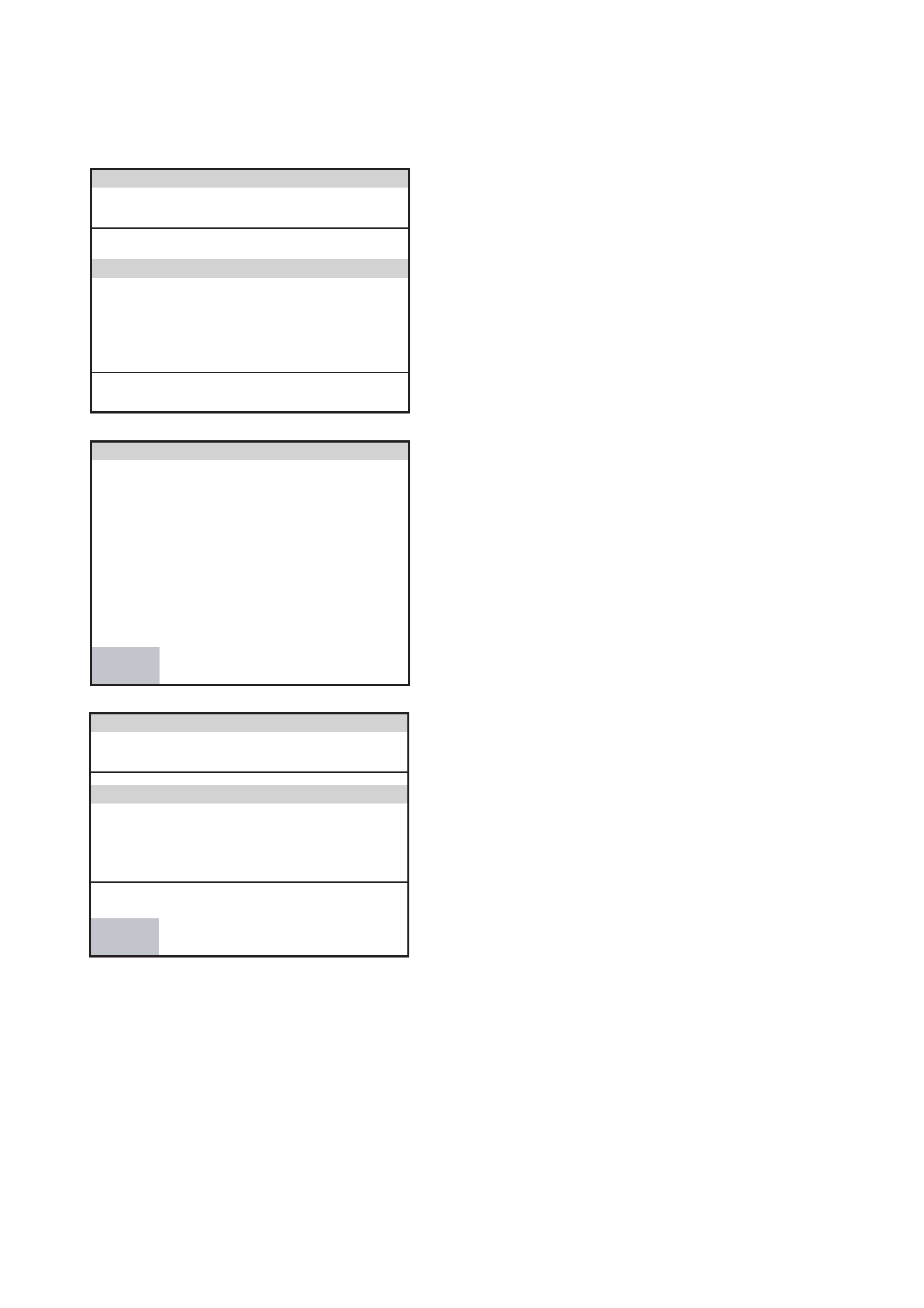
5. Select the correct Model Year with the arr ow keys an d
the pr es s ENTER. The V ehicle identification screen will
then be displayed.
Main Menu
F0: Diagnostics
F1: View Capture Data
F2: Tool Options
F4: Download/Upload Help
YGM0C20
Vehicle Identification
Select one of the following
Model Year(s)
(2) 2002
(1) 2001
(Y) 2000
(X) 1999
(W)1998
(V) 1997
YGM0C20
(2) 2002

6. Select the correct Vehicle Type with the arrow keys
and the press ENTER. The System Selection Menu will
then be displayed.
7. The desired system can be selected from the System
Selection Menu with the function keys or with arrow
keys and then press ENTER.
F0: Engine contains all functions to test, diagnose and
monitor the engine systems that communicate with the
Tech 2 via the Engine Control Module (ECM).
F1: Transmission contains all functions to test, diagnose
and monitor the Automatic Transmission systems th at
communicate with Tech 2 via the Transmission Control
Module (TCM).
F2: Chassis co ntains all functio ns to tes t, di agn ose, mo ni-
tor th e vehicle’s ch assis systems; ABS and Electronic
Power Ste ering Modules .
F3: Body contains all functions to test, diagnose, monitor
the Immobiliser and Airbag Systems.
3.2 ENGINE APPLICATION MENU
1. Select th e engine type f rom th e Ve hicle Identificat ion
menu with the arrow keys, then press ENTER.
Vehicle Identification
Select one of the following
VX Commodore
VU Utility
WH Statesman & Caprice
V2 Monaro
Cruze
Corsa-C
Corsa-C Combo
YGM0C22
Cruze
System Selection Menu
F0: Engine
F1: Transmission
F2: Chassis
F3: Body
YGM0C23
(2) 2002
Vehicle Identification
Select one of the following
Engine
Engine
YGM0C24
Engine
2. Turn on the ignition and press the Confirm soft key.
3. The Engine identification screen will then display the
ECM iden tification info rmation. Pr ess the Confirm soft
key, the engine application menu will then be
displayed.
NOTE: If Tech 2 is a ble to communic ate with the ECM th e
Engine identification information will be displayed. If Tech 2
is unable to communicate with the ECM, Tech 2 will display
“Wa iting for Data”.
The following functions can be selected from the engine
application menu:
F0: Diagnostic Trouble Codes
F1: Data Display
F2: Snapshot
3.3 ENGINE FUNCTIONS
F0: Diagnostic Trouble Codes
In this test mode, DTCs stored by the ECM can be displayed or cleared. When F0: Diagnostic Trouble Codes
is selected, there are an additional two modes:
F0: Read DTC Info As Stored By ECM: All current DTC(s) will be displayed.
F1: Clear DTC Information: Clears all current DTC(s) in the ECM memory.
F1: Data Display
In this test mode, the TECH 2 continuously monitors and displays 35 engine data parameters.
F2: Snapshot
In this mode, the TECH 2 scan tool captures data before and after a selected snapshot triggering condition
which may or may not set a DTC.
F3: Miscellaneous Tests
In this mode, TECH 2 assumes control of various output devices for system testing:
F0: Spark Timing Check
F1: Idle Speed Control
F2: Cooling Fan
F3: EGR Valve Control
Engine
(2) 2002 Cruze
Engine
Turn On Ignition!
YGM0C25
Confirm
Engine
(2) 2002 Cruze
Engine
Part Number 33920-70H2
Component ID 33920-70H2
YGM0C26
Confirm
Part Number
3.4 TRANSMISSION APPLICATION MENU
1. Select the transmission type from the Vehicle
Identification menu with the arrow keys, then press
ENTER and follow the screen instructions.
2. Turn on the ignition and press the Confirm soft key.
3. The T ransmission Identification screen will then display
the Part Number and the Component ID. Press the
Confirm soft key, the transmission application menu
will then be displayed.
NOTE: If Tech 2 is able to communicat e w ith the TCM the
Transmission Identification information will be displayed. If
Tech 2 is unabl e to communi cate wit h the TCM, Tech 2 will
display “Waiting for Data”.
The following functions are available in the transmission
application menu:
F0: Diagnostic Trouble Codes
F1: Data Display
F2: Snapshot
3.5 TRANSMISSION FUNCTIONS
F0: DIAGNOSTIC TROUBLE CODES
In this tes t mo de, DTCs sto red by the T CM c an be displ ayed or cl eared . Wh en F 0: Di agno st ic Trouble Codes
is selected, there are additional two modes:
F0: Read DTC Info As Stored by TCM: All current DTC(s) will be displayed.
F1: Clear DTC Information: Clears all current DTC(s) in the TCM memory.
F1: DATA DISPLAY
In this mode, TECH 2 continuously monitors transmission data.
F2: SNAPSHOT
In th is test mode, the TECH 2 scan tool cap tures da ta before and a fter a sn apshot trig geri ng con ditio n which
may or may not set a DTC.
Vehicle Identification
Select one of the following
Transmission
Automatic Transmission
YGM0C27
Automatic Transmission
Engine
(2) 2002 Cruze
Automatic Transmission
Turn On Ignition!
YGM0C28
Confirm
Transmission
(2) 2002 Cruze
TCM (Transmission Control Module)
Part Number 38880-70H5
Component ID 38880-78-FJ
YGM0C29
Confirm
Part Number

3.6 CHASSIS APPLICATION MEN U
ANTILOCK BRAKING SYSTEM (ABS)
1. Select the correct chassis system from the Vehicle
Identification menu with the arrow keys, then press
ENTER and follow the instructions on the screen.
2. Turn on the ignition and press the Confirm soft key.
3. The System identification screen will then display the
control module Part number and Component ID.
Press the Confirm soft key, and the Chassis application
menu will then be displ aye d.
The following functions are available in the ABS Chassis
application menu:
F0: Diagnostic Trouble Codes
F1: Data Display
F2: Snapshot
3.7 ABS FUNCTIONS
F0: DIAGNOSTIC TROUBLE CODES
In this test mode, DTC(s) stored by the ABS Control Module can be displayed or cleared. When F0: Diagnos-
tic Trouble Codes is selected, there are an additional two modes:
F0: Read DTC Info as Stored by ECU: Current DTC(s) will be displayed.
F1: Clear DTC Information: Clears all current DTC(s) in the ABS Control Modules memory.
F1: DATA DISPLAY
This mode TECH 2 continuously monitors and displays seven ABS data parameters.
F2: SNAPSHOT
In t his test mode , TECH 2 capt ures data befor e and after a sn apshot triggeri ng condition which may or may
not set a DTC.
Vehicle Identification
Select one of the following
Chassis
ABS
Electronic Power Steering
YGM0C30
ABS
Chassis
(2) 2002 Cruze
ABS
Turn On Ignition!
YGM0C31
Confirm
3.8 CHASSIS APPLICATION MEN U
ELECTRONIC POWER STEERING
1. Select the correct chassis system from the Vehicle
Identification menu with the arrow keys, then press
ENTER and follow the instructions on the screen.
2. Turn on the ignition and press the Confirm soft key.
3. The System identification screen will then display the
control module Part Number and System type.
Press the Confirm soft key, and the Electronic Power
Steering application menu will then be displayed.
The following functions are available in the Chassis appli-
cation menu:
F0: Diagnostic Trouble Codes
F1: Data Display
F2: Snapshot
Vehicle Identification
Select one of the following
Chassis
ABS
Electronic Power Steering
YGM0C33
Electronic Power Steering
Chassis
(2) 2002 Cruze
Electronic Power Steering
Turn On Ignition!
YGM0C34
Confirm
Chassis
(2) 2002 Cruze
Electronic Power Steering
Part Number 38720-80H1
Component ID 38720-76A0
YGM0C35
Confirm
Part Number

3.9 ELECTRONIC POWER STEERING FUNCTIONS
F0: DIAGNOSTIC TROUBLE CODES
In this tes t mode , DTC(s ) stor ed by the Elec troni c Power St e ering Modu le c an be displayed or clea re d. Ther e
are two modes:
F0: Read DTC Info As Stored by ECU: All current DTC(s) will be displayed.
NOTE: With F0: or F1: selected and the ignition turned ON (engine not running) code C112 No engine
RPM signal will always be displayed.
With the engine running C1122 will flash.
F1: Clear DTC Information: Clears all current DTC(s) in the PCM memory.
F1: DATA DISPLAY
This mode TECH 2 continuously monitors and displays all eight Electronic Power Steering data parameters.
F2: SNAPSHOT
In this test mode, TECH 2 tool captures data before and after a snapshot triggering condition which may or
may not set a DTC.
3.10 BODY APPLICATION MENU
IMMOBILISER
1. Select the correct body system from the Vehicle
Identification menu with the arrow keys, then press
ENTER and follow the instructions on the screen.
2. Turn on the ignition and press the Confirm soft key.
3. At this point, you will be requested to enter the 4-digit
security code. This code number is 0895 for ALL YG
Cruze. Once the code has been entered, confirm the
number with the OKAY softkey, and procedd to the
next screen.
Vehicle Identification
Select one of the following
Body
Immobiliser
Airbag
YGM0C36
Immobiliser
Body
(2) 2002 Cruze
Electronic System: Immobiliser
Turn On Ignition!
YGM0C37
Confirm

4. The System identification screen will then display the
control module Part number and System type.
Pres s th e Confirm soft key, and the Immobiliser application
menu will then be displ aye d.
The following functions are available in the Immobiliser
application menu:
F0: Diagnostic Trouble Codes
F1: Data Display
F2: Snapshot
3.11 IMMOBILISER FUNCTIONS
F0: DIAGNOSTIC TROUBLE CODES
In this test mode, DTC(s) stored by the Immobiliser Control Module can be displayed or cleared.
F0:Read Current DTC: All current DTC(s) will be displayed.
F1: DATA DISPLAY
This mode TECH 2 continuously monitors and displays all Immobiliser data parameters.
F2: SNAPSHOT
In th is test mode, the TECH 2 s can tool cap tures da ta befo re and a fter a sn apshot trig geri ng con ditio n which
may or may not set a DTC. The Snapshot mode will help identify problems that may cause intermittent opera-
tion of the Immobiliser system.
F3: ADDITIONAL FUNCTIONS
In this test mode, additional operations may be carried out on the Immobiliser system.
The following operations can be performed:
F0: Erase Transponder Keys
F4: PROGRAMMING
This mode allows the programming of replacement or additional components to the Immobiliser system.
F0: Program Immobiliser Function - this function is used when installing either a new ICM or ECU.
F1: Program Transponder Keys
Body
(2) 2002 Cruze
Immobiliser
Part Number 89716841212
YGM0C38
Confirm
Part Number

3.12 BODY APPLICATION MENU
AIRBAG (SRS)
1. Select the correct body system from the Vehicle
Identification menu with the arrow keys, then press
ENTER and follow the instructions on the screen.
2. Turn on the ignition and press the Confirm soft key.
3. The System identification screen will then display the
control module Part Number and Component ID.
Press the Confirm soft key, and the Body application menu
will then be displayed.
The following functions are available in the Body applica-
tion menu:
F0: Diagnostic Trouble Codes
F1: Data Display
F2: Snapshot
Vehicle Identification
Select one of the following
Body
Immobiliser
Airbag
YGM0C39
Airbag
Body
(2) 2002 Cruze
Electronic System: Airbag
Turn On Ignition!
YGM0C40
Confirm
Body
(2) 2002 Cruze
Electronic System: Airbag
Part Number 38910-70H1
Component ID 38910-76C0
YGM0C41
Confirm
Part Number

3.13 AIRBAG FUNCTIONS
F0: DIAGNOSTIC TROUBLE CODES
In this test mode, DTC(s) stored by the Airbag Control Module can be displayed or cleared. There are two
additional modes:
F0: Read DTC Info As Stored by ECU: All current DTC(s) will be displayed.
F1: Clear DTC Information: Clears all current DTC(s) in the memory.
F1: DATA DISPLAY
In this mode TECH 2 continuously monitors and displays six Airbag System data parameters.
F2: SNAPSHOT
In t his test mode , TECH 2 capt ures data befor e and after a sn apshot triggeri ng condition which may or may
not set a DTC. The Snapshot mode will help identify problems that may cause intermittent operation of the
SRS system.