SECTION 1A - HEATING AND VENTILATION
1. GENERAL DESCRIPTION
2. DIAGNOSIS
2.1 DIA GNOS IS TAB L E
2.2 WIRING CIRCUIT
3. O N- VEH IC L E SER VICE
3.1 HEATER UNIT
Removal
Installation
3.2 BLOWER FAN MOTOR
Removal
Inspection
Installation
3.3 BLOW ER FAN MOTOR RESISTOR
Removal
Inspection
Installation
3.4 HEATER CONTROL ASSEMBLY
Removal
Installation
Inspection
3.5 A IR INLET BOX
Removal
Installation
3.6 VENTILATION LOUVRE
Removal
Installation
4. REQUIRED SERVICE MATERIAL
WARNING:
For vehicles equipped with Supplement Restraint (Airbag) System
• Service on and around the airbag sys tem components or wiring must be performed only by
an authorised HOLDEN retailer. Refer to Section 10B AIRBAG SYSTEM-COMPONENTS AND
WIRING LOCATION VIEW in GENERAL DESCRIPTION in order to confirm whether you are
performing service on or near the airbag system components or wiring. Please observe all
WARNINGS and SERVICE PRECAUTIONS, refer to Section 10B ON-VEHICLE SERVICE before
performing service on or around the airbag system components or wiring. Failure to follow
WARNINGS could result in u nintentional activation of the system or could render the system
inoper ative. Either or these two co nditions may result in severe injury.
• Technical service work must not be started for at least 90 seconds after the ignition switch is
turned to the “LOCK” position and the negative cable is di sconnected from the battery. Oth-
erwise, the system may be activated b y reserve energy in the Sensing and Diagnostic Module
(SDM).
NOTE:
The link mech anism of the heater varies depending on the specifications.
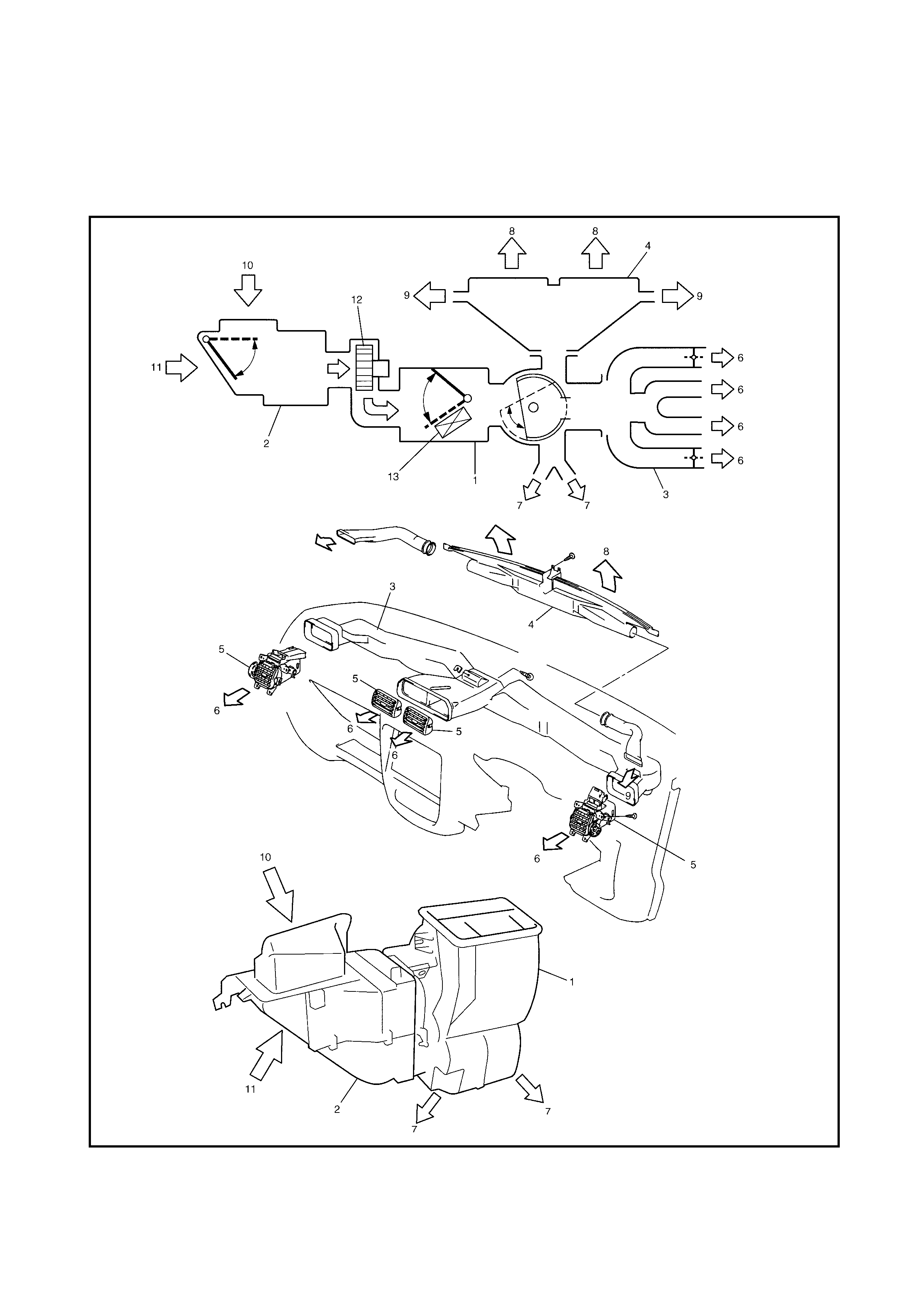
1. GENERAL DESCRIPTION
Legend
1. Heater unit 5. Ventilation louvre 9. Demister air 12. Blower fan
mot or asse mb ly
2. Air inlet box 6. Ventilation air 10. F resh air
3. Vent il ator duct 7. Foot air 11. Recirculation air 13. Heater core
4. Defroster nozzle 8. Defroster air

2. DIAGNOSIS
2.1 DIAGNOSIS TABLE
Condition P ossible Cause Correction
H eater blower fan
m ot or do e s not
operate with fan
switch ON
Fuse blown Check “HEATER” fuse, main
heater fuse and check for short cir-
cuit to ground.
Blower main relay fa ulty Check blower main relay.
Blower fan motor resisto r faulty Check resistor.
Blow er fan m otor sw itch fau lty Check blower fan swi tch.
Blower fan m otor fau lty Replace motor.
Wiring or grounding fau lty Repair as necessary.
H eater blower fan
does not opera t e
when fa n switch is in
m aximum position.
Blow er maximum relay faulty Check blower maximum relay.
Blow er fan m otor sw itch fau lty Check blower fan swi tch.
Wiring or grounding fau lty Check wiring, grounding and
repair as necessary.
Incorrect tempera-
tu re outp ut. Control cables broken or binding Check cabl es.
Temperature control lever faulty Check control lever.
Position of control cable clam p is fau lty Ch eck and adjustment.
Temperature door assembl y broken Repair temperature door
assembly.
Air ducts clogged Repair air ducts .
Heater core leaking or clogged Replace core.
Heater hoses leaking or clogged Re place hoses.
Therm ost at fa ulty Check therm os tat, referr ing to
Sect ion 6B.
When mode control
lever is chang ed, air
outlet port do es not
change or lever posi-
tion does not match
a ir ou tlet po rt .
Control cable broken or binding Check cabl e.
Mode control lever faulty Check control lever.
Position of control cable clam p is fau lty Ch eck and adjust clamp
position.Check and adjustment.
Air damper broken Repair dam per.
Air ducts l eak ing or clogged Repair air ducts.
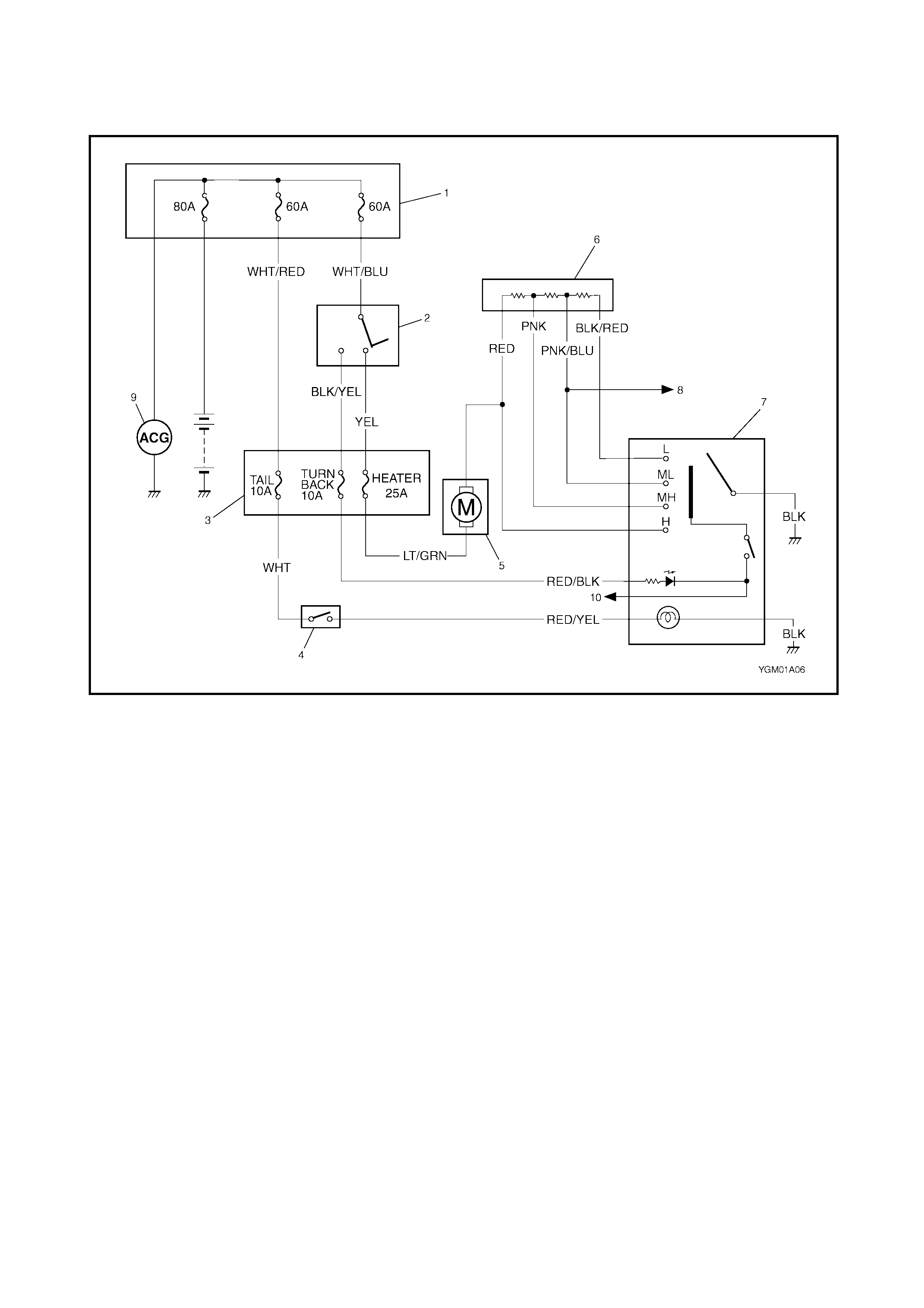
2.2 WIRING CIRCUIT
Legend
1. Main fuse box 4. Lighting switch 7. Blower fan switch 10. To ECM
2. Ignition swi tch 5. Bl ower fan motor 8. To ECM (idle up signal)
3. Circuit fuse box 6. Blower fan motor
resistor 9. Generator
3 . ON-VEHICLE SERVICE
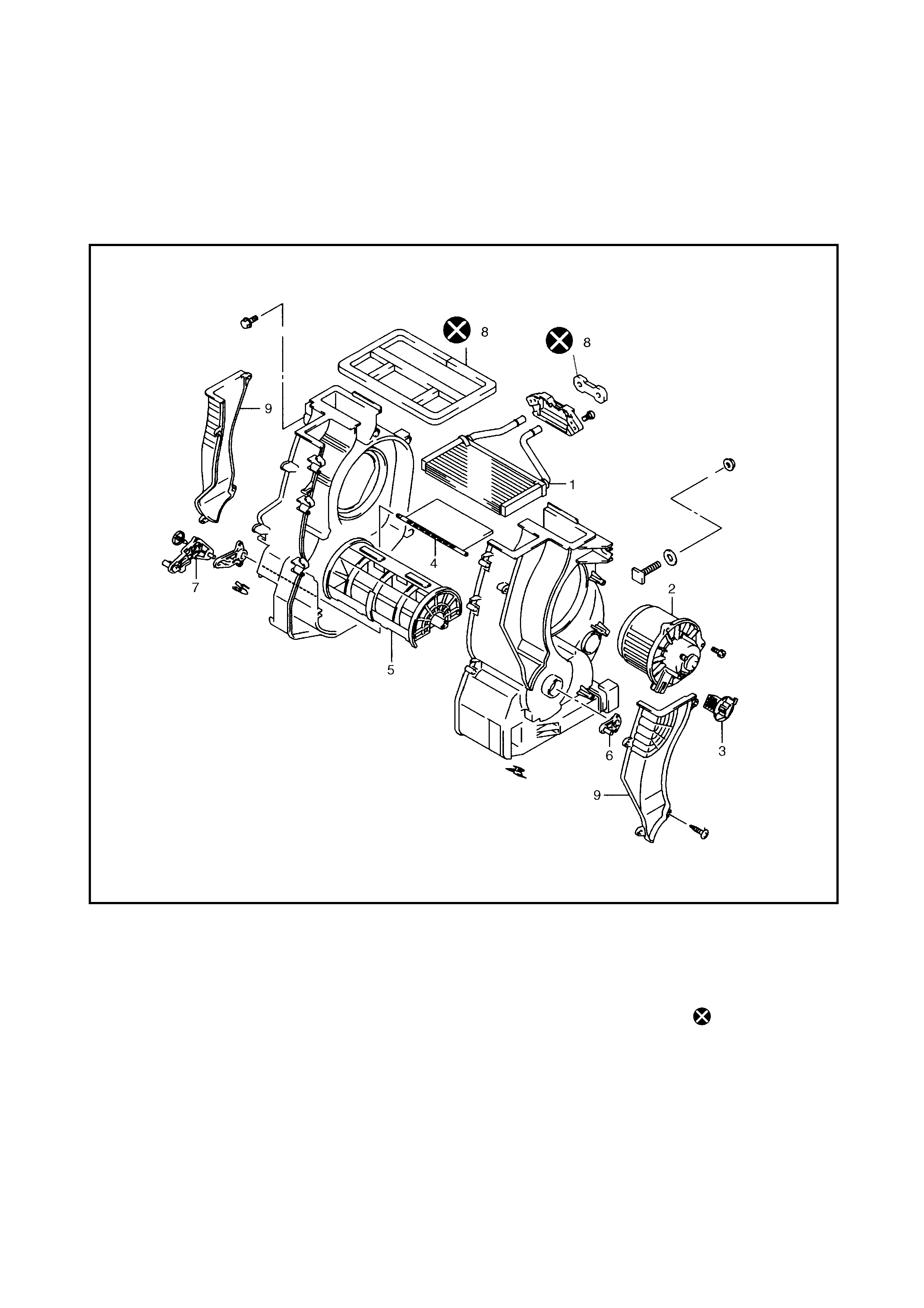
3.1 HEATER UNIT
Legend
1. Heater core 4. Temperature door
assembly 6. Air outlet control
lever assembly 8. Seal
2. Blower fan motor
assembly 9. Dem ister air
outl e t ca se
5. Air outlet control door
assembly 7. Temperature lever
assembly
3. Blower fan motor
resistor Do not reuse
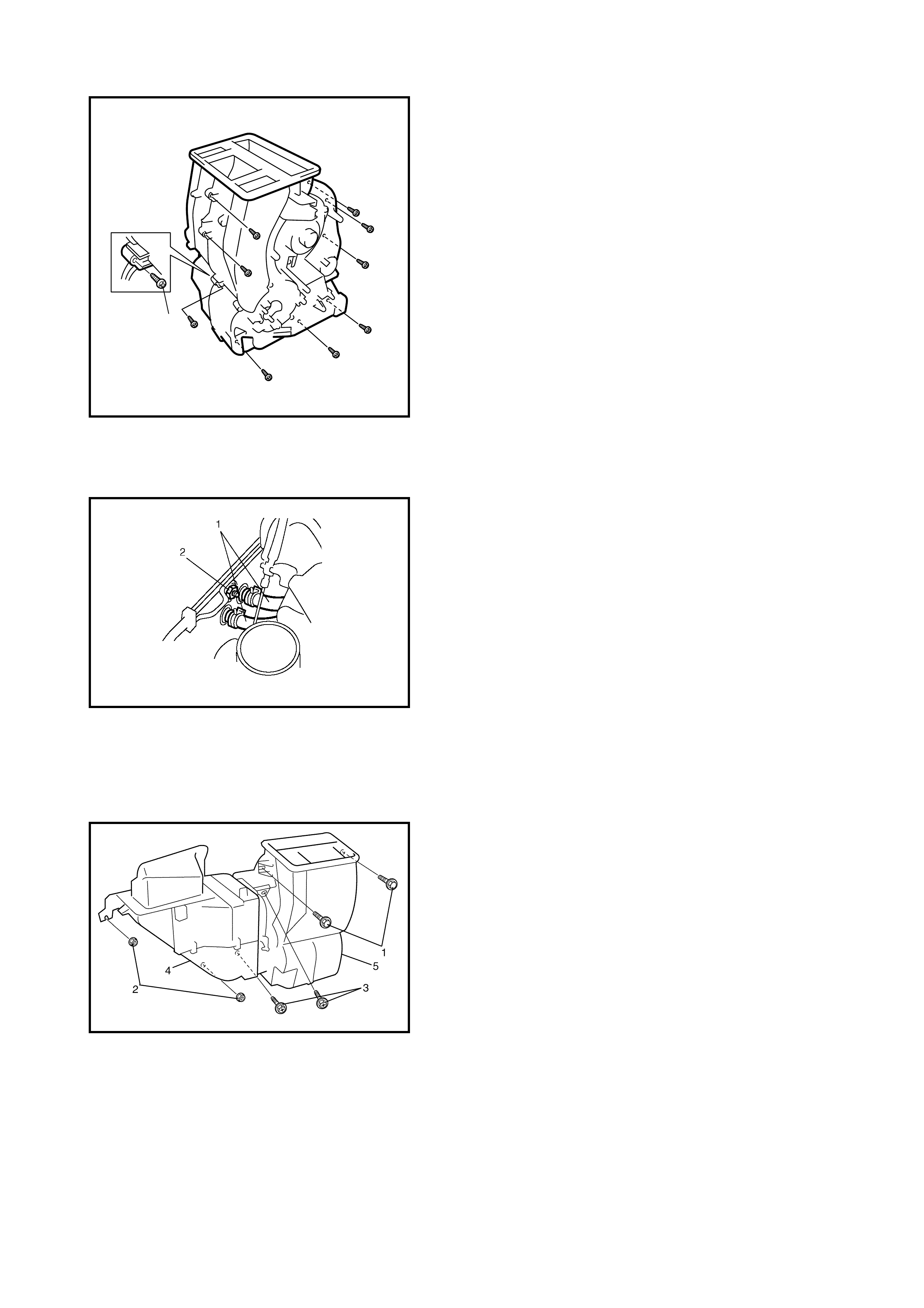
CAUTION: Sealing problems may occur when
disassembling and reassembling the heater case. If
the case leaks when reassembled, tighten with (1)
M4 x 16 self tapping screws (1) as shown in figure.
REMOVAL
1. Disconnect negative (–) cable at battery.
2. Drain engine coolant and disconnect heater hoses (1)
from heater unit.
3. Remove heater unit mounting nut (2).
4. Remove instrument panel, refer to Section 9,
3.1 INSTRUMENT PANEL REMOVAL.
5. Disconnect blower motor and resistor couplers from
heater unit.
6. Remove bolts (1), nuts (2) and screws (3) as shown.
7. Remove cooling unit (4) and heater unit (5) from
vehicle.
INSTALLATION
Reverse removal procedure to install heater unit noting the
following instructions.
• When installing each part, be careful not to catch any
cables or wiring harnesses.
• Adjust heater control cable, refer to 3.4 HEATER
CONTROL LEVER ASSEMBLY in this Section.
• Che ck coolant level and fill to correct level if required.
1
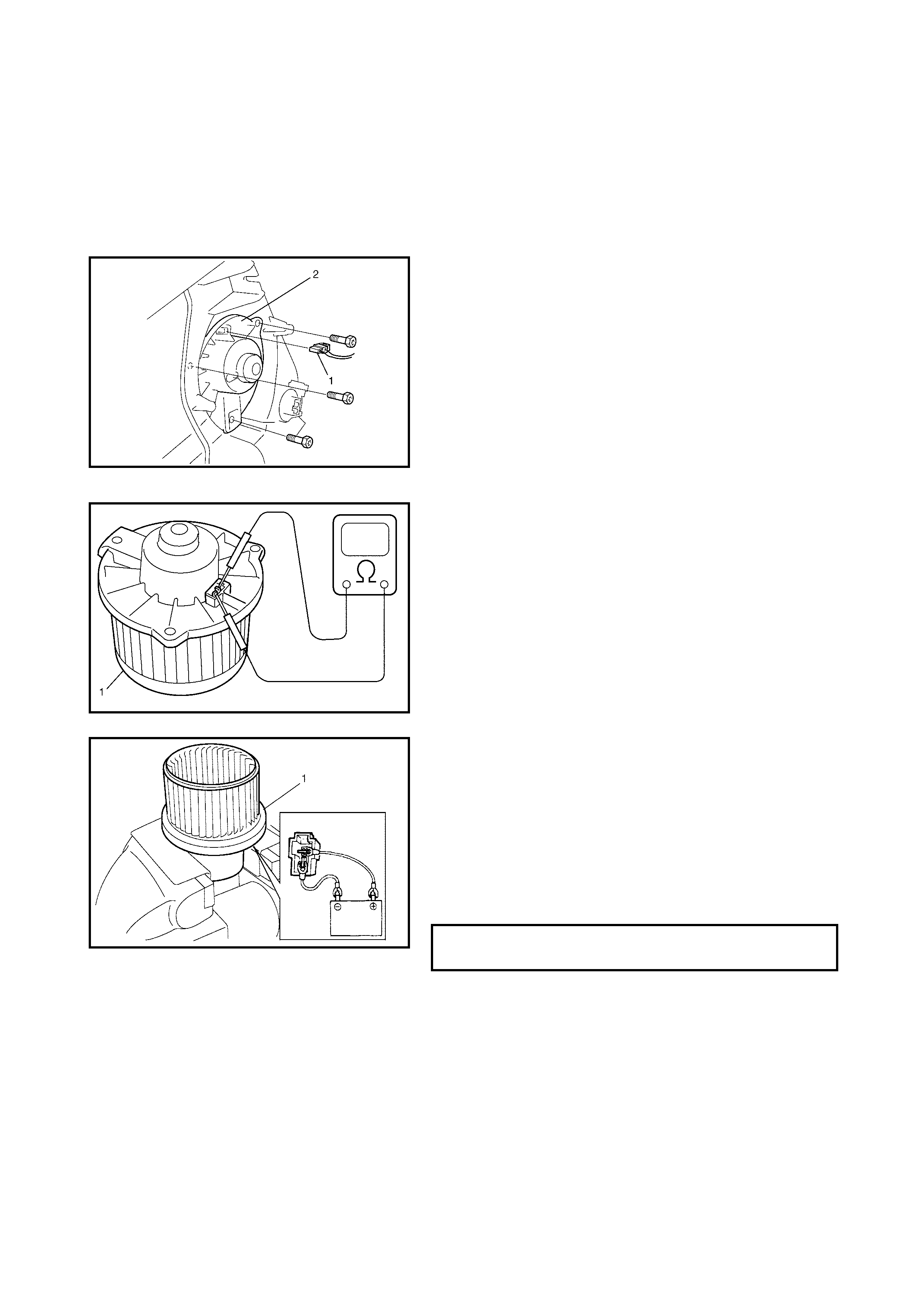
3.2 BLOWER FAN MOTOR
REMOVAL
1. Disconnect negative (–) cable at battery.
2. Remove steering column hole cover.
3. Remove brake and clutch pedal bracket from vehicle
body, refer to Section 7C, 3.2 CLUTCH PEDAL AND
CLUTCH PEDAL AND BRACKE T.
4. Disconn ect blower motor connector (1).
5. Remov e b lo wer f an motor (2).
INSPECTION
1. Check continuity between the two termi nals as shown.
If there is no continuity, replace blower fan motor
assembly (1).
2. Check operation and current flow.
a. Secure blower fan motor assemb ly (1) using a vice.
b. Connect battery to blower fan motor assembly (1)
as shown.
c. Check that blower fan motor operates smoothly
and there is no abnormal noise.
d. Check that amme ter indicates specified current.
If current measure is incorrect, replace blower fan
motor.
INSTALLATION
Reverse removal procedure for ins tallation.
BLO WER FAN SPECIFIED CURRENT
@ 12 VOLT 18 A MAX.
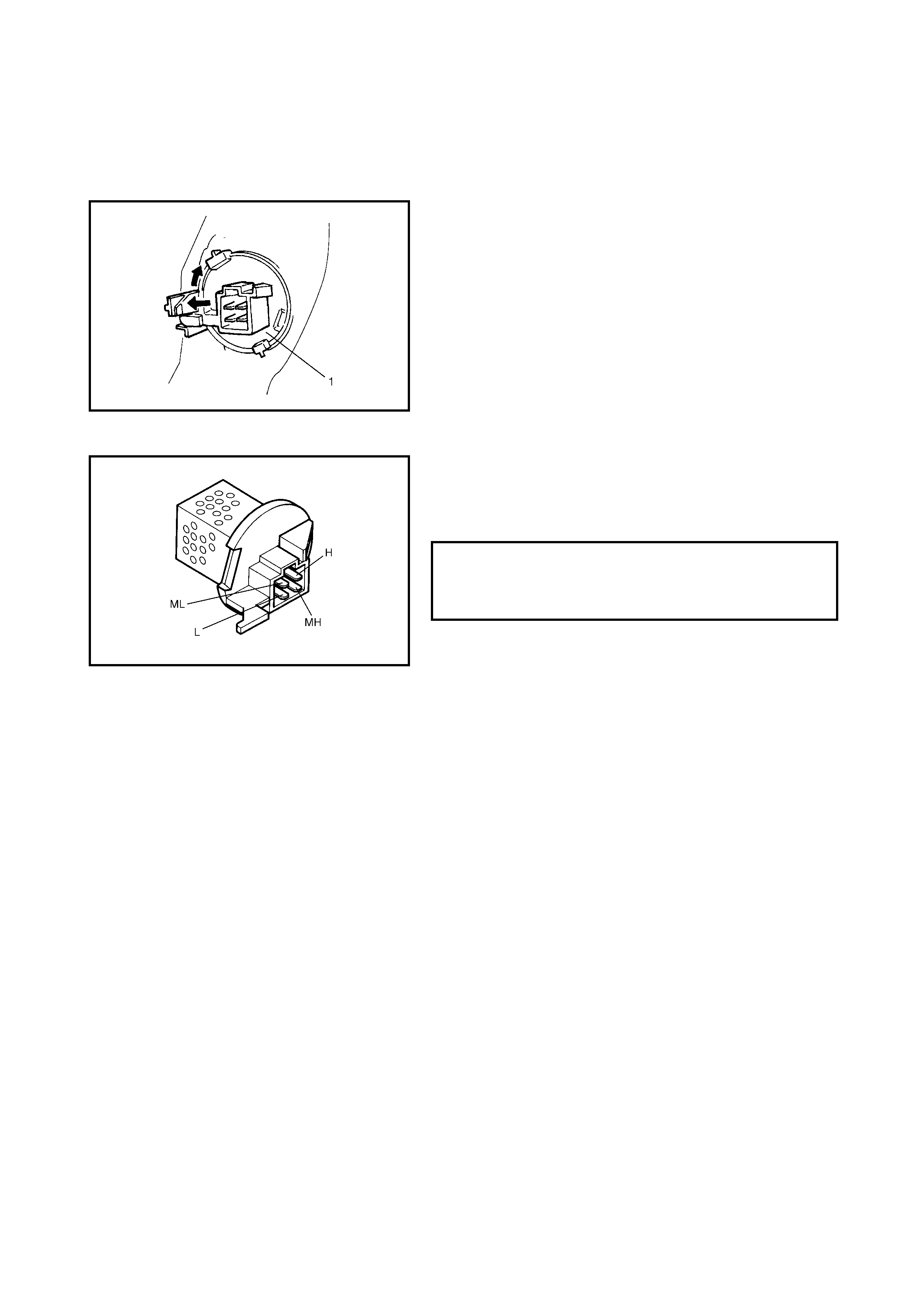
3.3 BLOWER FAN MOTOR RESISTOR
REMOVAL
1. Disconn ect negative (–) cab le at battery.
2. Disconnect blower f an motor resistor connector.
3. Remove bl ower fan motor resistor (1) as shown.
INSPECTION
Measure each terminal-to-terminal resistance on blower
motor resistor
If measured resistance is incorrect, replace blower motor
resistor.
INSTALLATION
Reverse removal procedure for ins tallation.
BLO WER FAN MOTOR RESISTANCE
H–MH (APPROX.)
H–ML (APPROX.)
H–L (APPROX.)
0.5 9 AT 25°C
1.5 9 AT 25°C
3.0 9 AT 25°C
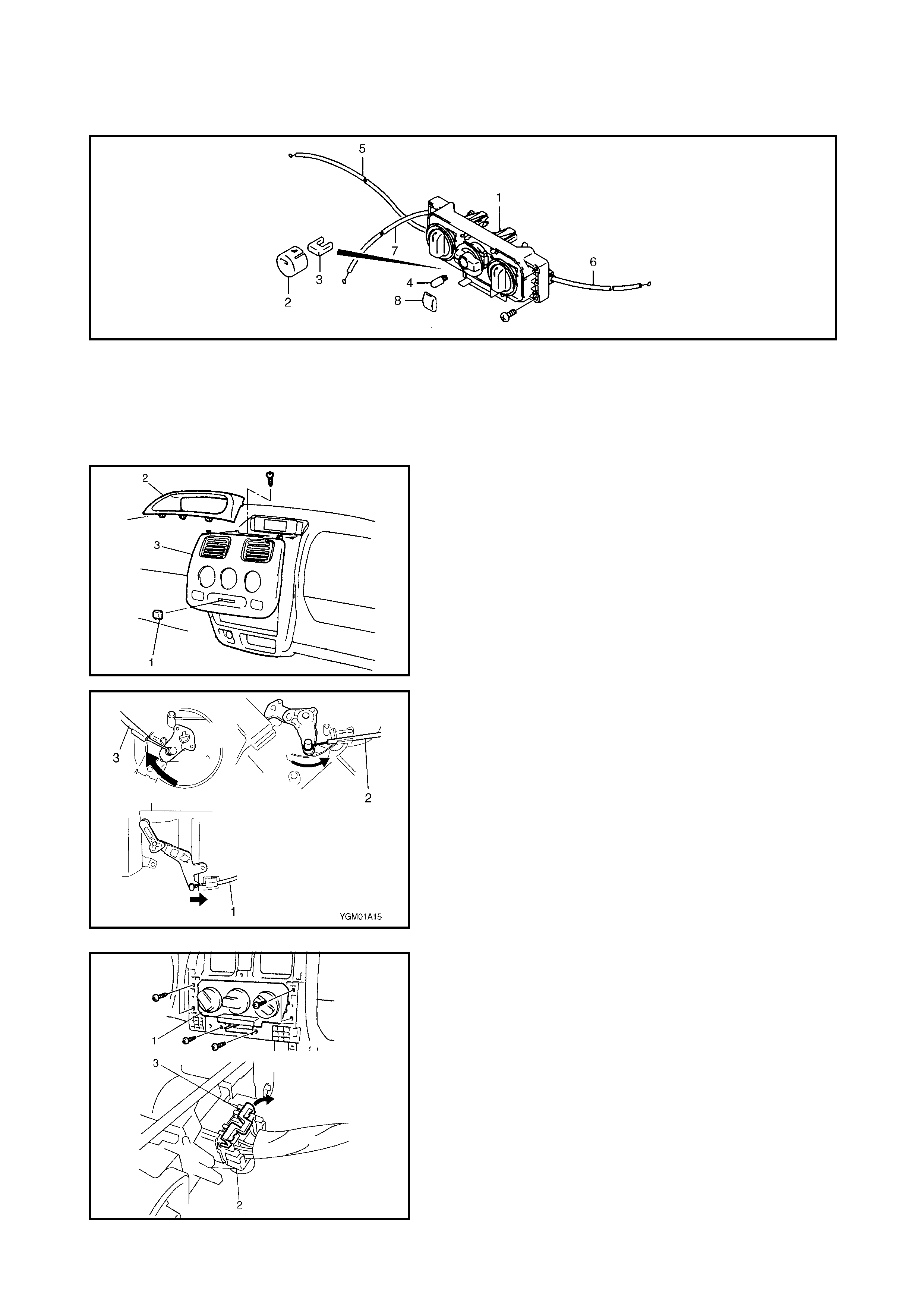
3.4 HEATER CONTROL ASSEMBLY
Legend
REMOVAL
1. Disconnect negative (–) cable at battery.
2. Remove steering column hole cover.
3. Remove heater control knob (1), centre upper console
surround (2) and centre lower console cover (3).
4. Remove glovebox, refer to Section 9,
3.1 INSTRUMENT PANEL.
5. Disconnect air outlet control cable (3), temperature
control cable (2) and fresh air control cabl e (1).
6. Remove heater control assembly (1), then unlock (3)
blower fan switch connector (2) and disconnect as
shown.
1. Heater control
assembly 3. A /C switch LED
(if equipped) 5. F resh air control
cable 7. Temperatu re
control cable
2. A/C switch knob
(if equipped) 4. B ulb 6. A ir outlet control
cable 8. Heater control knob
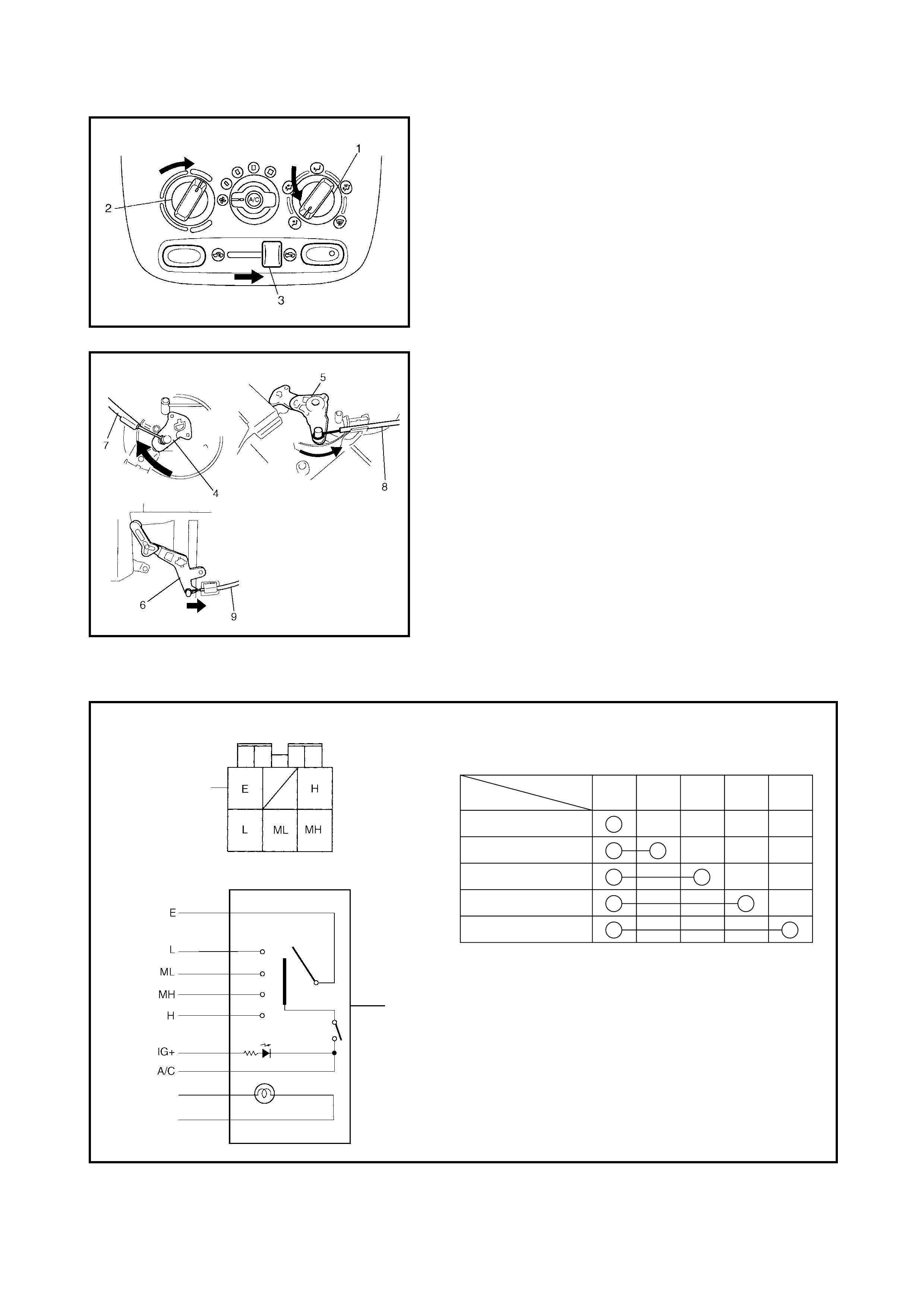
INSTALLATION
1. Reverse removal procedure for ins tallation.
2. Adju st the following items.
a. Move the air outlet control dial (1), temperature
control dial (2) a nd f resh air con trol lever (3) fully in
direction shown in figure.
b. Push air outlet lever (4), temperature lever (5) and
door link (6) fully in direction shown in figu re then fit
and clamp air outlet control cable (7), temperature
control cable (8) and fresh air control cable (9) as
shown in figure.
NOTE: After installing control cables, ensure that control
levers move smoot hly and stop in their correct positions.
INSPECTION
Check blower fan switch for each terminal-to-terminal continuity.
Legend
POSITIONTERMINAL E
OFF
L
ML
MH
H
LMLMHH
Circuit table of blower fan switch
1
2
ILM S/W
GND
1
1. Term ina l arrangement of blower fan sw itch 2. Blower fan switch
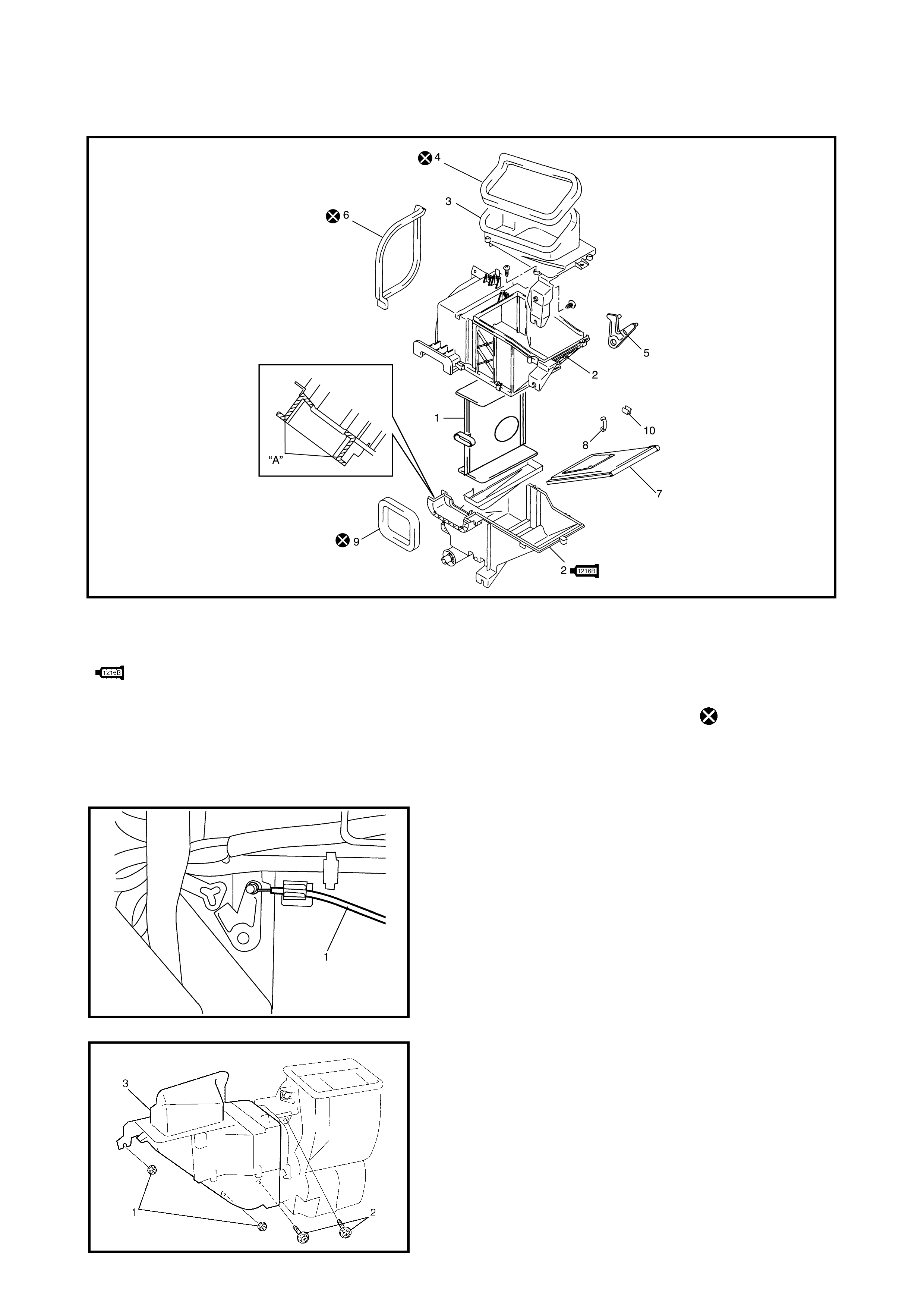
3.5 AIR INLET BOX
Legend
REMOVAL
NOTE: If vehic le is equipp ed with Air C onditi oning, refer to
Section 1B, 5.5 COOLING UNIT.
1. Disconnect negative (–) cable at battery.
2. Remove glovebox, refer to Section 9,
3.1 INSTRUMEN T PANEL .
3. Disable air bag system, refer to Section 10B,
3.1 SERVICE PREC A UT IO NS - DI SA BL ING
AIRBAG SYSTEM.
4. Disconnect fresh air control cable (1) from air inlet box.
5. Remove air inlet box mounting nuts (1) and screws (2).
6. Remove air inlet box (3).
1. Resistance board 3. Fresh air duct
case 5. Door link 8. Clip
2. Air inl e t case
: Apply Sealant Three Bond
1216 B to hatched part “A”
6. H eate r unit
packing 9. Dash packing
4. F res h air duct
pac k ing 10. Cable clamp
7. Air inlet door Do not reuse
INSTALLATION
Reverse removal procedure to install air inlet box noting the
following instructions.
• Adjust fresh air control cable, refer to 3.4 HEATER
CONTROL ASSEMBLY in this Section.
• Enable airbag system, refer to Section 10B,
3.1 SERVICE PREC A UT IO NS - EN ABLING
AIRBAG SYSTEM.
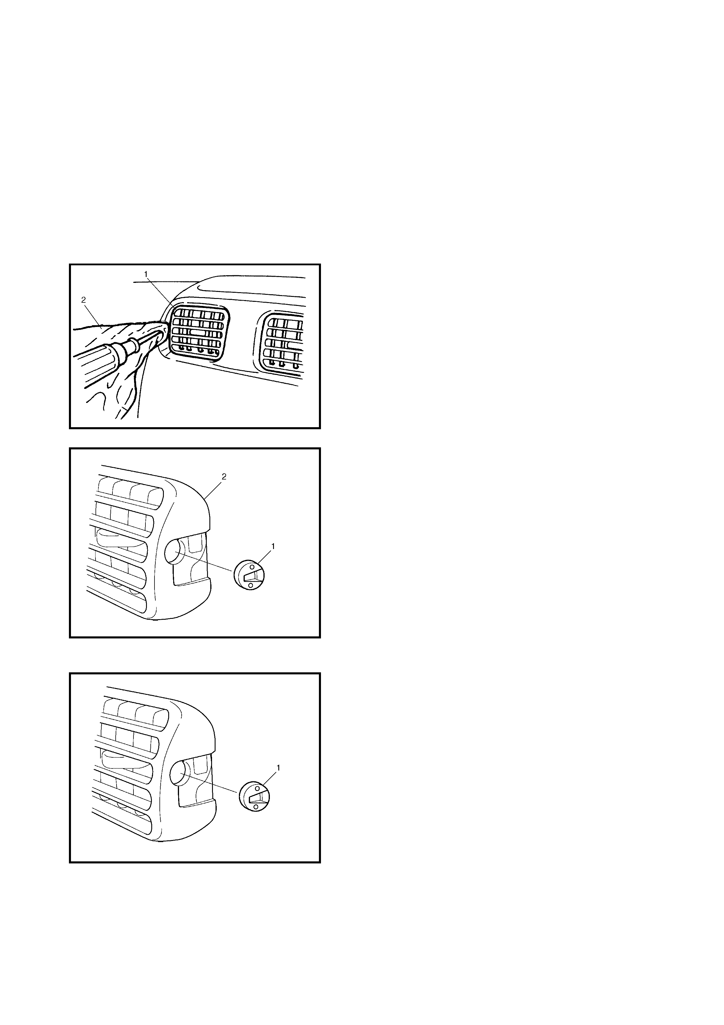
3.6 VENTILATION LOUVRE
REMOVAL
1. Remove ventilation louvre (1) using flat blade screw-
driver c ov ered with a r ag (2) for p ro tec tio n a s shown in
figure.
NOTE: Take care not to damage fascia.
2. Remove ventilation louvre holder (1) from ventilation
louvr e (2).
INSTALLATION
Reverse removal procedure to install ventilation louvre
noting the following instruction.
• Be sure to install ventilation louvre holder (1) in the
correct direction as shown.

4. REQUIRED SERVICE MATERIAL
Ma te ria l Recom m ende d Prod uct Use
Sealant Three Bond No. 1216B •Ai r in le t b ox