SECTION 10 - RESTRAINT SYSTEM
1. GENERAL DESCRIPTION
Seat Belt with A-ELR
Seat Belt with ELR and
Pretensioner
Driver and Front Passenger
Airbags
2. DIAGNOSIS
2.1 INSPECTION AND REPAIR
REQUIRED AFTER A COLLISION
3. ON-VEHICLE SERVICE
3.1 SERVICE PRECAUTIONS
Service and Diagnosis
Disabling Airbag System
Enabling Airbag System
Handling and Storage
Disposal
3.2 FRO NT SEAT BELT ASSE MBLY
Front Seat Belt
Seat Belt Switch
3.3 REAR SEAT BELT
Removal
Inspection
Installation
WARNING:
For vehicles equipped with Supplementary Restraint (Airbag) System:
• Service on and around the airbag system components or wiring must be performed only by an
authorised HOLDEN retailer. Refer to AIRBAG SYSTEM COMPONENTS and WIRING LOCATION
VIEW under GENERAL DESCRIPTION in Section 10B AIRBAG SYSTEM in order to confirm
whether you are performing service on or near the airbag system components or wiring. Please
observe all WARNINGS and SERVICE PRECAUTIONS under ON-VEHICLE SERVICE in Section
10B AIRBAG SYSTEM befo re performing servic e on or around the airbag system components or
wiring. Failure to f ollow WARNINGS could result in unintentional activation of th e system or could
render the system inoperative. Either of these two conditions may result in severe injury.
• Technical service work must be started at least 90 seconds after the ignition switch is turned to
the “LOCK” position and the negative cable is disconnected from the battery. Otherwise, the sys-
tem may be activated by reserve energy in the Sensing and Diagnostic Module (SDM).
CAUTION:
When fasteners are removed, always reinstall them at the same location from which they were
removed. If a fas te ne r ne ed s to b e re pl ac ed , use t he cor re ct pa rt numb er f as ten er for that ap pl i-
catio n. I f th e co rrec t p art numb er f as tene r is no t a vailab le, a fa sten er o f equ al size and st ren gth
(or stronger) may be used. Fasteners that are not reused, and those requiring thread-locking
compound, will be called out. The correct torque value must be used when installing fasteners
that require it. If the above procedures are not follow ed, parts or syste m damage could r esult.
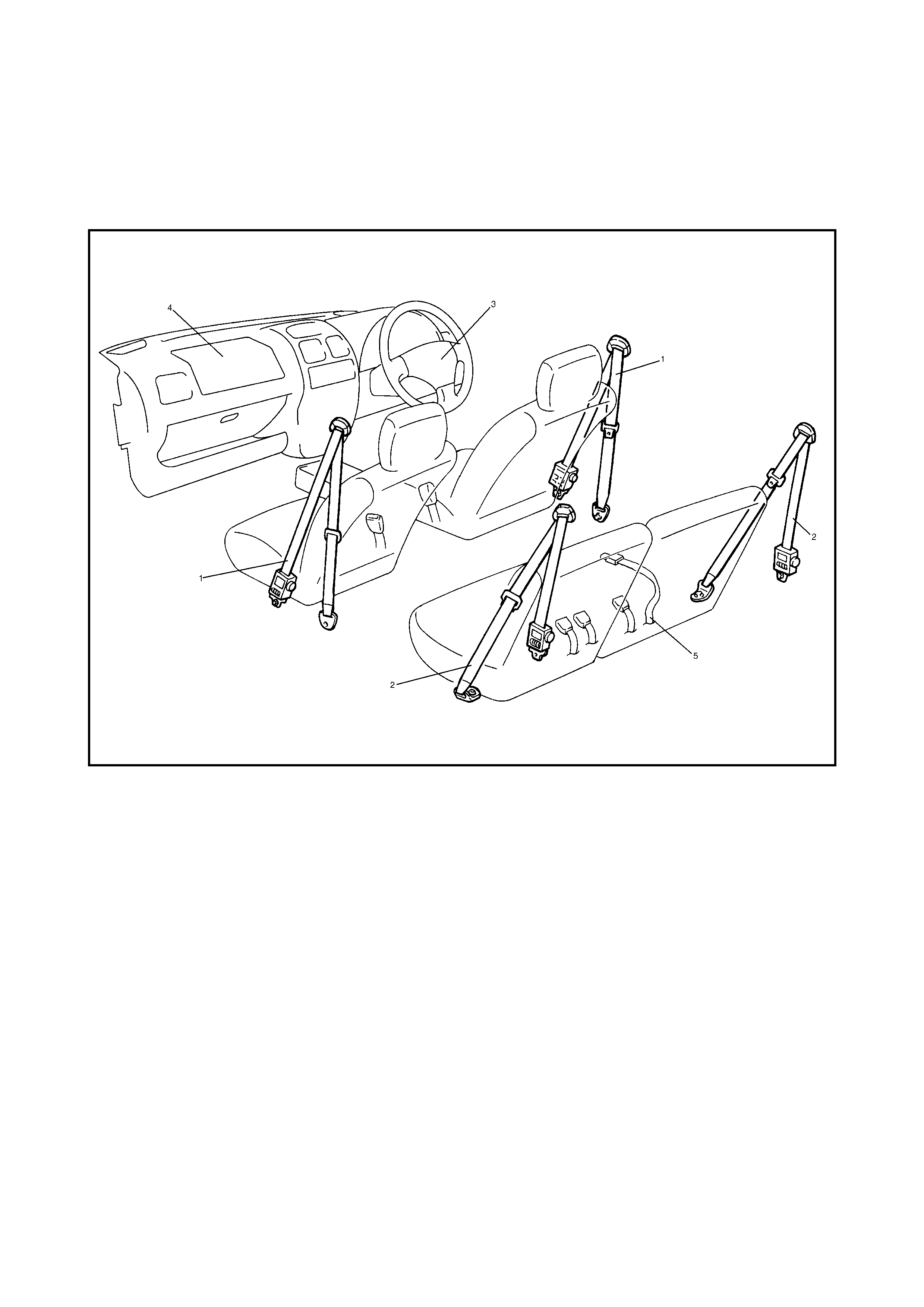
1. GENERAL DESCRIPTION
Legend
SEAT BELT WITH A-ELR
The automatic and emergency locking retractor (A-ELR) works as an Emergency Locking Retractor (ELR)
until the webbing is completely withdrawn and then as an Automatic Locking retractor (ALR) until it is fully
retracted.
ELR: Th e retractor mecha nism locks immed iately to preve nt fur ther sp ooling of the webbing when any of the
following are detected exceeding a set value:
• speed at which the webbing is pulled out of the retractor,
• acceleration or deceleration of the vehicle speed, and
• inclination.
ALR: Automatically l ock s the retractor when the webbing is withdrawn and then al lowed to re tract, even by a
small amount. Then the webbing cannot be withdrawn any further unless it is wound back fully into the retrac-
tor, which releases the lock and allows the webbing to be withdrawn.
SEAT BELT WITH ELR AND PRETENSIONER
The sea t belt with ELR and pret ensioner incor porates a prete nsioner mec hanism which operates in conjun c-
tion with the airbag system in addition to the abov e described ELR. The pretensioner takes up the slack of the
seat belt during a frontal collision with an impact greater than a predetermined value, thereby enhancing
restra int perfor man ce.
1. Front seat belt with ELR and pretensioner 4. Passenger airbag
2. Rear seat belt with A-ELR 5. Rear centre seat belt
3. Driver airbag

The pretensioner is incorporated in the retractor assembly and is controlled by the sensing and diagnostic
module (SDM) as one of the airbag system components. It will be activated at the same time as the airbag
when an impact at the front of vehicle exceeds the specified value.
When servicing the seat belt retractor assembly, observe all WARNINGS and CAUTIONS in this Section and
3. ON-VEHICLE SERVICE in Section 10B.
CAUTION: Do not reuse a seat belt pretensioner (retractor assembly) that has operated. It must
be replaced with a new assembly. For the checking procedure of its operation, refer to SERVICE
PRECAUTIONS in 3. ON-VEHICLE SERVICE in Section 10B.
DRIVER AND FRONT PASSENGER AIRBAGS
An airbag is provided for the driver and front passenger. During a frontal collision of a force greater than the
predetermined value, the driver’s airbag (inflator) module is deployed from the centre of the steering wheel
and the passenger’s airbag (inflator) module from the passenger side of the instrument panel, to supplement
the protection offered by the driver and front passenger seat belts and seat belt pretensioners.
2. DIAGNOSIS
For diagnosis of the airbag system and seat belt pretensioner, refer to Section 10B, AIRBAG SYSTEM.
2.1 INSPECTION AND REPAIR REQUIRED AFTER A COLLISION
After a collision, whether the seat belt pretensioner has been activated or not, perform checks and repairs
refer to Section 10B, 3.2 REPAIRS AND INSPECTIONS REQUIRED AFTER A COLLISION.
3. ON-VEHICLE SERVICE
3.1 SERVICE PRECAUTIONS
SERVICE AND DIAGNOSIS
WARNING: If replacing a seat belt, replace the buckle and ELR (or webbing) together as a set.
This is to ensure correct locking of the tongue plate with the buckle.
Failure to replace the components as a set may result in unreliable operation. For this reason,
replacement parts are supplied as a set.
Before servicing or replacing the seat belts, refer to the following precautionary items:
• Seat belts should be normal relative to strap retractor and buckle portions.
• Keep sharp edges and damaging objects away from belts.
• Avoid bending or damaging any portion of the belt buckle or latch plate.
• Do not bleach or dye belt webbing. Clean only with mild soap and lukewarm water.
• When installing a seat belt anchor bolt, it should be tightened by hand at first to prevent cross-threading
and then to specified torque.
• Do not attempt any repairs on retractor mechanisms or retractor covers. Replace defective assemblies
with new replacement parts.
• Keep belts dry and clean at all times.
• If the functionality of any parts is in question, replace these parts.
• Replace belts whose webbing is cut or otherwise damaged.
• Do not put anything into the trim panel opening which seat belt webbing passes through.
For a seat belt with pretensioner, refer to Section 10B, 3.1 SERVICE PRECAUTIONS.
WARNING: When performing service on or around airbag system components or airbag system wir-
ing, disable the airbag system. Refer to Section 10B, 3.1 SERVICE PRECAUTIONS. Failure to follow
procedures could result in possible airbag activation and personal injury.
DISABLING AIRBAG SYSTEM
Refer to Section 10B, 3.1 SERVICE PRECAUTIONS.
ENABLING AIRBAG SYSTEM
Refer to Section 10B, 3.1 SERVICE PRECAUTIONS.
HANDLING AND STORAGE
Refer to Section 10B, 3.1 SERVICE PRECAUTIONS.
DISPOSAL
Refer to Section 10B, 4. AIRBAG (INFLATOR) MODULE AND SEAT BELT PRETENSIONER DISPOSAL.
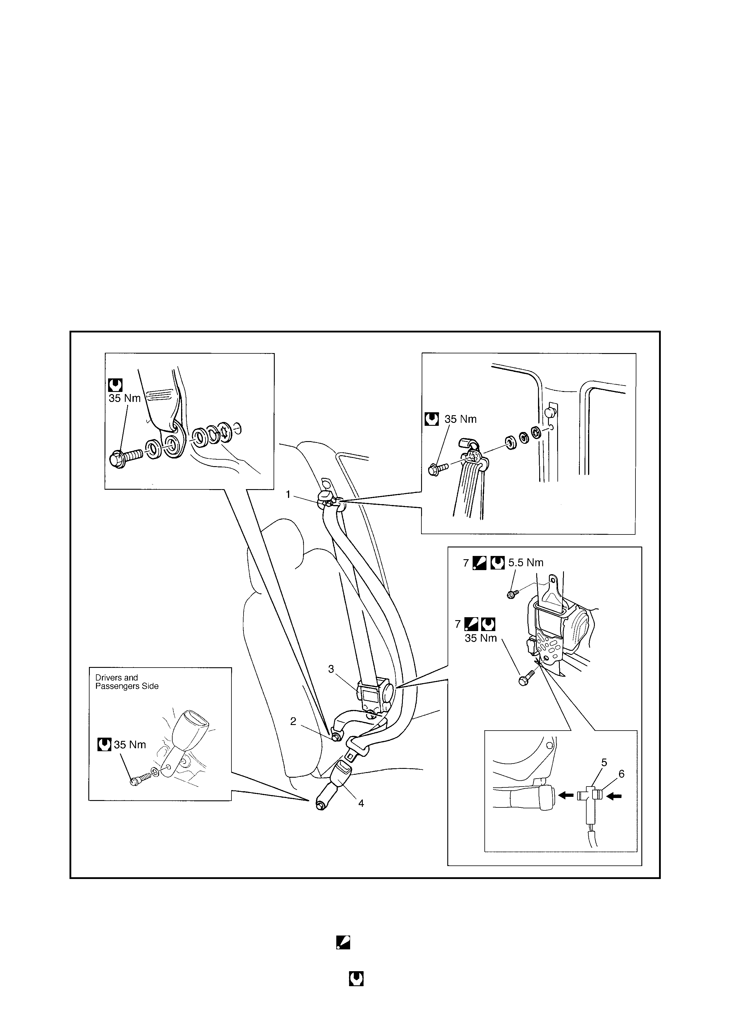
3.2 FRONT SEAT BELT ASSEMBLY
FRONT SEAT BELT
WARNING:
• Never attempt to disassemble or repair the seat belt pretensioner (retractor assembly). If any
abnormality is found, replace it with a new assembly.
• Read SERVICE PRECAUTIONS before starting work and observe every precaution during work.
Neglecting them may result in personal injury or inactivation of the seat belt pretensioner when
necessary.
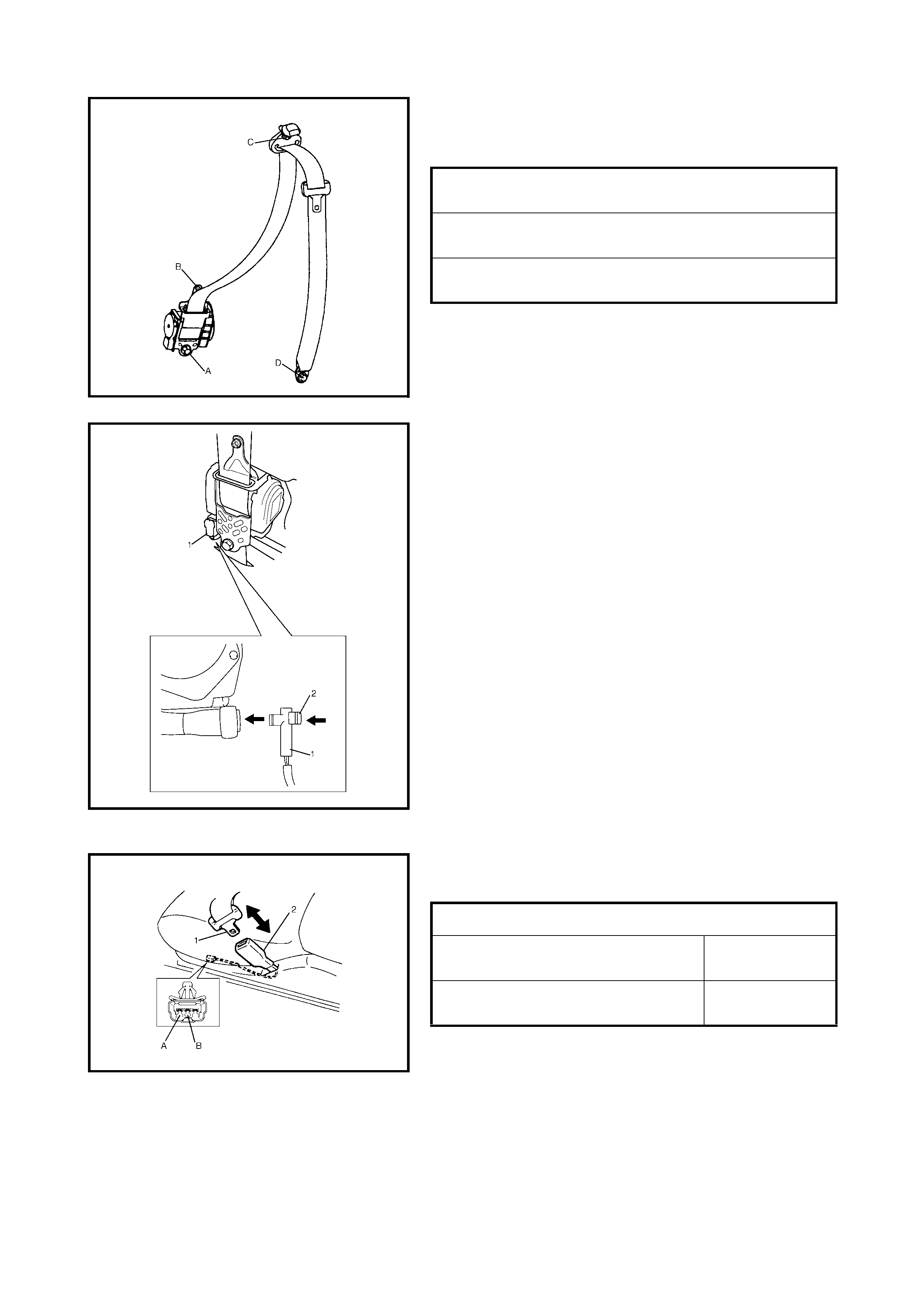
Legend
1. Upper anchor 5. Yellow connector f or seat belt pretensioner
2. Lower anchor 6. Lock slider
3. Retractor assembly 7. Retractor assembly mounting bolt:
After tightening lower bolt, tighten upper bolt
4. Buc kle Tightening torque
Removal
1. Disconnect negative battery cable at battery.
2. Disable the airbag system. Refer to Section 10B, 3.1 SERVICE PRECAUTIONS.
3. Remove the centre pillar lower trim.
4. Disconnect the Yellow connector for the seat belt pretensioner.
a. Release the lock slider.
b. After unlocking, disconnect the connector.
5. Remove the front seat belts and or buckles from the vehicle as shown in the figure on the previous page.
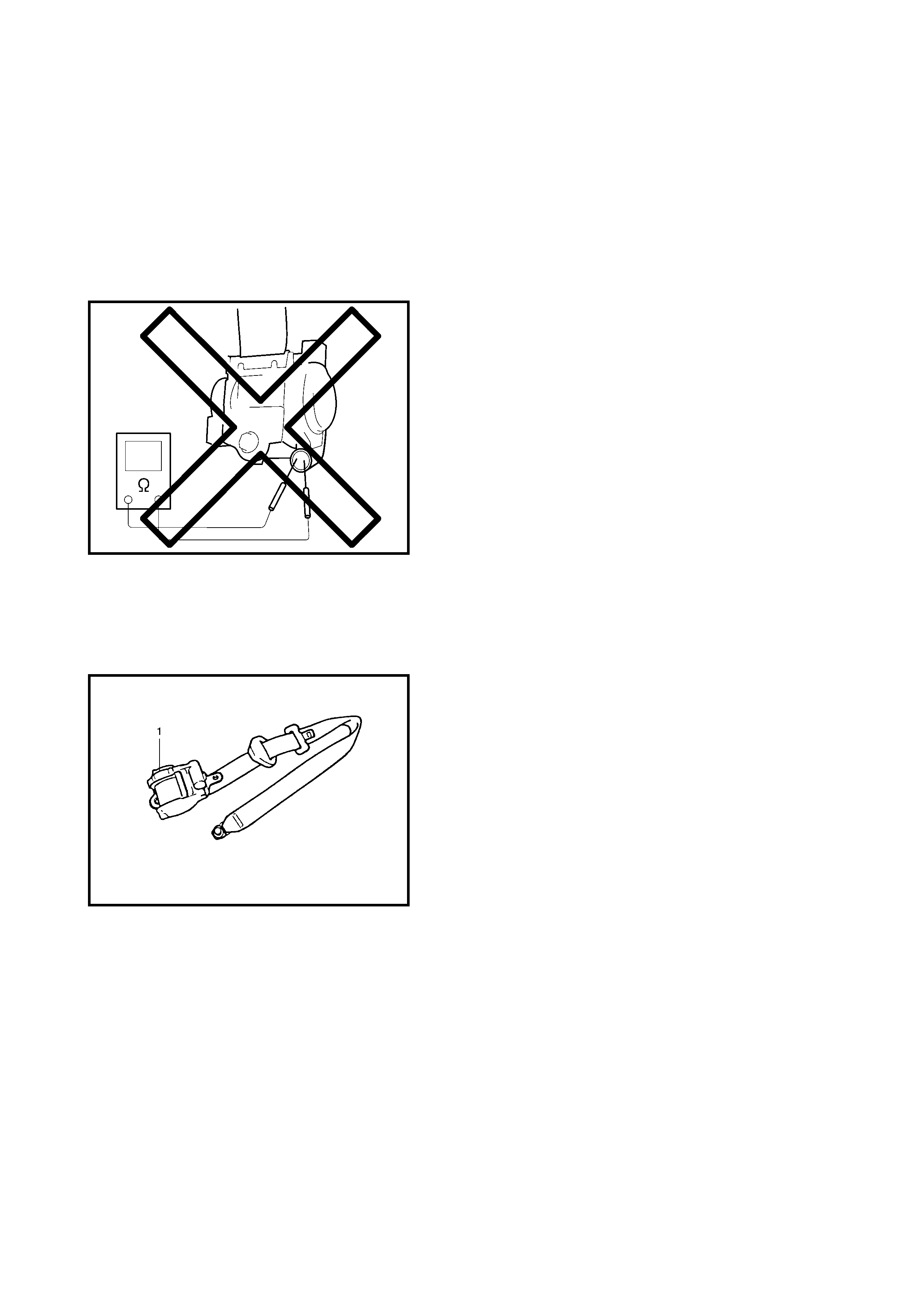
Inspection
WARNING: Never measure the resistance of a pre-
tensioner or disassemble it. Personal injury may
result.
CAUTION: If a seat belt pretensioner (retractor
assem bly) was droppe d it should be replaced.
Seat belts and attaching parts can affect the vital com-
ponents and systems of the vehicle. They should be
inspected carefully and replaced with genuine parts.
• Seat belt:
Its webbing or strap should be free from damage.
• Retractor assembly:
It should lock the webbing when pulled quickly.
The front seat belt retractor assembly (1) should pass
the above inspection and should lock webbing even
when tilted (appro x. 15°) toward the fore and aft or right
and left directions.
Check the appearance of the retractor assembly (1)
with seat belt pretensioner visually for following symp-
toms and if any one of them is applicable, replace it
with a new one as an assembly.
• Pretensioner has activated.
• There is a crack the in s eat bel t pretens ioner ( retractor
assembly).
• Wire harness or connector is damaged.
• Seat belt pretensioner (retractor assembly) is damaged
or a strong impact (e.g. dropping) was applied to it.
• Anchor bolt:
Anchor bolts should be torqued to specification.
• Belt latch:
It should be secure when latched.
Installation
Install in reverse order of removal, notin g the following:
• Seat belt anchor bolts should have an unified fine
thread (7/ 16-20 UNF). Under no circums tances shoul d
any different sized or metric screw threads be used.
• Tighten the bolts and screw in order A – D as
shown.
• Tighten the bolts and screw to the specified torque.
• Connect the Yellow connector (1) for the seat belt pre-
tensioner securely and fit the seat belt pretensioner
connector onto the body.
a. Insert the connector
b. Lock the connector with lock pin (2)
• Enable the airbag system. Refer to Enabling Airbag
System in 3.1 SERVICE PRECAUTIONS in Section
10B.
SEAT BELT SWITCH
Check the driver’s side seat belt strap switch for continuity
using an ohmmeter connected to terminals A and B.
RETRACTOR ASSEMBLY BOLT
TORQUE SPECIFICATION (A) 35 Nm
RETRACTOR ASSEMBLY SCREW
TORQUE SPECIFICATION (B) 5.5 Nm
UPPER & LOWER ANCHOR BOLT
TORQUE SPECIFICATION (C & D) 35 Nm
SEAT BELT STRAP SWITCH SPECIFICATION
WITHOUT BUCKLE TONGUE (1)
INSERTED INTO BUCKLE CATCH (2) CONTINUITY
WITH BUCKLE T ONGUE (1 ) INSER TED
INTO BUCKLE CATCH (2) NO CONTINUITY
3.3 REAR SEAT BELT
WARNING: Read SERVICE PRECAUTIONS before beginning work and observe all precautions during work.
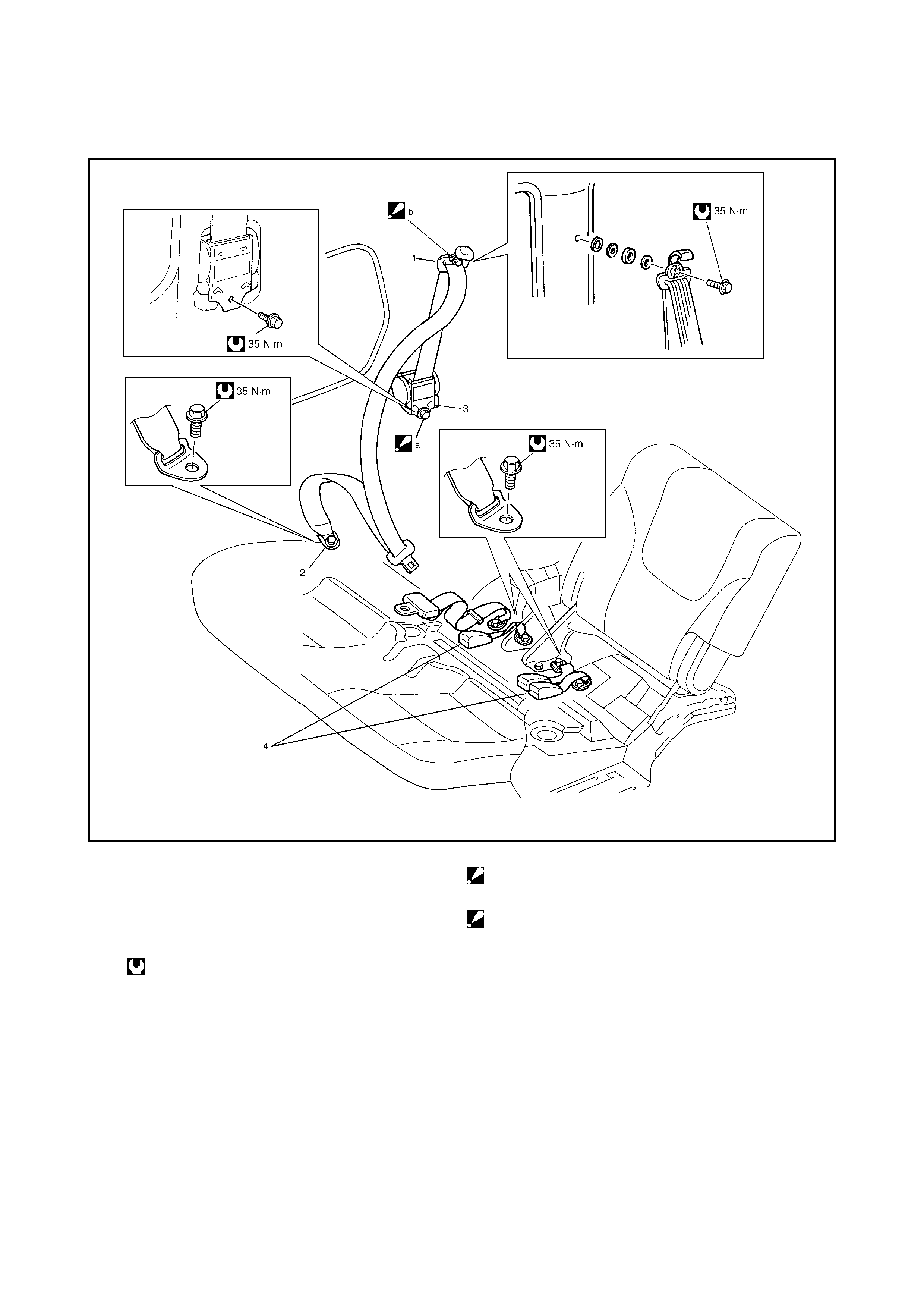
Legend
REMOVAL
1. If required, remove the rear seat cushion.
2. Remove the rear quarter panel interior trim.
3. Remove the rear seat belt(s) as shown in the figure.
INSPECTION
• The checks for the rear seat belt are the same as those for the front seat belts, refer 3.2 FRONT SEAT
BELT ASSEMBLY in this Section.
•For seat belts with A-ELR, in addition to the above check, check the following:
•With the vehicle stopped, withdraw the seat belt completely, let it retract slightly and then try to pull it out.
It should lock where it is.
•Let the seat belt retract to its original state. Withdraw it approximately half way, let it retract slightly and
then try to pull it out smoothly. It should not lock.
1. Upper anchor a. Retractor assembly mounting bolt:
Tightening order a – b
2. Lower anchor
3. Retractor assembly b. Upper anchor mounting bolt:
Tightening order a – b
4. Buckle
Tightening torque
INSTALLATION
Install in reverse order of removal, noting the following.
•Seat bel t anch or bo lts shou ld have an unifie d fine thread ( 7/16-2 0 UNF). U nder n o circ umsta nces sh ould
any different sized or metric screw threads be used.
•Tighten the bolts and screw in order A – B as shown.
•Tighten the bolts and screw to the specified torque.
RETRACTOR ASSEMBLY BOLT
TORQUE SPECIFICAT ION (a) 35 Nm
UPPER (b) & LOWER ANCHOR BOLT
TORQUE SPECIFICATION 35 Nm