
SECTION 10B - AIRBAG SYSTEM
1. GENERAL DESCRIPTION
1.1 SYSTEM COMPONENTS AND WIRING
LOCATION VIEW AND CONNECTORS
1.2 SYSTEM WIRING DIAGRAM
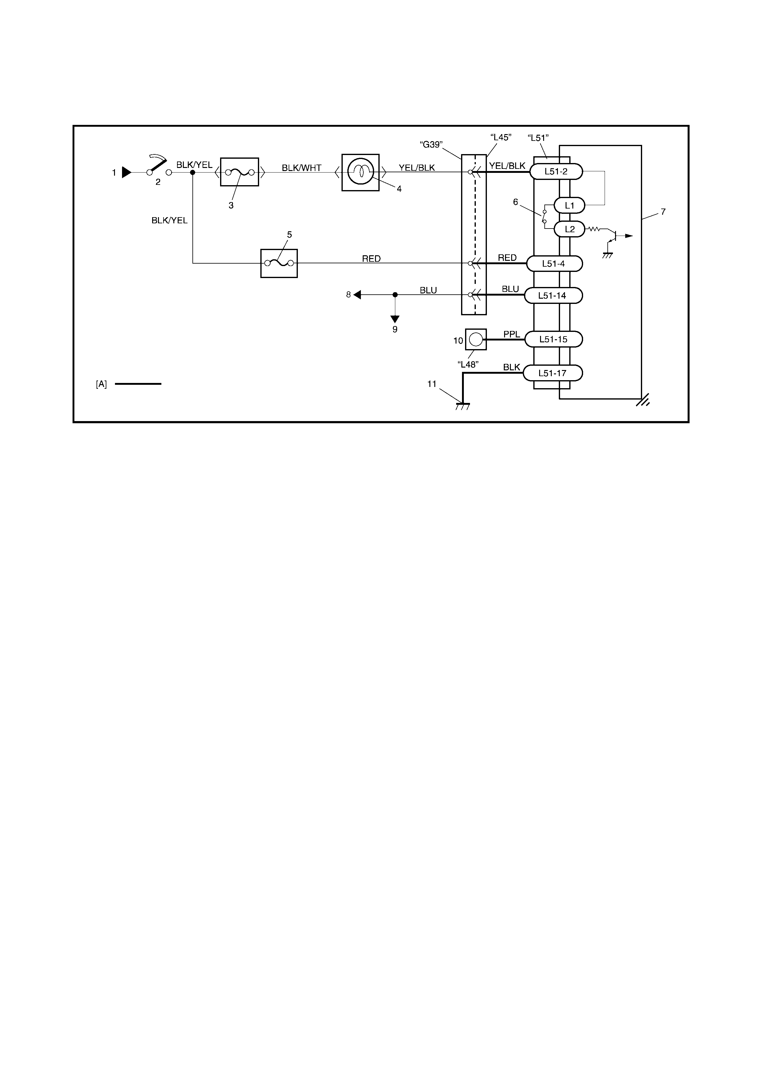
Terminal Arrangeme nt of SDM
Connector L51 (Viewed from
Harness Side)
2. DIAGNOSIS
2.1 DIAGNOSTIC TROUBLE CODE (DTC)
2.2 USE OF SPECIAL TOOLS
2.3 INTERMITTENTS AND POOR
CONNECTIONS
2.4 AIRBAG DIAGNOSTIC SYSTEM CHECK
2.5 AIRBAG DIAGNOSTIC SYSTEM CHECK
FLOW TABLE
2.6 DTC CHECK
2.7 DTC CLEARANCE
2.8 DTC TABLE
2.9 TABLE A - AIRBAG WARNING LAMP
COMES ON STEADY WITHOUT
FLASHING
2.10 TABLE B - AIRBAG WARNING LAMP
DOES NOT COME ON
2.11 TABLE C - AIRBAG WARNING LAMP
FLASHES
2.12 TABLE D - AIRBAG WARNING LAMP
CANNOT INDICATE FLASHING
Wiring Diagram
Table Test Description
Diagnostic Flow Table
2.13 TABLE E - SDM CANNOT
COMMUNICATE THROUGH THE
SERIAL DATA CIRCUIT
Wiring Diagram
Table Test Description
Diagnostic Flow Table
2.14 DTC B1015 - PASSENGER AIRBAG
INITIATOR CIRCUIT RESISTANCE
HIGH
2.15 DTC B1016 - PASSENGER AIRBAG
INITIATOR CIRCUIT RESISTANCE
LOW
WARNING:
For vehicles equipped with Supplemental Restraint (Airbag) System:
• Service on and around the airbag system components or wiring must be performed only by an
authorised HOLDEN retailer. Refer to AIRBAG SYSTEM COMPONENTS and WIRING LOCATION
VIEW under GENERAL DESCRIPTION in Section 10B AIRBAG SYSTEM in order to confirm
whether you are performing service on or near the airbag system components or wiring. Please
observe all WARNINGS and SERVICE PRECAUTIONS under ON-VEHICLE SERVICE in Section
10B AIRBAG SYSTEM before performing service on or around the airbag system components or
wiring. Failure to follow WARNINGS could result in unintentional activation of the system or could
render the system inoperative. Either of these two conditions may result in severe injury.
• Technical service work must be started at least 90 seconds after the ignition switch is turned to
the “LOCK” position and the negative cable is disconnected from the battery. Otherwise, the sys-
tem may be activated by reserve energy in the Sensing and Diagnostic Module (SDM).
• The procedures in this Section must be followed in the order listed to disable the airbag system
temporarily and prevent false diagnostic codes from setting. Failure to follow the procedures
could result in possible activation of the airbag system, personal injury or un-necessary repairs.
CAUTION:
Fasteners are important attaching parts that could affect the performance of vital components and
systems, and / or could result in major repair expense. They must be replaced with one of the same
part number of with an equivalent part if replacement becomes necessary.
Do not u se a repla cement part o f lesser q uality o r substi tute a d esign. Torque val ues must be used
as specified during reassembly to assure proper retention of these parts.
IMPORTANT:
Prior to connecting Tech 2 to the vehicle, refer to Section 0C TECH 2.

2.16 DTC B1018 - PASSENGER AIRBAG
INITIATOR CIRCUIT SHORT TO
GROUND
2.17 DTC B1019 - PASSENGER AIRBAG
INITIATOR CIRCUIT SHORT TO
POWER CIRCUIT
Wiri ng Diagra m
DTC Will Set When
Table Test Description
Diagnostic Flow Table
2.18 DTC B1021 – DRIVER AIRBAG
INITIATOR CIRCUIT RESISTANCE
HIGH
2.19 DTC B1022 – DRIVER AIRBAG
INITIATOR CIRCUIT RESISTANCE
LOW
2.20 DTC B1024 – DRIVER AIRBAG
INITIATOR CIRCUIT SHORT TO
GROUND
2.21 DTC B1025 – DRIVER AIRBAG
INITIATOR CIRCUIT SHORT TO
POWER CIRCUIT
Wiri ng Diagra m
DTC Will Set When
Table Test Description
Diagnostic Flow Table
2.22 DTC B1031 – POWER SOURCE
VOLTAGE HIGH
2.23 DTC B1032 – POWER SOURCE
VOLTAGE LOW
Wiri ng Diagra m
DTC Will Set When
Table Test Description
2.24 DTC B1041 – DRIVER PRETENSIONER
INITIATOR CIRCUIT RESISTANCE
HIGH
2.25 DTC B1042 – DRIVER RETENSIONER
INITIATOR CIRCUIT RESISTANCE
LOW
2.26 DTC B1043 – DRIVER PRETENSIONER
INITIATOR CIRCUIT SHORT TO
GROUND
2.27 DTC B1044 – DRIVER PRETENSIONER
INITIATOR CIRCUIT SHORT TO
POWER CIRCUIT
2.28 DTC B1045 – PASSENGER
PRETENSIONER INITIATOR CIRCUIT
RESISTANCE HIGH
2.29 DTC B1046 – PASSENGER
PRETENSIONER INITIATOR CIRCUIT
RESISTANCE LOW
2.30 DTC B1047 – PASSENGER
PRETENSIONER INITIATOR CIRCUIT
SHORT TO GROUND
2.31 DTC B1048 – PASSENGER
PRETENSIONER INITIATOR CIRCUIT
SHORT TO POWER CIRCUIT
Wiri ng Diagra m
DTC Will Set When
Table Test Description
Diagnostic Flow Table
2.32 DTC B1051 – FRONTAL CRASH
DETECTED (SYSTEM ACTIVATION
COMMAND OUTPUTTED)
DTC Will Set When
Table Test Description
2.33 DTC B1071 - INTERNAL SDM FAULT
DTC Will Set When
2.34 DTC – B1061 AIRBAG WARNING LAMP
CIRCUIT FAILURE
Wiring Diagram
DTC Will Set When
Table Test Description
Diagnostic Flow Table
3. ON-VEHICLE SERVICE
3.1 SERVICE PRECAUTIONS
Service And Diagnosis
Disabling Airbag System
Enab ling Airbag System
Handling And Storage
3.2 REPAIRS AND INSPECTIONS
REQUIRED AFTER A COLLISION
Collision With Deployment /
Activation – Component
Replacement
Collision With or Without
Deployment / Activation –
Component Inspections
3.3 SDM
Removal
Inspection
Installation
3.4 PASSENGER AIRBAG (INFLATOR)
MODULE
Removal
Inspection
Installation
3.5 DRIVER AIRBAG (INFLATOR) MODULE
3.6 CONTACT COIL AND COMBINATION
SWITCH ASSEMBLY
3.7 SEAT BELT PRETENSI ONER
4. AIRBAG (INFLATOR) MODULE AND SEAT
BELT PRETENSIONER DISPOSAL
4.1 DEPL O YME NT / ACT IVA T I ON OUTSID E
VEHICLE
4.2 DEPLOYMENT/ACTIVATION INSIDE
VEHICLE
4.3 DEPLOYED AIRBAG (INFLATOR)
MODULE AND ACTIVATED SEAT
BELT PRETENSIONER DISPOSAL
5. SPECIAL TOOLS
1. GENERAL DESCRIPTION
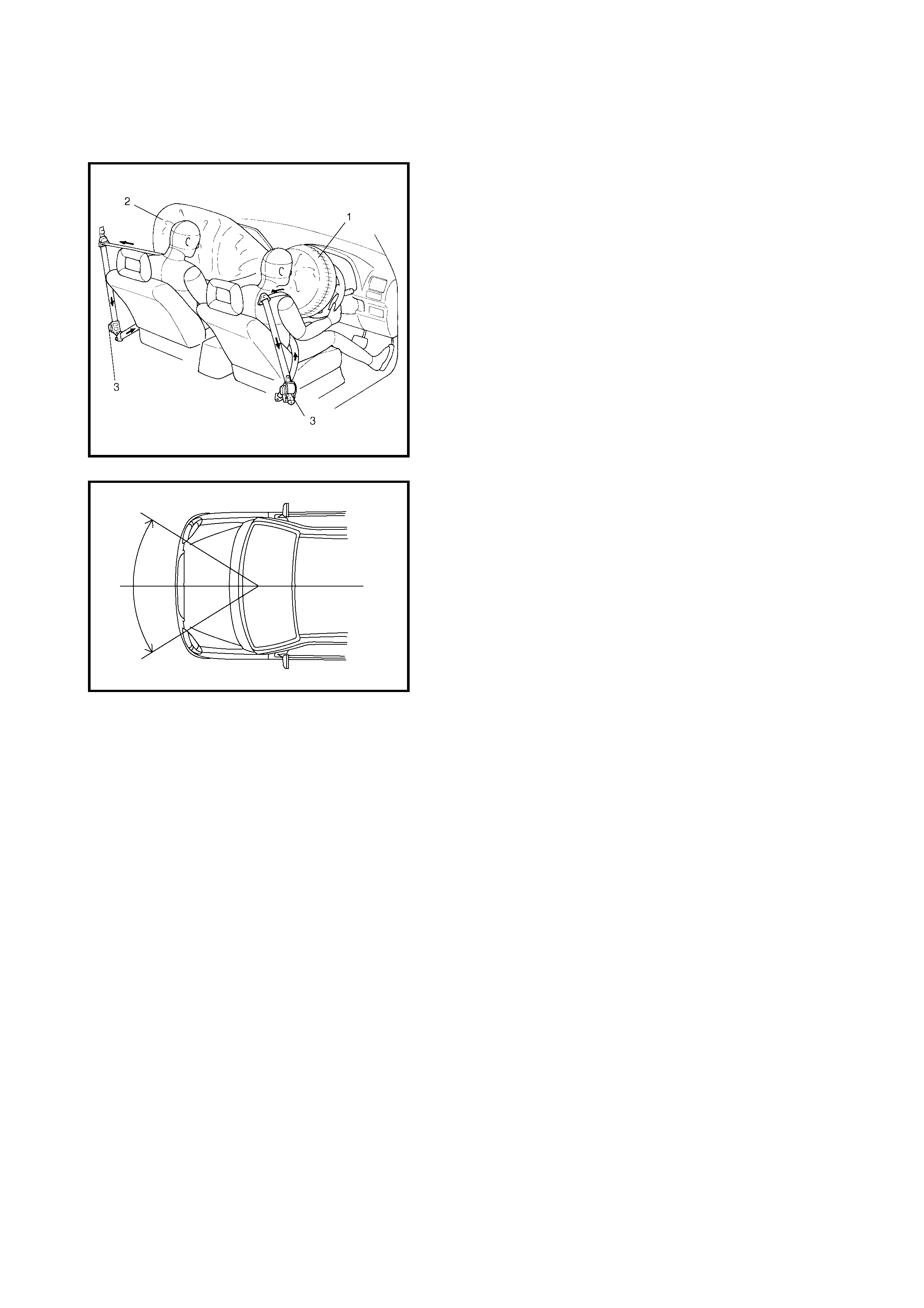
The airba g system includes air bags for both th e driver an d
front passenger as well as front seat belt pretensioners
which supplement the seat belts. During a frontal impact
greater than a certain value, the driver airbag (inflator)
module (1) is deployed from the centre of the steering
column, the passenger airbag (inflator) module (2) from the
front passenger side of the instrument panel and the seat
belt pretensioners (3) take-up the slack in the seat belts.
The airbag system is designed to activate only in severe
frontal collisions. It is not designed to activate in rear
impacts, side impacts, rollovers, or minor frontal collisions,
since it would offer no protection in those types of
accidents.
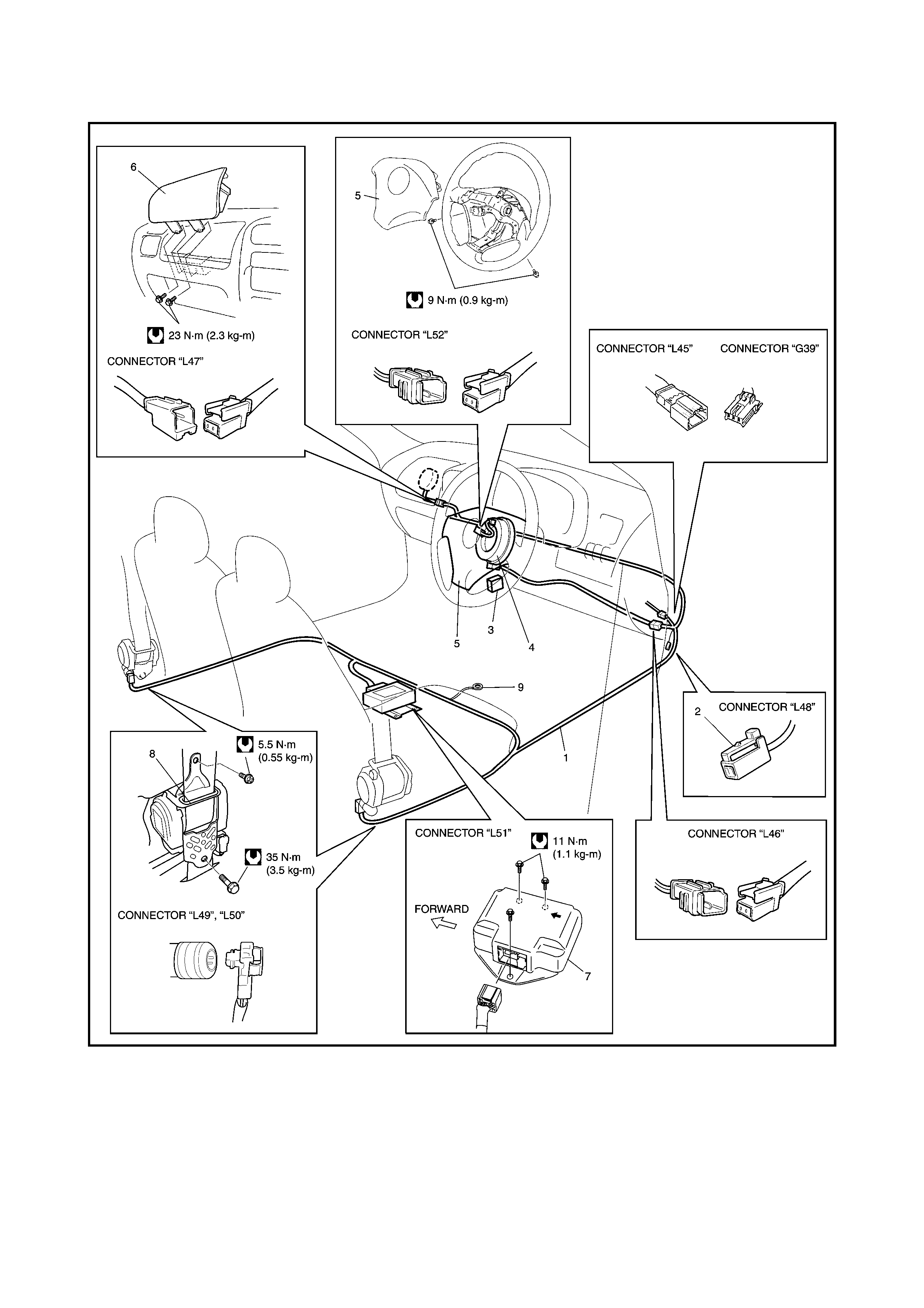
1.1 SYSTEM COM PONENTS AND WIRING LOCATION VIEW AND CONNECTORS
Legend
1. Airbag harness (in floor harness) 6. Passenger airbag (inflator) module
2. Airbag diagnosis connector No. 3 7. SDM
3. DLC 8. Seat belt pretensioner (retractor assembly)
4. Contact coil assembly 9. Ground for airbag system
5. Driver airbag (inflator) module
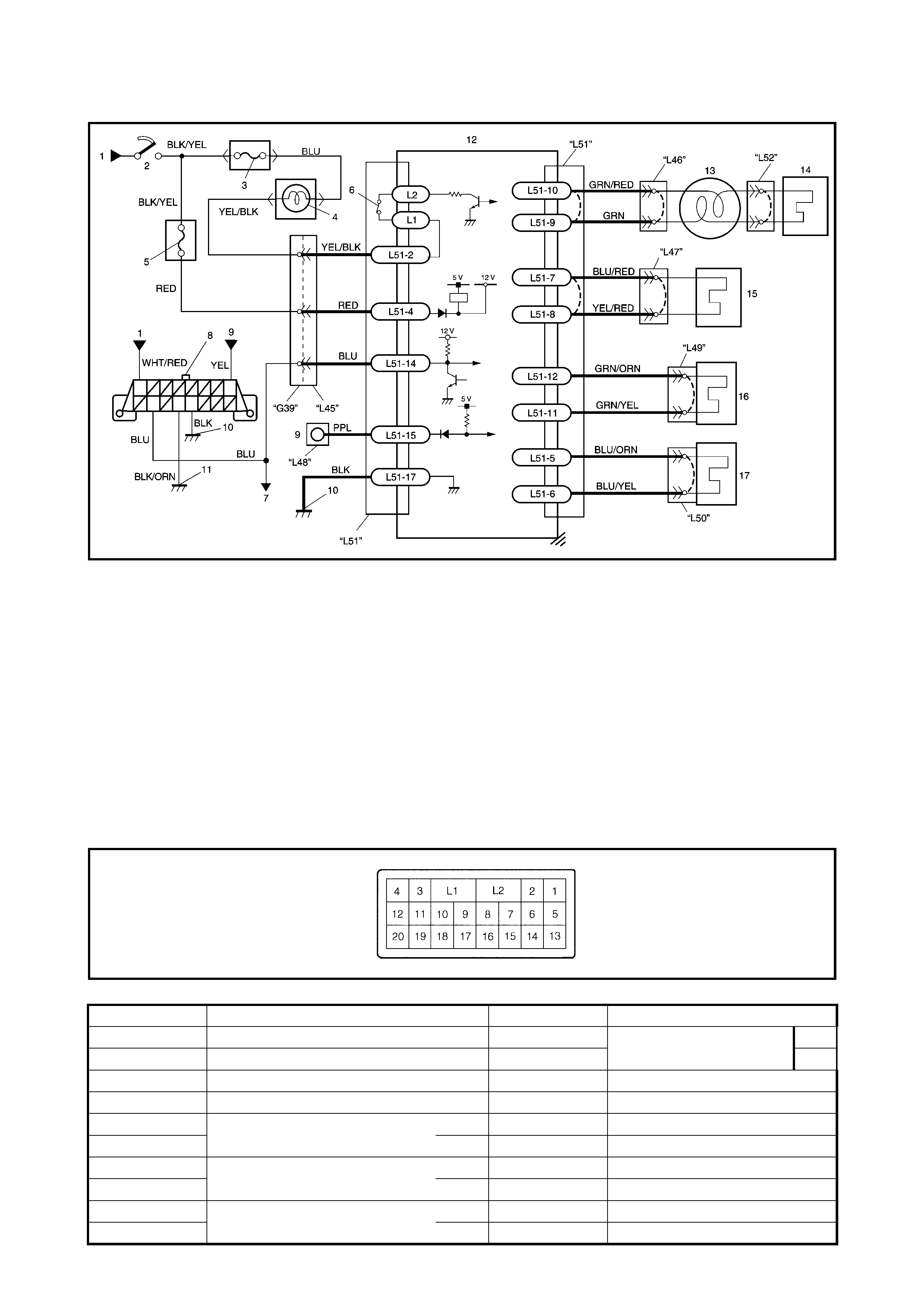
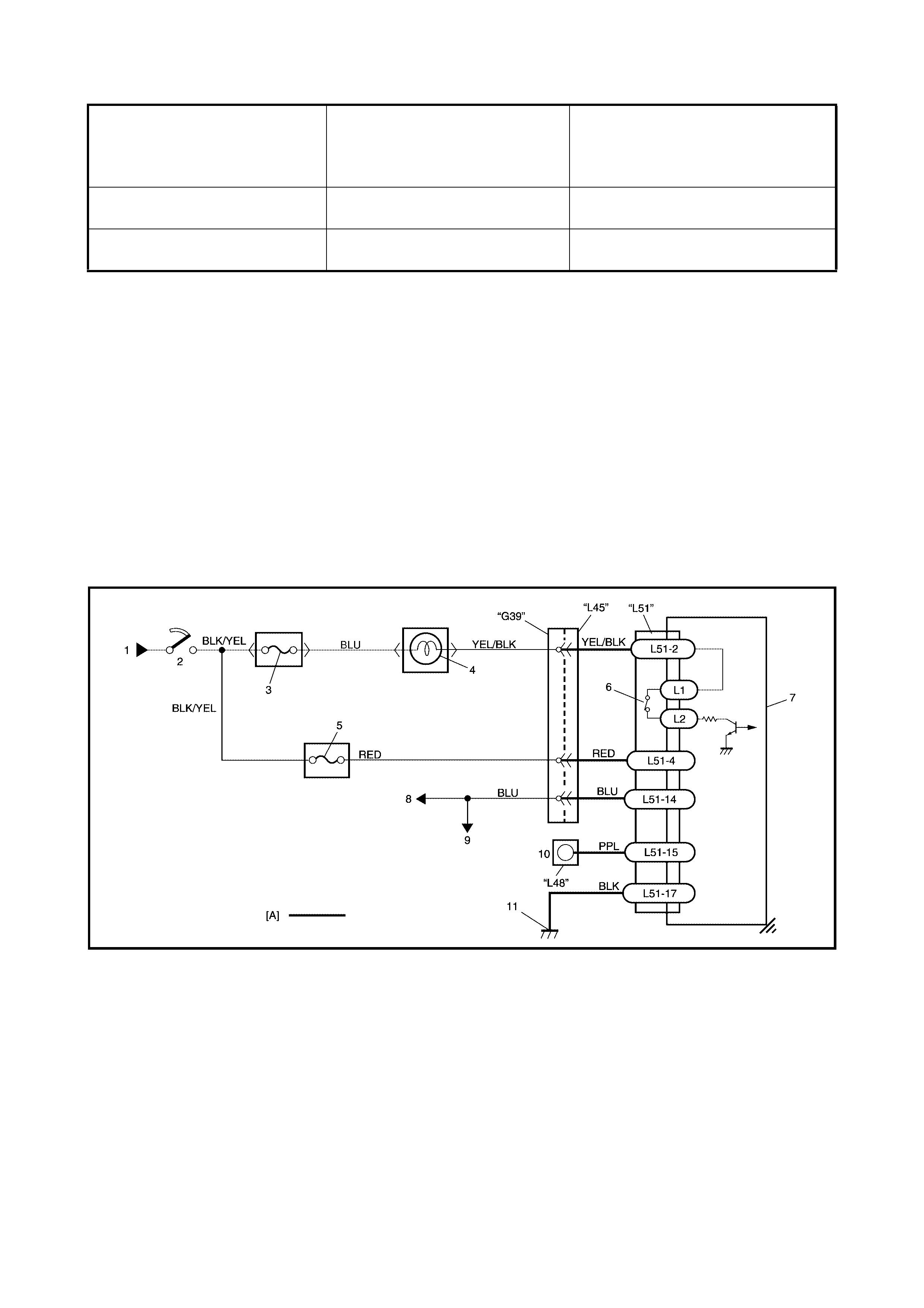
1.2 SYSTEM WIRING DIAGRAM
Legend
TERMINAL ARRANGEMENT OF SDM CONNECTOR L51 (VIEWED FROM HARNESS SIDE)
[A]: Shorting bar 8. Data link connector (DLC)
[B]: Airbag harness (in floor harness) 9. Airbag diagnosis connector No.3
[C]: Connector 10. Ground on body
1. From main fuse 11. Ground on engine block
2. Ignition switch 12. SDM
3. METER fuse 13. Contact coil assembly
4. AIRBAG warning lamp in combination meter 14. Driver airbag (inflator) module
5. AIRBAG fuse 15. Passenger airbag (inflator) module
6. Connection detection pin 16. Driver seat belt pretensioner
7. To ECM, TCM and ABS control module (if equipped) 17. Passenger seat belt pretensioner
TERMINAL CIRCUIT TERMINAL CIRCUIT
L51-1 – L51-11 Driver pretensioner Low
L51-2 AIRBAG warning lamp L51-12 High
L51-3 – L51-13 –
L51-4 Ignition switch (power source) L51-14 Data link connector (DLC)
L51-5 Passenger pretensioner
(if equipped) High L51-15 Diagno sis swi tc h
L51-6 Low L51-16 –
L51-7 Passenger airbag (inflator)
module High L51-17 Ground
L51-8 Low L51-18 –
L51-9 Driver airbag (inflator)
module Low L51-19 –
L51-10 High L51-20 –
2. DIAGNOSIS
WARNING: To avoid deployment when troubleshooting the airbag system, do not use electrical test
equipment such as a battery powered or AC powered voltmeter, ohmmeter, etc., or any type of electri-
cal equipment other than that specified. Do not use a non-powered probe type tester.
Instructions must be followed carefully, otherwise personal injury may result.
2.1 DIAGNOSTIC TROUBLE CODE (DTC)
The 2.4 AIRBAG DIAGNOSTIC SYSTEM CHECK must always be the starting point of any airbag system
diagnosis. The 2.4 AIRBAG DIAGNOSTIC SYSTEM CHECK checks for proper airbag warning lamp opera-
tion and checks for airbag Diagnostic Trouble Codes (DTCs) using on-board diagnosis function or Tech 2.
2.2 USE OF SPECIAL TOOLS
WARNING: To avoid deployment when troubleshooting the airbag system, do not use electrical test
equipment such as a battery powered or AC powered voltmeter, ohmmeter, etc., or any type of electri-
cal equipment other than that specified in this Service Information. Do not use a non-powered probe
type tester.
Instructions in this Service Information must be followed carefully, otherwise personal injury may
result.
You sh oul d be fam il ia r with the tools li st ed in this Se cti on un der the headi ng 5. SPE CIA L TOOLS . Yo u sh oul d
be a ble to measu re volta ge and resistan ce, and b e fa miliar with th e prop er use of a sc an too l such as air bag
Driver/Passenger Load Tool, Connector Test Adapter Kit and the Digital Multimeter.
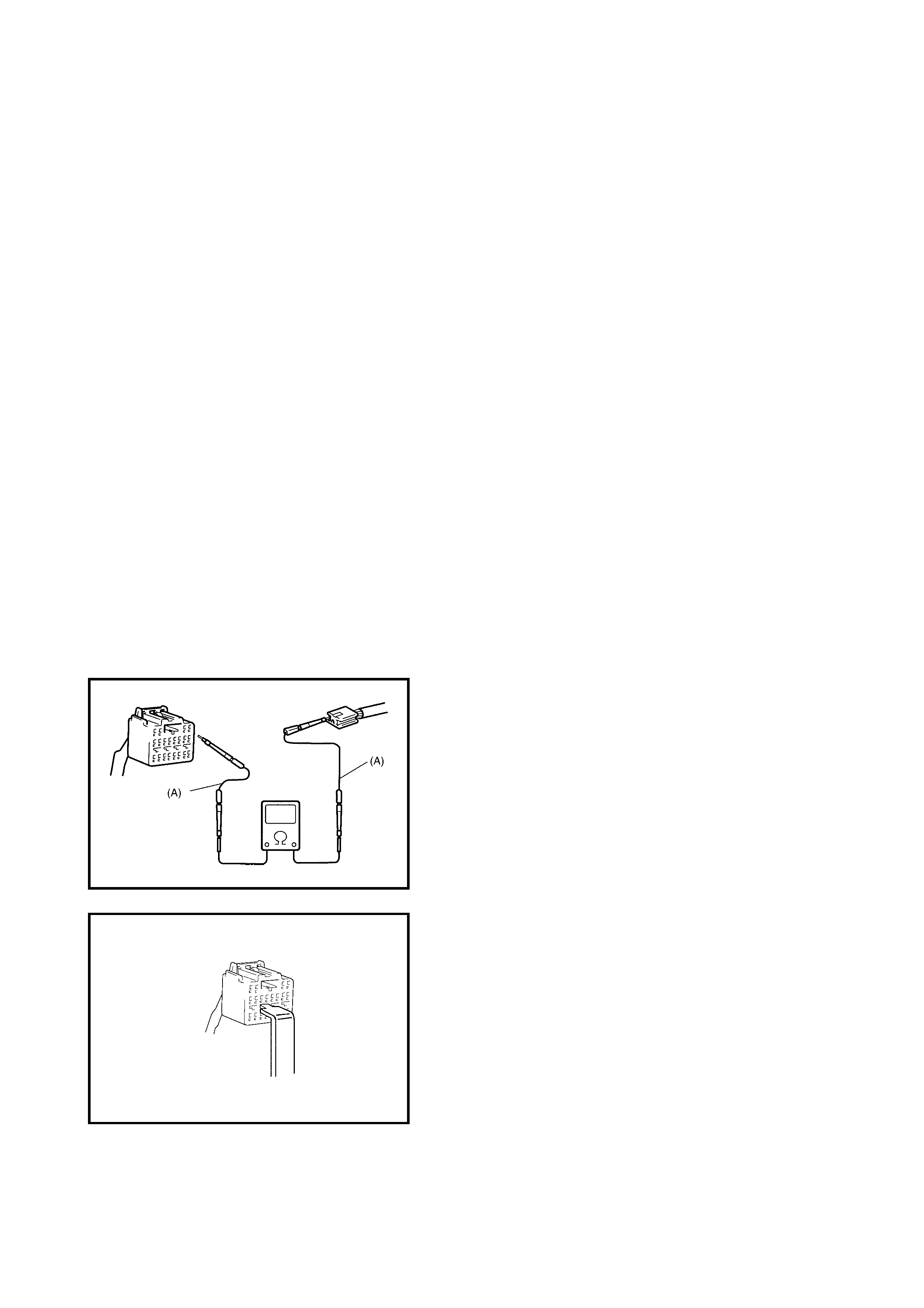
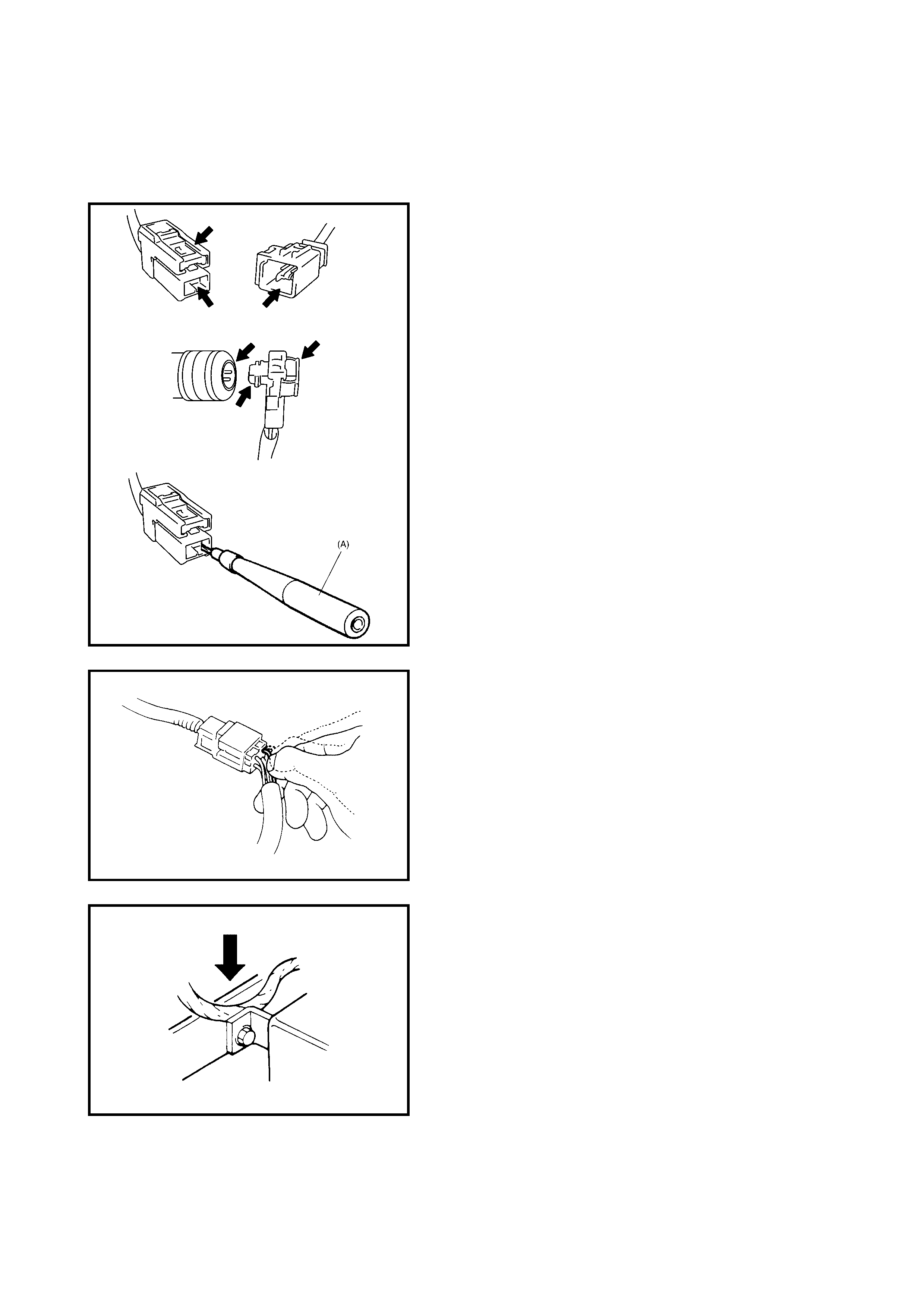
Special Tool (A) 09932-76010 Connector Test Adapter Kit
must be used whenever a diagnostic procedure requests
checking or probing a terminal.
Using the appropriate adapter in the special tool will ensure
that no damage to the terminal will occur from the
multimeter probe, such as spreading or bending.
An SDM sho rt bar release too l is include d in the connector
test adapter kit.
Inserti ng it in to the SDM conn ec tor will releas e the sh ortin g
bar.
The adapter will also give an idea of whether contact
tension is sufficient, helping to find an open or intermittent
open due to poor terminal contact.
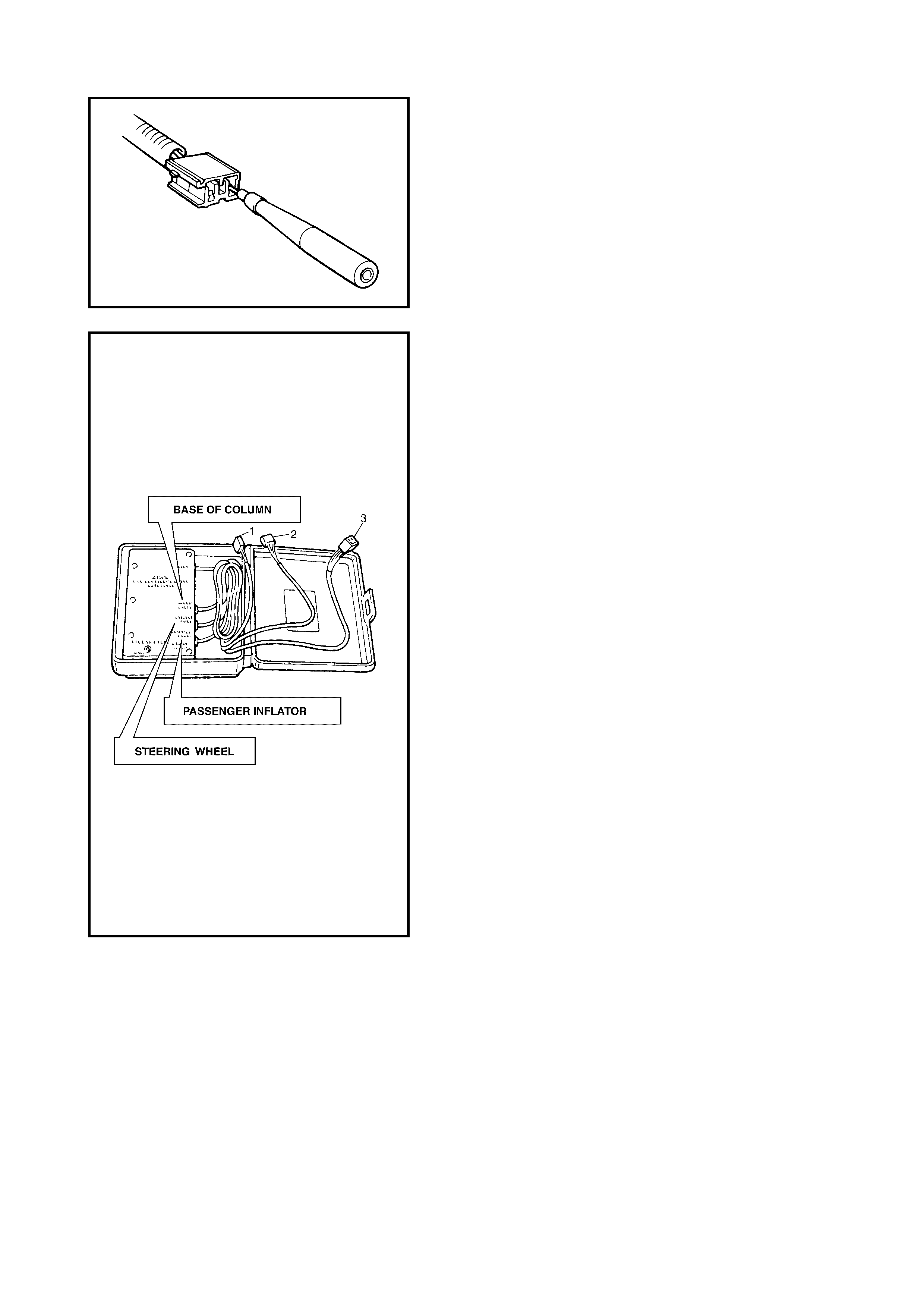
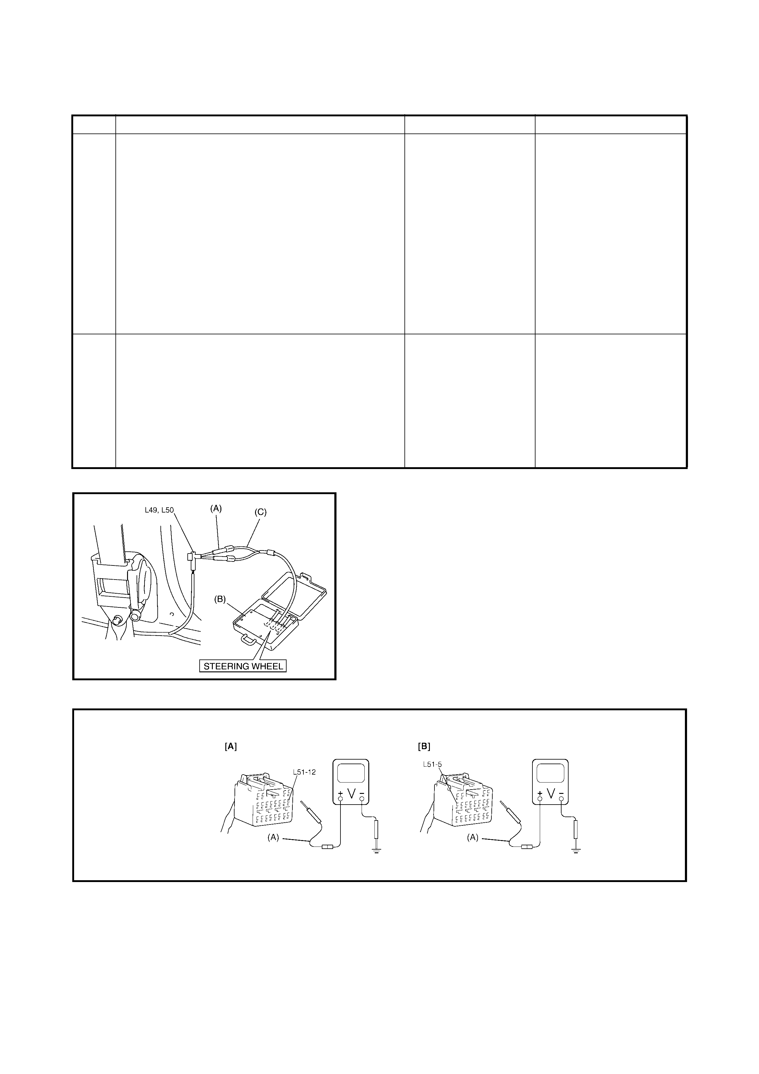
Special tool (B): 09932-75010 airbag driver/passenger load
tool is used only when called for in this Section. It is used
as a diagnostic aid and safety device to prevent inadvertent
airbag (inflator) module deployment.
The load tool has three connectors attached to its case
which are elect rically f unctional and s erve as resisti ve loa d
substitutions.
No more than two connectors are used at any time.
One of connectors (STEERING WHEEL) (2) is used to
substitute the load of followings:
• Driver airbag (inflator) module when it is connected at
the top of the column to the contact coil assembly.
• Passenger airbag (inflator) module when it is
connected to the airbag harness connector for
passenger airbag (inflator) module.
• Each of the driver and passenger seat belt
pretensioners when it is connected to the floor harness
connector for the driver and passenger seat belt
pretensioners.
Another connector (BASE OF COLUMN) (1) is used to
substitute the load of the driver airbag (inflator) module and
the contact coil as sembly whe n it is co nnected at the base
of the column to the airbag wire harness.
The third connector (PASSENGER INFLATOR) (3) is not
used.
By substituting the resistance of the load tool when called
for, a determi nation can be made as to whether an i nflator
circuit component is causing system malfunction and which
component is causing the malfunction.
The load tool should be used only when specifically called
for in the diagnostic procedures.
2.3 INTERMITTENTS AND POOR CONNECTIONS
Most intermittents are caused by faulty electrical
connec tio ns o r wirin g. W hen a c hec k f or pr ope r con nec tio n
is requested in a diagnostic flow table, perform careful
check of suspect circuits for:
• Poor ma ting of conn ector halves, o r terminals no t fully
seated in the connector body (backed out).
• Dirt or corrosion on the terminals. The terminals must
be clean and free of any foreign material which could
impede proper terminal contact.
However, cleaning the terminal with a sand paper or
the like is proh ibit ed .
• Damaged connector body, exposing the terminals to
moisture and dirt, as well as not maintaining proper
terminal orientation with the component or mating
connector.
• Improperly formed or damaged terminals.
Check each connector terminal in problem circuits
carefully to ensure good contact tension by using the
corresponding mating terminal included in the
connector test adapter kit (A) 09932-76010.
If contact tension is not enough, reform it to increase
contact tension or replace.
• Poor terminal -to- wir e co nnecti on.
Check each wire harness in problem circuits for poor
connection by shaking it by hand lightly. If any
abnormal condition is found, change the wire harness
assembly or component parts with new ones.
• Wire insulation which is rubbed through, causing an
intermit tent sh ort as the bare ar ea touc he s othe r wirin g
or parts of the vehicle.
• Wire broken inside the insulation. This condition could
cause a continuity check to show a good circuit, but if
only 1 or 2 strands of a multi-strand-type wire are
intact, resistance could be far too high.
If any abnormality is found, repair or replace as a wire
harness assembly.

2.4 AIRBAG DIAGNOSTIC SYSTEM CHECK
WARNING: To avoid deployment when troubleshooting the airbag system, do not use electrical test
equipment such as a battery powered or AC powered voltmeter, ohmmeter, etc., or any type of
electrical equipment other than that specified in this Service Information. Do not use a non-powered
probe type tester.
Instructions in this Service Information must be followed carefully, otherwise personal injury may
result.
CAUTION:
The order in which diagnostic trouble codes are diagnosed is very important. Failure
to diagnose the diagnostic troubl e codes in the order specified may result in extended
diagnostic time, incorrect diagnosis and incorrect parts replace ment.
The diagnostic procedures used in this Section are designed to find and repair airbag system malfunctions.
To get the best results, it is important to use the diagnostic flow tables and follow the sequence listed below.
1. Perform 2.5 AIRBAG DIAGNOSTIC SYSTEM CHECK FLOW TABLE in this Section.
The 2.5 AIRBAG DIA GNO ST IC SY STE M CHE CK FLO W TA BL E m ust be t he s tarting po in t of a n y air ba g
system diagnosis.
The 2.5 AIRBAG DIAGNOSTIC SYSTEM CHECK FLOW TABLE checks for pr oper airb ag warning lam p
operation through the airbag warning lamp and whether an airbag diagnostic trouble codes exist.
2. Refer to the proper diagnostic table as directed by the 2.5 AIRBAG DIAGNOSTIC SYSTEM CHECK
FLOW TABLE.
The 2.5 AIRBAG DIAGNOSTIC SYSTEM CHECK FLOW TABLE will lead you to the correct table to
diagnose any airbag system malfunctions. Bypassing these procedures may result in extended diagnostic
time, incorrect diagnosis and incorrect parts replacement.
3. Repeat the 2.5 AIRBAG DIAGNOSTIC SYSTEM CHECK FLOW TABLE after any repair or diagnostic
procedures have been performed.
Performi ng the 2.5 AIRBAG DIA GNOSTIC SYSTEM CHE CK FLOW TABLE after all repair or diag nostic
procedures will ensure that the repair has been made correctly and that no other malfunctions exist.

2.5 AIRBAG DIAGNOSTIC SYSTEM CHECK FLOW TABLE
Step Action Yes No
1 1. Make sure that battery voltage is about 11V
or highe r.
2. Note the airbag warning lamp as the ignition
switch is tuned ON.
Does the airbag warning lamp come ON when
ignition switch is tuned ON?
Go to step 2. Proceed to 2.10 TABLE B
- AIRBAG WARNING
LAMP DOES NOT
COME ON.
2 Does the airbag warning lamp come ON steady
without flashing? Proceed to 2.9
TABLE A - AIRBAG
WARNING LAMP
COMES ON
STEADY WITHOUT
FLASHING.
Go to step 3.
3 Does the airbag warning lamp keep flashing
(indicating DTC) when ignition switch is ON? Proceed to 2.11
TABLE C - AIRBAG
WARNING LAMP
FLASHES.
Go to step 4.
4 Does the airbag warning lamp turn OFF, after
flashing 6 times? Go to step 5. Go to step 8.
5 Do you have Tech 2 Go to step 6. Go to step 7.
6 1. Check DTC using Tech 2. Refer to 2.6 DTC
CHECK in this Section.
Are NO CODES displayed on Tech 2?
Airbag system is in
good condition. An intermittent trouble
has occurred at some
place.
Check the connector
harness, etc. related to
the sensed DTC.
Refer to 2.3
INTERMITTENTS AND
POOR CONNECTIONS.
Then clear DTC, refer to
2.7 DTC CLEARANCE.
and repeat this table.
7 1. Check DTC using diagnosis connector No.
3, refer to 2.6 DTC CHECK in this Section.
Is flashing pattern No. 12 indicated on airbag
warning lamp?
Airbag system is in
good condition. An intermittent trouble
has occurred at some
place.
Check the connector
harness, etc. related to
the sensed DTC.
Refer to 2.3
INTERMITTENT AND
POOR CONNECTIONS.
Then clear DTC, refer to
2.7 DTC CLEARANCE.
and repeat this table.
8 Do you have Tech 2? Go to step 9. Go to step 10.
9 1. Check DTC using Tech 2. Refer to 2.6 DTC
CHECK in this Section.
Is NO CODES displayed on Tech 2?
Substitute a
known-good SDM
and rechec k.
Check and repair
according to Flow Table
corresponding to that
DTC.
10 1. Chec k DTC using d iagnosis con nector No. 3.
Refer to 2.6 DTC CHECK in this Section.
Is flashing pattern No. 12 indicated on airbag
warning lamp?
Substitute a
known-good SDM
and rechec k.
Check and repair
according to Flow Table
corresponding to that
DTC.
2.6 DTC CHECK
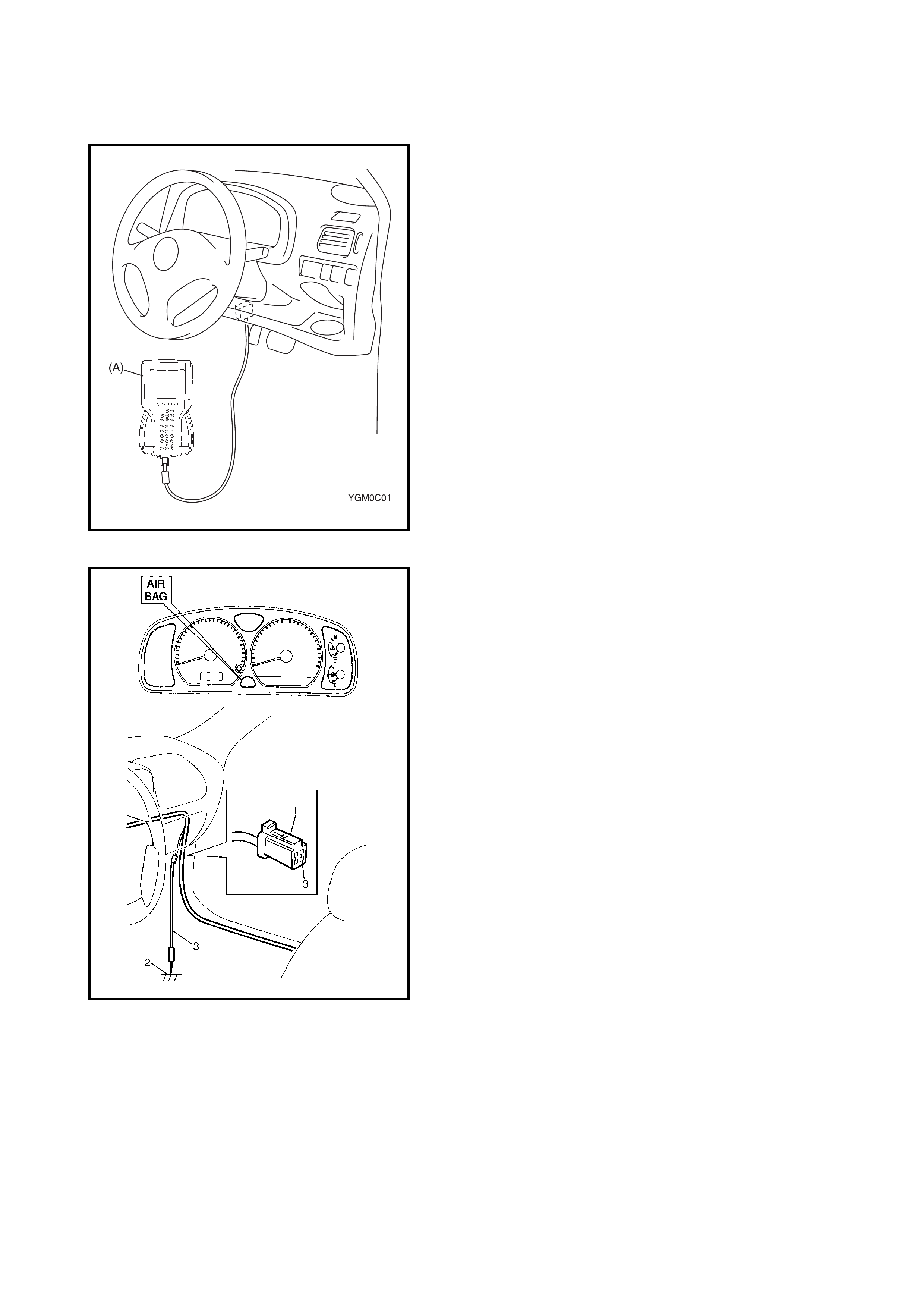
Using Tech 2
1. Turn ignition switch to OFF position.
2. Connect Tech 2 to the data link connector (DLC) (1)
located on underside of instrument panel at driver’s
seat side.
3. Turn ignition switch to ON position.
4. Read DT C accor ding to instr uctions displa ye d on Tech
2 and print it or write it down. Refer to Tech 2
operator’s manual for further details.
If communication between Tech 2 and SDM is not
possible, refer 2.13 TABLE E - SDM CANNOT
COMMUNICATE THROUGH THE SERIAL DATA
CIRCUIT in this Section.
5. After compl eting the check, turn ignit ion switch to OFF
position and disconnect Tech 2 from data link
connector (DLC).
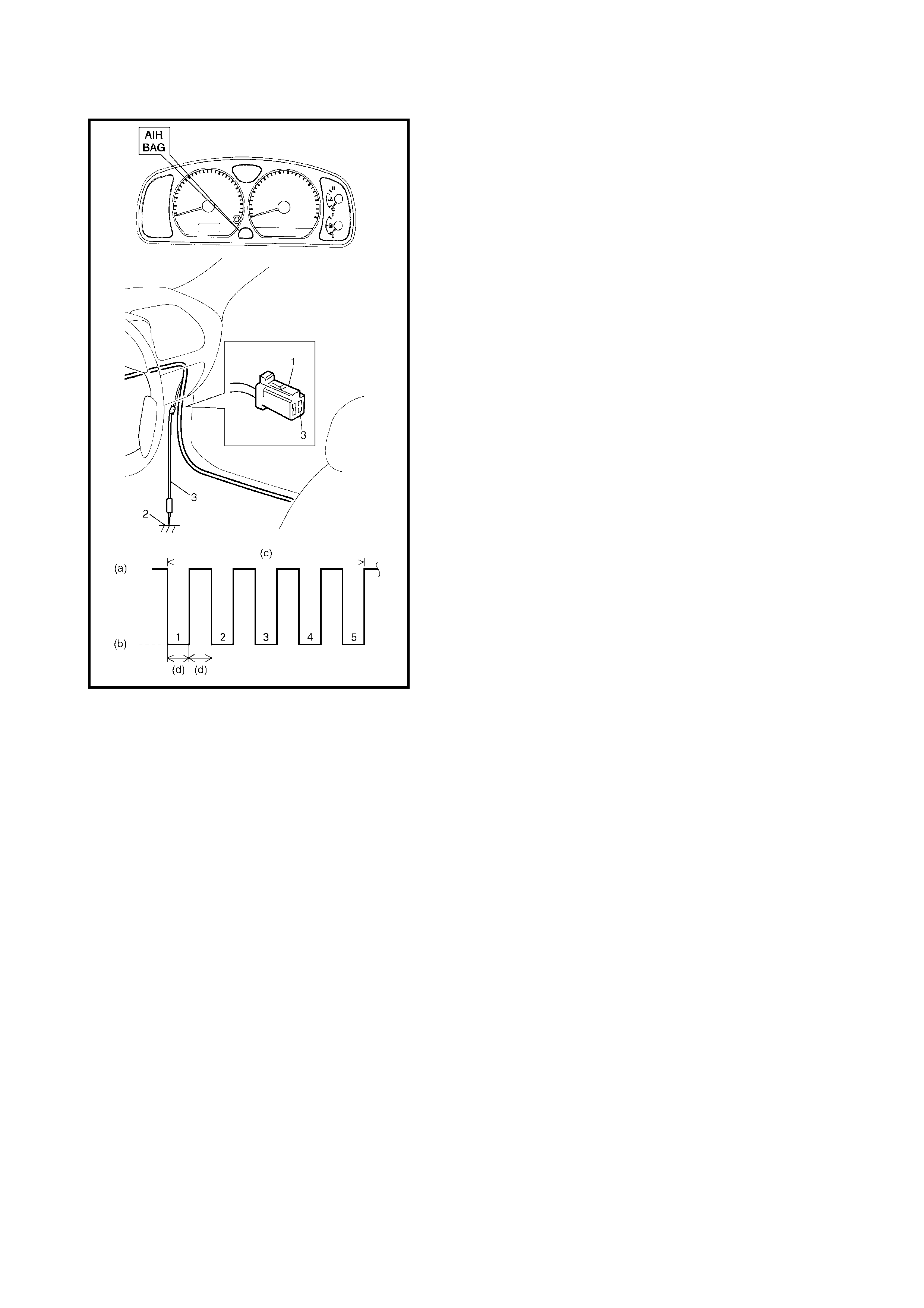
Not Using Tech 2
1. Check that the malfunction indicator lamp (airbag
warning lamp) comes ON when ignition switch is
turned to ON position.
If it does not come ON, proceed to 2.10 TABLE B -
AIRBAG WARNING LAMP DOES NOT COME ON.
2. Using service wire (4), connect diagnosis switch
terminal (3 ) in diagnos is connecto r No. 3 (1) to gr ound
(2).
3. Read DTC from flashing pattern of malfunction
indicator lamp (airbag warning lamp), refer to 2.8 DTC
TABLE in this Section.
If lamp does not ind icate DT C, procee d to 2 .12 TABL E
D - AIRBAG WARNING LAMP CANNOT
INDICATEFLASHING.
4. After compl eting the check, turn ignit ion switch to OFF
position and disconnect the service wire from airbag
diagnosis connector No. 3.
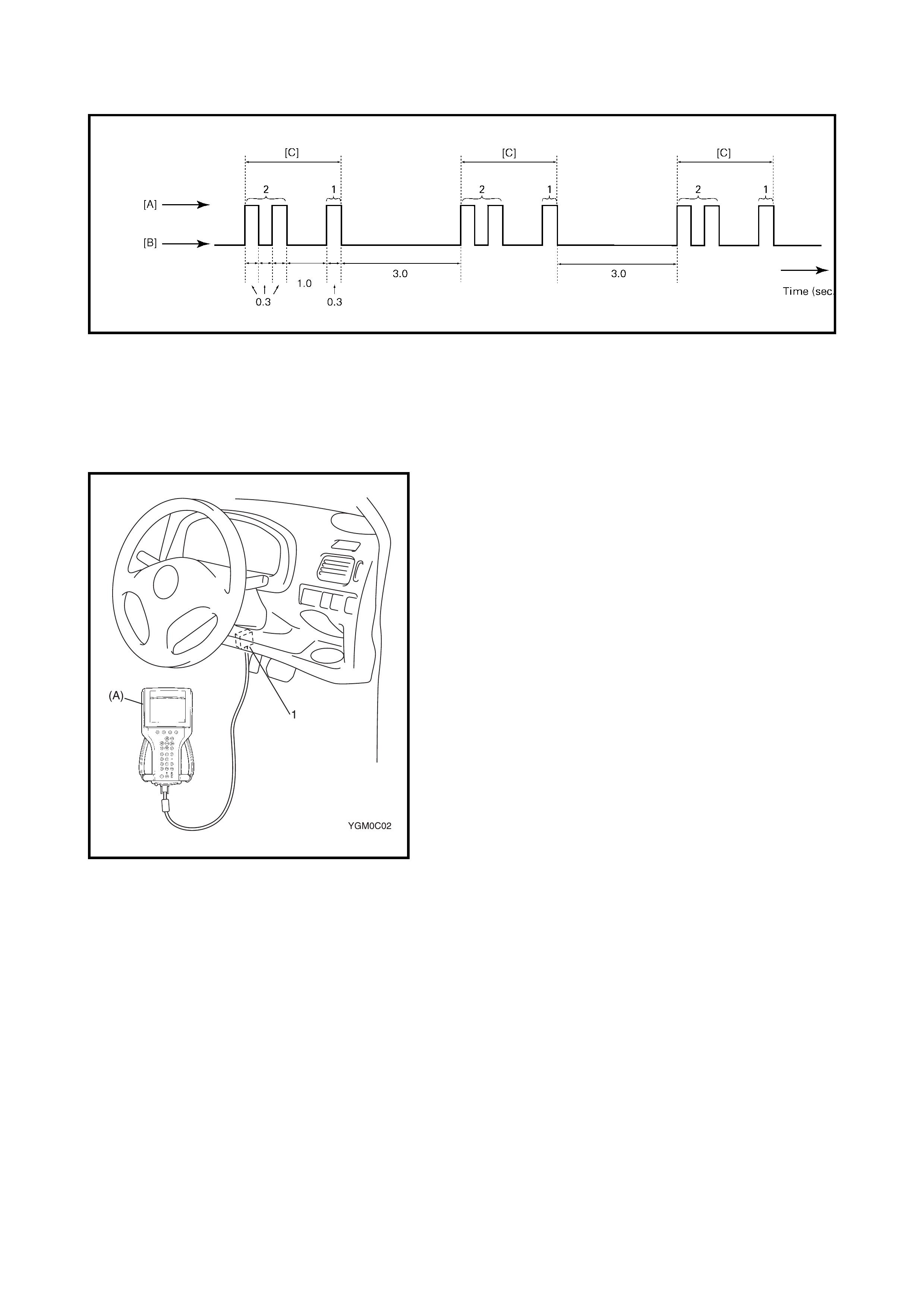
EXAMPLE: When driver airbag initiator circuit resistance high (DTC B1021) is set
Legend
2.7 DTC CLEARANCE
Using Tech 2
1. Turn ignition switch to OFF position.
2. Connect Tech 2 (A) to the data link connector (DLC) (1)
in the same manner as when making this connection
for DTC check.
3. Turn ignition switch to ON position.
4. Erase DTC according to instructions displayed on Tech
2. Refer to Tech 2 operator’s manual for further details.
5. After compl eting the check, turn ignit ion switch to OFF
position and disconnect Tech 2 from DLC.
6. Perform DTC CHECK and confirm that normal DTC
(NO CODES) is displayed and not malfunction DTC.
NOTE:
If DTC B1051 or DTC B1071 is stored in SDM, it
is not possible to clear DTC.
[A]: Airbag warning lamp is turned ON [C]: Code No.21
[B]: Airbag warning lamp is turned OFF
Not Using Tech 2
1. Turn ignition switch to ON position and wait about 6
seconds or more.
2. Using service wire (4), repeat shorting and opening
between diagnosis switch terminal (3) on the airbag
diagnosi s c onn ec tor No. 3 ( 1) and body grou nd ( 2) five
times at about 1 second intervals.
3. Perform DTC CHECK and confirm that normal DTC
(DTC 12) is displayed and not malfunction DTC.
NOTE:
If DTC B1051 or DTC B1071 is stored in SDM, it
is not possible to clear DTC.
Legend
(a) Open
(b) Short
(c) About 10 seconds
(d) 1 sec.

2.8 DTC TABLE
NOTE:
• When 2 or more codes are indicated, the lowest numbered code will appear first.
• Current DTC and history DTC can be identified by lighting and flashing of airbag warning lamp as
follows. However, if a multiple number of DTC’s are set if even one of them is a current DTC, airbag
warning lamp rema ins on after ignition s witch is turn ed ON. Therefo re, it is not pos sible to ident ify any of
them as to whether it is a current one or a history one. The use of Tech 2 will make identification possible.)
DTC airbag warning lamp
flashing pattern Diagnosis
NO. MODE
–12 Normal –
B1015 15 Passenger
airbag circuit Resistance high Diagnose trouble
according to
diagnostic flow
table
corresponding to
each code No.
B1016 16 Resistance low
B1018 18 Short to ground
B1019 19 Short to power circuit
B1021 21 Driver airbag
circuit Resistance high
B1022 22 Resistance low
B1024 24 Short to ground
B1025 25 Short to power circuit
B1031 31 Power source
voltage Too high
B1032 32 Too low
B1041 41 Driver
pretensioner
circuit
Resistance high
B1042 42 Resistance low
B1043 43 Short to ground
B1044 44 Short to power circuit
B1045 45 Passenger
pretensioner
circuit
Resistance high
B1046 46 Resistance low
B1047 47 Short to ground
B1048 48 Short to power circuit
B1051 51 SDM Frontal crash detected
B1061 61 Airbag
warning lamp
circuit
Circuit Fail ur e
B1071 71 SDM Internal fault
2.9 TABLE A - AIRBAG WARNING LAMP COMES ON STEADY WITHOUT FLASHING
Please refer to 2.12 TABLE D - AIRBAG WARNING LAMP CANNOT INDICATE FLASHING for Table
information.
2.10 TABLE B - AIRBAG WARNING LAMP DOES NOT COME ON
Please refer to 2.12 TABLE D - AIRBAG WARNING LAMP CANNOT INDICATE FLASHING for Table
information.
2.11 TABLE C - AIRBAG WARNING LAMP FLASHES
Please refer to 2.12 TABLE D - AIRBAG WARNING LAMP CANNOT INDICATE FLASHING for Table
information.
2.12 TABLE D - AIRBAG WARNING LAMP CANNOT IN DICATE FLASHING
WIRING DIAGRAM
Legend
Current DTC is set.
(Abnormality exists at present.) History DTC is set only.
(Faulty condit ion occurr ed onc e in
the past but normal condition is
restored at present.)
Airbag warning lamp after ignition
switch ON Flashing 6 times and turns on. Flashing 6 times and turns off.
Airbag warning lamp when
grounding diagnosis switch Current DTC is displayed. History DTC is displayed.
1. From main fuse 7. SDM
2. Ignition switch 8. To DLC
3. METER fuse 9. To ECM, TCM & ABS control module (if equipped)
4. Airbag warning lamp in combination meter 10. Airbag diagnosis connector No. 3
5. Airbag fuse 11. Ground for airbag system
6. Connection detection pin [A]: Airbag harness in floor harness

CAUTION:
•Perform 2.4 AIRBAG DIAGNOSTIC SYSTEM CHECK before starting diagnosis according to flow
table.
• When measurement of resistance or voltage is required in this table, use a specified digital
multimeter along with a correct terminal adapter from the connector test adapter kit, refer
5. SPECIAL TOOLS in this Section.
• When a check for proper connection is required, refer to 2.3 INTERMITTENTS AND POOR
CONNECTIONS in this Section.
• If there is an open circuit in the airbag wire harness, connector or a terminal is found damaged,
replace the wire harness, connector and terminal as an assembly.
TABLE TEST DESCRIPTION
Table A:
STEP 1: Check airbag fuse.
STEP 2: Check power source circuit.
STEP 3: Check airbag warning lamp circuit.
Table B:
STEP 1: Check combination meter power feed circuit.
STEP 2: Check electrical connection check mechanism in SDM connector.
STEP 3: Check airbag warning lamp circuit.
STEP 4: Check airbag bulb and combination meter.
STEP 5: Check open in airbag warning lamp circuit.
STEP 6: Check short from airbag warning lamp circuit to power circuit.
Table C and D:
STEP 1: Check airbag diagnosis connector No. 3.
STEP 2: Check diagnosis switch circuit for airbag system.
DIAGNOSTIC FLOW TABLE
Table A: Airbag Warning Lamp Comes ON Steady Without Flashing
Fig. for STEP 2
Step Action Yes No
1 1. Ignition switch OFF.
2. Remov e and ins pe ct airba g fuse .
Is fuse good?
Go to step 2. RED wire short to
ground. After repair,
replace airbag fuse.
2 1. Disconnect SDM connector.
2. Check proper connection to SDM at terminal
L51-4.
3. If OK then check voltage between L51-4
termin al o f SDM conne ct or and b ody grou nd
with ignition switch ON.
Is it 8 V or more?
Go to step 3. RED wire (between
airbag fuse and SDM
connect or ) ope n BLK/
YEL wire (between
ignition switch and
airbag fuse) open or
short to ground
3 1. Disconnect 16-pin connector from
combination meter. Refer to
2.10 COMBINATION METER in Section 8.
2. Chec k resi stance betwee n L51-2 t erminal of
SDM connector and body ground.
Is resi sta nc e 1M Ω or more?
Substitute a
known-good SDM
and rechec k.
YEL/BLK wire (between
combination meter and
SDM connector) short to
ground

Fig. for STEP 3 (A): Special Tool 0993 2- 760 10
NOTE: Upon completion of inspection and repair work,
perform following:
•Reconnect all airbag system components and ensure all
components are properly mounted.
•Repeat airbag 2.4 AIRBAG DIAGNOSTIC SYSTEM
CHECK to confirm that the trouble has been corrected.
Table B: Airbag Warning Lamp Does Not Come
ON
Step Action Yes No
1 1. Set parking brake.
2. Note combination meter when ignition switch
is turned ON.
3. Does the BRAKE indicator (warning lamp)
come ON?
Go to step 2. BLK/YEL, BLU wire or
METER fuse open or
short to ground
2 1. Disconnect SDM connector.
2. Check electrical connection check
mechanism. (Connection pin and L1 and L2
terminals for dents, cracks or damages.)
Is it in good condition?
Go to step 3. Repair electrical
connection check
mechanism.
3 1. Check proper connection to SDM at terminal
L51-2.
2. If OK then check voltage from L51-2 terminal
of SDM connector to body ground with
ignition switch ON.
Is it 8 V or more?
Substitute a
known-good SDM
and rechec k.
Go to step 4.
4 1. Turn ignition switch OFF.
2. Remove and inspect the AIRBAG warning
lamp bulb and combination meter. Refer to
2.10 COMBINATION METER in Section 8.
Are they in good condition?
Go to step 5. Replace AIRBAG
warning lamp bulb or
combination meter.
5 1. Ch eck pro per conn ectio n to the c ombin ation
meter at YEL/BLK terminal for the AIRBAG
warning lamp and to the SDM at terminal
L51-2.
2. If OK, check the resistance between YEL/
BLK wire terminal of the combination meter
connection (16-pin connector) and L51-2
terminal of the SDM connector.
Is resi sta n c e 1Ω or le ss?
Go to step 6. Repair high resistance or
open in YEL/BLK wire
circuit, between
combination meter and
SDM.
6 1. Measure voltage from L51-2 terminal of
SDM connector to body ground with ignition
switch ON .
Is it 10 V or more?
Repair short from
YEL/ BLK wire circuit
(between
combination meter
and SDM) to power
circuit.
Substitute a known-good
SDM and recheck.
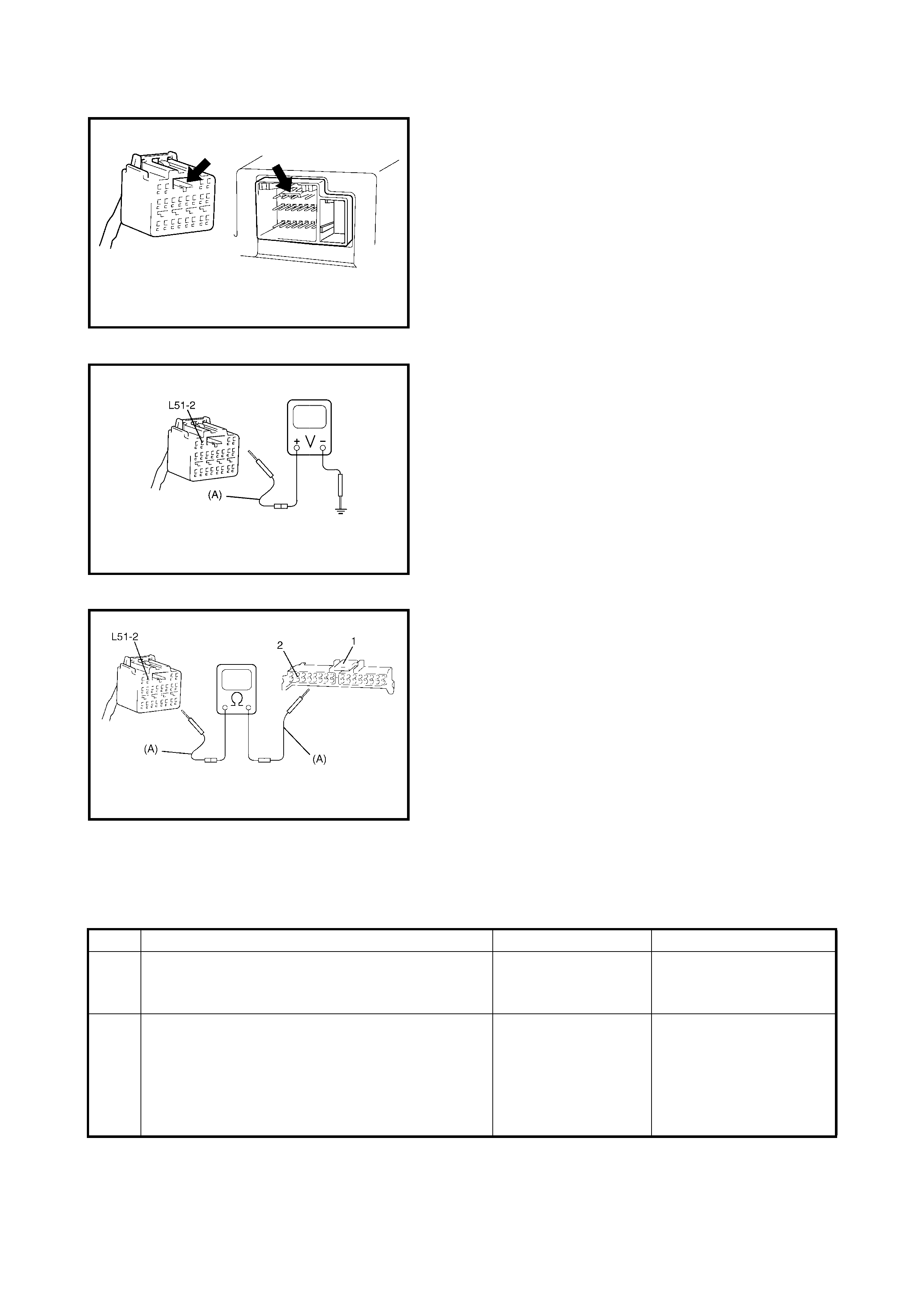
Fig. for STEP 2
Fig. for STEP 3 and 5 (A): Special tool 09932-76010
Fig. for STEP 4 (A): Special tool 09932-76010
Legend.
NOTE: Upon completion of inspection and repair work, perform following:
• Reconnect all airbag system components, ensure all components are properly mounted.
• Repeat 2.4 AIRBAG DIAGNOSTIC SYSTEM CHECK to confirm that the trouble has been corrected.
Table C: Airbag Warning Lamp Flashes
1. 16-p in co nnec to r (for co mbi nati on meter)
2. YEL/BLK wire terminal
Step Action Yes No
1 1. Check airbag diagnosis connector No. 3.
Is a service wire connected to the diagnosis
switch term in al and groun d term ina l?
Remove service wire. Go to step 2.
2 1. With ignition switch OFF, disconnect
SDM.connector.
2. Measure resistance between L51-15
terminal of SDM connector and body
ground.
Is resi sta nc e 1M Ω or more?
Substitute a known-
good SDM and
recheck.
Repair short from PPL
wire circuit to ground.
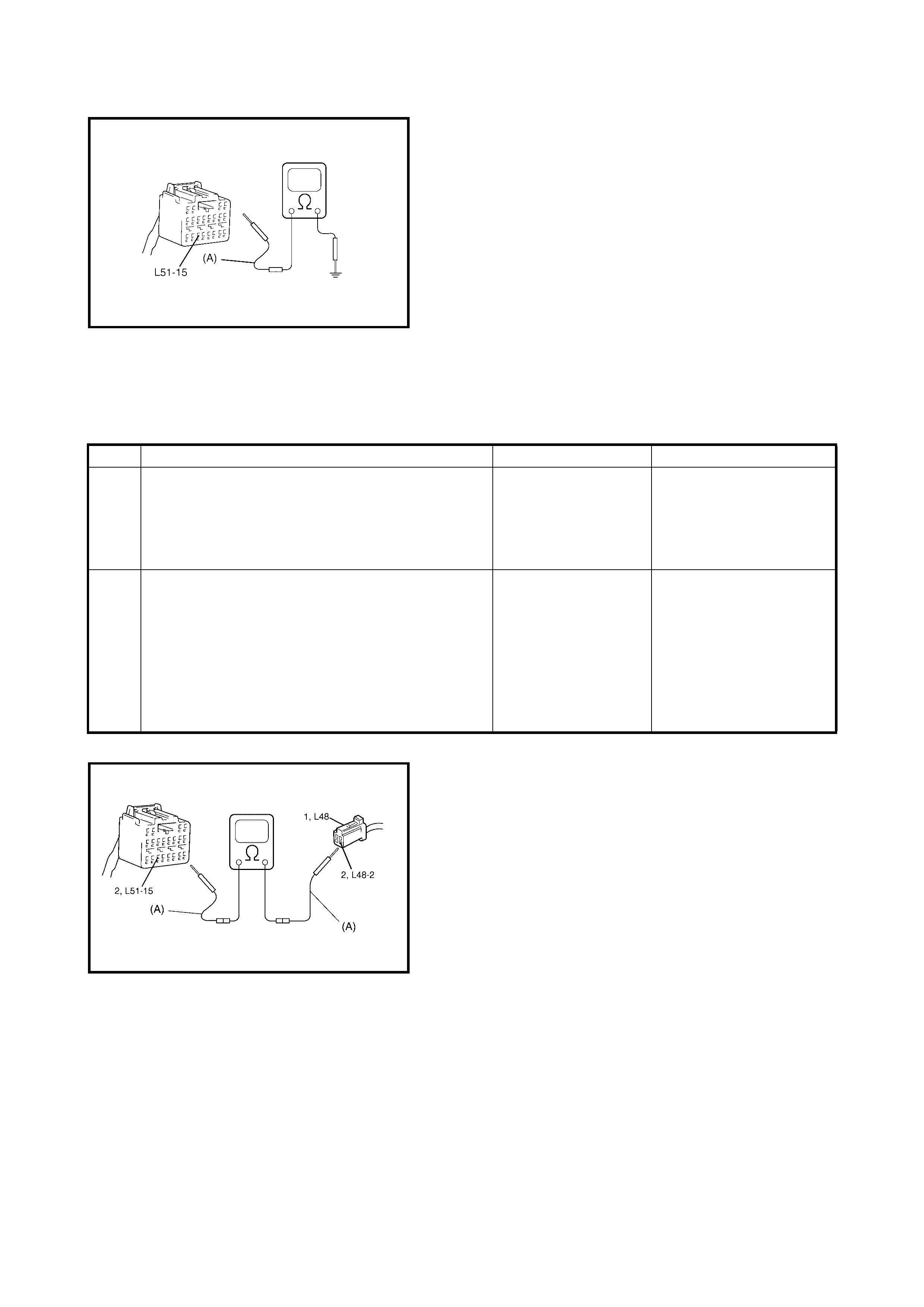
Fig. for STEP 2 (A): Special tool 09932-76010
NOTE: Upon completion of inspection and repair work, perform following:
• Reconnect all airbag system components and ensure all components are properly mounted.
• Repeat 2.4 AIRBAG DIAGNOSTIC SYSTEM CHECK to confirm that the trouble has been corrected.
Table D: Airbag Warning Lamp Cannot Indicate DTC by Flashing
Fig. for STEP 2 (A): Special tool 09932-76010
Legend
NOTE: Upon completion of inspection and repair work, perform following items.
• Reconnect all airbag system components and ensure all components are properly mounted.
• Repeat 2.4 AIRBAG DIAGNOSTIC SYSTEM CHECK to confirm that the trouble has been corrected.
Step Action Yes No
1 1. Inspect service wire connection between
diagnostic switch terminal on airbag
diagnosis connector No. 3 and body ground.
Is it securely connected?
Go to step 2. Properly connect service
wire to diagnostic switch
terminal on airbag
diagnosis connector No.
3 and body ground.
2 1. Disconnect SDM connector from SDM.
2. Check for proper connection at PPL wire
(L51-15 terminal of SDM connector and
L48-2 terminal of airbag diagnosis connector
No. 3) terminals.
3. If OK then measure resistance between
L51-15 terminal and L48-2 terminal.
Is resi sta nc e 1 Ω or more?
Substitute a known
good SDM and
recheck
Check PPL wire
terminals. If OK then PPL
wire circuit high
resistance or open.
1. Airbag diagnosis connector No. 3.
2. PPL wire terminal
2.13 TABLE E - SDM CANN OT COMMUNICATE THROUGH THE S ERIAL DATA
CIRCUIT
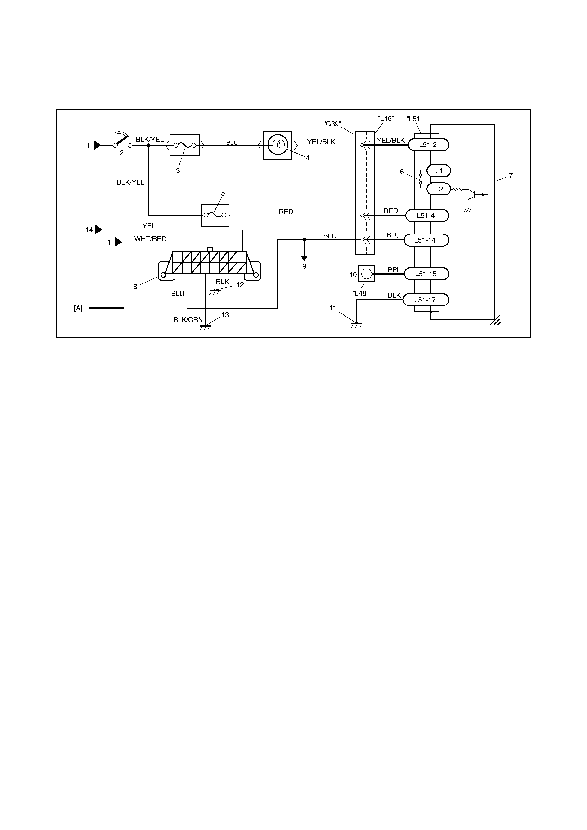
WIRING DIAGRAM
Legend
CAUTION:
•Perform 2.4 AIRBAG DIAGNOSTIC SYSTEM CHECK before starting diagnosis according to flow
table.
• When measur ement of resistance or voltage is required in this table, use a specified digital multi-
meter along with a correct terminal adapter from the connector test adapter kit, refer
5. SPECIAL TOOLS in this Section.
• When a check for proper connection is required, refer to 2.3 INTERMITTENTS AND POOR
CONNECTIONS in this Section.
• If there is ope n circuit in the airba g wire h arness, c onnect or or te rmin al is found dama ged, repla ce
the wire harness, connector and terminal as an assembly.
TABLE TEST DESCRIPTION
STEP 1: An improper connection to the data link connector (DLC) will prevent communications from being
established.
STEP 2: This test checks whether it is possible to communicate with other control module.
STEP 3: This test checks for an open in BLU circuit (in airbag harness).
[A]: Airbag harness in floor harness 8. DLC
1. From main fuse 9. To ECM, TCM and ABS control module (if equipped)
2. Ignition switch 10. Airbag diagnosis connector No. 3.
3. METER fuse 11. Ground for airbag system
4. Airbag warning lamp in combination lamp 12. Ground on body
5. Airbag fuse 13. Ground on Engine block
6. Connection detection pin 14. Immobiliser control module
7. SDM
DIAGNOSTIC FLOW TABLE
Fig. for STEP 1 Legend
Fig. for STEP 3 (A): Special tool 09932-76010
Legend
NOTE: Upon completion of inspection and repair work, perform following:
• Reconnect all airbag system components and ensure all components are properly mounted.
• Repeat 2.4 AIRBAG DIAGNOSTIC SYSTEM CHECK to confirm that the trouble has been corrected.
Step Action Yes No
1 1. Ensure that Tech 2 functions correctly.
2. Ignition switch OFF.
3. Check proper connection of Tech 2 to DLC.
Is conne ction in good cond iti on?
Go to step 2. Properly connect Tech 2
to DLC.
2 1. Check if commu nicat ion i s possib le b y tr ying
communication with another control module
(ECM, TCM or ABS control module (if
equipped)).
Is it possible to communicate with other control
module?
Go to step 3. Repair open in common
section of serial data
circuit (BLU wire circuit)
used by all controllers or
short to ground or power
circuit which has
occurred some-where in
serial data circuit (BLU
wire circuit).
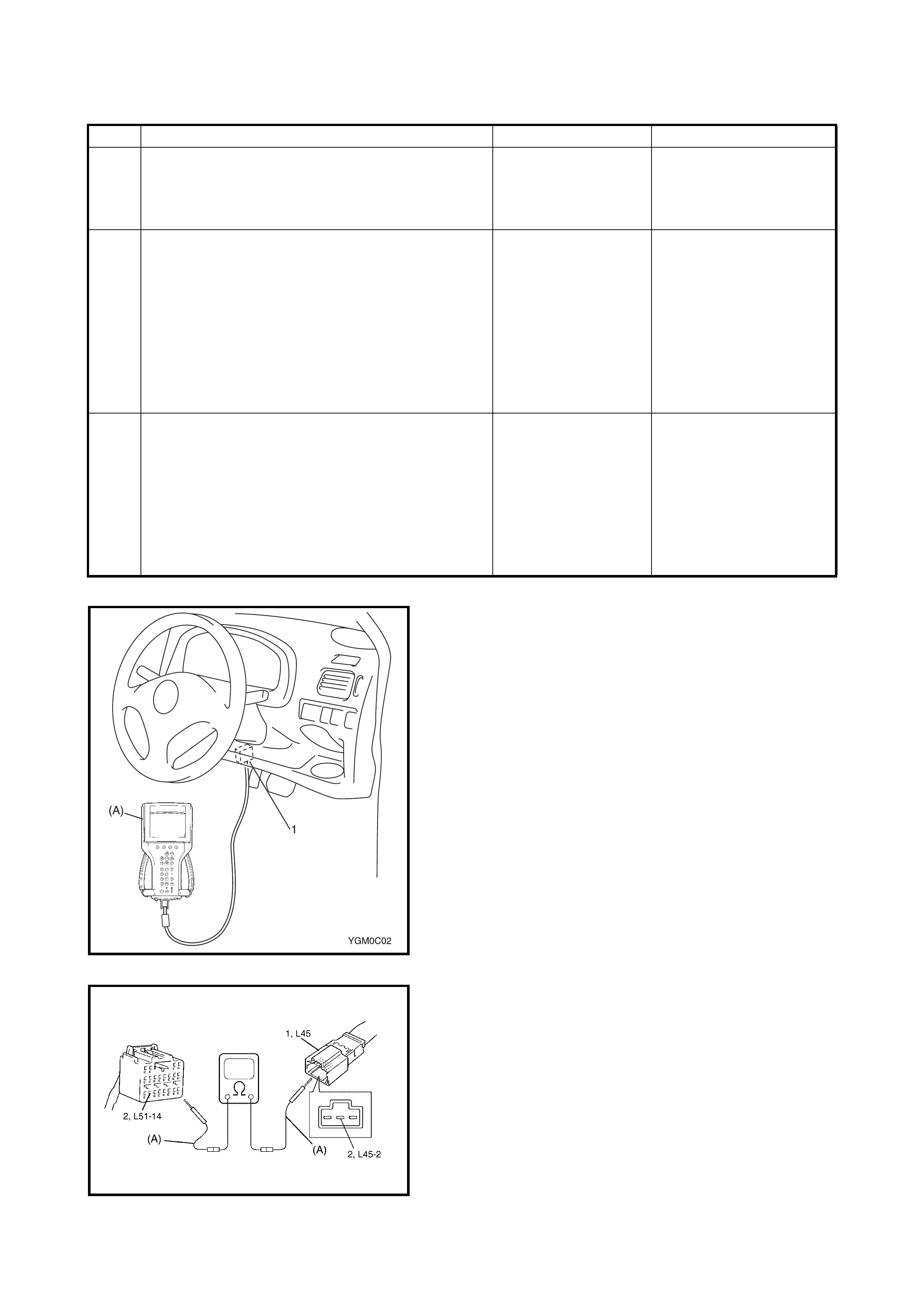
3 1. With ignition switch OFF, disconnect SDM
connector and L45 connector.
2. Check proper connection at L45-2 (BLU
wire) terminal for DLC.
3. If OK, then check resistance between L45-2
(BLU wire) terminal and L51-14 (BLU wire)
terminal of SDM connector.
Is resi sta nc e 1 Ω or less?
Substitute a known-
good SDM and
recheck.
Repair high resistance or
open in BLU wire circuit
(in airbag har nes s).
1. DLC
(A). Scan tool
1. Airbag harness (in floor harness) side connector
2. BLU wire terminal
2.14 DTC B1015 - PASSENGER AIRBAG INITIATOR CIRCUIT RESISTANCE HIGH
Please refer to 2.17 DTC B1019 - PASSENGER AIRBAG INITIATOR CIRCUIT SHORT TO POWER CIRCUIT
for DTC information.
2.15 DTC B1 016 - PASSENGER AIRBAG INITIATOR CIRCUIT RESISTANCE LOW
Please refer to 2.17 DTC B1019 - PASSENGER AIRBAG INITIATOR CIRCUIT SHORT TO POWER CIRCUIT
for DTC information.
2.16 DTC B1018 - PASSENGER AIRBAG INITIATOR CIRCUIT SHORT TO GROUND
Please refer to 2.17 DTC B1019 - PASSENGER AIRBAG INITIATOR CIRCUIT SHORT TO POWER CIRCUIT
for DTC information.
2.17 DTC B101 9 - PAS SENGER AIRBAG INITIATOR CIRCUIT SHORT TO POWER
CIRCUIT
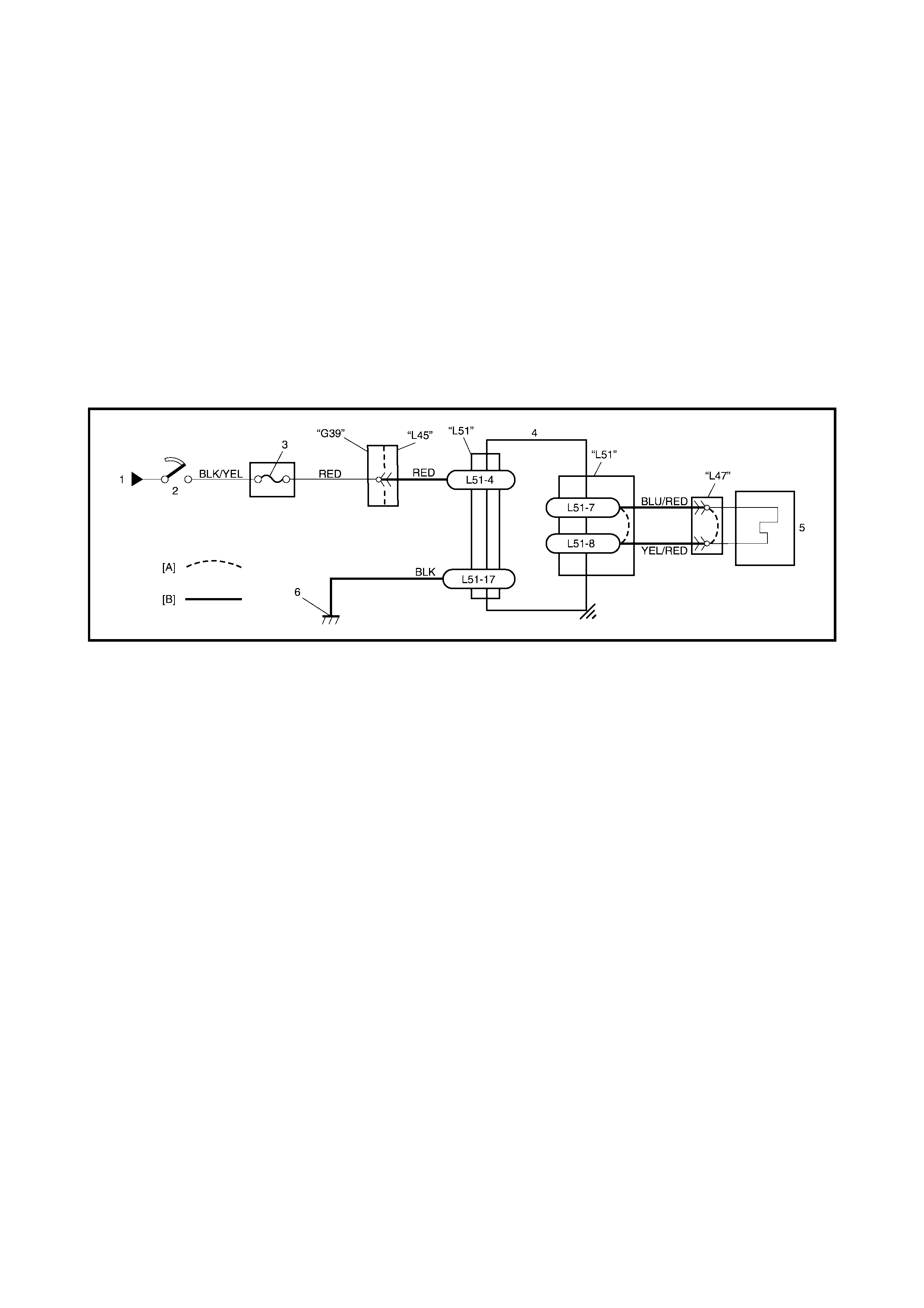
WIRING DIAGRAM
Legend
CAUTION:
•Perform 2.4 AIRBAG DIAGNOSTIC SYSTEM CHECK before starting diagnosis according to flow
table.
• When measur ement of resistance or voltage is required in this table, use a specified digital multi-
meter along with a correct terminal adapter from the connector test adapter kit, refer
5. SPECIAL TOOLS in this Section.
• When a check for proper connection is required, refer to 2.3 INTERMITTENTS AND POOR
CONNECTIONS in this Section.
• If there is ope n circuit in the airba g wire h arness, c onnect or or te rmin al is found dama ged, repla ce
the wire harness, connector and terminal as an assembly.
DTC WILL SET WHEN
DTC B1015:
The combined resistance of the passenger airbag (inflator) module, harness wiring and connector terminal
contact is above a specified value for specified time.
DTC B1016:
The combined resistance of the passenger airbag (inflator) module, harness wiring and connector terminal
contact is below a specified value for specified time.
DTC B1018:
The voltage measured at passenger airbag initiator circuit is below a specified value for specified time.
DTC B1019:
The voltage measured at passenger airbag initiator circuit is above a specified value for specified time.
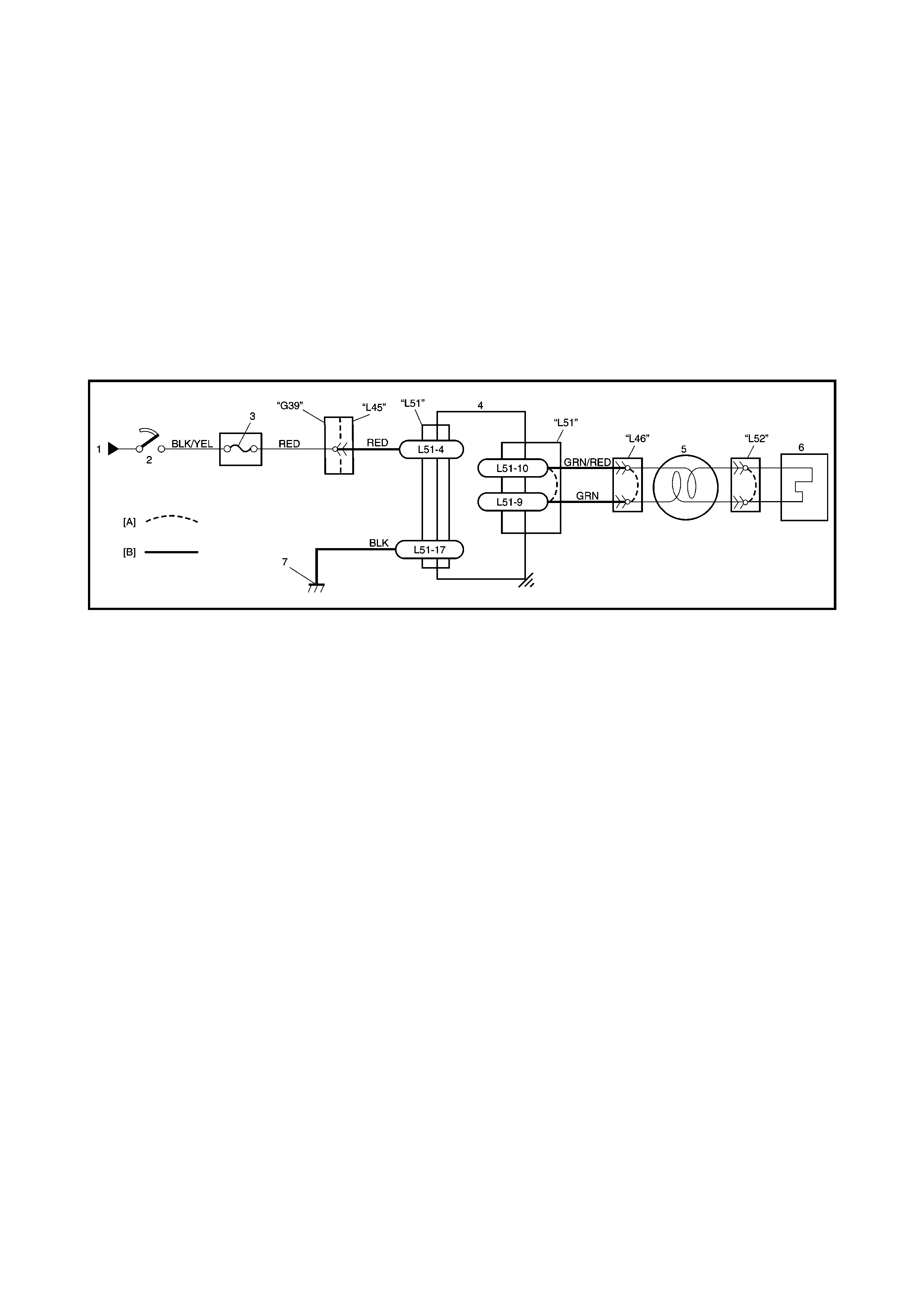
[A]: Shorting bar 1. From main fuse 3. AIRBAG fuse 5. Passenger airbag (inflator) mod-
ule
[B]: Airbag harness 2. Ignition switch 4. SDM 6. Ground for airbag system
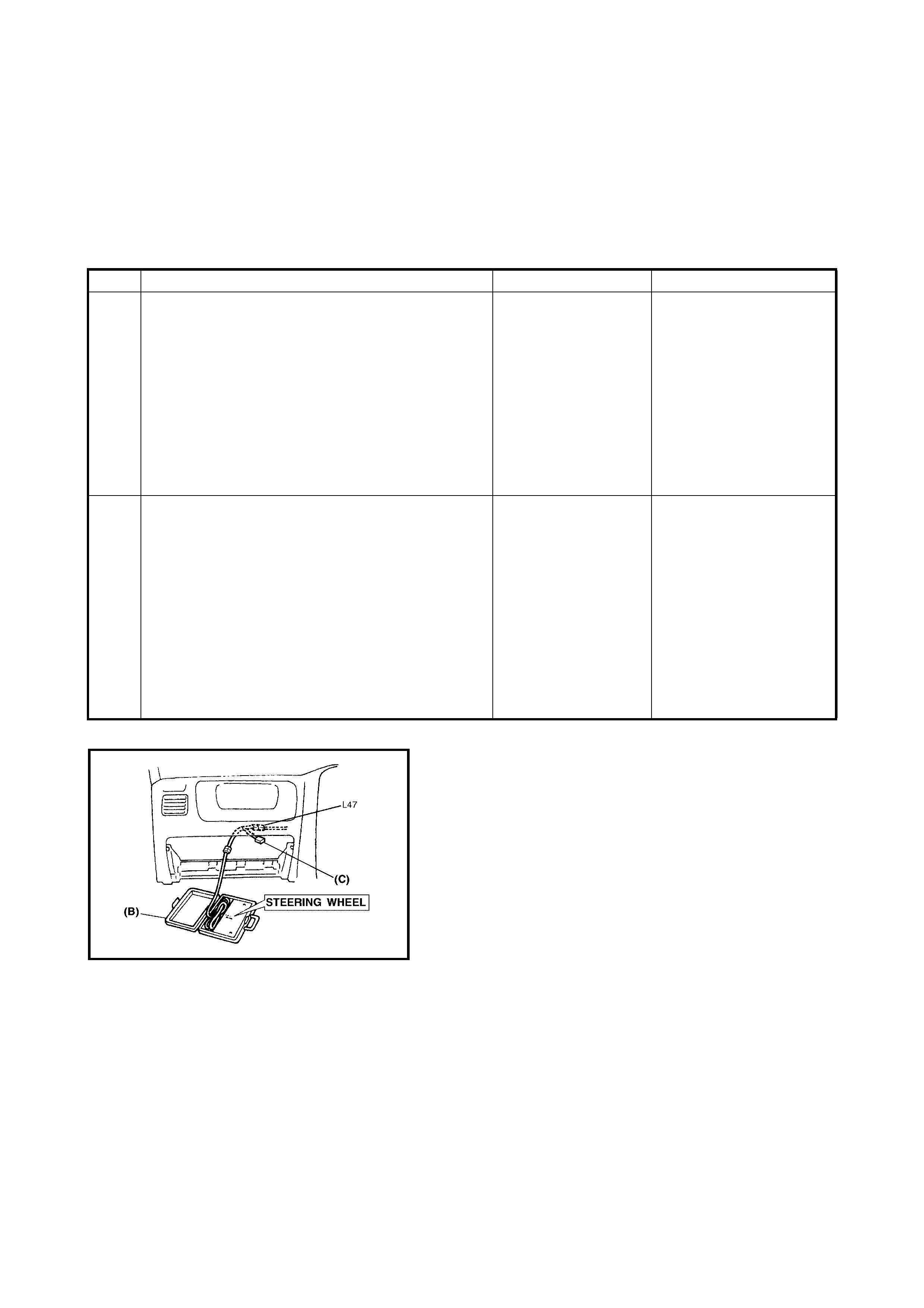
TABLE TEST DESCRIPTION
DTC B1015, B1016, B1018 and B1019:
STEP 1: Check whether malfunction is in passenger airbag (inflator) module.
STEP 2: Check passenger airbag (inflator) module initiator circuit in airbag harness.
STEP 3: Check passenger airbag (inflator) module initiator circuit in airbag harness. (for DTC B1018 and
B1019 only)
DIAGNOSTIC FLOW TABLE
DTC B1015: Passenger Airbag Initiator Circuit Resistance High
Fig. for STEP 1 and 2
Step Action Yes No
1 1. With ignition switch OFF, disconnect
passenger airbag (inflator) module
connector behind the glove box.
2. Check proper connection to passenger
airbag (inflator) module at terminals in L47
connector.
3. If OK then connect S pecial Tools (B) and (C)
to passenger airbag (inflator) module
connector disconnected at the step 1).
With ignition switch ON, is DTC B1015 current?
Go to step 2. Ignition switch OFF.
Replace passenger
airbag (inflato r) modul e,
refe r to 3.4 PASSE NGER
AIRBAG (INFLATOR)
MODULE in th is Sect ion) .
2 1. With ignition switch OFF, disconnect SDM
connector.
2. Check proper connection to SDM at
terminals L51-7 and L51-8.
3. If OK, release shorting bar in SDM
connector by inserting release tool
incorporated in special tool (A).
4. Measure resistance between L51-7 and
L51-8 terminals with special tools (B) and
(C) connected to L47 connector.
Is resi stan c e 4.5 Ω or less?
Substitute a
known-good SDM
and rechec k.
Repair high resistance or
open in YEL/RED or
BLU/RED wire circuit.
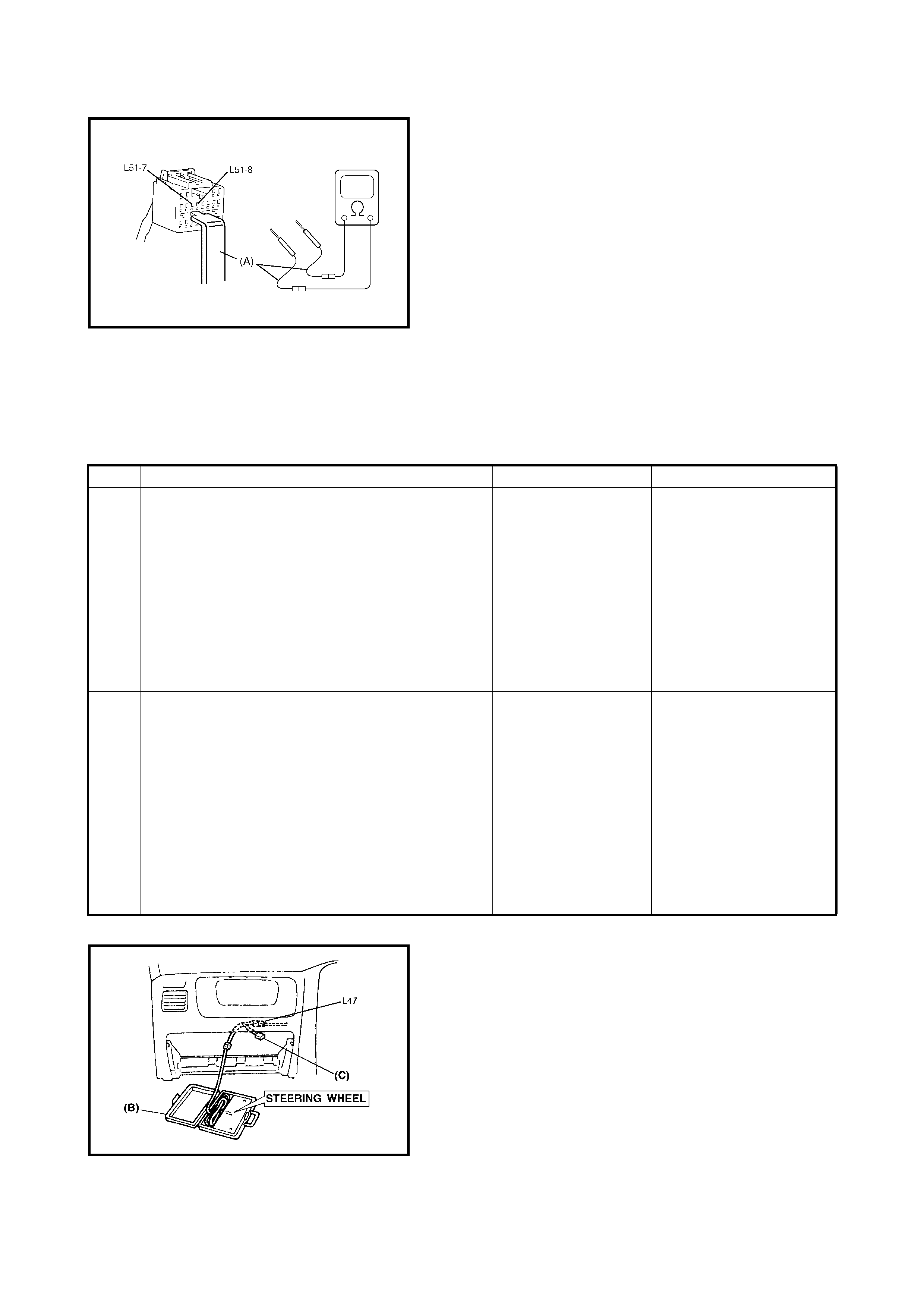
Fig. for STEP 2 Special tool:
(A) 09932-76010
(B) 09932-75010
(C) 09932-78340
NOTE: Upon completion of inspection and repair work, perform following:
• Reconnect all airbag system components and ensure all components are properly mounted.
• Clear diagnostic trouble codes, refer to 2.7 DTC CLEARANCE in this Section, if any.
• Repeat 2.4 AIRBAG DIAGNOSTIC SYSTEM CHECK to confirm that the trouble has been corrected.
DTC B1016: Passenger Airbag Initiator Circuit Resistance Low
Fig. for STEP 1 and 2
Step Action Yes No
1 1. With ignition switch OFF, disconnect
passenger airbag (inflator) module
connector behind the glove box.
2. Check proper connection to passenger
airbag (inflator) module at terminals in L47
connector.
3. If OK then connect special tools (B) and (C)
to passenger airbag (inflator) module
connector, disconnected at the step 1).
With ignition switch ON, is DTC B1016 current?
Go to step 2. Ignition switch OFF.
Replace passenger
airbag (inflato r) modul e,
refe r to 3.4 PASSE NGER
AIRBAG (INFLATOR)
MODULE in this Section.
2 1. With ignition switch OFF, disconnect SDM
connector.
2. Check proper connection to SDM at
terminals L51-7 and L51-8.
3. If OK, release shorting bar in SDM
connector by inserting release tool
incorporated in special tool (A).
4. Measure resistance between L51-7 and
L51-8 terminals with special tools (B) and
(C) connected to L47 connector.
Is resi stan c e 1.4 Ω or more?
Substitute a known-
good SDM and
recheck.
Repair short from YEL/
RED wire circuit to BLU/
RED wire circuit or from
YEL/RED or BLU/RED
wire circuit to other wire
circuit.
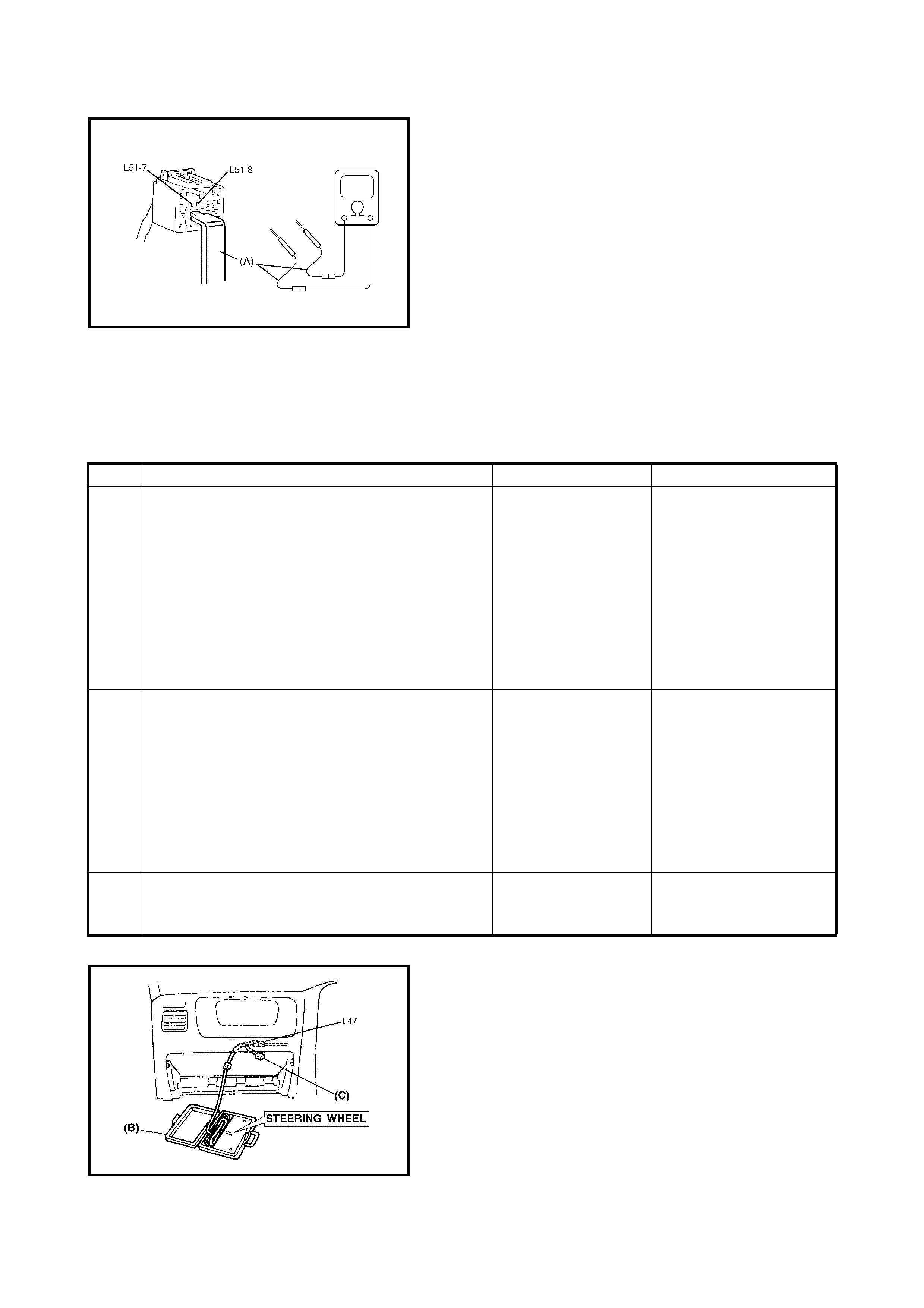
Fig. for STEP 2 Special tool:
(A) 09932-76010
(B) 09932-75010
(C) 09932-78340
NOTE: Upon completion of inspection and repair work, perform the following:
• Reconnect all airbag system components and ensure all components are properly mounted.
• Clear diagnostic trouble codes, refer to 2.7 DTC CLEARANCE in this Section, if any.
• Repeat 2.4 AIRBAG DIAGNOSTIC SYSTEM CHECK to confirm that the trouble has been corrected.
DTC B1018: Passenger Airbag Initiator Circuit Shorted to Ground
Fig. for STEP 1, 2 and 3
Step Action Yes No
1 1. With ignition switch OFF, disconnect
passenger airbag (inflator) module
connector behind the glove box.
2. Check proper connection to passenger
airbag (inflator) module at terminals in L47
connector.
3. If OK then connect S pecial Tools (B) and (C)
to passenger airbag (inflator) module
connector, disconnected at the step 1.
With ignition switch ON, is DTC B1018 current?
Go to step 2. Ignition switch OFF.
Replace passenger air-
bag (inflator) module,
refe r to 3.4 PASSE NGER
AIRBAG (INFLATOR)
MODULE in th is Sect ion) .
2 1. With ignition switch OFF, disconnect special
tools (B) and (C) from L47 connector and
SDM connector.
2. Release shorting bar in SDM connector by
inserting release tool incorporated in special
tool (A).
3. Measure resistance between L51-7
terminals and body ground.
Is resi sta nc e 1KΩ or more?
Go to step 3. Repair short from BLU/
RED wire circuit to
ground.
3 Measure resistance between L51-8 terminal and
body ground.
Is resi sta nc e 1M Ω or more?
Substitute a known-
good SDM and
recheck.
Repair short from YEL/
RED wire circuit to
ground.

Fig. for STEP 2 Special tool:
(A) 09932-76010
(B) 09932-75010
(C) 09932-78340
NOTE: Upon completion of inspection and repair work, perform the following:
• Reconnect all airbag system components and ensure all components are properly mounted.
• Clear diagnostic trouble codes, refer to 2.7 DTC CLEARANCE in this Section, if any.
• Repeat 2.4 AIRBAG DIAGNOSTIC SYSTEM CHECK to confirm that the trouble has been corrected.
DTC B1019: Passenger Airbag Initiator Circuit Short to Power Circuit
Step Action Yes No
1 1. With ignition switch OFF, disconnect
passenger airbag (inflator) module
connector behind the glove box.
2. Check proper connection to passenger
airbag (inflator) module at terminals in L47
connector.
3. If OK then connect special tools (B) and (C)
to passenger airbag (inflator) module
connector, disconnected at the step 1).
With ignition switch ON, is DTC B1019 current?
Go to step 2. Ignition switch OFF.
Replace passenger
airbag (inflato r) modul e,
refe r to 3.4 PASSE NGER
AIRBAG (INFLATOR)
MODULE in th is Sect ion) .
2 1. Wit h ignition switch OFF, disconnect special
tool (B) and (C) from L47 connector and
SDM connector.
2. Release shorting bar in SDM connector by
inser ting releas e tool incor porated i n special
tool (A).
3. Measure voltage from L51-7 terminal to
body ground.
With ignit i on switch ON, is voltage 1 V or less?
Go to step 3. Repair short from BLU/
RED wire circuit to power
circuit.
3 1. Measure voltage from L51-8 terminal to
body ground.
With ignit i on switch ON, is voltage 1 V or less?
Substitute a known-
good SDM and
recheck.
Repair short from YEL/
RED wire circuit to power
circuit.

Fig. for STEP 1, 2 and 3
Fig. for STEP 2 and 3 Special tool:
(A) 09932-76010
(B) 09932-75010
(C) 09932-78340
NOTE: Upon completion of inspection and repair work, perform the following:
• Reconnect all airbag system components and ensure all components are properly mounted.
• Clear diagnostic trouble codes, refer to 2.7 DTC CLEARANCE in this Section, if any.
• Repeat 2.4 AIRBAG DIAGNOSTIC SYSTEM CHECK in this Sectio n to c onfirm th at t he troubl e has been
corrected.
2.18 DTC B1021 – DR IVE R AIRBAG IN ITIATOR CIRCUIT RESISTANCE HIGH
Please refer to 2.21 DTC B1025 – DRIVER AIR BAG INITIATOR CIRCUIT SHORT TO POWER CIRCUIT for
DTC information.
2.19 DTC B1 022 – DRIVER AIRBAG INITIATOR CIRCUIT RESISTANCE LOW
Please refer to 2.21 DTC B1025 – DRIVER AIR BAG INITIATOR CIRCUIT SHORT TO POWER CIRCUIT for
DTC information.
2.20 DTC B1024 – DRIVER AIRBAG INITIATOR CIRCUIT SHORT TO GROUND
Please refer to 2.21 DTC B1025 – DRIVER AIR BAG INITIATOR CIRCUIT SHORT TO POWER CIRCUIT for
DTC information.
2.21 DTC B1025 – DRIVER AIRBAG INITIATOR CIRCUIT SHORT TO POWER CIRCUIT
WIRING DIAGRAM
Legend
CAUTION:
•Perform 2.4 AIRBAG DIAGNOSTIC SYSTEM CHECK before starting diagnosis according to flow
table.
• When measur ement of resistance or voltage is required in this table, use a specified digital multi-
meter along with a correct terminal adapter from the connector test adapter kit, refer
5. SPECIAL TOOLS in this Section.
• When a check for proper connection is required, refer to 2.3 INTERMITTENTS AND
POOR CONNECTIONS in this Section.
• If there is ope n circuit in the airba g wire h arness, c onnect or or te rmin al is found dama ged, repla ce
the wire harness, connector and terminal as an assembly.
DTC WILL SET WHEN
DTC B1021:
The combined resistance of the driver airbag (inflator) module, contact coil assembly, harness wiring and con-
nector terminal contact is above a specified value for specified time.
DTC B1022:
The combined resistance of the driver airbag (inflator) module, contact coil assembly, harness wiring and con-
nector terminal contact is below a specified value for specified time.
DTC B1024:
The voltage measured at driver airbag initiator circuit is below a specified value for specified time.
DTC B1025:
The voltage measured at driver airbag initiator circuit is above a specified value for specified time.
TABLE TEST DESCRIPTION
DTC B1021, B1022, B1024 and B1025:
STEP 1: Check whether malfunction is in contact coil and driver airbag (inflator) module or the others.
STEP 2: Check driver airbag (inflator) module initiator circuit in airbag harness.
STEP 3: Check whether malfunction is in contact coil or driver airbag (inflator) module.
[A]: Shorting bar 2. Ignition switch 5. Contact coil assembly
[B]: Airbag harness 3. Airbag fuse 6. Driver airbag (inflator) module
1. From main fuse 4. SDM 7. Ground for airbag system
DIAGNOSTIC FLOW TABLE
DTC B1021: Driver Airbag Initiator Circuit Resistance High
Fig. for STEP 1 and 2
Step Action Yes No
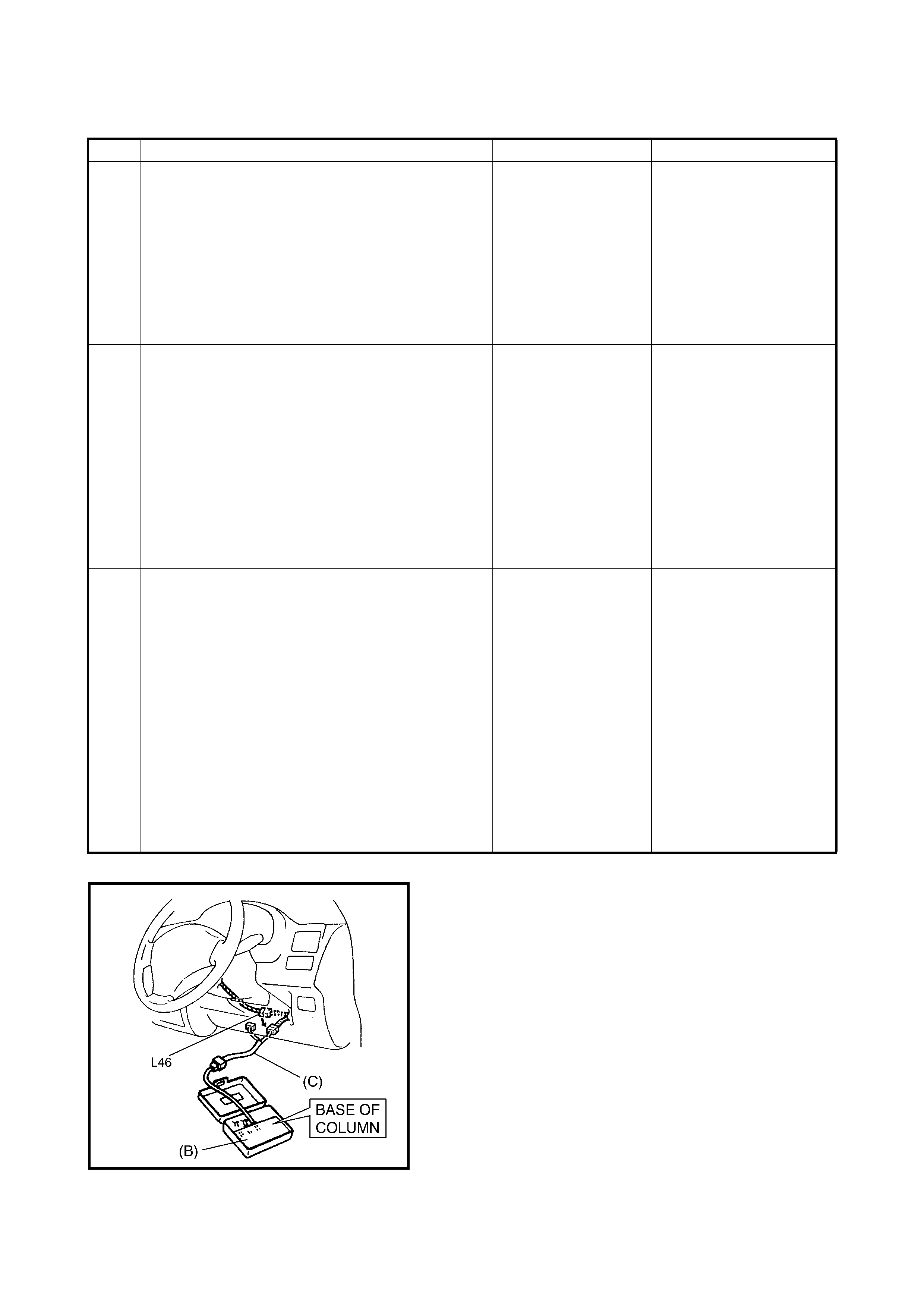
1 1. With ignition switch OFF, disconnect contact
coil connector located near the base of the
steering column.
2. Check proper connection to contact coil at
terminals in L46 connector.
3. If OK then connect special tools (B) and (C)
to contact coil connector, disconnected at
step 1).
With ignition switch ON, is DTC B1021 current?
Go to step 2. Go to step 3.
2 1. With ignition switch OFF, disconnect SDM
connector.
2. Check proper connection to SDM at
terminals L51-9 and L51-10.
3. If OK, release shorting bar in SDM
connector by inserting the release tool incor-
porated in special tool (A).
4. Measure resistance between L51-9 and
L51-10 terminals with connected special
tools (B) and (C) to L46 connector.
Is resi stan c e 4.5 Ω or less?
Substitute a known-
good SDM and
recheck.
Repair high resistance or
open in GRN or GRN/
RED wire circuit.
3 1. With ignition switch OFF, disconnect special
tools (B) and (C) from L46 connector then
reconnect contact coil connector located
near the base of the steering column.
2. Remove driver airbag (inflator) module from
steering wheel, refer to 3.2 DRIVER
AIRBAG (INFLATOR) MODULE in Section
3C).
3. Check proper connection to driver airbag
(inflator) module at terminals in L52
connector.
4. If OK then connect special tools (B) and (C)
to L52 connector.
With ignition switch ON, is DTC B1021 current?
Ignition switch OFF.
Replace contact coil
asse mbly, refer to
3.5 CONTACT COIL
AND COMBINATION
SWITCH ASSEM-
BLY in Section 3C.
Ignition switc h OFF.
Replace driv er airbag
(inflator) module, refer to
3.2 DRIVER AIRBAG
(INFLATOR) MODULE in
Section 3C.
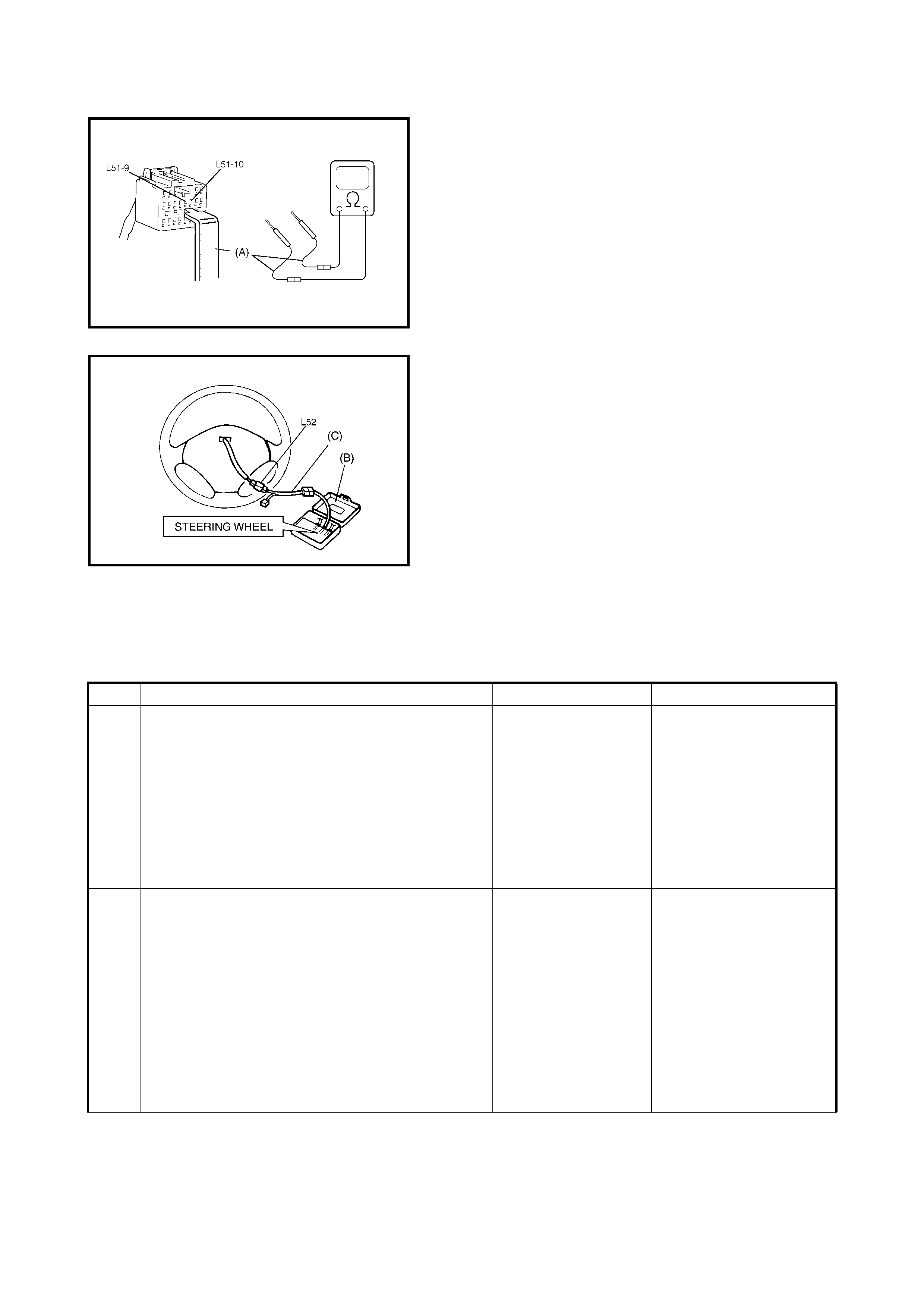
Fig. for STEP 2
Fig. for STEP 3 Special tool:
(A) 09932-76010
(B) 09932-75010
(C) 09932-78340
NOTE: Upon completion of inspection and repair work, perform following:
• Reconnect all airbag system components and ensure all components are properly mounted.
• Clear diagnostic trouble codes, refer to 2.7 DTC CLEARANCE in this Section, if any.
• Repeat 2.4 AIRBAG DIAGNOSTIC SYSTEM CHECK to confirm that the trouble has been corrected.
DTC B1022: Driver Airbag Initiator Circuit resistance Low
Step Action Yes No
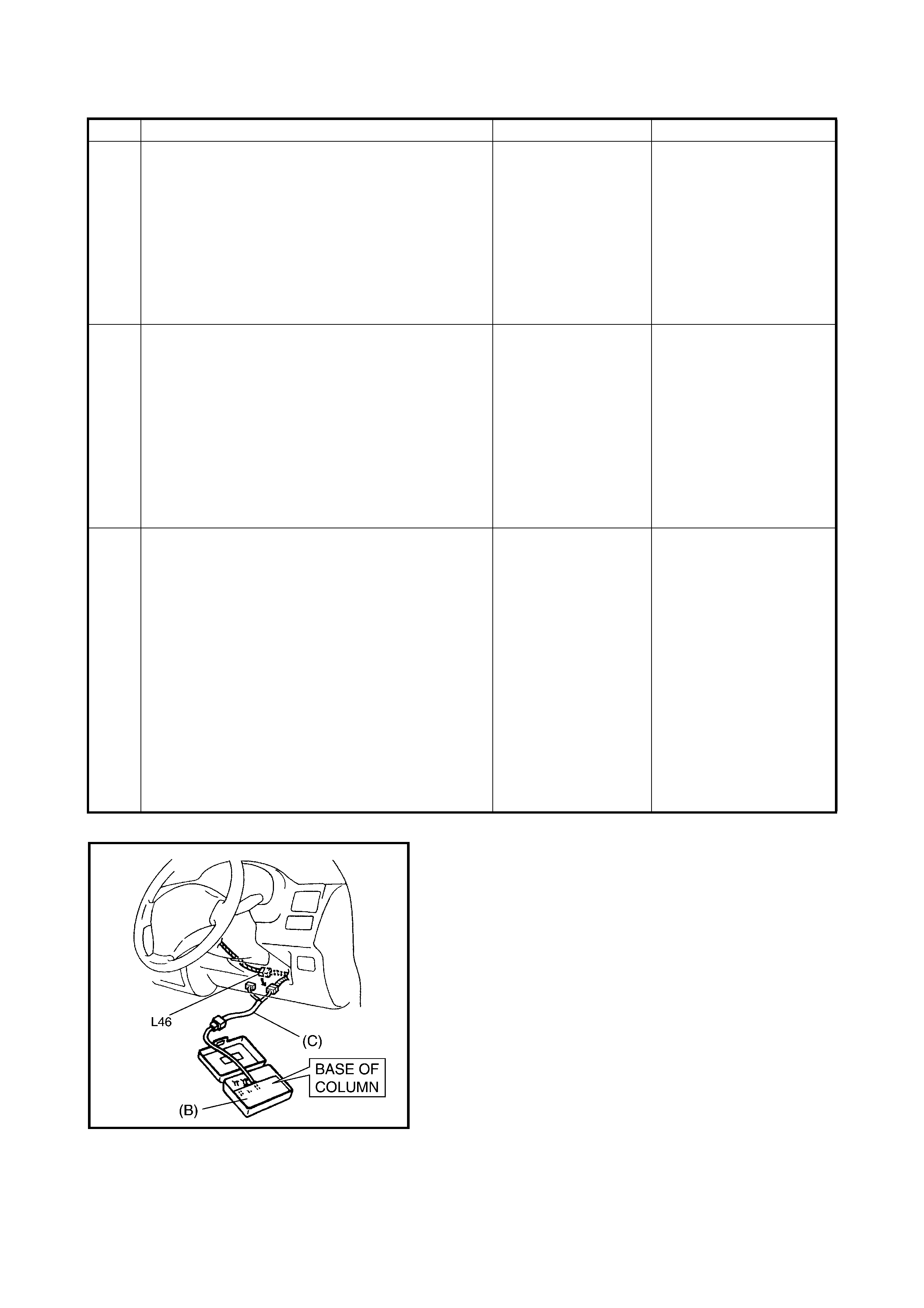
1 1. With ignition switch OFF, disconnect contact
coil connector located near the base of the
steering column.
2. Check proper connection to contact coil at
terminals in L46 connector.
3. If OK then connect special tools (B) and (C)
to contact coil connector, disconnected at
step 1.
With ignition switch ON, is DTC B1022 current?
Go to step 2. Go to step 3.
2 1. With ignition switch OFF, disconnect SDM
connector.
2. Check proper connection to SDM at
terminals L51-9 and L51-10.
3. If OK, release shorting bar in SDM
connector by inserting release tool incorpo-
rated in special tool (A).
4. Measure resistance between L51-9 and
L51-10 terminals with connected special
tools (B) and (C) to L46 connector.
Is resi stan c e 1.7 Ω or more?
Substitute a known-
good SDM and
recheck.
Repair short from GRN
wire circuit to GRN/RED
wire circuit or from GRN
or GRN/RED wire circuit
to other wire circuit.
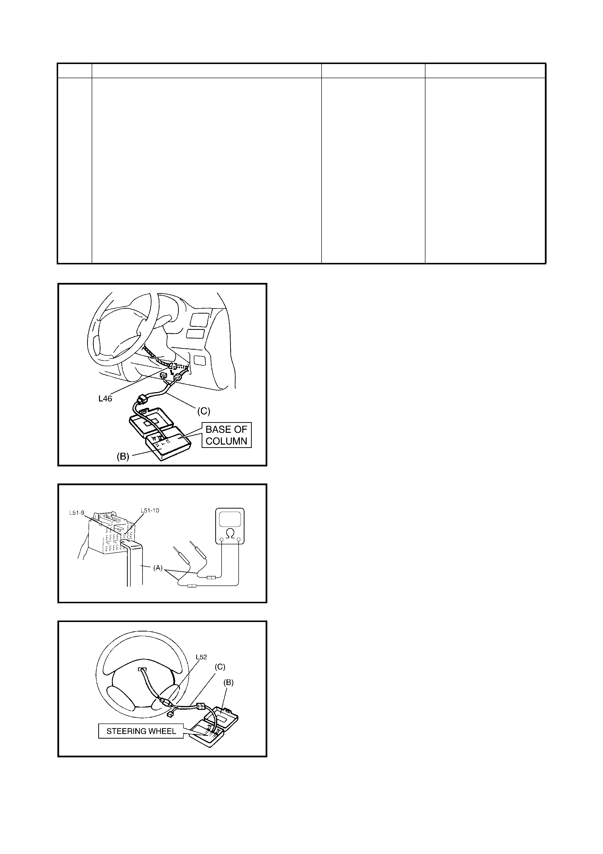
Fig. for STEP 1 and 2
Fig. for STEP 2
Fig. for STEP 3 Special tool:
(A) 09932-76010
(B) 09932-75010
(C) 09932-78340
NOTE: Upon completion of inspection and repair work, perform following:
• Reconnect all airbag system components and ensure all components are properly mounted.
• Clear diagnostic trouble codes, refer to 2.7 DTC CLEARANCE in this Section, if any.
• Repeat 2.4 AIRBAG DIAGNOSTIC SYSTEM CHECK to confirm that the trouble has been corrected.
3 1. With ignition switch OFF, disconnect special
tools (B) and (C) from L46 connector, then
reconnect contact coil connector located near
the base of the steering column.
2. Remove driver airbag (inflator) module from
steering wheel, refer to 3.2 DRIVER
AIRBAG (INFLATOR) MODULE in Section
3C.
3. Check proper connection to driver airbag
(inflator) module at terminals in L52
connector.
4. If OK then connect special tools (B) and (C)
to L52 connector.
With ignition switch ON, is DTC B1022 current?
Ignition switch OFF.
Replace contact coil
asse mbly, refer to
3.5 CONTACT COIL
AND COMBINATION
SWITCH
ASSEMB LY in
Section 3C.
Ignition switc h OFF.
Replace driv er airbag
(inflator) module, refer to
3.2 DRIVER AIRBAG
(INFLATOR) MODULE in
Section 3C.
Step Action Yes No
DTC B1024: Driver Airbag Initia tor Circuit Short to Ground
Fig. for STEP 1 and 2
Step Action Yes No
1 1. With ignition switch OFF, disconnect contact
coil connector located near the base of the
steering column.
2. Check proper connection to contact coil at
terminals in L46 connector.
3. If OK then connect special tools (B) and (C)
to contact coil connector disconnected at
step 1.
With ignition switch ON, is DTC B1024 current?
Go to step 2. Go to step 3.
2 1. With ignition switch OFF, disconnect special
tools (B) and (C) from L46 connector and
SDM connector from SDM.
2. Release shorting bar in SDM connector by
inserting release tool incorporated in special
tool (A).
3. Measure resistance between L51-9 terminal
and body ground and between L51-10
terminal and body ground.
Are they 1M Ω or more?
Substitute a known-
good SDM and
recheck.
Repair short from GRN or
GRN/RED wire circuit to
ground.
3 1. With ignition switch OFF, disconnect special
tools (B) and (C) from L46 connector, then
reconnect contact coil connector located near
the base of the steering column.
2. Remove driver airbag (inflator) module from
steering wheel, refer to 3.2 DRIVER
AIRBAG (INFLATOR) MODULE in Section
3C.
3. Check proper connection to driver airbag
(inflator) module at terminals in L52
connector.
4. If OK then connect special tools (B) and (C)
to L52 connector.
With ignition switch ON, is DTC B1024 current?
Ignition switch OFF.
Replace contact coil
asse mbly, refer to
3.5 CONTACT COIL
AND COMBINATION
SWITCH
ASSEMB LY in
Section 3C.
Ignition switc h OFF.
Replace driv er airbag
(inflator) module, refer to
3.2 DRIVER AIRBAG
(INFLATOR) MODULE in
Section 3C.
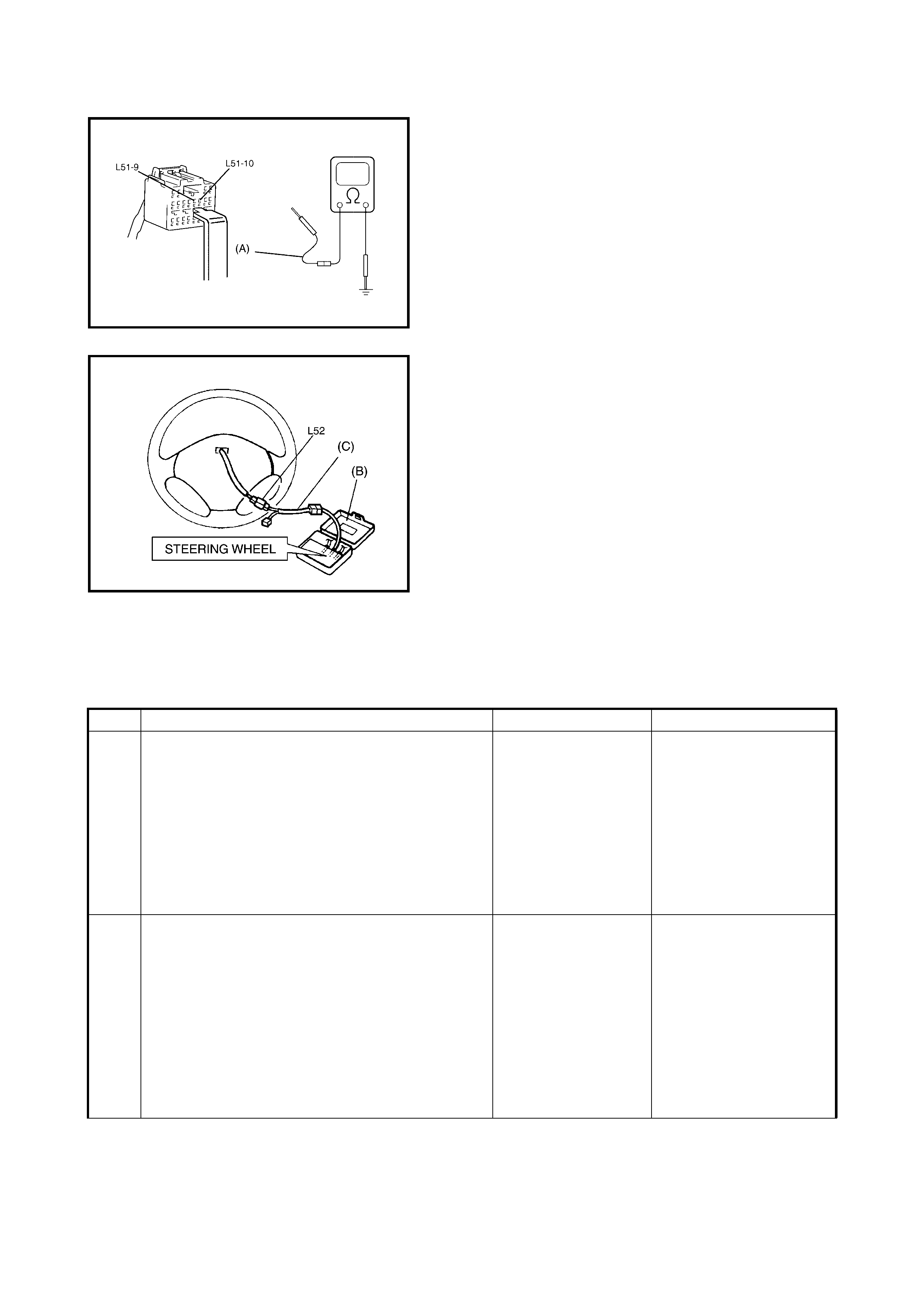
Fig. for STEP 2
Fig. for STEP 3 Special tool:
(A) 09932-76010
(B) 09932-75010
(C) 09932-78340
NOTE: Upon completion of inspection and repair work, perform following:
• Reconnect all airbag system components and ensure all components are properly mounted.
• Clear diagnostic trouble codes, refer to 2.7 DTC CLEARANCE in this Section, if any.
• Repeat 2.4 AIRBAG DIAGNOSTIC SYSTEM CHECK to confirm that the trouble has been corrected.
DTC B1025:Driver Airbag Initiator Circuit Short to Power Circuit
Step Action Yes No
1 1. With ignition switch OFF, disconnect contact
coil connector located near the base of the
steering column.
2. Check proper connection to contact coil at
terminals in L46 connector.
3. If OK then connect special tools (B) and (C)
to contact coil connector, disconnected at
step 1).
With ignition switch ON, is DTC B1025 current?
Go to step 2. Go to step 3.
2 1. With ignition switch OFF, disconnect special
tools (B) and (C) from L46 connector and
SDM connector from SDM.
2. Release shorting bar in SDM connector by
inserting release tool incorporated in special
tool (A).
3. Measure voltage from L51-9 terminal to
body ground and from L51-10 terminal to
body ground.
With ignition switch ON, are they 1 V or less?
Substitute a known-
good SDM and
recheck.
Repair short from GRN or
GRN/RED wire circuit to
power circuit.
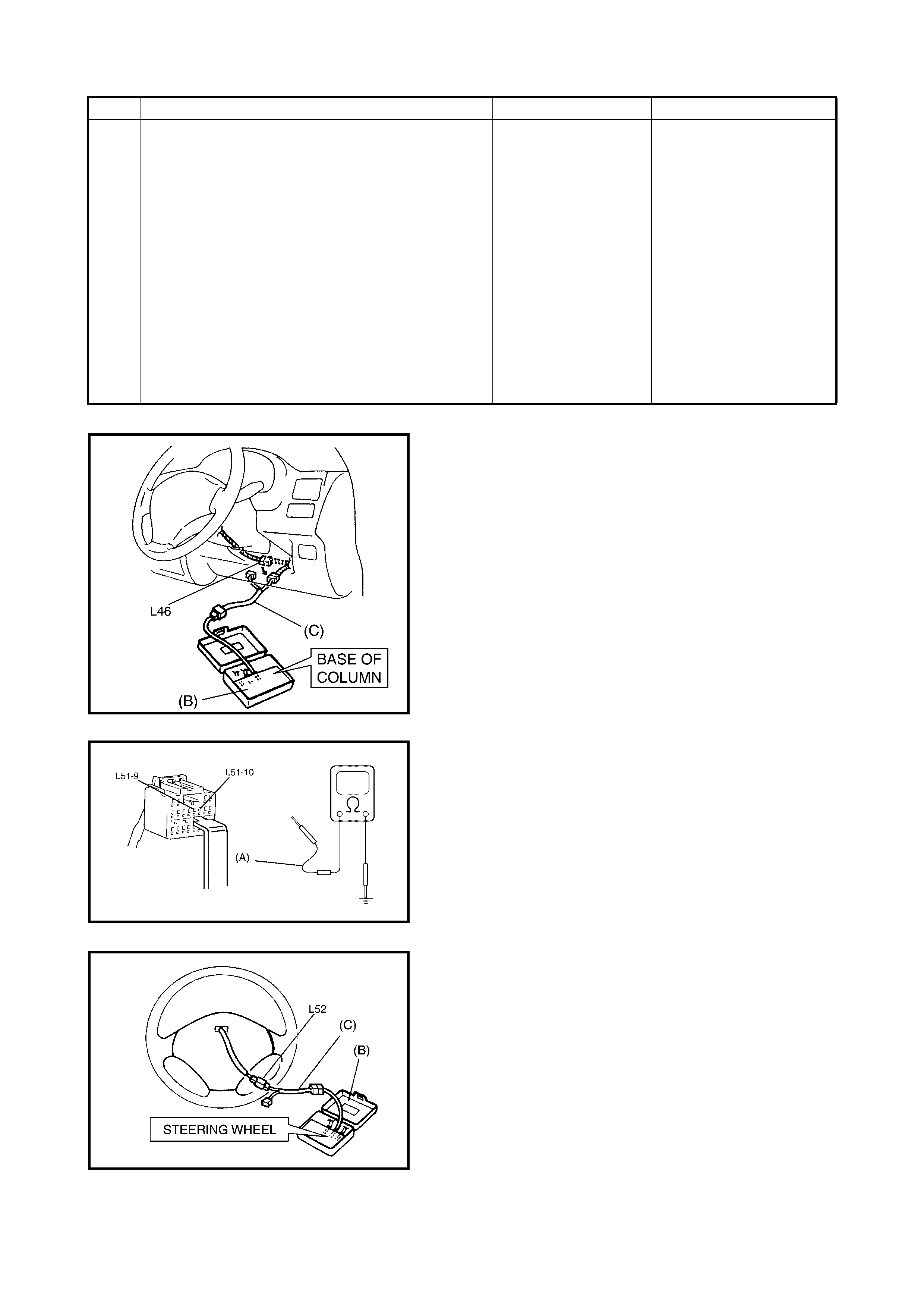
Fig. for STEP 1 and 2
Fig. for STEP 2
Fig. for STEP 3
Special tool:
(A) 09932-76010
(B) 09932-75010
(C) 09932-78340
NOTE: Upon completion of inspection and repair work, perform following:
• Reconnect all airbag system components and ensure all components are properly mounted.
• Clear diagnostic trouble codes, refer to 2.7 DTC CLEARANCE in this Section, if any.
• Repeat 2.4 AIRBAG DIAGNOSTIC SYSTEM CHECK to confirm that the trouble has been corrected.
3 1. With ignition switch OFF, disconnect special
tools (B) and (C) from L46 connector then
reconnect contact coil connector located near
the base of the steering column.
2. Remove driver airbag (inflator) module from
steering wheel, refer to 3.2 DRIVER
AIRBAG (INFLATOR) MODULE in Section
3C.
3. Check proper connection to driver airbag
(inflator) module at terminals in L52
connector.
4. If OK then connect special tools (B) and (C)
to L52 connector.
With ignition switch ON, is DTC B1025 current?
Ignition switch OFF.
Replace contact coil
asse mbly, refer to
3.5 CONTACT COIL
AND COMBINATION
SWITCH
ASSEMB LY in
Section 3C.
Ignition switc h OFF.
Replace driv er airbag
(inflator) module, refer to
3.2 DRIVER AIRBAG
(INFLATOR) MODULE in
Section 3C.
Step Action Yes No
2.22 DTC B1 031 – POWER SOURCE VOLTAGE HIGH
Please refer to 2.23 DTC B1032 - POWER SOURCE VOLTAGE LOW for DTC information.
2.23 DTC B1032 – POWER SO URCE VOLTAGE LOW
WIRING DIAGRAM
Legend
CAUTION:
•Perform 2.4 AIRBAG DIAGNOSTIC SYSTEM CHECK before starting diagnosis according to flow
table.
• When measur ement of resistance or voltage is required in this table, use a specified digital multi-
meter along with a correct terminal adapter from the connector test adapter kit, refer
5. SPECIAL TOOLS in this Section.
• When a check for proper connection is required, refer to 2.3 INTERMITTENTS AND
POOR CONNECTIONS in this Section.
• If there is ope n circuit in the airba g wire h arness, c onnect or or te rmin al is found dama ged, repla ce
the wire harness, connector and terminal as an assembly.
DTC WILL SET WHEN
DTC B1031:The power source voltage to the SDM is above a specified value for a specified time.
DTC B1032:The power source voltage to the SDM is below a specified value for a specified time.
TABLE TEST DESCRIPTION
DTC B1031:
STEP 1: Check if voltage applied to SDM is within normal range.
STEP 2: Check if DTC B1031 still exists.
DTC B1032:
STEP 1: Check if voltage applied to SDM is within normal range.
STEP 2: Check if DTC B1032 still exists.
DTC B1031: Power Source Voltage High
[A]: Airbag harness in floor harness 2. Ignition switch 4. SDM
1. From main fuse 3. Airbag fuse 5. Ground for airbag system
Step Action Yes No
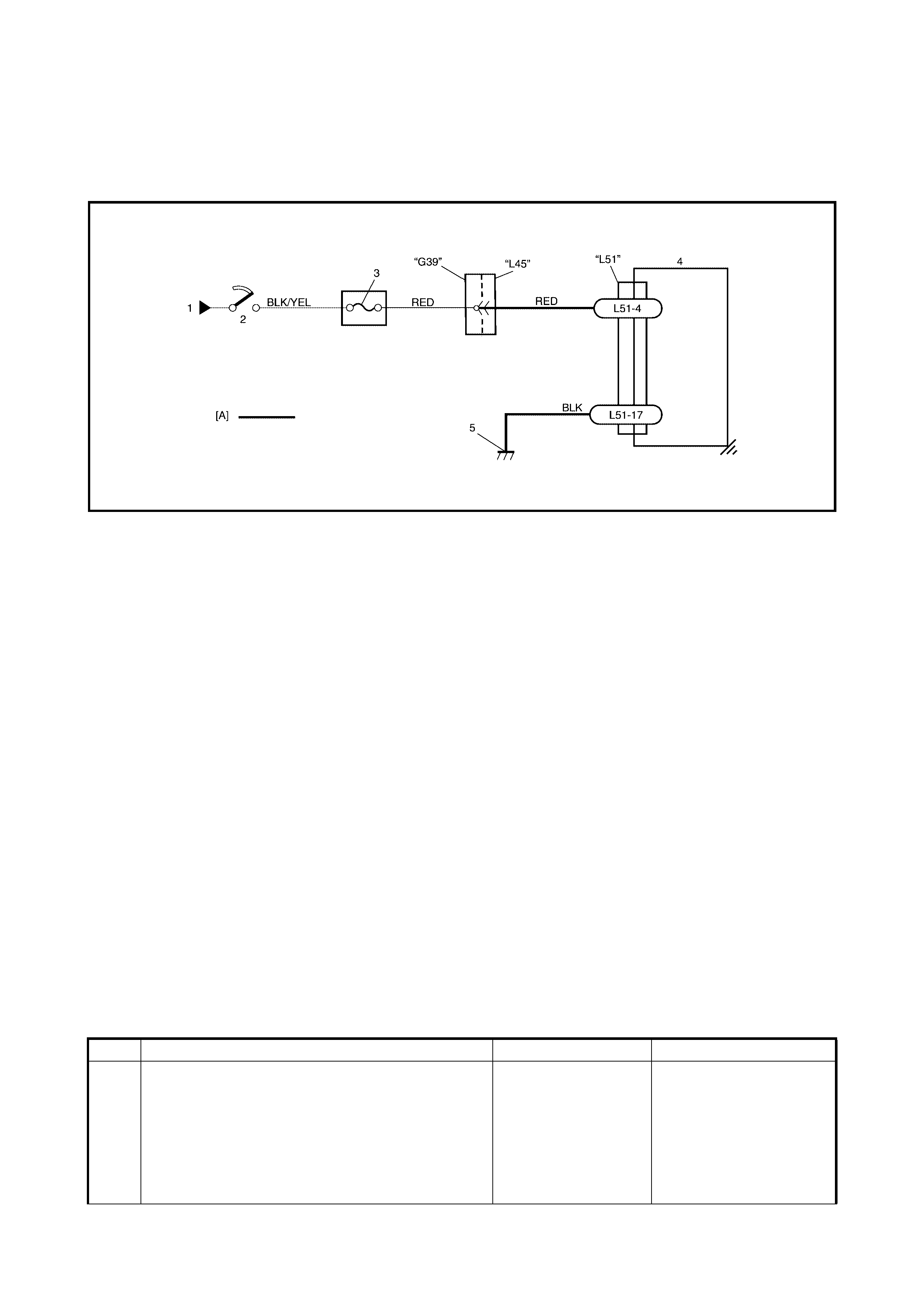
1 1. With ignition OFF, disconnect SDM connector.
2. Check proper connection to SDM at L51-04
terminal.
3. If OK. turn ignition switch ON and then check
voltage from L51-04 terminal on SDM
connector to body ground.
Is voltage 17 V or less?
Go to step 2. Check Charging System
and repair as necessary,
refe r to 2. DIAG NOSIS in
Section 6H.
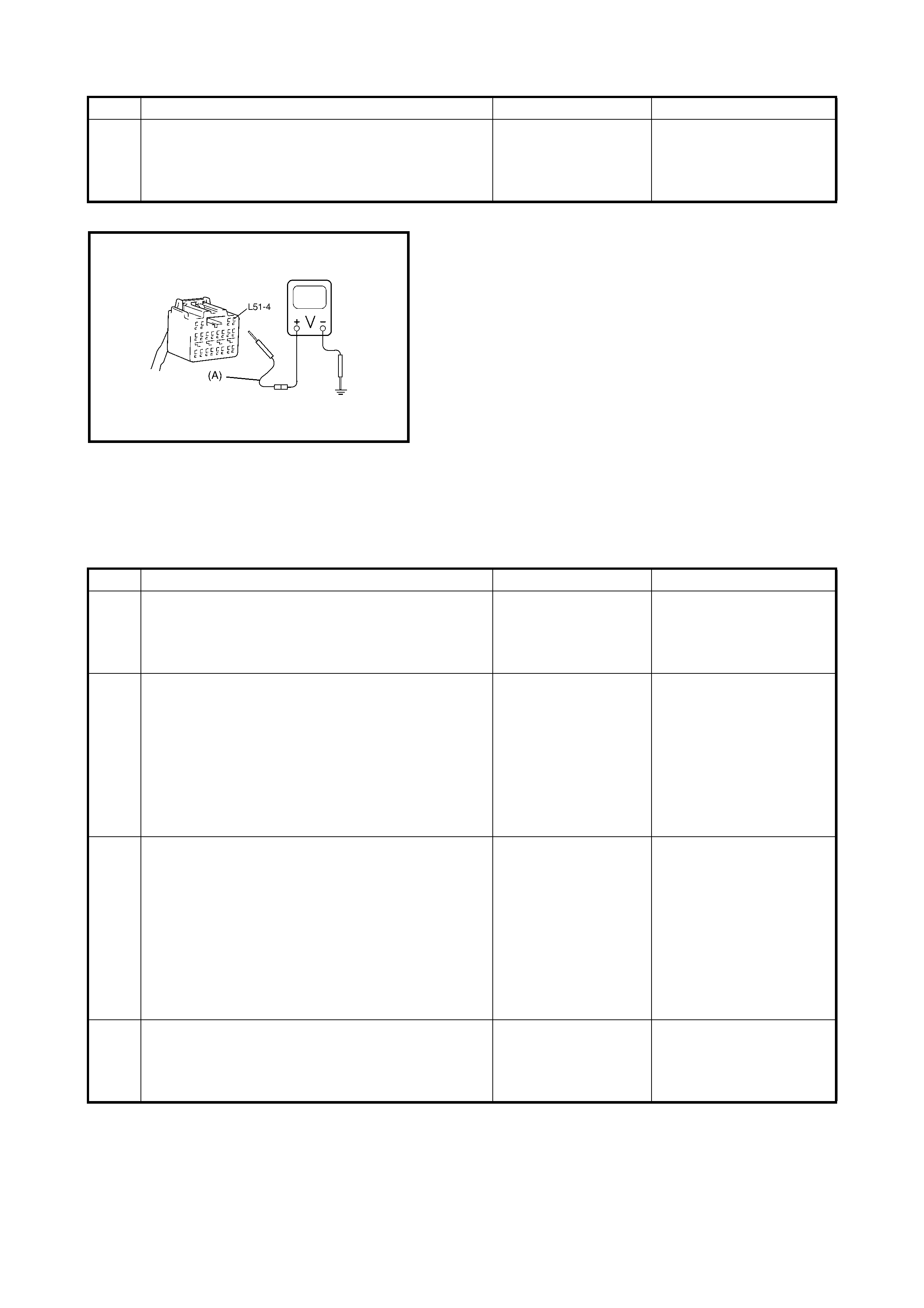
Fig. for STEP 2 Special Tool:
(A) 09932-76010
NOTE: Upon completion of inspection and repair work, perform following:
• Reconnect all airbag system components and ensure all components are properly mounted.
• Clear diagnostic trouble codes, refer to 2.7 DTC CLEARANCE in this Section, if any.
• Repeat 2.4 AIRBAG DIAGNOSTIC SYSTEM CHECK to confirm that the trouble has been corrected.
DTC B1032: Power Source Voltage Low
2 1. With ignition switch OFF, reconnect SDM
connector.
With ignition switch ON, is DTC B1031 current?
Substitute a known-
good SDM and
recheck.
Check Charging System
and repair as necessary,
refe r to 2. DIAG NOSIS in
Section 6H.
Step Action Yes No
Step Action Yes No
1 1. Measure voltage on battery.
Is voltage 11 V or more? Go to step 2. Check Charging System
and repair as necessary,
refe r to 2. DIAG NOSIS in
Section 6H.
2 1. With ignition switch OFF, disconnect SDM
connector.
2. Check proper connection to SDM at L51-4
terminal.
3. If OK then ignition switch ON, and then
check voltage from L51-4 terminal on SDM
connector to body ground.
Is voltage 6 V or more?
Go to step 4. Go to step 3.
3 1. With ignition switch OFF, disconnect G39
connector.
2. Check proper connection at G39-1 (RED
wire) terminal.
3. If OK then turn the ignition switch ON, and
then check voltage from G39-1 (RED wire)
terminal on instrument panel harness to
body ground.
Is voltage 6 V or more?
Repair poor connec-
tion, high resistance
in RED or BLK/YEL
circuit of airbag har-
ness or airbag fuse.
Possible faulty points are
as follows. Check each
and repair as necessary.
• Circuit from battery to
G39 connector
• Charging System,
refer to 2. DIAGNO-
SIS in Secti on 6H.
4 1. With ignition switch OFF, reconnect SDM
connector.
With ignition switch ON, is DTC B1032 current?
Substitute a known-
good SDM and
recheck.
Check Charging System
and repair as necessary,
refe r to 2. DIAG NOSIS in
Section 6H.
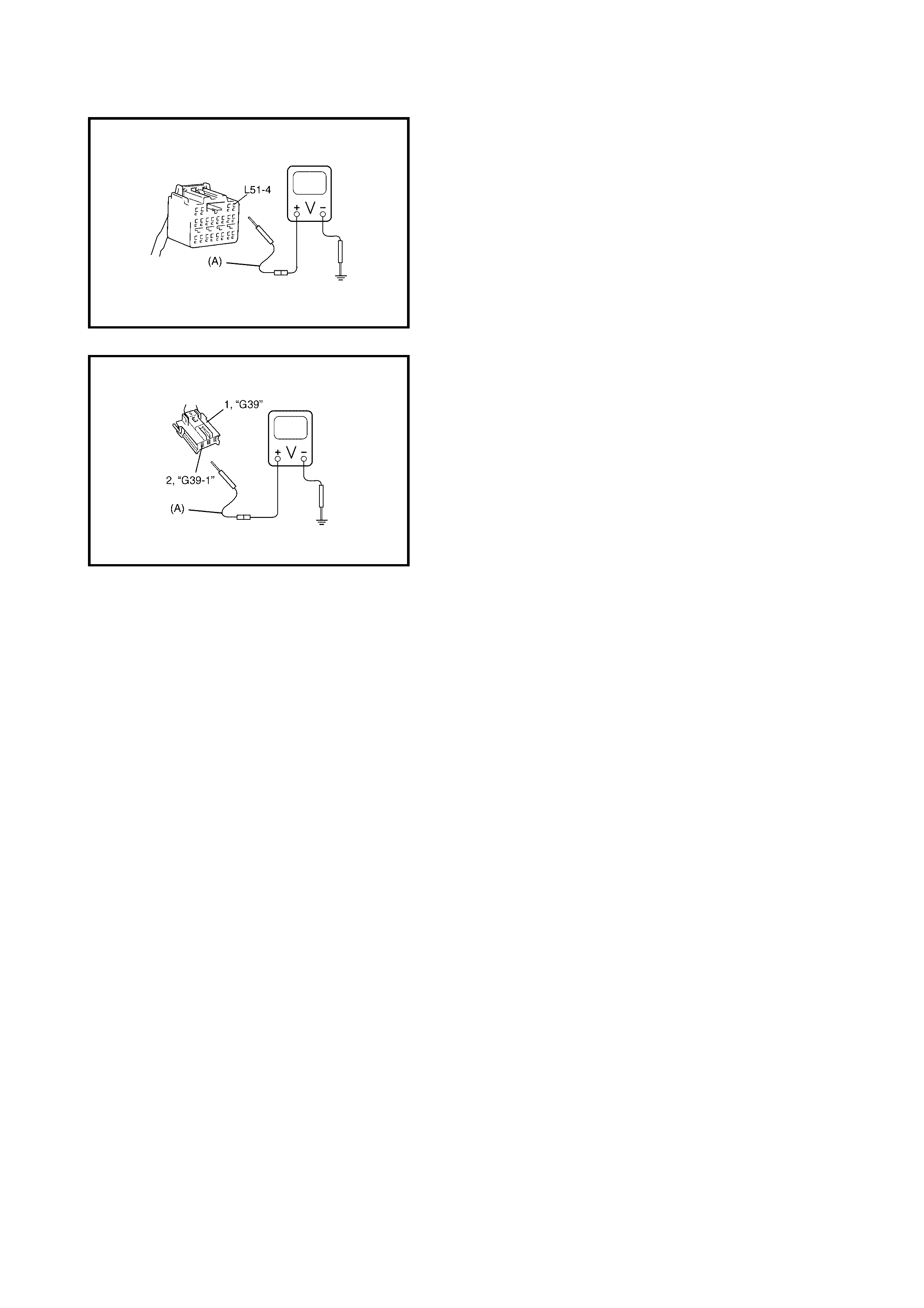
Fig. for STEP 2
Fig. for STEP 3 Legend
Special Tool:
(A) 09932-76010
NOTE: Upon completion of inspection and repair work, perform following:
• Reconnect all airbag system components and ensure all components are properly mounted.
• Clear diagnostic trouble codes, refer to 2.7 DTC CLEARANCE in this Section, if any.
• Repeat 2.4 AIRBAG DIAGNOSTIC SYSTEM CHECK to confirm that the trouble has been corrected.
1. Instrument panel harness side connector
2. RED wire terminal
2.24 DTC B1041 – DRIVER PRETENSIONER INITIATOR CIRCUIT RESISTANCE HIGH
Please refer to 2.31 DTC B1048 – PASSENGER PRETENSIONER INITIATOR CIRCUIT SHORT TO
POWER CIRCUIT for DTC information.
2.25 DTC B10 42 – DRIVER PRETENSIONER INITIATOR CIRCUIT RES I STANCE LOW
Please refer to 2.31 DTC B1048 – PASSENGER PRETENSIONER INITIATOR CIRCUIT SHORT TO
POWER CIRCUIT for DTC information.
2.26 DTC B1043 – DRIVER PRETENSIONER INITIATOR CIRCUIT SHORT TO GROUND
Please refer to 2.31 DTC B1048 – PASSENGER PRETENSIONER INITIATOR CIRCUIT SHORT TO
POWER CIRCUIT for DTC information.
2.27 DTC B1044 – DRIVER PRETENSIONER INITIATOR CIRCUIT
SHORT TO POWER CIRCUIT
Please refer to 2.31 DTC B1048 – PASSENGER PRETENSIONER INITIATOR CIRCUIT SHORT TO
POWER CIRCUIT for DTC information.
2.28 DTC B1045 – PASSENGER PRETENSIONER INITIATOR
CIRCUIT RESISTANCE HIGH
Please refer to 2.31 DTC B1048 – PASSENGER PRETENSIONER INITIATOR CIRCUIT SHORT TO
POWER CIRCUIT for DTC information.
2.29 DTC B1046 – PASSENGER PRETENSIONER INITIATOR
CIRCUIT RESISTANCE LOW
Please refer to 2.31 DTC B1048 – PASSENGER PRETENSIONER INITIATOR CIRCUIT SHORT TO
POWER CIRCUIT for DTC information.
2.30 DTC B1047 – PASSENGER PRETENSIONER INITIATOR
CIRCUIT SHORT TO GROUND
Please refer to 2.31 DTC B1048 – PASSENGER PRETENSIONER INITIATOR CIRCUIT SHORT TO
POWER CIRCUIT for DTC information.
2.31 DTC B1048 – PASSENGER PRETENSIONER INITIATOR
CIRCUIT SHORT TO POWER CIRCUIT
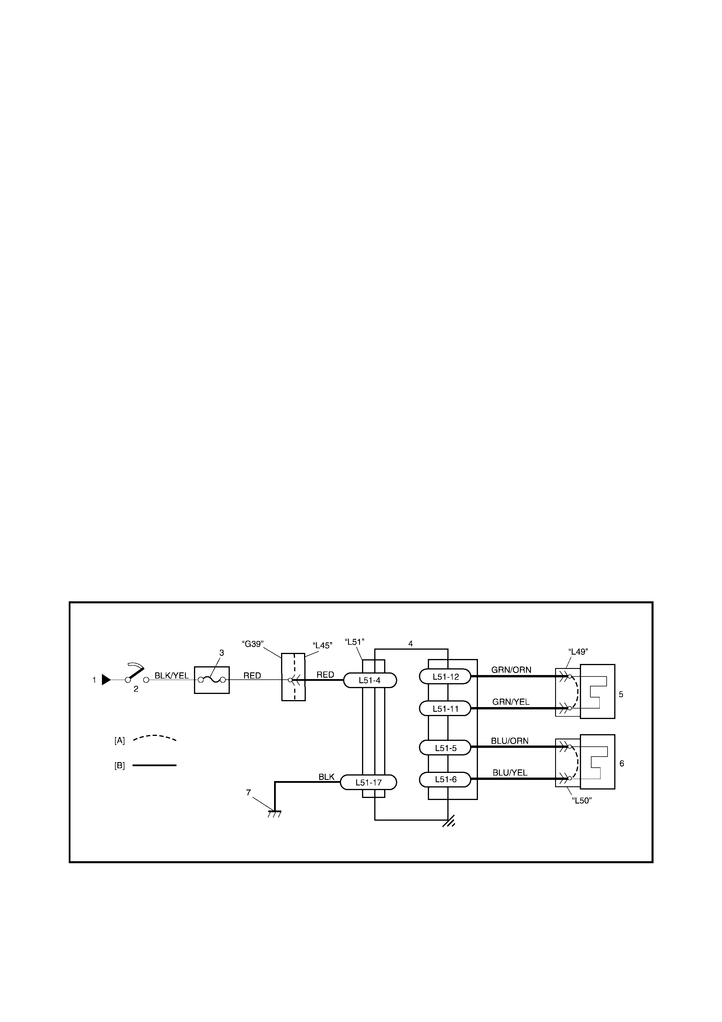
WIRING DIAGRAM
[A]: Shorting bar 2. Ignition switch 5. Driver seat belt pretensioner
[B]: Airbag harness in floor harness 3. Airbag fuse 6. Passenger seat belt pretensioner
1. From main fuse 4. SDM 7. Ground for airb ag system

CAUTION:
•Perform 2.4 AIRBAG DIAGNOSTIC SYSTEM CHECK before starting diagnosis according to flow
table.
• When measurement of resistance or voltage is required in this table, use a specified digital
multimeter along with a correct terminal adapter from the connector test adapter kit, refer
5. SPECIAL TOOLS in this Section.
• When a check for proper connection is required, refer to 2.3 INTERMITTENTS AND
POOR CONNECTIONS in this Section.
• If there is ope n circuit in the airba g wire h arness, c onnect or or te rmin al is found dama ged, repla ce
the wire harness, connector and terminal as an assembly.
DTC WILL SET WHEN
DTC B1041 and B1045:
The resistance of the driver or passenger seat belt pretensioner initiator circuit is above a specified value for a
specified time.
DTC B1042 and B1046:
The resistance of the driver or passenger seat belt pretensioner initiator circuit is below a specified value for a
specified time.
DTC B1043 and B1047:
The voltage measured at the driver or passenger seat belt pretensioner initiator circuit is below a specified
value for a specified time.
DTC B1044 and B1048:
The voltage measured at the driver or passenger seat belt pretensioner initiator circuit is above a specified
value for a specified time.
TABLE TEST DESCRIPTION
DTC B1041, B1042, B1043, B1044, B1045, B1046, B1047 and B1048:
STEP 1: Check whether malfunction is in the seat belt pretensioner.
STEP 2: Check the seat belt pretensioner initiator circuit in the airbag harness.
DIAGNOSTIC FLOW TABLE
DTC B1041: Driver Pretensioner Initiator Circuit Resistance High and
DTC B1045: Passenger Pretensioner Initiator Circuit Resistance High
Step Action Yes No
1 1. With ignition switch OFF, remove centre
pillar inner garnish of applicable side then
disconnect seat belt pretensioner L49 or L50
connector.
2. Check proper connection to applicable seat
belt pretensioner at terminals in L49 or L50
connector.
3. If OK then connect special tools (A), (B) and
(C) to seat belt pretensioner connector L49
or L50 disconnected at the step 1.
With ignition switch ON, is DTC B1041 or B1045
still current?
Go to step 2. Ignition switch OFF.
Replace se at belt preten-
sioner, refer to
3.2 FRONT SEAT BELT
ASSEMBLY in Section
10.
2 1. With ignition switch OFF, disconnect SDM
connector.
2. Check proper connection to SDM at
terminals L51-11 and L51-12 or L51-6 and
L51-5.
3. If OK, measure resistance between L51-11
and L51-12 terminals or L51-6 and L51-5
terminals with connected special tools (A),
(B) and (C) to the applicable pretensioner in
L49 or L50 connec to r.
Is resi stan c e 4.5 Ω or less?
Substitute a known-
good SDM and
recheck.
DTC B1041:
Repair high resistance or
open in GRN/ORN or
GRN/YEL wire circuit.
DTC B1045:
Repair high resistance or
open in BL U/ YE L or BLU/
ORN wire circuit.
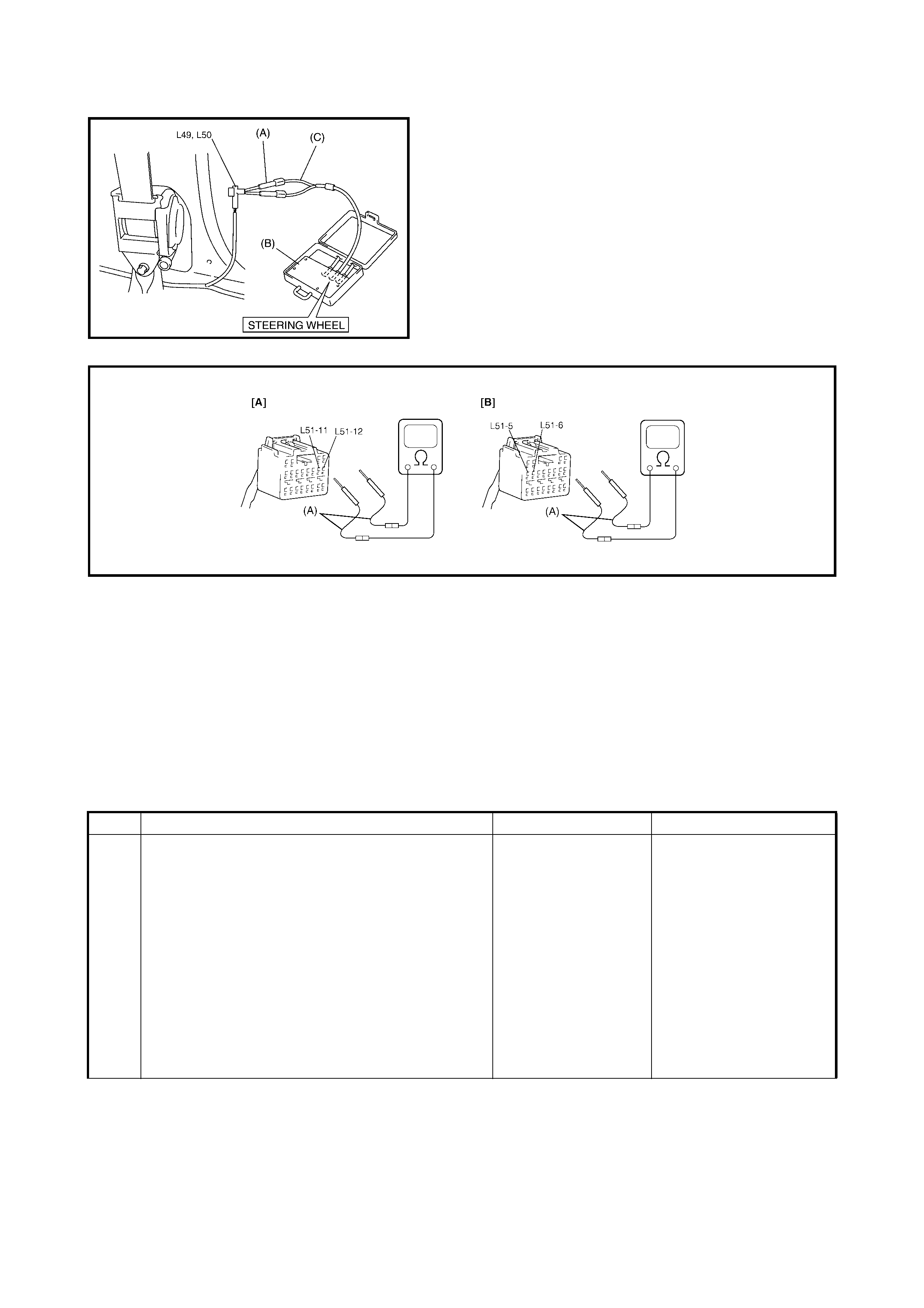
Fig. for STEP 1 and 2
Fig. for STEP 2
Legend
NOTE: Upon completion of inspection and repair work, perform following:
• Reconnect all airbag system components and ensure all components are properly mounted.
• Clear diagnostic trouble codes, refer to 2.7 DTC CLEARANCE in this Section, if any.
• Repeat 2.4 AIRBAG DIAGNOSTIC SYSTEM CHECK to confirm that the trouble has been corrected.
DTC B1042: Driver Pretensioner Initiator Circuit Resistance Low and
B1046: Driver Pretensioner Initiator Circuit Resistance High
[A]: For DTC B1041
(B): Special tool 09932-75010
[B]: For DTC B1045
(C): Special tool 09932-78310
(A): Special tool 09932-76010
Step Action Yes No
1 1. With ignition switch OFF, remove centre
pillar inner garnish of applicable side then
disconnect seat belt pretensioner L49 or L50
connector.
2. Check proper connection to applicable seat
belt pretensioner at terminals in L49 or L50
connector.
3. If OK then connect special tools (A), (B) and
(C) to seat belt pretensioner L49 or L50
connector, disconnected at the step 1.
With ignition switch ON, is DTC B1042 or B1046
still current?
Go to step 2. Ignition switch OFF.
Replace se at belt preten-
sioner, refer to
3.2 FRONT SEATBELT
ASSEMBLY in Section
10.
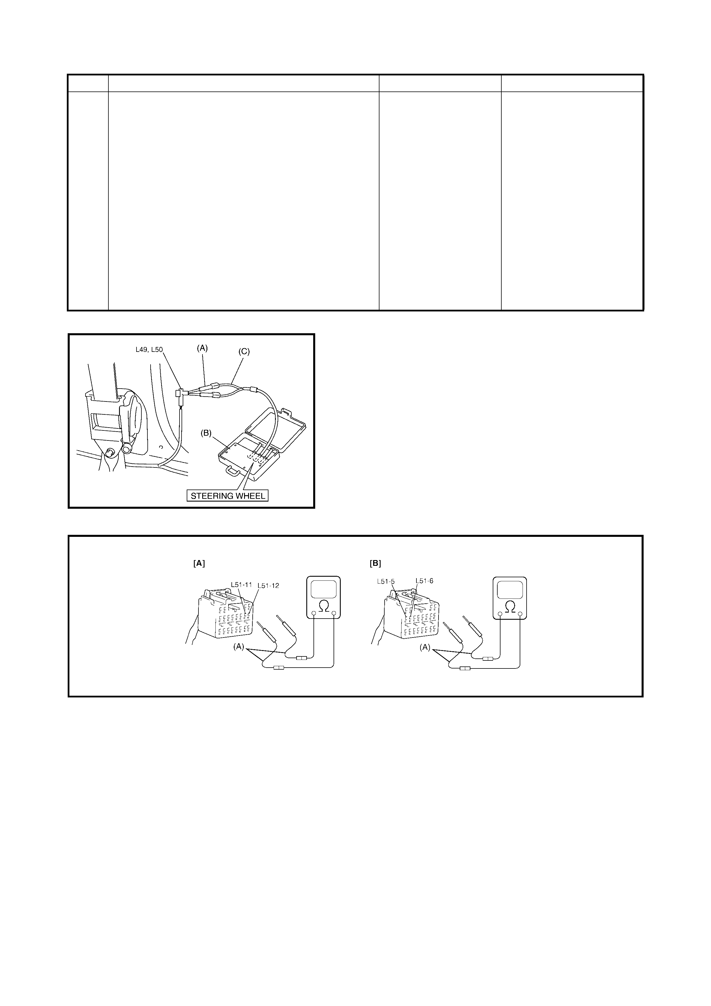
Fig. for STEP 1 and 2
Fig. for STEP 2
Legend
NOTE: Upon completion of inspection and repair work, perform following:
• Reconnect all airbag system components and ensure all components are properly mounted.
• Clear diagnostic trouble codes, refer to 2.7 DTC CLEARANCE in this Section, if any.
• Repeat 2.4 AIRBAG DIAGNOSTIC SYSTEM CHECK to confirm that the trouble has been corrected.
2 1. With ignition switch OFF, disconnect SDM
connector.
2. Check proper connection to SDM at
terminals L51-11 and L51-12 or L51-6 and
L51-5.
3. If OK, measure resistance between L51-11
and L51-12 terminals or L51-6 and L51-5
terminals with connected special tools (A),
(B) and (C) to the applicable seat belt pre-
tensioner at terminal in L49 or L50
connector.
Is resi stan c e 1.4 Ω or more?
Substitute a known-
good SDM and
recheck.
DTC B1042:
Repair short from GRN/
ORN wire circuit to GRN/
YEL wire circuit or from
GRN/ORN or GRN/YEL
wire circuit to other wire
circuit.
DTC B1046:
Repair short from BLU/
YEL wire circuit to BLU/
ORN wire circuit or from
BLU/YEL or BLU/ORN
wire circuit to other wire
circuit.
Step Action Yes No
[A]: For DTC B1042
(B): Special tool 09932-75010
[B]: For DTC B1046
(C): Special tool 09932-78310
(A): Special tool 09932-76010
DTC B1043: Driver Pretensioner Initiator Circuit Short to Ground and B1047: Passenger Pre-
tensioner Initiator Circuit Short to Ground
Fig. for STEP 1 and 2
Fig. for STEP 2
Legend
NOTE: Upon completion of inspection and repair work, perform following:
• Reconnect all airbag system components and ensure all components are properly mounted.
• Clear diagnostic trouble codes, refer to 2.7 DTC CLEARANCE in this Section, if any.
• Repeat 2.4 AIRBAG DIAGNOSTIC SYSTEM CHECK to confirm that the trouble has been corrected.
Step Action Yes No
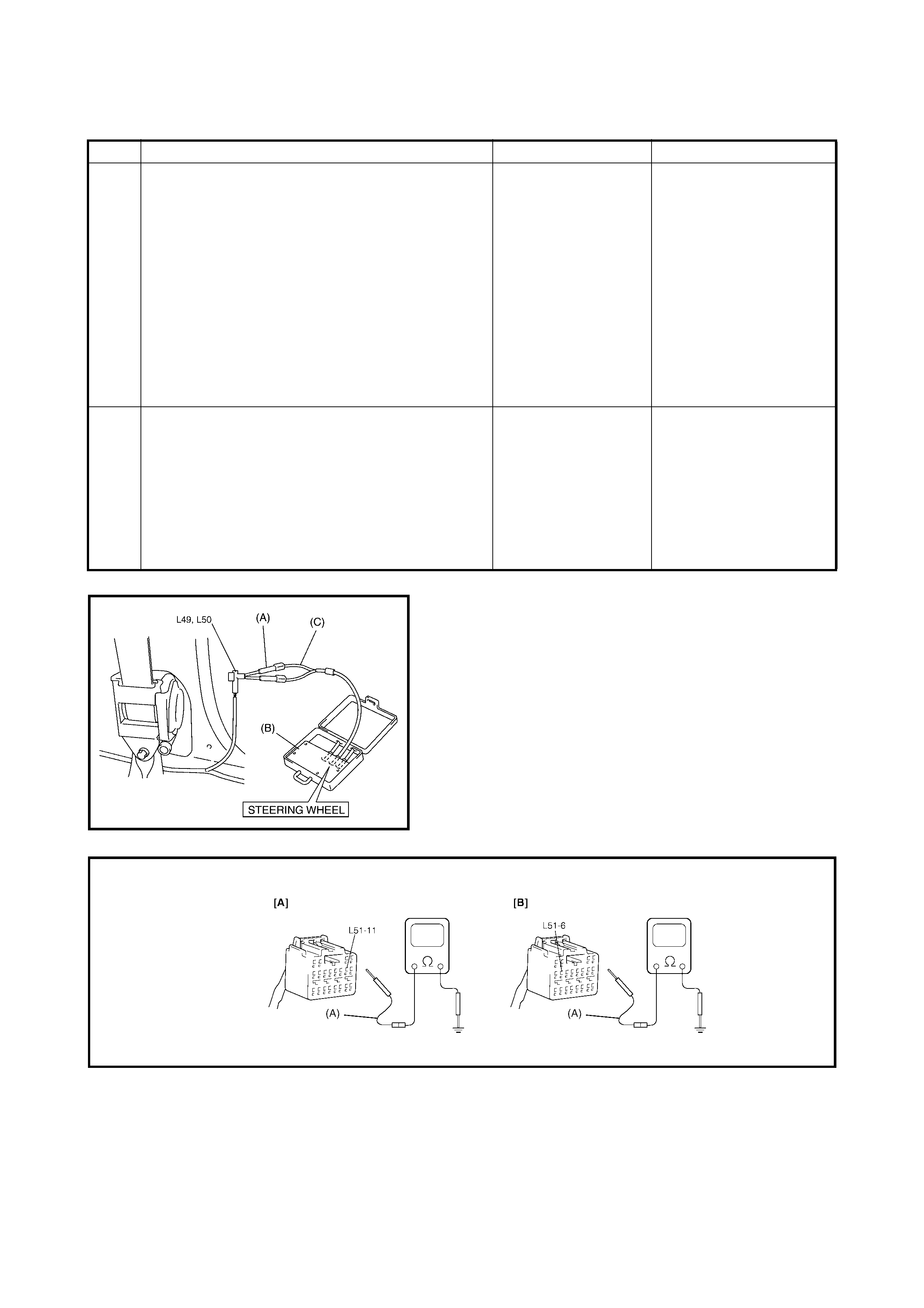
1 1. With ignition switch OFF, remove centre
pillar inner garnish of applicable side, then
disconnect seat belt pretensioner L49 or L50
connector.
2. Check proper connection to applicable seat
belt pretensioner at terminals in L49 or L50
connector.
3. If OK, connect special tools (A), (B) and (C)
to seat belt pretensioner L49 or L50
connector, disconnected at the step 1.
With ignition switch ON, is DTC B1043 or B1047
still current?
Go to step 2. Ignition switch OFF.
Replace se at belt preten-
sioner, refer to
3.2 FRONT SEAT BELT
ASSEMBLY in Section
10.
2 1. With ignition switch OFF, disconnect special
tools (A), (B) and (C) from L49 or L50
connector and SDM connector from SDM.
2. Measure resistance between L51-11 or L51-
6 and body ground.
Is resi sta nc e 1M Ω or more?
Substitute a known-
good SDM and
recheck.
DTC B1043:
Repair short GRN/YEL or
GRN/ORN wire circuit to
ground.
DTC B1047:
Repair short from BLU/
YEL or BLU/ORN wire
circuit to ground.
[A]: For DTC B1043
(B): Special tool 09932-75010
[B]: For DTC B1047
(C): Special tool 09932-78310
(A): Special tool 09932-76010
DTC B1044: Driver Pretensioner Initiator Circuit Short to Power and B1048:Passenger
Pretensioner Initiator Circuit Short to Power
Fig. for STEP 1 and 2
Fig. for STEP 2
Legend
NOTE: Upon completion of inspection and repair work, perform following:
• Reconnect all airbag system components and ensure all components are properly mounted.
• Clear diagnostic trouble codes, refer to 2.7 DTC CLEARANCE in this Section, if any.
• Repeat 2.4 AIRBAG DIAGNOSTIC SYSTEM CHECK to confirm that the trouble has been corrected.
Step Action Yes No
1 1. With ignition switch OFF, remove centre
pillar inner garnish of applicable side then
disconnect seat belt pretensioner L49 or L50
connector.
2. Check proper connection to applicable seat
belt pretensioner at terminals in L49 or L50
connector.
3. If OK then connect special tools (A), (B) and
(C) to seat belt pretensioner L49 or L50
connector, disconnected at the step 1.
With ignition switch ON, is DTC B1044 or B1048
still current?
Go to step 2. Ignition switch OFF.
Replace se at belt preten-
sioner, refer to
3.2 FRONT SEAT BELT
ASSEMBLY in Section
10.
2 1. With ignition switch OFF, disconnect special
tools (A), (B) and (C) from L49 or L50
connector and SDM connector from SDM.
2. Measure voltage from L51-12 or L51-5
terminal to body ground.
With ignit i on switch ON, is voltage 1 V or less?
Substitute a known-
good SDM and
recheck.
DTC B1044:
Repair short GRN/ORN
or GRN/YEL wire circuit
to power circui t.
DTC B1048:
Repair short from BLU/
YEL or BLU/ORN wire
circuit to power circuit.
[A]: For DTC B1044
(B): Special tool 09932-75010
[B]: For DTC B1048
(C): Special tool 09932-78310
(A): Special tool 09932-76010

2.32 DTC B1051 – FRONTAL CRASH DETECTED (SY STEM ACTIVATION COMMAND
OUTPUTTED)
CAUTION: Perform 2.4 AIRBAG DIAGNOSTIC SYSTEM CHECK before starting diagnosis according to
the flow table.
DTC WILL SET WHEN
The SDM detec ts a frontal crash of s ufficie nt for ce to w arra nt ac tivati on of the airba g syste m. (SDM outpu ts a
deployment command.)
TABLE TEST DESCRIPTION
STEP 1: Check that DTC B1051 has been set although airbag has not been deployed.
STEP 2: Check that DTC has been set due to failure of SDM.
NOTE: Before executing items in this table, perform 2.4 AIRBAG DIAGNO STIC SYSTEM CHECK.
NOTE: Upon completion of inspection and repair work, perform following:
• Reconnect all airbag system components and ensure all components are properly mounted.
• Repeat 2.4 AIRBAG DIAGNOSTIC SYSTEM CHECK to confirm that the trouble has been corrected.
2.33 DTC B1071 - INTE RNAL SDM FAULT
DTC WILL SET WHEN
An internal SDM fault is detected by the SDM.
CAUTION: Perform 2.4 AIRBAG DIAGNOSTIC SYSTEM CHECK before starting diagnosis according to
the flow table.
NOTE: DTC B1071 can never be cleared once it has been set.
1. Turn ignition switch OFF.
2. Replace SDM.
3. Repeat 2.4 AIRBAG DIAGNOSTIC SYSTEM CHECK.
Step Action Yes No
1 1. Ignition switch OFF.
Has airbag system deployed? Replace components
and perform
inspections as
directed in
3.2 REPAIRS AND
INSPECTIONS
REQUIRED AFTER
A COLLISION.
Go to step 2.
2 1. Inspect front of vehicle and undercarriage for
signs of impact.
Are there signs of impact?
Replace components
and perform
inspections as
directed in
3.2 REPAIRS AND
INSPECTIONS
REQUIRED AFTER
A COLLISION.
Substitute a known-good
SDM and recheck.
2.34 DTC – B1061 AIRBAG WARNING LAMP CIRCUIT FAILURE
WIRING DIAGRAM
Legend
CAUTION:
•Perform 2.4 AIRBAG DIAGNOSTIC SYSTEM CHECK before starting diagnosis according to flow
table.
• When measur ement of resistance or voltage is required in this table, use a specified digital multi-
meter along with a correct terminal adapter from the connector test adapter kit, refer
5. SPECIAL TOOLS in this Section.
• When a check for proper connection is required, refer to 2.3 INTERMITTENTS AND
POOR CONNECTIONS in this Section.
• If there is ope n circuit in the airba g wire h arness, c onnect or or te rmin al is found dama ged, repla ce
the wire harness, connector and terminal as an assembly.
DTC WILL SET WHEN
The v oltage at the AIRBA G warning lamp circ uit termina l L51-2 does not match the comm anded state of th e
warning lamp driver for the specified time.
TABLE TEST DESCRIPTION
STEP 1: This test rechecks AIRBAG warning lamp operation.
STEP 2: This test rechecks whether an abnormality is in the SDM.
[A]: Airbag harness in floor harness 6. Connection detection pin
1. From main fuse 7. SDM
2. Ignition switch 8. To DLC
3. METER fuse 9. To ECM, TCM and ABS control module (if equipped)
4. Airbag warning lamp in combination lamp 10. Airbag diagnosis connector No. 3
5. Airbag fuse 11. Ground for airbag system

DIAGNOSTIC FLOW TABLE
NOTE: Upon completion of inspection and repair work, perform following:
• Reconnect all airbag system components and ensure all components are properly mounted.
• Repeat 2.4 AIRBAG DIAGNOSTIC SYSTEM CHECK to confirm that the trouble has been corrected.
Step Action Yes No
1 1. This DTC is set when there is a trouble in the
AIRBAG warning lamp circuit. Failure to
properly perform 2.4 AIRBAG DIAGNOSTIC
SYSTEM CHECK may also result in misdi-
agnosi s. Therefo re , check the AIRB A G
warning lamp circuit again according to
2.4 AIRBAG DIAGNOSTIC
SYSTEM CHECK
Is AIRBAG warni ng lamp circuit in good cond i-
tion?
Go to step 2. Repair AIRBAG warning
lamp circ ui t.
2 1. Clear DTC, refer to 2.7 DTC CLEARANCE.
2. Check DTC, refer to 2.6 DTC CHECK.
Is DTC B1061 set?
Substitute a known-
good SDM and
recheck.
Recheck airbag system,
refer to 2.4 AIRBAG
DIAGNOSTIC SYSTEM
CHECK.

3. ON-VEHICLE SERVICE
3.1 SERVICE PRECAUTIONS
SERVICE AND DIAGNOSIS
WARNING/CAUTION labels are attached on each part of airbag system components; SDM, airbag (inflator)
modules and seat belt pretensioners. Be sure to follow the instructions.
WARNING:
• If the airbag system and another vehicle system, e.g. ABS, both need repair, to avoid unintentional
airbag system activation the airbag system should be repaired first.
• Do not modify the steering wheel, dashboard, etc. on or around airbag system components.
Modifications can adversely affect airbag system performance and lead to injury.
• Failure to follow proce dures could result in possible airbag system activation, personal injury or
unneeded airbag system repairs.
• Many service procedures require disconnection of the airbag fuse and airbag (inflator) module(s) from the
initiator circuit to avoid an accidental deployment.
• Do not apply power to the airbag system unless all components are connected or a diagnostic chart
requests it, as this will set a Diagnostic Trouble Code (DTC).
• The starting p oint of any airbag diagnostics must be 2.4 AIRBAG DIAGNOSTIC SYSTEM CHECK. This
will verif y proper ai rbag warning la mp ope ration and wi ll lead you to the co rrect table to dia gnose any air-
bag mal function s. Bypass ing these procedur es may result in exte nded dia gnostic ti me, inc orrect d iagno-
sis and incorrect part replacement.
• Never use airbag component parts from another vehicle.
• If the vehicle will be exposed to temperatures over 93°C (for example, during a paint baking process),
remove the airbag system components beforehand to avoid component damage or unintended system
activation.
• When handling the airbag (inflator) modules, seat belt pretensioners or SDM, take care not to drop or
apply an impact to it. If an excessive impact was applied, e.g. the SDM is dropped, an airbag (inflator)
module is dropped from a height of 90 cm or more, a seat belt pretensioner (retractor assembly) is
dropped from a height of 30 cm or more, never attempt disassembly or repair but replace it with a new
one.
• When electric welding, disconnect the airbag (inflator) module connectors and seat belt pretensioner
connectors respectively.
• When applying paint around the airbag system related parts, use care so that the harness or connector
will not be exposed to the paint mist.
• Never expose airbag system component parts directly to hot air (drying or baking the vehicle after
painting) or flam es.
WARNING: When performing service on or around airba g system components or airbag wiring, follow
the procedures listed in the following pages to temporarily disable the airbag system.
Failure to follow procedures could result in possible airbag system activation, personal injury or
unneeded airbag system repairs.
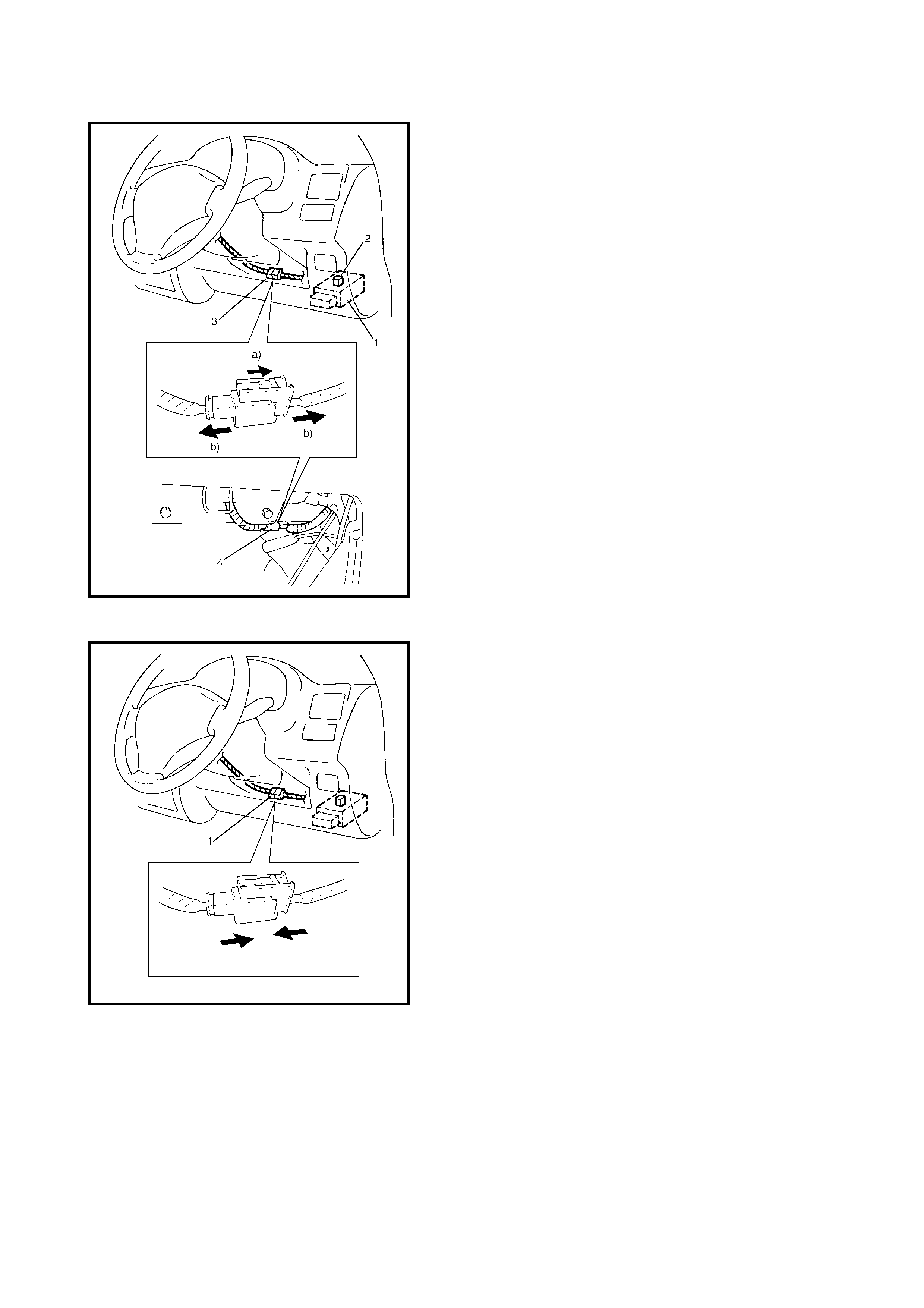
DISABLING AIRBAG SYSTEM
1. Turn steering wheel so that front wheels are pointing
straight-ahead.
2. Turn ignition switch to LOCK position and remove key.
3. Remove the airbag fuse (2) from the fuse box (1).
4. Disc onnect the Yellow con nector (3) of the co ntact coil
and combination switch assembly.
a. Release the lock slider.
b. After unlocked, disconnect the connector.
5. Pull-out the glove box while pushing its stopper from
both right and left sides and disconnect the Yellow
connector (4) of the passenger airbag (inflator) module.
a. Release the lock slider.
b. After unlocked, disconnect the connector.
NOTE: With the airbag fuse removed and ignition switch
ON, the airbag warning lamp will be ON.
This is normal operation and does not indicate a airbag
system malfunction.
ENABLING AIRBAG SYSTEM
1. Turn ignition switch to LOCK position and remove key.
2. Connect the Yellow connector (1) of the contact coil
and combination switch assembly by pushing the
connector until a click is heard.
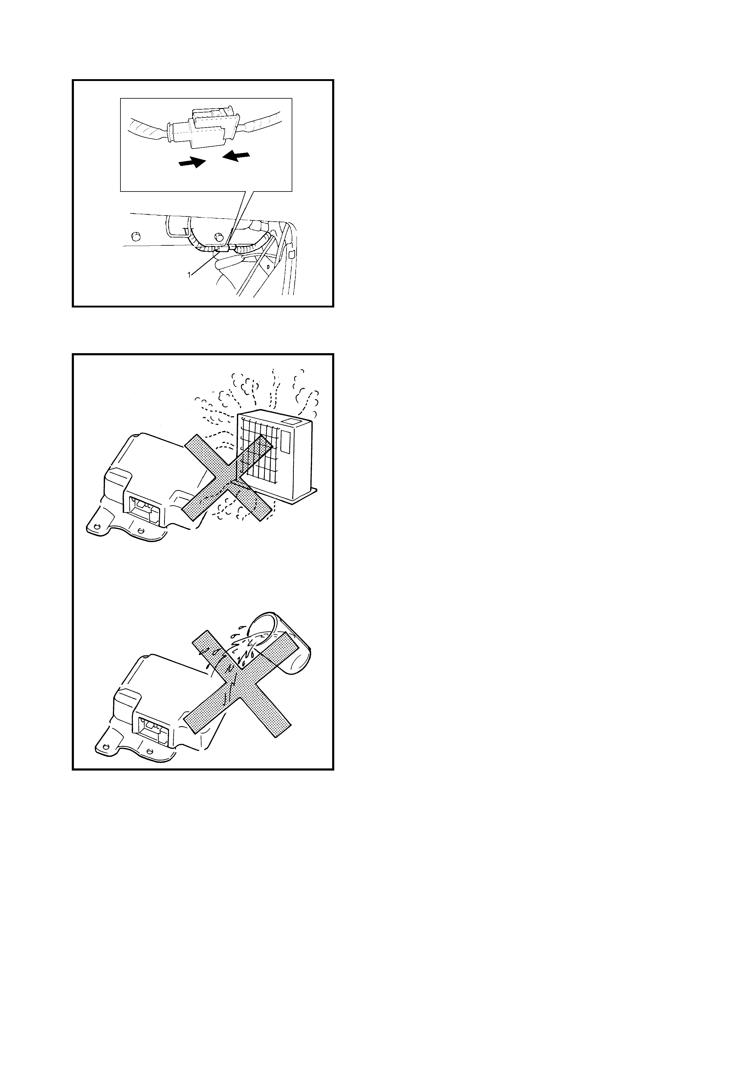
3. Connec t the passen ger airba g (inflator ) module Yellow
connector (1) by pushing until a click is heard.
4. Install the glove box.
5. Install the airbag fuse into the fuse box.
6. Turn ignition switch to ON position and verify that the
AIRBAG warning lamp flashes 6 times and then turns
OFF.
If it does not operate as described, perform
2.4 AIRBAG DIAGNOSTIC SYSTEM CHECK.
HANDLING AND STORAGE
SDM
WARNING:
Never power up the airbag system when
the SDM is not rigidly attached to the vehicle. Other-
wise, personal injury may resul t.
CAUTION:
After detecting one collision that meets
deployment conditions, the SDM must not be used.
Refer to 2.4 AIRBAG DIAGNOSTIC SYSTEM CHECK
when checking the SDM.
• Never attempt disassembly of the SDM.
• When storing the SDM, select a place where neither
high temperature nor high humidity is anticipated and
oil, water and dust are kept off.
• If the SDM has been dropped, replace it with a new
one.
• If the installation part of SDM was damaged, repair that
part completely before reinstallation.
• All SDM and mounting bracket fasteners must be care-
fully torque d and the arr ow mu st b e pointe d towa rd the
front of the vehicle to ensure proper operation of the
airbag system.
Live (undeployed) Airbag (inflator) Modules
Special care is nec essa ry when handli ng an d stor ing a l ive
(undeployed) airbag (inflator) module.
The rapid gas generation produced during deployment of
the airbag could cause the airbag (inflator) module, or an
object in front of the airbag (inflator) module to be thrown
through the air, in the unlikely event of an accidental
deployment.
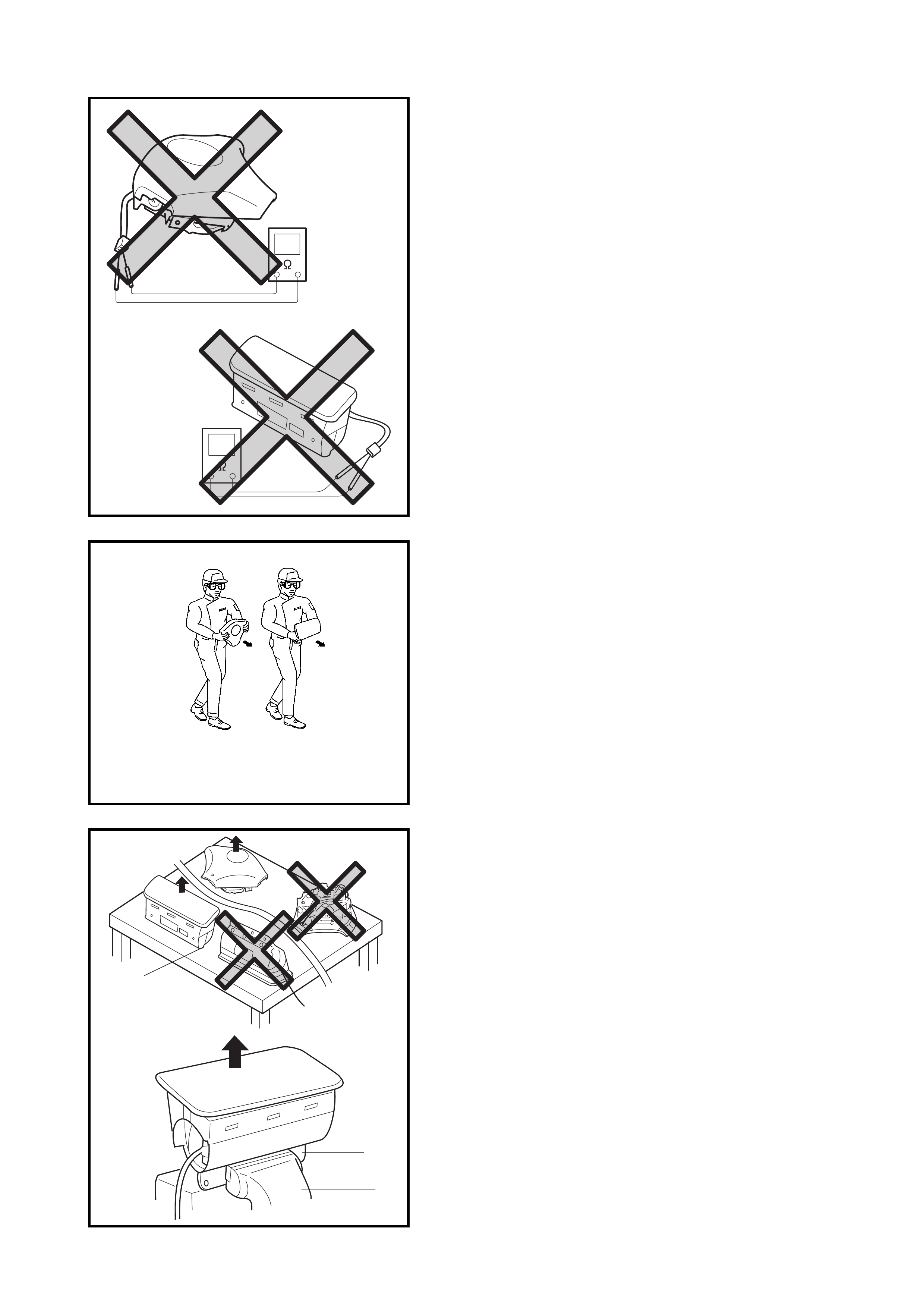
WARNING:
Never attempt to measure the resistance
of the airbag (inflator) modules as the electric cur-
rent from the tester may deploy the airbag.
• Never attempt disassembly of the airbag (inflator) mod-
ules.
• If any ab normality is found, re place it wi th new one as
an assembly.
• When an abnormality is noted as existing in a live
(undeployed) airbag (inflator) module, deploy it before
discarding it.
• If grease, cleaning agent, oil, water, etc., gets on an
airbag (inflator) module, wipe it off immediately with a
dry cloth.
• If an airbag (inflator) module is dropped from a height
of 90 cm or more, it should be replaced with a new one
as an assembly.
WARNING:
•For handling and storage of a live airbag (inflator)
module, select a pla ce w her e th e ambie nt temp e ra-
ture is below 65°C, without high humidity and away
from electric noise.
• When carrying a live airbag (inflator) module, make
sure the bag opening is pointed away from you. In
case of an accident al deployment, the bag will then
deploy with minimal chance of injury. Never carry
the airba g ( inflator) module by t he wire s or conne c-
tor on the underside of the module, otherwise, per-
sonal injury may result.
WARNING: When placing a live airbag (inflator) module
on a bench or other surface, always face the airbag up,
away f rom the surface. P lace it on a wo rkbench with a
slit (1) or use the workbench vise (2) to hold it securely
at its lower mounting bracket (3).
It is also prohibited to place anything on top of the trim
cover or stack airbag (inflator) modules.
Free space must be provided to allow the airbag to
expand in the unl ikely event of acciden tal deployment ,
otherwise, personal injury may result.
1
2
3
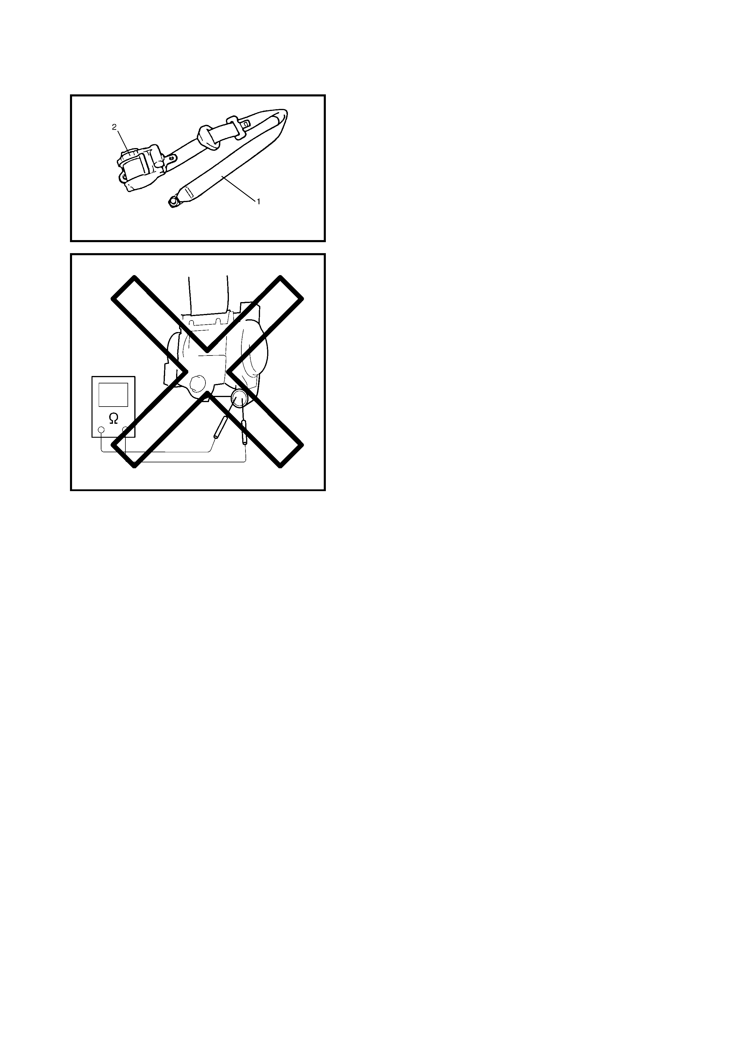
Live (inacti vated) Seat Belt Pretensioner
Special care is nec essa ry when handli ng an d stor ing a l ive
(inactivated) seat belt pretensioner.
When the seat belt pretensioners activate, gas is gener-
ated and the seat belt (1) is retracted into the retractor
assembly (2) quickly.
Note, therefore, that if they activate accidentally, the seat
belt pre tens ioner s and othe r obj ect(s ) ar oun d th em m ay be
thrown through the air.
WARNING:
Never attempt to measure the resistance
of th e s eat b el t pret en sion ers as the el ectric cu rre nt
from the tester may activate pretensioner.
• Never attempt to disassemble the seat belt pretension-
ers (retractor assembly).
• If any ab normality is found, re place it wi th new one as
an assembly.
• When an abnormality is noted as existing in the live
(inactivated) seat belt pretensioner, activate it before
discarding it.
• If grease, cleaning agent oil, water, etc., gets on the
seat belt pre tensioners (retr actor asse mbly), wipe it off
immediately with a dry cloth.
• If a seat belt pretensioner is dropped it should be
replaced with a new one as an assembly.
WARNING:
•For handling and storage of a live seat belt preten-
sioner, select a place where the ambient tempera-
ture is below 65°C (150°F), without high humidity
and away from electric noise.
• Never carry the seat belt pretensioner by the wire
or connector of the pretensioner.
• When placing a live seat belt pretensioner on the
workbench or other surface, do not put anything
on it otherwise, personal injury may result.
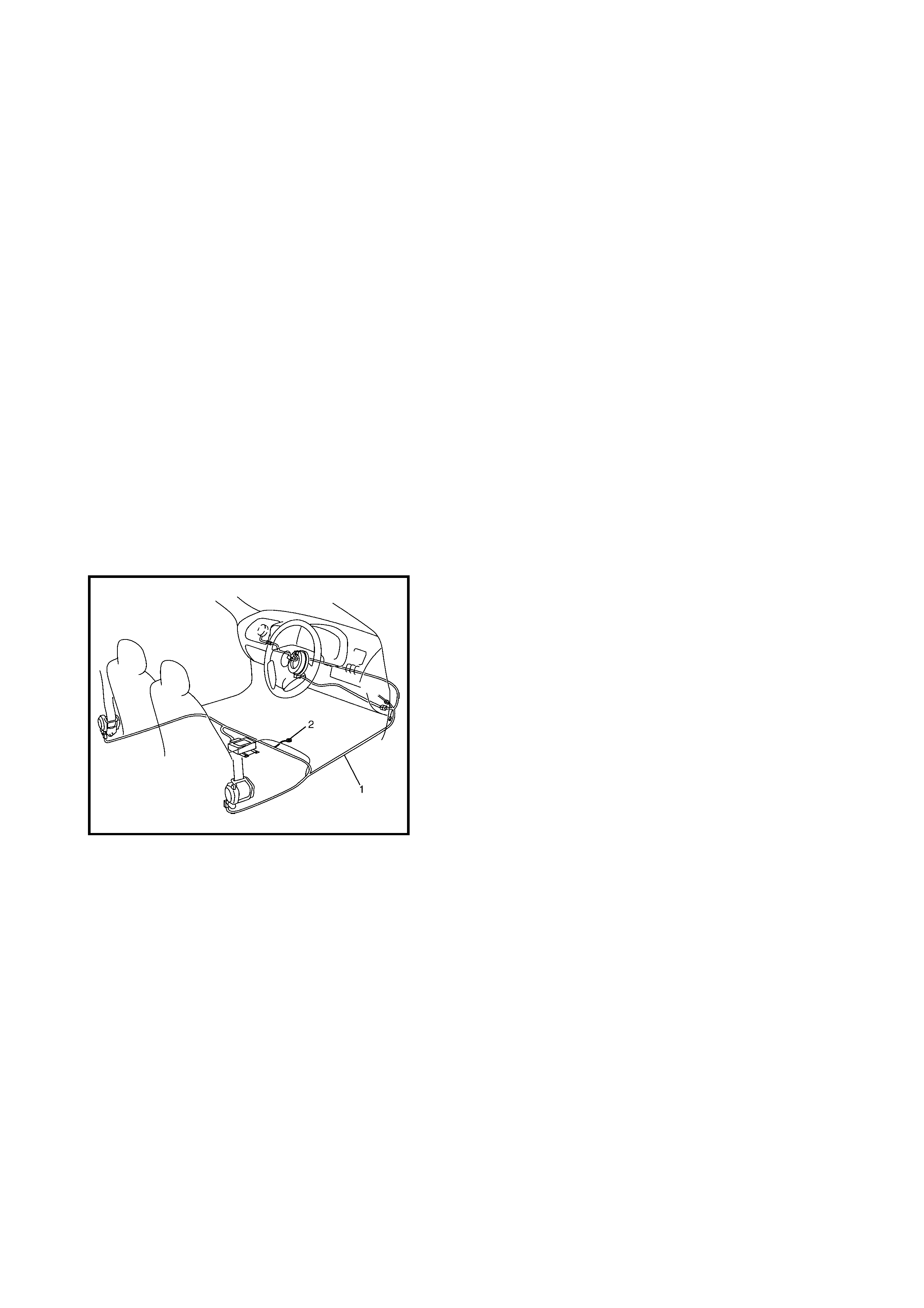
Deployed Airbag (inflator) Module and Activated
Seat Belt Pretensioner
WARNING:
• The airbag (inflator) module and seat belt preten-
sioner is very hot immediately after deployment/
activation. Wait for at least 30 minutes for it to cool
before proceeding any work.
• Do not apply water, oil, etc. to a deployed airbag
(inflator) module or an activated seat belt preten-
sioner.
• After an airbag (inflator) module has been
deployed, the surface of the airbag may contain a
powdery residue. This powder consists primarily
of cornstarch (used to lubricate the bag as it
inflates) and by-produc ts of the chemical reaction.
As with many service procedures, gloves and
safety glasses should be worn.
• Wash your hands with mild soap and water after
completing the work.
Refer to 4.3 DEPLOYED AIRBAG (INFLATOR) MODULE
AND ACTIVATED SEAT BELT PRETENSIONER
DISPOSAL in this Section.
Airbag Wire Harness and Co nnector
The airbag wire harness is included in the floor wire har-
ness ( 1) a nd can be id entifie d eas ily as it is cov ered w ith a
yellow protection tu be and has yellow con nectors. Be very
careful when handling it.
• When an open in the airbag wire harness, damaged
wire harness, connector or terminal is found, replace
the wire harness, connectors and terminals as an
assembly.
• When installing it, take care that the airbag wire har-
ness is not caught or does not interfere with other
parts.
• Make sure all airbag system grounding points (2) are
clean and grounds are securely fastened for optimum
metal-to-metal contact. Poor grounding can cause
intermittent problems that are difficult to diagnose.

Disposal
Do not dispose of a live (undeployed) airbag (inflator) mod-
ule a live (inactivated) seat belt pretensioner. When dis-
posal is necessary, deploy/deactivate the airbag or seat
belt pretensioner according to deployment/activation pro-
cedure described in 4. AIRBAG (INFLATOR) MODULE
AND SEAT BELT PRETENSIONER DISPOSAL in this
Section.
WARNING: Failure to follow proper airbag (inflator)
module and seat belt pretensioner disposal proce-
dures can result in airbag deployment and preten-
sioner activation which could cause personal injury.
An undeployed airbag (inflator) module or inactivated
seat belt pret ensioner must not be disposed of thro ugh
normal refuse channels.
The undeployed airbag (inflator) module or inactivated
seat belt pretensioner contain substances that can
cause severe illness or personal injury if the sealed
container is damaged during disposal.
3.2 REPAIRS AND INSPECTIONS REQUIRED AFTER A COLLISION
CAUTION:
• All airbag system components, including the electrical harness and component mounting points,
must be inspected after an accident. If any components are damaged or bent they must be
replaced, even if airbag system activation did not occur.
• Never use airbag system parts from another vehicle.
• Do not attempt to service the following parts, service of these parts is by replacement only:
•Driver/P ass eng er air bag (infla tor) modul e,
•Driver/Passenger seat belt pretensioner,
•SDM,
•Contact coil and combination switch assembly,
•Airbag wire harness.
• Proper operation of the airbag system requires that any repairs to the vehicle structure return it to
its original production configuration.
• After detecting one collision that meets deployment conditions, the SDM must not be used. Refer
to 2.4 AIRBAG DIAGNOSTIC SYSTEM CHECK in this Section when checking the SDM.
COLLISION WITH DEPLOYMENT / ACTIVATION –
COMPONENT REPLACEMENT
The following components must be replaced.
• Driver and passenger airbag (inflator) modules
• Driver and passenger seat belt pretensioners
•SDM.
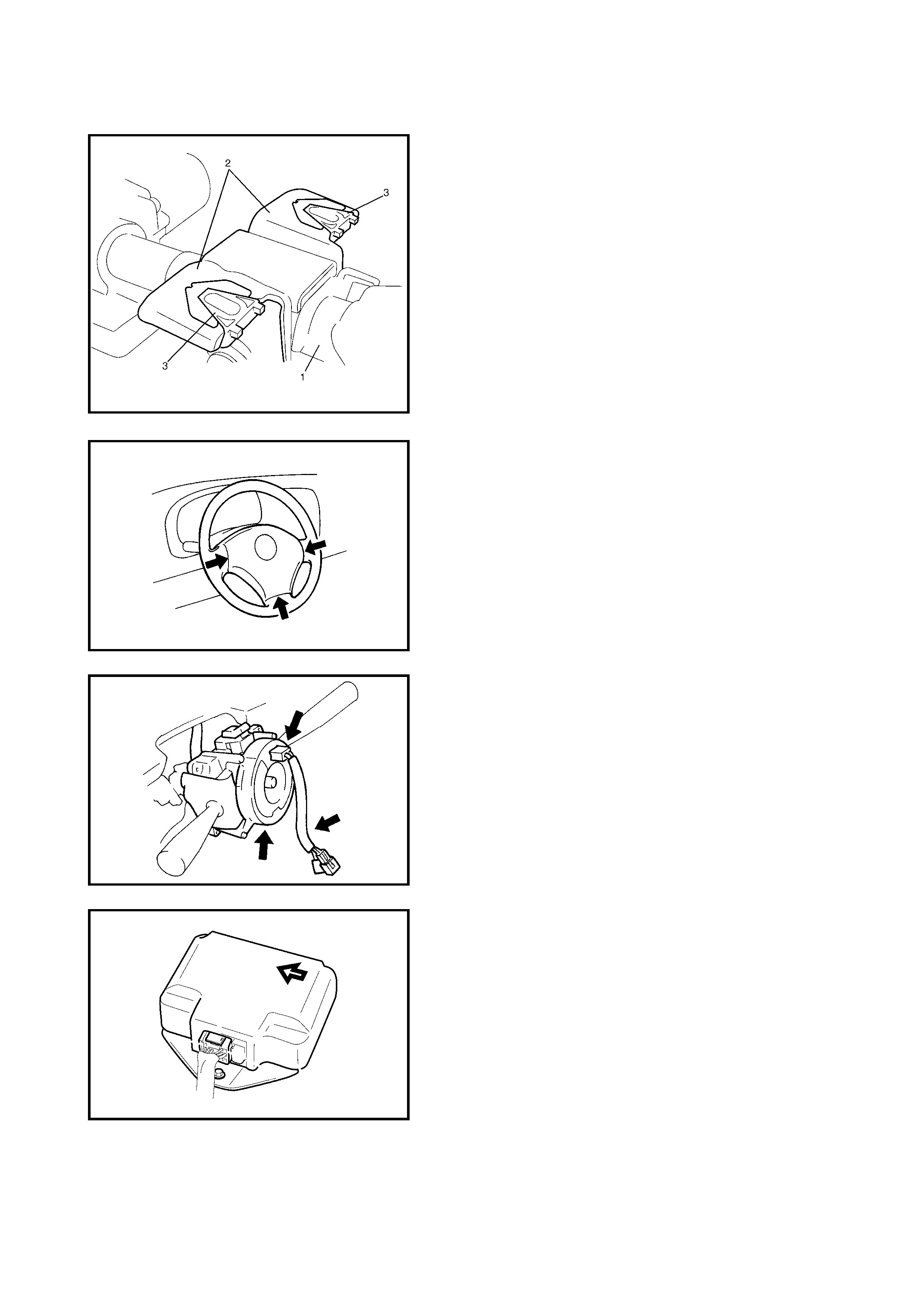
COLLISION WITH OR WITHOUT DEPLOYMENT /
ACTIVATION – COMPONENT INSPECTIONS
Certain airbag system components must be inspected after
any crash, whether the airbag system has activated or not.
Those components are :
• Steering column (1) and shaft joints:
•Check for length, damage and bend, refer to
3.9 CHECKING STEE RING COLUMN ASSEMBLY
AND LOWER SHAFT FOR ACCIDENT DAMAGE
in Section 3C.
If any faulty condition is found in above checks, replace
faulty part.
• Steering column bracket (2) and capsules (3)
•Check for damage and if it is bent.
If any faulty condition is found in above checks, replace
faulty part.
• Steering wheel and driver airbag (inflator) module:
•Check for damage or airbag (inflator) module fit.
•Check trim cover (pad surface) for cracks.
•Check wire harness and connector for damage or
tightness.
If any faulty condition is found in above checks, replace
faulty part.
• Contact coil and combination switch assembly
•Check wire harness and connectors for damage or
tightness.
•Check contact coil case for damage.
If any faulty condition is found in above checks, replace.
• SDM and SDM plate:
•Check for external damage such as deformation,
scratch, crack, peeled paint, etc.
•Check that the SDM can be installed properly and is
not damaged (there is a gap between SDM and
SDM plate, or it cannot be fixed securely).
•Check that the connector or lead wire of the SDM for
scorching, melting or damage.
•Check that the connector is connected securely or
locked.
•Check the SDM connector and terminals for tightness.
•Check that the SDM sets a diagnostic trouble code
(Refer to 2.6 DTC CHECK) and the diagnostic table
leads to a malfunctioning SDM.
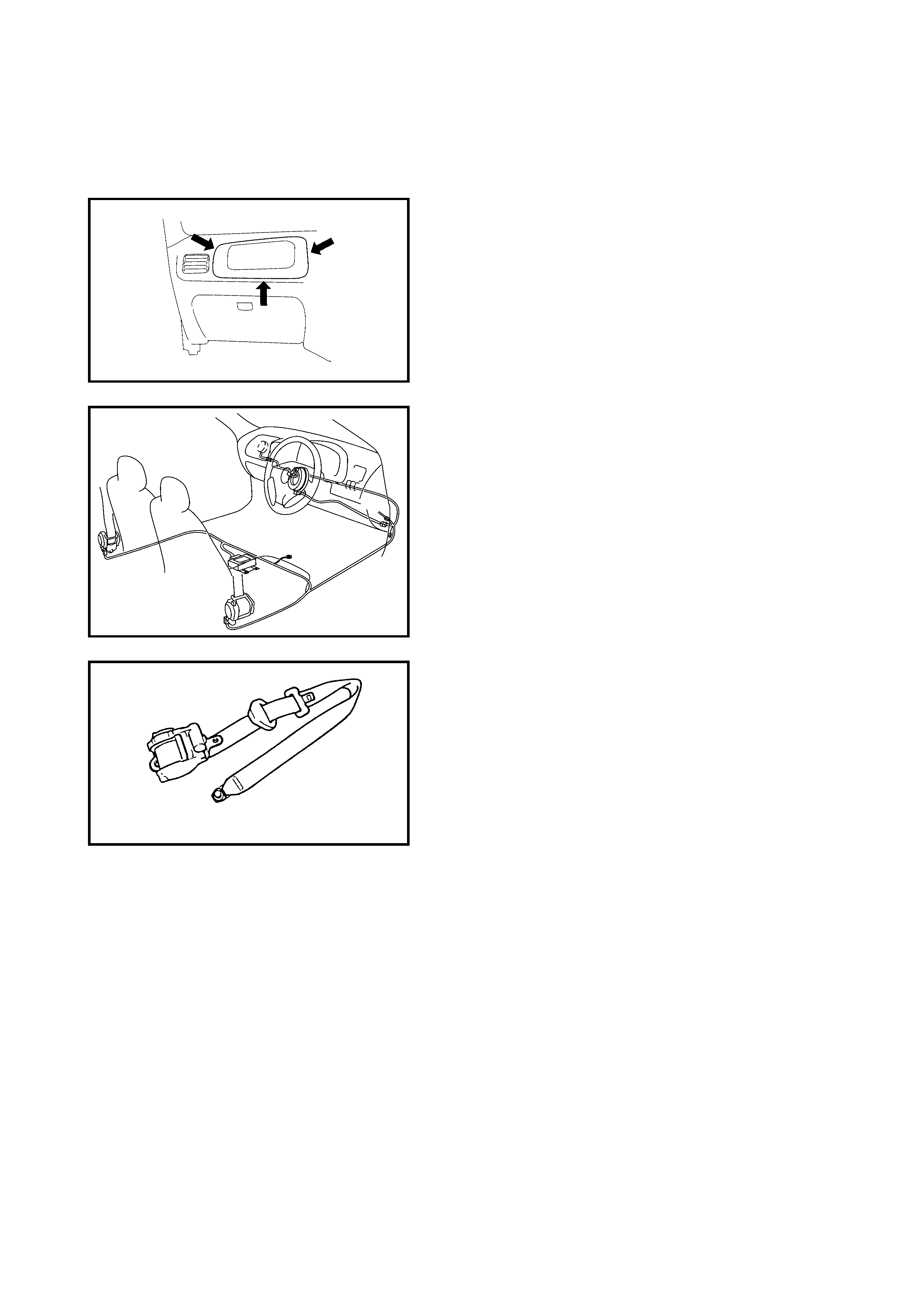
If any faulty condition is found in above checks, replace.
• Instrument panel member and reinforcement:
•Check for any distortion, bending, cracking or other
damage.
If any faulty condition is found in above checks, replace.
• Passenger airbag (inflator) module:
•Check for dents, cracks, damage or fit.
•Check trim cover for cracks or deformities.
•Check harness and connector for damage or tight-
ness.
If any faulty condition is found in above checks, replace.
• Airbag wire harness and connections:
•Check for damage, deformity or poor connections,
refer to 2.3 INTERMITTENTS AND POOR
CONNECTIONS in this Section.
•Check wire harness clamps for tightness.
If any faulty condition is found, correct or replace.
• Seat belt pretensioner:
•Check for dents, cracks, damage or fit.
•Check harness and connector for damage or tight-
ness.
If any faulty condition is found in above checks, replace.
• Seat belts and mounting points:
•Refer to 3.2 FRONT SEAT BELT ASSEMBLY in
Section 10 in this Section.
• Airbag warning lamp
•After vehicle is completely repaired, perform
2.4 AIRBAG DIAGNOSTIC SYSTEM CHECK.
3.3 SDM
WARNING: During service procedures, be very careful
when handling a Sensing and Diagnostic Module
(SDM).
Be sure to read SERVICE PRECAUTIONS before start-
ing to work and observe every precaution during work.
Neglecting them may result in personal injury or inacti-
vation of the airbag system when necessary.
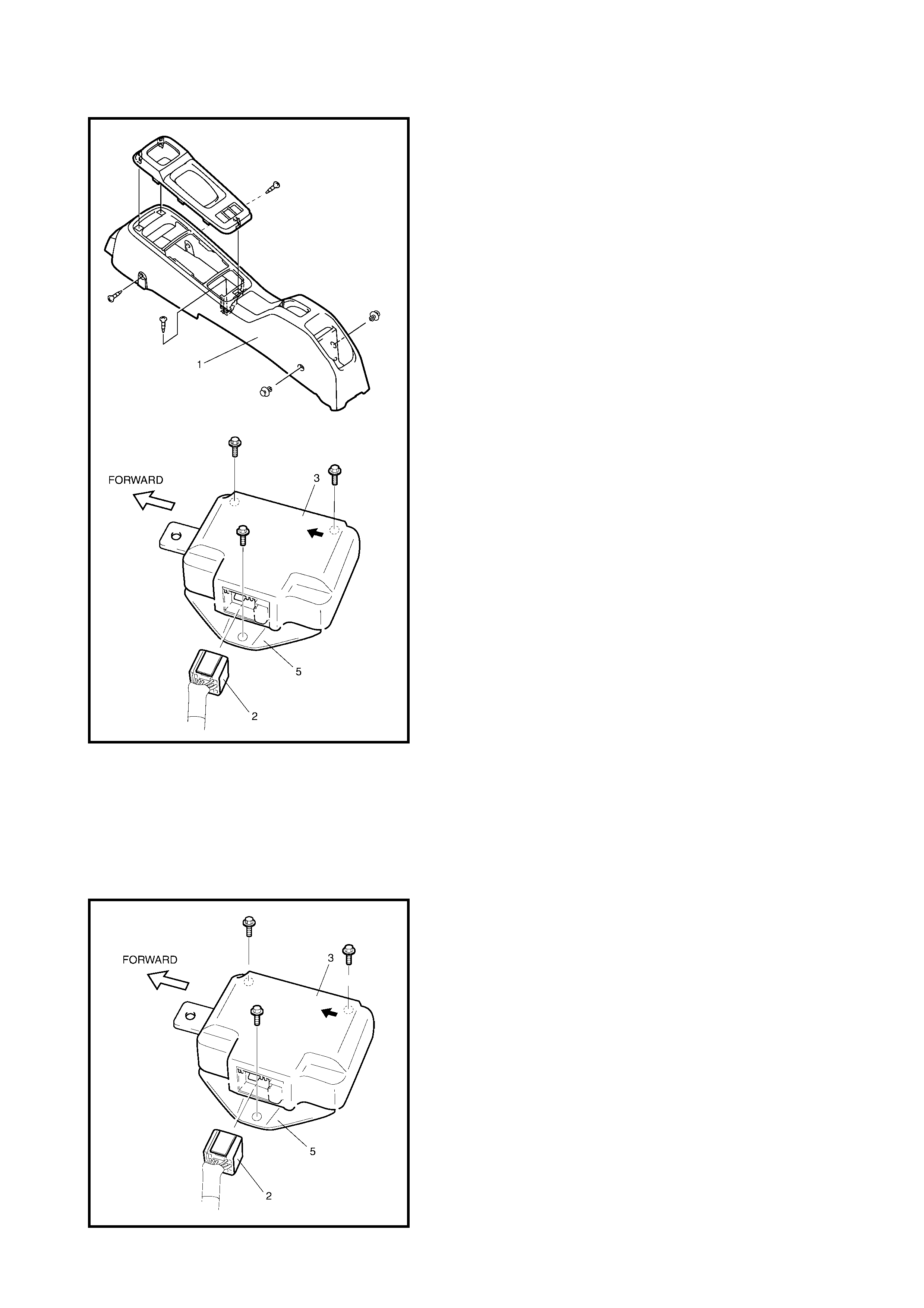
REMOVAL
1. Disconnect negative cable at battery.
2. Disable the airbag system, refer to 3.1 SERVICE
PRECAUTIONS in this Section.
3. Remove th e ce ntre co nsole box es (1) by rem oving th e
screws and clips.
4. Disconnect the SDM connector (2) from the SDM (3).
5. Remove the SDM (3) with the SDM plate (5) as an
assembly
CAUTION:
Do not separate the SDM (3) and SDM
plat e (5).
INSPECTION
CAUTION:
• Do not connect a tester, whatever type it may be.
• Never repair or disassemble the SDM (3).
• If the SDM has been dropped, or if there are cracks,
dents or other defects in the case or plate, replace it
with a new one.
• Check the SDM (3) and SDM plate (5) for dents, cracks
or deformation.
• Check the S DM connect or (2) for damage, crack s and
the lock mechanism.
• Check SDM terminal for bend, corrosion or rust.
If any faulty condition is found in above checks, replace.
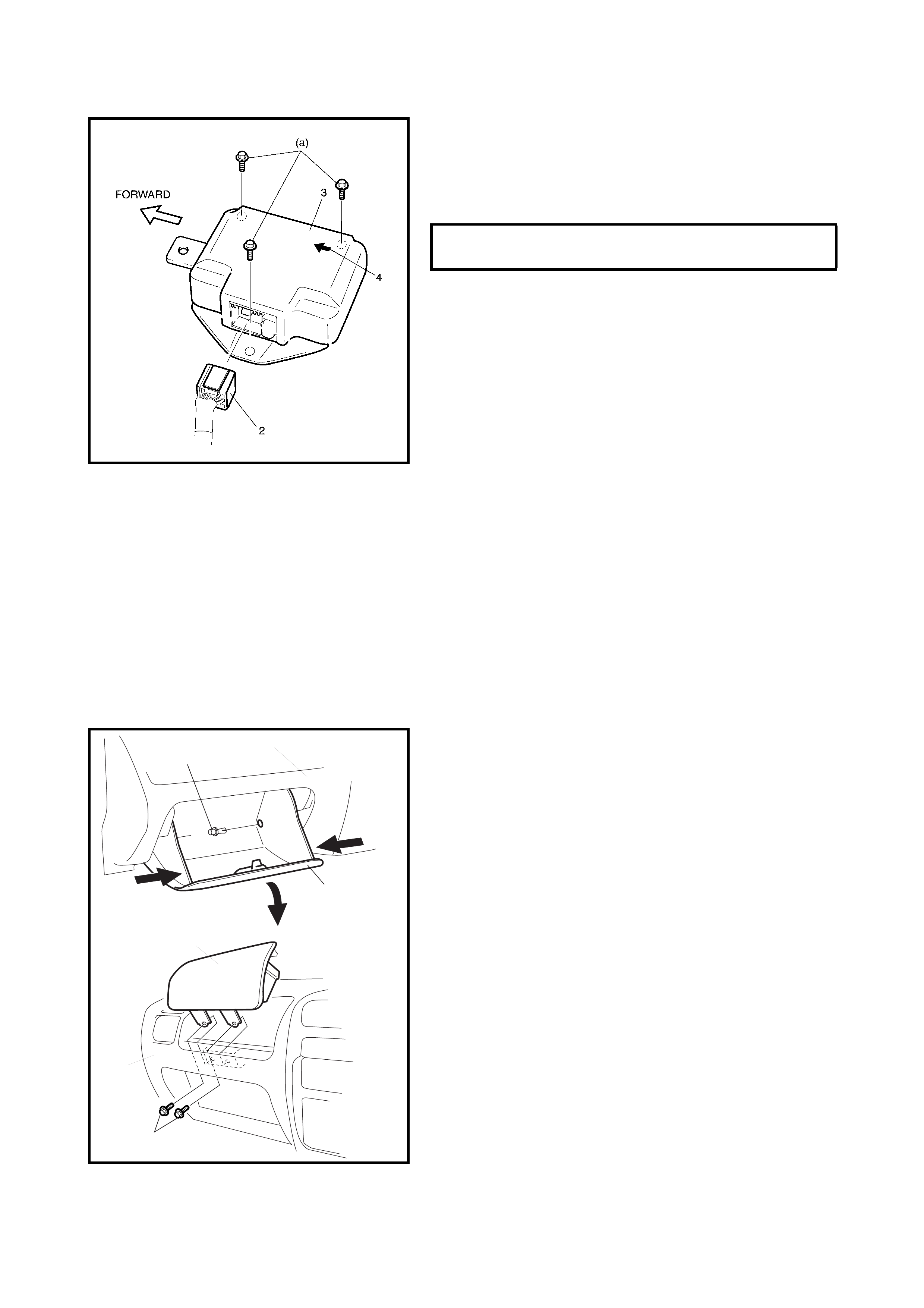
INSTALLATION
For installation, reverse removal procedure, noting the fol-
lowing point s:
• Ensure that the arrow (4) on the SDM (3) is pointing
toward the front of the vehicle.
• Tighten the SDM bolts to specified torque.
• Connect the SDM connector (2) to the SDM (3)
securely.
• Enable the airbag system. Refer to 3.1 SERVICE
PRECAUTIONS in this Section.
3.4 PASS EN GER AIRBAG (INFLATOR) MODULE
WARNING:
• Never attempt to disassemble or repair the passen-
ger airbag (inflator) module. If any abnormality is
found, replace it with new one as an assembly.
• Read 3.1 SERVICE PRECAUTIONS in this Section
before s tarting wo rk and ob serve every p recaution
during work. Neglecting them may result in per-
sonal injury or undeployment of the airbag when
necessary.
REMOVAL
1. Disconnect negative cable at battery.
2. Open the glove box (1).
3. While pressing the glove box stopper, pull out the glove
box (1) from the in strumen t panel ( 4) and the n remov e
the glove box clip (2) and glove box (1) from the instru-
ment panel (4) .
4. Disable the airbag system, refer to 3.1 SERVICE
PRECAUTIONS in this Section.
5. Remove the passenger airbag (inflator) module (3)
attaching bolts (5) and the passenger airbag (inflator)
module (3).
SDM MOUNTING BOLT TORQUE
SPECIFICAT ION (a) 6.0 Nm
1
24
Push
Pull
Push
3
4
5
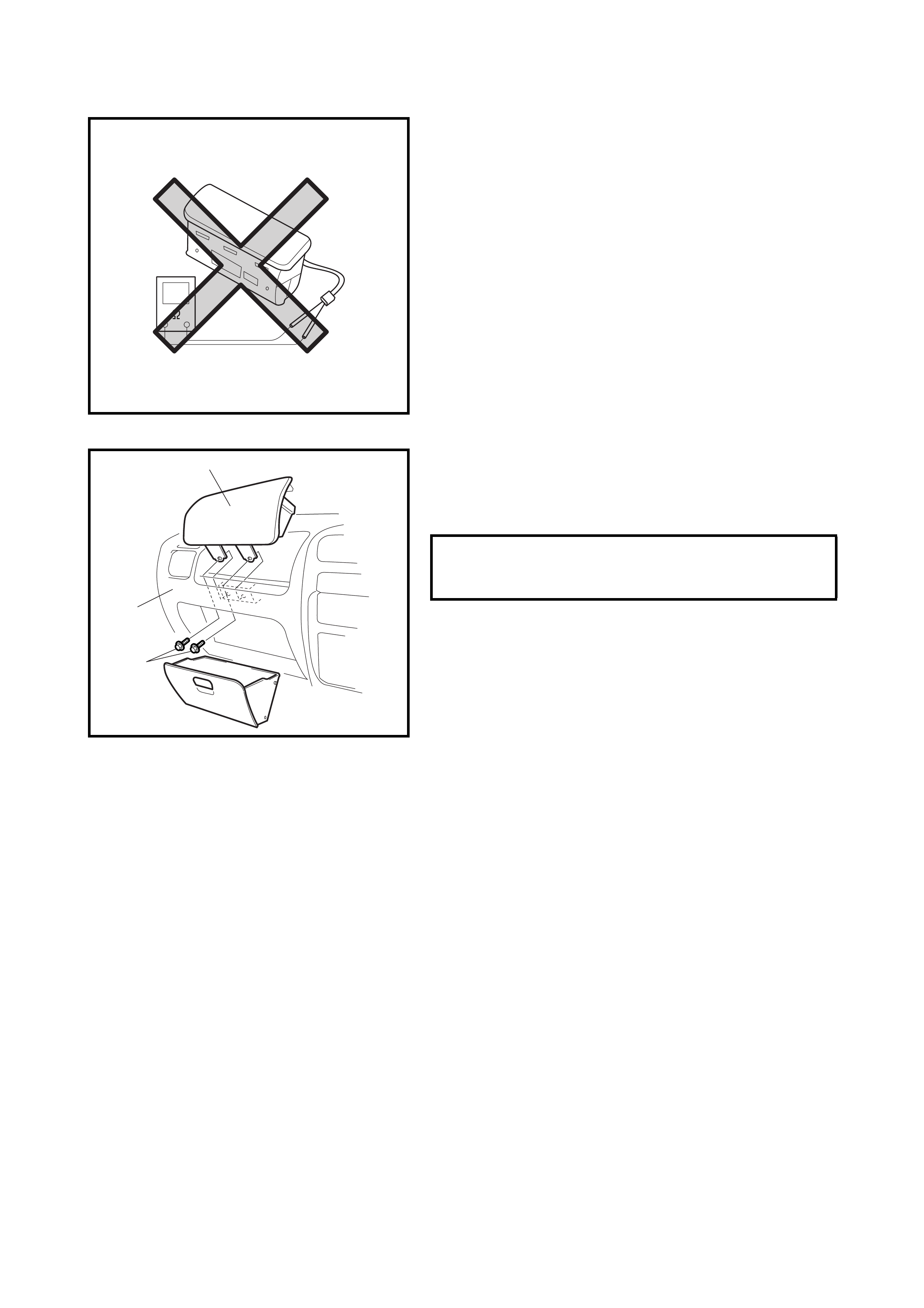
INSPECTION
WARNING:
Never measure the resistance of passen-
ger a irb ag ( inf l ato r ) mo du l e or di sas sembl e i t as per -
sonal injury may result.
CAUTION:
If an airbag (Inflator) module is dropped
from a height or 90 cm or more, it should be
replaced.
Check the airbag (inflator) module appearance visually for
following symptoms and if any one of them is applicable,
replace with a new one.
• Airbag has deployed.
• There is a crack in the trim cover (pad surface).
• Wire harness or connector is damaged.
• Airbag (inf lator ) module is damaged or a strong im pact
was applied to it.
INSTALLATION
1. Install th e passen ger airba g (in flator) modul e (1) to the
instrum ent panel (2) .
2. Tighten the passenger airbag (inflator) module
attaching bolts to the specified torque.
3. Connect the negative cable to the battery.
4. Enable the airbag system, refer to 3.1 SE RVICE
PRECAUTIONS in this Section.
3.5 DRIVER AIRBAG (INFLATOR) MODULE
Refer to 3.2 DRIVER AIRBAG (INFLATOR) MODULE in
Section 3C for removal, inspection and installation.
3.6 CONTACT COIL AND COMBINATION SWITCH ASSEMBLY
Refer to 3.5 CONTACT COIL AND COMBINATION
SWITCH ASSEMBLY in Section 3C for removal, inspection
and installation.
3.7 SEAT BELT PRETENSIONER
Refer to 3.2 FRONT SEAT BELT ASSEMBLY in Section 10
for removal, inspection and installation.
PASSENGER AIRBAG (INFLATOR)
MODULE MOUNTING BOLT
TORQUE SPECIFICATION (a)
23.0 Nm
1
2
(a)
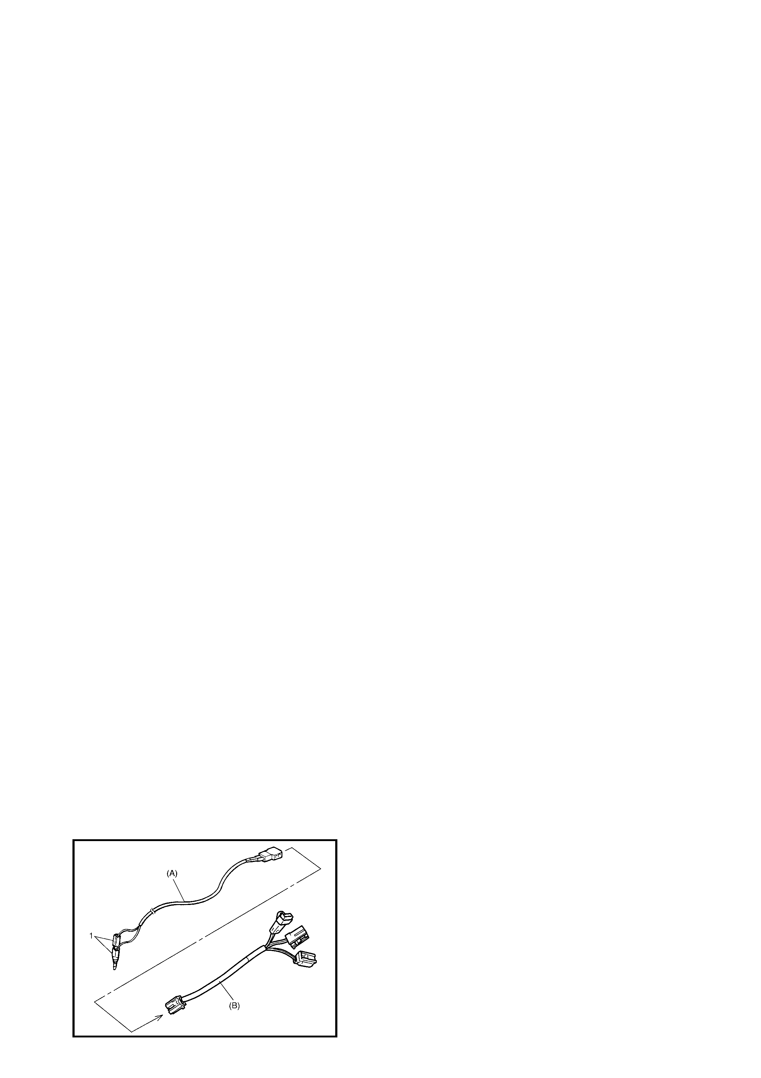
4. AIRBAG (INFLATOR) MODULE AND
SEAT BELT PRETENSIONER DISPOSAL
WARNING: Failure to follow proper airbag (inflator) module and seat belt pretensioner disposal proce-
dures can result in airbag deployment and pretensioner activation, which may cause personal injury.
Do not dispose of a live (undeployed) airbag (inflator) module and seat belt pretensione r.
An undeployed airbag (inflator) module / inactivated seat belt pretensioner must not be disposed of
through normal refuse channels. The undeployed airbag (inflator) module and inactivated seat belt
pretensioner contain substances that can cause severe illness or personal injury if the sealed con-
tainer is damaged during disposal.
An airbag (inflator) module or seat belt pretensioner can be deployed / activated inside or outside the vehicle.
The deployment / activation method used depends upon the final disposition of the vehicle. Review the follow-
ing instructions to determine which is best in a given situation.
Deployment / Activation Outside Vehicle:
When i t is intend ed to ret urn th e veh icle to serv ice, de ploy the ai rbag (i nflator) modu le(s) or acti vate the se at
belt pretensioner(s) outside the vehicle.
Deployment / Activation Inside Vehicle:
When the vehicle is to be destroyed, salvaged for component parts, deploy the airbag modules and/or acti-
vate the seat belt pretensioners installed in the vehicle.
WARNING: The follo wi ng pr ecaut ion s must be o bse rve d fo r th is wor k. F a ilure t o o bser ve a n y of th em
may result in personal injury.
• The procedure should be followed strictly as described here.
•Read 3.1 SERVICE PRECAUTIONS beforehand.
• To avoid accidental deployment, this work should be performed by no more than one person.
• Since smoke is produced when an airbag (inflator) module is deployed or a pretensioner is
activated, select a well-ventilated area.
• An airbag (inflator) module and seat belt pretensioner will immediately deploy / activate when a
12 volt power supply is connected to it. Wear safety glasses throughout this entire deployment /
activation and disposal procedure.
• Wear suitable ear protection when deploying an airbag or activating a pretensioner. Also, advise
those who are in the area close by to also wear suitable ear protection.
• Do not deploy or activate two or more airbag (inflator) modules or seat belt pretensioners at the
same time.
• Never connect a deployment harness to any 12 volt power source before connecting the deploy-
ment harness to the airbag (inflator) module and seat belt pretensioner. The deployment harness
shall remain shorted and not be connected to the 12 volt power source until the airbag or the pre-
tensioner is ready to be deployed or activated.
4.1 DEPLOYMENT / ACTIVATION OUTSIDE VEHICLE
When it is intended to return the vehicle to service,
deploy the airbag (inflator) module(s) or activate the
seat belt pretensioners(s) outside of t he vehicle.
1. Turn ignition switch to LOCK and remove the key.
2. Wear safety glasses during this deployment / activation
procedure.
3. Check that there is no open, short or damage in special
tools (A) 09932-75030 deployment harness and (B)
09932-78331 adaptor cable. If any fault is found, do
not use it.
NOTE: If a faulty seat belt pretensioner connector of the
adapter cable is found, replace it with a spare connector.
4. Short (1) the two deployment harness leads together
by fully seating one banana plug into the other.
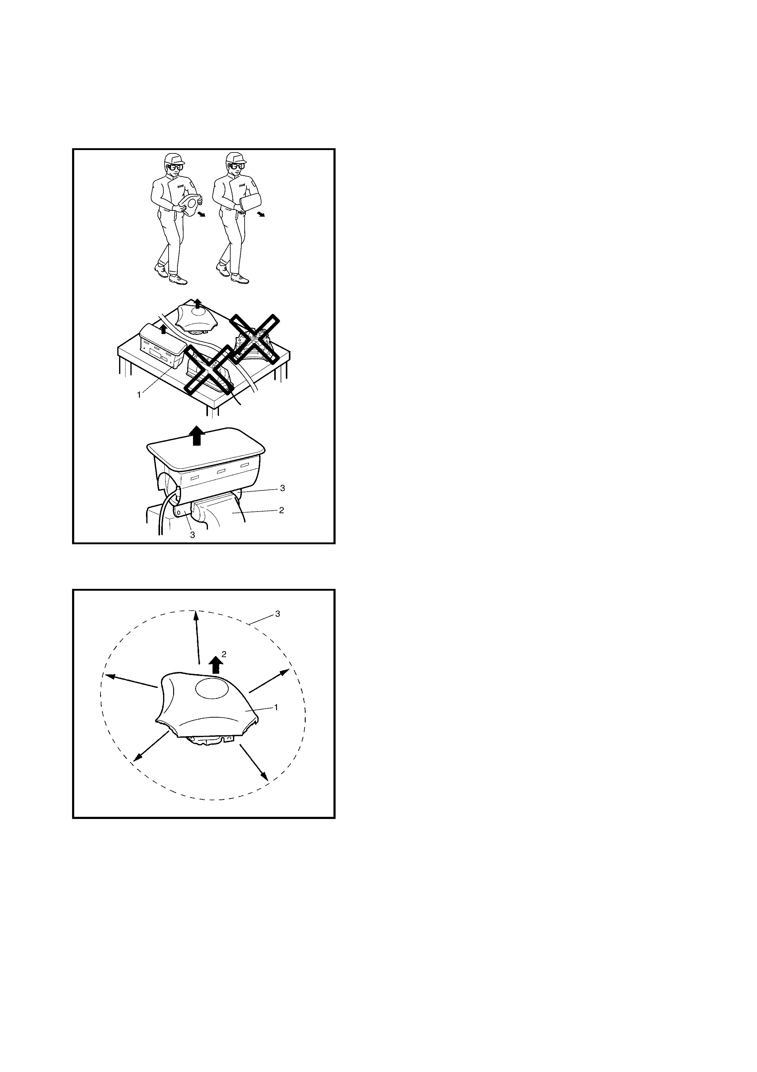
WARNING: The d
eployment harness shall remain
shorted and not be connected to a 12 volt power
source until the airbag is ready to be deployed and
seat belt pretensioner is ready to be activated.
5. Remove airbag (inflator) module(s) and seat belt
pretensioner(s) from vehicle, refer to
Section 3C - 3.2 DRIVER AIRBAG (INFLATOR)
MODULE, Section 10,
3.4 PASSENGER AIRBAG (INFLATOR) MODULE or
3.5 DRIVER AIRBAG (INFLATOR) MODULE in this
section.
WARNING:
•For handing and storage of a live seat belt preten-
sioner, select a place where the ambient tempera-
ture below 65°C, without high humidity and away
from electric noise.
• Never carry the seat belt pretensioner by the wire
or connector of the pretensioner.
• When placing a live seat belt pretensioner on the
workbench or other surface, do not put anything
on it.
Personal injury may result.
6. Set the airbag (inflator) module or seat belt preten-
sioner as fol low s.
• For the driver airbag (inflator) module:
a. Clear a space (3) on the ground about 185 cm in
diameter for the driver airbag (inflator) module (1)
deployme nt. A paved, outdoor locat ion where there
is no activity is preferred. If an outdoor location is
not available, a space on the shop floor where
there is no activity and sufficient ventilation is rec-
ommended.
Ensure no loose or flammable objects are within
the deployment area.
b. Place the dr iver ai rbag ( i nflator ) module (1) , wi th its
vinyl trim cover facing up (2), on the ground in the
cleared space.
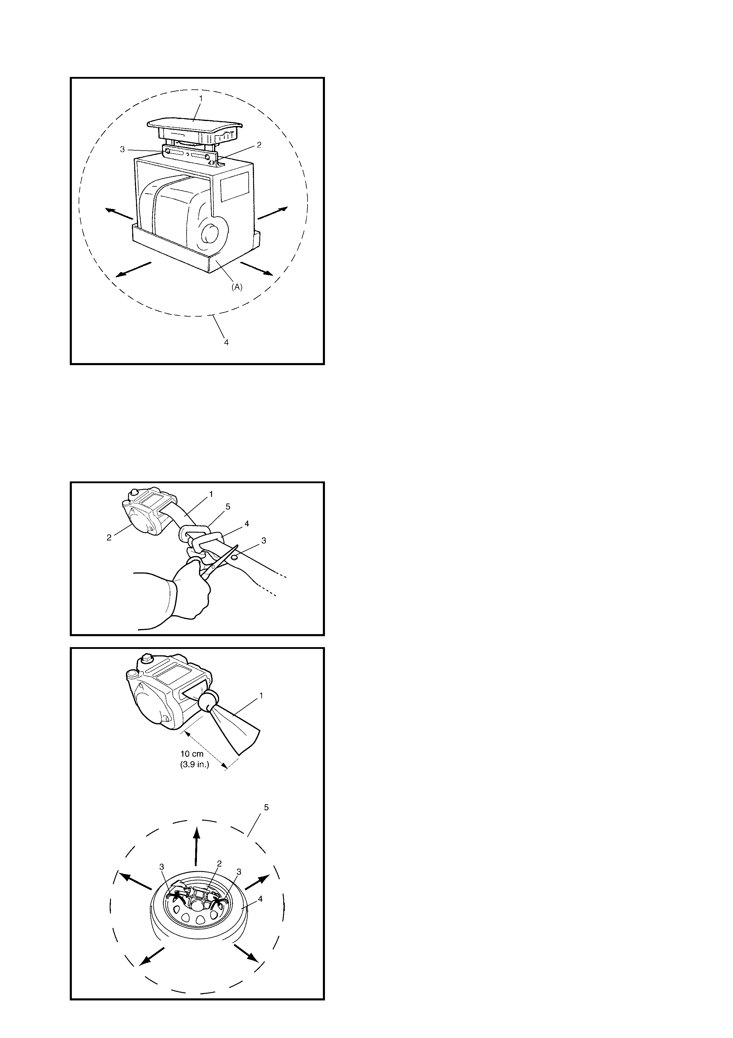
• For the pa ssenger airbag (inflator) module.
a. Clear a space (4) on the ground about 185 cm in
diameter, where the passenger airbag (inflator)
module (1 ) is to be pl aced fo r depl oymen t. A paved
outdoor location where there is no activity is
preferred. If an outdoor location is not available, a
space on the shop floor where there is no activity
and sufficient ventilation is recommended. Ensure
that no loose or flammable objects are within the
deployment area.
b. Place the deployment fixture, special tool (B)
09932-75041, on the ground in the cleared space.
c. Fill the plastic reservoir in the deployment fixture
with water or sand. This is necessary to provide
su fficient stabilisation of the fixture duri ng
deployment.
d. Attach the passeng er ai rbag (in flator ) module (1) in
the fixtur e se cur e ly usin g the moun tin g at tachmen t,
hold-down bolts and nuts (2) and M8 bolts and nuts
(3).
NOTE: Ensure that the deplo ying dir ection face s as show n
against the mounting attachment.
CAUTION: Use a M8 bolt with a strength of 7T and nut
for fixing the passenger airbag (inflator) module to the
mounting attachment.
• For a seat belt pretensioner.
a. Cut the w ebbing (1 ) at th e ton gue p late stoppe r (3)
of the seat belt pretensioner (2) side as shown.
NOTE: Hold the seat belt pretensioner (2) vertically in
the same condition as it is installed, otherwise the web-
bing can’t be pulled out.
b. Remove the tongue plate (4) and shoulder anchor
(5) from the webbing.
c. Tie the webbing (1) tightly, 10cm from the cutting
edge as shown.
d. Tie the seat belt pretensioner (2) with the a length
of wire 1.25 mm diameter or more (3) to the whee l
fitted with a tyre (4) as shown.
NOTE: Wind the wire around at least three times.
e. Clear a space (5) on the ground about 185 cm in
diameter where the seat belt pretensioner (retractor
assembly) (2) is to be activated. A paved, outdoor
location where there is no activity is preferred. If an
outdoor location is not available, a space on the
shop floor where there is no activity and sufficient
ventilati on is recomm ended.
Ensure no loose or flammable objects are within
the activation area.
f. Plac e the whe el and s eat bel t pretens ioner (re trac-
tor assembly) (1) as shown in the figure on the
ground in the space just cleared.
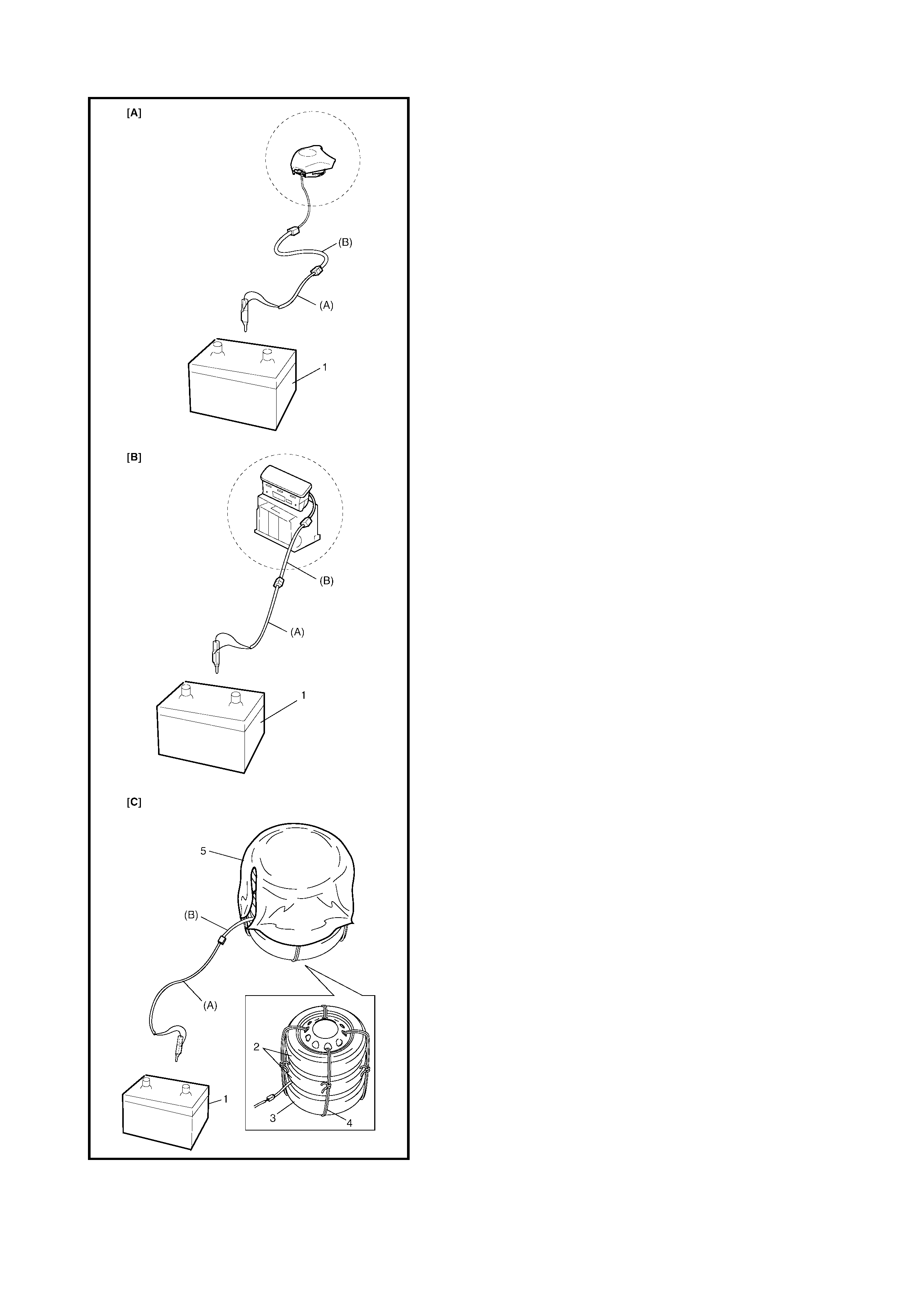
7. Stretch the dep loym ent ha rness (A) 09932-7 5030 from
the airbag (inflator) module or to its full length 10 m.
8. Plac e a 12 v olt power source (1) near the shor ted end
of the deployment harness. A vehicle battery is sug-
gested.
9. Verify that the area ar ound the airbag (in flator) modul e
or seat belt pretensioner is clear of all people and loose
or flammable objects.
10. Connect the adapter cable (B) 09932-78331 as
follows.
a. For the driver airbag (inflator ) modul e [A]:
Verify that the driver airbag (inflator) module is rest-
ing with its vinyl trim cover facing up and connect
the adapter cable (b) to the driver airbag (inflator)
module.
b. For the passenger airbag (inflator) module [B]:
Ver ify tha t the pass eng er airb ag ( in fla tor) mod ul e is
firmly and properly secured in the deployment fix-
ture (special tool) and connect the adapter cable (b)
to the passenger airbag (inflator) module.
c. For a seat belt pretensioner [C]:
Connect the adapter cable (b) to the seat belt pre-
tensioner.
11. Connect the adapter cable (b) to the deployment
harness (A) connector and lock the connectors with the
lock slider.
12. For the seat belt pretensioner:
a. Stack two wheels fitted with tyres (2) on top of the
wheel with the seat belt pretensioner (3) and tie
them with wire 1.25 mm diameter or more (4) as
shown.
NOTE: Wind the wire around at least three times.
b. Drape a blanket (5) over the wheels.
13. Notify a ll people in the im mediate area that y ou intend
to deploy / activa te the airbag (inflator) mo dule or se at
belt pretensioner.
NOTE:
• When the airbag (initiator) module deploys and the pre-
tensioner activ ate s, the rap id gas expansio n wil l crea te
a substantial noise. Wear suitable ear protection. Notify
all people in the immediate area that you intend to
deploy the a irbag (inflator) module or activate th e seat
belt pretensioner and that suitable ear protection
should be worn.
• When the driver airbag (initiator) module deploys it
may jump about 30 cm vertically. This is a normal reac-
tion to the force of the rapid gas expansion inside the
airbag (initiator) module.
• After the airbag (inflator) module has been deployed,
the surface of the airbag may contain a powdery resi-
due. This powder consists primarily of cornstarch (used
to lubricate the bag as it inflates) and by-products of
the chemical reaction.
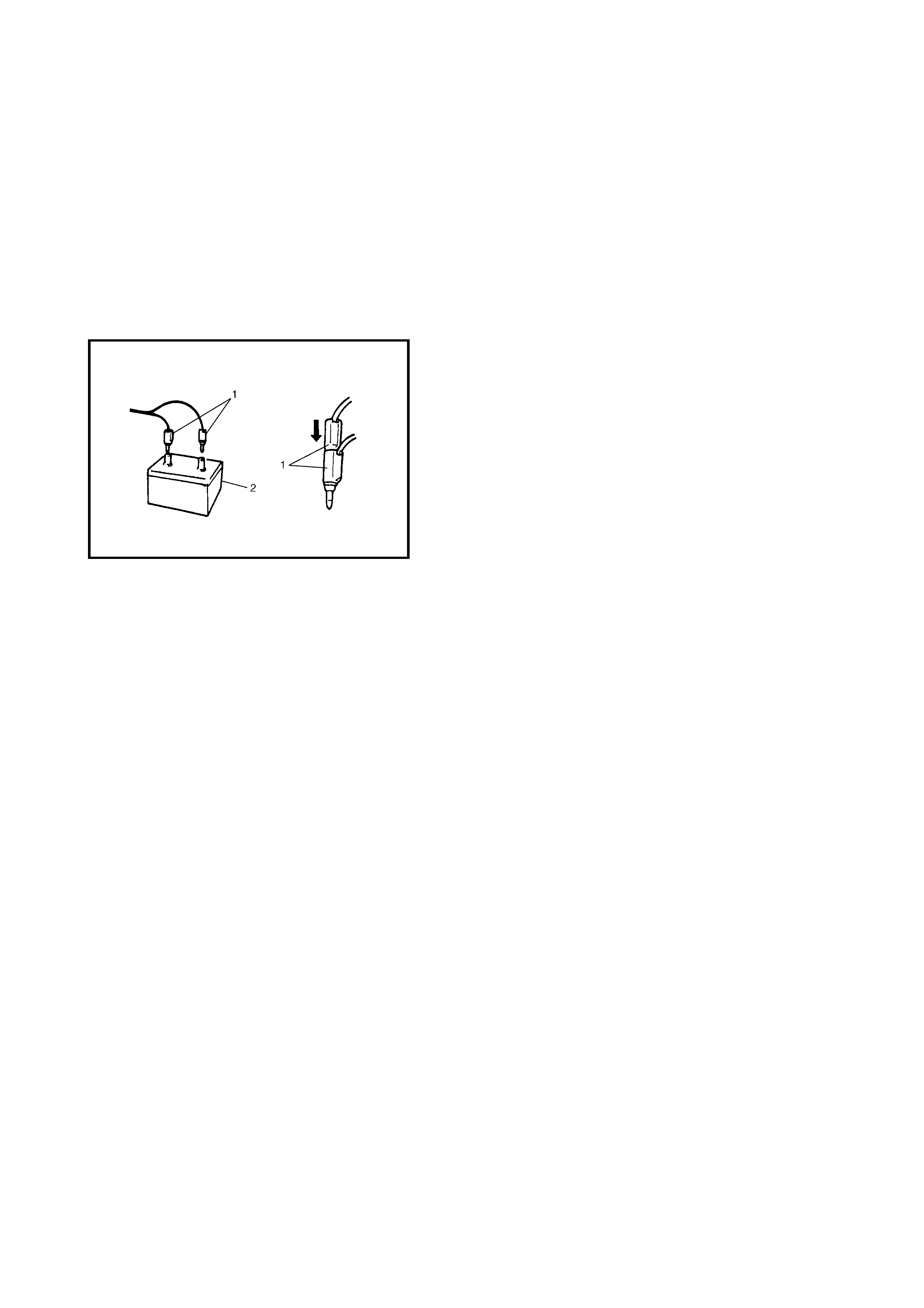
WARNING:
• Do not place the deployed airbag (inflator) module
and act ivate d se at b e lt p re ten sion er n e ar any f lam-
mable objects.
• Do not apply water, oil, etc. to deployed a airbag
(inflator) module or activated seat belt preten-
sioner.
• Wait for about 30 minutes before touching any
met al surface of the airbag (inflator) module or seat
belt pretensioner module.
Failure to follow these procedures may result in fire or
personal injury.
14. Separate the two banana p lugs (1) on th e deployme nt
harness.
15. Connect the deployment harness to the 12 volt power
source (2) to immediately deploy / activate the airbag
(inflator) module or seat belt pretensioner.
16. Disconnect the deployment harness from the power
source and short the two deployment harness leads
together by fully seating one banana plug into the
other.
17. In the unlik ely ev ent that the airb ag (inf lat or ) modul e or
seat belt pretensioner did not deploy / activate after
following these procedures, proceed immediately with
Steps 23 through 26. If the airbag (inflator) module or
the seat belt pretensioner did deploy / activate,
proceed with Steps 18 through 22.
18. Put on a pair of shop gloves to protect your hands from
possible irritation and heat when handling the deployed
airbag (inflator) module and the activated seat belt pre-
tensioner.
19. Disconne ct the adapte r cable fr om the airbag (inflator)
module or the seat belt pretensioner as soon as
possible. This will prevent damage to the adapter cable
due to possible contact with the hot airbag (inflator)
module or seat belt pretentioner.
20. Check the adapter cable as follows.
a. For the airbag (infla tor ) modul e:
The airbag (inflator) module connectors of the
adapter ca ble are desi gned to be r eused. However
they should be inspected for damage after deploy-
ment and replaced if necessary.
b. For the seat belt preten sioner:
The seat belt pretensioner connector of the adapter
cable must be replaced with a spare connector
(speci al tool) .
NOTE: Do not reuse the seat belt pretensioner connec-
tor of the adapter cable as it will be destroyed by the
shock of the pretensioner activation.
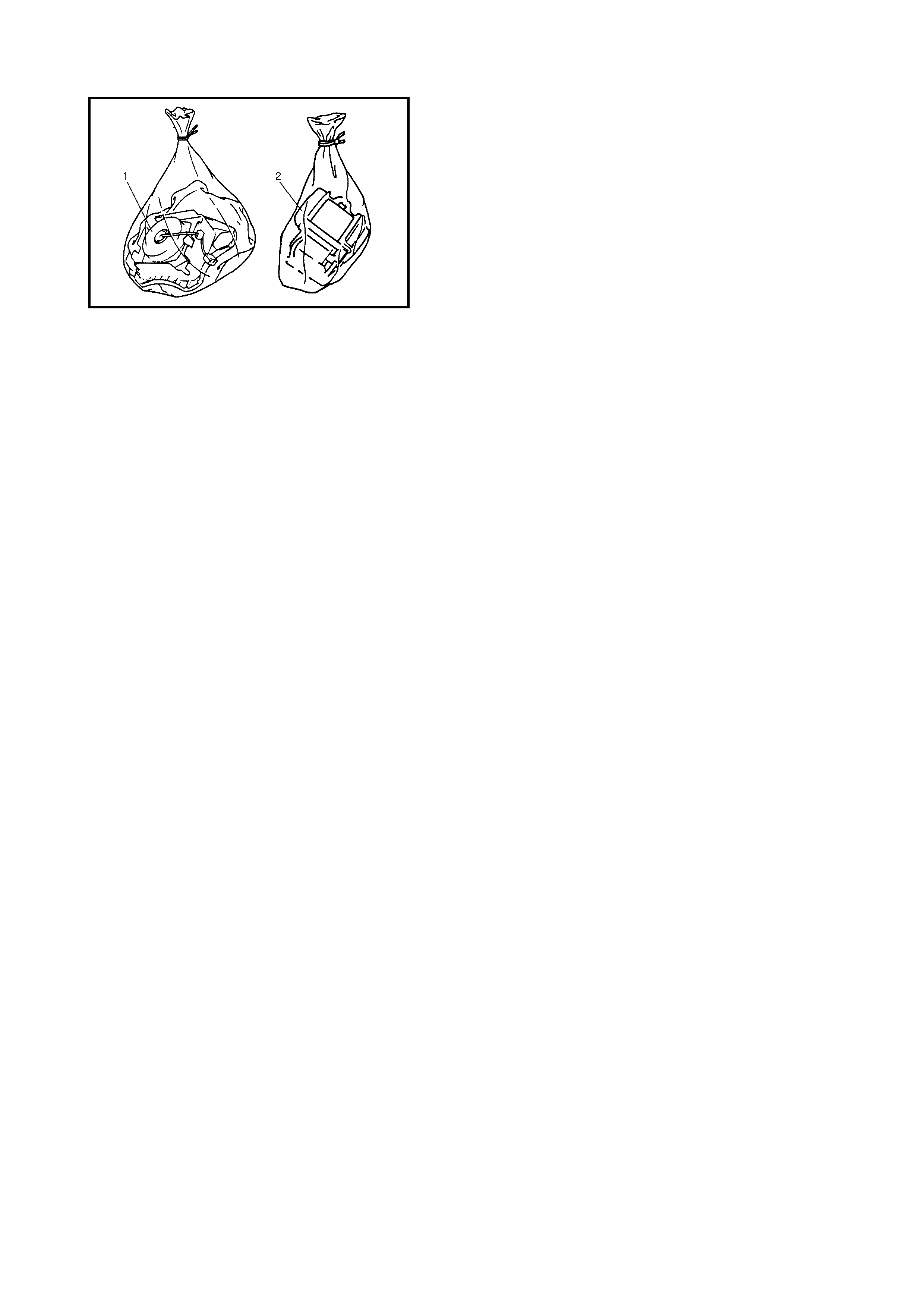
21) Dispose of the deployed airbag (inflator) module (1) or
activated seat belt pretensioner (2) through normal
refuse c han nel s after it ha s cool ed for at lea st 30 m in-
utes and tightly seal the airbag (inflator) module and
the seat belt pretensioner in a strong vinyl bag, refer
to 4.3 DEPLOYED AIRBAG (INFLATOR) MODULE
AND ACTIVATED SEAT BELT PRETENSIONER
DISPOSAL in this Section.
22. Wash your hands with mild soap and water afterward.
NOTE: The remaining steps are to be followed in the
unlikely event that the airbag (inflator) module did not
deploy or the seat belt pretensioner did not activate.
23. Ensure th at the deployment ha rnes s has been discon-
nected from the 12 volt power source and that its two
banana plugs have been shorted together by fully
seating one banana plug into the other.
24. Disconne ct the depl oy me nt ha rn ess a nd adap ter c able
from the airbag (inflator) module or the seat belt pre-
tensioner.
25. Temporarily store the undeployed airbag (inflator)
module or unactivated seat belt pretensioner, refer to
3.1 SERVICE PRECA U TIO NS in this Sec t io n.
26. Contact your local distributor for further assistance.
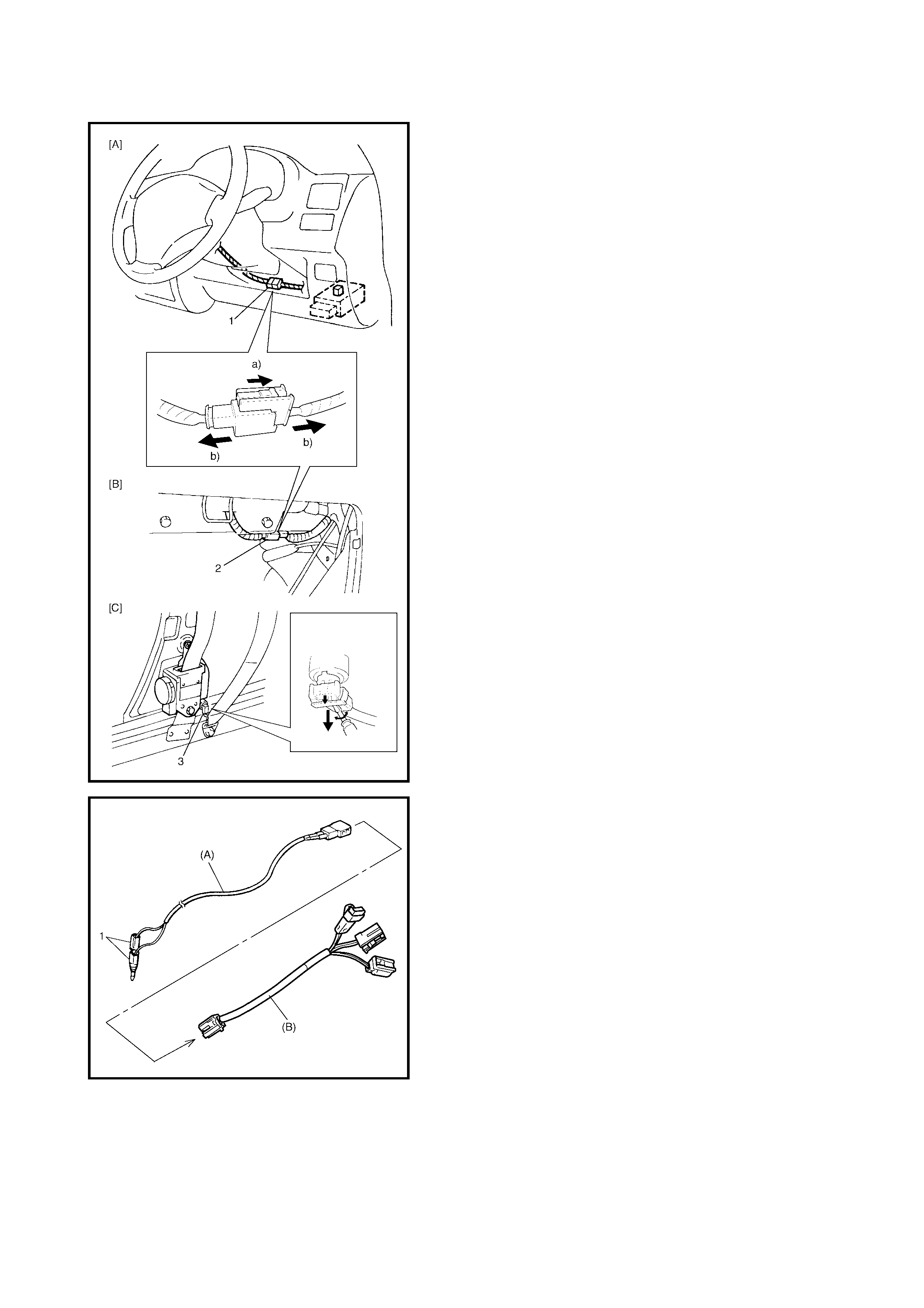
4.2 DEPLOYMENT/ACTIVATION INSIDE VEHICLE
When veh icle will be destr oyed or sal vaged for compone nt
parts, deploy the airb ag (inflator) modul es and activate the
seat belt pretensioners while installed on the vehicle.
1. Turn ignition switch to LOCK, remove the key and put
on safety glasses.
2. Remove all loose objects from the front seats and
instrum ent panel.
3. Disconnect the airbag (inflator) module or seat belt pre-
tensioner connector as follows.
a. For the driver airbag (inflator ) modul e [A]:
Disconnect the contact coil connector (1) located
near the base of the steering column.
b. For the passenger airbag (inflator) module [B]:
Remove the glove box from the instrument panel
and disconnect the passenger airbag (inflator)
module connector (2).
c. Fo r seat belt pr eten si one r [C]:
Remove the driv er an d passeng er si de ce ntre p illar
lower trims and disconnect the seat belt preten-
sioner connectors (3).
4. Confirm that each airbag (inflator) module or seat belt
pretensioner is securely mounted.
5. Check that there is no open, short or damage in the
special tools (A) 09932-75030 deployment harness
and (B) 09932-78331 adapter cable. If any faulty
condition is found, do not use it. Connect the adapter
cable (B) i nto the de plo ym ent har ne ss (A ) and lo ck th e
connectors with the lock sliders.
NOTE: If the adapter cable seat belt pretensioner conne c-
tor is faulty, replace it with the spare connector.
6. Short the two deployment harness leads (1) together
by fully seating one banana plug into the other.
WARNING: The deployment harness is to remain
shorted and not be connected to a 12 volt power
source until the airbag is ready to be deployed or the
seat belt pretensioner is to be activated.
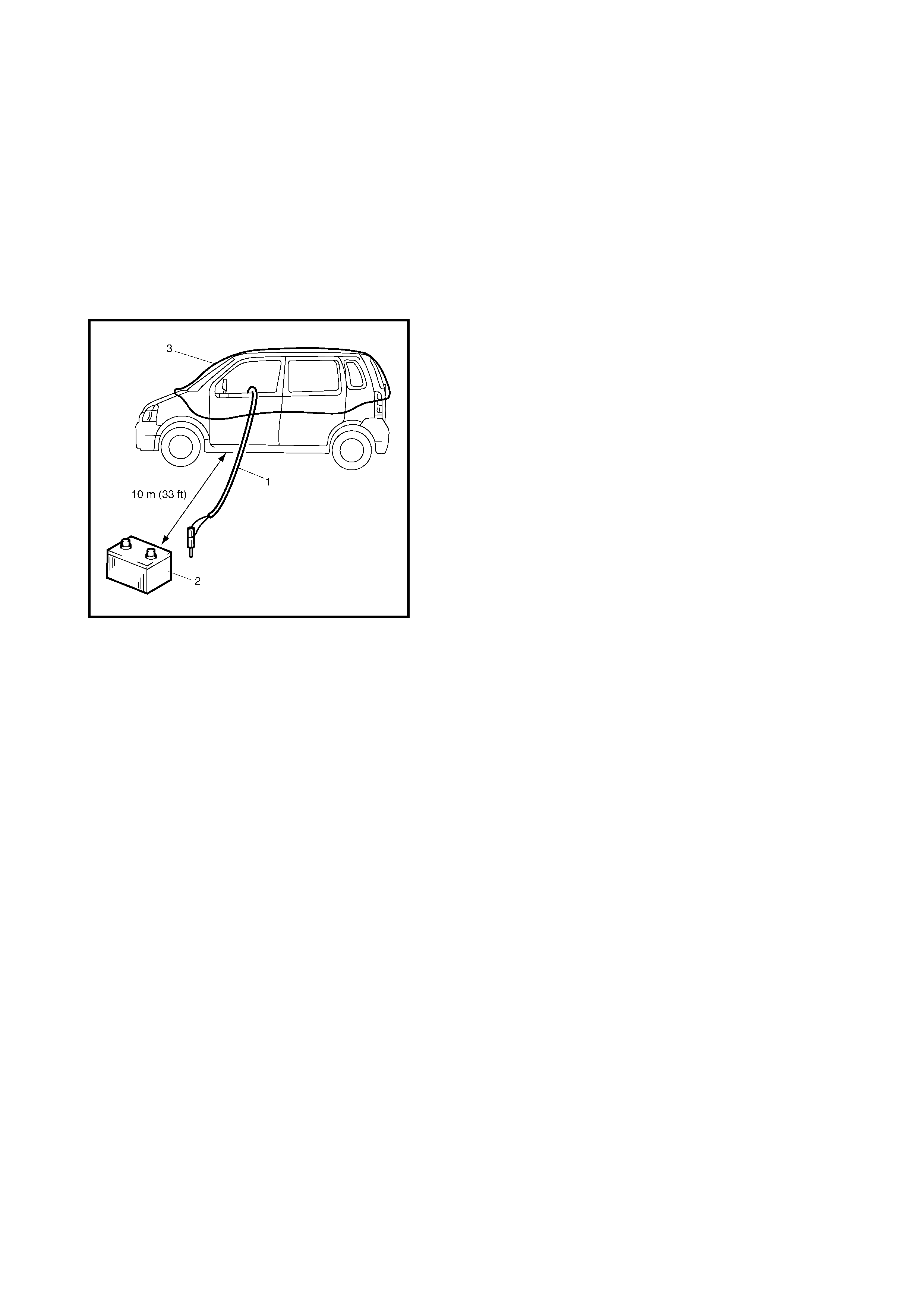
7. Connect the adapter cable (B) in series with the
deployme nt harness (A) to the ai rbag (inflator ) modul e
or seat belt pretensioner as follows.
a. For the airbag (infla tor ) modul e:
Connect the adapter cable (B) in series with the
deployment harness (A) to the driver or passenger
airbag (inflator) module until a click is heard.
b. For the seat belt preten sioner:
Connect the adapter cable (B) in series with the
deployment harness (A) to the seat belt preten-
sioner and lock the connector with the lock slider.
8. Route the deployment (1) harness out of the vehicle.
9. Verify that the inside of the vehicle and the area sur-
rounding the vehicle are clear of all people and loose
or flammable objects.
10. Stretch the deployment harness to its full length 10 m.
11. Place a 12 volt power so urce (2 ) near the shorted end
of the deployment harness. A vehicle battery is sug-
gested.
12. Completely cover the windshield area and front door
window openings with a drop cloth, blanket to similar
(3). This reduces the possibility of injury due to the
possible fragmentation of the vehicle’s glass.
13. Notify a ll people in the im mediate area that y ou intend
to deploy the airbag (inflator) module or activate the
seat belt pretensioner.
NOTE:
• When the airbag (inflator) module deploys and the seat
belt pretensioner activates, the rapid gas expansion
will create a substantial noise. Wear suitable ear pro-
tection. Notify all people in the immediate area that you
intend to dep loy the air ba g ( inf lat or) m odu le or ac tiva te
the seat belt pretensioner and that suitable ear pr otec-
tion should be worn.
• After the airbag (inflator) module has been deployed,
the surface of the airbag may contain a powdery resi-
due. This powder consists primarily of cornstarch (used
to lubricate the bag as it inflates) and by-products of
the chemical reaction.

WARNING:
• Do not place the deployed airbag (inflator) module
and act ivate d se at b e lt p re ten sion er n e ar any f lam-
mable objects.
• Do not apply water, oil, etc. to deployed a airbag
(inflator) module or activated seat belt preten-
sioner.
• Wait for about 30 minutes before touching any
met al surface of the airbag (inflator) module or seat
belt pretensioner module.
Failure to follow these procedures may result in fire or
personal injury.
14. Separate the two banana p lugs (1) on th e deployme nt
harness (2).
15. Connect the deployment harness to a 12 volt power
source (vehicle battery) (3). This will immediately
deploy / activate the airbag or the pretensioner.
16. Disconnect the deployment harness from the power
source and short the two deployment harness leads
together by fully seating one banana plug into the
other.
17. Repeat steps 2 through 16 to deploy / activate the
airbag (inflator) modules or seat belt pretensioners
which have not been deployed or activated.
18. In t he un l ike ly ev ent t ha t an ai r ba g ( i nf l a to r) modu l e d id
not deploy or acti va te after follow ing thes e pro cedur es ,
proceed immediately with steps 24 through 26. If the
airbag (inflator) module and seat belt pretensioner did
deploy / activate, proceed with steps 19 through 23.
19. Carefully remove the drop cloth from the vehicle and
clean off any fragments or discard it entirely.
20. Put on a pair of shop gloves to protect your hands from
possible irritation and heat when handling the deployed
airbag (inflator) module and the activated seat belt pre-
tensioner.
21. Disconne ct the adapte r cable fr om the airbag (inflator)
module or seat belt pretensioner as soon as possible.
This will prevent damage to the adapter cable due to
possible contact with the hot airbag (inflator) module
and seat belt pretensioner.

22. Check the adapter cable as follows.
a. For the airbag (infla tor ) modul e:
The airbag (inflator) module connectors of the
adapter ca ble are desi gned to be r eused. However
they should be inspected for damage after deploy-
ment and replaced if necessary.
b. For the seat belt preten sioner:
The seat belt pretensioner connector of the adapter
cable must be replaced with a spare connector
(speci al tool) .
NOTE: Do not reuse the seat belt pretensioner connec-
tor of the adapter cable as it will be destroyed by the
shock of the pretensioner activation.
23. With the airbag (inflator) modules deployed and seat
belt pretensioners activated, the vehicle may be
scrapped in the same manner as a non-airbag / seat
belt pretensioner system equipped vehicle.
NOTE: The following steps are to be followed in the
unlikely event that the airbag (inflator) module did not
deploy or seat belt pretensioner did not activate.
24. Remove the undeployed airbag (inflator) module(s)
and the unactivated seat belt pretensioner(s) from the
vehicle. For the driver airbag (inflator) module refer to
Section 3C, 3.2 DRIVER AIRBAG (INFLATOR)
MODULE. For the passenger airbag (inflator) module
refer to 3.4 PASSENGER AIRBAG (INFLATOR)
MODULE in this Se ct i o n. F or t h e seat be l t p ret e ns i one r
refer to Section 10, 3.2 FRONT SEAT BELT
ASSEMBLY.
25. Temporarily store the undeployed airbag (inflator)
module and/or unactivated seat belt pretensioner, refer
to 3.1 SERVICE PRECAUTIONS in this Section.
26. Contact your local distributor for further assistance.
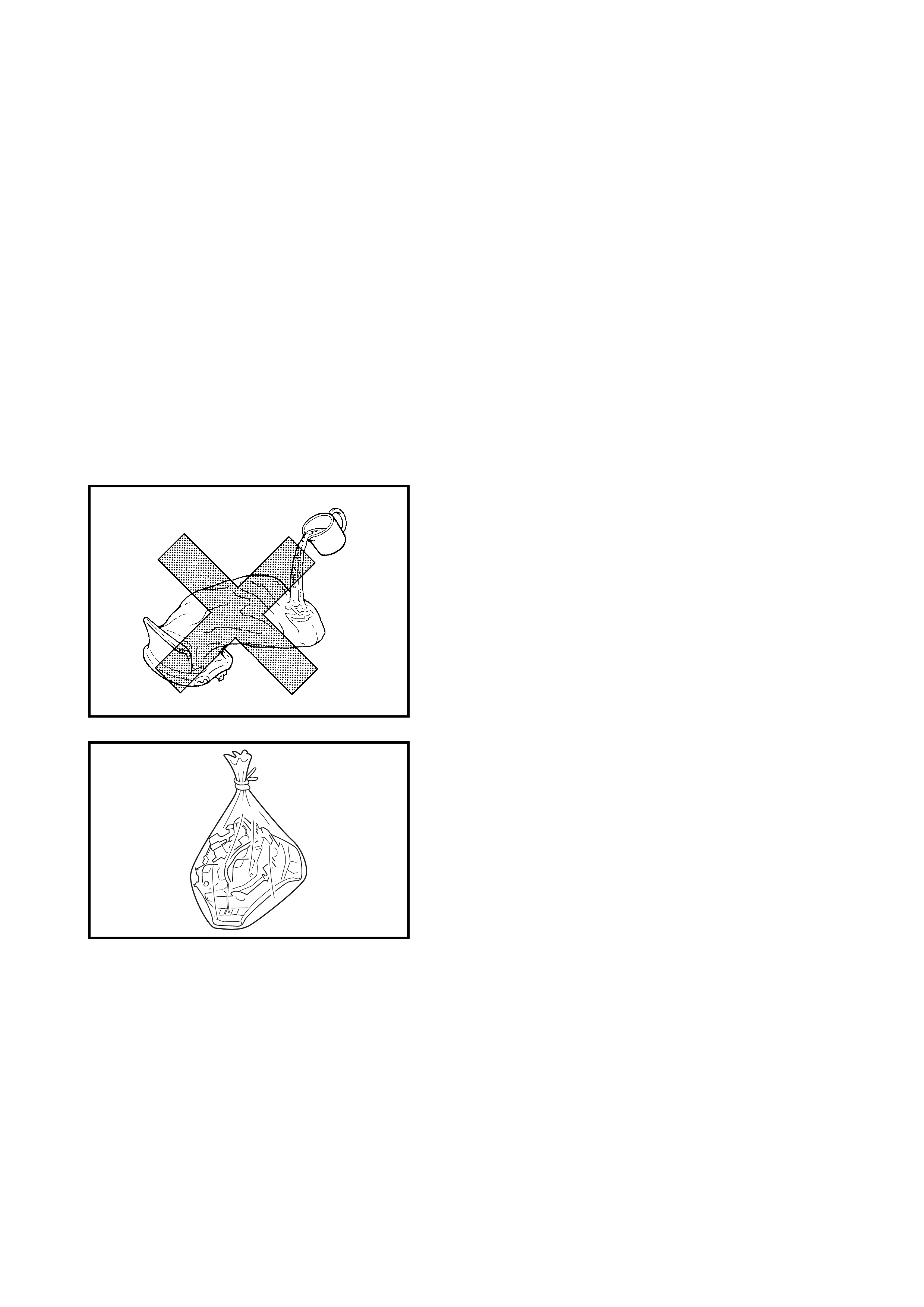
4.3 DEPLOYED AIRBA G (INFLATOR) MODULE AND ACTIVATED
SEAT BELT PRETENSIONER DISPOSAL
WARNING:
• Failure to follow proper airbag (inflator) module
and seat belt pretensioner disposal procedures
can result in airbag deployment and pretensioner
activation, which may cause personal injury.
• The undeployed airbag (inflator) module and the
inactivated seat belt pretensioner must not be
disposed of through normal refuse channels.
• The undeployed airbag (inflator) module and the
inactivated seat belt pretensioner contains
substances that can cause severe illness or
personal injury if the sealed container is damaged
during disposal.
A deploy ed airbag (infla tor) modu le and activate d seat belt
pretensioner can be disposed of through normal refuse
channels. For disposal the following points should be
noted.
• Immediately after deployment / activation, the airbag
(inflato r) modu le and the seat belt pr etensioner is very
hot. Wait for 30 minutes for it to cool off before handling
it.
• Never app ly water, oil , etc. to a deploy ed airbag (inf la-
tor) module and activated seat belt pretensioner.
• After the airbag (inflator) module has been deployed,
the surface of the airbag may contain a powdery resi-
due. This powder consists primarily of cornstarch (used
to lubricate the bag as it inflates) and by-products of
the chemical reaction. As with many service proce-
dures, wear gloves and safety glasses.
• When disposing of the deployed airbag (inflator) mod-
ule and the activa ted seat belt pretensioner, seal it in
a vinyl bag.
• When an airbag (inflator) module and seat belt preten-
sioner have been deployed / activated inside the vehi-
cle which to be scrapped, leave them installed in the
vehicle.
• Wash your han ds with mi ld so ap and wa ter a fter work
is completed.
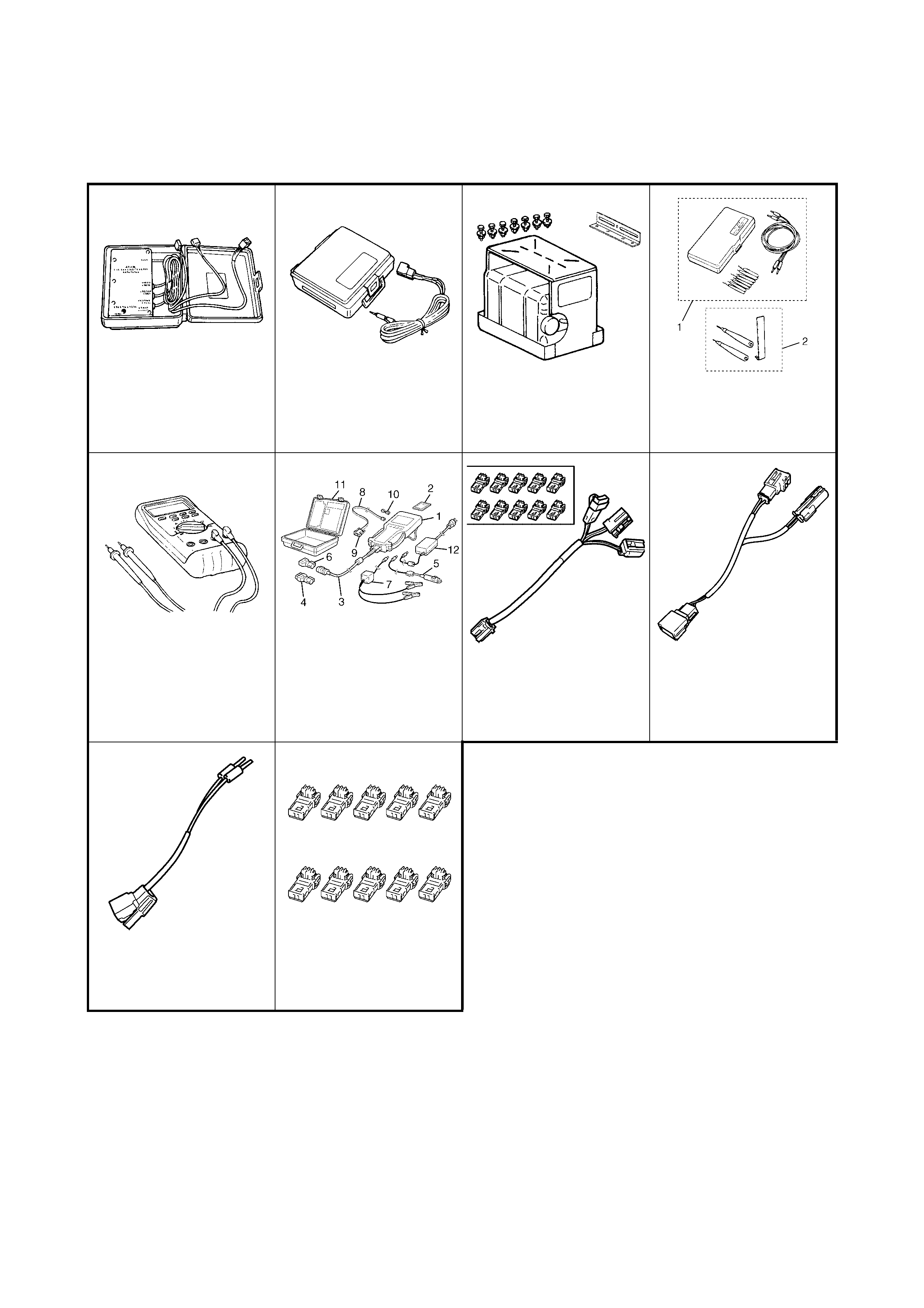
5. SPECIAL TO OLS
NOTE: Refer to Section 0A GENERAL INFORMATION – 7. CONSOLIDATED TOOLS for a detailed list of
special tools and the local equivalent if one is available.
WARNING: To avoid
airbag deployment or personal injury, use the sp ecified digital multimeter.
NOTE:
A: This set includes the following items:
1. Connector test adapter kit 09932-75020,
2. Connector test adapter and shorting bar release tool 09932-76020.
B: Digital multimeter specification: The maximum test current is 10 mA or less at the minimum range of
resistance measurement.
C: This kit includes the following items:
1. Tech 2, 2. PCMCIA card, 3. DLC cable, 4. SAE 16 / 19 adapter, 5. Cigarette cable,
6. DLC loopback adapter, 7. Battery power cable, 8. RS232 adapter, 9. RS232 loopback connector,
10. Storage case, 11. Power supply.
D: These connectors are spares for adapter cable 09932-78331.
09932-75010 09932-75030 09932-75041 09932-76010
Airbag driver/passenger
load tool Airbag deployment
harness Passenger airbag mod-
ule deploy me nt fixtur e Connector test adapter
set (see Note A)
09932-78331 09932-78340
Digital mult im ete r
(see Note B &
WARNING
)
Tech 2 kit
(see Note C) Adapter cable Adapter cable
09932-78310 09932-75410
Adapter cable Spare connector
(see Note D)