
10B
SECTION 10B1 - AIR BAG SYSTEM (2004 UPDATE)
WARNING:
• Service on or around the air bag system components or wiring must be performed only by an
authorized HOLDEN dealer. Please observe all WARNINGs and “Service Precautions” under “On-
Vehicle Service” in this section before performing service on or around the air bag system compo-
nents or wiring. Failure to follow WARNINGs could result in unintended activation of the system or
could render the system inoperative. Either of these two conditions ma y result in severe injury.
• The procedures in this section must be followed in the order listed to disable the air bag system
temporarily and prevent false diagnostic trouble codes from setting. Failure to follow procedures
could result in possible activation of the air bag system, personal injury or otherwise unneeded air
bag system repairs.
CAUTION:
When fasteners are removed, always reinstall them at the same location from which they were
removed. If a fastener needs to be replaced, use the correct part number fastener for that application.
If the correct part number fastener is not available, a fastener of equal size and strength (or stronger)
may be used. Fasteners that are not reused, and those requiring thread-locking compound, will be
called out. The correct torque value must be used when installing fasteners that require it. If the
above conditions are not followed, parts or system damage could result.
NOTE:
For the items not listed below, refer to the Section 10B.
General Description
System Components and Wiring Location View and Connectors
Diagnosis
DTC B1021 – Driver Air Bag Initiator Circuit Resistance High
DTC B1022 – Driver Air Bag Initiator Circuit Resistance Low
DTC B1024 – Driver Air Bag Initiator Circuit Short to Ground
DTC B1025 – Driver Air Bag Initiator Circuit Short to Power Circuit
Air Bag (Inflator) Module and Seat Belt Pretensioner Disposal
Deployment/Activation Outside of Vehicle
Special Tool
General Description
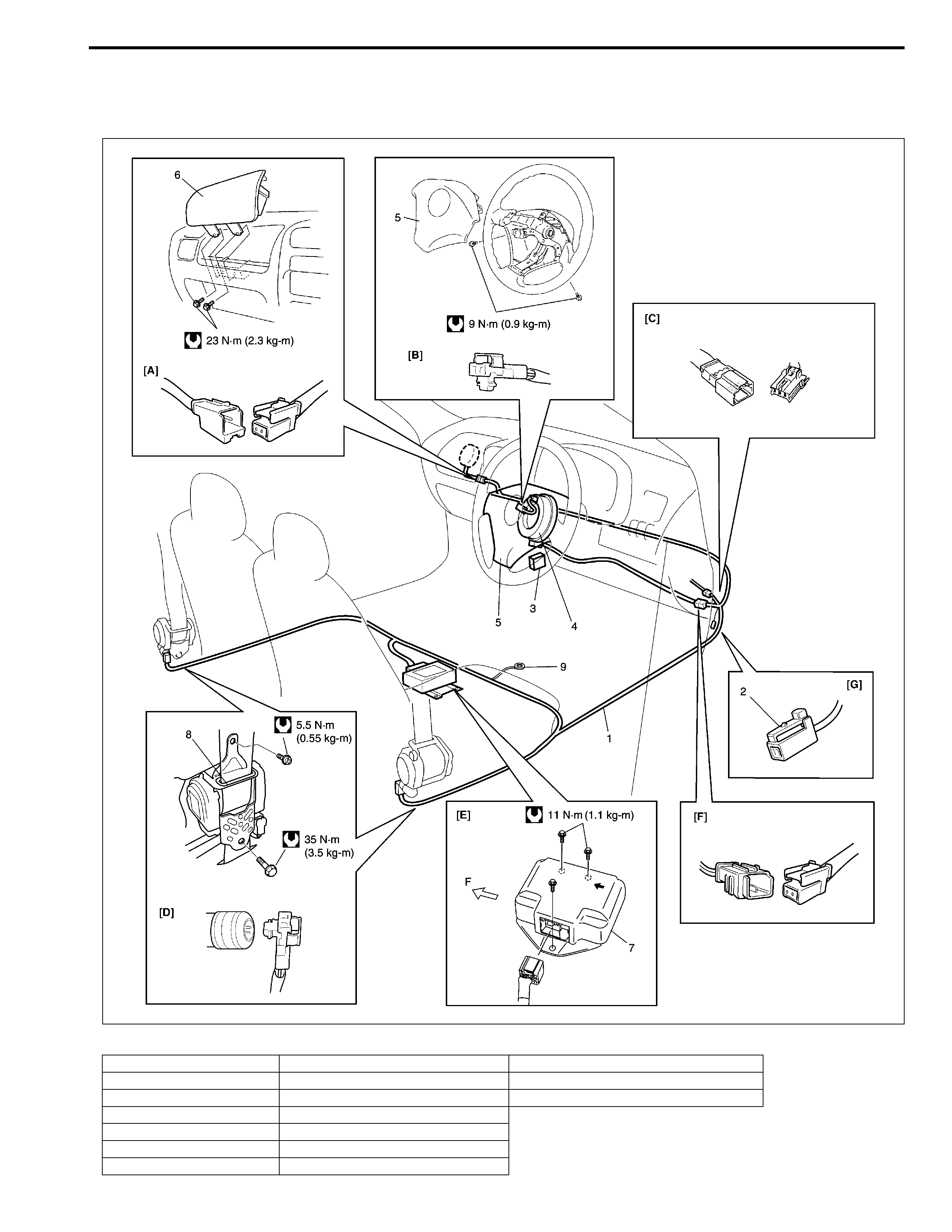
System Components and Wiring Location View and Connectors
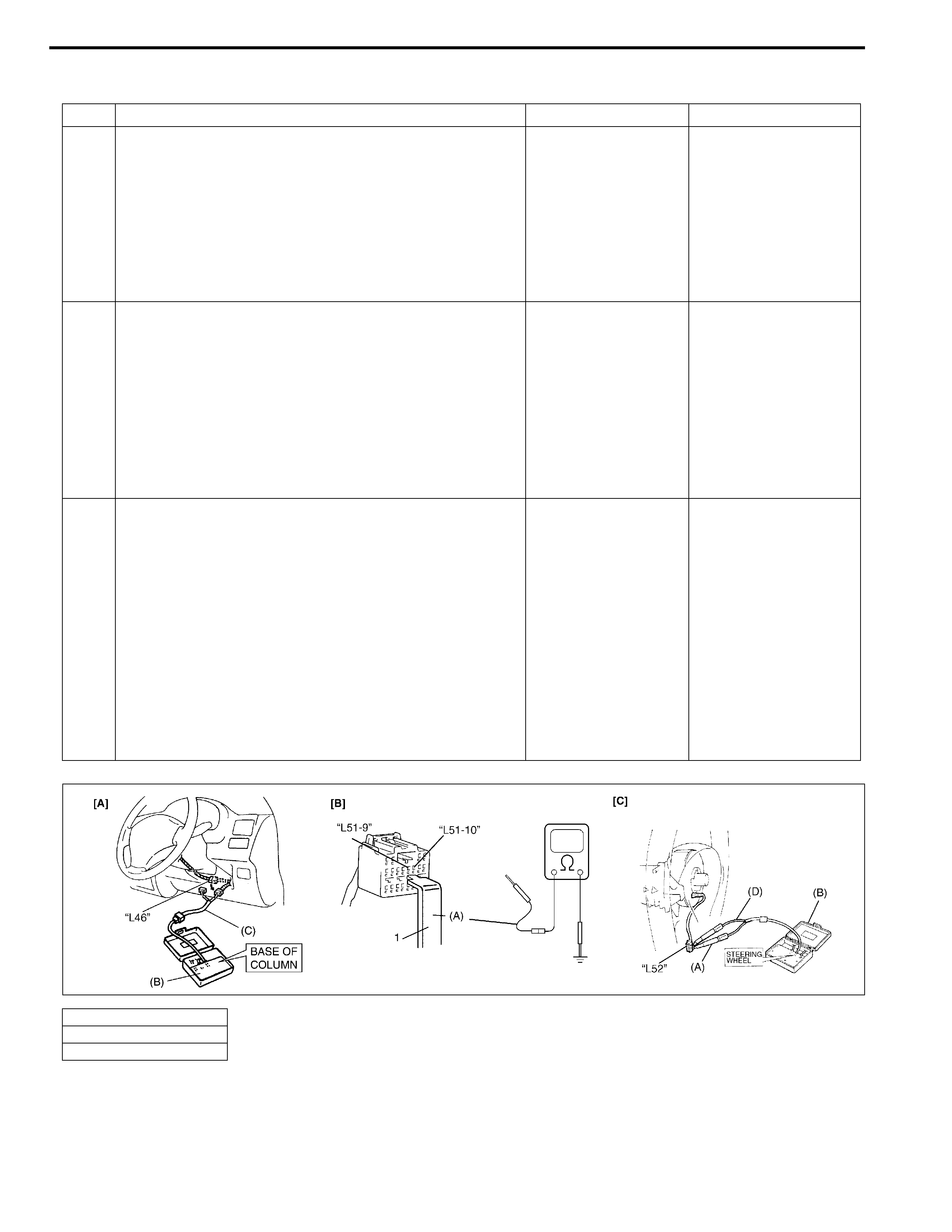
[A] : Connector “L47” F : Forward 7. SDM
[B] : Connector “L52” 1. Air bag harness (in floor harness) 8. Seat belt pretensioner (retractor assembly)
[C] : Connector “L45”, “G39” 2. “Air bag” monitor coupler 9. Ground for air bag system
[D] : Connector “L49”, “L50” 3. DLC
[E] : Connector “L51” 4. Contact coil assembly
[F] : Connector “L46” 5. Driver air bag (inflator) module
[G] : Connector “L48” 6. Passenger air bag (inflator) module
Diagnosis
DTC B1021 – Driver Air Bag Initiator Circuit Resistance High
DTC B1022 – Driver Air Bag Initiator Circuit Resistance Low
DTC B1024 – Driver Air Bag Initiator Circuit Short to Ground
DTC B1025 – Driver Air Bag Initiator Circuit Short to Power Circuit
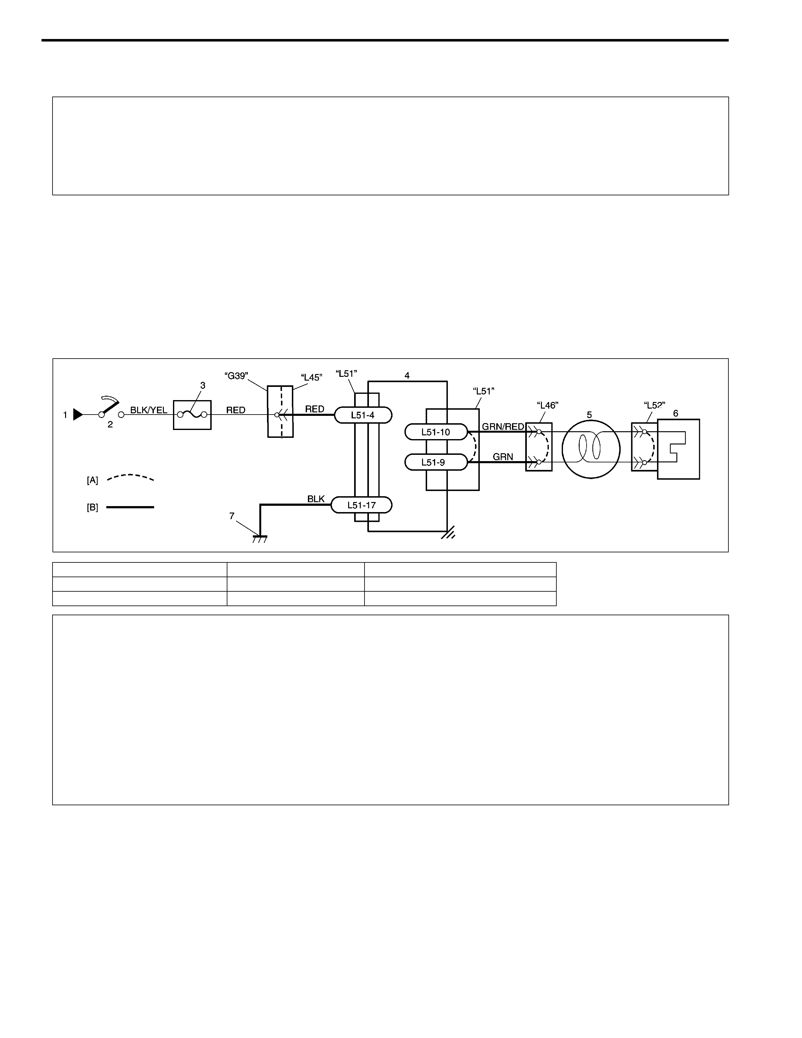
Wiring Diagram
DTC Will Be Set When
DTC B1021 :
The combined resistance of the driver air bag (inflator) module, contact coil assembly, harness wiring and con-
nector terminal contact is above a specified value for specified time.
DTC B1022 :
The combined resistance of the driver air bag (inflator) module, contact coil assembly, harness wiring and con-
nector terminal contact is below a specified value for specified time.
DTC B1024 :
The voltage measured at driver air bag initiator circuit is below a specified value for specified time.
WARNING:
To avoid deployment when troubleshooting the air bag system, do not use electrical test equipment
such as a battery powered or AC powered voltmeter, ohmmeter, etc., or any type of electrical equip-
ment other than that specified in this manual. Do not use a non-powered probe type tester.
Instructions in this manual must be followed carefully, otherwise personal injury may result.
[A] : Shorting bar 2. Ignition switch 5. Contact coil assembly
[B] : Air bag harness in floor harness 3. “AIR BAG” fuse 6. Driver air bag (inflator) module
1. From main fuse 4. SDM 7. Ground for air bag system
CAUTION:
• Be sure to perform “Air Bag Diagnostic System Check” in this section before starting diagnosis
according to flow table.
• When measurement of resistance or voltage is required in this table, use a specified digital multim-
eter (Refer to “Special Tool” in this section.) along with a correct terminal adapter from special tool
(Connector test adapter kit).
• When a check for proper connection is required, refer to “Intermittent and Poor Connections” in
this section.
• If there is open circuit in the air bag wire harness, connector or terminal is found damaged, replace
the wire harness, connector and terminal as an assembly.

DTC B1025 :
The voltage measured at driver air bag initiator circuit is above a specified value for specified time.
Table Test Description
DTC B1021, B1022, B1024 and B1025 :
STEP 1 : Check whether malfunction is in contact coil and driver air bag (inflator) module or the others.
STEP 2 : Check driver air bag (inflator) module initiator circuit in air bag harness.
STEP 3 : Check whether malfunction is in contact coil or driver air bag (inflator) module.
Diagnostic Flow Table
DTC B1021 : Driver Air Bag Initiator Circuit Resistance High
Step Action Yes No
1 1) With ignition switch OFF, disconnect contact coil con-
nector located near the base of the steering column.
2) Check proper connection to contact coil at terminals
in “L46” connector.
3) If OK then connect special tools (B) and (C) to contact
coil connector disconnected at step 1).
With ignition switch ON, is DTC B1021 current?
Go to step 2. Go to step 3.
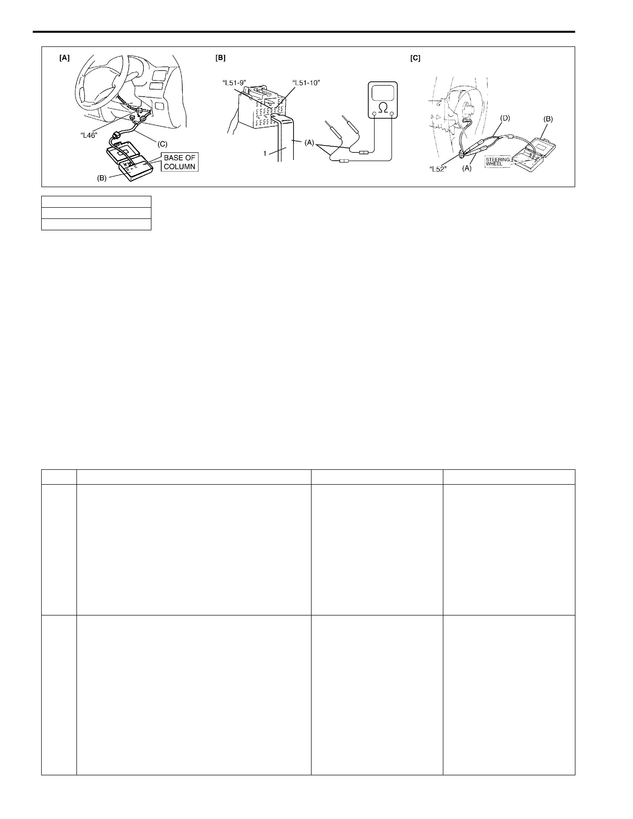
2 1) With ignition switch OFF, disconnect SDM connector.
2) Check proper connection to SDM at terminals “L51-9”
and “L51-10”.
3) If OK, release shorting bar in SDM connector insert-
ing release tool (1) included in special tool (A).
4) Measure resistance between “L51-9” and “L51-10”
terminals with connected special tools (B) and (C) to
“L46” connector.
Is resistance 4.5 Ω or less?
Substitute a known-
good SDM and
recheck.
Repair high resis-
tance or open in
“GRN” or “GRN/RED”
wire circuit.
3 1) With ignition switch OFF, disconnect special tools (B)
and (C) from “L46” connector then reconnect contact
coil connector located near the base of the steering
column as it was.
2) Remove driver air bag (inflator) module from steering
wheel (Refer to “Driver Air Bag (Inflator) Module” in
Section 3C).
3) Check proper connection to driver air bag (inflator)
module at terminals in “L52” connector.
4) If OK then connect special tools (A), (B) and (D) to
“L52” connector.
With ignition switch ON, is DTC B1021 current?
Ignition switch OFF.
Replace contact coil
assembly (Refer to
“Contact Coil and
Combination Switch
Assembly” in Sec-
tion 3C).
Ignition switch OFF.
Replace driver air
bag (inflator) module
(Refer to “Driver Air
Bag (Inflator) Module”
in Section 3C).
Special tool
(A) : 09932-76010
(B) : 09932-75010
(C) : 09932-78340
(D) : 09932-78310
DTC B1022 : Driver Air Bag Initiator Circuit Resistance Low
[A] : Fig. for Step 1 and 2
[B] : Fig. for Step 2
[C] : Fig. for Step 3
NOTE:
Upon completion of inspection and repair work, perform following items.
• Reconnect all air bag system components, ensure all components are properly mounted.
• Clear diagnostic trouble codes (Refer to “DTC Clearance” in this section), if any.
• Repeat “Air Bag Diagnostic System Check” in this section to confirm that the trouble has been cor-
rected.
Step Action Yes No
1 1) With ignition switch OFF, disconnect contact
coil connector located near the base of the
steering column.
2) Check proper connection to contact coil at
terminals in “L46” connector.
3) If OK then connect special tools (B) and (C)
to contact coil connector disconnected at
step 1).
With ignition switch ON, is DTC B1022 current?
Go to step 2. Go to step 3.
2 1) With ignition switch OFF, disconnect SDM
connector.
2) Check proper connection to SDM at termi-
nals “L51-9” and “L51-10”.
3) If OK, release shorting bar in SDM connec-
tor inserting release tool (1) included in spe-
cial tool (A).
4) Measure resistance between “L51-9” and
“L51-10” terminals with connected special
tools (B) and (C) to “L46” connector.
Is resistance 1.7 Ω or more?
Substitute a known-good
SDM and recheck.
Repair short from “GRN”
wire circuit to “GRN/RED”
wire circuit or from “GRN”
or “GRN/RED” wire cir-
cuit to other wire circuit.
Special tool
(A) : 09932-76010
(B) : 09932-75010
(C) : 09932-78340
(D) : 09932-78310
3 1) With ignition switch OFF, disconnect special
tools (B) and (C) from “L46” connector then
reconnect contact coil connector located
near the base of the steering column as it
was.
2) Remove driver air bag (inflator) module
from steering wheel (Refer to “Driver Air
Bag (Inflator) Module” in Section 3C).
3) Check proper connection to driver air bag
(inflator) module at terminals in “L52” con-
nector.
4) If OK then connect special tools (A), (B) and
(D) to “L52” connector.
With ignition switch ON, is DTC B1022 current?
Ignition switch OFF.
Replace contact coil
assembly (Refer to “Con-
tact Coil and Combina-
tion Switch Assembly” in
Section 3C).
Ignition switch OFF.
Replace driver air bag
(inflator) module (Refer to
“Driver Air Bag (Inflator)
Module” in Section 3C).
Step Action Yes No
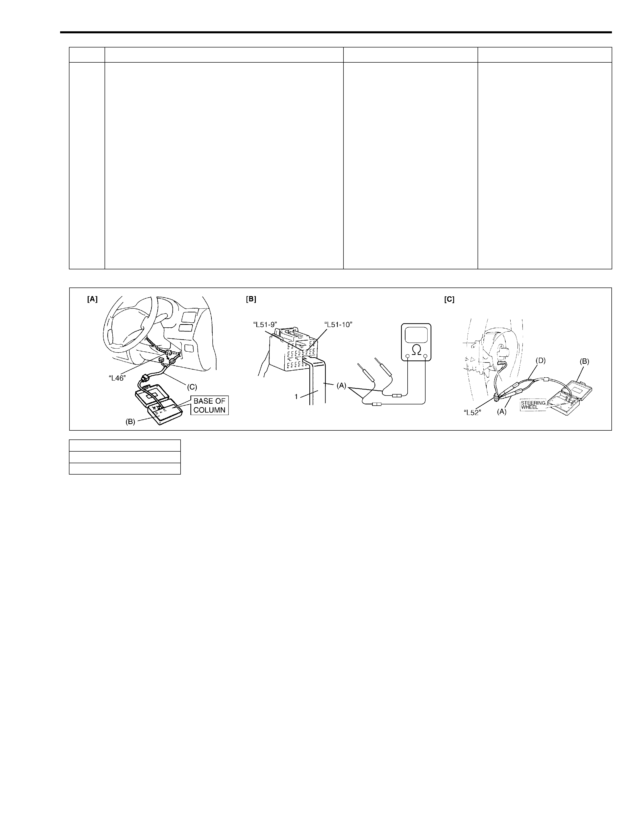
[A] : Fig. for Step 1 and 2
[B] : Fig. for Step 2
[C] : Fig. for Step 3
NOTE:
Upon completion of inspection and repair work, perform following items.
• Reconnect all air bag system components, ensure all components are properly mounted.
• Clear diagnostic trouble codes (Refer to “DTC Clearance” in this section), if any.
• Repeat “Air Bag Diagnostic System Check” in this section to confirm that the trouble has been cor-
rected.
DTC B1024 : Driver Air Bag Initiator Circuit Short to Ground
Special tool
(A) : 09932-76010
(B) : 09932-75010
(C) : 09932-78340
(D) : 09932-78310
Step Action Yes No
1 1) With ignition switch OFF, disconnect contact coil
connector located near the base of the steering col-
umn.
2) Check proper connection to contact coil at terminals
in “L46” connector.
3) If OK then connect special tools (B) and (C) to con-
tact coil connector disconnected at step 1).
With ignition switch ON, is DTC B1024 current?
Go to step 2. Go to step 3.
2 1) With ignition switch OFF, disconnect special tools
(B) and (C) from “L46” connector and SDM connec-
tor from SDM respectively.
2) Release shorting bar in SDM connector inserting
release tool (1) included in special tool (A).
3) Measure resistance between “L51-9” terminal and
body ground and between “L51-10” terminal and
body ground.
Is resistance infinity?
Substitute a known-
good SDM and
recheck.
Repair short from
“GRN” or “GRN/RED”
wire circuit to ground.
3 1) With ignition switch OFF, disconnect special tools
(B) and (C) from “L46” connector then reconnect
contact coil connector located near the base of the
steering column as it was.
2) Remove driver air bag (inflator) module from steer-
ing wheel (Refer to “Driver Air Bag (Inflator) Module”
in Section 3C).
3) Check proper connection to driver air bag (inflator)
module at terminals in “L52” connector.
4) If OK then connect special tools (A), (B) and (D) to
“L52” connector.
With ignition switch ON, is DTC B1024 current?
Ignition switch OFF.
Replace contact coil
assembly (Refer to
“Contact Coil and
Combination Switch
Assembly” in Sec-
tion 3C).
Ignition switch OFF.
Replace driver air bag
(inflator) module
(Refer to “Driver Air
Bag (Inflator) Module”
in Section 3C).
[A] : Fig. for Step 1 and 2
[B] : Fig. for Step 2
[C] : Fig. for Step 3

DTC B1025 : Driver Air Bag Initiator Circuit Short to Power Circuit
NOTE:
Upon completion of inspection and repair work, perform following items.
• Reconnect all air bag system components, ensure all components are properly mounted.
• Clear diagnostic trouble codes (Refer to “DTC Clearance” in this section), if any.
• Repeat “Air Bag Diagnostic System Check” in this section to confirm that the trouble has been cor-
rected.
Step Action Yes No
1 1) With ignition switch OFF, disconnect contact
coil connector located near the base of the
steering column.
2) Check proper connection to contact coil at
terminals in “L46” connector.
3) If OK then connect special tools (B) and (C)
to contact coil connector disconnected at
step 1).
With ignition switch ON, is DTC B1025 current?
Go to step 2. Go to step 3.
2 1) With ignition switch OFF, disconnect special
tools (B) and (C) from “L46” connector and
SDM connector from SDM respectively.
2) Release shorting bar in SDM connector
inserting release tool (1) included in special
tool (A).
3) Measure voltage from “L51-9” terminal to
body ground and from “L51-10” terminal to
body ground.
With ignition switch ON, are they 1 V or less?
Substitute a known-good
SDM and recheck.
Repair short from “GRN”
or “GRN/RED” wire cir-
cuit to power circuit.
3 1) With ignition switch OFF, disconnect special
tools (B) and (C) from “L46” connector then
reconnect contact coil connector located
near the base of the steering column as it
was.
2) Remove driver air bag (inflator) module
from steering wheel (Refer to “Driver Air
Bag (Inflator) Module” in Section 3C).
3) Check proper connection to driver air bag
(inflator) module at terminals in “L52” con-
nector.
4) If OK then connect special tools (A), (B) and
(D) to “L52” connector.
With ignition switch ON, is DTC B1025 current?
Ignition switch OFF.
Replace contact coil
assembly (Refer to “Con-
tact Coil and Combina-
tion Switch Assembly” in
Section 3C).
Ignition switch OFF.
Replace driver air bag
(inflator) module (Refer to
“Driver Air Bag (Inflator)
Module” in Section 3C).

Special tool
(A) : 09932-76010
(B) : 09932-75010
(C) : 09932-78340
(D) : 09932-78310
[A] : Fig. for Step 1 and 2
[B] : Fig. for Step 2
[C] : Fig. for Step 3
NOTE:
Upon completion of inspection and repair work, perform following items.
• Reconnect all air bag system components, ensure all components are properly mounted.
• Clear diagnostic trouble codes (Refer to “DTC Clearance” in this section), if any.
• Repeat “Air Bag Diagnostic System Check” in this section to confirm that the trouble has been cor-
rected.

Air Bag (Inflator) Module and Seat Belt Pretensioner Disposal
Air bag (inflator) module/seat belt pretensioner can be deployed/activated inside or outside of vehicle. Deploy-
ment/Activation method used depends upon final disposition of vehicle. Review the following instructions in
order to determine which will work best in a given situation.
Deployment/Activation Outside of Vehicle :
When you intend to return the vehicle to service, deploy the air bag (inflator) module(s) or activate seat belt pre-
tensioner(s) outside of the vehicle.
Deployment/Activation Inside of Vehicle :
When the vehicle will be destroyed, or salvaged for component parts, deploy the air bag modules and/or activate
seat belt pretensioners installed on vehicle.
WARNING:
Failure to follow proper air bag (inflator) module and seat belt pretensioner disposal procedures can
result in air bag deployment and pretensioner activation which may cause personal injury.
Do not dispose of live (undeployed) air bag (inflator) modules and seat belt pretensioners. Because
undeployed air bag (inflator) module/inactivated seat belt pretensioner must not be disposed of
through normal refuse channels.
Undeployed air bag (inflator) module and inactivated seat belt pretensioner contain substances that
can cause severe illness or personal injury if sealed container is damaged during disposal.
WARNING:
The following precautions must be observed for this work. Failure to observe any of them may result
in personal injury.
• Procedure should be followed strictly as described here.
• Be sure to read “Service Precautions” in this section beforehand.
• To avoid accidental deployment/activation, this work should be performed by no more than one per-
son.
• Since smoke is produced when air bag (inflator) module is deployed and pretensioner is activated,
select well-ventilated area.
• Air bag (inflator) module and seat belt pretensioner will immediately deploy/activate when 12 volts
vehicle battery is connected to it. Wear safety glasses throughout this entire deployment/activation
and disposal procedure.
• Wear suitable ear protection when deploying air bag (inflator) module/activating seat belt preten-
sioner. Also, advise those who are in area close to deployment/activation site to wear suitable ear
protection.
• Do not deploy/activate two or more air bag system components (air bag (inflator) modules and seat
belt pretensioners) at the same time.
• Never connect deployment harness to any 12 volts vehicle battery before connecting deployment
harness to air bag (inflator) module and seat belt pretensioner. Deployment harness shall remain
shorted and not be connected to 12 volts vehicle battery till you are ready to deploy air bag (inflator)
module or activate seat belt pretensioner.

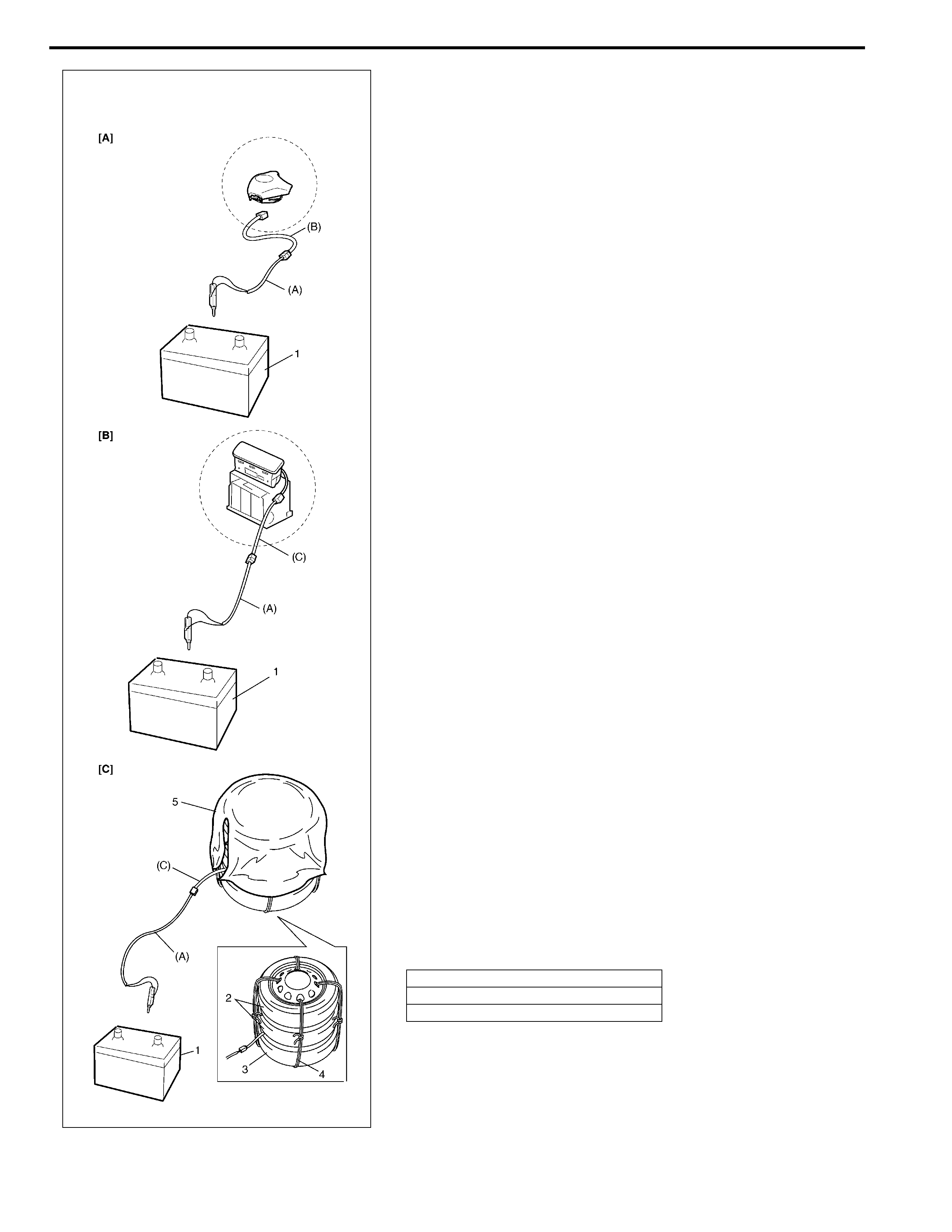
Deployment/Activation Outside of Vehicle
When you intend to return the vehicle to service, deploy the air
bag (inflator) module(s) or activate seat belt pretensioner(s) out-
side of the vehicle.
1) Turn ignition switch to “LOCK” position and remove key.
2) Wear safety glasses during this deployment/activation proce-
dure.
3) Check that there is no open, short or damage in special tools
(deployment harness (A) and adapter cable (B), (C)). If any
faulty is found, do not use it and be sure to use new deploy-
ment harness (A).
Special tool
(A) : 09932-75031
(B) : 09932-76510
(C) : 09932-78332
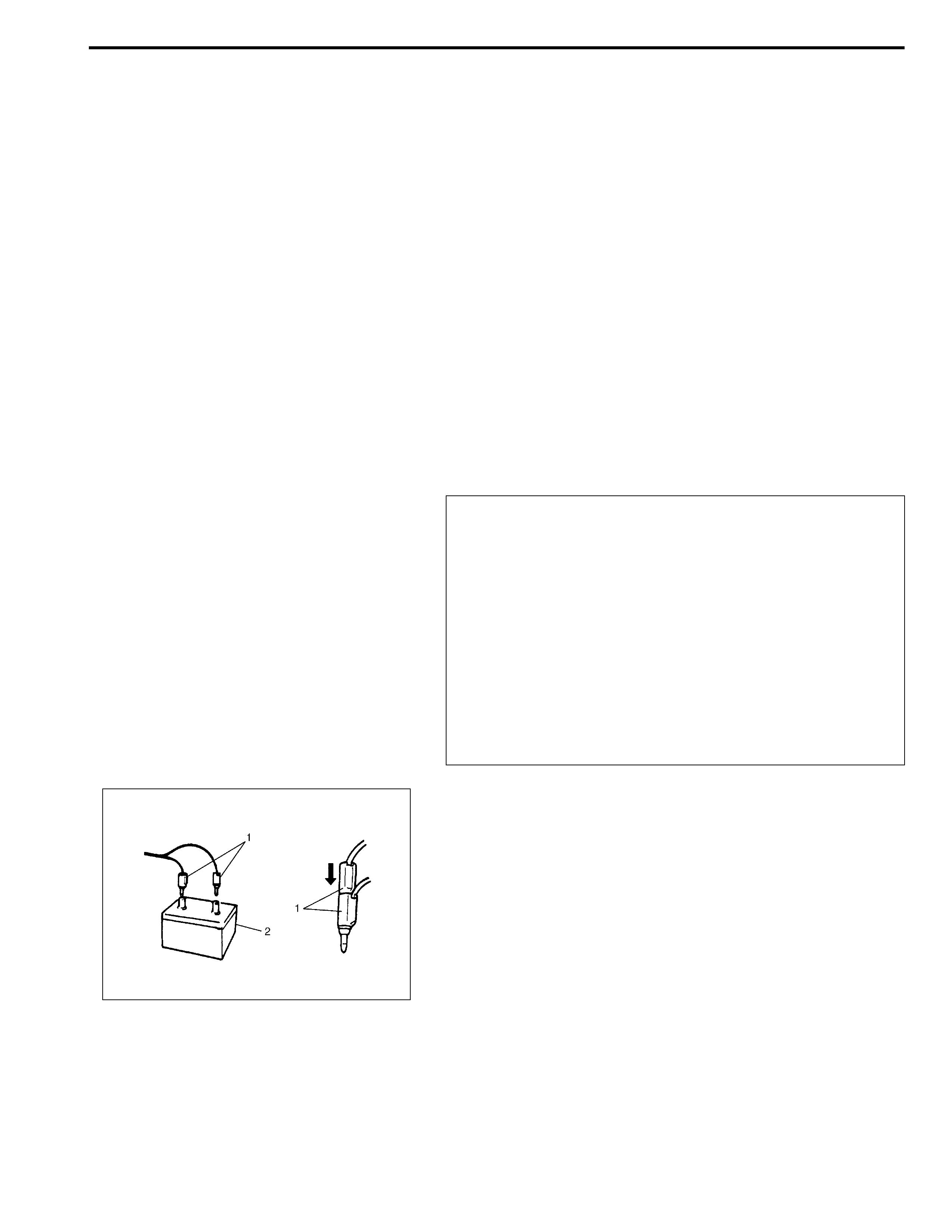
4) Short two deployment harness leads (1) together by fully
seating one banana plug into the other.
NOTE:
If faulty of seat belt pretensioner connector of adapter
cable (C) is found, replace it to spare connector (special
tool).
WARNING:
Deployment harness (A) shall remain shorted and not be
connected to 12 volts vehicle battery till you are ready to
deploy air bag module or activate seat belt pretensioner.
5) Remove applicable air bag (inflator) module or seat belt pre-
tensioner as follows.
• For driver air bag (inflator) module
Remove driver air bag (inflator) module referring to “Driver
Air Bag (Inflator) Module” in Section 3C.
• For passenger air bag (inflator) module
Remove passenger air bag (inflator) module referring to
“Passenger Air Bag (Inflator) Module” in this section.
• For seat belt pretensioner
Remove seat belt referring to “Front Seat Belt Assembly” in
Section 10.
6) Set air bag (inflator) module or seat belt pretensioner as fol-
lows.
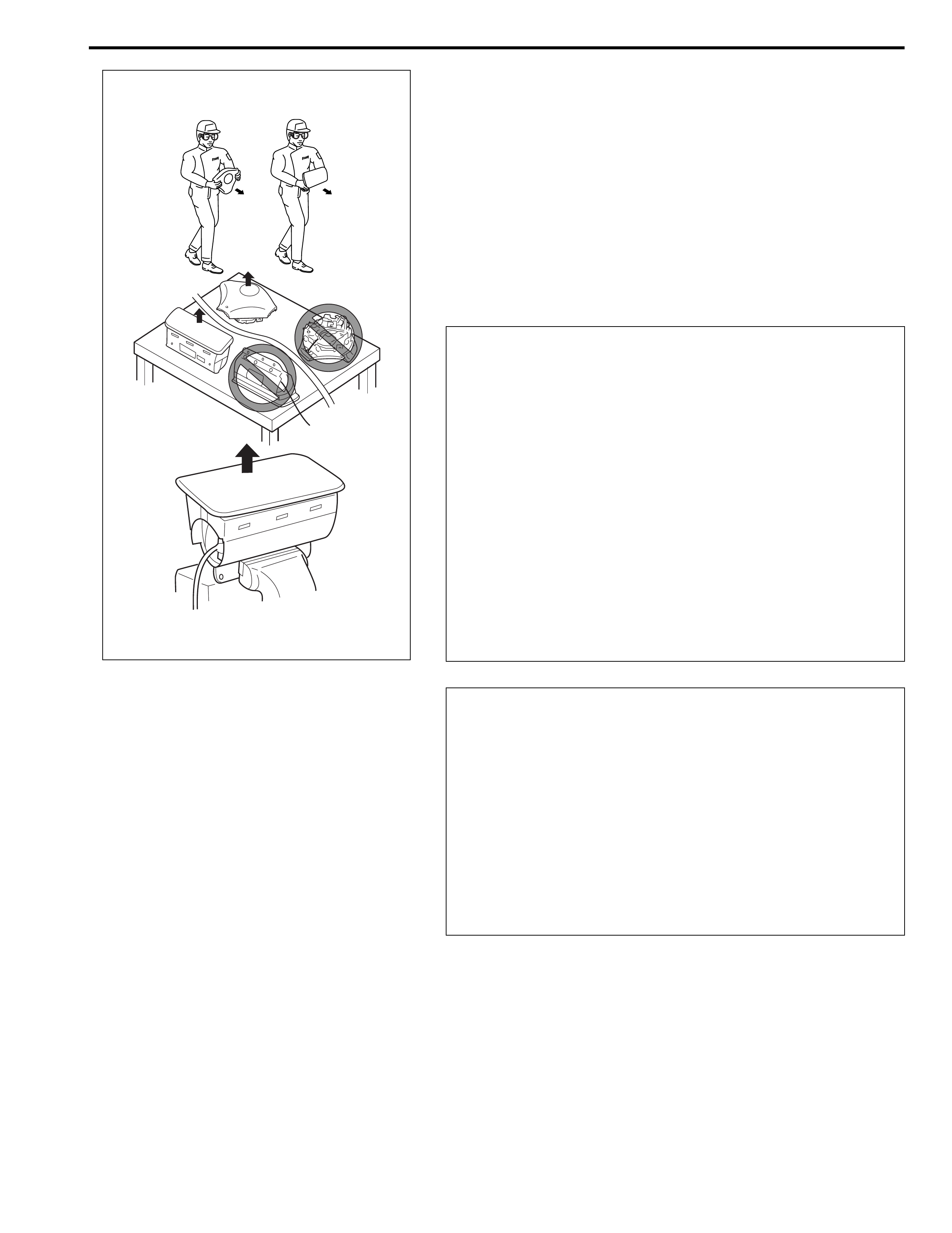
WARNING:
• For handing and storage of live air bag (inflator) mod-
ule, select place where ambient temperature below
65°C (150°F), without high humidity and away from
electric noise.
• Always carry live air bag (inflator) module with trim
cover away from you.
• When storing live air bag (inflator) module or when
leaving live air bag (inflator) module unattended on
bench or other surface, always face trim cover up and
away from surface. This is necessary so that free
space is provided to allow air bag (inflator) module to
expand in the unlikely event of accidental deployment.
Failure to follow procedures may result in personal
injury.
WARNING:
• For handing and storage of seat belt pretensioner,
select place where ambient temperature below 65°C
(150°F), without high humidity and away from electric
noise.
• Never carry seat belt pretensioner by wire or connec-
tor of seat belt pretensioner.
• When placing a live seat belt pretensioner on the work-
bench or some place like that, be sure not to put some-
thing on seat belt pretensioner.
Otherwise, personal injury may result.
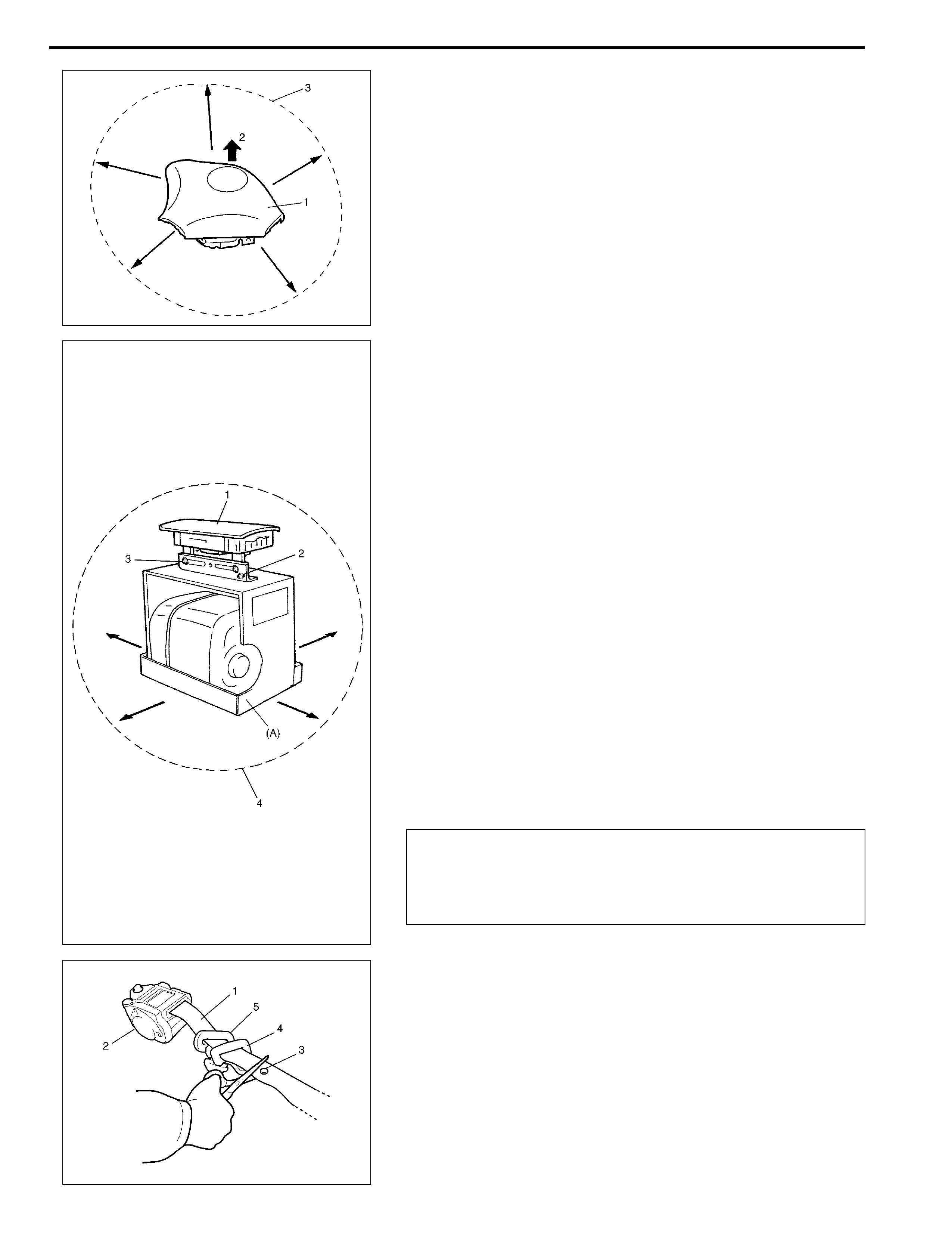
a) For driver air bag (inflator) module
i) Clear space (3) on ground about 185 cm (6 ft) in diameter
where driver air bag (inflator) module (1) for deployment.
Paved, outdoor location where there is no activity is pre-
ferred. If outdoor location is not available, space on shop
floor where there is no activity and provide sufficient venti-
lation. Ensure no loose or flammable objects are within
deployment area.
ii) Place driver air bag (inflator) module (1) with its vinyl trim
cover facing up (2) on ground in step i).
b) For passenger air bag (inflator) module
i) Clear space (4) on ground about 185 cm (6 ft) in diameter
where passenger air bag (inflator) module (1) for deploy-
ment. Paved, outdoor location where there is no activity is
preferred. If outdoor location is not available, space on
shop floor where there is no activity and provide sufficient
ventilation. Ensure no loose or flammable objects are
within deployment area.
ii) Place deployment fixture (A) on ground in step i).
Special tool
(A) : 09932-75041
iii) Fill plastic reservoir in deployment fixture (A) with water or
sand. This is necessary to provide sufficient stabilization
of fixture during deployment.
iv) Attach passenger air bag (inflator) module (1) in deploy-
ment fixture (A) securely using mounting attachment,
hold-down bolts & nuts (2) and M8 bolts & nut (3).
c) For seat belt pretensioner
i) Cut webbing (1) at tongue plate stopper (3) of seat belt
pretensioner (2) side as shown.
ii) Remove tongue plate (4) and shoulder anchor (5) from
webbing.
NOTE:
Make sure that deploying direction faces as shown in fig-
ure against mounting attachment.
CAUTION:
Be sure to use M8 size and 7T strength bolt for fixing
passenger air bag (inflator) module (1) to deployment fix-
ture (A).
NOTE:
Hold seat belt pretensioner (2) vertically in the same con-
dition as it is installed. Otherwise, webbing can’t be
pulled out.
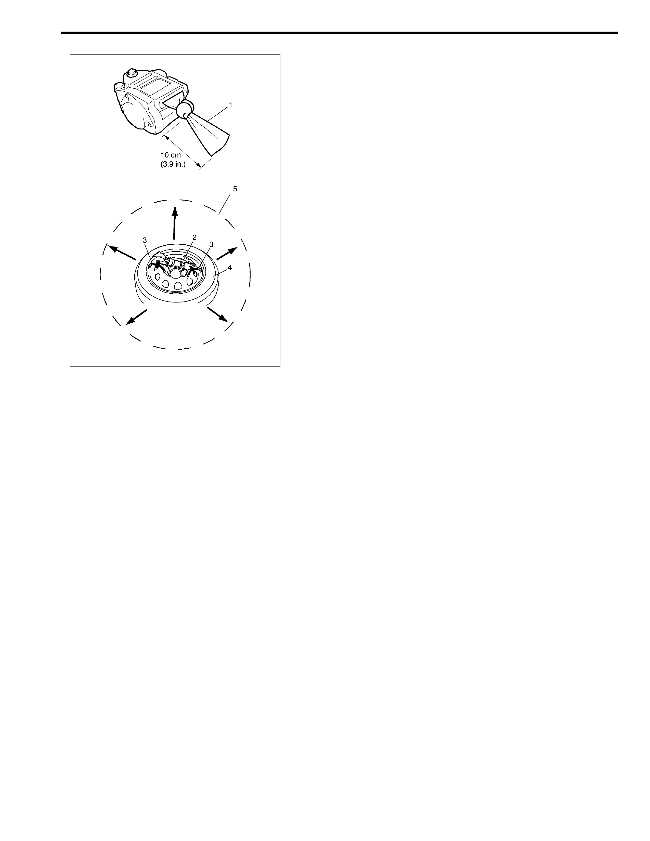
iii) Tie webbing (1) tightly at 10 cm (3.9 in.) from cutting edge
as shown.
iv) Tie seat belt pretensioner (2) with wire harness (3) to
wheel-installed tire (4) as shown.
Wire harness specification
Stripped wire harness section 1.25 mm2 (0.0019 in.2) or
more (Stripped wire harness diameter 1.25 mm (0.05 in.)
or more)
v) Clear space (5) on ground about 185 cm (6 ft) in diameter
where seat belt pretensioner (2) is to be activated. Paved,
outdoor location where there is no activity is preferred. If
outdoor location is not available, space on shop floor
where there is no activity and provide sufficient ventilation.
Ensure no loose or flammable objects are within activation
area.
vi) Place wheel-installed tire (4) with seat belt pretensioner
(2) on ground in step v).
NOTE:
Wind wire harness (3) around at least 3 times.
7) Stretch deployment harness (A) from air bag (inflator) mod-
ule or seat belt pretensioner to its full length 10 m (33 ft).
Special tool
(A) : 09932-75031
8) Place 12 volts vehicle battery (1) near shorted end of deploy-
ment harness (A).
9) Verify that area around air bag (inflator) module or seat belt
pretensioner is clear of all people and loose or flammable
objects.
10) Connect adapter cable (B) or (C) as follows.
Special tool
(B) : 09932-76510
(C) : 09932-78332
a) For driver air bag (inflator) module
Verify that driver air bag (inflator) module is resting with its
vinyl trim cover facing up, and connect adapter cable (B) to
driver air bag (inflator) module.
b) For passenger air bag (inflator) module
Verify that passenger air bag (inflator) module is firmly and
properly secured on deployment fixture (special tool), and
connect adapter cable (C) to passenger air bag (inflator)
module.
c) For seat belt pretensioner
Connect adapter cable (C) to seat belt pretensioner.
11) Connect adapter cable (B) or (C) to deployment harness (A)
connector and lock connectors with lock slider.
12) For seat belt pretensioner
a) Pile 2 wheel-installed tires (2) on top of tire with seat belt
pretensioner (3), and tie them with wire harness (4) as
shown.
Wire harness specification
Stripped wire harness section 1.25 mm2 (0.0019 in.2) or
more (Stripped wire harness diameter 1.25 mm (0.05 in.)
or more)
b) Drape blanket (5) over those tires.
NOTE:
Wind wire harness around at least 2 times.
[A]: For driver air bag (inflator) module
[B]: For passenger air bag (inflator) module
[C]: For seat belt pretensioner
13) Notify all people in immediate area that you intend to deploy/
activate air bag (inflator) module or seat belt pretensioner.
14) Separate two banana plugs (1) on deployment harness.
15) Connect deployment harness to 12 volts vehicle battery (2).
This will immediately deploy or activate air bag (inflator)
module or seat belt pretensioner.
16) Disconnect deployment harness from 12 volts vehicle bat-
tery (2) and short two deployment harness leads together by
fully seating one banana plug into the other.
NOTE:
• When air bag (inflator) module deploys and seat belt
pretensioner activates, rapid gas expansion will create
substantial report. Wear suitable ear protection. Notify
all people in immediate area that you intend to deploy
air bag (inflator) module or activate seat belt preten-
sioner and suitable ear protection should be worn.
• When driver air bag (inflator) module deploys, driver
air bag (inflator) module may jump about 30 cm (1 ft)
vertically. This is normal reaction to force of rapid gas
expansion inside of drive air bag (inflator) module.
• After air bag (inflator) module has been deployed, sur-
face of air bag (inflator) may contain powdery residue.
This powder consists primarily of cornstarch (used to
lubricate bag (inflator) as it inflates) and byproducts of
chemical reaction.
WARNING:
• Do not place deployed air bag (inflator) module and
activated seat belt pretensioner near any flammable
objects.
• Do not apply water, oil, etc. to deployed air bag (infla-
tor) module and activated seat belt pretensioner.
• Wait for about 30 minutes before touching any metal
surface of air bag (inflater) module or seat belt preten-
sioner module. Disregarding these precautions may
cause fire or personal injury.
Failure to follow procedures may result in fire or per-
sonal injury.
17) In the unlikely event that air bag (inflator) module or seat belt
pretensioner did not deploy/activate after following these pro-
cedures, proceed immediately with Step 23) through 26). If
air bag (inflator) module or seat belt pretensioner did deploy
or activate, proceed with Steps 18) through 22).
18) Put on pair of shop gloves to protect your hands from possi-
ble irritation and heat when handling deployed air bag (infla-
tor) module or activated seat belt pretensioner.
19) Disconnect adapter cable (special tool) from air bag (inflator)
module or seat belt pretensioner as soon as possible. This
will prevent adapter cable (special tool) from damage due to
possible contact with hot air bag (inflator) module or hot seat
belt pretensioner.
20) Check adapter cable connector as follows.
a) For air bag (inflator) module
Air bag (inflator) module connector of adapter cable (spe-
cial tool) are designed to be reused. However they should
be inspected for damage after deployment and replaced if
necessary.
b) For seat belt pretensioner
Seat belt pretensioner connector of adapter cable (special
tool) must be replaced to spare connector (special tool).
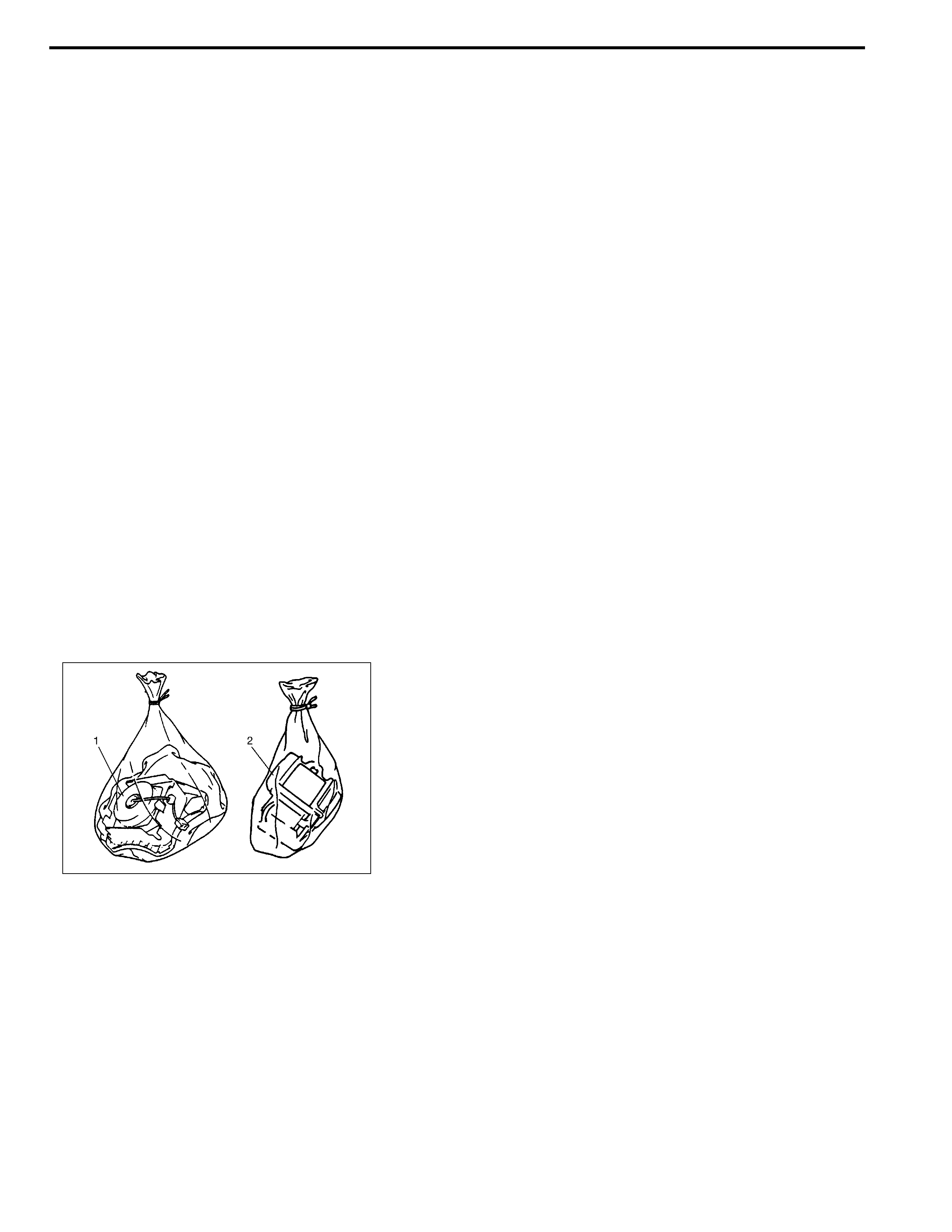
21) Dispose of deployed air bag (inflator) module (1) or activated
seat belt pretensioner (2) through normal refuse channels
after it has cooled for at least 30 minutes and tightly seal air
bag (inflator) module (1) or seat belt pretensioner (2) in
strong vinyl bag. (Refer to “Deployed Air Bag (Inflator) Mod-
ule and Activated Seat Belt Pretensioner Disposal” in this
section.)
22) Wash your hands with mild soap and water afterward.
23) Ensure that deployment harness has been disconnected
from 12 volts vehicle battery and that its two banana plugs
have been shorted together by fully seating one banana plug
into the other.
NOTE:
Do not reuse seat belt pretensioner connector of adapter
cable (special tool) because it will be destroyed by shock
when seat belt pretensioner is activated.
NOTE:
Remaining steps are to be followed in the unlikely event
that air bag (inflator) module did not deploy or seat belt
pretensioner did not activate.
24) Disconnect deployment harness and adapter cable from air
bag (inflator) module or seat belt pretensioner.
25) Temporarily store undeployed air bag (inflator) module or
unactivated seat belt pretensioner referring to “Service Pre-
cautions” in this section for details.
26) Contact your local distributor for further assistance.
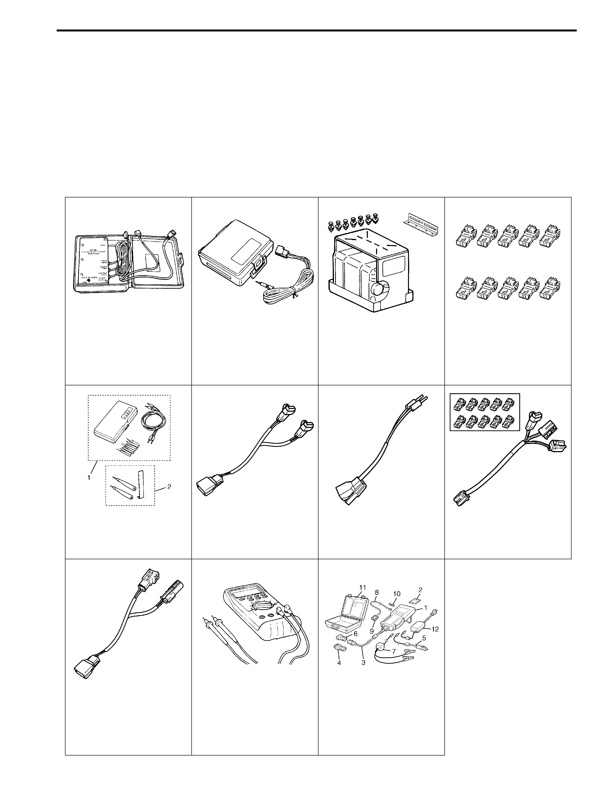
Special Tool
09932-75010 09932-75031 09932-75041 09932-75411
Air bag driver/passenger
load tool
Air bag deployment har-
ness
Passenger air bag (infla-
tor) module deployment
fixture
Spare connector (See
NOTE “A”.)
09932-76010 09932-76510 09932-78310 09932-78332
Connector test adapter
set (See NOTE “B”.)
Adapter cable Adapter cable Adapter cable
09932-78340
Adapter cable Digital multimeter
(See NOTE “C” and
WARNING.)
TECH 2 scan tool (See
NOTE “D”.)

WARNING:
Be sure to use the specified digital multimeter. Otherwise, air bag deployment or personal injury may
result.
NOTE:
• “A” : These connectors are spares for adapter cable (09932-78332).
• “B” : This set includes the following items.
1. Connector test adapter kit (09932-75020),
2. Connector test adapter & shorting bar release tool (09932-76020)
• “C” : Digital multimeter specification : The maximum test current is 10 mA or less at the minimum
range of resistance measurement.
• “D” : This kit includes the following items.
1. Tech 2, 2. PCMCIA card, 3. DLC cable, 4. SAE 16/19 adapter, 5. Cigarette cable,
6. DLC loopback adapter, 7. Battery power cable, 8. RS232 cable, 9. RS232 adapter,
10. RS232 loopback connector, 11. Storage case, 12. Power supply