
SECTION 3A - FR ONT END ALIGNMENT
1. GENERAL DESCRIPTION
1.1 TO E SETTIN G
1.2 CAMBER
1.3 ALIGNMENT SERVICE
DATA (REFERENCE)
2. DIAGNOSIS
2.1 DIAGNOSIS TABLE
2.2 PRELIMINARY CHECKS PRIOR TO
ADJUSTING FRONT ALIGNMENT
2.3 TOE ADJUST MENT
2.4 CAM BER AND CASTER CHECK
AND ADJUSTMENT
2.5 STEERING ANGLE CHECK
AND ADJUSTMENT
2. 6 S ID E SL IP ( R EFE R ENCE)
1. GENERAL DESCRIPTION
Front alignment refers to the angular relationship between the front wheels, the front suspension attaching
parts and the ground. Generally, the only adjustment required for front alignment is toe setting.
Camber a nd caster can’t be ad justed. Therefore, should camber or caster be out of specification due to the
damage caused by haza rdous r oad condi tions or collision, it should b e determ ined w hether the damage is in
the body or in the suspension. If the body is damaged, it should be repaired and if the suspension is dam-
aged, it should be replaced.
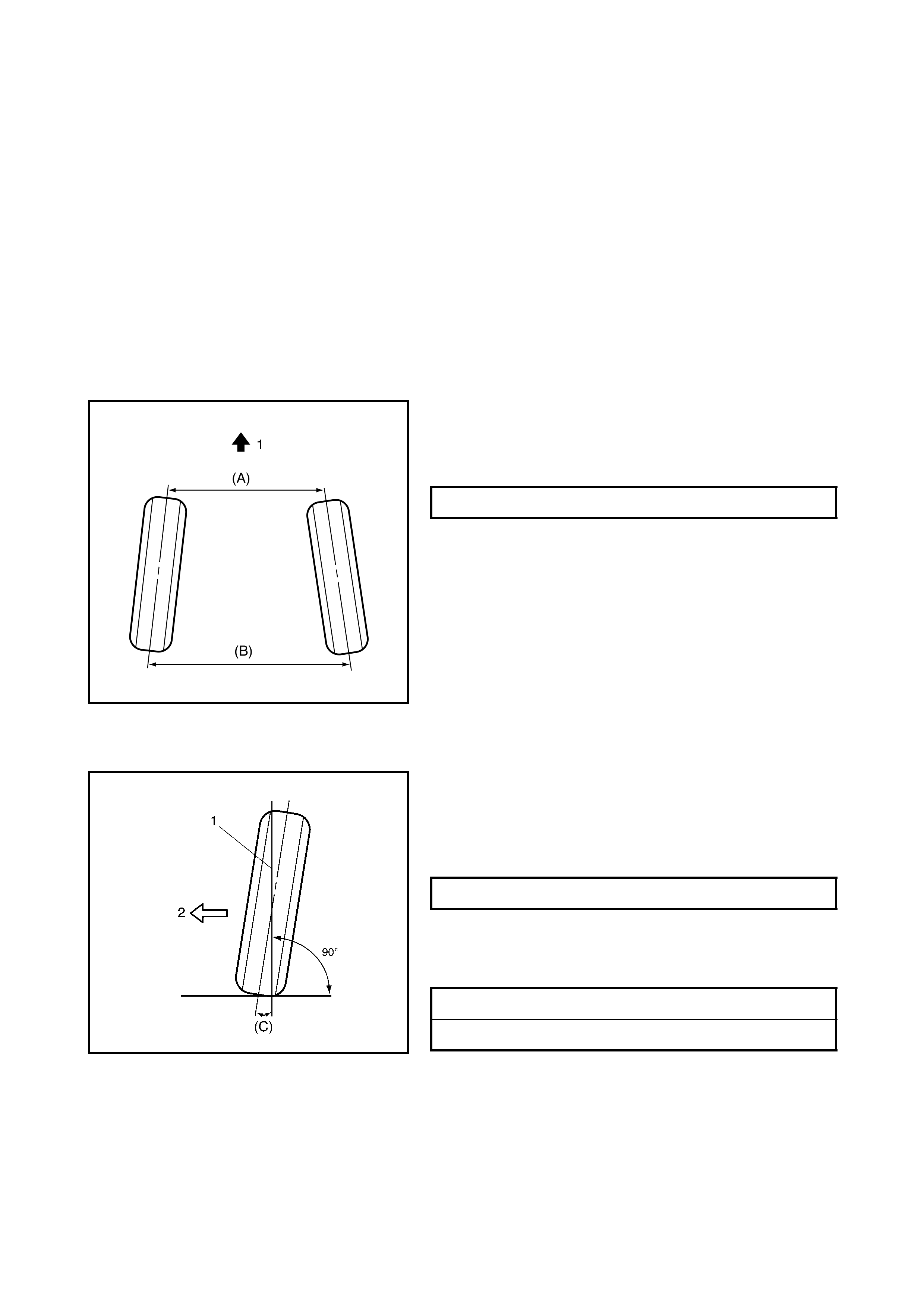
1.1 TOE SETTING
Toe is the turning in or out of the front wheels [A] (viewed
from abov e). T he purpose of a t oe specification is to ensure
parallel rolling of the front wheels (Excessive toe-in or toe-
out may increase tyre wear).
NOTE: Toe in v al ue was m easured by using a toe in gauge.
For adjusting toe setting, refer to 2.3 TOE ADJUSTMENT
in this Section.
1.2 CAMBER
Camber is the tilting of the front wheels from the vertical
(1), as viewed from the front of the vehicle. When the
wheels tilt outward (2) at the top, the camber is positive.
W hen the wheels tilt inward at the top, the cam ber i s nega-
tive. The amount of tilt is measured in degrees (C).
1.3 ALIGNMENT SERVICE DATA
(REFERENCE)
TOE IN (B) – (A) 0 ± 2 mm
CAMBER (C) 0° ± 1°
CASTER 3° 39’ ± 2°
KINGPIN INCLINATION 12° 15’ ± 2°
2. DIAGNOSIS
2.1 DIAGNOSIS TABLE
For the details, refer to Section 3 STEERING, SUSPENSION, WHEELS AND TYRES.
2.2 PRELIMINARY CHECKS PRIOR TO ADJUSTING FRONT ALIGNMENT
Steering and vibration complaints are not always the result of improper alignment. An additional item to be
checked is the possibi lity of tyre lead due to worn or improperl y manufactured tyres. “Lead” is the deviation of
the vehicle from a straight path on a level road without h and pressure on the steering wheel. For the proce-
dure for determining the presence of a tyre lead problem refer to Section 3 STEERING, SUSPENSION,
WHEELS AND TYRES. Before making any adjustment affecting toe setting, the following checks and inspec-
tions should be made to ensure correctness of alignment readings and alignment adjustments :
1. Check all tyres for correct inflation pressu res and approximately the same tread wear.
2. Check f or loose ball joints. Check tie rod ends; if e xcessiv e looseness is noted, it must be corrected bef ore
adjusting.
3. Check for run-ou t of wheels and tyres.
4. Check v ehi cle trim heights; if out of limits and a correction is to be made, it m ust be made bef ore adjusting
toe.
5. Check for looseness of suspension arms.
6. C he ck for loos e or mis s ing s tabilise r ba r a tt ac h m e nt s.
7. Consideration must be given to excess loads. If this excess load is normally carried in the vehicle, it
should remain in the vehicle during alignment ch ecks.
8. Consider condi tion of equipment being used to check alignme nt and fol low manufacturer's instru ctions.
9. Regardless of equipment used to check alignment, vehicle mu st be on a level surface both fore and aft
and transversely.
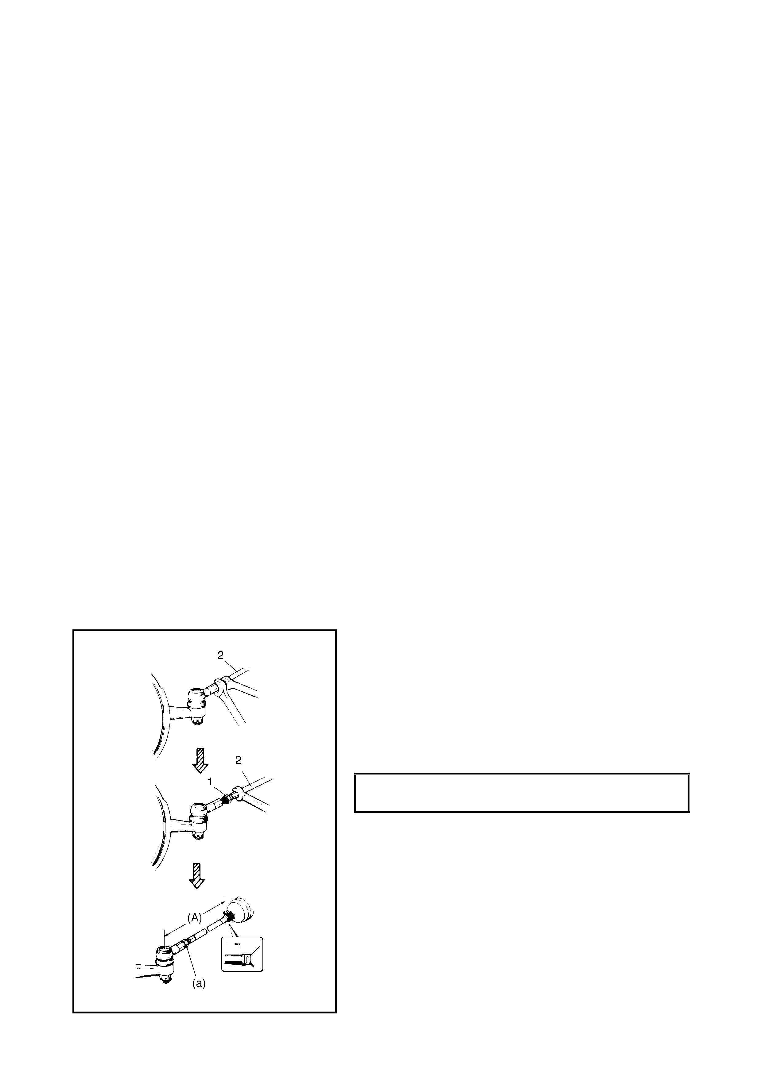
2.3 TOE ADJUSTM ENT
1. Loosen right and left tie rod end lock nuts (1) first.
2. Rot at e righ t and left tie rods (2) by the same amount to
align toe to specification. In this adjustment, right and
left tie rods (2) should become equal in length (A).
NOTE: Before rotat i ng tie rods (2) apply grease between tie
rod s and rack boots so that boo ts will not be twist ed.
3. After adjustment, tighten lock nuts (1) to specified
torque.
NOTE: Make s ure that rack boots are not twisted.
TIE ROD END LOCK NUTS
TORQUE SPECIFICATIONS (a) 45 Nm
2.4 CAMBER AND CASTER CHECK AND ADJUSTMENT
Should camber or caster be found to be out of specifications upon inspection, first locate the cause.
If there are damaged, loose, bent, dented or wor n suspensio n parts, they should be replaced.
If it is in the v ehicle body, repair it to correct specifications.
NOTE: To prevent possible incorrect reading of camber or caster, vehicle front end must be moved up and
down a few times before inspection .
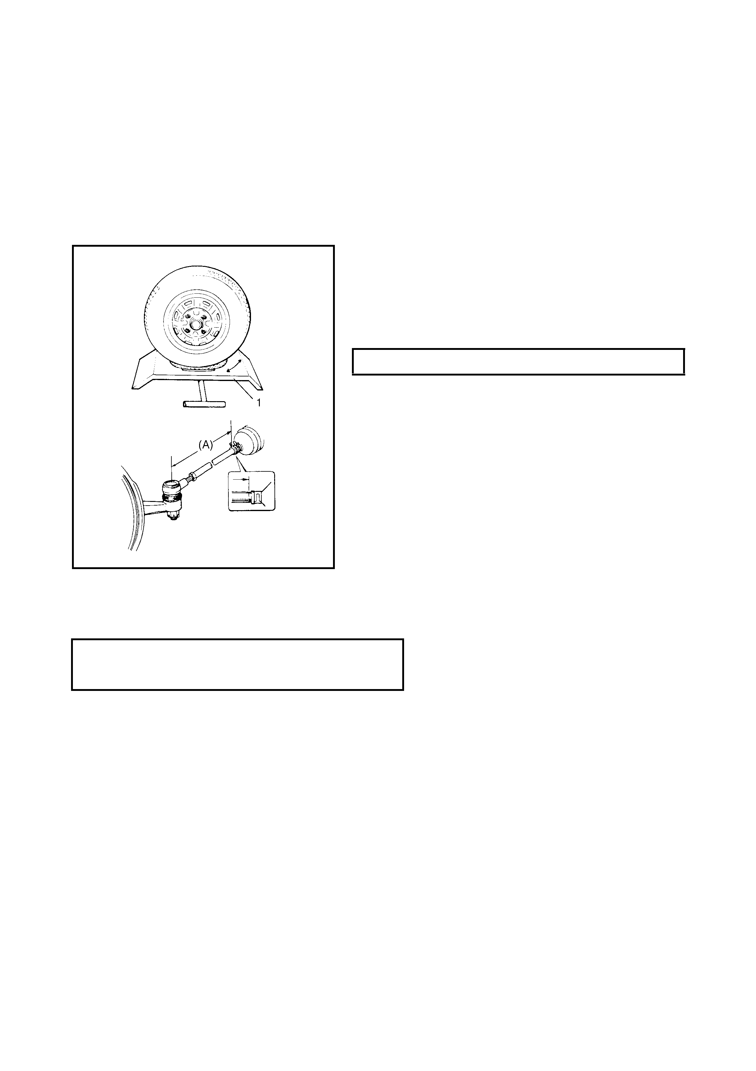
2.5 STEERING AN GLE CHECK AND ADJUSTMENT
When tie rod or tie rod end was replaced, check toe and
then also steerin g angle with turnin g radius gauge (1).
If steering angle is not correct, check if right and lef t tie rods
are equal in length (A).
NOTE: If tie rod lengths were changed to adjust steering
angle, reinspect toe-in.
2.6 SIDE SLIP (REFERENCE)
For inspecting front wheel side slip with side slip tester:
If side slip exce eds above limit, toe-in or front wheel alignment may not be correct.
STEERING ANGLE - INSI DE 35.1° ± 3°
SIDE SLIP LIMIT IN
OUT 2 mm/m
1 mm/m