SECTION 3B - MANUAL RACK AND PINION
1. GENERAL DESCRIPTION
2. DIAGNOSIS
2.1 DIA GNOSIS TA BLE
2.2 STEERING RACK BOOT CHECK
2.3 TIE ROD END BOOTS CHECK
2. 4 STEER I N G SHAFT J OIN T CHECK
2.5 THE ROD END CHECK
2.6 STEERING WHEEL CHECK
3. ON- VEHIC LE SERVICE
3.1 LUBRICATION
3.2 TIE ROD END
Removal
Installation
3.3 MANUAL RACK AND PINIO N
ASSEMB LY (STEERING
GEAR CASE)
Removal
Installation
3.4 RACK BOOT/TIE ROD
Removal
Installation
3.5 S TEERING RACK PLUNGER
Removal
Inspection
Installation
3.6 STE ERING P INION
Removal
Inspection
Installation
3.7 STEERING RACK
Removal
Inspection
Installation
3.8 PINION BEARING
Removal
Installation
4. REQUIRED SERVICE MATERIAL
5. SPECIAL TOOLS
WARNING:
For vehicles equipped with a Airbag System
• Ser vice on o r around airbag system components or wi ring must be performed only by an autho-
rised Holden retailer. Please observe all WARNINGS and CAUTIONS in SECTION 10B AIRBAG and
PRECAUTIONS, AIRBAG SYSTEM COMPONENTS and WIRING LOCATION VIEW in Section 10B
AIRBAG b efore p erform ing serv ice on or around airbag system comp onents o r wiring. Failure to
follow WARNINGS co uld result in unintended activation of the system or could render the system
inoperative. Either of these two conditions may result in severe injur y.
• Technical service work must be started at least 90 seco nds after the ignition switch is turned to
the “LOCK” position and the negative cable is disconn ected from the battery. Otherwise , the sys-
tem may be de ployed by reserve energy in the Sensing and Diagno stic Module (SDM).
NOTE:
All steering gear fasteners are important attaching parts that could affect the performance of vital
parts an d systems, and /or could resul t in major repair expense. They must be replaced with one of
the same par t number or with an equivalent part if replacement becom es ne cessar y. Do not use a
replac ement par t of lesser qu ality or substitute design. Torque values must be used as specified
during reas sem bly to assure correct rete ntion of these par ts.
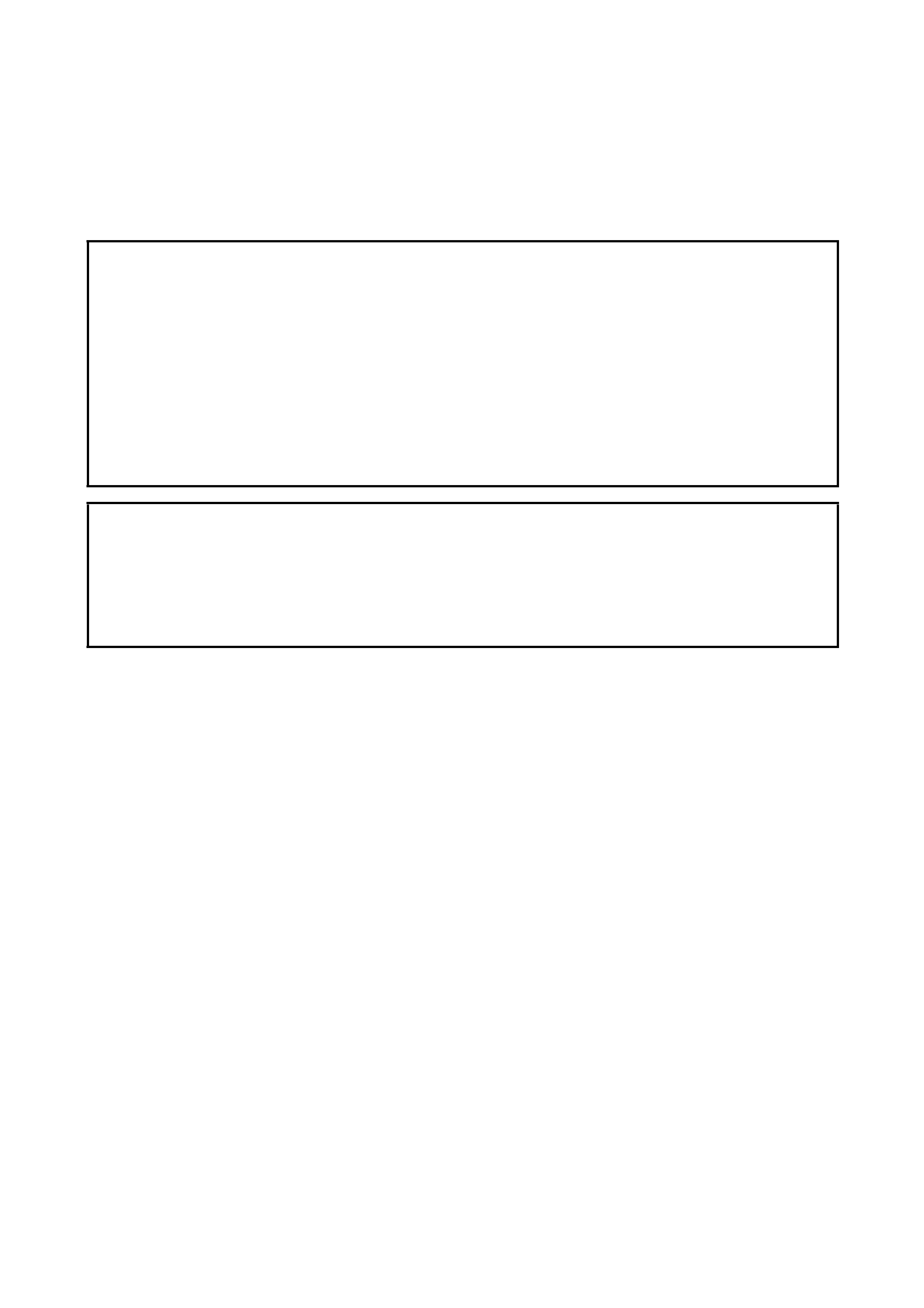
1. GENERAL DESCRIPTION
Legend
1. Steering wheel 5. Stee ring gear case 9. Tie rod end castle nut
2. Steering shaf t 6. Gea r Case Bolt 10. Steeri ng knuckle
3. Shaft joint 7. T ie rod Tightening torque
4. Joint bolt 8. T ie rod end
2. DIAGNOSIS
2.1 DIAGNOSIS TABLE
Refer to Section 3 STEEING, SUSPENSION, WHEELS
AND TYRES.
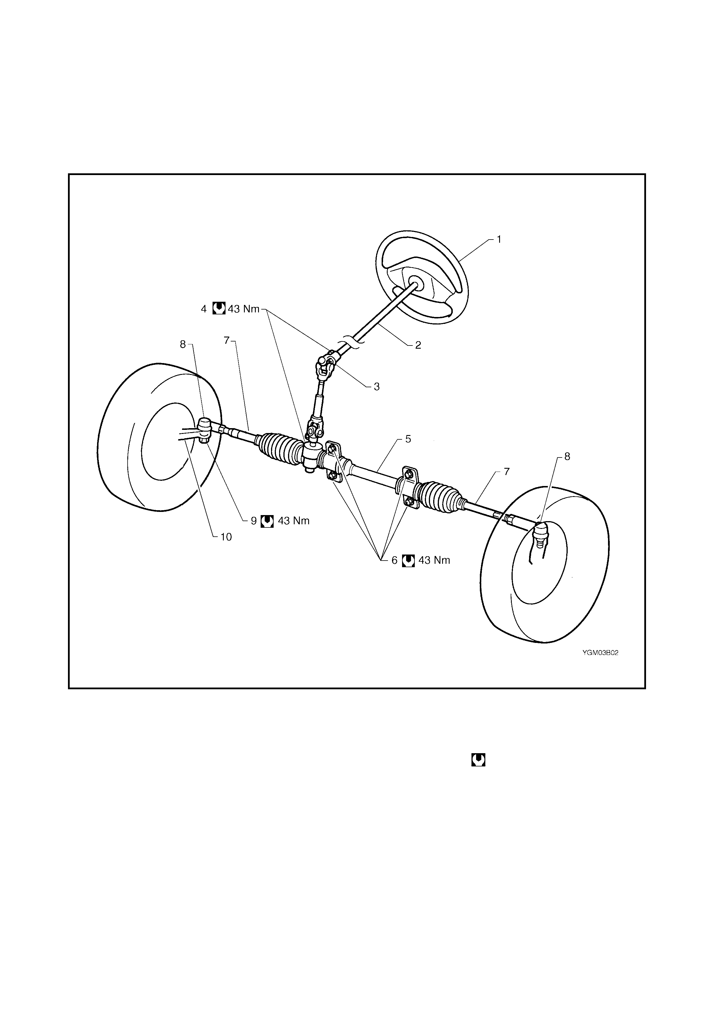
2.2 STEERING RACK BOOT CHECK
Raise vehicle on hoist.
Inspect each boot for tears. A torn boot allows entry of dust
and water which can cause wear to steer ing rack and pin-
ion, produc ing noise as well as ru st which co uld result in a
malfunct ion of the steer ing system .
If even a small tear is noted, replace boot with a new one.
Boots should be visually inspected for any damage and
tears during every periodical service at specified intervals
and w henever vehicle is hoisted for any other pur pose.
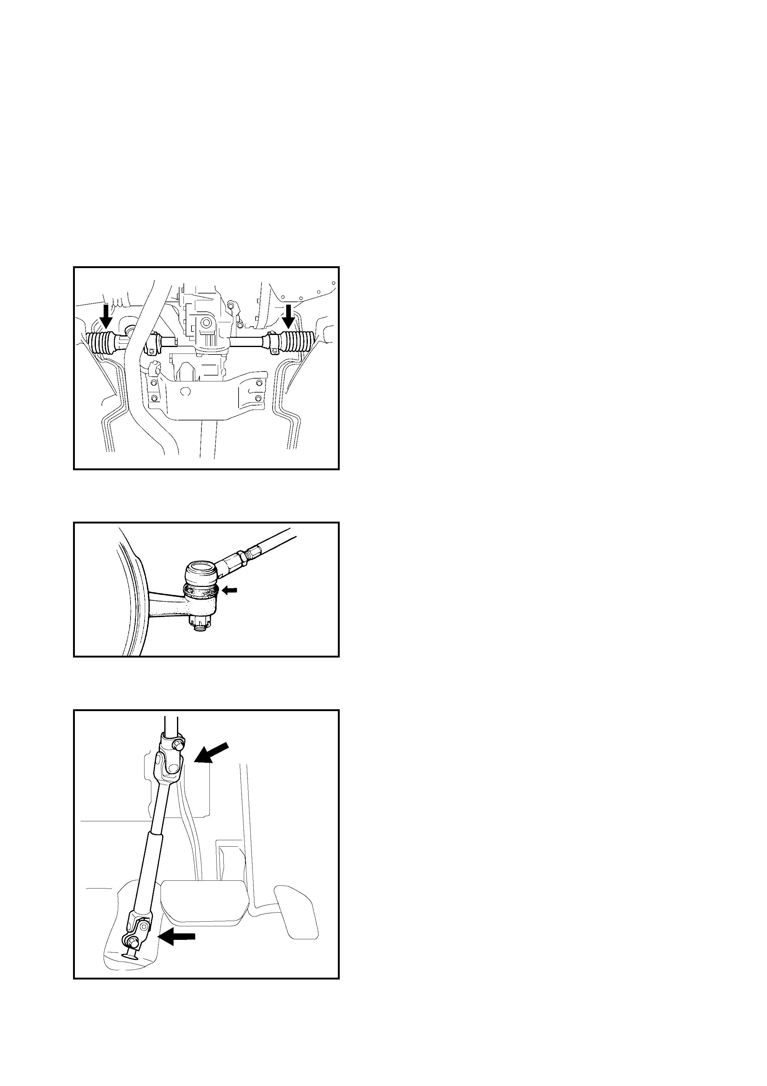
2.3 TIE ROD END BOOTS CHECK
Inspect each boot for tears. If even a small tear is noted,
replace boot with a new one.
2.4 STEERING SHAFT JOINT CHECK
Check shaft joint for wear, breakage and other damage and
replace if any defects are found.
2.5 TIE ROD END CHECK
1. Inspect for play in ball joint.
2. Inspect for play in rack end ball joint.
In either case, if found def ectiv e, replace.
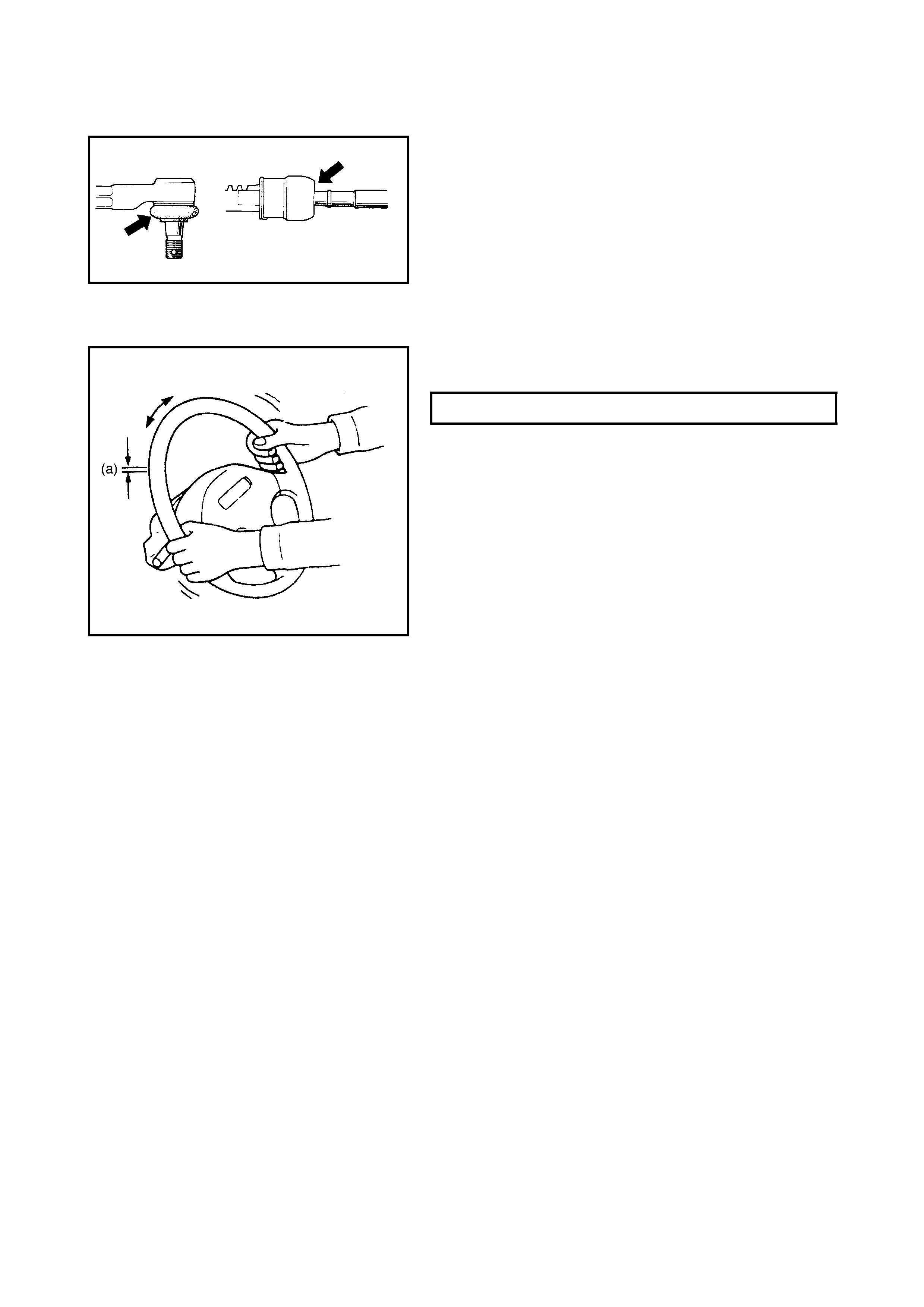
2.6 STEERING WHEEL CHECK
Check steering wheel for play and rattle, with wheels in
straight forward position and vehicle on level ground.
If stee ring wheel play is not within specification, inspect as
foll ows and replace if found defectiv e.
• Tie rod end ball stud for wear (ball stud should move
when more than 2 kg-cm torque is ap plied)
• Lower ball joint for wear
• Steering shaft joint for wear
• Steeri ng pinion or rack gear for wear or breakage
• Each part for looseness
3 . ON-VEHICLE SERVICE
3.1 LUBRICATION
When inn er parts of the steeri ng gear c ase are disassem bled, they should be washed c lean b efore rea ssem-
bly. It is recom mended to use the grease as specified be low where grease appl ication i s not in dicated in the
text.
Lithium grease: (a pplicable for –40°C ~ 130°C)
STEERING WHEEL PLAY (a) 0 - 30 mm
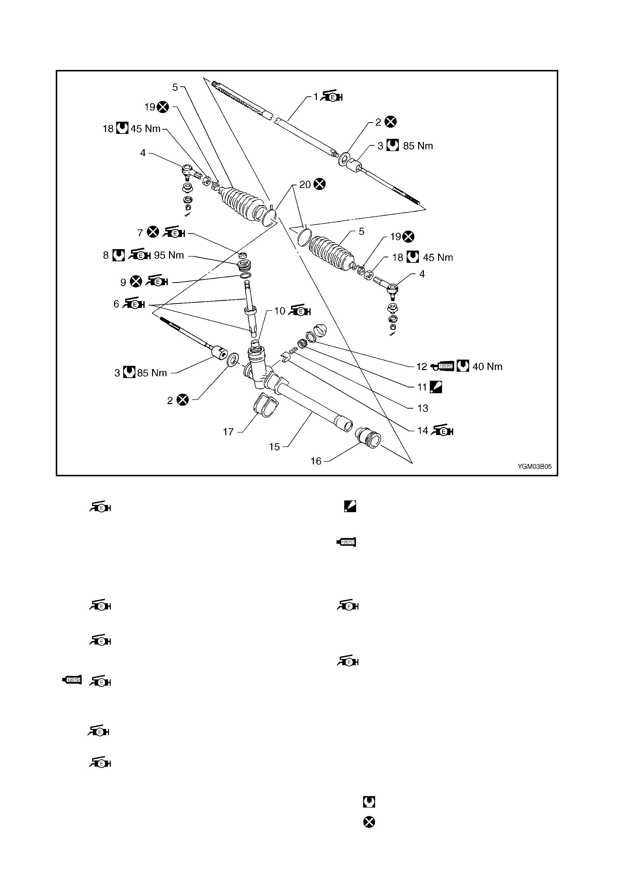
Legend
1. St eering rack
: Apply lithium grea se to teeth
surface of rack
11. Rack damper screw
: Tighten rack damper screw so that
rotation torque bec ome s as specified.
2. Tie rod lock washer 12. Rack damper screw lock nut
:Apply watertight sealant, Three Bond
No. 1207C all around threaded part of
lock nut.
3. St eering tie rod
4. T ie rod end
5. Boot 13. Ra ck plun ger spring
6. St eering pinion
Apply lithium grease to pinion shaft 14. Steeri ng rack plunger
: Apply lithium grease to
sliding part of plunger.
7. Stee ring pinion shaft oil seal
: Apply lithium grea se to o il seal lip. 15. Steeri ng gear case
: Apply lithium grease lightly to
entire surface of back bushing.
8. Pini on bearing plug
: Apply lithium grea se to ins ide of pinion
bear ing plug. 16. Steeri ng rack side mou nt
9. O-ring
: Apply lithium grease to O-ring 17. Steering pinion side mount
18. Tie rod end lock nut
10
.Steering pinion needle bearing
: Apply lithium grea se to rollers
of bearing.
19. Rack boot clip
20. Wire
Tightening torque
Do not reuse .
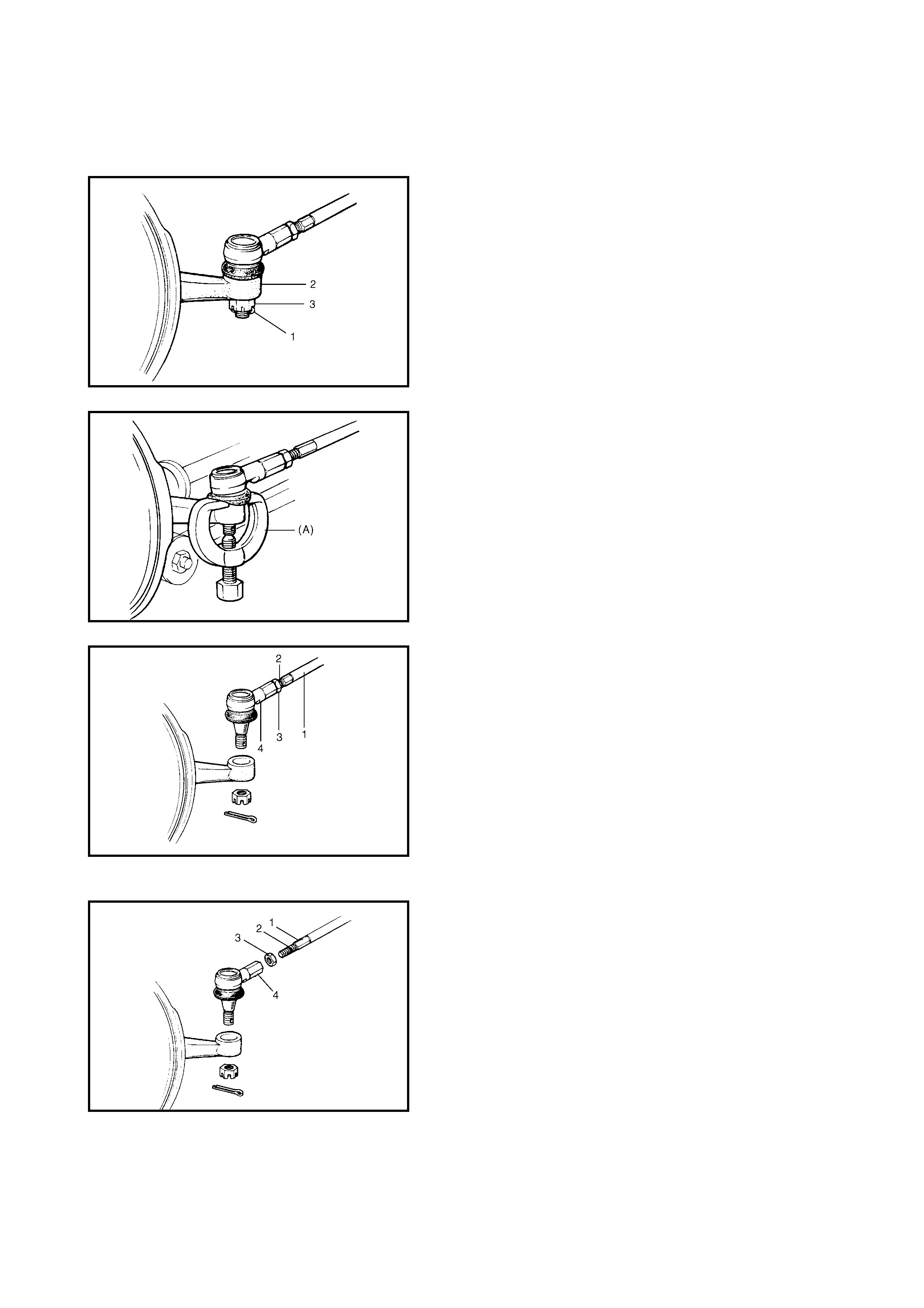
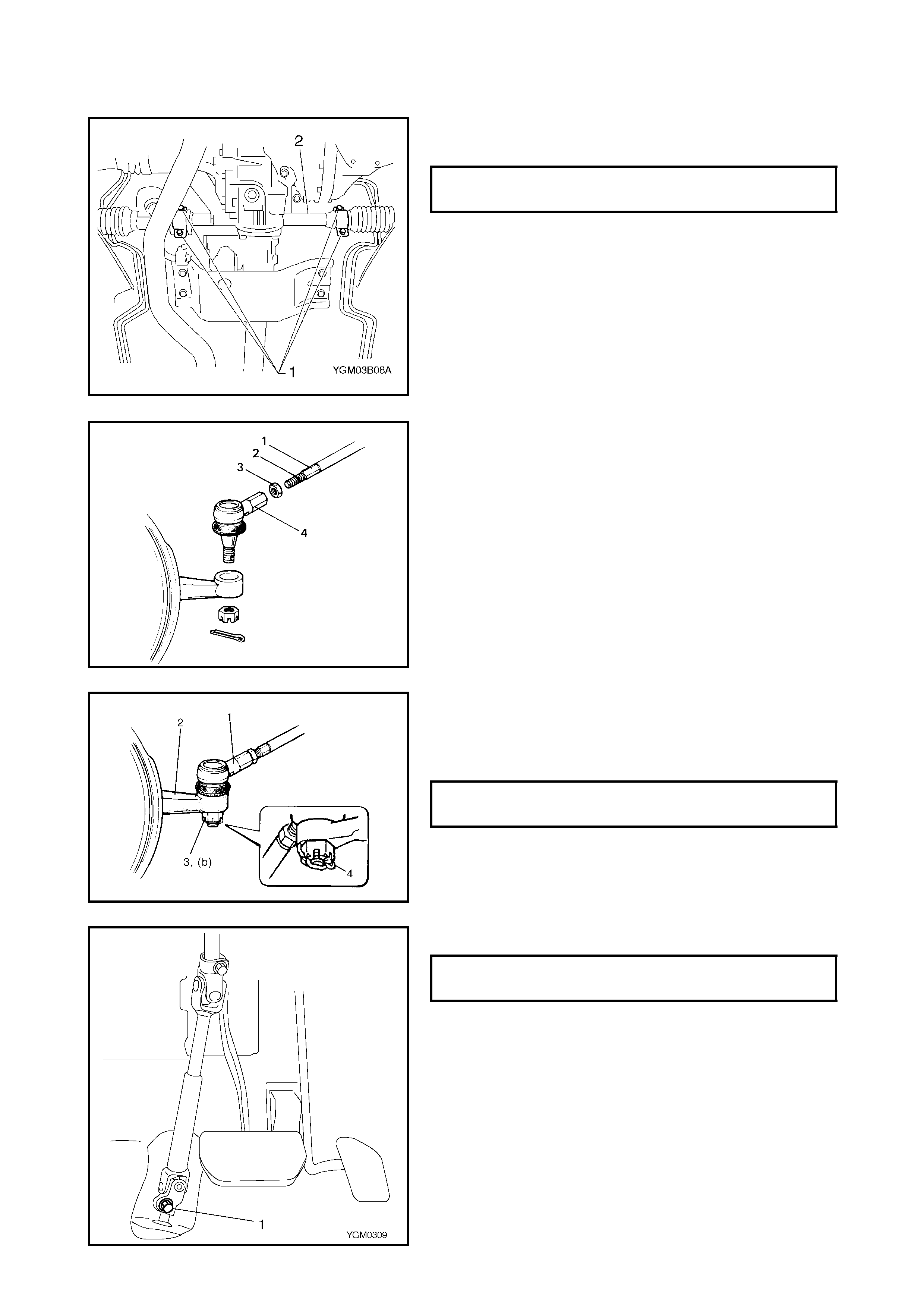
3.2 TIE ROD END
REMOVAL
1. Raise vehicle on hoist and remove wheel.
2. Remove split pin (1) and tie rod end c ast le nut (3) from
steeri ng knuckle (2).
3. Disconn ect tie rod end from knuckle, using special tool
(A) 09913-65210.
4. F or ease of adjustment after installation, make marking
(2) of tie rod end lock nut (3) position on tie rod end
thread. Then loosen lock nut and remove tie rod end
(4) from tie rod (1).
INSTALLATION
1. Install tie ro d end lock nut (3) and t ie rod end (4) to tie
rod (1). Position lock nut to marking (2) made in
removal.
2. Connect tie rod end to knuckle. Tighten castle nut (1)
until holes for split pin (2) are aligned, but only within
specified torque.
3. Bend new split pin as shown.
4. Tighten wheel nuts to specified torque and lower hoist..
5. Inspect for proper toe, refer to Section 3A FRONT END
ALIGNMENT.
6. After confir ming proper t oe, tigh ten tie rod end lock nut
to specified torque.
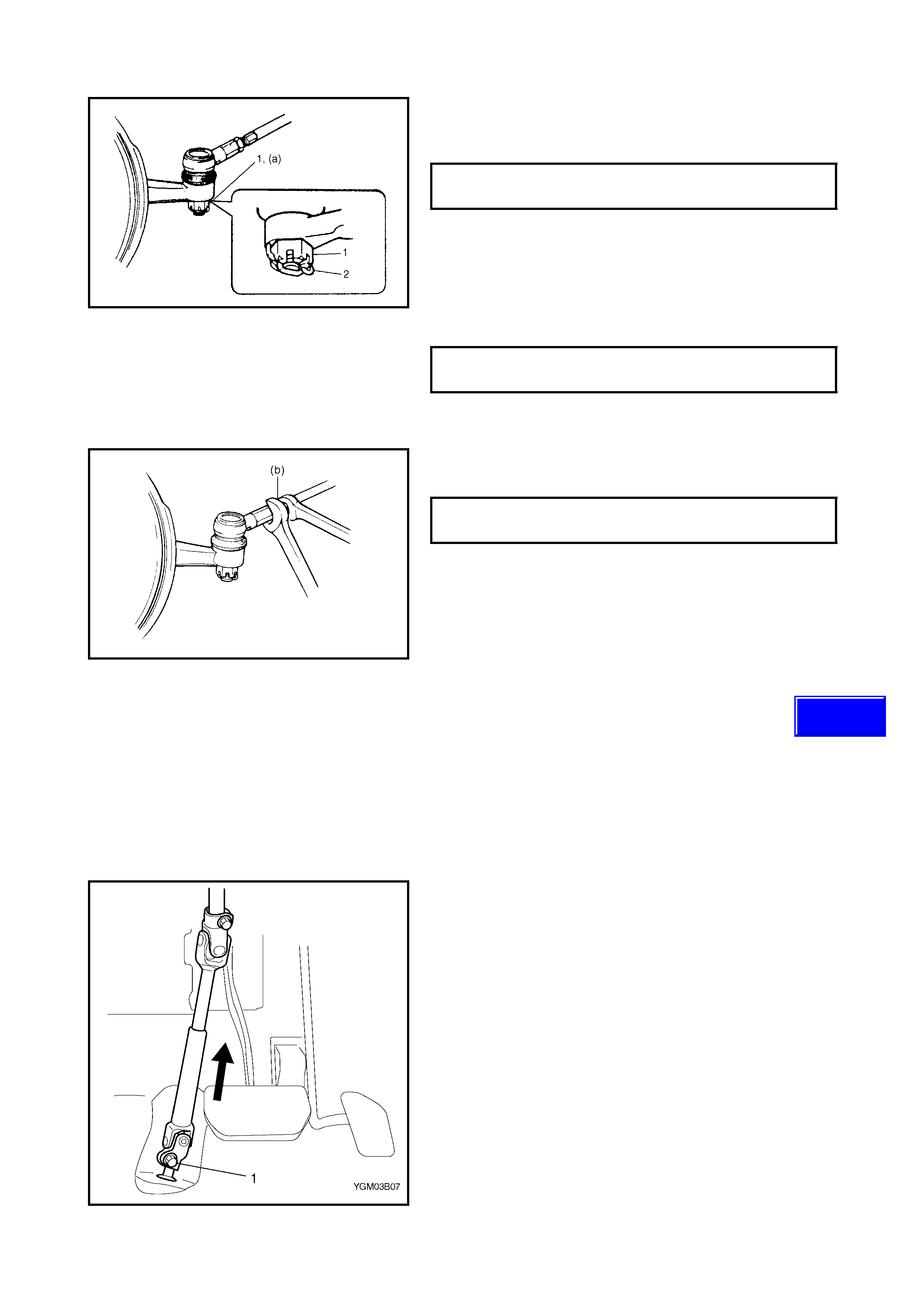
3.3 MANUAL RACK AND PINION ASSEMBLY (STEERING GEAR CASE)
REMOVAL
CAUTION: Be sure to set front wheels in straight
direction and r emove ignition key from ignition before
these steps, otherwise contact coil of airbag system
may be damaged.
1. Slide driver’s se at as far b ack as possible.
2. Remov e steering shaft joint cov er.
3. Remove steering shaft lower joint bolt (1) and discon-
nect lower joint from pinion.
CASTLE NUT
TORQUE SPECIFICATION 43 Nm
WHEEL NUT
TORQUE SPECIFICATION 85 Nm
TIE ROD END LOCK NUT
TORQUE SPECIFICATION 45 Nm
Techline
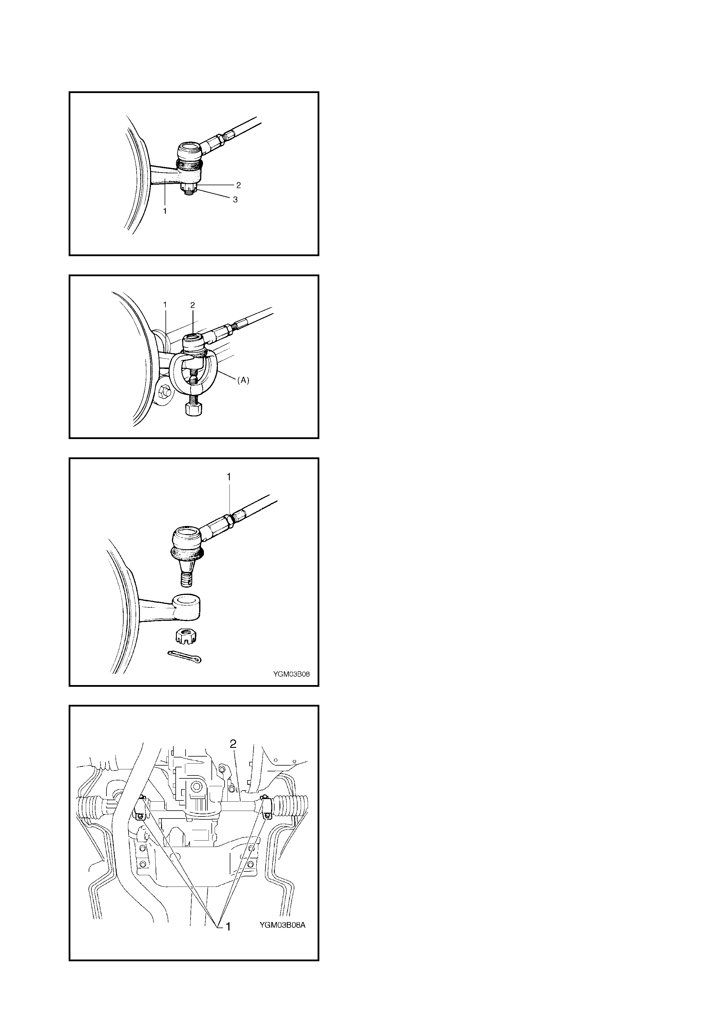
4. Hoist vehicle and remove both wheels.
5. Remove split pins (3) and tie rod castle nuts (2) from
both knuckles (1).
6. Disconnect both tie rod ends (2) from knuckles (1),
using special tool (A) 09913-65210.
7. To enable correct reassembly of each tie rod end,
make mark (1) of position of tie rod end lock nut on
each tie rod end thread.
Remov e both tie rod ends.
8. Remove steering gear case mount bolts (1) and gear
case brackets, then remove gear case (2).
INSTALLATION
1. Mount s teering g ear case (2) to body a nd tighten gear
case mo unt bolts (1) to speci fied torque.
2. Install tie rod end lock nuts (3) and tie rod ends (4) to
tie rods (1). A lig n ea ch lo ck nut to m arking (2) m ade in
removal.
3. Install both tie rod ends (1) to knuckles (2). Tighten
each castle nut (3) until holes for split pin (4) align but
are within specified torque and then bend new split pin
as shown.
4. Be sure that st eering whee l and brake discs (right and
left) are al l straight a head drivin g state and then i nser t
steeri ng lower joint into steering pinion shaft.
5. Tighten steer ing shaf t joint bolt (1 ) to specified torque.
GEAR CASE MOUNT BOLT
TORQUE SPECIFICATION 25 Nm
CASTLE NUT
TORQUE SPECIFICATION 43 Nm
STEERING SHAFT JOINT BOLT
TORQUE SPECIFICATION 25 Nm
6. Reinstall cover (1) removed previously to steering shaft
joint.
7. Install both wheels and tighten wheel nuts to specified
torque.
8. Lower hoist.
9. Check toe setting. Adjust as required refer to
Section 3A FRONT END ALIGNMENT.
10. Tighten both tie rod end lock nuts to specified torque.
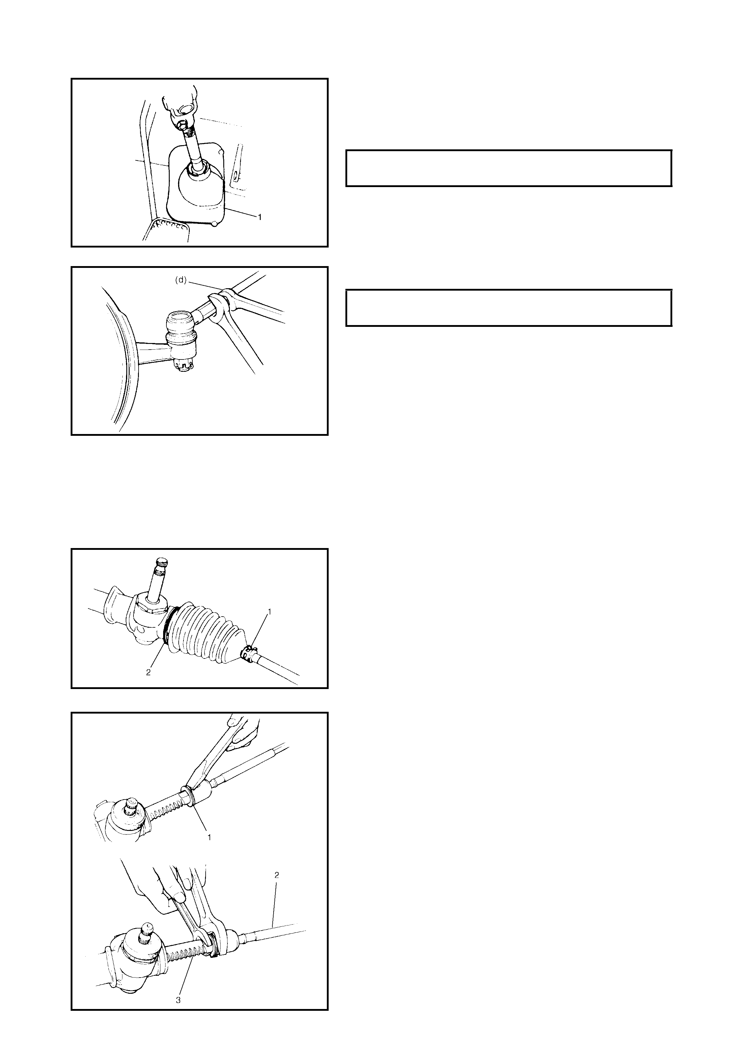
3.4 RACK BOOT/TIE ROD
REMOVAL
1. Remove steering gear case, refer to 3.3 MANUAL
RACK AND PINION ASSEMBLY REMOVAL in this
Section.
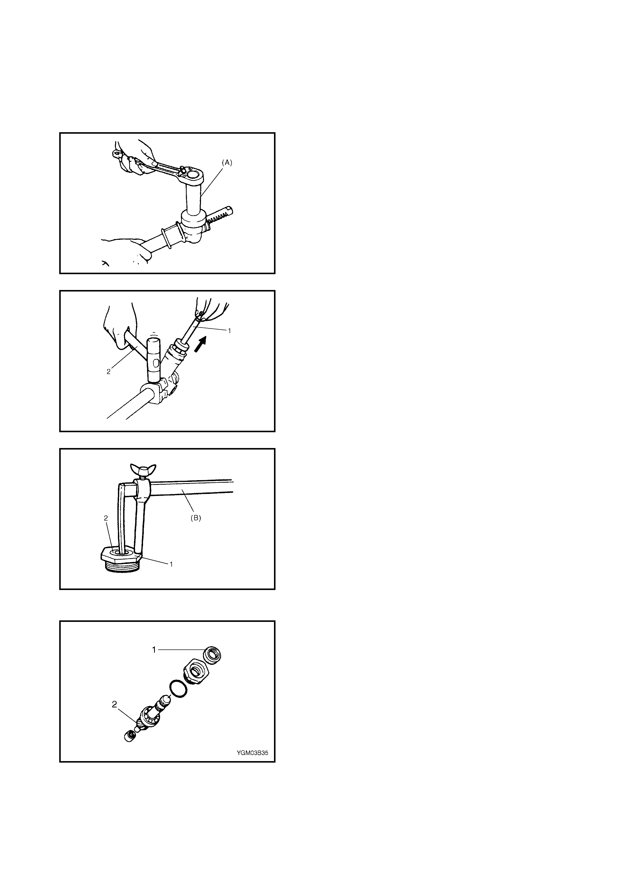
2. Remove boot wire (2) and clip (1).
3. Remove boot from tie rod.
4. Straighten bent part of tie rod lock washer (1) and
remove tie ro d (2) from rack (3).
WHEEL NUT
TORQUE SPECIFICATION 85 Nm
TIE ROD END LOCK NUT
TORQUE SPECIFICATION 45 Nm
INSTALLATION
1. Install new tie rod lock washer (2) and tie rod ball nut
(3) to rack (1).
NOTE: For correct installation of tie rod lock washer, refer
to the figure.
2. Tighten tie rod inside ball nut (3) to specified torque (a).
3. Bend new lock washer to tie rod ball nut side as shown.
4. Position boot properly in grooves of gear case or rack
side mount (2) and tie rod (4) and clamp it with wire (1)
and clip (3).
Always use new wire which should be wrapped twice
around the boot and the ends twisted securely
together. The twisted ends should be bent back neatly
against the wire.
Check to ensure that boots are free from twists and
dents.
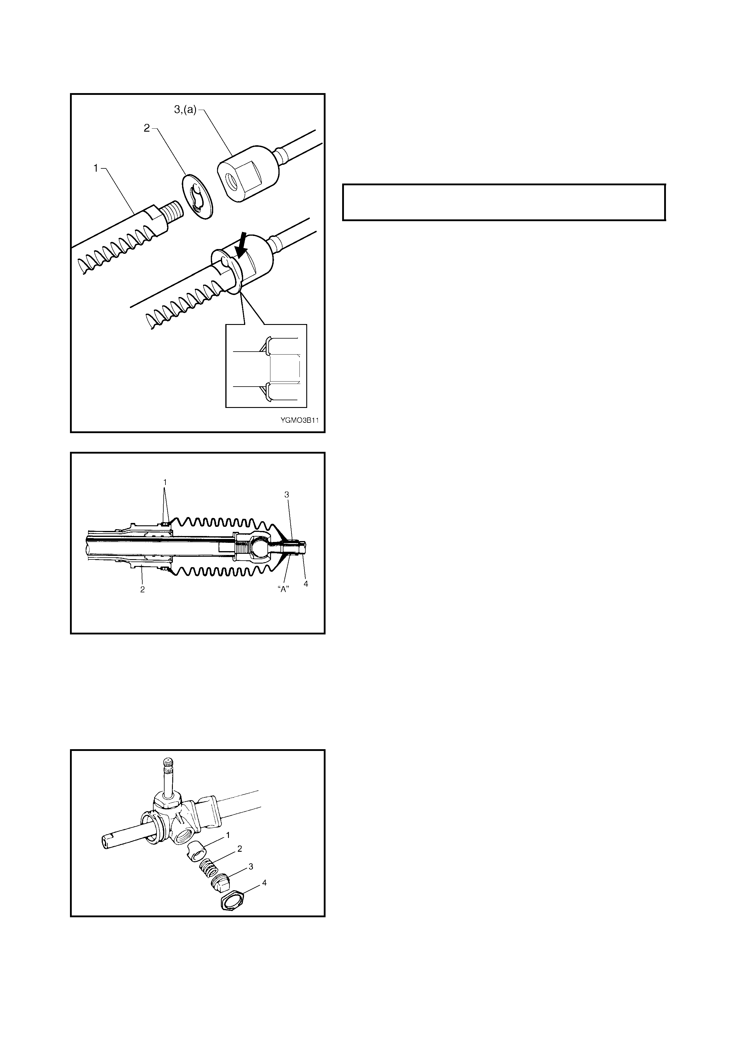
3.5 STEERING RACK PLUNGER
REMOVAL
1. Remove steering gear case, refer to 3.3, MANUAL
RACK AND PINION ASSEMBLY REMOVAL in this
Section.
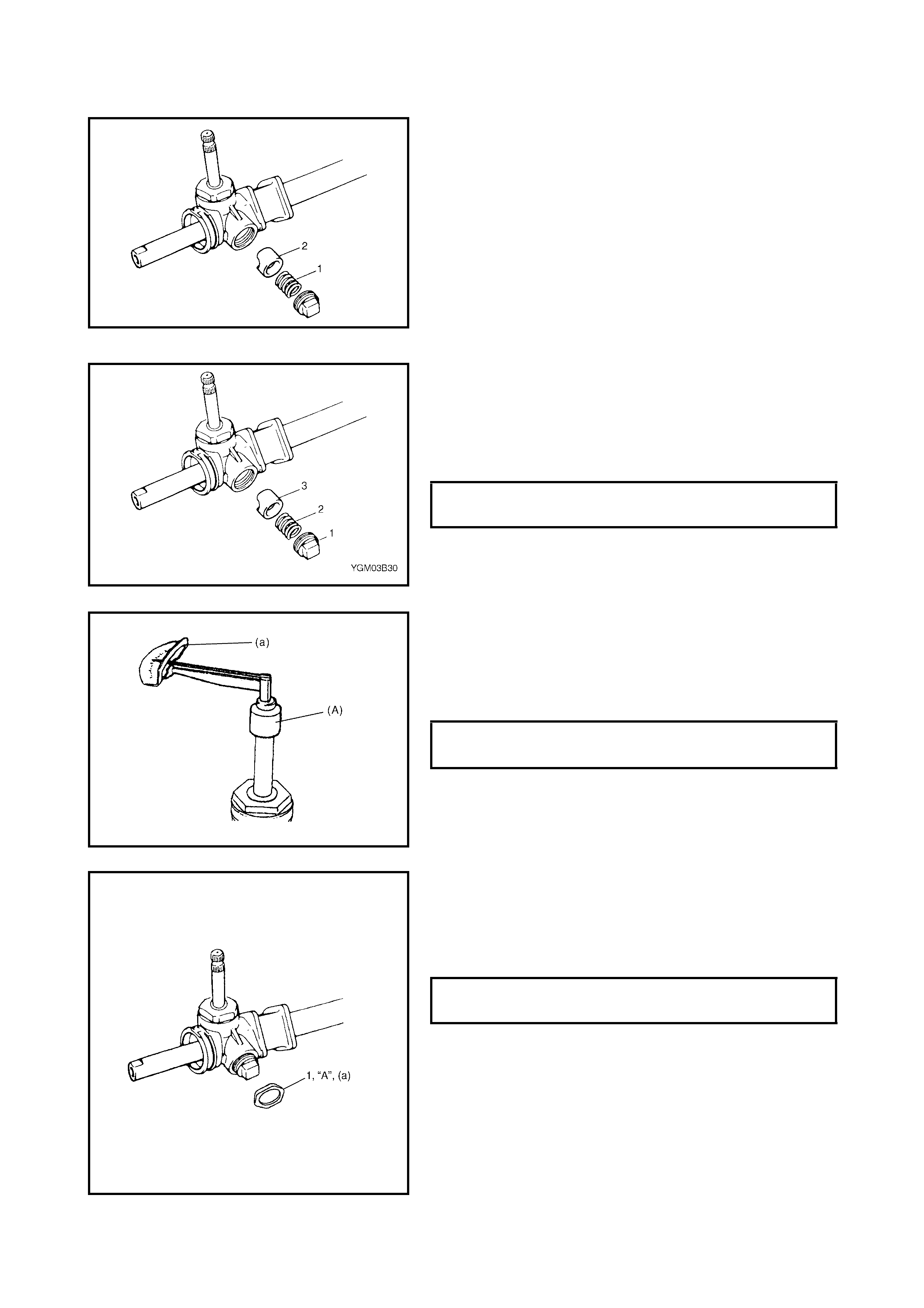
2. Remove rack damper screw lock nut (4), rack damper
screw (3), rack damper spr ing (2) and rack plunger (1).
TIE ROD INSIDE BALL NUT
TORQUE SPECIFICATION 85 Nm
INSPECTION
• Inspect rack plunger (2) for wear or damage.
• Inspect rack plunger spring (1) for deterioration.
In either case, if found defective, replace.
INSTALLATION
1. Apply lithium grease lightly to sliding part of plunger
against rack.
2. Install rack plunger (3), rack plunger spring (2), rack
damper screw (1) to steering case in direction shown.
Tighten rack damper screw to specified torque.
3. After tightening rack damper screw to specified torque,
special tool 09944-18211, turn it back by 30° ~ 50° and
check for rotation torque of pinion. If it is not as
specified below, adjust so that it will be within specified
torque range.
Also, check if rack as a whole moves smoothly.
4. Apply watertight sealant “A” to thread part of rack
damper screw lock nut (1) and tighten it to specified
torque (a) by not turning damper screw position
adjusted in step 3.
“A”: Watertight sealant - Three Bond No.1207C
5. After adjustment, put rack damper screw cap as deeply
as possible.
6. Install rack boots and tie rods refer to 3.4 RACK BOOT/
TIE ROD INSTALLATION in this Section.
7. Install steering gear case, refer to 3.3 MANUAL RACK
AND PINION ASSEMBLY INSTALLATION in this
Section.
RACK DAMPER SCREW
TORQUE SPECIFICATION 12 Nm
ROTATION TORQUER OF PINION (a)
TO RQUE SPECIFICATION 0.4 - 1.1 Nm
RACK DAMPER SCREW LOCK NUT (a)
TORQUE SPECIFICATION 40 Nm
3.6 STEERING PINION
REMOVAL
1. Remove rack plunger, refer to 3.5 STEERING RACK
PLUNGER in this Section.
2. Remove bearing plug with special tool 09944-26011
(A).
3. Tap on position as shown with plastic hammer (2) to
separate pinion assembly (1) from housing, and
remove pinion asse mbly.
4. Remove oil seal (2) from pinion bearing plug (1) with
specia l tool 09913-50121 (B).
INSPECTION
•Inspect pinion teeth surface (2) for wear or damage.
•Inspect oil seal (1) for dam age.
•Replace any par t found defective.
•Check rotation condition of bearing and inspect for
wear.
If foun d defective , r epla ce.
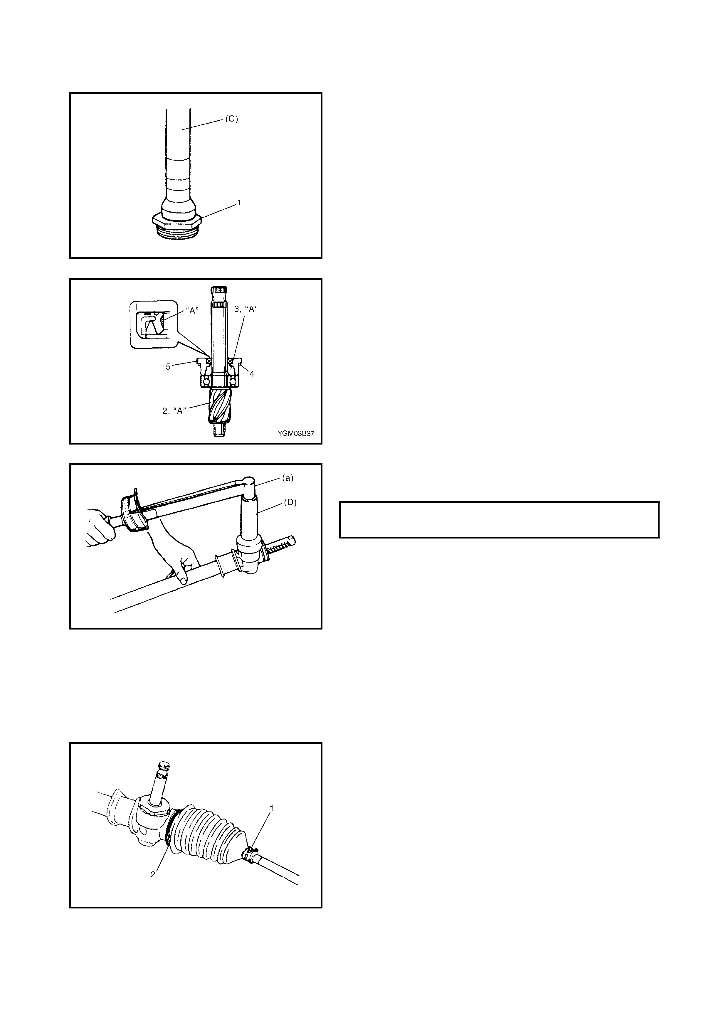
INSTALLATION
1. Install new oil seal to pinion bearing plug (1) using
special tool 09925-98210 (C).
2. Apply grease to all around pinion teeth (2), pinion
needle bearing, gear case O-ring (4) and gear case oil
seal lip (1).
Fill inside of pinion bearing plug (3) with lithium grease.
“A”: Lithium grease.
3. Install pinion assembly to gear case.
4. Tighten pinion bearing plug (a) to specified torque
using special tool 09944-26011 (B).
5. Install rack plunger, refer to 3.5 STEERING RACK
PLUNGER in this Section.
3.7 STEERING RACK
REMOVAL
1. Remove steering gear case, refer to 3.3 MANUAL
RACK AND PINION ASSEMBLY (STEERING GEAR
CASE) - REMOVAL in this Section.
2. Remove boot wires (2 ) and clips (1).
3. Move both boots toward tie rod end.
PINION BEARING PLUG
TORQUE SPECIFICATION 95 Nm
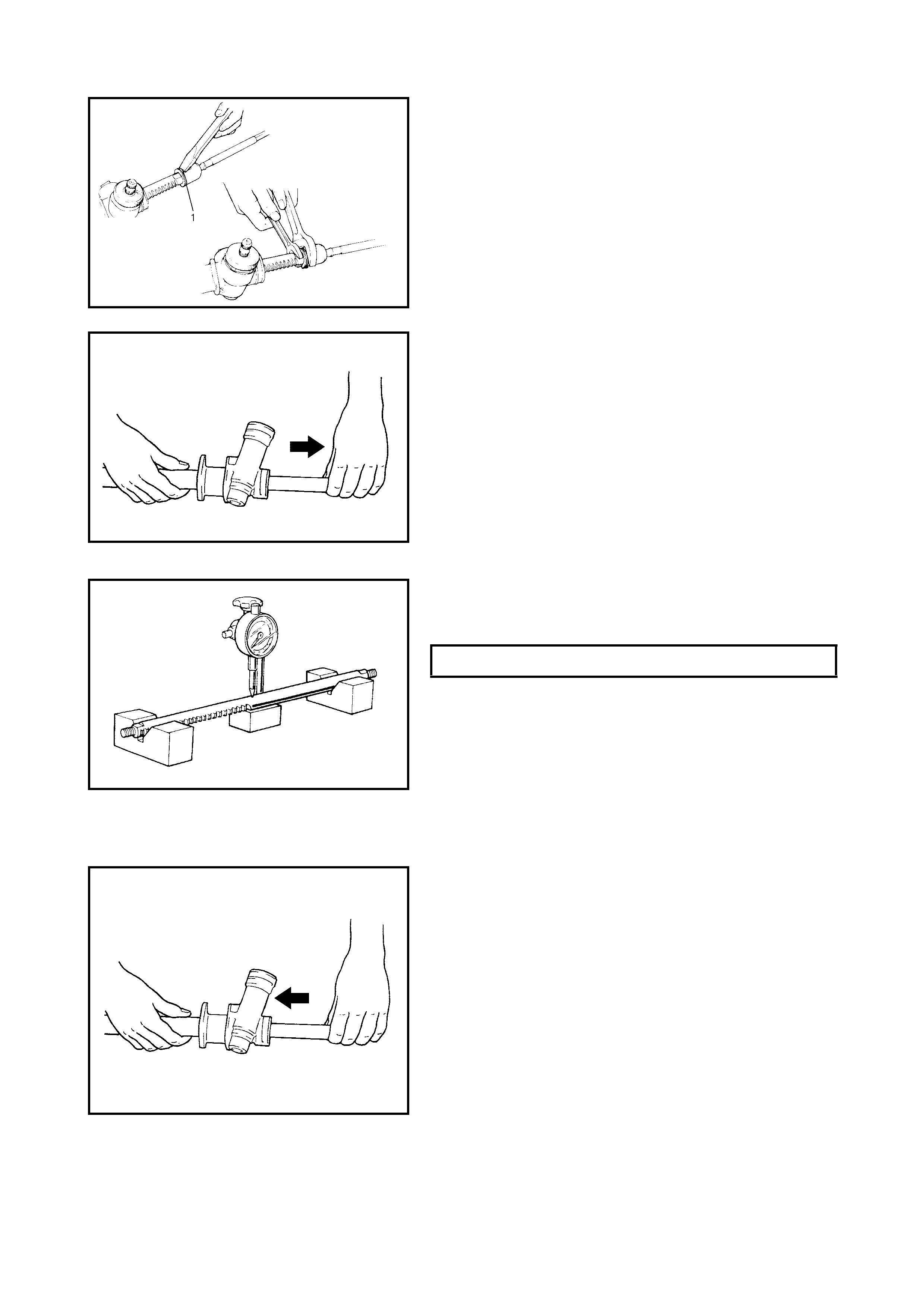
4. Straighten bent part of tie rod lock washers (1) and
remove tie rods from right and left sides of steering
rack.
5. Mark left and right tie rods accordingly.
6. Remove rack plunger and pinion assembly from gear
case, refer to Steps 1 – 3 in 3.6 STEERING PINION
REMOVAL in this Section.
7. Remove rack from gear case. Direction for rack
removal is as shown.
CAUTION: The inside of the steering rack bushing is
lined with a special coating which can be easily dam-
aged. Take care when removing rack from steering
gear case.
INSPECTION
Inspect for deflection, teeth wear, or damage, back surface
wear or damage.
If deflection exceeds limit, replace rack.
INSTALLATION
1. Apply grease to entire teeth surface of rack and its
periphery.
2. Slide rack into steering gear case in the direction as
shown.
CAUTION: The inside of the steering rack bushing is
lined with a special coating which can be easily dam-
aged. Take care when inserting rack into steering gear
case.
3. Install pinion assembly to gear case refer to Steps 2 –
4 in 3.6 STEERING PINION INSTALLATION in this
Section.
4. Perform Steps 1 – 5 in 3.5 STEERING RACK
PLUNGER INSTALLATION in this Section.
LIMIT OF RACK DEFLECTION 0.4 mm
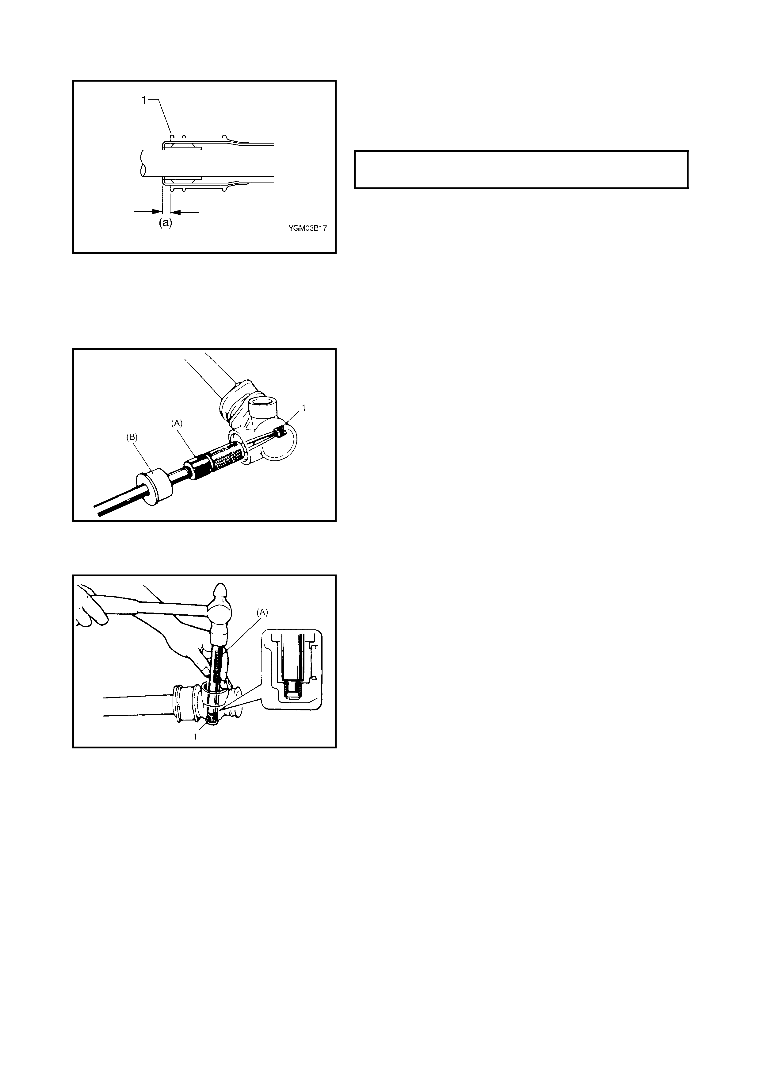
5. Before installing boot to rack side mount (1), make sure
that rack side mount (a) is positioned as shown. Install
tie rods to rack, refer to Steps 1 – 5 in 3.4 RACK
BOOT/TIE ROD INSTALLATION in this Section.
3.8 PINION BEARING
REMOVAL
1. Remove rack from steering gear case, refer to
3.7 STEERING RACK REMOVAL in this Section.
2. Remove pinion bearing (1) from gear cas e wi th special
tools (A) 09921-20200 (A) and (B) 09930-30102 as
shown.
INSTALLATION
1. Appl y grease to rollers of pinion bear ing.
2. Press-fit pinion b earing (1) into gear case with special
tool (A) 09943-88211 as shown.
After press-fitting, make sure that bearing rollers are
installed properl y.
3. Refer to Steps 1 – 5 in 3.7 STEERING RACK
INSTALLATION in this Section to complete installation.
RACK SIDE MOUNT INSTALLING
POSI T IO N (a ) 6.3 mm

4. REQUIRED SERVICE MATERIAL
5. SPECIAL TOOLS
NOTE: Refer to Section 0A GENERAL INFORMATION – 7. CONSOLIDATED TOOLS for a detailed list of
special tools and the local equivalent if one is available.
Material Recom m ended product Use
Lithium Grease
(Shou ld be applicable
for –40C° ~ 130°C)
Lithium Grease •Sliding part of rack against steering
hous ing (All around rack plunger, rack
bushing and rack)
•Sliding part against steering pinion
(Oil seal lip, needle bearing)
•Steeri ng rack and pinio n gear teeth
•Filled into pinion bearing cap
•Contacting parts of tie-rod and rack side
boots
•Rack end ball joint
Water tig ht Sealant Three Bo nd No. 1207C •Rack damper screw nut
•Pinion bearing plug thread
09913-65210 09913-50121 09921-20200 09925-98210
Tie-rod end remover Oil seal remover Pinion bearing rem over Bearin g installer
09930-30102 09944-18211 09944-26011
Sliding shaft Pinion torque checking
socket 43 mm Socket (Pinion
bear ing plug remover)