
SECTION 3B1 - ELECTRICAL POWER
STEERING (P/S) SYSTEM
1. GENERAL DESCRIPTION
1.1 SYSTEM COMPONENTS
2. WIRING DIAGRAM
3. DIAGNOSIS
3.1 ON-BOARD DIAGNOSTIC SYSTEM
3.2 PRECAUTIONS IN DIAGNOSING
TROUBLES
3.3 SYSTEM CHECK FLOW TABLE
Customer Questionnaire Example
3.4 EPS WARNING LAMP CHECK
3.5 DTC CHECK
Using Tech 2
Not Using Tech 2
3.6 DTC CLEARANCE
Using Tech 2
Not Using Tech 2
3.7 SERIAL DATA LINK CIRCUIT CHECK
Diagnostic Flow Table
3.8 DTC TABLE
3.9 TABLE A - EPS WARNING LAMP DOES
NOT ILLUMINATE WITH IGNITION
SWITCH ON AND WITH ENGINE NOT
RUNNING
Circuit
Inspection
3.10 TABLE B - EPS WARNING LAMP
FLASHES WITH IGNITION SWITCH ON
Circuit
3.11 TABLE C - EPS WARNING LAMP DOES
NOT FLASH, REMAINS ON OR OFF,
EVEN WITH DIAGNOSIS SWITCH
TERMINAL GROUNDED
Circuit
3.12 DTC C1111 (DTC No.11) TORQUE
SENSOR MAIN CIRCUIT FAILURE
3.13 DTC C1113 (DTC No.13) TORQUE
SENSOR MAIN AND SUB CIRCUIT
FAILURE
3.14 DTC C1115 (DTC No.15) TORQUE
SENSOR SUB CIRCUIT FAILURE
3.15 DTC C1114 (DTC No.14) TORQUE
SENSOR 5V POWER SUPPLY CIRCUIT
FAILURE
3.16 DTC C1116 (DTC No.16) TORQUE
SENSOR 8V POWER SUPPLY CIRCUIT
FAILURE
3.17 DTC C1121/C1123/C1124
(DTC No.21/23/24) VSS CIRCUIT
FAILURE
3.18 DTC C1122 (DTC No.22) ENGINE SPEED
SIGNAL CIRCUIT FAILURE
3.19 DTC C1141/C1142/C1143/C1144/C1145
(DTC No.41/42/43/44/45) MOTOR
CIRCUIT FAILURE
3.20 DTC C1151 (DTC No.51) CLUTCH
CIRCUIT FAILURE
3.21 DTC C1153(DTC No.53) P/S CONTROL
MODULE POWER SUPPLY CIRCUIT
FAILURE
WARNING:
For vehicles equipped with Supplemental Restraint (Airbag) System:
• Service on and around the airbag system components or wiring must be performed only by an
authorised HOLDEN retailer. Refer to AIRBAG SYSTEM COMPONENTS AND WIRING LOCATION
VIEW under GENERAL DESCRIPTION in Section 10B AIRBAG SYSTEM in order to confirm
whether you are performing service on or near the airbag system components or wiring. Please
observe all WARNINGS and SERVICE PRECAUTIONS under ON-VEHICLE SERVICE in Section
10B AIRBAG SYSTEM before performing service on or around the airbag system components or
wiring. Failure to follow WARNINGS could result in unintentional activation of th e system or could
render the system inoperative. Either of these two conditions may result in severe injury.
• Technical service work must be started at least 90 seconds after the ignition switch is turned to
the “LOCK” position and the negative cable is disconnected from the battery. Otherwise, the sys-
tem may be activated by reserve energy in the Sensing and Diagnostic Module (SDM).
IMPORTANT:
Prior to connecting Tech 2 to the vehicle, ref e r to Section 0C TECH 2.

3.22 DTC C1152/C1154/C1155 (DTC No.52/54/
55) P/S CONTROL MODULE FAILURE
3.23 TROUBLE DIAGNOSIS (FOR TROUBLE
NOT INDICATED BY ON-BOARD
DIAGNOSTIC SYSTEM)
3.24 INSPECTION OF THE P/S CONTRO L
MODULE AND ITS CIRCUITS
Voltage Check
3.25 STEERING WHEEL PLAY INSPECTION
3.26 STEERING FORCE INSPECTION
4. ON-VEHICLE SERVICE
4.1 STEERING COLUMN ASSEMBLY
Removal
4.2 CHECKING STEERING COLUMN
ASSEMBLY AND LOWER SHAFT FOR
ACCIDENT DAMAGE
Checking Procedure
4.3 P/S CONTROL MODULE
Removal
Installation
4.4 TORQUE SENSOR
On-Vehicle Inspection
4.5 MOTOR ASSEMBLY (WITH CLUTCH
INCORPORATED)
On-Vehicle Inspection
5. SPECIAL TOOLS
1. GENERAL DESCRIPTION
1.1 SYSTEM COMPONENTS
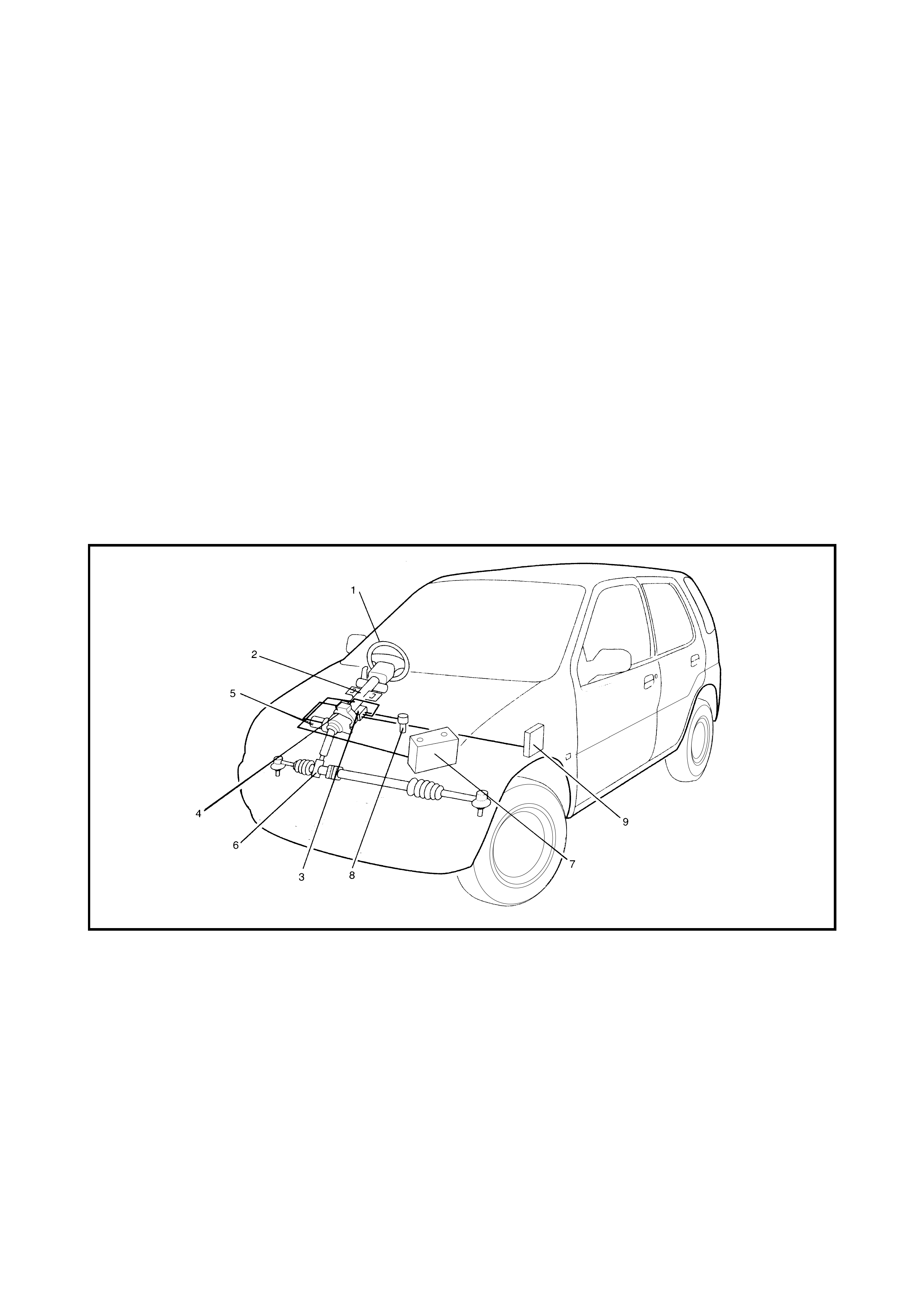
The electrical power steering (P/S) system consists of a P/S control module, a torque sensor and a motor and
clutch installed to the steering column.
The P/S control module determines the level and direction of the assist force for the steering wheel according
to the sig nals from the torqu e sensor and the vehic le speed and then oper ates the moto r to assis t the opera-
tion of the steering wheel.
When the ignition switch is ON and the engine is running, the P/S control module diagnoses faults which may
occur in the following components:
• Torque sensor
• Vehicle speed sensor (VSS) circuit
• Engine speed signal circuit
• Motor
•Clutch
• P/S control module
When P/S control module detects a malfunction, it stops the motor and clutch control.
Legend
1. Steering wheel 4. Torque sensor 7. Battery
2. Steering column assembly 5. Motor and clutch 8. VSS
3. P/S control module 6. Steering gear box 9. ECM
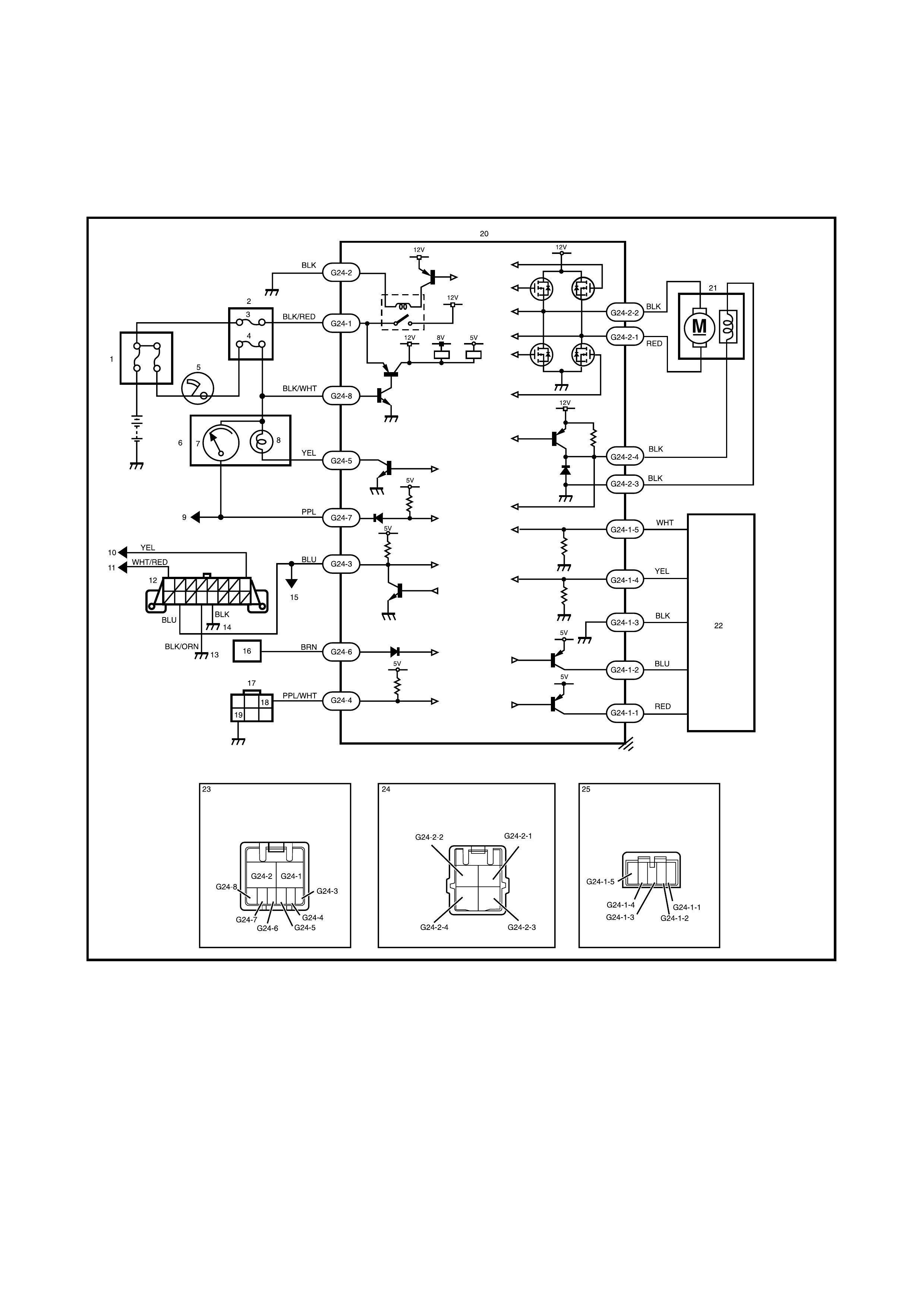
2. WIRING DIAGRAM
Legend
YGM3B131
1. Main fuse box 10. To immobiliser control module 19. Ground terminal
2. Circuit fuse box 11. To circuit fuse box 20. P/S control module
3. P/S fuse (30A) 12. Data link connector (DLC) 21. Motor assembly
(with clutch incorporated)
4. IG fuse (15A) 13. Ground on body
5. Ignition switch 14. Ground on engine block 22. Torque sensor
6. Combination meter 15. To ECM, air bag SDM and 22. Torque sensor
7. Speed meter ABS hydraulic unit/control 23. Connector G24
8. EPS warning lamp module assembly (viewed from harness side)
9. To vehicle speed sensor 16. To ECM 24. Connector G24-2
(VSS) 17. Diagnosis connector No. 2 (viewed from harness side)
18. Diagnosis switch terminal 25. Connector G24-1
(for P/S system) (viewed from harness side)
3. DIAGNOSIS
The P/S system is controlled by the P/S co ntrol module which has an on-board diagnostic system to detect
malfunctions in the system.
When diagnosing faults, be sure to have a full understanding of the outline of 3.1 ON-BOARD
DIAGNOSTIC SYSTEM and each item in 3.2 PRECAUTION IN DIAGNOSING TROUBLES and execute
diagnos is, refer to 3.3 SYSTEM CHECK FLOW TABLE in this Section.
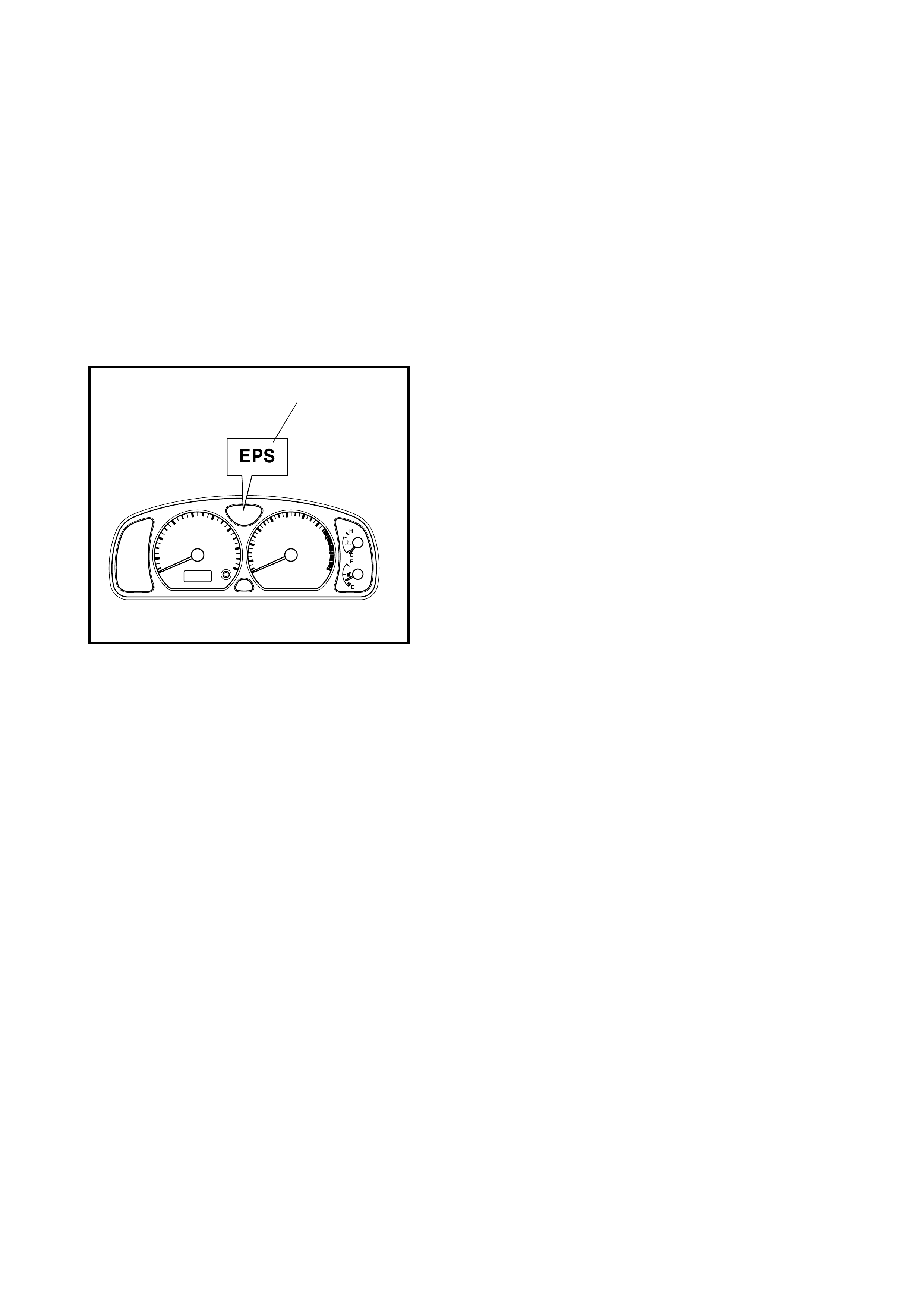
3.1 ON-BOARD DIAGNOSTIC SYSTEM
The P /S con t rol mo dul e pe rfo rms o n- boa rd d ia gnos is ( self-
diagnos is) on the s ystem and op erates EPS warning lamp
(1) (malfunction indicator lamp) as follows:
• Malfunction indicator lamp (EPS warning lamp) lights
when the ignition switch is turned to ON position (but
with the engine not running) regardless of the condition
of the P/S control system. This is only to check the
malfunction indicator lamp (EPS warning lamp) bulb
and its circuit.
• If the areas monitored by the P/S control module are
free from any faults after the engine starts (while
engine is running), the malfunction indicator lamp (EPS
warning lamp) turns OFF.
• When the P/S con tr ol mod ule detec ts a fault which has
occurred in the areas it monitors, the malfu nction indi-
cator lamp (EPS warning lamp) turns ON while the
engine is running to warn the driver of such occurrence
of trouble and at the same time it stores the exact trou-
ble area in memory inside the P/S control module.
3.2 PRECAUTIONS IN DIAGNOSING TROUBLES
• Take a note of DTC indicated first.
• Before inspection, refer to Section 0A PRECAUTIONS FOR ELECTRICAL CIRCUIT SERVICE.
• When tw o or mor e trou ble s ha ve occ urr ed, their DTCs ar e in dicated 3 times eac h, s tarting with the s mal l-
est code number.
• DTC C1122 (DTC No.22) (engine speed signal failure) is indicated when the ignition switch is in the ON
position and the engine is not running but if the indication changes to normal when the engine is started, it
means there is nothing abnormal.
• As DTCs are stored in the memory of the P/S control module, be sure to clear the memory after any
repairs by performing the DTC clearance procedure, refer to 3.6 DTC CLEARANCE in this Section.
1

3.3 SYSTEM CHECK FLOW TABLE
WARNING: Carry out test in a low traffic area to prevent an accident.
Step Action Yes No
1. 1. Record details of the problem (failure, complaint) and how it
occurred as described by the customer.
For this purpo se, use of a questionai re form as shown bel ow
will facilitate collecting information to the point required for
proper analysis and diagnosis.
2. Check if what the customer claimed in the CUSTOMER
QUESTIONAIRE is actually found in the vehicle and if that
symptom is found, whether it is identified as a failure.
(This step should be shared with the customer if possible.)
3. Check malfunction indicator lamp (EPS warning lamp)
operation referring to MALFUNCTION INDICATOR LAMP
(EPS WARNING LAMP) CHECK.
4. Check DTC referring to DTC CHECK in this Section and
record the DTC(s).
5. Clear DTC if any malfunction DTC exists referring to DTC
CLEARANCE in this section, then recheck DTC.
6. Is any malfunction DTC detected?
Go to Step 2. Go to Step 3.
2. 1. Inspect and repair referring to applicable 3.8 DTC TABLE in
this Section.
2. Clear the DTC referring to 3.6 DTC CLEARANCE in this
Section.
3. Does the trouble recur?
Go to Step 5. Go to Step 4.
3. 1. Test drive the vehicle and turn steering wheel fully to the right
and left during test driving; refer WARNING. Check if any
trouble exists.
2. Inspect and repair basic parts refer to Section 3,
1.1 GENERAL DIAGNOSIS.
3. If the trouble cannot be repaired in Step 3-2, inspect and
repair, refer to 3.23 TROUBLE DIAGNOSIS (FOR TROUBLE
NOT INDICATED BY ON-BOARD DIAGNOSTIC SYSTEM)
in this Section.
4. Does the trouble recur?
Go to Step 5. Go to Step 4.
4. 5. Confirm that the problem symptom no longer exists and the
P/S system is free from any abnormal conditions. If the
repaired item is related to the malfunction DTC, clear the
DTC once and perform a test drive as in S tep 3-1 and confirm
that no DTC is indicated.
6. Is any malfunction DTC detected?
Go to Step 5. END
5. 1. Check DTC refer to 3.5 DTC CHECK in this Section.
2. Is any malfunction DTC detected? Go to Step 2. Go to Step 3.

NOTE:
• As exec ution of the DTC CLEA RANC E will cl ear all malf unction DTCs, be sure to re cord all DTCs befor e
servicing.
• When 2 or more codes are indicated, the lowest numbered code will appear first.
• If a code not listed on the DTC TABLE is displayed, then the P/S control module is faulty.
• DTC C1122 or DTC No.22 (flashing pattern: 22) is indicated when the ignition switch is ON and the engine
is not running but if DTC No.12 (flashing pattern: 12) is indicated when the engine is started, it means
nothing abno r mal.
• Current DTC and history DTC can be identified by lighting and flashing of the EPS warning lamp.
The EPS warning lamp operates as follows depending on the fault condition.
To identify current DTC, clear history DTC, refer to 3.6 DTC CLEARANCE in this Section.
Current DTC is set.
(Abnormality exists
at present.)
History DTC is set only.
(Faulty condition
occurred once in the
past but normal condi-
tion is restored at
present.)
Current DTC and his-
tory DTC exist.
EPS warning lamp after
engine started Remains ON. Turn OFF. Remains ON.
EPS warning lamp when
shorting diagnosis switch
terminal and ground
terminal
Displays current DTC. Displays history DTC. Displays current DTC and
history DTC.
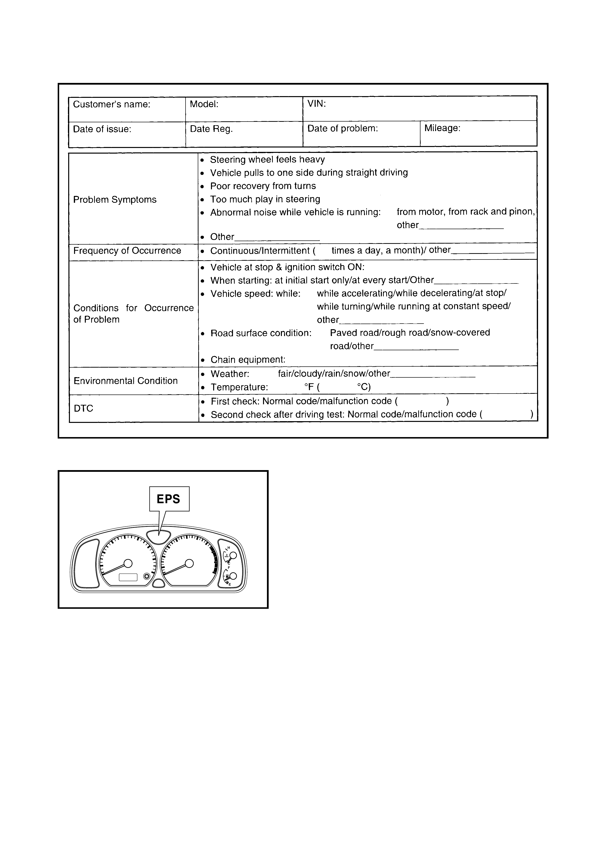
CUSTOMER QUESTIONNAIRE (EXAMPLE)
3.4 EPS WARNING LAMP CHECK
1. Tu rn ign ition s witc h to ON pos i tio n (but without runnin g
engine), check that EPS warning lamp lights up. If
lamp does not light up, refer to 3.9 TABLE A - EPS
WARNING LAMP DOES NOT ILLUMINAATE WITH
IGNITION SWITCH ON POSITION BUT WITH
ENGINE NOT RUNNING in this Section. If lamp
flashes , refer to 3.10 TABLE B - EPS WARNING LAMP
FLASHES AT IGNITION SWITCH ON in this Section.
2. Start engine and check that the malfunction indictor
lamp (EPS warning light) turns OFF.
If lamp goes OFF, P/S system is in good condition.
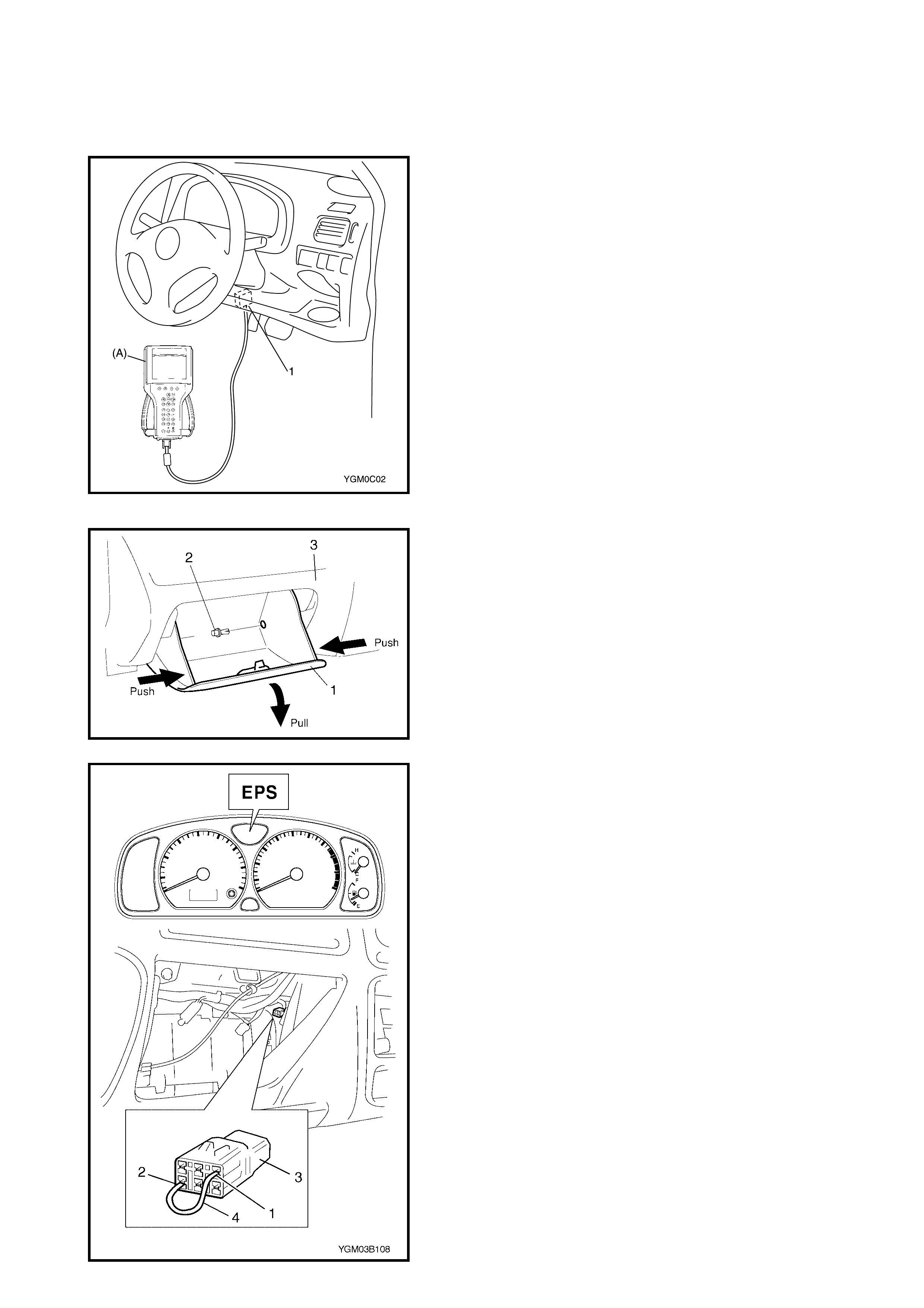
3.5 DTC CHECK
USING TECH 2
1. Turn ignition switch to OFF position.
2. Connect Tech 2 (A) to data link connector (DLC) (1)
located b eside the d rivers side of the ins trument panel
centre facia.
3. Turn ignition switch to ON position.
4. Read DTC according to instructions displayed on
Tech 2 and print it or write it down and refer to
Section 0C TECH 2 for further details.
NOTE: If Tech 2 cannot display DTC, refer to
3.7 SERIAL DATA LINK CIRCUIT CHECK in this Section.
5. After completing the check, turn ignit ion switch to OFF
position and disconnect Tech 2 from DLC.
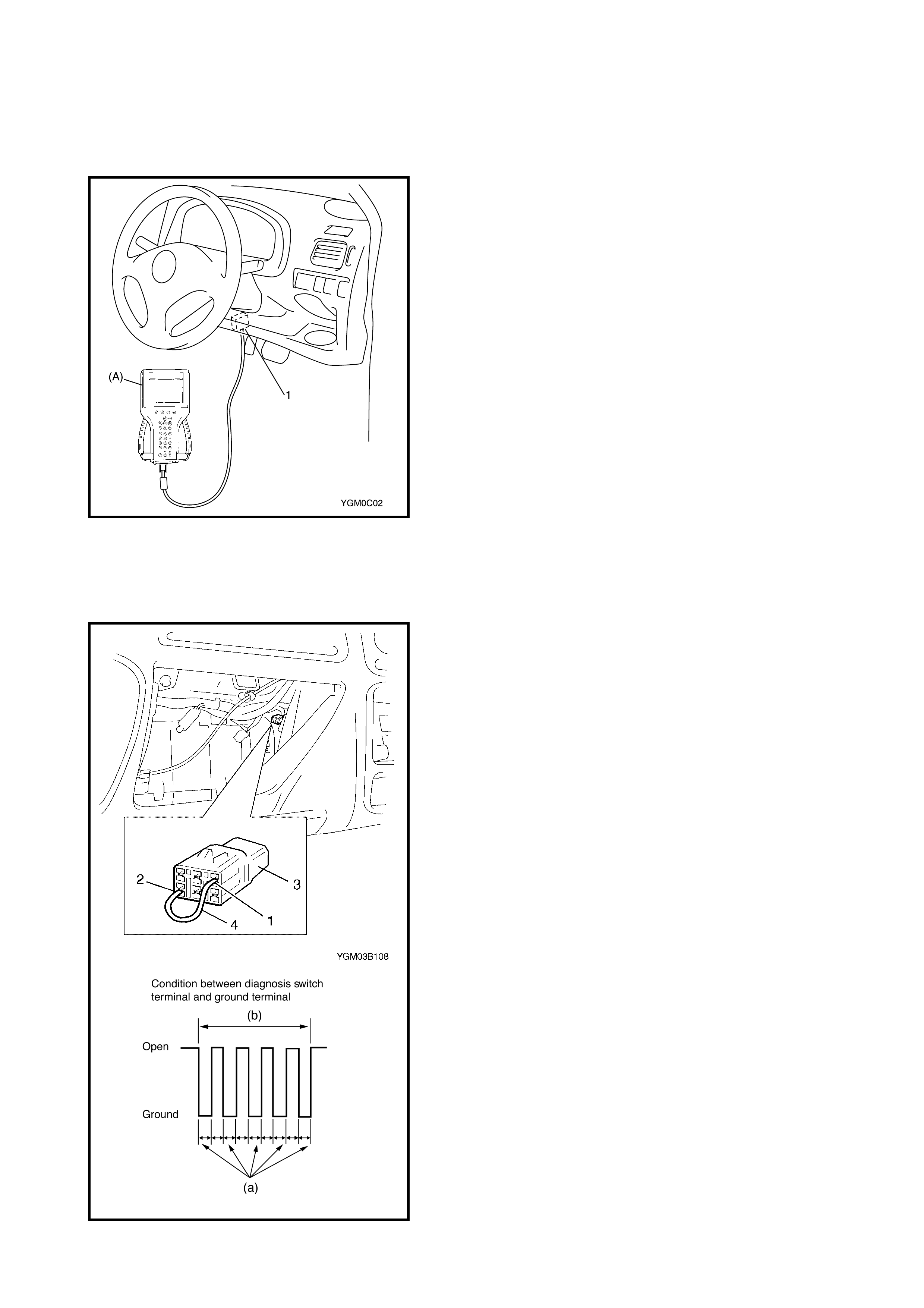
NOT USING TECH 2
1. Remove the glove box.
Open the glove box (1), then while pressing the glove
box stoppe r, pull out the glove b ox from the instrume nt
panel (3) and remove the glove box clip (2) and glove
box from the instrument panel.
2. Apply chocks to wheels, set shift lever to neutral
position and fully apply parking brake.
3. Start engine.
4. Using jumper wire (4), short diagnosis switch terminal
(1) to ground term inal (2) of dia gnosis conne ctor No. 2
(3).
5. Read flashing of EPS warning lamp which represents
DTC and write it down. When more than 2 DTCs are
stored in memory, each DTC is repeated 3 times
starting with the smallest DTC number in increasing
order.
For details and example of DTC, refer to
3.8 DTC TAB LE in this Section.
NOTE: DTC No.22 is indicated when the ignition switch is
ON and the e ngine i s not runni ng, but if DT C No.12 is in di-
cated when the engine is started, it means nothing abnor-
mal.
6. After completing the check, turn the ignition switch to
OFF position and disconnect jumper wire (4) from
diagnosis connector No. 2.
3.6 DTC CLEARANCE
USING TECH 2
1. Turn ignition switch to OFF position.
2. After setting the cartridge connect Tech 2 (A) to data
link connector (DLC) (1) located beside the drivers side
of the instrument panel centre facia.
3. Turn ignition switch to ON position.
4. Erase DTC according to instructions displayed on
Tech 2 refer to Section 0C TECH 2 for further details.
5. After co mpleting the check, turn ignition switc h to OFF
position and disconnect Tech 2 from DLC.
NOT USING TECH 2
1. Remove glove box, refer to 3.5 DTC CHECK in this
Section.
2. Turn ignition switch to ON position.
3. Using jumper wire, short diagnosis switch terminal (1)
to ground terminal (2) of diagnosis connector No.2 (3).
4. Conn ect and disconne ct one end of th e jumper wi re at
least 5 times within 10 seconds.
DTC clearance procedure specifi cation
(a): about 1 second
(b): within 10 seconds
5. Perform DTC CHECK and confirm that normal DTC
(DTC No.12) is displayed and not malfunction DTC.
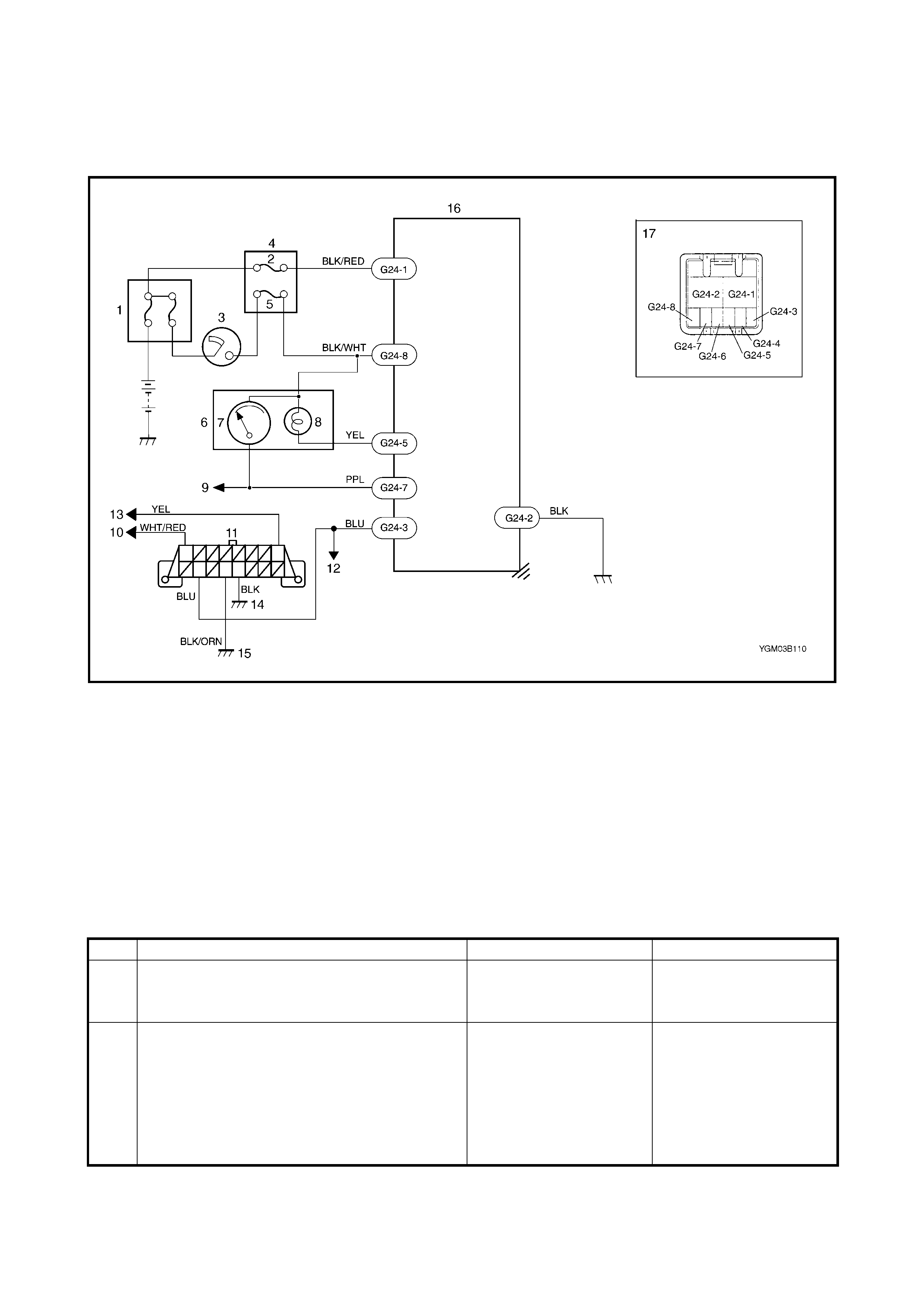
3.7 SERIAL DATA LINK CIRCUIT CHECK
CAUTION: Be sure to perform 3.3 SYSTEM CHECK FLOW TABLE before starting diagnosis according
to flow table.
Legend
DIAGNOSTIC FLOW TABLE
1. Main fuse box 8. EPS warning lamp 13. To immobiliser control module
2. P/S fuse (30 A) 9. To vehicle speed sensor 14. Ground on body
3. Ignition switch (VSS) 15. Ground on engine block
4. Circuit fuse box 10. To circuit fuse box 16. P/S control module
5. IG meter fuse (15 A) 11. Data link connector (DLC) 17. Connector G24
6. Combination meter 12. To ECM, SDM and ABS (viewed from harness side)
7. Speedometer hydraulic unit/control module
assembl y if (equi pped )
Step Action Yes No
1. Was “SYSTEM CHECK FLOW TABLE” per-
formed? Go to Step 2. Go to 3.3 SYSTEM
CHECK FLOW TABLE in
this Section.
2. 1. Make sure that Tech 2 is functioning
correct ly and th e corr ect cartri dge for t he
P/S system is used.
2. Turn ignition switch to OFF position.
3. Check proper connection of Tech 2 to
DLC.
4. Is connection in good condition?
Go to Step 3. Connect Tech 2 to DLC
correctly.
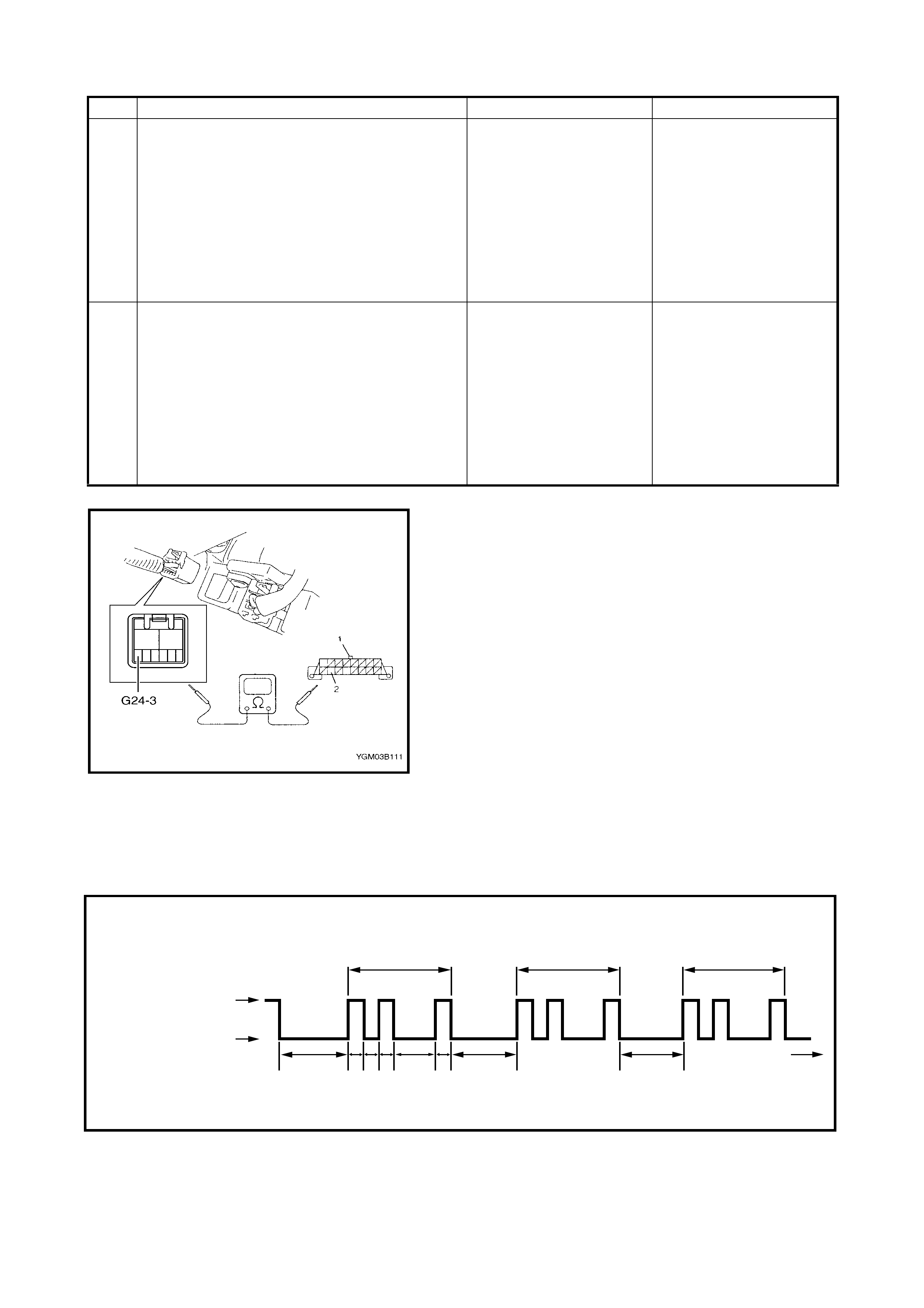
Figure 1 for Step 4
3.8 DTC TABLE
CAUTION: Perform 3.3 SYSTEM CHECK FLOW TABLE in this Section before starting diagnosis
according to flow table of each DTC.
3. 1. Check if communication is possible by
trying communication with other
controller (ECM, ABS hydraulic unit/
contro l module ass embly (if eq uipped) o r
SDM).
Is it possible to communicate with other con-
troller?
Go to Step 4. Repair open in common
section of serial data cir-
cuit (BLU wire circuit)
used by all controllers or
short to ground or power
circuit which has
occurred somewhere in
serial data circuit (BLU
wire circuit).
4. 1. With ignition switch in OFF position,
disconnect 8-pin (G24) connector from P/
S control module.
2. Check proper connection at G24-3 (BLU
wire) (2) terminal fo r serial data circuit.
3. If OK, then check resistance between
G24-3 (BLU wire) terminal and BLU wire
terminal for serial data circuit in DLC (1).
4. Is resistance 1 Ω or less?
Substitute a known-good
P/S control module and
recheck.
Repair high resistance or
open in BLU wire circuit
for P/S system.
Step Action Yes No
21
3.0 0.30.3 0.30.3 1.0 3.0 3.0
21 21
Example : When VSS circuit fail (DTC 1121, DTC No.21) is set
“EPS” light
Turn ON
Turn OFF
TIME
(sec.)
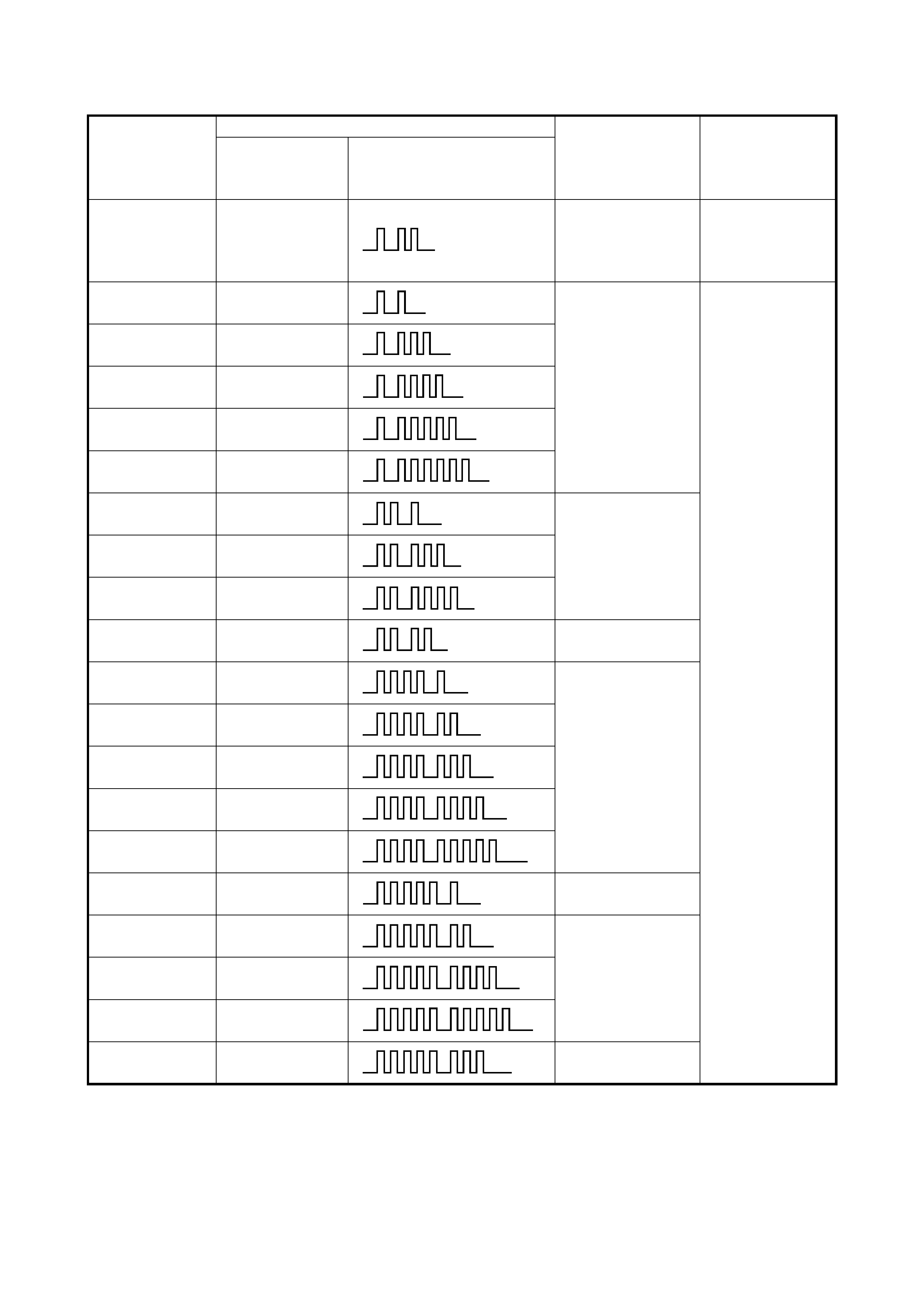
DTC (displayed
on Tech 2)
“EPS” light flashing pattern
DTC (indicated
by EPS light
flashing pattern) Model DI AGNOSTIC
ITEM DIAGNOSIS
NO DTC 12 Normal
This code appears
when none of the
other codes are
identified.
C1111 11
Torque sensor
Diagnose trouble
according to the
DIAGNOSTIC
FLOW TABLE
corresponding to
each code No.
C1113 13
C1114 14
C1115 15
C1116 16
C1121 21
VSS signa lC1123 23
C1124 24
C1122 22 Engine speed
signal
C1141 41
Motor
C1142 42
C1143 43
C1144 44
C1145 45
C1151 51 Clutch
C1152 52
P/S control moduleC1154 54
C1155 55
C1153 53 P/S control module
power supply
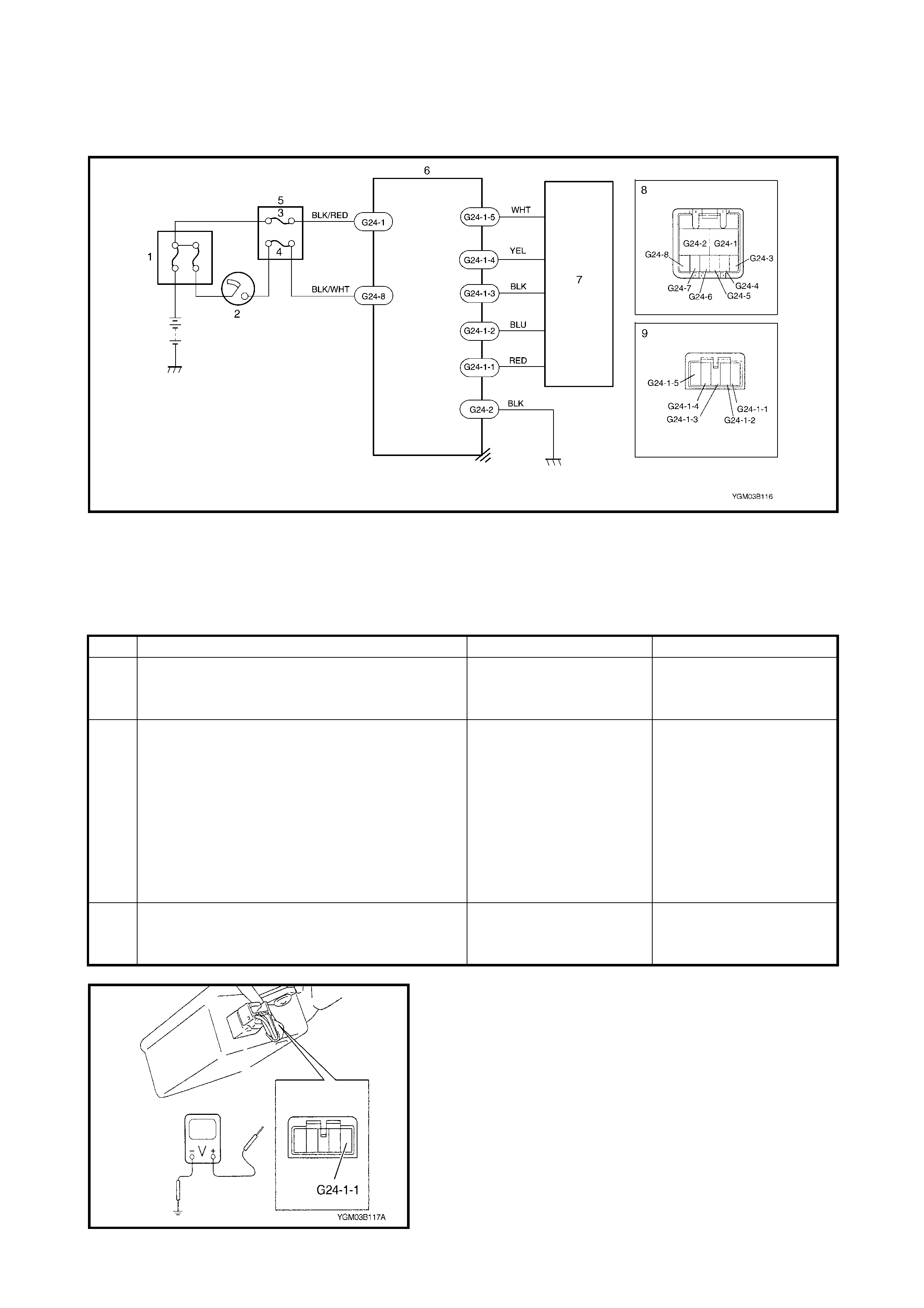
3.9 TABLE A - E PS WARNING LAMP DOES NOT ILLUMINATE WITH IGNITION
SWITCH ON AND WITH ENGINE NOT RUNNING
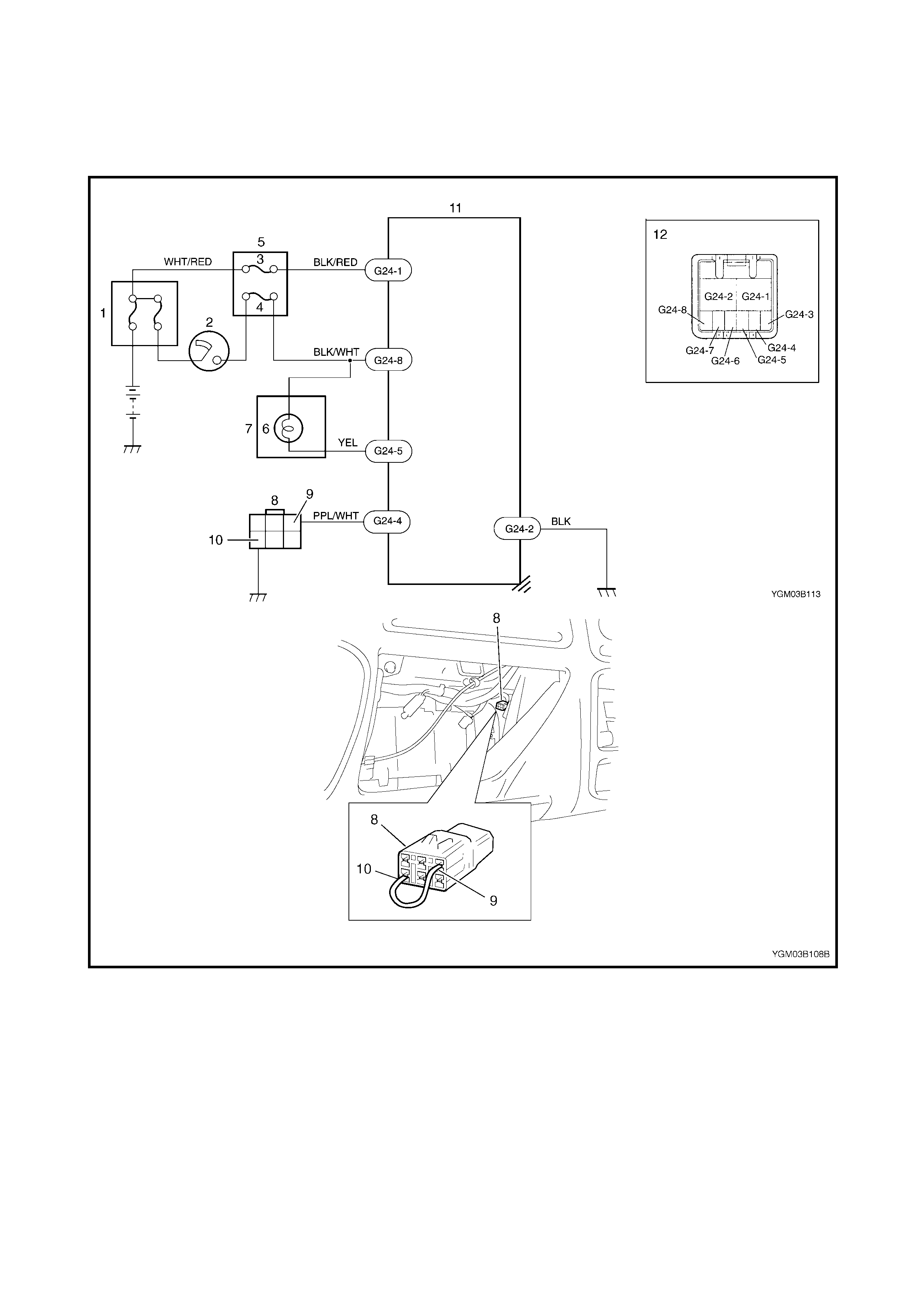
CIRCUIT
Legend
1. Main fuse box 5. Circuit Fuse box 9. Diagnosis switch terminal
2. Ignition switch 6. EPS warning lamp 10. Ground terminal
3. P/S fuse (30A) 7. Combination meter 11. P/S control module
4. IG fuse (15A) 8. Diagnosis connector No.2 12. Connector G24 (viewed from
harness side)

INSPECTION
Step Action Yes No
1. 1. S et parking brak e.
2. Note combination meter when ignition
switch is turned to ON position.
Does the BRAKE indicator (warning lamp)
come ON?
Go to Step 2. BLK/YEL, BLK/WHT wire
circuit or
IG fuse open or short to
ground.
2. 1. Ignition switch OFF.
2. Remove and inspect P/” fuse.
3. Is fuse in good condition?
Reinstall P/S fuse, and
then go to Step 3. Check BLK/RED wire cir-
cuit for short to ground.
If OK, replace P/S fuse.
3. 1. Turn ignition switch OFF.
2. Remove and inspect EPS warning lamp
bulb and combination meter referring to
Section 8, 2.10 COMBINATION METER.
Are they in good conditi on?
Reinstall EPS warning
lamp bulb and combina-
tion meter , and then go to
step 4.
Replace EPS warning
lamp bulb or combination
meter.
4. 1. With ignition switch OFF, disconnect P/S
control module con nector (G24).
2. Check proper connection to P/S control
module at G24-1 terminal.
3. If OK, check voltage between G24-1
(BLK/RED wire) terminal and body
ground with ignition switch ON.
Is it 10 – 14 V?
Go to Step 5. WHT/RED or BLK/RED
wire circuit open or short
to ground.
5. 1. Check proper connection to P/S control
module at G24-8 terminal.
2. If OK, check voltage between G24-8
(BLK/WHT wire) terminal and body
ground with ignition switch ON.
Is it 10 – 14 V?
Go to Step 6 BLK/WHT wire circuit
open or short to ground.
6. 1. Check proper connection to P/S control
module at G24-5 terminal.
2. If OK, check voltage between G24-5
(YEL wire) terminal and body ground with
ignition switch ON.
Is it 10 – 14 V?
Substitute a known -g ood
P/S control module and
re-check.
Check YEL wire circuit
open or short to ground.

3.10 TABLE B - EPS WARNING LAMP FLASHES
WITH IGNITION SWITCH ON
CIRCUIT
Refer to 3.9 TABLE-A in this Section for System Circuit Diagram.
3.11 TABLE C - EP S WARNING LAMP DOES NOT FLASH, REMAINS ON OR OFF,
EVEN WITH DIAGNOSIS SW ITC H TERMINAL GROUNDED
CIRCUIT
Refer to 3.9 TABLE-A in this Section for System Circuit Diagram.
Step Action Yes No
1. 1. Check diagnosis connector No.2
Is it connected to diagnosis switch terminal (8)
and ground terminal (9) in diagnosis connector
No.2 by jumper wire?
Disconnect jumper wire
from diagnosis connec-
tor No. 2.
Go to Step 2.
2. 1. Check voltage between diagnosis switch
terminal of diagnosis connector No.2 and
body ground with ignition switch ON.
Is it 4 – 6 V?
Substitute a known-good
P/S control module and
recheck.
PPL/WHT wire circuit
short to ground.
Step Action Yes No
1. 1. Inspect jumper wire connection between
diagnosis switch and ground terminals on
diagnosis connector No.2.
Is it securely co nnec te d.
Go to Step 2. Properly connect jumper
wire diagnosis switch and
ground terminals on diag-
nosis connector No.2.
2. 1. With ignition switch OFF, disconnect P/S
control module connector (G24).
2. Check proper connection to P/S control
module at G24-4 terminal.
3. If OK, check resistance between G24-4
(PPL/WHT wire) terminal and diagnosis
switch terminal of diagnosis connector
No.2.
Is there contin ui ty?
Go to Step 3. PPL/WHT wire circuit
open.
3. 1. Check proper connection to P/S control
module at G24-2 terminal.
2. If OK, check resistance between G24-2
(BLK wire) terminal and body ground.
Is there contin ui ty?
Go to Step 4. BLK wire circuit open.
4. 1. Check proper connection to P/S control
module at G24-5 terminal.
2. If OK, check voltage between G24-5
(YEL wire) terminal and body ground with
ignition switch ON.
Is it 10 – 14 V?
Substitute a known-good
P/S control module and
recheck.
YEL wire circuit or inside
of combination meter
short to other circuit or
ground.
3.12 DTC C1111 (DTC NO.11) TORQUE SENSOR MAIN CIRCUIT FAILURE
3.13 DTC C1113 (DTC NO.13) TORQUE SENSOR MAIN AND SUB CIRCUIT FAILURE
3.14 DTC C1115 (DTC NO.15) TORQUE SENSOR SUB CIRCUIT FAILUR E
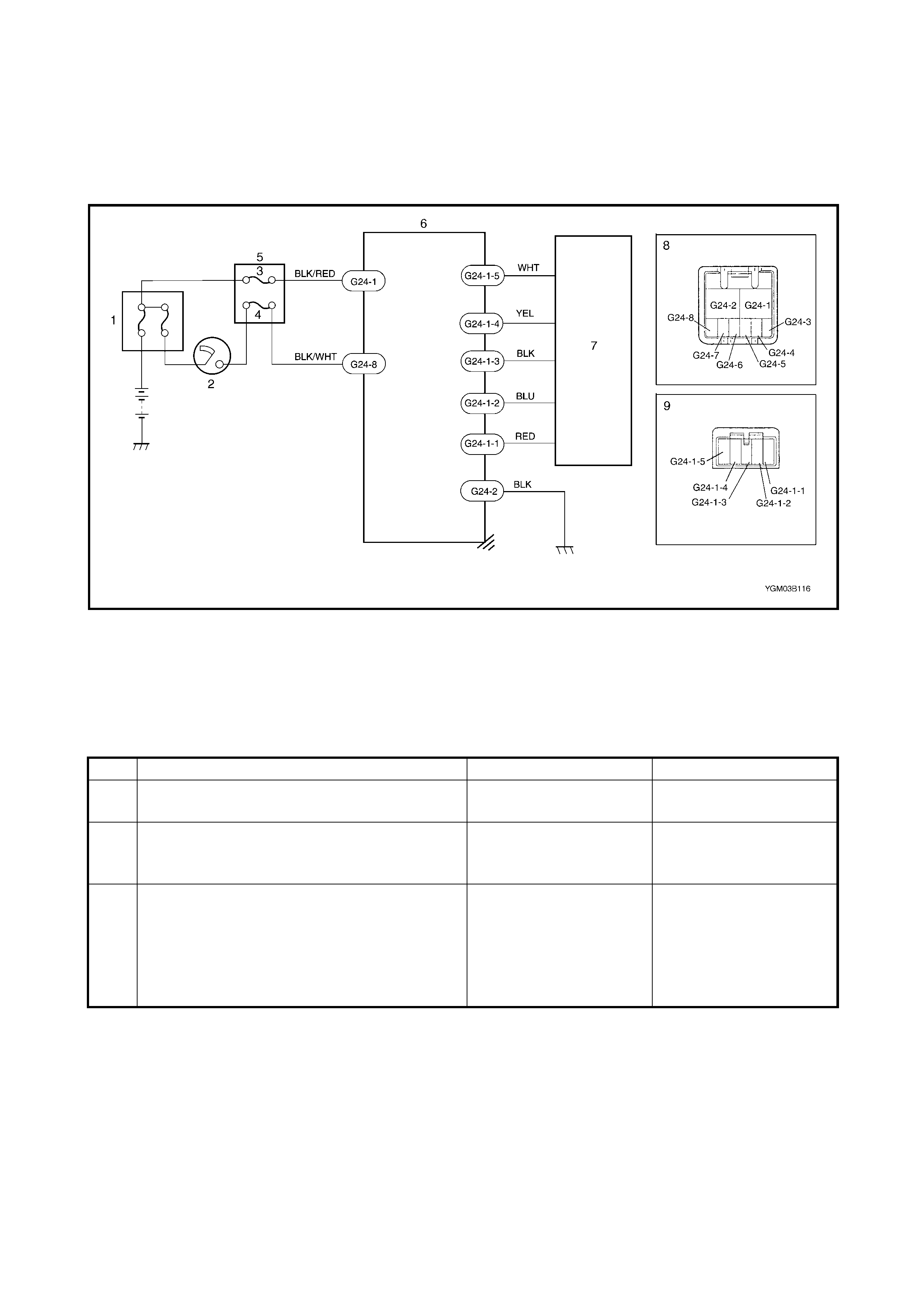
Legend
1. Main fuse box 5. Circuit fuse box 8. Connector G24
2. Ignition switch 6. P/S control module (viewed from harness side)
3. P/S fuse (30A) 7. Torque sensor 9. Connector G24-1
4. IG fuse (15A) (viewed from harness side)
Step Action Yes No
1. 1. Was SYSTEM CHECK FLOW TABLE
performed? Go to STEP 2. Go to 3.3 SYSTEM
CHECK FLOW TABLE.
2. 1. Is DTC C1114 (DTC No.14) or C1116
(DTC No.16) indicated? Go to flow table corre-
sponding to each DTC
No.
Go to STEP 3.
3. 1. Check proper connection for connector
(G24-1) to P/S control module.
2. If OK, check t orque se ns or and its circuit.
Refer to 4.4 TORQUE SENSOR in this
Section.
3. Is torque sensor in good condition?
Substitute a known-good
P/S control module and
recheck.
Replace steering column
assembly and recheck.
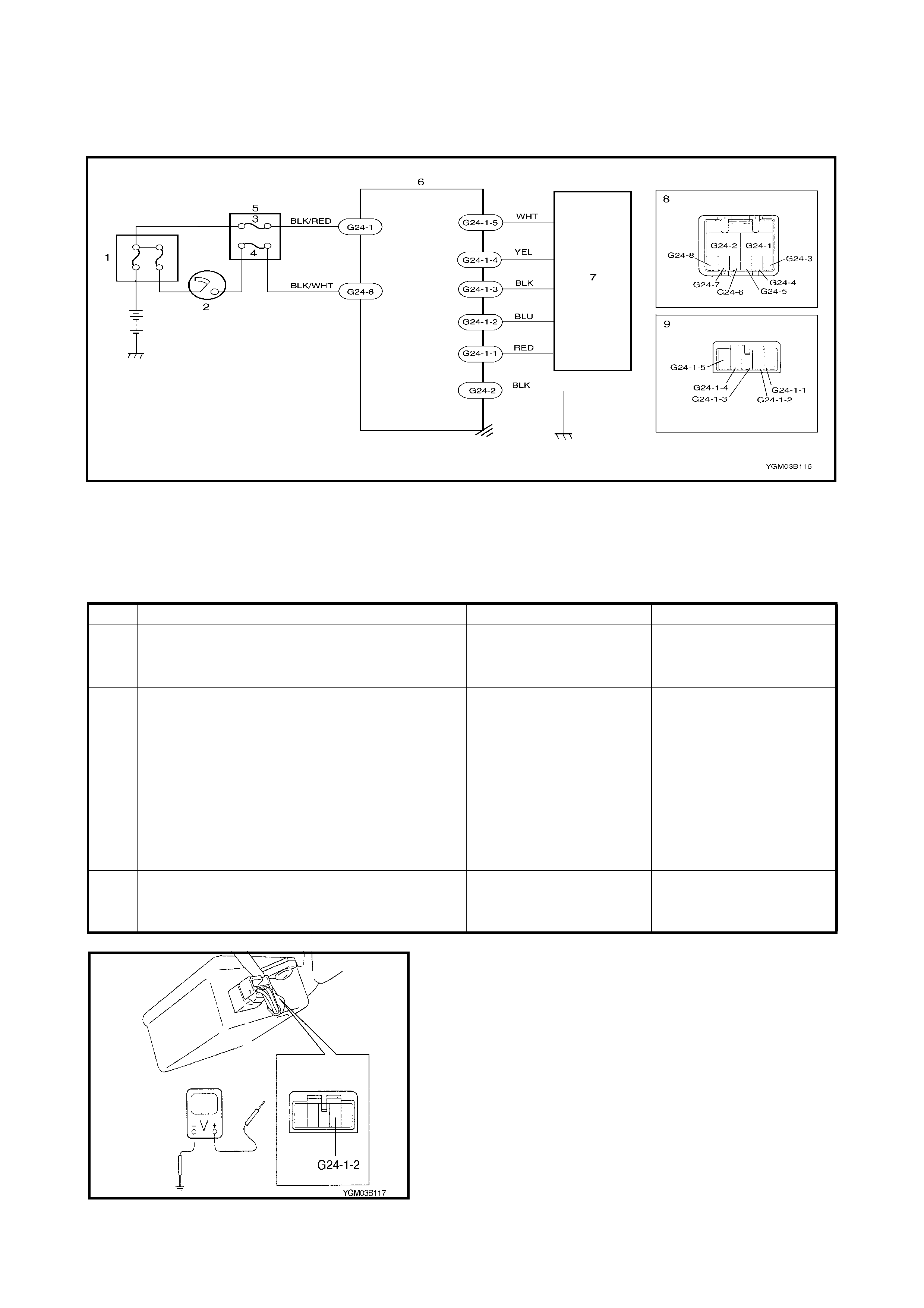
3.15 DTC C1114 (DTC NO.14) TORQUE SENSOR 5V
POWER SUPPLY CIRCUIT FAILURE
Legend
Figure 1 for Step 2
1. Main fuse box 5. Circuit fuse box 8. Connector G24
2. Ignition switch 6. P/S control module (viewed from harness side)
3. P/S fuse (30A) 7. Torque sensor 9. Connector G24-1
4. IG fuse (15A) (viewed from harness side)
Step Action Yes No
1. Was SYSTEM CHECK FLOW TABLE per-
formed? Go to STEP 2. Go to 3. 3 SYSTEM
CHECK FLOW TABLE in
this Section.
2. 1. Remove steering column hole cover.
2. Check proper connection for connector
(G24-1) to P/S control module.
3. If OK, turn ignition switch ON.
4. Check voltage between G24-1-2 (BLU
wire) terminal of connector (G24-1) and
body ground with connector (G24-1)
connected to P/S control module.
Is it about 5 V?
Go to STEP 3. Repair high resistance,
open or short to power
circuit or ground in 5V
power supply (BLU wire)
circuit.
3. 1. Check torque sensor and its circuit. Refer
to 4.4 TORQUE SENSOR in this Section.
Is torque sensor in good condition?
Substitute a known-good
P/S control module and
re-check.
Replace ste ering colu mn
assembly and recheck.
3.16 DTC C1116 (DTC NO.16) TORQUE SENSOR
8V POWER SUPPLY CIRCUIT FAILURE
Legend
Figure 1 for Step 2
1. Main fuse box 5. Circuit fuse box 8. Connector G24
2. Ignition switch 6. P/S control module (viewed from harness side)
3. P/S fuse (30A) 7. Torque sensor 9. Connector G24-1
4. IG fuse (15A) (viewed from harness side)
Step Action Yes No
1. Was SYSTEM CHECK FLOW TABLE
performed?Go to STEP 2. Go to 3.3 SYSTEM
CHECK FLOW TABLE in
this Section.
2. 1. Remove steering column hole cover.
2. Check proper connection for connector
(G24-1) to P/S control module.
3. If OK, turn ignition switch ON.
4. Measur e voltage between G24-1-1 (R ED
wire) terminal of connector (G24-1) and
body ground with connector (G24-1)
connec ted to P/S co ntrol modul e.
Is it about 8 V?
Go to STEP 3. Repair high resistance,
open or short to power
circuit or ground in 8V
power supply (RED wire)
circuit.
3. 1. Check torque sensor and its circuit. Refer
to 4.4 TORQUE SENSOR in this Section.
Is torque sensor in good condition?
Substitute a known-good
P/S control module and
recheck.
Replace steering column
assembly and recheck.
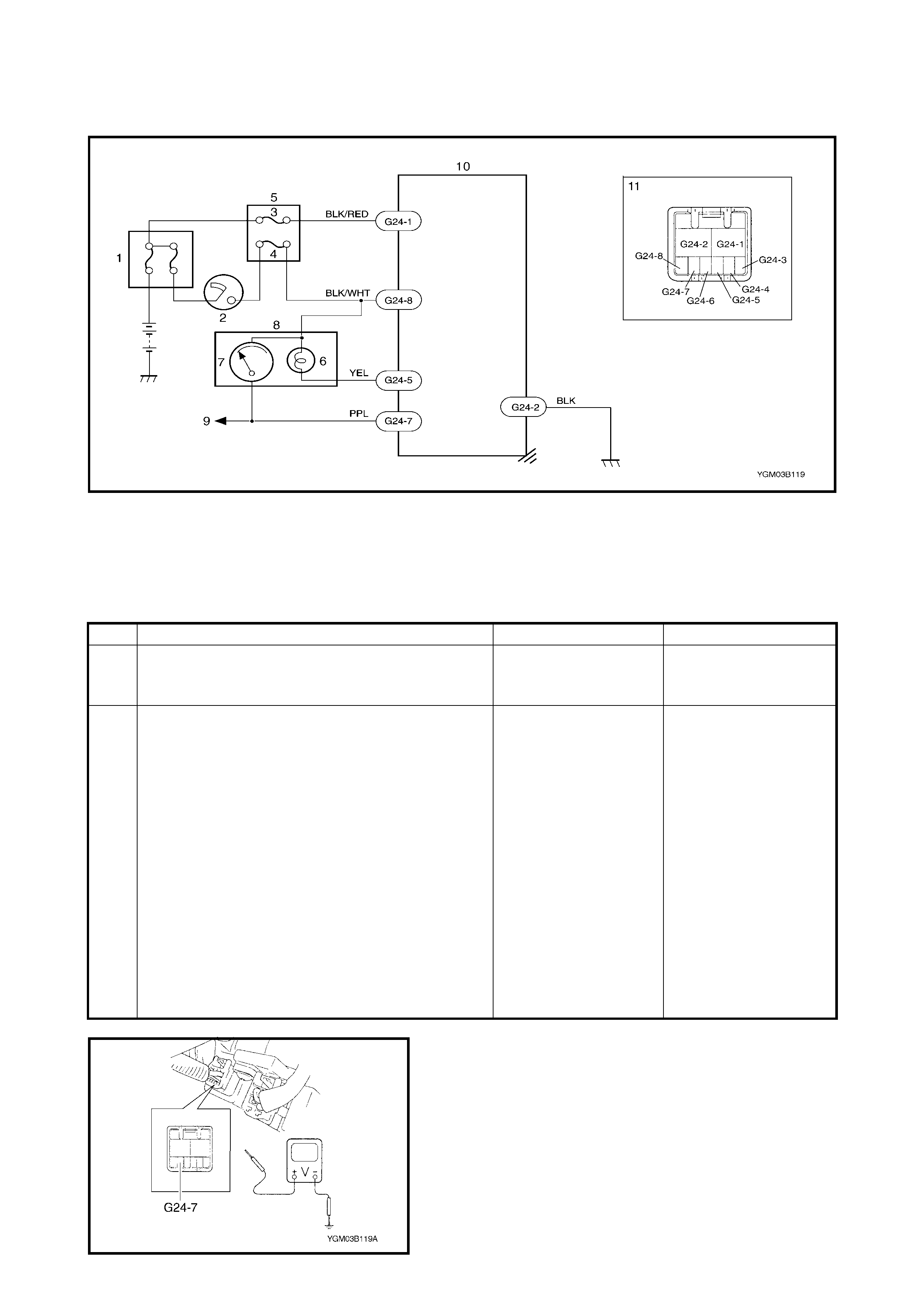
3.17 DTC C1121/C1123/C1124 (DTC NO.21/23/24 ) VSS CIRCUIT FAILURE
Legend
Figure 1 for Step 2
1. Main fuse box 5. Circuit fuse box 9. To VSS
2. Ignition switch 6. EPS warning light 10. P/S control module
3. P/S fuse (30A) 7. Speedometer 11. Connector G24
(viewed from harness side)
4. IG fuse (15A) 8. Com binati on mete r
Step Action Yes No
1Was SYSTEM CHECK FLOW TABLE performed? Go to STEP 2. Go to 3.3 SYSTEM
CHECK FLOW TA BLE
in this Section.
21) Ignition switch OFF.
2) Remove s teering column lower cover.
3) Disconnect connector (G24) from P/S control
module.
4) Check prope r connec ti on to P/S co ntrol mod-
ule at G24-7 (PPL wire) terminal.
5) If OK, connect voltmeter between G24-7 (PPL
wire) terminal and body ground with connector
(G24 ) connec te d.
6) Hoist rear end of vehicle and lock rear right
tyre.
7) Turn rear left tyre quickly with ignition switch
ON.
Does voltmeter indicate deflection between 0 – 1 V
and 9 – 11 V a few times while tyre is turned one
revolution?
Check intermittent trou-
ble. Refer to Section
OA INTERMITTENT
AND POOR CONNEC-
TION.
If OK, substitute a
known-good P/S con-
trol module and
recheck.
Repair VSS or its (PPL
wire) circuit.
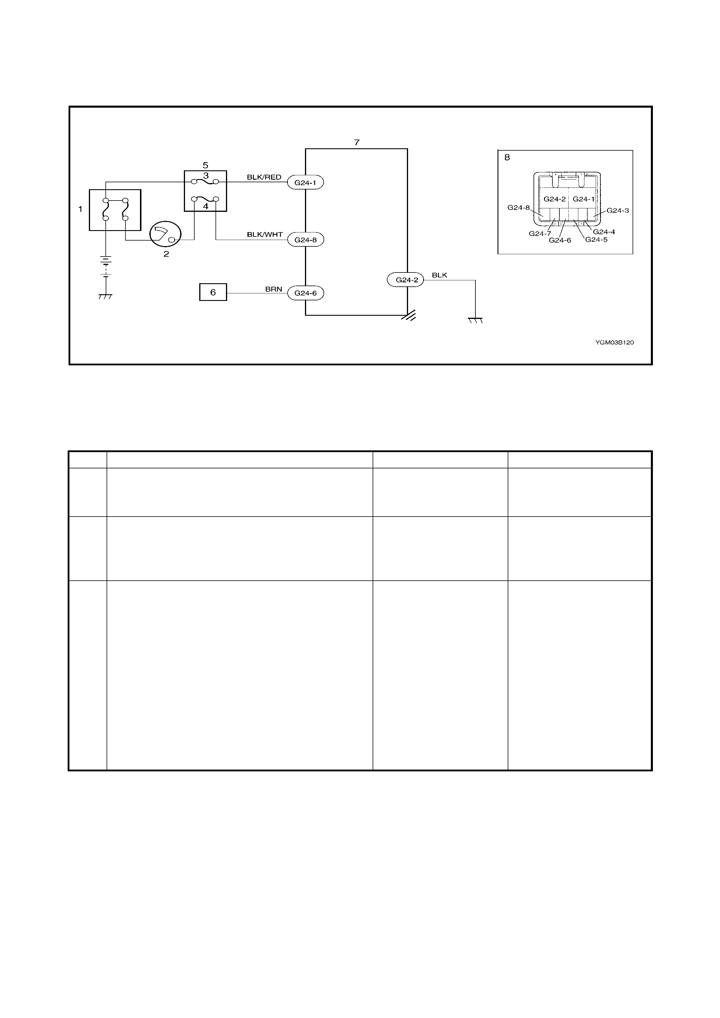
3.18 DTC C1122 (DTC NO.22) ENGINE SPEED SIGNAL CIRCUIT FAILURE
Legend
1. Main fuse box 4. IG fuse (15A) 7. P/S control module
2. Ignition switch 5. Circuit fuse box 8. Connector G24
3. P/S fuse (30A) 6. ECM (viewed from harness side)
Step Action Yes No
1. Was SYSTEM CHECK FLOW TABLE
performed? Go to STEP 2. Go to 3.3 SYSTEM
CHECK FLOW TABLE in
this Section.
2. 1. Recheck DTC with engine running.
Is DTC C1122 (DTC No.22) indicated? Go to STEP 3. It is nothing abnormal for
DTC C1122 (DTC
No.22). P/S system is in
normal condition.
3. 1. Check proper connection to P/S control
module and ECM at each BRN wire
terminal (P/S control module side: G24-6
terminal, ECM side: Refer to Section 6E1
ENGINE AND EMISSION CONTROL
SYSTEM), then check intermittent trouble.
Refer to Section 0A INTERMITTENT
TROUBLE.
2. If they are OK, check high resistance, open
or short to power circuit or ground in BRN
wire circuit.
Is check result in good condition?
Substitute a known-
good P/S control mod-
ule and recheck.
Repair.
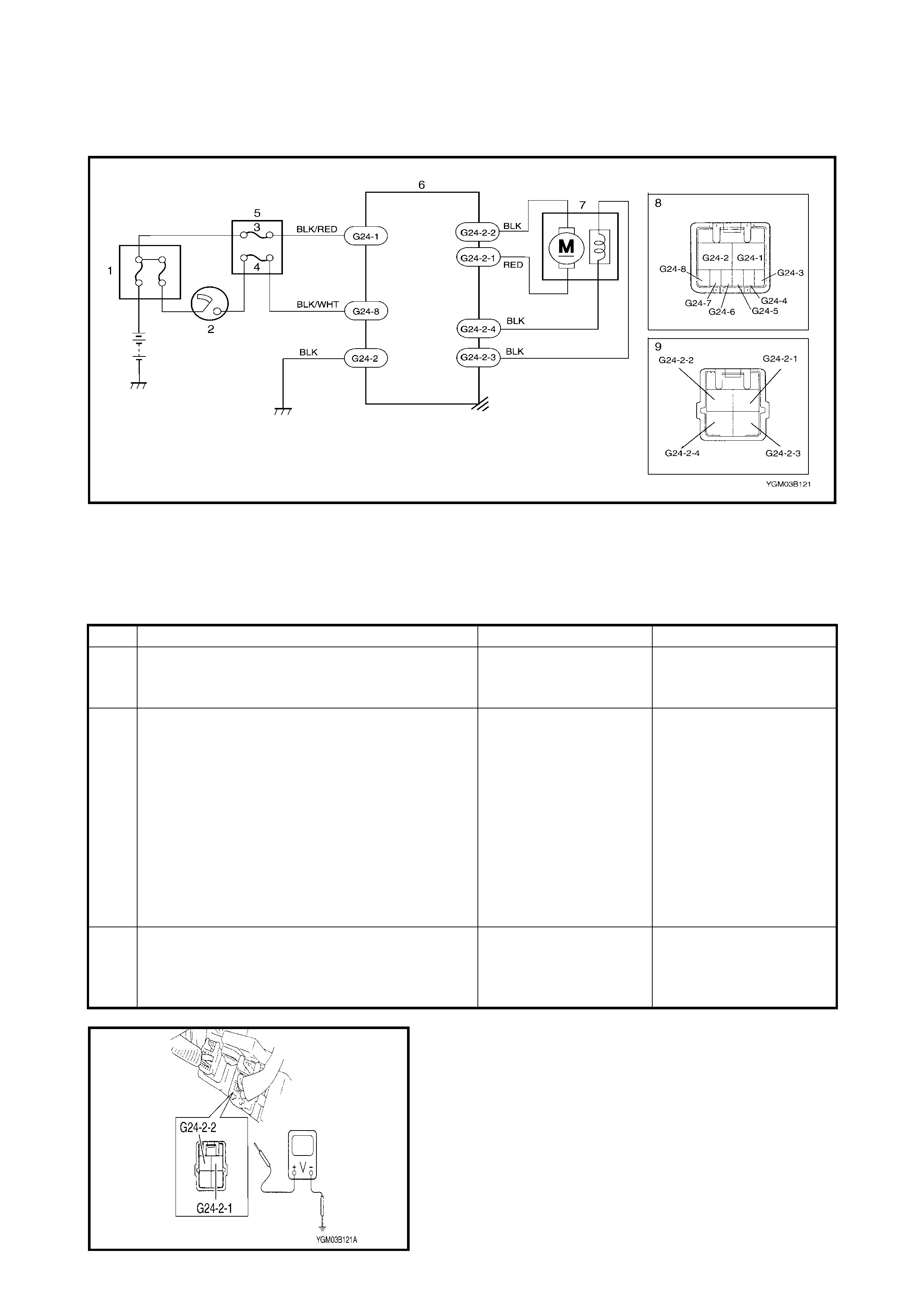
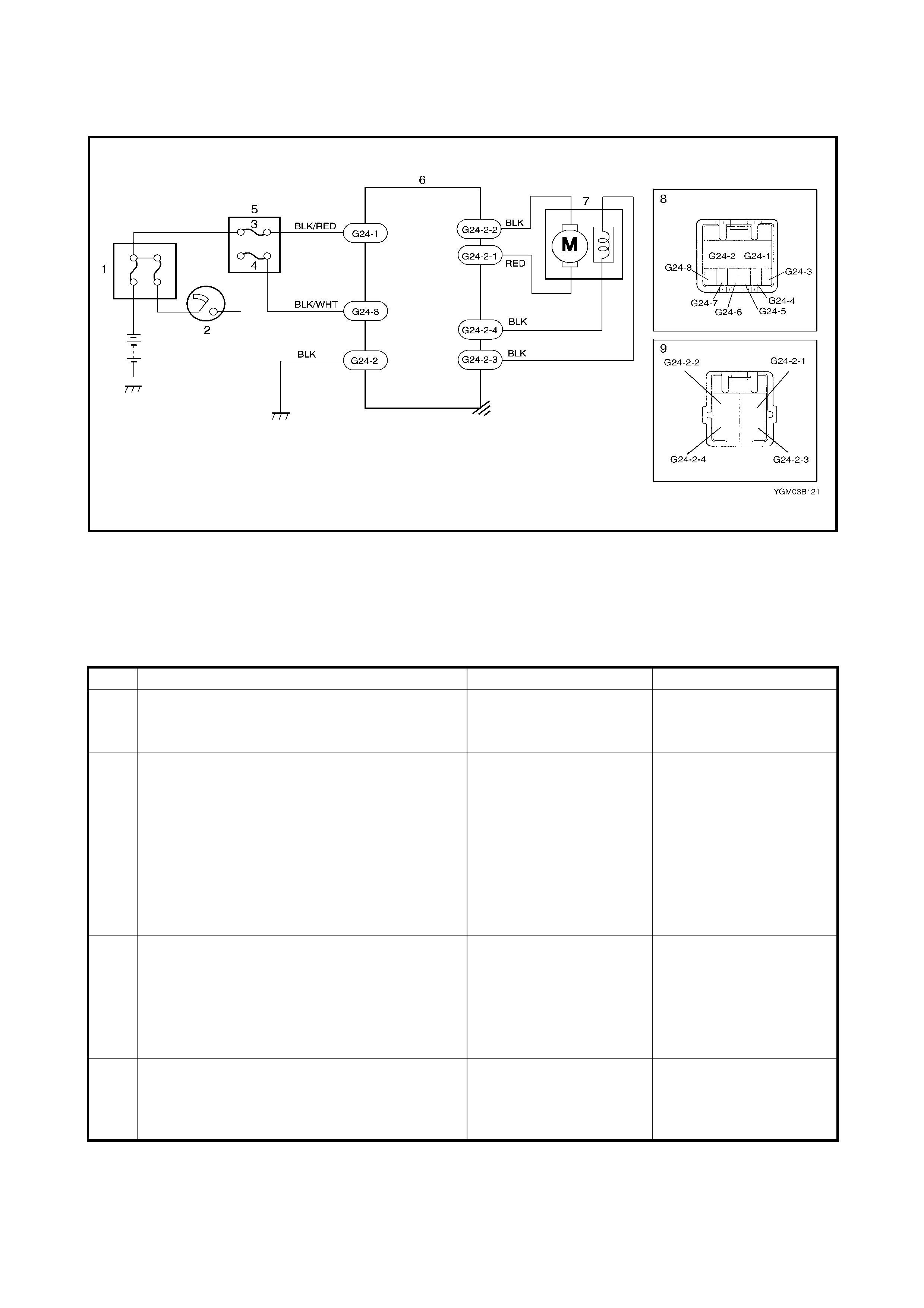
3.19 DTC C1141/C1142/C1143/C1144/C1145 (DTC NO.41/42/43/44/45)
MOTOR CIRCUIT FAILURE
Legend
Figure 1 for Step 2
1. Main fuse box 5. Circuit fuse box 8. Connector G24
(viewed from harness side)
2. Ignition switch 6. P/S control module
3. P/S fuse (30A) 7. Motor and clutch 9. Connector G24-2
(viewed from harness side)
4. IG fuse (15A)
Step Action Yes No
1. Was SYSTEM CHECK FLOW TABLE
performed? Go to STEP 2. Go to 3.3 SYSTEM
CHECK FLOW TABLE in
this Section.
2. 1. Remove steering column hole cover.
2. Check proper connection for 4-terminals
connector (G24-2) to P/S control module.
3. If OK, start engine.
4. Check voltage between G24-2-2 (BLK
wire) terminal and body ground and G24-
2-1 (RED wire) terminal and body ground
with connector (G24-2) connected to P/S
control module.
Are they 5 – 7 V with the steering wheel held at
straight ahe ad pos ition?
Go to STEP 3. Repair poor connection,
high resistance, open or
short to power circuit or
ground in G24-2-2 (BLK
wire) or G24-2-1 (RED
wire) circuit.
3. 1. Check motor and its circuit. Refer to 4.5
MOTOR ASSEMBLY (WITH CLUTCH
INCORPORATED in this Section.
Is motor and clutch in good condition?
Substitute a known-
good P/S control mod-
ule and recheck.
Replace steering column
assembly and recheck.
3.20 DTC C11 51 (DTC NO.51) CLUTCH CIRCUIT FAILURE
Legend
1. Main fuse box 5. Circuit fuse box 8. Connector G24
(viewed from harness side)
2. Ignition switch 6. P/S control module
3. P/S fuse (30A) 7. Motor and clutch 9. Connector G24-2
(viewed from harness side)
4. IG fuse (15A)
Step Action Yes No
1. Was SYSTEM CHECK FLOW TABLE
performed?Go to STEP 2. Go to 3.3 SYSTEM
CHECK FLOW TABLE in
this Section.
2. 1. Remove steering column hole cover.
2. Check proper connection for connector
(G24-2) to P/S control module.
3. If OK, start engine.
4. Check voltage between G24-2-4 (BLK
wire) terminal and body ground with
connector (G24-2) connected to P/S
control module.
Is it 0 V?
Go to STEP 3. Repair poor connection,
high resistance, open or
short to power circuit or
ground in G24-2-4 (BLK
wire) ci rcuit.
3. 1. Check voltage between G24-2-3 (BLK
wire) terminal and body ground with
connector (G24-2) connected to P/S
control module.
Is it 10 – 14 V with steering wheel held at
straight ahead position?
Go to STEP 4. Repair poor connection,
high resistance, open or
short to power circuit or
ground in G24-2-3 (BLK
wire) ci rcuit.
4. 1. Check motor and its circuit. Refer to 4.5
MOTOR ASSEMBLY (WITH CLUTCH
INCORPORATED).
Is motor and clutch in good condi tio n?
Substitute a known-good
P/S control module and
recheck.
Replace steering column
assembly and recheck.
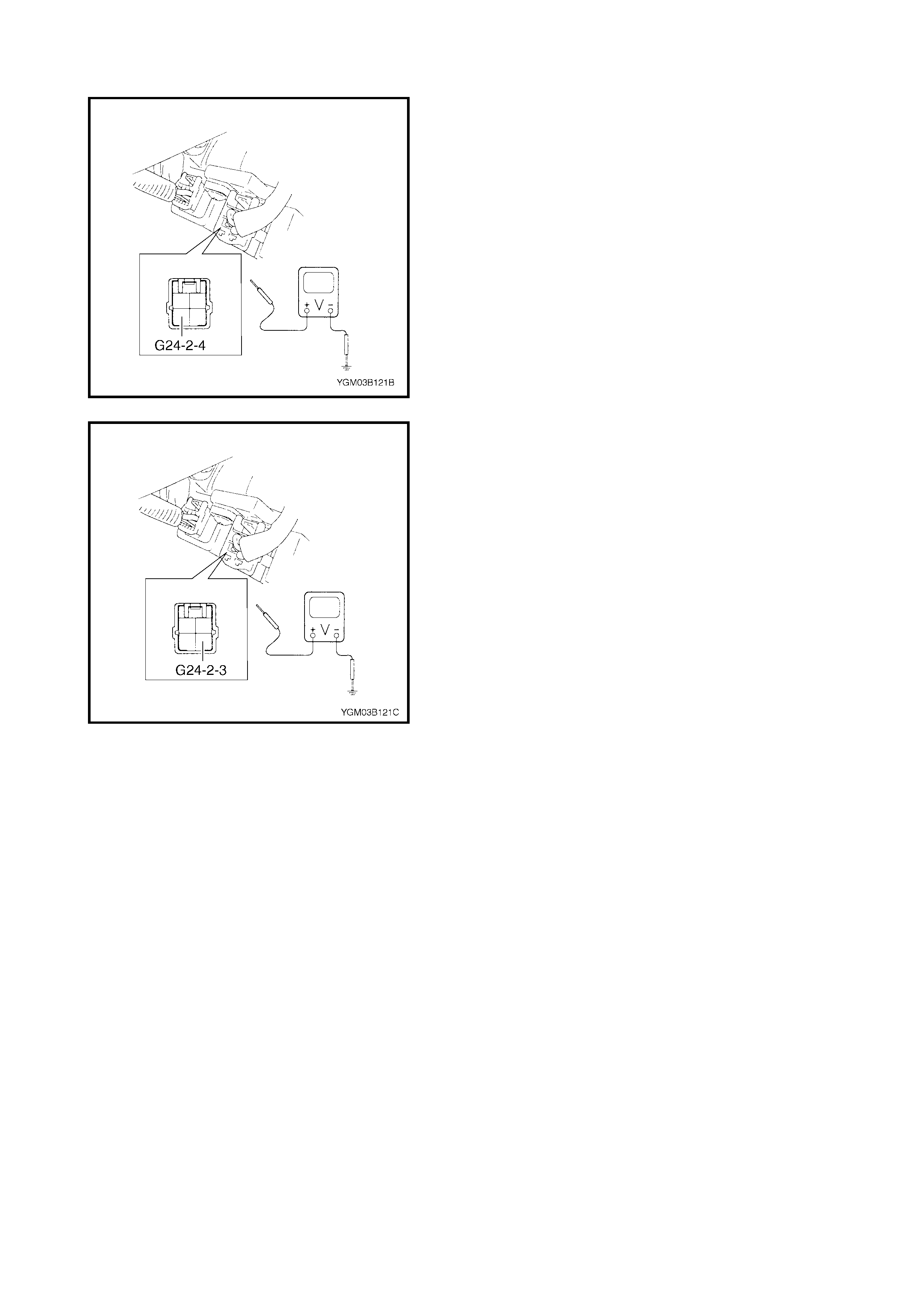
Figure 1 for Step 2
Figure 2 for Step 3
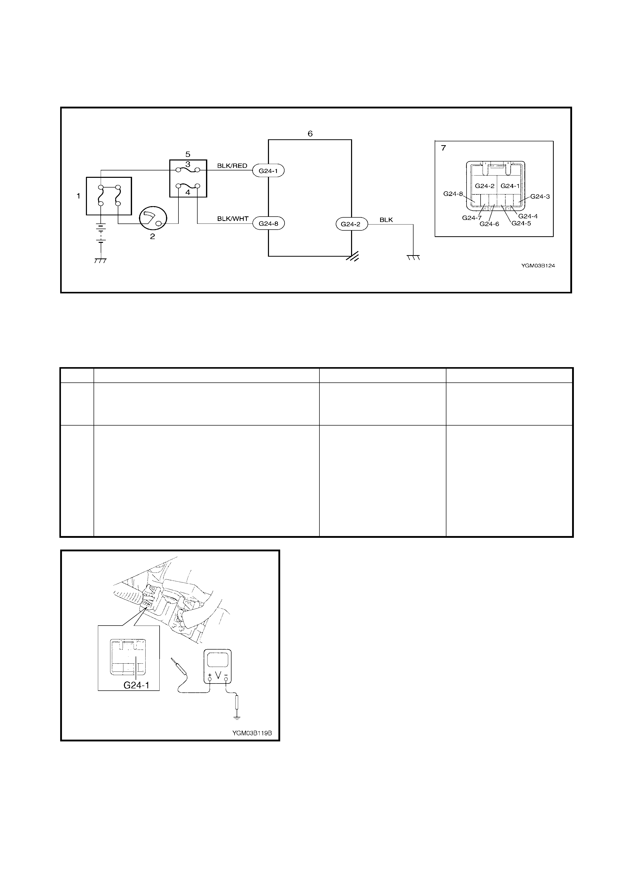
3.21 DTC C1153(DTC NO.53) P/S CONTROL MODULE
POWER SUPPLY CIRCUIT FAILURE
Legend
Figure 1 for Step 2
3.22 DTC C1152/C1154/C1155 (DTC NO.52/54/55) P/S CONTROL MODULE FAILURE
Substitute a known-good P/S control module and recheck.
1. Main fuse box 4. IG fuse (15A) 7. Connector G24
(viewed from harness side)
2. Ignition switch 5. Circuit fuse box
3. P/S fuse (30A) 6. P/S control module
Step Action Yes No
1. Was SYSTEM CHECK FLOW TABLE
performed?Go to STEP 2. Go to 3.3 SYSTEM
CHECK FLOW TABLE in
this Section.
2. 1. Remove steering column hole cover.
2. Check P/S fuse and proper connection to
P/S control module at G24-1 (BLK/WHT
wire) terminal.
3. If OK, check voltage between G24-1
termina l and body gro und with con nector
(G24) connected to P/S control module.
Is it 10 – 14 V?
Check intermittent trou-
ble. Refer to Section 0A
INTERMITTENT AND
POOR CONNECTION.
If OK, substitute a known-
good P/S control module
and rechec k.
Repair poor connection
or high resistance in G24-
1 (BLK/RED wire) circuit.

3.23 TROUBLE DIAGNOSIS
(FOR TROUBLE NOT INDICATED BY ON-BOARD DIAGNOSTIC SYSTEM)
This section describes trouble diagnosis of the P/S system parts when the fault is not indicated by the on-
board dia gno sti c system (sel f- di agno st ic function ).
When there is no malfunction indicated by the on-board diagnostic system (self-diagnosis function) and the
basic steering parts described in the diagnostic table, refer to Section 3, 1.1 GENERAL DIAGNOSIS, are all in
good condition, check the following power steering system parts which may be a possible cause for faulty
steering.
Condition Possible Cause Correction
Steering wheel feels
heavy (Perform
STEERING FORCE
INSPECTION before
diagnosis.)
Steering wheel installed improperly (twisted) Install steering wheel correctly.
Poor performance of torque sensor Check torque sensor. Refer to
4.4 TORQUE SENSOR in this
Section.
Poor performance of motor and clutch Check motor and clutch. Refer to
4.5 MOTOR ASSEMBLY (WITH
CLUTCH INCORPORATED.
Faulty steering column Replace.
Poor performance of VSS Check VSS. Refer to Section 6E1
ENGINE AND EMISSION
CONTROL SYSTEM.
Vehicle pulls to one
side during straight
driving
Poor performance of torque sensor Check torque sensor. Refer to
4.4 TORQUE SENSOR in this
Section.
Poor recovery from
turns Poor performance of torque sensor Check torque sensor. Refer to
4.4 TORQUE SENSOR in this
Section.
Faulty steering column Replace.
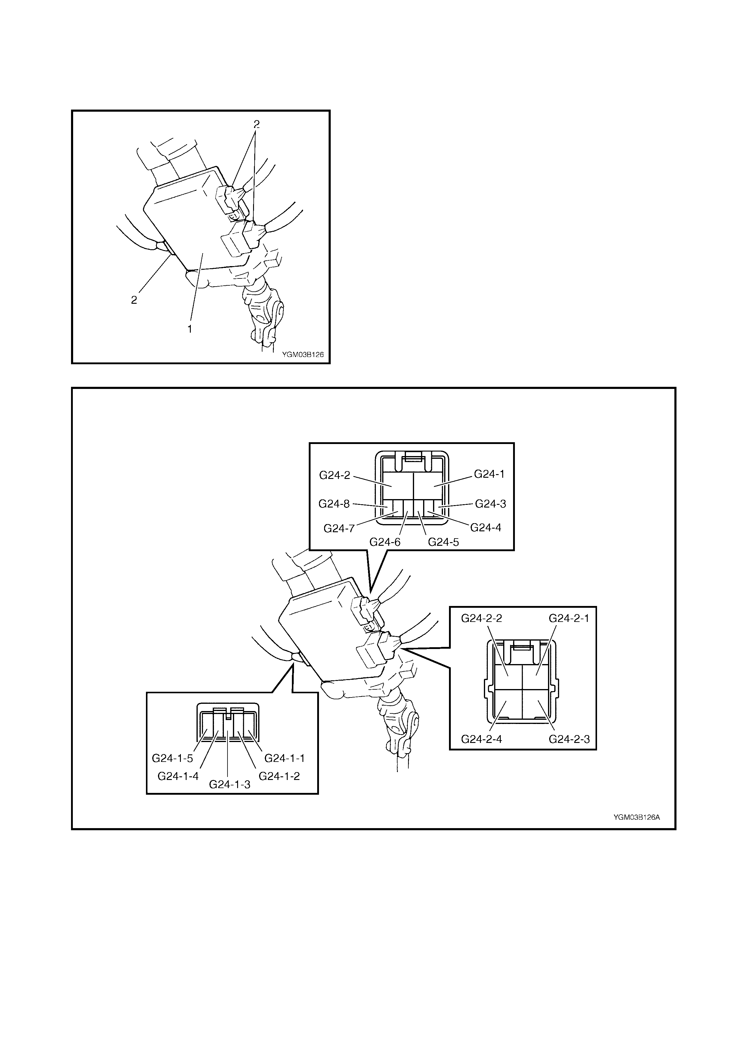
3.24 INSPECTION OF THE P/S CONTROL MODULE AND ITS CIRCUITS
The P/S co ntrol modul e (1) and its circuits can be c hecked
at the P/S control module wiring connectors (2) by measur-
ing voltage and resistance.
CAUTION: P/S control module cannot be checked by
itself. It is strictly prohibited to connect a voltmeter or
ohmmeter to the P/S control module with the connec-
tor disconnected from it.
VO LTAGE CHECK
1. Remove steering column hole cover with ignition
switch in OFF position.
2. Chec k voltage at eac h te rm in al w ith co nnec to rs ( 2) st il l
connected to the P/S control module.
NOTE: As each terminal voltage is affected by the battery
voltage, confirm that it is 11V or more when the ignition
switch is ON.

NOTE: ✱: The voltage of this circuit may fail to check by voltmeter. If so, use an oscilloscope.
TERMINAL
NO. CIRCUIT NORMAL VOLTAGE CONDITION
G24-2 Ground – –
G24-1 P/S control module
power supply from battery 10 – 14V –
G24-8 P/S control module
power supp ly from igni-
tion switch
10 – 14V Ignition switch ON
G24-7 VSS ✱ Indicator
deflection repeated
0 – 1V and 9 – 11V
Ignition switch ON
Front left tyre turned quickly with
right tyre locked
G24-6 Engine speed signal ✱ Indicator
deflection repeated
0 – 1V and 10 – 14V
Engine idling
G24-5 EPS light 0V EPS warning lamp ON
G24-4 Diagnosis switch terminal 4.6V Ignition switch ON
G24-3 Data link connector – –
G24-2-2 Motor output 2 5 – 7V Engine idling and steering wheel
held at straight ahead position
G24-2-1 Motor output 1 5 – 7V Engine idling and steering wheel
held at straight ahead position
G24-2-4 Clutch output 2 0V –
G24-2-3 Clutch output 1 10 – 14V Engine idling
G24-1-5 Torque sensor (Main) About 2.5V Ignition switch ON and steering
wheel held at straight ahead posi-
tion
Check voltage between G24-1-5
and G24-1- 3 terminals
G24-1-4 Torque sensor (Sub) About 2.5V Ignition switch ON and steering
wheel held at straight ahead posi-
tion
Check voltage between G24-1-4
and G24-1- 3 terminals
G24-1-3 Torque sensor (GND) 0V –
G24-1-2 5V power supply
for torque sensor About 5V Ignition switch ON
Check voltage between G24-1-2
and G24-1- 3 terminals
G24-1-1 8V power supply
for torque sensor About 8V Ignition switch ON
Check voltage between G24-1-1
and G24-1- 3 terminals
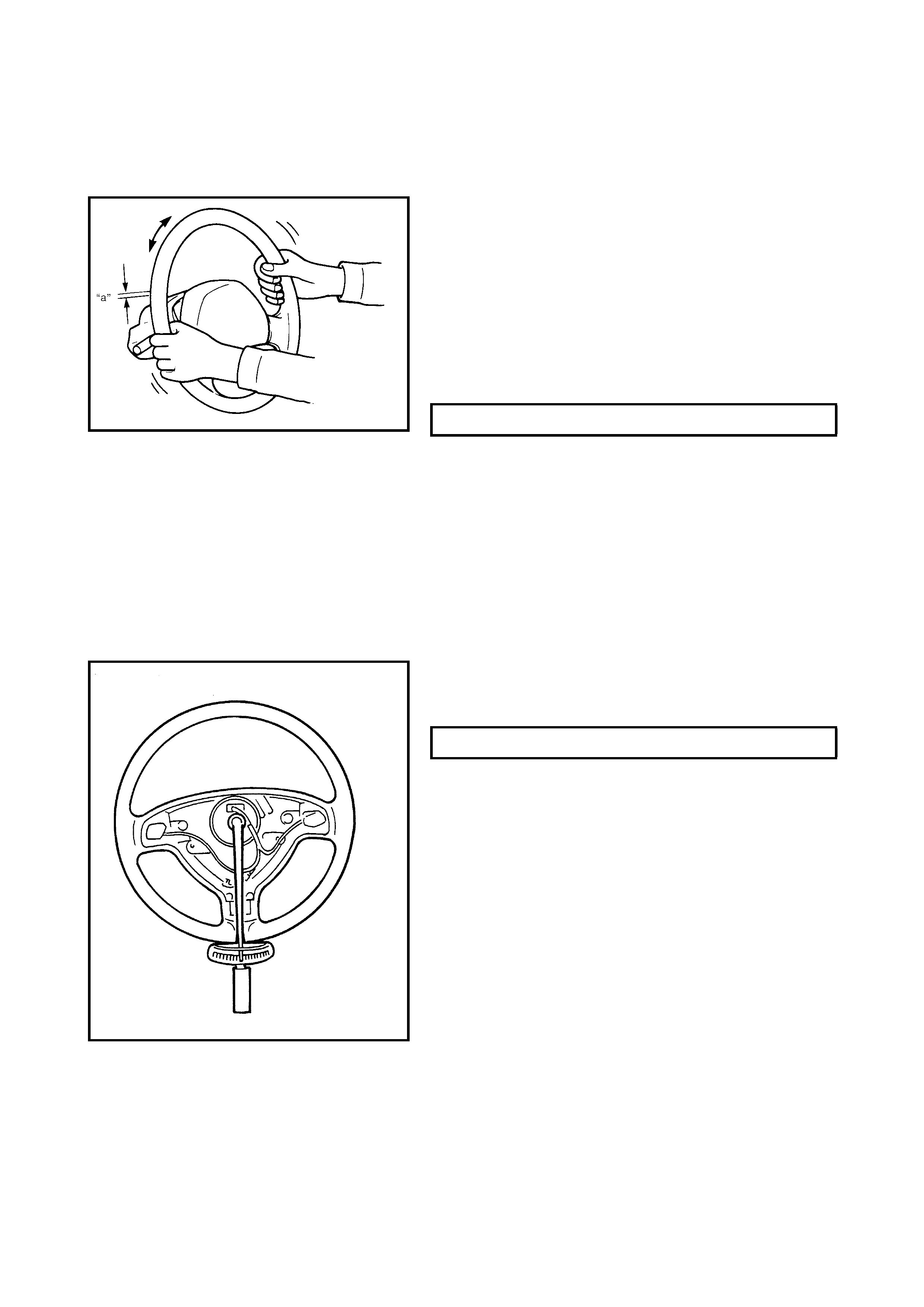
3.25 STEERING WHEEL PLAY INSPECTION
Check the steering wheel for looseness or rattle by trying to
move it in its shaft direction and lateral direction.
If found defective, repair or replace.
Check steering wheel play, holding the vehicle in a straight
forward position on the ground and with the engine not run-
ning.
If steering wheel play is not within specification, inspect as
follows and replace if found defective.
• Tie rod end ball stud for wear
• Lower ball joint for wear
• Steering shaft joint for wear
• Steering pinion or rack gear for wear or breakage
• Each part for looseness
3.26 STEERING FORCE INSPECTION
1. Place vehicle on level road and set steering wheel in
straight-ahead position.
2. Check that tyre inflation pressure is as specified.
(Refer to the TYRE PLACARD on the vehicle.)
3. Remove drivers airbag (inflator) module, refer to
Section 3C, 3.2 DRIVER AIRBAG (INFLATOR)
MODULE REMOVAL.
4. Start engine.
5. With the engine idling, measure the steering force by
placing torque wrench on steering wheel nut and
turning torque wrench.
6. Install driver airbag (inflator) module, refer to
Section 3C, 3.2 DRIVER AIRBAG (INFLATOR)
MODULE INSTALLATION.
STEERING WHEEL PLAY (a) 0 - 30 mm
STEERING FORCE LESS THAN 6.4 Nm
4. ON-VEHICLE SERVICE
4.1 STEERING COLUMN ASSEMBLY
REMOVAL
Refer to Section 3C STEERING WHEEL AND COLUMN for removal and installation of steering column
assembly but perform the following steps first.
• Remove steering hole cover.
• Disconnect all couplers from the P/S control module.
CAUTION: Never disassemble the steering column assembly, remove the torque sensor or motor
assembly (with clutch incorporated). Performing any of these prohibited services will affect original
performance of the EPS system.
4.2 CHECKING STEERING COLUMN ASSE MBLY AND LOWER SHAFT FOR
ACCIDENT DA MAGE
NOTE: Vehicles involved in accidents resultin g in body damage , where steering column has been impacted
(or airbag deployed) may have a damaged or misaligned steering column.
CHECKING PROCEDURE
Refer to Section 3C, 3.9 CHECKING STEERING COLUMN ASSEMBLY AND LOWER SHAFT FOR
ACCIDENT DAMAGE.
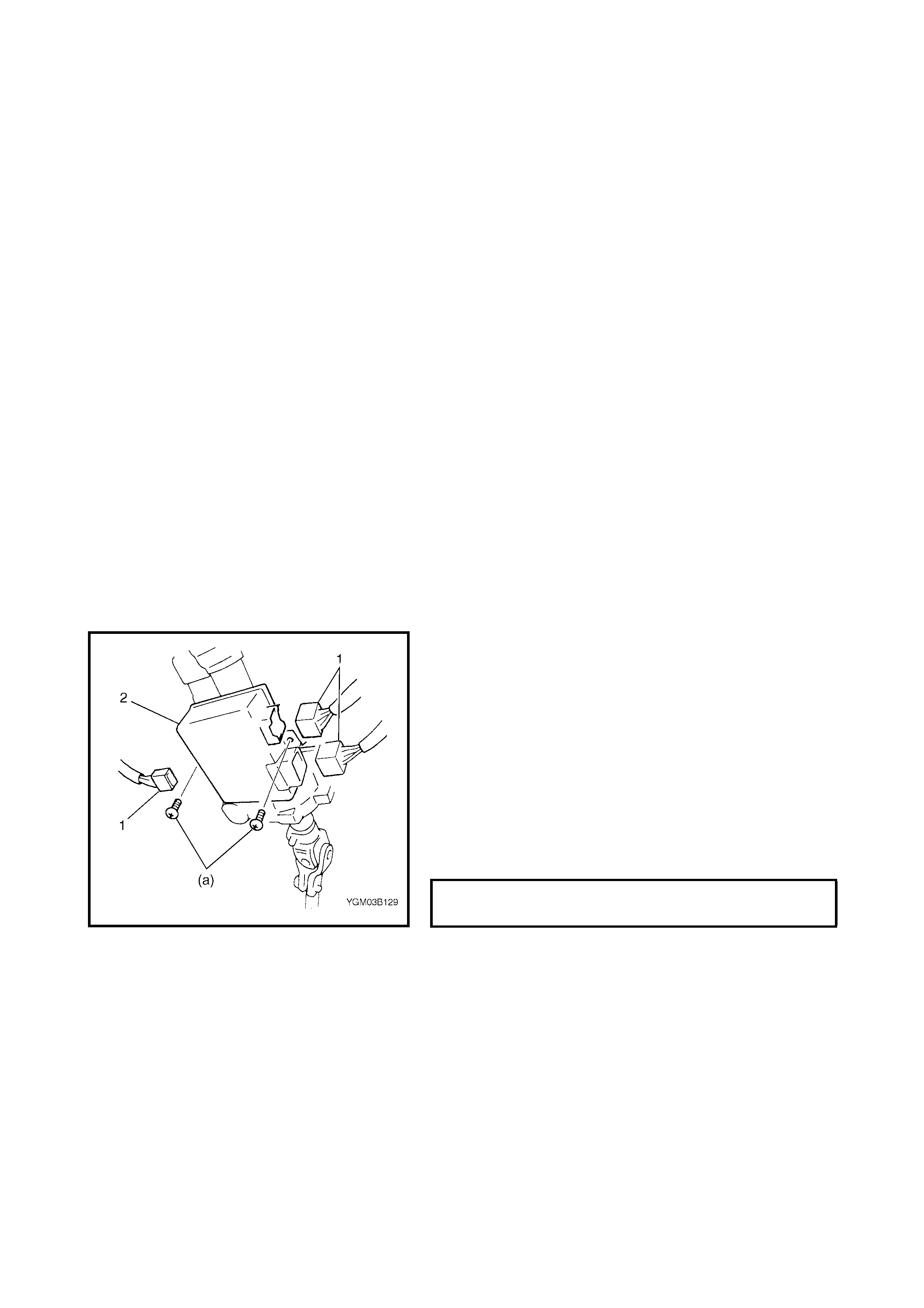
4.3 P/S CONTROL MODULE
REMOVAL
1. Disconnect negative cable at battery.
2. Remove steering column hole cover.
3. Disconnect connectors (1) from the P/S control
module.
4. Remove the P/S control module (2) from the steering
column assembly.
INSTALLATION
Reverse removal procedure for installation, noting the fol-
lowing.
• Tighten P/S control module screw (a) to specified
torque
P/S CONTROL MODULE SCREW
TORQUE SPECIFICATION (a) 3 Nm
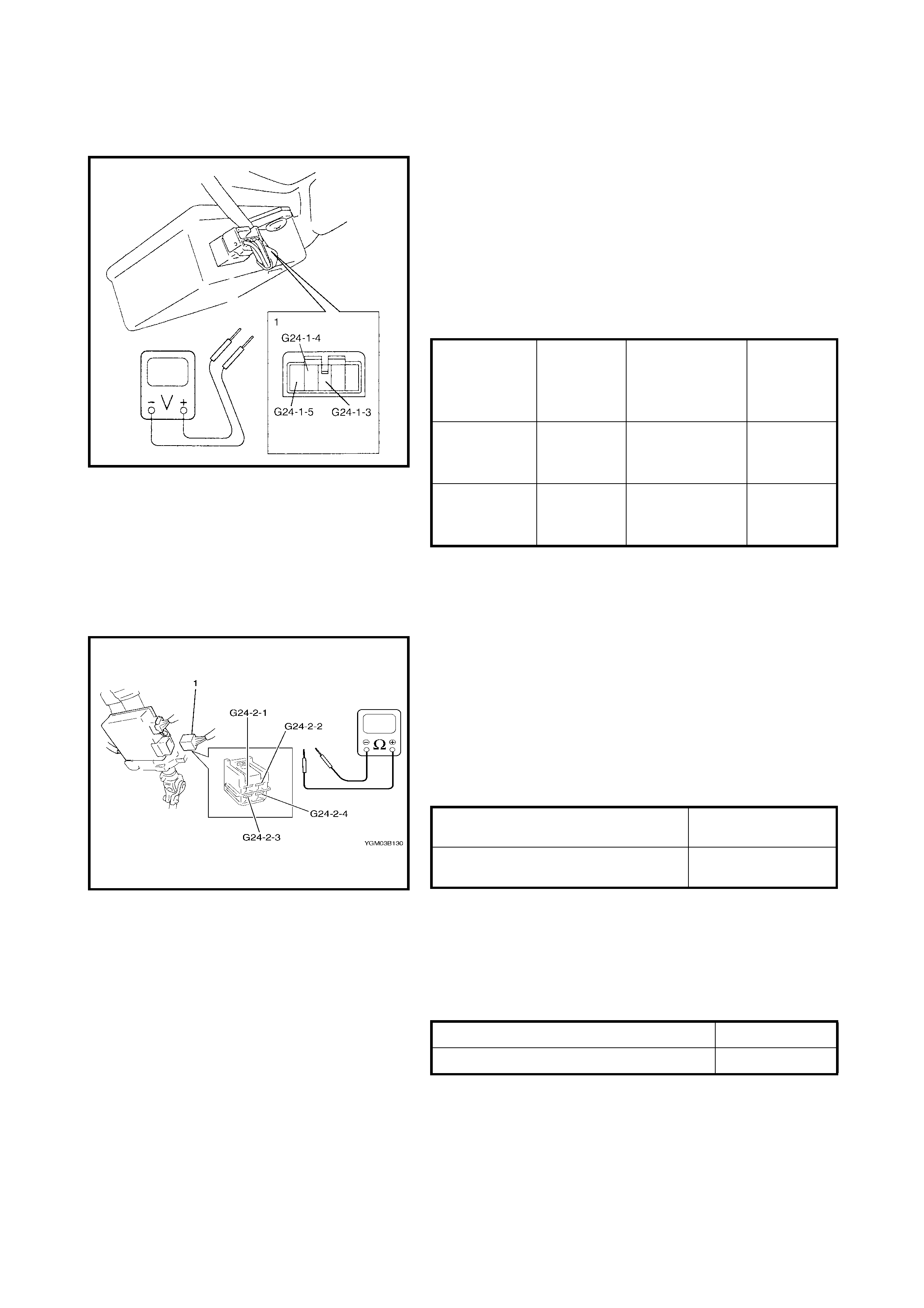
4.4 TORQUE SENSOR
ON-VEHICLE INSPECTION
1. Remove steering column hole cover.
2. Turn ignition switch to ON position
3. With the engine not running, check the voltage
between terminals of the torque sensor connector
while still connected to the P/S control module.
If check result is not satisfactory, replace steering
column assembly.
Torque sensor specification
4.5 MOTOR ASSEMBLY (WITH CLUTCH INCORPORATED)
ON-VEHICLE INSPECTION
1. Remove steering column hole cover.
2. With the ignition switch in OFF position, disconnect
motor and clutch connector (1) from the P/S control
module.
3. Check the resistance between terminals of motor and
clutch connector (1).
If check result is not as specified below, replace
steering column assembly.
Motor and clutch circuit resist ance
4. Chec k continui ty between te rminal o f motor and clutch
connector (1) and body ground.
If check result is not as specified below, replace
steering column assembly.
Motor and clutch circuit resistance (to bo dy gr ound)
Steering
wheel
turned
fully left
Steering wheel
held at straight
ahead position
Steering
wheel
turned fully
right
Main sensor
(G24-1-4 –
G24-1-3) 1.5 V below About 2.5 V Above 3.5 V
Sub sensor
(G24-1-5 –
G24-1-3) 1.5 V below About 2.5 V Above 3.5 V
G24-2-2 and G24-2 -1
(For motor) About 1 Ω
G24-2-4 and G24-2 -3
(For clutch) About 12 Ω
(at 20°C (68°F))
G24-2-4 and body ground No continuity
G24-2-2 and body ground No continuity
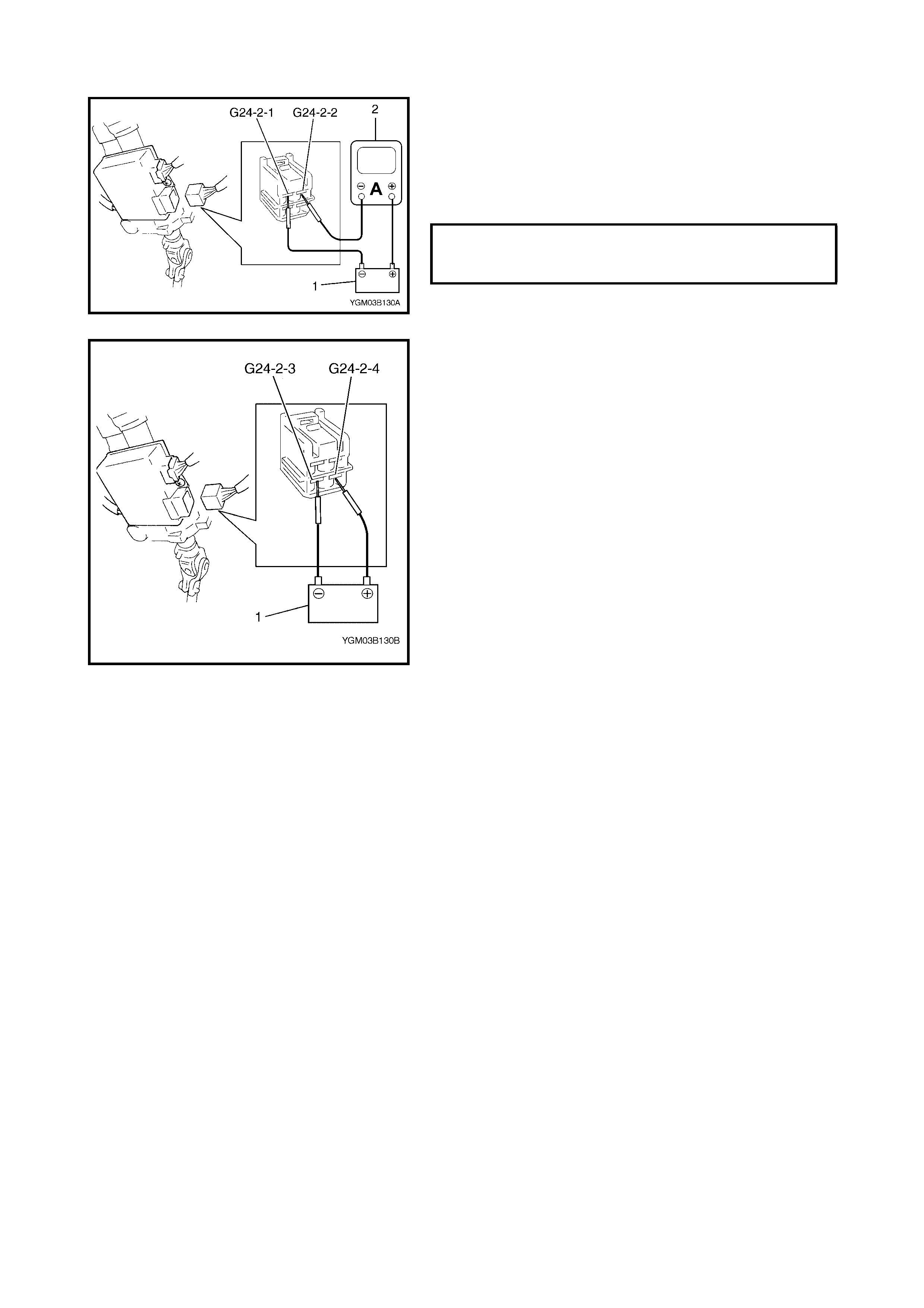
5. Connect battery (1) between G24-2-2 and G24-2-1.
Check that motor rotates smoothly, then measure
current bet ween G24-2-1 and G24-2-2 using amm eter
(2) as shown in figure .
If check result is not satisfactory, replace steering
column assembly.
6. Connect battery (1) between G24-2-4 and G24-2-3,
then check that clutch operation sound is heard.
If check result is not satisfactory, replace steering
column assembly.
STANDARD MOTOR AND CLUTCH
CIRCUIT CURRENT (REFERENCE
VALUE) 0.65 A
5. SPECIAL TO OLS
NOTE: Refer to Section 0A GENERAL INFORMATION – 7. CONSOLIDATED TOOLS for a detailed list of
special tools and the local equivalent if one is available
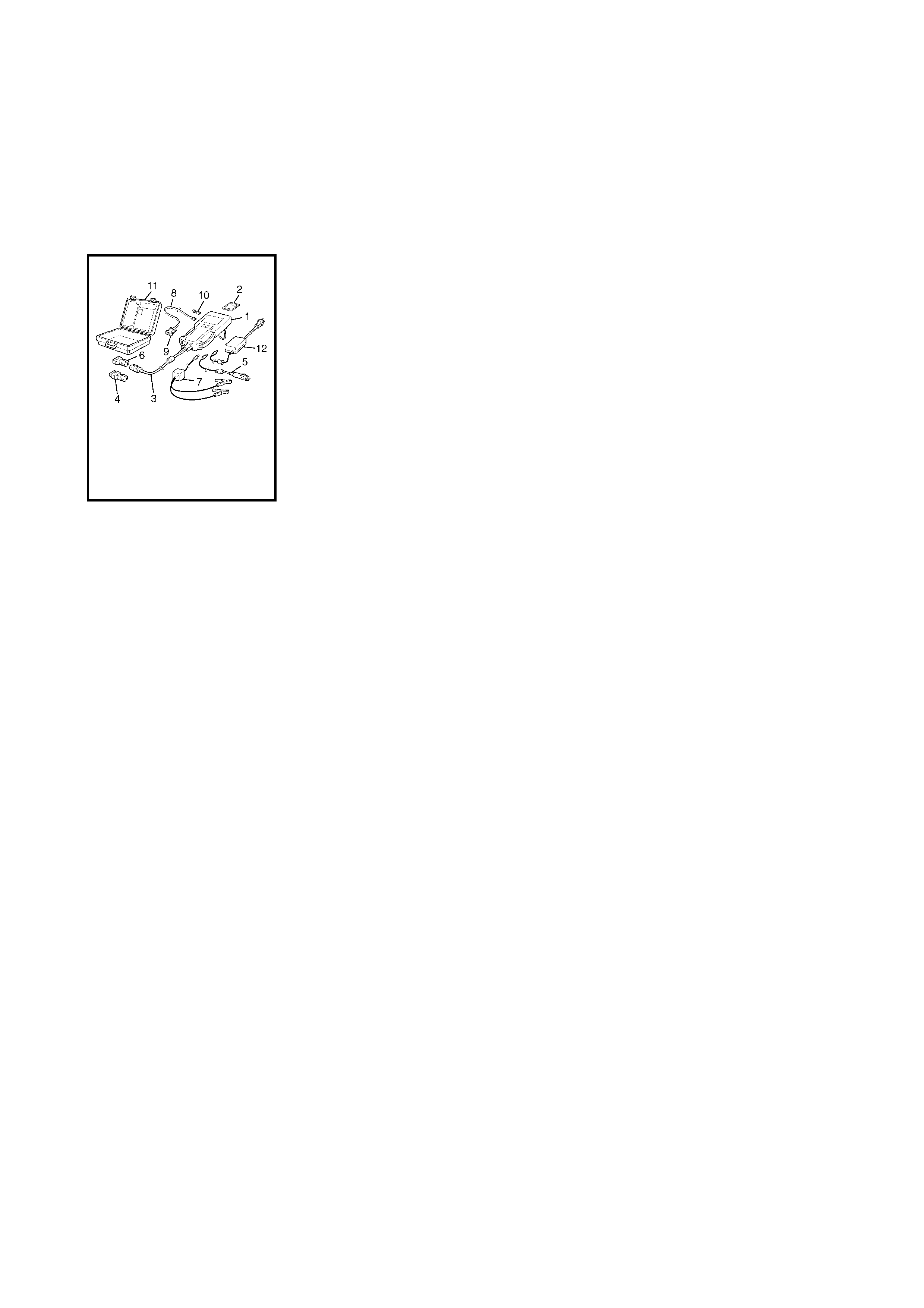
NOTE:
(A): This kit includes the following items
Tech 2 kit
See NOTE (A)
1. Tech 2 5. Cigar ett e cable 9. RS232 ada ptor
2. PCMCIA card 6. DLC loopback adaptor 10. RS232 loopback connector
3. DLC cable 7. Battery power cable 11. Storage case
4. SAE 16/19 adaptor 8. RS232 cable 12. Power supply