SECTION 3C - STEERING WHEEL
AND COLUMN
1. GENERAL DESCRIPTION
1.1 STEERING COLUMN
1.2 ST EERING WHEEL AND DRIVER
AIRBAG (INFLATOR) MODULE
2. DIAGNOSIS
2.1 INSPECTI ON AND REPAIR
REQUIRED AFTER ACCIDENT
3. O N- VEH IC L E SER VICE
3.1 SERVICE PRECAUTIONS
Service and Diagno sis
Disabling Air Bag System
Enabling Air Bag System
Handling and Storage
Disposal
3.2 DRIVER AIRBAG (INFLATOR)
MODULE
Removal
Inspection
Installation
3.3 STEERING WHEEL
Removal
Installation
3.4 CENTRING CONTACT COIL
3.5 CONTACT COIL AND COMBINATION
SWITCH ASSEMBLY
Removal
Inspection
Installation
3.6 STEERING COLUMN ASSEMBLY
Removal
Inspection
Installation
3.7 STEERING LOCK ASSEMBLY
(IGNITI ON SWITCH)
Removal
Installation
3.8 STEERING LOWER SHAFT
Removal
Installation
3.9 CHECKING STEERING COLUMN
ASSEMBLY AND LOW ER SHAFT
FOR ACCIDENT DAMAGE
Checking Procedure
4. SPECIAL TOOLS
WARNING:
For vehicles equipped with Supplemental Restraint (Airbag) System:
• Service on and around the a irbag system components or wiring must be performed only by
an au tho ris ed HO LDE N ret ail er. P leas e obs erv e all WA RNIN G S and SE RVI CE PR EC AUTI ONS
refer to Se ction 1 0B AIRBAG SYST EM, ON-VE HICLE SE RVICE befo re performing s ervice on
or around t he airbag system components or wiring. Failure to follow WARNINGS could result
in unintentional activation of the system or could render the system inoperative. Either of
these two conditions may result in severe injury.
• The procedures in this section must be followed in the order listed to temporarily disable the
airbag system an d preve nt fal se diagnost ic codes f rom setting. Failure to follow p roced ures
could result in possible airbag system activation, personal injury or otherwise unneeded air-
bag system repairs.
CAUTION:
When fastene rs are rem ov ed, always reins tall them at the same lo cation from which th ey were
removed. If a fastener needs to be replaced, use the correct part number fastener for that appli-
cation. If the correct part number fastener is not available, a fas tener of equal size and strength
(or stronger) may be used. Fasteners that are not reused, and those requiring thread-locking
compound, will be c alled o ut. T he c orre ct torque value must be u s ed w he n ins tallin g faste ne rs
that require it. If the above p rocedures are not followed, parts or system damage could result.

1. GENERAL DESCRIPTION
1.1 STEERING COLUMN
This double tube type steering column has following three important features in addition to the steering
function:
• The column is energy absorbing, designed to compress in a front-end collision.
• The ignition switch and lock are mounted conveniently on this column.
• With the column mounted lock, the ignition and steering operations can be locked to inhibit theft of the
vehicle.
To insure the energy absorbing action, it is important that only the specified screws, bolts, and nuts be used as
designated and that they are tightened to the specified torque.
When the column assembly is removed from the vehicle, special care must be taken in handling it. Use of a
steering wheel puller other than the one recommended in this manual or a sharp blow on the end of the steer-
ing shaft, leaning on the assembly, or dropping the assembly could shear the plastic shear pins which main-
tain column length and position.
1.2 STEERING WHEEL AND DRIVER AIRBAG (INFLATOR) MODULE
• The driver airbag (inflator) module is one of the supplemental restraint (airbag) system components and is
mounted to the centre of the steering wheel. During certain front end crashes, the airbag system supple-
ments the restraint of the driver’s and passenger’s seat belts by deploying the airbags.
• The airbag (inflator) module should be handled with care to prevent accidental deployment. When servic-
ing, be sure to observe all WARNINGS and CAUTIONS and SERVICE PRECAUTIONS, refer to
Section 10B, 3 ON-VEHICLE SERVICE.
2. DIAGNOSIS
For maintenance service of the steering wheel and column, refer to Section 0B GENERAL INFORMATION.
For diagnosis of the steering wheel and column, refer to Section 3 STEERING, SUSPENSION, WHEELS
AND TYRES.
For diagnosis of the airbag system, refer to Section 10B AIRBAG SYSTEM.
2.1 INSPECTION AND REPAIR REQUIRED AFTER ACCIDENT
After an accident, w hether the a irbag has been d eployed or no t, be sure to perfor m che cks, inspect ions and
repairs, refer to 3.9 CHECKING STEERING COLUMN ASSEMBLY AND LOWER SHAFT FOR ACCIDENT
DAMAGE in this Section, also refer to Section 10B, 3.2 REPAIRS AND INSPECTIONS REQUIRED AFTER A
COLLISION
3. ON-VEHICLE SERVICE
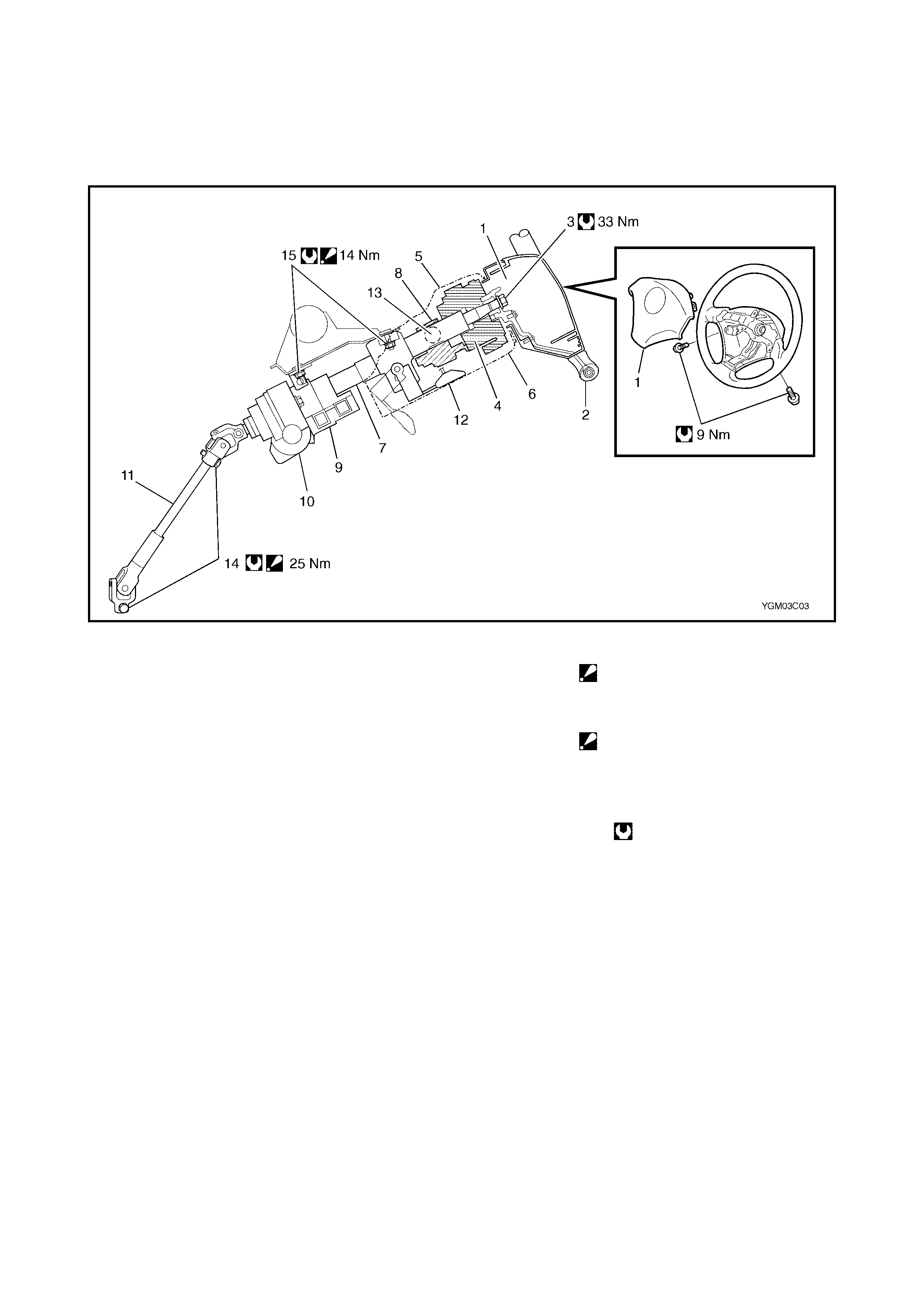
Legend
3.1 SERVICE PRECAUTIONS
For service precautions, refer to Section 10B, 3.1 SERVICE PRECAUTIONS under 3. ON-VEHICLE
SERVICE. SERVICE AND DIAGNOSIS
For diagnosis and servicing, refer to Section 10B, 3.1 SERVICE PRECAUTIONS under 3. ON-VEHICLE
SERVICE. DIS ABLING AIRB AG SYSTEM
For disabling airbag system, refer to DISABLING AIRBAG SYSTEM in Section 10B, 3.1 SERVICE
PRECAUTIONS.ENABLING AIRBAG SYSTEM
For enabling airbag system, refer to ENABLING AIRBAG SYSTEM in Section 10B, 3.1 SERVICE
PRECAUTIONS.HANDLING AND STORAG E
For handling and storage, refer to HANDLING AND STORAGE in Section 10B, 3.1 SERVICE
PRECAUTIONS.DISPOSAL
For disposal, refer to HANDLING AND STORAGE in Section 10B, 3.1 SERVICE PRECAUTIONS.
1. Dr iver ai rb ag (inflator) module 9. P/S control mod ule
(if equipped) 14. Upper and lower joint bolt
: A ft e r ti gh te ning l owe r jo int
bolt, tighten upper joint bolt.
2. Steering wheel
3. Steering wheel n ut 10. Motor for P/S system
4. Contact coil & combination
switch assembly (if equipped) 15. Steering column
mounting nut
: A ft e r ti gh te ning l owe r nu t,
tighten upper nut.
11. Steeri ng lower shaft
5. Steering column upper cover 12. Tilt le ver
6. Steering column lower cover 13. Immobiliser control module
(if equipped)
7. Steering column assembl y Tightening torque
8. Steer ing loc k a s sembl y
(ignition switch)
3.2 DRIVER AIRBAG (INFLATOR) MODULE
WARNING: When handling an airbag (inflator) module, be sure to read Section 10B, 3.1 SERVICE
PRECAUTIONS and observe each instruction. Failure to follow them could cause a damage to the
airbag (inflator) module or result in personal injury.
REMOVAL
1. Disconnect negative cable at battery.
2. Disable airbag system. Refer to DISABLING AIRBAG
SYSTEM in Section 10B, 3.1 SERVICE
PRECAUTIONS.
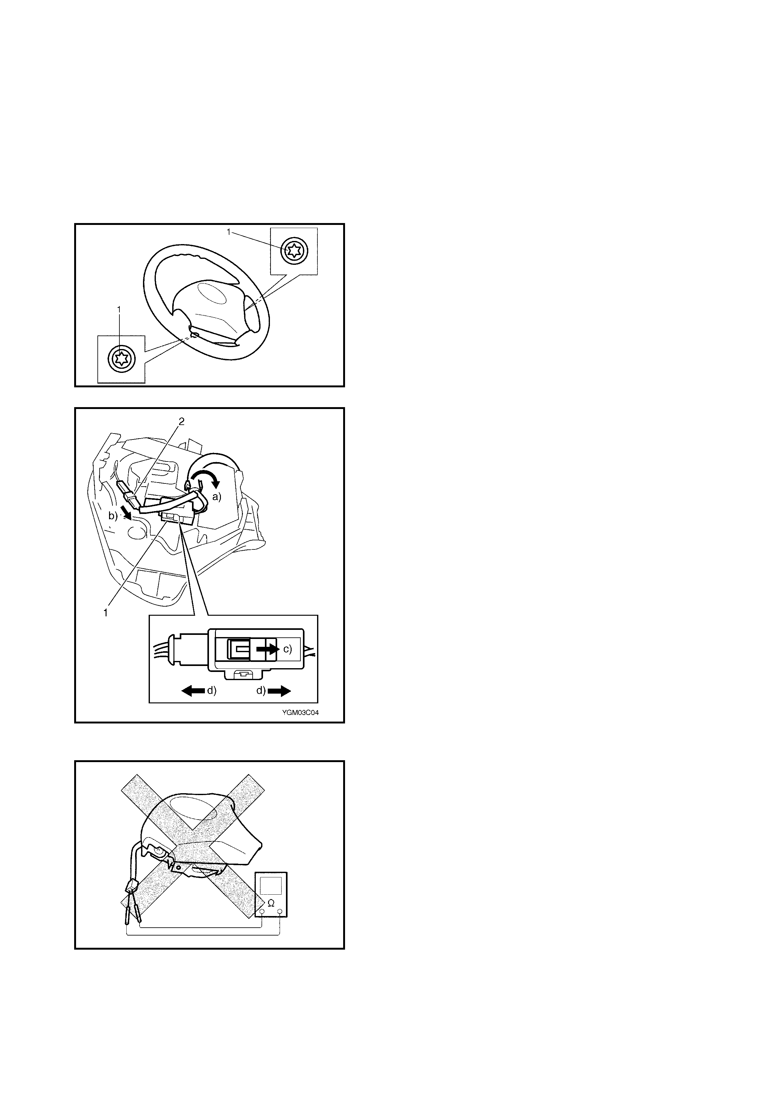
3. Loosen 2 mounting bolts (1) on both sides of driver
airbag (inflator) module.
4. Remove driver airbag (inflator) module (3) from
steeri ng wheel.
5. Disconnect yellow connector (1) of driver airbag (infla-
tor) module and horn connector (2) in order a) – d)
shown in figure.
INSPECTION
WARNING: Never disassemble driver airbag (infla-
tor) module or measure its resistance. Otherwise,
personal injury may result.
CAUTION: If airbag (inflator) module was dropped
from a height of 90 cm or more, it should be
replaced.
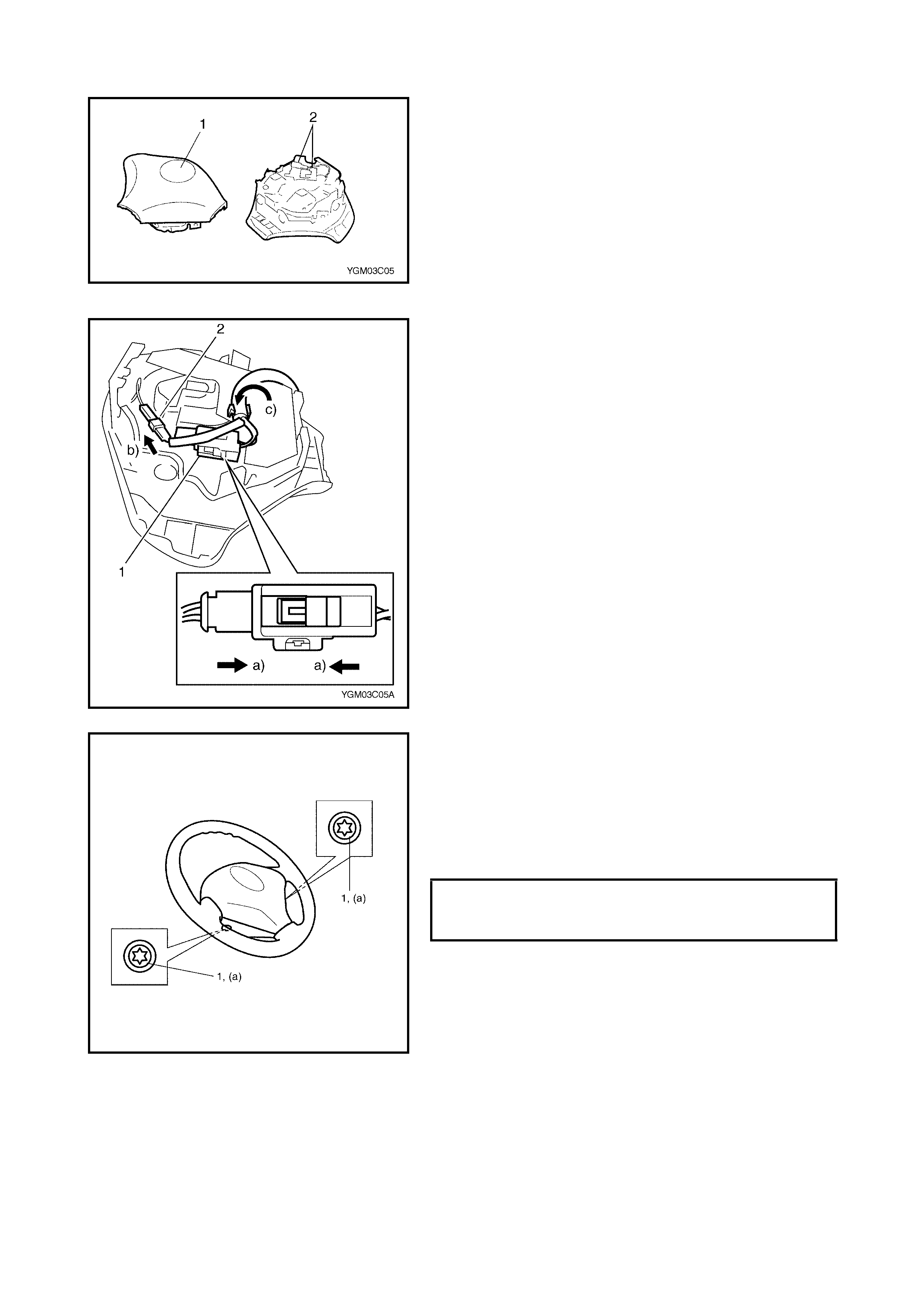
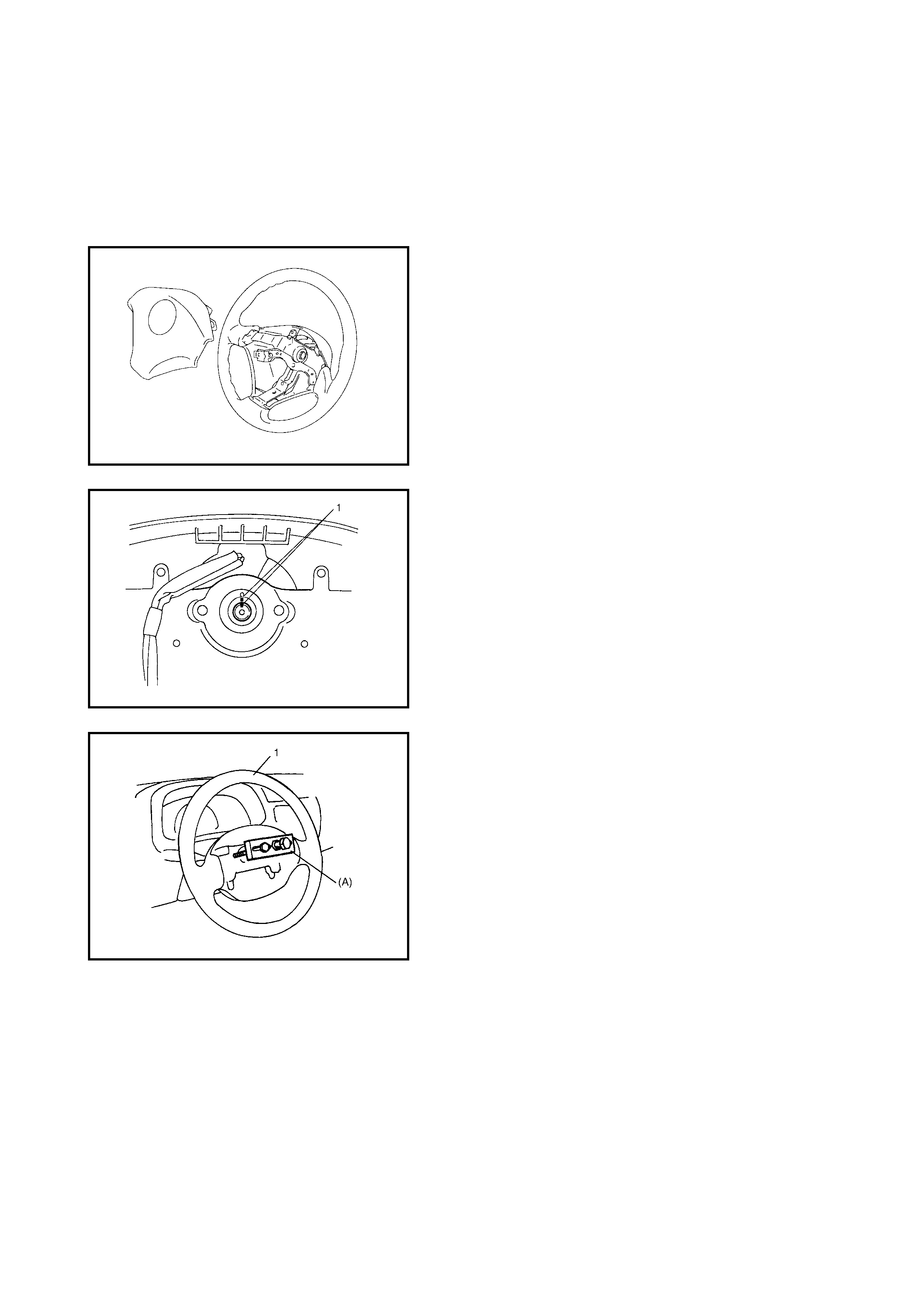
Check airbag (inflator) module visually and if any of the fol-
lowing is found, replace it with a new one.
• Airbag being deployed
• Trim cover (pad surface) (1) is cracked
• Wire harness or connector (2) is damaged
• Airbag (inflator) module is damaged or has been
exposed to strong impact (dropped).
INSTALLATION
1. Check that horn wire is connected to horn connector
(2) securely.
2. Connect yellow connector (1) of driver airbag (inflator)
module (3) and horn connector securely in order a) – c)
as shown in figure.
3. Install the driver airbag (inflator) module to the steering
wheel, taking care that no part of the wiring harness is
caught between them.
4. Make sure that the clearance between the module and
the steering wheel is uniform in all places.
5. Tighten driver airbag (inflator) module mounting bolts
(1) to specified torque.
6. Connect negative cable at battery.
7. Enable airbag system. Refer to ENABLING AIRBAG
SYSTEM in Section 10B, 3.1 SERVICE
PRECAUTIONS.
DRIVER AIRBAG (INFLATOR) MOD-
ULE MOUNTING BOLT (a)
TORQUE SPECIFICATION 9 Nm
3.3 STEERING WHEEL
CAUTION: Removal of the steering wheel allows the contact coil to turn freely but do not turn the
contact coil (on the combination switch) more than allowable number of turns (about two and a
half turns from the centre position clockwise or counterclockwise respectively), or coil will break.
REMOVAL
1. Remove driver airbag (inflator) module from steering
wheel. Refer to 3.2 DRIVER AIRBAG (INFLATOR)
MODULE in this Section.
2. Remov e steering shaft nut.
3. Make align men t mar k s (1) on st eeri ng wheel and sh aft
for a guide during reinstallation.
CAUTION: Do n ot hammer the e nd of the shaft. Ham-
mering it will loosen the plastic shear pins which main-
tain the column length and impair the collapsible
design of the column.
4. Remove steering wheel (1) with special tool (A) 09944-
36011.
INSTALLATION
1. Check that the vehicle’s front tyres are in the straight-
ahead position and the contact coil is centred. Refer to
3.4 CENTRING CONTACT COIL in this Section.
CAUTION: These two conditions are a prerequisite
for installation of the steering wheel. If the steering
wheel has been installed without these conditions
being met, the contact coil will break when the steer-
ing wheel is turned.
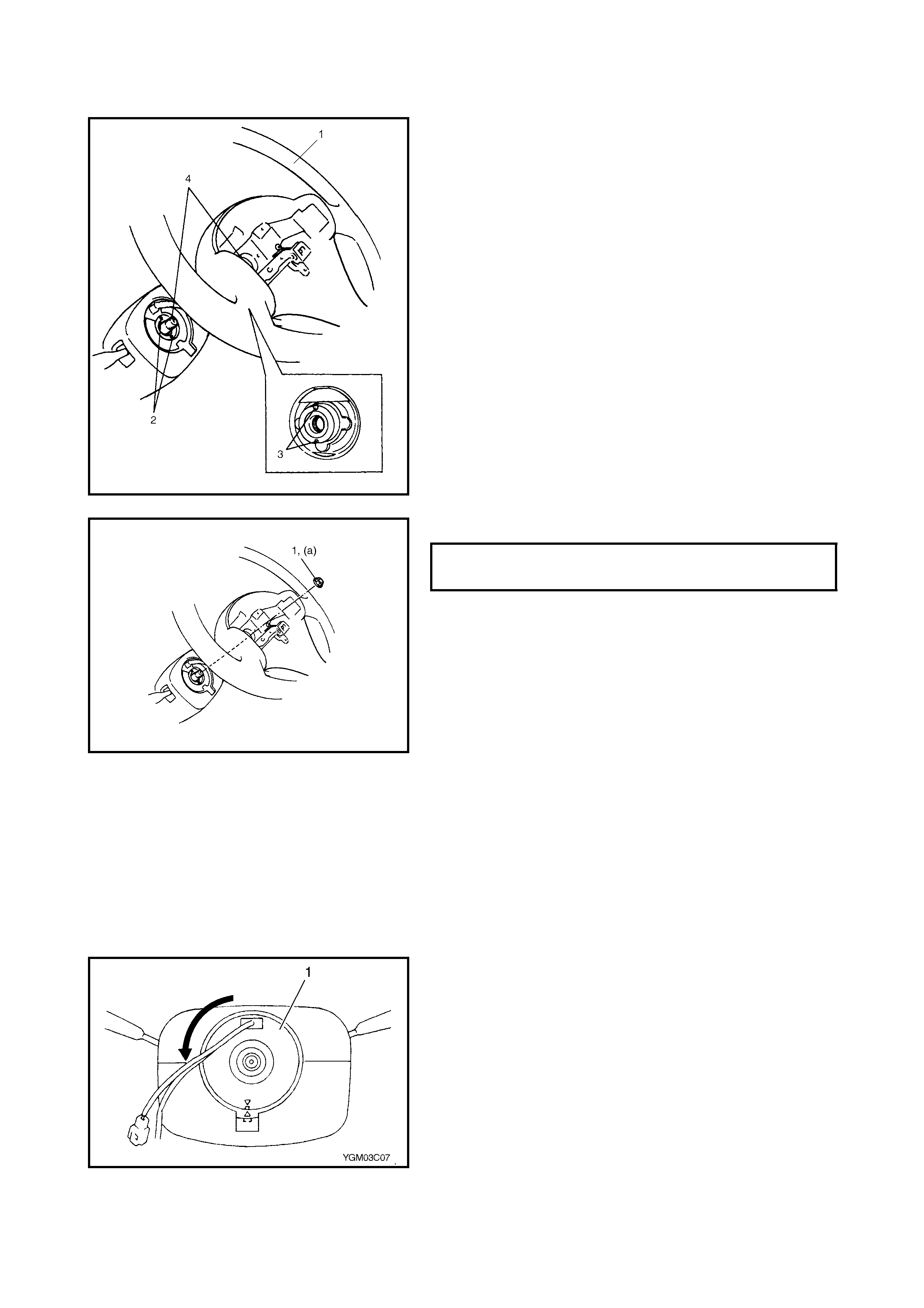
2. Install steering wheel (1) to steering shaft with 2 lugs
(2) on contact the coil fitted in two grooves (3) in the
back of the steering wheel and also aligning marks (4)
on the steering wheel and steering shaft.
3. Tighten steering shaft nut (1) to specified torque.
4. Install driver airbag (inflator) module to steering wheel.
Refer to 3.2 DRIVER AIRBAG (INFLATOR) MODULE
in this Section.
3.4 CENT RING CONTACT COIL
1. Check that vehicle’s wheels (front tyres) are set in the
straight-ahead pos ition.
2. Check that ignition switch is in “LOCK” position.
3. Turn contact coil counterclockwise slowly with a light
force until contact coil will not turn any further.
NOTE: Contact coil can turn a maximum o f about 5 turns,
that is, if it is in the centre position, it can turn about two
and a half tur ns both clockwise and count erclockwise.
STEERING SHAFT NUT (a)
TORQUE SPECIFICATION 33 Nm
4. From the position where the contact coil was unable to
turn any further (it stopped), turn it back clockwise
about two and a half rotations and align centre (1) with
alignment mark.
3.5 CONTACT COIL AND COMBINATION SWITCH ASSEMBLY
CAUTION: Do not turn contact coil (on combination switch) more than the allowable number of
turns (about two and a half turns from the centre position clockwise or counterclockwise respec-
tively), or coil will break.
REMOVAL
1. Remove the steering wheel from the steering column,
refer to 3.3 STEERING WHEEL in this Section.
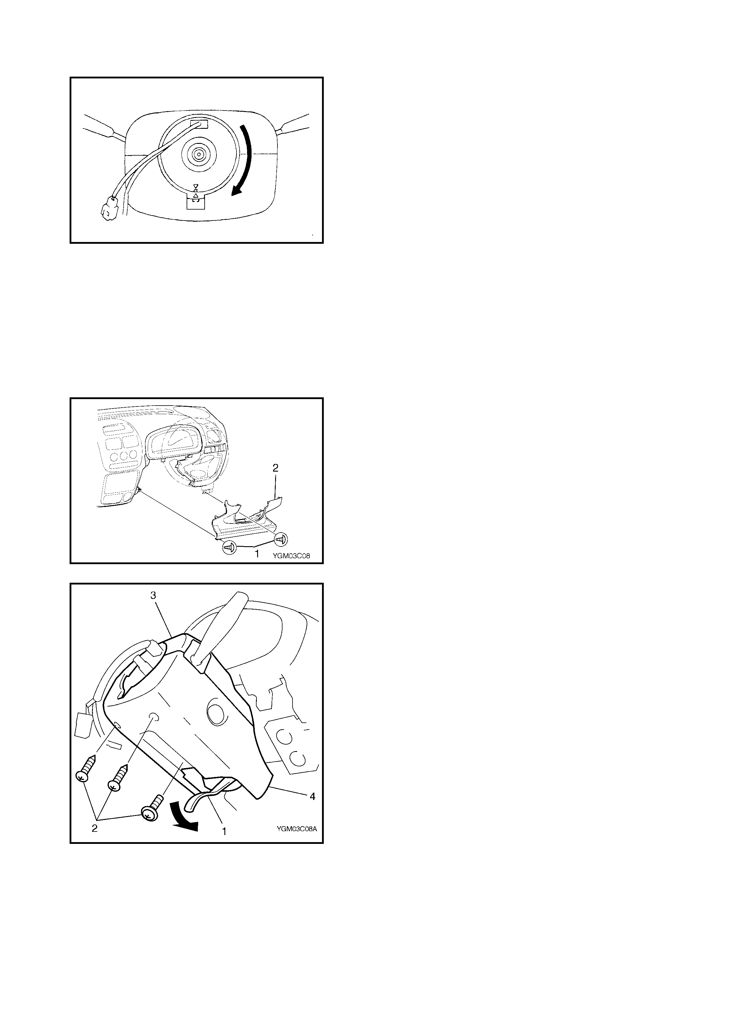
2. Remov e steering column hole cover (1).
3. Pull down tilt lever (1), then remove the steering
column cover screws (2).
4. Separate upper cover (3) and lower cover (4), and
remove them.
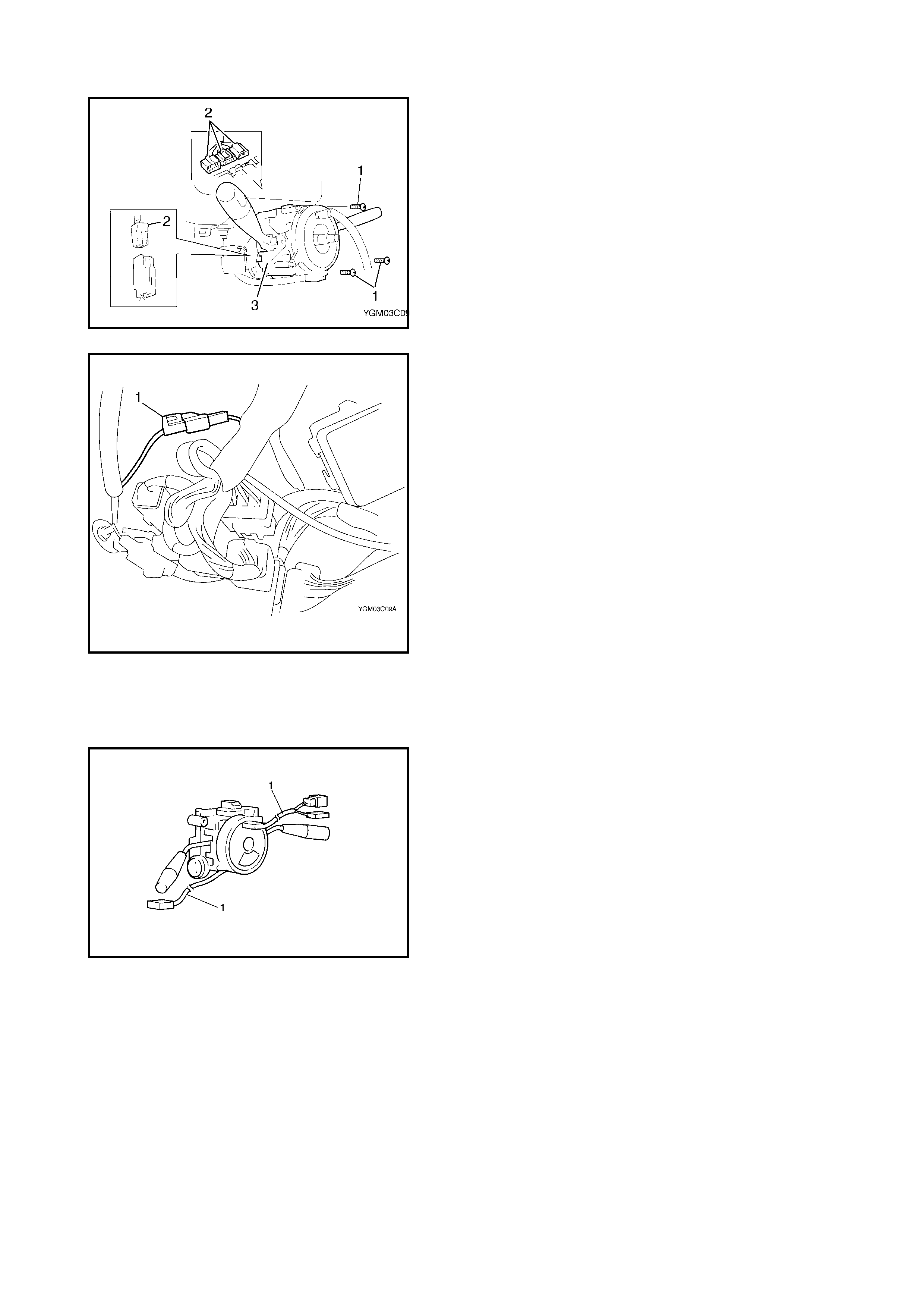
5. Remove the contact coil and combination switch
assembly screws (1) and disconnect connectors (2)
from combination switch (3).
6. Disconnect horn connector (1) from instrument panel
harness.
7. Remove c ont act coil a nd combi nation switch ass em bly
from steering column.
INSPECTION
Check contact coil harness (1) for any signs of scorching,
melting or other damage.
If it is damaged, replace it.
INSTALLATION
1. Check to make sure that the vehicle’s front tyres are
set in the straight-ahead position and the ignition
switch is in th e “LOC K ” pos it io n.
2. Connect all connectors disconnected in REMOVAL.
3. Install contact coil and combination switch assembly
(3) to steering column.
NOTE: New contact coil and combination switch assembly
is supplied with contact coil set and held at its centre posi-
tion with a lock pin (1) and seal (2). Remove this lock pin
after installing contact coil and combination switch assem-
bly to steering column.
4. Install steering column upper cover (2) and lower cover
(3), and then tighten steering column cover screws (1).
CAUTION: When installing lower cover (3) and
upper cover (2), take care that the contact coil and
combination switch lead wire is not caught between
covers.
5. Install steering column hole cover (1).
6. Install steering wheel to steering column. Refer to
3.3 STEERING WHEEL in this Section.
3.6 STEERING COLUMN ASSEMBLY
CAUTION: Once the steering column is removed from the vehicle, the column is extremely suscepti-
ble to damage.
• Dropping the column assembly on its end could collapse the steering shaft or loosen the plastic
shear pins which maintain column length.
• Leaning on the column assembly could cause it to bend or deform.
Any of the above damage could impair the column’s collapsible design.
NOTE: When servicing the steering column or any column-mounted component, remove the steering wheel.
But when removing the steering column simply to gain access to instrument panel components, leave the
steering wheel installed on the steering column. REMOVAL
WARNING: Never rest a steering column assembly on the steering wheel with the airbag (infla-
tor) module face down and column vertical. Otherwise, personal injury may result.
1. Disconnect negative cable at battery.
2. Disable airbag system. Refer to DISABLING AIRBAG SYSTEM in Section 10B, 3.1 SERVICE
PRECAUTIONS.
3. If it is nec essary to remove the steeri ng wheel and c ontac t coil and comb ination switch assembly, refer to
3.3 STEERING WHEEL and 3.5 CONTACT COIL AND COMBINATION SWITCH ASSEMBLY in this
Section.
If it is not necessary to remove the steering wheel and contact coil and combination switch assembly,
perform the following procedure.
a. Turn steer ing wheel so that vehicle’s fron t tyres are at straight-ahead position .
b. Turn ignition switch to “LOCK” position and remove key.
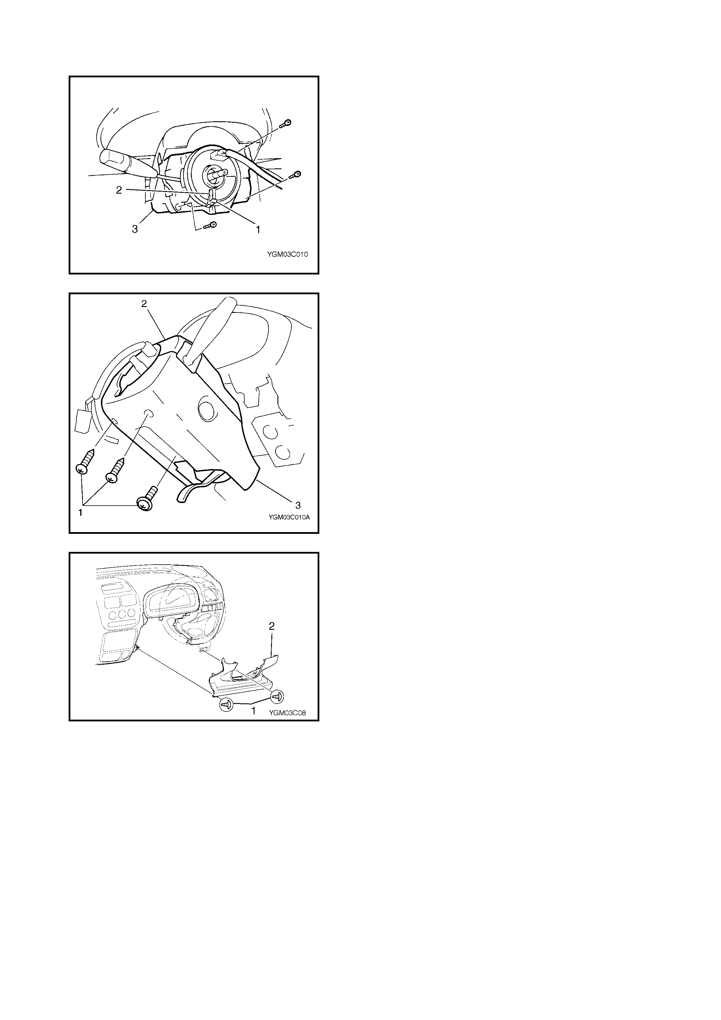
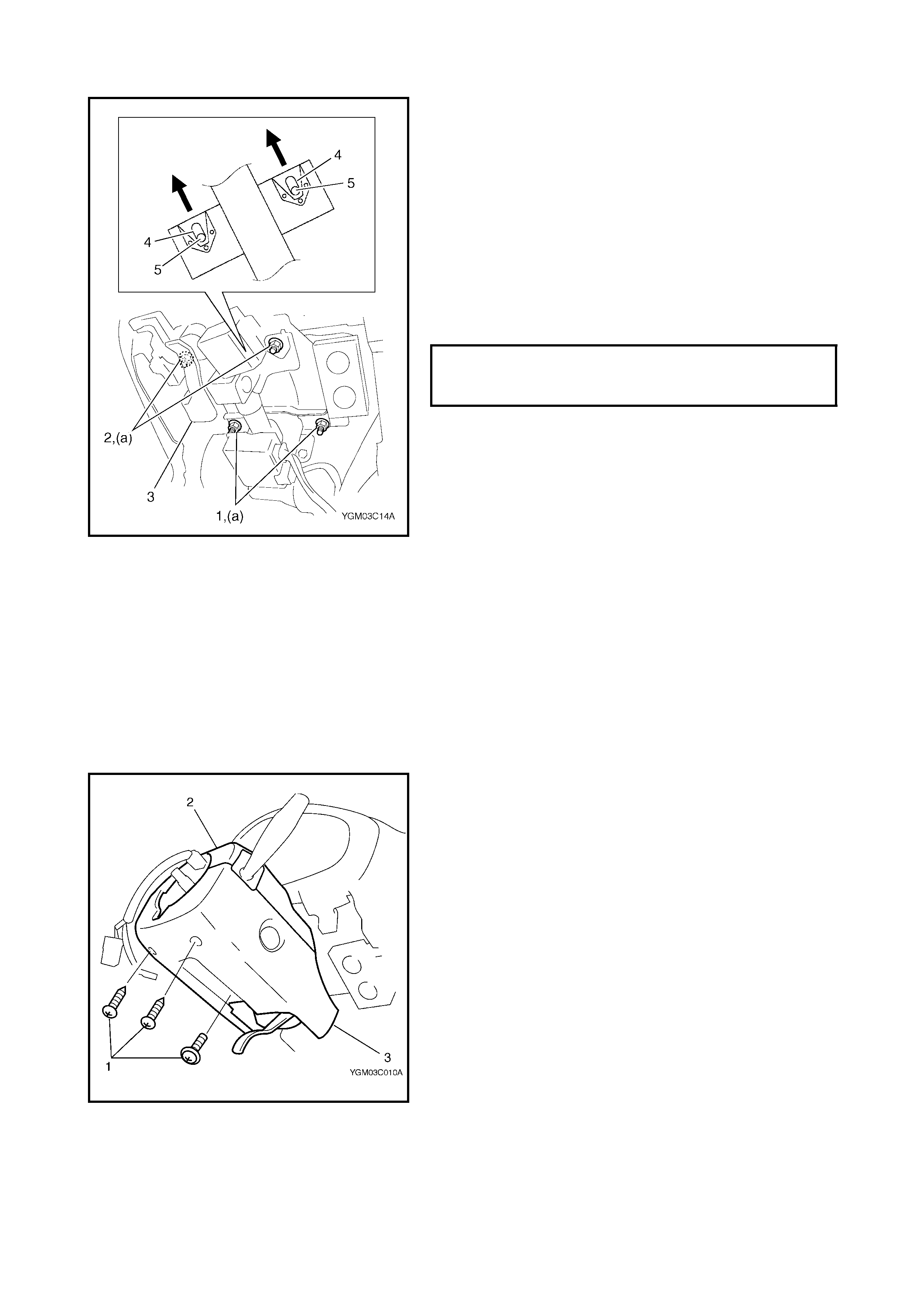
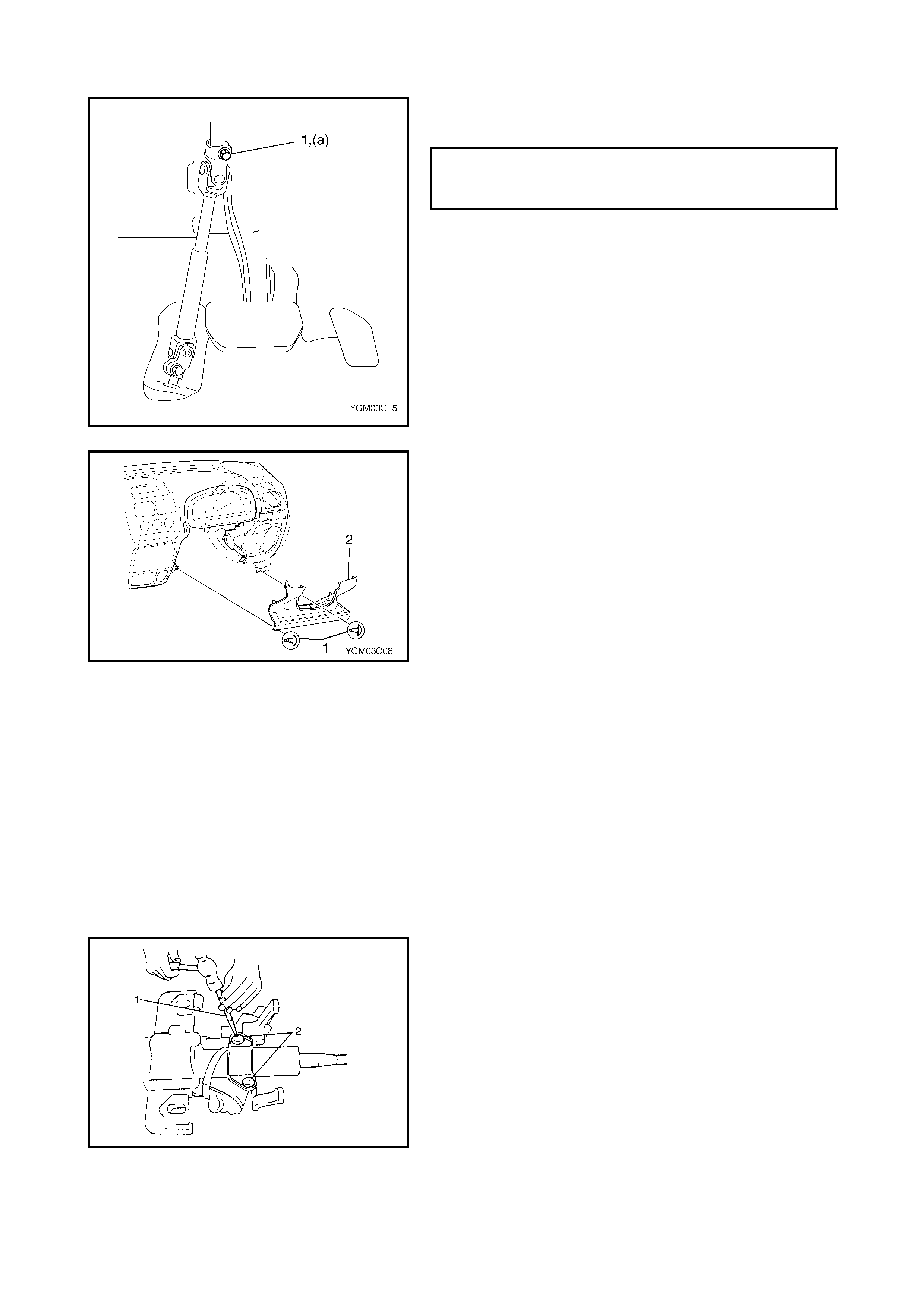
4. Remove steering column hole cover screws (1) and
remove steering col umn hole cover by unclipping in six
places.
5. Pull down lilt lever (1) and then remove steering
column cover screws (2).
6. Separate upper column cover (3) and lower column
cover (4), then remove them .
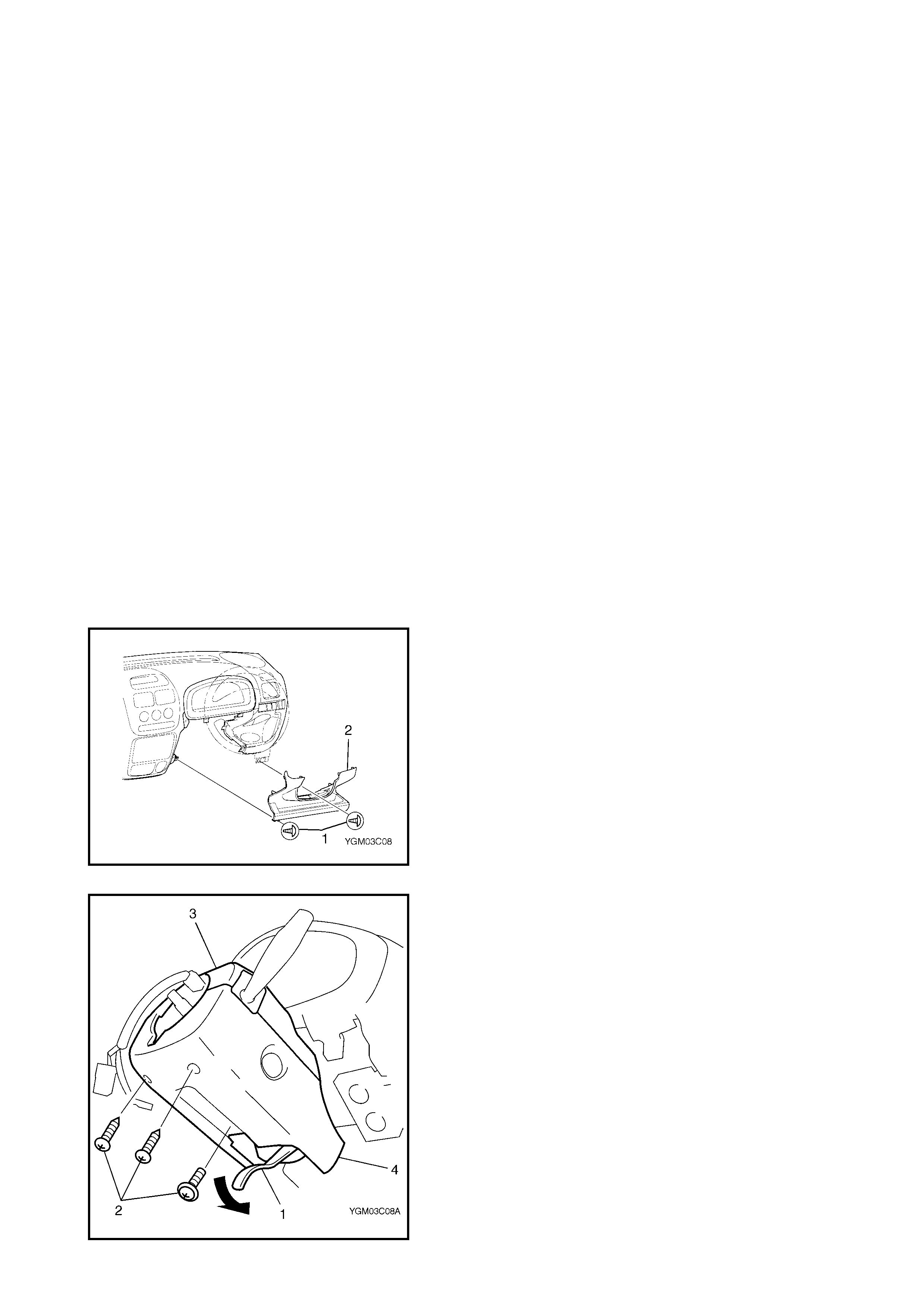
7. Disconnect connectors (1) from combination switch
assembly (2).
8. Disconnect ignition switch connectors (1) from ignition
switch (2).
9 . Dis c on nec t im mob ilis e r c o ntro l mod ule conn ec tor (1)
(if equipped).
10. Disconnect horn connector (1) from instrument panel
harness.
11. If equipped with power steering (P/S) system, discon-
nect connector (2) from P/S control module (1).
12. Remove steering joint cover.
13. Make alignment marks (1) on joint (2) of steering lower
shaft (3) and steering column for a guide during rein-
stallation.
14. Remove joint bolt (steering column side) (4).
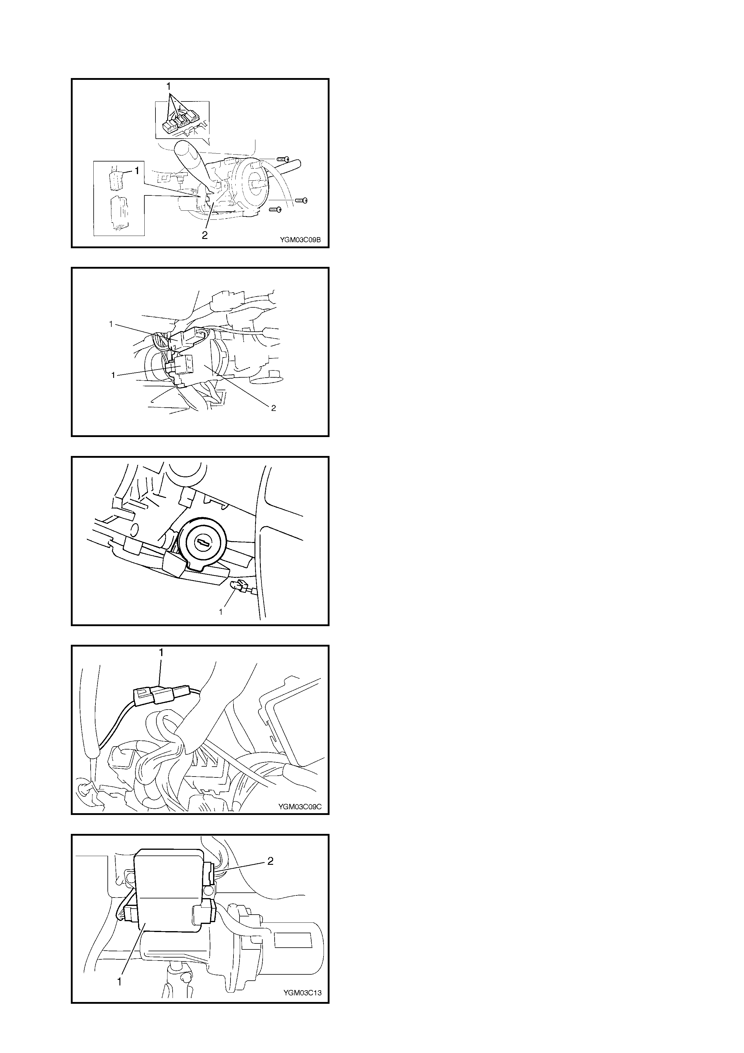
15. Pull up tilt lever to lock steering column.
NOTE: Do not release tilt lever lock with steering column
removed from vehicle, otherwise steering column base
position must be adjusted at installion.
16. Remove steering column mounting nuts (A, B).
17. Remove steering column assembly from vehicle.
CAUTION: Do not separate steering column assem-
bly into steering column and shaft. If column or
shaft is defective, replace it as an assembly.
18. If it is necessary to remove the steering lock assembly
(ignition switch), refer to 3.7 STEERING LOCK
ASSEMBLY (IGNITION SWITCH) in this Section.
INSPECTION
NOTE: Vehicles involved in accidents resulting in body damage, where the steering column has been
impacted (or airbag deployed), may have a damaged or misaligned steering column. For the checking proce-
dure of the steering column assembly, refer to 3.9 CHECKING STEERING COLUMN ASSEMBLY AND
LOWER SHAFT FOR ACCIDENT DAMAGE in this Section.
INSTALLATION
CAUTION: Steering column mounting nuts should be tightened first, followed by shaft joint bolts.
The wrong tightening order could cause damage to shaft joint.
1. Be sure that front wheels and steer ing wheel are in the
straight ahead position.
If steering lock assembly (ignition switch) is removed,
install it, refer to 3.7 STEERING LOCK ASSEMBLY
(IGNITION SWITCH) in this Section.
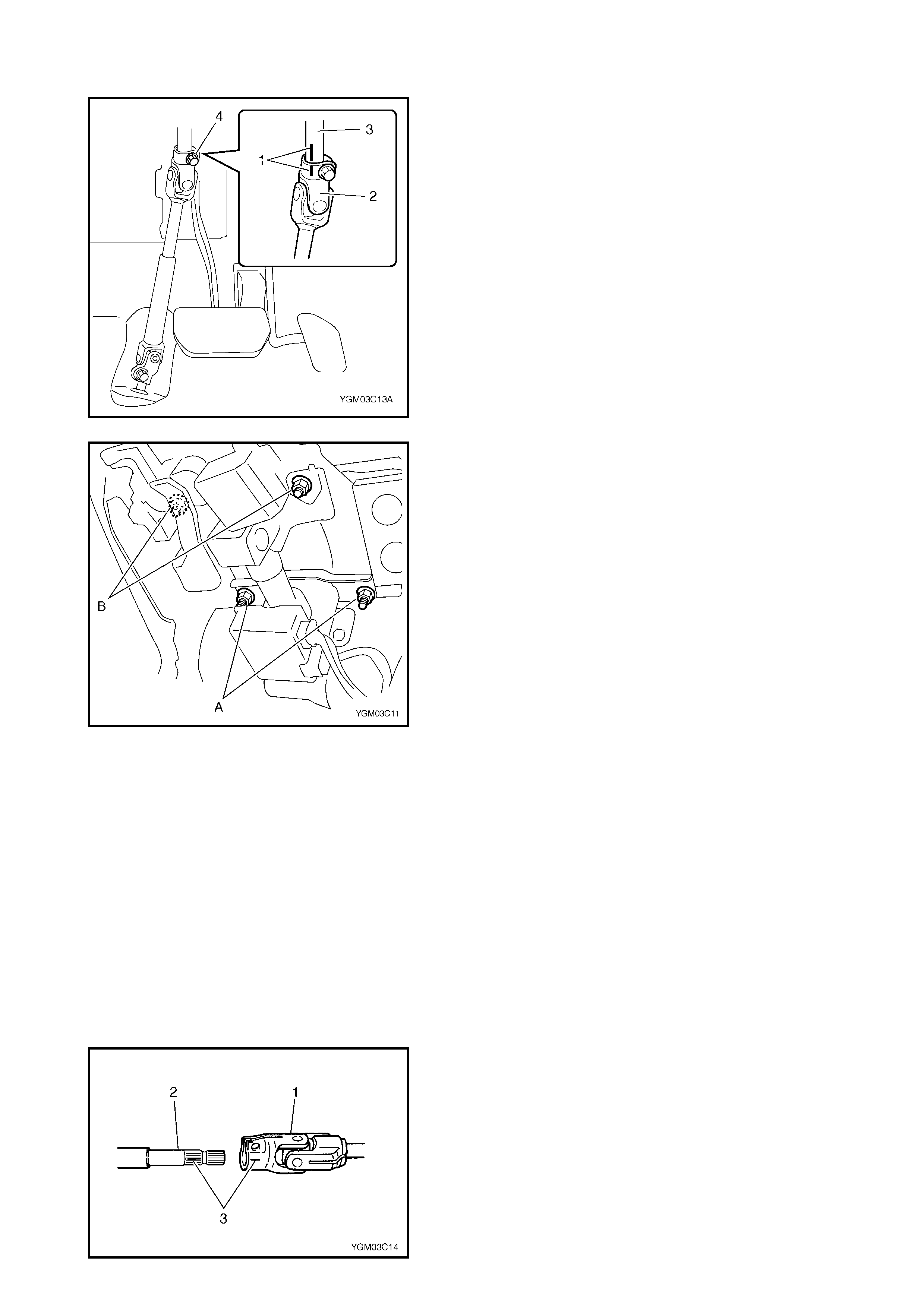
2. Install steering lower shaft joint (1) to steering column
shaft (2) aligning matching marks (3) made before
removal.
3. Install steering column and tighten steering column
lower and upper mounting nuts (1,2) temporarily at this
step.
4. If tilt lever lock is released, adjust steering column base
position as follows:-
a. Be sure to release tilt lever (3).
b. Fit steering column upper bracket slot ends (4) to
steering column hanger upper stud bolts (5).
c. Fix steering column by pulling up tilt lever (3).
5. Tighten steering column lower and upper mounting
nuts (1,2) to specified torque in the order (1)-(2)
indicated in the figure.
6. Connect all connectors disconnected in REMOVAL.
• Ignition switch
• Combination switch
• P/S control module (if equipped)
• Horn
• Immobiliser control module (if equipped)
7. If contact coil and combination switch assembly is
removed, install it.
Refer to 3.5 CONTACT COIL AND COMBINATION
SWITCH ASSEMBLY in this Section.
8. Install upper and lower column covers (2,3) to steering
column assembly with screws (1).
STEERING COLUMN UPPER AND
LO WER MOUNTING NUTS (a)
TORQUE SPECIFICATIONS 25 Nm
9. Tighten joint bolt (1) (steering column side) to specified
torque.
10. Install steering joint cover.
11. Install steering column hole cover (1).
12. If steering wheel is removed, install steering wheel.
Refer to 3.3 STEERING WHEEL in this Section.
13. Enable airbag system. Refer to ENABLING AIRBAG
SYSTEM in Section 10B, 3.1 SERVICE
PRECAUTIONS.
14. Connect negative battery cable.
3.7 STEERING LOCK ASSEMBLY (IGNITION SWITCH)
REMOVAL
1. Remove steering column. Refer to 3.6 STEERING
COLUMN ASSEMBLY in this Section.
2. Using centre punch (1), loosen and remove steering
lock mounting bolts (2).
NOTE: Use ca re not to da mage a luminum p ar t of stee r-
ing lock body with centre punch.
3. Turn ignition key to “ACC” or “ON” position and remove
steeri ng lock assem bly fro m steering column.
STEERING SHAFT JOINT BOLT
(STEERING COLUMN SIDE) (a)
TORQUE SPECIFICATION 25 Nm
INSTALLATION
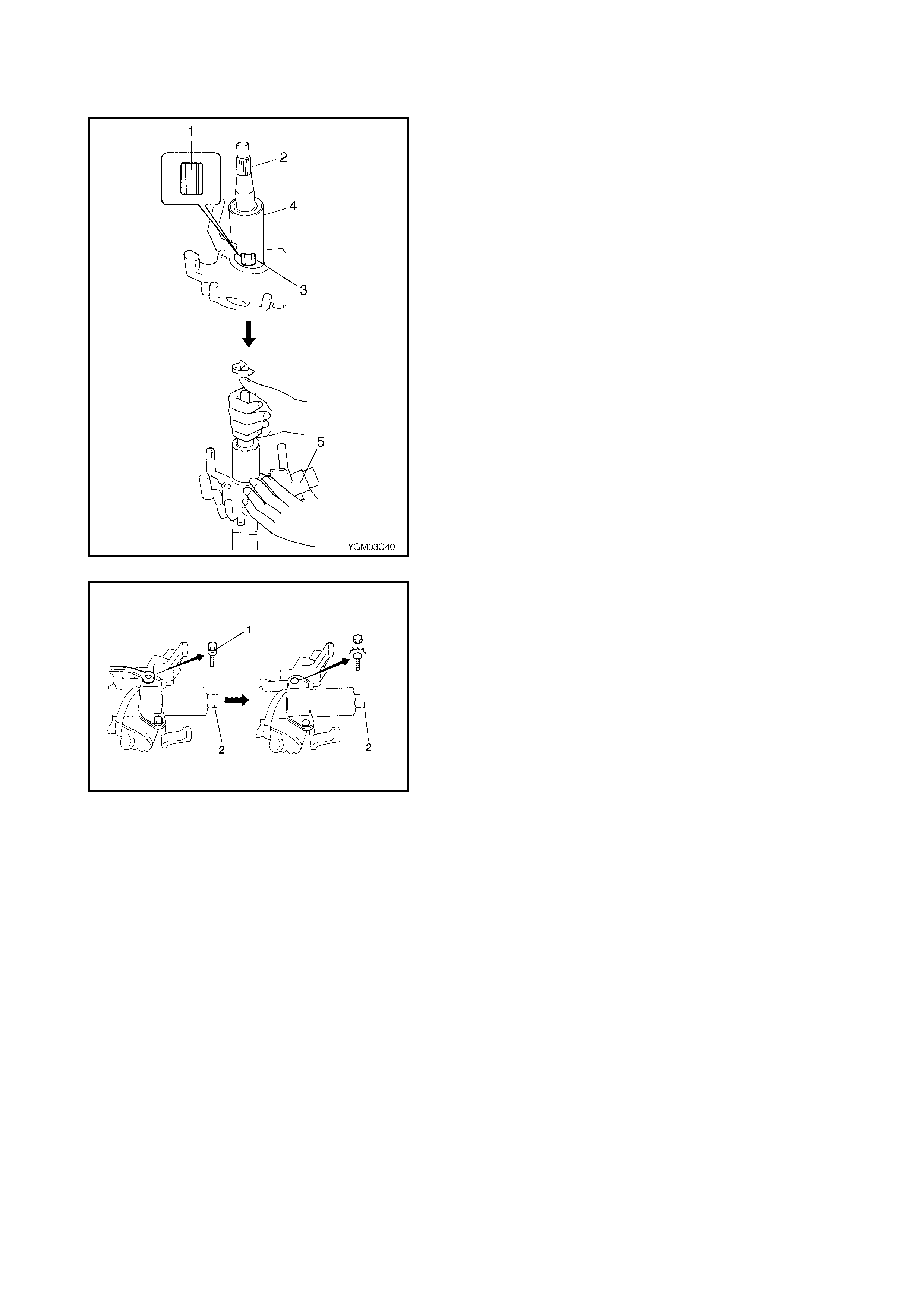
1. Position oblong hole (1) of steering shaft (2) in the
centre of hole (3) in column (4).
2. Turn ignition key to “ACC” or “ON” position and install
steering lock assembly (5) onto column (4).
3. Now turn ignition key to “LOCK” position and pull it out.
4. Align hub on lock with oblong hole (1) of steering shaft
(2) and rotate shaft to assure that steering shaft (2) is
locked.
5. Tighten new bolts (1) until the head of each bolt has
broken off.
6. Turn ignition key to “ACC” or “ON” position and ensure
that steering shaft (2) rotates smoothly. Also check the
lock operation.
7. Install steering column. Refer to 3.6 STEERING
COLUMN ASSEMBLY in this Section.
3.8 STEERING LOWER SHAFT
CAUTION: Never turn steering wheel while steering lower shaft is removed.
If it has been turned and contac t coil (on com bination switch) has moved from its centred position, it
will need to be recentred. Also, turning steering wheel more than about two and a half turns will break
contact coil .
REMOVAL
1. Turn steering wheel so that vehicle’s front tyres are at
the straight-ahead position .
2. Turn ignition switc h to “LOCK” position and remove key.
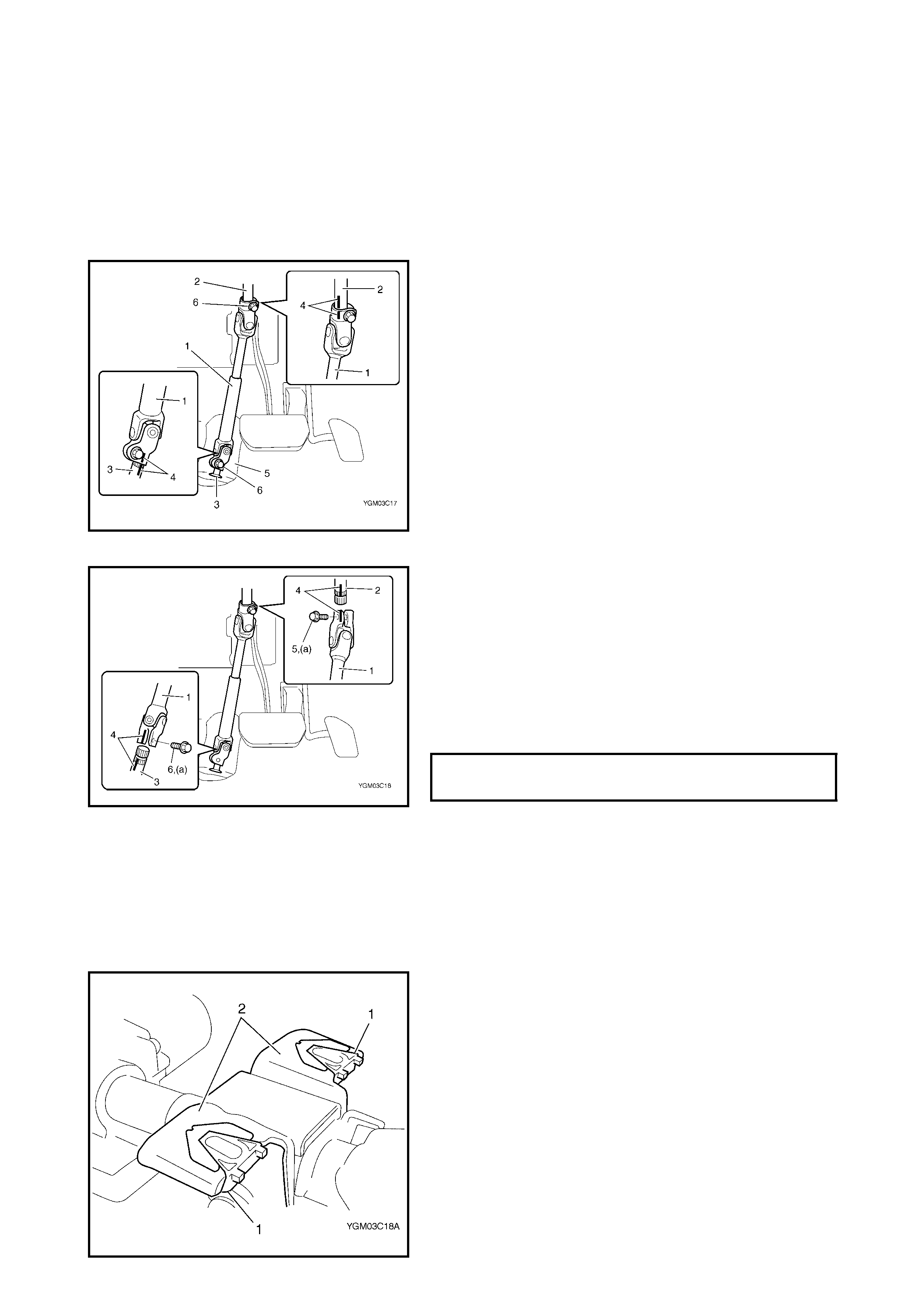
3. Remov e steering joint cover (5).
4. Make alignment marks (4) on lower shaft (1) and
steering column shaft (2) and l ower shaft (1) and pinion
shaft (3) for a guide duri ng reinstallation.
5 . R e mo ve low e r sh a ft jo in t b o lts (6).
6. Remov e steering lower shaft (1).
INSTALLATION
1. Be sure that front wheels and steer ing wheel are in the
straight ahead position.
2. Insert lower shaft (1) into steering column shaft and
align mark s made dur ing rem oval (4).
3. Insert lower shaft (1) into pinion shaft (3) and align
marks made during removal (4).
4. Tighten joint bolt (pinion shaft side) (6) to specified
torque first and then joint bolt (steering column side)
(5) to specified torque.
5. Install steer ing joint cover.
3.9 CHECKING STEERING COLUMN ASSEMBLY AND
LOWER SHAFT FOR ACCIDENT DAMAGE
NOTE: Vehicles involved in accidents resulting in body damage, where steering column has been
impacted (or airbag deployed) may have a damaged or misaligned steering column.
CHECKING PROCEDURE
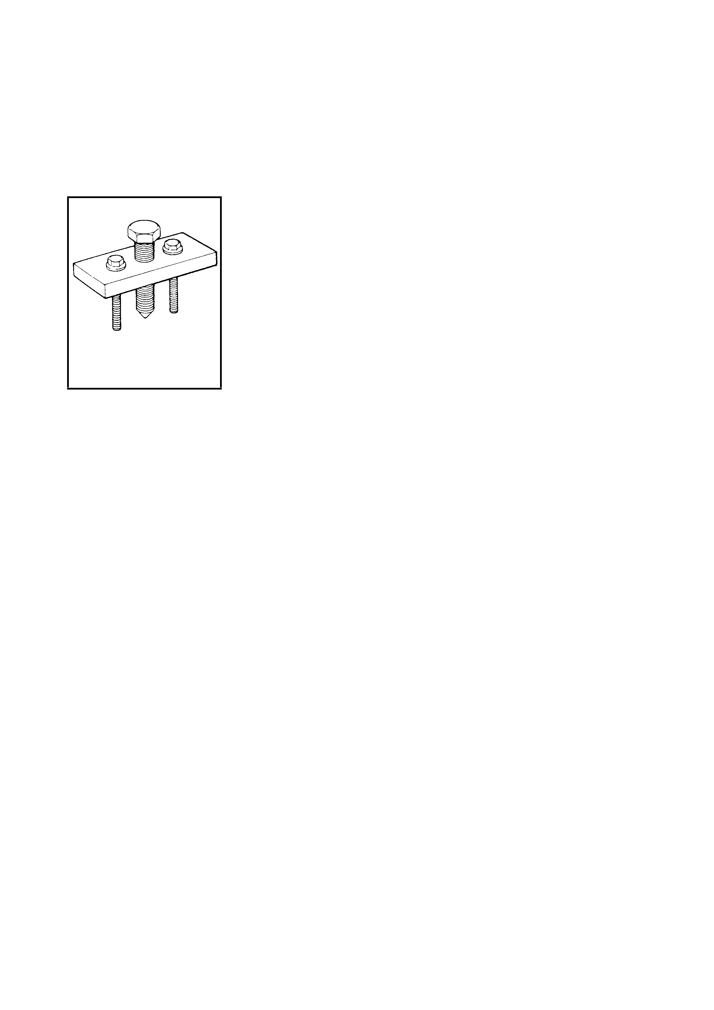
1. Check that each caps ule (1) is attached to the st eeri ng
column bracket (2) securely.
If capsules are loose, replace steering column
assembly.
2. Check the two capsules for damage for signs of
cracking or breakage.
If any faults are found, replace the whole steering
column assembly.
STEERING SHAFT JOUNT BOLT (a)
TORQUE SPECIFICATION 25 Nm
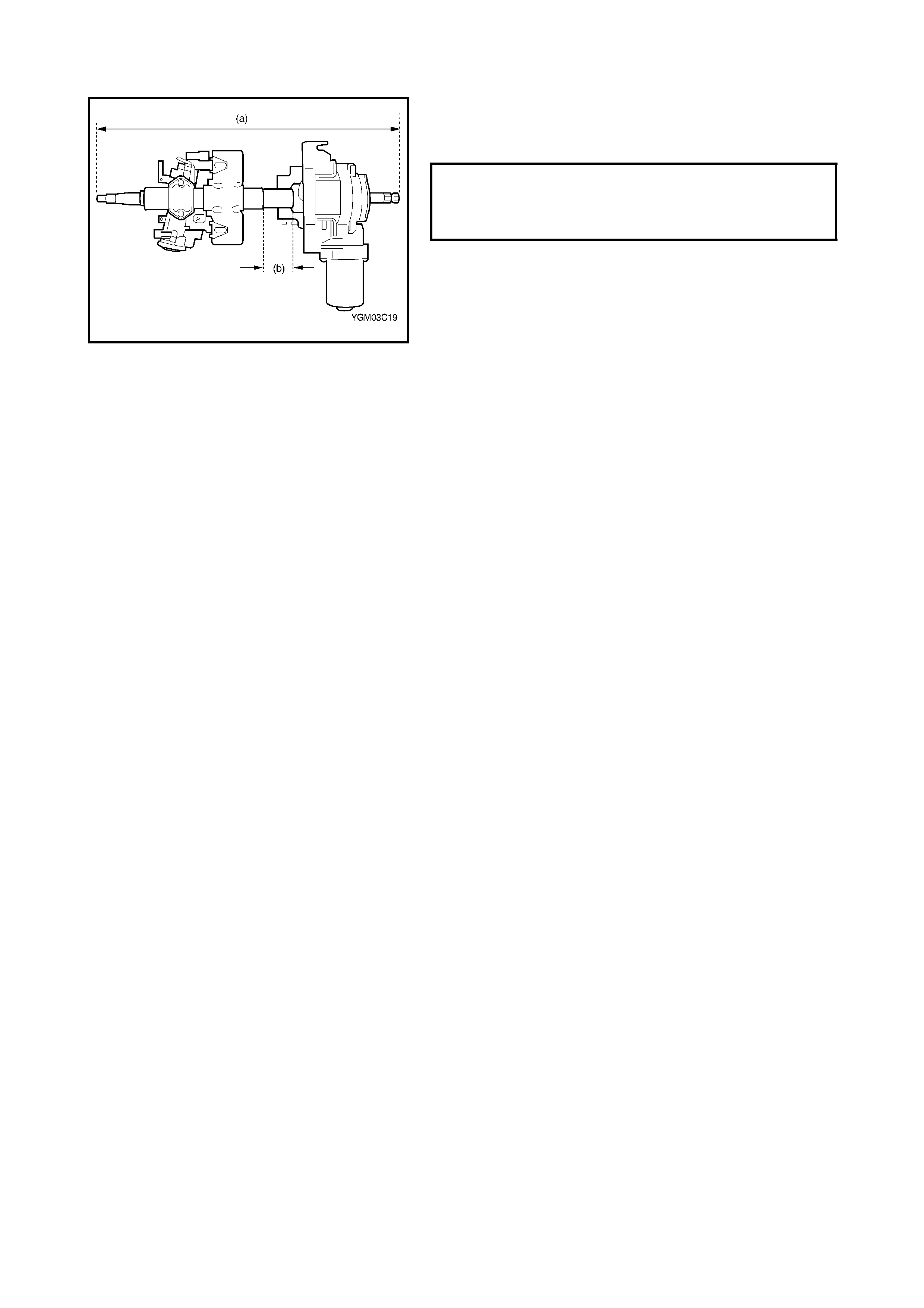
3. Take m eas urem ents (a) and (b) as shown.
If either is shorter than the specified length, replace the
column assem bly with a new one.
4. Check steering lower shaft joints and steerin g shaft for
any damage such as cracks, breakage, malfunction or
e xce ssiv e p lay.
If anything is found to be faulty, replace the whole
steeri ng colum n assembly.
5. Check the steering shaft for smooth rotation .
If found to be defective, replace the whole steering
column assembly.
6. Check the steering shaft and col umn to ensure it is not
bent, cracked or def ormed.
If found to be defec tive, replace.
STEERING SHAFT AND COLUMN
LENGTH (a)
(b) 49 1 - 494 mm
49 - 50 mm