
3C
SECTION 3C1 - STEERING WHEEL AND COLUMN (2004 UPDATE)
WARNING:
For vehicles equipped with a Supplemental Restraint (Air Bag) System:
• Service on and around the air bag sy stem components or wiring must be performed only by an
authorized HOLDEN deal er. Refer to “System Components and Wiring Location View and Connectors”
under “General Description” in Section 10B in order to confirm whether you are performing service on
or near the air bag system components or wiring. Please observe all WARNING s and “Serv i ce
Precautions” under “On- Vehicle Service” in Section 10B before perfo rming service on or around the air
bag system components or wiring. Failure to follow WARNINGs could result in unintentional activation
of the system or could render the system inoper ative. Either of these two conditions may result in
severe injury.
• Technical service work must be started at least 90 seconds after the ignition switch is turned to the
“LOCK” position and the negative cable is disconnected from the battery. Otherwise, the system may
be activated by reserv e energy in the Sensing and Diagnostic Module (SDM).
NOTE:
For the items not listed below, refer to the Section 3C.
On-Vehicle Service
Driver Air Bag (Inflator) Module
On-Vehicle Service
Driver Air Bag (Inflator) Module
REMOVAL
1) Disconnect negative cable at battery.
2) Disable air bag system. Refer to “Disabling Air Bag System”
in Section 10B.
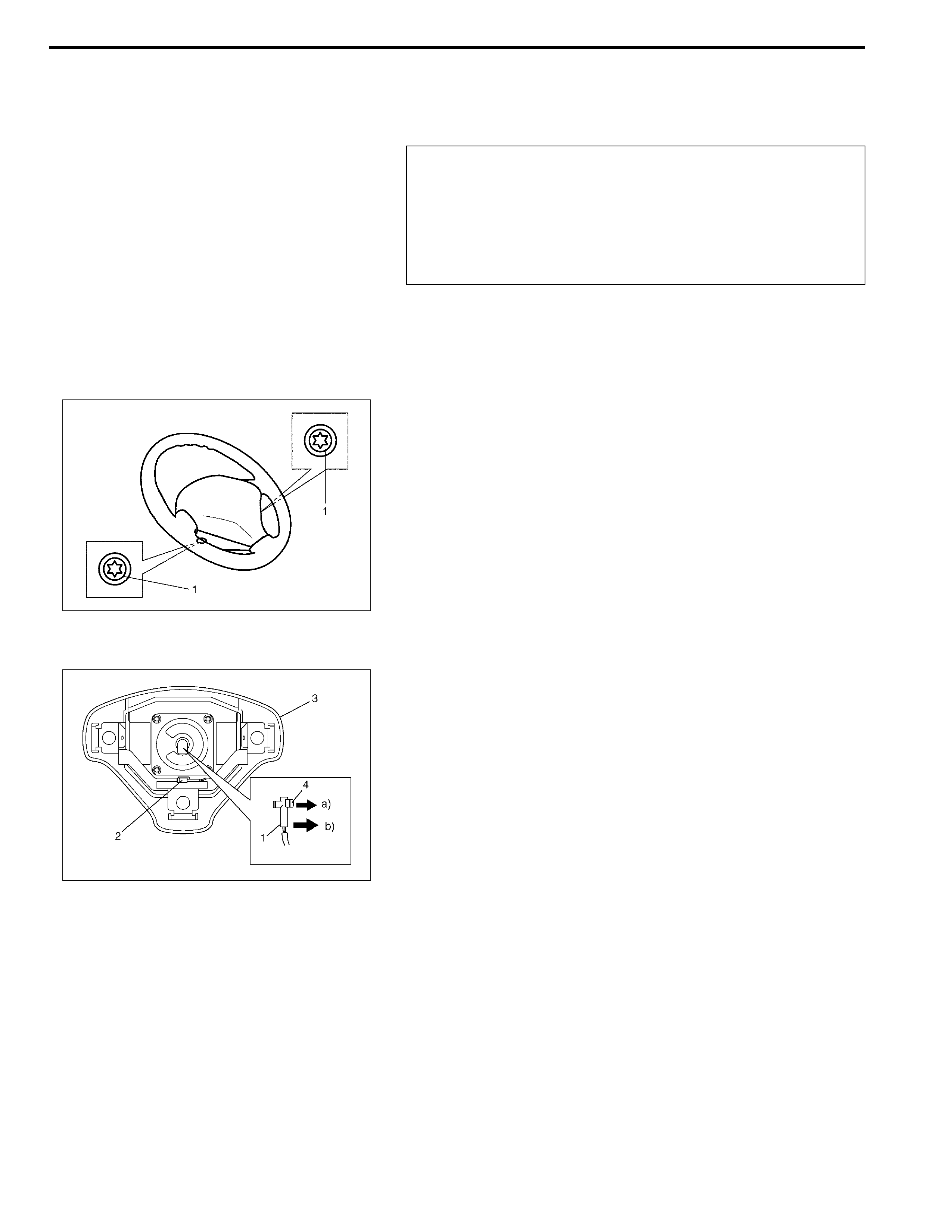
3) Loosen 2 bolts (1) mounting driver air bag (inflator) module
on its both side.
4) Remove driver air bag (inflator) module (3) from steering
wheel.
5) Disconnect driver air bag (inflator) module connector from
driver air bag (inflator) module as follows.
a) Unlock lock button (4).
b) Disconnect connector.
6) Disconnect horn connector (2).
WARNING:
When handling an air bag (inflator) module, be sure to
read “Service Precautions” in Section 10B and observe
each instruction. Failure to follow them could cause a
damage to the air bag (inflator) module or result in per-
sonal injury.
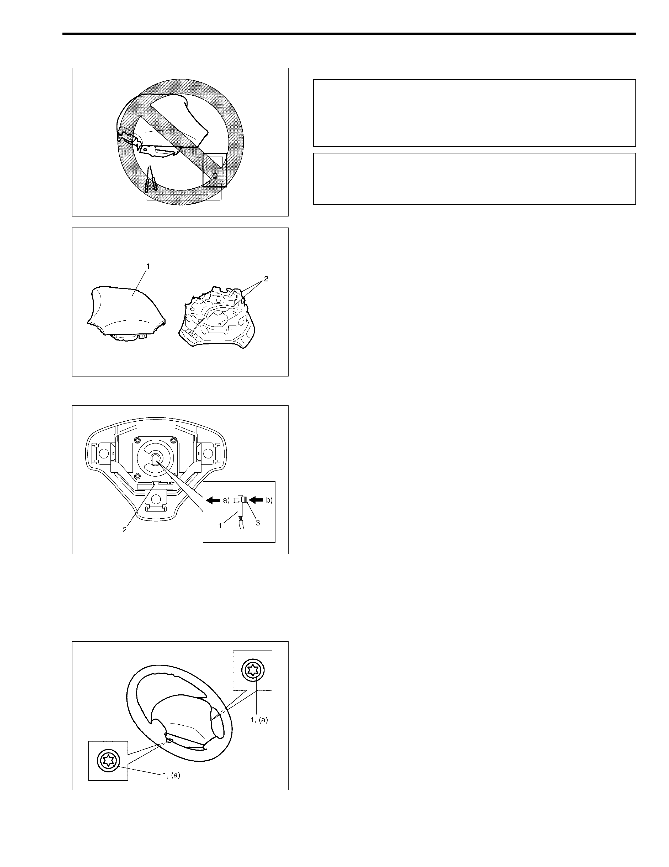
INSPECTION
Check air bag (inflator) module visually and if any of the following
is found, replace it with a new one.
• Air bag being deployed
• Trim cover (pad surface) (1) being cracked
• Wire harness or connector (2) being damaged
• Air bag (inflator) module being damaged or having been
exposed to strong impact (dropped)
INSTALLATION
1) Check that horn wire is connected to horn connector (2)
securely.
2) Connect driver air bag (inflator) module connector (1) to
driver air bag (inflator) module as follows.
a) Connect driver air bag (inflator) module connector.
b) Lock connector with lock button (3).
3) Install driver air bag (inflator) module to steering wheel, tak-
ing care so that no part of wire harness is caught between
them.
4) Make sure that clearance between module and steering
wheel is uniform all the way.
5) Tighten driver air bag (inflator) module mounting bolts (1) to
specified torque.
Tightening torque
Driver air bag (inflator) module mounting bolt
(a) : 9 N·m (0.9 kg-m, 6.5 lb-ft)
6) Connect negative cable at battery.
7) Enable air bag system. Refer to “Enabling Air Bag System” in
Section 10B.
WARNING:
Never disassemble driver air bag (inflator) module or
measure its resistance. Otherwise, personal injury may
result.
CAUTION:
If air bag (inflator) module was dropped from a height of
90 cm (3 ft) or more, it should be replaced.