SECTION 3D - FRONT SUSPENSION
1. GENERAL DESCRIPTION
2. DIAGNOSIS
2.1 STABILISER BAR AND/OR
BUSHING CHECK
Bar
Bushing
2.2 STRUT ASSEMBLY CHECK
2.3 SUSPENSION CONTROL
ARM / STEERING
KNUCKLE CHECK
2.4 SUSPENSION CONTROL
ARM BUSHING CHECK
2.5 SUSPENSION CONTROL ARM JOINT
CHECK
2.6 FRONT SUSPENSION
FASTENER S CH EC K
2.7 WHEEL, NUT AND
BEARING CHECK
3. ON-VEHICLE SERVICE
3.1 STRUT ASSEMBLY
Removal
Disassembly
Assembly
Installation
3.2 STABILISER BAR AND/OR
BUSHINGS
Removal
Installation
3.3 WHEEL HUB AND STEERING
KNUCKLE
Removal
Disassembly
Assembly
Installation
3.4 SUSPENSION CONTROL
ARM / BUS HING
Removal
Disassembly
Assembly
Installation
4. REQUIRED SERVICE MATERIAL
5. SPECIAL TOOLS
NOTE:
• All front suspension fasteners are important attaching parts that could affect the perfor-
mance of vital parts and systems. They must be replaced with items of the same part number
or w ith an equ ivale nt par t if re placem e nt beco m es nece ssa ry. Do no t use a replace m ent p ar t
of le sser quality or substitute design. Torque values must be used as s pe cified during reas-
sembly to assur e proper retention of the part.
• Never attempt to heat, quench or straighten any front suspension part. Replace it with a new
part or damage to the part may result.
Techline
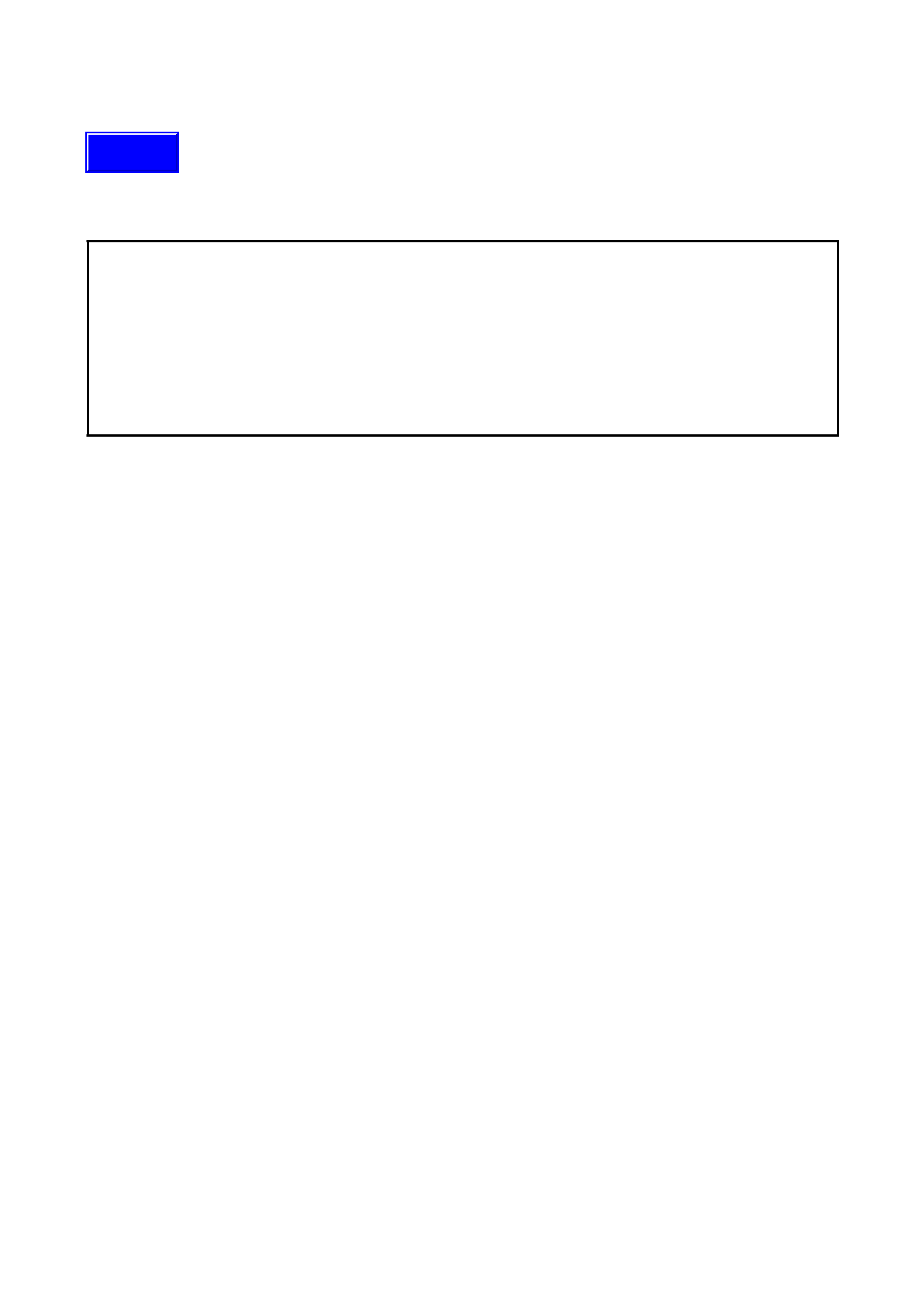
1. GENERAL DESCRIPTION
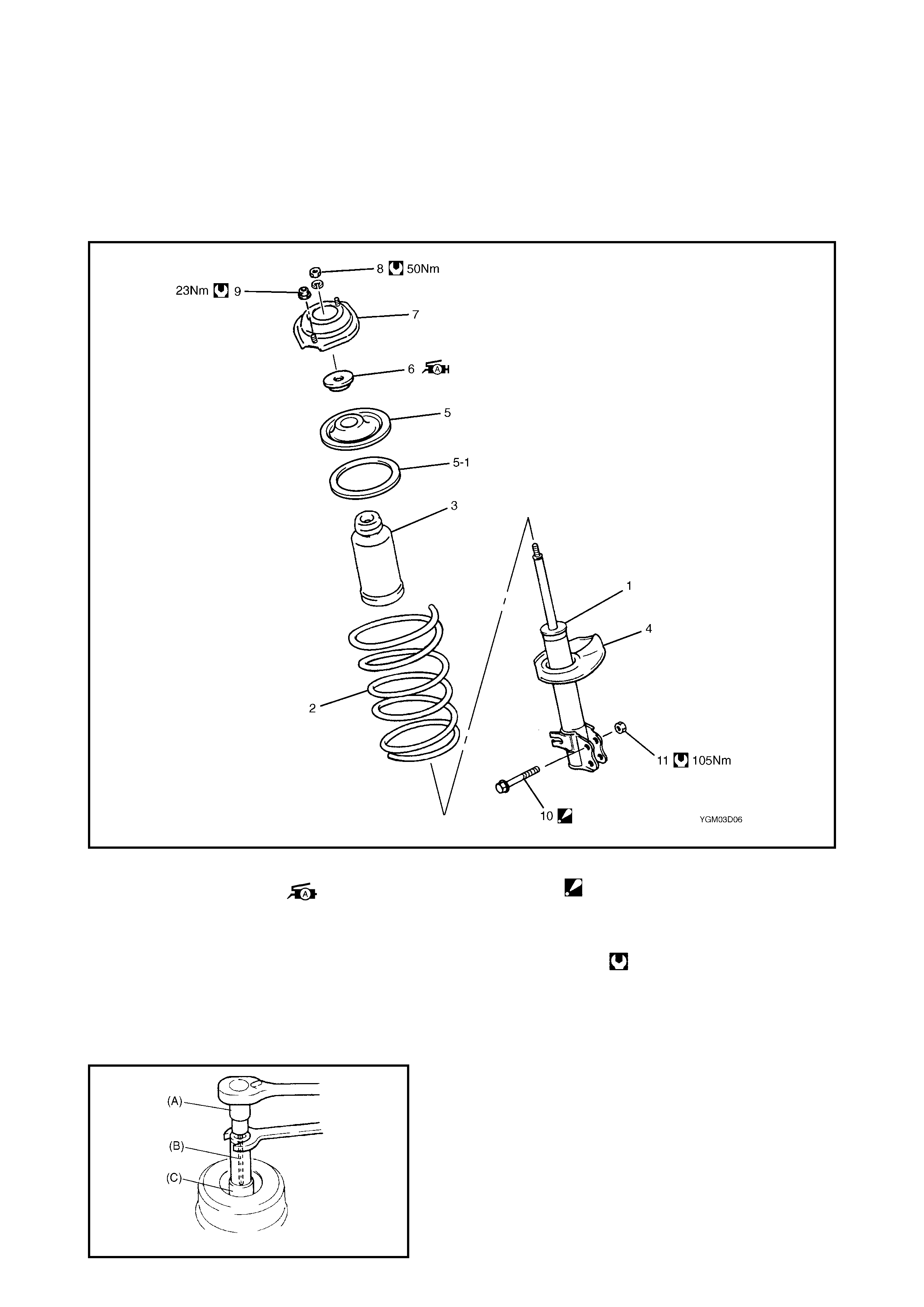
Legend
85Nm
FRONT
85Nm
60Nm
65Nm
8
5
11
4
9
3
2
10
175Nm
85Nm
85Nm
60Nm
65Nm
43Nm
105Nm
50Nm
23Nm
45Nm
4
97
5
2
8
1
6
3
175Nm
YGM03D02
1. Strut assem bly 6. Vehicle body 11. Paint mark (RH side only)
2. S tabilise r ba r 7. Drive sha ft Tig h tening tor que
3. Steering knuckle 8. Tie rod Do not reuse.
4. Wheel 9. Brak e disc
5. Suspension cont rol ar m 10. Paint mark
2. DIAGNOSIS
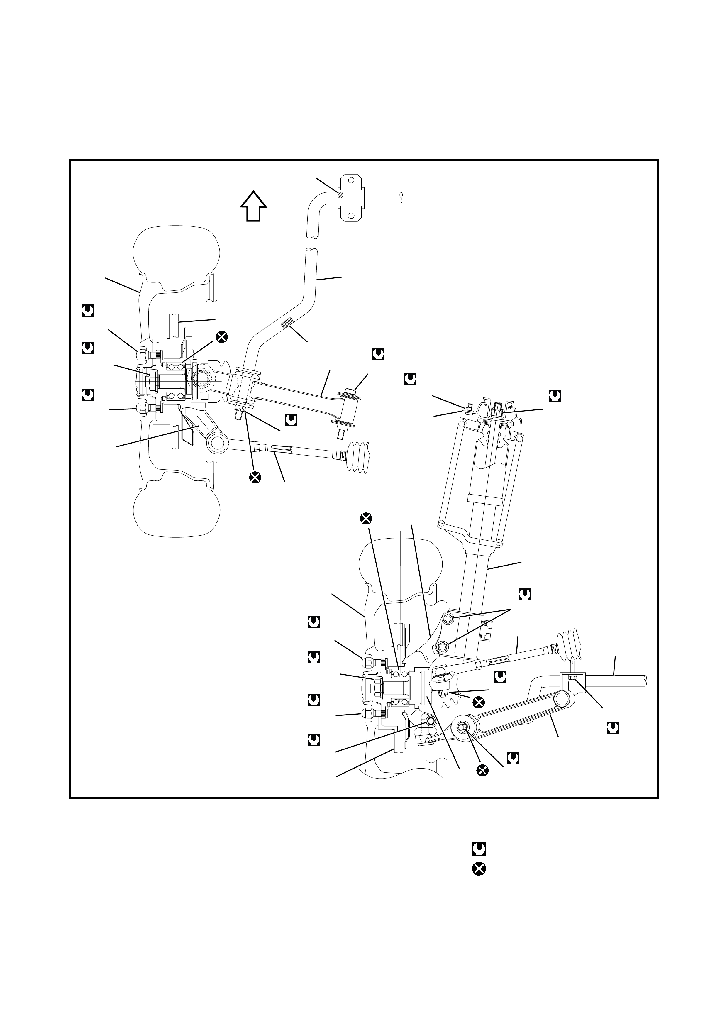
2.1 STABILISER BAR AND/OR BUSHING CHECK
BAR
Inspect f or damage or deformation.
If defectiv e, replac e.
BUSHING
Inspect f or damage, wear or deterioration.
If defectiv e, replac e.
2.2 STRUT ASSEMBLY CHECK
• Inspect strut for oil leakage, damage or deformation.
• If strut is found to be faulty, replace it as a complete
assembly, as it can not be disas sembled.
• Inspect strut function, referring to the following proce-
dures:
1. Check and adjust tyre pressures as spec ified.
2. Bounce the vehicle body 3 or 4 times continuously by
pushing down on the front end on the side to be
checked.
3. Apply the same amount of force to eac h push and note
strut resistance bot h when pushed and on re boundi ng.
4. Note how many times the vehicle body rebounds
before coming to a stop. Do the same for the strut on
the other side.
5. Compare st rut resistance and t he number of rebounds
on the right side with those on the left. They should be
the same. When the struts are in good condition, the
vehicle should stop bouncing or have only one or two
small reboun ds mom ents after pushing ceases.
If t he condition of the str ut s is i n doubt, compare them with
a known-good vehicle or st rut.
• Inspect strut beari ng for wear, abnor mal noise or gr ip-
ping. If defective, replace.
• Inspect spring seat for cracks or deformation.
If defective, replace.
• Inspect bump stopper for deterioration.
If defective, replace.
• Inspect strut mount for wear, cracks or deformation.
If defective, replace.
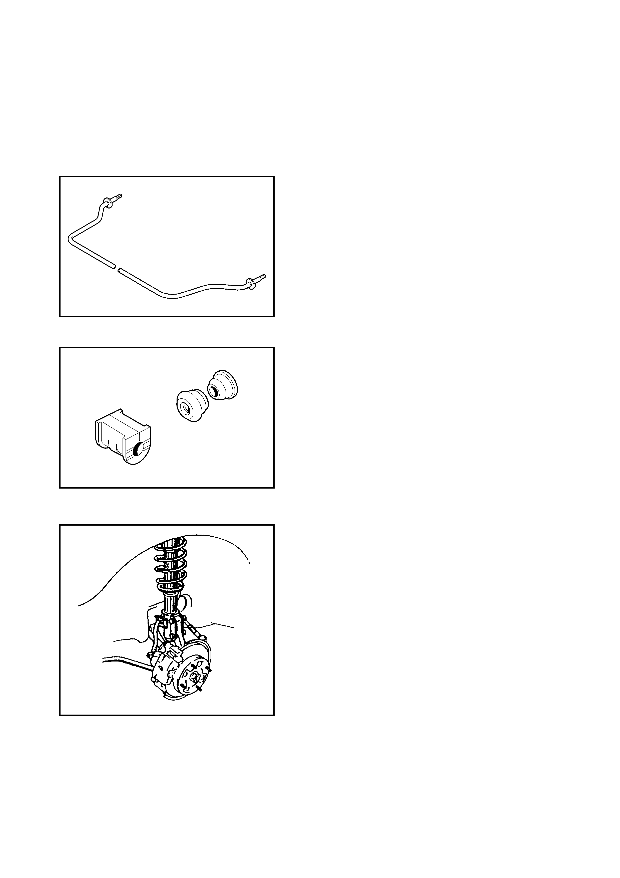
2.3 SUSPENSION CONTROL ARM / STEERING KNUCKLE CHECK
Inspect the suspension control arm/steering knuckle for
cracks, deformation or damage.
If defective, replace.
2.4 SUSPENSION CONTROL ARM BUSHING CHECK
Inspect suspension control arm bush for damage, wear or
deterioration.
If defective, replace.
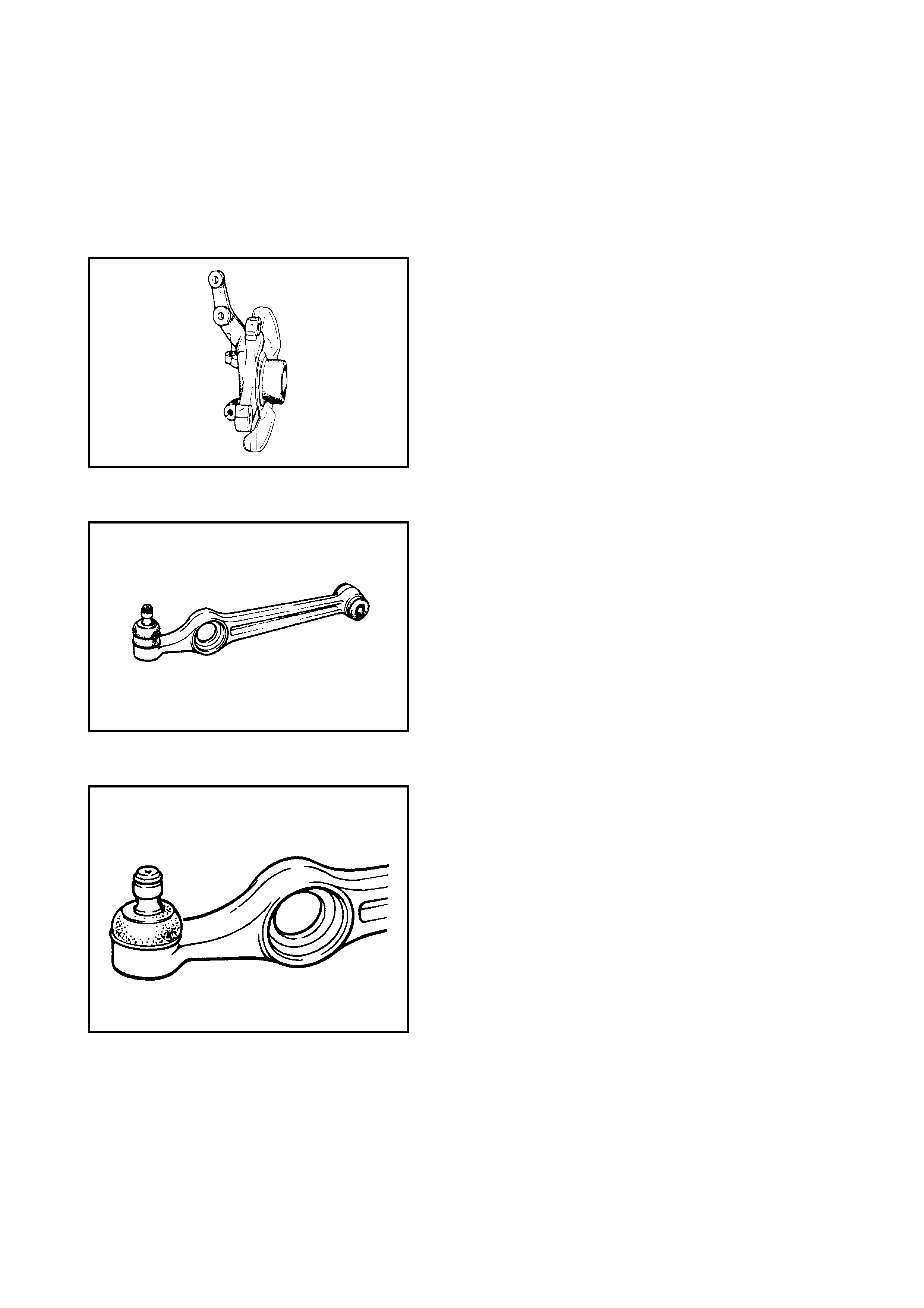
2.5 SUSPENSION CONTROL ARM JOINT CHECK
• Check for smooth rotation.
• Inspect ball stud for damage.
• Inspect dust cover for damage.
NOTE: Suspension control arm and arm joint cannot be
separated.
If there is any damage to either the control arm assembly or
the arm joint, they must be replaced as a complete unit.
2.6 FRONT SUSPENSION FASTENERS CHECK
Check each bolt and nut retaining the suspension parts for
tightness. Tighten any loose fasteners to specified torque,
refer to 1. GENERAL DESCRIPTION in this Section.
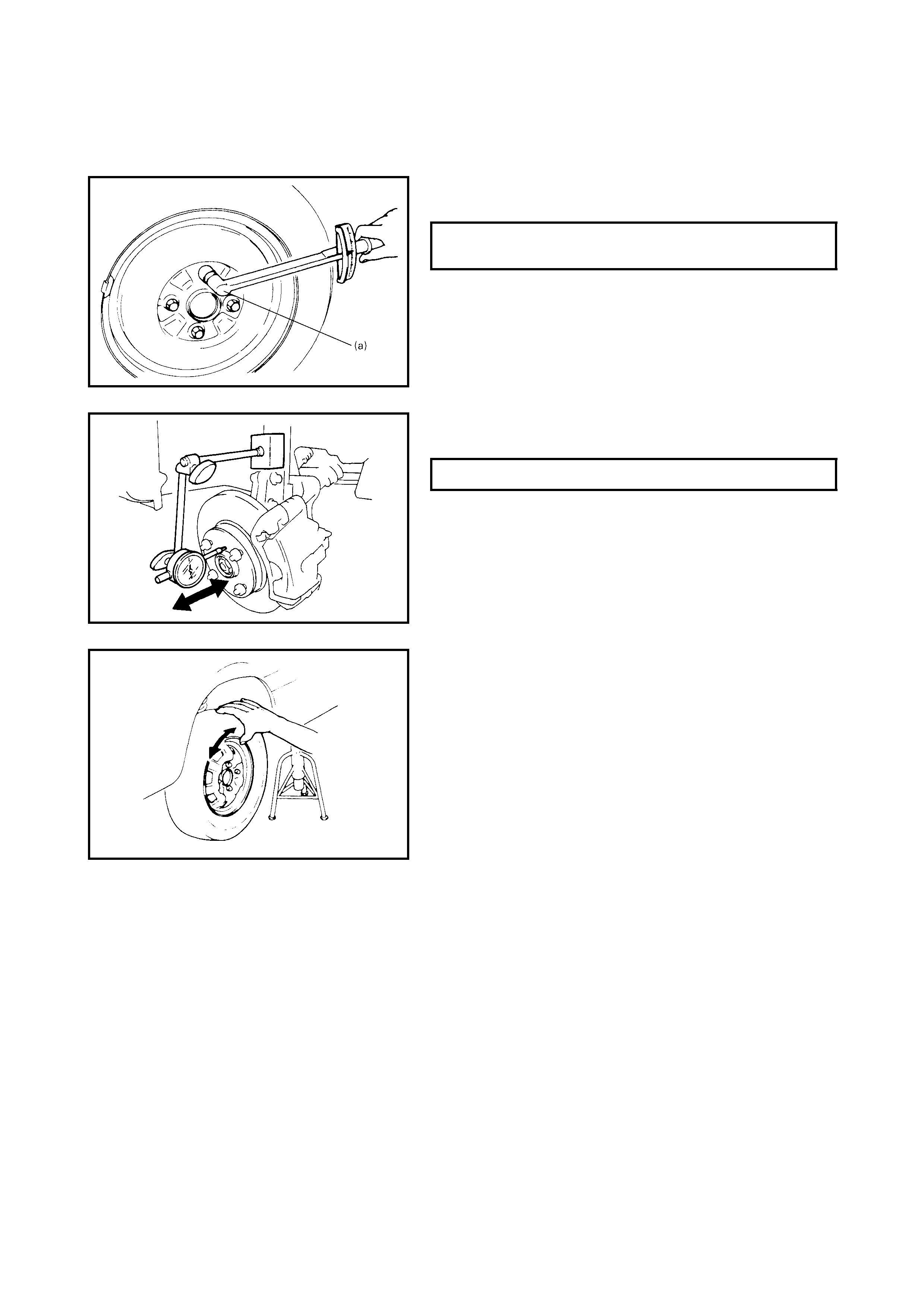
2.7 WHEEL, NUT AND BEARING CHECK
• Inspect each wheel for den ts, distor t ion and cracks.
A damaged wheel must be replaced.
• Che ck wheel nuts for tightness and retighten to specifi-
cation where necess ar y.
• Check wheel bearing for wear. Attach a dial gauge to
wheel hub to measure thr ust play.
• Rotate wheel and check wheel bearing for noise and
smooth rotation.
If defective, replace bearing.
WHEEL NUT (A)
TORQUE SPECIFICATION 85 Nm
THRUST PLAY LIMIT 0.1 mm
3 . ON-VEHICLE SE RVICE
3.1 STRUT ASSEMBLY
Legend
REMOVAL
NOTE: When disassembling the strut assembly, loosen
strut nut a little using special tools 09900-00411 (A),
09900-00414 (B) and 09945-26010 (C) before removing
strut assembly from vehicle. This will make disassembly
easier. Note, however, nut must not be removed at this
point.
1. Hoist vehicle, allowing front suspension to hang free.
2. Remove wheel.
1. S t rut as sembly 6. Strut bearing
:Apply lithium grease
to bearing.
10. Strut bracket bolt
: Ins e rt from fro n t o f vehic le.
2. C o il s pr ing
3. B um p s topper 11. Strut bracket nu t
4. Coil spring lower seat 7. Strut support Tightening torque
5. Coil spring upper seat 8. Strut nut
5-1. S pring seat 9. Strut support nut
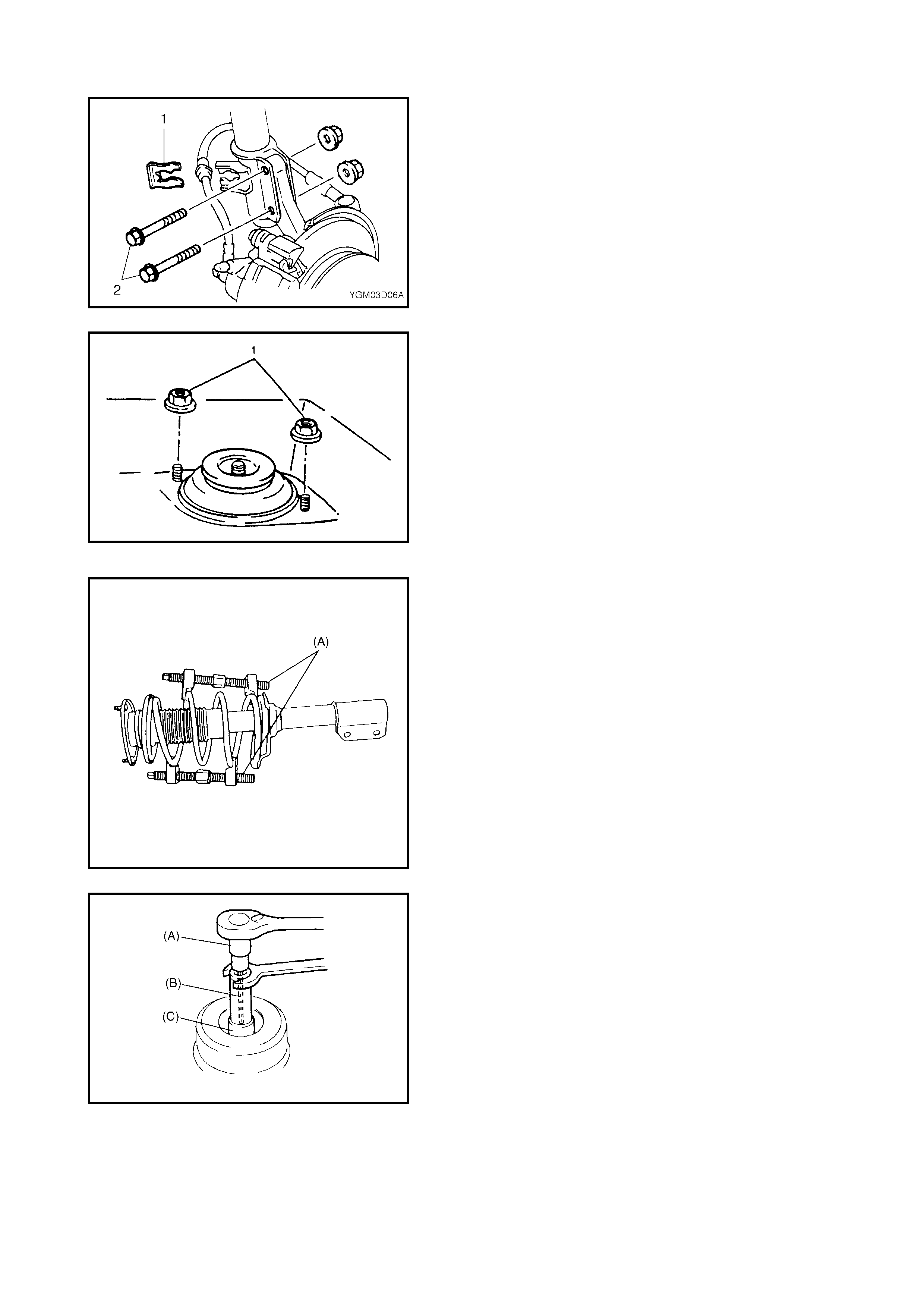
3. Remove the E-ring (1) securing the brake hose and
take the brake hos e off the strut bracket as shown.
4. Remove the ABS wheel speed sensor harness clamp
bolt from the strut (if equipped).
5. Remove the strut bracket bolts (2).
6. Remove the strut support nuts (1).
NOTE: Support the strut assembly by hand so that it will
not fall off.
7. Remove strut assemb ly.
DISASSEMBLY
1. With spec ial tool 09940-71431 ( A) placed on the spring
as shown, turn special tool bolts alternat ely unt il spring
tension is released. Tension is released sufficiently
when t he st rut can be eas ily rotated while t he spring is
held stationary.
2. Remove the strut nut with special tools, 09900-00411
(A), 09900-00414 (B ) and 009945-260 10 (C) while coil
spring is compressed.
3. Di sasse mble stru t as sembly.
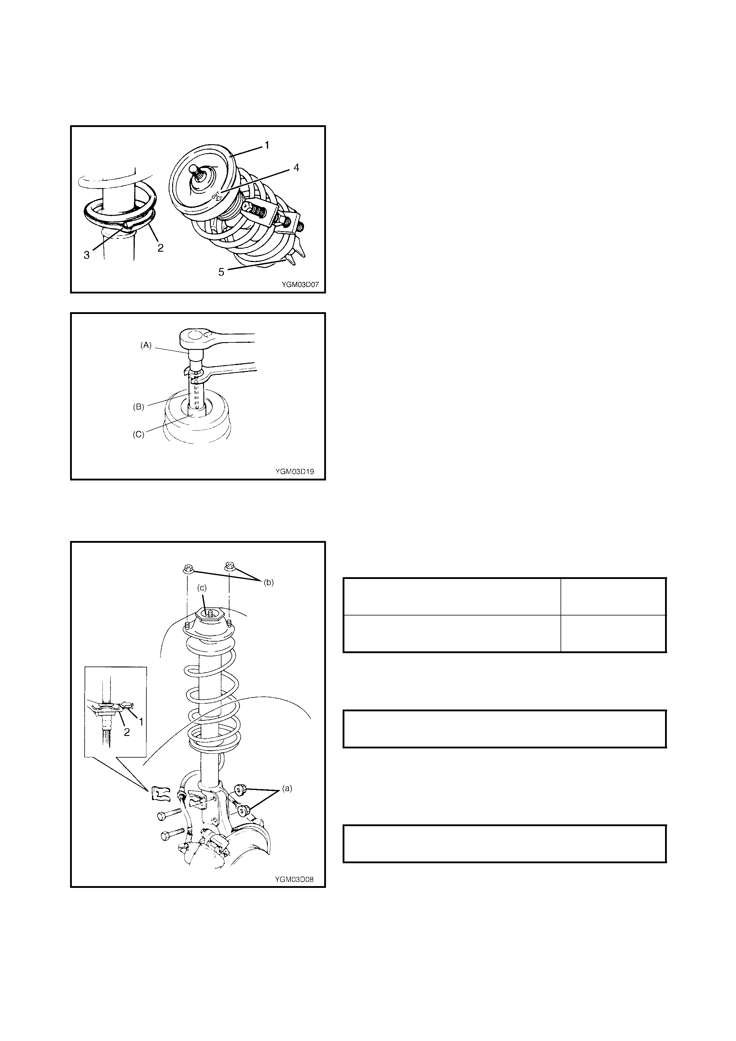
ASSEMBLY
For assembly, reverse disassembly procedure, noting the
following instructions.
• Mate spring end with stepped part (3) of spring lower
seat (2) as shown.
• Install the spring upper seat (1) on the coil spring align-
ing the “OUT” mark (4) on spring upper seat with the
centre of the strut mounting bracket (5).
• Install bearing, strut support and strut unit in this
sequence.
• Fit strut nut loosely at this step using special tools
09900-00411 (A), 09900-0414 (B) and 09945-26010
(C).
INSTALLATION
Install strut assembly by reversing removal procedure, not-
ing the following instructions.
• Insert bolts in the direction shown in figure.
• Tighten all fasteners to specified torque.
• Tighten strut nut to specified torque using special tools
09900-00411 (A), 09900-0414 (B) and 09945-26010
(C).
NOTE:
• Do not twist brake hose when re-installing.
• Install E-ring (1) fully into bracket (2) as shown.
• Tighten wheel nut to specified torque.
• After installation, confirm wheel alignment, refer to
Section 3A FRONT END ALIGNMENT.
STR UT BRACKET NUT (a)
TORQUE SPECIFICATION 105 Nm
STRU T SUPPORT NUT (b)
TORQUE SPECIFICATION 23 Nm
STR UT NUT (c)
TORQUE SPECIFICATION 50 Nm
WHEEL NUT
TORQUE SPECIFICATION 85 Nm
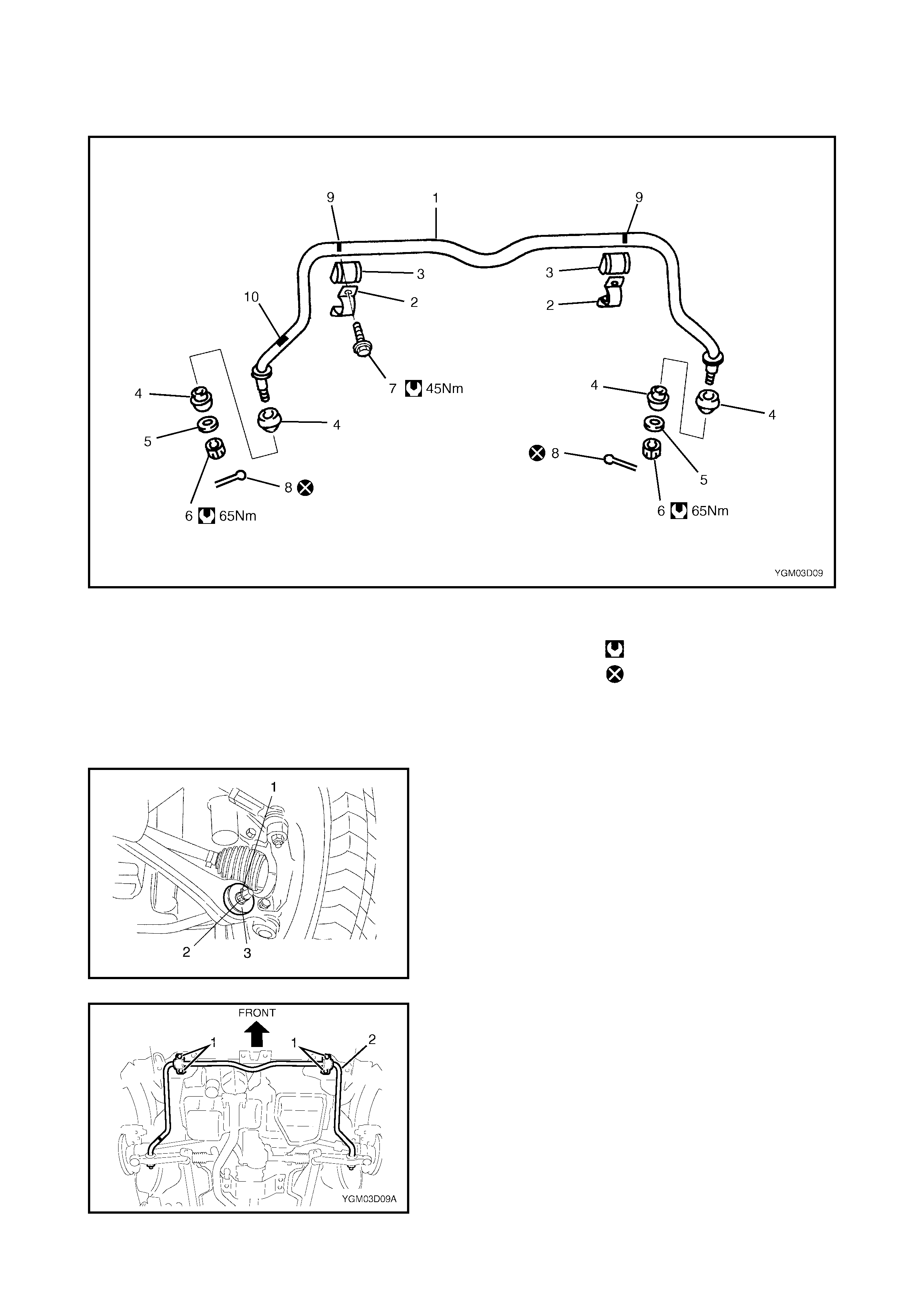
3.2 STABILISER BAR AND/OR BUSHINGS
Legend
REMOVAL
1. Hoist vehicle and allow the front suspension control
ar m s to hang free.
2. Remove the front wheels.
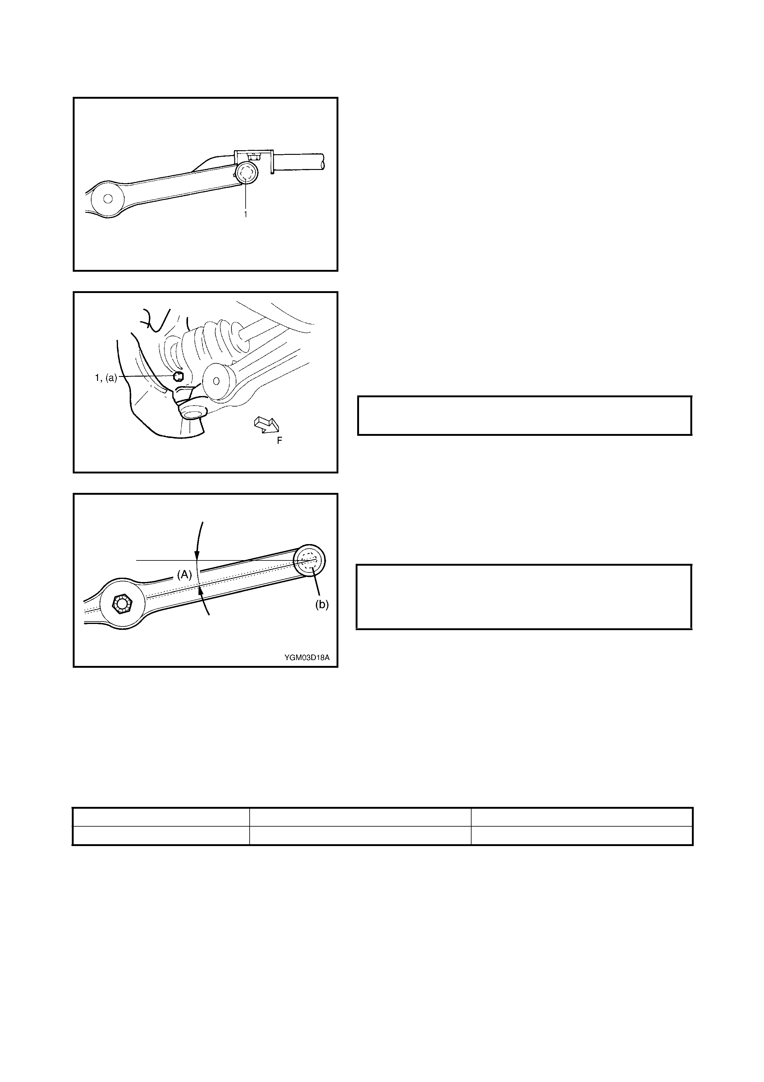
3. Remove the stabiliser bar split pins (1), nut (2) and
washer (3).
4. Remov e the s tabiliser bar mounting bracke t bolts (1).
5. Remov e the s tabiliser bar (2).
NOTE: If the stabiliser bar removal is difficult, refit front
wheels and lower the vehicle until the tyres contact the
ground (compressing t he suspension).
1. Stab i lis e r b ar 6. Stabilise r b ar nu t 10. Paint ma rk ( R H si de )
2. Mount bra cket 7. Stabilise r ba r mounti n g T igh t en ing tor qu e
3. Mount bus hi ng bracke t bolt Do not reuse.
4. Bu sh in g 8. Sp lit pin
5. Washer 9. Paint mark
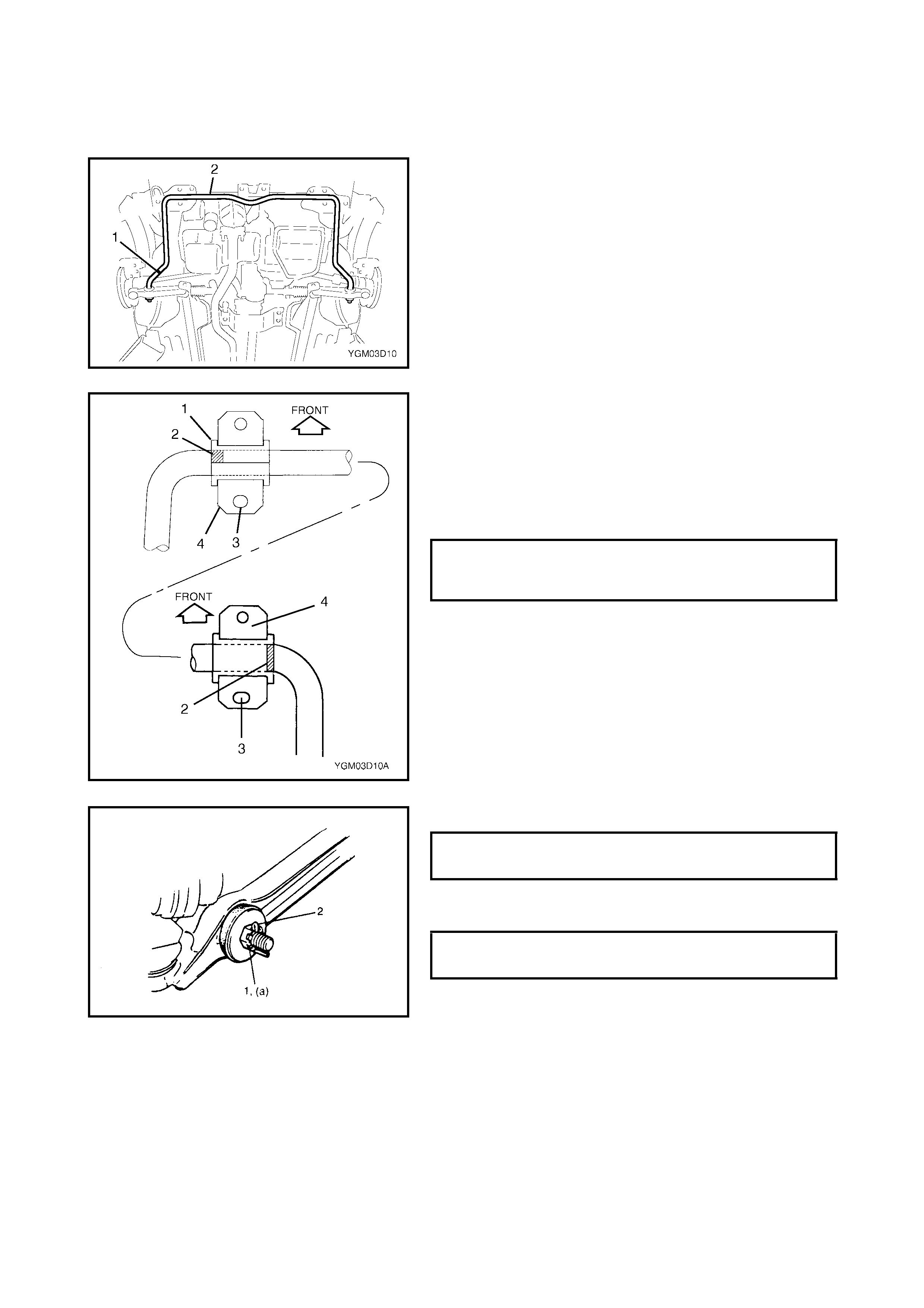
INSTALLATION
For installation, reverse removal procedure, noting the fol-
lowing in s tructions.
• When installing the stabiliser bar (2), ensure that the
paint mark (1) is on the RH side of the ve hicle.
• Align the outside edge (1) of the mount bushing with
the outs ide edge (2) of the pai nt mar k as shown in the
figure.
• Install the mount brackets (4) with the oblong hole (3)
towards the rear.
• Tighten the stabiliser bar mounting bracket bolts to
specified torque.
• Tighten the stabiliser bar nut (1) to specified torque.
• Install the new split pins (2) as shown.
• Tighten wheel nuts to specified torque.
STABILISER BAR MO UNTING
BRACKET BOLT
TORQUE SPECIFICATION 45 Nm
STABILISER BAR NUT (a)
TORQUE SPECIFICATION 65 Nm
WHEEL NUT
TORQUE SPECIFICATION 85 Nm
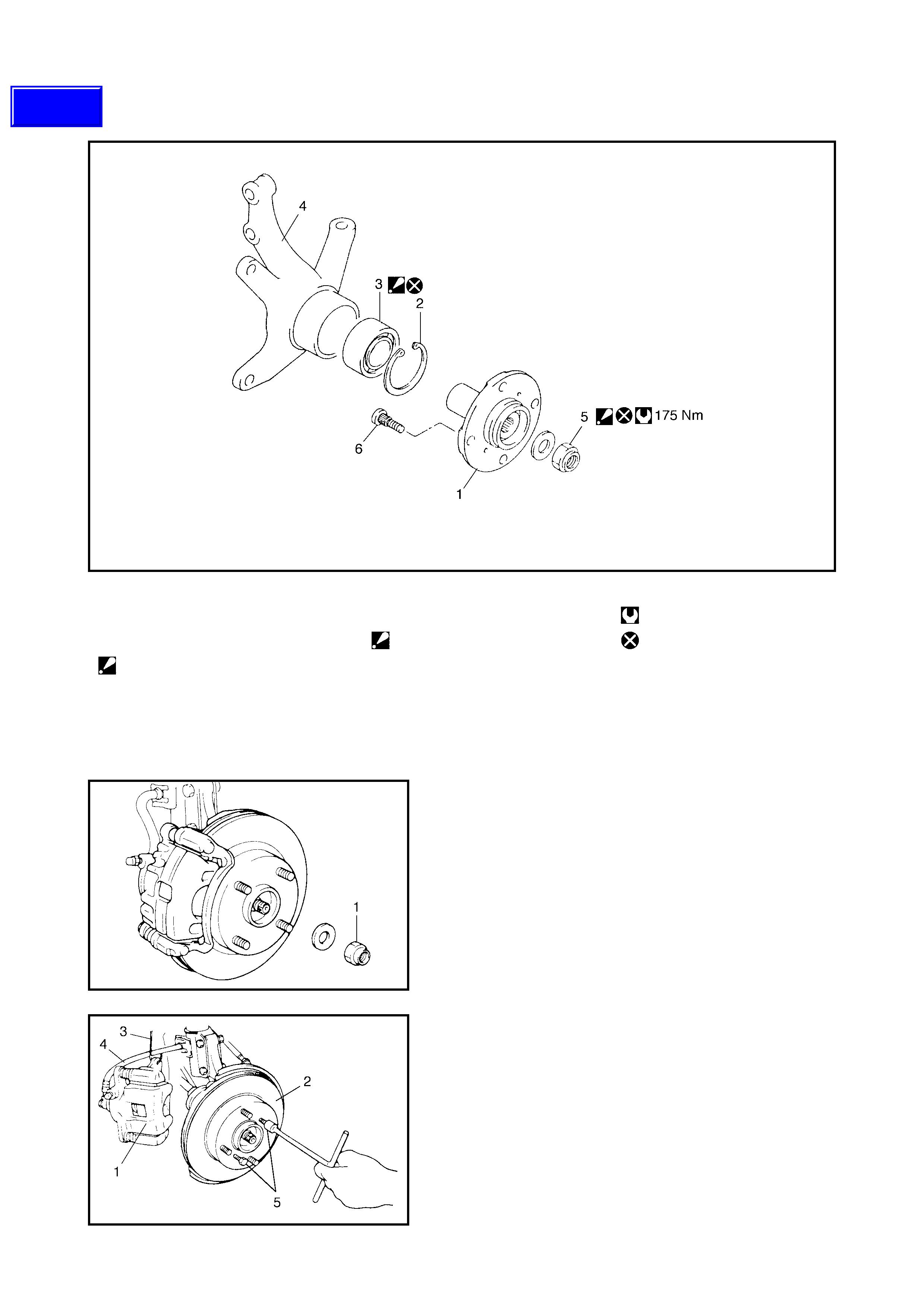
3.3 WHEEL HUB AND STEERING KNUCKLE
Legend
REMOVAL
1. Hoist vehicle and remove wheel.
2. Unstake drive shaft nut (1).
3. Depress brake pedal and keep depressed while
removing drive shaft nut (1) and washer.
4. Remov e caliper carrier bolts.
5. Remove caliper (1) wi th carrier.
NOTE: Hang removed caliper with a wire hook or similar
(3) to pr event the brake hose (4) from bending and twist ing
or being pulled e xcessivel y.
Do not operate brake pedal with pads remove d.
6. Remove bra ke disc (2) by pulling on tw o 8m m bolts (5)
fitted as shown in figure.
1. Fron t wheel hub 4. S t eering knuckle Tightenin g torque
2. Circlip 5. Drive shaft nut.
: Stake, after tightening. Do not reuse.
3. Wheel bearing.
: Face grooved rubber seal
side to wheel h ub. 6. Hub bolt
Techline
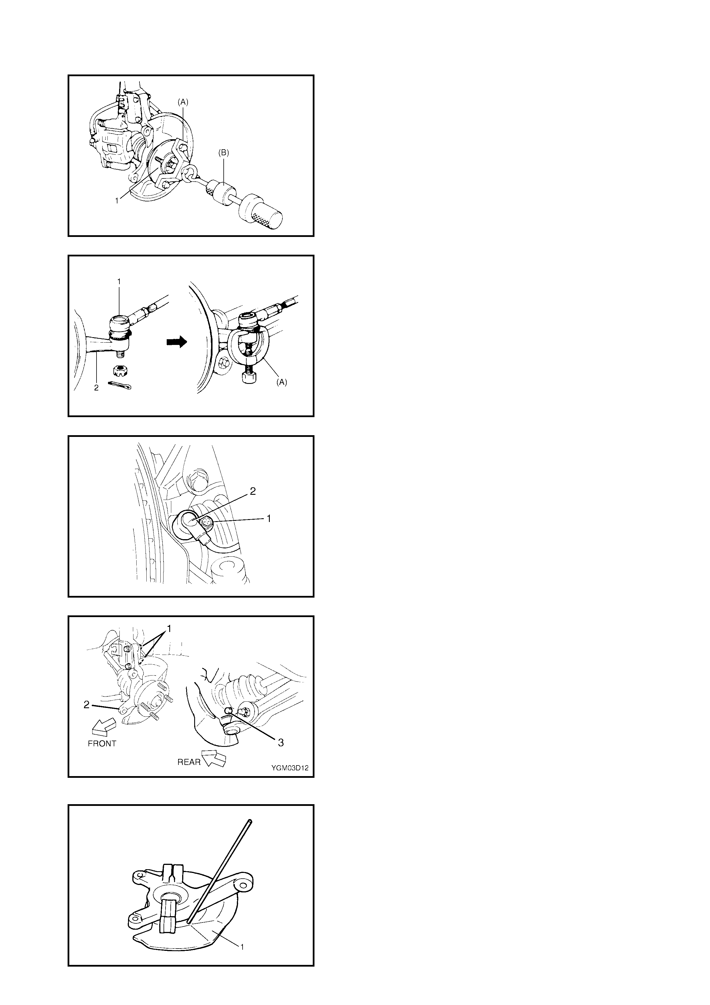
7. Pull out the wheel hub (1) using special tools 09943-
17912 (A) and 09942-15 511 (B).
CAUTION: When whee l hub is removed, ensure wheel
beari ng s are replaced as a set.
8. Remove t he tie rod split pin and castle nut and discon-
nect the tie rod end (1) from the steering knuckle (2)
using special tool 09913-65210 (A).
9. Remove the wheel speed sensor moun ting bolt (1) and
remove the wheel speed sensor (2) from the steering
knuckle (if equi pped wit h ABS).
10. Loose n the strut bracket nuts (1).
11. Remove the ball joint bolt (3).
12. Remove the strut bracket bolts from the strut bracket
then remove the s teerin g knuckle (2).
DISASSEMBLY
1. Unstake and remove the dust cover (1).
2. Remove the wheel bear ing circlip.
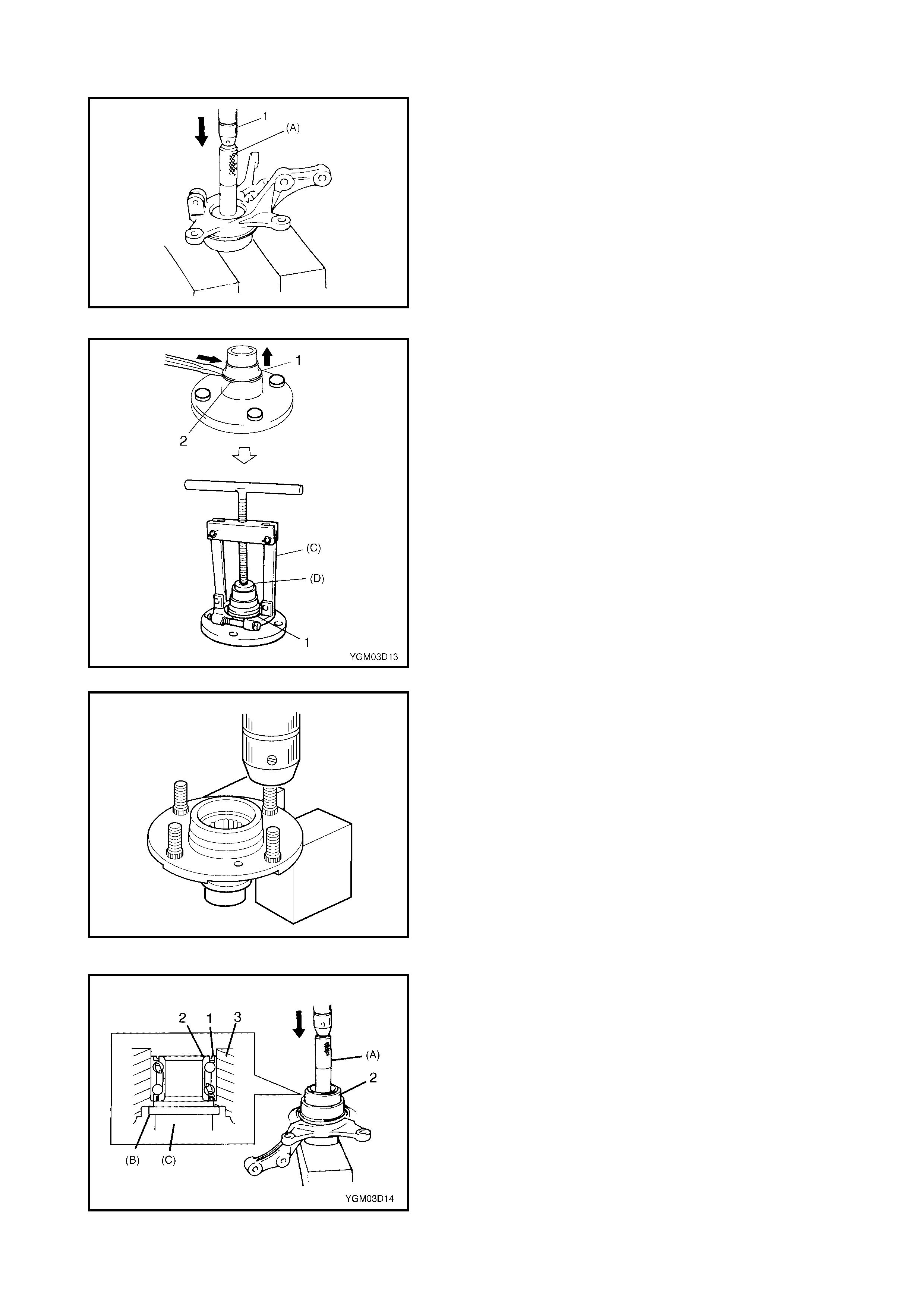
3. Using a hydraulic press (1) and special tool 09913-
75520 (A), remove the wheel bearing.
CAUTION: When installing a wheel bearing, always
use a new one.
4. Remove the wheel bearing outside inner race (1) as
shown by firstly hammering lightly at three locations
around it, taking care not to cause damage to the
seating part (2) of the wheel hub, then using special
tools 09913-65 810 (C) and 09926-58010 (D).
5. Remove the hub bolts (1) with hydraulic press or
coppe r hamm er.
CAUTION: Never remove the hub bolts unless
replacement is necessary.
Be sure to use new bolts for replacem en t.
ASSEMBLY
1. Face the rubber seal side (1) of t he new wheel b eari ng
(2) upward as shown in figure and press-fit it into the
steering knuckle (3) using special tools 09913-75510
(A), 09926-68310 (B) and 0995 1-18210 (C).
CAUTION: When replac ing the bearing , inner races o r
outer race, always replace them as a complete set.
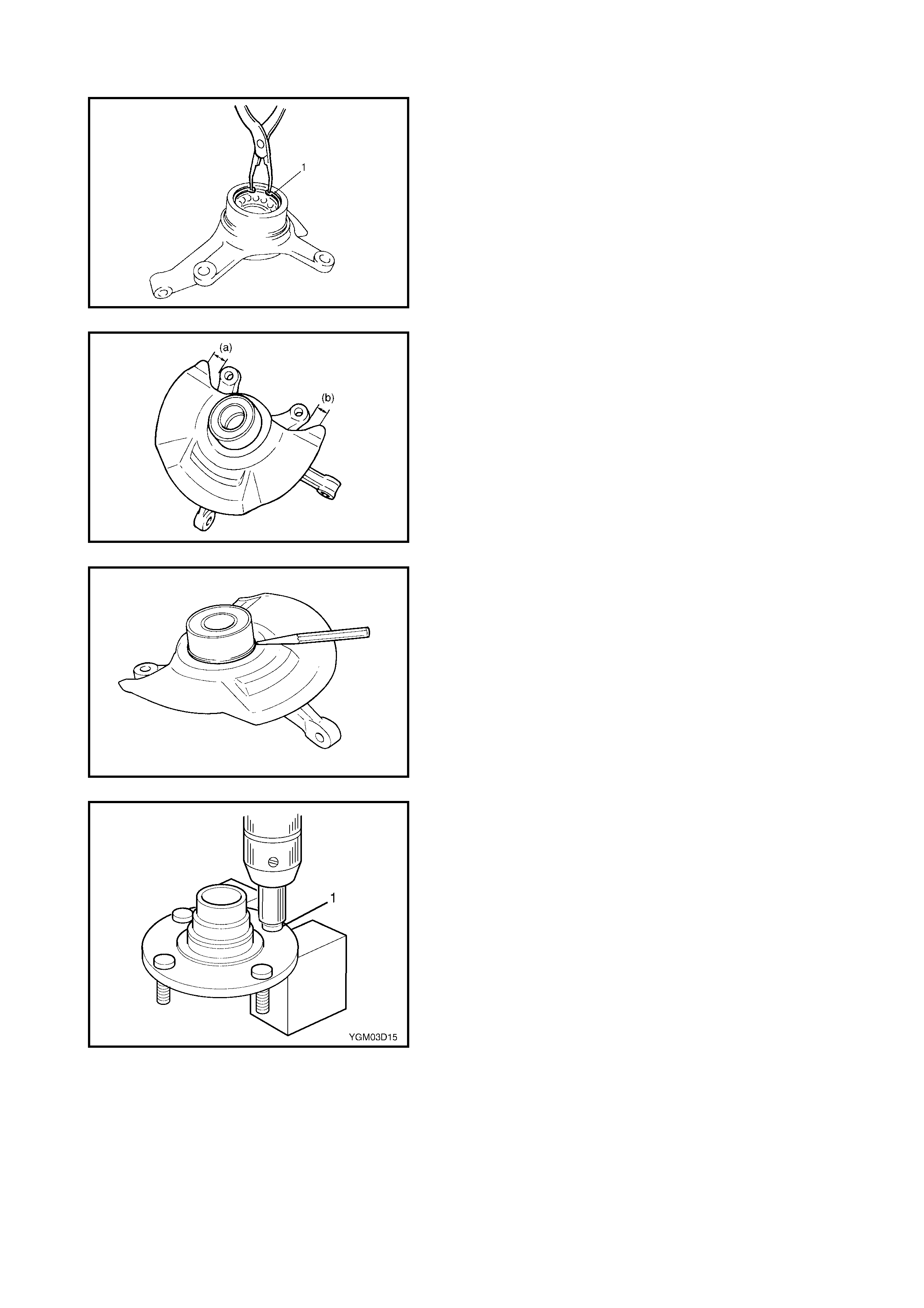
2. Install t he wheel bearing cir clip (1).
3. Press in the d ust cove r so that the dimensions (a) a nd
(b) are equal as shown in figure.
CAUTION: When pressing in the dust cover, take ca re
not to defo rm it.
4. Stake dust cover wi th a punch.
5. Inser t the new stud b olt (1) in the hub hole. Ro tate the
stud bolt slowly to ensure that serrations are aligned
with those made by the or iginal bolt.

INSTALLATION
For installation, reverse removal procedure, noting the fol-
lowing in s tructions.
•Using special tools 09913-75810 (A) and hydraulic
press, press-fit the wheel hub (1) into the wheel bear-
ing (2).
•Appl y grease lightly to the contac t p ar t (1) of the whe el
bearing and drive shaft.
(A): Lithium grease
•Install the ball j oint bolt (1) from the direction as s ho wn.
•Tighten the suspension arm ball joint bolt (1) to speci-
fied torque.
•Tighten the strut brac ket nuts (2) t o specified t orque.
•Install the wheel speed sensor (1) (if equipped with
ABS).
SUSPENSION ARM BALL JOINT BOLT (a)
TO RQUE SPECIF ICATION 60 Nm
STR UT BRACKET NUT (b) 105 Nm
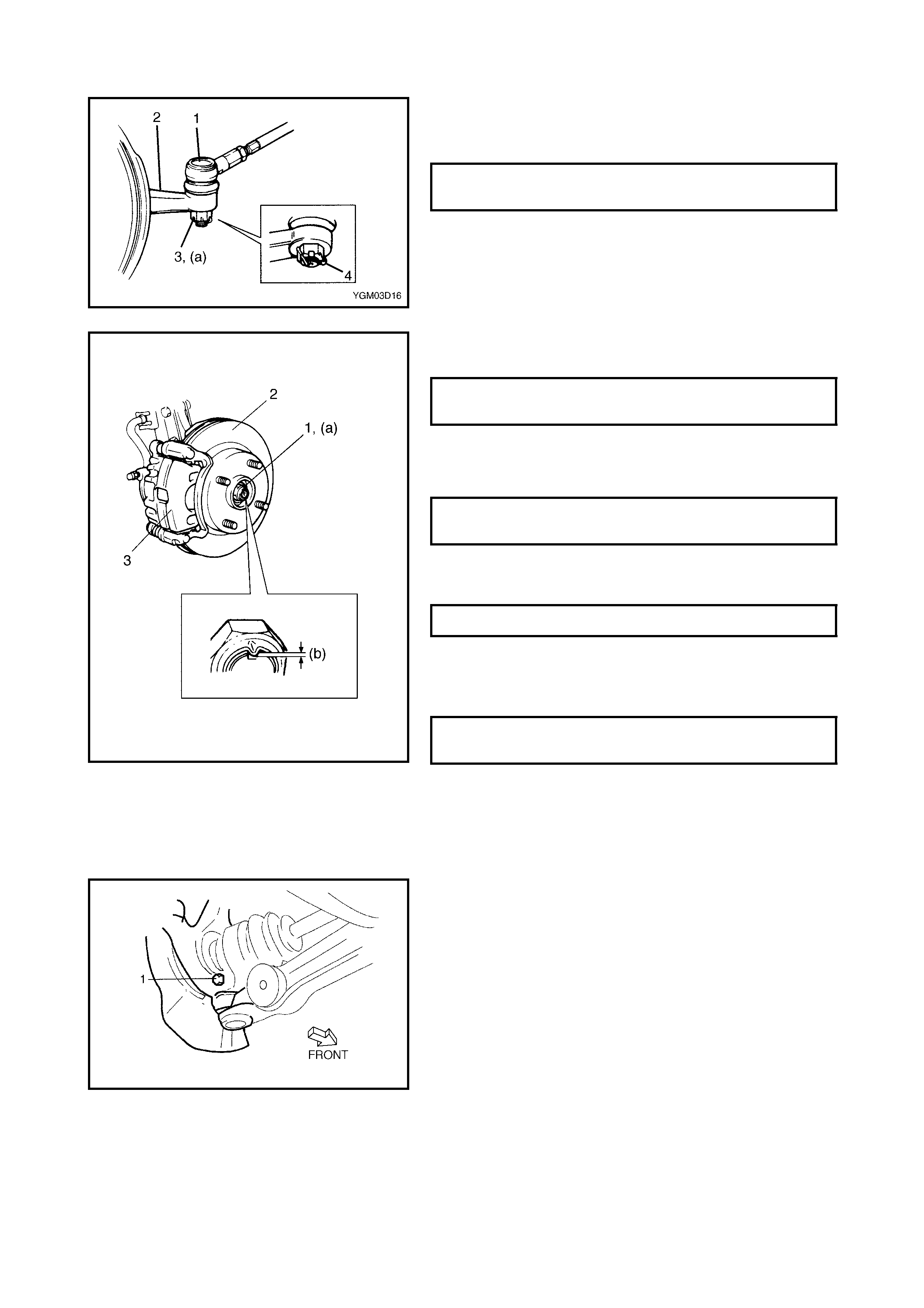
• Connect the tie rod end (1) to the steering knuckle (2)
and tighten tie rod end castle nut (3) to specified
torque.
• Install a new split pin (4) and bend pin ends securely
against nut as shown.
• Install the brake disc (2) and the brake caliper (3) and
tighten the brake caliper bolt to specified torque.
• Depress the foot brake pedal and hold it there.
Install new drive shaft nut (1) and washer and tighten to
specified torque.
CAUTION: Never reuse drive shaft nut (1).
• Stake drive shaft nut (1) as shown.
CAUTION: Take care while staking nut. If a split
occurs in staked area of nut replace it with a new one.
• Fit wheel and tighten wheel nut to specified torque.
3.4 SUSPENSION CONTROL ARM / BUSHING
REMOVAL
1. Remove the stabiliser bar. Refer to 2.2 STABILISER
BAR AND/OR BUSHINGS in this Section.
2. Remove the suspens ion control arm ball joint bolt (1).
TIE ROD END CASTLE NUT (a)
TORQUE SPECIFICATION 43 Nm
BRAKE CALIPER BOLT
TORQUE SPECIFICATION 85 Nm
DRIVE SHAFT NUT ( a)
TORQUE SPECIFICATION 175 Nm
STAKE SPECIFICATION (b) 0.5 mm OR MORE
WHEEL NUT
TORQUE SPECIFICATION 85 Nm
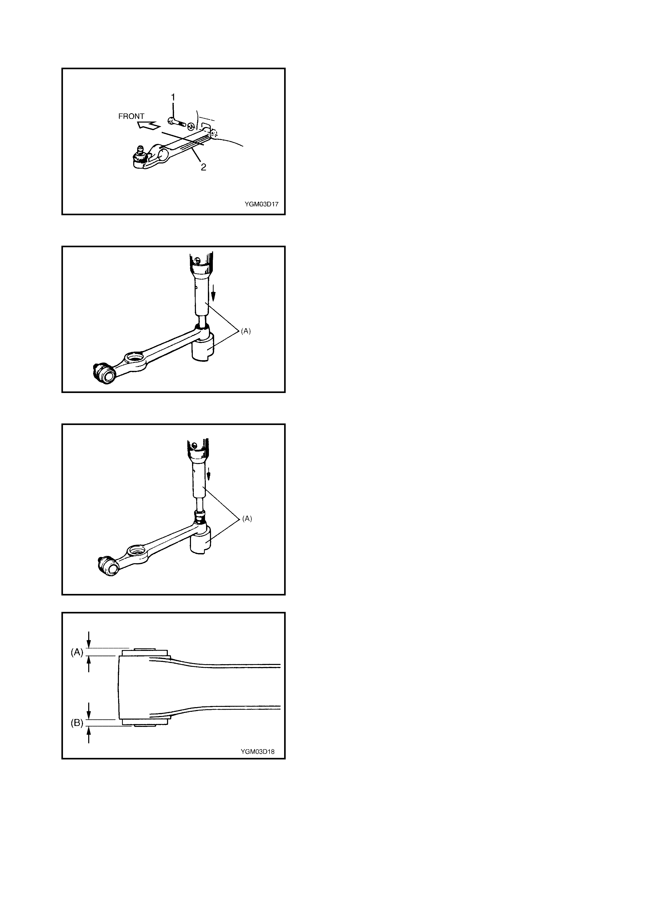
3. Remove the suspens ion control arm bolt (1).
4. Remove the suspens ion control arm (2).
DISASSEMBLY
1. Remov e bushing.
Place the suspension control ar m o nto the flat surface
side of the special tool and push out bushing with
special tool 09943-77910 (A) and hydraulic press as
shown.
ASSEMBLY
1. Press-fit the bushing using special tool 09943-77910
(A) and a h ydraulic press.
CAUTION: Always use new bushing.
NOTE:
•Before installing bushing, apply soapy water around
the outer surf ace to ease installation.
2. Press-fit the bushing so th at dimensions (A) and (B ) in
the f igure are equal.
INSTALLATION
1. Install the body side of the suspension control arm first
but only loosely fit the control arm bolt (1) at this step.
2. Install the suspension control arm ball joint to the
steering knuckle. Align the ball stud groove with the
steering knuckle bolt hole then install the ball joint bolt
(1) from the direction as shown in figure.
Tighten the suspension arm ball joint bolt (1) to
specified torque.
3. Install the stabiliser bar, refer to 2.2, STABILISER BAR
AND/OR BUSHINGS in this Section.
4. Lower the hoist and with the vehicle in a no-load condi-
tion, tighten the control arm bolt to specified torque at
the position where the control arm is installed at angle
(A) as shown below.
5. Confirm wheel alignment, refer to Section 3A FRONT
END ALIGNMENT.
4. REQUIRED SERVICE MATERIAL
SUSPENSION ARM BALL JOI NT BOLT (a)
TO RQUE SPECIF ICATION 60 Nm
CONTROL ARM ANGLE (A) 15° ± 5°
CONTROL ARM BOLT (b)
TORQUE SPECIFICATION 60 Nm
Material R ecommended produ c tUse
Lithium grease Lithium grease •Strut b earing
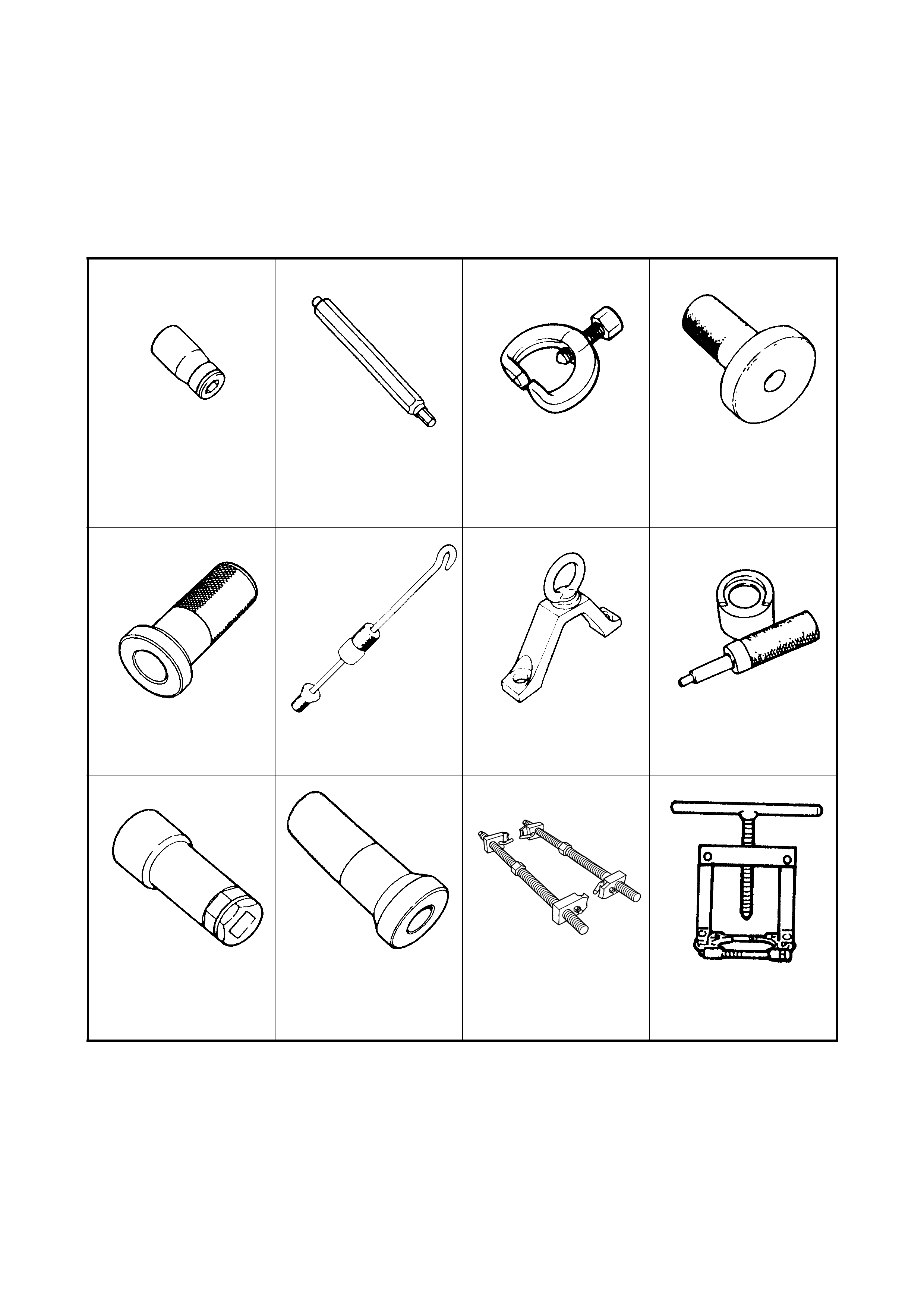
5. SPECIAL TOOLS
NOTE: Refer to Section 0A GENERAL INFORMATION – 7.0 CONSOLIDATED TOOLS for a detailed list of
special tools and the local equivalent if one is available.
09900-00411 09900-00414 09913-65210 09913-75520
Hexagon wrench socket Hexagon wrench bit 6
mm Tie rod end remover Bearing installer
09913-75810 09942-15510 09943-17912 09943-77910
Beari ng installer Sliding ham m er Front wheel hub remove r Bush ing remover
09945-26010 09913-75510 09940-71431 09913-65810
Socket wrench 17 mm Bea ring installer Spring Compres sor Bearing Pul ler
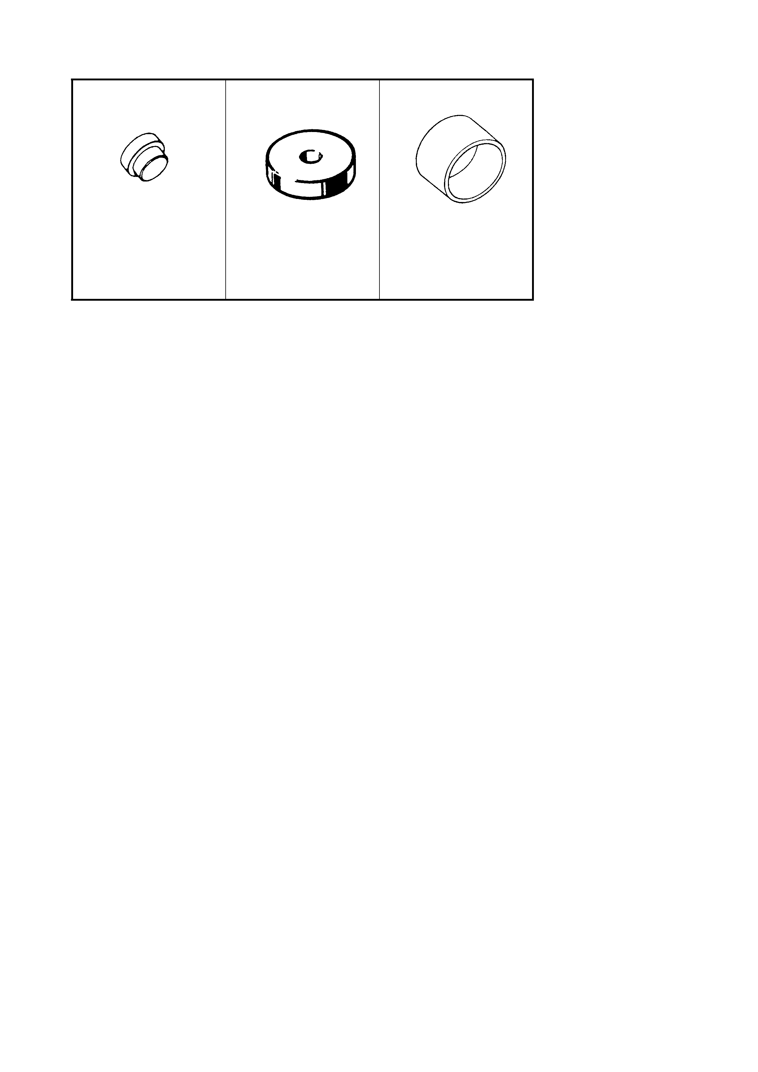
09926-58010 09926-68310 09951-18210
Beari ng puller attach-
ment Bearing Ins tal ler O il seal installer