
SECTION 3E - REAR SUSPENSION
1. GENERAL DESCRIPTION
2. DIAGNOSIS
2.1 REAR SHOCK ABSORBER CHECK
2.2 TRAILING ARM, LATERAL ROD,
REAR AXLE, PEAR AXLE HOUSING
AND COIL SPRING CHECK
2.3 BUMP STOPPER/SPRING
UPPER SEAT CHECK
2.4 REAR SUSPENSION FASTENERS
2.5 WHEEL DISC, NUT AND
BEARING CHECK
3. O N- VEH IC L E SER VICE
3.1 LATERAL ROD
Removal
Installation
3.2 REAR SHOCK ABSORBER
Removal
Installation
3.3 COIL SPRING
Removal
Installation
3.4 BUMP STOPPER
Removal
Installation
3.5 SPRING UPPER SEAT
Removal
Installation
3.6 TRAILING ARM
Removal
Installation
3.7 REAR AXLE SHAFT AND
WHEEL BEARING
Removal
Installation
3.8 REAR AXLE SHAFT OIL SEAL
Removal
Installation
3.9 REAR AXLE HOUSING
Removal
Installation
4. REQUIRED SERVICE MATERIAL
5. SPECIAL TOOLS
NOTE:
• All suspension fasteners are important attaching parts that could affect the performance of
vital parts and system s. They must be replaced with items with the same part number or with
an equivalent part if replacement becomes necessary. Do not use a replacement part of
lesser quality or substitute design. Torque values must be used as specified during reassem-
bly to assure proper retention of the part.
• Never at temp t to heat, q uench o r straigh ten any re ar suspen sion pa rt. Rep lace it with a new
part, or damage may result.
Techline

1. GENERAL DESCRIPTION
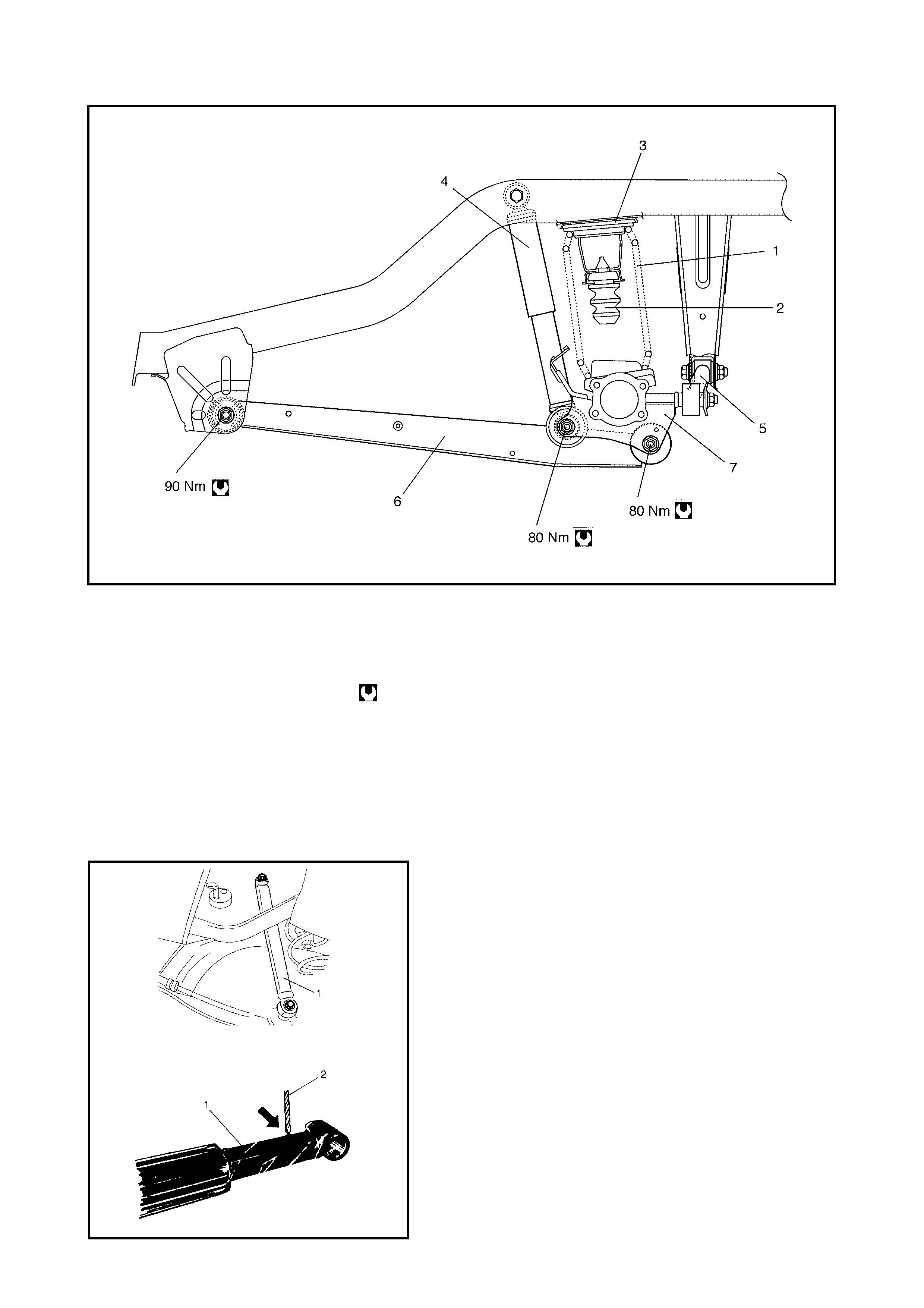
Legend
1. Rear coil spring 8. Wheel Bear ing 14. Wheel bea ring retainer ring
or rear wheel sensor ring
(if equipped with ABS)
2. Rear bump stopp er 9. Brake drum
3. Rear spring upper seat 10. Rear axle shaft
4. Rear shock absorber 11. Breather cap 15. ABS vehicles
5. L a te ral rod 12. Oil seal p ro te c tor 16. Non ABS v e hic les
6. Trailing arm 13. Oil seal Tightening torque
7. Rear axle housing
Legend
2. DIAGNOSIS
2.1 REAR SHOCK ABSORBER CHECK
• Inspect for deformation or damage.
• Inspect bushings for wear or damage.
• Inspect for evidence of oil leakage.
Replace any defective par t.
WARNING: When handling rear shock absorber (1) in
which high-pressure gas is sealed, make sure to
observe the following precautions.
• Do not disassemble it.
• Do not place in fire.
• Do not s tore un de r hot c on di t io ns .
• Before disposal, drill a hole (approximately 3 mm
diameter) (2) where shown by the arrow in the fig-
ure to allow gas and oil to escape .
When drilling (2) wear safety goggles. Alt hough the
gas in the shock absorber is harmless it may
escape rapidly along with metal filings creating a
safety risk.
1. Rear coil spring 5. Lat eral rod
2. Rear bump stopper 6. Tr ailing ar m
3. Rear spring upper seat 7. Rear ax le housing
4. Rear shock absorbe r Tightening torque

2.2 TRAILING ARM, LATERAL ROD, REAR AXLE, REAR AXLE HOUSING AND COIL
SPRING CHECK
• Inspect for cracks, deformation or damage.
• Inspect bushing for damage, wear or breakage.
Replace any defective part.
2.3 BUMP STOPPER/SPRING UPPER SEAT CHECK
• Inspect for cracks, deformation or damage.
Replace any defective part.
2.4 REAR SUSPENSION FASTENERS
Check to ensure that all nuts and bolts are tight. Tighten
any loose nuts and bolts to specified torque, refer to
1. GENERAL DESCRIPTION in this Section.

2.5 WHEEL, NUT AND BEARING CHECK
• Inspect each wheel for den ts, distor t ion and cracks.
A badly damaged wheel must be replaced.
• Check wheel nuts are tight and where necessary,
retighten to specification.
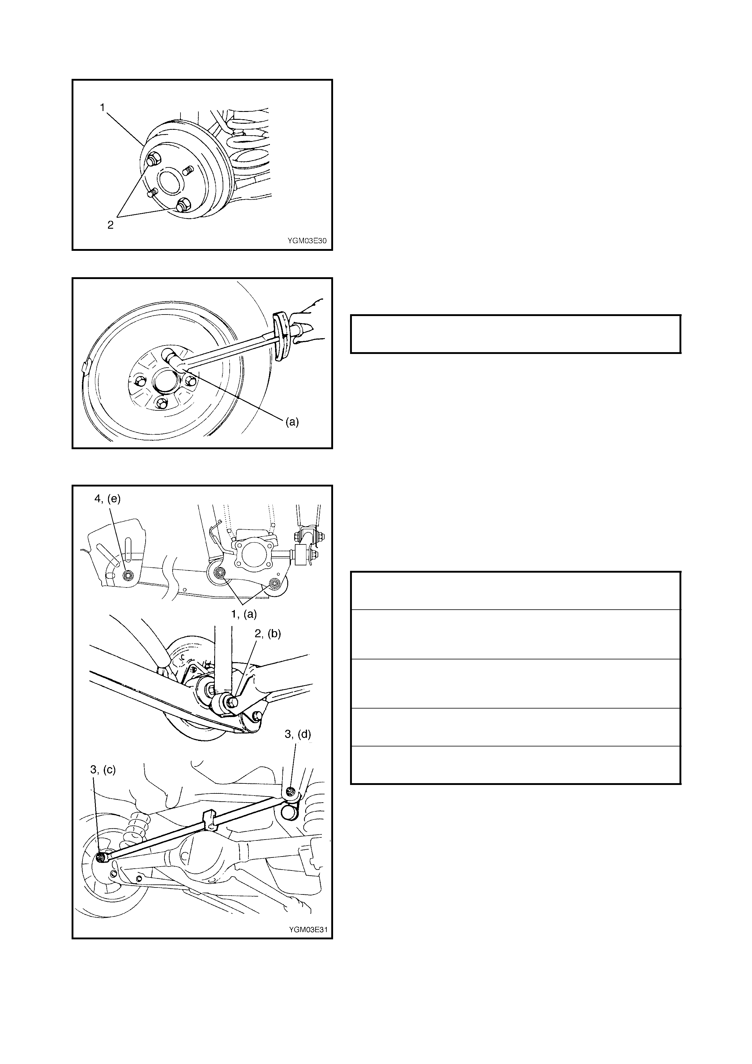
• Check wheel bearings for wear. Apply a dial gauge to
the centre of the axle shaft to measure thrust play.
• When measurement exceeds limit, replace bearing.
• Rotate the wheel by hand to check the wheel bearing
fo r noise and smooth rotation. If it is defective, replace
the bear ing.
3 . ON-VEHICLE SERVICE
3.1 LATERAL ROD
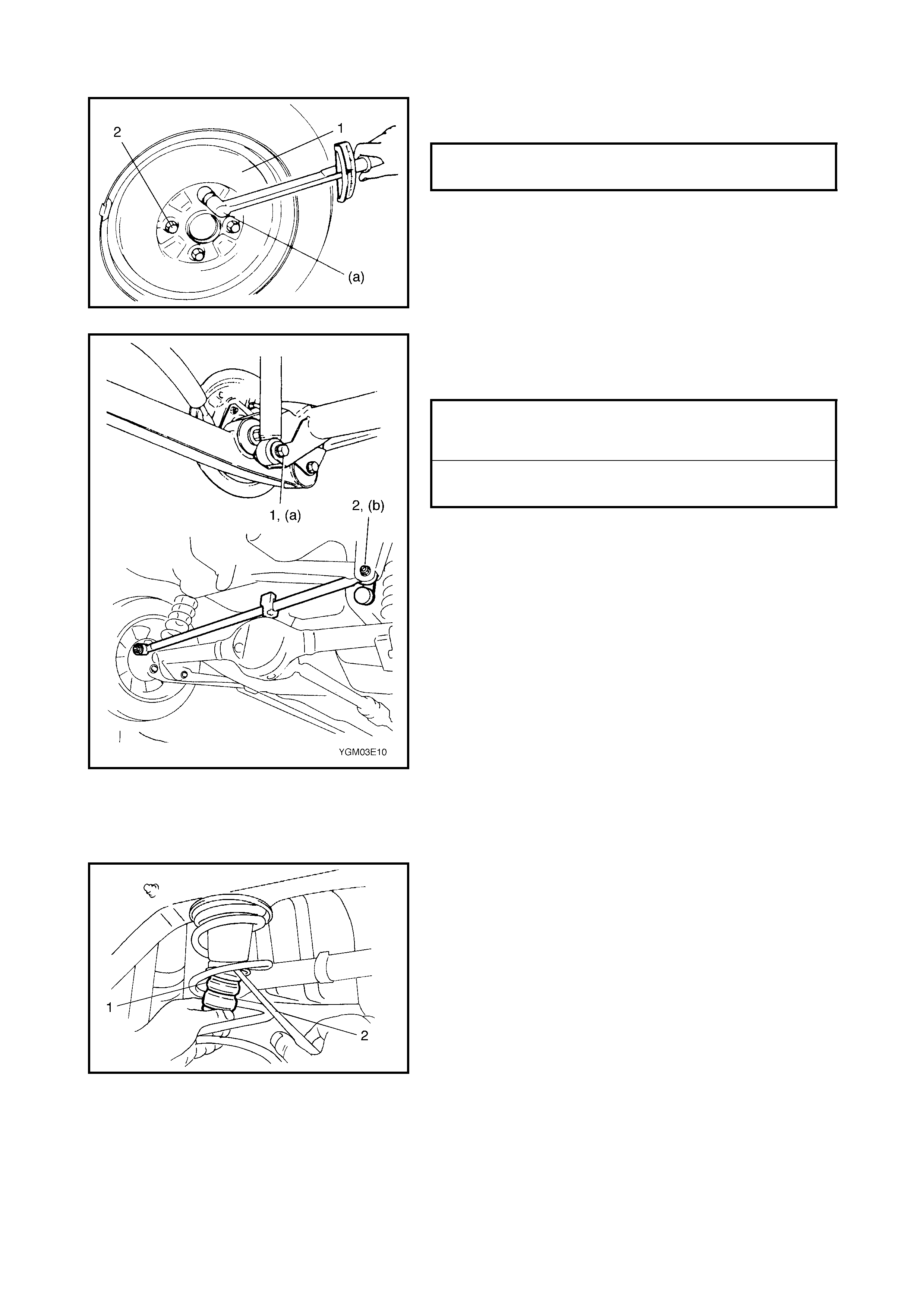
REMOVAL
1. Hoist vehicle.
2. Remove lateral rod nuts (1) and bolt (2).
3. Remov e lateral rod (3).
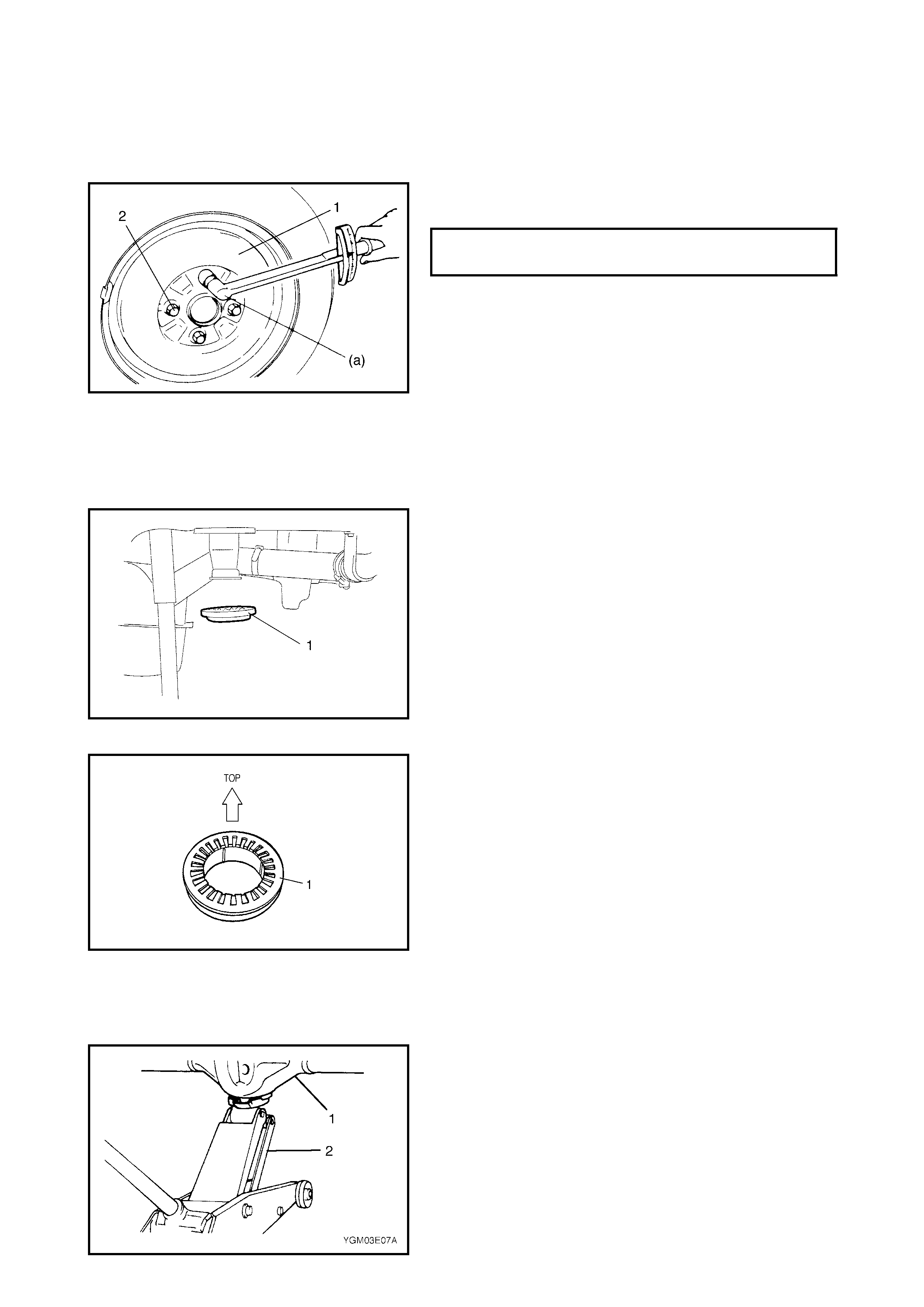
WHEEL NUTS (a)
TORQUE SPECIFICATION 85 Nm
THRUST PLAY LIMIT (a) 0.1 mm
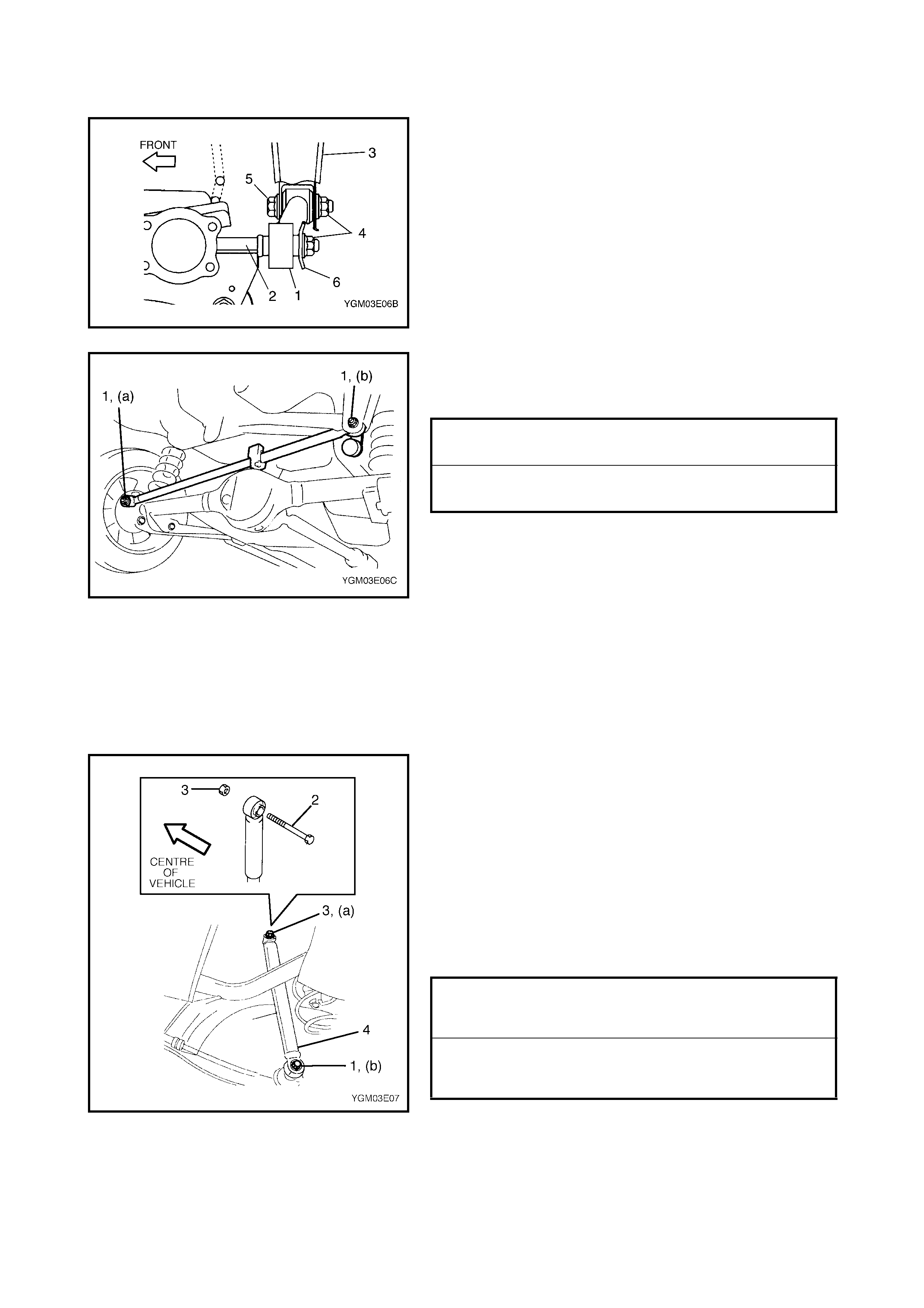
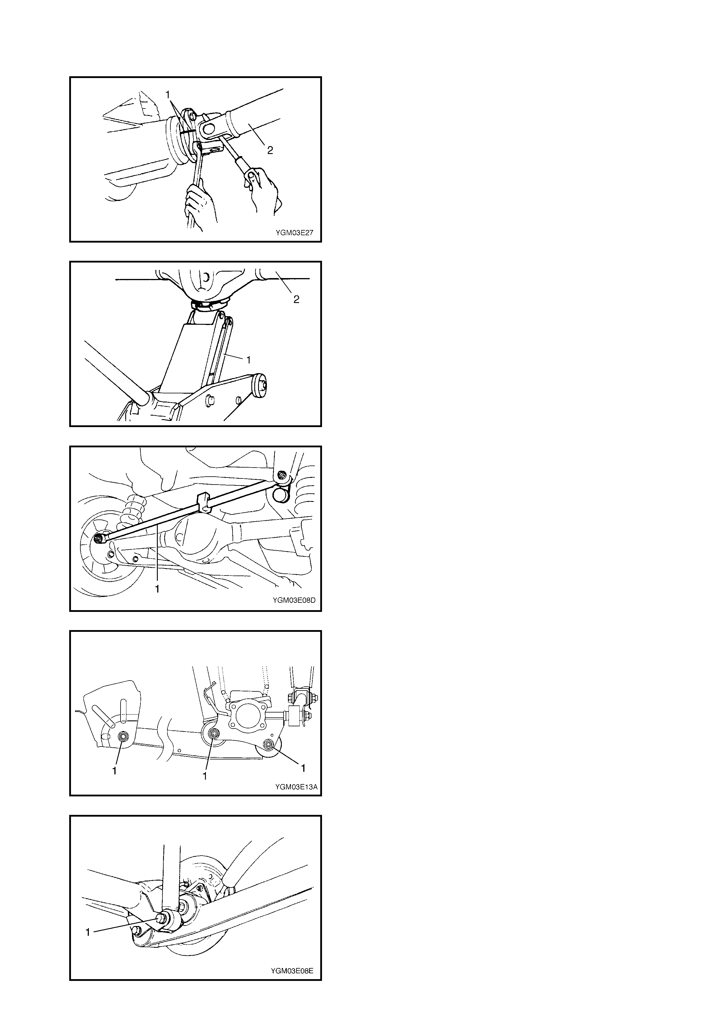
INSTALLATION
1. Install lateral rod (1) to rear axle housing (2) and
vehicle body (3) referring to the figure for correct instal-
lation direction of nuts (4), bolt (5) and washer (6).
Tighten nuts temporarily by hand at this step.
2. Lower hoist.
3. Tighten lateral rod nuts (1) to specified torque. It is rec-
ommended to have the vehicle off the hoist and in a
no-load condition when tightening the lateral rod nuts.
3.2 REAR SHOCK ABSORBER
REMOVAL
1. Hoist vehicle.
2. Support the rear axle housing using a floor jack to
prevent it from dropping when shock absorber is
removed.
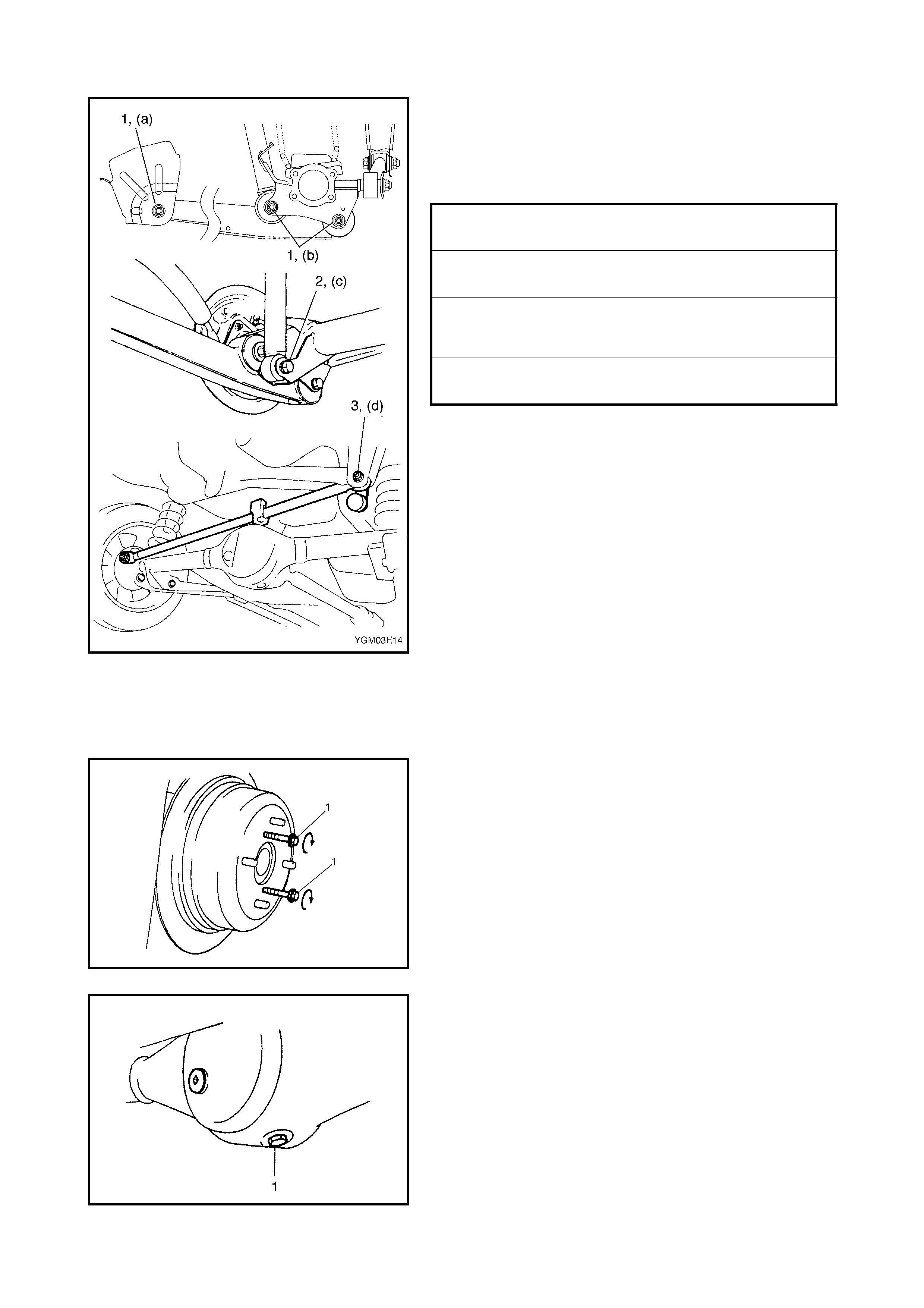
3. Remove lower bolt (1).
4. Remove upper bolt (2) and nut (3). Remove shock
absorber (4).
INSTALLATION
1. Install the shock absorber (4) referring to the figure.
Tighten bolt and nut temporarily by hand at this step .
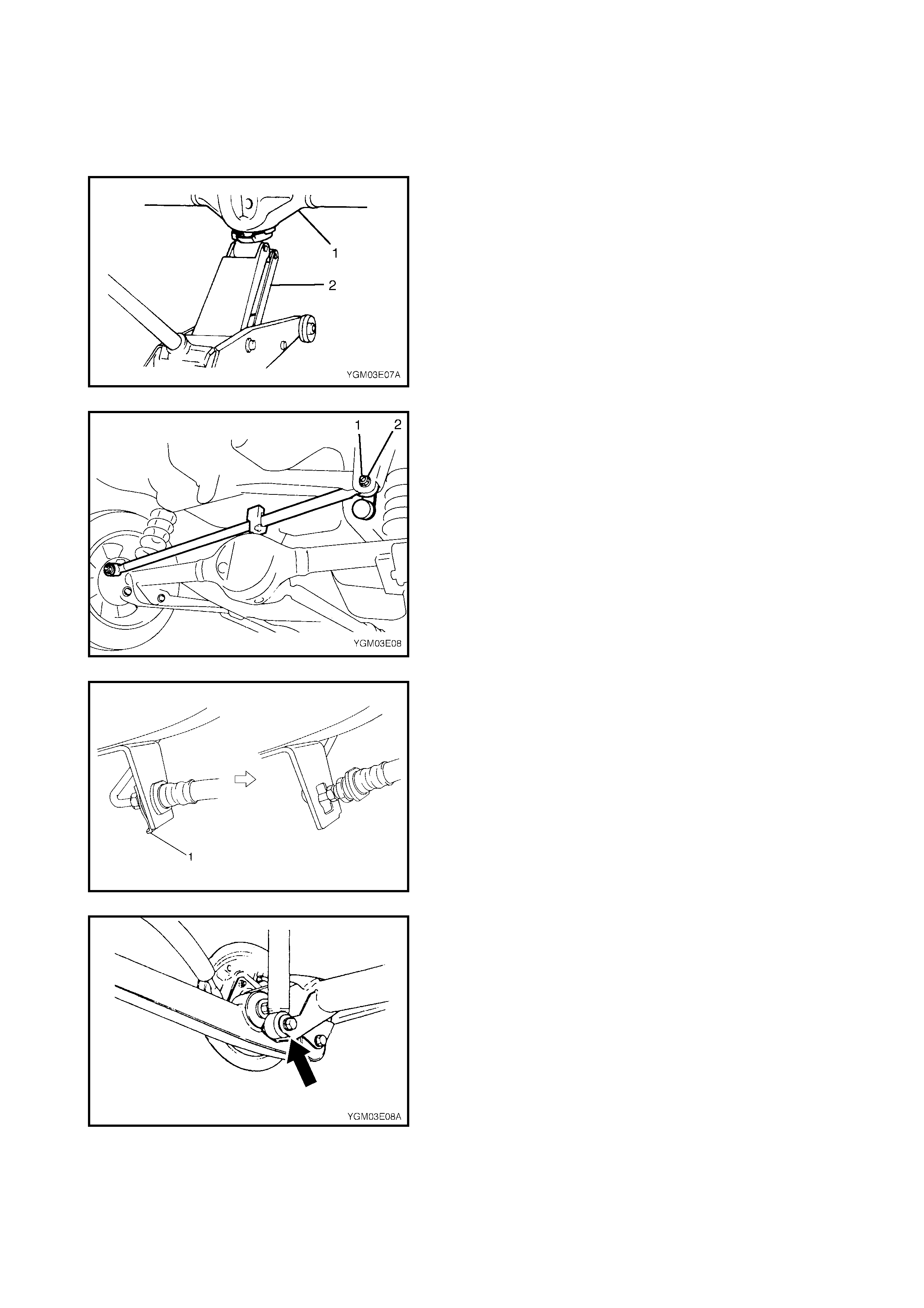
2. Remove the floor jack from the rear axle housing (1)
and lower hoist.
3. With the vehicle in a no-load condition tighten bo lt and
nut to specified torque.
LATERAL ROD LEFT SIDE NUT (a)
TORQUE SPECIFICATION 50 Nm
LATERAL ROD RIGHT NUT (b )
TORQUE SPECIFICATION 65 Nm
REAR SHOCK ABSORBER UPPER
NUT (a)
TORQUE SPECIFICATION 85 Nm
REAR SHOCK ABSORBER LOWER
NUT (b)
TORQUE SPECIFICATION 85 Nm
3.3 COIL SPRING
REMOVAL
1. Hoist vehicle and remove the rear wheel (s).
2. Support the rear axle ho using using a floor jack (2) to
prevent it from dropping when spring is removed.
3. Remove the lateral rod r igh t side bolt (1) and nut (2).
4. Detach lateral rod from the vehicle body.
5. Remove the brake flexible hose E-ring (1).
6. Remove the Lo ad S ensing Pr oportioning Valve (LSPV)
adjusting nut and detach the spring end from the axle
housing (if equipped with LSPV - non ABS vehicles).
7. Detach the shock absorber lower end from the rear
axle housing.
8. Lower the rear axle housing gradually, to the point
wher e t he coil spri ng (2 ) ca n be removed.
CAUTION: Be careful not to let the rear axle housing
down too far as it may damage the flexible brake hose.
9. R e mo ve th e coil spr ing .
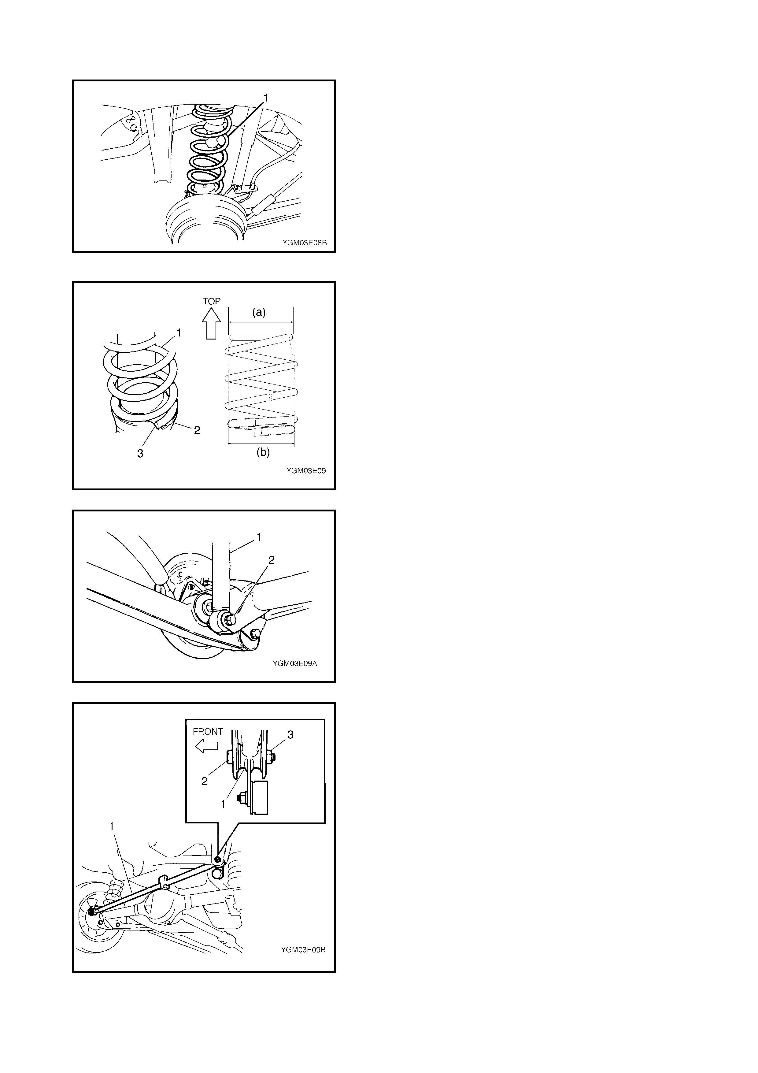
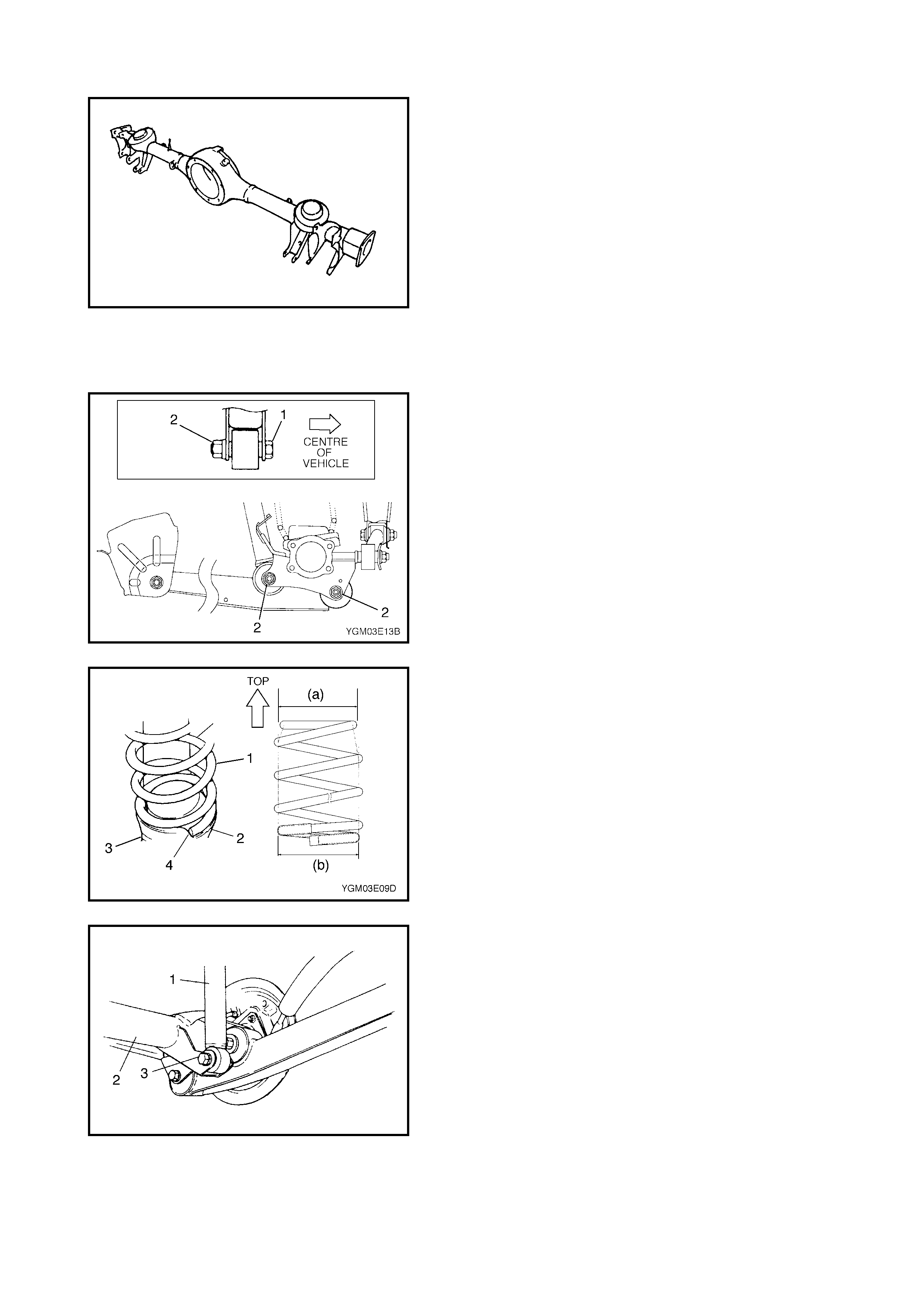
INSTALLATION
1. Install the coi l spring (1) o n the lower spri ng seat (2) of
the rear axle housing and mate the spring open end
with the stepped part (3) of the spring lower seat and
raise the rear axle housing.
NOTE: The upper and lower diameters of the coil spring
are different. Ensure the larger diameter (b) faces down
and the sma ller diameter (a) faces up.
2. Install the shock absorber (1) lo wer end to t he rear axle
housing.
Tighten the shock absorber lower bolt (2) temporarily
by hand at this step.
3. Install the right side o f the lateral rod (1) to the vehicle
body, refer to the figure for correct installation direction
of bolt (2).
Tighten nut (3) temporarily by hand at this step.
4. Remove the floor jack from the rear axle housing.
5. Install the brake f lexible hose E-ring.
6. Install the load sensing proportioning valve (LSPV)
spr ing to th e axle housing. Tight en LSPV ad justing nut
temporar ily at this step (if equipped with LSPV).
7. Install the wheel (1) and tighten wheel nuts (2) to
specified torque.
8. Lower the hoist and with the vehicle in a no-load condi-
tion, tighten the shock absorber lower bolt (1) and the
lateral rod right side nut (2) to specified torque.
9. If equipped with LSPV, check and adjust LSPV spring,
refer to Section 5, 3.8 LSPV ASSEMBLY (IF
EQUIPPED) INSPECTION AND ADJUSTMENT and
perform a fluid pressure test, refer to Section 5, 2.12
FLUID PRESSURE TEST (IF EQUIPPED WITH
LSPV).
3.4 BUMP STOPPER
REMOVAL
1. Hoist vehicle and remove rear wheel.
2. Remove the bump stopper (1) using flat tip rod (2) or
similar.
WHEEL NUTS (a)
TORQUE SPECIFICATION 85 Nm
REAR SHOCK ABSORBER LOWER
BOLT (a)
TORQUE SPECIFICATION 85 Nm
LATERAL ROD RIGHT SIDE NUT (b)
TORQUE SPECIFICATION 65 Nm
INSTALLATION
1. Install bumper stopper.
NOTE: Before installing bushing apply soapy water to its
outside surface to ease installation.
2. Install wheel (1) and tighten wheel nuts (2) to specified
torque.
3.5 SPRING UPPER SEAT
REMOVAL
1. Remove the coil spring. Refer to 3.3 COIL SPRING in
this Section.
2. Remove the spring upper seat (1).
INSTALLATION
1. Install the spring upper seat (1).
NOTE: For correct installation direction of spring upper
seat (1), refer to the figure.
2. Install the coil spring. Refer to 3.3 COIL SPRING in this
Section.
3.6 TRAILING ARM
REMOVAL
1. Hoist vehicle and remove the rear wheel.
2. Support the rear axle housing (1) using a floor jac k (2).
CAUTION: Never apply the floor jack against the lat-
eral rod as it may be deformed.
WHEEL NUTS (a)
TORQUE SPECIFICATION 85 Nm
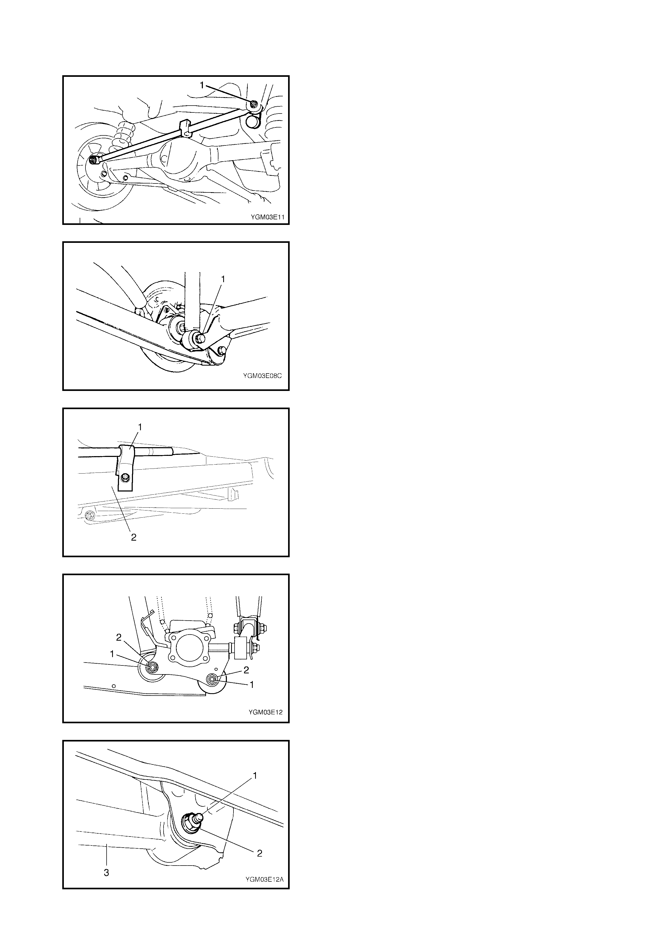
3. Remove the lateral rod right side bolt and nut (1).
4. Remove the right and left side shock absorber lower
bolts (1).
5. Remove the parking brake cable clamp (1) from the
trailing arm (2).
6. Release the wheel speed sensor lead wire clamps
from t he trailin g arm ( if equipped wit h ABS).
7. Remov e the trailing arm rear bolts (1) and nuts (2).
8. Remov e the trailing arm front bolt (1) and nuts (2), then
remove the trailing arm (3).
INSTALLATION
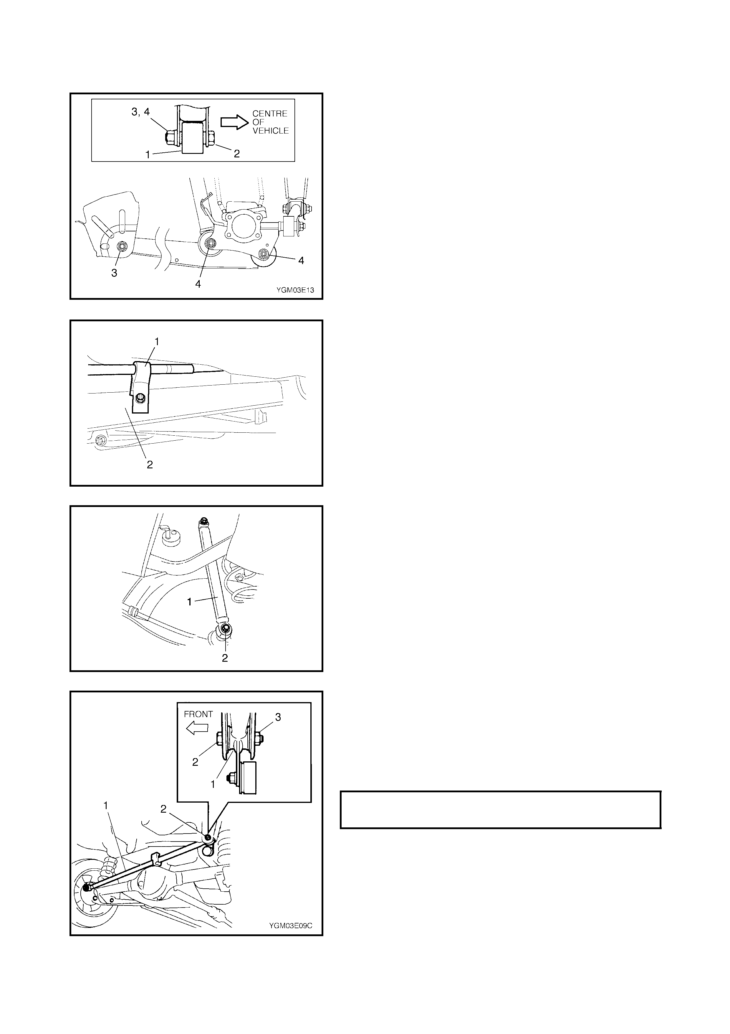
1. Install the trailing arm (1) to the vehicle body and the
rear axle housing, referring to the figure for correct
installation direction of bolts (2).
Tighten the front nut (3) and rear nuts (4) temporarily
by hand at this step.
2. Install the par king brake cable clamp (1) to the trailing
arm (2).
3. Clamp the wheel speed sen sor lead wire to the trailing
arm securely (if equipped with ABS).
4. Install the shock absorber (1) lo wer end to t he rear axle
housing.
Tighten the shock absorber lower bolt (2) temporarily
by hand at this step.
5. Install the lateral rod (1) to the vehicle body, ref e r to the
figure for c orrect installation direction of bolt (2).
Tighten nut (3) temporarily by hand at this step.
6. Remove the floor jack from the rear axle housing.
7. Install the wheel and tighten the wheel nuts to specified
torque.
8. Lower hoist.
WHEEL NUTS
TIGHTENING TORQUE 85 Nm
9. Tighten the front and rear trailing arm nuts (1), the
shock absorber lower bolts (2) and the lateral rod right
side nut (3) to specified torque.
NOTE: When tightening these nuts, be sure that the vehicle
is off the hoist and in a no-load condition.
3.7 REAR AXLE SHAFT AND WHEEL BEARING
REMOVAL
1. Hoist vehicle and remove the rear wheel.
2. Remove the rear brake drum using two 8mm bolts (1)
as shown in figure. For details refer to Section 5, 3.3
REAR BRAKE, BRAKE DRUM REMOVAL.
3. Drain the gear oil from the rear axle housing by
loosening the drain plug (1).
4. Remove the brake shoes, refer to BRAKE SHOE
REMOVAL in Section 5, 3.3 REAR BRAKE.
FRONT TRAILING ARM NUT (a)
TORQUE SPECIFICATION 90 Nm
REAR TRAILING ARM NUTS (b)
TORQUE SPECIFICATION 80 Nm
REAR SHOCK ABSORBER LOWER
BOLTS (c)
TORQUE SPECIFICATION 85 Nm
LATERAL ROD RIGHT SIDE NUT (d)
TORQUE SPECIFICATION 65 Nm
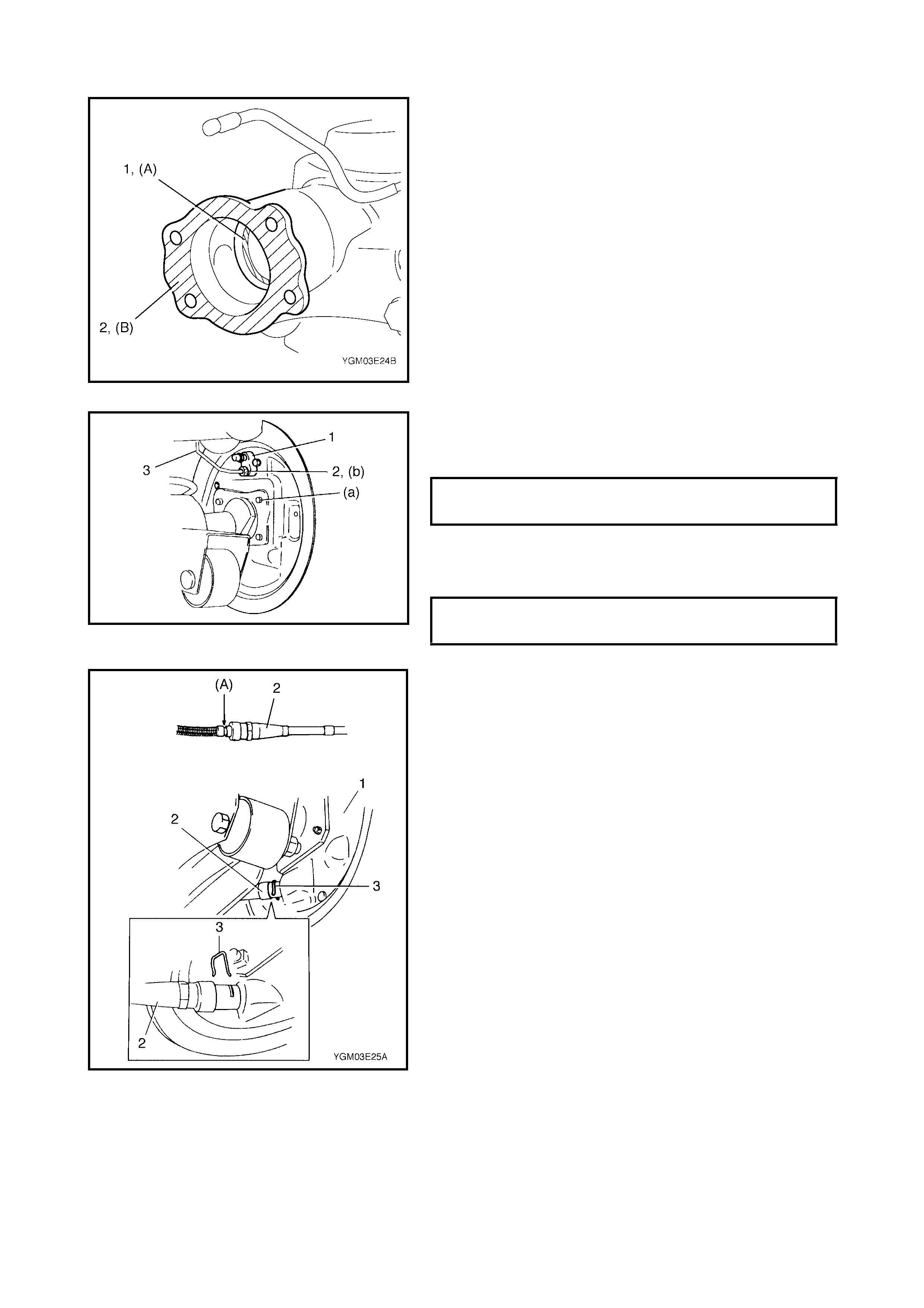
5. Remove parking brake cable from brake back plate.
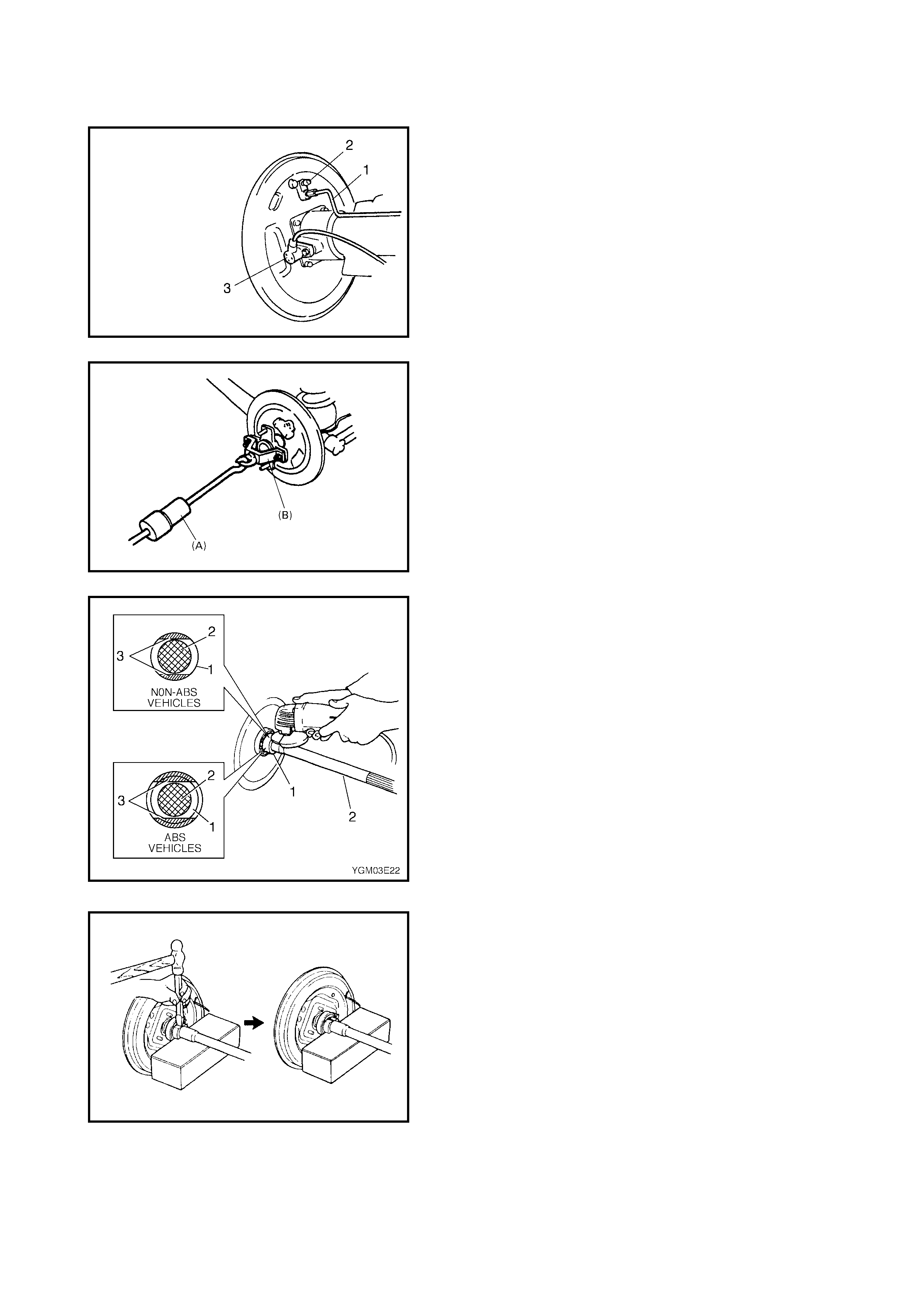
6. Disconnect the brake pipe (1) from the wheel cylinder
and put the wheel cylinder bleeder plug cap (2) onto
the pipe to prevent fluid from spilling.
7. Remove the wheel speed sensor (3) from the axle
housing (if equipped with ABS).
8. Remove the brake back plate bolts from the axle
housing.
9. Using special tools 09942-15511 (A) and 09943-17912
(B), draw out axle shaft with brake back plate.
10. To remove the retainer ring (1) from the axle shaft (2),
grind (3) on either side of the bearing retainer ring as
shown in figure until it becomes thin.
CAUTION: Take care not to grind completely through
the retainer ring an d damag e the axle shaft.
11. With a cold chisel, break through the thin section of the
retainer ring and remove as shown in figure.
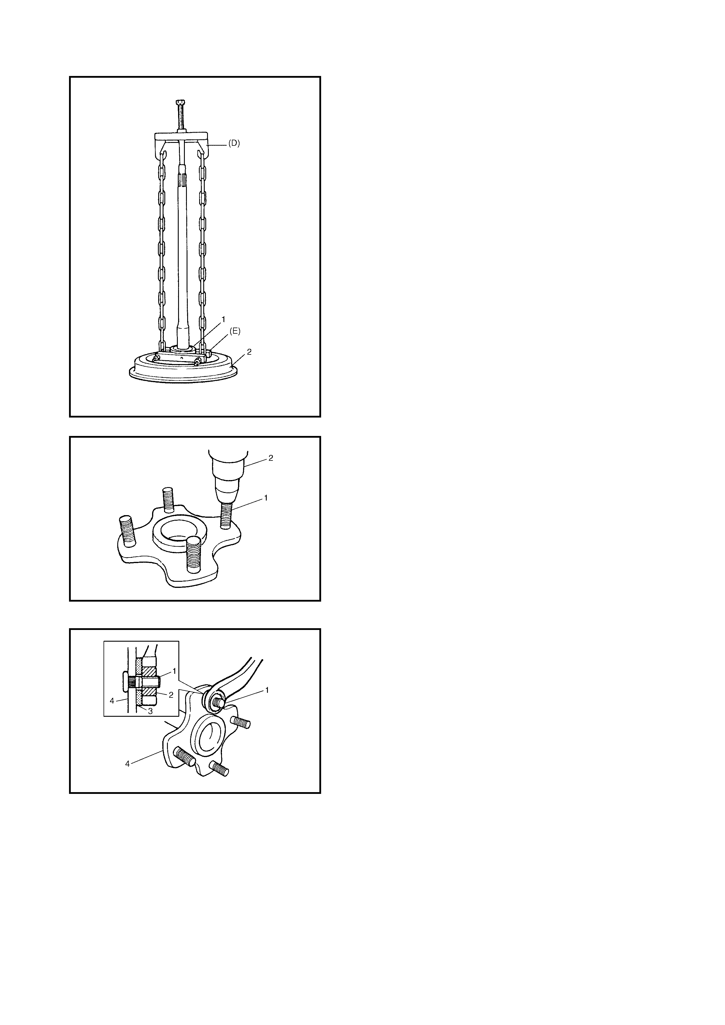
12. Using special tools 09927-18411 (D) and 09921-57810
(E), remove bearing (1) from shaft then remove brake
back plate (2) and wheel bear ing spac er.
13. Remove the stud bolts (1) using a hyd raulic press (2).
INSTALLATION
Install removed parts in reverse order of removal, noting
the following points.
1. Align the serrations on the new stud bolts (1) and the
flange (4), then pull the new stud bolts and washers (3)
into position using a tightening nut (2) as shown in
figure.
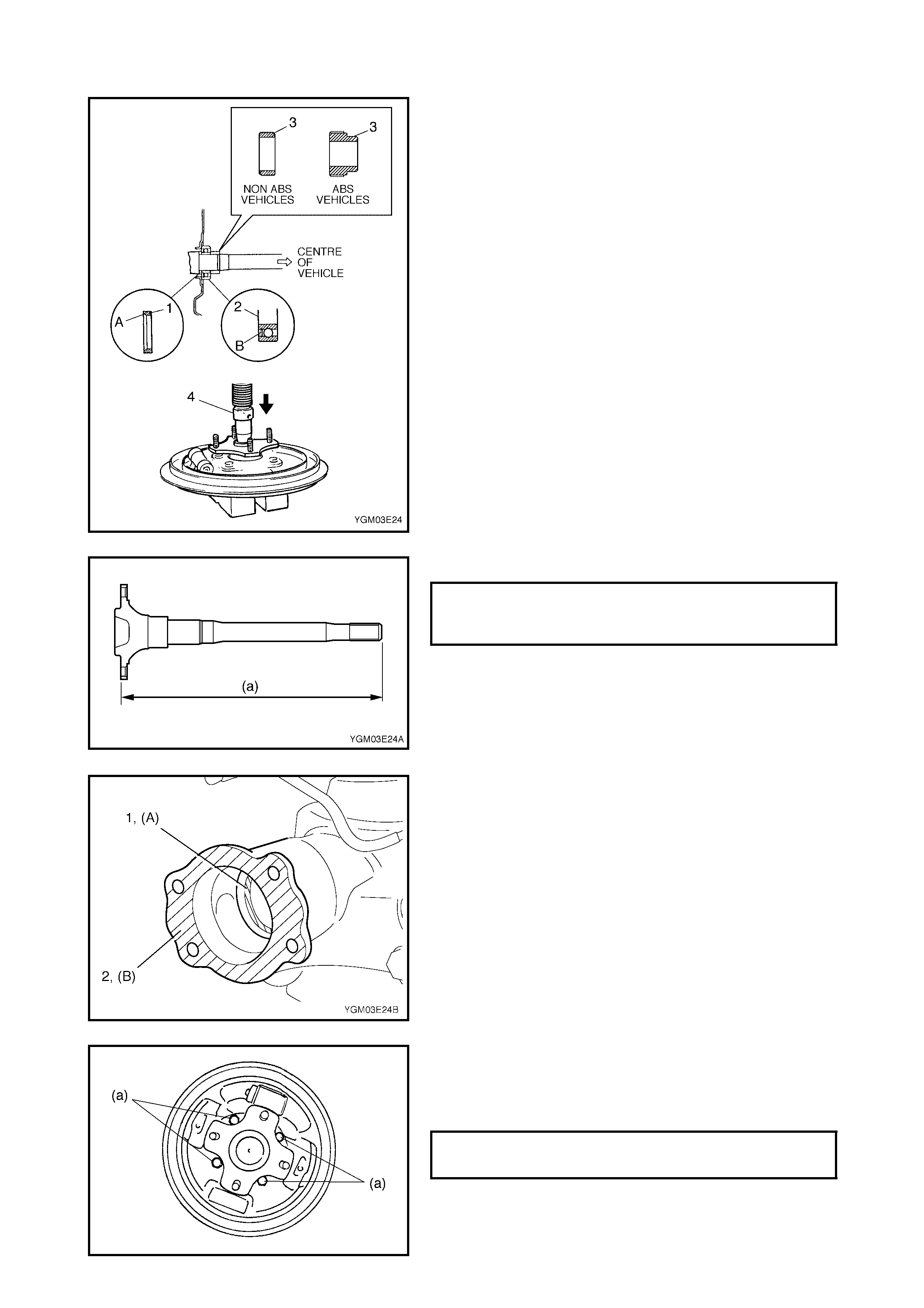
2. Install the new wheel bearing spacer (1) with the
tapered side of its inner diameter facing outwards
(toward the brake drum side).
3. Press fit the new bearing (2) and retainer ring (3) in
order using a hydrauli c press (4).
NOTE:
•Install the wheel bearing with its sealed side facing out-
wards (toward the brake drum side).
•Take care not to cause any damage to the outside of
the retainer ring.
4. Inspect the axle shaft length.
5. Appl y grease to the axle shaft oil s eal lip (1) as s hown
in figure.
(A): Lithium Grease
6. Apply sealant to the mating surfaces of the rear axle
housing (2 ) and the brake back plate.
NOTE: Ens ure any old seal ant is removed before applying
new sealant.
(B): Sealant - Sealing compound 366E
7. Install the rear axle shaft to the rear a xle housing and
tighten the brake back plate bolts to specified torque.
NOTE: When installing the rear axle shaft, be careful not to
damage the oil seal lip in the axle housing.
REAR AXLE SHAFT LENTH (a)
LEFT SIDE
RIGHT SIDE 791.0 mm
672.0 mm
BRAKE BACK PLATE BOLTS (a)
TORQUE SPECIFICATION 23 Nm

8. Connect the brake pipe to the wheel cylinder and
tighten brake pipe flare nut to specified torque.
9. Apply watertight sealant where the brake back plate
and the handbrake cable make contact. Run the
parking brake cable (1) through the brake back plate
(2) and secure it with clip (3).
(A): Sealant - Sealing compound 366E
CAUTION: Check to ensure that the clip is in good
condition before installation. Replace it if it is
deformed or broken.
10. Install the wheel speed sensor (if equipped with ABS).
11. Install the brake shoes, refer to Section 5, 3.3 REAR
BRAKE, BRAKE SHOE INSTALLATION.
12. Install the brake drum. For details refer to Section 5,
3.3 REAR BRAKE, BRAKE DRUM INSTALLATION.
13. Tighten the oil drain plug to specified torque and refill
the rear axle (differential) housing with new specified
gear oil then tighten filler plug to specified torque. Refer
to Section 7F, REAR DIFFERENTIAL.
14. Install the wheel and tighten the wheel nuts to specified
torque.
15. Fill brake reservoir with brake fluid and bleed brake
system. (For bleeding operation refer to Section 5,
3.1 AIR BLEEDING OF BRAKES.
16. Upon completion of all jobs, pull parking brake lever
with a load of approximately 200 Nm (20 kg), three to
five times to obtain correct drum-to-shoe clearance.
Adjust parking brake cable (for adjustment, refer to
Section 5, 2.10 PARKING BRAKE INSPECTION AND
ADJUSTMENT).
17. Check to ensure that the brake drum is free from
dragging and proper braking is obtained.
18. Perform brake test (foot brake and parking brake).
(For brake test, refer to Section 5 BRAKES.)
19. Check each installed part for oil leakage.
3.8 REAR AXLE SHAFT OIL SEAL
REMOVAL
1. Remove rear axle shaft. For details, refer to Steps 1 to
8, 3.7 REAR AXLE SHAFT AND WHEEL BEARING,
REMOVAL in this Section.
BRAKE PIPE FLARE NUT (a)
TORQUE SPECIFICATION 16 Nm
WHEEL NUTS
TIGHTENING TORQUE 85 Nm
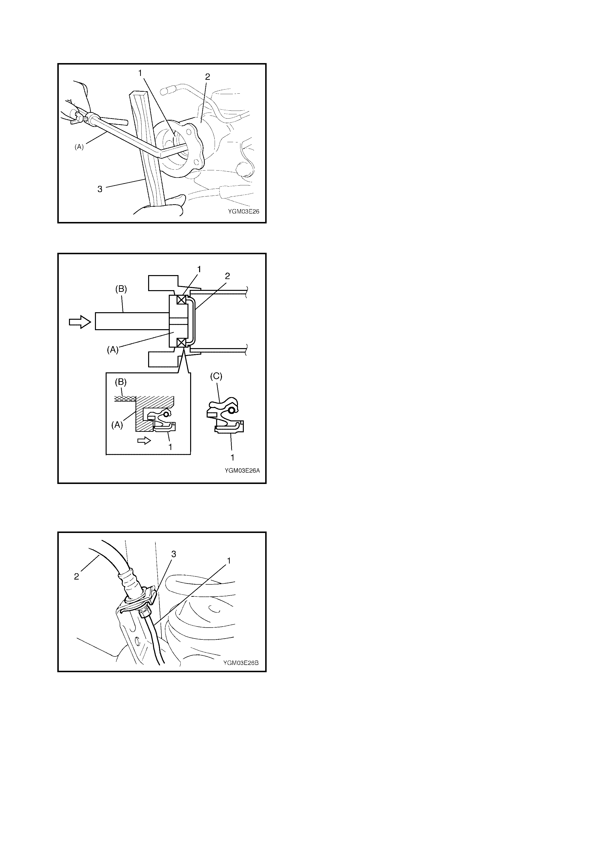
1. Remove the axle shaft oil seal (1) from the axle
housing (2) using a wooden block (3) and special tool
09913-50121 (A).
INSTALLATION
1. Using special tools, 09944-67010 (A) and 09924-
74510 (B), press fit the oil seal (1) until it contacts the
oil seal protector (2) in the axle housing.
NOTE:
• Ensure that the oil seal is not angled as it is installed.
• Ensure that the oil seal is installed in the correct direc-
tion (refer to the figure).
• Apply grease (C) to the inside surface of the seal as
shown in figure.
(C): Lithium Grease
2. To complete the installation, refer to Steps 5 to 17,
3.7 REAR AXLE SHAFT AND WHEEL BEARING in
this Section.
3.9 REAR AXLE HOUSING
REMOVAL
1. Hoist vehicle and remove the rear wheels.
2. If required remove the rear axle shafts (right and left),
refer to Steps 1 to 9, 3.7 REAR AXLE SHAFT AND
WHEEL BEARING in this Section.
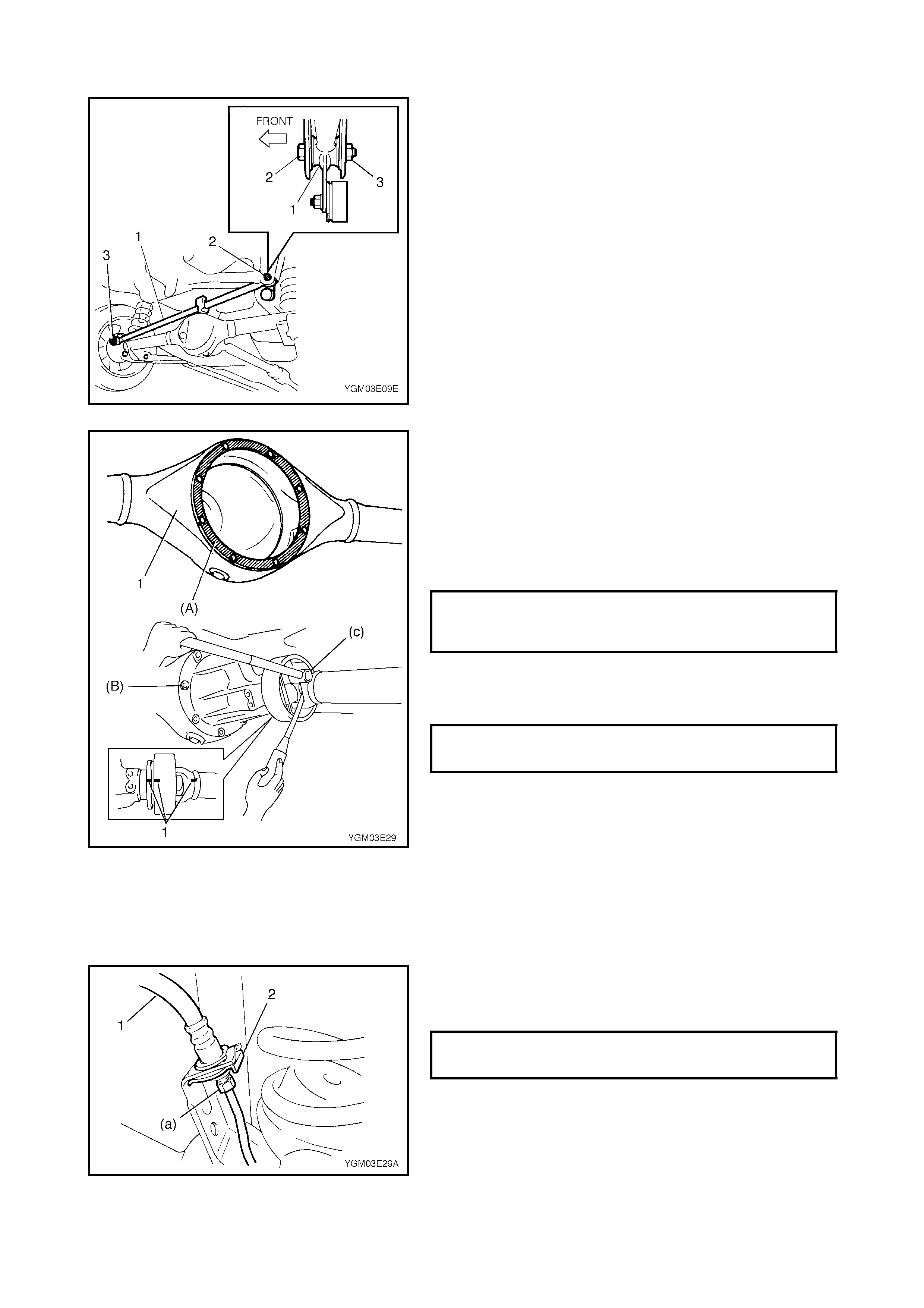
3. Disconn ect the brake pipes (1) (right and l eft) from the
fle xible hoses (2) and remov e E-rings (3).
4. Release the wheel speed sensor and wiring clamps
from the axle housing (if equipped with ABS).
5. Remove the LSPV adjusting nut and detach spring end
from the rear axle housing (if equipped with LSPV).
6. Before removing the propeller shaft, make matching
alignment marks (1) on the joint flange and the
propeller shaft (2) as shown.
Remove the propeller shaft.
7. If required, remove the differential carrier assembly,
refer to Section 7F REAR DIFFERENTIAL.
8. The following steps require that the rear axle housing is
suppo rted us ing a floor jack (1) under the axle hou sing
(2).
9. Remov e the lateral rod (1).
10. Loosen the front and rear mounting nuts (1) of the
trailing arm but don’t remove the bolts.
11. Remove the left and right shock absorber lower
mounting bol ts (1).
12. Lower the floor jack until the tension on the rear sus-
pension coil spring is loosened slightly, then remove
the rear mount bolts from the trailing arms (left and
right).
13. Lower the rear axle housing gradually and remove the
coil spring (left and right sides).
14. Remove the axle housing.
INSTALLATION
Install removed parts in reverse order of removal, noting
the following.
1. Place the rear axle housing on the floor jack. Install the
rear trailing arm bolts (1) (right & left) in the correct
direction as shown in figure and tighten nuts (2) tempo-
rarily by hand.
2. Install the coil springs (1) (right & left) on the spring
seat (2) of the rear axle housing (3) and mate the
spr ing o pen end with the steppe d part (4) of the spri ng
lower seat then raise the axle housing.
NOTE: The upper and lower diameters of the coil spring
are different. Ensure the larger diameter (b) faces down
and the sma ller diameter (a) faces up.
3. Install the shock absorber (1) (right and left) to the rear
axle housing (2) and install the bolts in the correct
direction as shown in figure. Tighten the shock
absorber lower bolts (3) (right and left) temporarily by
hand at this step.
4. Install the lateral rod (1) and install the bolt (2) in the
correct direction as shown in the figure. Tighten the
nuts (3) temporarily by hand at this stage.
5. If removed, clean mating surfaces of the axle housing
(1) and the differential carrier and apply sealant to the
housing side.
(A): Sealant Three Bond No. 1215
6. Apply sealant to the carrier bolts and tighten the carrier
bolts to the specified torque
(B): Sealant Three Bond No. 1215.
7. Install the propeller shaft to the joint flange, aligning
matching marks (1) and tighten the flange bolts to
specified torque.
8. Install the load sensing proportioning valve (LSPV)
spr ing to rear axle housing.
Tighten the LSPV adjust nut temporarily at this step. (if
equipped with LSPV).
9. Remov e the floor jack from the axle housing.
10. Connect the brake flexible hoses (1) (right and left) to
the bracket on the axle housing and secure it with E-
r ings (2).
REAR DIFFERENTIAL CARRIER
BOLTS (b)
TORQUE SPECIFICATION 23 Nm
COMPANION FLANGE BOLTS (c)
TORQUE SPECIFICATION 23 Nm
BRAKE PIPE FLARE NUT (a)
TORQUE SPECIFICATION 16 Nm
11. If removed, apply grease to the rear axle shaft oil seal
lip (1) (right and left) as shown in the figure.
(A): Lithium Grease
12. Clean the mating surface (2) (left and right) of the rear
axle housing and the brake pack plate and apply
sealant as shown in the figure.
(B): Sealant - Sealing compound 366E
13. Install the rear axle shaft (right & left) to the rear axle
housing and tighten the brake back plate bolts to
specified torque.
14. Connect the brake pipes (3) to the wheel cylinders (1)
(right & left) and tighten the brake pipe flare nuts (2) to
specified torque.
15. Apply watertight sealant where the brake back plate (1)
and the parking brake cable make contact.
(A): Sealant - Sealing compound 366E
NOTE: Check to ensure that the clip is in good condition
before installing it. If it is deformed or broken, replace.
16. Install the parking brake cable clamps to the trailing
arm.
17. Install the wheel speed sensors (right and left) and
clamp wire securely (if equipped with ABS).
18. Install the brake shoes (right and left), refer to Section 5,
3.3 REAR BRAKE, BRAKE SHOE INSTALLATION.
BRAKE BACK PLATE BOLTS (a)
TORQUE SPECIFICATION 23 Nm
BRAKE PIPE FLARE NUTS (b)
TORQUE SPECIFICATIONS 16 Nm
19. Install the brake drums (1) (right and left) after making
sure that the inside of the brake drum and the brake
shoes are free from dirt and oil. Tighten wheel nuts (2)
temporarily by hand.
20. Fill the brake reservoir with specified brake fluid and
bleed the brake system, refer to Section 5, 3.1 AIR
BLEEDING OF BRAKE SYSTEM.
21. Refill the differential gear housing with specified gear
oil, refer to Section 7F, REAR DIFFERENTIAL.
22. Install wheels and tighten wheel nuts to specified
torque.
23. Upon completion of all jobs, pull the parking brake lever
with a load of approximately 200 Nm (20 kg), three to
five times to obtain a correct drum-to-shoe clearance.
Adjust the parking brake cable (for adjustment, refer to
Section 5, 2.10 PARKING BRAKE INSPECTION AND
ADJUSTMENT.
24. Lower hoist.
25. Tighten the right and left trailing arm nuts (1) and shock
absorber lower bolts (2) to specified torque.
Tighten the lateral rod nuts (3) to specified torque.
NOTE: When tightening these bolts and nuts, be sure that
the vehicle is off the hoist and in a no-load condition.
26. Check to ensure that the brake drum is free from
dragging and correct braking is obtained.
27. Perform brake test (foot brake and parking brake).,
refer to Section 5 BRAKES.
28. If equipped with LSPV, check and adjust the LSPV
spring, refer to Section 5, 3.8 LSPV ASSEMBLY (IF
EQUIPPED), INSPECTION AND ADJUSTMENT and
2.12 FLUID PRESSURE TEST (IF EQUIPPED WITH
LSPV).
29. Che ck each installed par t for oil leakage.
WHEEL NUTS (a)
TORQUE SPECIFICATION 85 Nm
REAR TRAILING ARM NUTS (a)
TORQUE SPECIFICATION 80 Nm
REAR SHOCK ABSORBER LOWER
BOLTS (b)
TORQUE SPECIFICATIONS 85 Nm
LATERAL ROD AXLE HOUSING SIDE
NUT (c)
TORQUE SPECIFICATION 65 Nm
LATERAL ROD BODY SIDE NUT (d)
TORQUE SPECIFICATION 65 Nm
FRONT TRAILING ARMNUTS (e)
TORQUE SPECIFICATION 90 Nm
4. REQUIRED SERVICE MATERIAL
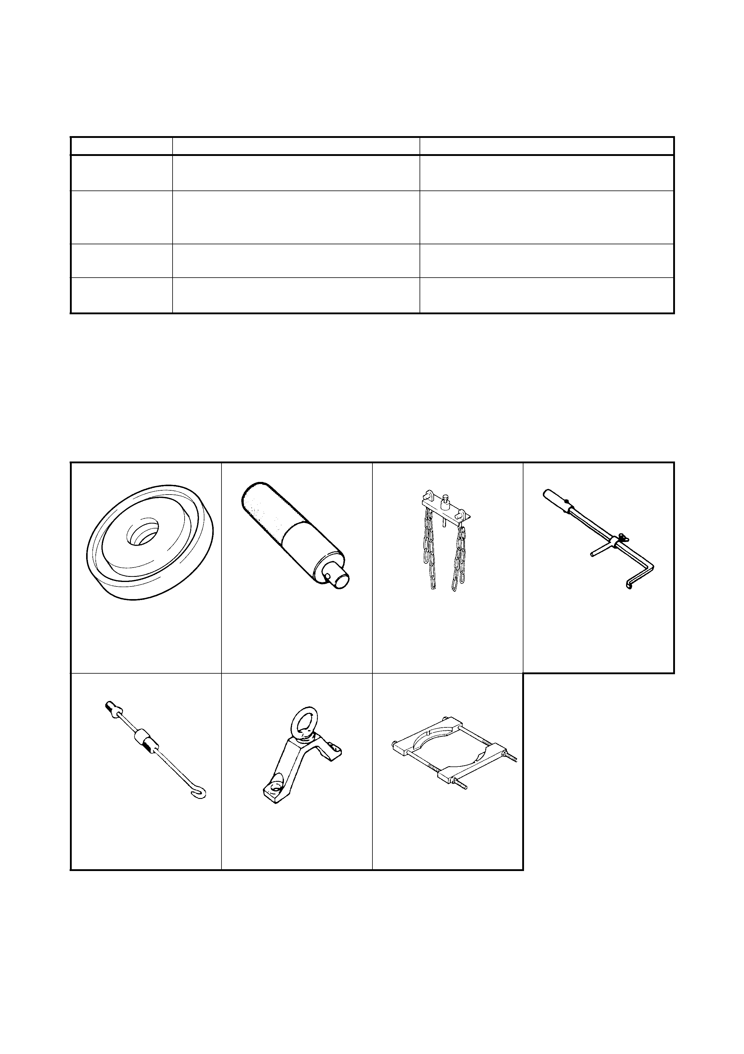
5. SPECIAL TOOLS
NOTE: Refer to Section 0A GENERAL INFORMATION – 7. CONSOLIDATED TOOLS for a detailed list of
special tools and the local equivalent if one is available.
Material
Recommended product
Use
Lithium grease Lithium Grease
• Axle shaft oil seal
• Wheel bearing
Sealant Three Bond No. 1215
• Joint seam of differential carrier and
axle housing
• Differential carrier bolt
Gear oil For gear oil information, refer to Section 7F
REAR DIFFERENT IAL. •Differential gear (Rear axle housing)
W a te r tight
sealant Sealing Com pound 366E •Joint sea m of axle housing and brake
back plate
09944-67010 09924-74510 09927-18411 09913-50121
Oil seal installer Installer attachment Universal puller Oil seal remover
09942-15511 09943-17912 09921-57810
Sliding hammer Brak e drum remover Bearing remov er