
SECTION 3F - WHEELS AND TYRES
1. GENERAL DESCRIPTION
1.1 TYRES
1.2 WHEELS
1.3 REPLACEMENT TYRES
1.4 REPLACEMENT WHEELS
How to Meas ure Wheel Runo ut
Metric Lug Nuts and Wheel Studs
2. DIAGNOSIS
2.1 DIA GNOSIS TA BLE
2.2 BAL ANCING WHEELS
2.3 GENERAL BALANCE
PROCEDURES
Off-vehicle Balancing
On-vehicle Balancing
3. MAINTENANCE AND MINOR
ADJUSTMENTS
3.1 WHEEL MAINTENANCE
Wheel Attaching Studs
3.2 TYRE MAINTENANCE
Tyre P lac ard
Inf l at io n of Ty res
Tyre Rotation
4. ON-VEHICLE SERVICE
4.1 WHEEL
Removal
Installation
4.2 TYRE
Installatio n and Removal
Repair
NOTE:
Wheel fasteners are important attaching parts because they could affect the performance of
vital parts and systems, and/or could result in major repair expenses. They must be replaced
with one of the same part number or with an equivalent part if replacement becomes neces-
sar y. Do no t u se a rep la cemen t p ar t of l esse r qu ali ty o r s ubst itu te desi gn. Torque values mu st
be used as specified during reassembly to assure proper rete ntion of all parts.
There is to be no welding as it may result in extensive damage and weakening of the metal.
1. GENERAL DESCRIPTION
1.1 TYRES
This vehicle is equipped with the following tyre.
Tyre size
175/65R15
The tyre is of tubeless type. The tyre is designed to operate satisfactorily with loads up to the full ra ted load
capacity when inflated to the recommended inflation press ures.
Correct tyre pressures and driving habits have an important influence on tyre life. Heavy cornering, exces-
sivel y rapid acceleration and unnecessary sharp braking increase tyre wear.
1.2 WHEELS
Standard equip men t wheels are aluminium alloy.
Wheel size
15 x 5 1/2 J
1.3 REPLACEMENT TYRES
When repla cement is necessar y, the origi nal equipment t ype tyre should be us ed. Refe r to the Tyre Placard.
Replacement tyres should be of the same size, load range and construction as those originally on the vehicle .
Use of any other size or type tyre may affect ride, handling, speedometer/odometer calibration, vehicle ground
clearance and tyre or snow chain clearance to the body and chassis.
It is recomm end ed t hat new tyres be i nstalled i n pairs on th e sam e ax le. If it is necess ar y t o repl ace only one
tyre, it should be paired with the tyre with the most tread, to equalise braking tractio n.
WARNING: Do not mix different types of tyres on the same vehicle such as radial, bias and bias-
belted tyres except in emergencies, because handling may be seriously affected and may result in
loss of control.
The m etr i c te rm for tyre inflation press ure is the kilo pas cal
(kPa). Tyre pressures are usually printed in both kPa and
psi on t he Ty re Plac ard.
Metr i c tyre gauges are available from tool suppliers.
The accompanying table, converts commonly used inflation
pre ssures from kPa to ps i.
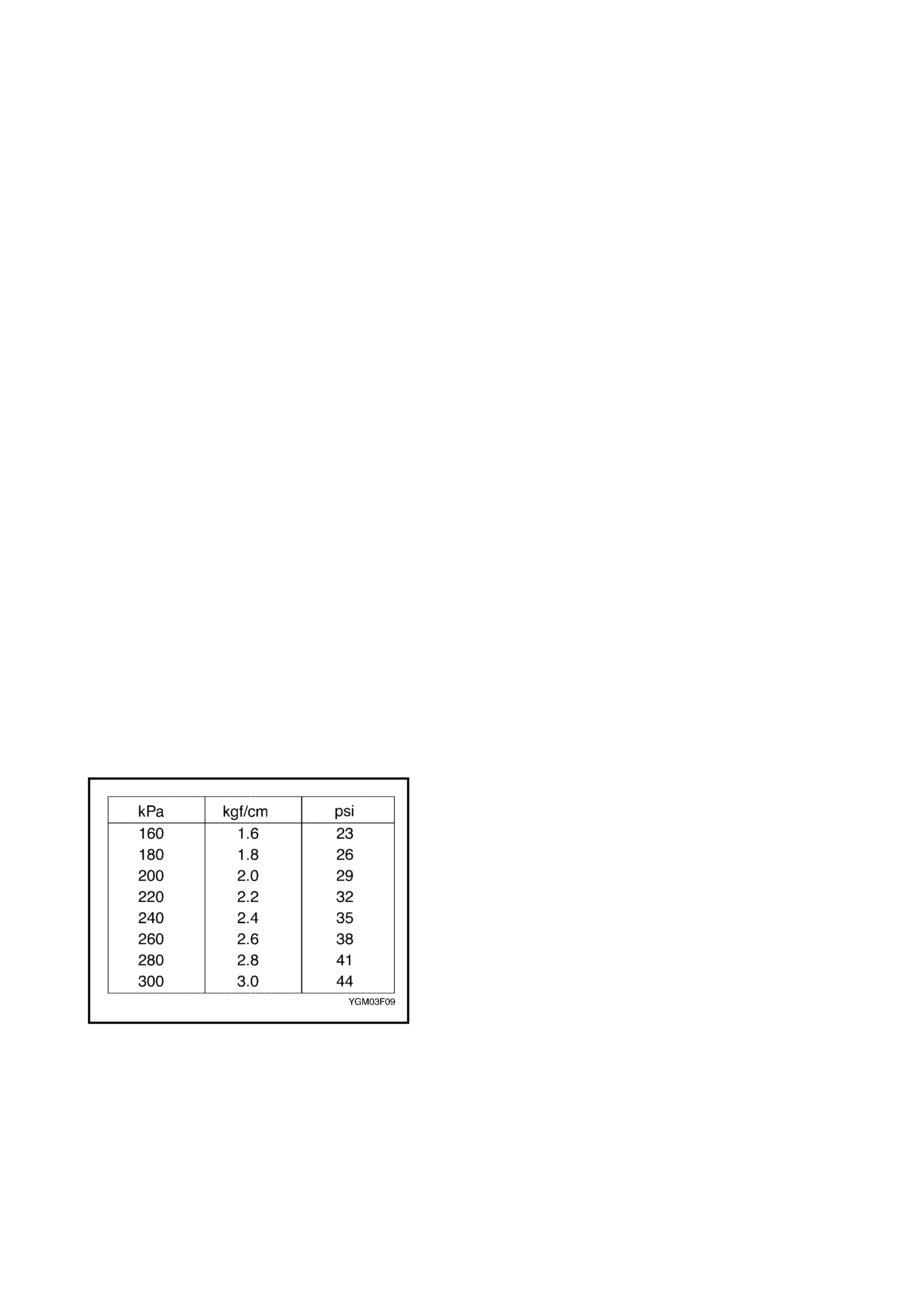
1.4 REPLACEMENT WHEELS
Wheels must be replaced if they are bent, dented, have excessive lateral or radial runout, air leaks through
welds, have e longa ted bolt holes, if lug nuts won’t stay tight, or if they are heavily rusted. Wheel s with greater
runout than shown in the following figure may cause objectionable vibrations.
Replacement wheels must be equival ent t o t he original equipment wheels in load capacity, diameter, rim width
offset a nd moun ting c onfiguration. A wheel of im proper size or t ype may affect wh eel and bearing life, brake
cooling, speedometer/odometer calibration, vehicle ground clearance and tyre clear ance to body and chassis.
HOW TO MEASURE WHEEL RUNOUT
To measure the wheel runout, it is necessary to use an
accurate dial indicator. The tyre may be on or off the wheel.
The wheel should be installed on a wheel balancer for
proper measurement.
Take measurements of both lateral runout (1) and radial
runout (2) on both the inside and outside of the rim flange.
With the dial indicator set in place securely, turn the wheel
slowly one full revolution and record the reading from the
indicator.
When the measured runout exceeds the specification and
correction by the balancer adjustment is impossible,
replace the wheel. If the reading is affected by welding,
paint or scratches, it should be ignored.
METRIC LUG NUTS AND WHEEL STUDS
All models use metric lug nuts and wheel studs.
2. DIAGNOSIS
2.1 DIAGNOSIS TABLE
Refer to Section 3 STEERING, SUSPENSION, WHEELS
AND TYRES.
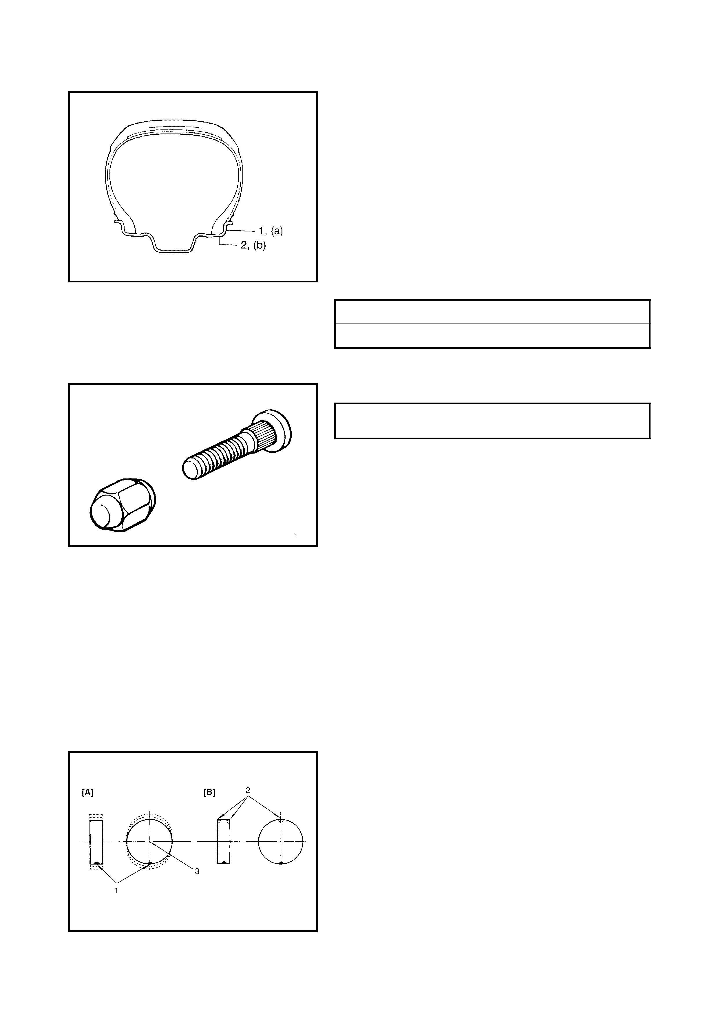
2.2 BALANCING WHEELS
There are two types of wheel and tyre balance: static and
dynamic. Static balance, as shown in left figure, is the
equal distribution of weight around the wheel. Wheel s that
are statically unbalanced cause a bouncing action called
tramp. This condition will eventually cause uneven tyre
wear.
Legend
LATERAL RUNO UT LIMIT (a) 1.40 mm
RADIAL RUNOUT LI MIT (b) 1.14 mm
METRIC LUG NUTS AND WHEEL
STUDS SIZE M12 x 1.25
1. Heavy spot wheel tramp [A] : Before correction
2. Balance weights
addit ion point [B] : Correctiv e weights
3. C/L of spindle
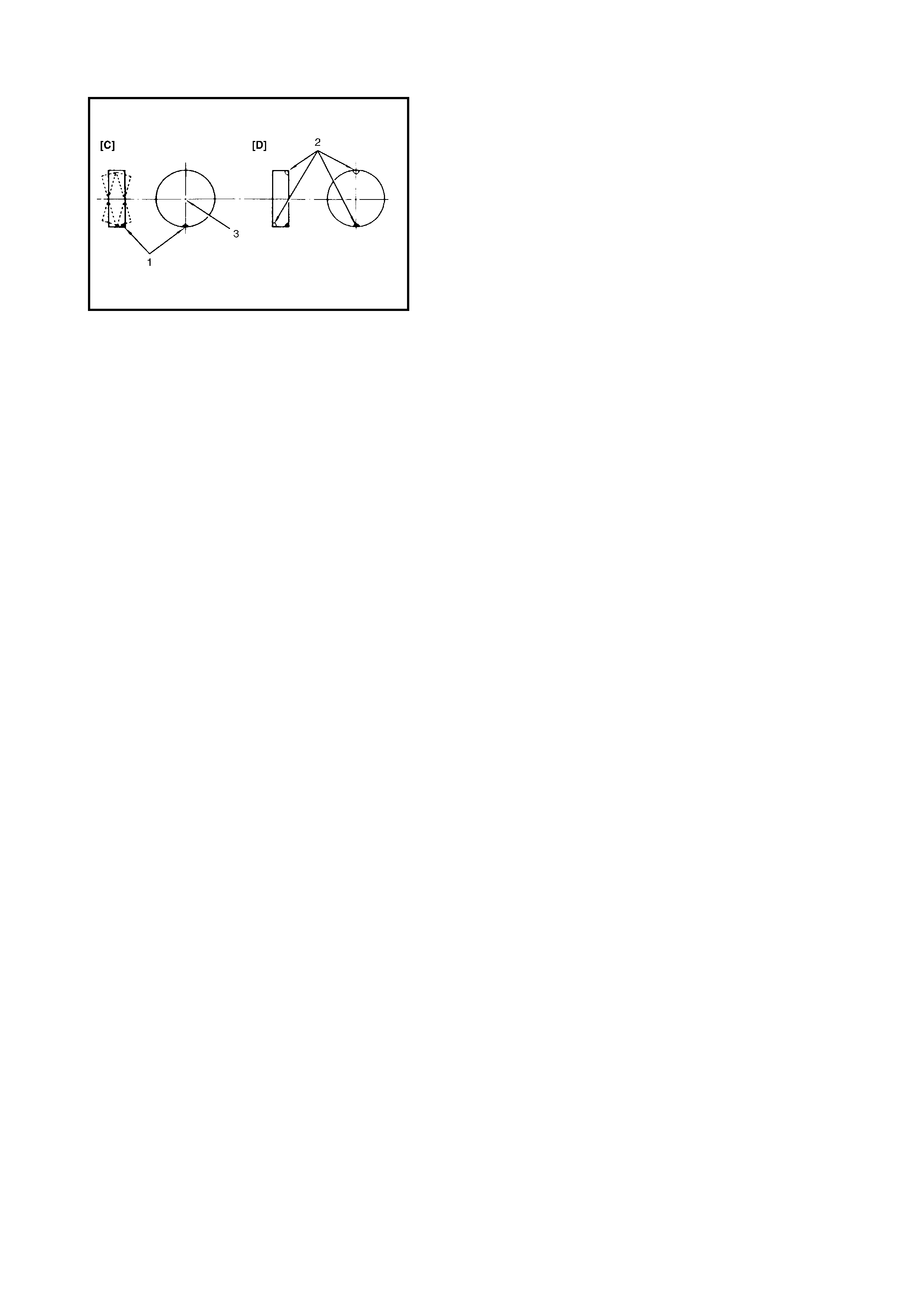
Dynamic balance, as shown in the figure, i s the equal distri-
bution of weight on each side of the wheel centreline so
that when the tyre spins there is no tendency for the
assembly to move from side to side. Wheels that are
dynamically unbalanced may cause shimmy
Legend.
2.3 GENERAL BALANCE PROCEDURES
Deposits of mud, etc. must be cleaned from inside of rim.
WARNING: Stones should be removed from the tread in order to avoid operator injury during spin
ba lan c i ng and to obt ain good bal anc e.
Each tyre should be inspected for any damage, then balanced according to equipment manufacturer’s recom-
mendation.
OFF-VEHICLE BALANCING
Most electr onic off -veh icle b alancers are more ac curate than t he on-vehicle spin ba lancers. T hey are eas y t o
use and giv e a dynamic (two plane) balance. Although they do not correct for drum or disc unbalance as does
on-vehicle spin balancing , this is overcome by their accuracy, usually to with in 1/8 ounce.
ON-VEHICLE BALANCING
On-vehicle balancing metho ds var y with equi pment and tool manufacturers. Be sure to foll ow each manufac-
turer’s instructi ons during balancing operation.
WARNING: Wheel spin should be limited to 55 km/h as in dicated on the speedometer.
This limit is neces sary because the speedometer only indicates one -half of actual wh eel speed when
one drive wh eel is spinn ing and the other drive wheel is stationery.
Unless care is taken in limiting drive wheel spin, the spinning wheel can reach excessive speeds. This
can result in possible tyre disintegration or differential failure, which could cause serious personal
in j ury or exte nsive ve hicle da m a ge.
CAUTION: F or ve hicles eq uippe d w ith A BS, us ing t he on -ve hicle bal ancin g met hod with t he ig nition
switch ON, may set a malfunc tion diagnostic trouble code (DTC) for the ABS even when the system is
in good co nditi on.
Never turn the ignition switch ON while the wheels are spinning.
1. Heavy spot wheel sh immy [C] : Before correction
2. Balance weights addition
point [D] : Corrective weights
3. C/L of spindle

3. MAINTENANCE AND MINOR ADJUSTMENTS
3.1 WHEEL MAINTENANCE
Wheel repairs that use welding, heating, or peening are not approved. All damaged wheels should be
replaced. WHEEL ATTACHING STUDS
If a broken stud is found, refer to Section 3E REAR SUSPENSION or Section 3D FRONT SUSPENSION for
notes and replacem ent procedures.
3.2 TYRE MAINTENANCE
TYRE PLACARD
The Tyre Placard is located on the right door lock pillar and should be re ferred to for tyre infor mation .
INFLATION OF TYRES
The pressu re recomm ended for any model is carefully calculated to give a satisfactor y ri de, stability, steer ing,
tread wear, tyre life and resistance to bruises.
Tyre pressure, w ith t yres cold, (after vehicle has sat for 3 hours or more, or dri ve n less th an one mile) should
be checked mont hly or be fore any extended trip. Inflate to the specifications on the “Tyre Placard” located on
the righ t door lock pillar.
It is normal for tyre pressure to increase when the tyres become hot during driving.
Do not bleed or re duc e tyre pressure after driving. Bleeding reduces the “Cold Inflation Pressure”.
Higher than rec omm en ded tyre pressure can cau se:
• Hard ride
• Tyre bru ising or carcass damage
• Rapid tread wear at centre of tyre
Unequ al tyre pressur e on same axle can cau se:
• Uneven bra king
• Steering lead
• Reduced handling
• Swerv e on acceleration
Lower than recommended tyre pressure can cause:
• Tyre squeal on tur ns
• Dif ficu lty Steerin g
• Rapid and uneve n wear on the edges of the trea d
• Tyre rim bru ises and rupt ure
• Tyre cord breakage
• High tyre temper ature
• Reduced handling
• High fuel consumption TYRE ROTATION
To equalise wear, rotate tyres according to the accompan y-
ing figure. Radial tyres should be rotated periodically.
Ensure correct tyre pressures are set.
NOTE: D ue to t heir design, radial tyres te nd to wear fa ster
in the shou lder area, particul arly on t he front of the vehicle.
This makes regular rotation especially necessar y.

4 . ON-VEHICLE SERVIC E
4.1 WHEEL
REMOVAL
1. Loose n wheel nuts by approximately 180° (half a
rotation).
2. Hoist vehicle.
3. Remove wheel.
CAUTION: Never use heat to loosen tight wheel nuts
because application of heat to the wheel can shorten
the life of the wheel and damage whe el be arings.
INSTALLATION
For installation, rev erse removal procedure, noti ng the
following.
• Wheel nuts must be tightened in sequence and to
proper torque to avoid bending whee l or brake d isc .
NOTE: Before installing wheels, remove any build-up of
corrosion on wheel mounting surface and brake disc
moun ting surface by scraping and wire bru shing. Installing
wheels without good metal-to-metal contact on mounting
surfaces can cause wheel nuts to loosen, which could
result in a wheel coming off while the vehicle is moving.
Tightening order
:(A)-(B)-(C)-(D)
WHEEL NUT (a)
TORQUE SPECIFICATION 85 Nm

4.2 TYRE
INSTALLATION AND REMOVAL
Use a tyre changing machine to mount or dismount tyres. Follow equipment manufacturer’s instructions. Do
not use hand tools or tyre irons alone to change tyres as they may damage tyre beads or wheel rim.
Rim bead seats should be cleaned with a wire brush or coarse steel wool to remove lubricants, old rubber and
light rus t. Before m ounting or dismounting a tyre, bead area should be well lubricate d with approved tyre
lubricant.
After mounting, inflate to specified pressure shown on tyre placard so that beads are completely seat ed.
WARNING: Do not stand over tyre when inflating. Bead may break when bead snaps over rim’s safety
hump an d caus e serio us pe rsonal injury.
Do no t exceed s pecified pr essu re wh en inflating. If sp ecified pres sure will not seat b eads, deflate, re-
lubricate and reinflate.
Over in flation may cause bead to break and cause seri ous persona l injury.
Install val ve core and inflate t o proper press ure.
REPAIR
There are many different materials and techniques on the market to repair tyres. As not all of these work on all
types of tyres, tyre manufacturers have published detailed instructions on how and when to repair tyres.
These instr uc tions can be obtained from each tyre manufacturer.