
1. GENERAL DESCRIPTION
1.1 COMPONENTS
The wheel-side of the front drive shafts use fixed, ball type constant velocity joints. The transaxle or transfer
ends use doub le offset type constant velocity joints. The drive shafts can slide through the double offset joints
(DOJ) in the extension/contraction direction.
2. DIAGNOSIS
2.1 DIAGNOSIS TABLE
2.2 DRIVE SHAFT BOOT CHECK
Inspect the drive shaft boot for tears.
If even a small tear is noted, replace the boot.
Co ndition Pos s ible C a use Co rrection
Abnormal Noise Worn or broken drive shaft joint Replace.
Worn or broken ce ntre spline shaft or hole Replace.
3 . ON-VEHICLE SERVICE
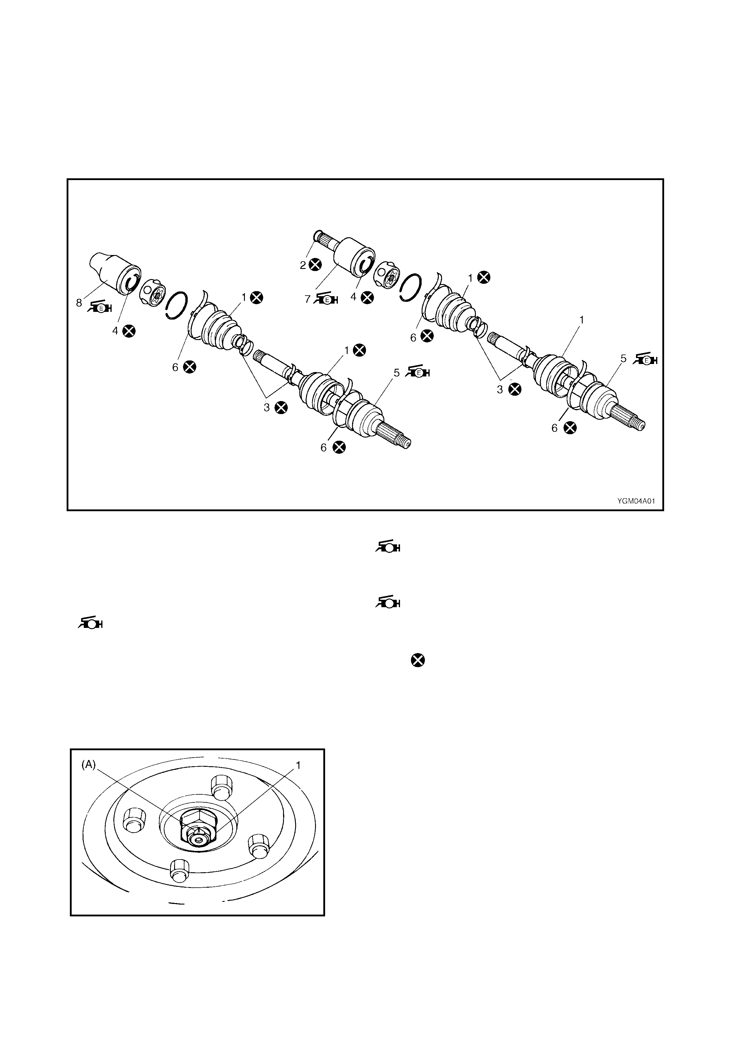
Legend
3.1 DRIVE SHAF T ASSEMBLY
REMOVAL
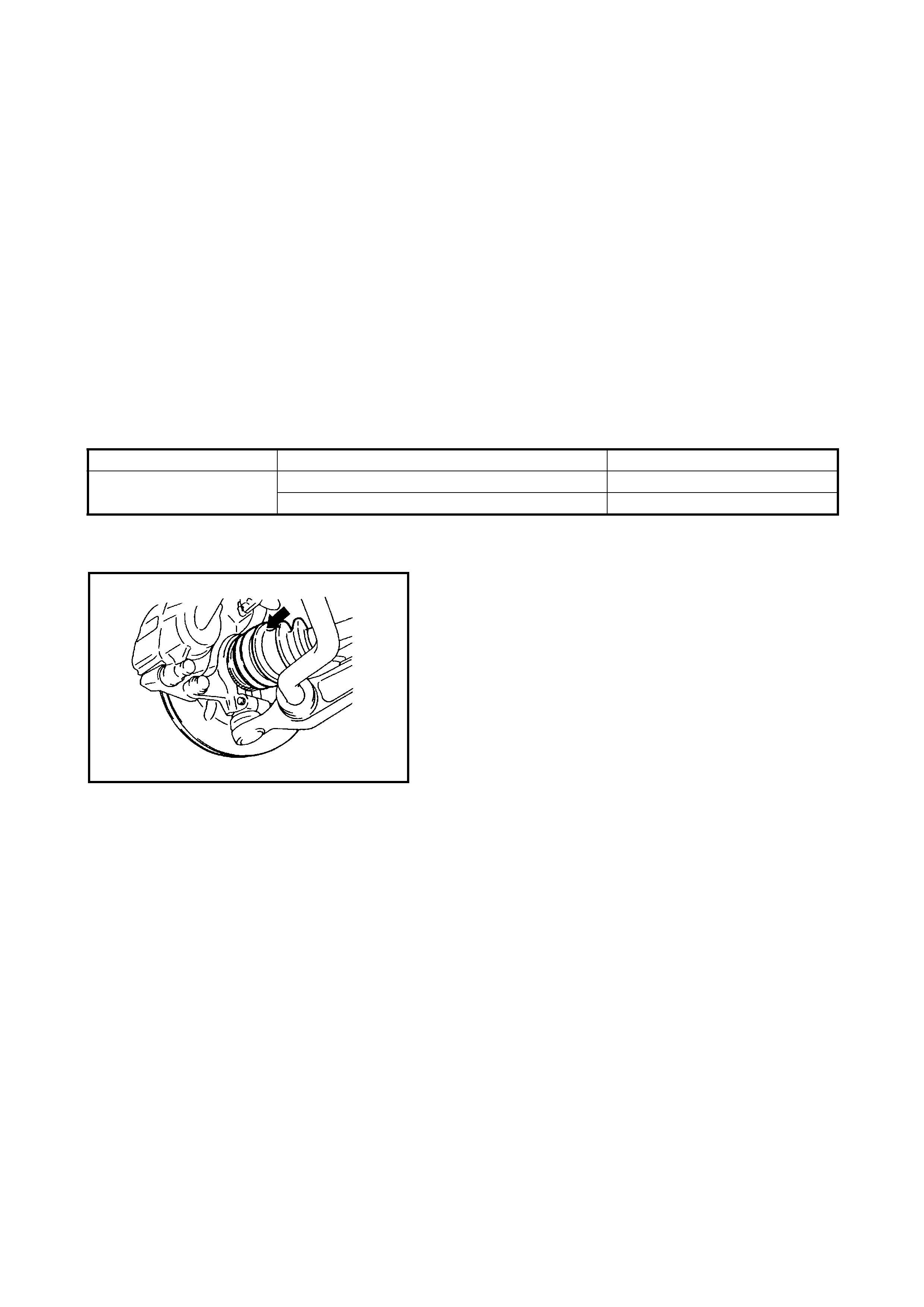
1. Unstake (A) and remov e drive s haft nut (1) and washer.
2. Raise vehicle on hoist.
3. Remov e the wheel.
1. Boot 7. Side joint (LH)
: Apply black grease incl uded in spare
par t to joint
2. Circlip
3. Boot band (Small)
4. Snap ring 8. Transfer side joint (RH)
: Apply black grease incl uded in spare
pa rt to jo in t.
5. Wheel side joint (Constant velocity joint)
: Apply black gre as e included in spare
pa rt to join t. Do not reuse.
6. Boot band (Large)
4. Drain the transaxle or transfer oil, refer to Section 7A
MANUAL TRANSMISSION or 7B AUTOMATIC
TRANSMISSION and 7D TRANSFER.
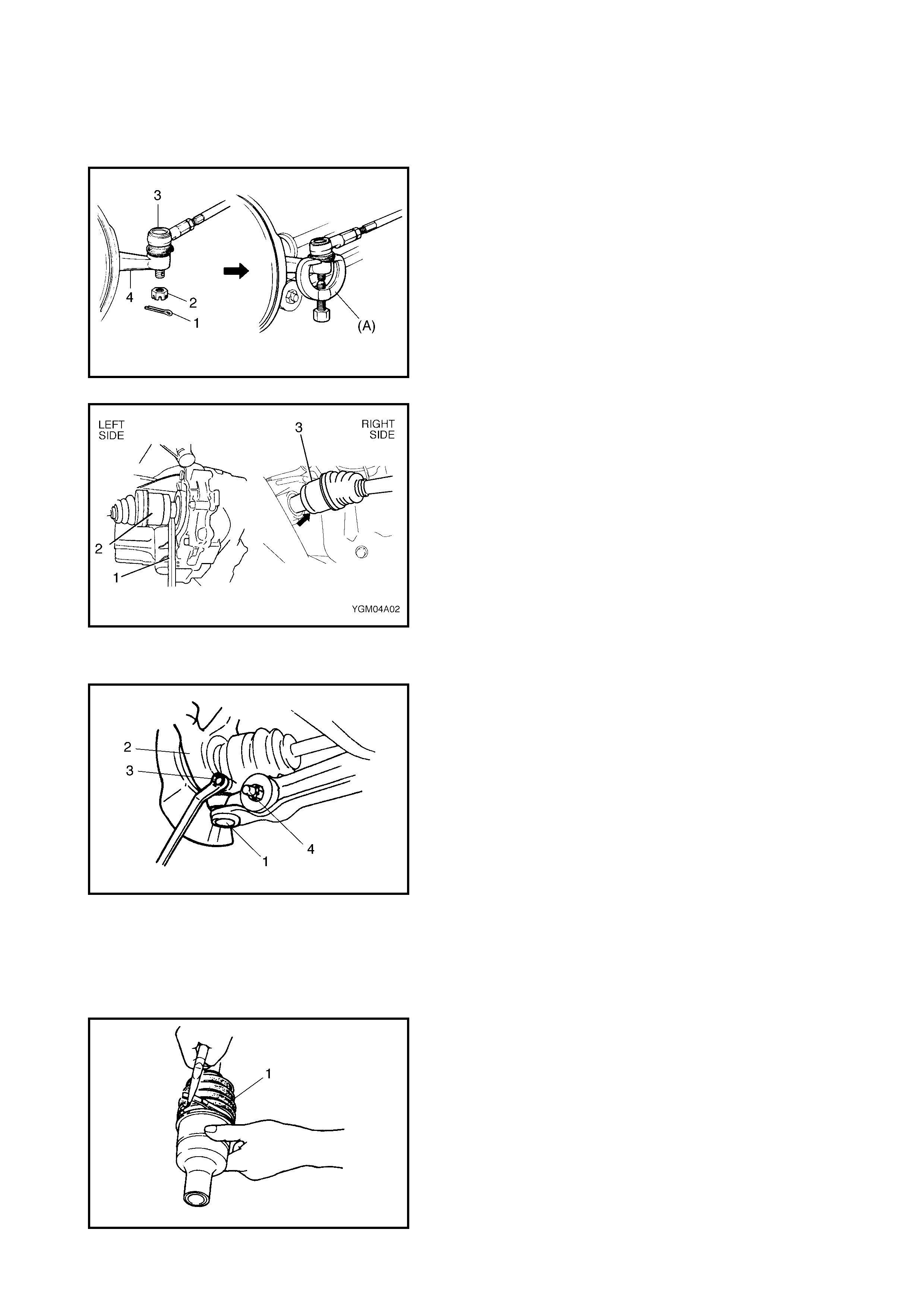
5. Remove the tie rod end split pin (1) and castle nut (2).
6. Disconnect the tie rod end (3) from the steering
knuckle (4) using special tool 09913-65210 (A).
7. Left side:
Using a tyre le ver (1) or similar, leve r out t he drive shaft
joint (2) to allow the snap ring fitting to be released
from the joint spline on the differential-side.
Right side:
Using plastic hammer, knock out the drive shaft joint
(2) to allow the snap ring fitting to be released fro m the
joint spline on the intermediate shaft of the tr ansfer.
8. Remove the two stabiliser mount brackets from the
vehicle body.
9. Disconnect the front suspension control arm ball stud
(1) from the steering knuckle (2) by pushing down on
the stabiliser bar (4) after removing the ball stud bolt
(3).
10. Remove driv e shaft assembly.
CAUTION: Take care not to damage the rubber boots
when removing the drive shaft assemb ly.
DISASSEMBLY
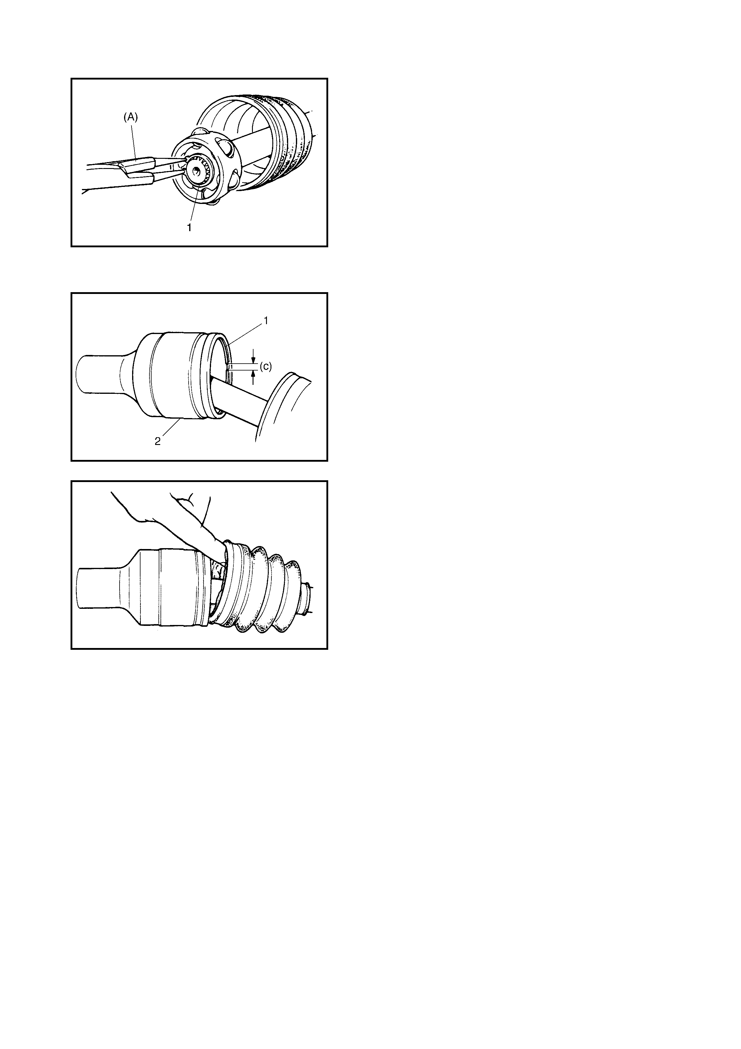
1. Remove the large boot band (1) from the differential-
side joint.
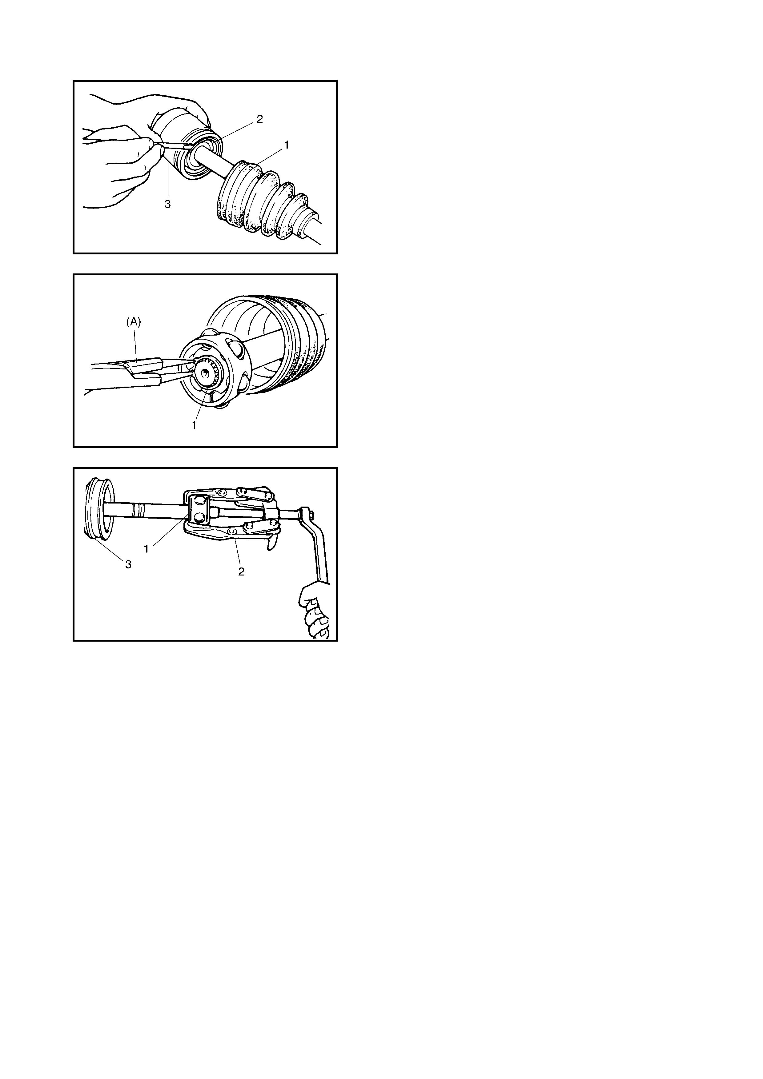
2. Slide the boot (1) towards the centre of the shaft and
remove the snap ring (2) from the joint housing.
Remov e the shaft from the joint housing (3).
3. Wipe off the grease and remove the circlip (1) used to
secure the cage using special tool 09900-06107(A).
4. Pull away the c age (1) using a bearing puller (2).
5. Remove t he sm all boot band then rem ove the d ifferen-
tial-side boot from the shaft.
6. Undo the large and small boot bands from the wheel-
side joint boot and remove t he boot from the shaft.
CAUTION: Do not disassemble wheel-side joint. If
there are any signs of breakage or wear, replace as a
compl ete assembly.

ASSEMBLY
After assessing wear and damage noted before disassem-
bly, verify through visual i nspec tion and determ ine replace-
ment part s required.
Make sure that the w heel-side joint assembly (1) and DOJ
housing (2) are washed thoroughly and air dried. Rubber
boots (3) should be clean ed with a clean cloth if they are to
be reused.
CAUTION: To ens ure new joints p erform as designed,
be sure the correct type and quantity of grease is used.
1. Wash disassembled parts (except boots). After
washing, dry parts completely with compressed air.
2. Clean boots with cloth. Do not wash boots in
degreaser, such as gasoline or kerosene, etc.
Washing in degreaser can cause deterior ation of boot.
3. Apply grease to wheel side joint. Use specified grease
in tube included in wheel side boot set.
4. Install wheel side boot on shaft, fill up inside of boot
with grease then fast en boot with bands (1).
CAUTION:
• Bend each boot band against forward rotation (A).
• Do not squeeze or distort boots when fastening
them with bands.
5. Fit the new differential-sid e band (small) and the
differ ential-side boot on the driv e shaft temporarily.
6. Drive in the cage (1) using a pipe (2) as shown in
figure.
CAUTION: Install cage with smaller outside diameter
facin g the wheel side .
BLACK GREASE (A) 45 - 65 gm
BLACK GREASE (B) [LIGHTER T HAN (A)]
LEFT SIDE SHAFT
(EXCEPT A/T VEHICLES)
LEFT SIDE SHAFT ( A/T VEHI CLES ONLY) 70 - 90 gm
55 - 75 gm
DRIVE SHAFT JOINT CA GE
INSTALLATION PIPE DIAMETER (a) 22.5 mm or MORE
DRIVE SHAFT JOINT CA GE
INSTALLATION PIPE DIAMETER (b) 30.0 mm or LESS
7) Install circlip (1) using special tool 09900-06107
(A).
8. Appl y grease to the entire surface of the cage.
Use specified g rease in tube included in spare parts.
9. Insert the cage into the joint housing and fit the snap
r ing (1) into the groove of the joint housing (2).
CAUTION: P osition the opening of the snap ring (c) so
that it is not in line with a ball.
10. Apply grease to the inside of the joint housing and fit
the boot. Once fitted, insert a screwdriver under the
edge of the boot on the joint housing side, to allow air
to enter the boot cavity. This equalises the air press ure
in the boot with the atmospheric pressure.
11. When fixing the boot (1) t o the joi nt housing (2) with the
differential-side band (l arge) (3), adj ust to t he measure-
ments indicated below.
CAUTION: Do no t wash joint bo ots. Cl ean wi th a cloth
only.
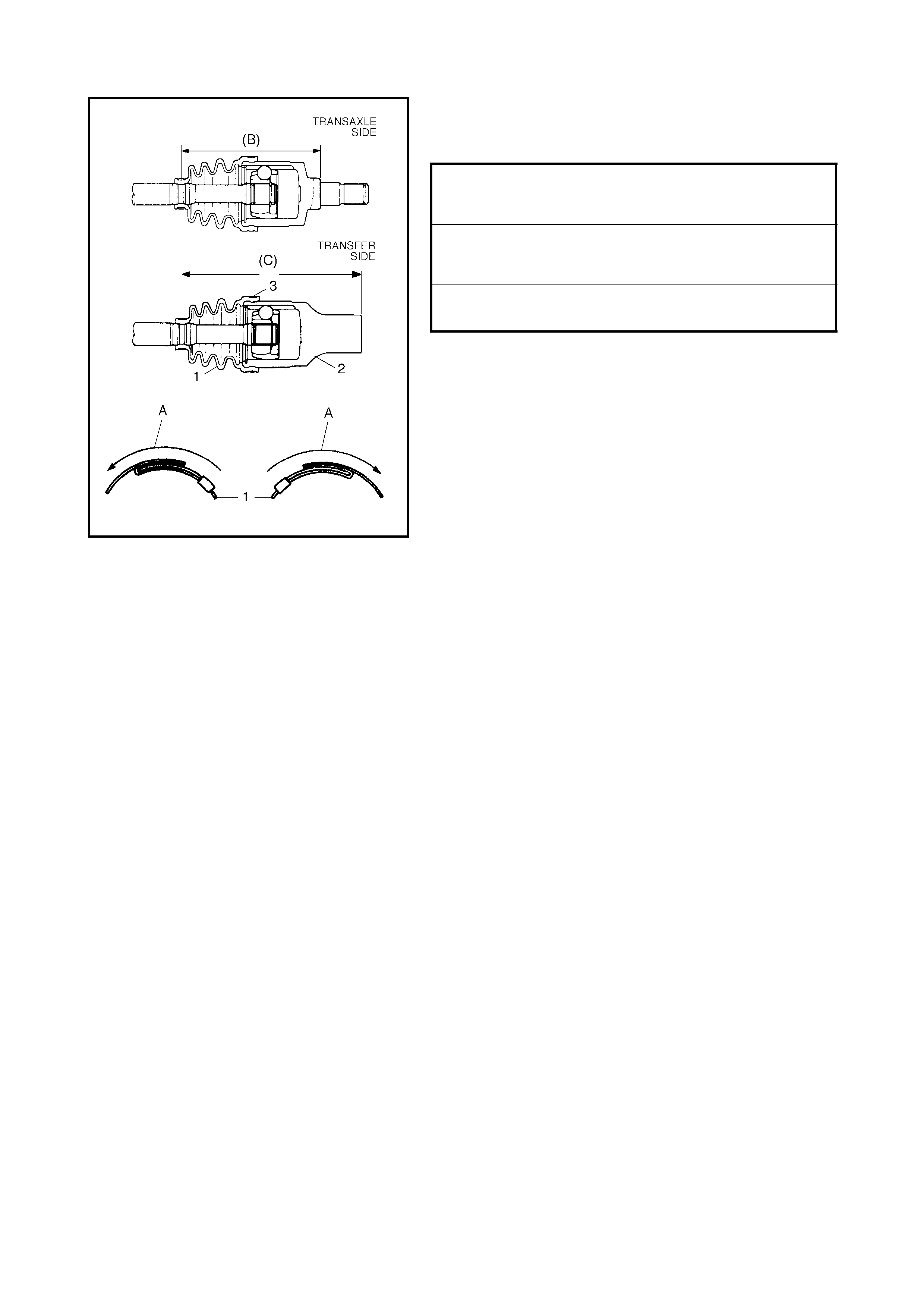
• Bend each boot band against forward rotation (A).
• Do not squeeze or distort boot when fastening it
w ith band s .
INSTALLATION
CAUTION:
• Avoid excessive expansion of boot and conse-
quential disconnection of joint in boot when
installing drive shaft.
• Protect oil seals and boots from damage when
installing drive shaft.
• Do not hit joint boot with hammer. Insert joint by
hand on ly.
• Make su re th at the differential-side joint is inser ted
fully and its snap ring is seated c orre ctly.
Install the drive shaft assembly by reversing remov al proce-
dure and noting the f ollowing points.
DRIVE SHAFT BOOT FIXING POSITION
LEFT SIDE DRIVESHAFT
ON A/T VEHCILES (B) 147.0 mm
DRIVE SHAFT BOOT FIXING POSITION
LEFT SIDE DRIVESHAFT
ON M/T VEHCILES (B) 162.5 mm
DRIVE SHAFT BOOT FIXING POSITION
RIGHT SIDE DRIVESHAFT (C) 196.5 mm
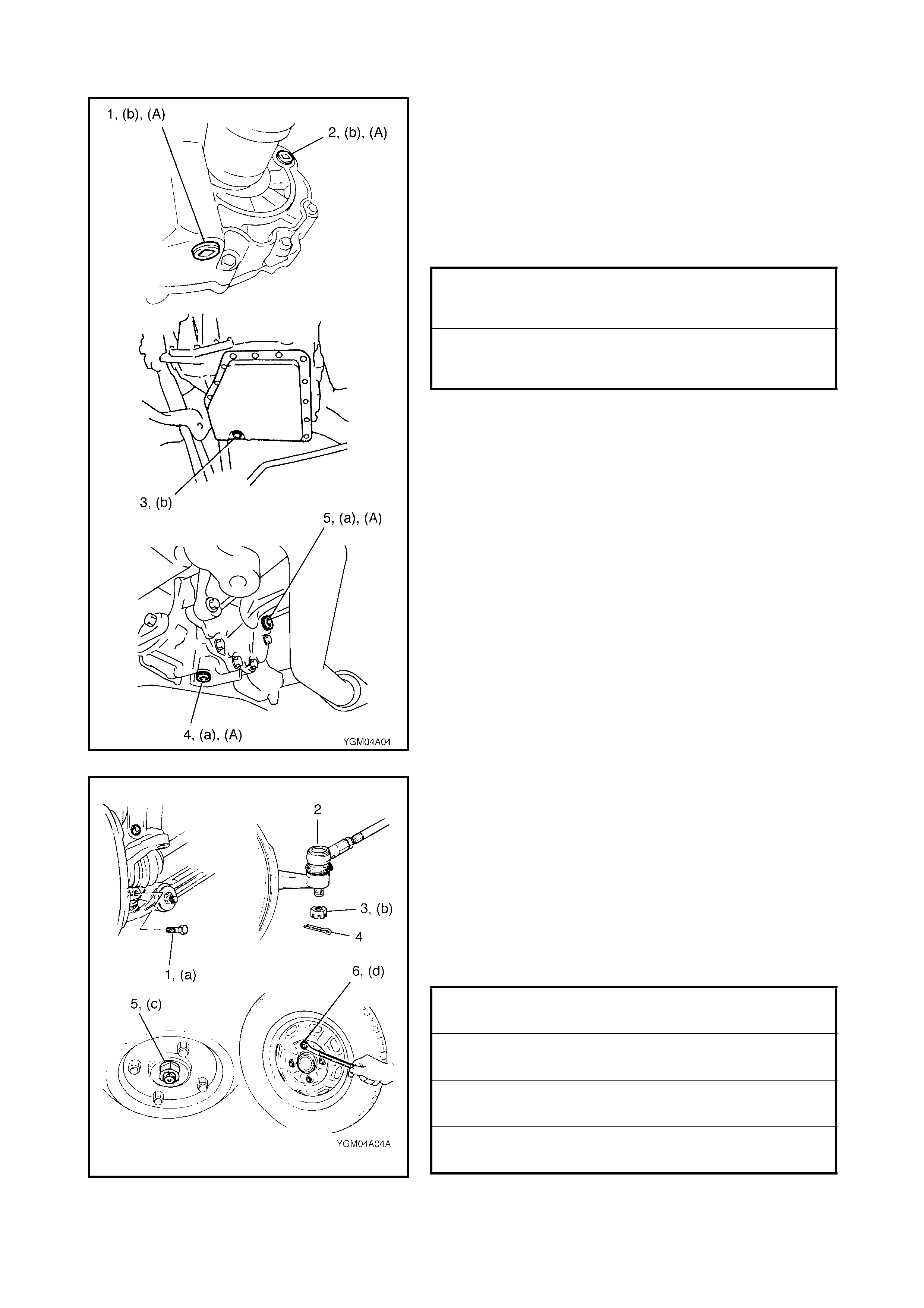
• Tighten each bolt and nut to the specified torque.
• Apply sealant to drain plug (1) and filler/level plug (2)
on manual transmission vehicles.
(A): Sealant - Three Bond No. 1216B
• Refit drain plug (3) on automatic transmission vehicles.
• Apply sealant to drain plug (4) and filler/level plug (5)
on transfer.
(A): Sealant - Three Bond No. 1216B
• Refit ball stud bolt (1).
• Connect tie rod end (2) to steering knuckle and tighten
tie rod end castle nut (3).
• Install new split pin (4) and bend pin ends securely
against castle nut.
• Depress foot brake pedal and hold. Install new drive
shaft nut (5) and washer.
• Stake drive shaft nut, refer to Section 3D, 3.3 WHEEL
HUB AND STEERING KNUCKLE.
• Fit wheel and tighten wheel nuts (6).
• Fill transmission or transfer with oil as specified, refer
to Section 7A MANUAL TRANSMISSION,
7B AUTOMATIC TRANSMISSION or 7D TRANSFER.
TRANSFER OIL FILLER/LEVEL AND
DRAIN PLUGS (a)
TORQUE SPECIFICATION 21 Nm
TRANSMISSION OIL FILLER/LEVEL
AND DRAIN PLUGS (b)
TORQUE SPECIFICATION 21 Nm
BALL STUD BOLT (a)
TORQUE SPECIFICATION 60 Nm
TIE ROD AND CASTLE NUT (b)
TORQUE SPECI FICATI ON 30 - 55 Nm
DRIVE SHAFT NUT (c)
TORQUE SPECIFICATION 175 Nm
WHEEL NUT (d)
TORQUE SPECIFICATION 85 Nm
4. REQUIRED SERVICE MATERIAL
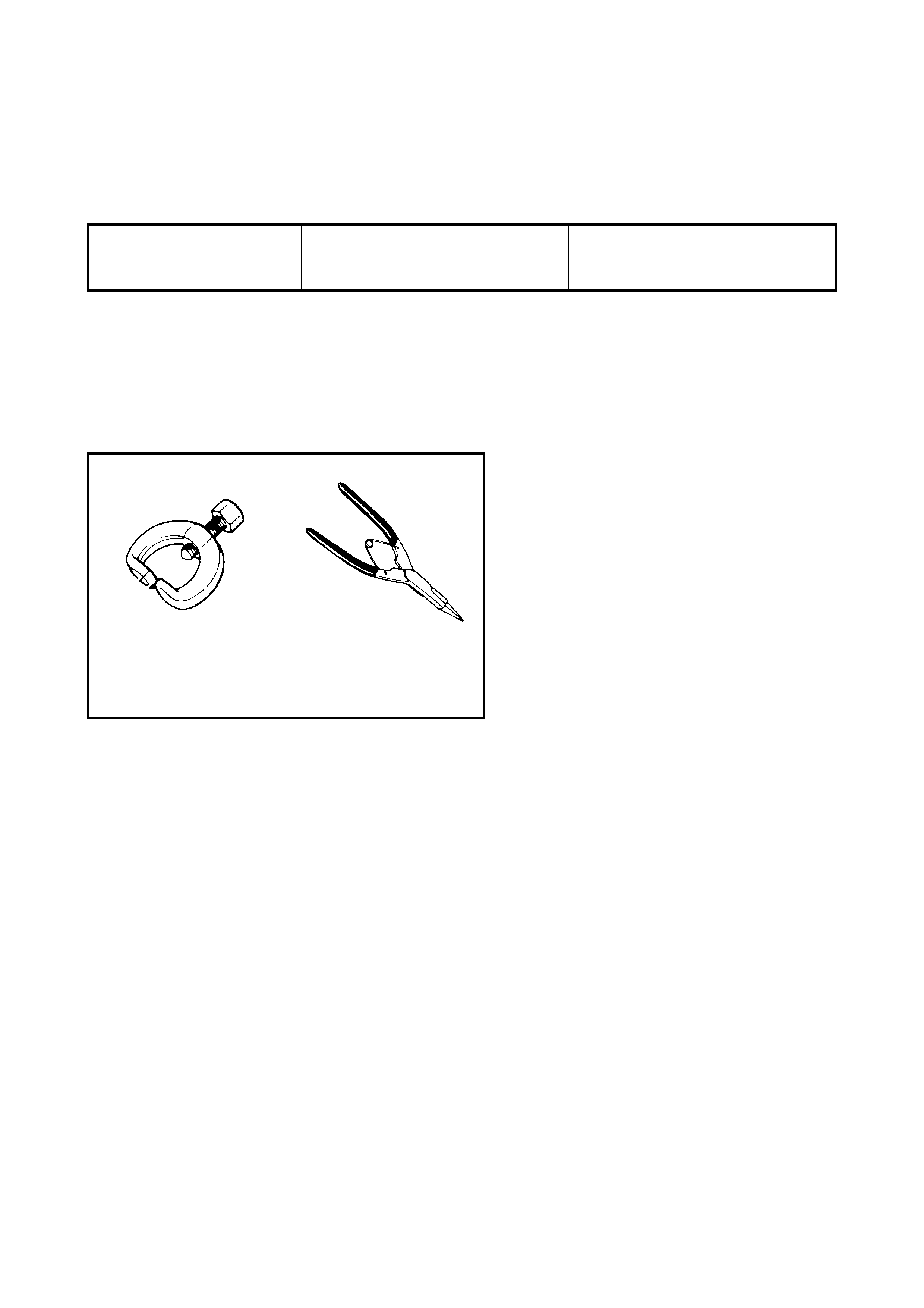
5. SPECIAL TOOLS
NOTE: Refer to Section 0A GENERAL INFORMATION – 7. CONSOLIDATED TOOLS for a detailed list of
special tools and the local equivalent if on e is available.
Material Recom mend ed Product Use
Sealant Three Bond No. 1216B • Oil drain and filler plug for manual
transa xle or tran sfe r
09913-65210 09900-06107
Tie-rod end remover Snap ri ng pliers (Open
type)