

1. GENERAL DESCRIPTION
The universal and constant velocity joints used on this vehicle require no maintenance. They are lubricated for
life and cannot be lubricated on the vehicle. If the universal and constant velocity joints becomes noisy or
wor n, they must be replaced.
The propelle r shaft is a balanced unit. Handle it carefully to avoid damage and loss of balance.
A viscous coupling is used for the coupling system which distributes optimum driving force to the front and
rear wheels according to the driving conditions. It is located between the propeller shafts.
2. DIAGNOSIS
DIAGNOSIS TABLE
2.1 PROPELLER SHAFT JOINT CHECK
If the universal joints are suspected as the cause of chat-
tering or rattling noises, inspect them for wear. Check to
see if the cross spider rattles in the yoke. If propeller shaft
is defective replace with a new one.
Noise coming from a universal joint can be easily distin-
guished from other noises because the rhythm of chatter-
ing or rattling is in step with the cruising speed. Noise is
pronounced, particularly with a standing start or while
coasting (when the br aking eff ect of the engine is rel ayed to
the dr ive line).
Condition Possible Cause Correction
Abnormal noise Loose univ ersal joint bolt Tighten univers al joint bolt .
Spider bear ing wor n or seized Replace.
Worn or broken constant velocity joint Replace.
Worn or broken centre support bearing Replace.
Broken centre support rubber Replace.
Worn spider Replace propeller shaft.
Vibration Performed propell er shaft Replace.
3. ON-VEHICLE SERVICE
Legend
PR ELIM I N A RY I N SPEC T I ON
• Check the propeller shaft connecting bolts for tight-
ness. If they are found to be loo se, tighten to spec ified
torque.
• Check the propeller shaft joints for wear, rattle and
damage. If any defects are found, replace.
• Check the propeller shaft centre support for intrusion of
foreign matter, cracks, abnormal noise and damage. If
any defects are found, replace.
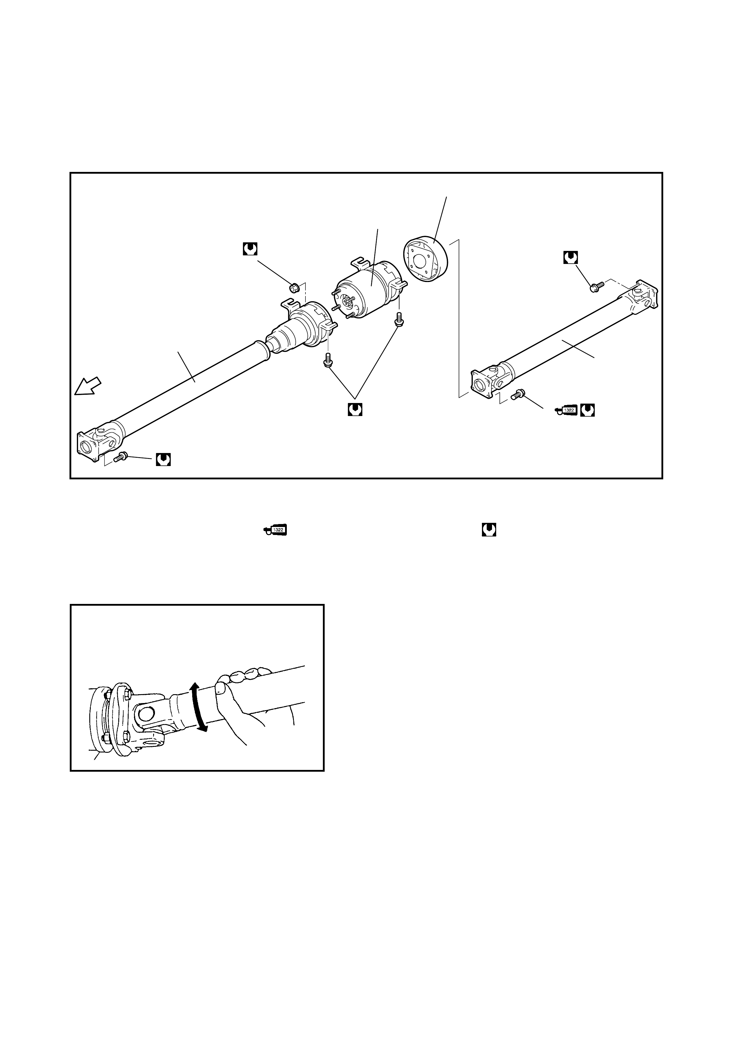
23 Nm
1
55 Nm 4
3
23 Nm
23 Nm
23 Nm
5
2
FRONT
1. Propeller shaft No.1 with 3. Propeller shaft No.2 5. Dynamic dam per
centre support 4. Propeller shaft No.2 bolt Tightening torque
2. Viscous coupling with : Apply thread lock
centre support cement 1322 to thread.
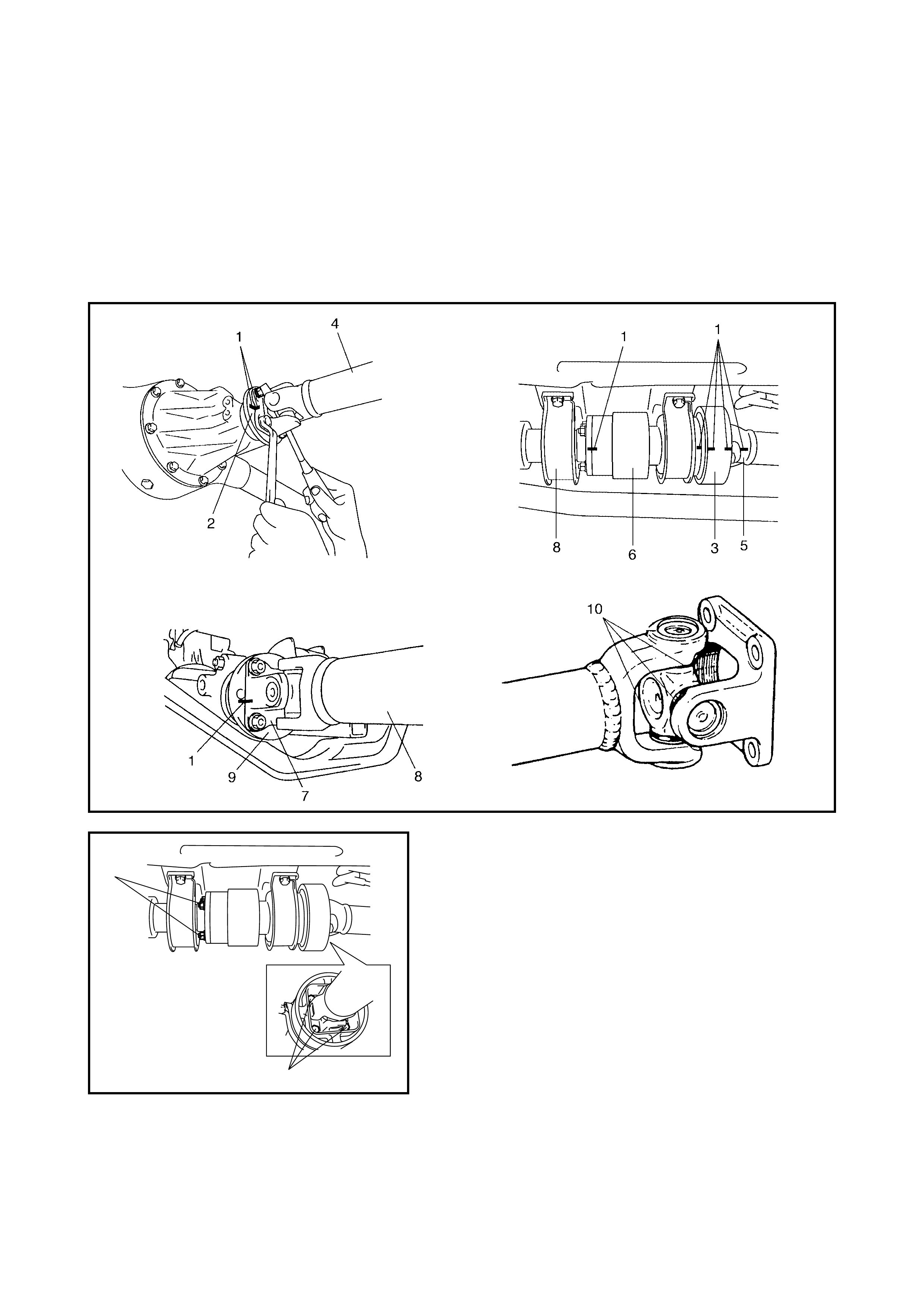
REMOVAL
1. Raise vehicle on hoist.
2. Before removing the propeller shafts, make alignment marks (1) on the propeller shaft No.2 (4) and the
companion flange (2) of the rear differential as shown. Also make alignment marks (1) on the propeller
shaft No.2 yoke (5), the dynam ic dam per (3), the visc ous coupli ng with cent re support (6), the yoke (7) of
propeller shaft No .1 with centre support (8) and the transfer case output flange (9).
CAUTION: Take care not to damage joint seals (10) or lubrication of joint will be affected.
3. Loosen the propeller shaft bolts at the front and rear end, and separate the propeller shafts from the
transfer case and re ar differential.
4. If it is necessary to disassemble the propeller shaft
assemb l y, loosen, b ut do not remov e t he propeller s haft
No.2 bolts (1) and the viscous coupling nuts (2). This
will allow easier disassembling when shafts are
removed.
1
2
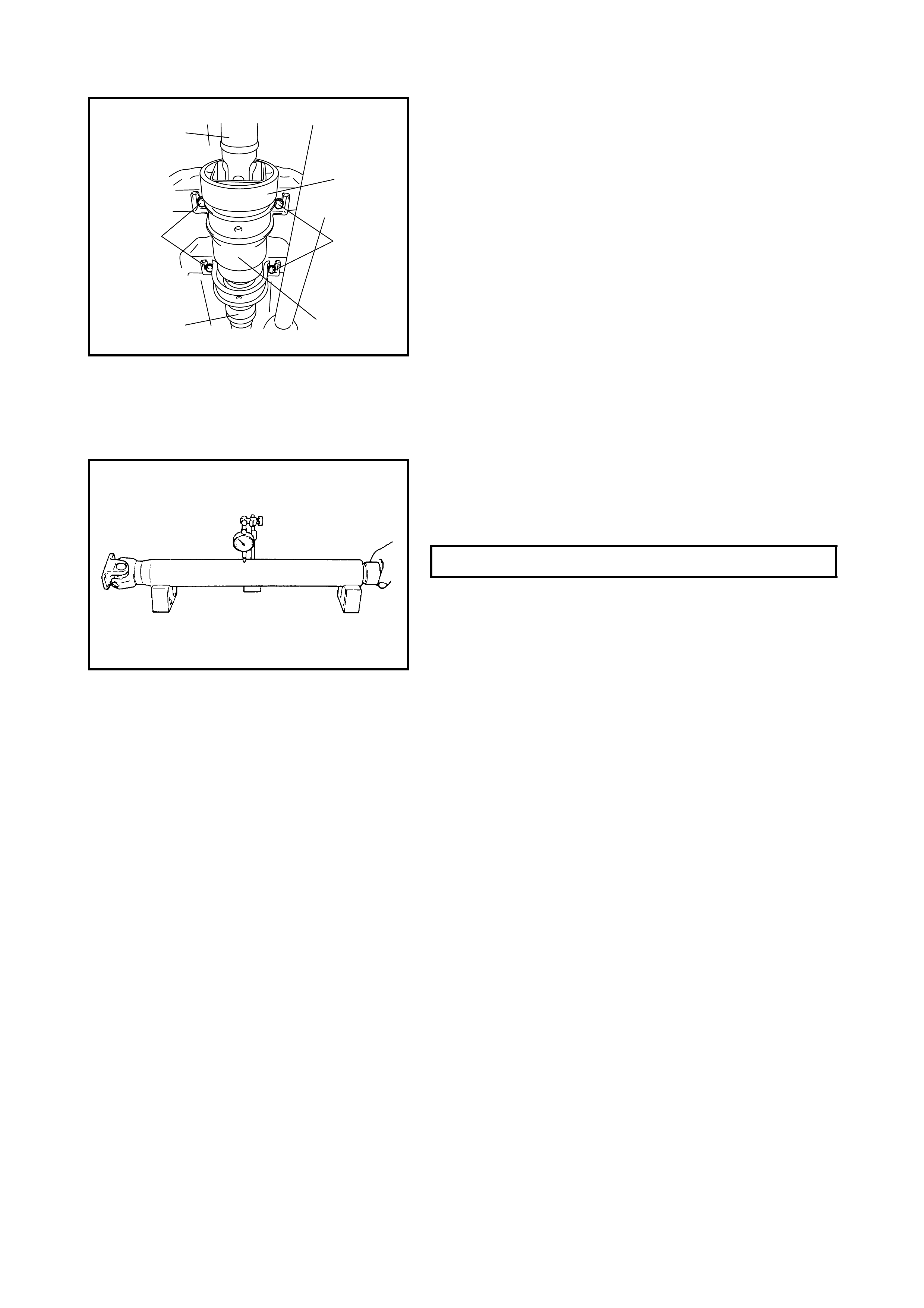
5. Loosen the centre support bolts (1), then remove the
propeller shaft No.1 with centre support (2), propeller
shaft No.2 (3), dynamic damper (5) and viscous
coupling with centre support (4) as a compl ete unit.
6. Disconnect the propeller shaft No. 1 wit h centre support
and the propeller shaft No.2 from the viscous coupling.
INSPECTION
•Inspect propeller shaft and flange yok e f or damage.
•Inspect propeller shaft for runout .
If damage is found or shaft runout exceeds its limit,
replace shaft.
3
1
24
1
5
PROPELLER SHAFT RUNOUT LIMIT 0.7 mm
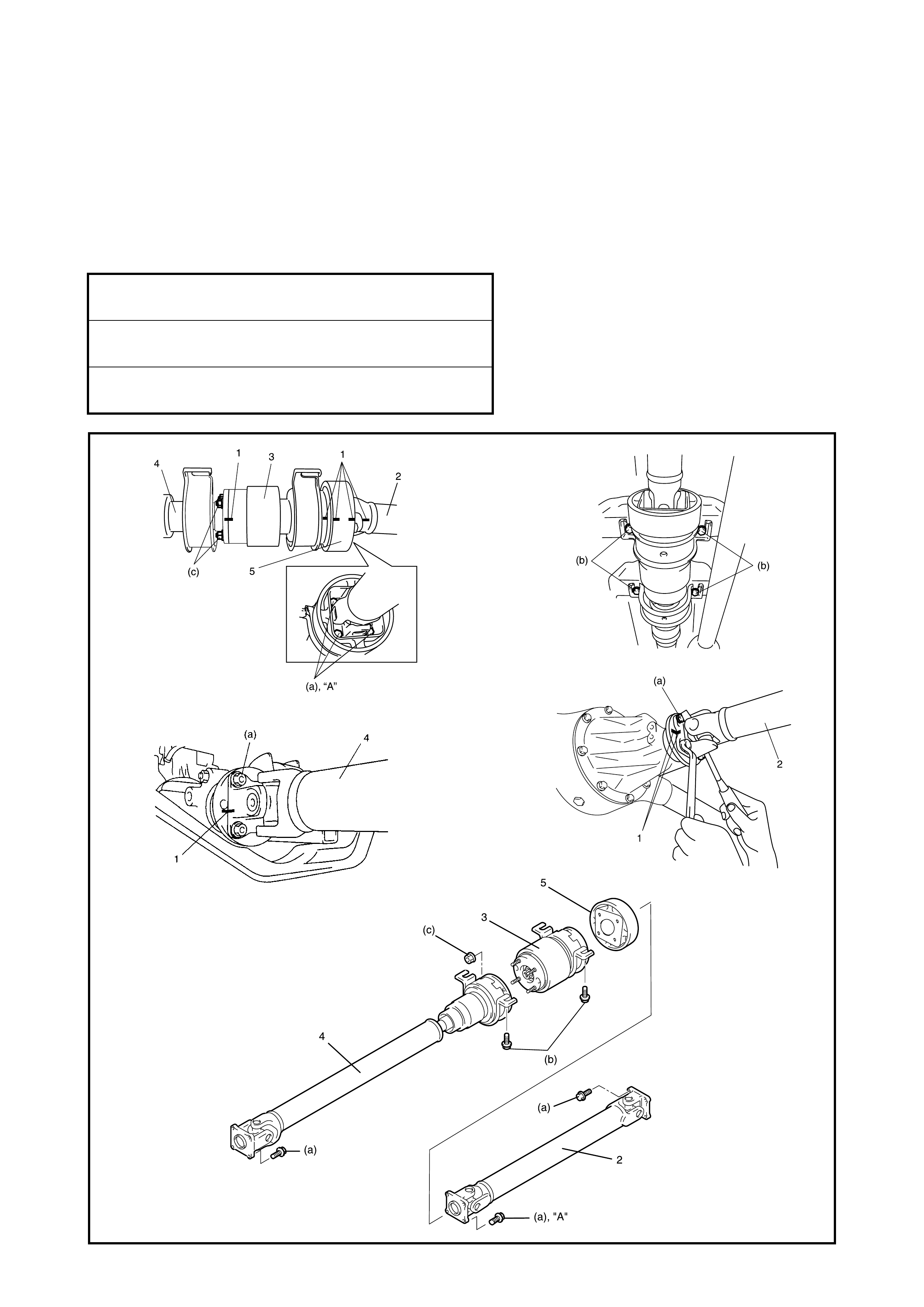
INSTALLATION
Reverse the removal procedure to install the propeller shafts noting the following points.
•When installing the propeller shaft No .2 (2), propeller s haft No.1 (4), dynamic damper (5) and viscous cou-
pling with centre suppor t (3), match the alignment mar ks (1) made before removal.
Fai lure to do so may cause vibration during dri ving.
•Apply thread lock cement to the threads of the propeller shaft No.2 bolts.
“A”: Thread Lock Cement 1322
•Torque bolts to the follo wing specifications.
PROPELLER SHAFT BOLTS (a)
TORQUE SPECIFICATI ON 23 Nm
CENTRE SUPPORT BOLTS (b)
TORQUE SPECIFICATI ON 55 Nm
VISCOUS COUPLING NUTS (c)
TORQUE SPECIFICATI ON 23 Nm
4. REQUIRED SERVICE MATERIAL
Ma te ri al Recom m ended produ c t Use
Thread lock cement THREAD LO CK CEMENT 1322 •Propeller shaft No.2 bolt