
SECTION 5 - BRAKES
1. GENERAL DESCRIPTION
2. DIAGNOSIS
2.1 ROAD TESTING BRAKES
2.2 BRAKE FLUID LEAKS
2.3 SUBSTANDARD OR CONTAMINATED
BRAKE FLUID
2.4 DIAGNOSIS TABLE
2.5 BRAKE PEDAL FREE HEIGHT ADJUST-
MENT
2.6 BRAKE PEDAL PLAY INSPECTION
2.7 BRAKE LIGHT SWITCH ADJUSTMENT
2.8 EXCESSIVE PEDAL TRAVEL
INSPECTION
2.9 BRAKE DISC INSPECTION
2.10 PARKING BRAKE INSPECTION
AND ADJUSTMENT
Inspection
Adjustment
2.11 BOOSTER OPERATION INSPECTION
Check Air Tightness
Check Operation
Check Air Tightness Under Load
2.12 FLUID PRESSURE TEST (IF EQUIPPED
WITH LSPV)
2.13 MASTER CYLINDER AND BRAKE FLUID
LEVEL INSPECTION
2.14 BRAKE HOSE AND PIPE INSPECTION
Hose
Pipe
3. ON-VEHICLE SERVICE
3.1 AIR BLEEDING OF BRAKE SYSTEM
3.2 FRONT BRAKE
Brake Pad Removal
Inspection
Installation
Calliper Asse mbly Removal
Disassembly
Inspection
Assembly
Installation
Brake Disc Inspect ion
Removal
Installation
3.3 REAR BRAKE
Brake Drum Removal
Inspect ion - Brake Drum
Inspect ion - Brake Shoe
Installation
Brake Shoe Removal
Inspection
Installation
Wheel Cylinder Removal
Inspection
Installation
Brake Back Plate Removal and
Installation
3.4 MASTER CYLINDER
Master Cylinder Reservoir Removal
Master Cylinder Reservoir
Installation
Master Cylinder Assembly Removal
Disassembly
Inspection
Assembly
Inspect ion After Assembly
Master Cylind er Assembly
Installation
3.5 BRAKE BOOSTER
Removal
Installation
Inspect ion and Adjustmen t
NOTE:
• A ll suspension fasteners are important attaching parts that co uld aff ect the perf ormance of vital
parts and systems. They must be re place d with it ems of the sa me part number or w ith an equ iv a-
lent part if replacement becomes necessary. Do not use a replacement part of lesser quality or
subst itute design. Torque va lues must be used a s specifie d during r eassembly t o assure p roper
retention of the part.
• Never attempt to heat, quench or straighten any suspension part. Replace it with a new part or
damage to the part may result.

3.6 BRAKE HOSE/PIPE
Front Brake Hose/Pipe Removal
Installation
Non ABS Vehicles
ABS Vehicles
Rear Brake Hose/Pipe Removal
Rear Brake Hose/Pipe Installation
3.7 PARKING BRAKE CABLE
Removal
Installation
3.8 LSPV (LOAD SENSING
PROPOR TIONING VALVE ) ASSEMBL Y
(IF EQUIPPED)
Removal
Installation
Inspection and Adjustment
4. REQUIRED SERVICE MATERIAL
5. SPECIAL TOOLS
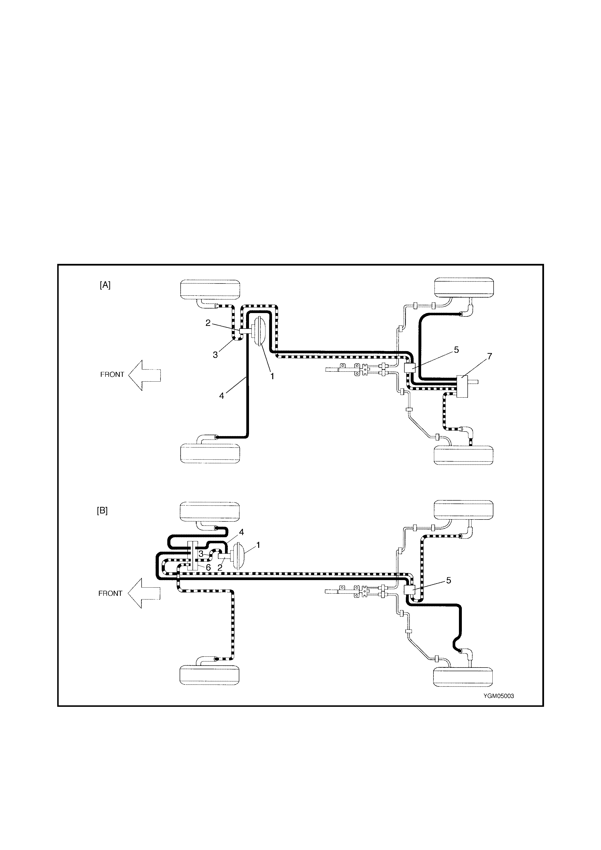
1. GENERAL DESCRIPTION
When the brake pedal is depressed, hydraulic pressure is generated in the master cylinder which actuates
pistons in the front disc brake calipers and rear drum brake wheel cylinders.
The m aster cylinde r is a tandem master cyl inder. The brake pi pes are conn ected to the master cyl inder and
form tw o independent circuits. One con nects right fron t & left rear brakes and the other c onnects left front &
right rear brakes.
The load sensing proportioning valve (LSPV) is included in the circuits between the master cylinder and the
rear brakes on non ABS vehicles.
The parking brake system is mechanical. It applies braking force to the rear wheels only via a cable and
mechanical linkage system. The same brake shoes are used for both the parking and foot brakes.
Legend
[A] : Non ABS vehicles 3. Secondary side 7. LSPV (Load Sensing
Proportioning valve)
[B] : ABS vehicle s 4. Primary side
1. Brake booster 5. 4-way joint
2. Master cylinder 6. ABS hydraulic unit/control
module assembly
2. DIAGNOSIS
2.1 ROAD TES T ING BRAKES
The brak ing sy stem sho uld be tested on a dr y, cl ean, s mooth a nd level roadw ay which is not c rowned . Road
test brakes by making brake applications with both light and heavy pedal forces at various speeds to deter-
mine if the vehicle stops evenly and effectively. Drive the vehicle to see if it leads to one side or the other with-
out brake application. If it does, check the tyre pressure, front wheel alignment and front suspension
attachments for looseness. Refer to 2.4 DIAGNOSIS TABLE in this Section for other causes.
2.2 BRAKE FLUID LEAKS
Check the master cylinder fluid levels. A slight drop in reservoir level will result from normal lining wear, an
abnormally low level indicates a leak in the system. If a leak is indicated, check the entire brake system for
leaks. Even if there is evidence of a slight leak, the cause should be corrected and the defective parts
replaced.
2.3 SUBSTANDARD OR CONTAMINATED BRAKE FLUID
Incorrect brake fluid, mineral oil or water in the brake system fluid may cause the brake fluid to boil or the rub-
ber components in the hydraulic system to deteriorate.
Swelling of the master cylinder primary piston cups is a sign that the rubber parts have deteriorated. This
deterioration may also be evidenced by swollen wheel cylinder piston cups on the drum brake wheels.
If deterioration of rubber components is evident, disassemble all hydraulic parts and wash with alcohol. Dry
these parts with com pres sed air befo re ass embly to kee p alc ohol out of the sys tem. R eplac e all r ubber parts
in the system, including hoses. Also, when working on the brake mechanisms, check for fluid on the linings or
pads. If excessive fluid is found, replace the linings or pads.
If the master cylinder piston seals are satisfactory, check for leakage or signs that the brake system has over-
heated. If leakage is not found, drain fluid, flush with brake fluid, refill and bleed system.
The s ystem mus t b e flu sh ed i f the re is an y d oubt as to th e gr ade of flui d i n the sy stem or if the flu id has been
used which parts that may be contaminated.
2.4 DIAGNOSIS TABLE
Condition Possible Cause Correction
Not enough braking
force Brake fluid leakage from brake lines Locate leaking point and repair.
Overheated brakes Determine cause and repair.
Poor contact of shoes on brake drum Repair for proper contact.
Brake shoes linings stained with oil or wet with
water Repair leak and replace.
Badly worn brake linings Replace pads or shoes.
Defective wheel cylinders Repair or replace.
Malfunctioning caliper assembly Repair or replace.
Air in system Bleed system.
Incorrect sensor spring length of LSPV, if
equipped Check or adjust.
Broken sensor spring of LSPV, if equipped Replace.
Defective LSPV, if equipped Replace.
Malfunctioning ABS (Antilock brake system), if
equipped Check system and replace as nec-
essary, refer to Section 5E
ANTILOCK BRAKE SYSTEM.
Brake pull
(Brakes not working
in unison)
Pad linings and/or shoe linings are wet or
stained with oil Repair leak and replace.
Drum-to-shoe clearance is out of adjustment
(Malfunctioning auto adjusting mechanism) Check for inoperative auto adjust-
ing mechanism.
Disc and/or drum is out of round Replace.
Tyres are inflated unevenly Inflate equally.
Malfunction in wheel cylinders Repair or replace.
Front wheels out of alignment Adjust as prescribed.
Unmatched tyres on same axle T yres with approximately the same
amount of tread should be used on
the same axle.
Restricted brake pipes or hoses Check for soft hoses and damaged
lines. Replace with new hoses and
new double-walled steel brake tub-
ing.
Malf unctio ning caliper assembly C heck for stuc k or slug gish pis tons
and proper lubrication of caliper
slide bush.
Caliper should slide.
Loose suspension parts Check all suspension mountings.
Loose calipers Check and torque bolts to specifi-
cations.
Noise (high pitched
squeak without brake
applied)
Front lining worn ou t Replace linings.
Contact wear indicator to brake disc Replace pads.
Rear brake locked
prematurely Maladjusted sensor spring length of LSPV, if
equipped Check or adjust.
Malfunction of the LSPV assembly, if equipped Replace assembly.
Excessive pedal
travel
(Pedal stroke too
large)
Partial brake system failure Check brake systems and repair
as necessary.
Insufficient fluid in master cylinder reservoirs Fill reservoirs with approved brake
fluid.
Check for leaks and air in brake
system.
Check warning light. Bleed system
if required.
Air in system (soft/spongy pedal) Bleed system.
Rear brake system not adjusted
(malfunctioning auto adjusting mechanism) Repair auto adjusting mechanism.
Adjust re ar brakes .
Bent brake shoes Replace brake shoes.
Worn rear brake shoes Replace brake shoes.
Brake locked
(For vehicle equipped
with ABS)
Malfunctioning ABS Check system refer to Section 5E
ANTILOCK BRAKE SYSTEM.
Condition Possible Cause Correction
Dragging brakes
(A very light drag is
present in all brakes
immediately after
pedal is released)
Maste r cyli nde r pisto ns not re tur ni ng corr ect ly Replace master cyli nde r.
Restricted brake pipes or hoses Check for soft hoses or damaged
pipes and replace with new hoses
and/or new double-walled steel
brake piping.
Incorrect parking brake adjustment on rear
brakes Check and adjust to correct
specifications.
Weakened or broken return springs in the
brakes Replace.
Sluggish parking brake cables or linkage Repair or replace.
Wheel cylinder or caliper piston sticking Repair as necessary.
Badly worn piston seal in caliper Replace piston seal.
Pedal pulsation
(Pedal pulsates when
depressed for
braking)
Damaged or loose wheel bearings Replace wheel bearings.
Distorted steering knuckle or rear axle shaft Replace knuckle or rear axle shaft.
Excessive disc lateral runout Check per instructions. If not within
specifications, replace or machine
disc.
Parallelism between pad and disc not within
specifications Check per instructions. If not within
specifications, replace or machine
disc.
Rear drums out of round Check runout.
Repair or replace drum as neces-
sary.
Braking noise Glazed shoe linings, or foreign matter stuck to
linings Repair or replace shoe linings.
Worn or distorted shoe linings Replace shoe lining (or pad).
Loose front wheel bearings Replace wheel bearing.
Distorted backing plates or loose mounting
bolts Replace or retighten securing
bolts.
Contact wear indicator to brake disc Replace pads.
Brake warning lamp
lights after engine
start
Parking brake applied Release parking brake and check
that brake warning lamp turns off.
Insufficient amount of bra ke fluid Add brake fluid .
Brake fluid leaking from brake line Investigate leaky point, correct it
and add brake fluid.
Brake warning lamp circuit faulty Repair circuit.
Malfunctioning EBD system, if equipped with
ABS. Check system refer to Table-E of
Section 5E ANTILOCK BRAKE
SYSTEM.
Brake warning lamp
turns on wh e n brake
is applied
Brake fluid leaking from brake line Investigate leaky point, correct it
and add brake fluid.
Insufficient amount of bra ke fluid Add brake fluid .
Brake warning lamp
fails to turn on even
when parking brake is
applied
Brake warning lamp circuit faulty Replace bulb or repair circuit.
ABS warning lamp
turns on after engine
start (If equipped)
Malfunctioning ABS Check system refer to
2. DIAGNOSIS of Section 5E
ANTILOCK BRAKE SYSTEM.
ABS warning lamp
turns on wh e n brake
is applied (If
equipped)
Malfunctioning ABS Check system referring to
2. DIAGNOSIS of Section 5E
ANTILOCK BRAKE SYSTEM.
Condition Possible Cause Correction
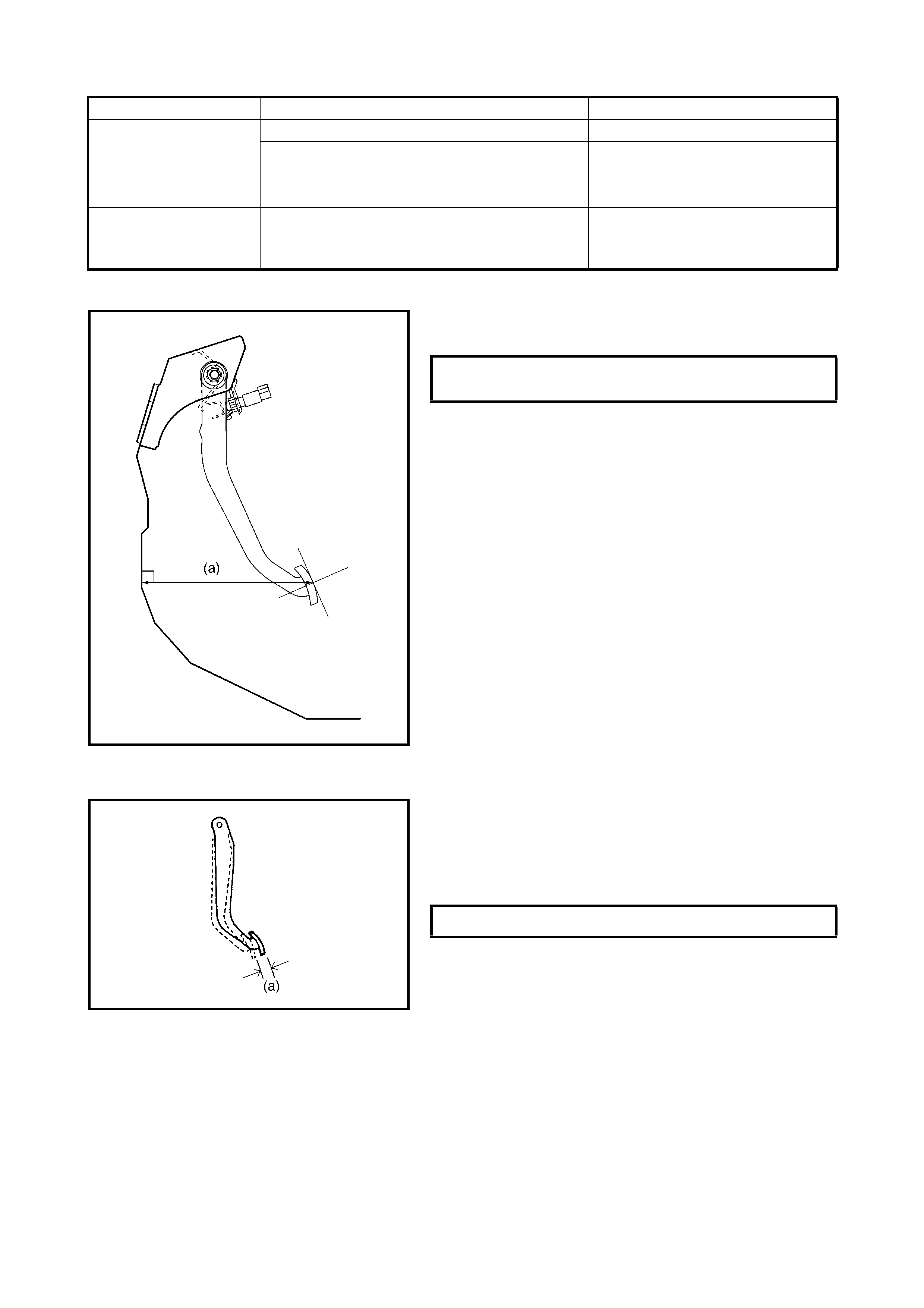
2.5 BRAKE PEDAL FREE HEIGHT ADJUSTMENT
Check brake pedal free height.
If it is not within specification, check and adjust as follows.
• Check measurement between booster mounting sur-
face and centre of cl evis pin hol e. When boos ter push
rod clevis has been reinstalled, it is important that the
measurement is adjusted, refer to 2.11 BOOSTER
OPERATION INSPECTION in this Section.
• Check brake light switc h pos ition . Ad just it if it is out of
specification, refer to 2.7 BRAKE LIGHT SWITCH
ADJUSTMENT in this Section.
• Check brake pedal for dents.
• Check brake booster for installation
• Check brake booster piston rod for length, refer to
2.11 BOOSTER OPERATION INSPECTION in this
Section.
2.6 BRAKE PEDAL PLAY INSPECTION
Pedal play should be within specification below. If out of
specification, check brake light switch for proper installation
positi on and adjust if necessary.
Also check pedal shaft bolt and master cylinder pin installa-
tion for looseness and replace if defective.
ABS warning lamp
does not turn on for
2 sec. after ignition
switch is turned ON
Bulb burnt out Replace bulb.
Malfunctioning ABS Check system refer to
2. DIAGNOSIS of Section 5E
ANTILOCK BRAKE SYSTEM.
ABS warning lamp
flashes
New ABS hydraulic unit/control module
assembly installed. Perform ABS Hydraulic Unit
Operation Check refer to Section
5E, 3. ON-VEHICLE SERVICE.
Condition Possible Cause Correction
BRAKE PEDAL FREE HEIGHT (a)
FROM DASH SILENCER 217 - 237 mm
BRAKE PEDAL PLAY (a) 1.0 - 8.0 mm
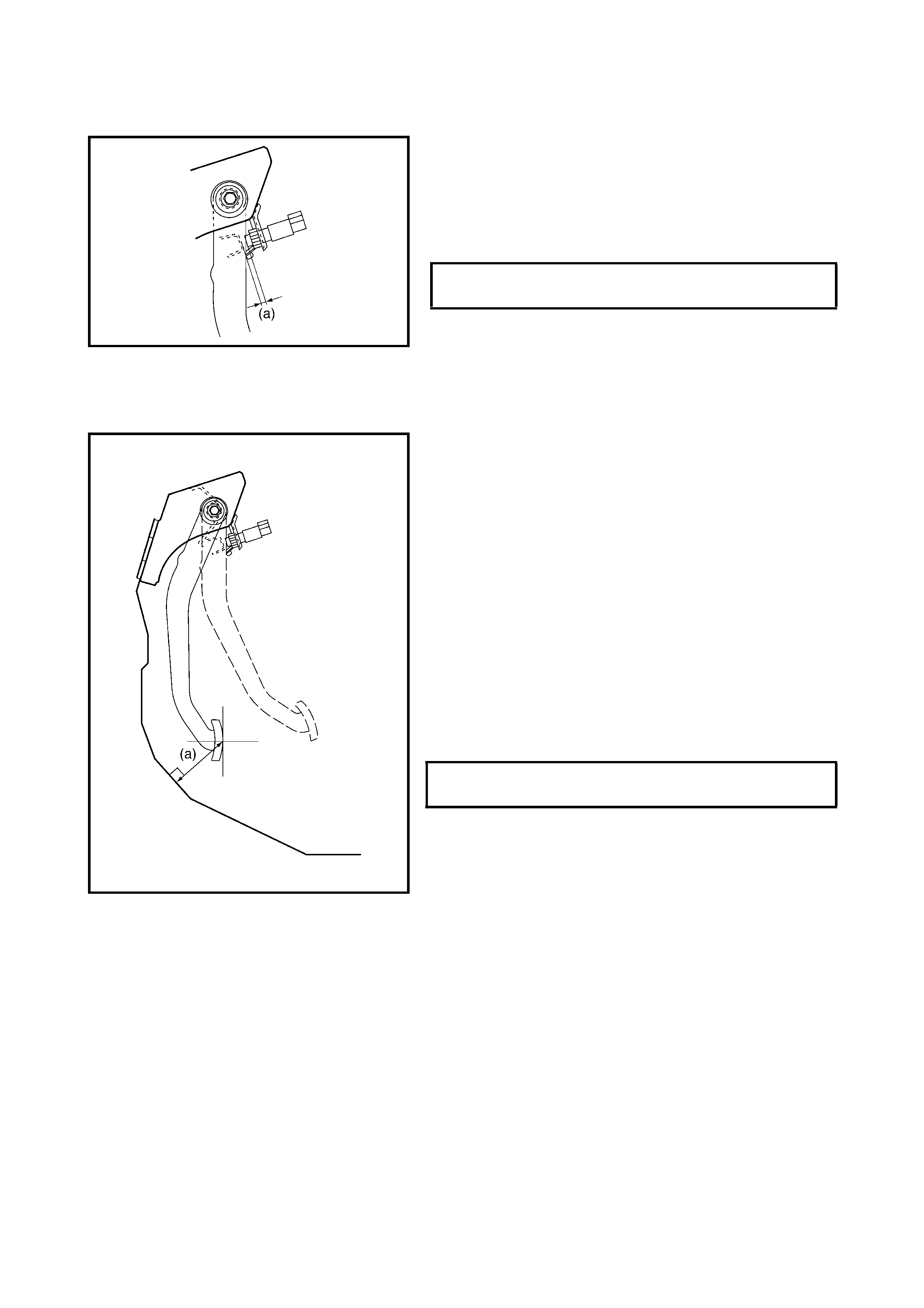
2.7 BRAKE LIGHT SWITCH ADJUSTMENT
Adjustment should be made as follows when installing
switch. Pull up brak e pedal toward y ou and while holding i t
there, adjust switch position so that clearance between end
of thread and brake pedal is as specified. Then adjust
brake light switch assembly position and lock it by turning
clockwise.
2.8 EXCESSIVE PEDAL TRAVEL INSP ECTION
1. Start engine.
2. Depress brake pedal a few times.
3. With brake pedal depressed with approximately 300
Nm (30 kg) load, measure brake pedal to wall (dash
panel silencer) clearance (a).
If clearance (a) is less than specified, the most likely
cause is either the rear brake shoes are worn out
beyond their limit or there is air in the lines.
Should clearance (a) remain less than specification
even after repla ce men t of b ra ke sh oes an d bleed ing of
the system , other possib le but infrequen t causes are a
malfunction of the rear brake shoe adjusters or the
booster push rod length is out of adjustment.
Bleed brake system. Refer to 3.1 AIR BLEEDING OF
BRAKE SYSTEM in this Section.
Remove brake drums for adjuster inspection (Refer to
3.3 REAR BRAKE in this Sec tion). If defective, correct
or replace.
2.9 BRAKE DISC INSPECTION
Inspect brake discs, refer to 3.2 FRONT BRAKE in this
Section for inspection points and procedure.
CLEARANCE BETWEEN BRAKE
PEDAL AND BRAKE LIGHT SWITCH (a) 0.5 - 1.5 mm
CLEARANCE BETWEEN BRAKE PEDAL
AND DASH PANEL SILENCER (a) OVER 140 mm

2.10 PARKING BRAKE INSPECTION AND ADJUSTMENT
INSPECTION
Hold centre of parking brake lever grip and pull it up with
200 N (20 kg) force.
With the parking brake lever pulled up as shown, count
ratchet notches. There should be 4 to 9 notches.
Also, check if both right and left rear wheels are locked
firmly.
To count the number of no tc hes eas il y, li ste n to t he c lick ing
sounds from the ratchet while pulling the parking brake
lever (do not depress release button).
One clicking sound corresponds to one notch.
If the number of notches is out of specification, adjust the
cable referring to adjustment procedure below to obtain
specified parking brake operation.
NOTE: Check tooth tip of each notch for damage or wear.
If any damage or wear is found, replace the parking brake
lever.
ADJUSTMENT
NOTE: Make sure the following conditions before are met
before adjusting the parking bra ke cable.
• No air is trapped in brake system.
• The brake pedal travel is correct.
• The brake pe dal has been dep ressed a few times with
about 300 N (30 kg) load.
• The parking brake lever is pulled up a few times with
about 200 N (20 kg) load.
• The rear brake shoes are not worn beyond their limit,
and the self adjusting mechanism operates correctly.
After confirming that th e above conditions are all satisfied,
adjust t he parking brake lever stroke by loosening or tight-
ening the adjusting nut (1).
NOTE: Check brake drum for dragging after adjustment.
2.11 BOOSTER OPERATION INSPECTION
There are two ways to perform this inspection, with and
without a tester. Normally, it is possible to determine the
brake booster condition without using a tester.
NOTE: For this check, make sure there is no air in the
hydraulic lines.
CHECK AIR TIGHTNESS
1. Start engine.
2. Stop engine after running for 1 to 2 minutes.
PARKING BRAKE STROKE
(WHEN LEVER IS PULLED UP AT 200 N)
(20 kg) 4 TO 9
NOTCHES
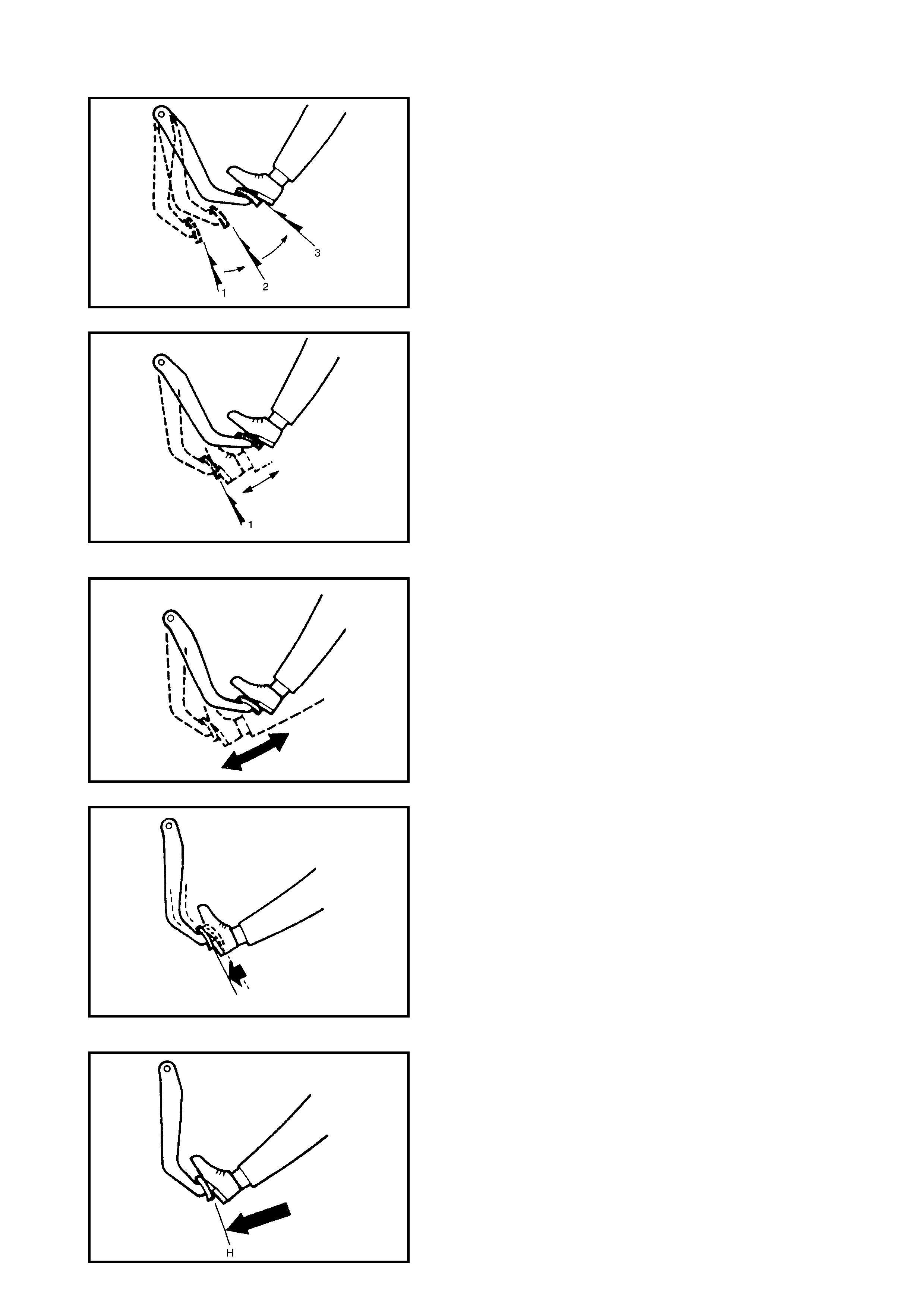
3. Depress the brake pedal several times with the same
load as in ordinary braking and observe the pedal
travel. If the pedal travel is long initially (1) but
decreases as the pedal is depressed for the second (2)
or more times (3), air tightness is obtained.
4. If the pedal travel doesn’t change, air tightness is not
obtained.
NOTE: If defective, inspect the vacuum lines and sealing
parts, correct any faults then repeat the entire test.
CHECK OPERATION
1. With the engine not running, depress the brake pedal
several times with the same load and make sure that
the pedal travel does not change.
2. Start the engine while depressing the brake pedal. If
the pedal travel increases slightly , operation is satisfac-
tory. No change in pedal travel indicates a malfunction.
CHECK AIR TIGHTNESS UNDER LOAD
1. With the engine running, depress the brake pedal. Stop
the engine while holding (H) the brake pedal
depressed.
2. Hold (H) the brake pedal depressed for 30 seconds
(T). If the pedal height does not change, the condition
of the booster is good. The pedal rising indicates a
malfunction.
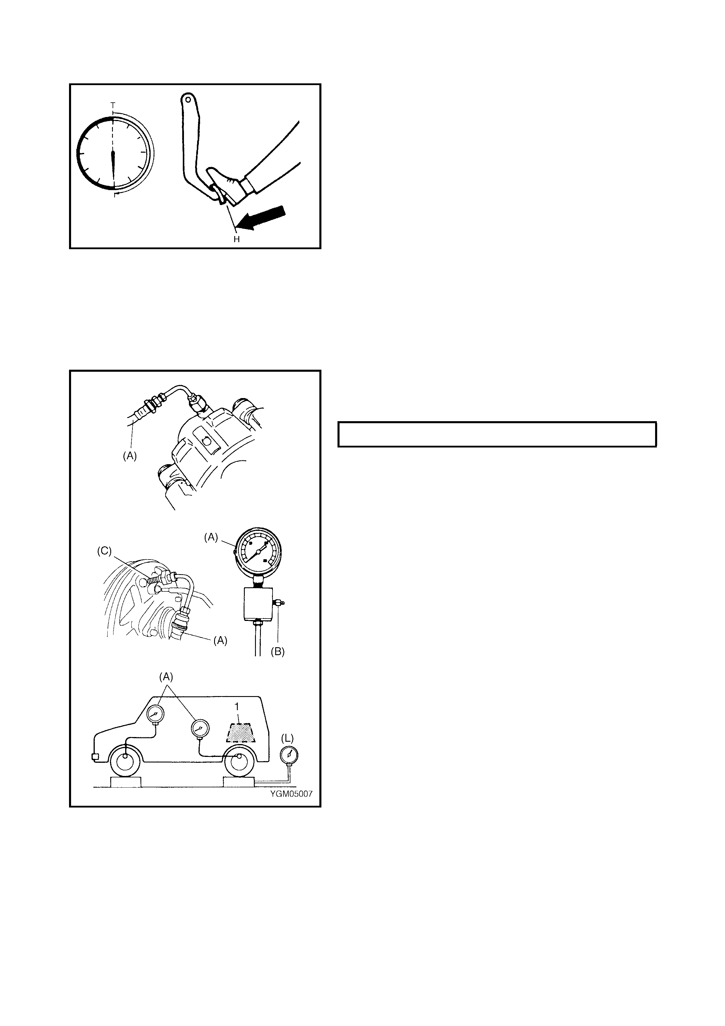
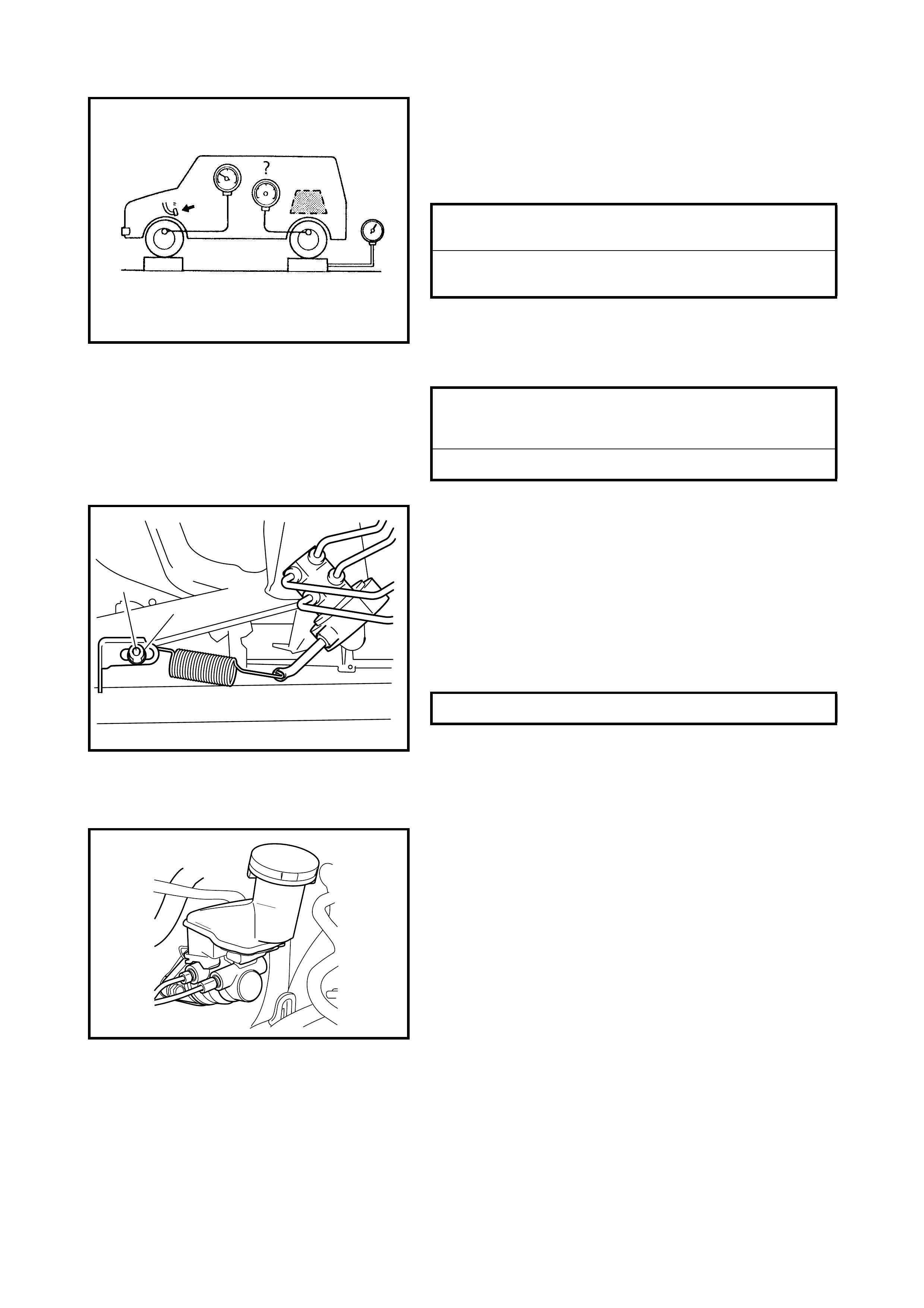
2.12 FLUID PRESSURE TEST (IF EQUIPPED WITH LSPV)
The test procedure for the LSPV assembly is as follows.
Before testing, confirm the following.
• The fuel tank full.
• Vehicle is equipped with spare tyre, tools, jack and jack
handle.
1. Posi tion the v ehicle on a level fl oor and place appr oxi-
mately 1,0 00 N (100 k g) weight ( 1) on rear hous ing so
that rear axle weighs 5000 N (500 kg).
2. Install spe ci al tools 099 56- 02 310 (A) , 554 73-82 030 (B)
(air ble ede r plug as a spare part) a nd 09 952 -36311 (C)
(rear only) to front and rear brakes.
NOTE: Pressure gauge should be connected to bleeder
plug hole of front (left side brake) and rear (right side
brake).
After testing front left side and rear right side, test front right
side and rear left side in the same way
.
REAR AXLE WEIGHT (L) 5000 N (500 kg)
3. Depress the brake pedal gradually until the fluid
pressure of the front brake reaches specification as
indicated below then check the corresponding
pressure of the rear brake. It should be within the spec-
ification given below.
4. As above, apply 100 kg/cm
2
pressure to the front brake
and check that the rear brake pressure is within the
specification below.
5. If the rear brake pressure is not within specification,
adjust it by altering the position of bolt (2) as follows.
• If the rear brake pressure is higher than specification,
move the bolt ( 2) towards the centre of the ve hicl e. If it
is lower, towards the outside of the vehicle.
• Repeat Steps 3 and 4 until the rear brake pressure is
within sp ec ifica t io n.
• After adjustm ent , be s ur e to torque nut ( 1) to spe ci fic a-
tion.
6. Upon completion of the fluid pressure test, bleed the
brake system and perform brake test.
2.13 MASTER CYLINDE R AND BRAKE FLUID LEVEL INSPECTION
CAUTION: Do not use shock absorber fluid or any
other fluid which contains mineral oil. Do not use a
cont ai ner which ha s been used for mineral oil or a co n-
tainer which is damp. Mineral oil will cause swelling
and distortion of rubber parts in the hydraulic brake
system and water mixed with brake fluid will lower the
fluids boiling point. Keep all fluid containers capped to
prevent contamination.
1. Check the master cylinder and reservoir tank for
cracks, damage and brake fluid leakage. If any faults
exists, correc t or repla ce .
2. Check that the brake fluid level is between MAX and
MIN marks on reservoir tank.
NOTE: Be sure to use specified brake fluid either as indi-
cated on reservoir cap or recommended in the vehicles
owner’s manual. Use of any other fluid is strictly prohibited.
Fluid level should be bet ween MIN and MAX lines marked
on reserv oir.
If the brake warning lamp lights up during driving, replenish
fluid to MAX level.
LSPV SPECIFICATION
FRONT BRAKE 7500 kPa
LSPV SPECIFICATION
REAR BRAKE 4700 - 6900 kPa
LSPV SPECIFICATION (APPLY 100 kg/
cm
2
PRESSURE TO FRONT BRAKE)
FRONT BRAKE 10000 kPa
REAR BRAKE 5400 - 7700 kPa
LSPV NUT (a) 25 Nm
2
1, (a)
MAX
MIN
If the fluid decreases quickly, inspect the brake system for
leaks. Repair leak poi nts and refill brake reser voir to s peci-
fied level.
2.14 BRAKE HOSE AND PIPE INSPECTION
HOSE
The brake hose assemblies should be checked for road
hazard damage, for cracks and chafing of outer cover, for
leaks an d blister s. A light and mirror may be neede d for an
adequate inspection. If any of above conditions are
observed on the brake hoses, they must be replaced.
PIPE
Inspect the pipe assemblies for damage, cracks, dents and
corrosion. If any defects are found they must be replaced.
3. ON-VEHICLE SERVICE
3.1 AIR BLEEDING OF BRAKE SYSTEM
CAUTION: Brake fluid is extremely damaging to paint.
If brake fl ui d is accidently spilled on pai nted surface it
must be cleaned immediately by flushing with water.
It is necessary to bleed the brake system whenever air may
have entered hydraulic brake system.
The hydraulic lines of the brake system are based on a
diagonal split system (A and B). When a brake pipe or hose
is disconnected at a wheel, bleeding of the system must be
performed at both ends of the line of the removed pipe or
hose. When any joint part of the master cylinder or other
joint part between the master cylinder and each brake
(wheel) is removed, the hydraulic brake system must be
bled at all 4 wheels.
NOTE: Perform the bleeding operation starting with the
wheel c ylin der fa r thes t from the mas ter cyli nd er the n a t th e
front caliper of the same brake line. Repeat the procedure
on the other brake line.
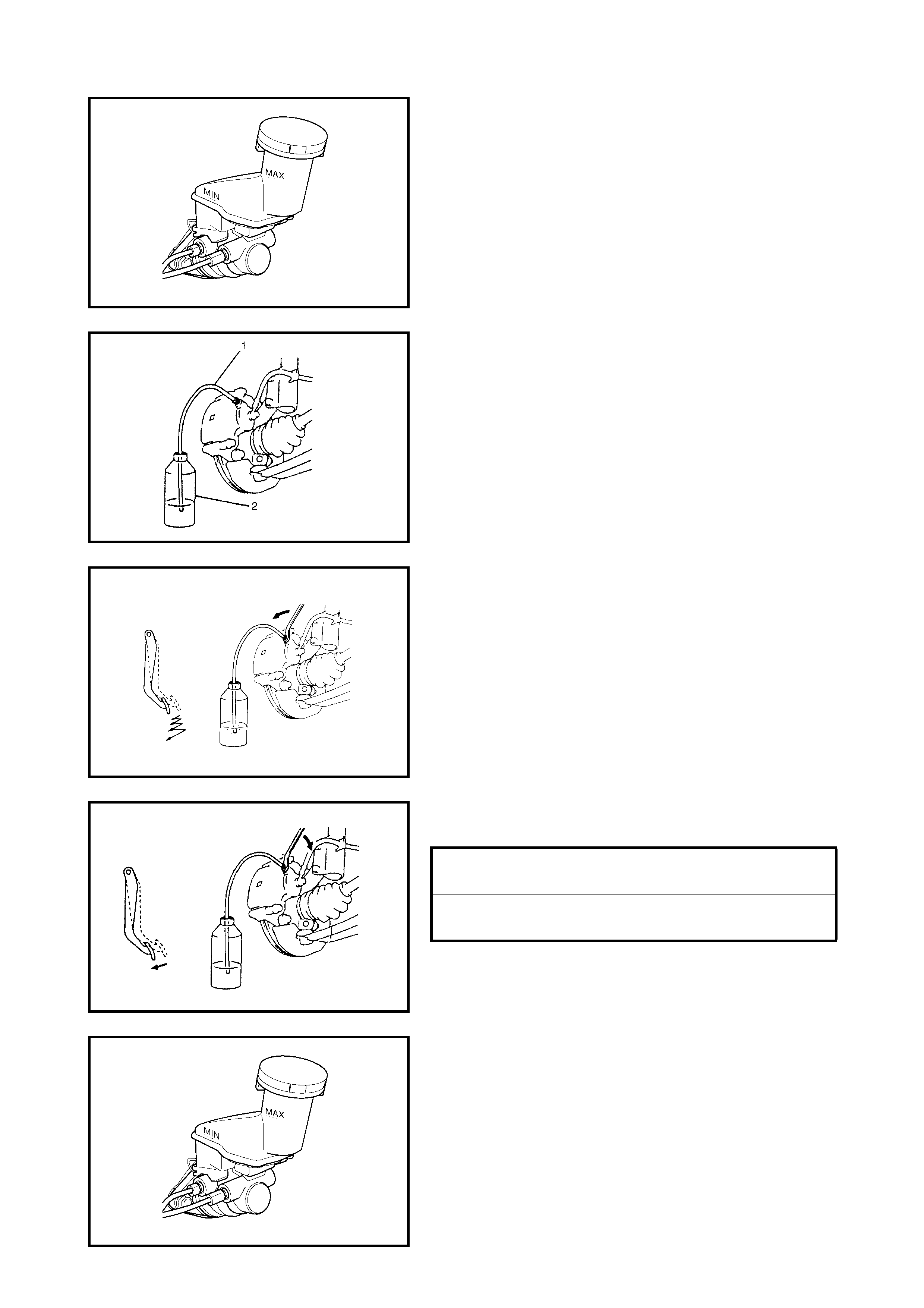
1. Fill the master cylinder reservoir with brake fluid and
ensure it remains at least half full during bleeding oper-
ation.
2. Remove the bleeder plug cap.
Attach a vinyl tube (1) to bleeder plug, and insert the
other end into container (2).
3. Depress the brake pedal several times, then while
holding it depressed, loosen the bleeder plug about
one-third to one-half a turn.
4. When the fluid pressure in the cylinder is almost
depleted, ret igh ten the ble ede r plug.
5. Repeat this procedure until there are no more air
bubbles in the hydraulic line.
6. When the appearance of bubbles cease, depress and
hold brake the pedal and tighten the bleede r plug.
7. Attach the bleede r plu g cap.
8. After completing the bleeding operation, apply fluid
pressure to the pipe line and check for leakage.
9. Replenish fluid in the reservoir to the specified level.
10. Check brake pedal for sponginess. If the pedal is
spongy, repeat bleedi ng proc edur e .
FRONT BLEEDER PLUG
TORQUE SPECIFICATION 11 Nm
REAR BLEEDER PLUG
TORQUE SPECIFICAT ION 8 Nm

3.2 FRONT BRAKE
Legend
BRAKE PAD REMOVAL
1. Loosen wheel nuts and with vehicle raised, remove
wheels.
2. Remove caliper pin bolts (1).
9
1
7
13
2
14
3
12 26 Nm
85 Nm
811 Nm
10
5
4
6
11
1. Brake caliper carrier 6. Cylinder boot
: A pply brake fluid. 13. Brake disc
2. Boot 14. Slide pin
: Apply lithium grease
3. Caliper 7. Brake pad
4. Disc brake piston
: Apply brake fluid 8. Bleeder plug Tightening torque
9. Bleeder plug cap Do not reuse.
5. Piston seal
: Apply brake fluid 10. Pad spring
11. Anti noise shim
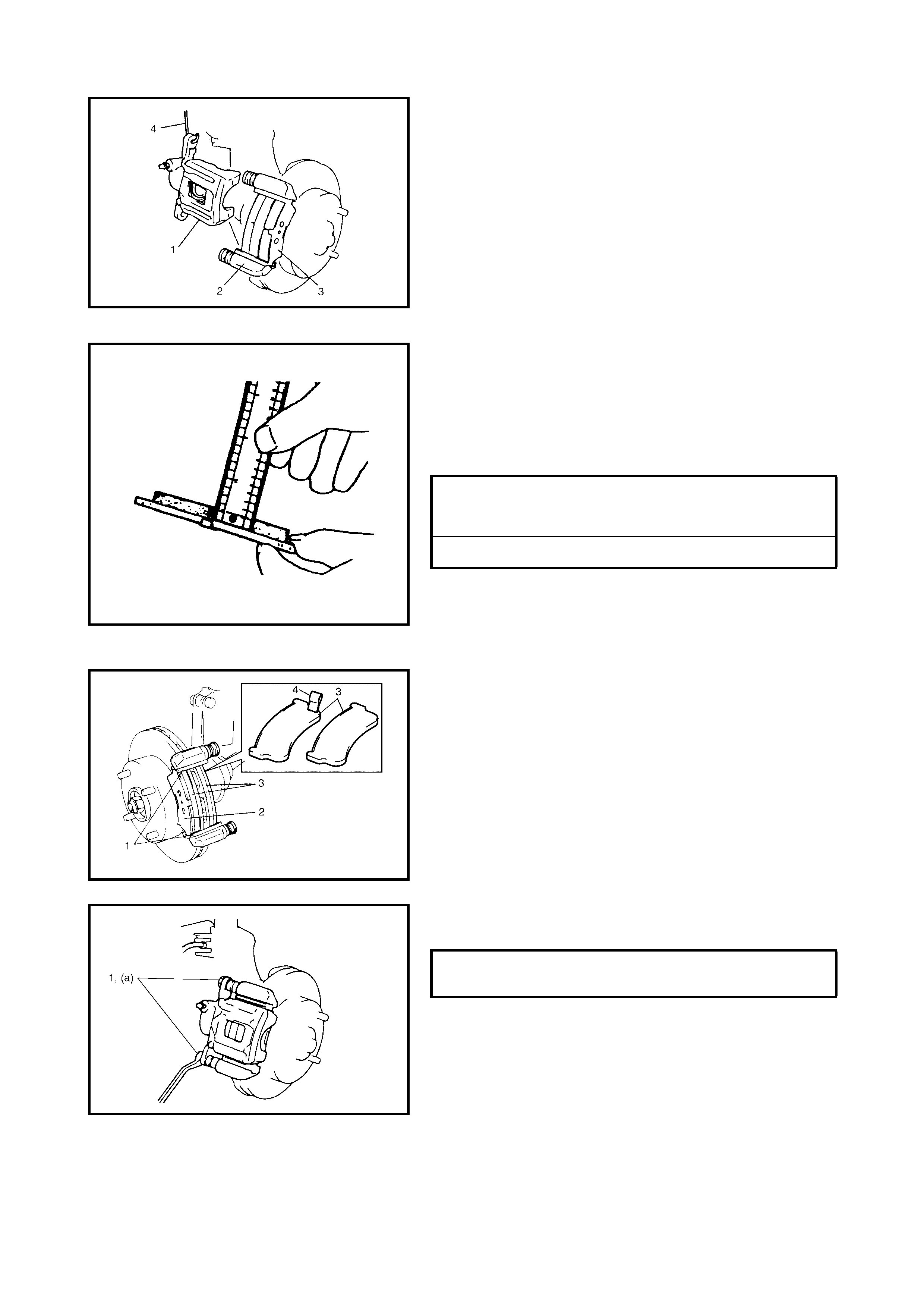
3. Remove caliper (1) from caliper carrier (2).
NOTE: Hang removed caliper (1) with a wire hook (4) or
similar to prevent brake hose from bending and twisting
excessively or being pulled.
Do not depress brake pedal with brake pads removed.
4. Remove brake pads (3).
INSPECTION
Check pad lining for wear. When wear exceeds limit,
replace with new ones.
CAUTION: Never polish brake pads with sandpaper. If
pad is polished with sandpaper, hard part icles of sand-
paper may be deposited in lining and could damage
brake disc. Always replace brake pads with new ones.
NOTE: When pads are removed, visually inspect caliper for
brake fluid leak. Rectify any leaks.
INSTALLATION
1. Fit brak e pad spri ng s (1) an d shi m (2) and ins tall brak e
pads (3).
NOTE: For the right side brake, install the pad with the
wear indicator (4) towards the centre of the vehicle.
2. Install the caliper and ti ghte n the ca li per pin bolts (1) to
specified torque.
3. Tighten wheel temporarily and lower vehicle.
BRAKE PAD THICKNESS
(LINING THICKNESS)
STANDARD 10 mm
LIMIT 1.0 mm
CALIPER PIN BOLT S (a)
TORQUE SPECIFICAT ION 26 Nm

4. Tighten wheel nuts to specified torque.
5. After completion of installation, check for brake effec-
tiveness.
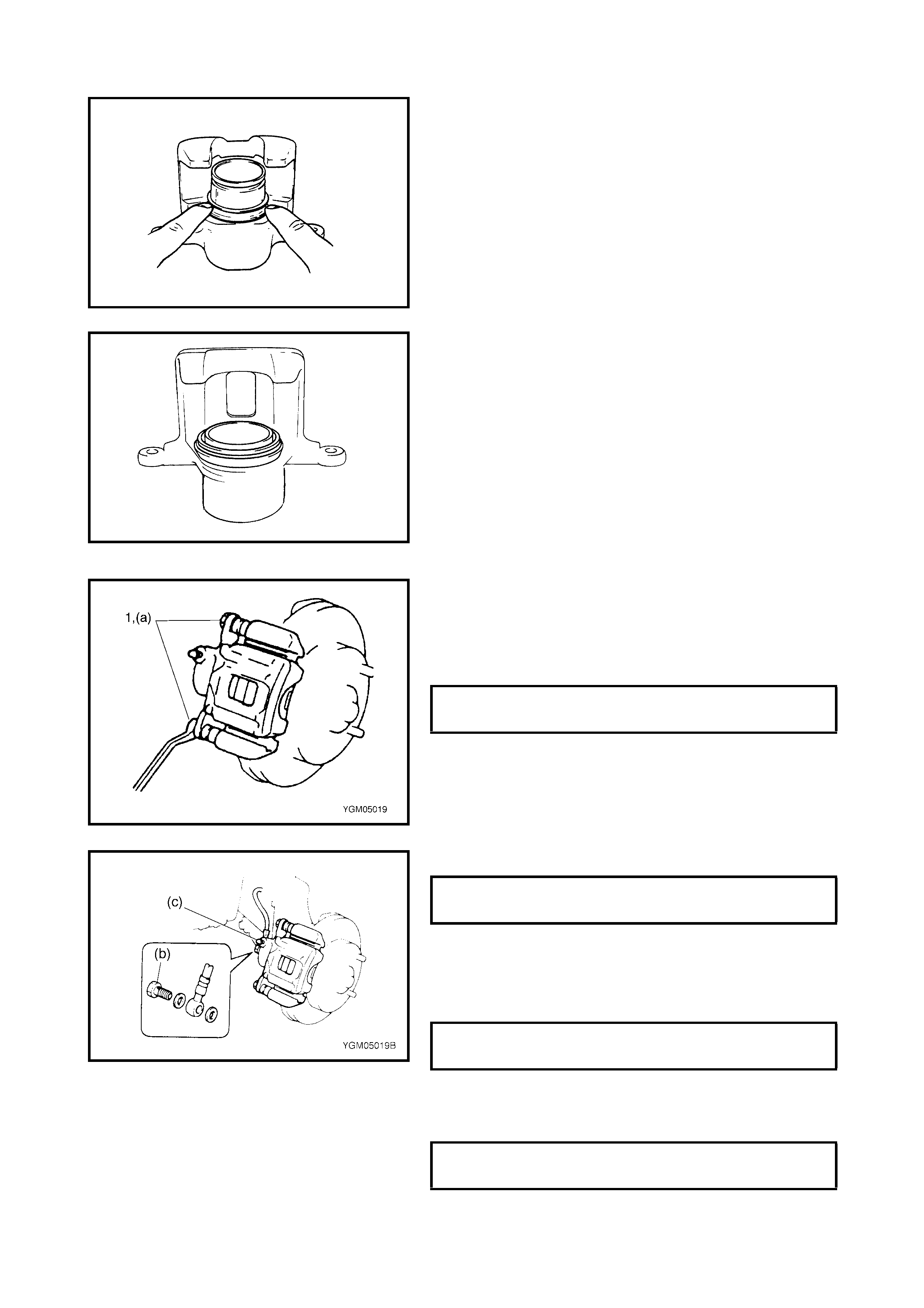
CALIPER ASSEMBLY REMOVAL
1. Place vehicle on hoist and remove wheel.
2. Remove E-ring (1).
3. Loosen flexible hose joint bolt (1) slightly at the caliper.
CAUTION: Be careful not to twist flexible hose while
loosening the bolt.
4. Remove the caliper pin bolts (1).
5. Remove the caliper from the caliper carrier.
6. Disconnect the flexible hose from the caliper taking
care not to twist it, as this will allow brake fluid to flow
out of the flexible hose. Have a container ready to
catch any spilt brake fluid.
WHEEL NUTS (a)
TORQUE SPECIFICATIONS 85 Nm

DISASSEMBLY
CAUTION: Clean around caliper with brake fluid before
disassembly.
1. Remove piston by blowing air into the flexible hose bolt
installation hole.
WARNING: Apply compressed air carefully to avoid
piston from jumping out of cylinder suddenly. Place a
cloth (1) as shown to avoid damage. The piston should
be removed gradually with moderately compressed air.
Do not place your fingers in front of piston when using
compressed air.
2. Remove cylinder boot (1).
CAUTION: Use care not to cause damage to cylinder
boot.
3. Remove piston seal using a thin blade such as a
thickness gauge, etc.
CAUTION: Be careful not to damage inside (bore side)
of cylinder.
4. Remove bleeder plug and cap from caliper.
INSPECTION
Pin Boot and Cylinder Boot
Check boots for breakage, cracks and damage.
If defective, replac e.
1
Piston Seal
Excessive or uneven wear of brake pads may indicate
uneven piston return. If so, replace rubber seal.
ASSEMBLY
Assem ble parts in rev erse orde r of di sassem bly, obse rving
the following instructions.
CAUTION:
• Wash each part thoroughly before installation
using the same fluid used in the master cylinder
reservoir.
• Never use any other fluid or thinners.
• Apply brake fluid to the piston seal before install-
ing them to the cylinder.
• After reassembling the brake lines, air bleed the
system.
• Install a new piston seal into the groove in the cyl-
inder securely making sure it is not twisted.
• Before installing the caliper to the carrier, apply
grease to the side pin a nd install it into the cali per
carrier hole. Check for smooth movement in the
thrust direction.
(A): Lithium Grease
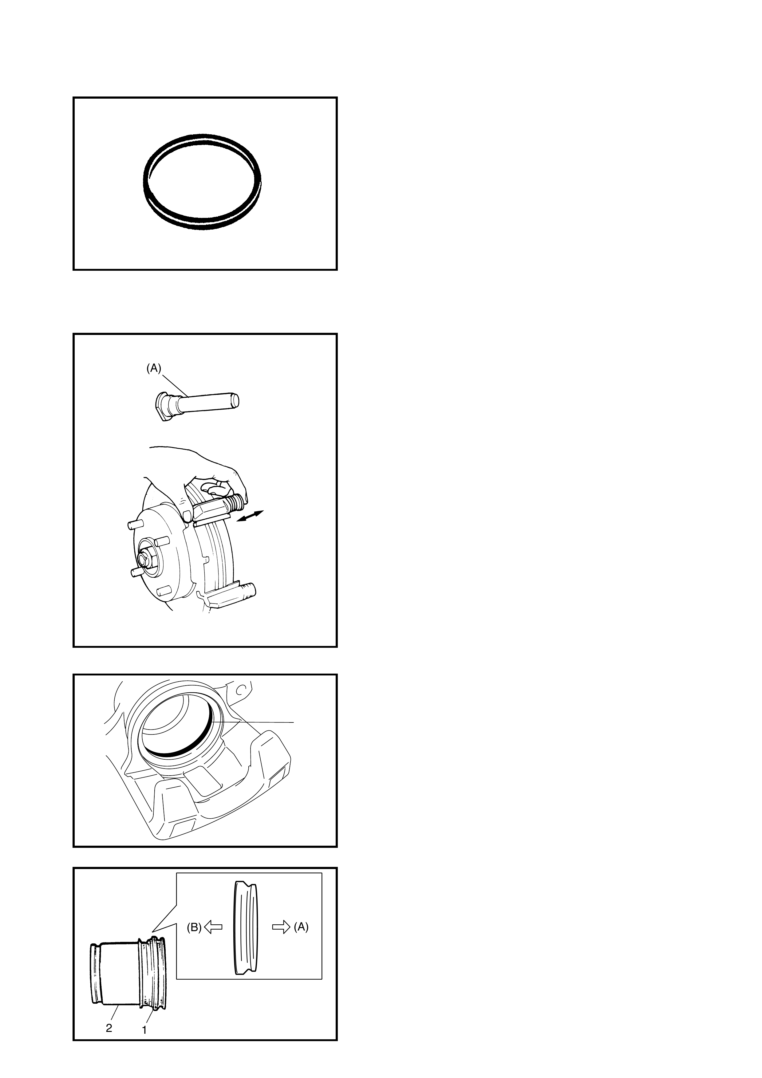
• Install piston seal to caliper referring to the following
instructions.
a. Use a new piston s eal at ever y overha ul. Fit pisto n
seal (1) into groove in cylinder taking care not to
twist it.
b. Before inserting piston (2) into cylinder, install new
boot (1) onto piston as shown.
(A): 1-grooved side towards cylinder
(B): 2-grooved side towards brake pad
1
a. Fit boot as shown in figure into boot groove in cylin-
der with fingers.
b. Insert piston into cylinder by hand and fit boot in
boot groove on piston.
NOTE: Check that the boot is fitted in the boot groove
securely all around the piston and cylinder.
INSTALLATION
1. Connect caliper to flexible hose.
2. Apply grease to slide pin, then install caliper to caliper
carrier.
3. Torque caliper pin bolts (1) to specification.
NOTE: Make sure that boots are fitted into groove securely.
4. Torque flexible hose joint bolt to specification.
WARNING: Make sure that flexible hose is not twisted
when tightening joint bolt. If it is twisted, reconnect it
taking care not to twist it.
5. Tighten bleeder plug to specified torque.
6. Install E-ring to strut securely.
7. Lowe r hoist.
8. Torque wheel nuts to specifications.
9. After completing installation, fill reservoir with brake
fluid and bleed air from brake system. Perform brake
test and check each installed part for oil leakage.
CALIPER PIN BOLT S (a)
TORQUE SPECIFICAT ION 26 Nm
FLEXIBLE HOSE JOINT BOLT (b)
TORQUE SPECIFICAT ION 23 Nm
BLEEDER PLUG (c)
TORQUE SPECIFICATION 11 Nm
WHEEL NUTS
TORQUE SPECIFICAT ION 85 Nm
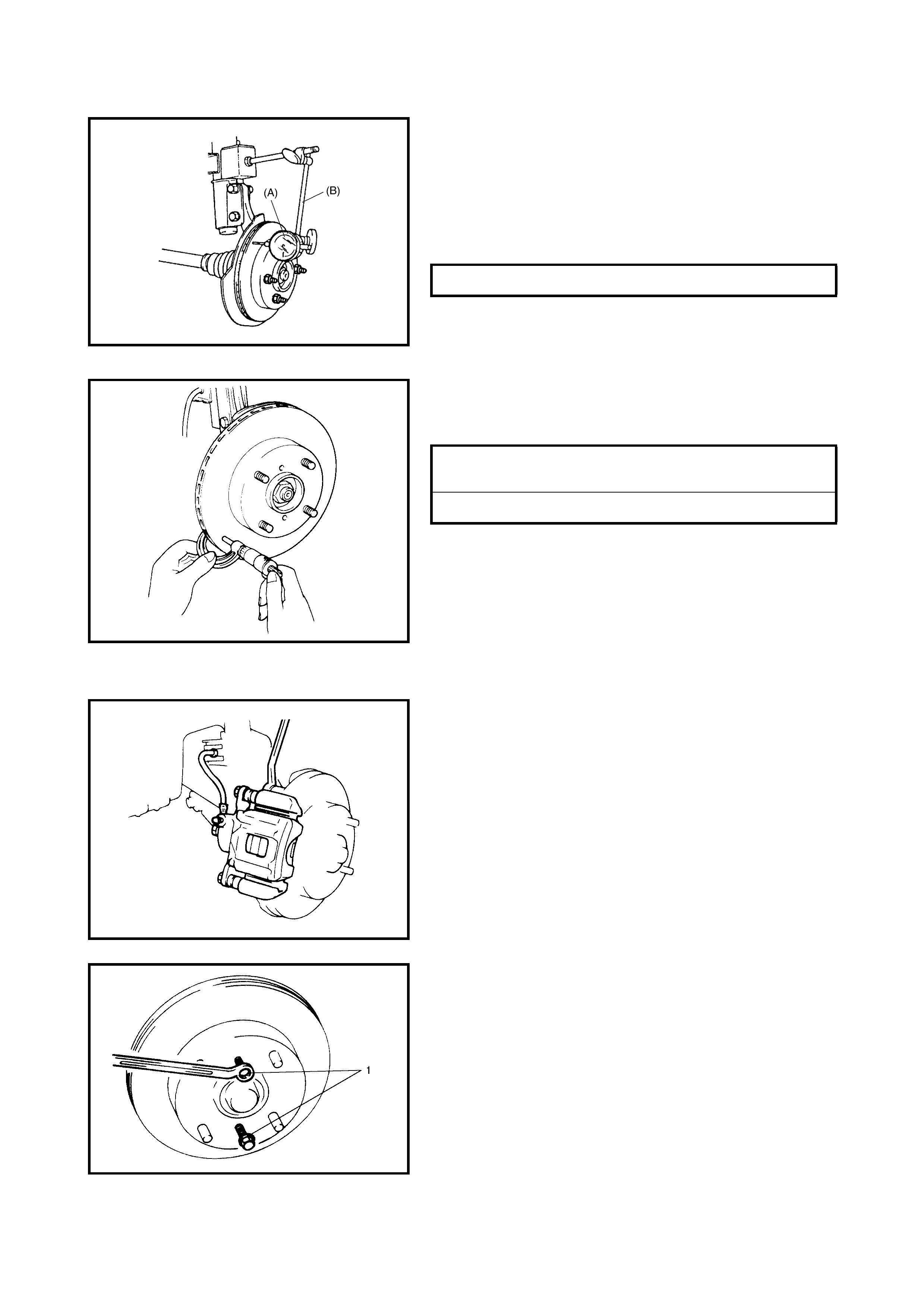
BRAKE DISC INSPECTION
• fit spacers and wheel nuts onto each wheel stud and
tighten securely.
• Using a magneti c stand, special too l 09900-20701 ( B),
and with dial gauge, special tool 09900-20606, posi-
tioned ab out 10 mm inward from the o uter edg e of the
disc, measure the discs deflection.
If the limit value is exceeded, correct or replace.
• Remove nuts and spacers.
• Using a micrometer, measure the thickness of the
brake disc.
If limit value is exceeded, replace brake disc.
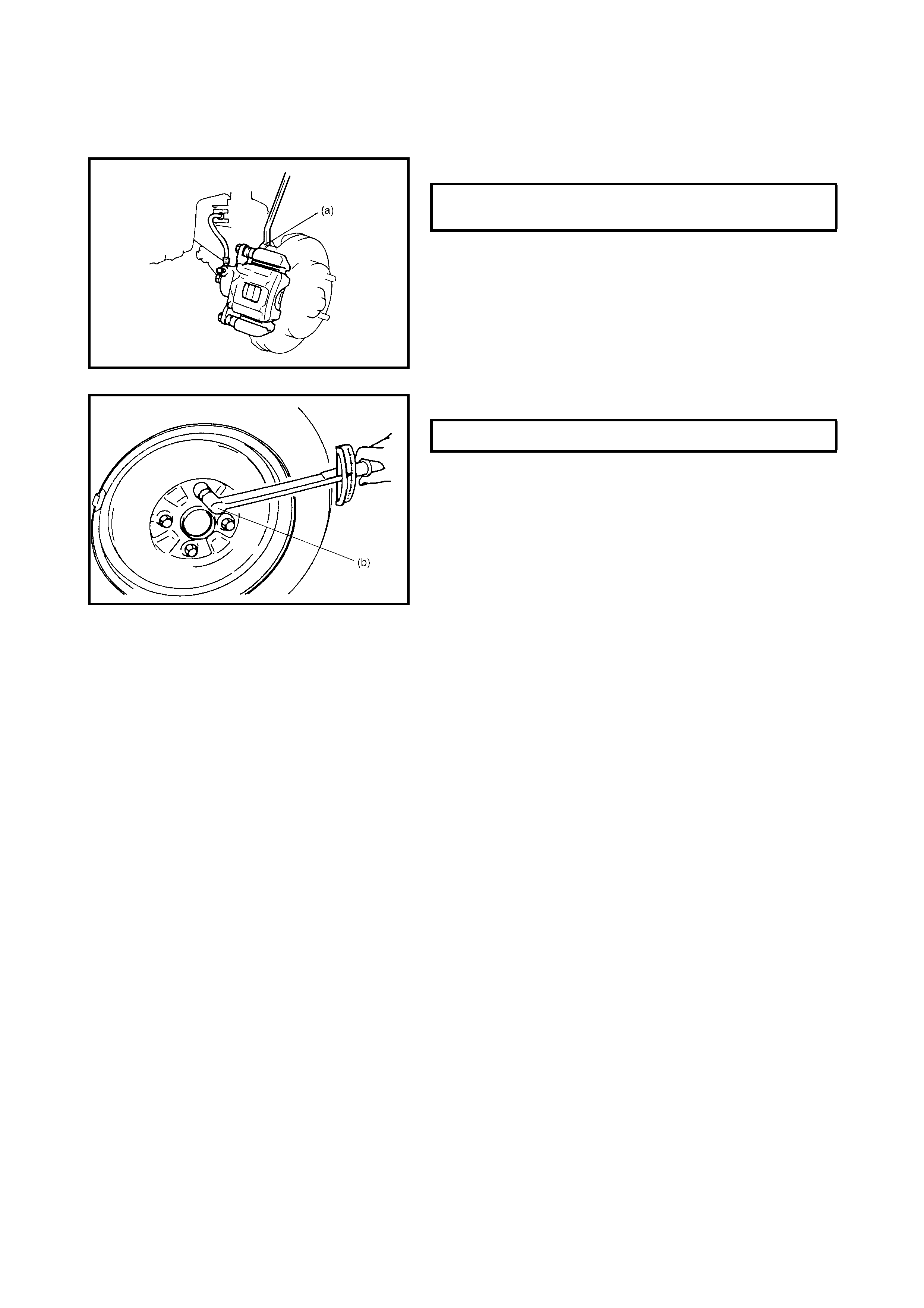
REMOVAL
1. Place vehicle on hoist and remove wheel.
2. Remove caliper assembly by removing the two caliper
carrier bolts.
CAUTION: During removal, be careful not to damage
brake flexible hose.
NOTE: Hang the removed cali per with a wire h ook or simi-
lar to prevent the brake hose from bending and twisting
excessively or being pulled.
Do not depress the brake pedal with the brake pads
removed.
3. Pull the brake disc off using two 8 mm bolts (1) as
shown in the figure.
DISC DEFLECTION LIMIT 0.10 mm MAX.
BRAKE DISC THICKNESS
STANDARD 17.0 mm
LIMIT 15.0 mm
INSTALLATION
1. Install the brake disc to the wheel hub.
2. Install the caliper assembly to the steering knuckle.
3. Torque the caliper carrier bolts to specification.
4. Torque front wheel nuts to specification.
5. Upon completion of installation, perform brake test,
refer to 2.1 ROAD TESTING BRAKES in this Section.
CALIPER CARRIER BOLTS (a)
TORQUE SPECIFICAT ION 85 Nm
WHEEL NUTS (b) 85 Nm
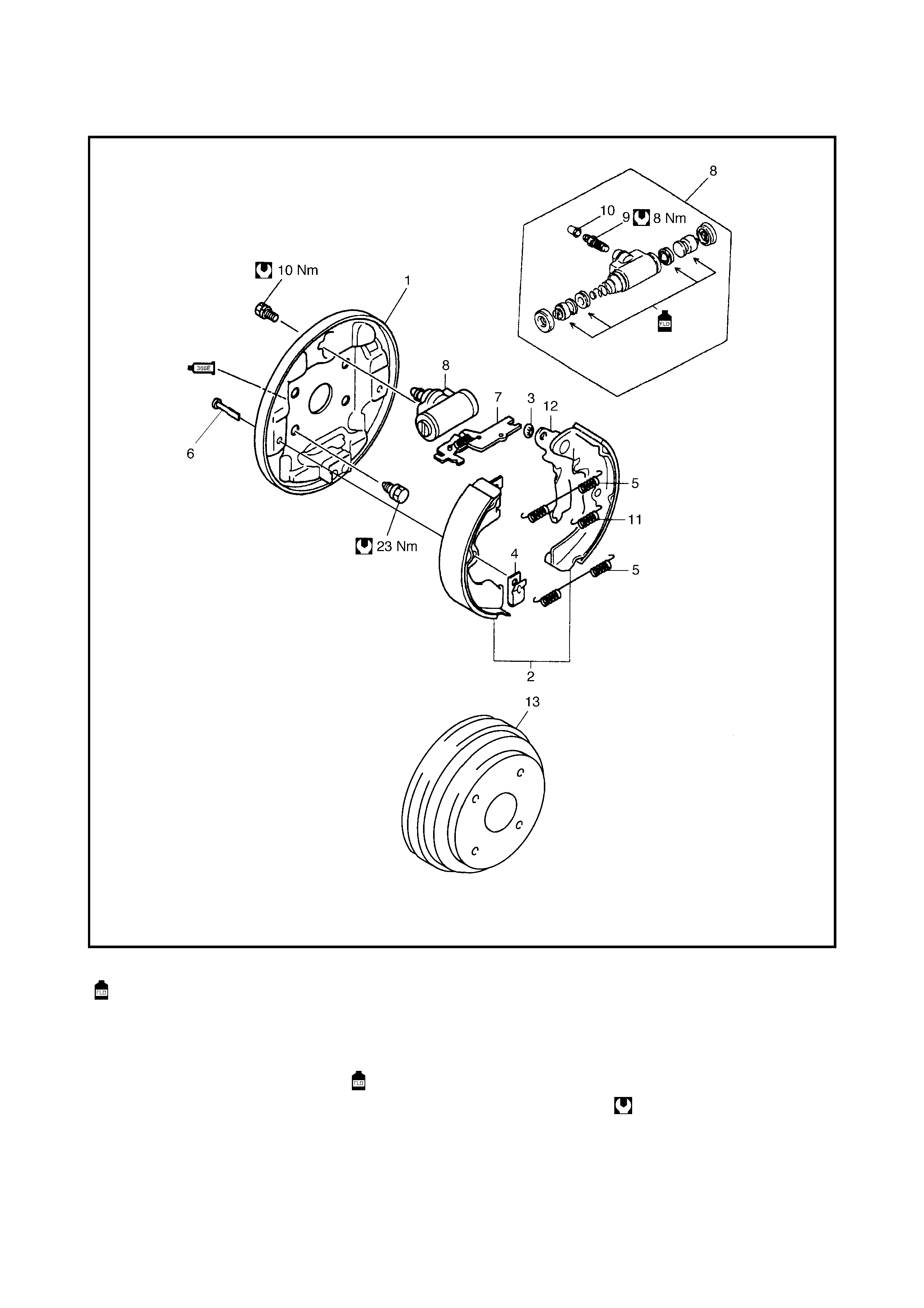
3.3 REAR BRAKE
Legend
1. Brake back plate
: Apply water tight sealant -
sealing compound 366E to
joint seam of brake back
plate and rear axle
4. Shoe hold down spring 9. Bleeder plug
5. Shoe return upper spring 10. Bleeder plug cap
6. Shoe hold down pin 11. Parking lever spring
7. Brake strut 12. Parking Brake Shoe Lever
8. Wheel cylinder
: Apply brake fluid to
piston cup
13. Brake Drum
2. Brake shoe Tightening torque
3. Push nut
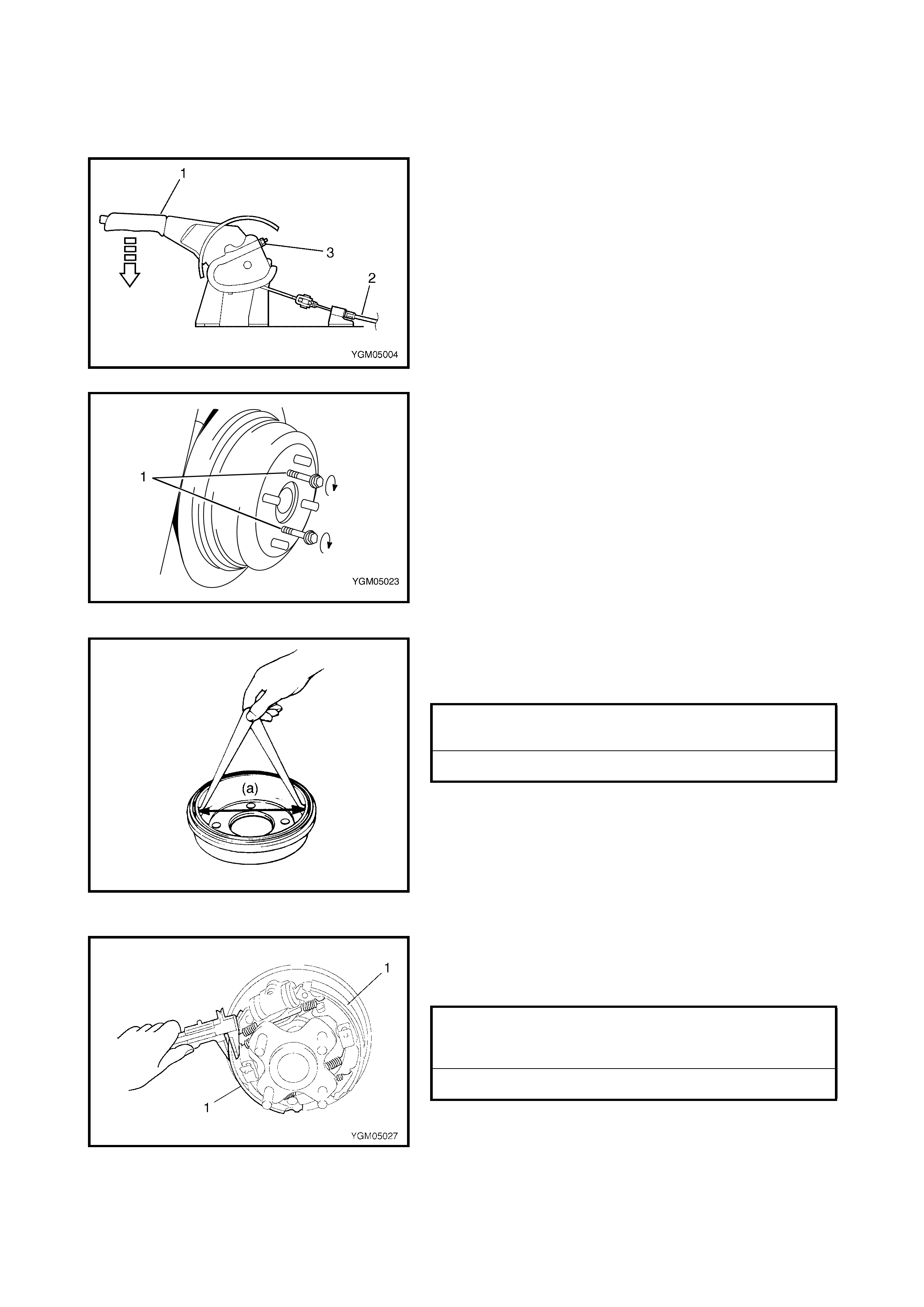
BRAKE DRUM REMOVAL
1. Place vehicle on hoist and remove wheel.
2. Release parking brake lever (1).
3. If required, remove console box and loosen adjusting
nut (3) for parking brake cable (2).
4. Pull brake drum off using two 8 mm bolts (1).
INSPECTION - BRAKE DRUM
Inspect brake drum for wear.
If limit v alu e o f dr um i nner d iam ete r is ex ceeded or un eve n
or stepped wear is excessive, replace drum.
NOTE: When drum i s removed, visua lly inspect wh eel cyl-
inder for brake fluid leakage. Rectify any leaks.
INSPECTION - BRAKE SHOE
Measure thickness of brake shoe (1) (including shoe
rim). Also, check surface of lining for hardening, exces-
sive wear and oil.
If one of the br ak e linings wear ex ce eds the limi t, al l lini ngs
must be replaced.
CAUTION: Never polish lining with sandpaper. If lining
is polished with sandpaper, hard particles of sandpa-
per may be deposited in lining and could damage
drum. Always replace brake linings with new ones.
DRUM INNER DIAMETER
STANDARD 180 mm
LIMIT 182 mm
BRAKE SHOE THICKNESS
(L INING AND SHO E)
STANDARD 5.5 mm
LIMIT 2.6 mm
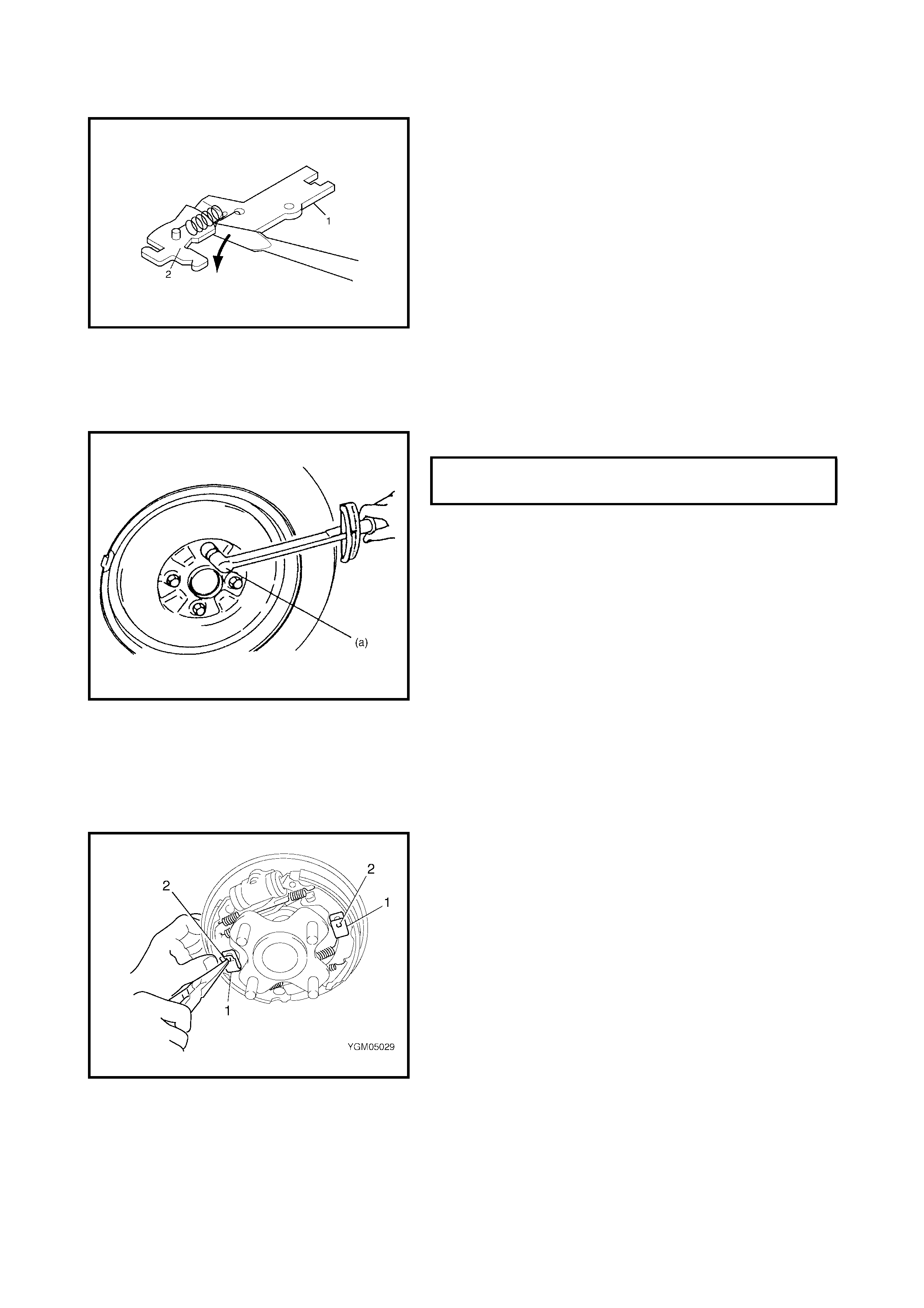
INSTALLATION
1. Place flat end rod or similar between rod (1) and
ratchet (2) and pull ratchet as shown to maximise
clearance between shoe and drum.
2. Install the br ake drum after making sur e that the ins ide
of the brake drum and the brake shoes are free from
dirt and oil.
3. Tighten wheel nuts to specified torque.
4. Upon completion of all jobs, depress the brake pedal
with about 30 0 Nm (30 kg) load 3 to 5 times to obtain
proper drum-to-shoe clearance.
5. Inspect the parking brake adjustment. If required adjust
the parking brake cable, refer to 2.10 PARKING
BRAKE INSPECTION AND ADJUSTMENT in this
Section.
6. Check to make sure that the brake drum is free from
dragging and the braking system works correctly.
Remove the vehicle from the hoist and perform brake
test, refer to 2.1 ROAD TESTING BRAKES in this
Section.
BRAKE SHOE REMOVAL
1. Remove brake drum referring to 3.3 REAR BRAKE,
BRAKE DRUM in this Section.
2. Remove brake shoe hold down springs (1) by turning
shoe hold down pins (2).
3. Remove return springs, brake shoes and strut.
WHEEL NUTS (a)
TORQUE SPECIFICAT ION 85 Nm
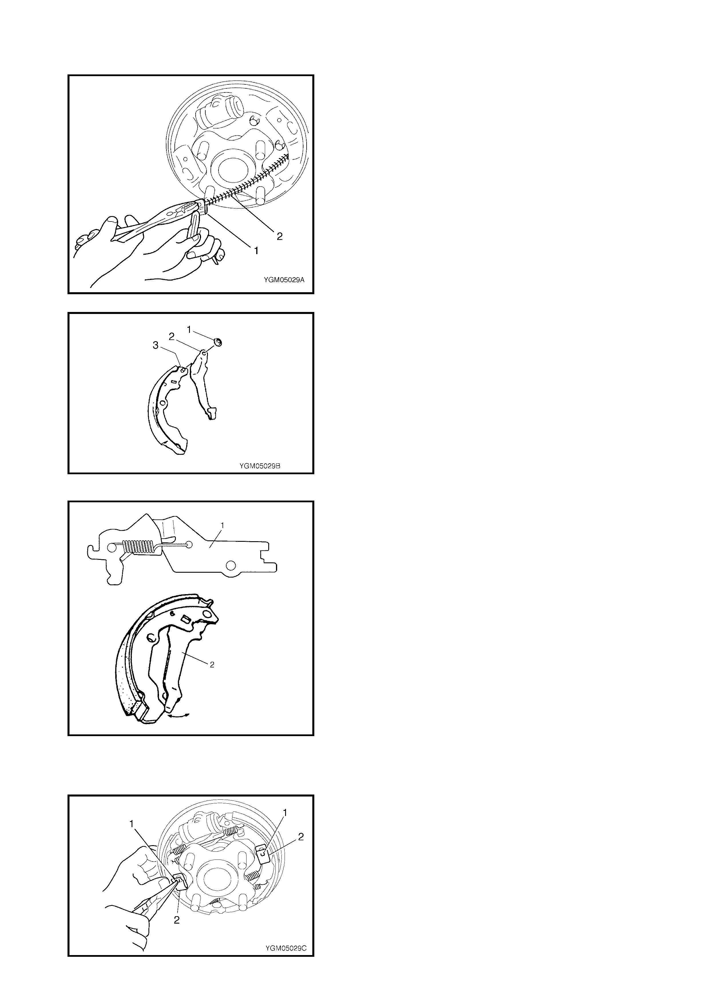
4. Disconnect parking brake shoe lever (1) from parking
brake cable (2).
5. Remove push nut (1).
6. Remove parking brake shoe lever (2) from shoe rim
(3).
INSPECTION
• Check ratchet of brake strut assembly (1) for wear or
damage. If found defective, replace.
• Check sh oe return s pring, str ut shoe r eturn spr ing and
shoe hold down spring for damage, corrosion and
weakening. If found defective, replace.
• Check for smooth movement of brake shoe lever (2)
along shoe rim. If found defective, replace.
CAUTION: Always use a new push nut.
INSTALLATION
Install parts in reverse order of removal, noting the follow-
ing.
• Install the brake shoe hold down springs (2) by pushing
them down in place and turning hold down pins (1).
• For procedure hereafter refer to 3.3 REAR BRAKE,
BRAKE DRUM in this Section.
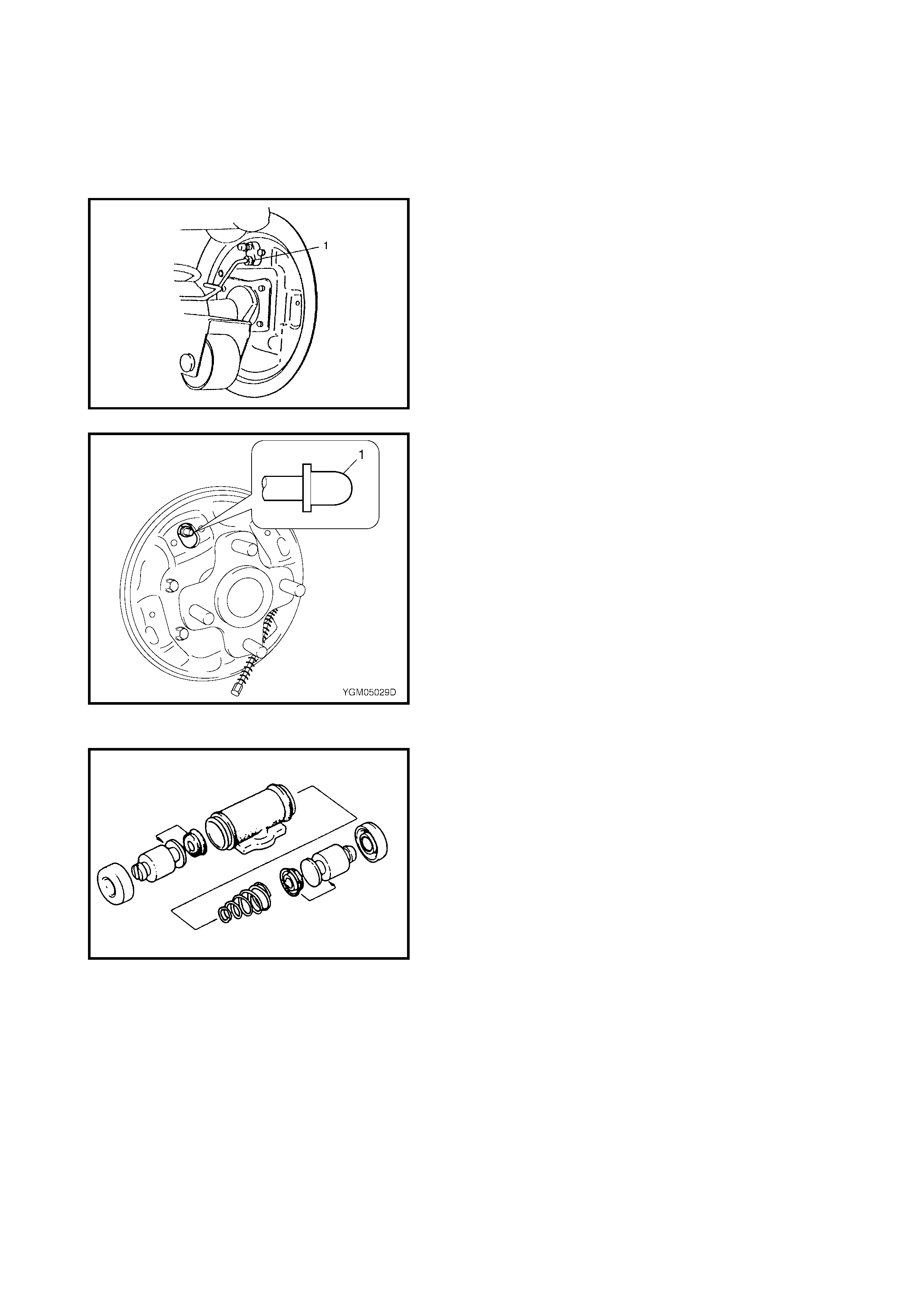
WHEEL CYLINDER REMOVAL
1. Remove brake drum refer to 3.3 REAR BRAKE,
BRAKE DRUM in this Section.
2. Remove brake shoes, refer to 3.3 REAR BRAKE,
BRAKE SHOE in this Section.
3. Loosen the brake pipe flare nut (1) but not enough to
allow brake fluid leakage.
4. Remove the wheel cylinder mounting bolts. Disconnect
the brake pipe from the wheel cylinder and put the
bleeder pl ug cap (1) onto th e pipe to pr event flui d from
spilling.
INSPECTION
Inspect the wheel cylinde r parts for wear, crack s, co rrosion
or damage. If defective replace.
NOTE: Clean wheel cylinder components with brake fluid.

INSTALLATION
1. Remo ve the blee der plug cap from the brake p ipe and
connect the pipe to the wheel cylinder (1) just enough
to prevent fluid from leaking.
2. Install the wheel cylinder (1) to the brake back plate (2)
to the specified torque.
3. Tighten the flare nut (3) of brake pipe to specified
torque.
4. Install the bleeder plug cap.
5. Install brake shoes. Refer to 3.3 REAR BRAKE,
BRAKE SHOE in this Section.
6. Install brake drum. Refer to 3.3 RE AR B R AK E, B RAKE
SHOE in this Section.
7. Fill the brake reservoir with brake fluid and bleed the
brake system. For bleeding operation refer to 3.1 AIR
BLEED ING OF BRAKE SYSTEM in this Section.
8. Upon completion of all jobs, depress brake pedal with
about 300 Nm (30 kg) load 3 to 5 times to obtain proper
drum-to-shoe clearance.
9. Inspect parking brake adjustment. If required adjust
parking brake cable, refer to 2.10 PARKING BRAKE
INSPECTION AND ADJUSTMENT in this Section.
10. Install wheel and tighten wheel nuts to specified
torque.
11. Check to ensure that the brake drum is free from
dragging and correct braking is obtained. Remove
vehicle from hoist and perform brake test (foot brake
and parking brake).
12) Check each installed part for oil le akage.
BRAKE BACK PLATE REMOVAL AND
INSTALLATION
Refer to Section 3E REAR SUSPENSION, 3.7 REAR
AXLE SHAFT AND WHEEL BEARING.
CYLINDER MOUNTING BOLTS (a)
TORQUE SPECIFICAT ION 10 Nm
REAR BRAKE PIPE FLARE NUT (b)
TORQUE SPECIFICAT ION 16 Nm
WHEEL NUTS
TORQUE SPECIFICAT ION 85 Nm
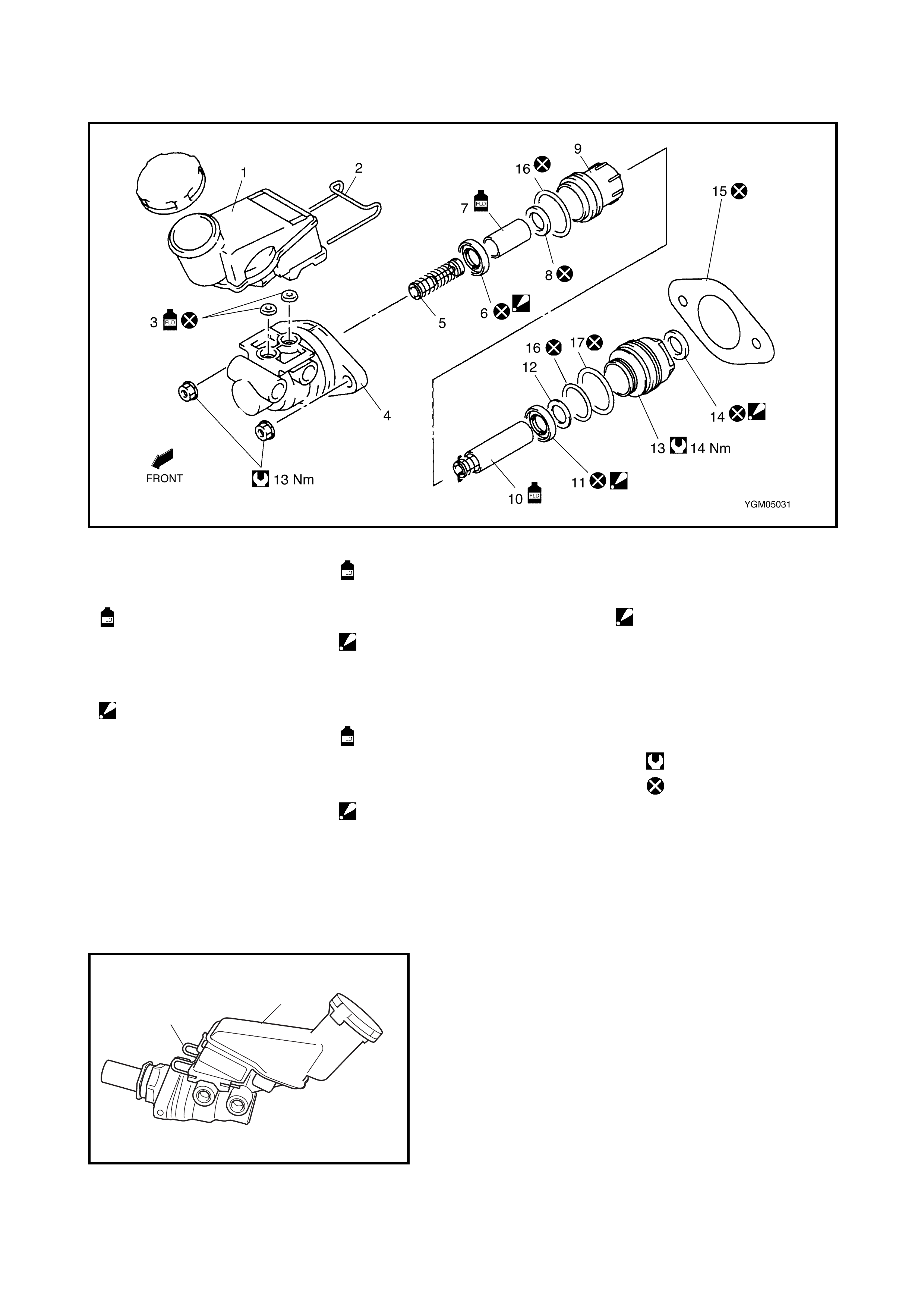
3.4 MASTER CYLINDER
Legend
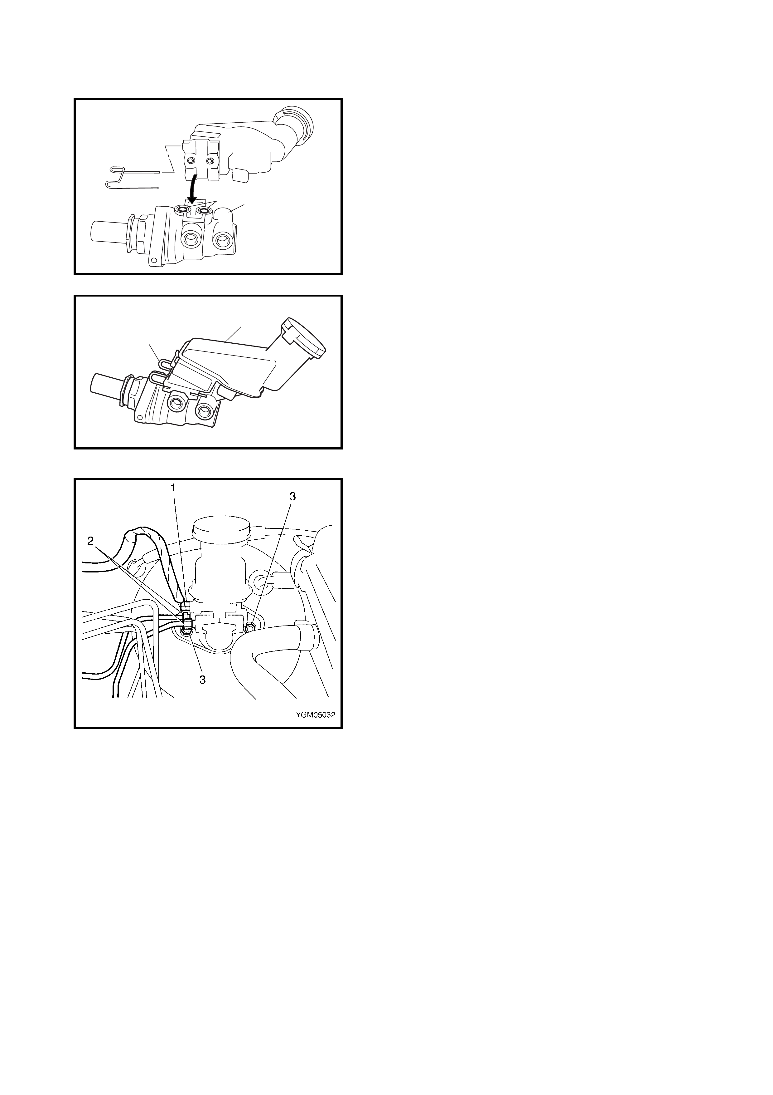
MASTER CYLINDER RESERVOIR REMOVAL
1. Remove master cylinder, refer to 3.4 MASTER
CYLINDER, MASTER CYLINDER ASSEMBLY
REMOVAL in this Section.
2. Pull out retainer (1) and remove reservoir (2).
1. Reservoir tank 7. Secondary piston 12. Cup spacer
2. Retainer : Apply brake fluid to 13. Cap
3. Grommet
: Apply brake fluid. contact surface of cup. 14. Cap cup
: Confirm installation
direction
8. Sleeve cup
: Confirm installation dir ec tion
: Apply brake fluid to
4. Master cylinder body
5. Secondary return spring 15. Master cylinder gasket
6. Secondary cup
: Con firm ins tallation
direction
9. Sleeve 16. O-ring (small)
10. Primary piston
: Apply brake fluid to
contact surface of cup.
17. O-ring (large)
Tigh teni ng torque
Do not reuse.
11. Primary cup
: Confirm installing direction
2
1
MASTER CYLINDER RESERVOIR INSTALLATION
1. Apply brake fluid to new grommets and attach
grommets (2) to master cylinder (1).
NOTE: Use new grommets.
2. Install reservoir (2) to the master cylinder and insert
retainer (1).
3. Install the master cylinder, refer to 3.4 MASTER
CYLINDER, MASTER CYLINDER ASSEMBLY
INSTALLATION in this Section.
4. Fill the reservoir with specified brake fluid up to MAX
mark.
5. After installation, bleed air from the system and check
for brake fluid leakage.
MASTER CYLINDER ASSEMBLY REMOVAL
1. Clean the outside of the master cylinder.
2. Drain the brake fluid in the reservoir.
3. Disconnect the fluid level switch connector (1) on the
reservoir.
4. Disconnect the brake pipes (2) connected to the
master cylinder.
CAUTION: Ensure brake fluid does not spill onto
painted surface or damage will occur. If fluid is spilt on
painted surface flush immediately with water.
5. Remove the master cylinder attaching nuts (3).
6. Remove the master cylinder and master cylinder
gasket.
1
2
2
1
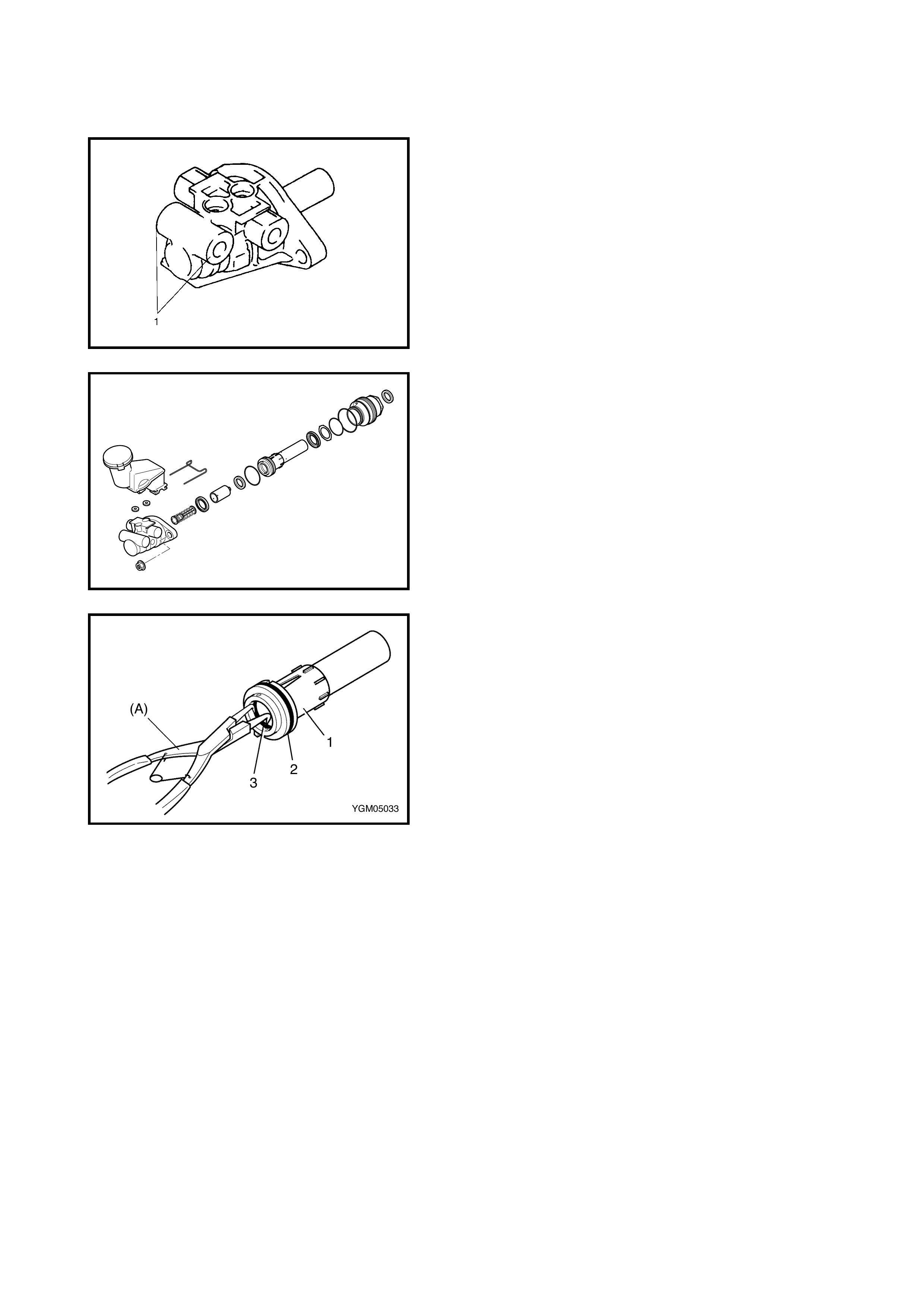
DISASSEMBLY
1. Loosen cap and remove it.
NOTE: For this procedure, apply a cloth to the outlet port at
the tip end (1) of the master cylinder body and secure cylin-
der using soft jawed vise.
2. Remove component parts from master cylinder body.
3. Remove sleeve cup (3) and O-ring (2) from sleeve (1)
using special tool 09900-06106 (A).
CAUTION: Take care not to damage the inside of the
sleeve. Replace if damaged.
INSPECTION
1. Check all disassembled parts for wear, damage,
corrosion and smooth operation.
If anything faulty is found, replace.
CAUTION:
• Wash disassembled parts with brake fluid.
•Do not reuse piston cups or O-rings.
2. Check screw hole i n master cy linder for wear or corro-
sion.
If anything faulty is found, replace.
CAUTION: Wash master cylinder with new brake fluid.
Do not use cloth to dry cylinder to avoid fibres being
attaching to the internal surface of the cylinder
.
ASSEMBLY
CAUTION:
• Never use any mineral oil such as kerosene oil or
petrol when washing and assembling pa rts.
• Check that the inside of cylinder (sleeve and cap),
wall, pistons and cup seals are free from any for-
eign objects such as dust and dirt. Take care not to
cause any damage to parts during assembly.
• Do not drop parts. Do not use any part which has
been dropped.
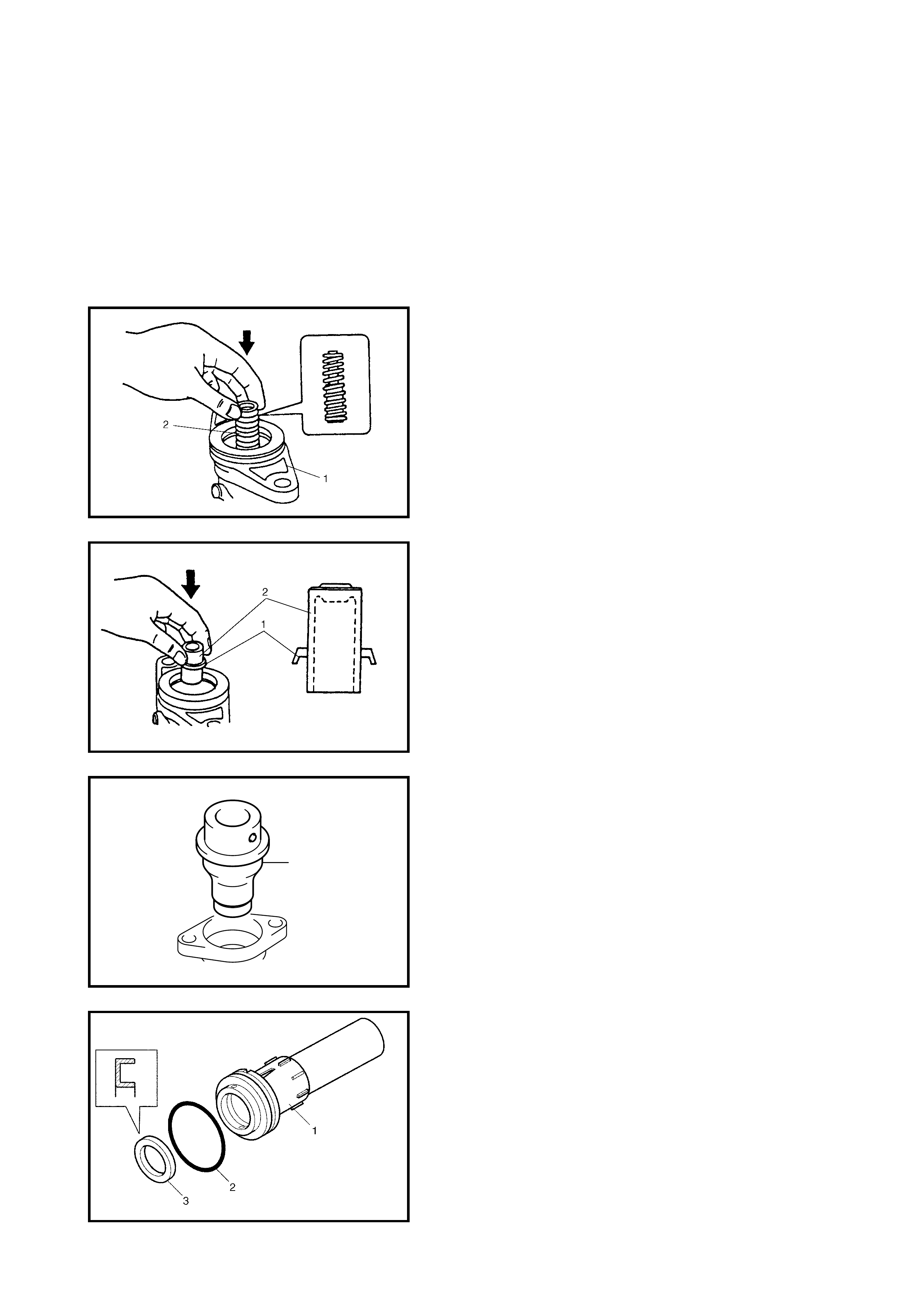
1. App ly br ake flu id to ins i de of cy linder (sl eev e a nd cap) ,
cups, O-rings and contact surface of piston assembly.
Install secondary return spring (2) to cylinder body (1)
noting spri ng direc ti on.
2. Fit the secondary cup (1) to the secondary piston (2),
and install in the cylinder in the direction shown.
NOTE:
• The secondary cup and the primary cup are the
same.
• The secondary cup diameter is larger than the
sleeve cup and cap cup.
3. Push the secondary cup to the bottom of the cylinder
using special tool 09951-18220 (A).
4. Install sl ee ve c up (3) an d O-r in g ( 2) t o sleev e ( 1) in the
direction shown.
NOTE:
• The diame ter of the slee ve cup and O -ring ar e smaller
than those of the cap.
• The sleeve O-ring is the same as the smaller cap O-
ring.
(A)
5. Install the sleeve assembly by aligning the protrusion
(1) on the sleeve with the dent (2) on the cylinder body.
6. Install the primary cup (1) and the spacer (2) in the
direction shown.
NOTE:
• The primary cup is the same as the secondary cup.
• The primary cup is larger than the cap cup and the
sleeve cup.
7. Remove the old cap cup (1) from the cap taking care
not to damage the inside of the cap (2).
8. Install the new cap cup (1) and the O-rings (3) to the
cap in the direction shown.
9. Install the cap and tighten it to the specified torque,
then confirm the length (A).
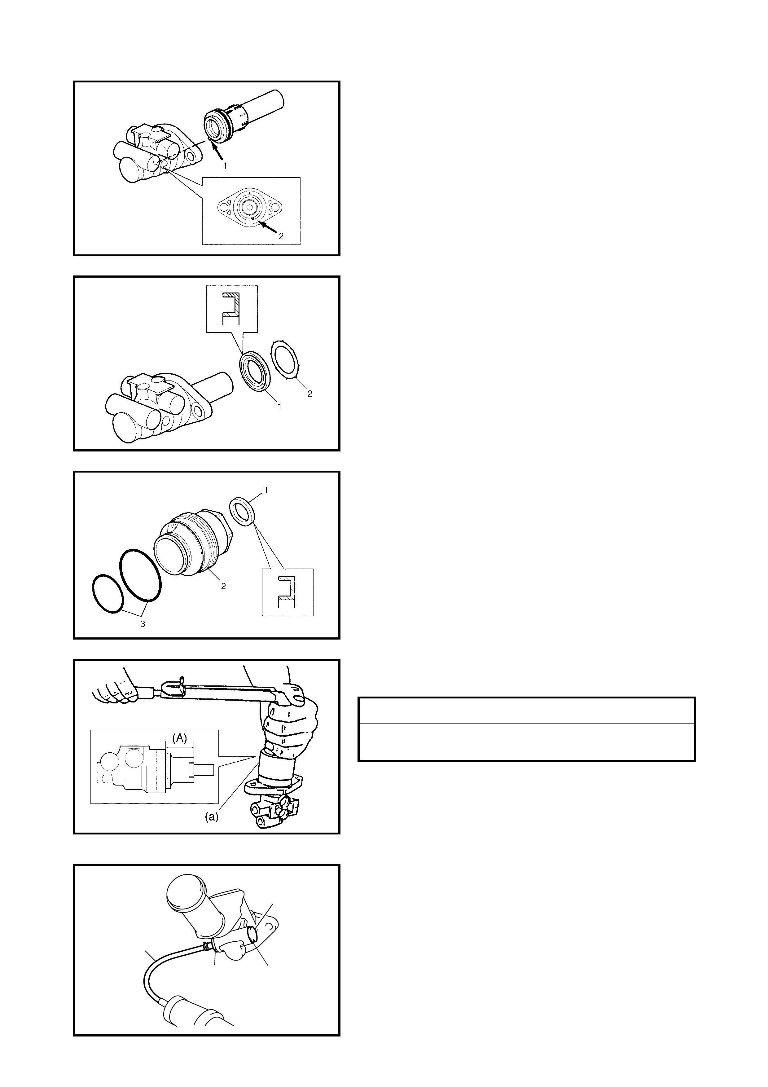
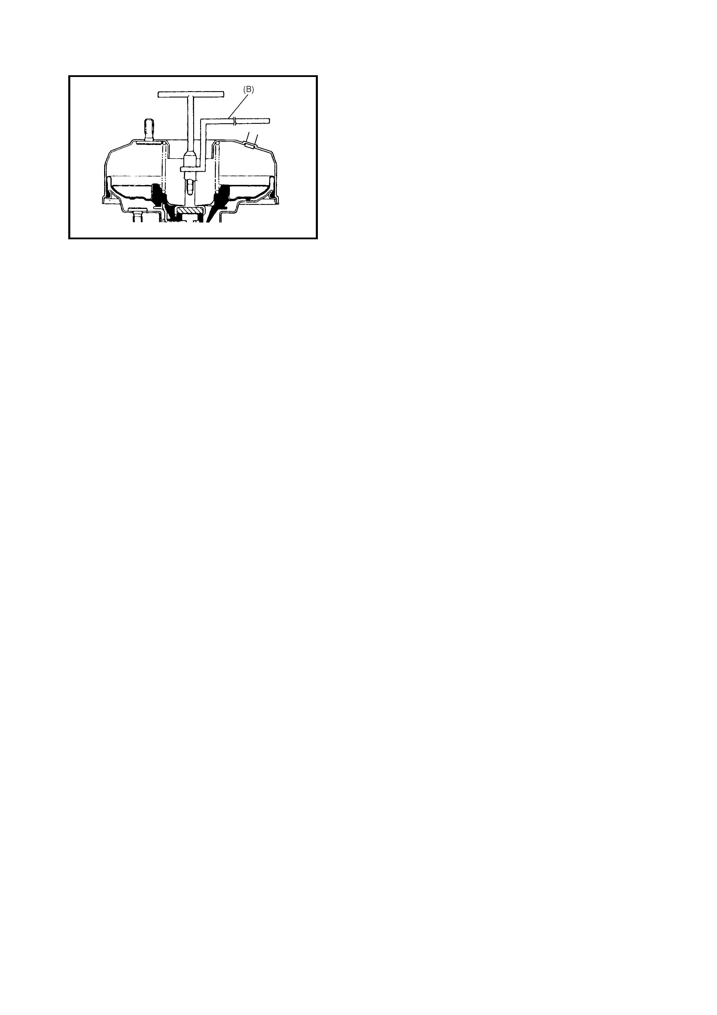
INSPECTION AFTER ASSEMBLY
1. Install radiator cap tester with special tool 09952-
46010 (A) to master cylinder port (1).
NOTE: For vehicles without ABS, install special tool 09952-
26020 (B) to opposite side port (2).
2. Apply air and confirm that pressure cannot be applied.
CAP TORQUE SPECIFICATION 14 Nm
CAP INSTALLATION POSITION (A) LESS THAN
26 mm
1
(B)
2
(A)
3. Set the master cylinder ( 1) in a vise (3) and a djust (A)
to the following.
4. Apply air with radiator cap tester, and confirm that 50
kPa pressure is applied.
5. Perform Steps 1 - 4 for port (2).
MASTER CYLINDER ASSEMBLY INSTALLATION
1. Install a new master cylinder gasket to the booster.
2. Install the master cylinder to the booster and tighten
master cylinder fixing nuts (3) to specified torque.
3. Connect brake pipes to master cylinder and tighten
flare nuts (2) to specified torque.
4. Connect fluid level switch connector (1) to reservoir.
5. Fill reservoir with specified brake fluid up to its MAX
mark.
6. Once completed, air bleed brake system, refer to
3.1 AIR BLEEDING OF BRAKE SYSTEM then check
brake pedal for play.
3.5 BRAK E BOOSTER
CAUTION: Never disassemble brake booster. Disas-
sembly will disturb factory se ttings. If brake booster is
found to be faulty, replace it with a new one.
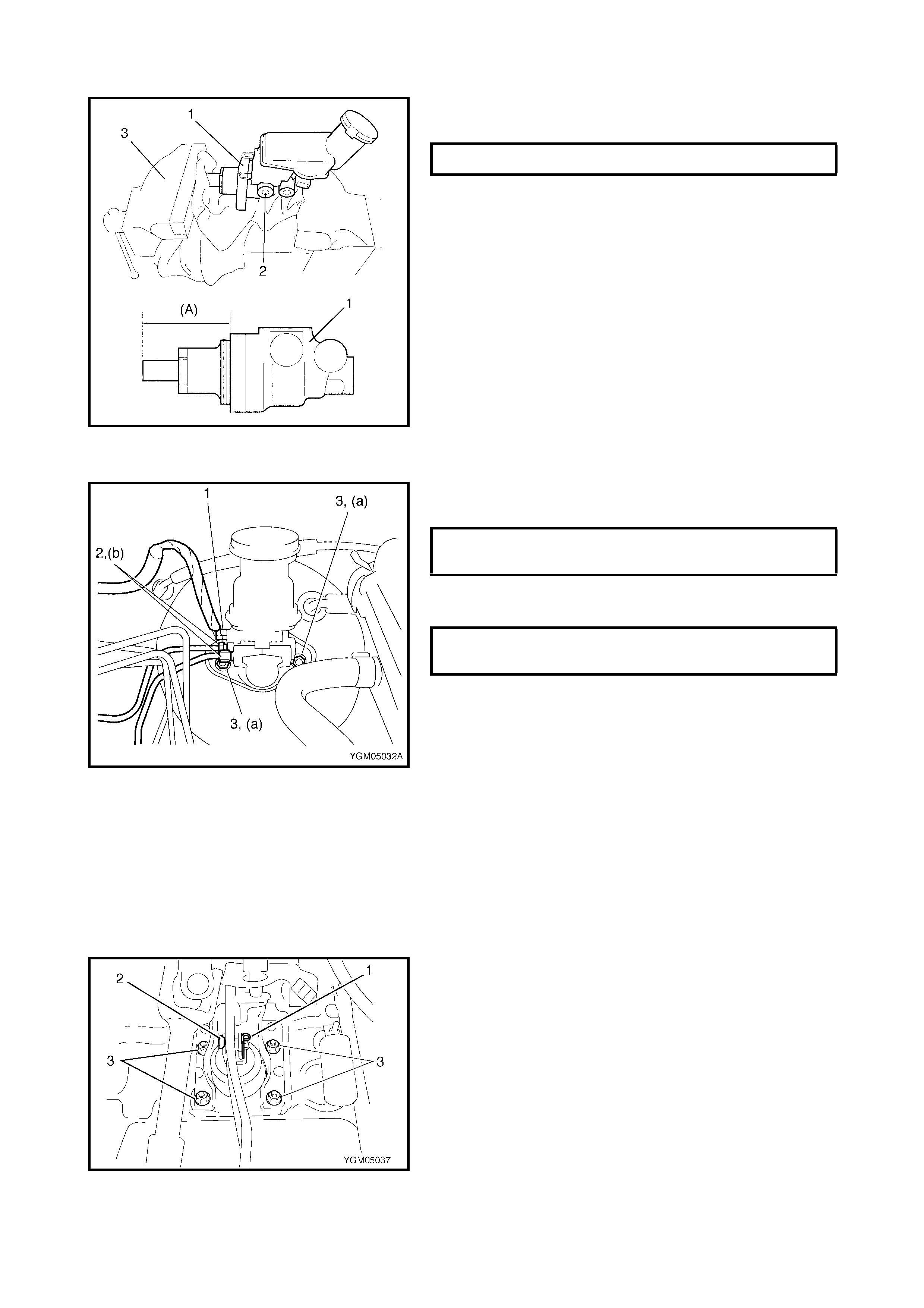
REMOVAL
1. Remove the master cylinder assembly from the
booster. Refer to 3.4 MASTER CYLINDER in this
Section.
2. Disconnect vacuum hose from booster.
3. Remove push rod clevis clip (1), pin (2) and brake
booster mounting nuts (3).
CAP ADJUSTMENT POSITION (A) 50 mm
MASTER CYLINDER FIXING NUTS (a)
TORQUE SPECIFICAT ION 13 Nm
BRAKE PIPE FLARE NUTS (b)
TORQUE SPECIFICAT ION 16 Nm
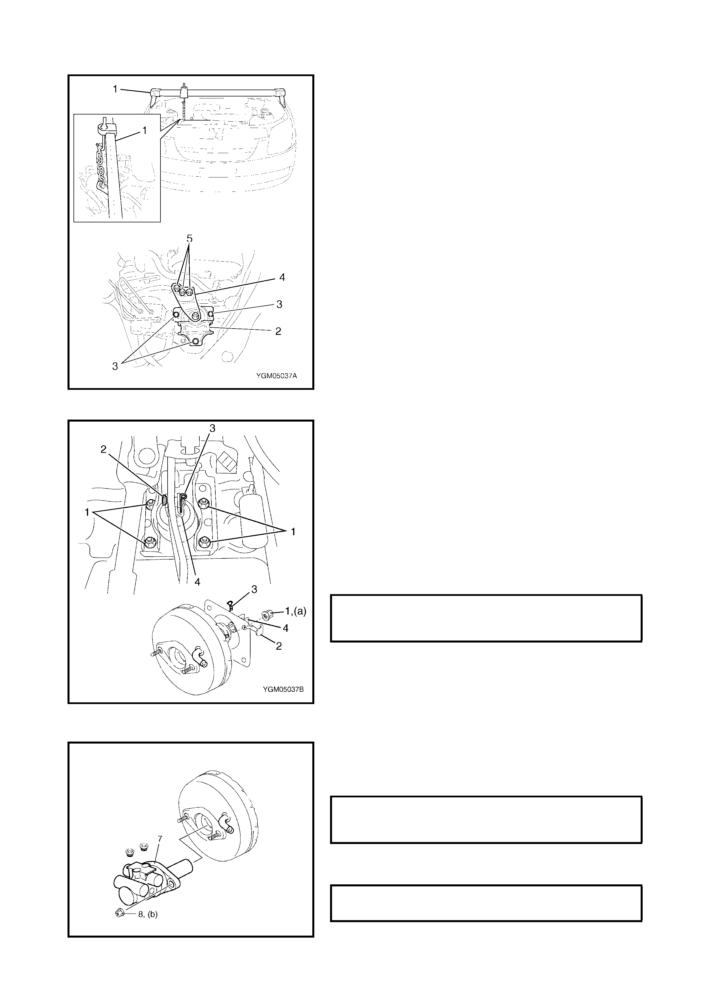
4. Support the right side of the engine using a support
device (1).
5. Remove the engine right side mount (2) and bracket
(4) by removing bolts (3) and bolts (5).
6. Lower the engine right side slightly to allow brake
booster re moval .
INSTALLATION
1. Check and adjust the clearance between the booster
piston rod and the master cylinder piston, refer to
3.5 BRAKE BOOSTER, INSPECTION AND
ADJUSTMENT in this Section.
2. Check and adjust the position of the push rod clevis,
refer to 3.5 BRAKE BOOSTER, INSPECTION AND
ADJUSTMENT in this Section.
3. Install the brake booster to the brake pedal and dash
panel. Tighten the booster mounting nuts (1) to the
specifi ed torque an d connec t the p ush rod clevi s (4) to
the pedal arm with clevis pin (2) and clip (3).
4. Tighten the engine right side mount and bracket bolts
and nuts to the specified torque. For tightening torque
refer to Section 6A1 ENGINE MECHANICAL, 3.8
ENGINE MOUNTINGS.
5. Remove support device.
6. Install new master cylinder gasket to booster.
7. Install master cylinder (7) to booster and tighten
mounting nuts (b) to specified torque.
8) Connect brake pipes and tighten flare nuts to spec-
ified to rq ue.
BRAKE BOOSTER MOUNTING
NUTS (a)
TORQUE SPECIFICAT ION 13 Nm
MASTER CYLINDER MOUNTING
NUTS (b)
TORQUE SPECIFICAT ION 13 Nm
BRAKE PIPE FLARE NUTS
TORQUE SPECIFICAT ION 16 Nm

9. Connect reservoir lead wire connector and booster
vacuum hose.
10. Fill brake reservoir with specified fluid.
11. Bleed air from the brake system, refer to
3.1 AIR BLEEDING OF BRAKE SYSTEM in this
Section.
12. After installing, check pedal height and play, refer to
2.5 BRAKE PEDAL FREE HEIGHT ADJUSTMENT
and 2.6 BRAKE PEDAL PLAY INSPECTION in this
Section.
13. Perform brake test and check each installed part for
fluid leakage.
INSPECTION AND ADJUSTMENT
Installation Position Of Push Rod Clevis
Inspect and adj us t the dis tance bet ween the boo ste r ins tal-
lation s urface (not in cluding packi ng) and the cen tre of the
clevis pi n (1) hole to standard va lue (a) and tighte n nut (2)
to specified torque.
Clearance Between Booster Piston Rod And Master
Cylinder Piston
The length of the booster piston rod (1) is adjusted to pro-
vide sp ec ified c le aranc e (a) bet ween the p is ton rod (1 ) end
and the master cylinder piston (2).
• Before measuring clearance, push booster piston rod
several times to ensure reaction disc is in place.
• Keep inside of booster at atmospheric pressure for
measurement.
Measur e length (a) of p iston r od , i. e. di s tance betwee n pi s-
ton rod and mating surface of booster-to-master cylinder.
NOTE: Remove gasket from booster, if equipped.
DISTANCE BETWEEN CENTRE OF
BOOSTER CLEVIS PIN HOLE AND
BOOSTER SURFACE (a)
STANDARD 97 -98 mm
CLEVIS PIN LOCK NUT (b)
TORQUE SPECIFICAT ION 19 Nm
LENGTH OF PISTON ROD (a) 30.3 - 30.5 mm
If the measurement is out of specification, adjust the
booster piston rod by turning the adjusting screw of the pis-
ton rod using special tool 09952-16020 (B).
3.6 BRAKE HOSE/PIPE
FRONT BRAKE HOSE/PIPE REMOVAL
1. Raise and support the vehicle correctly. Remove wheel.
NOTE: This operation is not necessary when removing pipes connected to the master cylinder.
2. Clean dirt and foreign material from both flexible hose ends and pipe end fittings.
3. Drain brake flu id in reser voi r.
CAUTION: Do not allow brake fluid to contact painted surfaces. If brake fluid is spilled on painted sur-
faces flush immediately with water.
4. Remove brake flexible hose or pipe, refer to the following figures.
INSTALLATION
Reverse brake flexible hose installation procedure, noting the following:
• Make s ur e th at t he s tee ring whe el is in a s tr aight-forwar d po si ti on a nd t hat the fle xible hose has no twists
or kinks.
• Check to make sure that the flexible hose does not contact any part of the suspension or with the steering
both in fu ll right lo ck and ful l left lock. If th ere is any contact, rem ove and cor rect. Fill an d maintain br ake
fluid level in reservoir.
• Bleed brake system. Refer to 3.1 AIR BLEEDING OF BRAKE SYSTEM in this Section.
• Perform brake test and check installed parts for fluid leaks.
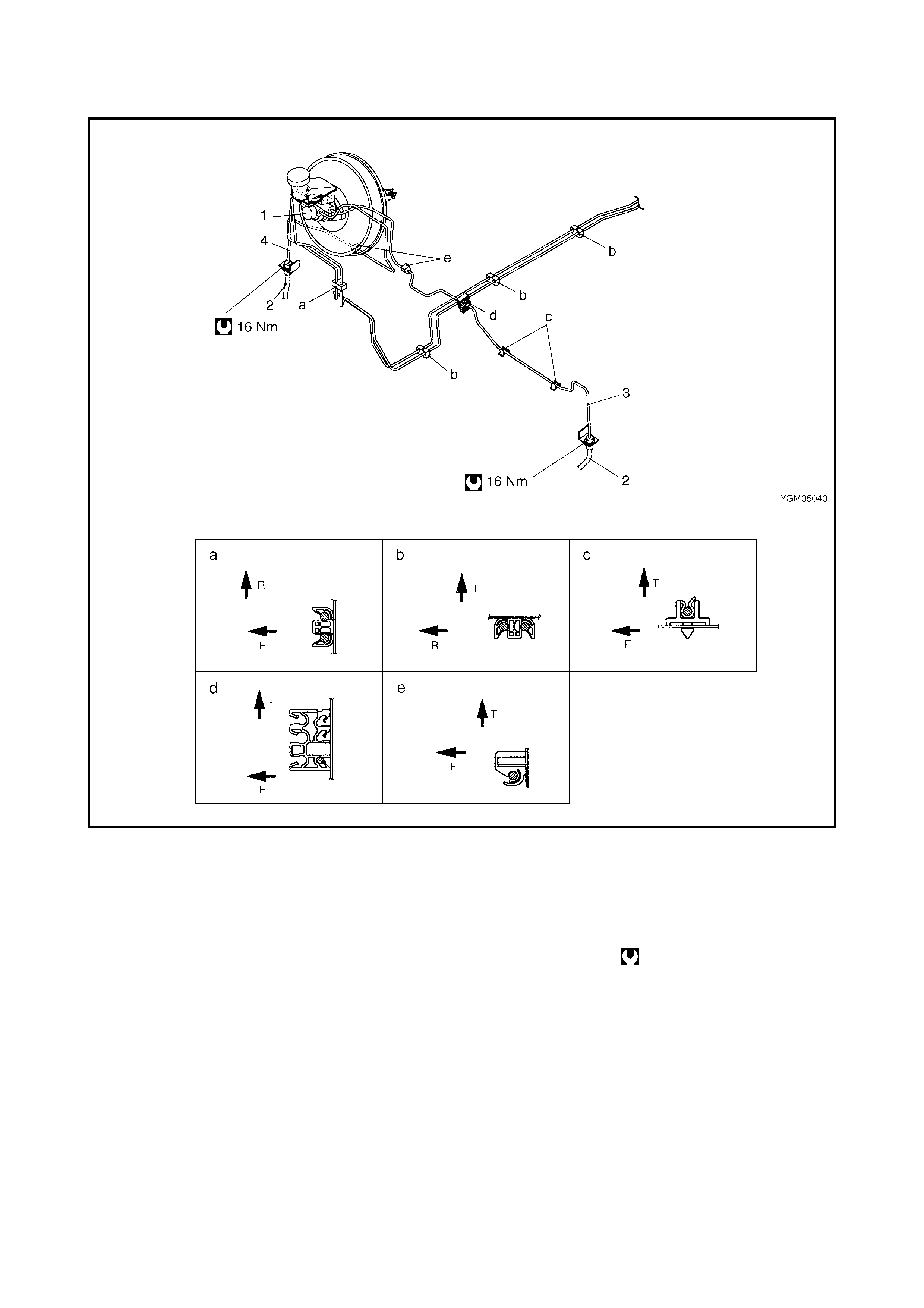
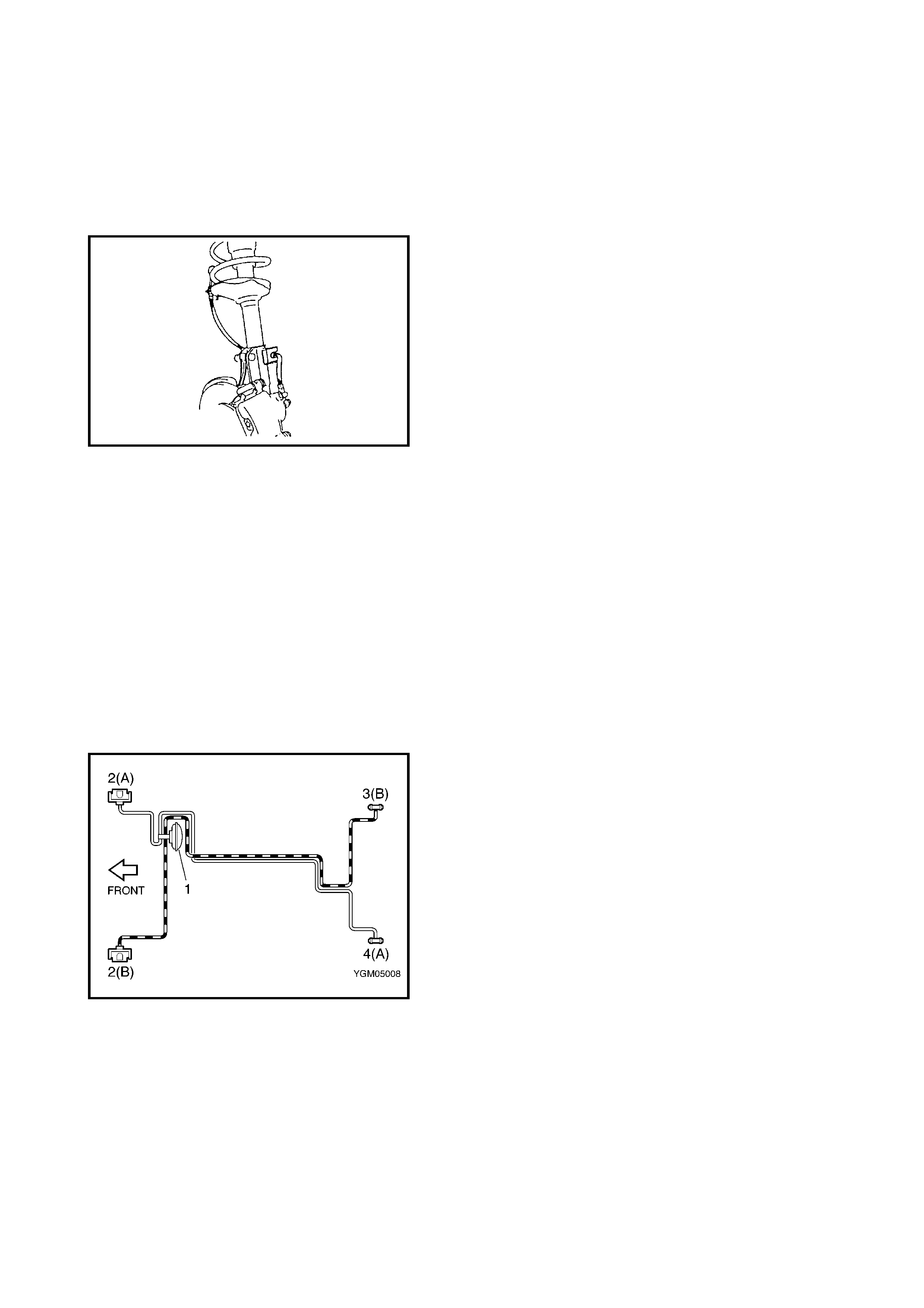
NON ABS VEHICLES
Legend
T: Top side c: View c 3. From master cylinder
primary to left front brake
F: Front si de d: View d
R: Right side e: View e 4. From master cylinder sec-
ondary to right front brake
a: View a 1. Master cylinder
b: View b 2. Front brake hose Tightening torque
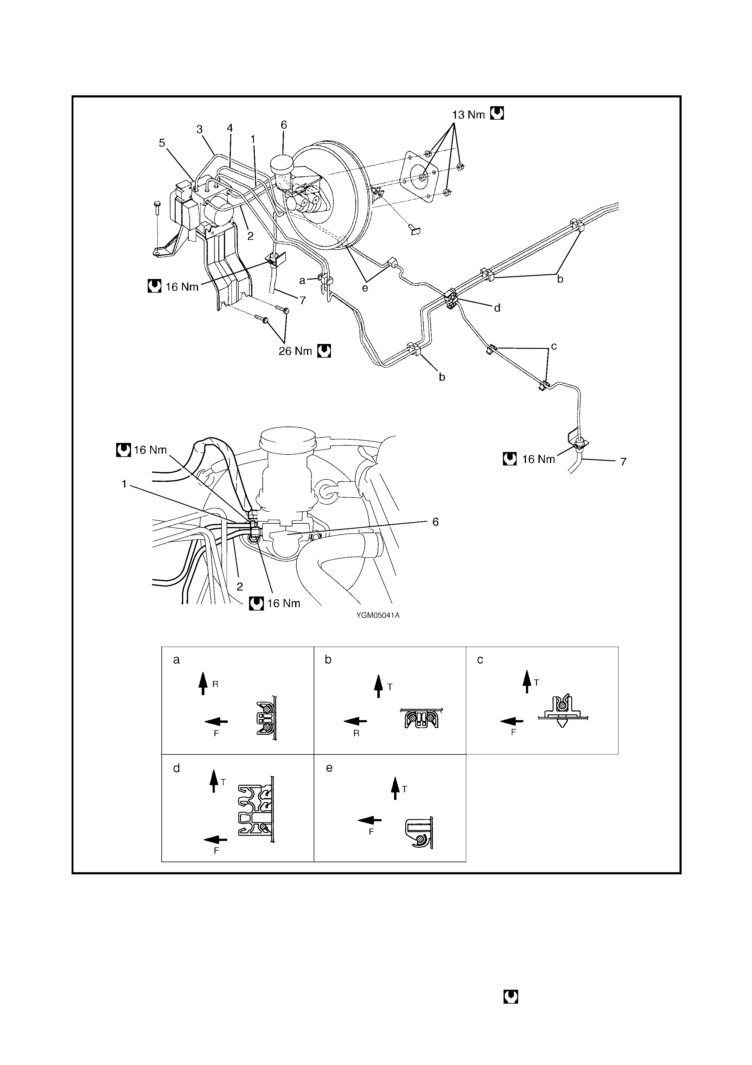
ABS VEHICLES
Legend
T: Top side e: View e 4. From ABS hydraulic unit to
right front brake
F: Fr ont side 1. From master cylind er prim ar y
to ABS hydraulic unit
R: Right side 5. ABS hydraulic unit
a: View a 2. From master cylinder
secondary to ABS hydraulic unit 6. Master cylinder
b: View b 7. Front brake hose
c: View c 3. From ABS hydraulic unit to left
front brake Tightening torque
d: View d

REAR BRAKE HOSE/PIPE REMOVAL
1. Raise and support the vehicle correctly. Remove wheel.
2. Clean dirt and foreign material from both flexible hose end and pipe end fittings.
3. Drain brake flu id in reser voi r.
CAUTION: Do not allow brake fluid to contact painted surfaces. If brake fluid is spilled on painted sur-
faces flush immediately with water.
4. Remove brake flexible hose or pipe, refer to the following figure.
REAR BRAKE HOSE/PIPE INSTALLATION
Reverse brake flexible hose installation procedure, nothing the following:
• Fill and maintain brake fluid level in reservoir.
• Bleed brake system. Refer to 3.1 AIR BLEEDING OF BRAKE SYSTEM in this Section.
• Perform brake test and check each installed part for fluid leakage.
• Install clamps properly referring to the figure and tighten bolts.
• When installing hose, make sure that it has no twists or kinks.
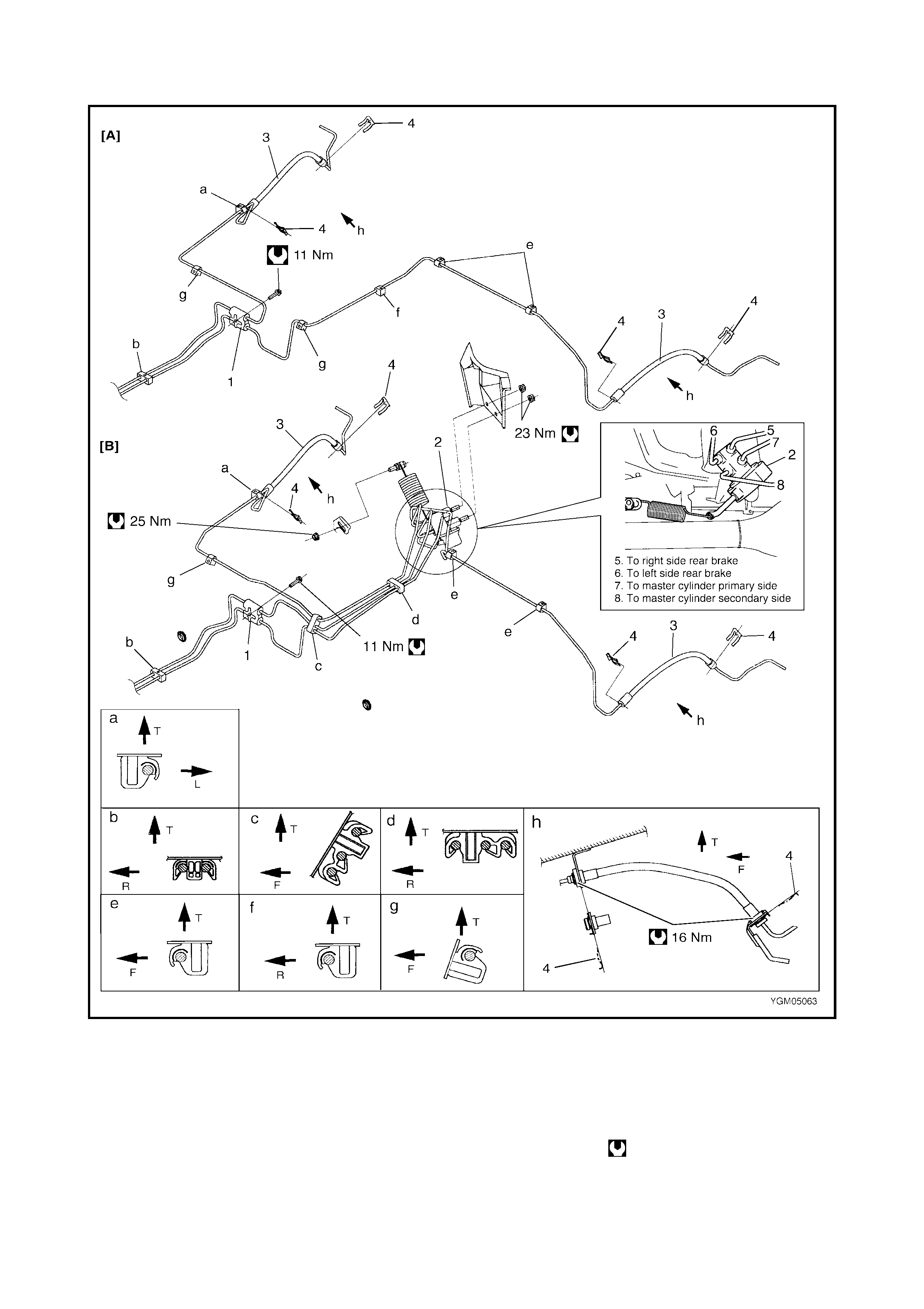
Legend
T : Top side d: View d 3. Rear brake hose
F : Front side e: View e 4. E-ring
R : Right side f: View f [A]: with ABS
L : Left side g: View g [B]: with LSPV
a: View a h: View h Tightening torque
b: View b 1. 4 way joint
c: View c 2. LSPV assembly
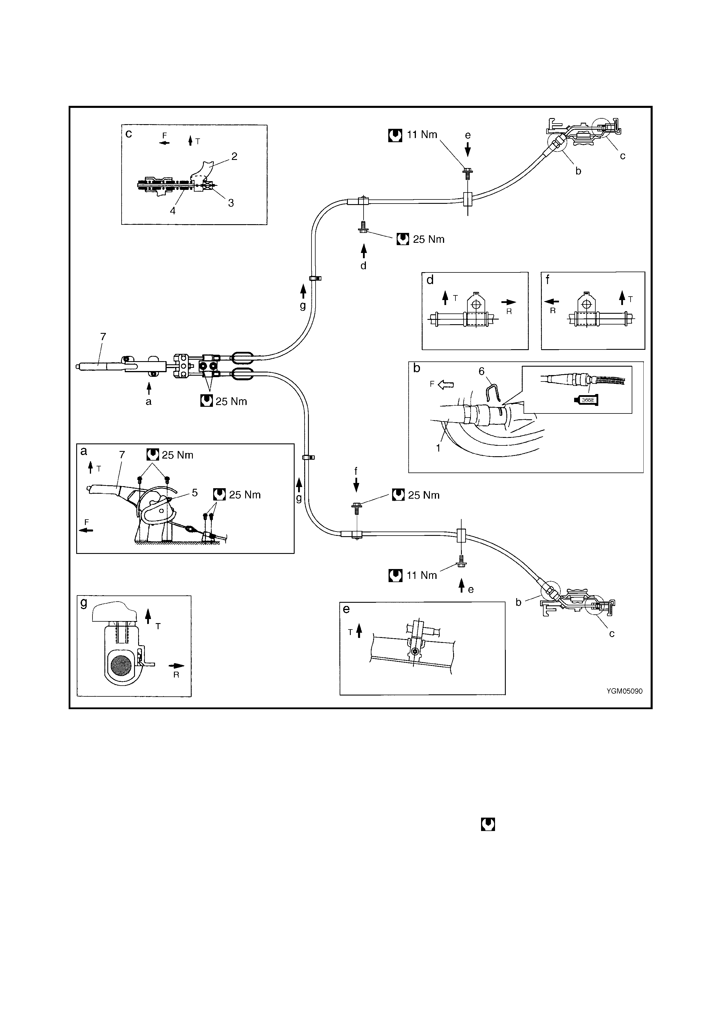
3.7 PARKING BRAKE CABLE
Legend
REMOVAL
1. Raise and support vehicle correctly. Remove wheel.
2. Disconnect parking brake cable from parking brake lever and clamps.
3. Disconnect parking brake cable from rear brake shoe lever, refer to 3.3 REAR BRAKE in this Section.
4. Remove parking brake cable.
T: Top side 3. Inner cable end c : View c
F: Front side 4. Spring d : View d
R: Rear side 5. Adjusting nut e : View e
1. Cable
:Apply water tight sealant
sealing compound 366E
6. Clip f : View f
7. Parking brake lever g: View g
a : View a Tightening torque
2. Parking brake shoe lever b : View b
INSTALLATION
Install it by reversing removal procedure, noting the following points.
• Install clamps properly referring to the figure.
• Tighten bolts and nuts to specified torque.
• Adjust parking brake cable (Refer to 2.10 PARKING BRAKE INSPECTION AND ADJUSTMENT in this
Section).
• Check brake drum for dragging and brake system for proper performance. After removing vehicle from
hoist, perform brake test.
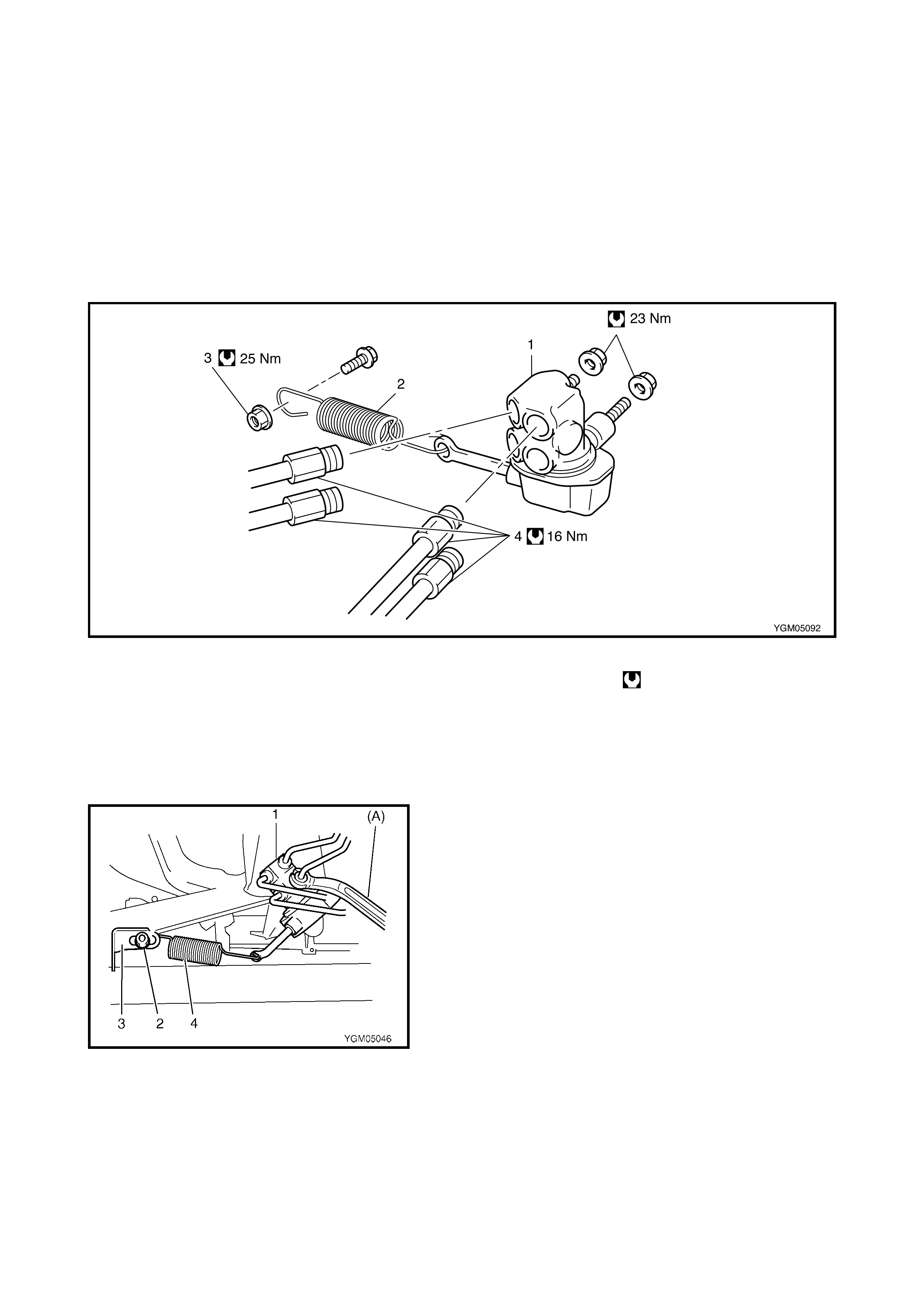
3.8 LSPV (LOAD SENSING PROPORTIONING VALVE) ASSEMBLY (IF EQUIPPED)
Legend
CAUTION: Never disassemble LSPV assembly. Disassembly will affect the original factory settings.
Replace whole unit with a new item if defective.
REMOVAL
1. Clean around reservoir cap and remove fluid with a
syringe or similar.
2. Hoist vehicle.
3. Disconnect brake pipes from LSPV assembly using
special tool 09950-78230 (A).
4. Remove nut (2) and detach spring end from rear axle
(3).
5. Remove LSPV assembly (1) with spring (4) from
vehicle body.
1. LS PV assembly 3. Adjust nut Tightening torque
2. Spring 4. Brake pipe
INSTALLATION
1. Install LSPV assembly with spring to vehicle body.
2. Torque each bolt and nut (1) to specification as
indicated respectively in figure using special tool
09950-782 30 (A) .
3. Fill reservoir with specified fluid and bleed air from
brake system.
4. After ble eding a ir, che ck that th e LSPV is ins talled co r-
rectly, refer to 3.8 LSPV ASSEMBLY, INSPECTION
AND ADJUSTMENT in this Sec tio n.
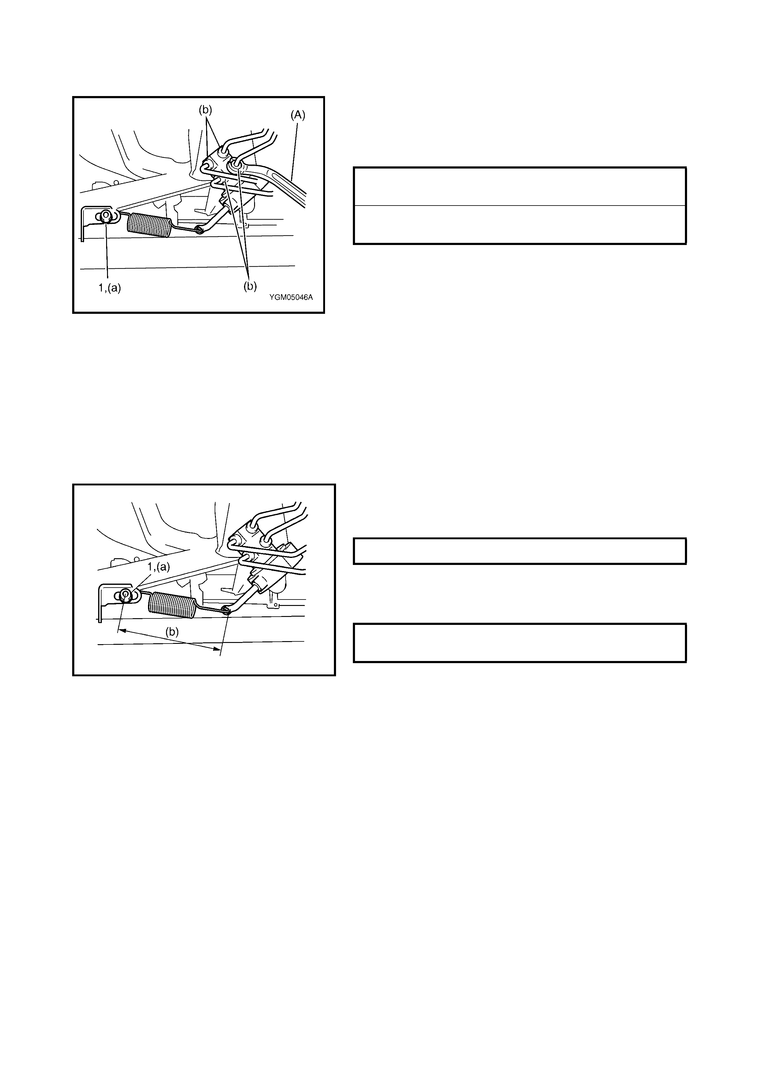
INSPECTION AND ADJUSTMENT
1. Confirm the following before inspection and adjust-
ment.
• Fuel tank is filled with fuel.
• Vehicle is equipped with spare tyre, tools, jack and jack
handle.
• Vehicle is free from any other load.
• Vehicle is placed on level floor.
2. Push up LSPV lever with finger until it stops and
measure length of coil spring (b) in figure.
3. Spring length (b) should be as specified.
4. If it isn’t, adjust it to specification by changing spring
position as shown in figure. After adjustment, tighten
nut (1) to specified torque.
NOTE: Check to make sure that LSPV body and brake
pipe joints are free from fluid leakage. Replace any defec-
tive parts.
5. Confirm fluid pressure refer to 2.11 FLUID PRESSURE
TEST in this Sectio n.
LSPV ADJUSTING NUT (a)
TORQUE SPECIFICAT ION 25 Nm
BRAKE PIPE FLARE NUTS (b)
TORQUE SPECIFICAT ION 16 Nm
SPRING LENGTH (b) 148 mm
LSPV ADJUSTING NUT (a)
TORQUE SPECIFICAT ION 25 Nm
4. REQUIRED SERVICE MATERIAL
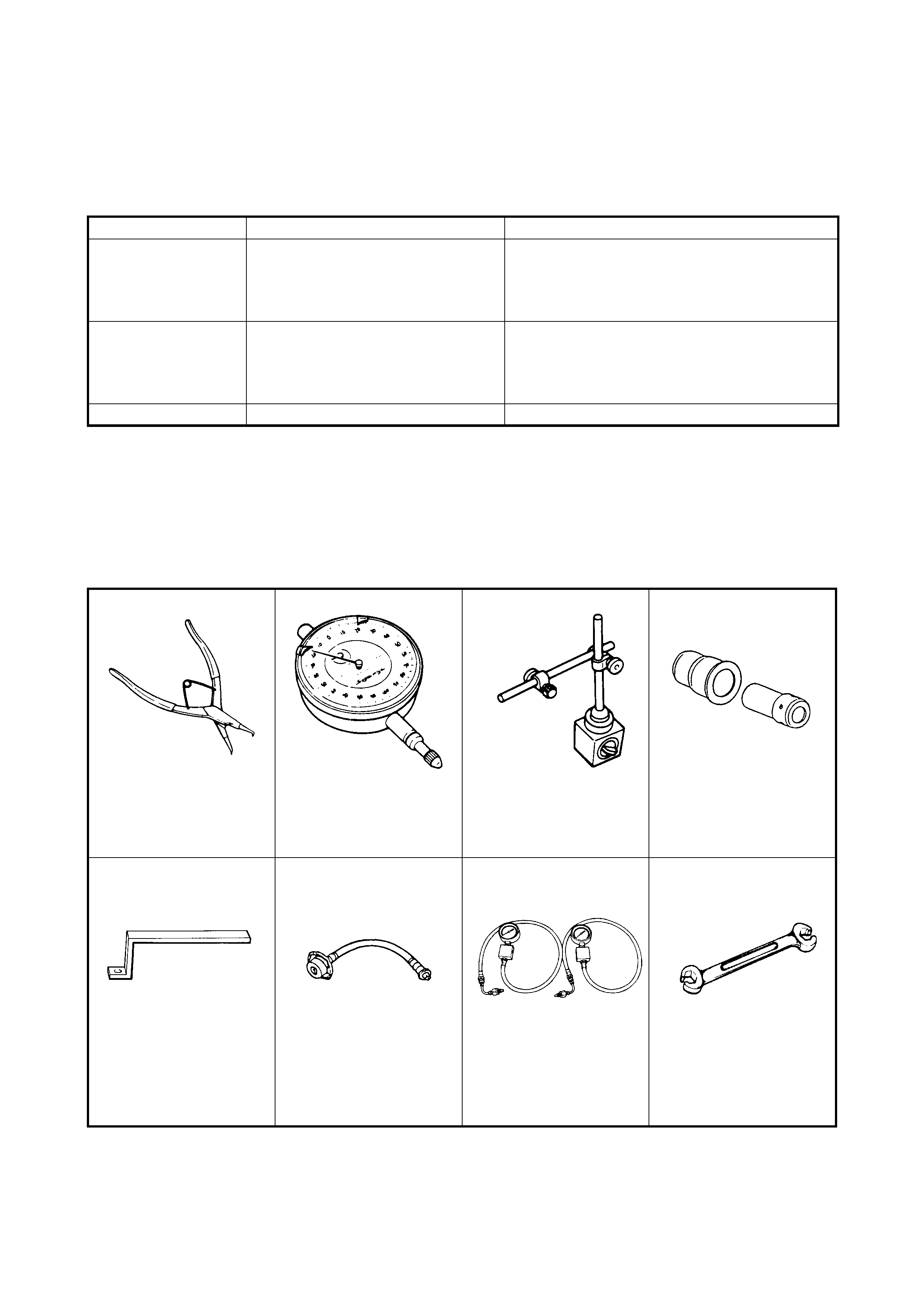
5. SPECIAL TOOLS
NOTE: Refer to Section 0A GENERAL INFORMATION – 7. CONSOLIDATED TOOLS for a detailed list of
special tools and the local eq uivalent if one is available
Material
Recommended product
Use
Brake fluid DOT 3 or SAE J1703 To fill master cylinder reservoir.
To clean and apply to inner part s of master cyl-
inder caliper and wheel cylinder when they are
disassembled.
W ater tight sealant Sealing Compound 366E To apply to mating surfaces of brake back plate
and rear axle hous i ng.
To apply to mating surfaces of brake back plate
and parking brake cable.
Lithium grease Lithium Grease To apply to slide pin of brake caliper carrier.
09900-06106 09900-20606 09900-20701 09951-18220
Snap ring remover Dial gauge Dial gauge chuck Secondary cup installer
set
09952-16020 09952-46010 09956-02310 09950-78230
Booste r pisto n rod
adjuster Master cylinder attach-
ment Fluid pressure gauge Flare nut wrench
(10 x 11 mm)
09952-36311 09952-26020
Pressure gauge attach-
ment Master cylinder plug