
SECTION 5E - ANTIL OCK BRAKE SYSTEM (ABS)
WARNING:
For vehicles equipped with Supplementary Restraint (Airbag) System:
• Service on and around the airbag system components or wiring must be performed only by an
authorised HOLDEN retailer. Refer to AIRBAG SYSTEM COMPONENTS and WIRING LOCATION
VIEW under GENERAL DESCRIPTION in Section 10B AIRBAG SYSTEM in order to confirm
whether you are performing service on or near the airbag system components or wiring. Please
observe all WARNINGS and SERVICE PRECAUTIONS under ON-VEHICLE SERVICE in Section
10B AIRBAG SYSTEM before per forming service on or around the airba g system components or
wiring. Failure to follow WARNINGS could result in unintentional activation of the system or
could render the system inoperative. Either of these two conditions may result in severe injury.
•
Technical service work must be started at least 90 seconds after the ignition switch is turned to
the LOCK position and the negative cable is disconnected from the battery. Otherwise, the sys-
tem may be activated by reserve energy in the Sensing and Diagnostic Module (SDM)
.
NOTE:
All brake fasteners are important attaching parts in that they could affect the performance of
vital parts and systems, and/or could result in major repair expense. They must be replaced
with one of sa me par t nu mbe r or wit h an eq ui va lent part if rep lace men t becom es n ec ess ary. Do
not use a replacement part of lesser quality or substitute design. Torque values must be used
as specified during reassembly to assure proper retention of all parts. There is to be no weld-
ing as it may result in extensive damage and weakening of the metal.
IMPORTANT:
Prior to connecting Tech 2 to the vehicle, refer to Section 0C TECH 2.
1. GENERAL DESCRIPTION
1.1 COMPONENTS / PARTS LOCATION
AND BRAKE HOSE/PIPE ROUTING
1.2 SYSTEM SCHEMATIC
1.3 ABS HYDRAULIC UNIT / CONTROL
MODULE ASSEMBLY
Self-Diagnosis Function
Fail-Safe Function
1.4 SYSTEM CIRCUIT
2. DIAGNOSIS
2.1 PRECAUTIONS IN DIAGNOSING
TROUBLES
2.2 ABS DIAGNOSTIC FLOW TABLE
2.3 ABS WARNING LAMP CHECK
2.4 EBD (BRAKE) WARNING LAMP CHECK
2.5 TABLE – A ABS WARNING LAMP
CIRCUIT CHECK Lamp Does Not Come
ON at Ignition Switch ON
Circuit Description
Inspection
2.6 TABLE – B ABS WARNING LAMP
CIRCUIT CHECK Lamp Comes ON
Steady
Inspection
2.7 TABLE – C ABS WARNING LAMP
CIRCUIT CHECK The Lamp Flashes
Continuously While Ignition Switch is
ONCircuit Description
Inspection
2.8 TABLE – D CODE (DTC) IS NOT OUTPUT
EVEN WITH DIAGNOSIS SWITCH
TERMINAL CONNECTED TO GROUND
Circuit Description
Inspection
2.9 TABLE – E EBD (BRAKE) WARNING
LAMP CHECK Lamp Comes ON Steady
Circuit Description
Inspection
2.10 DIAGNOSTIC TROUBLE CODE (DTC)
CHECK (USING ABS WARNING LAMP)
Techline
Techline

2.11 DIAGNOSTIC TROUBLE CODE (DTC)
CHECK (USING Tech 2)
2.12 DIAGNOSTIC TROUBLE CODE (DTC)
CLEARANCE
2.13 DIAGNOSTIC TROUBLE CODE (DTC)
TABLE
2.14 DTC C1015 (DTC 15) – G-SENSOR
CIRCUIT
Description
Inspection
2.15 DTC C1021 (DTC 21), DTC C1022 (DTC
22) RIGHT-FRONT WHEEL SPEED
SENSOR CIRCUIT OR SENSOR RING
DTC C1025 (DTC 25), DTC C1026 (DTC
26) LEFT-FRONT WHEEL SPEED
SENSOR CIRCUIT OR SENSOR RING
DTC C1031 (DTC 31), DTC C1032 (DTC
32) RIGHT-REAR WHEEL SPEED
SENSOR CIRCUIT OR SENSOR RING
DTC C1035 (DTC 35), DTC C1036(DTC
36) LEFT-REAR WHEEL SPEED
SENSOR CIRCUIT OR SENSOR
RING
Description
Inspection
2.16 DTC C1041 (DTC 41) – RIGHT-FRONT
INLET SOLENOID CIRCUIT DTC C1045
(DTC 45) – LEFT-FRONTINLET
SOLENOID CIRCUITDTC C1051 (DTC
51) – RIGHT-REARINLET SOLENOID
CIRCUIT DTC C1055 (DTC 55) –
LEFT-REAR INLET SOLENOID
CIRCUITDTC C1042 (DTC 42) –
RIGHT-FRONTOUTLET SOLENOID
CIRCUIT DTC C1046 (DTC 46) –
LEFT-FRONTOUTLET SOLENOID
CIRCUIT DTC C1052 (DTC 52) –
RIGHT-REAROUTLET SOLENOID
CIRCUIT DTC C1056 (DTC 56) –
LEFT-REAR OUTLET SOLENOID
CIRCUIT
Description
Inspection
2.17 DTC C1057 (DTC 57) – POWER SOURCE
CIRCUIT
Description
Inspection
2.18 DTC C1061 (DTC 61) – ABS PUMP
MOTOR CIRCUIT
Description
Inspection
2.19 DTC C1063 (DTC 63) – ABS FAIL-SAFE
RELAY CIRCUIT
Description
Inspection
2.20 DTC C1071 (DTC 71) – ABS CONTROL
MODULE
Description
Inspection
3. ON-VEHICLE SERVICE
3.1 PRECAUTIONS
3.2 ABS HYDRAULIC UNIT OPERATION
CHECK (USING TECH 2)
3.3 ABS HYDRAULIC UNIT OPERATION
CHECK (NOT USING TECH 2)
3.4 ABS HYDRAULIC UNIT/CONTROL
MODULE ASSEMBLY
Hydraulic Unit Inspection
Removal
Installation
3.5 FRONT WHEEL SPEED SENSOR
Output Voltage Inspection
Reference
Removal
Sensor Inspection
Sensor Ring Inspection
Installation
3.6 FRONT WHEEL SPEED SENSOR RING
3.7 REAR WHEEL SPEED SENSOR
Output Voltage Inspection
Reference
Removal
Sensor Inspection
Sensor Ring Inspection
Installation
3.8 REAR WHEEL SPEED SENSOR RING
Removal / Installation
3.9 G-SENSOR
Removal
Inspection
Installation
4. SPECIAL TOOLS
1. GENERAL DESCRIPTION
The ABS (Antilock Brake System) controls the fluid pressure applied to the wheel cylinder of each brake from
the master cylinder so that each wheel is not locked even when hard braking is applied.
This ABS also has the following function.
While braking is applied, b ut before ABS control bec omes effective, braking for ce is distrib uted between th e
front and rear so as to prevent the rear wheels from being locked too early for better stability of the vehicle.
The main component parts of this ABS include the following parts in addition to those of the conventional
brake system.
• Wheel speed sensor which senses revolution speed of each wheel and outputs its signal.
• ABS warning lamp which lights to inform a fault when system fails to operate properly.
• ABS hydraulic unit/control module assembly is incorporated ABS control module, ABS hydraulic unit
(actuator assembly), fail-safe relay and pump motor relay.
•ABS co ntrol mod ule which s ends oper ation signal to ABS hydr aulic u nit to contr ol fluid pres sure app lied
to each wheel cylinder based on signal from each wheel speed sensor so as to prevent wheel from
locking.
•ABS hy draulic unit wh ich op erates ac cord ing to sig nal fro m ABS con trol m odule to contr ol fluid pr essu re
applied to wheel cylinder of each 4 wheels.
•Fail-safe relay (solenoid valve relay) which supplies power to solenoid valve in ABS hydraulic unit and
pump motor relay.
•Pump motor relay which supplies power to pump motor in ABS hydraulic unit.
• G-sensor which detects body deceleration speed.
This ABS is equipped with Electronic Brake force Distribution (EBD) system that controls fluid pressure to the
rear wheels to the best condition, which is the same function as that of a proportioning valve, by the signal
from w heel sensor independe ntly of change of load due to load capacity and so on. And if the EBD system
fails to operate properly, the brake warning lamp lights to inform of a fault.
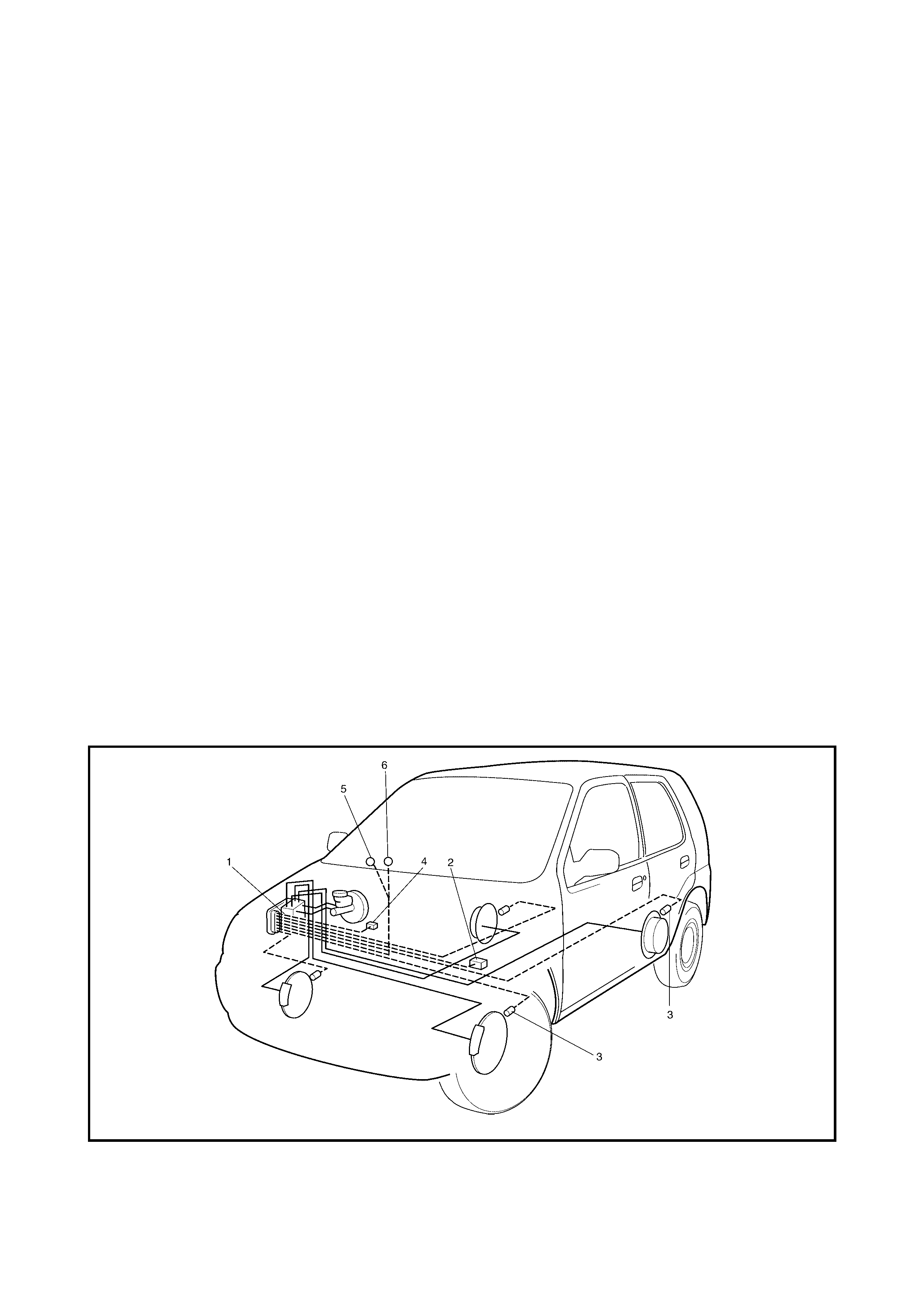
1.1 COMPONENTS / PARTS LOCATION AND BRA KE HOS E/PIPE ROUTING
Legend
1. ABS hydraulic unit/control module assembly 4. S top lamp switch
2. G-sens or 5. ABS war ni ng lamp
3. Wheel speed sensors 6. EBD warning lamp (Brake warning lamp)
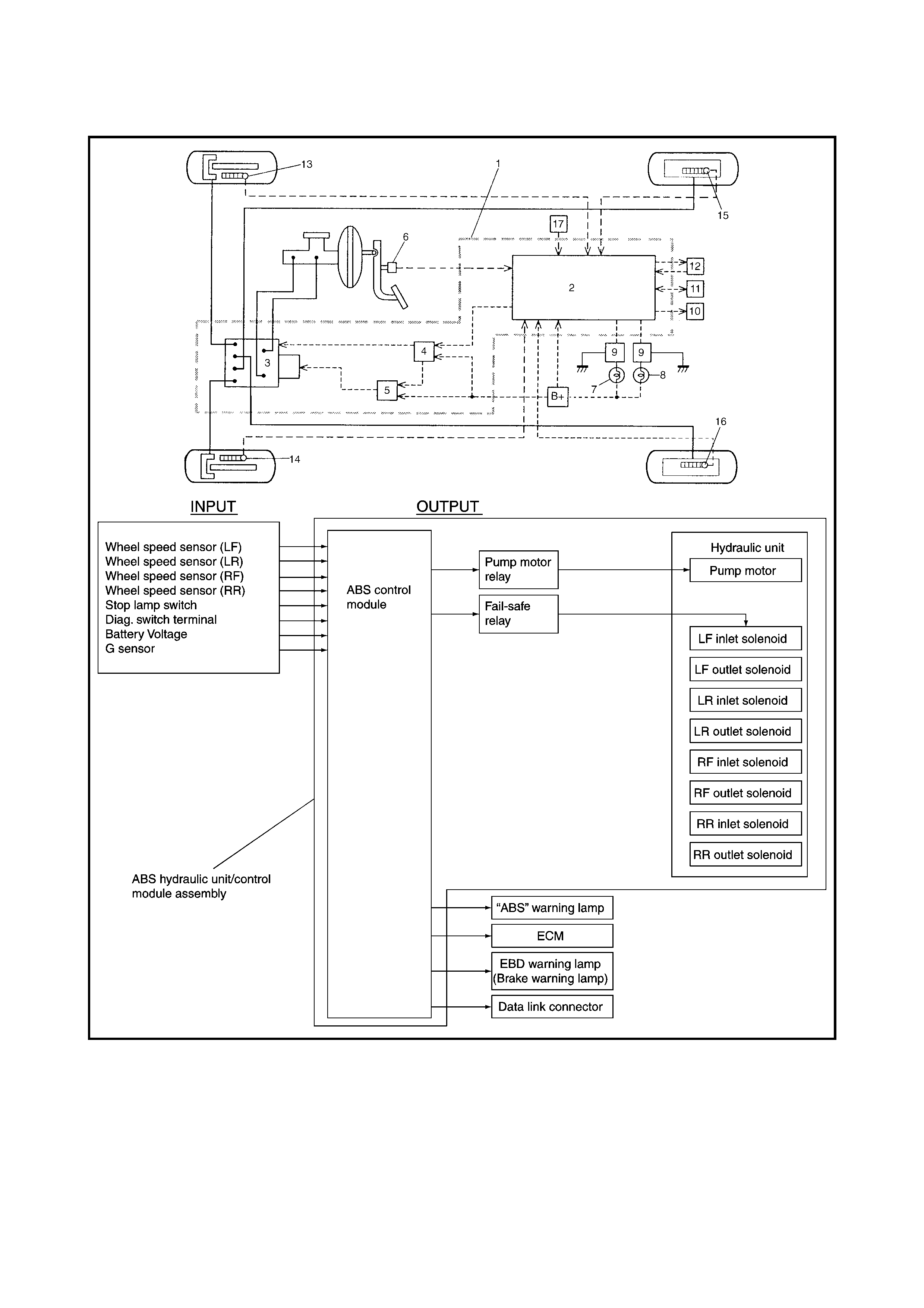
1.2 SYSTEM SCHEMATIC
Legend
1. ABS hydraulic unit/control module assembly 10. ECM
2. ABS control module 11. Data link connector
3. ABS hydraulic unit 12. Diagnosis connector No.2
4. Fail safe relay 13. Wheel speed sensor (Right-front)
5. Pump motor relay 14. Wheel speed sensor (Left-front)
6. Stop lamp switc h 15. Wheel speed se ns or (Righ t- rear )
7. ABS warning lamp 16. Wheel speed sensor (Left-rear)
8. EBD warning lamp (Brake warning lamp) 17. G-sensor
9. Lamp driver module
1.3 ABS HYDRAULIC UNIT / CONTROL MODULE ASSEMBLY
The ABS control module is a component of ABS hydraulic
unit/control module assembly and has the following func-
tions.
SELF-DIAGNOSIS FUNCTION
The ABS control module diagnoses conditions of the sys-
tem com ponent parts (whether or not there is any fault) all
the time and indicates the results (warning of fault occur-
rence and DTC) through the ABS warning lamp as
described below.
1. When the ignition switch is turned ON, the ABS
warning lam p li ghts for 2 seconds to ch eck its bulb and
circuit.
2. When no fault has been detected (the system is in
good condition), the ABS warning lamp turns OFF after
2 seconds.
3. When an fault in the system is detected, the ABS
warning lamp lights and the area where that fault lies is
stored in the memory of EEPROM in ABS control
module.
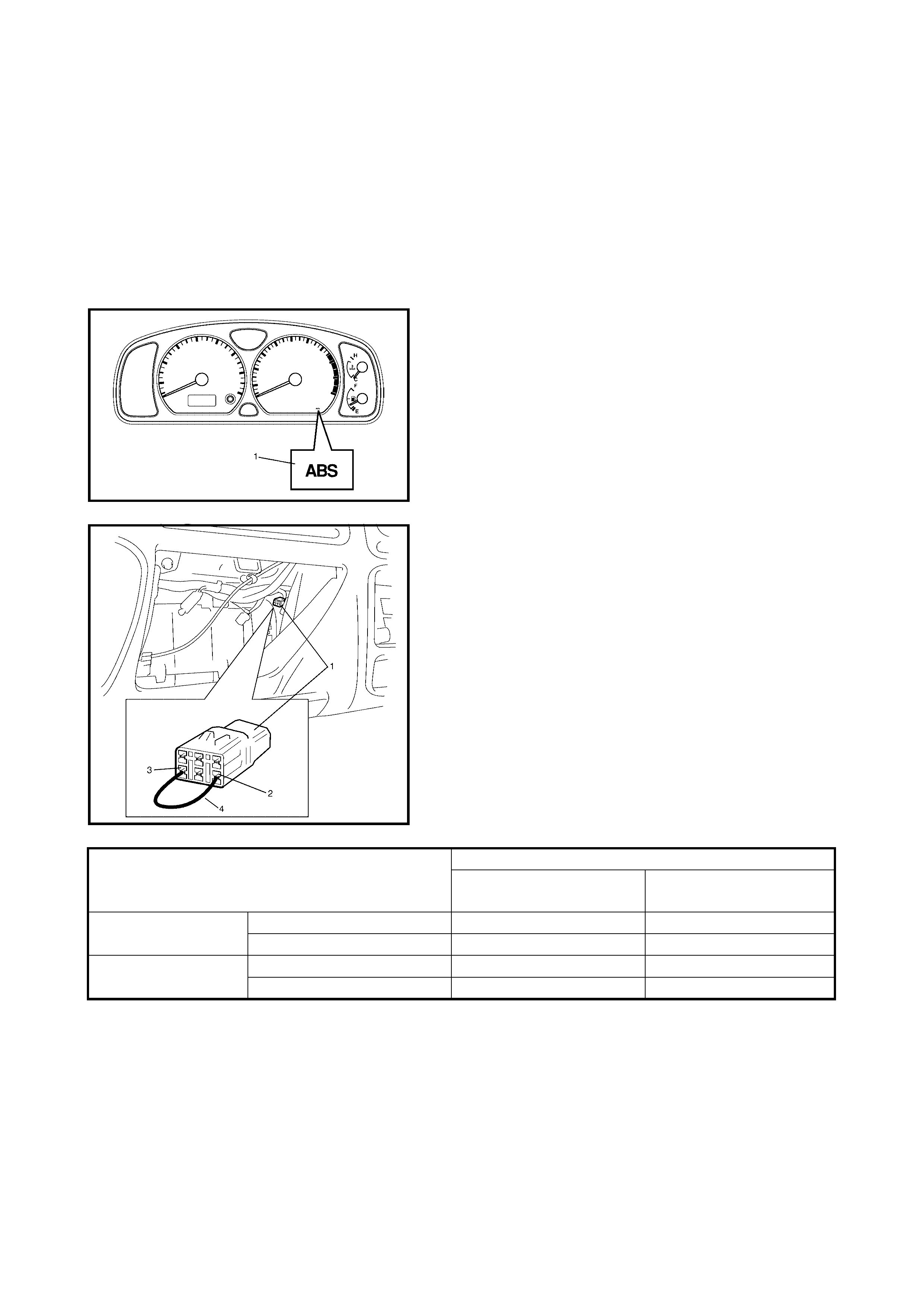
4. When the Diagnostic switch terminal (2) of diagnosis
connector No.2 (1) is grounded (3) with service wire
(4), the fault is output as DTC. It is indicated by flashing
of ABS warning lamp. (Refer to the table below.)
5. For the procedures to clear DTC’s, refer to
2.12 DIAGNOSTIC TROUBLE CODE CLEARANCE in
this Section.
Also, the ABS control module turns ON the EBD (brake)
warning lamp, depending on the fault that has been
detected by the module. The EBD warning lamp does not
indicate DTCs as well as the ABS warning lamp.
FAIL-SAFE FUNCTION
When a fault occurs (a fault DTC is detected), the ABS
contro l mo dul e tu rns O F F the fai l-sa fe r ela y whi ch su ppl ies
power to ABS hydraulic unit. Thus, with ABS not operating,
the brake system functions as a vehicle without ABS.
SYSTEM CONDITION ABS WARNING LAMP
Diag. switch terminal is not
grounded Diag. switch terminal is
grounded
In good condition at
present No fault in the past OFF DTC 12
Fault occurred in the past OFF History DTC
Fault exists at present No fault in the past ON Current DTC
Fault occurred in the past ON Current and history DTCs
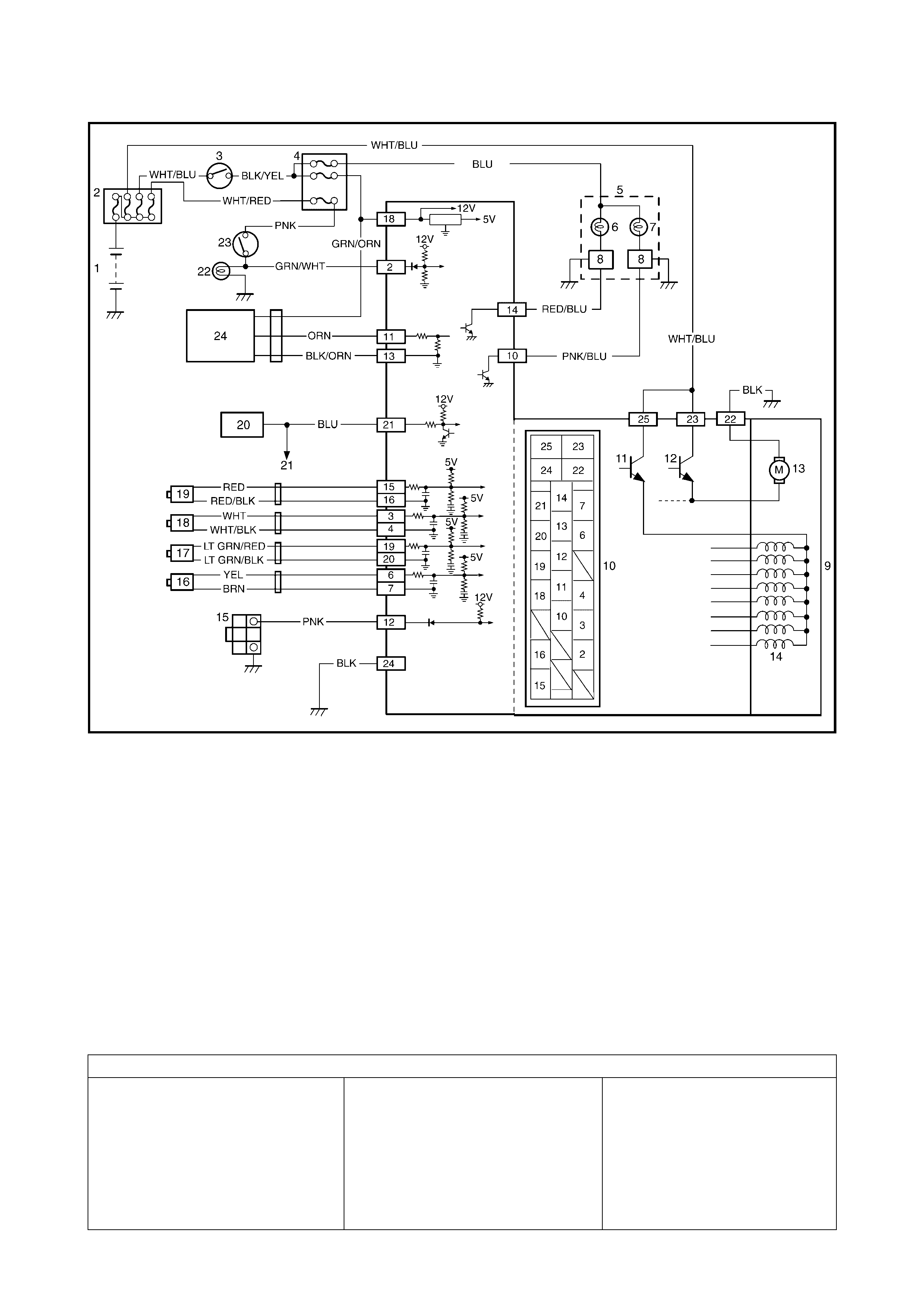
1.4 SYST EM CIRCUIT
Legend
1. Battery 13. Pump motor
2. Main fuses 14. Solenoid valves
3. Ignition switch 15. Diagnosis connector No. 2
4. Circuit fuses 16. Right-rear wheel speed sensor
5. Combination meter 17. Left-rear wheel speed sensor
6. ABS warning lamp 18. Right-front wheel speed sensor
7. Brake warning lamp (EBD warning lamp) 19. Left-front wheel speed sensor
8. Warning lamp driver module (for ABS) 20. Data link connector
9. ABS hydraulic unit/control module assembly 21. To ECM, SDM and EPS controller (if equipped)
10. Terminal arrangement of connector E19 22. Stop lamp
11. ABS fail-safe relay (Solenoid valve relay) 23. S top lamp switch
12. ABS pump motor relay 24. G-sensor
Wire col our
BLK: Black LT GRN/BLK: Light Green/Black RED/BLU: Red/Blue
BLK/ORN: Black/Orange LT GRN/RED: Light Green/Red WHT: White
BLK/YEL: Black/Yellow ORN: Orange WHT/BLK: White/Black
BLU: Blue PNK: Pink WHT/BLU: White/Blue
BRN: Brown PNK/BLU Pink/Blue WHT/RED: White/Red
GRN/WHT: Green/White RED: Red YEL: Yellow
GRN/ORN: Green/Orange RED/BLK: Red/Black

2. DIAGNOSIS
To ensure that the fault diagnosis is done accurately and smoothly, observe PRECAUTIONS IN
DIAGNOSING TROUBLES and follow ABS DIAGNOSTIC FLOW TABLE.
2.1 PRECAUTIONS IN DIAGNOSING TROUBLES
• If the vehicle was operated in any of the following
ways, the ABS warning lamp may light momentarily.
This does not indicate anything abnormal in the ABS.
•The vehicle was driven with parking brake on.
•The vehicle was driven with brake dragging.
•The vehicle was stuck in mud, sand, etc.
•Wheel spin occurred while driving.
•Wheel was rotated while the vehicle was jacked up.
• Refer to Section 0A, 1.6 PRECAUTIONS FOR
ELECTRONIC CIRCUIT SERVICE before inspection
and observe what is written there.
• Use the fault diagnosis procedure as described in the
flow table. Failure to f ollow the flow table may result i n
incorrect diagnosis. (Some other diagnosis trouble
code may be s tored by mistake in the me mory of ABS
control module during inspection.)
TERMINAL CIRCUIT
E19 1 –
2 Stop lamp switch
3 Rig ht-f ront wheel spe ed se nso r (+)
4 Rig ht-f ront wheel spe ed se nso r (–)
5–
6 Right-rear wheel speed sensor (–)
7 Right-rear wheel speed sensor (+)
8–
9–
10 Brake warning lamp (EBD warning lamp)
11 G-sensor
12 Diagnosis switch terminal
13 Ground (For G-sensor)
14 ABS warning lamp
15 Left-front wheel speed sensor (+)
16 Left-front wheel speed sensor (–)
17 –
18 Ignition switc h
19 Left-rear wheel speed sensor (+)
20 Left-rear wheel speed sensor (–)
21 Data link connector
22 Ground (for ABS pump motor)
23 Power supply for ABS pump motor
24 Ground (for ABS control module)
25 Power supply for solenoid valves

• When disconnecting the ABS hydraulic unit/control
module connector (1), pull up lock (2) of connector.
When connecting, set the connector on the ABS
hydraulic unit/control module assembly and push the
lock (2) down.
2.2 ABS DIAGNOSTIC FLOW TA BLE
Refer to the following pages for the details of each step.
1. MALFUNCTION ANALYSIS
•Customer Complaint Analysis
Record details of the problem (failure, complaint) and how it occurred as described by the customer.
For this purpose, use of such a questionnaire form as shown below will facilitate collecting information
to the point required for proper analysis and diagnosis.
Step Action Yes No
1 1. Perform Customer Complaint Analysis.
2. Perform Problem Symptom Confirmation.
3. Perform Diagnostic T rouble Code Check, Record and
Clearance.
Is there any malfu nctio n DTC?
Go to Step 2. Go to Step 5.
2 Perform DRIVING TEST.
Is trouble symptom identified? Go to Step 3. Go to Step 6.
3 Check diagnostic trouble code.
Is it malfunction code? Go to Step 4. Go to Step 5.
4 1. Inspect and repair referring to applicable diagnostic
trouble code table in this Section.
2. Perform FINAL CONFIRMATION TEST after cleared
DTC.
Does trouble recur?
Go to Step 7. End.
5 1. Inspect and repair referring to DIAGNOSIS in Section
5, BRAKES.
2. Perform FINAL CONFIRMATION TEST.
––
6 1. Check intermittent troubles referring to INTERMIT-
TENT AND POOR CONNECTION in GENERAL
INFORMATION Section and related circuit of trouble
code r ecorded in Step 2.
2. Perform FINAL CONFIRMATION TEST after cleared
diagnostic trouble code.
Does trouble recur?
Go to Step 7. End.
7 Perform Diagnostic Trouble Code Check, Record and
Clearance.
Is there any malfu nc tio n code?
Go to Step 2. Go to Step 5.
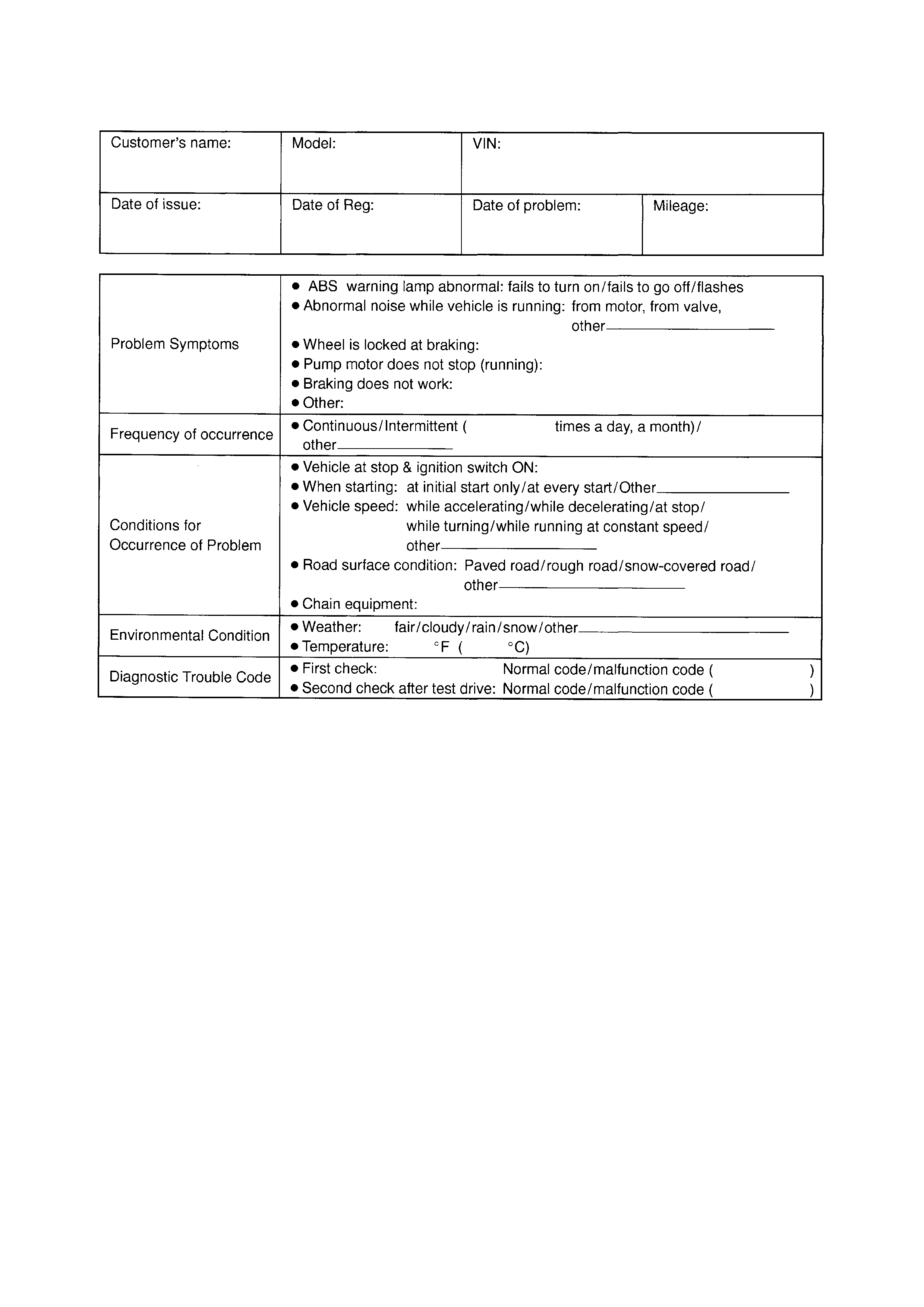
Customer Questionnaire (Exampl e)
•Problem Sy mpt om Confi r mation
Check if what the customer claimed in CUSTOMER QUESTIONNAIRE is actually found in the vehicle
and if that symptom is found, whe ther it is id entifi ed as a fail ure. (Thi s step shou ld be shared with the
customer if possible.) Check warning lamps related to the brak e syste m, refer to
2.4 EBD (BRAKE) WARNING LAMP CHECK and 2.3 ABS WARNING LAMP CHECK in this Sectio n.
•Diagnostic Trouble Code (DTC) Check, Record and Clearance
Perform a DIAGNOSTIC TROUBLE CODE CHECK procedure, refer to 2.10 DIAGNOSTIC TROUBLE
CODE (DTC) CHECK (USING ABS WARNING LAMP) and 2.11 DIAGNOSTIC TROUBLE CODE
(DTC) CHECK (USING Tech 2) in this Section, record it and then clear it referring to
2.12 DIAGNOSTIC TROUBLE CODE CLEARANCE in this Section.
If the malfunction DTC which was once displayed and then cleared cannot be detected (indicated)
again when the ignition switch is turned ON, attempt to diagnose the trouble based on the DTC
recorded in this step may mislead the diagnosis or make diagnosing difficult. Proceed to Step 2. to
check control module for proper self-diagnosis function.
If the ma lfunction DT C which wa s onc e dis play ed an d th en c lea red c an be de tec ted (in dic at ed) a gai n
when ignition switch is turned ON, proceed to Step 3).
2. DRIVING TEST
Test drive the vehicle at 40 km/h for more than a minute and check if any trouble symptom (such as
abnormal lighting of ABS warning light) exists.
If the malfun ction DTC is confirme d again at ign ition swit ch ON, the driv ing test as des cribed in a bove is
not necessary. Proceed to Step 3).
3. DIAGNOSTIC TROUBLE CODE CHECK
Recheck diagnostic trouble code referring to DTC CHECK as shown in the following page.
4. DIAGNOSTIC TROUBLE CODE FLOW TABLE
According to the Diagnostic flow table for the diagnostic trouble code confirmation in Ste p 3., locate the
cause of the trouble, namely in a sensor, switch, wire harness, connector, actuator assembly or other part
and repair or replace faulty parts.
5. DIAGNOSIS IN BRAKES SECTION
Check the parts or system suspect ed as a possible c ause, refer t o Section 5, 2. DIA GNOSIS and b ased
on symptoms appearing on the vehicle (symptom obtained through Steps 1-a, 1-b and 2. and repair or
replace faulty parts, if any.
6. CHECK FOR INTERMITTENT PROBLEM
Check parts where an intermittent trouble is easy to occur (e.g., wire harness, connector, etc.), refer to
INTERMITTENTS AND POOR CONNECTIONS in Section 0A, 1.7 ELECTRICAL CIRCUIT INSPECTION
PROCEDURE and related circuit of trouble code recorded in Step 1-c.
7. FINAL CONFIRMATION TEST
Confirm that the pro blem symptom h as gone and the ABS is f ree from an y abnormal c onditions. If wh at
has been repaired is related to the malfunction DTC, clear the DTC once and perform test driving and
confirm that no DTC is indicated.
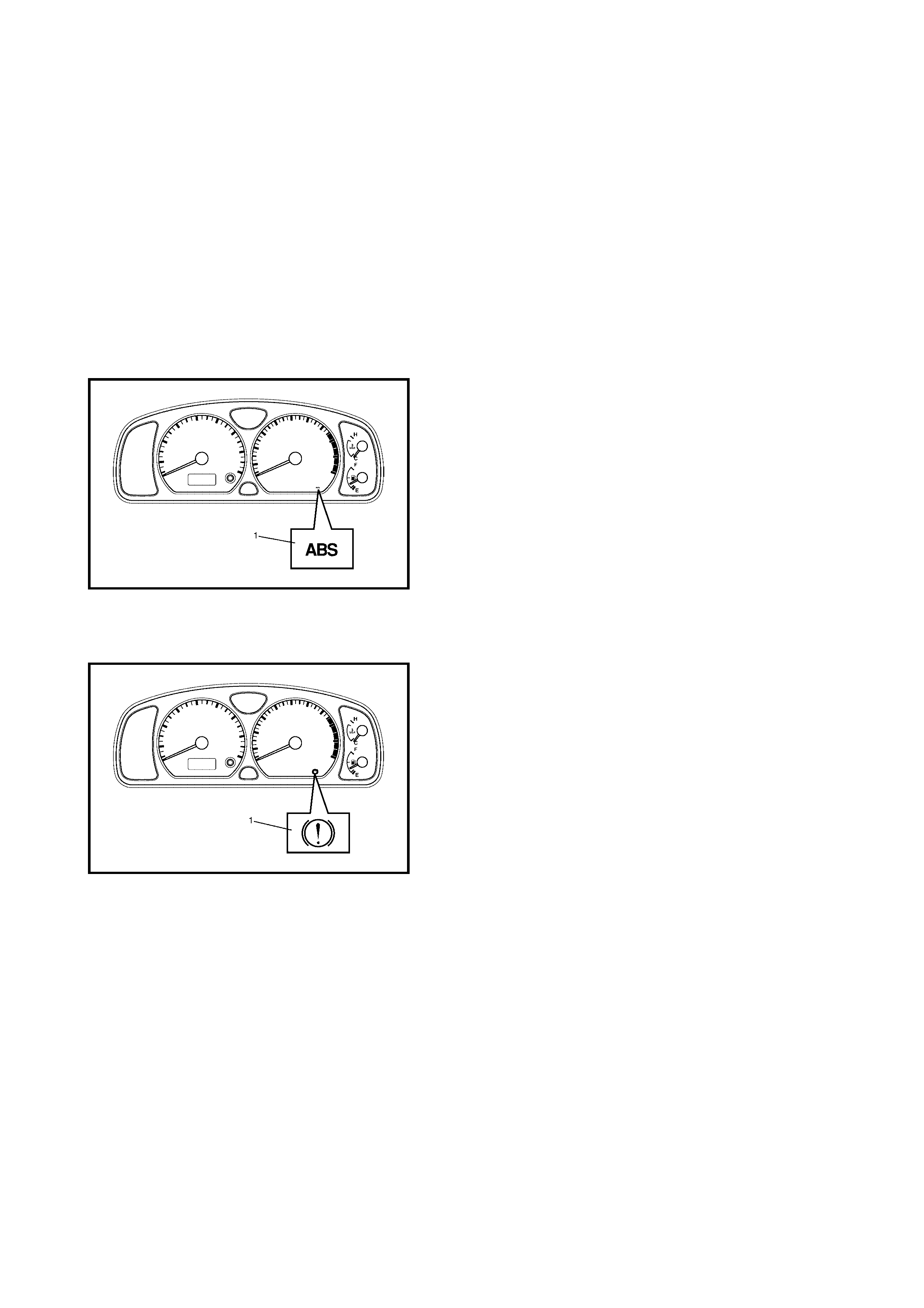
2.3 ABS WARNING LAMP CHECK
1. Turn ignition switch ON.
2. Check that the ABS warning lamp (1) comes ON for
about 2 seconds and then goes off.
If any faulty condition is found, advance to Diagnostic
Flow Table-A, B, C or D.
2.4 EBD (BRAKE) WARNING LAMP CHECK
NOTE: Perform this check on a level place.
1. Turn ignition switch ON with parking brake applied.
2. Check that EBD warning lamp (brake warning lamp)
(1) is turned ON.
3. Release parking brake with ignition switch ON and
check that EBD warning lamp (brake warning lamp)
goes off.
If it doesn’t go off, go to TABLE-E in this Section.
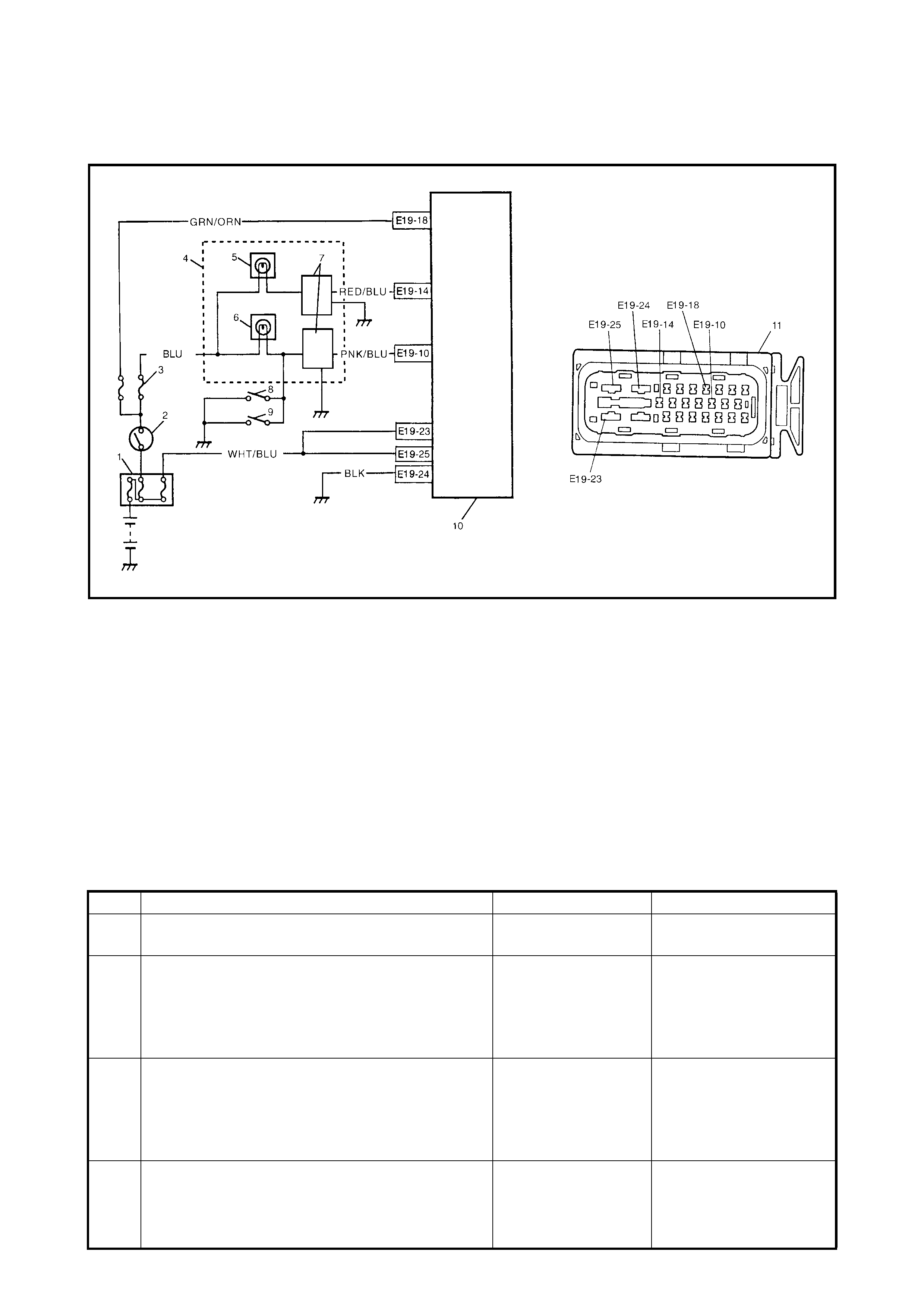
2.5 TA BLE – A ABS WARNING LAMP CIRCUIT CHECK
LAMP DOES NOT COME ON AT IGNITION SWITCH ON
Legend
CIRCUIT DESCRIPTION
Operation (ON/OFF) of the ABS warning lamp is controlled by the ABS control module through the lamp
driver module in the combination meter.
If th e Antilo ck b rake syste m is in good cond ition, the A BS co ntrol modul e turn s the ABS warnin g lamp ON at
ignition switch ON, keeps it ON for 2 seconds and th en turns it OFF. If a fault in the system is detected, the
ABS warning lamp is turned ON continuously by the ABS control module. Also, it is turned ON continuously by
the lamp driver module when the connector of the ABS control module is disconnected.
INSPECTION
1. Main fuse 5. ABS warning lamp 9. Brake fluid level switch
2. Igniti on swi tch 6. Brake (EB D) warni ng lam p 10. ABS hydraul ic unit/con tr ol mod ule asse mbl y
3. Circuit fuse 7. Lamp driver module 11. ABS hydraulic unit/control module connector
4. Combination meter 8. Parking brake switch
Step Action Yes No
1 Turn ignition switch ON.
Do other warning lamps come ON? Go to Step 2. Go to Step 4.
2 Disconnect the ABS hydraulic unit/control module
connector.
Does ABS warning lamp light with ignition switch
ON?
Substitute a known-
good ABS hydraulic
unit / control module
assembly and
recheck.
Go to Step 3.
3 Remove combination meter.
Is bulb of ABS warning lamp in good condition? RED/BLU circuit
shorted to ground. If
OK, replace combi-
nation meter (lam p
driver module).
Replace bulb.
4
Is IG fuse in good condition? Open i n BLK/WHT
wire to combination
meter or poor con-
nection.
Repair and repl ac e .

2.6 TABLE – B ABS WARNING LAMP CIRCUIT CHECK LAMP COMES ON STEADY
Refer to TABLE – A for System Circuit Diagram and Circuit Description.
INSPECTION
Step Action Yes No
1 Perform diagnostic trouble code check. Is there
any DTC (including code No.12, NO CODES on
Tech 2) exists?
Go to Step 2. Go to Step 3.
2 Does malfunction DTC (other than code No.12)
exist at Step 1? Go to Step 7 of ABS
DIAGNOSTIC FLOW
TABLE in this Sec-
tion.
Go to Step 3.
3 1. Disconnect ABS hydraulic unit/control
modu le con nector.
2. Check for proper connection to ABS
hydraulic unit/control module connector at
terminals E19-14, E19-18 and E19-24.
3. If OK then ignition switch ON and measure
voltage at terminal E19-18 of connector.
Is it 10 – 14 V?
Go to Step 4. GRN/ORN circuit open.
4 1. With ABS hydraulic unit/control module
connector disconnected, turn ignition switch
ON and light ABS warning lamp.
2. Connect ter mi nal E19- 14 of disco nne cte d
connector to ground using service wire.
Does ABS warning lamp turn off?
Go to Step 5. RED/BLU circuit open.
If wire and connection
are OK, replace combina-
tion
meter (lamp driver mod-
ule).
5 Measure resistance from connector terminal E19-
24 to body ground.
Is continui ty ind ic ate d?
Substitute a known-
good ABS hydraulic
unit/control module
assembly and
recheck.
BLK circui t open.
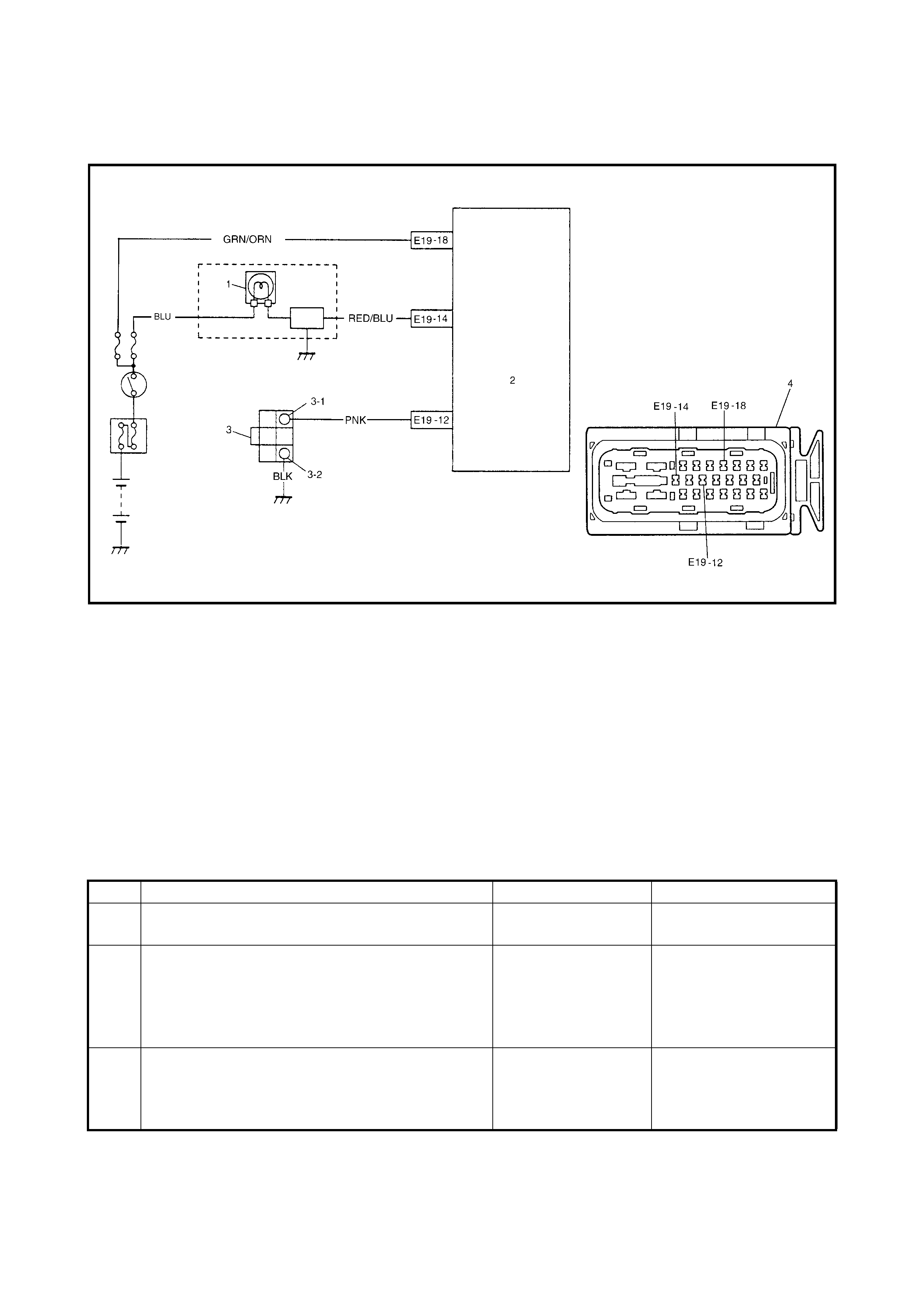
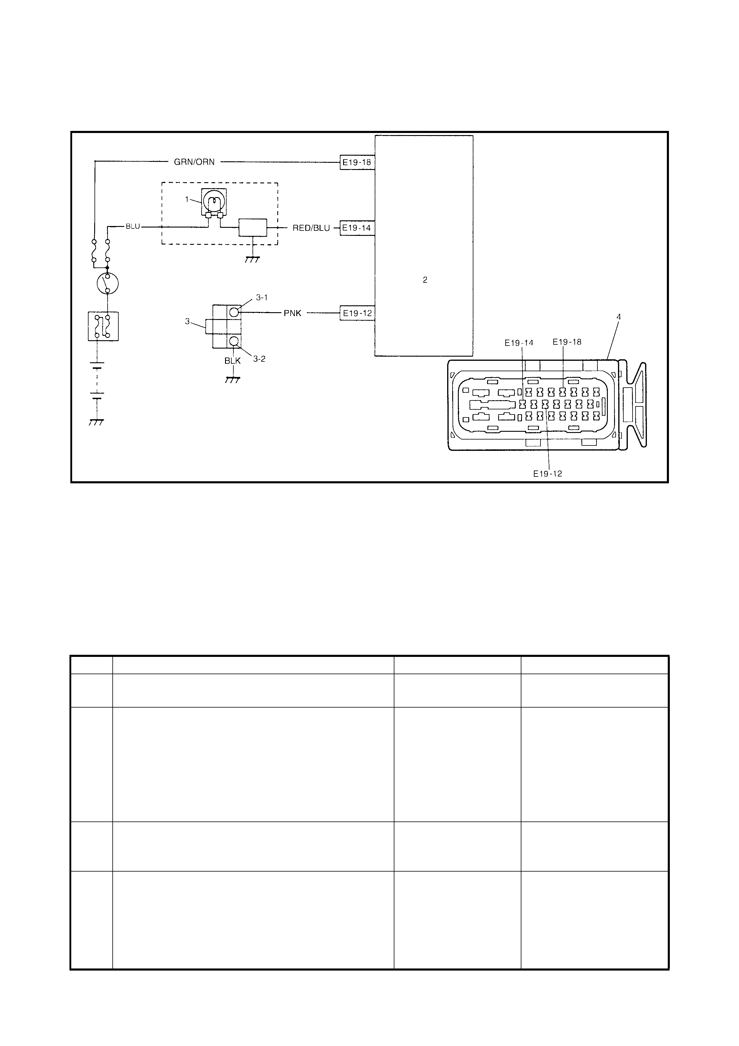
2.7 TABLE – C ABS WARNING LAMP CIRCUIT CHECK THE
LAMP FLASHES CONTINUOUSLY WHILE IGNITION SWITCH IS ON
Legend
CIRCUIT DESCRIPTION
When th e diagnos is swit ch terminal is short ed or connec ted to gr ound with the i gnition sw itch ON, d iagnosis
trouble code (DTC) is indicated by flashing of the ABS warning lamp only in the following cases.
• Normal DTC (12) is indicated if no malfunction DTC is detected in the ABS.
• A history malfunction DTC is indicated by flashing of the lamp if a current malfunction DTC is not detected
at that point although a history malfunction DTC is stored in memory.
INSPECTION
1. ABS warning lamp in combination meter 3-1. Diagnosis switch terminal
2. ABS hydraulic unit/control module assembly 3-2. Diagnosis ground terminal
3. Diagnosis connector No. 2 4. ABS hydraulic unit/control module connector
Step Action Yes No
1 Is diagnosis switch terminal connected to ground
via service wire? Go to Step 3. Go to Step 2.
2 1. Ignition switch ON.
2. Measure voltage between diagnosis switch
termin al and groun d.
Is it 10 – 14 V?
Substitute a known-
good ABS hydraulic
unit/control module
assembly and
recheck.
PNK wire circuit shorted
to ground.
3 1. Ignition switch ON.
2. Does flashing of ABS warning lamp indicate
DTC?
Go to Step 7 of ABS
DIAGNOSTIC FLOW
TABLE in this Sec-
tion.
Substitute a known-good
ABS hydraulic unit/con-
trol module assembly and
recheck.
2.8 TABLE – D CODE (DTC) IS NOT OUTPUT EVEN WITH DIAGNOSIS SWITCH
TERMINAL CONNECTED TO GROUND
Legend
CIRCUIT DESCRIPTION
When the diagnosis switch terminal is connected to ground with ignition switch turned ON, the ABS control
module outputs diagnostic trouble code by flashing ABS warning lamp.
INSPECTION
1. ABS warning lamp in combination meter 3-1. Diagnosis switch terminal
2. ABS hydraulic unit/control module assembly 3-2. Diagnosis ground terminal
3. Diagnosis connector No. 2 4. ABS hydraulic unit/control module connector
Step Action Yes No
1 Is it shorted diagnosis switch terminal and ground
terminal by service wire properly? Go to Step 2. Connect service wire
securely.
2 1. Disconnect service wire.
2. Disconnect ABS hydraulic unit/control
modu le con nector.
3. Measure resistance between diagnosis
switch terminal and connector terminal E19-
12.
Is it infinite (∞)?
PNK circuit open. Go to Step 3.
3 Measure resistance between ground terminal of
diagnosis connector No. 2 and body ground.
Is continui ty ind ic ate d?
Go to S tep 4. BLK circuit open or poor
connection.
4 1. Check for proper connection to ABS
hydraulic unit/control module at terminal
E19-12.
2. If OK, then check ABS warning lamp circuit
referring to TABLE A, B and C.
Is it in good condition?
Substitute a known-
good ABS hydraulic
with/control module
assembly and
recheck.
Repair ABS warning
lamp circ ui t.
2.9 TABLE – E EBD (BRA KE) WARNING LAMP
CHEC K LAMP COMES ON STEADY
CIRCUIT DESCRIPTION
The EBD warning lamp (brake warning lamp) is controlled by the parking brake switch, brake fluid level switch
and ABS control module/hydraulic unit assembly through the lamp driver module in the combination meter.
Refer to TABLE – A for circuit diagram.
INSPECTION
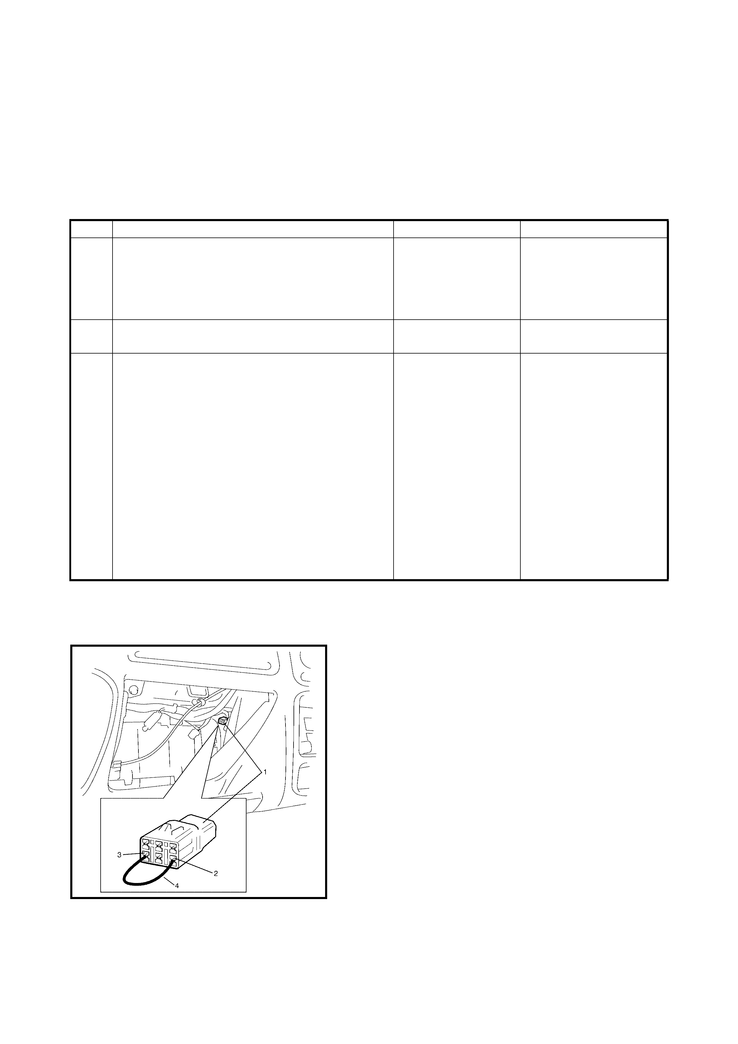
2.10 DIAGNOSTIC TROUBLE CODE (DTC) CHECK (USING ABS WARNING LAMP)
1. Perform ABS WARNING LAMP CHECK described
above.
2. Using service wire (4), connect diagnosis switch
terminal ( 2) of di agnos is conn ector No . 2 ( 1) to gr ound
(3).
3. Turn ignition switch ON.
4. Read flashing of ABS warning lamp which represents
DTC as shown in example below and write it down.
When more than 2 DTCs are stored in memory,
flashing for each DTC is repeated three times starting
with the smallest DTC number in increasing order.
For details of DTC, refer to DTC TABLE.
Step Action Yes No
1 1. Make sure that:
• Parking brake is completely released.
• Brake fluid level is upper than the minimum
level.
Are the check results OK?
Go to Step 2. Release parking brake
completely and/or replen-
ish brake fluid .
2 Does ABS warning lamp come on? Perform TABLE – B
previou sly outlin ed. Go to Step 3.
3 1. Disconnect ABS hydraulic unit/control
modu le con nector.
2. Check for proper connection to ABS
hydraulic unit/control module connector at
terminals E19-10.
3. If OK, apply chocks to wheels and select
gear in neutral position (P range for A/T).
4. Keep brake pedal depressed and start
engine.
Release parking brake.
5. Connect ter mi nal E19- 10 of disco nne cte d
connector to ground using service wire.
Does EBD warning lamp (brake warning lamp)
turn off?
Substitute a known-
good ABS hydraulic
unit/control module
assembly and
recheck.
PNK/BLU ci rcui t open.
If wire and connection
are OK, replace combina-
tion meter.
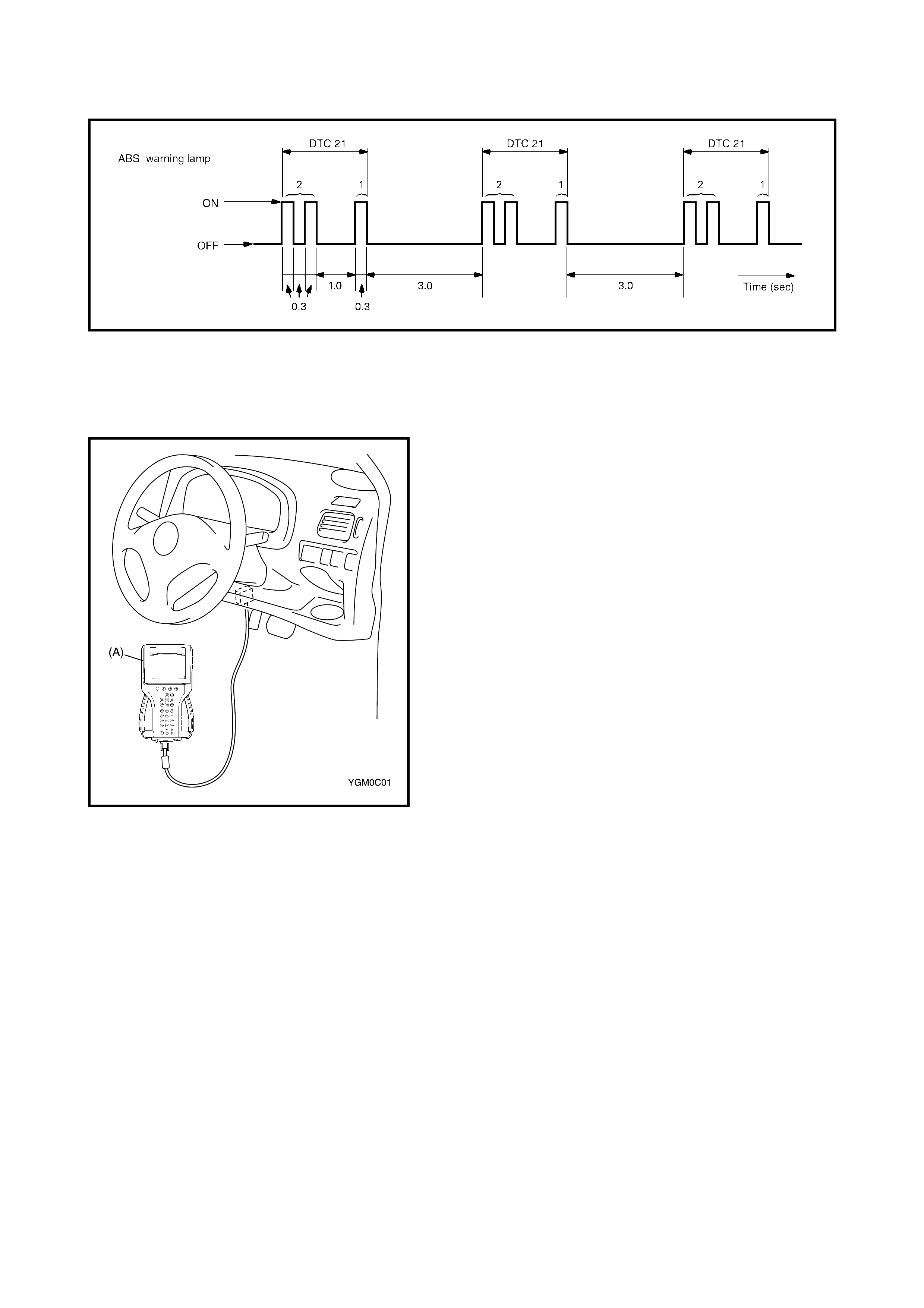
Example: When right-front wheel speed sensor circuit opens (DTC 21)
5. After comple ting the c heck, tur n ignitio n switc h off, dis-
connect service wire from the diagnosis connector
No.2.
2.11 DIAGNOSTIC TROUBLE COD E (D TC) CHECK (USING TECH 2 )
1. After setting the cartridge for ABS to Tech 2, (A)
connect Tech 2 to the data link connector.
2. Turn ignition switch ON.
3. Read DTC a ccordin g to instruc tions di spla yed o n Tech
2 and print it or write it down. Refer to Tech 2
operator’s manual for further details.
4. After completi ng the check, tur n ignition swi tch off and
disconnect Tech 2 from DLC.
2.12 DIAGN OSTIC TROUBLE CODE (DTC) CLEARANC E
WARNING:
When performing a driving test, select a
safe place where there is neither any traffic nor any
traffic accident possibility and be very careful dur-
ing testing to avoi d oc cu rren ce of an ac c ide n t.
After repair or replace of faulty part(s), clear all DTCs by
performing the following procedure.
1. Turn ignition switch OFF.
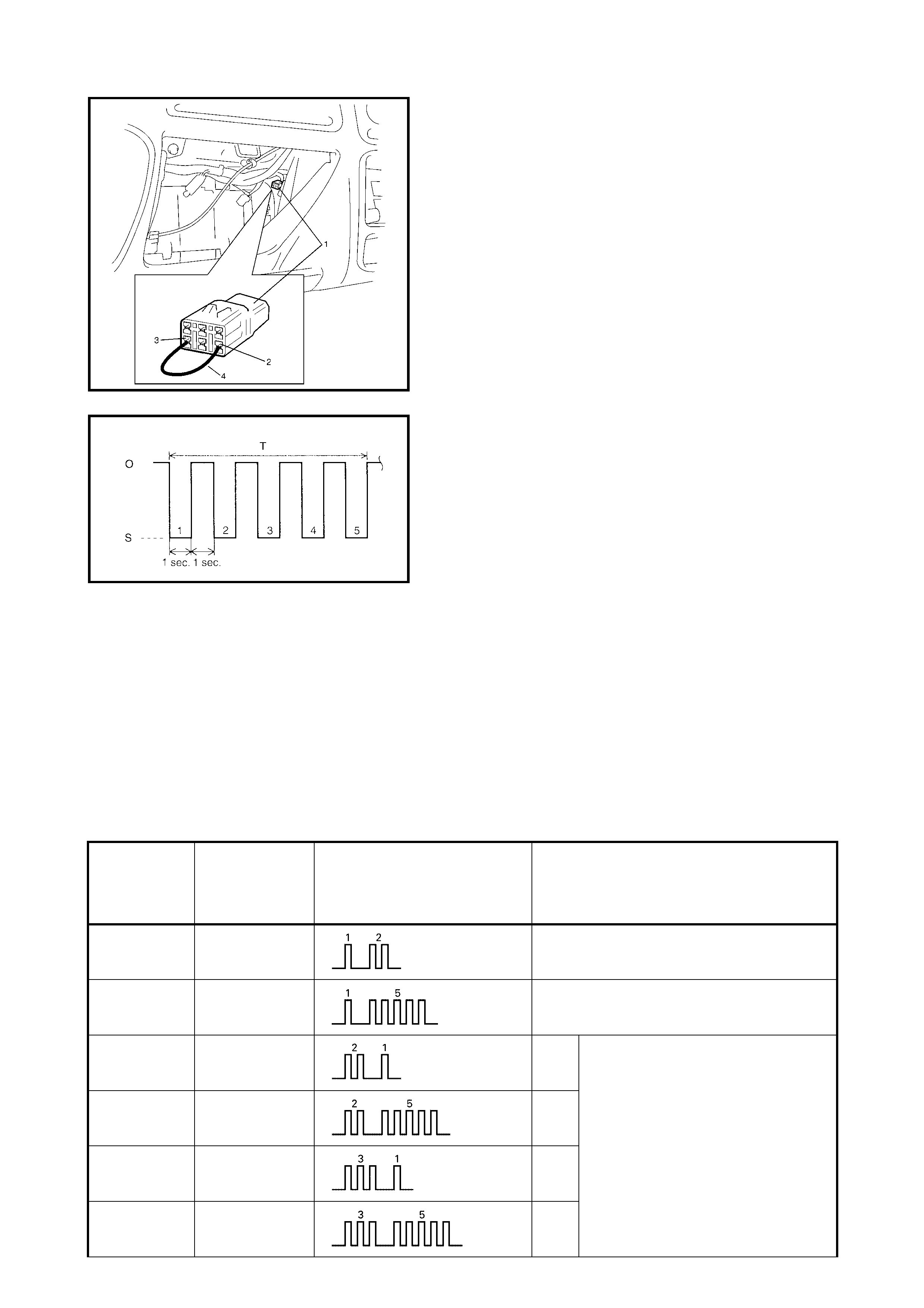
2. Using service wire (4), connect diagnosis switch
terminal ( 2) of di agnos is conn ector No . 2 ( 1) to gr ound
terminal (3).
3. With connection described in above Step 2) main-
tained, turn ignition switch ON.
4. Repeat disconnecting and reconnecting of service wire
between diagnosis and ground terminals 5 times or
more at about 1 sec. interval within 10 seconds.
Legend
5. Turn ignition switch OFF and disconnect service wire
from the diagnosis connector No.2.
6. Perform DRIVING TEST (Step 2 of ABS DIAGNOSTIC
FLOW TABLE in this Section) and DTC CHECK and
confirm that normal DTC (DTC 12) is displayed; not a
malfuncti on DTC.
NOTE: It is also possible to clear DTC by using Tech 2.
Refer to Cartridge Manual for procedure to clear DTC.
2.13 DIAGNOSTIC TROUBLE CODE (DTC) TA BLE
CAUTION:
Perform ABS DIAGNOSTIC FLOW TABLE before starting diagnosis.
O: Open
S: Short
T: About 10 secon ds
DTC
(displayed
on Tech 2)
DTC
(indicated by
ABS warning
lamp)
ABS warning lamp flashing
pattern DIAGNOSTIC ITEMS
NO DTC 12 Normal
C1015 15 G-sensor circuit
C1021 21 RF Wheel speed sensor circuit
C1025 25 LF
C1031 31 RR
C1035 35 LR
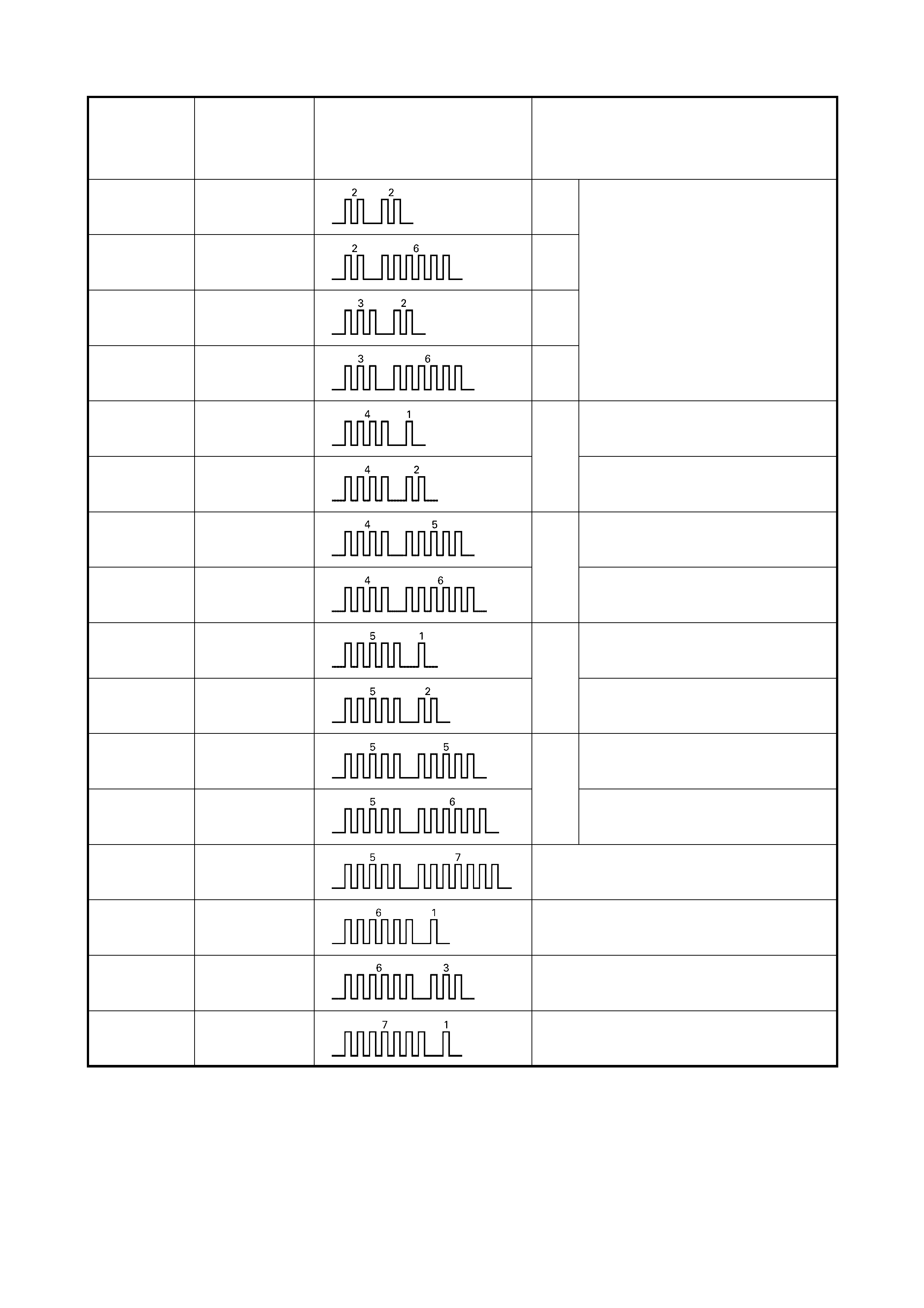
C1022 22 RF Wheel speed sensor circuit
or sensor ring
C1026 26 LF
C1032 32 RR
C1036 36 LR
C1041 41 RF Inlet solenoid valve circuit
C1042 42 Outlet solenoid valve circuit
C1045 45 LF Inlet solenoid valve circuit
C1046 46 Outlet solenoid valve circuit
C1051 51 RR Inlet solenoid valve circuit
C1052 52 Outlet solenoid valve circuit
C1055 55 LR Inlet solenoid valve circuit
C1056 56 Outlet solenoid valve circuit
C1057 57 Power source
C1061 61 ABS pump motor and/or motor relay circuit
C1063 63 Fail safe-relay
C1071 71 ABS cont rol module
DTC
(displayed
on Tech 2)
DTC
(indicated by
ABS warning
lamp)
ABS warning lamp flashing
pattern DIAGNOSTIC ITEMS
2.14 DTC C1 015 (DTC 15) – G-SENSOR CIRCUIT
Legend
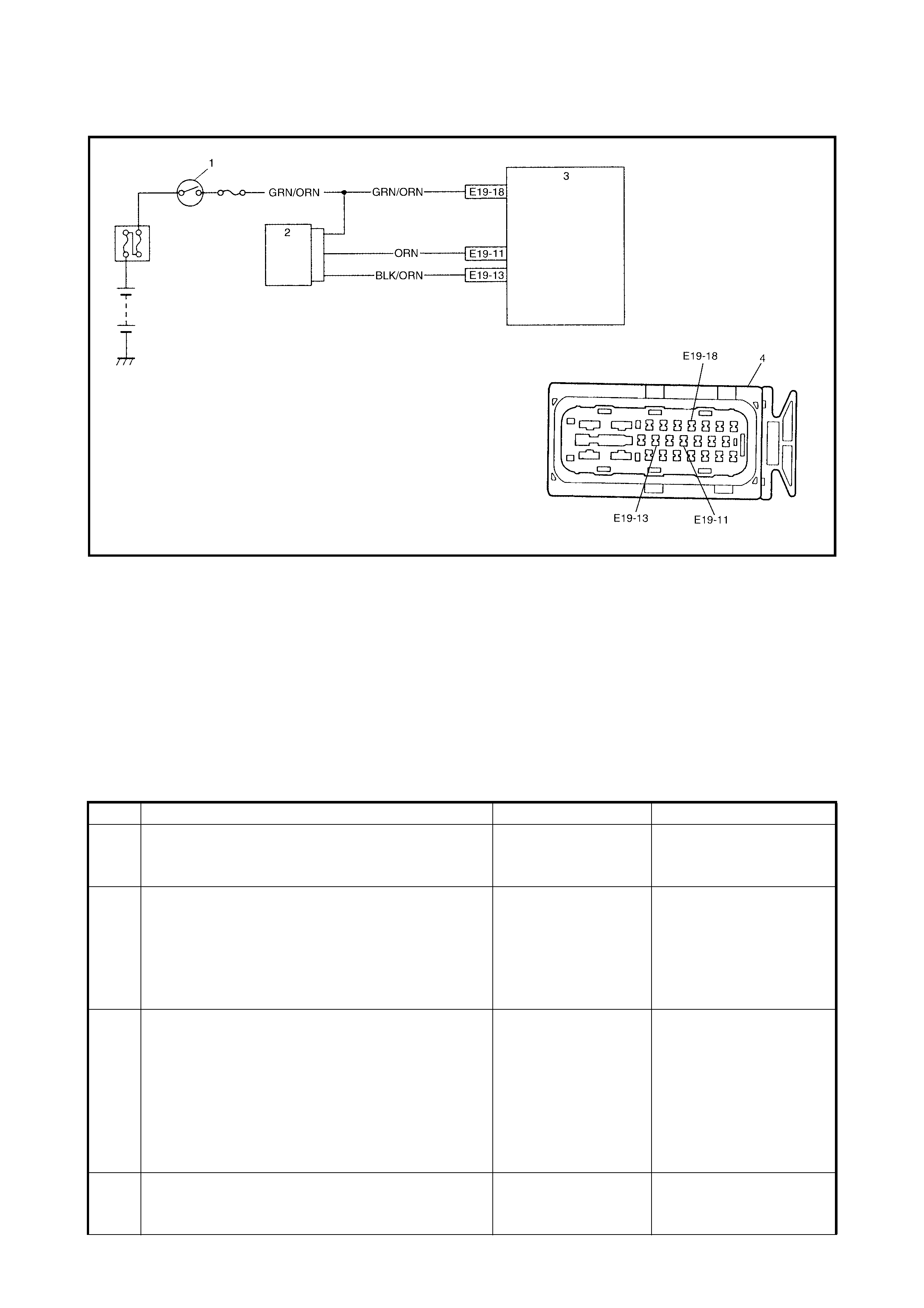
DESCRIPTION
While the v ehicle is st oppe d or r unnin g, if the po tential d ifference betwee n the senso r s ignal te rmina l E1 9-11
and the sens or g round te rmin al E1 9-13 is n ot with in the spec ifie d voltage value, or if the signa l vo ltage whil e
stopped does not vary from that while running, this DTC is set.
Therefore, this DTC may be set when a vehicle is lifted up and its wheel(s) turned. In such case, clear the
DTC and check again.
INSPECTION
1. Ignition switch 3. ABS hydraulic unit/control module assembly
2. G-sensor 4. ABS hydraulic unit/control module connector
Step Action Yes No
1 Is G-sensor installed floor securely? Go to Step 2. Tighten sensor or bracket
screw securely. If not,
using new screw.
2 1. Ignition switch OFF.
2. Remove G-sensor with bracket.
3. Check for proper connection to G-sensor.
4. If OK then check G-sensor referring to
INSPECTION of G-SENSOR.
Is it in good condition?
Go to S tep 3. Replace G-sensor.
3 1. Disconnect connectors from ABS hydraulic
unit/control module assembly and G-sensor.
2. Check for proper connection to ABS control
module at terminals E19-11 and E19-13.
3. If OK, turn ignition switch ON and measure
voltage between GRN/ORN terminal of
sensor connector and body ground.
It is 10 – 14 V?
Go to Step 4. GRN/ORN circuit open.
4 Measure voltage between ORN terminal of sensor
connector and body ground.
Is it 0 V?
Go to Step 5. ORN circuit shorted to
power circuit.
2.15 DTC C1021 (DTC 21), DTC C1022 (DTC 22) RIGHT-FRONT WHEEL SPEED
SENSOR CIRCUIT OR SENSOR RING DTC C1025 (DTC 25), DTC C1026 (DTC 26)
LEF T-FRONT WHEEL SPEED SENSOR CIRCUIT OR SENSOR RING DTC C1031 (DTC
31), DTC C1032 (DTC 32) RIGHT-REAR WHEEL SPEED SENSOR CIRCUIT OR
SENSOR RING DTC C1035 (DTC 35), DTC C1036 (DTC 36) LEFT-REAR WHEEL
SPEED SENSOR CIRCUIT OR SENSOR RING
Legend
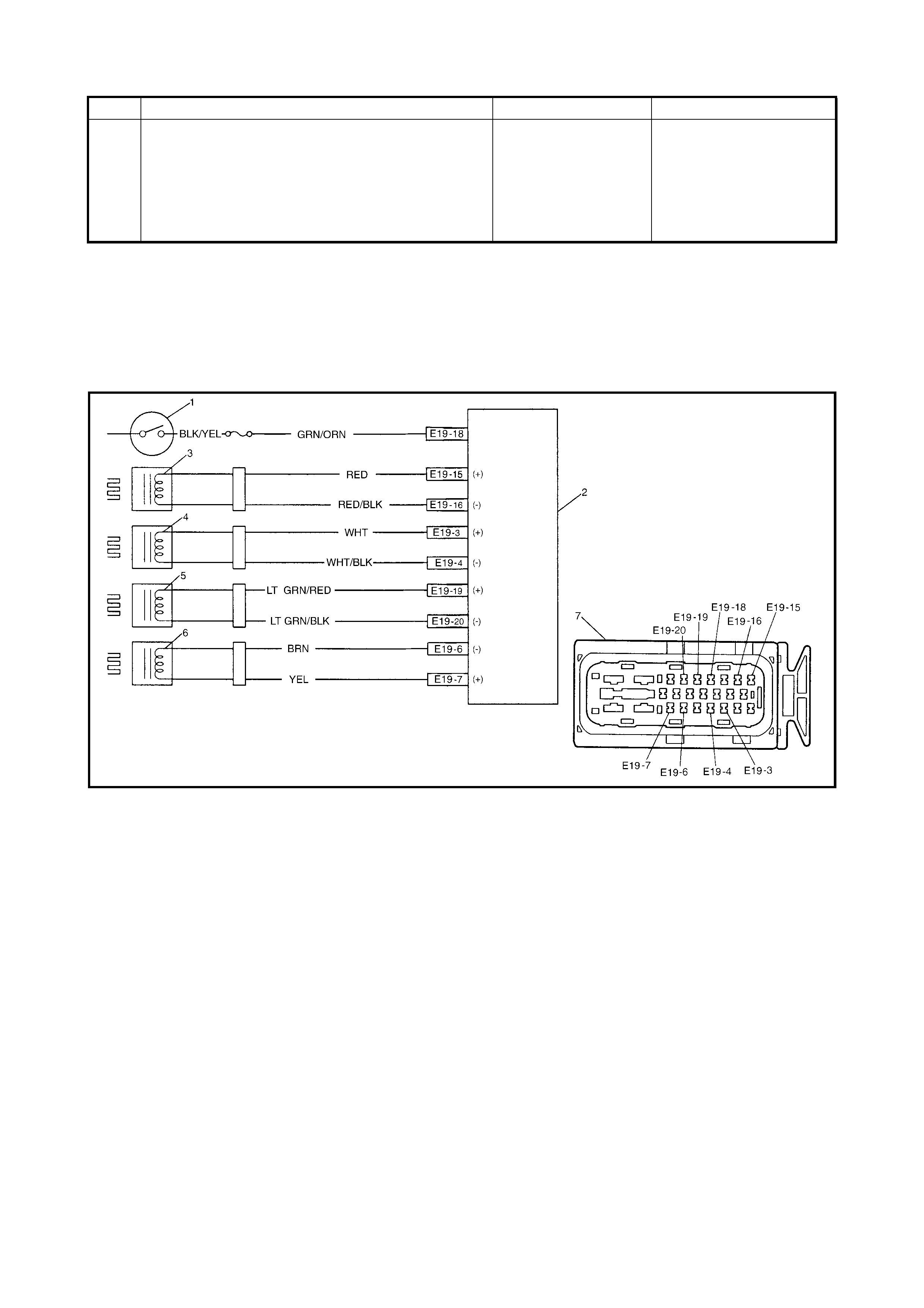
DESCRIPTION
The A BS control m odule monitors the voltage at th e terminal of e ach sensor while the igni tion switch is ON.
When the voltage is not within the specified range, an applicable DTC will be set. Also, when no sensor signal
is inputted at starting or while running, an applicable DTC will be set.
NOTE: When the vehicle was operated in any of the following ways, one of these DTCs may be set even
when the sensor is in good condition. If such possibility is suspected, repair the trouble (dragging of brake,
etc.) of the vehic le, clear DTC once and then after perfo rming the drivin g test as described in Step 2 of ABS
DIAGNOSIS FLOW TABLE, check whether or not any fault exists.
• The vehicle was driven with parking brake pulled.
• The vehicle was driven with brake dragging.
• Wheel spin occurred while driving.
• Wheel(s) was turned while the vehicle was jacked up.
• The vehicle was stuck.
5 1. Ignition switch OFF.
2. Check that ORN circuit is free from open or
short to ground and BLK/ORN circuit.
Is it in good condition?
BLK/ORN circuit
open. If circuit is OK,
substitute a known-
good ABS hydraulic
unit/control module
assembly.
ORN circuit open or
shorted to ground or
BLK/ORN circuit.
Step Action Yes No
1. Ignition switch 5. Left-rear wheel speed sensor
2. ABS control module/hydraulic unit assembly 6. Right-rear wheel speed sensor
3. Left-front wheel speed sensor 7. ABS hydraulic unit/control module connector
4. Right-front wheel speed sensor

INSPECTION
Step Action Yes No
1 1. Disconnect applicable ABS wheel speed
sensor connector with ignition switch OFF.
2. Measure resistance between terminals of
ABS wheel speed sensor. Refer to FRONT
WHEEL SPEED SENSOR and/or REAR
WHEEL SPEED SENSOR in this Section.
Is measured resistance value as specified?
Go to Step 2. Replace ABS wheel
speed sensor assembly.
2 1. Turn ignition swi tc h OFF.
2. Disconnect ABS hydraulic unit/control
modu le con nector.
3. Check for proper connection to ABS control
module at each sensor terminal.
4. If OK, then turn ignition switch ON and
measure voltage between sensor terminal of
module connector and body ground.
Is it 0V?
Go to Step 3. ABS wheel speed sen-
sor circuit shorted to
power.
3 1. Turn ignition swi tc h OFF.
2. Connect ABS wheel speed sensor
connector.
3. Measure resistance between the following
points.
4. Both ABS hydraulic unit/control module
connector terminals of the corresponding
sensor.
This check result should be the same as
above Step 1.
5. Either terminal of wheel speed sensor
connector and body ground.
This check result should be no continuity.
Are both check results OK?
Go to Step 4. Circuit open or shorted to
ground.
4 1. Remove applicable ABS wheel speed
sensor.
2. Check sensor for damage or foreign material
attached.
Is it in good condition?
Go to Step 5. Clean, repair or replace.
5 1. Check front and/or rear sensor ring for the
following (remove rear axle shaft as
necessary):
2. Ring serration (teeth) neither missing nor
damaged.
3. No foreign material being attached.
4. Ring not eccen tric .
5. Wheel bearing free from excessive play.
Are they in good condition?
Go to Step 6. Clean, repair or replace.
6 1. Install ABS wheel speed sensor to knuckle.
2. Tighten sensor bolt to specified torque and
check that there is no clearance between
sensor and knuckle.
Is it OK?
Go to Step 7. Replace ABS wheel
speed sensor.
7 Referring to Reference of FRONT WHEEL
SPEED SENSOR and/or Reference of REAR
WHEEL SPEED SENSOR in this Section, check
output voltage or waveform.
Is specified voltage and/or waveform obtained?
Substitute a known
good ABS hydraulic
unit/control module
assembly and
recheck.
Replace se ns or and
recheck.
2.16 DTC C10 41 (DTC 41) – RIGHT-FRONT INLET SOLENOID CIRCUIT, DTC C1045
(DTC 45) – LEFT-FRONT INLET SOLENOID CIRCUIT, DTC C1051 (DTC 51) – RIGHT-
REAR INLET SOLENOID CIRCUIT, DTC C1055 (DTC 55) – LEFT-REAR INLET
SOLENOID CIRCUIT, DTC C1042 (DTC 42) – RIGHT-FRONT OUTLET SOLENOID
CIRCUIT, DTC C1046 (DTC 46) – LEFT-FRONT OUTLET S OLENOID CIRCUIT, DTC
C1052 (DTC 52) – RIGHT-REAR OUTLET SOLENOID CIRCUIT, DTC C1056 (DTC 56) –
LEFT-REAR OUTLET SOLE NOID CIRCUIT
Legend
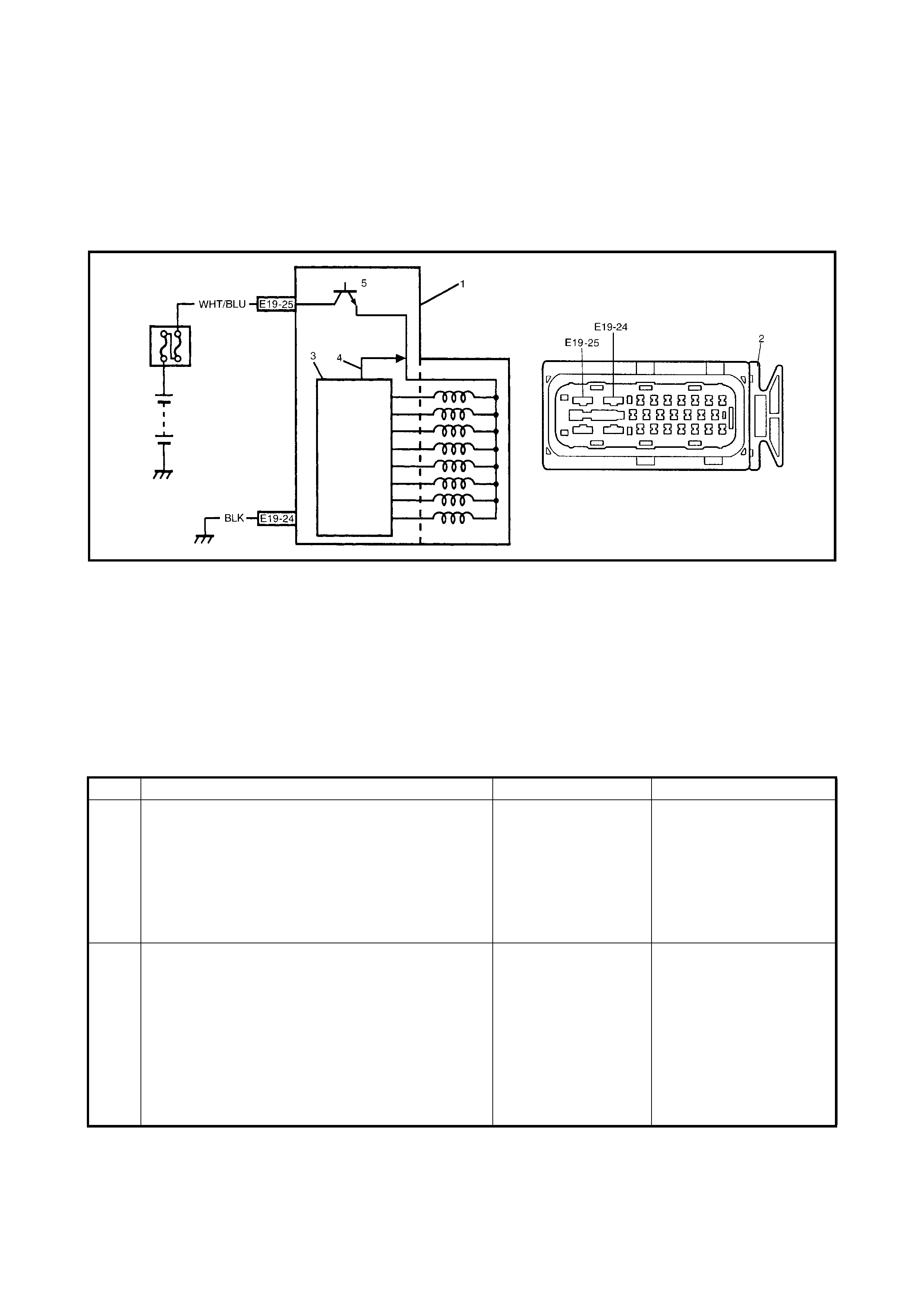
DESCRIPTION
The ABS control module monitors the output from the valve. When the output of each valve exceeds the spec-
ified value compared with the signal sent from ABS control module, this DTC is set.
INSPECTION
1. ABS hydraulic unit/control module assembly 4. Signal
2. ABS hydraulic unit/control module assembly connector 5. Fail-safe relay
3. ABS control module
Step Action Yes No
1 Check solenoid operation referring to item ABS
HYDRAULIC UNIT OPERATION CHECK in this
Section.
Is it in good condition?
Check terminal E19-
25 connection. If OK,
substitute a known
good ABS hydraulic
unit/control module
assembly and
recheck.
Go to Step 2.
2 1. Ignition switch OFF.
2. Disconnect ABS hydraulic unit/control
modu le con nector.
3. Check for proper connection to ABS
hydraulic unit/control module connector at
terminal E19-25.
4. If OK, measure voltage between terminal
E19-25 of module connector and E19-24.
Is it 10 – 14 V?
Substitute a known
good ABS hydraulic
unit/control module
assembly and
recheck.
WHT/B LU or BLK circuit
open.
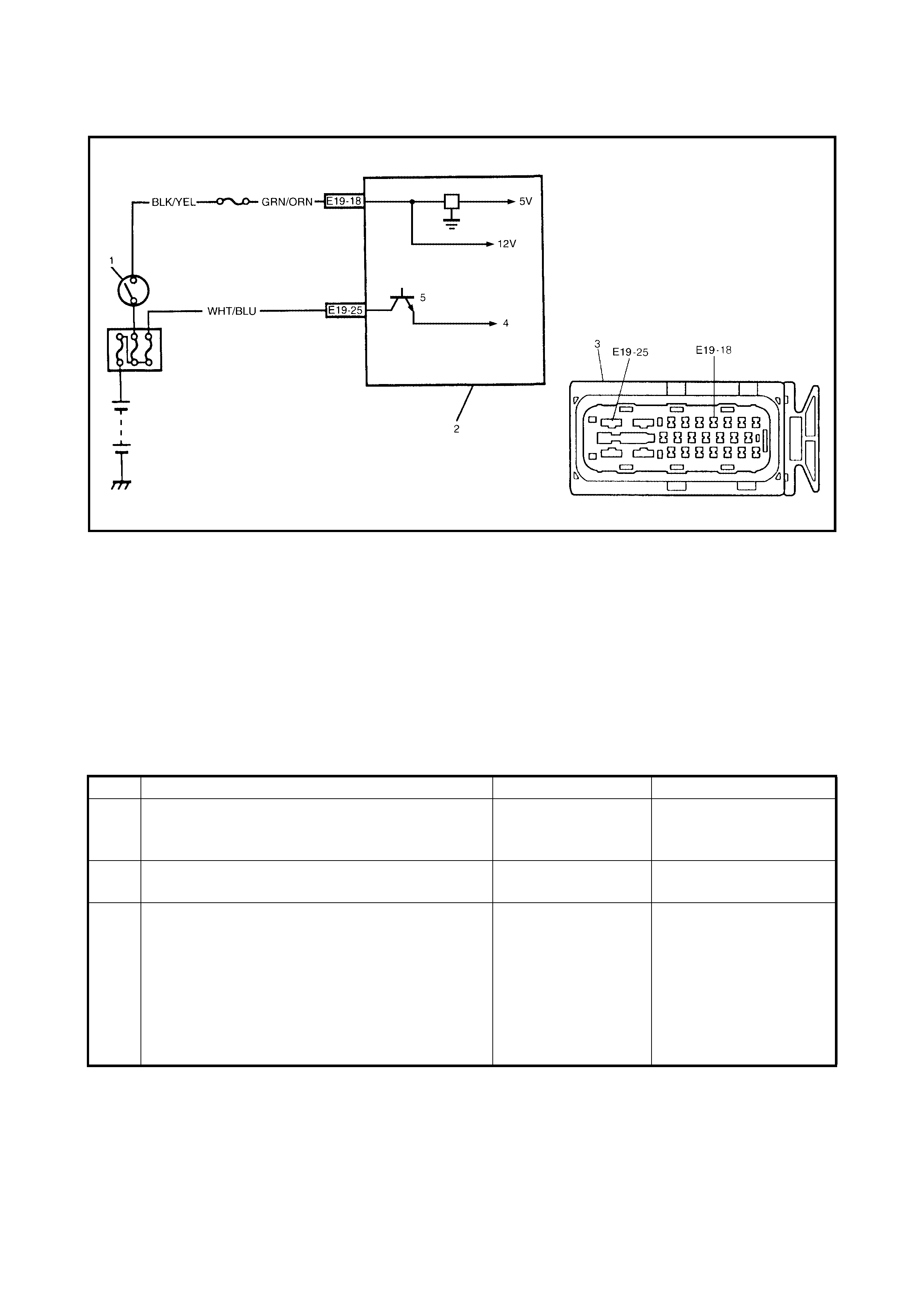
2.17 DTC C1057 (DTC 57 ) – POWER SOURCE CIRCUIT
Legend
DESCRIPTION
The AB S c ontrol mod ule moni tors the powe r sourc e vo ltage at ter mina l E1 9- 18. W hen the powe r sour ce vo lt-
age bec om es ex trem ely hig h o r lo w, this DT C w ill b e s et . A s so on as th e vol tage r ises o r lo wer s to the s peci-
fied level, the set DTC will be cleared.
INSPECTION
1. Ignition switch 3. ABS hydraulic unit/control module assembly
2. Main fuse 4. ABS hydraulic unit/control module connector
Step Action Yes No
1 1. Connect a voltmeter between battery
positive (+) terminal and body ground.
2. Start the engine a nd measure t he maximum
voltage when racing the engine.
Is it over 18V?
Check charging
system, refer to
Section 6H
CHARGING
SYSTEM.
Go to Step 2.
2 1. Disconnect ABS hydraulic unit/control
modu le con nector.
2. Keep the engine idling, measure the voltage
between terminal E19-18 of ABS control
modu le and bod y ground .
Is it always under 9V?
Check charging
system, refer to
Section 6H
CHARGING
SYSTEM.
Imperfect short
between wire GRN/
ORN and ground.
Poor connection of termi-
nal E19-18 or E19-24 of
the ABS control module.
If the above are in good
conditi on, su bs titu te a
known-good ABS
hydraulic unit/control
module and recheck.
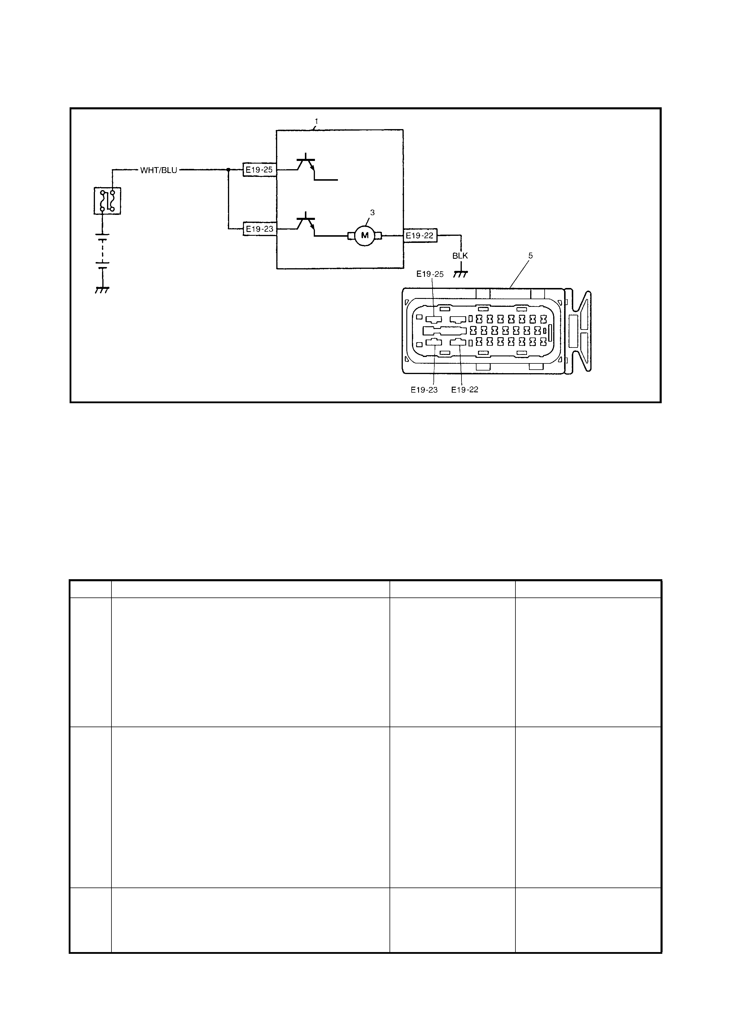
2.18 DTC C1061 (DTC 6 1) – ABS PUMP MOTOR CIRCUIT
Legend
DESCRIPTION
The ABS control module monitors the voltage at monitor terminal of pump motor circuit constantly with the
ignition switch turned ON. It sets this DTC when the voltage at the monitor terminal does not become high/low
according to ON/OFF commands to the motor relay of the module (does not follow these commands).
INSPECTION
1. ABS hydraulic unit/control module assembly 4. ABS fail safe relay
2. ABS pump motor relay 5. ABS hydraulic unit/control module connector
3. ABS pump motor
Step Action Yes No
1 Check pump motor referring to ABS HYDRAULIC
UNIT OPERATION CHECK in this Section.
Is it in good condition?
Check terminals E19-
25 and E19-23 con-
nection. If connec-
tions OK, substitute a
known-good ABS
hydraulic unit/control
module assembly
and rechec k.
Go to Step 2.
2 1. Ignition switch OFF.
2. Disconnect ABS hydraulic unit/control
modu le con nector.
3. Check for proper connection to ABS
hydraulic unit/control module connector at
terminal E19-23.
4. If OK, then measure voltage between
terminal E19-23 of module connector and
body ground.
Is it 10 – 14 V?
Go to Step 3. WHT/BLU circuit open.
3 Measure resistance between terminal E19-22 of
ABS hydraulic unit/control module connector and
body ground.
Is it infinite (∞)?
BLK circuit open. Substitute a known good
ABS hydraulic unit/con-
trol module assembly and
recheck.
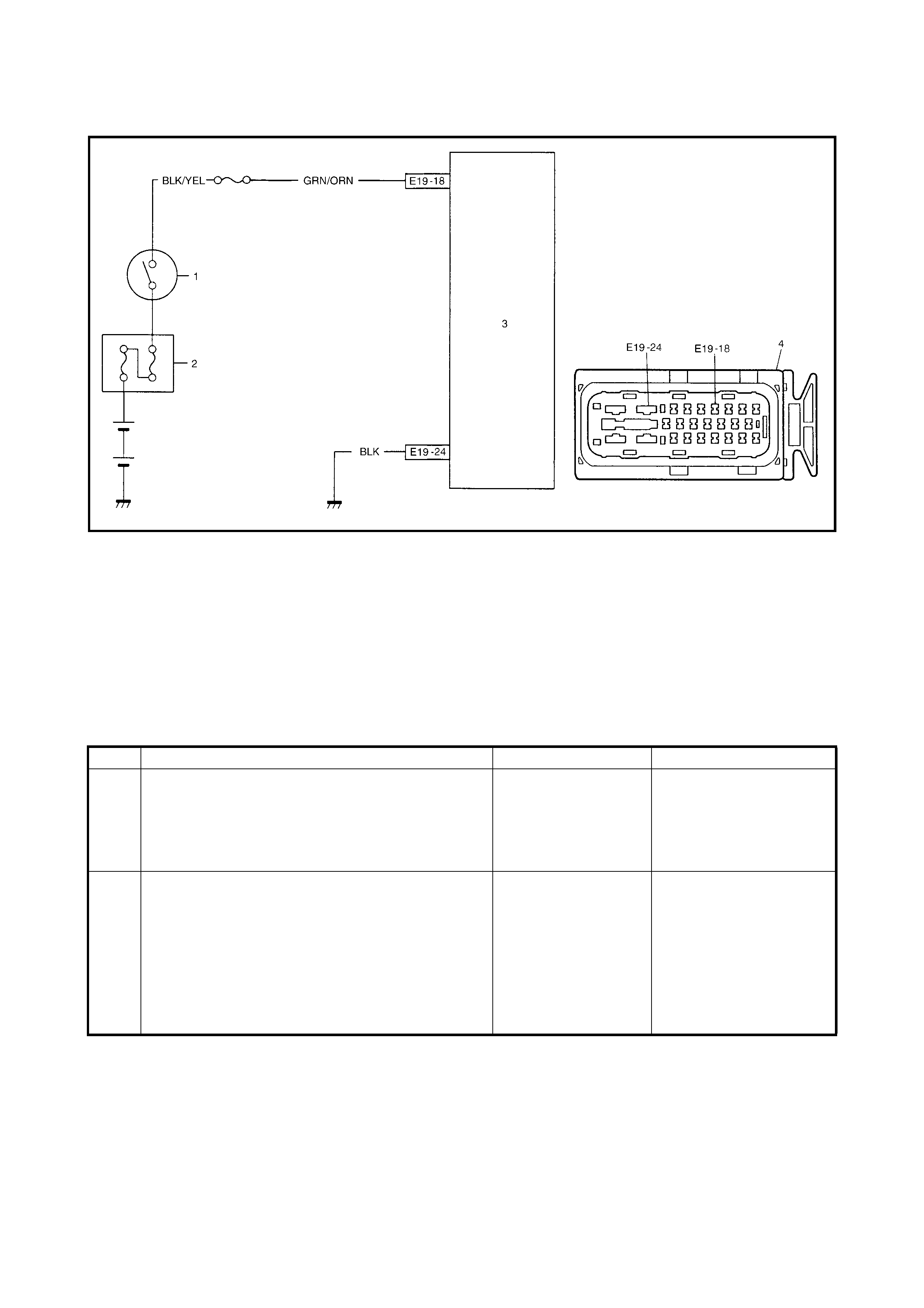
2.19 DTC C1063 (DTC 63) – ABS FAIL-SAFE RELAY CIRCUIT
Legend
DESCRIPTION
The ABS control module monitors the voltage at the terminal of the solenoid circuit constantly with ignition
switch turned ON. Also, immediately after the ignition switch is turned ON, perform an initial check as follows.
Switch fail-safe relay in the order of OFF → ON and check if voltage changes to Low → High. If anything faulty
is found in the initial check and when the voltage is low with ignition switch turned ON, this DTC will be set.
INSPECTION
1. Ignition switch 4. To solenoid valves
2. ABS hydraulic unit/control module assembly 5. Fail-safe relay
3. ABS hydraulic unit/control module connector
Step Action Yes No
1 Check battery voltage. Is it about 11 V or higher? Go to Step 2. Check charging system,
refer to Section 6H
CHARGING SYSTEM.
2 Check ABS main fuse and connection.
Is it in good condition? Go to S tep 3. Repair and/or replace
fuse.
3 1. Ignition switch OFF.
2. Disconnect ABS hydraulic unit/control
modu le con nector.
3. Check proper connection to ABS hydraulic
unit/control module at terminal E19-25.
4. If OK, then measure voltage between
connector terminal E19-25 and body ground.
Is it 10 – 14 V?
Substitute a known-
good ABS hydraulic
unit/control module
assembly and
recheck.
WHT/BLU circuit open or
short to ground.
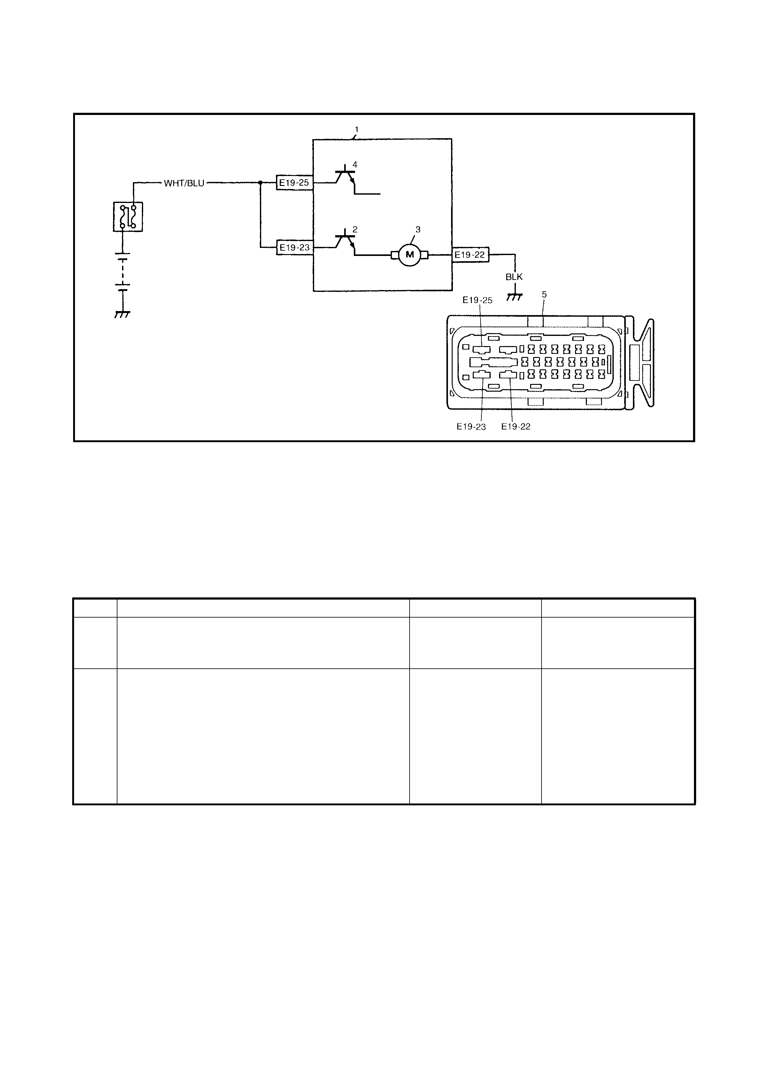
2.20 DTC C1071 (DTC 71) – AB S CONTROL MODULE
Legend
DESCRIPTION
This DTC will be set when an internal malfunction is detected in the ABS control module.
INSPECTION
1. ABS hydraulic unit/control module assembly 4. ABS fail safe relay
2. ABS pump motor relay 5. ABS hydraulic unit/control module connector
3. ABS pump motor
Step Action Yes No
1 Clear all DTCs and check DTC.
Is it DTC 71? Go to Step 2. Could be a temporary
malfu nct io n of the ABS
control module.
2 1. Check proper connection of ABS hydraulic
unit/control module connector.
2. If OK, disconnect ABS hydraulic unit/control
module connector and check the followings.
3. Voltage E19-25 terminal: 10 – 14 V
4. Resistance between E19-22 and body
ground: Continuity
Are the check result as specified above?
Replace ABS hydrau-
lic unit/control mod-
ule assembly.
Repair and recheck.

3. ON-VEHICLE SERVICE
3.1 PRECAUTIONS
While the connector is connected to the ABS hydraulic unit/
control module assembly, do not disconnect sensor con-
nector s wh il e th e ig ni tio n s witc h is O N as a DTC wil l b e s et
in ABS control module.
3.2 ABS HYDRAULIC UNIT OPERATION CHECK (US ING TECH 2)
1. Connect Tech 2 (A) to the data link connector (DLC) (1)
with ignition switch OFF.
2. Turn igni tion switch t o ON positi on and check ac tuator
operation using HYDRAULIC CONTROL TEST under
miscellaneous test (MISC. TEST) mode of Tech 2.
3.3 ABS HYDRAULIC UNIT OPE RATION CHECK (NOT USING TECH 2)
1. Check that the basic brake system other than ABS is in
good condition.
2. Check that battery voltage is 11 V or higher.
3. With the ABS warning lamp, check that no fault is
detected in the ABS. Refer to 2.10 DIAGNOSTIC
TROUBLE CODE (DTC) CHECK (USING ABS
WARNING LAMP) in this Section.
4. Lift up vehicle.
5. Set the transmission to neutral and release parking
brake.
6. Turn each wheel gradually by hand to check if brake
dragging occurs. If it does, correct.
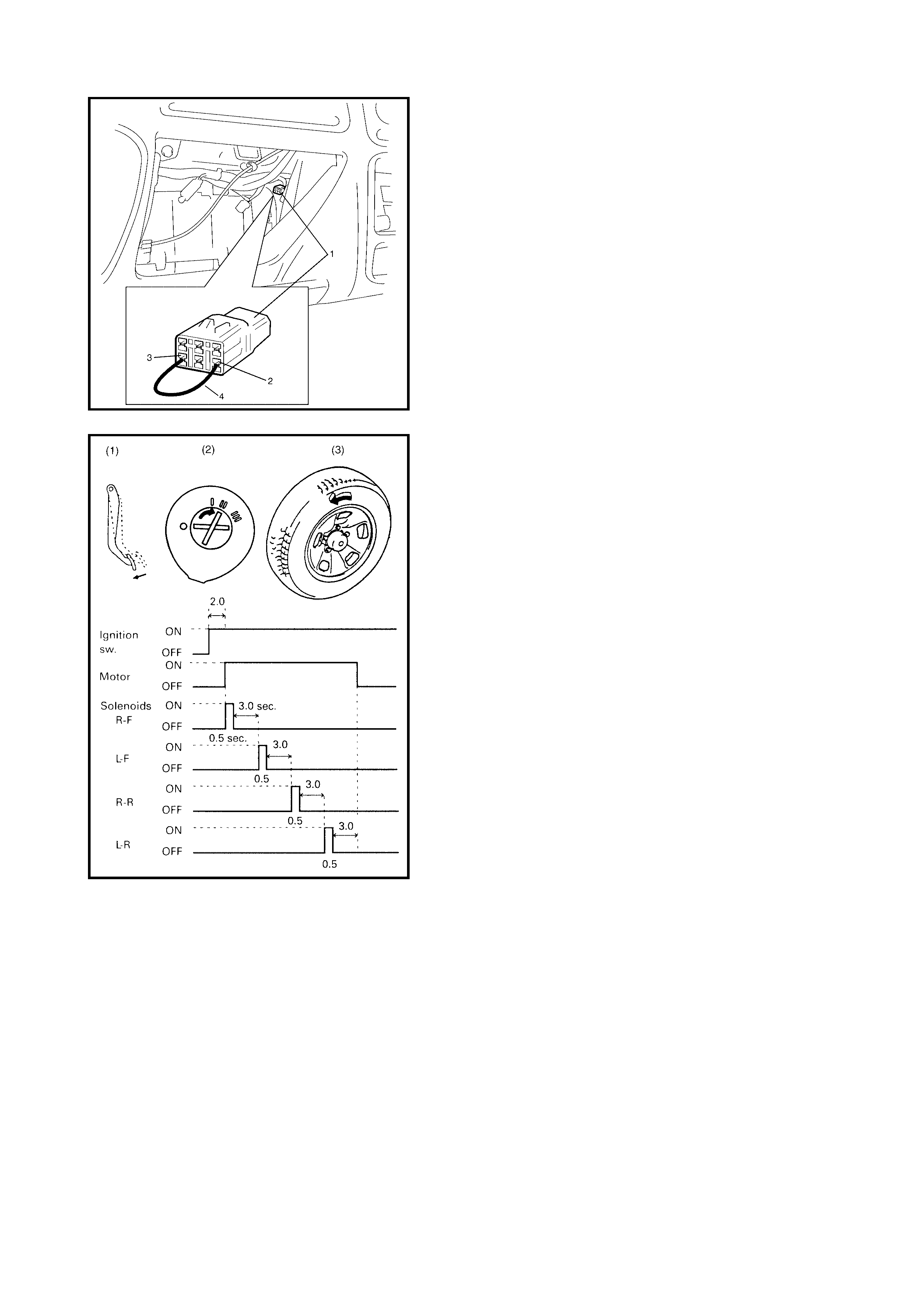
7. With diagnosis switch terminal (1) of the diagnosis
connector No. 2 (2) connected to ground terminal (3)
using service wire (4), turn ignition switch ON and
check if the ABS warning lamp indicates DTC 12.
If malfunction DTC is indicated, repair it first.
8. Turn ignition switch OFF.
9. Perform the following checks with the help of another
person.
Brake pedal (1) should be depressed and then the
ignition switch (2) turned ON by one person. A wheel
(3) should be turned by another person. At this time,
check that:
•Operat ion sound of so lenoid is hea rd and wheel tur ns
only about 0.5 sec. (Brake force is depressurised).
•Operation sound of pump motor is heard and pulsation
is felt at brake pedal.
10. If all four wheels cannot be checked during one ignition
cycle (OFF → ON), repeat Steps 8 and 9 until all four
wheels are checked.
If a faulty con dition is foun d in Steps 9 and 10, r eplace
the hydraulic unit/control module assembly.
11. Turn the ignition switch OFF and remove service wire
from the diagnosis connector No. 2.
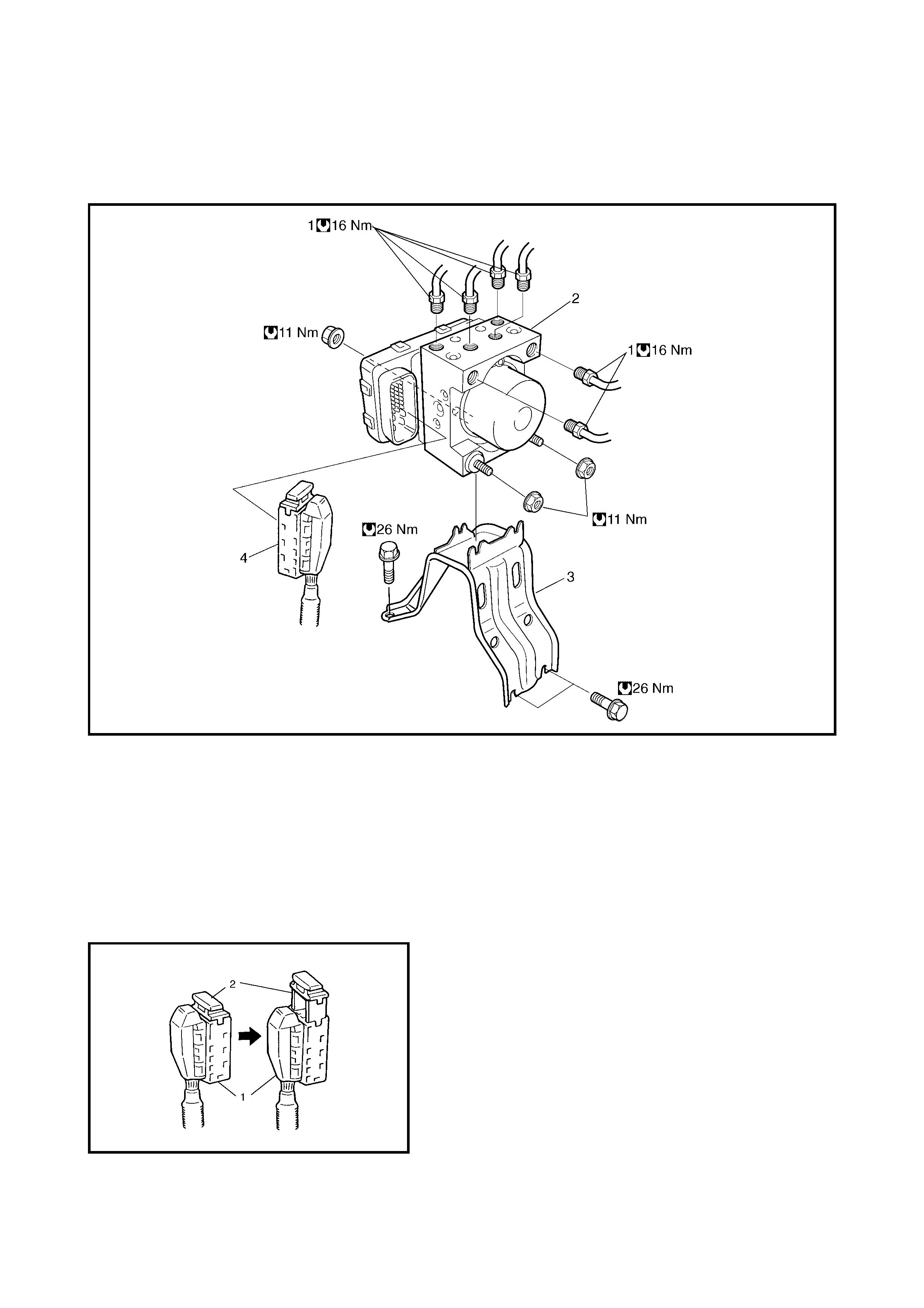
3.4 ABS HYDRAULIC UNIT/CONTROL MODULE AS SEMBLY
CAUTION:
Neve r di sa sse mbl e th e AB S hy dra ul ic un i t/c on t r ol mo du le as sem bl y, loose n b l in d pl ug
or remove motor. Performing any of these prohibited services will affect original performance of
the ABS hydraulic unit/control module assembly.
Legend
HYDRAULIC UNIT INSPECTION
Check hydraulic unit for fluid leakage.
If any, repair or replace.
REMOVAL
1. Disconnect negative cable from battery.
2. Disconnect the ABS hydraulic unit/control module
assembly connect or (1) by pulling up lock (2).
1. Brak e pip e 3. Bra cket
2. ABS hy dr aulic unit/c on tr ol mod ule asse mbly 4. Con nec tor
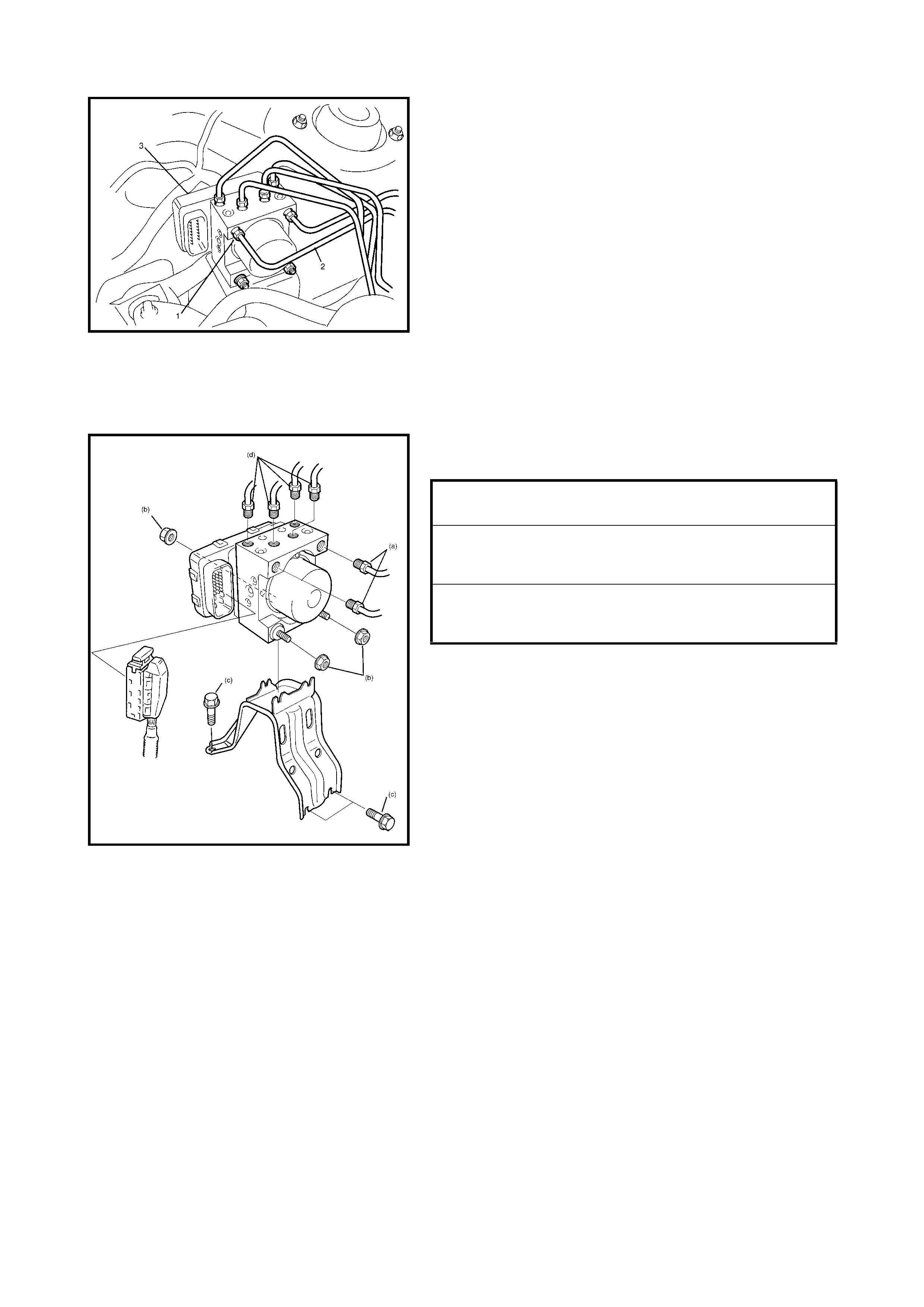
3. Using special tool 09950-78220, loosen flare nuts (1)
and disconnect the brake pipes (2) from the ABS
hydraulic unit/control module assembly (3).
NOTE: Put bleeder plug cap ont o the pipe to prevent fluid
from spill ing. Do n ot al lo w br ake flu id t o get o n painte d su r-
faces.
4. Remove the th ree nuts and remo ve the ABS hydraul ic
unit/control module assembly from the bracket.
CAUTION:
• Do not impact the hydraulic unit.
• Use care not to allow dust to enter the hydraulic
unit.
• Do not place the hydraulic unit on its side or
upside down. Handling it in an inappropriate way
will affect its original performance.
INSTALLATION
1. Install the hydraulic unit/control module assembly by
reversing removal procedure.
2. Bleed air from the brake system, refer to
Section 5 BRAK ES.
Check each installed part for fluid leakage and perform
3.2 ABS HYDRAUL IC UNIT OPERATION C HECK (USING
Tech 2) or 3.3 ABS HYDRAULIC UNIT OPERATION
CHECK (NOT USING Tech 2) in this Sec tio n.
NOTE: For a new ABS hydraulic unit/control module
assembly, if the ABS HYDRAULIC UNIT OPERATION
CHECK procedure has not been performed, the ABS
warning lamp may flash when the ignition is turned ON.
Accordingly preform A BS HYDRAULIC UNIT OPERATION
CHECK to stop flashing of the ABS warning lamp.
BRAKE PIPE FLARE NUT (a) TORQUE
SPECIFICATION 16 Nm
ABS HYDRAULIC UNIT / CONTROL
MODULE ASSEMBL Y NUT (b) TORQUE
SPECIFICATION 11 Nm
ABS HYDRAULIC UNIT / CONTROL
MODULE ASSEMBLY BRACKET BOLT
(c) TORQUE SPECIFICATION 26 Nm
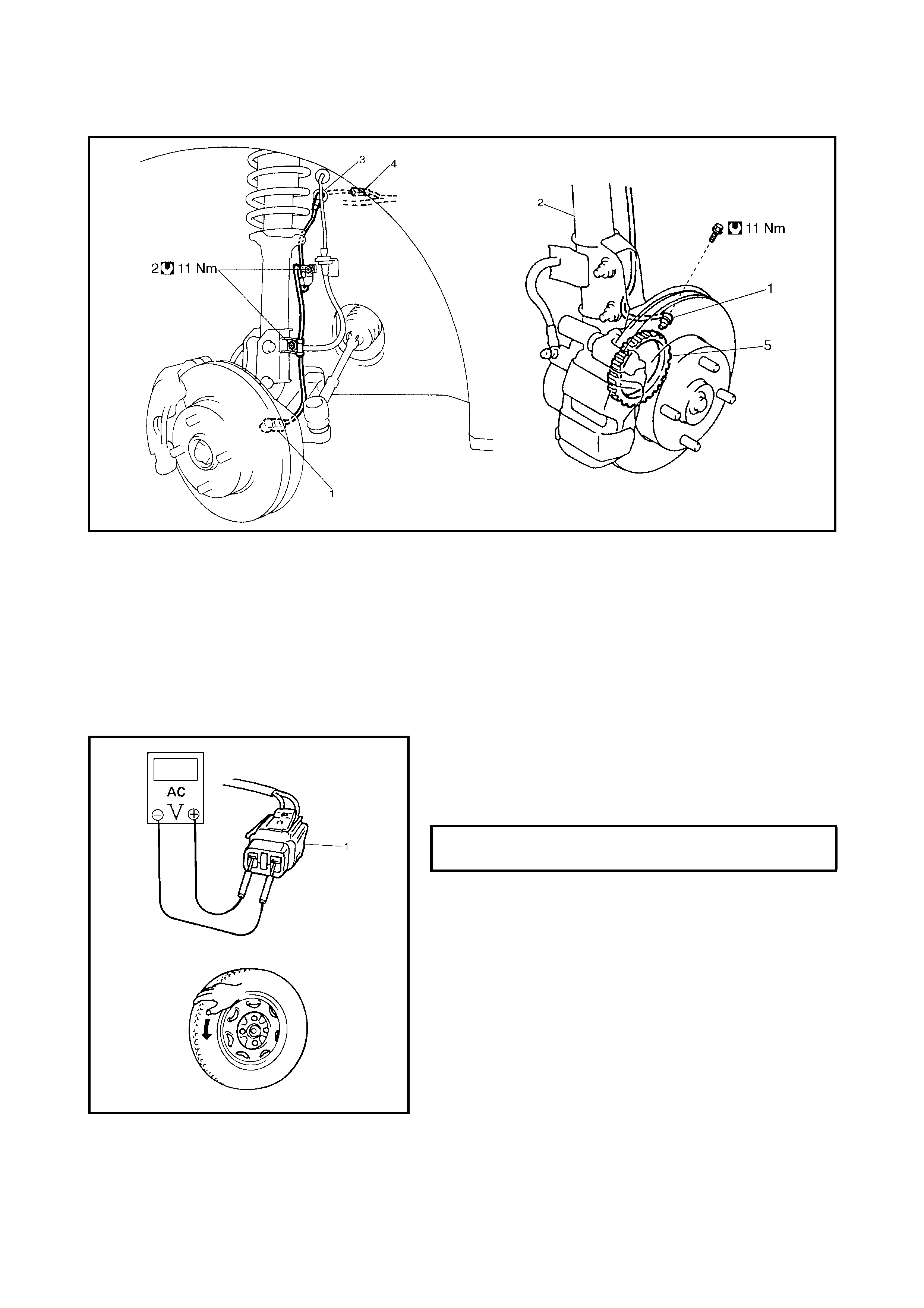
3.5 FRONT WHEEL SPEED SENSOR
Legend
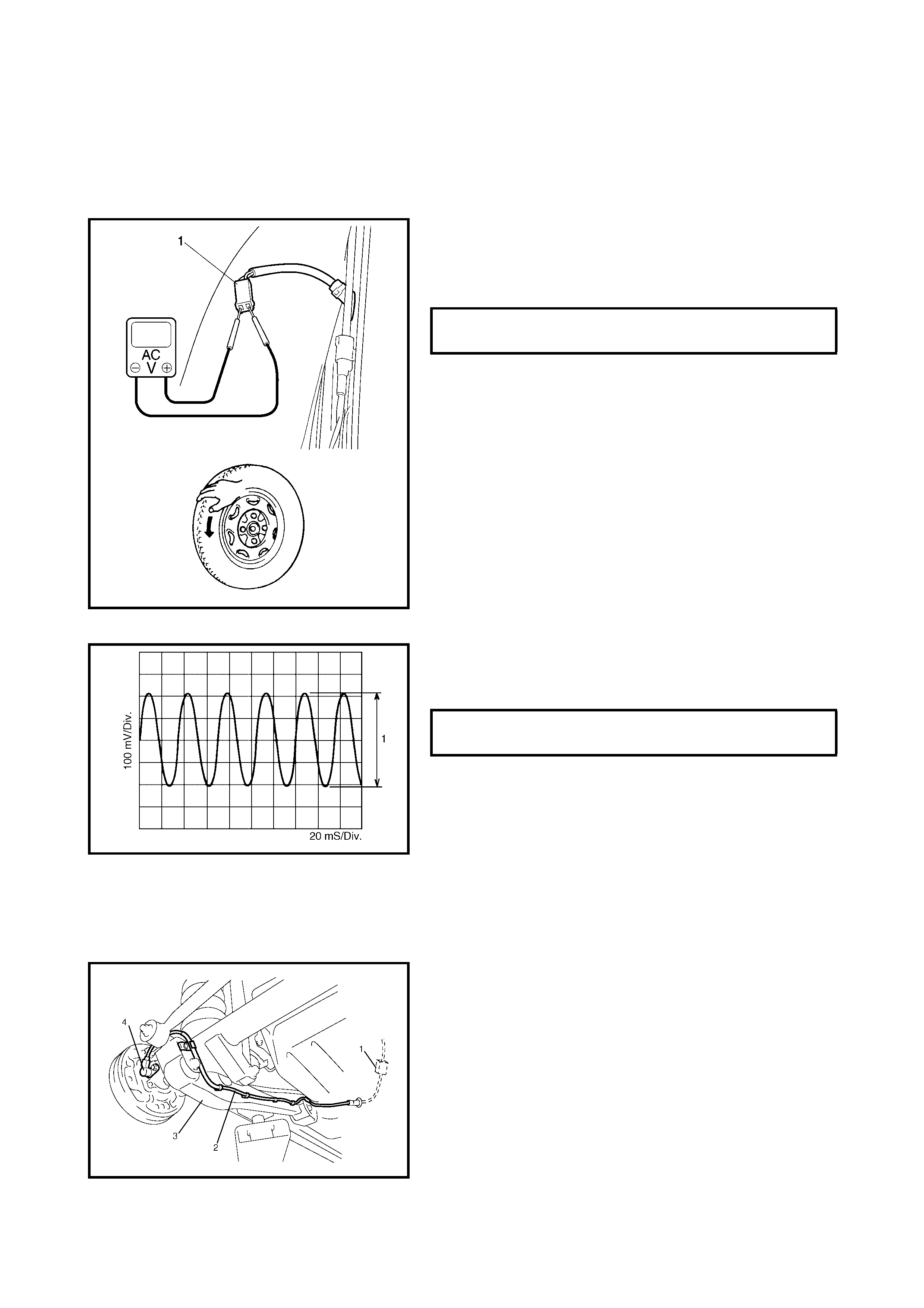
OUTPUT VOLTAGE INSPECTION
1. Turn ignition switch OFF.
2. Hoist vehicle a little.
3. Disconnect the wheel speed sensor connector.
4. Disconnect the wheel speed sensor grommet from
vehicle body.
5. Connect voltmeter between connector (1) terminals.
6. While turning the wheel by hand at a speed of approxi-
mately 1/2 rotation to 1 rotation p er second, check AC
voltage of sensor.
7. If measured voltage is not as specified, check sensor,
ring and its installation conditions.
1. Left front wheel speed sensor 3. Grommet 5. Sensor ring
2. Clamp bolt 4. Connector
OUTPUT AC VOLTAGE AT 1/2 TO 1
ROTATION PER SECOND 106 mV or more
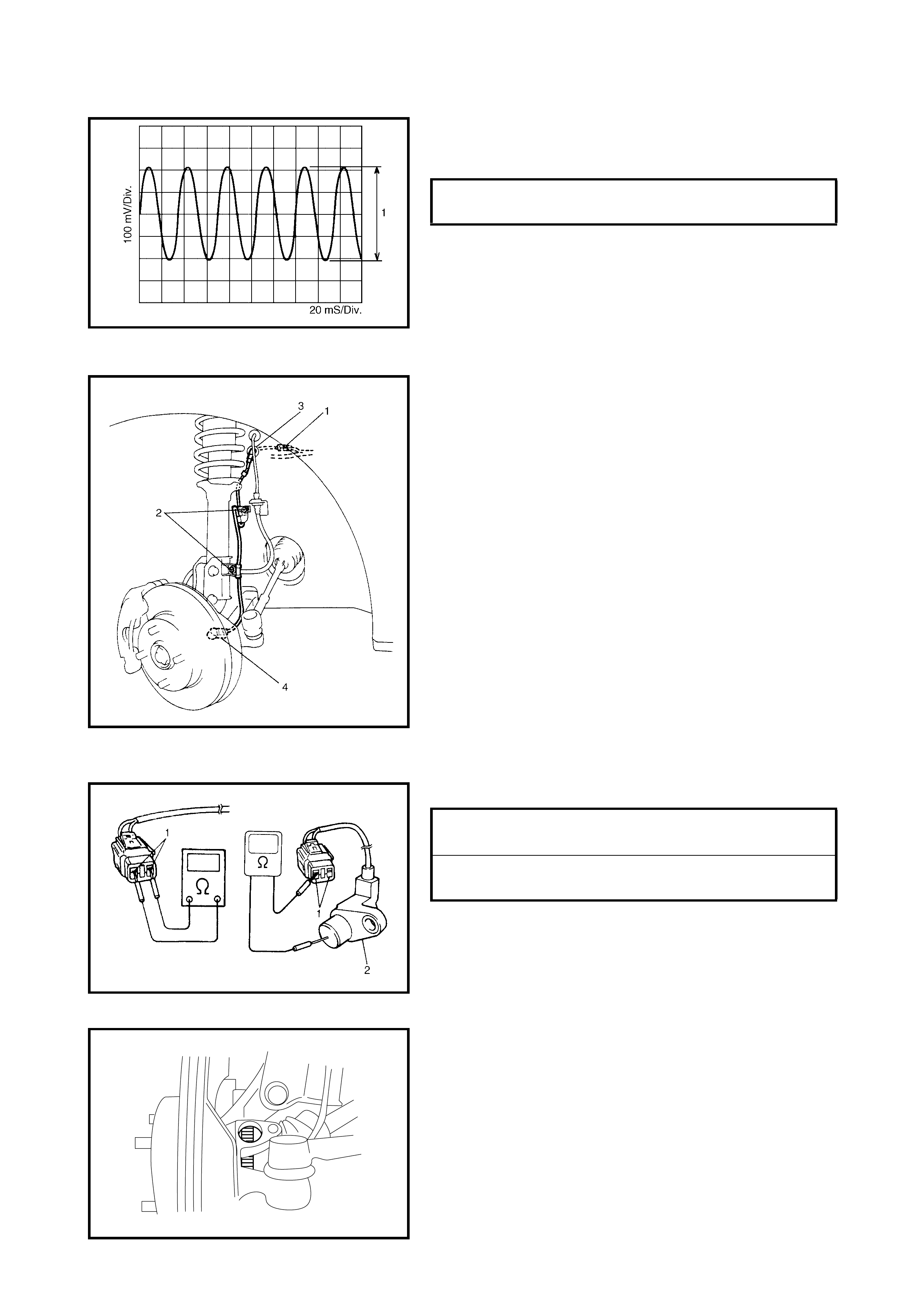
REFERENCE
When using an oscilloscope for this check, check if peak-
to-peak voltage (1) meets specification and waveform is
complete.
REMOVAL
1. Disconnect negative cable at battery.
2. Disconnect the front wheel speed sensor connector
(1).
3. Hoist vehicle and remove wheel.
4. Remove the harness clamp bolts (2) and grommet (3).
5. Remove the front wheel speed sensor (4) from
knuckle.
CAUTION:
• Do not pull wire harness when removing the front
wheel speed sensor.
• Do not cause damage to the surface of the front
wheel speed sensor and do not allow dust, etc. to
enter its installation hole.
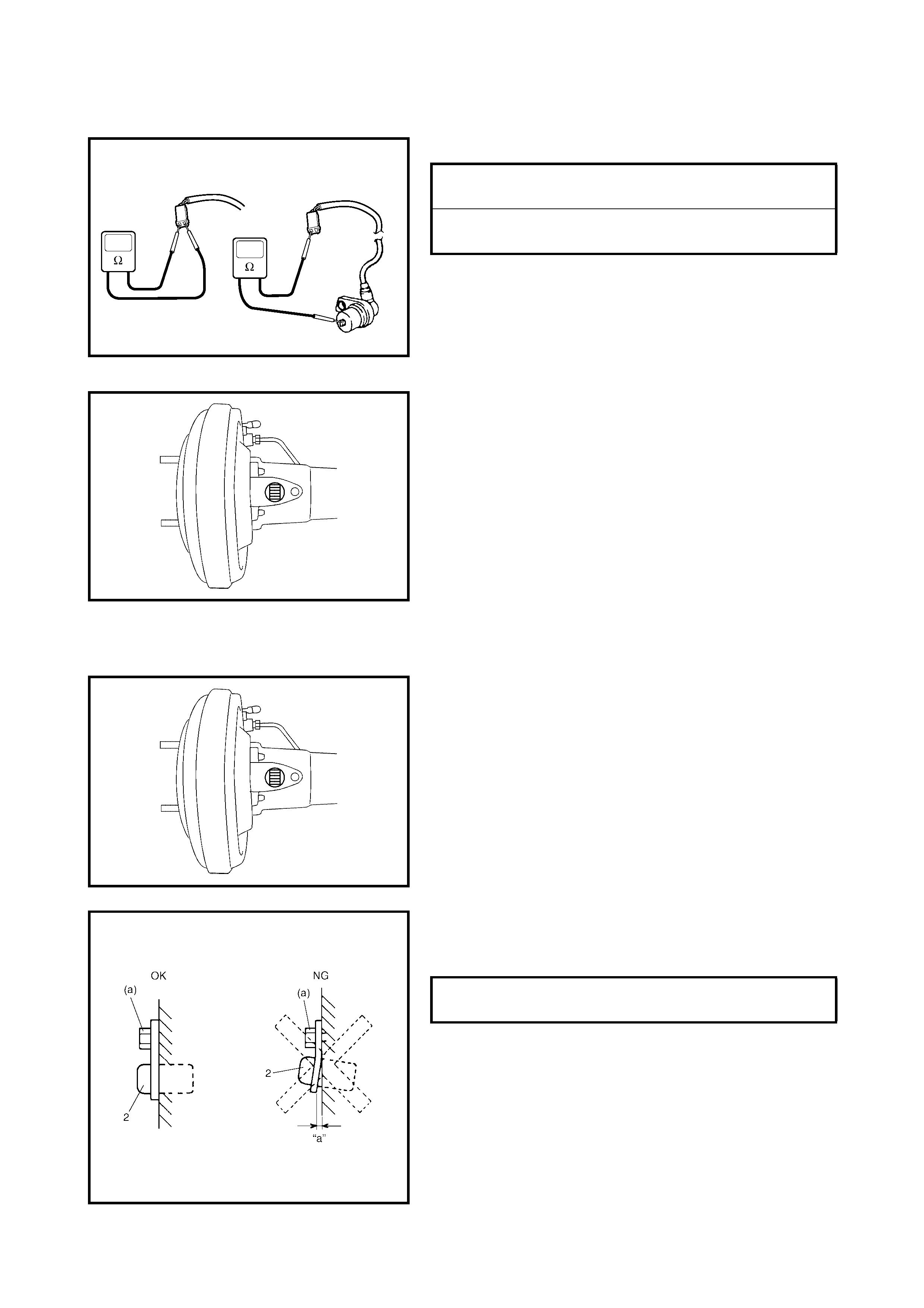
SENSOR INSPECTION
• Check sensor for damage.
• Check sensor for resistance and continuity.
• If the chec k re sult i s not as speci fied a nd any malfun c-
tion is found, replace.
SENSOR RING INSPECTION
• Check ring for missing, damage or deformation.
• Turn drive shaft and check if ring rotation is free from
eccentricity and looseness.
• Check that no foreign material is attached.
If any fault is found, repair or replace. Refer to
3.6 FRONT WHEEL SPEED SENSOR RING in this
Section.
PEAK TO PEAK VOLTAGE AT 1/2 TO 1
ROTATION PER SECOND 150 mV or more
at 20 Hz
RESITANCE BETWEEN BOTH SEN-
SOR TERMINALS (1) 1.2 – 1.6k
Ω
at
20°C
CONTINUITY BETWWEN SENSOR
TERMINAL AND BODY (2) No continuity
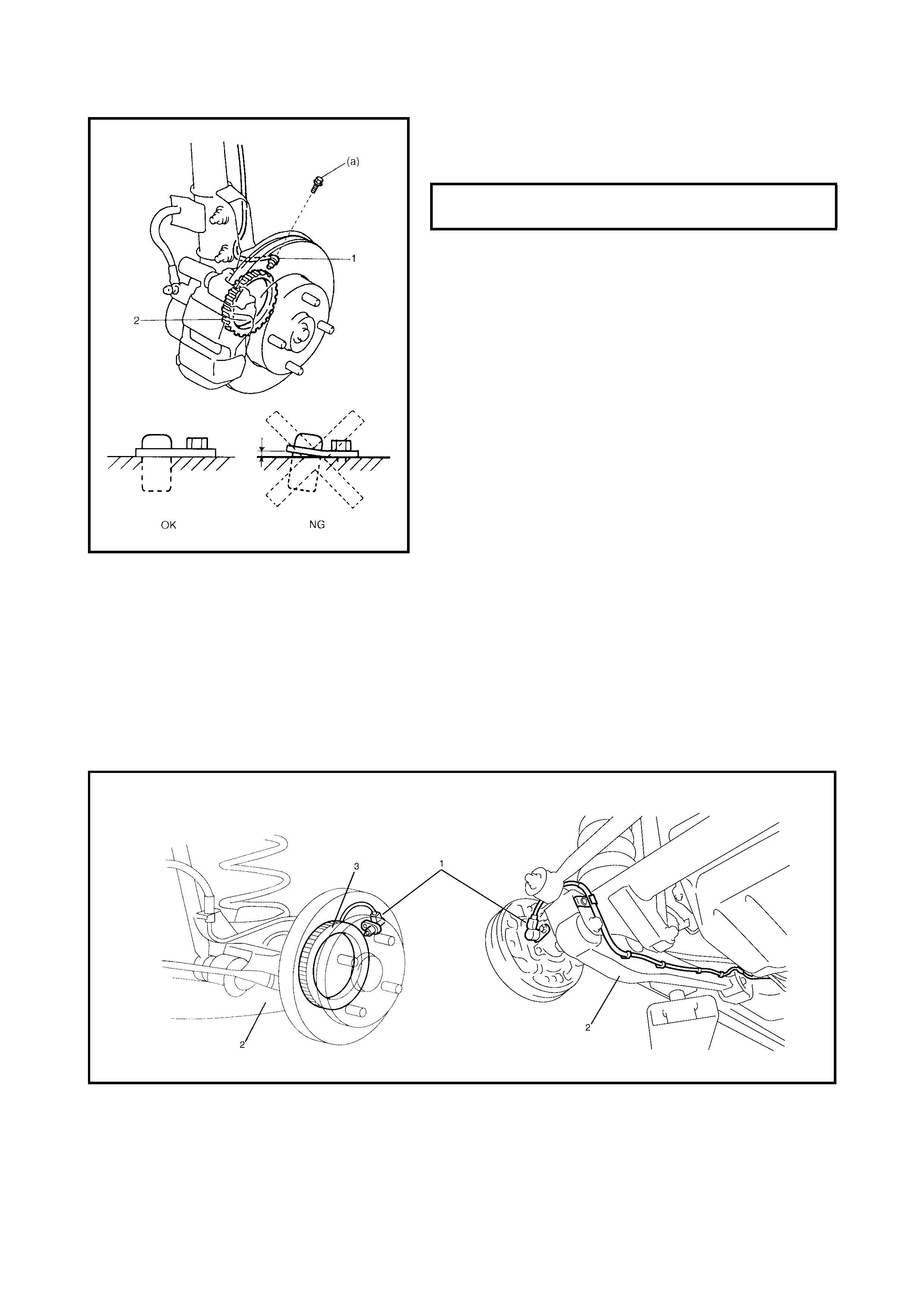
INSTALLATION
1. Check that no foreign material is attached to the
sensor (1) and sensor ring (2).
2. Install it by reversing removal procedure.
CAUTION:
Do not pull or twist wire harness more
than necessary when installing front wheel speed
sensor.
3. Check that there is no clearance between sensor and
knuckle.
3.6 FRONT WHEEL SPEED SENSOR RING
NOTE: The front wheel sensor ring cannot be removed or
replaced al one. If front wheel sensor ring requi res replace-
ment, replace it as a wheel side joint assembly of drive
shaft.
For removal and installation of wheel side joint assembly of
drive shaft, refer to Section 4A FRONT DRIVE SHAFT.
3.7 RE AR WHEEL SPEED SENSOR
Legend
FRONT WHEEL SPEED SENSOR BOLT
(a) TIGHTENING TORQUE 11 Nm
1. Left rear wheel speed sensor 3. Trailing arm
2. Right rear wheel speed sensor 4. Sensor ring
OUTPUT VOLTAGE INSPECTION
1. Turn ignition switch OFF.
2. Remove rear seat, refer to Section 9, 4.2 REAR SEAT.
3. Turn over floor carpet.
4. Hoist vehicle.
5. Disconnect wheel speed sensor connector.
6. Connect a voltmeter between connector (1) terminals.
7. While turning wheel at a speed of approximately 1/2
rotation to 1 rotation per second, check AC voltage of
sensor.
8. If measured voltage is not as specified, check sensor,
ring and their installation conditions.
REFERENCE
When using an oscilloscope for this check, check if peak-
to-peak voltage (1) meets specification and waveform is
complete.
REMOVAL
1. Disconnect negative cable at battery.
2. Remove rear seat, refer to Section 9, 4.2 REAR SEAT.
3. Turn over floor carpet.
4. Hoist vehicle.
5. Disconnect the rear wheel speed sensor connector (1).
NOTE: Do not detach grip of rear wheel speed sensor con-
nector from vehicle body unless replacement is necessary.
6. Detach ABS wheel sensor wire harness (2) from the
trailing arm (3).
7. Remove the rear wheel speed sensor (4) from rear
axle housing.
CAUTION:
• Do not pull wire harness when removi ng rear wh eel
speed sensor.
• Do damage th e sur fa ce of rea r wheel s p eed se n sor
and do not allow dust, etc. to enter its installation
hole.
OUTPUT AC VOLTAGE AT 1/2 TO 1
ROTATION PER SECOND 106 mV or more
PEAK TO PEAK VOLTAGE AT 1/2 TO 1
ROTATION PER SECOND 150 mV or more
at 20 Hz
SENSOR INSPECTION
• Check sensor for damage.
• Check sensor for resistance and continuity.
• If the chec k re sult i s not as speci fied a nd any malfun c-
tion is found, replace.
SENSOR RING INSPECTION
• Check if r in g se rra tio n (t eeth ) a re mis s ing , da mag ed or
deformed.
• Turn wheel and check if ring rotation is free from
eccentricity and looseness.
• Check that no foreign material is attached.
• If any faulty is found, repair or replace.
INSTALLATION
Reverse removal procedure for installation noting the fol-
lowing.
• Check that no foreign material is attached to sensor (1)
and ring.
• Install the wheel speed sensor and its bolt at the cor-
rect position as shown in figure.
Tighten sensor bolt to specified torque.
CAUTION:
Do not pull or twist wire harness more
than necessary when installing rear wheel speed
sensor.
• Check that there is no clearance between sensor and
rear axle shaft.
RESISTANCE BETWEEN BOTH
SENSOR TERMINALS AT 20°C 1.2 – 1.6 k
Ω
RESISTANCE BETWEEN SENSOR
TERMINAL AND BODY No continuity
SENSOR BOLT (a) TIGHTENING
TORQUE 11 Nm
3.8 REAR WHEEL SPEED SENSOR RING
NOTE: The rear whee l sp eed sen so r rin g canno t be r em ove d or repl ac ed alone . If the r ea r wheel spe ed s en-
sor ring requires replacement, replace it as the retainer ring of the rear axle shaft.
REMOVAL / INSTALLATION
For remo val and installati on of the rear axle shaft retainer r ing, refer to Secti on 3E, 3.7 REAR AXLE SHAF T
AND WHEEL BEARING.
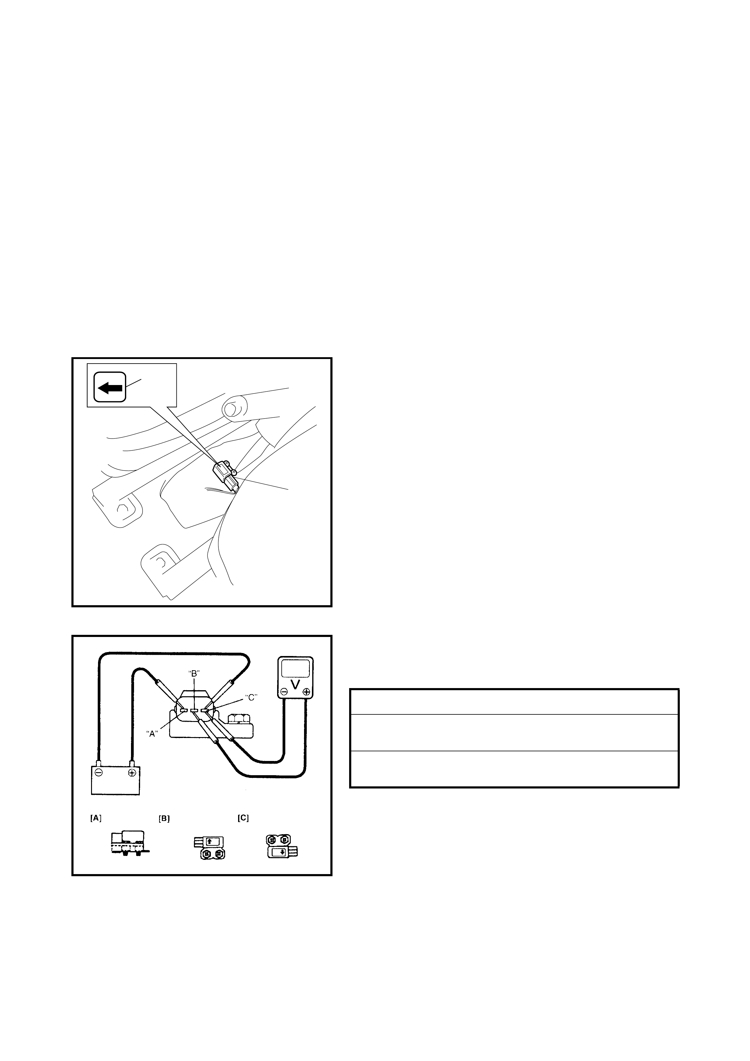
3.9 G-SENSOR
REMOVAL
1. Turn ignition switch OFF and disconnect the battery
negative ca ble.
2. Remove the ABS fuse from fuse box.
3. Disconnect the ABS hydraulic unit/control module
assembly connector by pulling up lock.
4. Remove the centre console box.
5. Remove the G-sensor (1) from the floor noting the
forward direction (2).
6. Disconne ct the conne cto r from sen sor.
CAUTION:
The sensor must not be dropped or
shocked. It will affect its ori ginal per forman ce.
INSPECTION
Connect positive cable of 12 volt battery to A terminal of
sensor and gr oun d c able to C te rm in al. Th en usi ng v oltme-
ter, check voltage between B terminal and C terminal.
If measured voltage is not as specified, replace sensor.
INSTALLATION
1. Connect connector to the sensor securely.
2. Install the sensor onto floor so that the arrow mark
directs vehicle forward.
3. Connect the ABS hydraulic unit/control module
assembly connector.
4. Install the ABS fuse to fuse box.
5. Install the rear console box.
1
2
SENSOR PLACED HORIZONTALLY [A] 2 – 3 V
SENSOR PLACED WITH ARROW UP
[B] 3 – 4 V
SENSOR PLACED WITH ARROW
DOWN [C] 1 – 2 V
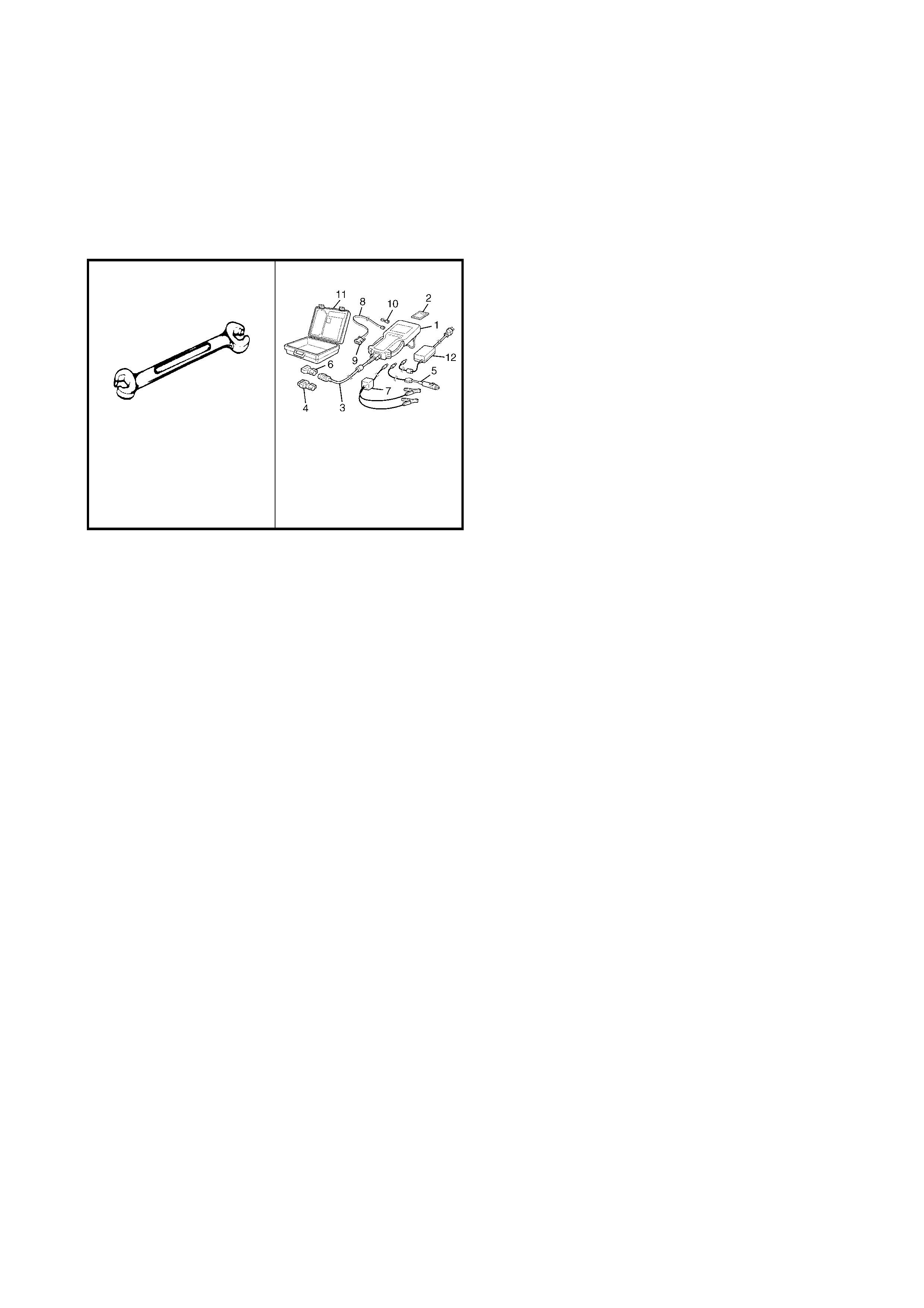
4. SPECIAL TO OLS
NOTE: Refer to Section 0A GENERAL INFORMATION — 7. CONSOLIDATED TOOLS for a detailed list of
special tools and the local equivalent if one is available.
NOTE:
This kit includes the following items:
1. Tech 2, 2. PCMCIA card, 3. DLC cable, SAE 16/19 adapter, 5. Cigarette cable, 6. DLC loopback adapter,
7. Battery power cable, 8. RS232 cable, 9. RS232 adapter, RS232 loopback connector, 11. Storage case,
12. Power supply.
09950-78220
Flare nut wrench (10 mm) Tech 2 kit (Scan Tool)
(See NOTE below.)