
SECTION 5E1 - ANTILOCK BRAKE SYSTEM (ABS) (2004 UPDATE)
WARNING:
For vehicles equipped with a Supplemental Restraint (Air Bag) System:
• Service on and around the air bag system components or wiring must be performed only by an
authorized HOLDEN dealer. Refer to “System Components and Wiring Location View and
Connectors” under “General Description” in Section 10B in order to confirm whether you are
performing service on or near the air bag system components or wiring. Please observe all
WARNINGS and “Service Precautions” under “On-Vehicle Service” in Section 10B before
performing service on or around the air bag system components or wiring. Failure to follow
WARNINGS could result in unintentional activation of the system or could render the system
inoperative. Either of these two conditions may result in severe injury.
• Technical service work must be started at least 90 seconds after the ignition switch is turned to
the “LOCK” position and the negative cable is disconnected from the battery. Otherwise, the
system may be activated by reserve energy in the Sensing and Diagnostic Module (SDM).
NOTE:
• All brake fasteners are important attaching parts in that they could affect the performance of vital
parts and systems, and/or could result in major repair expense. They must be replaced with one of
same part number or with an equivalent part if replacement becomes necessary. Do not use a
replacement part of lesser quality or substitute design. Torque values must be used as specified
during reassembly to assure proper retention of all parts. There is to be no welding as it may
result in extensive damage and weakening of the metal.
• For the items not listed below, refer to the Section 5E.
General Description
System Circuit
Diagnosis
Precaution in Diagnosing Troubles
Table – A ABS Warning Lamp Circuit
Check – Lamp Does No t Come “ON” at
Ignition Switch ON
Table – B ABS Warning Lamp Circuit
Check – Lamp Comes “ON” Steady
Table – C ABS Warning Lamp Circuit
Check – The Lamp Flashes Continuously
While Ignition Switch is ON
Table – D Code (DTC) is Not Outputted
Even With Diagnosis Switch Terminal
Connected to Ground
Table – E EBD Warning Lamp (Brake Warning
Lamp) Check – Lamp Comes “ON” Steady
Diagnostic Trouble Code (DT C) Check
DTC C1015 (DTC 15) – G Sensor Circuit
DTC C1021 (DTC 21), DTC C1022 (DTC 22) –
Right-Front Wheel Speed Sensor
Circuit or Sensor Ring
DTC C1025 (DTC 25), DTC C1026 (DTC 26) –
Left-Front Wheel Speed Sensor
Circuit or Sensor Ring
DTC C1031 (DTC 31), DTC C1032 (DTC 32) –
Right-Rear Wheel Speed Sensor
Circuit or Sensor Ring
DTC C1035 (DTC 35), DTC C1036 (DTC 36) –
Left-Rear Wheel Speed Sensor
Circuit or Sensor Ring
DTC C1041 (DTC 41) – Right-Front
Inlet Solenoid Circuit
DTC C1045 (DTC 45) – L eft-Front Inlet
Solenoid Circuit
DTC C1051 (DTC 51) – Right-Rear Inlet
Solenoid Circuit
DTC C1055 (DTC 55) – Left-Rear Inlet
Solenoid Circuit
DTC C1042 (DTC 42) – Right-Front Outlet
Solenoid Circuit
DTC C1046 (DTC 46) – Left-Front Outlet
Solenoid Circuit
DTC C1052 (DTC 52) – Right-Rear Outlet
Solenoid Circuit
DTC C1056 (DTC 56) – Left-Rear Outlet
Solenoid Circuit
DTC C1057 (DTC 57) – Power Source Circuit
DTC C1061 (DTC 61) – ABS Pump
Motor Circuit
DTC C1063 (DTC 63) – ABS Fail-Safe
Relay Circuit
DTC C1071 (DTC 71) – ABS Control Module
ON-Vehicle Service
ABS Hydraulic Unit / Control Module
Assembly
Tightening Torque Specifications
Special Tool

General Description
The ABS (Antilock Brake System) controls the fluid pressure applied to the Wheel cylinder of each brake from
the master cylinder so that each wheel is not locked even when hard braking is applied.
This ABS has also the following function.
While braking is applied, but before ABS control becomes effective, braking force is distributed between the front
and rear so as to prevent the rear wheels from being locked too early for better stability of the vehicle.
The main component parts of this ABS include the following parts in addition to those of the conventional brake
system.
• Wheel speed sensor which senses revolution speed of each wheel and outputs its signal.
• ABS warning lamp which lights to inform abnormality when system fails to operate properly.
• ABS hydraulic unit / control module assembly is incorporated ABS control module, ABS hydraulic unit (actu-
ator assembly), fail-safe relay (transistor), pump motor relay (transistor) and G sensor.
– ABS control module which sends operation signal to ABS hydraulic unit to control fluid pressure applied to
each wheel cylinder based on signal from each wheel speed sensor so as to prevent wheel from locking.
– ABS hydraulic unit which operates according to signal from ABS control module to control fluid pressure
applied to wheel cylinder of each 4 wheels.
– Fail-safe relay (transistor) which supplies power to solenoid valve in ABS hydraulic unit.
– Pump motor relay (transistor) which supplies power to pump motor in ABS hydraulic unit.
– G sensor which detects body deceleration speed in ABS hydraulic unit.
This ABS is equipped with Electronic Brake force Distribution (EBD) system that controls a fluid pressure of rear
wheels to best condition, which is the same function as that of proportioning valve, by the signal from wheel sen-
sor independently of change of load due to load capacity and so on. And if the EBD system fails to operate prop-
erly, the brake warning lamp lights to inform abnormality.
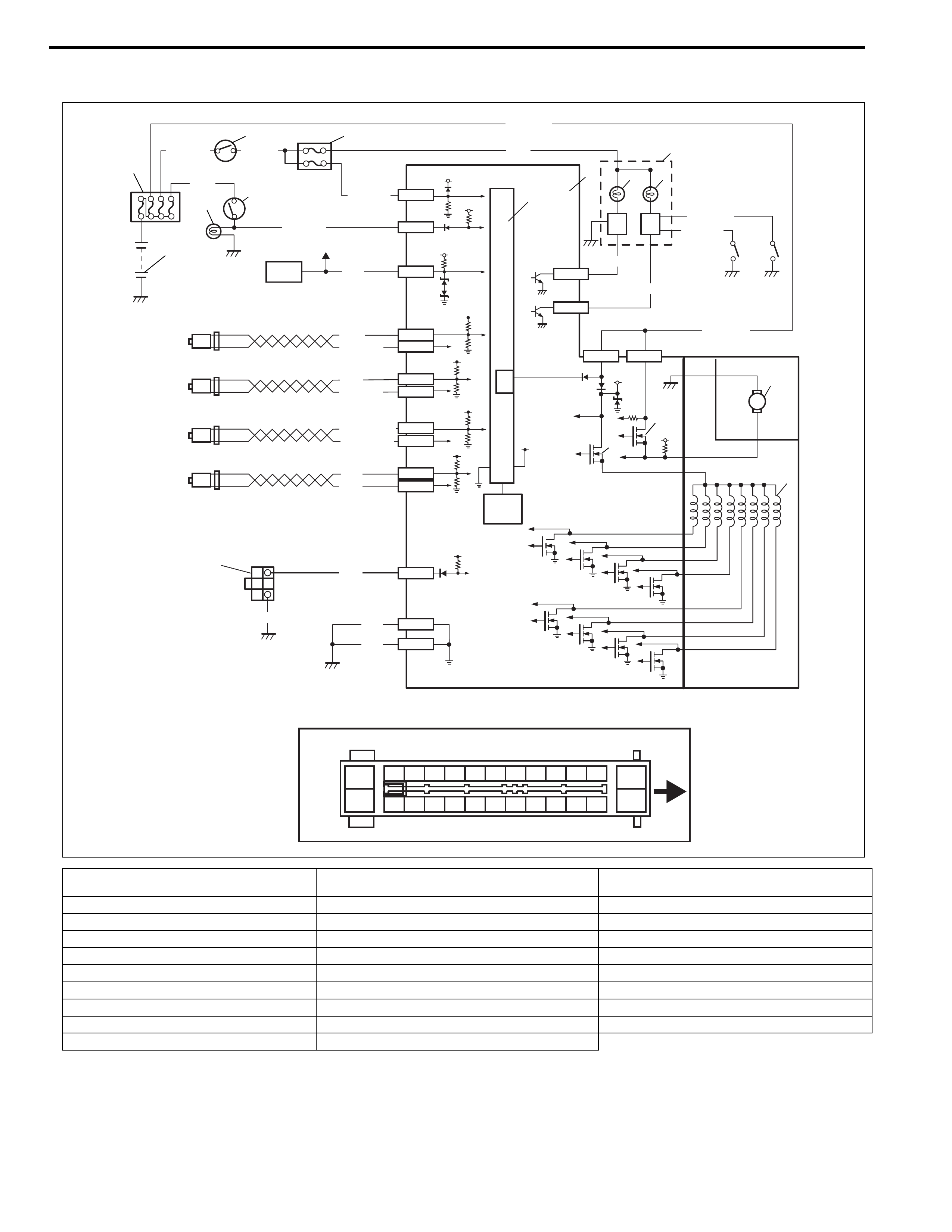
System Circuit
6
WHT/BLU
RED/BLU
PNK/BLU
WHT/BLU
PNK
GRN/WHT
BLK/YEL
BLU
BLK
WHT/BLU
GRN/ORN
BLU
18
20
21
1
2
34
97
5
BLK
E41-7
E41-3
E41-5 E41-17
E41-13
E41-26
E41-20
YEL
BRN
14 E41-25
LT GRN/BLK
LT GRN/RED
15
WHT
WHT/BLK
16
RED
RED/BLK
17
RED/BLK
19 23 24
[A]
1
14
23456789101112
1516171819202122232425
13
26
E41-23
E41
25
22
PNK
BLK
a
E41-24
E41-16
E41-15
E41-18
E41-19
E41-21
E41-22
88RED/BLK
M
12V
10
11
12
13
27
5V
12V
5V
12V
12V
5V
12V
26
VCC
5V
5V
5V
E41-14 E41-1
[A]: Terminal arrangement of ABS hydraulic unit /
control module assembly
9. ABS hydraulic unit / control module assembly 19. To ECM, TCM, SDM and A/C control module (if
equipped)
a: Upside 10. ABS fail-safe relay (transistor) 20. Stop lamp
1. Battery 11. ABS pump motor relay (transistor) 21. Brake light switch
2. Main fuse box 12. Pump motor 22. G sensor (For 4WD model only)
3. Ignition switch 13. Solenoid valves 23. Brake fluid level switch
4. Circuit fuse box 14. Right-rear wheel speed sensor 24. Parking brake switch
5. Combination meter 15. Left-rear wheel speed sensor 25. Monitor connector
6. ABS warning lamp 16. Right-front wheel speed sensor 26. Internal memory
7. EBD warning lamp (Brake warning lamp) 17. Left-front wheel speed sensor 27. Power control unit
8. Lamp driver module 18. Data link connector

TERMINAL CIRCUIT
E41 1 ABS pump motor relay (transistor)
2–
3 Brake light switch
4–
5 Data link connector
6–
7 Ignition switch
8–
9–
10 –
11 –
12 –
13 Ground
14 ABS fail-safe relay (transistor)
15 Left-rear wheel speed sensor (+)
16 Left-rear wheel speed sensor (–)
17 ABS warning lamp
18 Right-front wheel speed sensor (–)
19 Right-front wheel speed sensor (+)
20 Monitor connector
21 Left-front wheel speed sensor (+)
22 Left-front wheel speed sensor (–)
23 EBD warning lamp (Brake warning lamp)
24 Right-rear wheel speed sensor (–)
25 Right-rear wheel speed sensor (+)
26 Ground
Diagnosis
To ensure that the trouble diagnosis is done accurately and
smoothly, observe “Precaution in Diagnosing Troubles” and follow
“ABS Diagnostic Flow Table” in this section.
Precaution in Diagnosing Troubles
• If the vehicles was operated in any of the following ways,
ABS warning lamp may light momentarily but this does not
indicate anything abnormal in ABS.
– The vehicle was driven with parking brake pulled.
– The vehicle was driven with brake dragging.
– The vehicle was stuck in mud, sand, etc.
– Wheel spin occurred while driving.
– Wheel(s) was rotated while the vehicle was jacked up.
• Be sure to read “Precautions for Electrical Circuit Service” in
Section 0A before inspection and observe what is written
there.
• Be sure to use the trouble diagnosis procedure as described
in the flow table. Failure to follow the flow table may result in
incorrect diagnosis. (Some other diagnosis trouble code may
be stored by mistake in the memory of ABS control module
during inspection.)
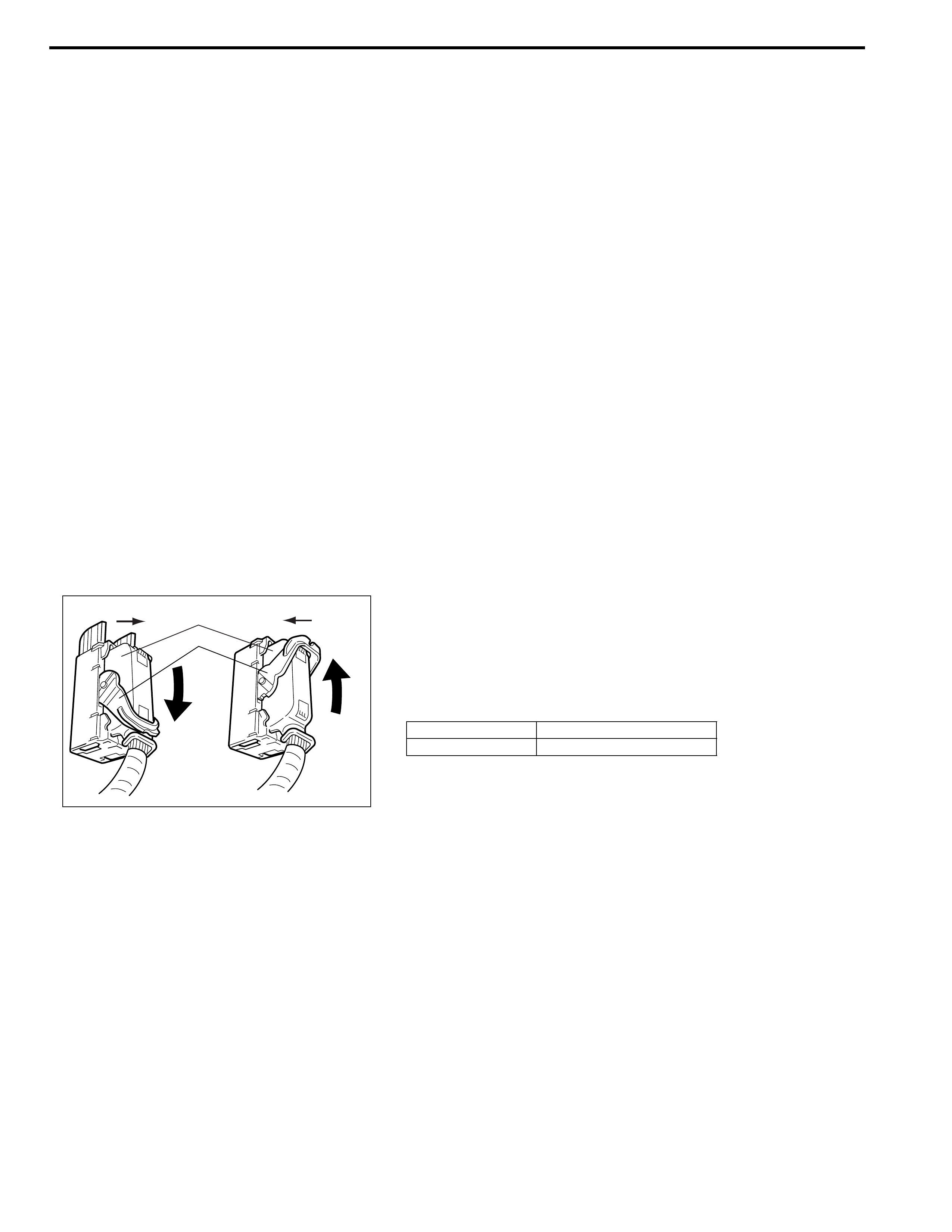
• When disconnecting ABS hydraulic unit / control module
connector (1), pull down lock lever (2) of connector.
When connecting, set the connector on ABS hydraulic unit /
control module assembly and pull up the lock lever (2) unit it
locks.
[A]: Disconnect [C]: Pull down to disconnect
[B]: Connect [D]: Pull up to connect
2
1
CD
[A] [B]
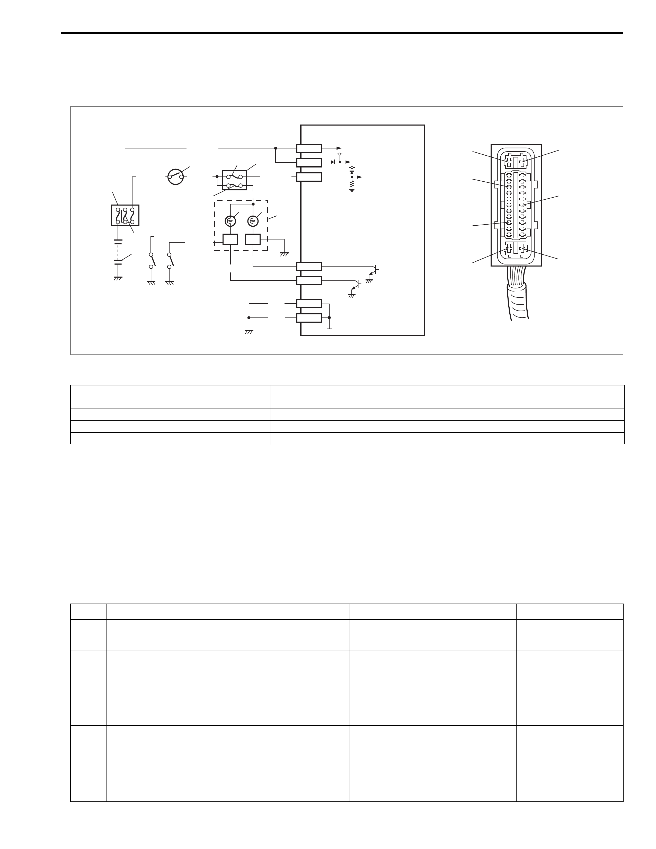
Table – A ABS Warning Lamp Circuit Check – Lamp Does Not Come “ON” at
Ignition Switch ON
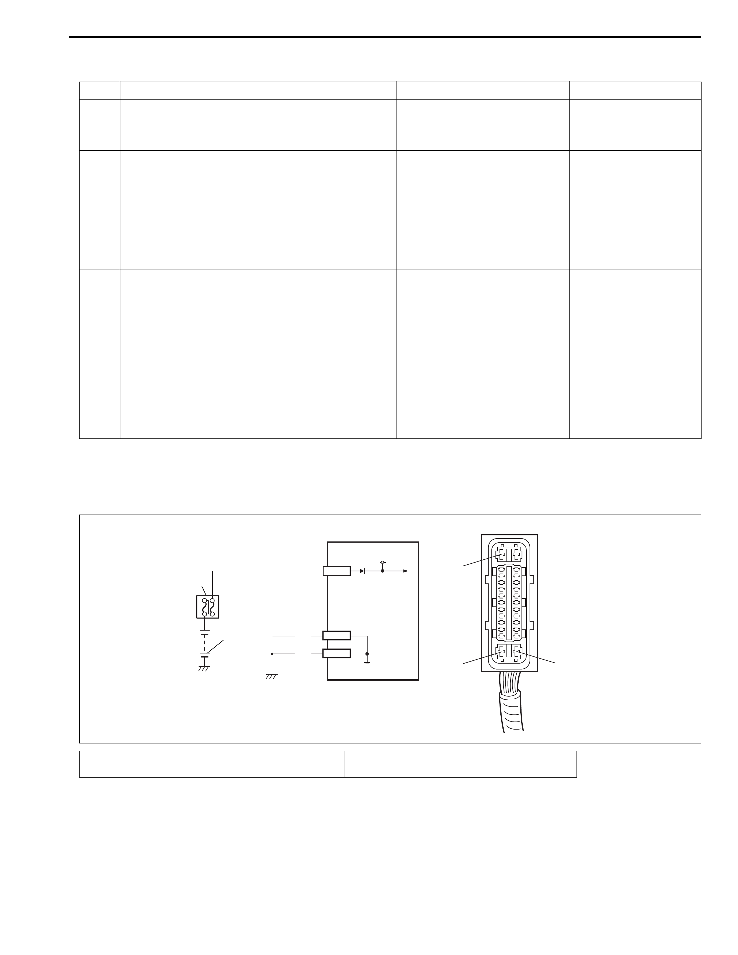
System Circuit Diagram
Circuit Description
Operation (ON/OFF) of ABS warning lamp is controlled by ABS control module through lamp driver module in
combination meter.
If the Antilock brake system is in good condition, ABS control module turns ABS warning lamp ON with ignition
switch turned ON, keeps it ON for 2 seconds and then turns it OFF. If an abnormality in the system is detected,
ABS warning lamp is turned ON continuously by ABS control module. Also, it is turned ON continuously by lamp
driver module when the connector of ABS control module is disconnected.
Inspection
WHT/BLU
WHT/BLU BLK/YEL
RED/BLK
PNK/BLU
RED/BLU
BLU
GRN/ORN
BLK
BLK
313 4
5
88
11
7
2
12
1
910
6
E41-14
E41-1
E41-7
E41-17
E41-23
E41-13
E41-26
RED/BLK
E41-14
E41-17
E41-23
E41-26
E41-1
E41-7
E41-13
[A]
14
12V
12V
[A]: ABS hydraulic unit / control module connector E41 5. Combination meter 10. Parking brake switch
1. Battery 6. EBD warning lamp (Brake warning lamp) 11. ABS hydraulic unit / control module assembly
2. Main fuse box 7. ABS warning lamp 12. “ABS” fuse (50 A)
3. Ignition switch 8. Lamp driver module 13. “ABS” fuse (10A)
4. Circuit fuse box 9. Brake fluid level switch 14. “METER” fuse
Step Action Yes No
1 1) Turn ignition switch to ON position.
Do other warning lamp come ON?
Go to Step 2. Go to Step 4.
2 1) Turn ignition switch to OFF position.
2) Disconnect ABS hydraulic unit / control
module connector.
Does ABS warning lamp light with ignition
switch turned ON?
Substitute a known-good ABS
hydraulic unit / control module
assembly and recheck.
Go to Step 3.
3 1) Remove combination meter with ignition
switch turned OFF.
Is bulb of ABS warning lamp in good condition?
“RED/BLU” circuit shorted to
ground. If OK, replace combina-
tion meter (lamp driver module).
Replace bulb.
4 Is “METER” fuse in good condition? Open in “BLU” wire to combina-
tion meter or poor connection.
Repair and replace.

Table – B ABS Warning Lamp Circuit Check – Lamp Comes “ON” Steady
Refer to “Table – A ABS Warning Lamp Circuit Check – Lamp Does Not Come “ON” at Ignition Switch ON” in
this section for System Circuit Diagram and Circuit Description.
Inspection
Step Action Yes No
1 Perform diagnostic trouble code check.
Is there any DTC(s)?
Go to Step 7 of “ABS
Check:”.
Go to Step 2.
2 Is “ABS” fuses (50 A and 10 A) in good condi-
tion?
Go to Step 3. Replace fuse and check
circuit for short to ground.
3 1) Turn ignition switch to OFF position.
2) Disconnect ABS hydraulic unit / control
module connector.
3) Check for proper connection to ABS hydrau-
lic unit / control module connector at termi-
nals “E41-7”, “E41-17”, “E41-13” and “E41-
26”.
4) If OK then turn ignition switch to ON position
and measure voltage between terminal
“E41-7” and vehicle body ground.
Is it 10 – 14 V?
Go to Step 4. “GRN/ORN” circuit open.
4 1) Turn ignition switch to OFF position.
2) Check for proper connection to ABS hydrau-
lic unit / control module connector at termi-
nals “E41-1” and “E41-14”.
3) If OK then turn ignition switch to ON position
and measure voltage between each termi-
nal of “E41-1”, “E41-14” and vehicle body
ground.
Are they 10 – 14 V?
Go to Step 5. “WHT/BLU” circuit open.
5 1) Turn ignition switch to ON position and light
the ABS warning lamp.
2) Connect terminal “E41-17” of disconnected
connector to vehicle body ground using ser-
vice wire.
Does ABS warning lamp turn off?
Go to Step 6. “RED/BLU” circuit open.
If wire and connection are
OK, replace combination
meter (lamp driver mod-
ule).
6 1) Turn ignition switch to OFF position.
2) Measure resistance between each terminal
of “E41-13”, “E41-26” and vehicle body
ground.
Is resistance less than 2 Ω?
Substitute a known-good
ABS hydraulic unit / con-
trol module assembly and
recheck.
“BLK” wire circuit in open
or high resistance.
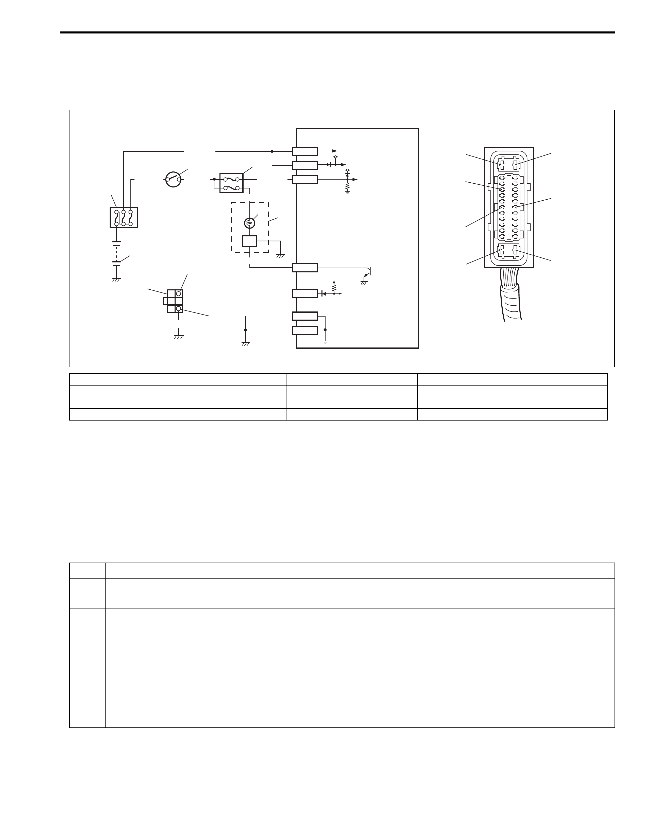
Table – C ABS Warning Lamp Circuit Check – The Lamp Flashes Continuously
While Ignition Switch is ON
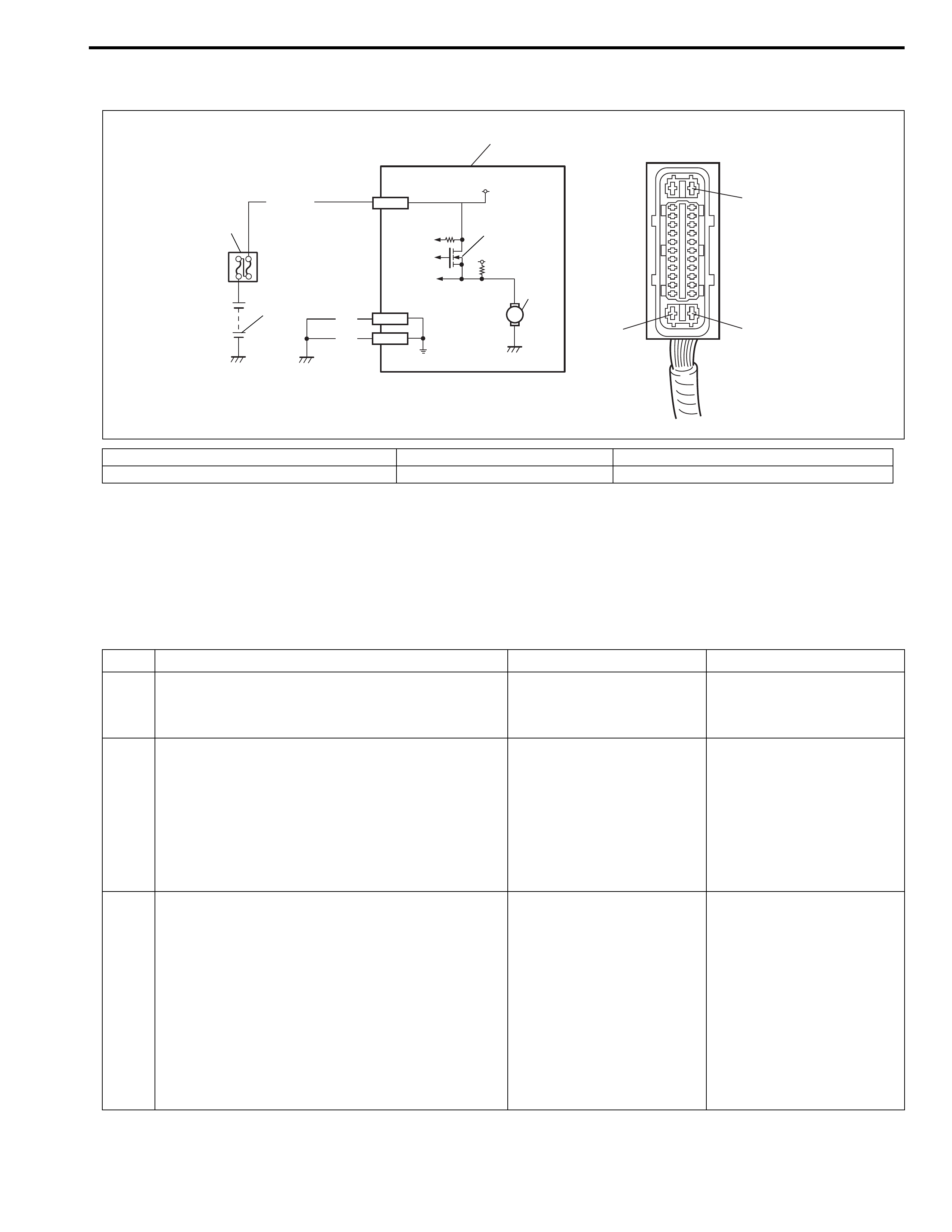
System Circuit Diagram
Circuit Description
When diagnosis switch terminal is shorted or connected to the ground with ignition switch turned ON, diagnosis
trouble code (DTC) is indicated by flashing of ABS warning lamp only in the following cases.
• Normal DTC (12) is indicated if no malfunction DTC is detected in the ABS.
• A history malfunction DTC is indicated by flashing of the lamp if a current malfunction DTC is not detected at
that point although a history malfunction DTC is stored in memory.
Inspection
[A]: ABS hydraulic unit / control module connector E41 4. Circuit fuse box 8. ABS hydraulic unit / control module assembly
1. Battery 5. Combination meter 9. Monitor connector
2. Main fuse box 6. ABS warning lamp 9-1. Diagnosis switch terminal
3. Ignition switch 7. Lamp driver module 9-2. Diagnosis ground terminal
WHT/BLU
WHT/BLU BLK/YEL
RED/BLU
BLU
GRN/ORN
BLK
BLK
34
5
7
8
6
2
1
E41-14
E41-1
E41-7
E41-17
E41-13
E41-26
E41-14
E41-17
E41-20
E41-26
E41-1
E41-7
E41-13
[A]
9
BLK
PNK E41-20
9-2
9-1
12V
12V
5V
Step Action Yes No
1 Is diagnosis switch terminal connected to
ground via service wire?
Go to Step 3. Go to Step 2.
2 1) Turn ignition switch to ON position.
2) Measure voltage between diagnosis switch
terminal and ground.
Is it 10 – 14 V?
Substitute a known-good
ABS hydraulic unit / con-
trol module assembly and
recheck.
“PNK” wire circuit shorted
to ground.
3 1) Turn ignition switch to ON position.
2) Does flashing of ABS warning lamp indicate
DTC?
Go to Step 7 of “ABS
Diagnostic Flow Table” in
this section.
Substitute a known-good
ABS hydraulic unit / con-
trol module assembly and
recheck.
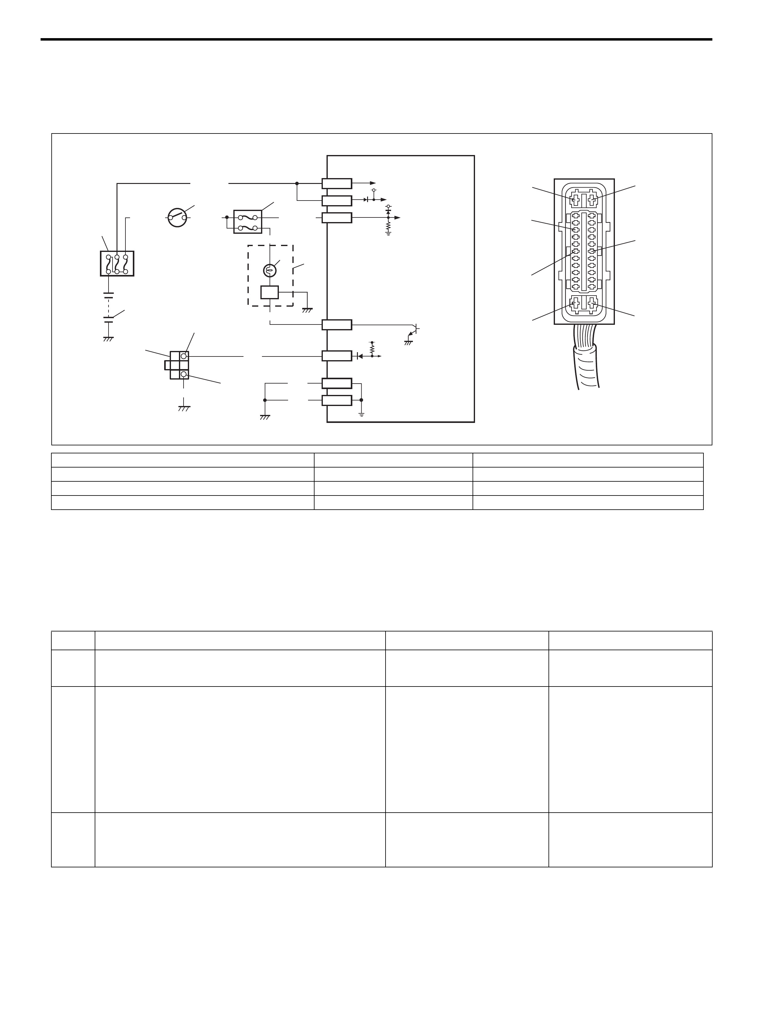
Table – D Code (DTC) is Not Outputted Even With Diagnosis Switch Terminal
Connected to Ground
System Circuit Diagram
Circuit Description
When diagnosis switch terminal is connected to ground with ignition switch turned ON, the ABS control module
outputs diagnostic trouble code by flashing ABS warning lamp.
Inspection
[A]: ABS hydraulic unit / control module connector E41 4. Circuit fuse box 8. ABS hydraulic unit / control module assembly
1. Battery 5. Combination meter 9. Monitor connector
2. Main fuse box 6. ABS warning lamp 9-1. Diagnosis switch terminal
3. Ignition switch 7. Lamp driver module 9-2. Diagnosis ground terminal
WHT/BLU
WHT/BLU BLK/YEL
RED/BLU
BLU
GRN/ORN
BLK
BLK
34
5
7
8
6
2
1
E41-14
E41-1
E41-7
E41-17
E41-13
E41-26
E41-14
E41-17
E41-20
E41-26
E41-1
E41-7
E41-13
[A]
9
BLK
PNK E41-20
9-2
9-1
12V
12V
5V
Step Action Yes No
1 Is it shorted diagnosis switch terminal and
ground terminal by service wire properly?
Go to Step 2. Connect service wire
securely.
2 1) Disconnect service wire.
2) Disconnect ABS hydraulic unit / control
module connector.
3) Measure resistance between diagnosis
switch terminal and connector terminal
“E41-20”.
Is it infinite (∞)?
“PNK” circuit open. Go to Step 3.
3 1) Measure resistance between ground termi-
nal of monitor coupler and body ground.
Is continuity indicated?
Go to Step 4. “BLK” circuit open or poor
connection.

Table – E EBD Warning Lamp (Brake Warning Lamp) Check – Lamp Comes
“ON” Steady
Circuit Description
EBD warning lamp (brake warning lamp) is controlled by parking brake switch, brake fluid level switch and ABS
control module / hydraulic unit assembly through lamp driver module in combination meter. Refer to “Table – A
ABS Warning Lamp Circuit Check – Lamp Does Not Come “ON” at Ignition Switch ON” in this section for circuit
diagram.
Inspection
4 1) Check for proper connection to ABS hydrau-
lic unit / control module at terminal “E41-
20”.
2) If OK, then check ABS warning lamp circuit
referring to “Table – A ABS Warning Lamp
Circuit Check – Lamp Does Not Come “ON”
at Ignition Switch ON”, “Table – B ABS
Warning Lamp Circuit Check – Lamp
Comes “ON” Steady” and “Table – C ABS
Warning Lamp Circuit Check – The Lamp
Flashes Continuously While Ignition Switch
is ON” in this section.
Is it in good condition?
Substitute a known-good
ABS hydraulic with / con-
trol module assembly and
recheck.
Repair “ABS” warning
lamp circuit.
Step Action Yes No
Step Action Yes No
1 1) Make sure that :
• Parking brake is completely released.
• Brake fluid level is upper than the minimum
level.
Are the check results OK?
Go to Step 2. Release parking brake
completely and/or replen-
ish brake fluid.
2 1) Turn ignition switch to ON position.
Does “ABS” warning lamp come on?
Perform “Table – B ABS
Warning Lamp Circuit
Check – Lamp Comes
“ON” Steady” in this sec-
tion.
Go to Step 3.

Diagnostic Trouble Code (DTC) Check
Using ABS Warning Lamp
1) Perform “ABS Warning Lamp Check” in this section.
2) Using service wire (4), connect diagnosis switch terminal (2)
of monitor coupler (1) to ground (3).
3) Turn ignition switch to ON position.
4) Read flashing of ABS warning lamp which represents DTC
as shown in example below and write it down. When more
than 2 DTCs are stored in memory, flashing for each DTC is
repeated three times starting with the smallest DTC number
in increasing order.
For details of DTC, refer to “Diagnostic Trouble Code (DTC)
Table” in this section.
Example : When right-front wheel speed sensor circuit opens (DTC 21)
3 1) Disconnect ABS hydraulic unit / control
module connector with ignition switch
turned off.
2) Check for proper connection to ABS
hydraulic unit / control module connector at
terminals “E41-23”.
3) If OK, apply chocks to wheels and select
gear in neutral position (P range for A/T).
4) Keep brake pedal depressed and start
engine.
Release parking brake.
5) Connect terminal “E41-23” of disconnected
connector to ground using service wire.
Does EBD warning lamp (brake warning lamp)
turn off?
Substitute a known-good
ABS hydraulic unit / con-
trol module assembly and
recheck.
“PNK/BLU” circuit open.
If wire and connection are
OK, replace combination
meter.
Step Action Yes No
5) After completing the check, turn ignition switch off, discon-
nect service wire from monitor coupler.
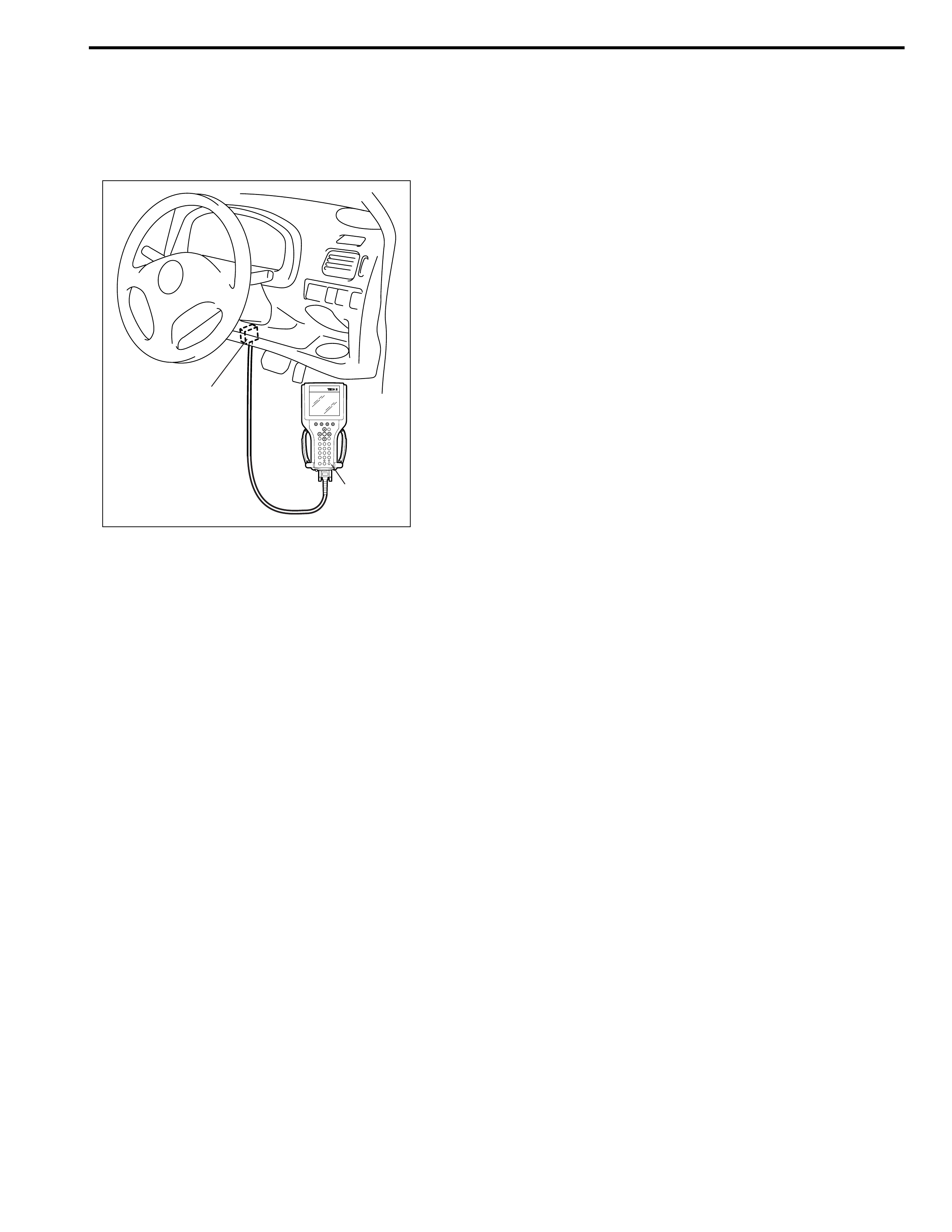
Using TECH 2 Scan Tool
1) Turn ignition switch to OFF position.
2) Connect TECH 2 scan tool to data link connector (1).
Special tool
(A): TECH 2 scan tool
3) Turn ignition switch to ON position.
4) Read DTC according to instructions displayed on TECH 2
scan tool and print it or write it down. Refer to TECH 2 scan
tool operator’s manual for further details.
5) After completing the check, turn ignition switch to OFF posi-
tion and disconnect TECH 2 scan tool from DLC.
If communication between TECH 2 scan tool and ABS
hydraulic unit / control module is not possible, check if
TECH 2 scan tool is communicable by connecting it to ABS
case, TECH 2 scan tool is in good condition. Then check
data link connector and serial data line (circuit) in the vehicle
with which communication was not possible.
DTC C1015 (DTC 15) – G Sensor Circuit
Description
If the signal voltage of G sensor while at a stop does not vary from that while running, this DTC is set.
Therefore, this DTC may be set when a vehicle is lifted up and its wheel(s) is turned. In such case, clear the
DTC and check again.
Inspection
1) Turn ignition switch to OFF position.
2) Check for proper installation of ABS hydraulic unit / control module assembly.
3) If OK, substitute an ABS hydraulic unit / control module assembly with correct part number.
4) Recheck system.
(A)
1
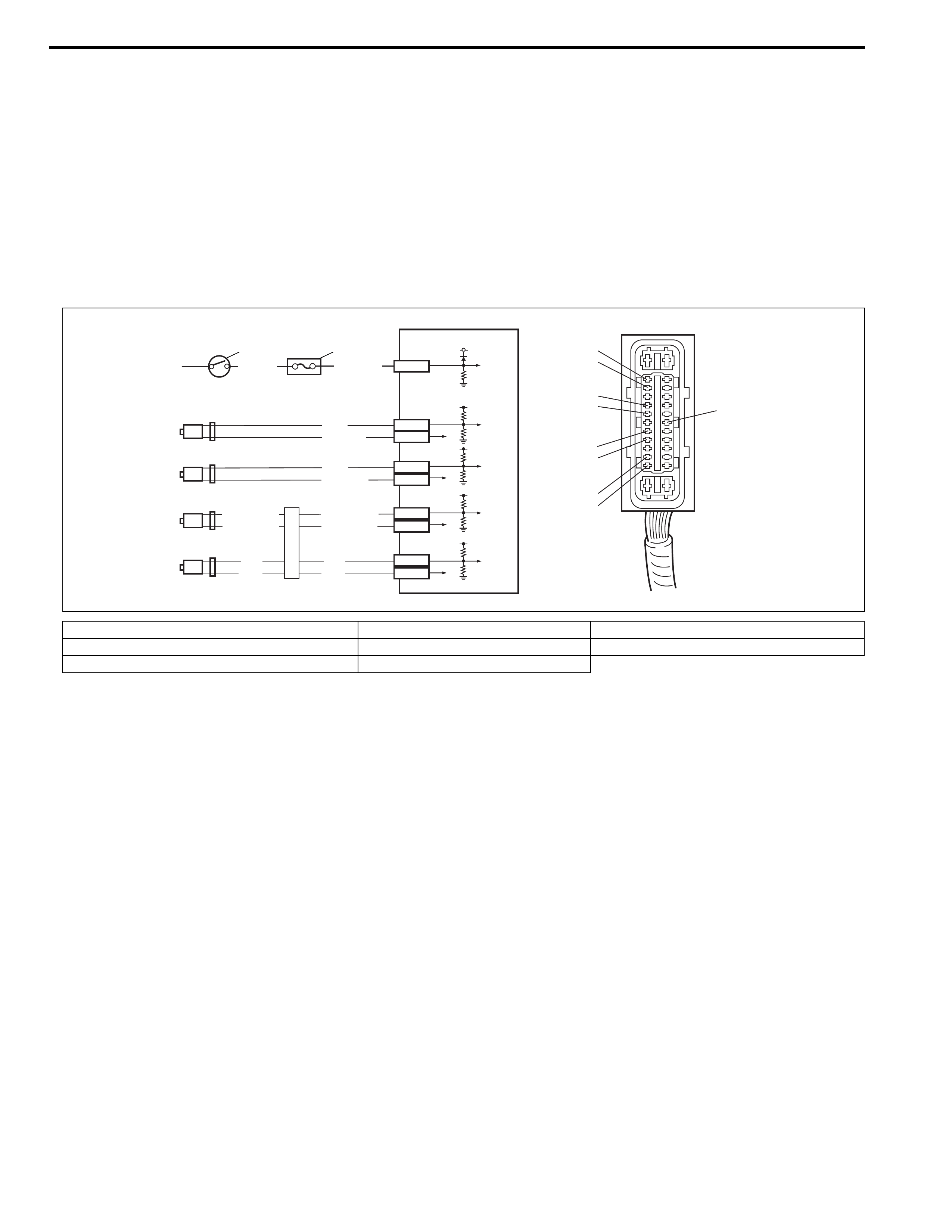
DTC C1021 (DTC 21), DTC C1022 (DTC 22) – Right-Front Wheel Speed Sensor
Circuit or Sensor Ring
DTC C1025 (DTC 25), DTC C1026 (DTC 26) – Left-Front Wheel Speed Sensor
Circuit or Sensor Ring
DTC C1031 (DTC 31), DTC C1032 (DTC 32) – Right-Rear Wheel Speed Sensor
Circuit or Sensor Ring
DTC C1035 (DTC 35), DTC C1036 (DTC 36) – Left-Rear Wheel Speed Sensor
Circuit or Sensor Ring
Description
The ABS control module monitors the voltage at the terminal of each sensor while the ignition switch is ON.
When the voltage is not within the specified range, an applicable DTC will be set. Also, when no sensor signal is
inputted at starting or while running, an applicable DTC will be set.
[A]: ABS hydraulic unit / control module connector E41 3. Right-rear wheel speed sensor 6. Left-front wheel speed sensor
1. Ignition switch 4. Left-rear wheel speed sensor 7. ABS hydraulic unit / control module assembly
2. Circuit fuse box 5. Right-front wheel speed sensor
BLK/YEL GRN/ORN
127
E41-7
YEL
BRN
YEL
BRN
3E41-24
E41-25
LT GRN/BLK
LT GRN/RED
LT GRN/BLK
LT GRN/RED
4E41-16
E41-15
WHT
WHT/BLK
5E41-18
E41-19
RED
RED/BLK
6
E41-15
E41-18
E41-21
E41-24
E41-19 E41-7
E41-22
[A]
E41-21
E41-22
E41-16
E41-25
12V
5V
5V
5V
5V
NOTE:
When the vehicle was operated in any of the following ways, one of these DTCs may be set even when
the sensor is in good condition. If such possibility is suspected, repair the trouble (dragging of brake,
etc.) of the vehicle, clear DTC once and then after performing the driving test as described in Step 2 of
“ABS Diagnosis Flow Table”, check whether or not any abnormality exists.
• The vehicle was driven with parking brake pulled.
• The vehicle was driven with brake dragging.
• Wheel spin occurred while driving.
• Wheel(s) was turned while the vehicle was jacked up.
• The vehicle was stuck.

Inspection
Step Action Yes No
1 Was “ABS Diagnostic Check Flow Table” performed? Go to Step 2. Go to “ABS Diag-
nostic Check Flow
Table” in this sec-
tion.
2 1) Disconnect applicable ABS wheel speed sensor coupler
with ignition switch turned OFF.
2) Measure resistance between terminals of ABS wheel
speed sensor. Refer to “Front Wheel Speed Sensor”
and/or “Rear Wheel Speed Sensor” in this section.
Is measured resistance value as specified?
Go to Step 3. Replace ABS wheel
speed sensor
assembly.
3 1) Turn ignition switch to OFF position.
2) Connect ABS wheel speed sensor coupler.
3) Disconnect ABS hydraulic unit / control module connec-
tor.
4) Check for proper connection to ABS control module at
each sensor terminal.
5) If OK, then turn ignition switch to ON position and mea-
sure voltage between sensor terminal of module con-
nector and body ground.
Is it 0V?
Go to Step 4. ABS wheel speed
sensor circuit
shorted to power.
4 1) Turn ignition switch to OFF position.
2) Measure resistance between the following points.
• Both ABS hydraulic unit / control module connector ter-
minals of the corresponding sensor.
This check result should be the same as above Step 2.
• Either terminal of wheel speed sensor coupler and body
ground.
This check result should be no continuity.
Are both check results OK?
Go to Step 5. Circuit open or
shorted to ground.
5 1) Remove applicable ABS wheel speed sensor.
2) Check sensor for damage or foreign material attached.
Is it in good condition?
Go to Step 4. Clean, repair or
replace.
6 Check front and/or rear sensor ring for the following
(remove rear axle shaft as necessary):
• Rotor serration (teeth) neither missing nor damaged.
• No foreign material being attached.
• Rotor not being eccentric.
• Wheel bearing free from excessive play.
Are they in good condition?
Go to Step 7. Clean, repair or
replace.
7 1) Install ABS wheel speed sensor to knuckle.
2) Tighten sensor bolt to specified torque and check that
there is no clearance between sensor and knuckle.
Is it OK?
Go to Step 8. Replace ABS wheel
speed sensor.
8 Referring to “Reference” of “Front Wheel Speed Sensor”
and/or “Reference” of “Rear Wheel Speed Sensor” in this
section, check output voltage or waveform.
Is specified voltage and/or waveform obtained?
Substitute a known-
good ABS hydrau-
lic unit / control
module assembly
and recheck.
Replace sensor and
recheck.
DTC C1041 (DTC 41) – Right-Front Inlet Solenoid Circuit
DTC C1045 (DTC 45) – Left-Front Inlet Solenoid Circuit
DTC C1051 (DTC 51) – Right-Rear Inlet Solenoid Circuit
DTC C1055 (DTC 55) – Left-Rear Inlet Solenoid Circuit
DTC C1042 (DTC 42) – Right-Front Outlet Solenoid Circuit
DTC C1046 (DTC 46) – Left-Front Outlet Solenoid Circuit
DTC C1052 (DTC 52) – Right-Rear Outlet Solenoid Circuit
DTC C1056 (DTC 56) – Left-Rear Outlet Solenoid Circuit
Description
The ABS control module monitors the output from the valve.
When the output of each valve exceeds the specified value compared with the signal sent from ABS control
module, this DTC is set.
[A]: ABS hydraulic unit / control module assembly connector E41 2. Main fuse box 4. Solenoid valves
1. Battery 3. ABS power control module 5. ABS hydraulic unit / control module assembly
1
2WHT/BLU
BLK
BLK
E41-14
E41-13
[A]
E41-26
12V
E41-26
E41-13
E41-14
3
4
5
5V
Inspection
DTC C1057 (DTC 57) – Power Source Circuit
Description
The ABS control module monitors the power source voltage at terminal “E41-14”. When the power source volt-
age becomes extremely high or low while vehicle is running at more than 20 km/h (13 MPH), this DTC will be
set. As soon as the power source voltage becomes normal, the ABS warning lamp will be turned off and the
ABS control module will return to normal operation, but the set DTC will be remain.
Step Action Yes No
1 Was “ABS Diagnostic Check Flow Table” per-
formed?
Go to Step 2. Go “ABS Diagnostic
Check Flow Table” in
this section.
2 1) Check solenoid operation referring to item
“ABS Hydraulic Unit Operation Check” in
this section.
Is it in good condition?
Check terminal “E41-14”,
E41-13” and “E41-26” con-
nection. If connections are
OK, substitute a known-good
ABS hydraulic unit / control
module assembly and
recheck.
Go to Step 2.
3 1) Turn ignition switch to OFF position.
2) Disconnect ABS hydraulic unit / control mod-
ule connector.
3) Check for proper connection to ABS hydrau-
lic unit / control module connector at termi-
nal “E41-14”.
4) If OK, then measure voltage between termi-
nal “E41-14” of module connector and “E41-
13”.
Is it 10 – 14 V?
Substitute a known-good
ABS hydraulic unit / control
module assembly and
recheck.
“WHT/BLU” or “BLK”
circuit open.
[A]: ABS hydraulic unit / control module connector E41 2. Main fuse box
1. Battery 3. ABS hydraulic unit / control module assembly
BLK
BLK E41-13
WHT/BLU
1
2
3
E41-13
[A]
E41-26
E41-26
E41-14
12V
E41-14

Inspection
Step Action Yes No
1 Was “ABS Diagnostic Check Flow Table” per-
formed?
Go to Step 2. Go to “ABS Diagnostic
Check Flow Table” in this
section.
2 1) Disconnect ABS hydraulic unit / control
module connector with ignition switch
turned OFF.
2) Check for proper connection to ABS hydrau-
lic unit / control module connector at termi-
nals “E41-14”, “E41-13” and “E41-26”.
3) If OK, then turn ignition switch to ON posi-
tion and measure voltage between termi-
nals “E41-14” and “E41-26”.
Is voltage 9 V or more?
Go to Step 5. Go to Step 3.
3 1) Turn ignition switch to OFF position.
2) Check for proper connection to ABS hydrau-
lic unit / control module connector at termi-
nals “E41-13” and “E41-26”.
3) If OK then turn ignition switch to ON position
and measure resistance between each ter-
minal of “E41-13” and “E41-26” and vehicle
body ground
Is resistance less than 2 Ω?
Go to Step 4. “BLK” wire circuit in open
or high resistance.
4 1) Measure voltage between positive battery
terminal and vehicle body ground with
engine running.
Is voltage 9 V or more?
Imperfect short between
“WHT/BLU” wire circuit
and body ground.
Check charging system
referring to “Generator” in
Section 6H.
5 1) Measure voltage between terminals “E41-
14” and “E41-26” with engine running.
Is voltage 18V or less?
Poor connection of “E41-
14” and/or “E41-26” termi-
nals. If the terminals are
in good condition, substi-
tute a known-good ABS
hydraulic unit / control
module and recheck.
Check charging system
referring to “Generator” in
Section 6H.
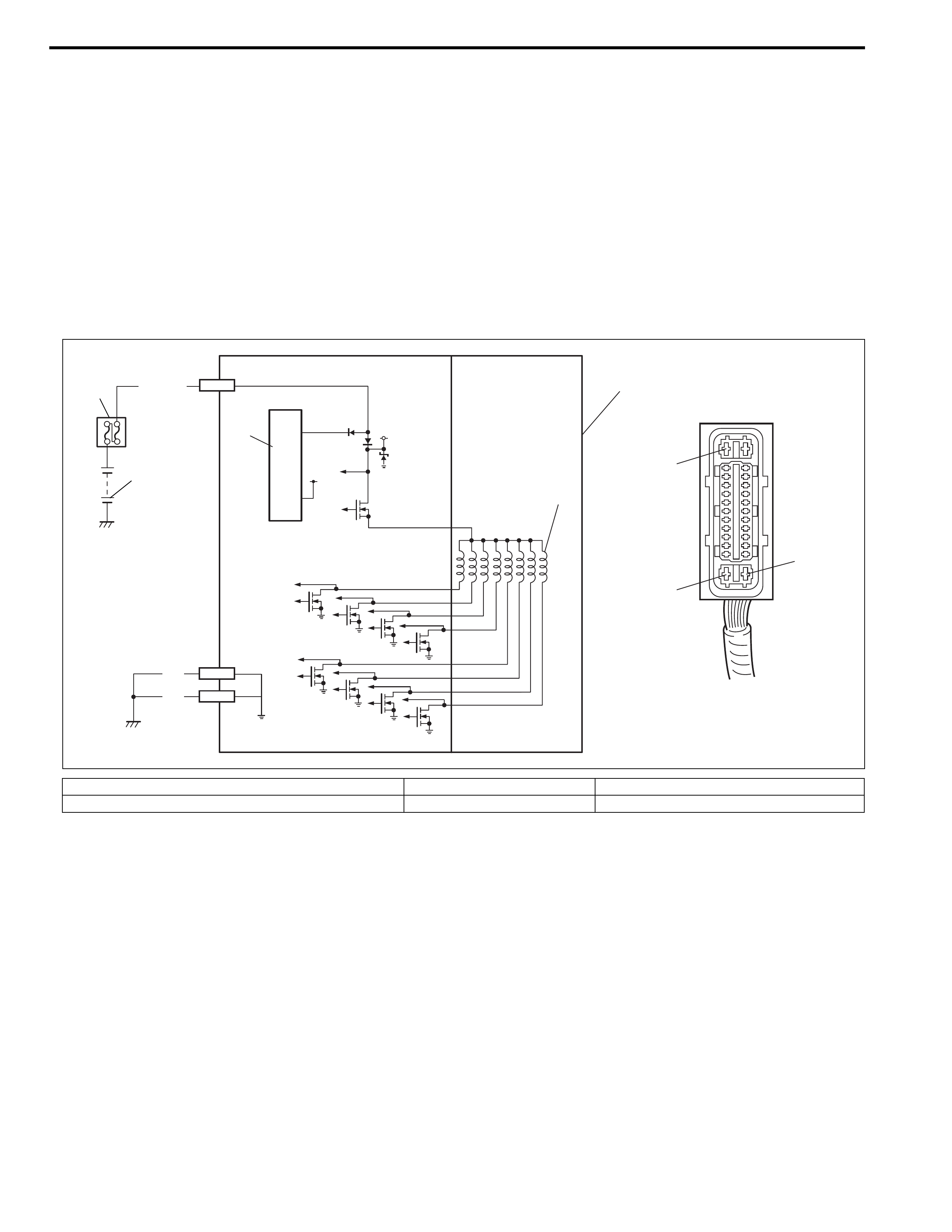
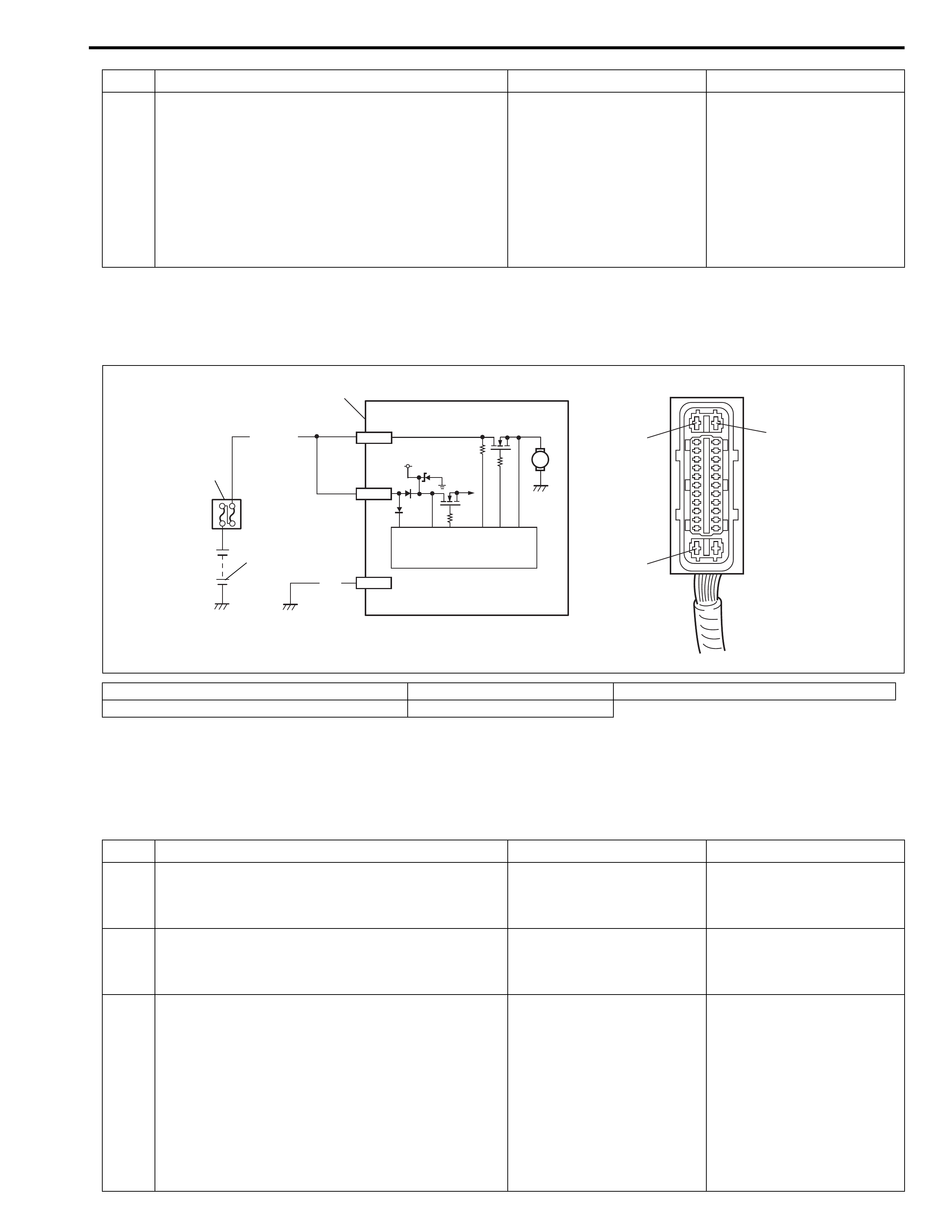
DTC C1061 (DTC 61) – ABS Pump Motor Circuit
Description
The ABS control module monitors the voltage at monitor terminal of pump motor circuit constantly with the igni-
tion switch turned ON. It sets this DTC when the voltage at the monitor terminal does not become high/low
according to ON/OFF commands to the motor relay of the module (does not follow these commands).
Inspection
[A]: ABS hydraulic unit / control module connector E41 2. Main fuse box 4. Pump motor
1. Battery 3. ABS pump motor relay (transistor) 5. ABS hydraulic unit / control module assembly
4
5
1
2
BLK
BLK
E41-1
E41-13
[A]
E41-26
WHT/BLU E41-1
E41-13
E41-26
3
12V
M
12V
Step Action Yes No
1 Was “ABS Diagnostic Check Flow Table” per-
formed?
Go to Step 2. Go to “ABS Diagnostic
Check Flow Table” in this
section.
2 1) Check pump motor referring to “ABS
Hydraulic Unit Operation Check” in this sec-
tion.
Is it in good condition?
Check terminals “E41-1”,
“E41-13” and “E41-26”
connection. If connections
OK, substitute a known-
good ABS hydraulic unit /
control module assembly
and recheck.
Go to Step 3.
3 1) Turn ignition switch to OFF position.
2) Disconnect ABS hydraulic unit / control
module connector.
3) Check for proper connection to ABS
hydraulic unit / control module connector at
terminal “E41-1”.
4) If OK, then measure voltage between termi-
nal “E41-1” of module connector and body
ground.
Is it 10 – 14 V?
Go to Step 4. “WHT/BLU” circuit open.

DTC C1063 (DTC 63) – ABS Fail-Safe Relay Circuit
Description
ABS control module monitors the voltage at the terminal of solenoid circuit constantly with ignition switch turned
ON. Also, immediately after ignition switch is turned ON, perform initial check as follows.
Switch fail-safe relay in the order of OFF → ON and check if voltage changes to Low → High. If anything faulty is
found in the initial check and when the voltage is low with ignition switch turned ON, this DTC will be set.
Inspection
4 Measure resistance between terminal “E41-13”
of ABS hydraulic unit / control module connec-
tor and body ground.
Is it infinite (∞)?
“BLK” circuit open. Substitute a known-good
ABS hydraulic unit / con-
trol module assembly and
recheck.
Step Action Yes No
[A]: ABS hydraulic unit / control module connector E41 3. Ignition switch 6. ABS hydraulic unit / control module assembly
1. Battery 4. Circuit fuse box 7. To solenoid valves
2. Main fuse box 5. Fail safe relay (transistor) 8. “ABS” fuse (50 A)
1
2
6
E41-14
WHT/BLU E41-7
E41-14
E41-7
[A]
8
12V
12V
7
5
5V
VCC
4
GRN/ORN
WHT/BLU BLK/YEL
3
Step Action Yes No
1 Was “ABS Diagnostic Check Flow Table” per-
formed?
Go to Step 2. Go to “ABS Diagnostic
Check Flow Table” in this
section.
2 Check battery voltage. Is it about 11 V or
higher?
Go to Step 3. Check charging system
referring to “Generator” in
Section 6H.
3 Check “ABS” fuse (50 A) and connection.
Is it in good condition?
Go to Step 4. Repair and/or replace
fuse.
DTC C1071 (DTC 71) – ABS Control Module
Description
This DTC will be set when an internal malfunction is detected in the ABS control module.
Inspection
4 1) Turn ignition switch to OFF position.
2) Disconnect ABS hydraulic unit / control
module connector.
3) Check proper connection to ABS hydraulic
unit / control module at terminal “E41-14”.
4) If OK, then measure voltage between con-
nector terminal “E41-14” and body ground.
Is it 10 – 14 V?
Substitute a known-good
ABS hydraulic unit / con-
trol module assembly and
recheck.
“WHT/BLU” circuit open
or short to ground.
Step Action Yes No
[A]: ABS hydraulic unit / control module connector E41 2. Main fuse box 4. ABS hydraulic unit / control module assembly
1. Battery 3. ABS power control module
1
2
BLK
E41-1
E41-14
[A]
E41-26
WHT/BLU
E41-26
12V
E41-14
E41-1
M
3
4
Step Action Yes No
1 Was “ABS Diagnostic Check Flow Table” per-
formed?
Go to Step 2. Go to “ABS Diagnostic
Check Flow Table” in this
section.
2 Clear all DTCs and check DTC.
Is it DTC C1071 (DTC 71)?
Go to Step 3. Could be a temporary
malfunction of the ABS
control module.
3 1) Check proper connection of ABS hydraulic
unit / control module connector.
2) If OK, disconnect ABS hydraulic unit / con-
trol module connector and check the follow-
ings.
• Voltage “E41-1” terminal: 10 – 14 V
• Resistance between “E41-26” and body
ground: Continuity
Are the check result as specified above?
Replace ABS hydraulic
unit / control module
assembly.
Repair “WHT/BLU” and/or
“BLK” circuit and recheck.
ON-Vehicle Service
ABS Hydraulic Unit / Control Module Assembly
Hydraulic Unit Inspection
Check hydraulic unit for fluid leakage.
If any, repair or replace.
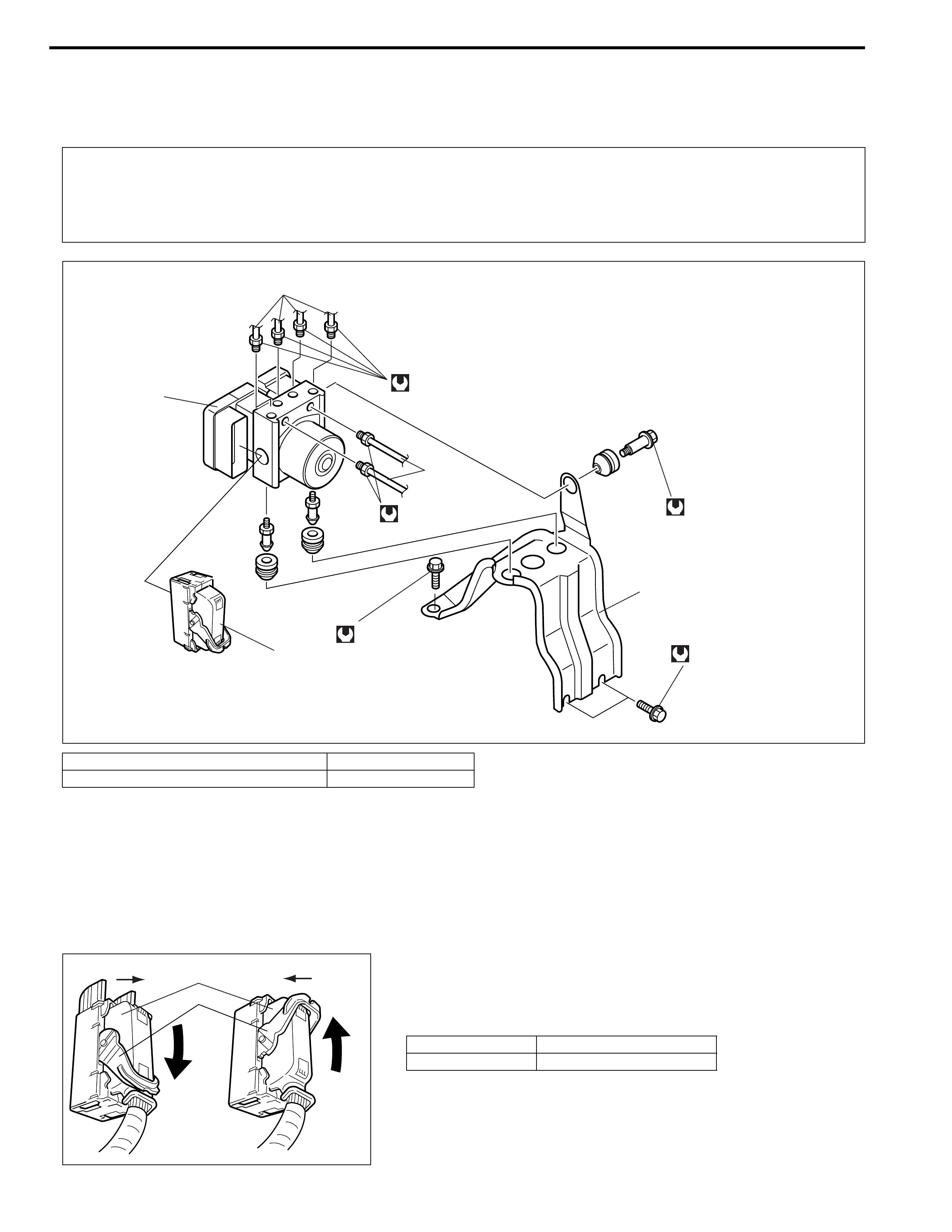
Removal
1) Disconnect negative cable from battery.
2) Disconnect ABS hydraulic unit / control module assembly
connector (1) by pulling down the lock (2).
CAUTION:
Never disassemble ABS hydraulic unit / control module assembly, loosen blind plug or remove motor.
Performing any of these prohibited services will affect original performance of ABS hydraulic unit /
control module assembly.
1. Brake pipe 3. Bracket
2. ABS hydraulic unit / control module assembly 4. Connector
[A]: Disconnect [C]: Pull down to disconnect
[B]: Connect [D]: Pull up to connect
4
16 N·m (1.6 kg-m)
1
9.0 N·m (0.9 kg-m)
16 N·m (1.6 kg-m)
1
9.0 N·m (0.9 kg-m)
9.0 N·m (0.9 kg-m)
2
3
2
1
CD
[A] [B]
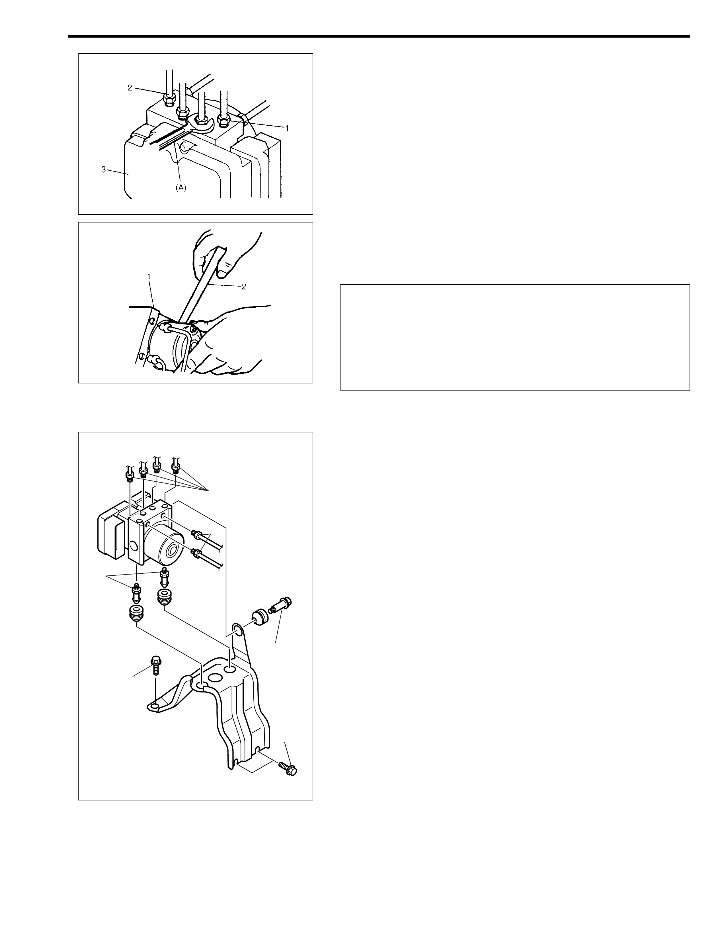
3) Using special tool, loosen flare nuts (1) and disconnect brake
pipes (2) from ABS hydraulic unit / control module assembly
(3).
Special tool
(A): 09950-78220
4) Remove three bolt and disconnect take out ABS hydraulic
unit / control module assembly (1) from bracket using flat end
rod or the like (2).
Installation
1) Install hydraulic unit / control module assembly by reversing
removal procedure.
Tightening torque
Brake pipe flare nut
(a): 16 N·m (1.6 kg-m, 11.5 lb-ft)
ABS hydraulic unit / control module assembly bolt
(b): 9.0 N·m (0.9 kg-m, 6.5 lb-ft)
ABS hydraulic unit / control module assembly bracket bolt
(c): 26 N·m (2.6 kg-m, 19.0 lb-ft)
2) Bleed air from brake system referring to “Air Bleeding of
Brake System” in Section 5.
3) Check each installed part for fluid leakage and perform “ABS
Hydraulic Unit Operation Check” in this section.
NOTE:
Put bleeder plug cap onto pipe to prevent fluid from spill-
ing. Do not allow brake fluid to get on painted surfaces.
CAUTION:
• Do not give an impact to hydraulic unit.
• Use care not to allow dust to enter hydraulic unit.
• Do not place hydraulic unit on its side or upside down.
Handling it in inappropriate way will affect its original
performance.
NOTE:
For new ABS hydraulic unit / control module assembly, if
“ABS Hydraulic Unit Operation Check” procedure has
not been performed, “ABS” warning lamp may flash
when ignition switch is turned ON position.
Accordingly preform “ABS Hydraulic Unit Operation
Check” to stop flashing of ABS warning lamp.
(c)
(c)
(b)
(b)
(a)
(a)
Tightening Torque Specifications
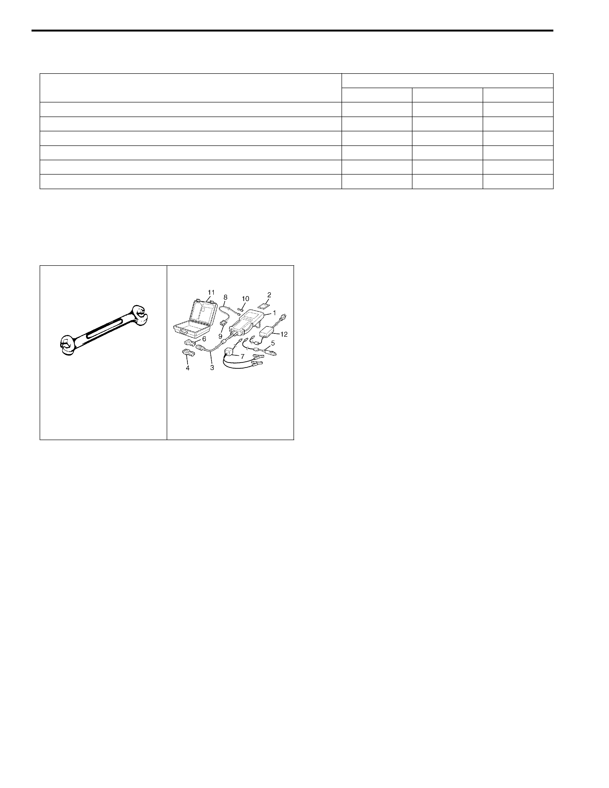
Special Tool
Fastening part
Tightening torque
N•m kg-m lb-ft
Brake pipe flare nut 16 1.6 11.5
ABS hydraulic unit / control module assembly bolt 9.0 0.9 6.5
ABS hydraulic unit / control module assembly bracket bolt 26 2.6 19.0
Front wheel speed sensor bolt 11 1.1 8.0
Front wheel speed sensor clamp bolt 11 1.1 8.0
Rear wheel speed sensor bolt 11 1.1 8.0
09950-78220
Flare nut wrench (10 mm) TECH 2 scan tool (See
NOTE below)
NOTE:
This kit includes the following items.
1. Tech 2, 2. PCMCIA card, 3. DLC cable, 4. SAE 16/19 adapter, 5. Cigarette cable,
6. DLC loopback adapter, 7. Battery power cable, 8. RS232 cable, 9. RS232 adapter,
10. RS232 loopback connector, 11. Storage case, 12. Power supply