
SECTION 6 - ENGINE GENERAL INFORMATION AND
DIAGNOSIS
1. GENERAL INFORMATION
1.1 STATEMENT ON CLEANLINESS AND
CARE
1.2 GENERAL INFORMATION ON ENGINE
SERVICE
1.3 PRECAUTION ON FUEL SYSTEM
SERVICE
1.4 FUEL PRESSURE RELIEF PROCEDURE
1.5 FUEL LEAKAGE CHECK PROCEDURE
2. ENGINE DIAGNOSIS
2.1 GENERAL DESCRIPTION
2.2 ON-BOARD DIAGNOSTIC SYSTEM
Data Link Connector (DLC)
2.3 PRECAUTION IN DIAGNOSING
TROUBLE
2.4 ENGINE DIAGNOSTIC FLOW TABLE
Customer Problem Inspection Form
(Example)
Malfunction Indicator Lamp (MIL)
Check
Diagnostic Trouble Code (DTC)
Check
Diagnostic Trouble Code (DTC)
Clearance
Diagnostic Trouble Code (DTC)
Table
Fail-safe Table
Visual Inspection
Engine Basic Inspection
Engine Diagnosis Table
2.5 TECH 2 DATA
Tech 2 Data Definitions
2.6 INSPECTION OF ECM AND ITS
CIRCUITS
Voltage Check
Resistance Check
2.7 COMPONENT LOCATION
2.8 TABLE A-1 MALFUNCTION INDICATOR
LAMP CIRCUIT CHECK Lamp Does
Illuminate with Ignition Switch ON
(Engine Not Running)
Wiring Diagram
Circuit Description
Inspection
2.9 TABLE A-2 MALFUNCTION INDICATOR
LAMP CIRCUIT CHECK Lamp Remains
ON After Engine Starts
Wiring Diagram / Circuit Description
Inspection
2.10 TABLE A-3 MIL CHECK MIL Flashes With
Ignition Switch ON
Wiring Diagram / Circuit Description
Inspection
2.11 TABLE A-4 MIL CHECK MIL Does Not
Flash or Remains ON Even with
Grounded Diagnosis Switch Terminal
Wiring Diagram / Circuit Description
Inspection
WARNING:
For vehicles equipped with Supplementary Restraint (Airbag) System:
• Service on and around the airbag system components or wiring must be performed only by an
authorised HOLDEN retailer. Refer to AIRBAG SYSTEM COMPONENTS and WIRING LOCATION
VIEW under GENERAL DESCRIPTION in Section 10B AIRBAG SYSTEM in order to confirm
whether you are performing service on or near the airbag system components or wiring. Please
observe all WARNINGS and SERVICE PRECAUTIONS under ON-VEHICLE SERVICE in Section
10B AIRBAG SYSTEM before performing service on or around the airbag system components or
wiring. Failure to follow WARNINGS could result in unintentiona l activation of the system or c ould
render the system inoperative. Either of these two conditions may result in severe injury.
•
Technical service work must be started at least 90 seconds after the ignition switch is turned to
the LOCK position and the negative cable is disconnected from the battery. Otherwise, the sys-
tem may be activated by reserve energy in the Sensing and Diagnostic Module (SDM)
.
IMPORTANT:
Prior to connecting Tech 2 to the vehicle, refer to Section 0C TECH 2.

2.12 TABLE A-5 ECM POWER AND
GROUND CIRCUIT CHECK MIL Doesn’t
Illuminate with Ignition ON and Engine
Won’t Start Though it is Cranked
Wiri ng Diagra m
Circuit Description
Inspection
2.13 DTC P0105 (DTC NO.11) MANIFOLD
ABSOLUTE PRESSURE (MAP) CIRCUIT
MALFUNCTION & DTC P0106 (DTC
NO.11) MANIFOLD ABSOLUTE
PRESSURE (MAP) RANGE /
PERFORMANCE PROBLEM
Wiring Diagram / Circuit Description
DTC Confirmation Procedure
Map Sensor Individual Check
Inspection
2.14 DTC P0110 (DTC NO.18) INTAKE AIR
TEMP. (IAT) CIRCUIT MALFUNCTION
Wiring Diagram / Circuit Description
DTC Confirmation Procedure
Inspection
2.15 DTC P0115 (DTC NO.19) ENGINE
COOLANT TEMPERATURE (ECT)
CIRCUIT MALFUNCTION
Wiring Diagram / Circuit Description
DTC Confirmation Procedure
Inspection
2.16 DTC P0120 (DTC NO.13) THROTTLE
POSITION CIRCUIT MALFUNCTION
Wiring Diagram / Circuit Description
DTC Confirmation Procedure
Inspection
2.17 DTC P0130 (DTC NO.14) HEATED
OXYGEN SENSOR (HO2S) CIRCUIT
MALFUNCTION
Wiring Diagram / Circuit Description
DTC Confirmation Procedure
Inspection
2.18 DTC P0135 (DTC NO.14) HEATED
OXYGEN SENSOR (HO2S) HEATER
CIRCUIT MALFUNCTION
Wiring Diagram / Circuit Description
DTC Confirmation Procedure
Inspection
2.19 DTC P0325 (DTC NO.17) KNOCK
SENSOR CIRCUIT MALFUNCTION
Wiring Diagram / Circuit Description
DTC Confirmation Procedure
Inspection
2.20 DTC P0335 (DTC NO.23) CRANKSHAFT
POSITION (CKP) SENSOR CIRCUIT
MALFUNCTION
Wiring Diagram / Circuit Description
Reference
DTC Confirmation Procedure
Inspection
2.21 DTC P0340 (DTC NO.15) CAMSHAFT
POSITION (CMP) SENSOR CIRCUIT
MALFUNCTION
Wiring Diagram / Circuit Description
Reference
DTC Confirmation Procedure
Inspection
2.22 DTC P0500 (DTC NO.16) VEHICLE
SPEED SENSOR (VSS) MALFUNCTION
Wiring Diagram / Circuit Description
DTC Confirmation Procedure
Inspection
2.23 DTC P1450 BAROMETRIC PRESSURE
SENSOR LOW/HIGH INPUT
Wiring Diagram / Circuit Description
DTC Confirmation Procedure
Inspection
2.24 TABLE B-1 FUEL INJECTOR CIRCUIT
CHECK
Wiring Diagram
Inspection
2.25 TABLE B-2 FUEL PUMP AND CIRCUIT
CHECK
Wiring Diagram
Inspection
2.26 TABLE B-3 FUEL PRESSURE CHECK
Wiring Diagram
Inspection
2.27 TABLE B-4 IDLE AIR CONTROL SYSTEM
CHECK
Inspection
2.28 TABLE B-5 A/C SIGNAL CIRCUITS
CHECK (VEHICLE WITH A/C)
Inspection
2.29 TABLE B-6 ELECTRIC LOAD SIGNAL
CIRCUIT CHECK
Inspection
2.30 TABLE B-7 RADIATOR FAN CONTROL
SYSTEM CHECK
Inspection
3. SPECIAL TOOLS
1. GENERAL INFORMATION
1.1 STATEMENT ON CLEANLINESS AND CARE
An automobile engine is a combination of many machined, honed, polished and lapped surfaces with toler-
ances that are measured in the thousands of a millimetre.
Accordingly, when any internal engine parts are serviced, care and cleanliness are important.
Throughout this Section, it should be understood that proper cleaning and protection of machined surfaces
and fric tion ar eas is part of the repair proced ure. T his is cons ider ed s tandard sho p pra ct ice eve n if not sp ecif-
ically stated.
• A liberal c oating of engin e oil shoul d be applied to fric tion areas d uring assem bly to protect and lubricate
the surfaces on initial operation.
• Whenever valve-train components, pistons, piston rings, connecting rods, rod bearings, and crankshaft
journal bearings are removed for service, they should be retained in order.
At the time of installation, they should be installed in the same locations and with the same mating sur-
faces as when removed.
• Battery cables should be disconnected before any major work is performed on the engine.
Failure to disconnect cables may result in damage to wire harness or other electrical parts.
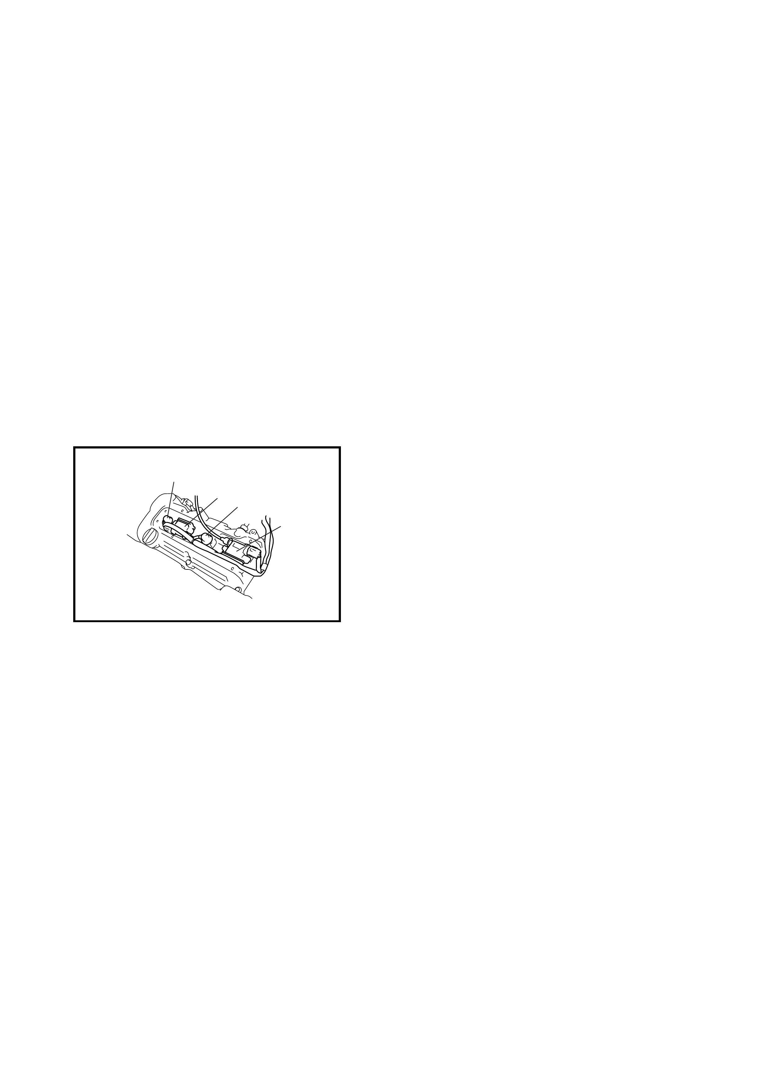
• The four cylinders of the engine are identified by
numbers; No.1 (1), No.2 (2), No.3 (3) and No.4 (4)
counted from crankshaft pulley side to flywheel side.
1.2 GENERAL INFORMATION ON ENGINE SERVICE
THE FOLLOWING INFORMATION ON ENGINE SERVICE SHOULD BE NOTED CAREFULLY, AS IT IS
IMPORTANT IN PREVENTING DAMAGE, AND IN CONTRIBUTING TO RELIABLE ENGINE PERFOR-
MANCE.
• When r aising or supp orting the e ngine for any r eason, do no t use a jack under the oil pan. Due to small
clearance between oil pan and oil pump strainer, jacking against the oil pan may cause it to be bent
against the strainer resulting in a damaged oil pick-up unit.
• It should be k ept in m ind , while wor king o n the engi ne, that t he 12 -v olt el ec tric al syst em i s capable of v io-
lent and damagi ng sh or t circuits.
When performing any work where electrical terminals can be grounded, the ground cable of the battery
should be disconnected at battery.
• Any time the air cleaner, throttle body or intake manifold is removed, the intake opening should be cov-
ered. This will protect against accidental entrance of foreign material which could follow the intake pas-
sage into the cylinders and cause extensive damage when engine is started.
1
23
4
1.3 PRECAUTION ON FUEL SYSTEM S ERVICE
• Work must be done with no smoking, in a well-ventilated area and away from any open flames.
• As the fuel feed line (between fuel pump and fuel delivery pipe) is under high fuel pressure even after
engine wa s stopped, loosenin g or disconn ecting the fuel feed line di rectly may cause a da ngerous spout
of fuel to occur where loosened or disconnected.
Before loosening or disconnecting the fuel feed line, make sure to release the fuel pressure, refer to
1.4 FU EL PRES SU RE RELIE F PRO CED URE. A small amou nt of fuel may be released afte r the fuel lin e
is disconnected. In order to reduce the chance of personal injury, cover the fitting being disconnected with
a shop cloth. Put that cloth in an approved container when disconnection is completed.
• Never run the engine with the fuel pump relay disconnected when the engine and exhaust system are hot.
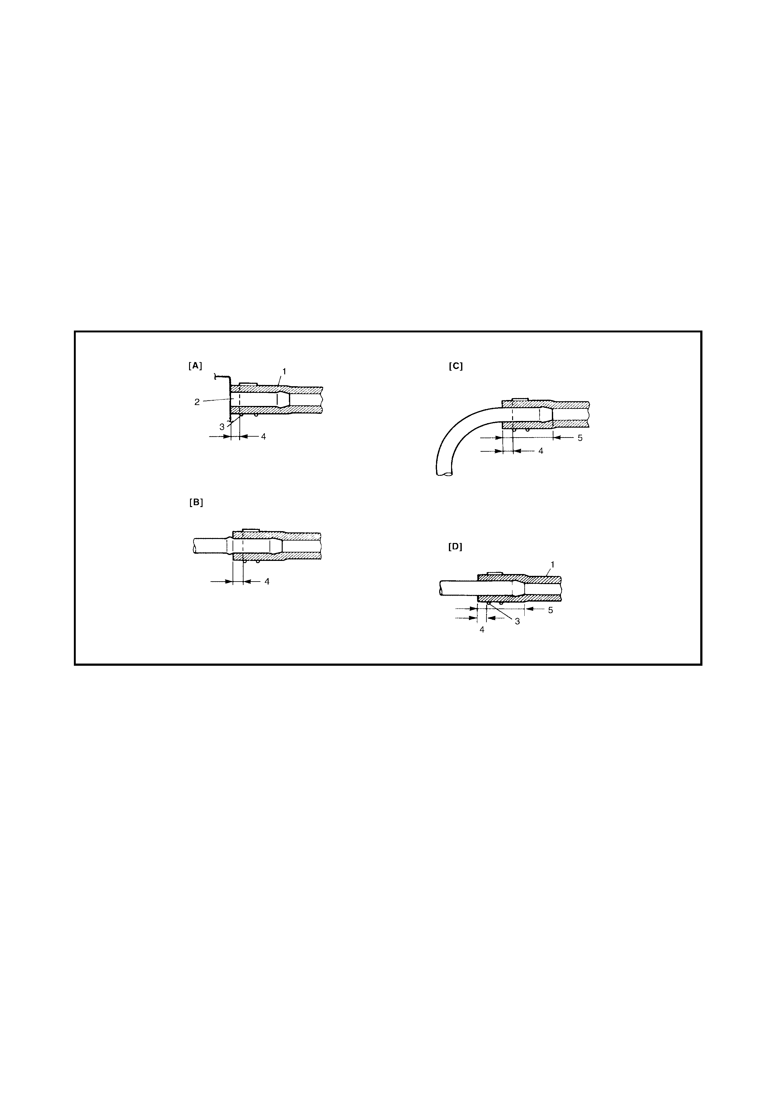
• Fuel or fuel vapour hose connections vary with each type of pipe. When reconnecting a fuel or fuel vapour
hose, connect and clamp each hose correctly, refer to the hose connection figure.
After connecting, make sure that it has no twists or kinks.
• When installing an injector or fuel delivery pipe, lubricate its O-ring with spindle oil or gasoline.
Legend
[A] Short pipe, fit hose fully onto pipe. 1. Hose
[B] Continuing pipe, fit hose onto the projection. 2. Pipe
[C] Bent pipe, fit hose onto bent area or 20 - 30mm. 3. Clamp
[D] Straight pipe, fit hose 20 - 30mm onto the pipe. 4. Clamp securely 3 - 7 mm from hose end
5. 20 - 30 mm
1.4 FUEL PRESSURE RE LIEF PROCEDURE
CAUTION:
This work must not be done when the
engine is hot. If done so, it may cause an adverse
effect to ca talyst.
After maki ng sur e the e ngine is col d, releas e the fuel p res-
sure as follows.
1. Place the transmission in Neutral (P range for A/T), set
the parking brake and the block drive wheels.
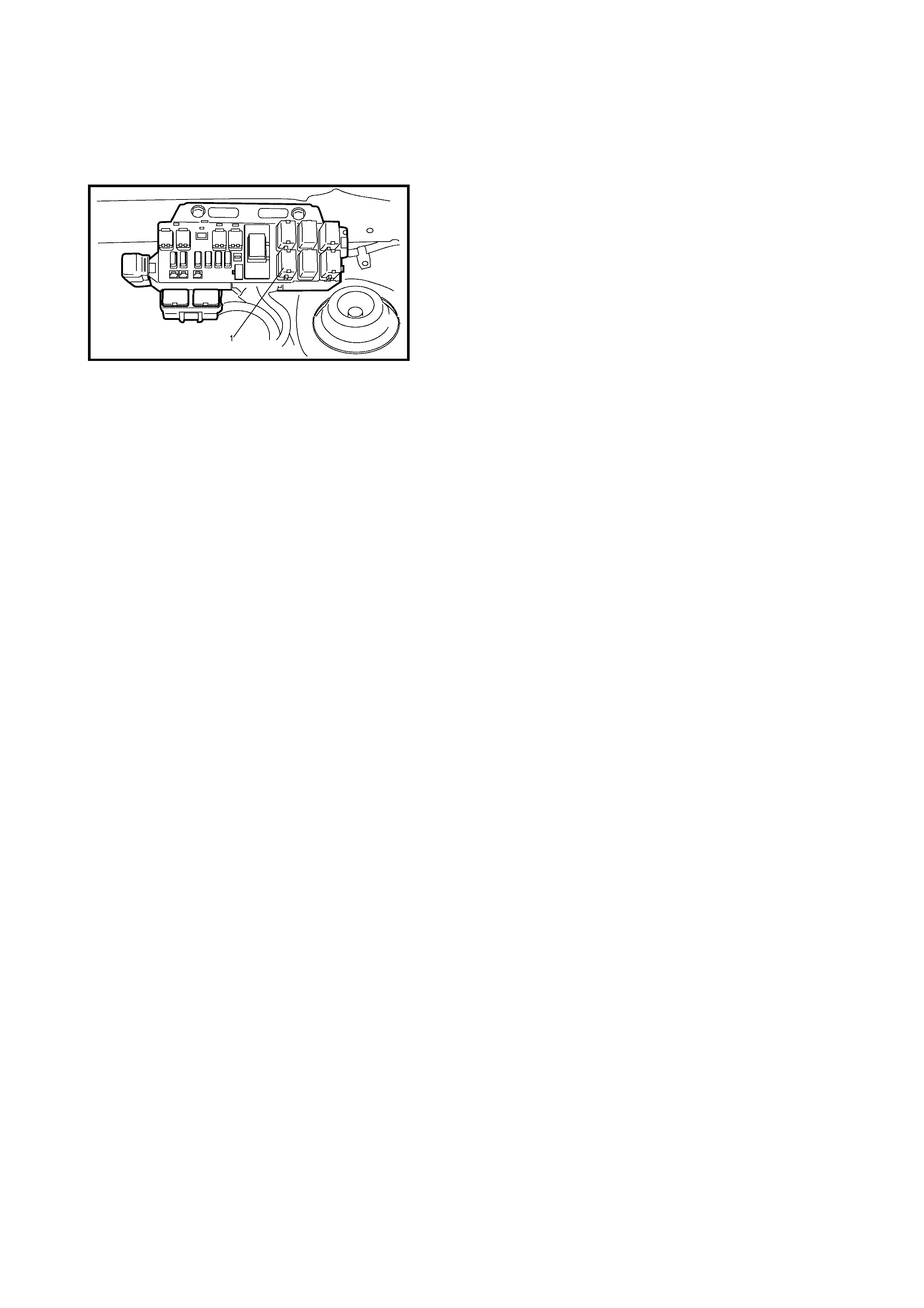
2. Remove the relay box cover.
3. Disconnect the fuel pump relay (1) from the relay box.
4. Remove the fuel filler cap to release fuel vapour
pressure in the fuel tank and then reinstall it.
5. Start the engine and run it unt il it stops for lack of fuel.
Repeat cran king engin e 2-3 times for ab out 3 seconds
each time to dissipate fuel pressure in the lines. Fuel
connections are now safe for servicing.
6. Upon completion of servicing, the connect fuel pump
relay (1) into relay box and install the relay box cover.
1.5 FUEL LE AKAGE CHECK PROCEDURE
After performing any service on the fuel system, check to make sure there are no fuel leakages as follows.
1. Turn the ignition switch ON for 3 seconds (to operate the fuel pump) and then turn it OFF.
Repeat this (ON and OFF) 3 or 4 times and apply fuel pressure to fuel line (until fuel pressure is felt by
hand placed on fuel feed hose).
2. In this state, check to see that there are no fuel leakages from any part of the fuel system.
2. ENGINE DIAGNOSIS
2.1 GENERAL DESCRIPTION
The engine and emission control systems in this vehicle are controlled by the ECM. The ECM has an On-
Board Dia gno sti c sy s tem whic h d ete cts a m al functi on i n th is sys tem and abn or mal ity o f tho se parts that inf lu-
ence the engine exhaust emission. When diagnosing engine troubles, have a full understanding of the outline
of the On-Board Diagnostic System and each item in 2.3 PRECAUTION IN DIAGNOSING TROUBLE and
execute diagnosis according to 2.4 ENGINE DIAGNOSTIC FLOW TABLE.
There is a close relationship between the engine mechanical, engine cooling system, ignition system, exhaust
system, etc. and the engine and emission control system in their structure and operation. In case of an engine
trouble, even when the malfunction indicator lamp (MIL) doesn’t turn ON, it should be diagnosed according to
this flow table.
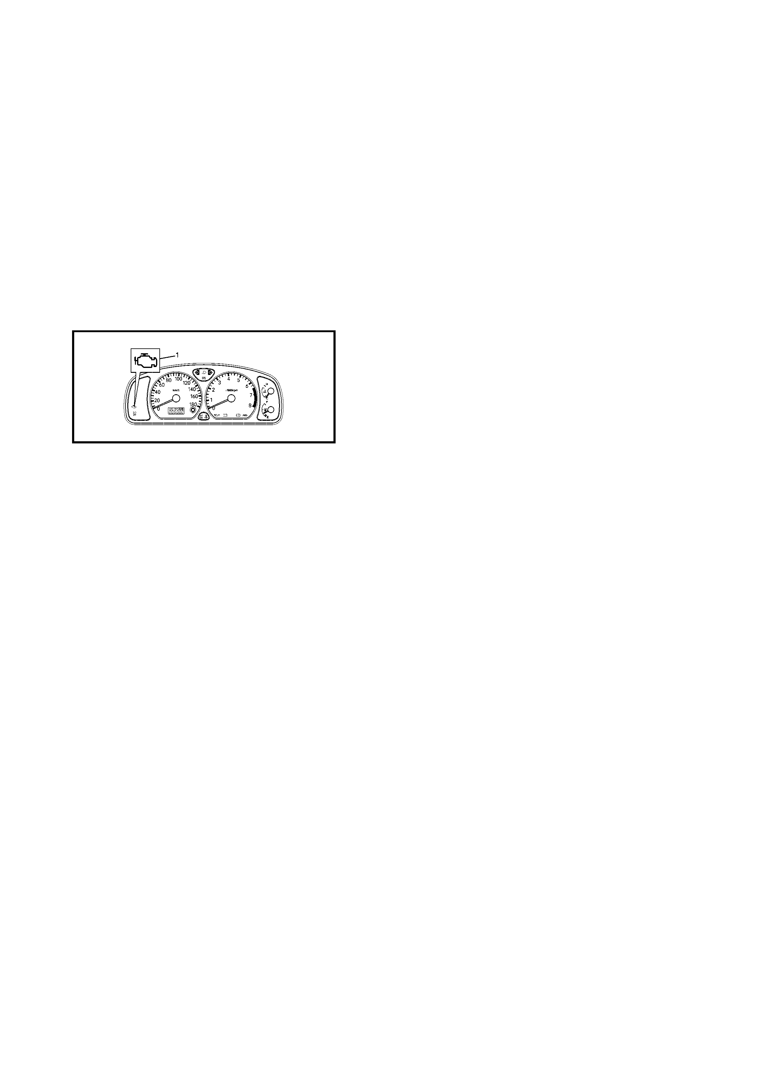
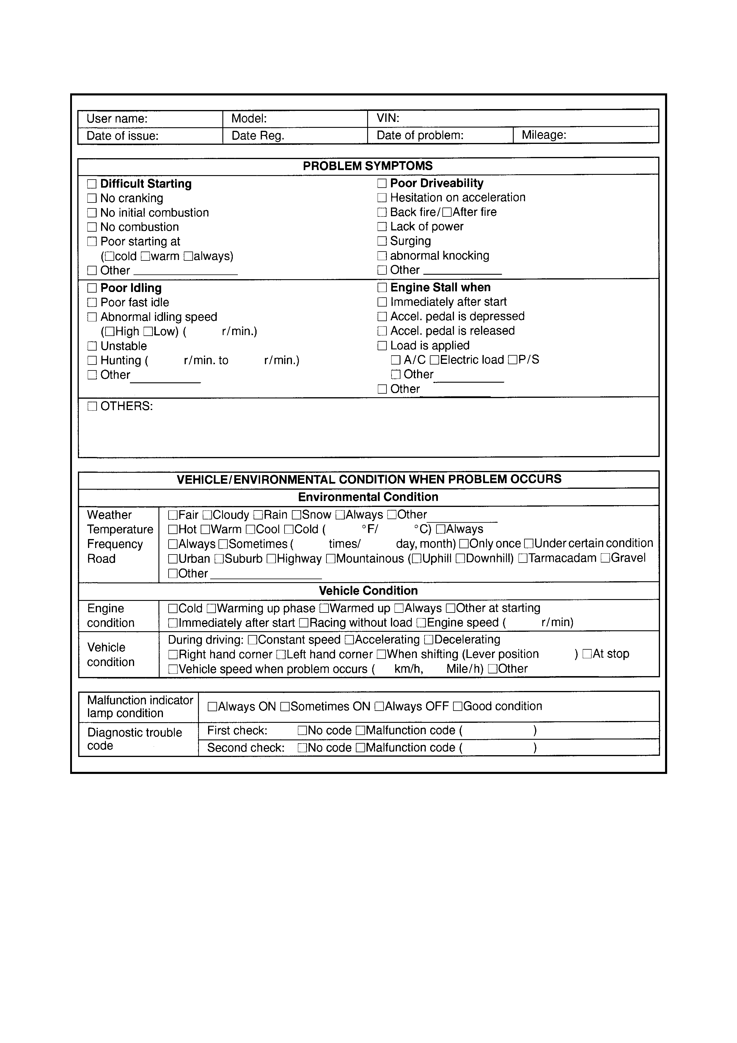
2.2 ON-BOARD DIAGNOSTIC SYSTEM
ECM diagnosis troubles which may occur in the following
areas when the ignition switch is ON and the engine is run-
ning, is indica ted by the tur ning on or fla shing the mal func-
tion indicator lamp (1).
• Heated oxygen sensor
• ECT sensor
• TP sensor
• IAT sensor
• MAP sensor
• CMP sensor
• CKP sensor
• Knock sensor
•VSS
• CPU (Central Processing Unit) of the ECM
The ECM and malfunction indicator lamp operate as fol-
lows:
• Malfunction indicator lamp lights when the ignition
switch is turned ON (but the engine stopped) with the
diagnosis switch terminal ungrounded regardless of
the condition of Engine and Emission control system.
This is only to check the malfunction indicator lamp
bulb and its circuit.
• If the above areas of the engine and emission control
system is free from any trouble after engine start (while
engine is running), the malfunction indicator lamp (1)
turns OFF.
• When the ECM detects a trouble which has occurred in
the above areas, it illuminates the malfunction indicator
while the engine is running to warn the driver of the
occurrence of trouble. At the same time it stores the
trouble area in the ECM back-up memory. (The mem-
ory is kept as it is even if the trouble was only tempo-
rary and disappeared immediately. It is not erased
unless the power to the ECM is shut off for specified
time below.)

• The ECM also indicates the trouble area in memory by
means of flashing of malfunction indicator lamp at the
time of inspection. (i.e. when diagnosis switch terminal
(1) is connected to ground terminal (2) with a service
wire and ignition switch is turned ON.)
NOTE:
• When a trouble occurs in the above areas and disap-
pears while the diagnosis switch terminal is
ungrounded and the engine is running, the malfunction
indicator lamp lights and remains ON as long as the
trouble exists, but it turns OFF when the normal condi-
tion is restored.
• Time required to erase diagnostic trouble code mem-
ory thoroughly varies depending on ambient tempera-
ture as follows.
DATA LINK CONNECTOR (DLC)
The DLC (1) complies with SAEJ1962 in the shape of the
connector and pin assignment.
• Pin 16 (2) is B+.
• Pin 7 (3) is a serial data line (K line of ISO 9141) used
for Tech 2 to communicate with the ECM, TCM, ABS
control module and airbag SDM.
• Pin 5 (4) is ECM ground.
• Pin 4 (5) is body ground.
• Pin 9 (6) is a serial data line used for Tech 2 to commu-
nicate with the immobiliser control module.
2.3 DIAGNOSTIC PRECAUTIONS
• When substituting a known-good ECM, the Immobiliser Control Module and the ECM must be
“Linked” - refer to Section 8G - 6. Registration of ICM and ECM for the correct procedure.
• Do not disconnect the ECM from power or ground before confirming the diagnostic information (DTC,
etc.) stored in the ECM memory. Disconnecting the ECM will erase the ECM memory.
• Diagnostic information stored in the ECM memory can be cleared and checked by using Tech 2. Refer to
Section 0C for the Tech 2 operating procedures .
•Refer to Section 0A - 1.6 PRECAUTIONS FOR ELECTRICAL CIRCUIT SERVICE before commencing
the inspection.
• ECM Replacement:
Check for following conditions. Neglecting this check may cause damage to the known-good ECM.
• Resistance value of all relays, actuators is as s pecified .
• MAP sensor and TP sensor are in good condition and the power circuits of these sensors are not
shorted to gro und .
AMBIENT
TEMPERATURE TIME TO CUT POWER TO ECM
Over 0°C 60 sec. or longer
Under 0°C Not specifiable. Select a place with
higher than 0°C temperature

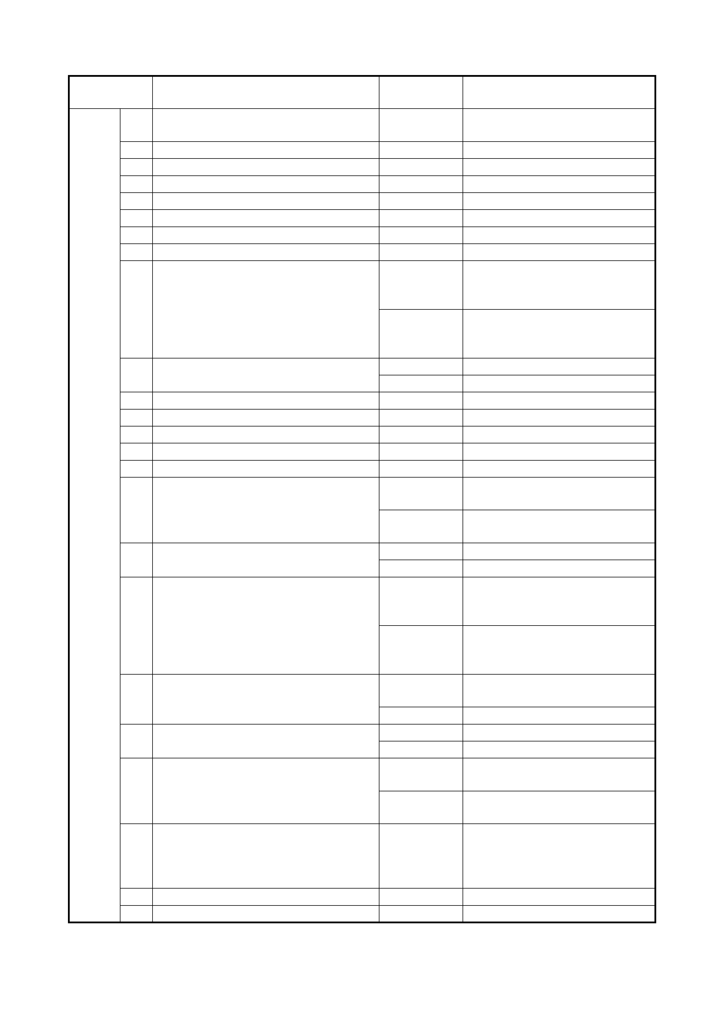
2.4 ENGINE DIAGNOSTIC FLOW TABLE
NOTE: Refer to the following pages for the details of each step.
Step Action Yes No
1Customer Complaint Analysis.
1. Perform customer complaint analysis referring to
the following.
W as customer complaint analysis performed?
Go to S tep 2. Perform customer
complaint analysis.
2DTC Check, Record and Clearance.
1. Check for DTC referring to the following.
Is there any DTC(s)?
Print DTC or write them
down and clear them,
refer to DTC Clearance
in 2.4 ENGINE
DIAGNOSTIC FLOW
TABLE.
Go to Step 3.
Go to Step 4.
3Visual Inspection.
1. Perform visual inspection referring to the
following.
Is there any faulty condition?
Repair or replace mal-
function part.
Go to Step 11.
Go to Step 5.
4Visual Inspection.
1. Perform visual inspection referring to the
following.
Is there any faulty condition?
Go to Step 8.
5Trouble S ymptom Confirmation.
1. Confirm trouble symptom referring to the
following.
Is trouble symptom identified?
Go to Step 6. Go to Step 7.
6Rechecking and Record of DTC.
1. Recheck for DTC, refer to DTC Check in
2.4 ENGINE DIAGNOSTIC FLOW TABLE.
Is there any DTC(s)?
Go to Step 9. Go to Step 8.
7Rechecking and Record of DTC.
1. Recheck for DTC, refer to DTC Check in
2.4 ENGINE DIAGNOSTIC FLOW TABLE.
Is there any DTC(s)?
Go to Step 10.
8Engine Basic Inspection and Engine Diagnosis Table.
1. Check and repair according to Engine Basic
Inspection and Engine Diagnosis Table in
2.4 ENGINE DIAGNOSTIC FLOW TABLE.
Are check and repair complete?
Go to Step 11. Check and repair
malfunction part(s).
Go to Step 11.
9Trouble shooting for DTC.
1. Check and repair according to applicable DTC
diag. flow table.
Are check and repair complete?
10 Check for Intermittent Problems.
1. Check for intermittent problems by referring to the
following.
Is there any faulty condition?
Repair or replace mal-
function part(s).
Go to Step 11.
Go to Step 11.
11 Final Confirmation Test.
1. Clear DTC if any.
2. Perform final confirmation test by referring to the fol-
lowing.
Is there any problem symptom, DTC or abnormal con-
dition?
Go to Step 6. End.

1. Customer Complaint Analysis
Recor d details of the problem (failure, compl aint) and how it oc curred as desc ribed by the custo mer. For this
purpose, use of an inspection form such as follows, will facilitate collecting information to the point required for
proper analysis and diagnosis.
2. DTC Check, Record and Clearance
First, check DTC, refer to DTC Che ck in 2.4 ENGINE DIAG NOSTIC FLOW TA BLE. If DTC is indicated, print
or write it down and then clear them by referring to DTC clearance section. DTC indicates malfunction that
occurred in the system but does not indicat e whether it exists now or it occurred in the past and the normal
condi tion has been resto red now. To ch eck which case appl ies, check the sy mptom in question according to
Step 4 and recheck DTC according to Step 5.
Attempt to diagnose a trouble based on DTC in this step only or failure to clear the DTC in this step will lead to
incorrect diagnosis, trouble diagnosis of a normal circuit or difficulty in troubleshooting.
3. and 4. Visual Inspection
As a preli minary step, per form a visua l check of the ite ms that suppor t proper function of the engine, re fer to
Visual Inspection in 2.4 ENGINE DIAGNOSTIC FLOW TABLE.
5. Trouble Symptom Confirmation
Based on information obtained in Step 1 Customer Complaint Analysis and Step 2 DTC Check, confirm
trouble symptoms. Also, reconfirm DTC according to DTC Confirmation Procedure described in each DTC
Diagnosis Section.
6. and 7. Rechecking and Record of DTC
Refer to DTC Check in 2.4 ENGINE DIAGNOSTIC FLOW TABLE for checking procedure.
8. Engine Basic Inspection and Engine Diagnosis Table
Perform basic engine check according to the Engine Basic Inspection Flow Table in
2.4 ENGINE DIAGNOSTIC FLOW TABLE first. When th e end of the flow table has been rea ched, ch eck the
parts of the system suspected as a possible cause, refer to Engine Diagnosis Table in
2.4 ENGINE DIAGNOSTIC FLOW TABLE and based on symptoms appearing on the vehicle (symptoms
obtained through steps of customer complaint analysis, trouble symptom confirmation and/or basic engine
check) and repair or replace faulty parts, if any.
9. Troubleshooting for DTC (See each DTC Diag. Table)
Based on the DTC indicate d in Step 5 and refe rring to the applica ble DTC Diag . Table in th is Section , locate
the cause of the trouble, namely in a sensor, switch, wire harness, connector, actuator, ECM or other part and
repair or replace faulty parts.
10. Check for Intermitt e nt Problem
Check parts where an intermittent trouble is easy to occur (e.g., wire harness, connector , etc.), refer to
1.7 ELECTRICAL CIRCUIT INSPECTION PROCEDURE - INTERMITTENT AND POOR CONNECTION in
Section 0A and related circuit of DTC recorded in Step 2.
11. Final Confirmati on Test
Confirm that the problem symptom has gone and the engine is free from any abnormal conditions. If what has
been repaired is related to the DTC, clear the DTC once, perform DTC confirmation procedure and confirm
that no DTC is indicated.
CUSTOMER PROBLEM INSPECTION FORM (EXAMPLE)
NOTE:
The abov e form is a st andard samp le. It should be mod ified acco rdin g to condi tions char acte risti c
of each market.
MALFUNCTION INDICATOR LAMP (MIL) CHECK
1. Turn ON ignition switch (with the engine at stop) and
check that the MIL lights.
•If the MIL does not light up (or the MIL dims), go to
Diagnostic Flow Table A-1 for troubleshooting.
•If the MIL flashes, go to Diagnostic Flow Table A-3.
2. Start the engine and check that the MIL turns OFF.
If the MIL remains ON and no DTC is stored in the
ECM, go to Diagnostic Flow Table A-2 for troubleshoot-
ing.
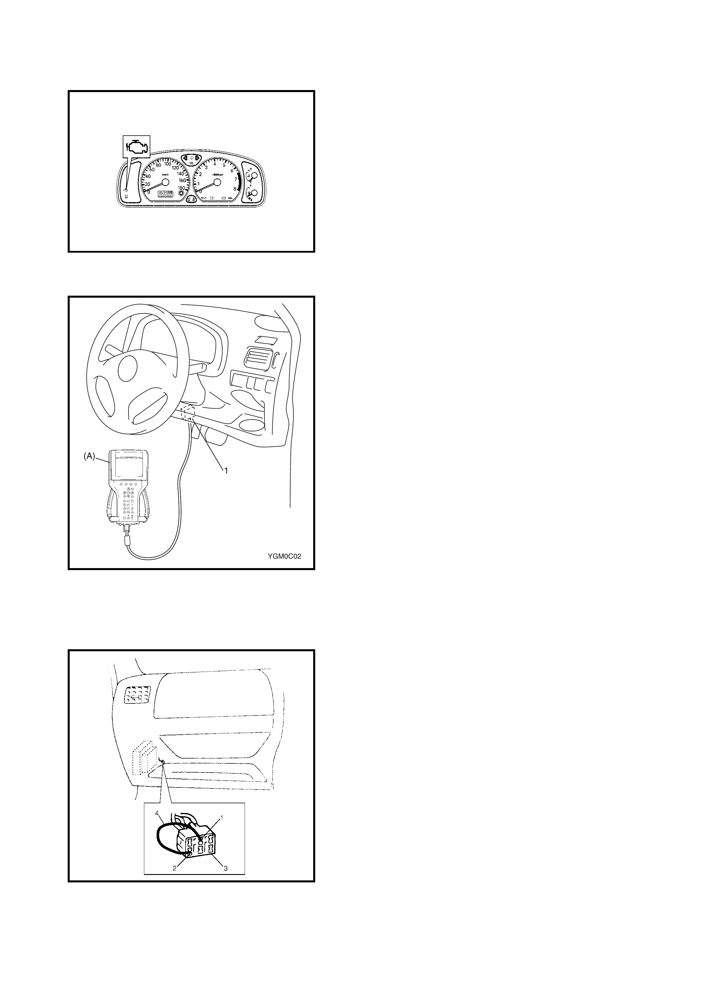
DIAGNOSTIC TROUBLE CODE (DTC) CHECK
[With Tech 2]
1. Prepare Tech 2 (A).
2. With the ignition switch OFF, connect it to data link
connector (DLC) (1) located on underside of the
instrument panel at driver’s side.
3. Turn the ignition switch ON and confirm that the MIL
lights.
4. Read the DTC according to the instructions displayed
on Tech 2 and print it or write it down.
Refer to Tech 2 operator’s manual for further details.
If communication between Tech 2 and the ECM is not
possible, check if Tech 2 is communicable by connect-
ing it to an ECM in another vehicle. If communication is
possible in this case, Tech 2 is in good condition.
Check the data link connector and serial data line
(circuit) in the vehicle with which communication was
not possible.
5. After completing the check, turn ignition switch OFF
and disconnect Tech 2 from data link connector.
[Without Tech 2]
1. Check malfunction indicator lamp, refer to Malfunction
Indicator Lamp Check in
2.4 ENGINE DIAGNOSTIC FLOW TABLE.
2. With the ignition switch OFF, disconnect Tech 2, if
connected and using a service wire (4), connect
diagnosis switch terminal (1) to ground terminal (2) in
diagnosis connector No. 1 (3).
3. With the ignition switch ON and leaving engine OFF,
read the DTC from the flashing pattern of malfunction
indicator lamp. Refer to Diagnostic Trouble Code Table
in 2.4 ENGINE DIAGNOSTIC FLOW TABLE. If the
lamp remains ON, go to Diagnostic Flow Table A-4.
NOTE:
• If an abnormality or malfunction lies in two or more
areas, the malfunction indicator lamp indicates applica-
ble codes three times each.
Flashing of these codes is repeated as long as the
diagnosis terminal is grounded and the ignition switch
is held at the ON position.
• Take a note of the diagnostic trouble code indicated
first.

4. After completing the check, turn the ignition switch
OFF and disconnect the service wire from the
diagno sis connecto r No.1.
DIAGNOSTIC TROUBLE CODE (DTC)
CLEARANCE
With Tech 2
1. Connect Tech 2 to the data link connec tor in the same
manner as when making this connection for a DTC
check.
2. Turn the ignition switch ON.
3. Erase the DTC according to the instructions displayed
on Tech 2. Refer to the Tech 2 operator’s manual for
further details.
4. After comple ting the clearanc e, turn the ignitio n switch
OFF and disconnect Tech 2 from the data link conne c-
tor.
NOTE: A DTC stored in the ECM memory is also cleared
when power to the ECM is cut off by disconnec tin g the bat-
tery cable, removing the fuse or disconnecting the ECM
connectors. Be careful not to clear it before recording DTC.
Without Tech 2
1. Turn the ignition switch OFF.
2. Disconne ct the batter y negative cable for the specifie d
time below to erase any diagnostic trouble code(s)
stored in the ECM memory. Reconnect the battery.
Time require d to erase DTC:
AMBIENT
TEMPERATURE TIME TO CUT POWER TO ECM
Over 0°C 60 sec. or longer
Under 0°C Not specifiable. Select a place with
higher than 0°C temperature
DIAGNOSTIC TROUBLE CODE (DTC) TABLE
NOTE:
• () marked in DTC No. column is DTC which is displayed by flashing malfunction Indicator Lamp (MIL).
• DTC No.12 appears when none of the other codes is identified.
DTC
NO. DETECTING ITEM DETECTING CONDIT ION
(DTC will set whe n detecting:) MIL
P0105
(No.11) Manifold absolute pressure
circuit malfunction Low pressure-high vacuum-low voltage
(or MAP sensor circuit shorted to ground)
High pressure-low vacuum-high voltage (or MAP
sensor circuit open).
1 drivin g
cycle
P0106
(No.11) Manifold absolute pressure
range / perform anc e probl em Variation of input voltage (manifold pressure) is
lower than specification at cold starting. 1 drivin g
cycle
P0110
(No.18) Intake air temp. circuit mal-
function Intake air temp. circuit low input.
Intake air temp. circuit high input. 1 drivin g
cycle
P0115
(No.19) Engine coolant temp. circuit
malfunction Engine coolant temp. circuit low input.
Engine coolant temp. circuit high input. 1 drivin g
cycle
P0120
(No.13) Throttle position circuit mal-
function Throttle position circuit low input.
Throttle position circuit high input. 1 drivin g
cycle
P0130
(No.14) HO2S circuit malfunction Min. output voltage of HO2S-higher than specifica-
tion.
Max. output voltage of HO2S-lower than specifica-
tion.
2 drivin g
cycle
P0135
(No.14) HO2S heater circuit malfunc-
tion Terminal voltage is lower than specification at
heater OFF or it is higher at heater ON. 2 drivin g
cycles
P0325
(No.17) Knock sensor circuit malfunc-
tion Knock sensor circuit low input.
Knock sensor circuit high input. 1 drivin g
cycle
P0335
(No.23) Crankshaft position sens or
circuit malfunction No signal for 2 sec. during engine cranking. 1 driving
cycle
P0340
(No.15) Camshaft position sensor cir-
cuit malfunction No signal during engine running. Mismatch input
signal compared to crankshaft position signal. 1 drivin g
cycle
P0500
(No.16) Vehicle speed sensor mal-
function No signal while running in D range or during fuel cut
at decelerating. 1 drivin g
cycle
P0601
(No.71) Internal control module mem-
ory check sum error Data write error (or check sum error) when written
into ECM. 1 drivin g
cycle
P1450
(No.29) Barometric pressure sensor
circuit malfunction Barometric pressure is lower or higher than specifi-
cation (or sensor malfunction). 1 drivin g
cycle
DTC
NO. DETECTING ITE M DETECTING CONDIT ION
(DTC will set when detecting:) MIL
P1620
(No.84) ECM code not registered Refer to Section 8G, IMMOBILISER CONTROL
SYSTEM
P1621
(No.83) No ECM code transmitted from Immobiliser
Control Module
P1622
(No.82) Fault in ECM
P1623
(No.81) ECM code not matched

FAIL-SAFE TABLE
When a ny of the followin g DTCs are de tected, th e ECM ente rs fail- safe mode for as l ong as the m alfunctio n
continues to exist. That mode is canceled when the ECM detects normal condition.
DTC NO. TROUBLE AREA FAIL-SAFE OPERATION SYMPTOM
P0105 &
P0106
(No.11)
MAP SENSOR ECM uses value determined by
throttle opening and engine speed.
ECM stops EGR, EVAP purge and
idle air control.
Hard starting/ rough or incorrect
idle/ excessive fuel consumption/
hesitation/ poor acceleration/
surge/ detonation or spark knock.
P0110
(No.18) IAT SENSOR ECM controls ac tuato rs a ssum ing
that intake air temperature is 20°C. Hard starting/ rough or incorrect
idle/ excessive fuel consumption/
hesitation poor acceleration/ deto-
nation or spark knock.
P0115
(No.19) ECT SENSOR ECM controls actuators assuming
that engine coolant temperature is
80°C.
Radiator fan motor ON.
Hard starting/ rough or incorrect
idle/ excessive fuel consumption/
hesitation poor acceleration/ deto-
nation or spark knock.
P0120
(No.13) T P SENSO R ECM control s ac tuato rs ass um ing
that throttle opening is 20°. Rough o r in co rr ec t i dl e/ e xce ss iv e
fuel consumption/ hesitation/ poor
acceleration.
P0130
(No.14) HEATED OXYGEN
SENOR – Hard starting/ rough or incorrect
idle/ excessive fuel consumption/
hesitation/ poor acceleration.
P0325
(No.17) KNOCK SENSOR – Detonation/ spark knock.
P0335
(No.23) CKP SENSOR
• Fix ignition timing.
• ECM changes injecti on control
system from sequential injection
to simultaneous one.
Hard starting/ engine stall.
P0340
(No.15) CMP SENSOR ECM changes injection control sys-
tem from sequential injection to
simultaneous one.
Hard starting.
P0500
(No.16) V EH IC L E SP EE D
SENSOR ECM stops idle air control. Rough or incorrect idle.
P0601
(No.71) ECM INTERNAL – Hard starting/ rough or incorrect
idle/ excessive fuel consumption/
detonation or spark knock/ hesita-
tion poor acceleration.
P1450
(No.29) BAROMETRIC
PRESSURE SEN-
SOR
ECM controls actuators assuming
that barometric pressure is
100 kPa (760 mmHg).
Hard starting/ rough or incorrect
idle.

VISUAL INSPECTION
Visually check following parts and systems.
INSPECTION ITEM REFERRING SECTION
• Engine oil – level, leakage. Section 0B
• Engine coolant – level, leakage. Section 0B
• Fuel – level, leakage. Section 0B
• A/T fluid – level, lea ka ge. Section 0B
• Air cleaner element – dirt, clogging. Section 0B
• Battery – fluid level, corrosion of terminal.
• Water pump belt – tension, damage. Section 0B
• Throttle cable – play, installation. Section 6E1
• Vacuum hoses of air intake system – disconnection, loose-
ness, deterioration, bend.
• Connectors of electric wire harness – disconnection, friction.
• Fuses – burning. Section 8
• Parts – installation, bolt – looseness.
• Parts – deformation.
• Other parts that can be checked visually.
• Check following items at engine start, if possible:
•Malfunction indicator lamp – Operation. Section 6
•Charge warning lamp – Operation. Section 6H
•Engine oil pressure warning lamp – Operation. Section 8 (Section 6 for pressure check)
•Engine coolant temp. meter – Operation. Section 8
•Fuel level meter – Operation. Section 8
•Tachometer, if equipped – Operation.
•Abnormal air being inhaled from air intake system.
•Exhaust system – leakage of exhaust gas, noise.

ENGINE BASIC INSPECTION
This check is very important for troubleshooting when ECM has detected no DTC and no abnormality has
been found in visual inspection.
Follow the flow table carefully.
Step Action Yes No
1
Was ENGINE DIAG. FLOW TABLE per-
formed? Go to Step 2. Go to 2.4 ENGINE
DIAG. FLOW TABLE.
2
Check battery voltage.
Is it 11 V or more? Go to Step 3. Charge or replace bat-
tery.
3
Is engi ne cranked? Go to Step 4. Go to 2. DIA GNOSIS in
Section 6G.
4
Does engi ne start? Go to Step 5. Go to Step 7.
5
Check idle speed as follows:
1) War m up engine to normal oper ating
temp.
2) Shift transmission to neutral position for
M/T (P position for A/T).
3) All of electrical loads are switched off.
4) Check engine idle speed with Tech 2.
See Fig. 1.
Is it 6 50 – 750 r/min (70 0 – 800 r/min. fo r A/T
vehicle)?
Go to Step 6. Go to 2.4 ENGINE
DIAGNOSIS TABLE.
6
Check ignition timing as follows:
1) Connect test switch terminal of diagnosis
connector No. 1 to ground. See Fig. 2.
2) Using timing li ght (1), check initial igni-
tion timing. See Fig. 4.
Is it 5° ± 3° BTDC at specified idle speed?
Go to 2.4 ENGINE
DIAGNOSIS TABLE. Check ignition control
relate d parts refer, to
Section 6F1.
7
Is immo biliser control system equipped? Go to Step 8. Go to Step 9.
8
Check immobiliser system malfunct ion as
follows:
1) Check MIL (malfunction indicator lamp)
for flashing.
Is it fl ashing whe n igniti on switch is turned t o
ON position?
Go to 2. DIAGNOSIS in
Section 8G. Go to Step 9.
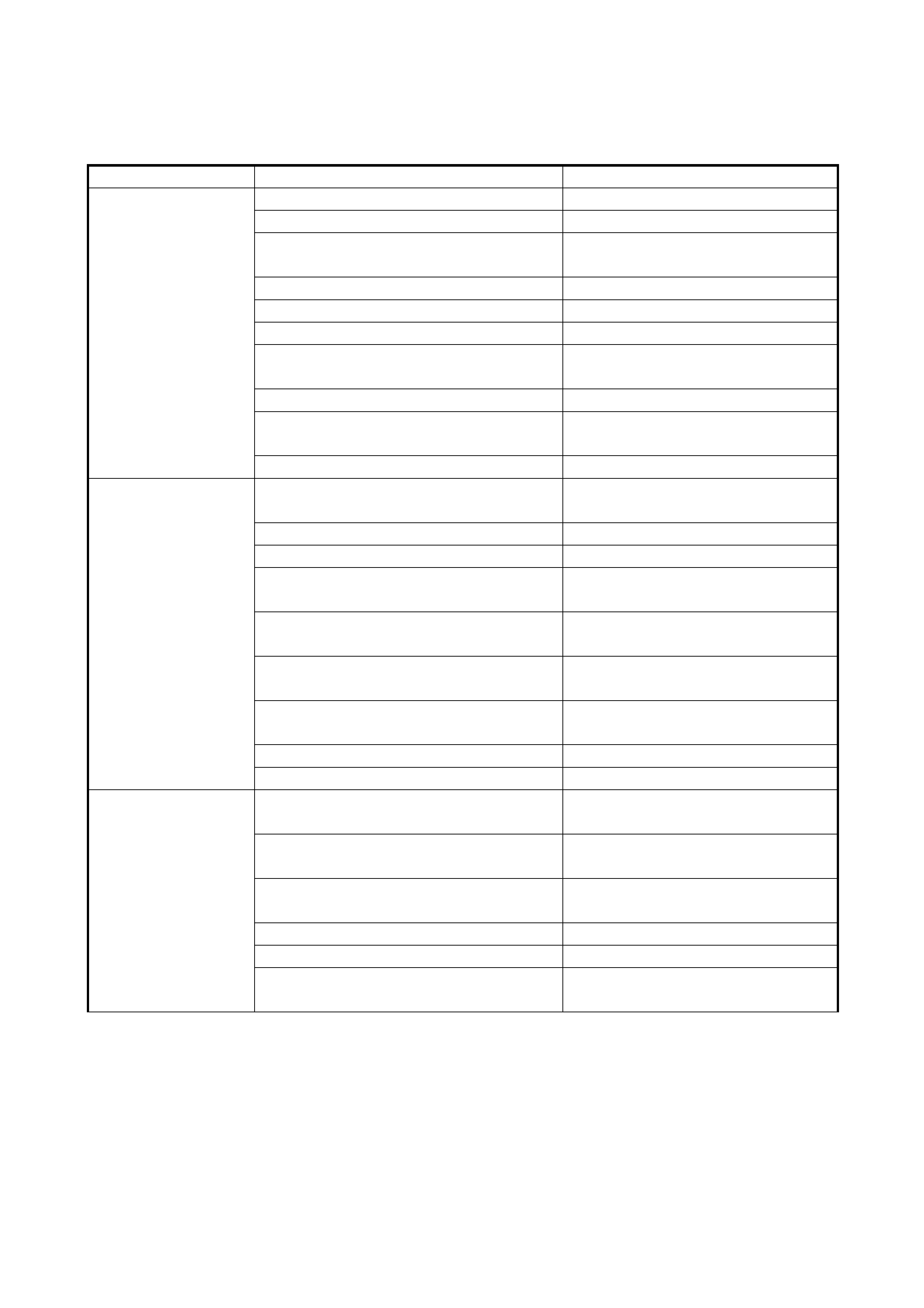
9
Check fuel supply as follow s:
1) Check to make sure that enough fuel is
filled in fuel tank.
2) Turn ON ignition switch for 2 seconds
and then OFF. See Fig. 5.
Is fuel pressure felt from fuel feed hose (1)
when ignition switch is turned ON?
Go to Step 11. Go to Step 10.
10
Check fuel pump for operating.
Was fuel pump operating sound heard from
fuel filler for about 2 seconds after ignition
switch ON and stop?
Go to 2.26 DIAG. FLOW
TABLE B-3. Go to 2.25 DIAG. FLOW
TABLE B-2.
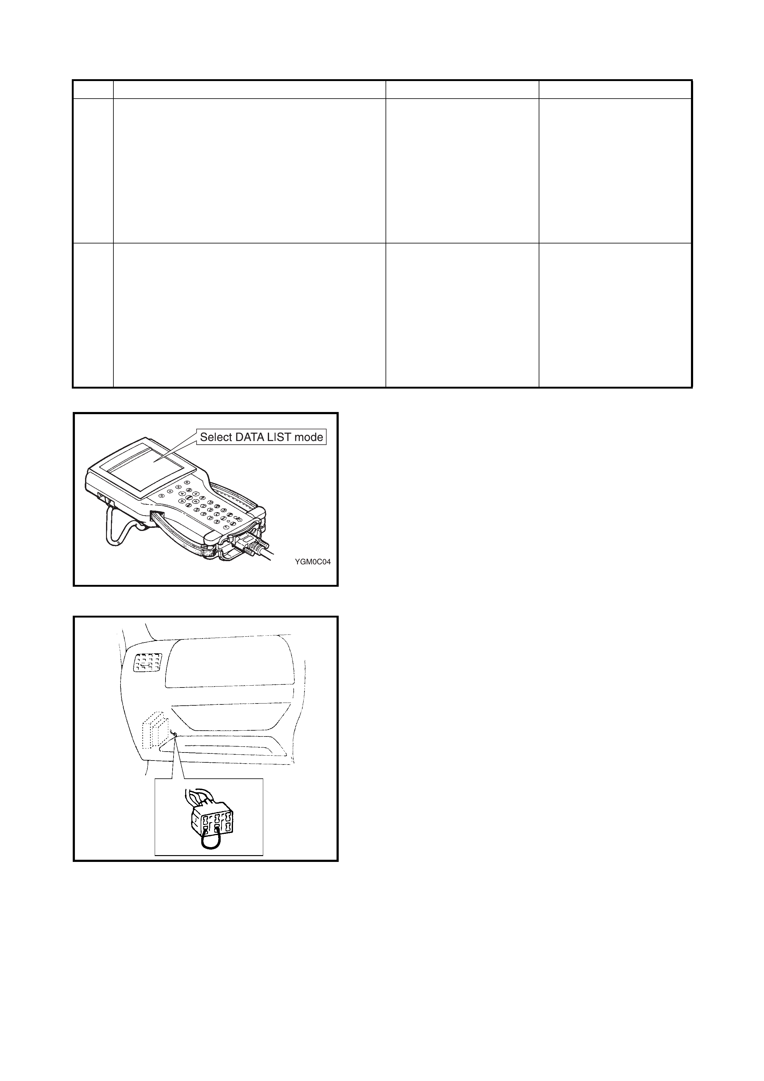
Fig. 1 for Step 5
Fig. 2 for Step 6 when not using Tech 2
11
Check ignition spark as follows:
1) Discon nect injector connectors.
2) Remove spark pl ugs and connect them
to high tension cords.
3) Ground spark plugs.
4) Crank engine and check if each spark
plug sparks.
Is it in good condition?
Go to Step 12. Go to 2. DIAGNOSIS in
Section 6F1.
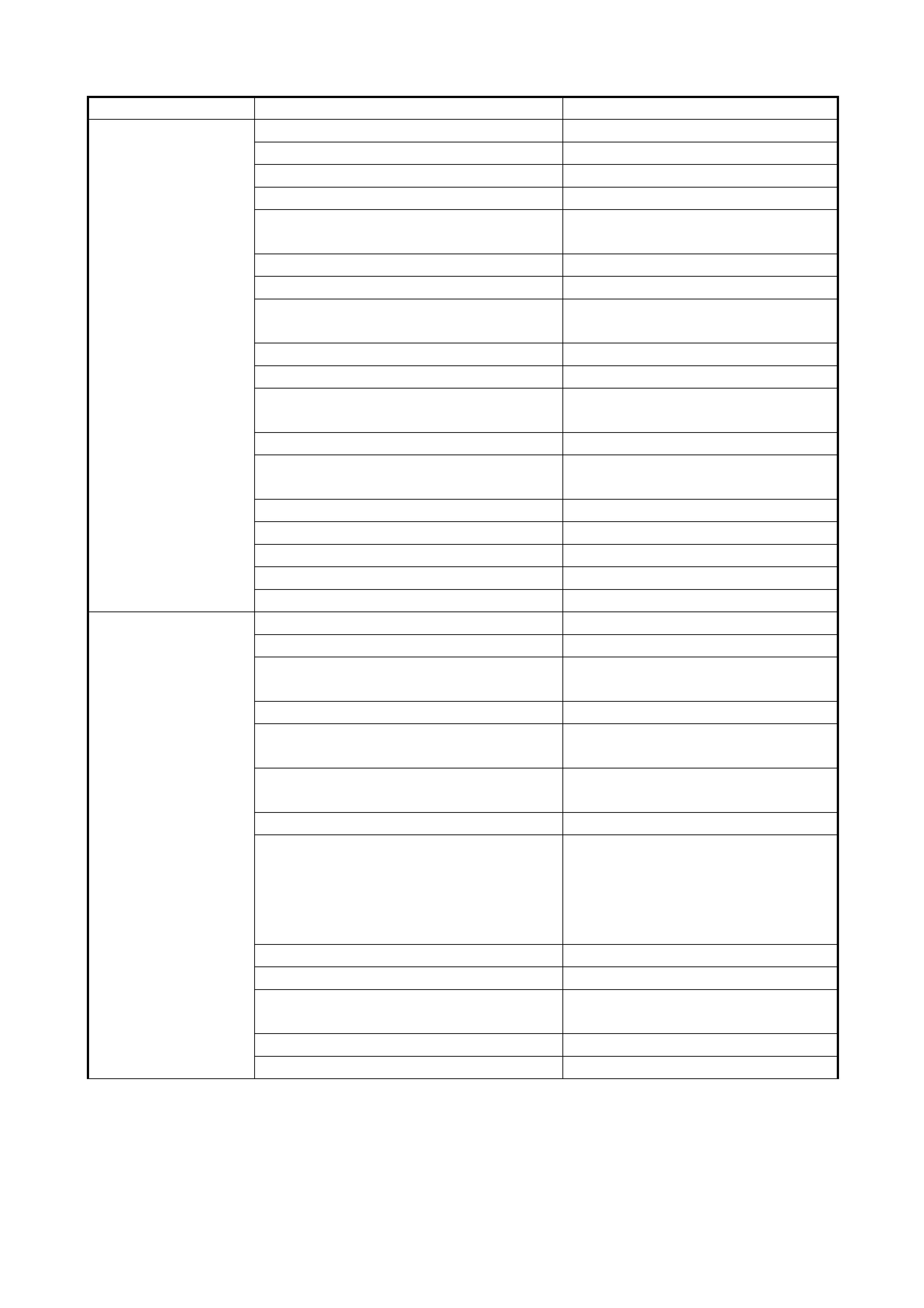
12
Check fuel injector for operation as follows:
1) Install s park plugs an d connect injector
connectors.
2) Using sound scope (1), check operating
sound of each in jector ( 2) when cra nking
engi ne. See Fig. 6.
Was injector operating sound heard from all
injectors?
Go to 2.4 ENGINE
DIAGNOSIS TABLE. Go to 2.24 DIAG. FLOW
TABLE B-1.
Step Action Yes No
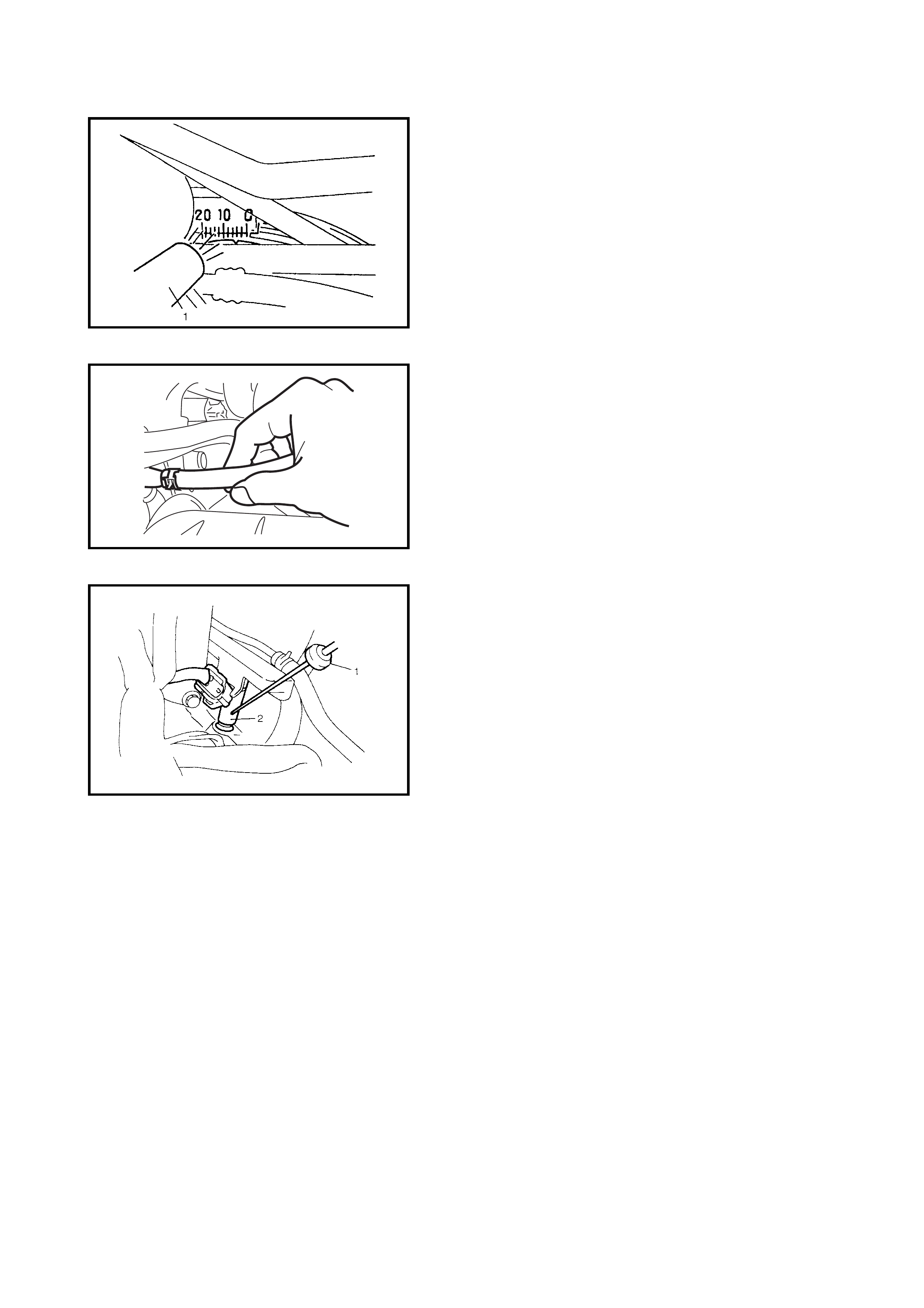
Fig. 4 for Step 6
Fig. 5 for Step 9
Fig. 6 for Step 12
ENGINE DIAGNOSIS TAB LE
Perfo rm troubl eshooting refer ring to followin g table when ECM ha s detec ted no DTC an d no abnormal ity has
been found in visual inspection and engine basic inspection previously.
Condition Possible Cause Correction
Hard Starting
(Engine cranks OK) Faulty spark plug. Spark plugs in Section 6F1.
Leak y high-t ension cord. High-tension cords in Section 6F1.
Loos e connection or disconn ection of
high-t ensio n co rd s or lea d w ire s. High-tension cords in Sect ion 6F1.
Faulty ignition coil. Ignition coil in Section 6F1.
Dirty or clogged fuel hose or pipe. 2.26 Diagnostic Flow Table B-3.
Malfunctioning fuel pump. 2.25 Diagnosti c Flow Table B-2.
Air inhaling from intake manifold gasket
or throttl e bo d y ga s ket.
Faulty idle air control system. 2.27 Diagnostic Flow Table B-4.
Faulty ECT sensor or MAP sensor. ECT sensor or MAP sensor in Sec-
tion 6E1.
Faulty ECM.
Hard Starting
(Engine cranks OK) Poor spark plug tightening or faulty gas-
ket. Spark plugs in Section 6F1.
Compression leak from valve seat. Valves inspection in Section 6A1.
Sticky valve stem. Valves inspection in Section 6A1.
Weak or damaged valve sprin gs. Valve springs inspection in Section
6A1.
Compression leak at cylinder he ad gas-
ket. Cylinder head inspe c tion in Section
6A1.
Sticking or damaged piston ring. Cylinders, pistons and piston rings
inspe c ti on in Se ction 6A1.
Worn piston, ring or cylinder. Cylinders, pistons and piston rings
inspe c ti on in Se ction 6A1.
Malfunctioning PCV valve. PCV system in Section 6E1.
Low compression. Compression check in Section 6A1.
Low oil pressu re Inco rre c t oil vis cos i ty. E n g in e oi l an d oi l fil te r ch an ge in
Section 0B.
Malfunctioning oi l pressure switch. Oil pressure switc h inspection in
Section 8.
Clogged oil str ainer. Oil pan and oil pump strainer clean-
ing in Section 6A1.
Functional deterioration of oil pump. Oil pump in Section 6A1.
Worn oil pump relief valve. Oil pump in Section 6A1.
Excessive clearance in various sliding
parts.

Engine noise
Note: Before
checking mechani-
cal noise, make
sure that :
Specified spark
plug in used.
Specified fuel is
used.
Incorrect valve lash . Valve lash in Section 6A1.
Worn val ve stem and guide. Valves inspection in Sect ion 6A1.
Weak or broken valve spring. Valve springs inspect ion in Section
6A1.
War ped or bent valve. Valves inspection in Section 6A1.
Worn pis ton, ring and cylinder bore. Pistons and cyl inders inspection in
Section 6A1.
Worn ro d bearing. Crank pin and connecting rod bear-
ing inspection in Section 6A1.
Worn crank pin. Crank pin and connecting rod bear-
ing inspection in Section 6A1.
Loos e connecting rod nuts. Connecting rod insta llation in Sec-
tion 6A1.
Low oil pressure. Previously outlined.
Low oil pressure. Previously outlined.
Wo rn bearing . Crank shaft an d bearin g inspect ion in
Section 6A1.
Wo rn crankshaf t journa l. Cranksha ft and be aring i nspection i n
Section 6A1.
Loose bearing cap bolts. Crankshaft inspection in Section
6A1.
Excessive crankshaft thrust play. Crankshaft thrust play i nspection in
Section 6A1.
Overheating Inoperative t hermostat. Ther mostat in Section 6B.
Poor water pump performance. Water pump in Section 6B.
Clogged or leaky radiator. Radiator in Section 6B .
Incorrect engine oil grade. Engine oil and oil filter cha nge in
Section 0B.
Clogged oil filter or oil str ainer. Oil pressure ch eck in Sect ion 6A1.
Poor oil pump performance. Oil pressure check in Section 6A1.
Faulty radiator fan control system. 2.30 Diagnostic flow table B-7
Dragging brakes. Trouble diagnosis in Section 5.
Slipping cl utch. Tr ouble diagnosis in Section 7C.
Blown cylinder head gasket. Cylinder head in Section 6A1.
Condition Possible Cause Correction

Poor gasoline mile-
age Leaks or loose connection of high-tension
cord. High-tension cords in Section 6F1.
Faulty sp ark plug (incorrect gap, heavy
deposits and burned electrodes, etc.). Spark plugs in Section 6F1.
Malfunctioning EGR valve. EGR system in Section 6E1.
High idle speed. Refer to incorrect engine idle speed
previously outlined.
Poor perfo rmance of TP sensor, ECT
sensor or MAP sensor. TP sensor, ECT sensor or MAP sen-
sor i n Section 6E1.
Faulty EGR valve. EGR system in Section 6E1.
Faulty fuel injector(s). Diagnostic Flow Table B-1.
Faulty ECM.
Poor valve seating. Valves inspection in Section 6A1.
Dragging brakes. Trouble diagnosis in Section 5.
Slipping cl utch. Tr ouble diagnosis in Section 7C.
Faulty thermostat. Thermostat in Section 6B.
Incorrect tyre pressure. Refer to Section 3F.
Low Compression. Previously outlined.
Excessive engine
oil co ns um p tion Blown cylinder head gasket. Cylinder head in Section 6A1 .
Leaky camshaft oil seals. Camshaft in Section 6A 1.
Sticky piston ring. Piston cleaning in Sect ion 6A1.
Worn piston and cylinder. Pistons and cylinders inspection in
Section 6A1.
Worn piston ring groo ve and ring. Pistons inspection in Section 6A1.
Improper location of piston ring gap. Pistons assembly in Se ction 6A1.
Worn or damaged valve stem seal. Valves removal and installation in
Section 6A1.
Worn valv e stem. Valves inspection in Section 6A1.
Engine hesitates
(Momentary lack of
response as accel-
erator is depressed .
Can occur at all
vehicle speed s.
Usually most severe
when first trying to
make vehicle move,
as from a sto p
sign.)
Spark plug faulty or plug gap out of
adjustment. Spark plugs in Se ction 6F1.
Leak y high-t ension cord. High-tension cords in Section 6F1.
Fuel pressure out of specification. 2.26 Diagnostic Fl ow Table B-3.
Malfunctioning EGR valve. EGR system in Section 6E1.
Poor perfo rmance of TP sensor, ECT
sensor or MAP sensor. TP sensor, ECT sensor or MAP sen-
sor i n Section 6E1.
Faulty fuel injector. 2.24 Diagnosti c Flow Table B-1.
Faulty ECM.
Engine overheating. Refer to 2. Diagnosis in Section 6B.
Low compression. P reviously outlined.
Surge
(Engine power var i-
ation under stea dy
throttle or cruise.
Feels like vehicle
speeds up and
down with no
change in acce lera-
tor pedal.)
Leak y or loosely connected high-t ension
cord. High-tension cords in Section 6F1.
Faulty sp ark plug (excess carbon dep os-
it s, im proper gap, and bur ned el ectrod es,
etc.).
Spark plugs in Section 6F1.
Variable fuel pressure. 2.26 Diagnostic Flow Table B-3.
Kinked or damaged fuel hose and lines.
Faulty fue l pu m p (clo gg e d fu el filte r).
Malfunctioning EGR valve. EGR system in Section 6E1.
Poor performance of MAP sensor. MAP sensor in Section 6E1.
Faulty fuel injector. 2.24 Diagnosti c Flow Table B-1.
Faulty ECM.
Condition Possible Cause Correction

Excessive detona-
tion
(Engine makes con-
tinuously sharp
metallic knocks that
change with throt-
tle opening. Sounds
lik e pop corn pop-
ping.)
Faulty spark plug. Spark plugs in Section 6F1.
Loos e connection of high-t ension cord. High-tension cords in Section 6F1.
Engine overheating. Refer to 2. Diagnosis in Section 6B.
Clogged fuel filter (faulty fu el pump) or
fuel lines. Diagnostic Flow Table 2.24 B-1 or
2.25 B-2.
Air inhaling fr om intake manifold or throt-
tle body gasket.
Malfunctioning EGR valve. EGR system in Section 6E1.
Poor performance of knock sensor, ECT
sensor or MAP sensor. Knock sensor in Section 6, ECT sen-
sor or MAP sensor in Section 6E1.
Faulty fuel injector(s). 2.24 Diagnostic Flow Table B-1.
Faulty ECM.
Excessive combustion chamber deposits. Piston and cylinder head cleaning in
Section 6A1.
Engine has no
power Faulty spark plug. Spark plugs in Section 6F1.
Faulty ignition coil with ignitor. Ignition coil in Section 6F1.
Leaks, loose co nnection or di sconnectio n
of high-tension cord. High-tensio n cords in Section 6F 1.
Faulty knock sensor. 2.19 Knock sensor malfunction in
this Section.
Clogged fuel hose or pipe. Diagnostic Flow Table B-3.
Malfunctioning f uel pump. Diagnostic Flow Table B-2.
Air inhaling from intake manifold gasket
or throttl e bo d y ga s ket.
Engine overheating. Refer to 2. Diagnosis in Section 6B.
Engine has no
power Malfunctioning EGR valve. EGR system inspection in Section
6E1.
Incorrect accelerator cable play. Accelerator cable play in Section
6E1.
Poor perfo rmance of TP sensor, ECT
sensor or MAP sensor. TP sensor, ECT sensor or MAP sen-
sor i n Section 6E1.
Faulty fuel injector(s). 2.24 Diagnostic Flow Table B-1.
Faulty ECM.
Dragging brakes. Trouble diagnosis in Section 5.
Slipping cl utch. Tr ouble diagnosis in Section 7C.
Low compression. P reviously outlined.
Condition Possible Cause Correction
Impr op er en gi ne
idling or engine fails
to idle
Faulty spark plug. Spark plugs in Section 6F1.
Leak y or disconnected high-tension cord . Hig h-tension cords in Sect ion 6F1.
Faulty ignition coil with ignitor. Ignition coil in Section 6F1.
Fuel pressure out of specification. 2.26 Diagnostic Fl ow Table B-3.
Leak y manifold, throttle body, or cylinder
head gasket.
Malfunctioning EGR valve. EGR system in Section 6E1.
Faulty idle air control system. 2.27 Diagnostic Flow Table B-4.
Faulty evaporative emission control sys-
tem. EVAP contro l system in Section 6E1.
Faulty EGR system. EGR system in Section 6E1.
Faulty fuel injector(s). 2.24 Diagnostic Flow Table B-1.
Poor performance of ECT sensor, TP
sensor or MAP sensor. ECT sensor, TP sensor or MAP sen-
sor i n Section 6E1.
Faulty ECM.
Loos e connection or disconn ection of
vacuum hoses.
Malfunctioning PCV valve. PCV system in Section 6E1.
Engine overheating. Refer to 2. Diagnosis in Section 6B.
Low compression. P reviously outlined.
Faulty electric load signa l circuit. 2.29 Diagnostic Flow Table B-6
Faulty A/C signal circuit. 2.28 Diagnostic Flow Table B-5
Excessive hydro-
carbon (HC) emis-
sion or carbon
monoxide (CO)
Faulty spark plug. Spark plugs in Section 6F1.
Leak y or disconnected high-tension cord . Hig h-tension cords in Sect ion 6F1.
Faulty ignition coil with ignitor. Ignition coil assembly in Section
6F1.
Low compression. Refer to previously outlined.
Lead c onta minatio n of three way cat alyt ic
converter. Check for ab s en c e of fill er ne c k
restrictor.
Faulty evaporative emission control sys-
tem. EVAP contro l system in Section 6E1.
Fuel pressure out of specification. 2.26 Diagnostic Fl ow Table B-3.
Closed loop system (A/F feed back com-
pensation) fails:
• Fault y TP sens or.
• Poor performance of ECT sensor or
MAP sensor.
TP sensor in Section 6E1.
ECT sens or or MAP sensor in Sec-
tion 6E1.
Faulty inje ctor(s). 2.24 Diagnostic Flow Table B-1
Faulty ECM.
Engine not at normal operating tempera-
ture.
Clogged air cleaner.
Vacuum leaks.
Condition Possible Cause Correction
2.5 TECH 2 DATA
As th e data valu es given below are standard val ues est imated on th e basis of value s obtained from the no r-
mally operating v ehicles b y using a Te ch 2, use t hem as r eference v alues. Even when the v ehicle is in good
condition, there may be cases where the checked value does not fall within each specified data range. There-
fore, judgment as abnormal should not be made by checking with this data alone.
Also, conditions in the below table that can be checked by the Tech 2 are those detected by the ECM and out-
put from the ECM as commands. There may be cases where the engine or actuator is not operating (in the
condition) as indicated by the Tech 2. Use a timing light to check the ignition timing.
NOTE:
When checking the data with the engine running at idle or racing, shift M/T gear to the neutral
gear position or A/T gear to the Park position and pull the parking brake ON fully. Also, if nothing or no
load is indicated, turn OFF A/C, all electric loads, P/S and all the other necessary switches.
Excessive nitrogen
oxides (NOx) emis -
sion
Improper ignition timing. See Section 6F1.
Lead contamination of catalytic converter. Check for absence of filler neck
restrictor.
Faulty EGR system. EGR system in Section 6E1.
Fuel pressure out of specification. Diagnostic Flow Table B-3.
Closed loop system (A/F feed back com-
pensation) fails:
• Fault y TP sens or.
• Poor performance of ECT sensor or
MAP sensor.
TP sensor in Section 6E1.
ECT sens or or MAP sensor in Sec-
tion 6E1.
Faulty inje ctor(s). 2.24 Diagnostic Flow Table B-1
Faulty ECM.
Condition Possible Cause Correction
Tech 2 Data Vehicle Condition Normal Condition /
Reference Values
ENGINE LOAD At specified idle speed with no load after
warming up. 3 – 9%
At 2500 r/min. with no load after warming up. 12 – 17%
COOLANT TEMPERATURE At specified idle speed after warming up. 80 – 100°C
SHORT TERM FUEL TRIM At specified idle speed after warming up. – 20 – +20%
LONG TERM FUEL TRIM At specified idle speed after warming up. – 15 – +15%
MANIFOLD ABSOLUTE
PRESSURE At specified idle speed with no load after
warming up. 30 – 37 kPa,
220 – 280 mmHg
ENGINE SPEED At idling with no load after warming up. Desired idle speed
±50 r/min
VEHICLE SPEED At stop. 0 km/h
IGNIT I ON SPARK ADVANC E
(IGNITION TIMING ADV ANCE
FOR NO.1 CYLINDER)
At specified idle speed with no load after
warming up. 6 – 16° BTDC
INTAKE AIR TEMPERATURE At specified idle speed after warming up. Ambient temp. :
+15°C (59°F)
–5°C (23°F)
MASS AIR FLOW At specified idle speed with no load after
warming up. 1 – 4 gm/sec
At 2500 r/min. with no load after warming up. 4 – 9 gm/sec
THROTTLE POSITION Ignition switch
ON/engine
stopped
Throttle valve fully closed 7 – 18%
Throttle valve fully open 70 – 90%
O2 SENSOR 1 At specified idle speed after warming up 0.01 – 0.95 V
DESIRED IDLE SPEED At idling with no load after warming up, M/T
at neutral, A/T at P range M/T 700 r/min
A/T 750 r/min

THROTTLE POSITION SEN-
SOR SIGNAL Ignition switch
ON/engine
stopped
Throttle valve fully closed More than 0.2 V
Throttle valve fully open Less than 4.8 V
INJECTION PULSE WIDTH At specified idle speed with no load after
warming up 2.0 – 3.6 msec.
At 2500 r/min with no load after warming up 2.0 – 3.6 msec.
BAROMETRIC PRESSURE – Display barometric pressure
IDLE AIR CONTROL At idling with no load after warming up 5 – 25%
LONG TERM FUEL TRIM
IDLE At specified idle speed after warming up – 35 – +35%
BATTERY VOLTAGE Ignition switch ON/engine stop 12 – 14 V
CANISTER PURGE PWM – 0 – 100%
EGR PULSE RATIO At specified idle speed after warming up 0%
ECM FUEL CUTOFF When engine is at fuel cut condition ACTIVE
Other than fuel cut condition INACTIVE
FUEL PUMP Within 2 seconds after ignition switch ON or
engine ru nning ACTIVE
Engine stop at ignition switch ON. INACTIVE
RADIATOR COOLING FAN 1 Ignition switch
ON Engine coolant temp. :
Lower than 95°C (203°F) INACTIVE
Engine coolant temp. :
97.5°C (208°F) or higher ACTIVE
APP AT IDLE POSITION
(ACCELERATOR PEDAL
POSITION)
Throttle valve at idle position ACTIVE
Throttle valve opens larger than idle position INACTIVE
PARK/NEUTRAL POSITION
A/T only Ig nition switch
ON Selector lever in P or N
position P - N
Selector lever in R, D, 2 or
L position R - D - 2 - L
STARTER SIGNAL Starter motor cranking ACTIVE
Starter motor not engage INACTIVE
A/C INFORMATION SWITCH Engine running after warming up, A/C not
operating INACTIVE
Engine running after warming up, A/C oper-
ating ACTIVE
EST ADJUSTMENT SWITCH Refer to Section 6F1 ACTIVE / INACTIVE
A/C CLUTCH Ignition switch
ON A/C switch ON ACTIVE
A/C switch OFF INACTIVE
HEATER FAN Ignition switch
ON Heater fan switch ON
(other than 1st speed) ACTIVE
Heater fan switch OFF
(or 1st speed) INACTIVE
BRAKE SWITCH Ignition switch
ON Brake pedal is depressed ACTIVE
Brake pedal is released INACTIVE
O
2
SENSOR At specified idle speed after warming up. ACTIVE (closed loop)
INACTIVE (open loop)
ELECTRIC LOAD Ignition switch ON / Headlight, position light
turned OF F INACTIVE
Ignition switch ON / Headlight turned,
positi on light ON ACTIVE
Tech 2 Data Vehicle Condition Normal Condition /
Reference Values

TECH 2 DATA DEFINITIONS:
Engine Load, %
Engine load displa yed as a percentage of maximum possible load. Value is calculated mathematically using
the formula: actual (current) intake air volume ÷ maximum possible intake air volume x 100%.
Coolant Temperature, °C
It is detected by engine coolant temperature sensor
Short Term Fuel Trim,%
Short term fuel trim value represents short term corrections to the air/fuel mixture computation. A value of 0
indicates no correction, a value greater than 0 means a rich mixture correction, and a value less than 0
implies a lean mixture correction.
Long Term Fuel Trim,%
Long term fuel trim value represents long term corrections to the air/fuel mixture computation. A value of 0
indicates no correction, a value greater than 0 indicates a rich mixture correction, and a value less than 0 indi-
cates a lean mixture correction.
Manifold Absolute Pressure, kPa
Detected by the manifold absolute pressure sensor and used (among other things) to compute engine load.
Engine Speed, RPM
It is computed by reference pulses from crankshaft position sensor.
Vehicle Speed, km/h
It is computed based on pulse signals from vehicle speed sensor.
Ignition Spark Advance (Ignition Timing Advance For No.1 Cylinder), °CA
Ignition timing of No.1 cylinder is commanded b y the ECM. The actual ignition timing should be checked by
usin g a timing light.
Intake Air Temperature,°C
It is detected by the intake air temperature sensor and used to determine the amount of air passing into the
intake manifold as air density varies with temperature.
Mass Air Flow, g/s
It represents total mass of air entering intake manifold which is computed based on signals from MAP sensor,
IAT sensor, TP sensor, etc.
Throttle Position, %
When th rottle positio n sensor is a t the fully closed position, thro ttle opening is indicated as 0% and 100% at
the full open position.
O2 Sensor 1, mV
It indicates output voltage of HO2S installed on exhaust manifold (pre-catalyst).
Desired Idle Speed, RPM
The Desired Idle S peed is an ECM internal parameter which indicates the ECM requested idle. If the engine is
not running, this number is not valid.
Throttle Positi on Sensor Signal, V
The Throttle Position Sensor reading provides throttle valve opening information in the form of voltage.
Injection Pulse Wi dth, ms
This parameter indicates the time of the No.1 cylinder injector drive pulse (valve opening) which is output from
the ECM.
Barometric Pressure , kPa
Displays barometric pressure.
Idle Air Control, %
This parameter ind ic ate s cu rre nt flo w t ime ra te with in a cer tain se t cycle of the IAC valv e (va lv e ope ning r ate)
which controls the amount of bypass air (idle speed).
Long Term Fuel Trim Idle, %
The va lue of Long Te rm Fuel Trim is obtained by put ting value s of short Term F uel Trim and Long Term Fuel
Trim together. This value indicates how much correction is necessary to keep the air/fuel mixture stoichiomet-
rical.

Battery Volt age, V
This parameter indicates battery positive voltage inputted from main relay to ECM.
Canister Purge PWM, %
This parameter ind ic ate s valv e O N (val v e open ) time rate with in a c er tain set cycl e of cani st er purge s ole noi d
valve which controls the amount of EVAP purge.
0% means that the purge valve is completely closed while 100% is a fully open valve.
EGR Pulse Ratio, %
This parameter indicates opening rate of EGR valve which controls the amount of EGR flow.
Fuel Cutoff, Acti ve/Inactive
ACTIVE: Fuel being cut (output signal to injector is stopped)
INACTIVE: Fuel not being cut
Fuel Pump, Active/I nactive
ACTIVE: Fuel pump running.
INACTIVE: Fuel pump stopped.
Radiator Cooling Fan 1, Active/Inactive
ACTIVE: Command for radiator fan control relay operation being output.
INACTIVE: Command for relay operation not being output.
APP at Idle Position (Accelerator Pedal Posit ion), Active/Inactive
This parameter will re ad AC TI VE when thr o ttle val ve is fully clos ed, or INA CTIVE when the thr ottl e is not ful ly
closed.
Park/Neutral Position (A/T Only), P-N range or R-D-2-L range
It is detected by a signal from TCM.
R-D-2-L range: A/T is in R, D, 2 or L range.
P-N range: A/T is in P or N range or the above signal is not inputted from TCM.
Starter Signal, Active/Inactive
ACTIV E: Starter motor cranki ng.
INACTIVE: Starter motor not engaged.
A/C In fo r m a t io n S w itch , Ac tive/ In a c tive
ACTIVE: Command for A/C operation being output from ECM to A/C amplifier.
INACTIVE: Command for A/C operation not being output.
EST Adjustment Switch, Active/ Inactive
Refer to Section 6F1.
A/C Clutch (Air Conditioning), Active/Inactive
ACTIVE: A/C switch ON.
INACTIVE: A/C switch OFF.
Heater Fan, Active/Inactive
ACTIVE: Heater fan ON (other than 1st speed)
INACTIVE: Heater fan OFF or on 1st speed.
Brake Switch, Active/Inactive
ACTIVE: Brake pedal depressed.
INACTIVE: Brake pedal released.
O2 Sensor, Active/Inactive
Air/fuel ratio feedback loop status displayed as either open (inactive) or closed (active) loop.
INACTIVE (open loop) indicates that the ECM ignores feedback from the exhaust oxygen sensor.
ACTIVE (closed loop) indicates final injection duration is corrected for oxygen sensor feedback.
Electric Load, Active/Inactive
ACTIVE: Headlight, position light ON signal inputted.
INACTIVE: Above electric loads all turned OFF.
2.6 INSPECTION OF ECM AND ITS CIRCUITS
The ECM and its circuits can be checked at the ECM wiring
connectors by measuring voltage and resistance.
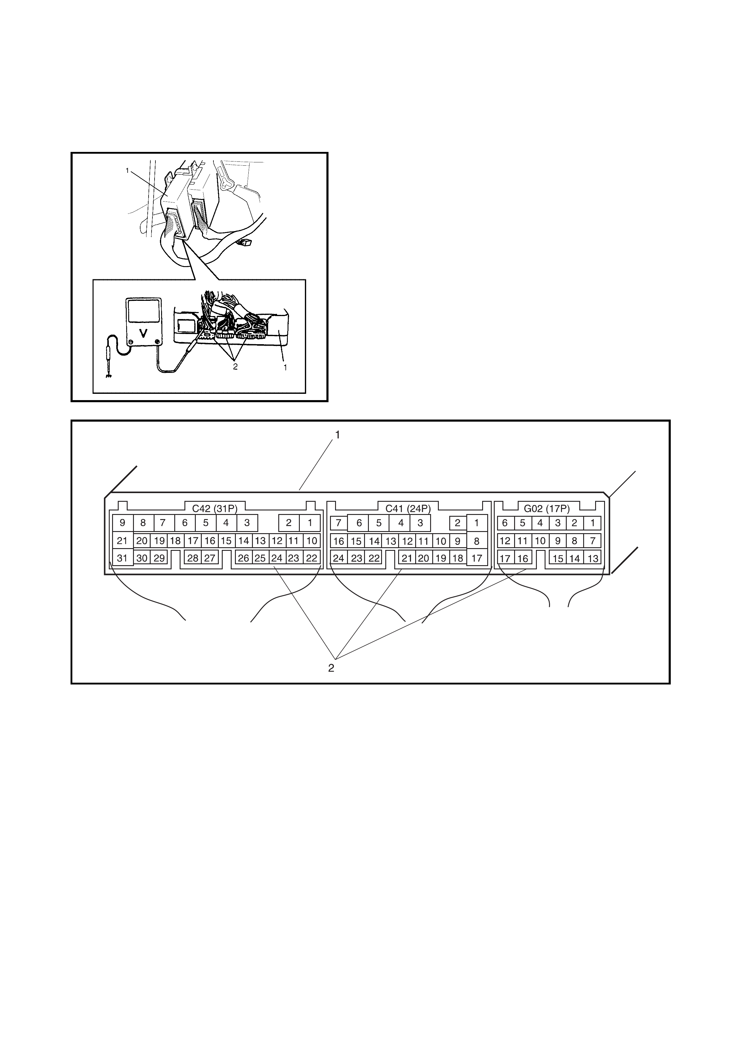
CAUTION: The
ECM cannot be checked by itself. It is
strictly prohibited to connect a voltmeter or ohm
mete r to the ECM with connector discon nected.
VOLTAGE CHECK
1. Remove the ECM (1) from the vehicle, refer to
1.3 ELECTRONIC CONTROL SYSTEM in
Section 6E1 .
2. Check the vo ltage at each co nnect or term inal ( 2) whil e
connected.
NOTE:
As each terminal voltage is affected by the bat-
tery voltage, confirm that it is 11 V or more when the
ignition switch is ON.
Legend
1. ECM
2. ECM connectors viewed from harness side

TERMINAL
NO. CIRCUIT NORMAL
VOLTAGE CONDITION
C42 1 Ground – –
2 Ground – –
3 Ground – –
4 EVAP canister purge valve 10 – 14 V Ignition switch ON
5Blank – –
6 Idle air control valve 0 – 13 V At specified idle speed after engine
warmed up
7 Heater of HO2S 10 – 14 V Ignition switch ON
8 Fuel injector No.4 10 – 14 V Ignition switch ON
9 Fuel injector No.1 10 – 14 V Ignition switch ON
10 Sensor ground – –
11 Camshaft position sensor 0 – 0.8 V and
4 – 6 V Ignition switch ON
12 Shield ground – –
13 Heated oxygen sensor Refer to DTC P0130 diag. flow table
14 Engine coolant temp. sensor 0.55 – 0.95 V Ignition switch ON
Engine coolant temp.: 80°C
15 Intake air temp. sensor 2.0 – 2.7 V Ignition switch ON
Intake air temp.: 20°C
16 Throttle position sensor 0.2 – 1.0 V Ignition switch ON
Throttle valve at idle position
2.8 – 4.8 V Ignition switch ON
Throttle valve at full open position
17 EGR valve (Stepper motor coil 3) 10 – 14 V Ignition switch ON
18 EGR valve (Stepper motor coil 1) 10 – 14 V Ignition switch ON
19 Ignition coil #2 – –
20 Ignition coil #1 – –
21 Fuel injector No.2 10 – 14 V Ignition switch ON
22 Power source for sensor 4.75 – 5.25 V Ignition switch ON
23 Crankshaft position sensor – –
24 – – –
25 Shield ground – –
26 Manifold absolute pressure sensor 3.3 – 4.0 V Ignition switch ON
Barometric pressure: 100 kPa (760
mmHg)
27 Diag. Switch terminal 4 – 6 V Ignition switch ON
28 EGR valve (Stepper motor coil 4) 10 – 14 V Ignition switch ON
29 EGR valve (Stepper motor coil 2) 10 – 14 V Ignition switch ON
30 Blank – –
31 Fuel injector No.3 10 – 14 V Ignition switch ON
TERMINAL
NO. CIRCUIT NORMAL
VOLTAGE CONDITION
C41 1 A/C compressor clutch and condenser
fan relay 0 V Ignition switch ON
2 Blank – –
3 Blank – –
4 Blank – –
5 Power source 10 – 14 V Ignition switch ON
6 Power source 10 – 14 V Ignition switch ON
7 Power source for back-up 10 – 14 V Anytime
8 Diagnostic connector No. 1 output – –
9 Radiator fan control relay 10 – 14 V Ignition switch ON and engine
coolant temperature 100°C or
lower
0 – 1 V Ignition switch ON and engine
coolant temperature 102.5°C or
higher
10 Main re lay 10 – 14 V Ignition switch OFF
0.4 – 1.5 V Ignition switch ON
11 Ignition switch 10 – 14 V Ignition switch ON
12 Blank – –
13 Blank – –
14 Diag. switch terminal 4 – 6 V Ignition switch ON
15 Test switch terminal 4 – 6 V Ignition switch ON
16 A/C (input) signal 10 – 14 V Ignition switch ON
A/C switch OFF
0 – 2 V Ignition switch ON
A/C switch ON
17 Electric load signal (+) 0 V Ignition switch ON, small light OFF
10 – 14 V Ignition switch ON, small light ON
18 Radiator fan control relay 10 – 14 V Ignition swi tch ON
Engine coolant temp.: 9.5°C or
lower
0 – 1 V Ignition switch ON
Engine coolant temp.: 97.5°C or
higher
19 Fuel pump relay 0 – 1 V For 2 seconds after ignition switch
ON
10 – 14 V After the above time
20 Engine start switch (engine start signal) 6 – 12 V While engine cranking
0 V Other than above
21 Stop lamp switch 0 V Ignition switch ON, stop lamp
switch OFF
10 – 14 V Ignition switch ON, stop lamp
switch ON
22 Vehicle speed sensor Indicator
deflection
repeated 0 V
and 4 – 6 V
Ignition switch ON
Front left wheel turned slowly with
front right wheel locked
23 Blank – –
24 Blank – –

RESISTANCE CHECK
1. Turn ignition switch OFF.
1. Disconnect the ECM connectors (1) from the ECM.
CAUTION:
Never to uch terminals of th e ECM.
2. Check resistance between each connector terminal
with an ohmmeter (2).
CAUTION:
• Connect ohmmeter probe from wiring harnes s side
of connector.
• Resistance in the table below represents parts at
20°C.
TERMINAL
NO. CIRCUIT NORMAL
VOLTAGE CONDITION
G02 1 A/C evaporator outlet air temp. sen-
sor ––
2Blank – –
3Blank – –
4 A/C on/off output (A/T) 0 – 1 V A/C compressor operating
5 Engine torque sign al outp ut (A/T) Indicator
deflection
repeated 0V
and 10 – 14 V
Engine running at idle speed
6 D range idle-up signal (A/T) 10 – 14 V Ignition switch ON
7 Data link connector (serial data line) 4 – 6 V Ignition switch ON
8Blank – –
9 Malfunction indicator lamp (MIL) 0 – 1 V Ignition switch ON
10 – 14 V Engine running
10 Blank – –
11 Data link connector (K-line of
ISO 9141) 10 – 14 V Ignition switch ON
12 Torque signal output (A/T) Indicator
deflection
repeated 0V
and 10 – 14 V
Ignition switc h ON
13 Electric load signal (–) 0 – 2 V Ignition switch ON
Blower fan turned OFF
10 – 14 V Ignition switch ON
Blower fan turned ON
14 Ground for sensor – –
15 Throttle opening signal for TCM Indicator
deflection
repeated 0V
and 10 – 14 V
Ignition switc h ON
16 Tachometer 0 – 1 V Ignition switch ON
17 Coolant temp. signal output (A/T) Indicator
deflection
repeated 0V
and 10 – 14 V
Ignition switc h ON

TERMINALS CIRCUIT STANDARD
RESISTANCE
C42-7 to C41-11 HO2S 5.0 – 6.4 Ω
C42-9 to C41-5/6 No.1 injector 11.3 – 13.8 Ω
C42-21 to C41-5/6 No.2 injector 11.3 – 13.8 Ω
C42-31 to C41-5/6 No.3 injector 11.3 – 13.8 Ω
C42-8 to C41-5/6 No.4 injector 11.3 – 13.8 Ω
C42-28 to C41-5/6 EGR valve (stepper motor coil 4) 20 – 24 Ω
C42-17 to C41-5/6 EGR valve (stepper motor coil 3) 20 – 24 Ω
C42-29 to C41-5/6 EGR valve (stepper motor coil 2) 20 – 24 Ω
C42-18 to C41-5/6 EGR valve (stepper motor coil 1) 20 – 24 Ω
C42-4 to C41-5/6 EVAP canister purge valve 30 – 34 Ω
C41-19 to C41-11 Fuel pump relay 56 – 146 Ω
C41-18 to C41-5/6 Radiator fan control relay No.1 56 – 146 Ω
C41-10 to C41-7 Main relay 56 – 146 Ω
C42-1 to Body ground Ground Continuity
C42-2 to Body ground Ground Continuity
C42-3 to Body ground Ground Continuity
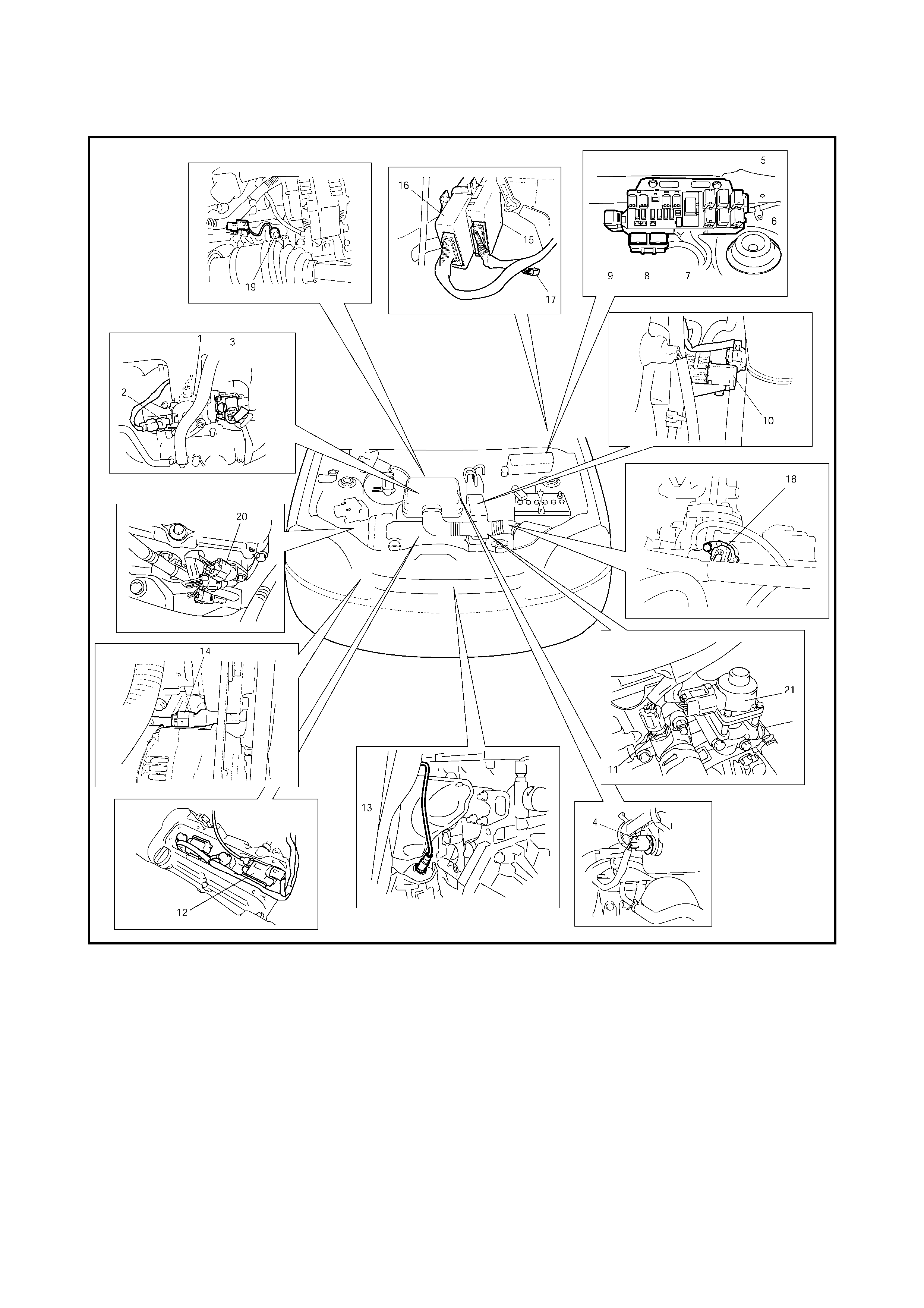
2.7 COMPONENT LOCATION
Legend
1. TP sensor 8. Radiator fan control relay No.2 15. TCM
2. MAP sensor 9. Radiator fan control relay No.3 16. ECM
3. IAC valve 10. EVAP canister purge valve 17. Diagnosis connector No.1
4. IAT sensor 11. ECT sensor 18. VSS
5. Radiator fan control relay
No.1 12. Ignition coil with igniter 19. Knock sensor
6. Main relay 13. HO2S 20. CMP sensor
7. Fuel pump relay 14. CKP sensor 21. EGR valve
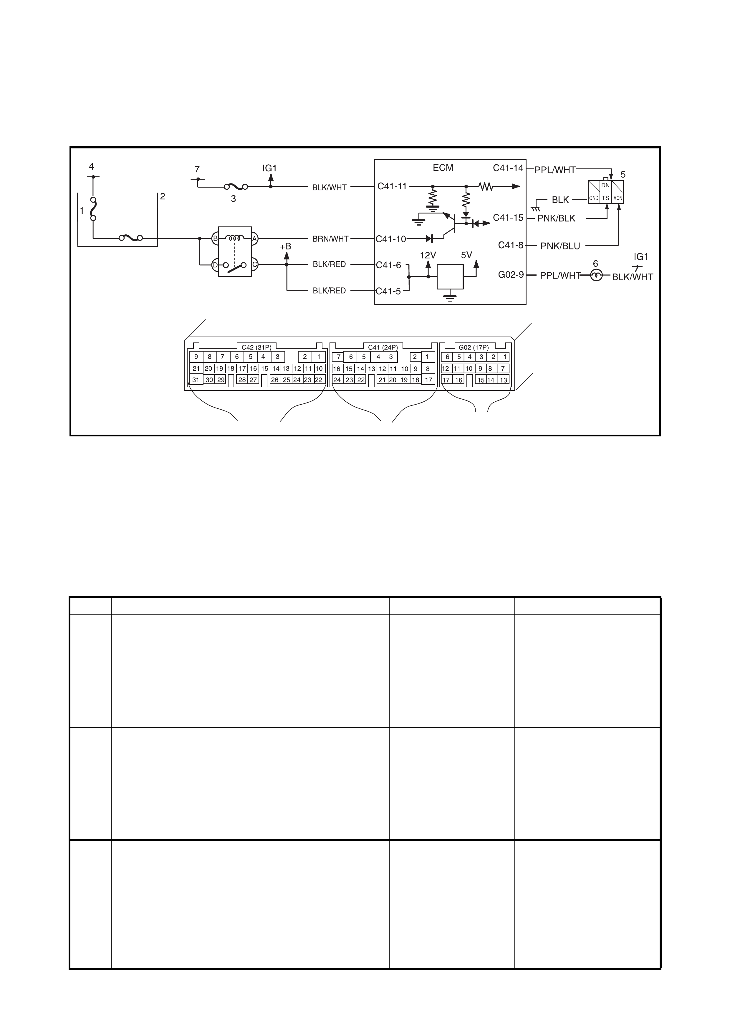
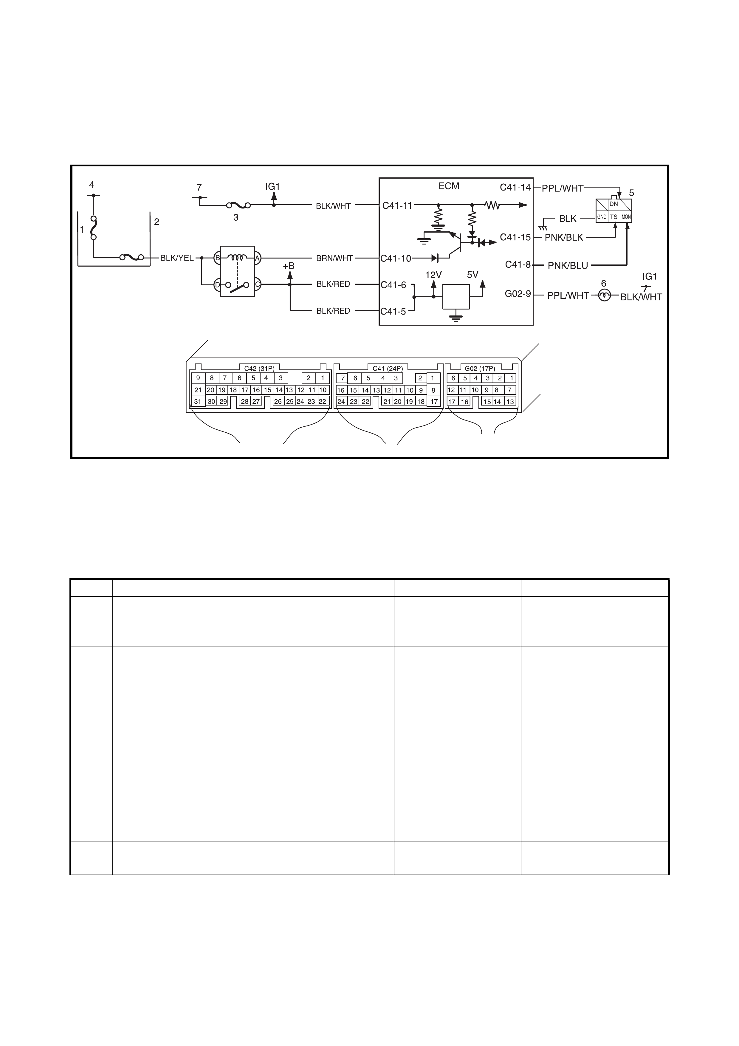
2.8 TABLE A-1 MALFUNCTION INDICATOR LAMP CIRCUIT CHECK LAMP
DOES ILLUMINATE WITH IGNITION SWITCH ON (EN GINE NOT RUNNING)
WIRING DIAGRAM
Legend
CIRCUIT DESCRIPTION
When the ignition switch is turned ON, the EC M causes the main relay to turn ON (close the contact point).
Then, with the ECM being supplied with the main power, it turns ON the malfunction indicator lamp (MIL).
When t he eng ine starts to run and no ma lfunctio n is de tected in th e system, the MIL goes OFF, but if a mal-
function was or is detected, the MIL remains ON even when the engine is running.
INSPECTION
1. BATT fuse 3. IG fuse 5. Diagnosis connector
No. 1 6. MIL
2. Main fuse box 4. To battery 7. To ignition switch
Step Action Yes No
1 MIL Power Supply Check.
1) Turn ignition switch ON.
Do other indicator/warning lights in combination
meter comes ON?
Go to Step 2. IG fuse blown, main fuse
blown, ignition switch
malfunction, BLK/WHT
circuit between IG fuse
and combination meter or
poor coupler connection
at combinati on meter.
2 ECM Power and Ground Circuit Check.
Does engine start? Go to Step 3. Go to 2.12 TABLE A-5
ECM POWER AND
GROUND CIRCUIT
CHECK.
If engine is not cranked,
go to 2. DIAGNOSIS in
Section 6G.
3 MIL Circuit Check.
1) Turn ignition switch OFF and disconnect con-
nectors from ECM.
2) Check for proper connection to ECM at termi-
nal G02-9.
3) If OK, then using service wire, ground terminal
G02-9 in disconnected connector.
Does MIL turn on at ignition switch ON?
Substitute a known-
good ECM and
recheck.
Bulb burned out or PPL/
WHT wire circuit open.
Test switch terminal cir-
cuit grounded

2.9 TABLE A-2 MALFUNCTION INDICATOR LAMP CIRCUIT CHECK
LAMP REMAINS ON AFTER ENGINE STARTS
WIRING DIAGRAM / CIRCUIT DESCRIPTION
Refer to TABL E A-1.
INSPECTION
Step Action Yes No
1
Diagnostic Trouble Code (DT C) Check.
1) Check DTC, refer to 2.4 ENGINE
DIAGNOSTIC FLOW TABLE.
Is there any DTC(s)?
Go to Step 2 of 2.4
ENGINE DIAGNOS-
TIC FLOW TABLE .
Go to Step 2.
2
DTC Check.
1) St a r t en gine a nd r ec hec k DTC while e ngi ne
running.
Is there any DTC(s)?
Go to Step 3.
3
MIL Circuit Check.
1) Turn OFF ignition switch.
2) Disconnect con nectors from EC M.
Does MIL turn ON at ignition switch ON?
PPL/WHT wire cir-
cuit shorted to
ground.
Substitute a known-
good ECM and recheck.

2.10 TABLE A- 3 MIL CHECK
MIL FLASHES WITH IGNITION SWITCH ON
WIRING DIAGRAM / CIRCUIT DESCRIPTION
Refer to TABL E A-1.
INSPECTION
Step Action Yes No
1
MIL Flashing Pattern Check.
1) Turn ignition switch ON.
Does lamp flashing p attern indicate diagnostic
trouble cod e?
Go to Step 2. Substitut e a known-
good ECM and recheck.
2
Diag. Switch Circuit Check.
Is dia g. switch terminal connecte d to groun d via
service wire?
System is in good
condition. PPL/WHT circuit
shorted to ground. If cir-
cuit is OK substitute a
known-good ECM and
recheck.

2.11 TABLE A-4 MIL CHECK MIL DOES NOT FLASH OR REMAINS ON EVEN WITH
GROUNDED DIAGNOSIS SWITCH TERMINAL
WIRING DIAGRAM / CIRCUIT DESCRIPTION
Refer to TABL E A-1.
INSPECTION
Step Action Yes No
1
MIL Circuit Check.
1) Turn ignition switch OFF and disconnect
connectors from ECM.
Does MIL turn ON at ignition switch ON?
PPL/WHT ci rc ui t
shorted to ground. Go to Step 2.
2
ECM Conn ection Check.
1) Turn ignition switc h OFF.
Is connector C41-14 connected to ECM prop-
erly?
Go to Step 3. Poor connector c onnec-
tion.
3
Diag. Switch Terminal Circuit Check.
1) Connect connectors to ECM.
2) Using se rvice wire, ground C41-14 terminal
with connectors connected to ECM.
3) Turn ignition switch ON.
Does MIL flash?
PPL/WHT or BLK
circuit open. Substi tute a known-
good ECM and recheck.
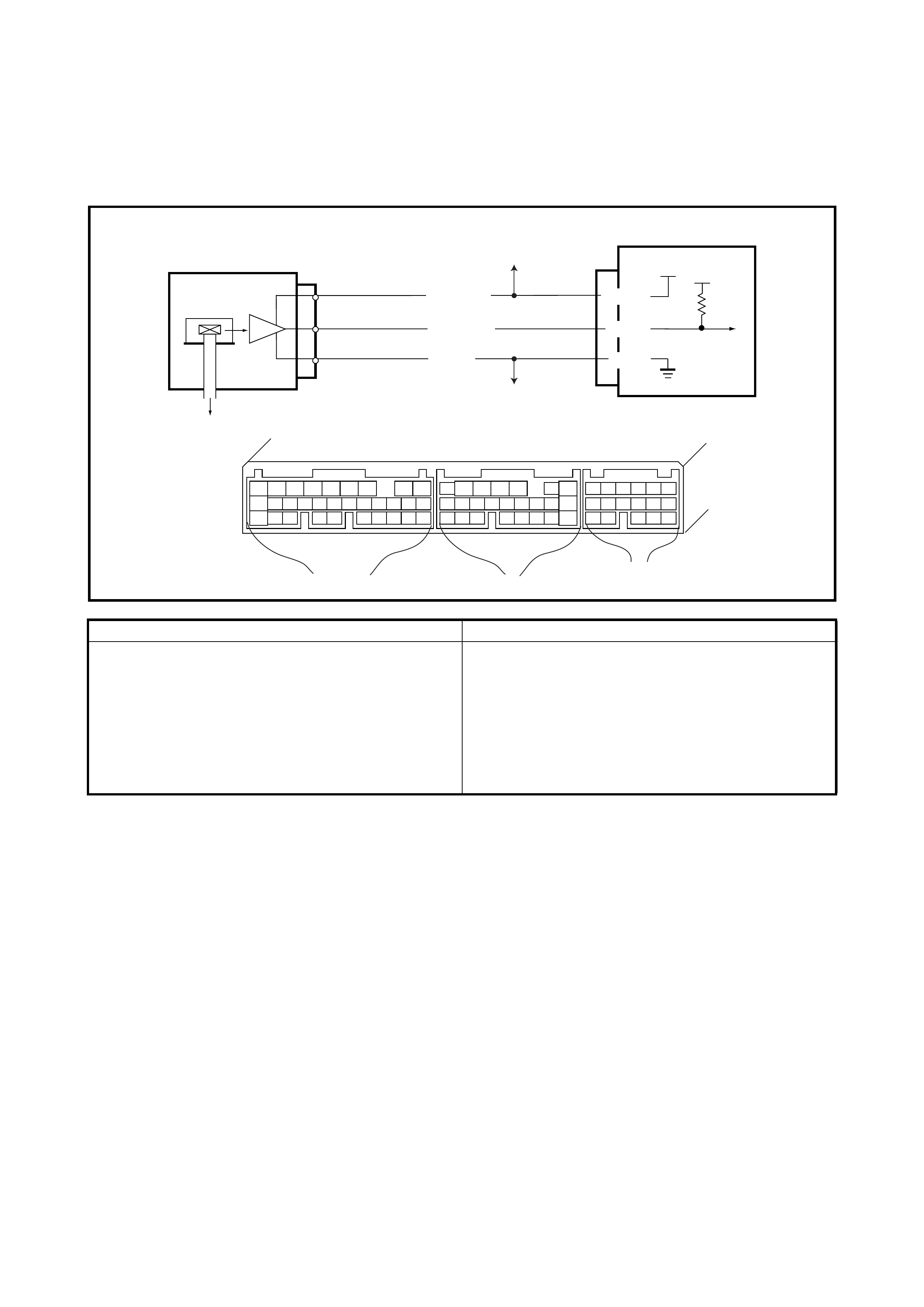
2.12 TABLE A-5 ECM POWE R AND GROUND CIRCUIT CHECK
MIL DOESN’T ILLUMINATE WITH IGNITION ON AND ENGINE WON’T S TART THOUGH
IT IS CRANKED
WIRING DIAGRAM
CIRCUIT DESCRIPTION
When the ig nit ion s wi tch tu ned O N, the main r el ay tu rns O N ( th e c on tact p oin t c l oses ) and th e mai n powe r is
supplied to ECM.
INSPECTION
1. BATT fuse 3. IG fuse 5. Diagnosis connector No. 1
2. Main fuse box 4. To battery 6. MIL
Step Action Yes No
1 Main Relay Operating Sound Check.
Is operating sound of main relay heard at ignition
switch ON?
Go to Step 5. Go to Step 2.
2 Main Relay Check.
1) Turn OFF ignition switch and remove main
relay (1).
2) Check for proper connection to main relay (1).
3) Check resistance between each two
terminals. See Fig. 1 and 2.
Between terminals C and D: Infinity
Between terminals A and B: 56 – 146 Ω
4) Check that there is continuity between
terminals C and D when battery is connected
to terminals A and B. See Fig. 3.
Is main relay in good condition?
Go to Step 3. Replace main relay.
3 Fuse Check.
Is main fuse in good condition? See Fig. 4. Go to Step 4. Check for short in circuits
connected to this fuse.
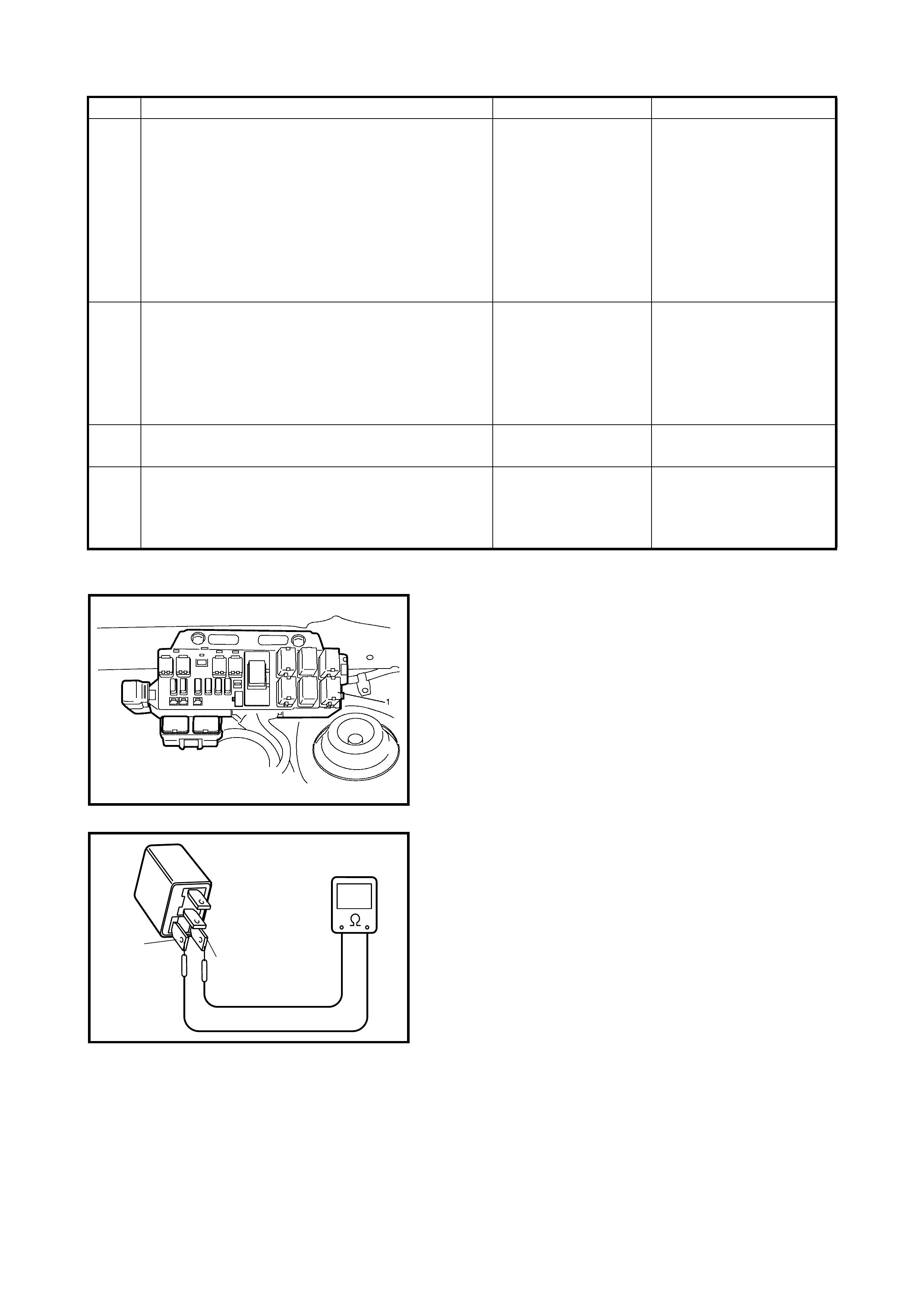
Fig. 1 for Step 2
Fig. 2 for Step 2
4 ECM Power Circuit Check.
1) Turn OFF ignition switch, disconnect
connectors from ECM and install main relay.
2) Check for proper connection to ECM at
terminals C41-11, C41-10, C41-5 and C41-6.
3) If OK, measure voltage between terminal
C41-11 and groun d, C41- 10 and groun d with
ignition switch ON.
Is each voltage 10 – 14 V?
Go to Step 5. BLK/WHT, BLK/YEL or
BRN/WHT circuit open.
5 ECM Power Circuit Check.
1) Using service wire, ground terminal C41-10
and measure voltage between terminal C41-5
and ground at ignition swi tc h ON.
Is it 10 – 14 V?
Check ground circuits
BRN/WHT and BLK/
YEL for open.
If OK, substitute a
known-good ECM
and rechec k.
Go to Step 6.
6 Is operating sound of main relay heard in Step 1? Go to Step 7. BLK/YEL or BLK/RED
wire open.
7 Main Relay Check.
1) Check main relay according to procedure in
Step 2.
Is main relay in good condition?
BLK/YEL or BLK/
RED wire open. Replace main relay.
Step Action Yes No
AB
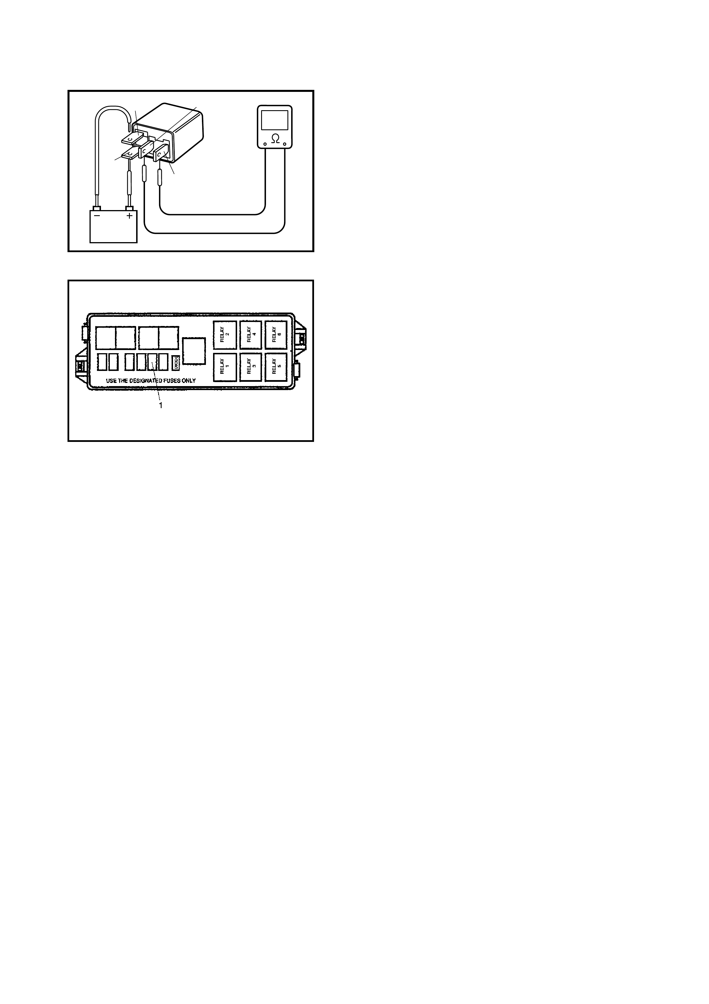
Fig. 3 for Step 2
Fig. 4 for Step 3
D
B
AC
2.13 DTC P0105 (DTC NO.11) MANIFOLD ABSOLUTE PRESSURE (M AP) CIRCUIT
MALFUNCTION & DTC P0106 (DTC NO.1 1) MANIFOLD ABSOLUTE PRESSURE (MAP)
RANGE / PE RFORMANCE PROBLEM
WIRING DIAGRAM / CIRCUIT DESCRIPTION
NOTE:
• When this DTC and DTC P0120 (No.13) are indicated together, it is possible that GRY/RED circuit is
open.
• When DTC P01 05 (No.11), P0 110 (No.18 ), P0115 (No.19 ) and P012 0 (No.13) are indicated toge ther, it is
possible that ORN circuit is open.
DTC CONFIRMATION PRO CEDURE
1. Clear DTC, start engine and keep it at idle for 1 min.
2. Check DTC using diagnosis connector No.1 or Tech 2.
ECM
GRY/RED
ORN
C42-22
5V
AMP
C42-26
5V
RED/WHT
C42-10
C42 (31P) C41 (24P) G02 (17P)
123456789
101112131415161718192021
222324252628 27293031
56
1234567
1112
9101113 12141516
1617
12
78
1314
34
910
15
1718 8
192021222324
DTC DETECTING CONDITION POSSIBLE CAUSE
• MAP s ensor signal is 0.19 V or lower
(Low pressure – High vacuum – Low voltage)
or
• MAP sensor signal is 4.5 V or higher
(High pressure – Low vacuum – High voltage)
• Variation of MAP sensor signal (manifold pres-
sure) is lower than specificatio n at cold start
• ORN circuit open
• GRY/RED circuit open or shorted to ground
• RED/WHT circuit op en or shorted to gr ound
• MAP sensor malfunction
• ECM malfunction
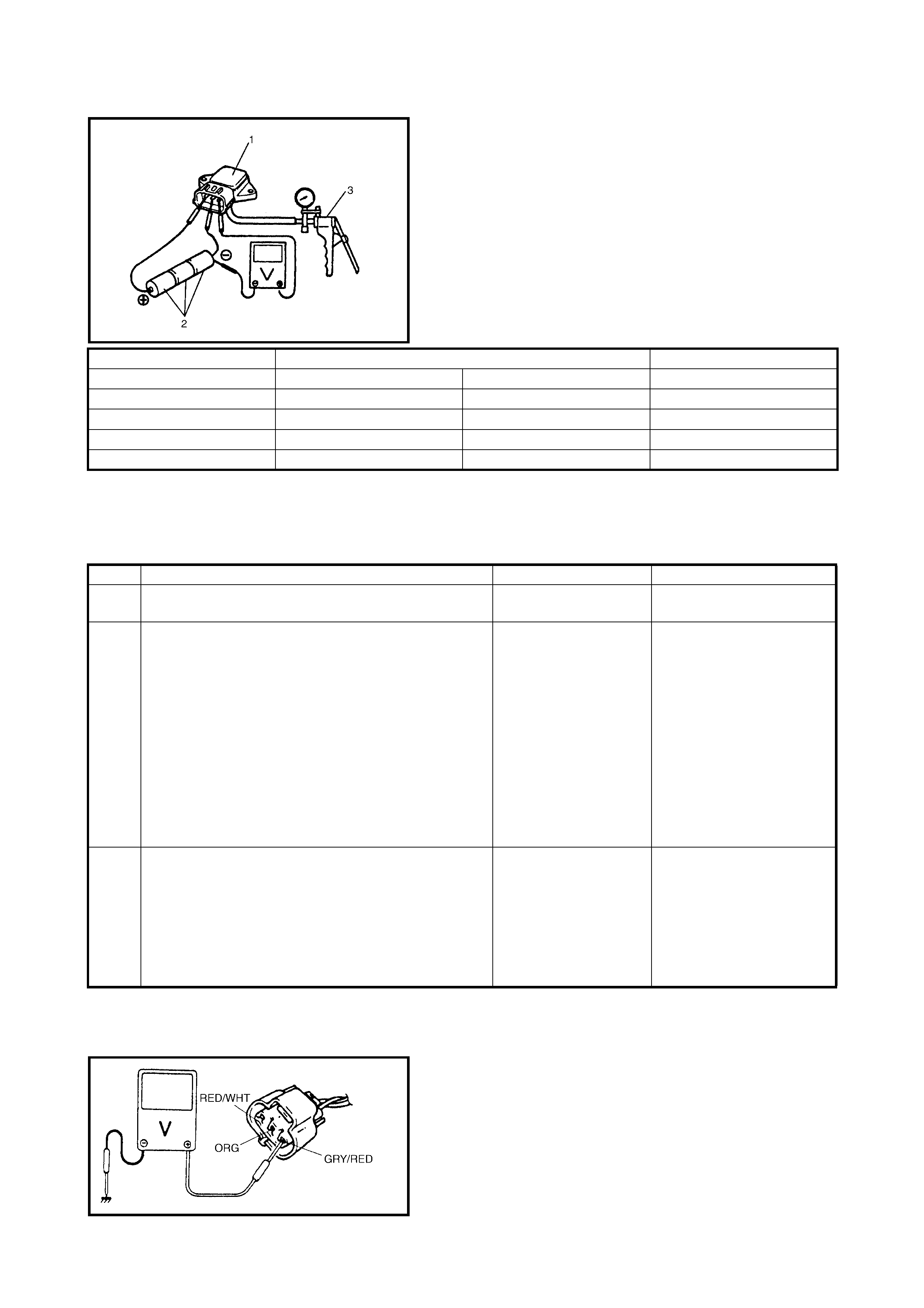
MAP SENSOR INDIVIDUAL CHECK
1. Disconnect connector from MAP sensor (1).
2. Remove MAP sensor.
3. Arrang e 3 new 1.5 V b atteries ( 2) in seri es (check th at
total voltage is 4.5 – 5.0 V) and connect its positive
terminal to V-in terminal of sensor and negative
terminal to Ground terminal. Then check voltage
between V-out and Ground.
Also, check i f v olta ge reduces when vacuum i s app lied
up to 400 mmHg by using vacuum pump (3).
Outp ut vo ltage (W he n inp u t vo l tage is 4 . 5 – 5. 5 V, am bi -
ent temp. 20 – 30°C)
If check result is not satisfactory, replace MAP sensor (1).
4. Install MAP sensor (1) securely.
5. Connect MAP sensor (1) connector securely.
INSPECTION
NOTE:
When battery voltage is applie d to GRY/RED wire, it is possible tha t MAP sensor is also fault y.
Fig. 1 for Step 3
ALTITUDE (Reference) BAROMETRIC PRESSURE OUTPUT VOLTAGE
(m) (mmHg) (kPa) (V)
0 – 610 760 – 707 100 – 94 3.3 – 4.3
611 – 1524 707 – 634 94 – 85 3.0 – 4.1
1525 – 2438 634 – 567 85 – 76 2.7 – 3.7
2439 – 3048 567 – 526 76 – 70 2.5 – 3.3
Step Action Yes No
1 Was ENGINE DIAG. FLOW TABLE performed? Go to Step 2. Go to 2.4 ENGINE DIAG.
FLOW TABLE.
2 Check Wire Harness.
1. Disconnect MAP sensor connector with ignition
switch OFF.
2. Check for proper connection of MAP sensor at
RED/WHT and GRY/RED wire terminals.
3. If OK, then with ignition switch ON, check voltage
between each of GRY/RED or RED/WHT wire
terminals and body ground. See Fig. 1.
Is voltage about 4 – 6 V at each terminal?
Go to Step 3. GRY/RED wire open or
shorted to ground circuit or
shorted to power
circuit (See NOTE), RED/
WHT wire open or shorted
to ground, poor C42-26 con-
nection or C42-22 connec-
tion.
If wire and connection are
OK, confirm that MAP sen-
sor is normal and th en sub-
stitute a known-good ECM
and recheck.
3 Check MAP sensor.
1. Chec k MAP sensor according to MAP Sensor
Individual Check mentioned previously.
Is it in good condition?
GRY/RED wire shorted
to ORN wire, RED/WHT
wire op en , poo r C42-1 0
connection.
If wire and connection
are OK, substitute a
known-good ECM and
recheck.
Replace MAP sensor .
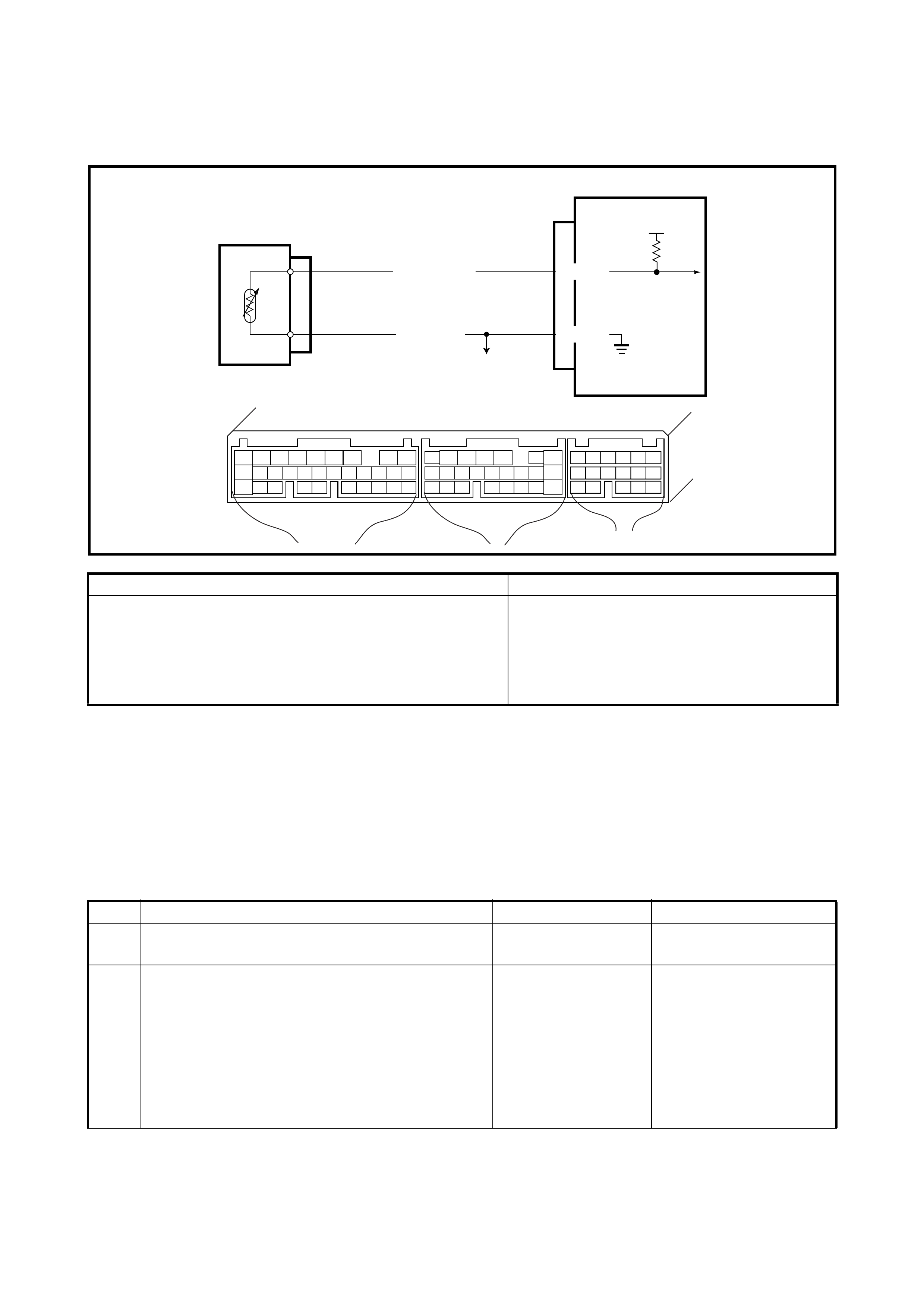
2.14 DTC P011 0 (DTC NO.18) INTAKE AIR TEMP. (IAT) CIRCUIT MALFUNCTION
WIRING DIAGRAM / CIRCUIT DESCRIPTION
NOTE:
• When DTC P01 05 (No.11), P0 110 (No.18 ), P0115 (No.19 ) and P012 0 (No.13) are indicated toge ther, it is
possible that ORN circuit is open.
• Before inspecting, be sure to check that ambient temperature is higher than – 40°C.
DTC CONFIRMATION PRO CEDURE
1. Clear DTC, start engine and keep it at idle for 1 min.
2. Check DTC using diagnosis connector No. 1 or Tech 2.
INSPECTION
C42-10
C42-15
5V
ECM
LT GRN/BLK
ORN
C42 (31P) C41 (24P) G02 (17P)
123456789
101112131415161718192021
222324252628 27293031
56
1234567
1112
9101113 12141516
1617
12
78
1314
34
910
15
1718 8
192021222324
DTC DETECTING CONDITION POSSIBLE CAUSE
• Low intake air temperature (High voltage-High resis-
tance)
or
• High intake air temperature (Low voltage-Low resis-
tance)
• LT GRN/BLK circuit op en or shor ted to
power.
• ORN circuit open
• IAT sensor malfunction
• ECM malfunction
Step Action Yes No
1 Was ENGINE DIAG. FLOW TABLE performed? Go to Step 2. Go to 2.4 ENGINE DIAG.
FLOW TABLE.
2 Check Wire Harness.
1. Disconnect IAT sensor connector with
ignition switch OFF.
2. Check for proper connection to IAT sensor at
LT GRN/BLK and ORN wire terminals.
3. If OK, then with ignition switch ON, is voltage
applied to LT GRN/BLK wire terminal about
4 – 6 V? See Fig. 1.
Go to Step 3. LT GRN/BLK wire open
or shorted to ground, or
poor C42-15 connection.
If wire and connection
are OK, substitute a
known-good ECM and
recheck.
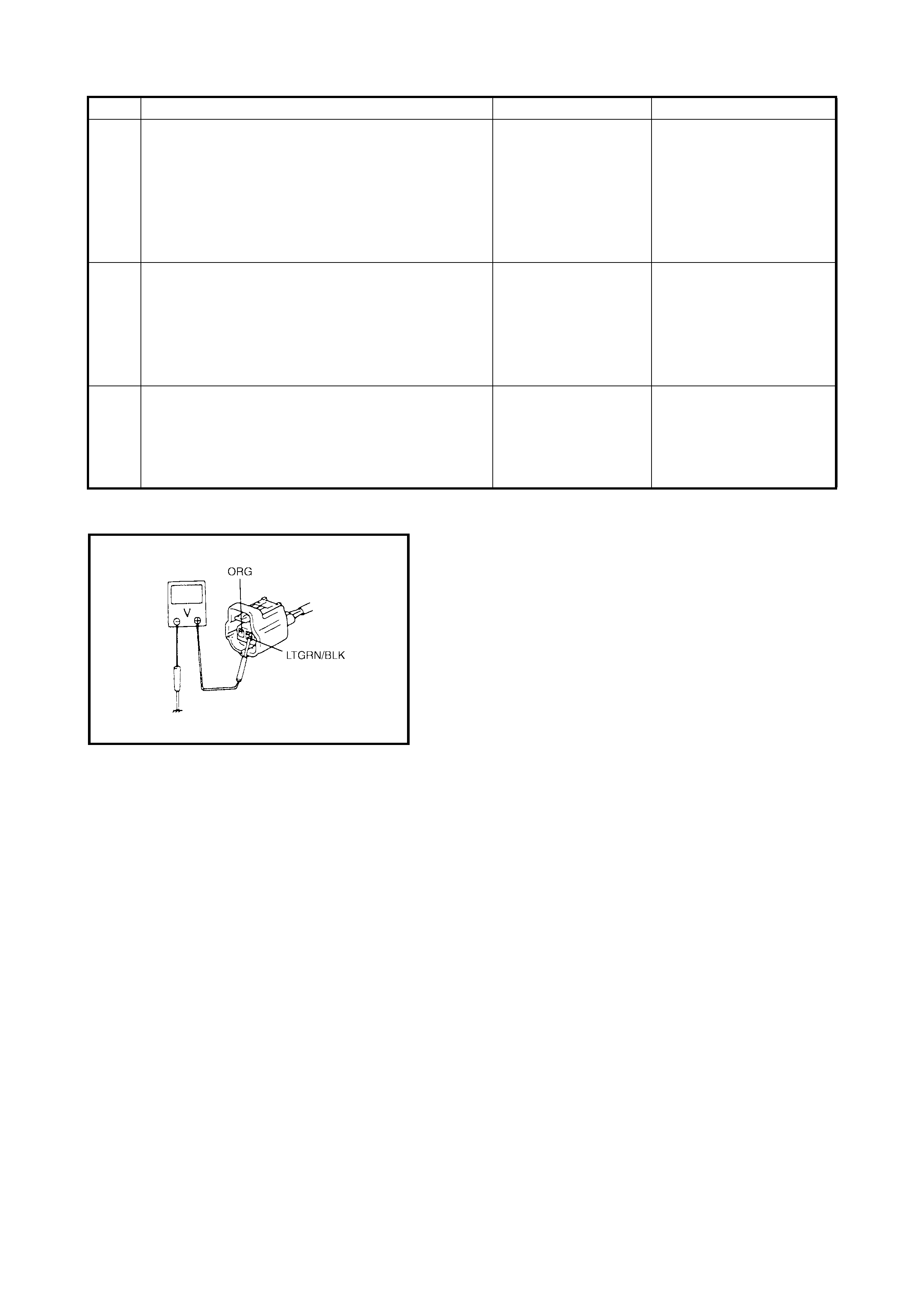
Fig. 1 for Step 2
3 Check Wire Harness.
1. Connect connector to IAT sensor.
2. Turn igniti on ON .
3. Measure voltage between ORN wire
terminal and engine body at IAT sensor
connector.
Is it 0 V?
Go to Step 4. ORN wire open or
shorted to power supply.
If wire is OK, substitute a
known good ECM and
recheck.
4 Check Wire Harness.
Turn ignition switch OFF.
Disconnect IAT sensor connector.
Measure resistance between ORN wire terminal
and engine body at IAT sensor connector.
Is it less than 1Ω
Go to Step 5. ORN wire open or
shorted to power supply.
If wire is OK, substitute a
known good ECM and
recheck.
5 Check IAT sensor, refer to Section 6E1
2.3 ELECTRONIC CONTROL SYSTEM - INTAKE
AIR TEMPERATURE SENSOR.
Is sensor OK?
Perform connection
of IAT and ECM con-
nector. If OK, substi-
tute a known good
ECM and recheck.
Replace IAT sensor.
Step Action Yes No
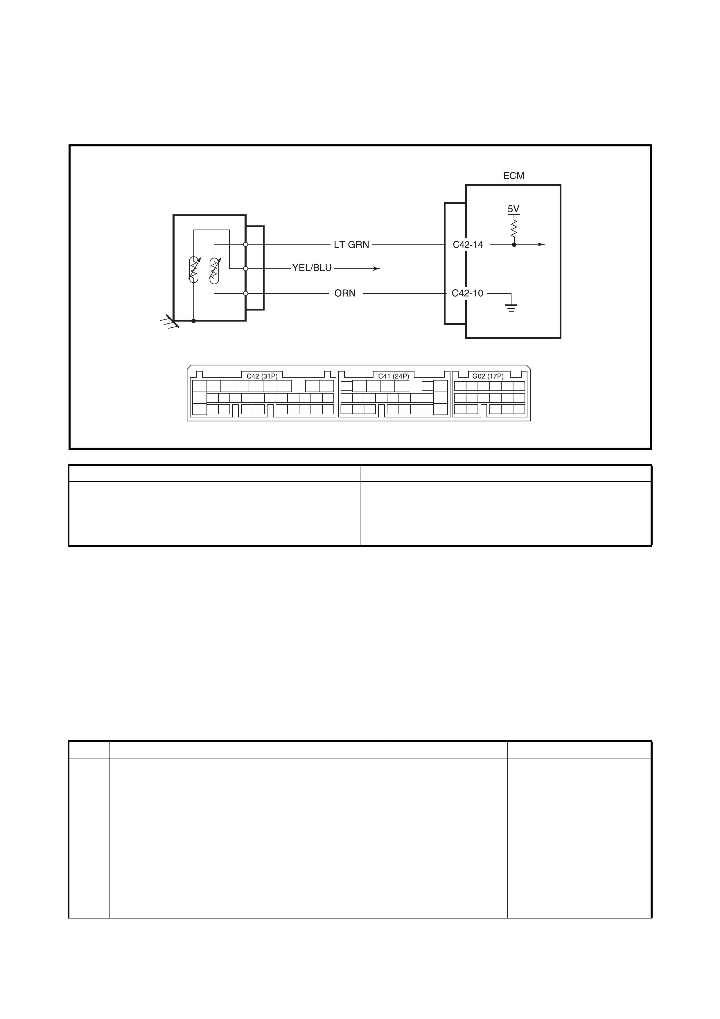
2.15 DTC P0115 (DTC NO.19) ENGINE COOLANT TEMPERATURE (ECT)
CIRCUIT MALFUNCTION
WIRING DIAGRAM / CIRCUIT DESCRIPTION
NOTE:
• Before inspecting, check that the coolant temp. meter in the combination meter indicates normal operating
temperature (Engine is not overheating).
• When DTC P01 05 (No.11), P0 110 (No.18 ), P0115 (No.19 ) and P012 0 (No.13) are indicated toge ther, it is
possible that ORN circuit open.
DTC CONFIRMATION PRO CEDURE
1) Clear DTC, start engine and keep it at idle for 1 min.
2) Check DTC using diagnosis connector No. 1 or Tech 2.
INSPECTION
DTC DETECTING CONDITION POSSIBLE CAUSE
• Low engine coolant temperature (High voltage-
High resistance) or,
• High engine coolant temperature (Low voltage-
Low resistance)
• LT GRN circuit open or shorted to power
• ORN circuit open
• ECT sens or malfun ct ion
• ECM malfunction
Step Action Yes No
1 Was ENGINE DIAG. FLOW TABLE performed? Go to Step 2. Go to 2.4 ENGINE DIAG.
FLOW TABLE.
2 Check Wire Harness.
1. Turn off ignition switch.
2. Disconnect ECT sensor connector.
3. Check for proper connection to ECT sensor
at LT GRN and ORN wire terminals.
4. If OK, then turn on ignition switch ON.
Is voltage applied to LT GRN wire terminal about
4 – 6 V? See Fig. 1.
Go to Step 3. LT GRN wire open or
shorted to ground, or
poor C42-14 connection.
If wire connection is OK,
substitute a known -good
ECM and recheck.

Fig. 1 for Step 2
Fig. 2 for Step 5
Fig. 3 for Step 6
3 Check Wire Harness.
1. Connect connector to ECT sensor.
2. Turn igniti on ON .
3. Measure voltage between ORN wire
terminal and engine body at ECT sensor
connector.
Is it 0 V?
Go to Step 4. ORN wire open or
shorted to power supply.
If wire is OK, substitute a
known good ECM and
recheck.
4 Check Wire Harness.
1. Turn igniti on ON .
2. Disconnect ECT sensor connector.
3. Measure resistance between ORN wire
terminal and engine body at ECT sensor
connector.
Is it less than 1 Ω?
Go to Step 5. ORN wire open or
shorted to power supply.
If wire is OK, substitute a
known-good ECM and
recheck.
5 Check ECT sensor, refer Section 6E1
2.3 ELECTRONIC CONTROL SYSTEMENGINE
COOLANT TEMPERATURE SENSOR.
Is sensor OK.
Perform connection
of ECT and ECM
connector . If OK, sub-
stitute a known good
ECM and recheck.
Replace ECT sensor.
Step Action Yes No
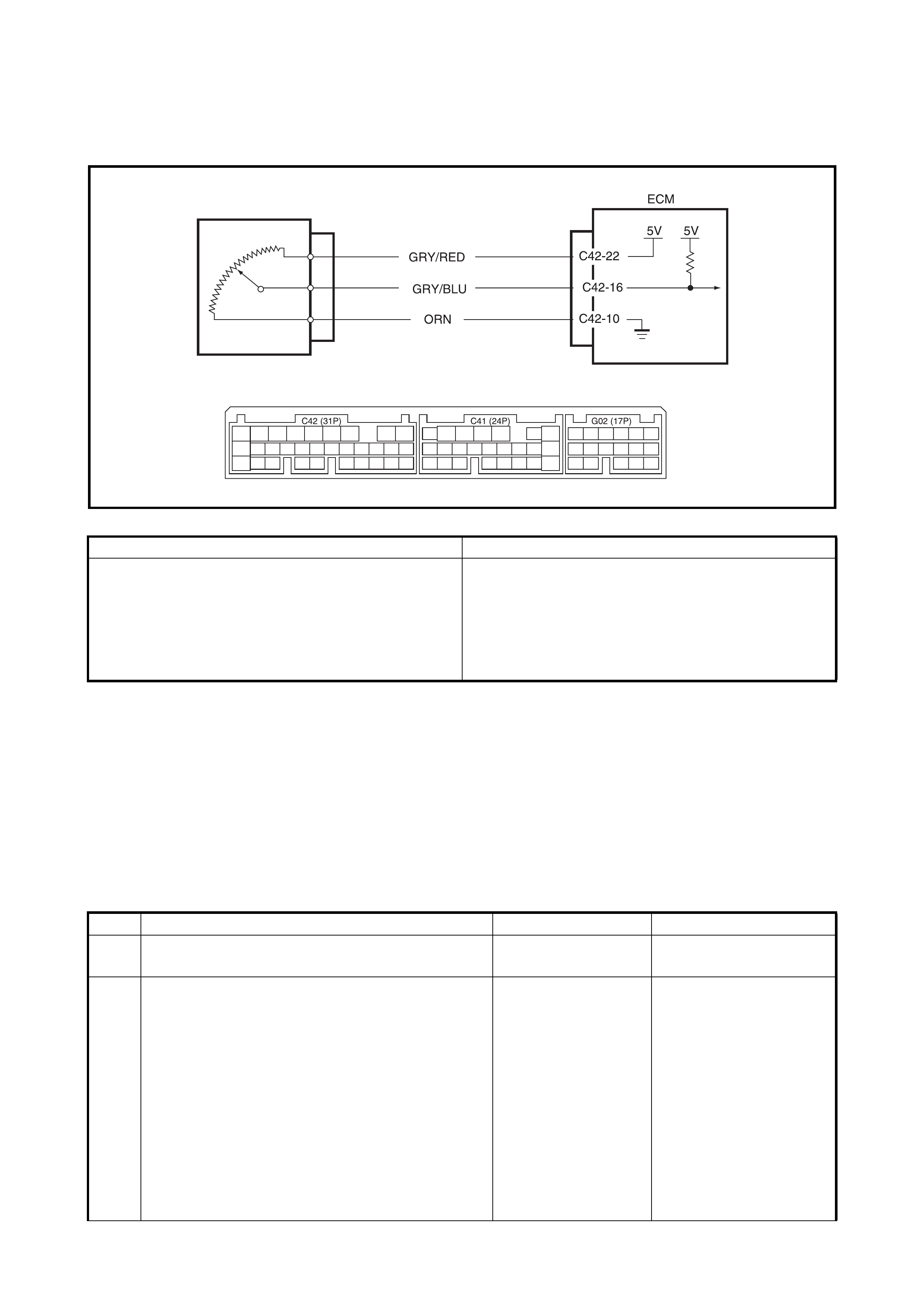
2.16 DTC P0120 (DTC NO.13) THROTTLE POSITION CIRCUIT MALFUNCTION
WIRING DIAGRAM / CIRCUIT DESCRIPTION
NOTE:
• When DTC P01 05 (No.11), P0 110 (No.18 ), P0115 (No.19 ) and P012 0 (No.13) are indicated toge ther, it is
possible that ORN or GRY/RED circuit is open.
• When this DTC and DTC P0105 (No.11) are indicated together, it is possible that GRY/RED circuit is
open.
DTC CONFIRMATION PRO CEDURE
1. Clear DTC, start engine and keep it at idle for 1 min.
2. Check DTC using diagnosis connector No. 1 or Tech 2.
INSPECTION
DTC DETECTING CONDITION POSSIBLE CAUSE
• Sign al vo ltage high
or
• Sign al vo ltag e low
• ORN circuit open
• GRY/BLU circuit open or shorted to ground
• GRY/RED circuit open or shorted to power or
ground
• TP sensor malfunction
• ECM malfunction
Step Action
YES
No
1 Was ENGINE DIAG. FLOW TABLE performed? Go to Step 2. Go to ENGINE DIAG.
FLOW TABLE.
2 Check Wire Harness.
1. Disconnect connector from TP sensor with
ignition switch OFF.
2. Check for proper connection to TP sensor at
GRY/RED, GRY/BLU and ORN wire
terminal.
3. If OK, then with ignition switch ON, check
voltage between each of GRY/RED or GRY/
BLU wire terminals and body ground. See
Fig. 1.
Is voltage about 4 – 6 V at each terminal?
Go to Step 4. GRY/RED wire open,
GRY/RED wire shorted to
ground circuit or power
circuit or GRY/BLU wire,
ORN wire open or
shorted to ground circuit
or poor C42-22 or C42-
16 connection.
If wire and connection
are OK, substitute a
known-good ECM and
recheck.
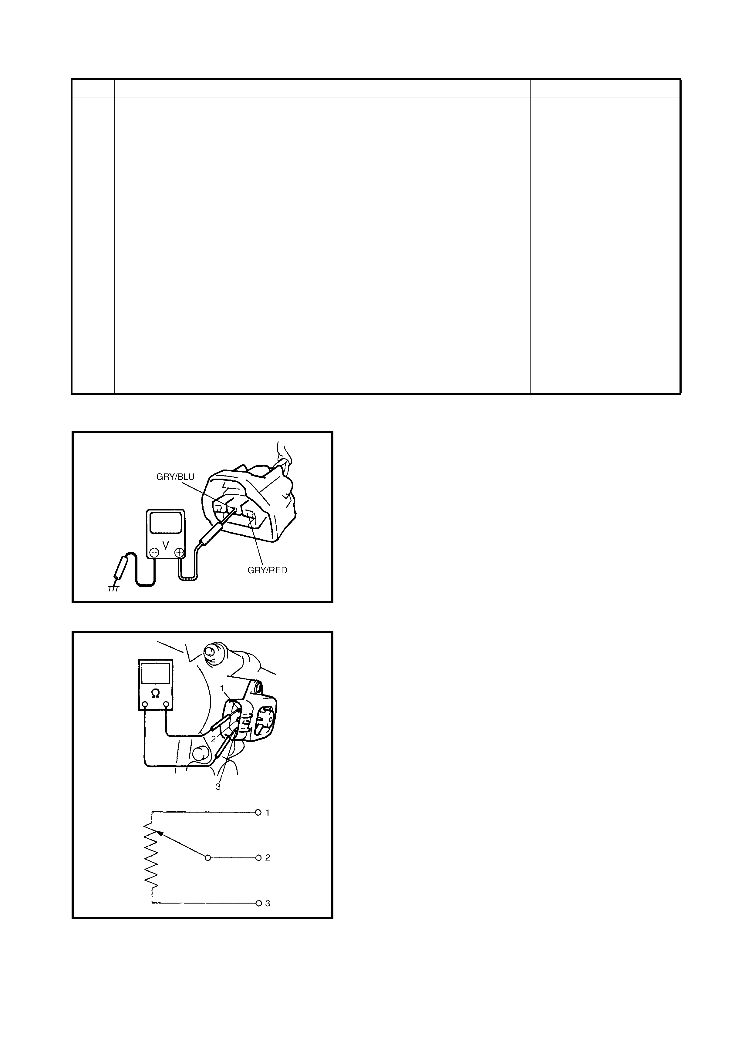
Fig. 1 for Step 2
Fig. 2 for Step 3
3
Check TP Sensor.
1. Check resistance between terminals of TP
sensor. See Fig. 2.
Between 1 and 2: 2.5 – 6.0 kΩ
Between 1 and 3: 100 Ω – 20 kΩ
varying according to throttle valve opening
Are mea s ured values within specifications?
Intermittent trouble.
Check for intermit-
tent, refer to
1.7 ELECTRICAL
CIRCUIT
INSPECTION
PROCEDURE -
INTERMITTENT
AND POOR
CONNECTION in
Section 0A.
ORN wire open or
poor C42-10
connection.
If wire and connec-
tion are OK, substi-
tute a known-good
ECM and recheck.
Replace TP sensor.
Step Action
YES
No
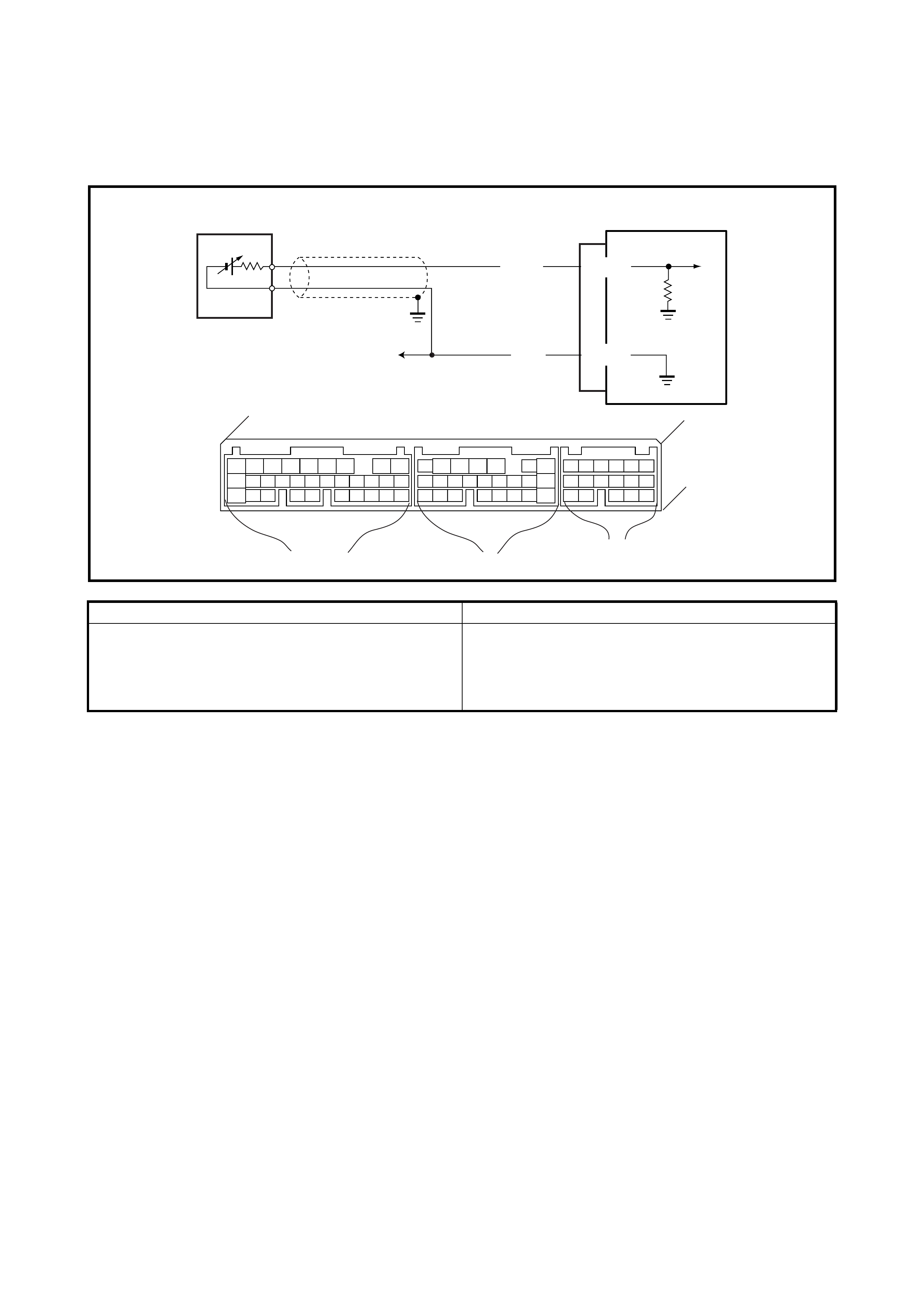
2.17 DTC P0130 (DTC NO.14) HEATED OXYGEN SENSOR (HO2S)
CIRCUIT MALFUNCTION
WIRING DIAGRAM / CIRCUIT DESCRIPTION
DTC CONFIRMATION PRO CEDURE
WARNING:
• When performing a road test, select a place whe re there is no traffic or possibility of an accident.
Take care during testing.
• Road test should be carried out with 2 persons, a driver and a tester.
1. Turn ignition OFF. Clear DTC with ignition switch ON, check vehicle and environmental condition for:
•Altitude (barometric pressure) : 2400 m, 8000 ft or less (560 mmHg, 75 kPa or more)
•Ambient temp.: –10°C or higher
•Intake air temp.: 70°C or lower
2. Warm up engine to normal operating temperature.
3. Drive vehicle at 50 – 60 km /h for 2 min.
4. Stop vehicle and run engine at idle for 2 min.
5. Repeat Steps 2 – 4.
6. Check DTC using diagnosis connector No.1 or Tech 2.
ECM
WHT
ORN C42-10
C42-13
E11
C42 (31P) C41 (24P) G02 (17P)
123456789
101112131415161718192021
222324252628 27293031
56
1234567
1112
9101113 12141516
1617
12
78
1314
34
910
15
1718 8
192021222324
DTC DETECTING CONDITION POSSIBLE CAUSE
• When running at idle speed after engine
warmed up and running at specified vehicle
spee d, HO2S output voltage does not go below
0.3 V or over 0.6 V.
• Heated oxygen sensor malfunction
• WHT or ORN circuit open (poor connection) or
short
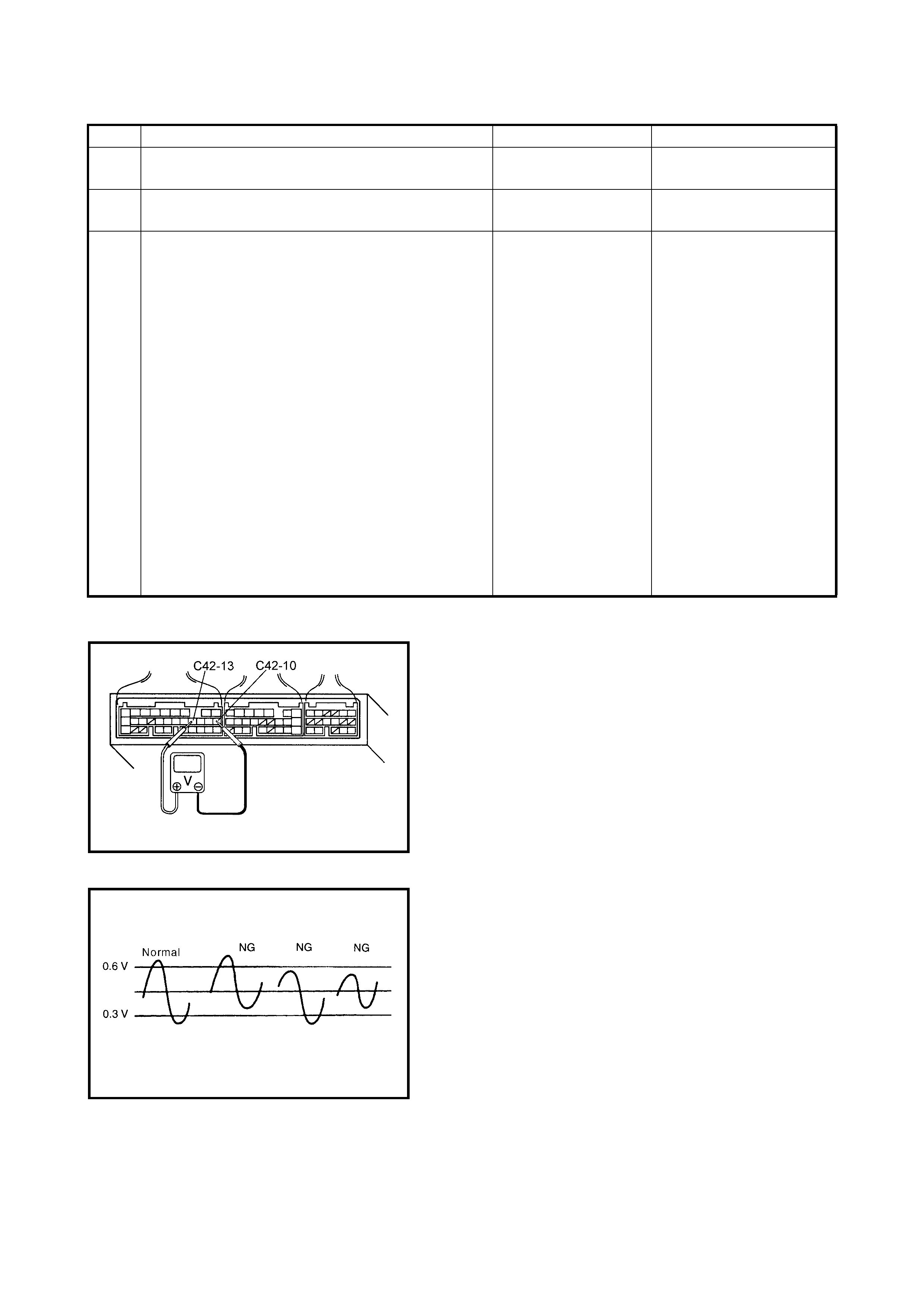
INSPECTION
Fig. 1 for Step 3
Fig. 2 for Step 3
Step Action Yes No
1 Was ENGINE DIAG. FLOW TABLE performed? Go to Step 2. Go to 2.4 ENGINE DIAG.
FLOW TABLE.
2 Is there DTC(s) other than HO2S (DTC P0130)? Go to applicable DTC
Diag. Table. Go to Step 3.
3 Check HO2S signal.
1. Warm up engine to normal operating
temperature and keep it at 2000 r/min. for 60
sec.
2. Repeat racing engine (Repeat depressing
accelerator pedal 5 to 6 times continuously
and take foot off from pedal to richen and lean
the A/F mixture).
3. Check voltage between terminal C50-13 and
terminal C50-10 in the connector connected
to the ECM. See Fig. 1 and 2.
Does HO2S output voltage deflect between 0.2 V
and over 0.45 V repeatedly?
Intermittent trouble.
Check for intermit-
tent, refer to
1.7 ELECTRICAL
CIRCUIT
INSPECTION
PROCEDURE -
INTERMITTENT
AND POOR
CONNECTION in
Section 0A.
If checks are OK, go
to DTC P0135 (DTC
No. 14) HEATED
OXYGEN SENSOR
(HO2S) HEATER
CIRCUIT
MALFUNCTION.
Check WHT and ORN
wires for open and short,
and connections for poor
connection.
If wires and connections
are OK, go to DTC P0135
(DTC No. 14) HEATED
OXYG EN SENSOR
(HO2S) HEATER CIR-
CUIT MALFUNCTION.
If checks are OK, replace
HO2 sensor.
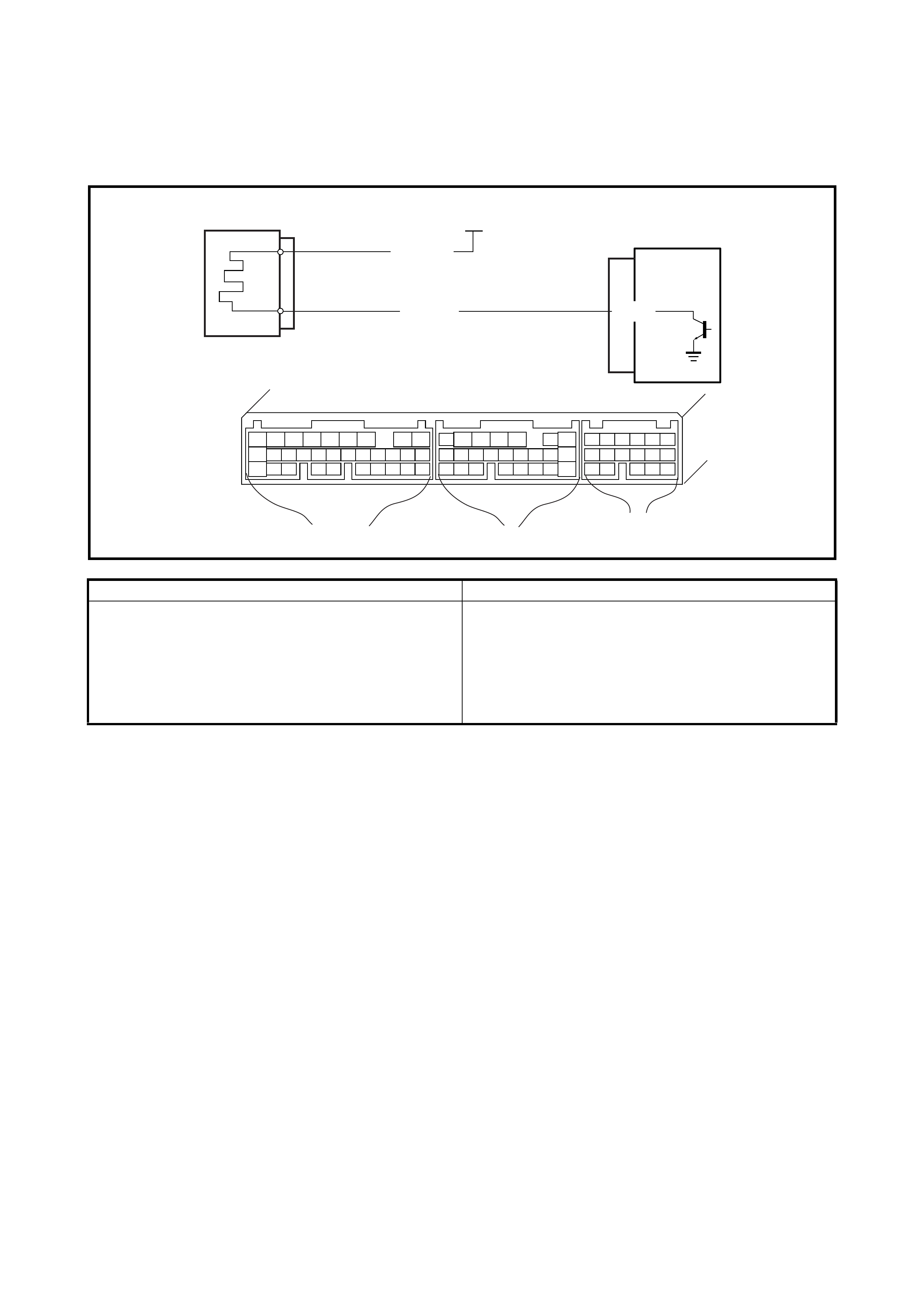
2.18 DTC P0135 (DTC NO.14) HEATED OXYGEN SENSOR (HO2S)
HEATER CIRCUIT MALFUNCTION
WIRING DIAGRAM / CIRCUIT DESCRIPTION
DTC CONFIRMATION PRO CEDURE
WARNING:
• When performing a road test, select a place whe re there is no traffic or possibility of an accident.
Take care during testing.
• Road test should be carried out with 2 persons, a driver and a tester.
1. Turn ignition switch OFF.
2. Clear DTC with ignition switch ON, start engine and keep it at idle for 1 min.
3. Start vehicle and depress accelerator pedal fully for 5 sec. or longer.
4. Stop vehicle.
5. Repeat Steps 3 – 4.
6. Check DTC using diagnosis connector No. 1 or Tech 2.
ECM
BLK/WHT
RED/BLU C42-7
IG1
C42 (31P) C41 (24P) G02 (17P)
123456789
101112131415161718192021
222324252628 27293031
56
1234567
1112
9101113 12141516
1617
12
78
1314
34
910
15
1718 8
192021222324
DTC DETECTING CONDITION POSSIBLE CAUSE
DTC will set when one of the following conditions is
met:
• Low voltage at terminal C42-7 when engine is
running at high load.
• High voltage at terminal C42-7 when engine is
running under condition other than above.
• HO2S heater circuit open or shorted to ground
• ECM malfunction
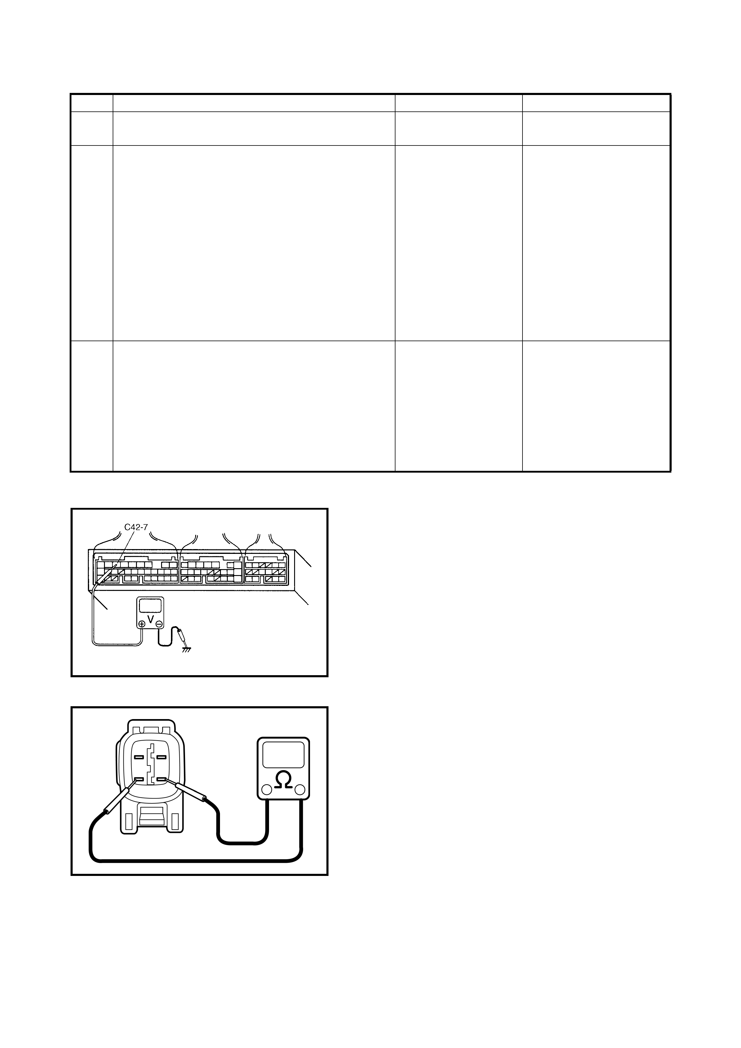
INSPECTION
Fig. 1 for Step 2
Fig. 2 for Step 3
Step Action Yes No
1 Was ENGINE DIAG. FLOW TABLE performed? Go to Step 2. Go to 2.4 ENGINE DIAG.
FLOW TABLE.
2 Check Heater for operation.
1. Check voltage at terminal C42-7. See Fig. 1.
2. Warm up engine to normal operating temper-
ature.
3. Stop engine.
4. Turn ignition switch ON and check voltage at
terminal C42-7. See Fig. 1. V oltage should be
over 10 V.
5. S tart engine, run it at idle and check voltage at
the same terminal. Voltage should be below
1.9 V.
Are check results are speci fied?
Intermittent trouble.
Check for intermit-
tent, refer to
1.7 ELECTRICAL
CIRCUIT
INSPECTION
PROCEDURE -
INTERMITTENT
AND POOR
CONNECTION in
Section 0A.
Go to Step 3.
3 Check Heater of Sensor.
1. Disconnect HO2S coupler with ignition
switch OFF.
2. Check for proper connection to HO2S at BLK/
WHT and RED/BLU wire terminals.
3. If OK, then check heater resistance. See Fig.
2.
Is it 5.0 – 6 .4 Ω at 20°C?
RED/BLU wire open
or shorted to ground
or poor connection at
C42-7. If wire and
connection are OK,
substitute a known-
good ECM and
recheck.
Replace HO2S.
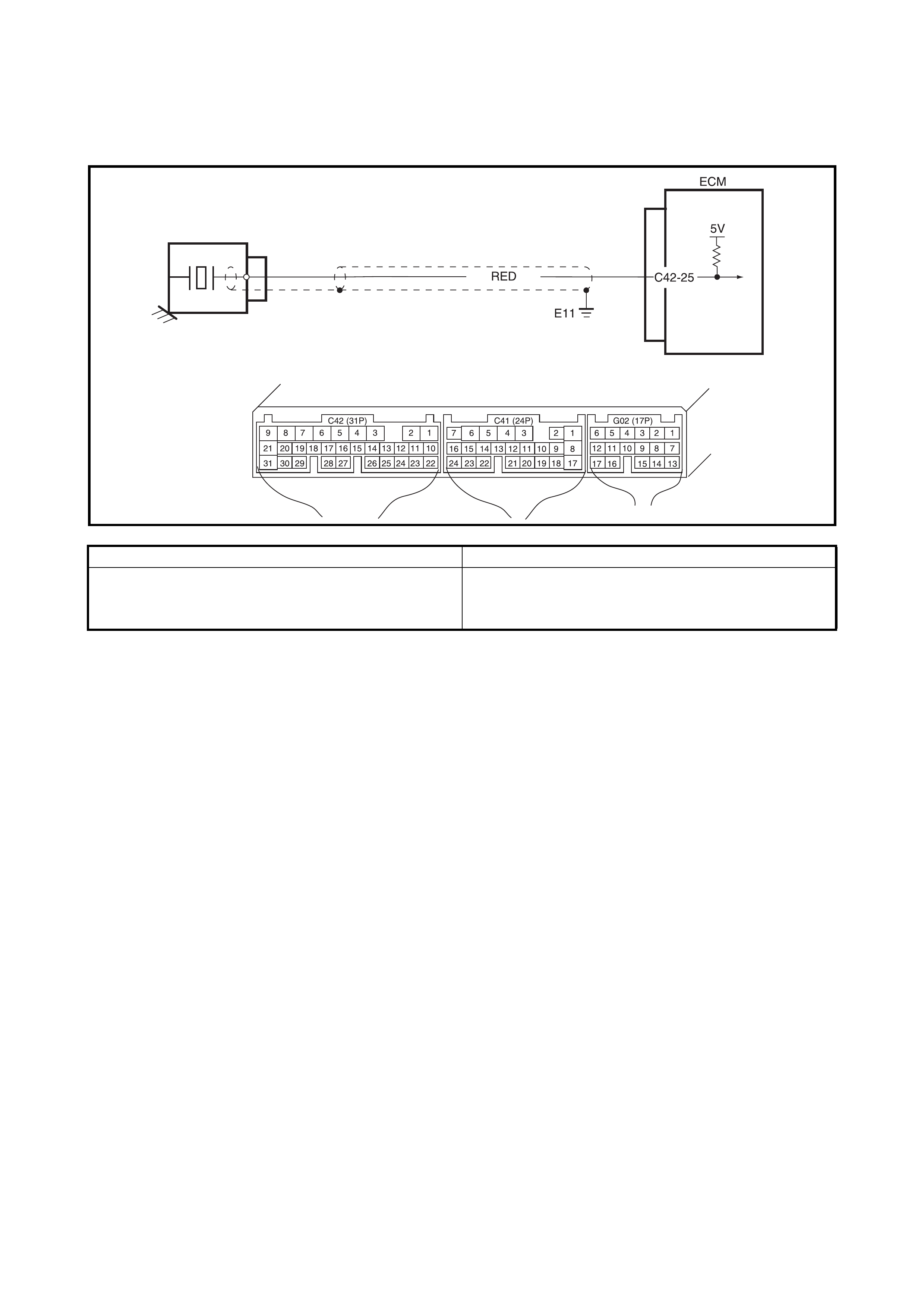
2.19 DTC P0325 (DTC NO.17) KNOCK SENSOR CIRCUIT MALFUNCTION
WIRING DIAGRAM / CIRCUIT DESCRIPTION
DTC CONFIRMATION PRO CEDURE
1. Clear DTC, start engine and keep it at idle for 1 min.
2. Check DTC using diagnosis connector No. 1 or Tech 2.
DTC DETECTING CONDITION POSSIBLE CAUSE
• Knock sensor voltage is 3.91 V or more
or
• Knock sensor voltage is 1.23 V or less
• RED circuit open or shorted to ground
• Knock sensor malfunction
• ECM malfunction
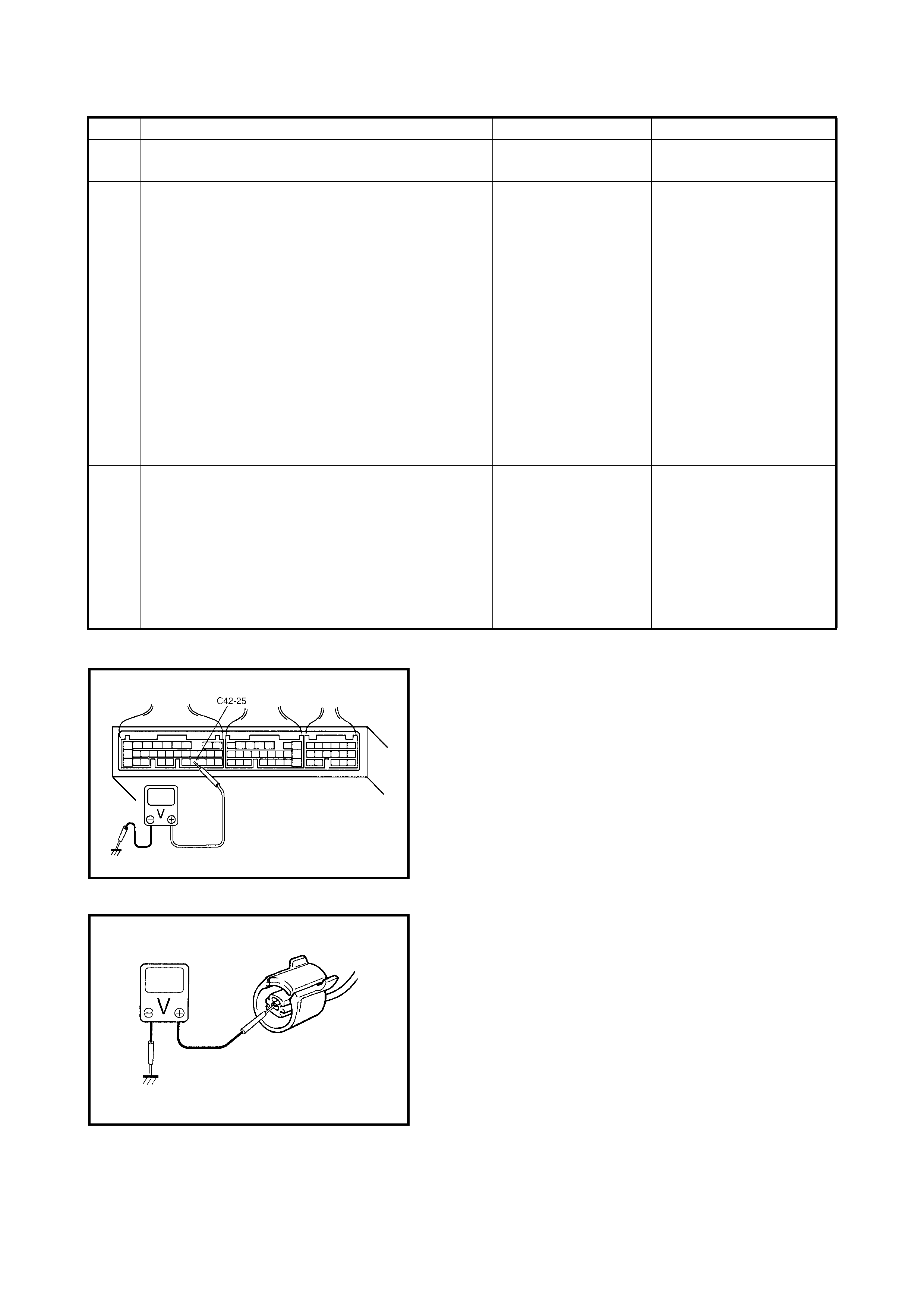
INSPECTION
Fig. 1 for Step 2
Fig. 2 for Step 2
Step Action Yes No
1 Was ENGINE DIAG. FLOW TABLE performed? Go to Step 2. Go to 2.4 ENGINE DIAG.
FLOW TABLE.
2 Check Kn ock Sensor Si gna l.
1. With engine running, check voltage from
C42-25 terminal of ECM connector to body
ground. See Fig. 1.
Is voltage about 1.23 – 3.91 V?
Knock sensor and its
circuit are in good
condition.
Intermittent trouble or
faulty ECM.
Recheck, refer to
1.7 ELECTRICAL
CIRCUIT
INSPECTION
PROCEDURE -
INTERMITTENT
AND POOR
CONNECTIONin
Section 0A.
Go to Step 3.
3 Check Kn ock Sensor Ou tput .
1. Stop engine.
2. With ignition switch at OFF position,
disconnect knock sensor connector.
3. With ignition switch at ON position, check
voltage from RED terminal of knock sensor
connector to body ground. See Fig. 2.
Is it 4 – 5 V?
Faulty knock sensor.
Substitute a known-
good knock sensor
and rechec k.
RED wire open, shorted
to ground circuit or poor
C42-25 connection.
If wire and connection
are OK, substitute a
known-good ECM and
recheck.
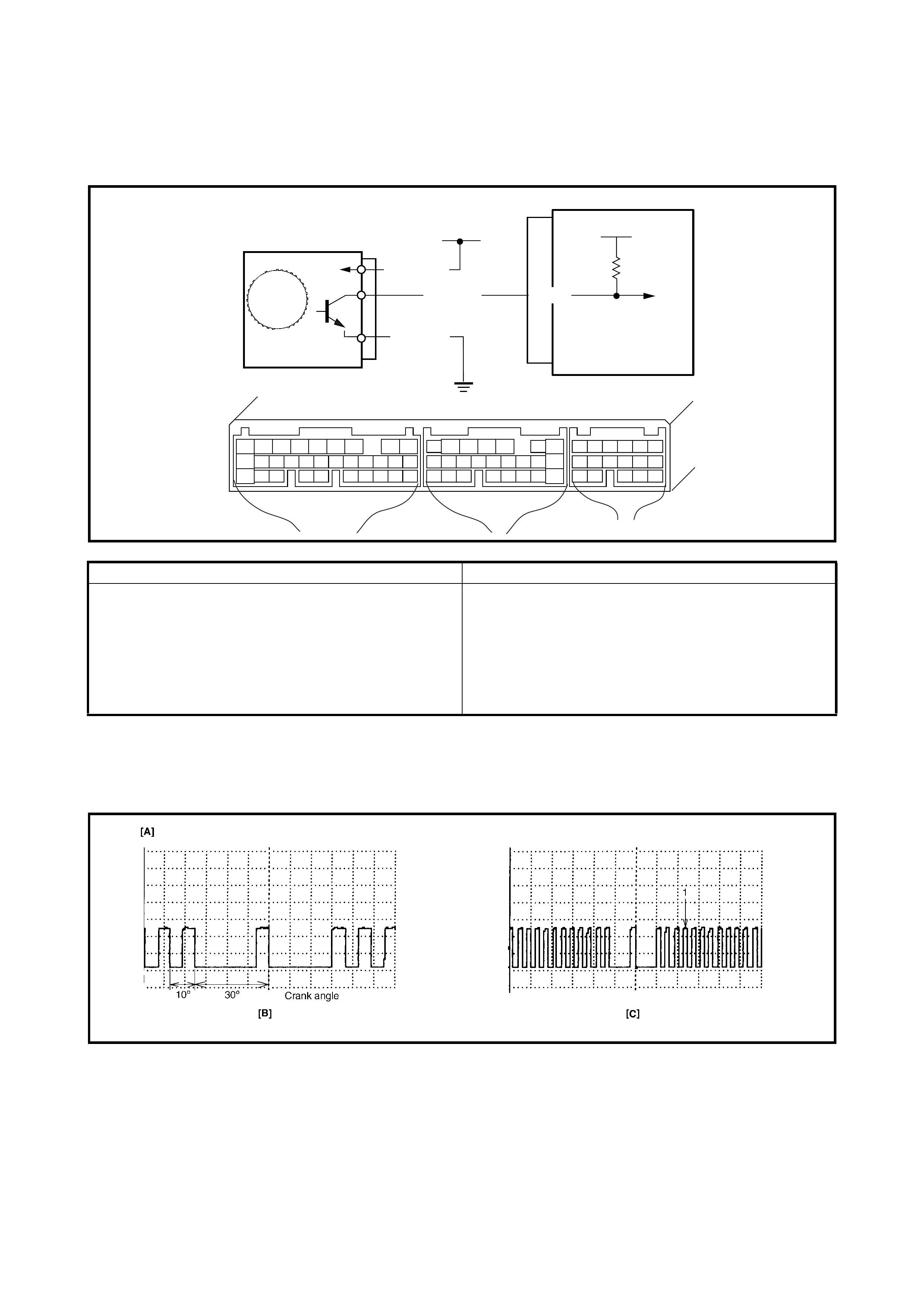
2.20 DTC P0335 (DTC NO.23) CRANKSHAFT POSITION (CKP)
SENSOR CIRCUIT MALFUNCTION
WIRING DIAGRAM / CIRCUIT DESCRIPTION
REFERENCE
Connect oscilloscope between terminals C42-23 of ECM connect to while connected to the ECM and to
ground and check CKP sensor signal.
Legend
DTC CONFIRMATION PRO CEDURE
1. Clear DTC and crank engine for 2 sec.
2. Check DTC using diagnosis No. 1 connector or Tech 2.
ECM
5V
+B
BLK/RED
YEL/BLK
C42-23
BLK/ORN
C42 (31P) C41 (24P) G02 (17P)
123456789
101112131415161718192021
222324252628 27293031
56
1234567
1112
9101113 12141516
1617
12
78
1314
34
910
15
1718 8
192021222324
DTC DETECTING CONDITION POSSIBLE CAUSE
• No CKP sensor signal for 2 seconds at engine
cranking.
• No engine start signal with engine cranking.
• CKP sensor circuit open or short.
• Cranks ha ft timi ng ch ai n pu l le y te et h da m ag e d.
• CKP sensor malfunct ion, foreign material being
attached or improper installation.
• ECM malfunction.
• Engine start s ignal circuit malfunction.
1. BTDC 5° (Crank angle) [B] : Waveforms at specified idle speed
[A] : Oscilloscope Waveforms [C] : Waveforms at 2000 r/min

INSPECTION
Step Action Yes No
1 Was ENGINE DIAG. FLOW TABLE performed? Go to Step 2. Go to 2.4 ENGINE DIAG.
FLOW TABLE.
2 Check CKP Sensor and Connector for proper
installation.
Is CKP sensor installed properly and connector
connected securely?
Go to Step 3. Rectify and recheck.
3 Check Wire Harness and Connection.
1. Disconnect connector from CKP sensor.
2. Check for proper connection to CKP sensor
at each terminal.
3. If OK, turn ignition switch ON and check for
voltage at each terminal of the disconnected
sensor connector. See Fig. 1.
Terminal B+: 10 – 14 V
Terminal Vout: 4 – 5 V
Terminal GND: – 0 V
Is check result satisfactory?
Go to Step 5. Go to Step 4.
4 Was terminal V out voltage out of specification in
Step 3 check? YEL/BLK wire open,
short or poor connec-
tion.
If wire and connec-
tion are OK, substi-
tute a known-good
ECM and recheck.
BLK/RED or BLK/ORN
wire open, short or poor
connection.
5 Check Ground Circuit for open.
1. Turn ignition swi tc h OFF.
2. Check for continuity between GND terminal
of CKP sensor connector and engine
ground.
Is continui ty ind ic ate d?
Go to S tep 6. BLK/ORN wire open or
poor ground connection.
6 Check engine start signal.
1. Check voltage at terminal C41-20 of
connector while connected to the ECM and
to engine ground with engine cranking.
Is the voltage more than 6 V?
Go to Step 7. BLK/YEL circuit open or
short to ground.
If wire is OK, check
starter motor, refer to
Section 6G, CRANKING
SYSTEM.
7 Check CKP Sensor for operation.
1. Remove CKP sensor from cylinder block.
2. Remove metal particles on end face of CKP
sensor, if any.
3. Connect each connector to ECM and CKP
sensor.
4. Turn ignition swi tc h ON.
5. Check for voltage at terminal C42-23 of
connector while connected to the ECM by
passing a magnetic substance (iron) while
keeping approximately 1 mm gap with respect
to end face of CKP sensor. See Fig. 2 and 3.
Does voltage vary from low (0 –1 V) to high (4 – 5
V) or from high to low?
Go to Step 8. Replace CKP sensor.
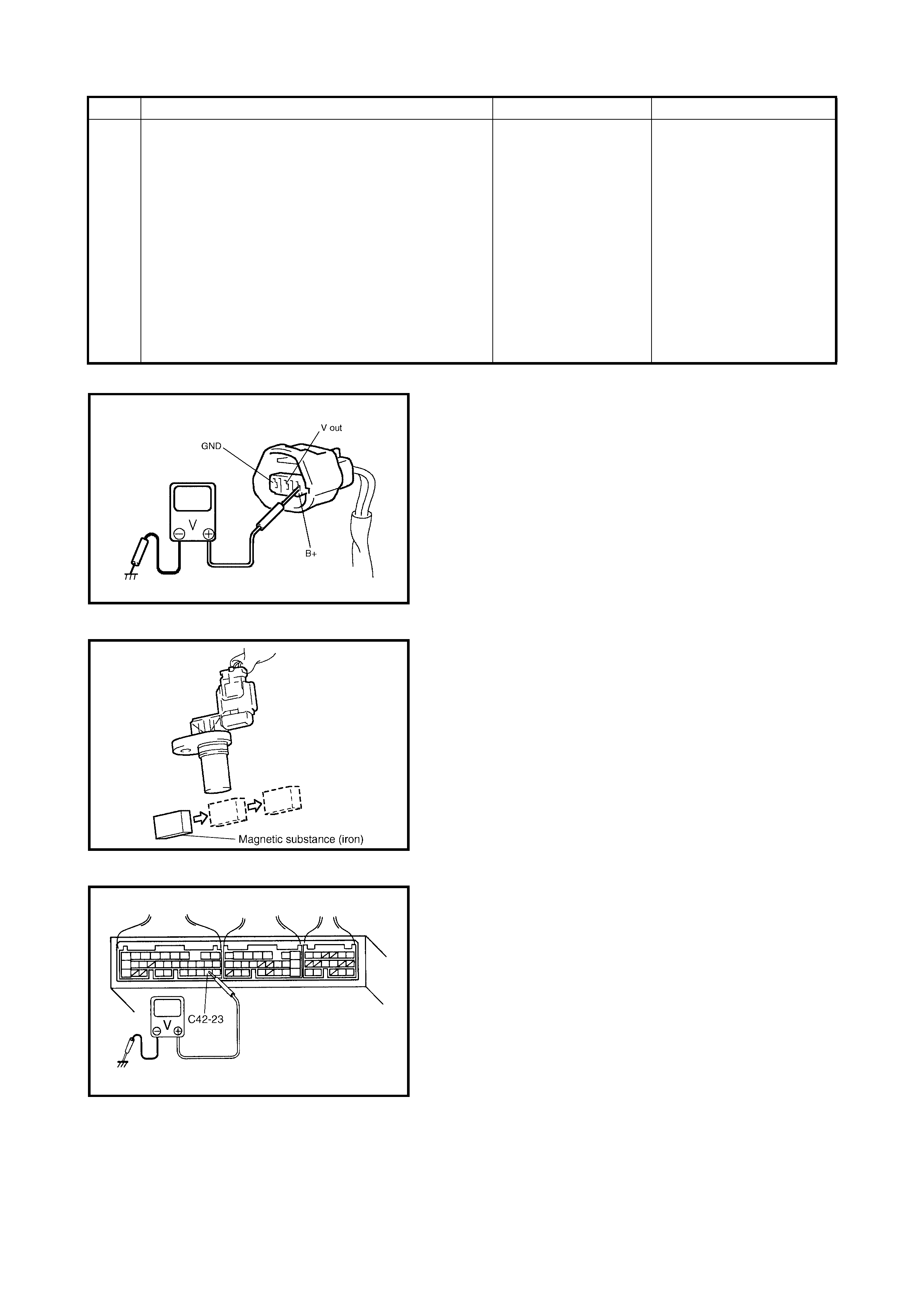
Fig. 1 for Step 3
Fig. 2 for Step 7
Fig. 3 for Step 7
Fig. 4 for Step 8
8 Check Signal Rotor for the following. See Fig. 4.
•Damage
• No foreign material attached
Is it in good condition?
Intermittent trouble or
faulty ECM.
Check for intermit-
tent, refer to
1.7 ELECTRICAL
CIRCUIT
INSPECTION
PROCEDURE -
INTERMITTENT
AND POOR
CONNECTIONin
Section 0A.
Clean rotor teeth or
replace CMP sensor.
Step Action Yes No
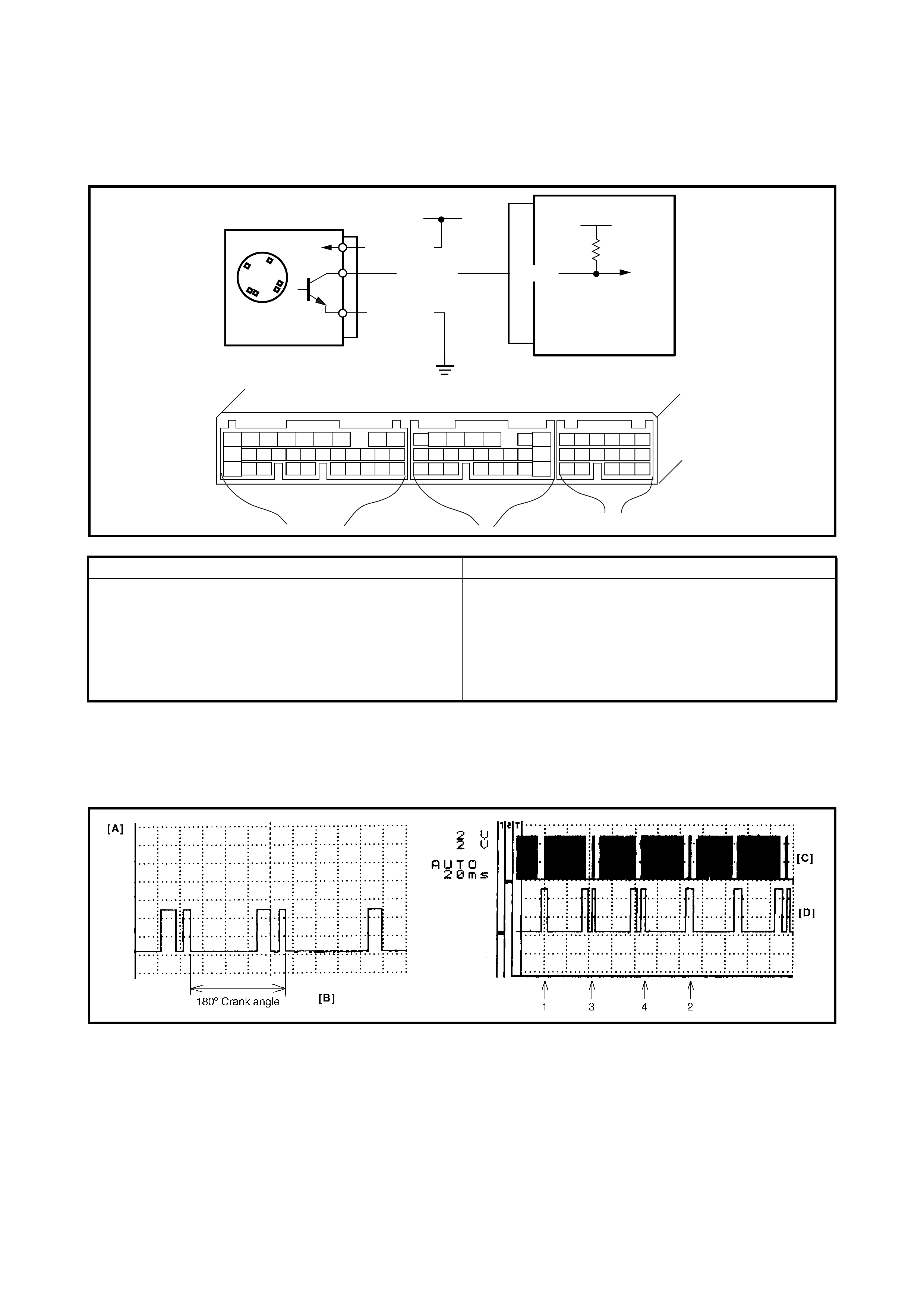
2.21 DTC P0340 (DTC NO.15) CA MSHAFT POSITION (CMP)
SENSOR CIRCUIT MALFUNCTION
WIRING DIAGRAM / CIRCUIT DESCRIPTION
REFERENCE
Connect oscilloscope between terminals C42-11 of the ECM connector while connected to the ECM and body
ground and check CMP sensor signal. When CKP circuit is failed (open or short), the ECM will identify the cyl-
inders only by CMP sensor signal.
Legend
DTC CONFIRMATION PRO CEDURE
1) Clear DTC.
2) Start engine and keep it at idle for 1 min.
3) Check DTC using diagnosis connector No. 1 or Tech 2.
ECM
5V
+B
BLK/RED
RED/YEL
BLK/ORN
C42 (31P) C41 (24P) G02 (17P)
123456789
101112131415161718192021
222324252628 27293031
56
1234567
1112
9101113 12141516
1617
12
78
1314
34
910
15
1718 8
192021222324
C42-11
DTC DETECTING CONDITION POSSIBLE CAUSE
• No CMP sensor signal during engine running
(CKP sensor signal is inputted).
• Mismatch input signal compared to crankshaft
position signal.
• CMP sensor circuit open or short.
• S ignal rotor teeth dam aged.
• CMP sensor malfunction, foreign material being
attached or improper installation.
• Incorrect starter signal.
• ECM malfunction.
1. No.1 cylinder 3. No.3 cylinder [A]: Oscilloscope Waveforms [C]: CKP sensor signal
2. No.2 cylinder 4. No.4 cylinder [B]: Waveforms at specified
idle speed [D]: CMP senso r signa l

INSPECTION
Step Action Yes No
1 Was ENGINE DIAG. FLOW TABLE performed? Go to Step 2. Go to 2.4 ENGINE DIAG.
FLOW TABLE.
2 Check CMP Sensor and connector for proper
installation.
Is CMP sensor installed properly and connector
connected securely?
Go to Step 3. Rectify and recheck.
3 Check Wire Harness and Connection.
1. Disconnect connector from CMP sensor.
2. Check for proper connection to CMP sensor
at each terminal.
3. If OK, turn ignition switch ON and check for
voltage at each terminal of sensor connector
disconne cte d. See F ig. 1.
Terminal B+: 10 – 14 V
Terminal V-out: 4 – 5 V
Terminal GND: 0 V
Is check result satisfactory?
Go to Step 5. Go to Step 4.
4 Was terminal V-out voltage out of specification in
Step 3 check? RED/YEL wire open,
short or poor connec-
tion.
If wire and connec-
tion are OK, substi-
tute a known-good
ECM and recheck.
BLK/RED or BLK/ORN
wire open, short or poor
connection.
5 Check Ground Circuit for Open.
1. Turn ignition swi tc h OFF.
2. Check for continuity between GND terminal
of CMP sensor connector and engine
ground.
Is continui ty ind ic ate d?
Go to S tep 6. BLK/ORN wire open or
poor ground connection.
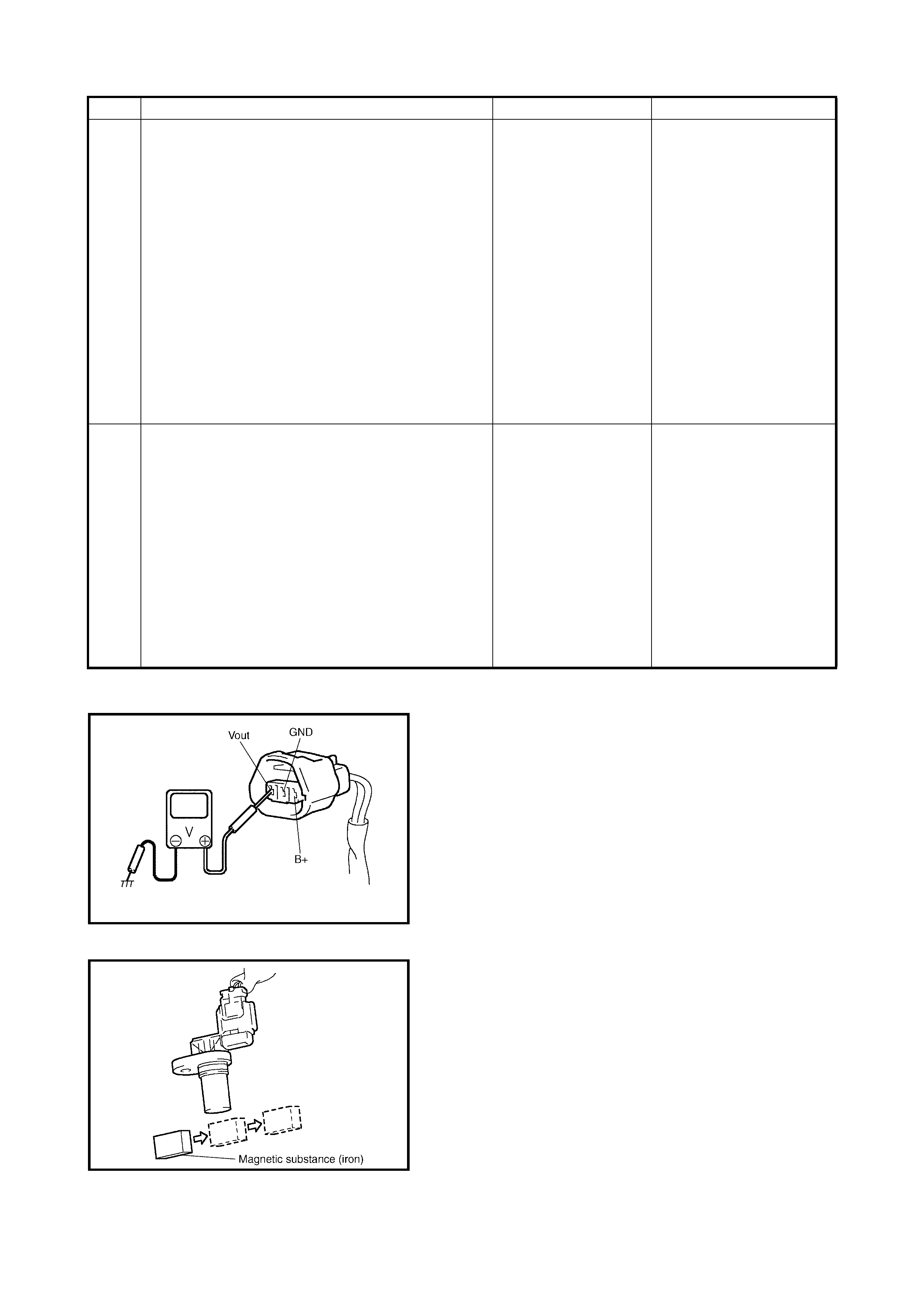
Fig. 1 for Step 3
Fig. 2 for Step 6
6 Check CMP Sensor for Operation.
1. Remove CMP sensor from sensor case.
2. Remove metal particles on end face of CMP
sensor, if any.
3. Connect each connector to ECM and CMP
sensor.
4. Turn ignition swi tc h ON.
5. Check for voltage at terminal C42-11 of
connector while connected to the ECM by
passing a magnetic substance (iron) while
keeping approximately 1 mm gap with
respect to end face of CMP sensor. See Fig.
2 and 3.
Does voltage vary from low (0 – 1 V) to high (4 – 5
V) or from high to low?
Go to Step 7. Replace CMP sensor.
7 Check Signal Rotor for the following.
See Fig. 4.
•Damage
• No foreign material attached
Is it in good condition?
Intermittent trouble or
faulty ECM.
Check for intermit-
tent, refer to
1.7 ELECTRICAL
CIRCUIT
INSPECTION
PROCEDURE -
INTERMITTENT
AND POOR
CONNECTIONin
Section 0A.
Clean rotor teeth or
replace CMP sensor.
Step Action Yes No
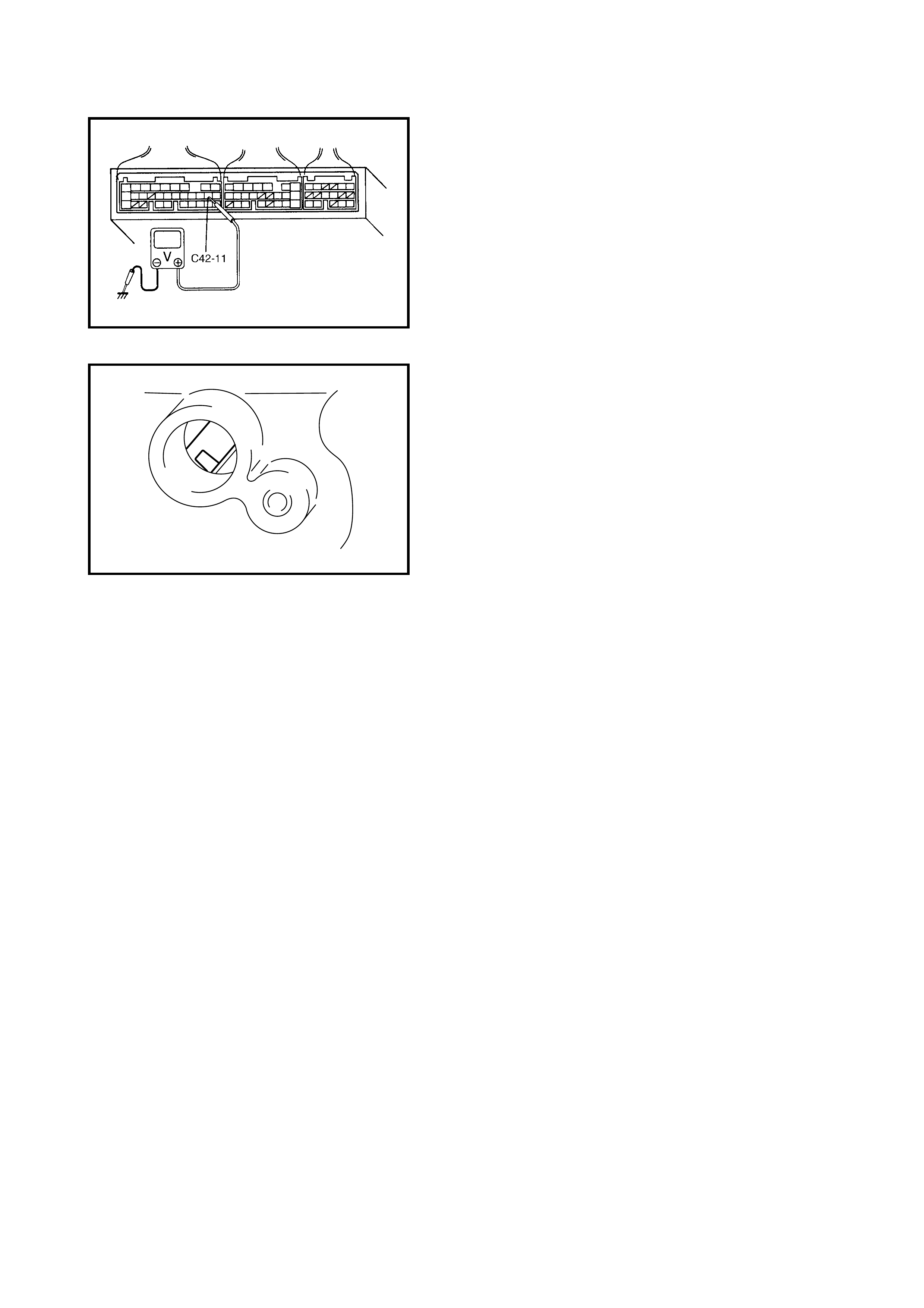
Fig. 3 for Step 6
Fig. 4 for Step 7
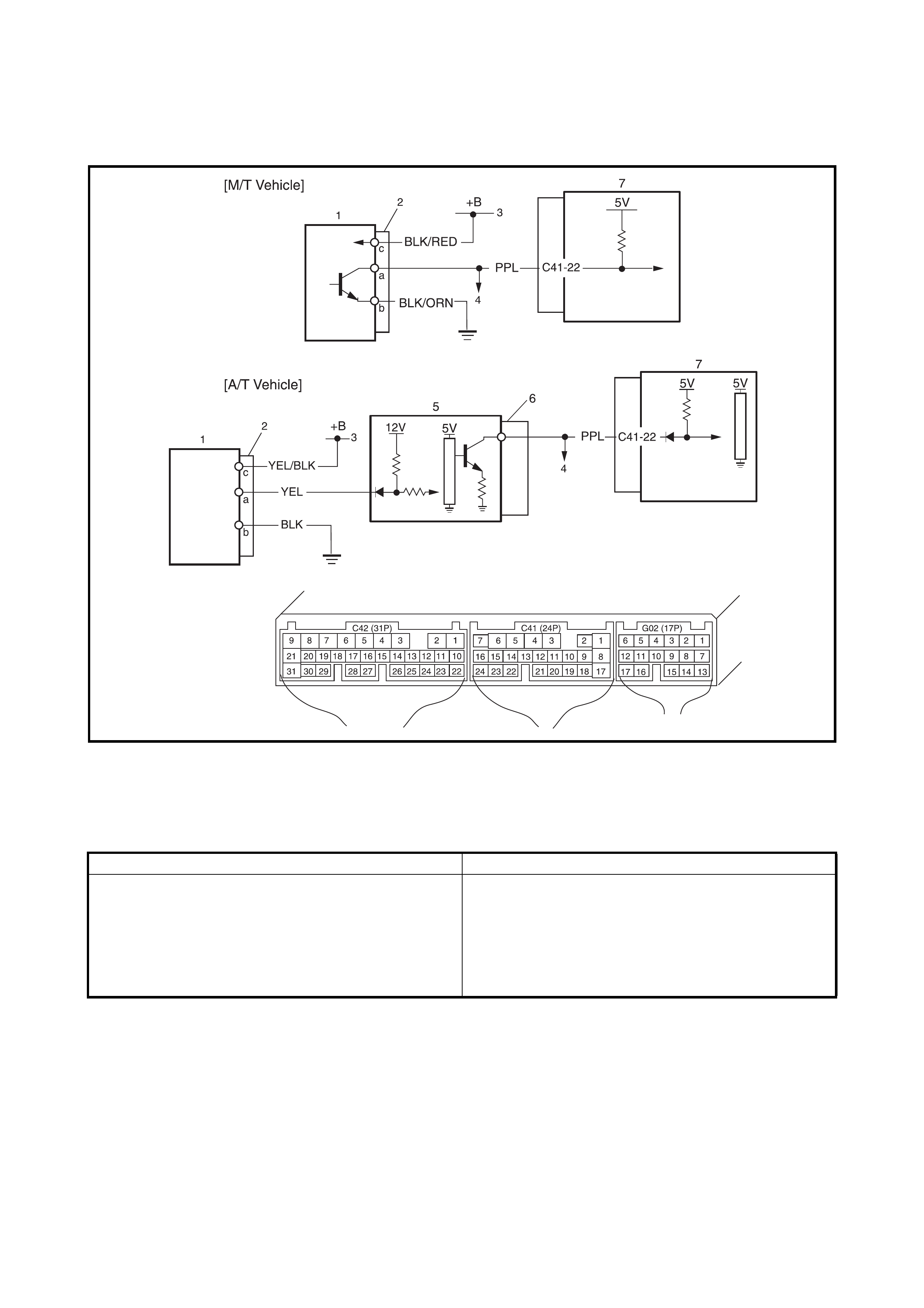
2.22 DTC P0500 (DTC NO.16) VE HICLE SPEED SENSOR (VSS) MALFUNCTION
WIRING DIAGRAM / CIRCUIT DESCRIPTION
Legend
DTC CONFIRMATION PRO CEDURE
WARNING:
• When performing a road test, select a place whe re there is no traffic or possibility of an accident.
Take care during testing.
• Road test should be carried out with 2 persons, a driver and a tester.
1. Clear DTC and warm up engine to normal operating temperature.
2. Increase vehicle speed to 80 km/h in 3rd gear or 2 range while observing vehicle speed displayed on
Tech 2.
3. Relea se ac celerato r ped al and w ith eng ine brake ap plied , keep vehic le coas ting ( fuel c ut con dition ) for 4
sec. or more.
4. Check DTC using diagnosis connector No. 1 or Tech 2.
1. VSS (vehicle speed sensor) 4. T o S peedometer , P/S control module 7. ECM
2. VSS connector 5. TCM
3. Power supply from ignition switch 6. TCM Connector
DTC DETECTING CONDITION POSSIBLE CAUSE
• No VSS signal input while vehicle running in D
range or during fuel cut at deceleration. • BLK/ORN circuit open
• PPL or BLK/RED circuit open or short
• VSS malfunction
• ECM malfunction
• Speedometer malfunction
• TCM Malfunction

INSPECTION
Step Action Yes No
1 Was ENGINE DIAG. FLOW TABLE performed? Go to Step 2. Go to 2.4 ENGINE DIAG.
FLOW TABLE.
2 Is vehicle equipped with A/T? Go to Step 9. Go to Step 3.
3 Does speedometer indicate vehicle speed? Go to Step 4. Go to Step 6.
4 Check Vehicle Speed Signal.
Is vehicle speed displayed on Tech 2 in step 2 and 3 of
DTC confirm at ion proce dure ?
Intermittent trouble or
faul ty ECM.
Check for intermittent,
refer to
1.7 ELECTRICAL
CIRCUIT INSPECTION
PROCEDURE -
INTERMITTENT AND
POOR CONNECTION
in Section 0A.
Go to Step 4.
5 Check VSS Signal Circuit.
1. Turn ignition switch to OFF position.
2. Disconnect combination meter connectors, refer
to Section 8.
3. Disconnect P/S control module connector.
4. Turn ignition switch to ON position, without
running engine.
5. Measure voltage from terminal a of VSS
connector to ground.
Is voltage within 4 – 5 V?
Faulty speedometer.
Faulty P/S control mod-
ule.
PPL wire open or short.
Poor connection of ECM
connector terminal.
If OK, substitute a known-
good ECM and rec hec k.
6 Check VSS Power Supply.
1. With ignition switch at O FF position, disconnect
VSS connector.
2. Turn ignition switch to ON position, without
running engine.
3. Measure voltage from terminal b to c of VSS
connector. See Fig. 1.
Is voltage within 10 – 14 V?
Go to Step 7. BLK/RED or BLK/ORN wire
open or short.
7 Check VSS Signal Circuit.
1. Measure voltage from terminal a of VSS
connector to ground.
Is voltage more than 4 V?
Go to Step 8. PPL wire open or short.
Poor connection of ECM
connector terminal.
If OK, substitute a known-
good ECM and rec hec k.
8 Check speedometer drive gear.
1. Remove VSS.
2. Visually inspect speedometer drive gear for
damage.
Was any damage found?
Faulty speedometer
drive gear. Poor connection of VSS
connector terminal.
If OK, substitute a known-
good VSS and recheck.
9 Does speedometer indicate vehicle speed? Go to Step 10. Go to Step 11.
10 Check VSS Signal circuit.
1. Turn ignition switch to OFF position.
2. Disconnect combination meter connectors, refer
to Section 8.
3. Disconnect P/S control module connector.
4. T urn ignition switch to ON pos ition without en gine
running.
5. Measure voltage from terminal PPL wire of TCM
connector to ground.
Is voltage within 4 – 5 V?
Intermittent trouble or
faul ty ECM.
Check for intermittent,
refer to
1.7 ELECTRICAL
CIRCUIT INSPECTION
PROCEDURE -
INTERMITTENT AND
POOR CONNECTION
in Section 0A.
PPL wire open.
Poor connection of ECM
connector terminal.
If OK, substitute a known
good ECM and rec hec k.
11 Check VSS Signal Circuit.
1. Turn ignition switch to OFF position.
2. Disconnect connector from TCM.
3. Turn ignition switch to ON position without
running engine.
4. Measure voltage from terminal PPL wire of TCM
connector to ground.
Is voltage more than 4 V?
Go to Step 12. Go to Step 14.
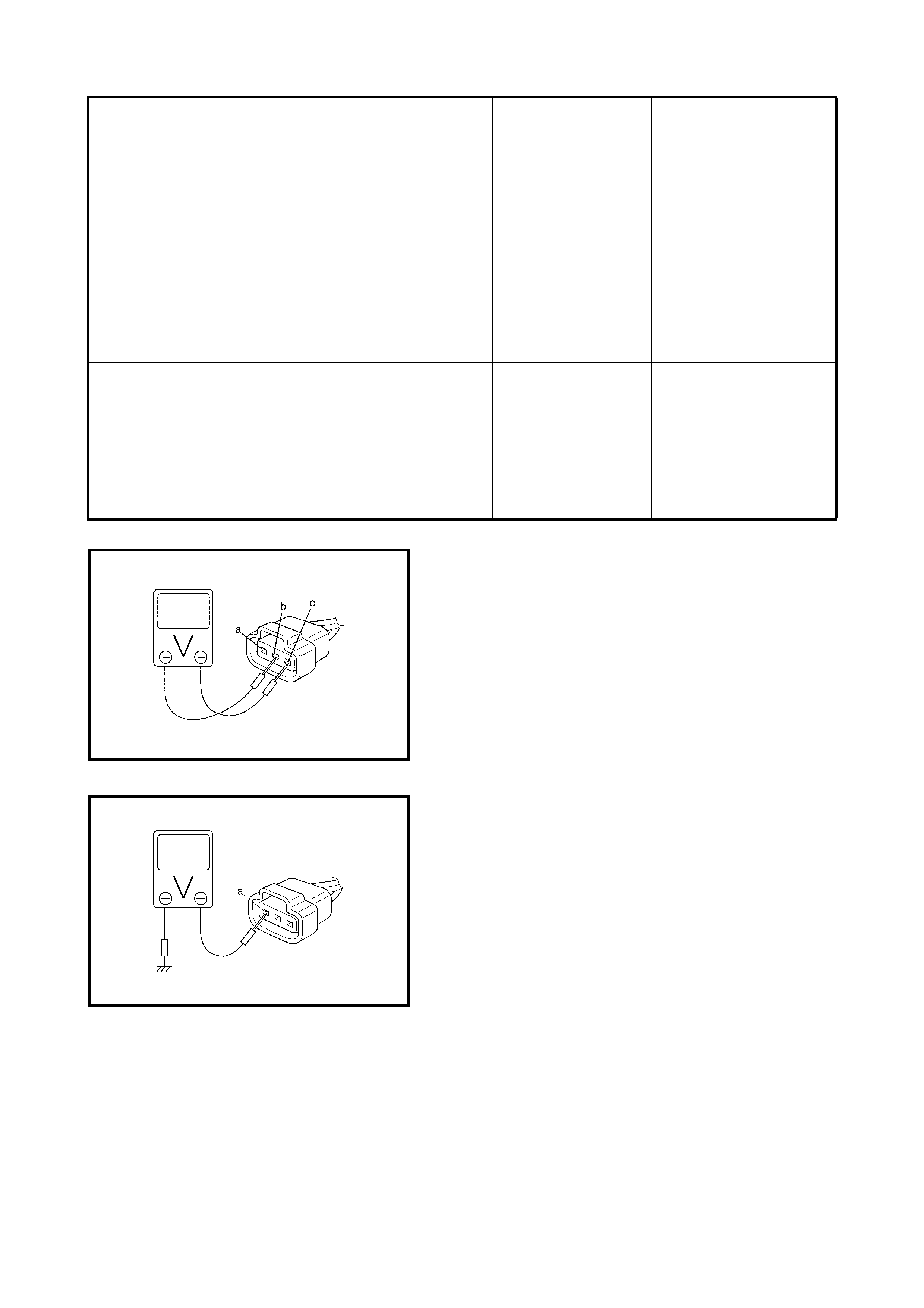
Fig. 1 for Step 5
Fig. 2 for Step 4 and Step 6
12 Check VSS circuit for short.
1. Turn ignition switch to OFF position.
2. Disconnect connector from ECM, combination
meter and P/S control module.
3. Turn ignition switch to ON position without
running engine.
4. Measure voltage from terminal PPL wire of TCM
connector to ground.
Is voltage within 0 V?
Go to Step 13. PPL wire short ed to power
supply.
13 Check VSS Circuit.
1. Check VSS circuit, refer to DTC P0720 OUTPUT
SPEED SENSOR (VSS) CIRCUIT
MALFUNCTION in Section 7B.
Is result satisfactory?
Go to Step 14. Repair or replace VSS cir-
cuit.
14 Check VSS circuit for short.
1. Turn ignition switch to OFF position.
2. Disconnect connector from combination meter
and P/S control module.
3. Turn ignition switch to ON position without
running engine.
4. Measure voltage from terminal G59-28 of TCM
connector to ground.
Is voltage within 4 – 5 V?
Faulty speedometer of
P/S control module. PPL wire op en or sho rted to
ground. Substitute a known
good ECM and rec hec k.
Step Action Yes No

2.23 DTC P1450 BAROMETRIC PRESS URE SENSOR LOW/HIGH INPUT
WIRING DIAGRAM / CIRCUIT DESCRIPTION
Barometric pressure sensor is installed in ECM.
DTC CONFIRMATION PRO CEDURE
1. Turn ignition switch OFF.
2. Clear DTC with ignition switch ON.
3. Turn ignition switch ON for 2 sec., crank engine for 2 sec. and run it at idle for 1 min.
4. Check DTC, refer 2.4 ENGINE DIAGNOSTIC FLOW TABLE.
INSPECTION
Substitute a known-good ECM and recheck.
DTC DETECTING CONDITION POSSIBLE CAUSE
Barometric pressure: Sensor voltage is 4.7 V or
higher, or 1.6 V or lower • ECM (barometric pressure sensor) malfunction
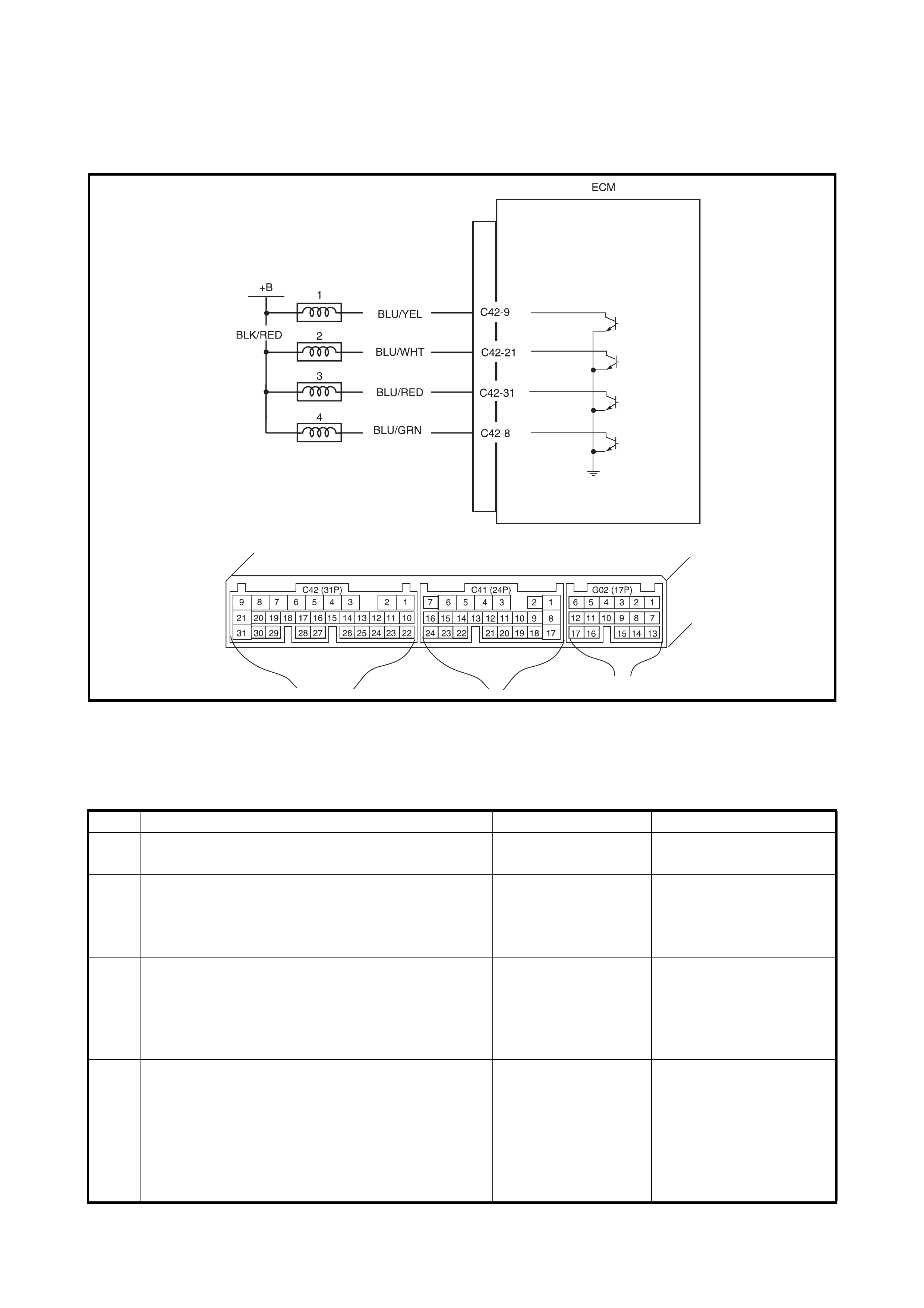
2.24 TABLE B-1 FUEL INJECTOR CIRCUIT CHECK
WIRING DIAGRAM
Legend
INSPECTION
1. No.1 injector 3. No.3 injector
2. No.2 injector 4. No.4 injector
Step Action Yes No
1 Was ENGINE DIAG. FLOW TABLE performed? Go to Step 2. 2.4 Go to ENGINE DIAG.
FLOW TABLE.
2 Check Injector for operating sound.
Using sound scope, check each injector for oper-
ating sound at engine cranking.
Do all 4 injectors make operating sound?
Fuel injector circuit is
in good condition. Go to Step 3.
3 Does none of 4 injectors make operating sound at
Step 2? Go to Step 4. Check connection and
wire harness of injector
not making operating
sound and injector itself,
refer to Section 6E1.
4 Check power circuit of injectors for open and
short.
Is it normal?
Check all 4 injectors
for resistance respec-
tively.
If resistance is OK,
substitute a known-
good ECM and
recheck.
Power circuit open or
short.
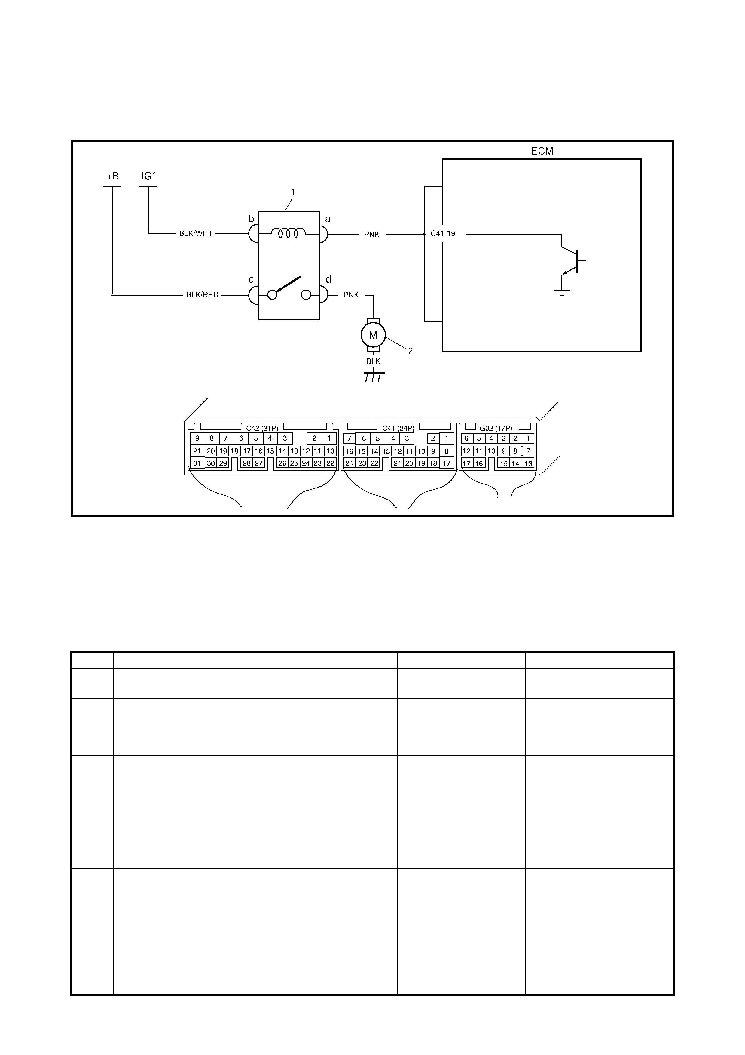
2.25 TABLE B-2 FUEL PUMP AND CIRCUIT CHECK
WIRING DIAGRAM
Legend
INSPECTION
CAUTION:
Check to make sure that connection is made between correct terminals. Wrong con-
nection can cause damage to ECM, wire harness, etc.
1. Fuel pump relay
2. Fuel pump
Step Action Yes No
1 Was ENGINE DIAG. FLOW TABLE performed? Go to Step 2. Go to 2.4 ENGINE DIAG.
FLOW TABLE.
2 Check Fuel Pump Control System for operation. See
Fig. 1.
Is fuel pump heard to operate for 2 sec. after ignition
switch ON?
Fuel pump circuit is in
good condition. Go to Step 3.
3 Check Fuel Pump for operation.
1. Remove fuel pump relay from relay box with
ignition sw i t ch OFF.
2. Check for proper connection to relay at each
terminal.
3. If OK, using se rvice wi re, connect te rminals c an d
d of relay connector. See Fig. 2.
Is fuel pump heard to operate at ignition switch ON?
Go to Step 4. PNK, BLK or BLK/RED cir-
cuit open or fuel pump mal-
function.
4 Check Fuel Pump Relay for operation.
1. Check resistance between each two terminals of
fuel pump relay. See Fig.3.
Between terminals c and d: Infinity
Between terminals a and b: 56 – 146 Ω
2. Che c k that there is continu ity between terminal s c
and d wh en battery is connec ted to term inals a and
b. See Fig. 3.
Is fuel pump relay in good condition?
PNK circuit open or
poor C 41-19 connec-
tion.
If wire and connection
are
OK, substitute a known-
good ECM and recheck.
Replac e fuel pump
relay.
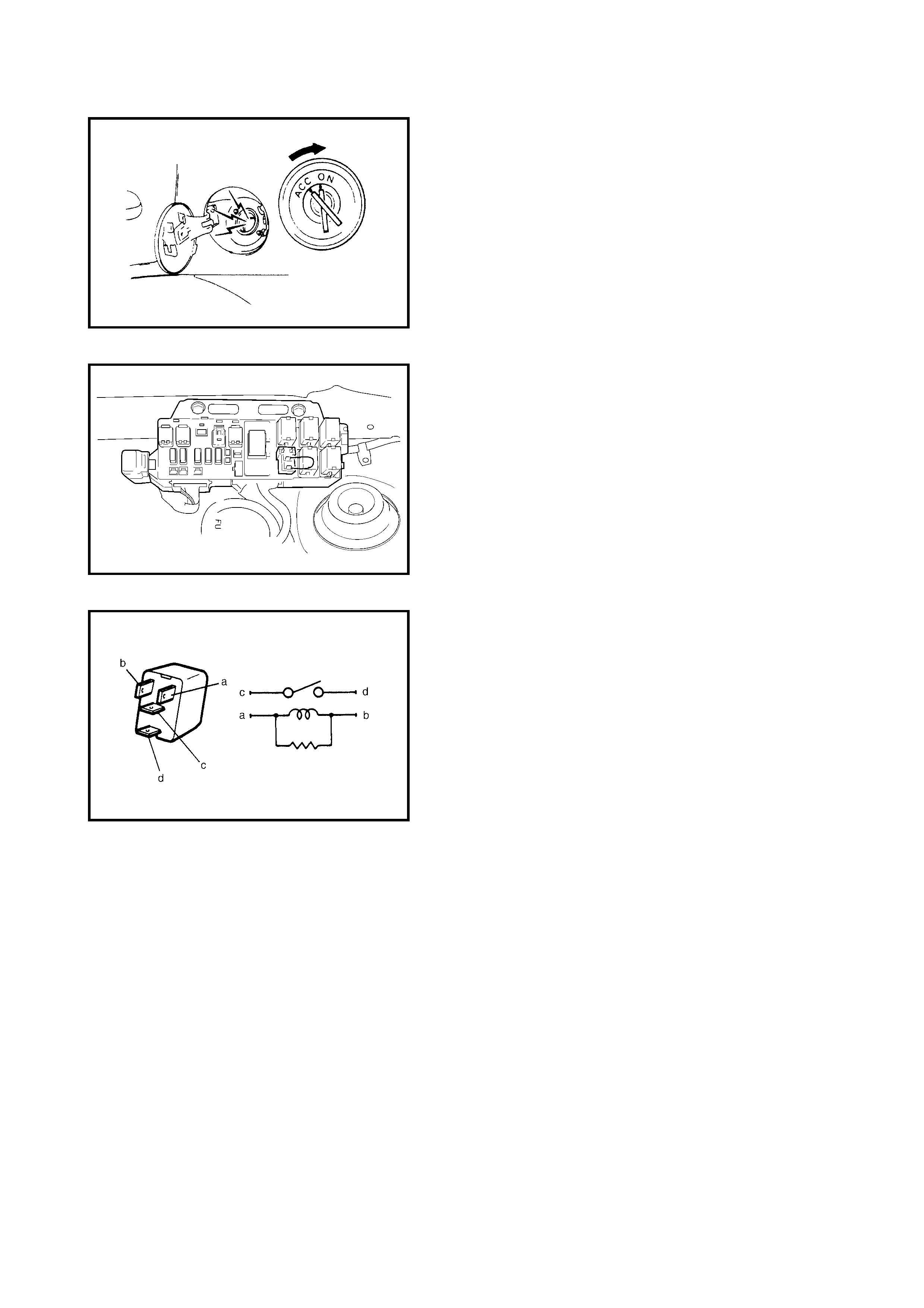
Fig. 1 for Step 2
Fig. 2 for Step 3
Fig. 3 for Step 4
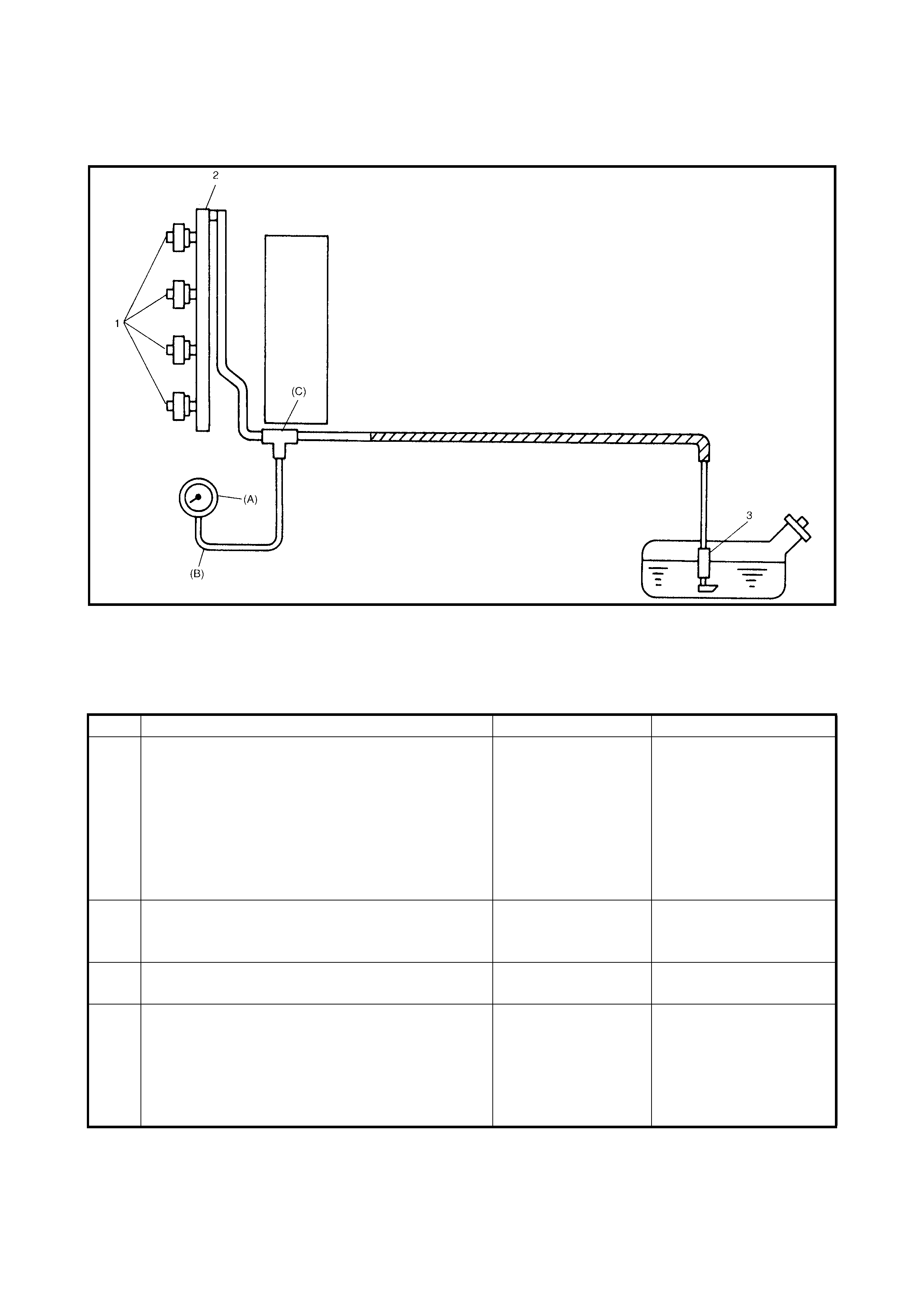
2.26 TABLE B-3 FUEL PRESSURE CHECK
WIRING DIAGRAM
Legend
INSPECTION
1. In jec to r 3. F u el pum p (B): Hose
2. Delivery pipe (A): Fuel pressure gauge (C): Attachment
Step Action Yes No
1 Check Fuel Pressure, refer to Section 6E1 for
details.
1. Release fuel pressure from fuel feed line.
2. Install fuel pressure gauge.
3. Check fuel pressure by repeating ignition
switch ON and OFF. See Fig. 1.
Is fuel pressure then 270 – 310 kPa (38.4 – 44.0
psi)?
Go to Step 2. Go to Step 4.
2 Is 250 kPa (35.6 psi) or higher fuel pressure
retained for 1 minute after fuel pump is stopped at
Step 1?
Normal fuel pressure. Go to Step 3.
3 Is there fuel leakage from fuel feed line hose, pipe
or joint? Rectify fuel leakage. Faulty fuel pressure regu-
lator.
4 Was fuel pressure higher than spec. in Step 1? Faulty fuel pressure
regulator. Clogged fuel filter,
Restricted fuel feed hose
or pipe, Faulty fuel pump
or Fuel leakage from
hose conne cti on in fuel
tank.
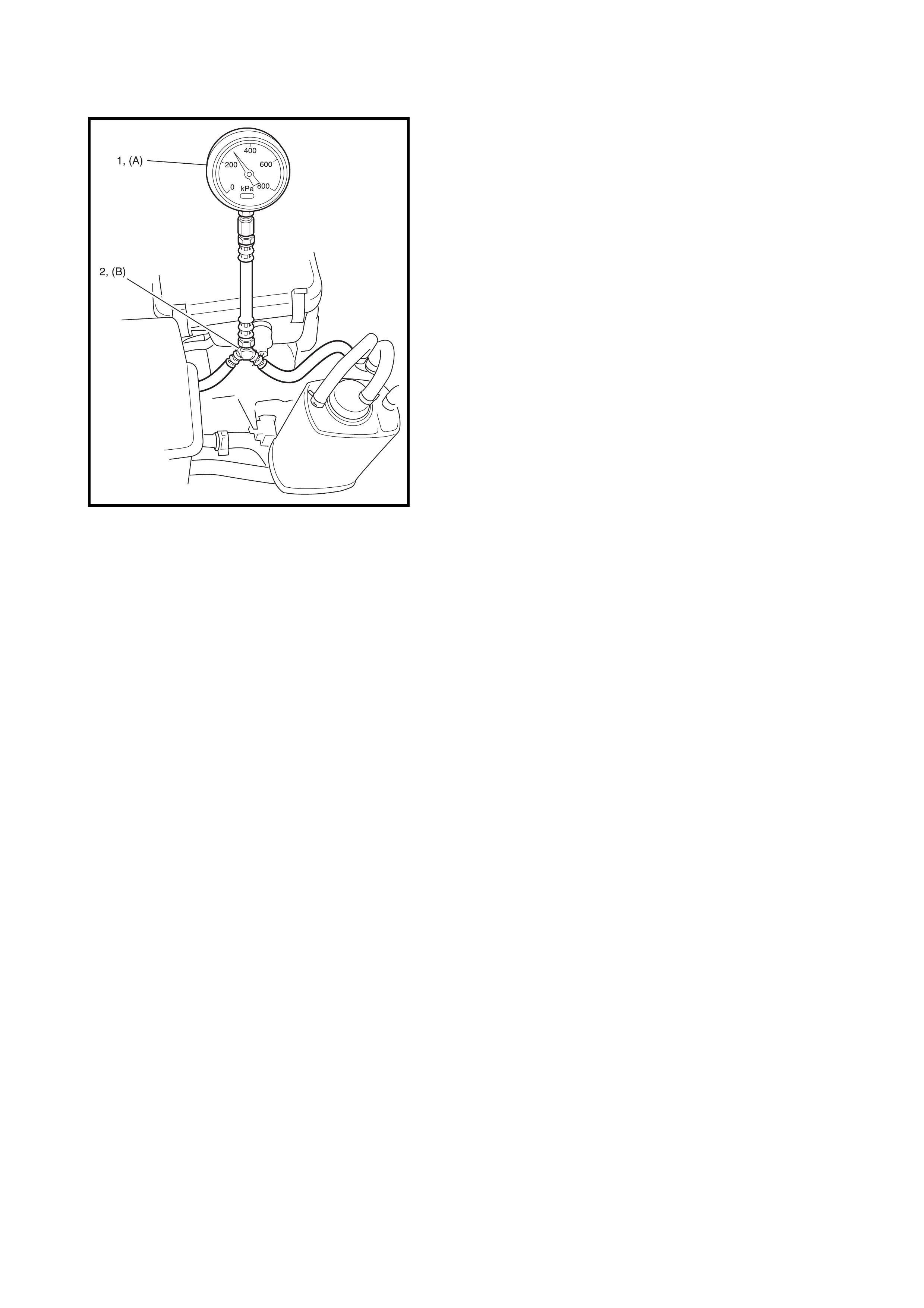
Fig. 1 for Step 1 Legend
1. Fuel pressure gauge
2. 3 way joint
(A): Special tool SD28018 or AU338
(B): Special tool SD28057
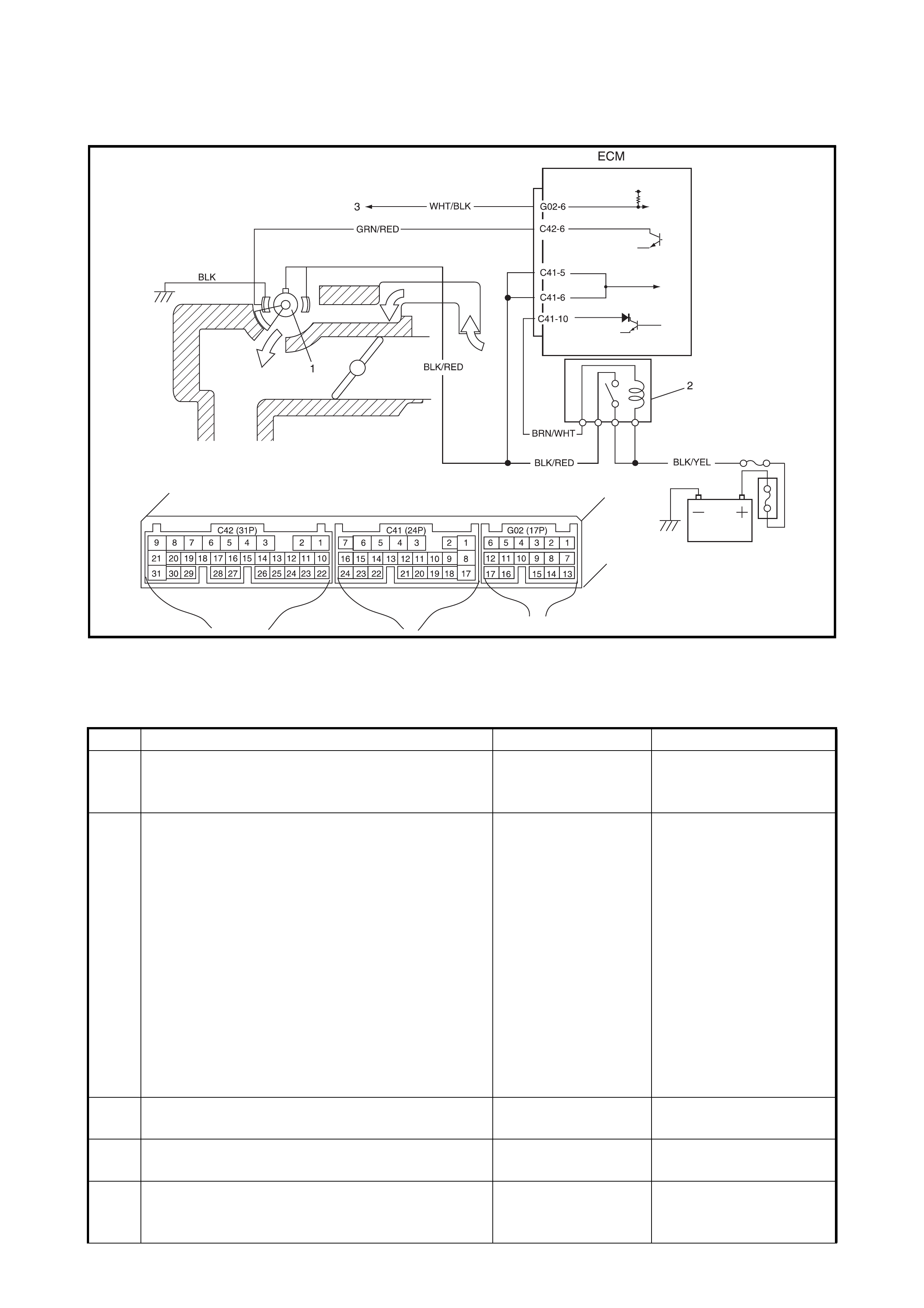
2.27 TABLE B-4 IDLE AIR CONTROL SYSTEM CHECK
Legend
INSPECTION
1. IAC valve 2. Main relay 3. To TCM
Step Action Yes No
1 Check engine idle speed and IAC duty, refer to 2.
ON-VEHICLE SERVICE in Section 6E1.
Is idle speed within specification?
Go to Step 2. Go to Step 4.
2 Is IAC duty within specification in Step 1? Go to Step 3. Check for following:
• Vacuum leak.
• EVAP canister purge
control system.
• Clog of IAC air pas-
sage.
• Accessory engine
load, refer
2.29 TABLE B-6
ELECTRIC LOAD
SIGNAL CHECK.
• Closed throttle posi-
tion (TP sensor)
• Stuck PCV valve.
3 Is engine idle speed kept specified even with
headlights ON? System is in good
condition. Go to Step 7.
4 Was idle speed higher than specification in Step
1? Go to Step 5. Go to Step 6.
5 Check A/C (input) signal circuit, refer to Step 1 of
2.28 TABLE B-5 A/C SIGNAL CIRCUIT CHECK.
Is it in good condition?
Go to Step 7. Repair or replace A/C
signal circuit or A/C sys-
tem.
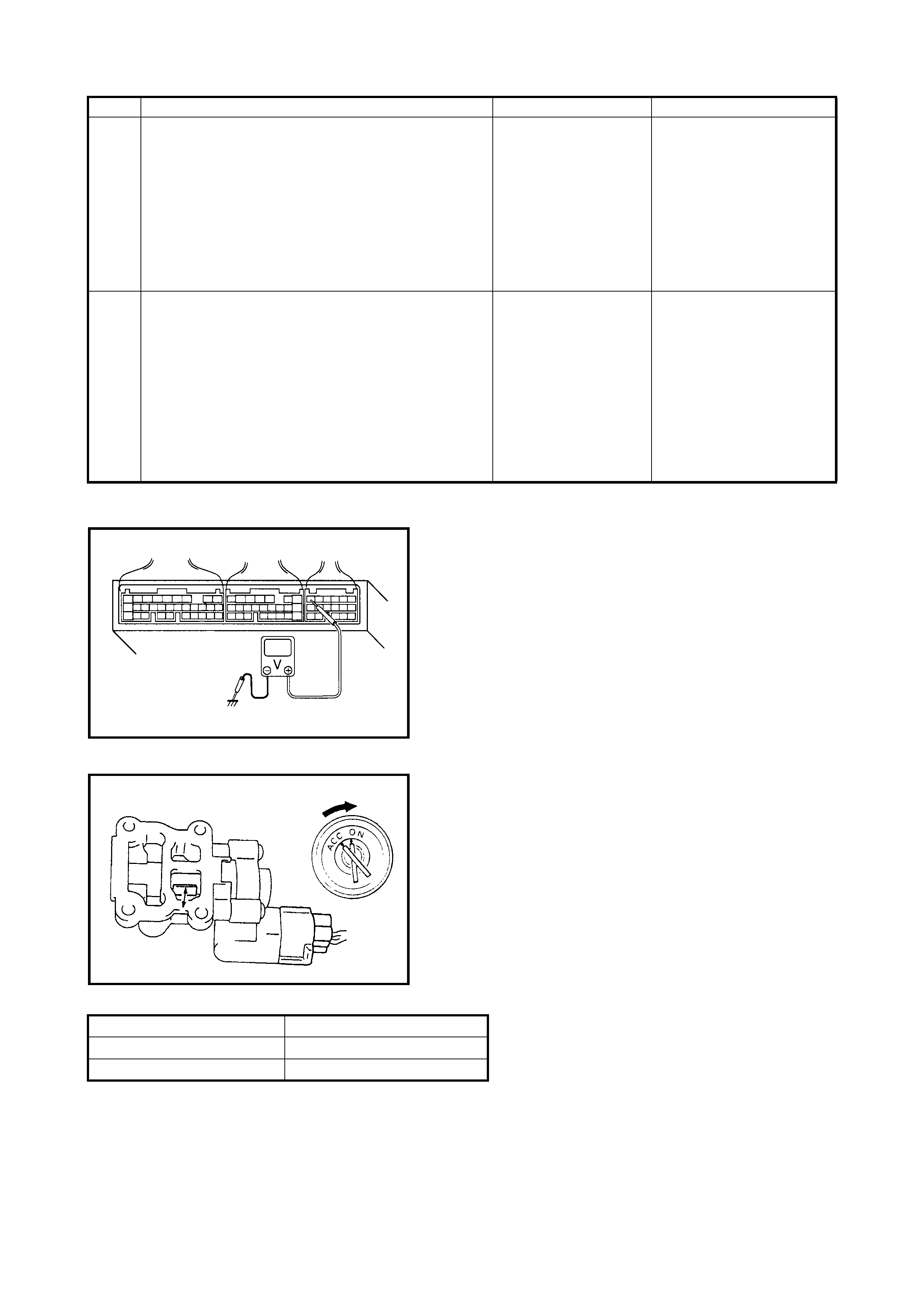
Fig. 1 for Step 6
Fig. 2 for Step 7
Table 1 for Step 6
7 Check Idle Air Control System.
1. Remove IAC valve from thro ttl e bod y, refer to 2.1
AIR INTAKE SYSTEM - IAC VALVE, REMOVAL
in Section 6E1.
2. Check IAC valve for operation, refer to 2.1 AIR
INTAKE SYSTEM - IAC VALVE, INSPECTION in
Section 6E1. See Fig.2.
Is check result satisfactory?
Intermittent trouble or
faul ty ECM.
Check for intermittent,
refer to
1.7 ELECTRICAL
CIRCUIT INSPECTION
PROCEDURE -
INTERMITTENT AND
POOR CONNECTION
in Section 0A.
Go to Step 8.
8 Check Wire Harness for Open or Short.
1. Turn igni tion swi tch O FF.
2. Disconnect IAC valve connector.
3. Check fo r proper conne cti on to I A C v al ve a t each
terminal.
4. If OK, disconnect ECM connector.
5. Check for proper connection to ECM at C42-6
terminal.
6. If OK, check BLK/RED, GRN/RED and BLK
circuit for open or short.
Are t hey in good condition?
Replace IAC valve and
recheck. Repair or replace.
Step Action Yes No
Selector lever position Voltage at C41-14
P and N range 10 – 14 V
R, D, 2 and L range 0 – 1 V
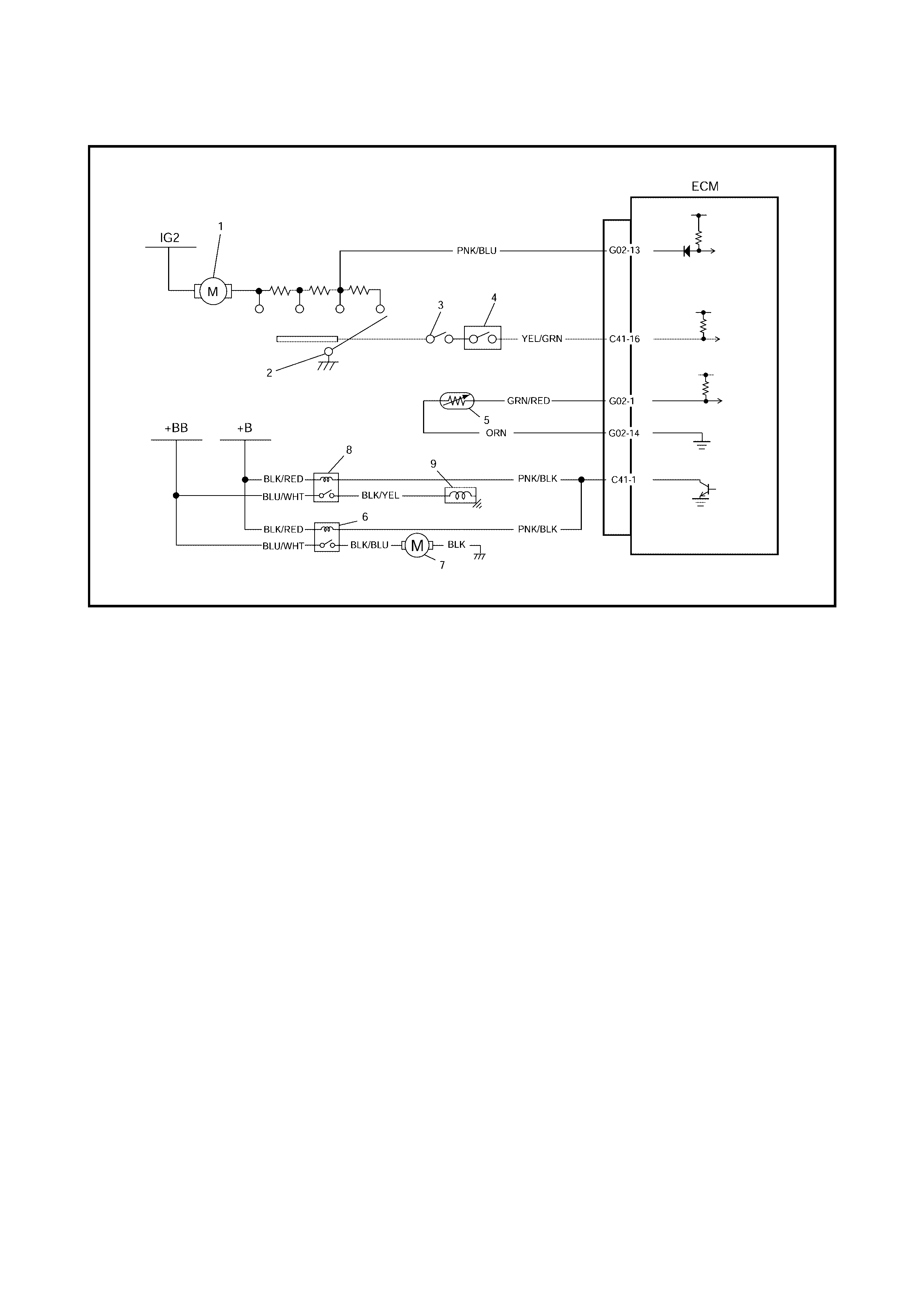
2.28 TABLE B-5 A/C SIGNAL CIRCUITS CHECK (VEHICLE WITH A/C)
Legend
1. Blower fan motor 4. A/C pressure switch 7. A/C condenser fan motor
2. Blower fan switch 5. A/C evaporator outlet air temp. sensor 8. A/C compressor relay
3. A/C switch 6. A/C condenser fan relay 9. A/C compressor
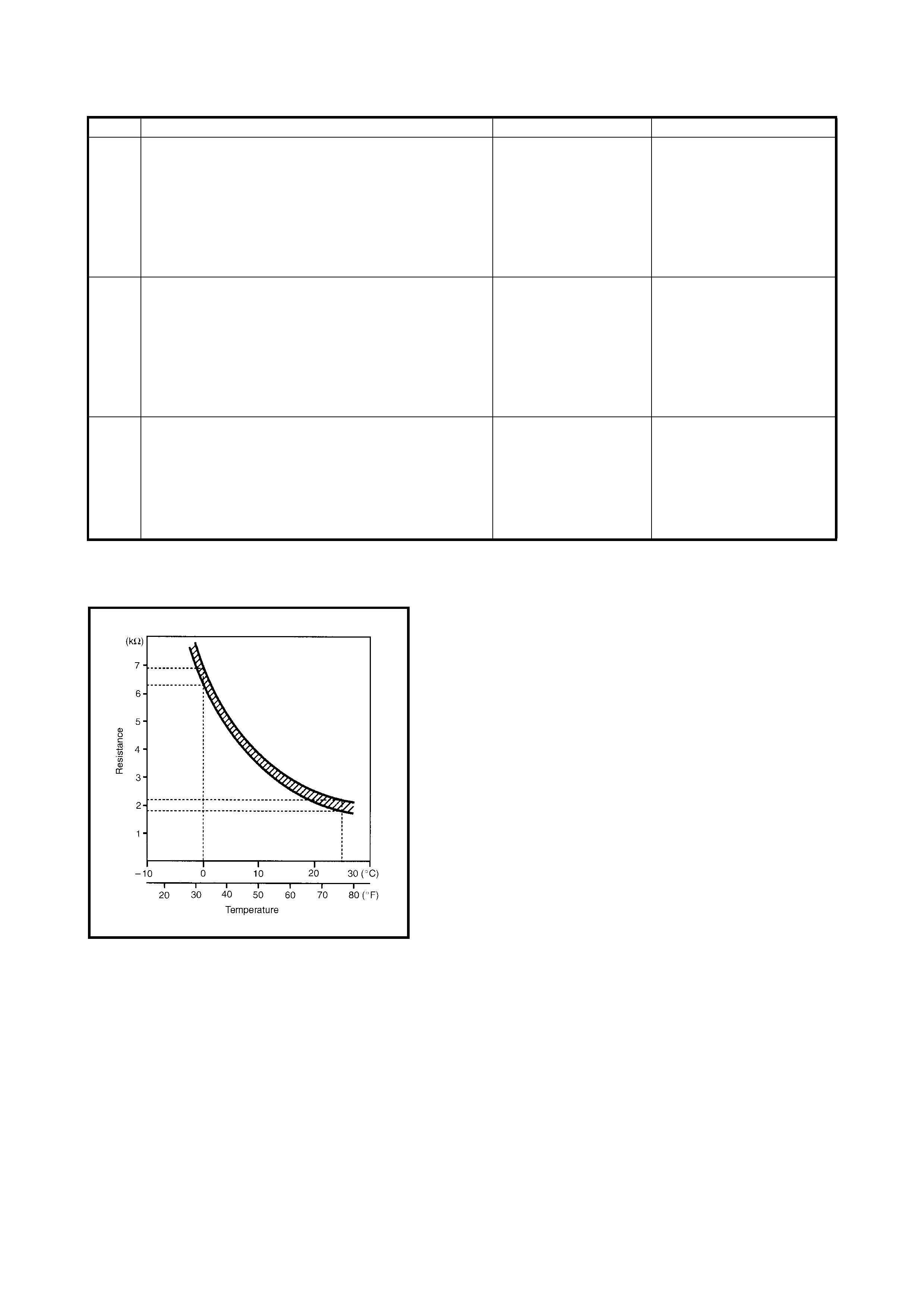
INSPECTION
NOTE:
When A/C evaporator th ermist or temp . is below 2.5°C, A/C remai ns OFF ( C41-1 terminal volt age
become 10 – 14 V). This condition is not abnormal.
Fig. 1 for Step 1
Step Action Yes No
1 Check Evaporator Temp. Sensor Resistance.
1. Disconnect ECM connectors with ignition switch
at OFF position.
2. Check resistance between G02-14 terminal and
G02-10 terminal. See Fig. 1.
Is it within specification?
At 0°C 6.3 – 6.9 kΩ
At 25°C 1.8 – 2.2 kΩ
Go to Step 2. Faulty A/C evaporator temp.
sensor or its circuit.
2 Check A/C Switch Signal.
1. Check voltage at C41-16 terminal under each
con dition given bel ow.
Ignition switch ON A/C switch OFF: 10 – 14V
Ignition switch ON A/C switch ON: 0 – 1V
Is check result satisfactory?
Go to Step 3. YEL/GRN wire open or
short.
Poor C41-16 terminal con-
nection.
If wire and connection are
OK, substitute a known-
good ECM and rec hec k.
Go to Step 3.
3 1. Check voltage at C41-1 terminal under each
con dition given bel ow.
While engine running, A/C switch OFF: 10 – 14V
While engine running, A/C switch ON: 0V
Is check result satisfactory?
A/C control system cir-
cuit s are in good cond i-
tion.
PNK/BLK wire open or
short.
Poor C41- 1 ter minal con-
nection.
If wire and connection are
OK, substitute a known-
good ECM and rec hec k.
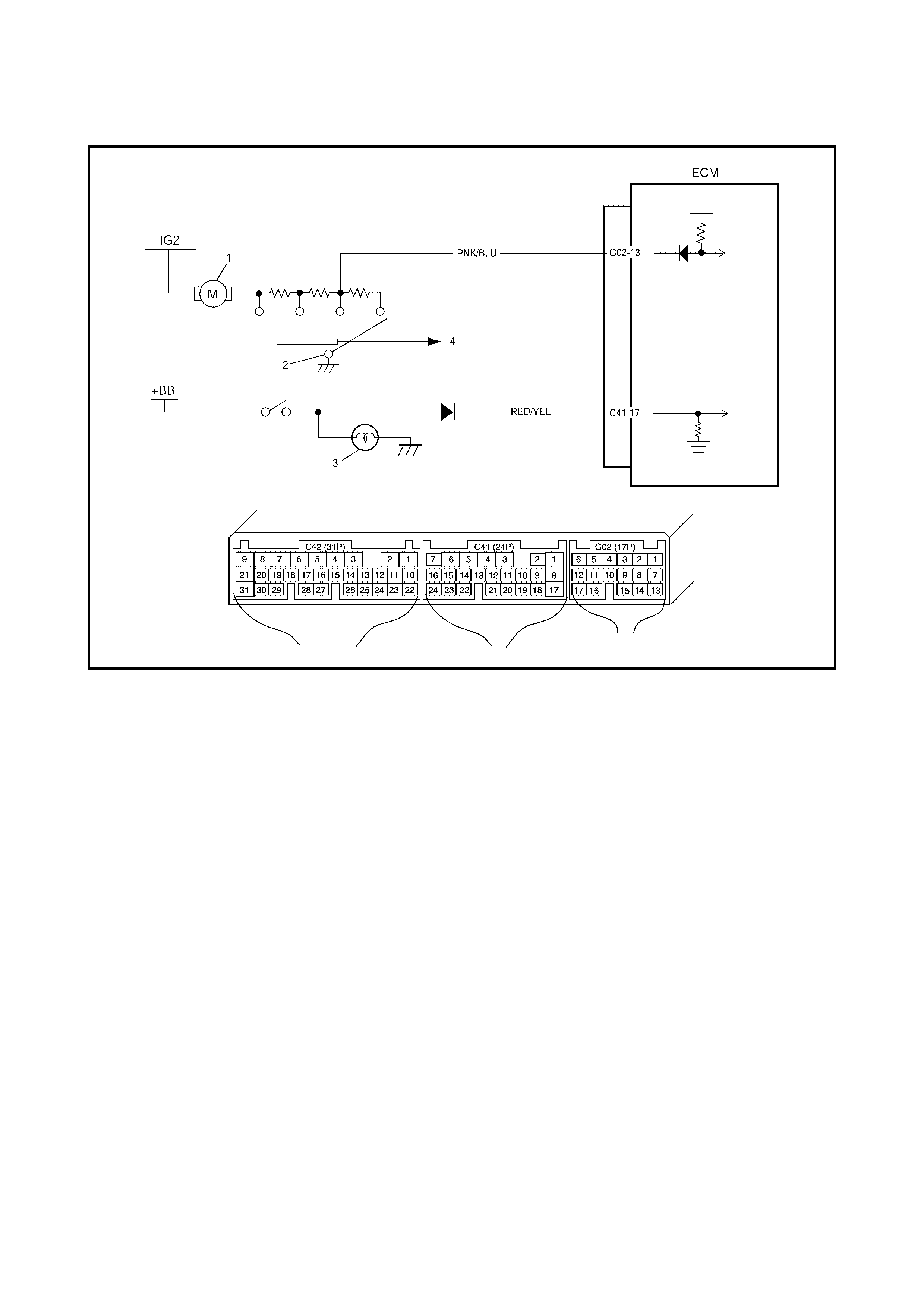
2.29 TABLE B-6 ELECTRIC LOAD SIGNAL CIRCUIT CHECK
Legend
1. Blower fan motor 3. Position lamp
2. Blower fan switch 4. To A/C switch
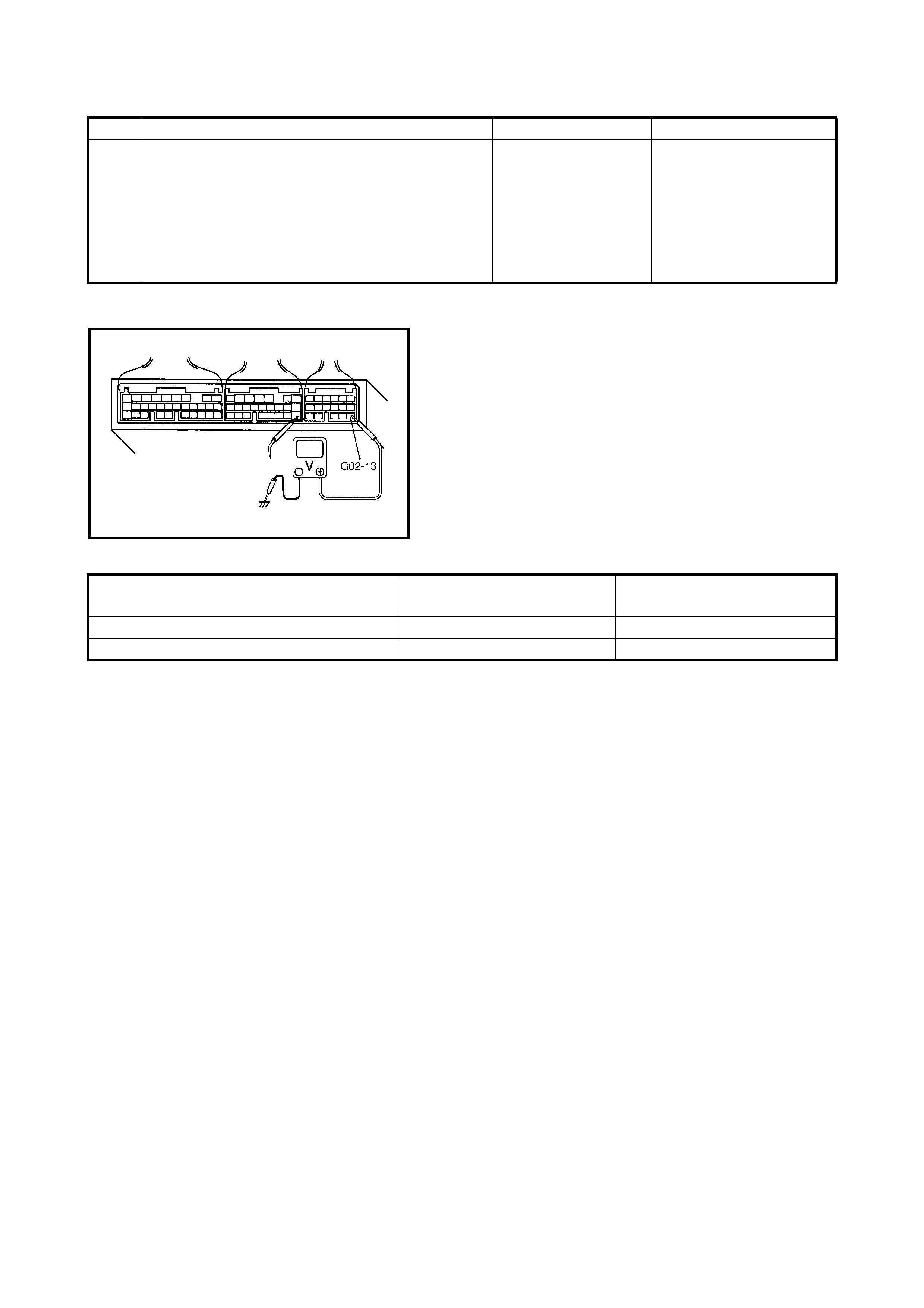
INSPECTION
Fig. 1 for Step 1
Table 1 for Step 1
Step Action Yes No
1 Check Electric Load Signal Circuit.
1. Turn ignition swi tc h ON.
2. Check voltage at terminals C41-17 and G02-
13 of ECM connector while connected,
under each condition. See Fig. 1 and Table
1.
Is each voltage as specified?
Electric load signal
circuit is in good con-
dition.
RED/YEL and/ or PNK/
BLU circuit open or short,
electric load diodes mal-
function or each electric
load circ ui t malfu nc tio n.
Ignition switch ON,
Small light and heater blower fan turned: VOLTAGE AT
C41-17 VOLTAGE AT
G02-13
OFF: 0V 10 – 14V
ON: 10 – 14V 0V

2.30 TABLE B-7 RADIATOR FAN CONTROL SYSTEM CHECK
Legend
INSPECTION
1. Radiator fan relay No.1 3. Radiator fan relay No.3
2. Radiator fan relay No.2 4. Radiator fan
Step Action Yes No
1 Check Fan Control System.
1. Connect Tech 2 to DLC with ignition swit ch OF F.
2. S t art engine an d select DAT A LIST mode on Tech
2.
3. Warm up engine until coolant temp. is 97.5°C or
higher and A/C switch turn OFF. (If engine
coolant te mp. do es not rise , check en gine cool ing
system or ECT sensor.) See Fig. 1.
Is radiator cooling fan started when engine coolant
temp. reaches above temp.?
Radia tor co oling fan
contr ol system i s in
good condition.
Go to Step 2.
2 Check Radiator Fan Relay and its Circuit.
1. Turn igni tion swi tch O N.
2. Check voltage at terminal C41-18 of ECM
connector while connected when engine coolant
temp. is lower than 97.5°C and A/C switch turns
off: 10 – 14 V.
Is check result satisfactory?
Check for intermittent,
refer to
1.7 ELECTRICAL
CIRCIT INSPECTION
PROCEDURE -
INTERMITTENT AND
POOR CONNECTION
in Section 0A. If wire
and c o nnection OK,
substitute a known
good ECM and recheck.
Go to Step 3.
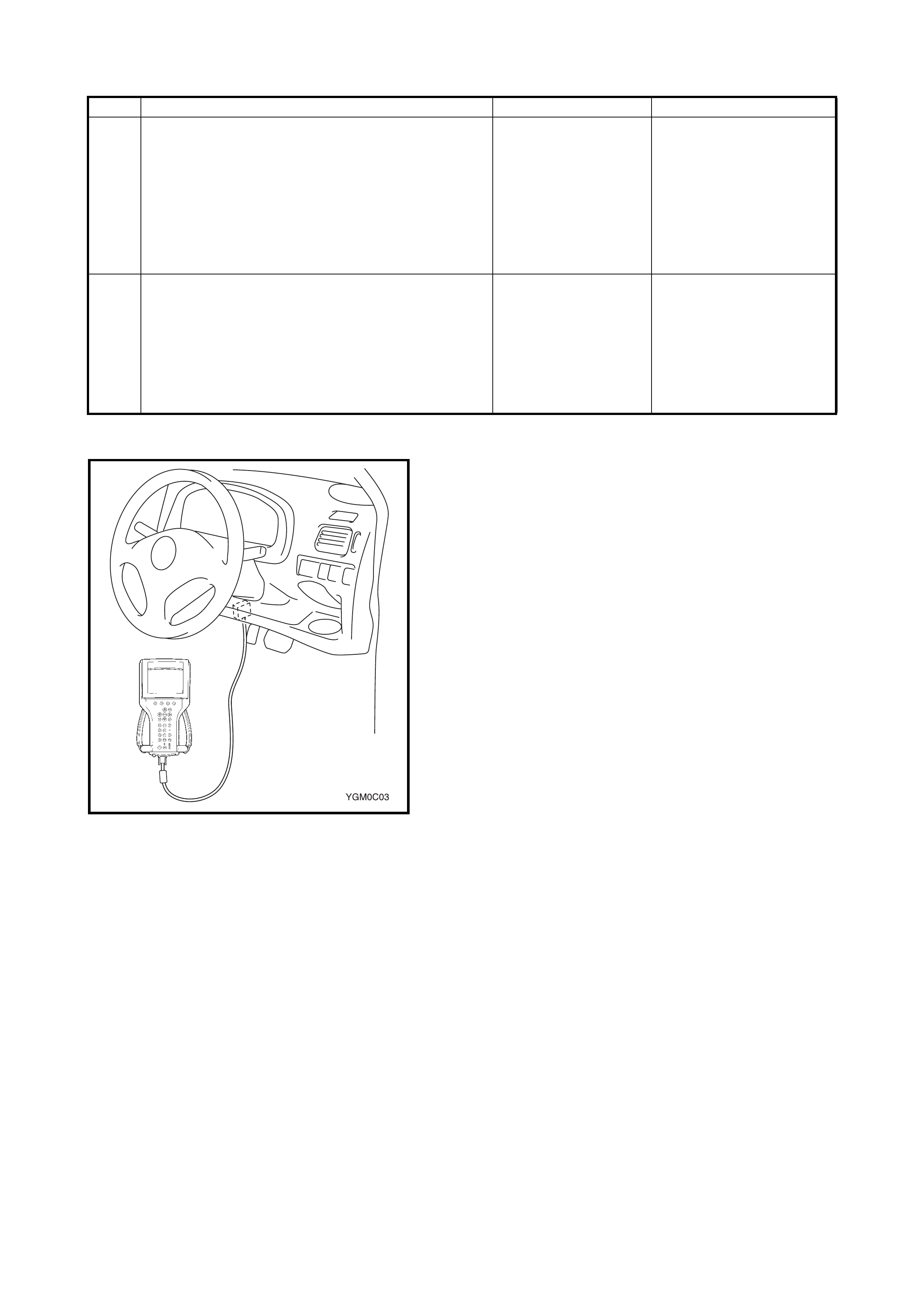
Fig. 1 for Step 1
3 Check Radiator Fan Relays.
1. Turn ignition switch OFF and remove radiator
cooling fan relays. (No.1 – No.3)
2. Check for proper connection to relay at terminals
c an d d.
3. If OK, check that there is continuity between c
and d when battery is connected to terminals a
and b. See Fig. 2.
Is check result satisfactory?
Go to Step 4. Re place radiator fa n
relay(s).
4 Check Radiator Fan.
1. Turn igni tion swi tch O FF.
2. Disconnect cooling fan motor connector.
3. Check for proper connection to motor at BLU/
RED and BLK terminals.
4. If OK, connect battery to motor and check for
operation. See Fig. 3.
Is it in good condition?
BLU/WHT, BLU/RED or
BLK circuit open. Replace radiator fan motor.
Step Action Yes No
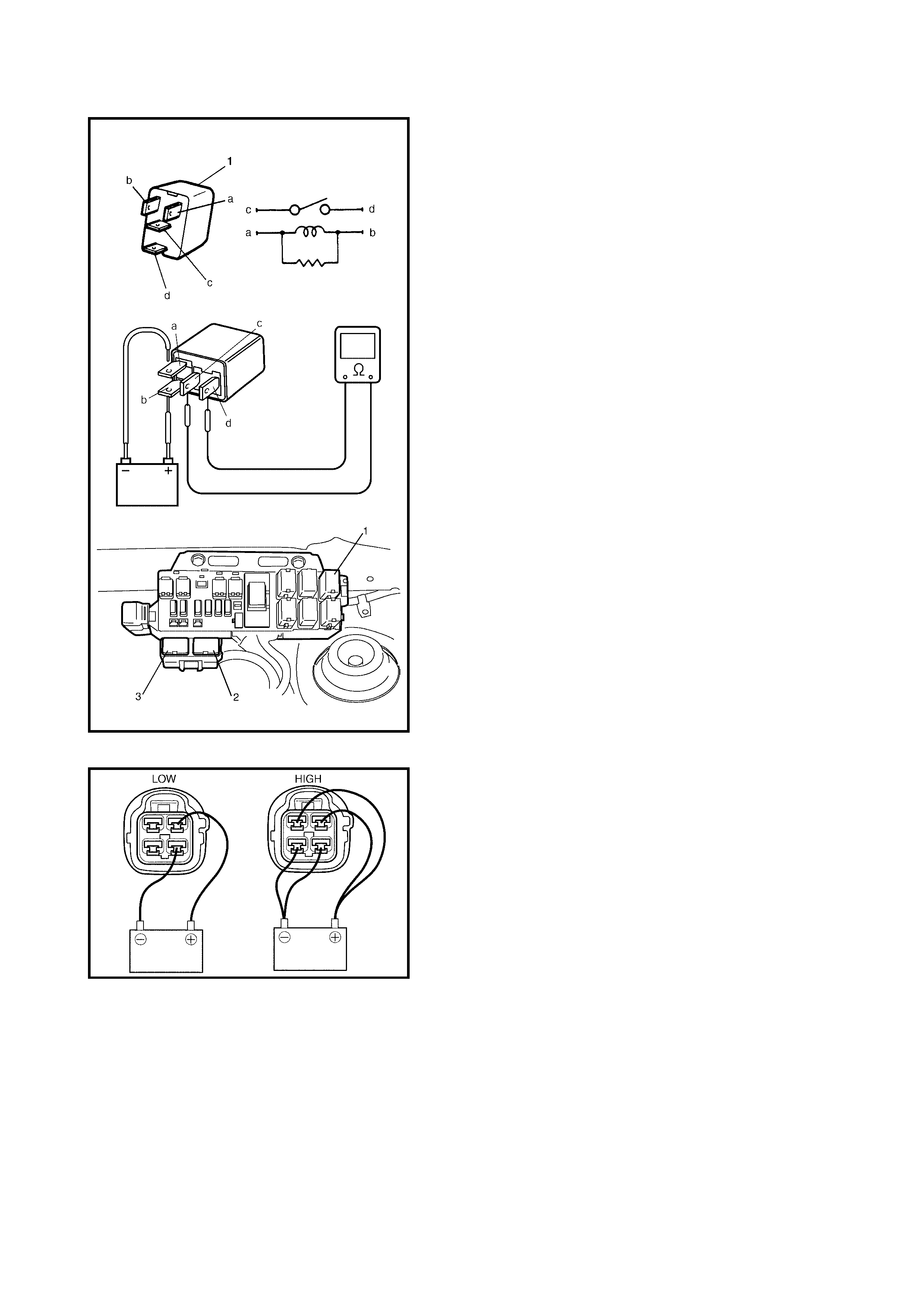
Fig. 2 for Step 3 Legend
Fig. 3 for Step 4
1. Radiator fan No.1
2. Radiator fan No.2
3. Radiator fan No.3
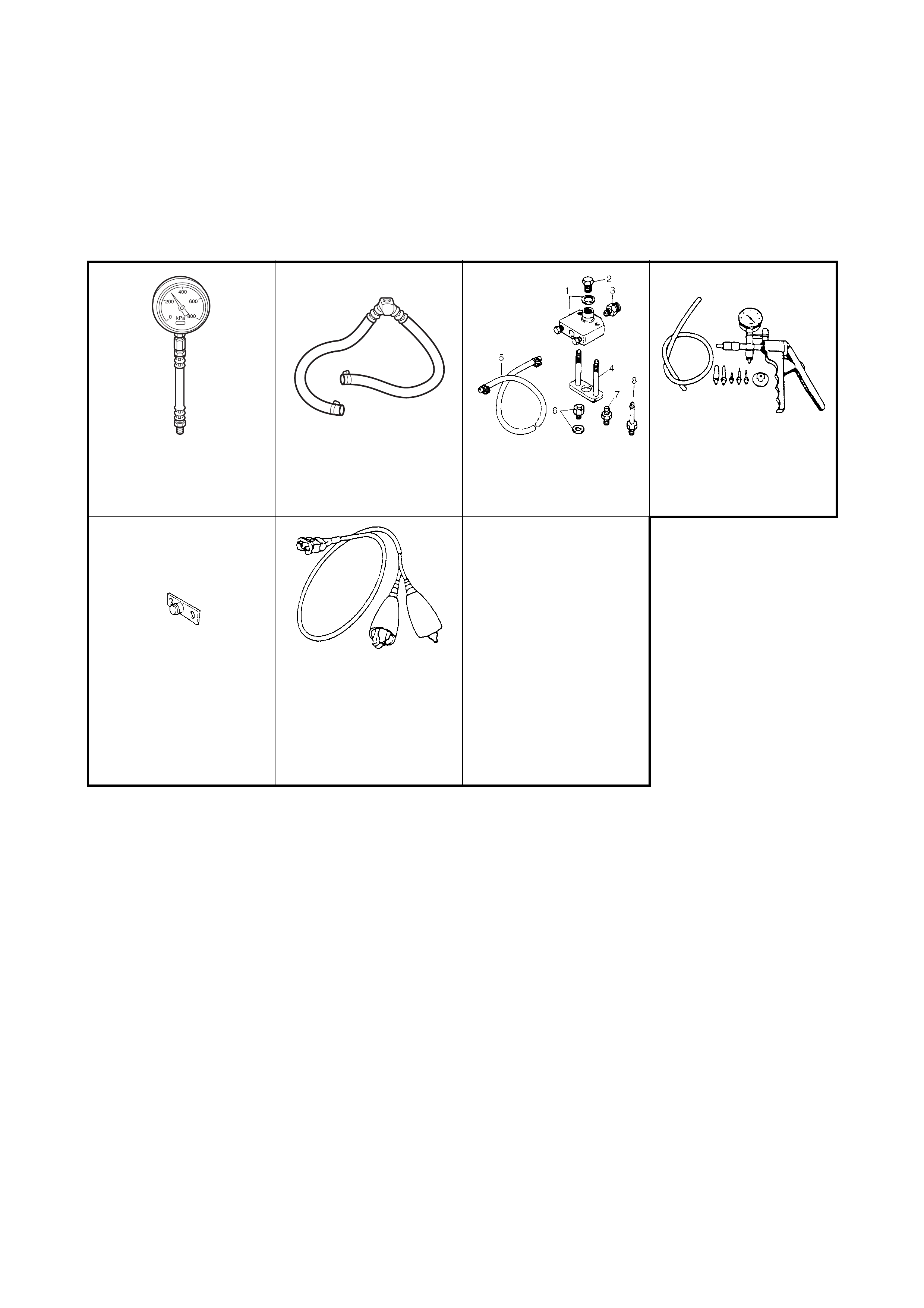
3. SPECIAL TO OLS
NOTE: Refer to Section 0A GENERAL INFORMATION – 7. CONSOLIDATED TOOLS for a detailed list of
special tools and the local equivalent if one is available.
NOTE
A:
This kit includes the following items:
1. Tool body & washer,
2. Body plug,
3. Body attachment,
4. Holder,
5. Return hose & clamp,
6. Body attachment-2 & washer,
7. Hose attachment- 1,
8. Hose attachment- 2.
SD28018 or AU338 SD28057 09912-5 842 1 09917-47010
Pressure gauge Fuel pressure gauge
hose Checking tool set
(See NOTE A.) Vacuum pump gauge
09912-57610 09930-88530
Checking tool plate Injector test lead Tech 2 kit
(see Note B)
NOTE B:
This kit includes the following items:
1. Tech 2,
2. PCMCIA card,
3. DLC cable,
4. SAE 16 / 19 adapter,
5. Cigarette cable,
6. DLC loopback adapter,
7. Battery power cable,
8. RS232 adapter,
9. RS232 loopback connector,
10. Storage case,
11. Power su ppl y.7 .