
SECTION 6B - ENGINE COOLING
1. GENERAL DESCRIPTION
1.1 COOLING SYSTEM CIRCULATION
1.2 COOLANT
Coolant Proportioning Table
Coolant Capacity
2. DIAGNOSIS
2.1 DIAGNOSIS TABLE
2.2 SYSTEM CIRCUIT
2.3 SYSTEM CIRCUIT INSPECTION
3. MAINTENANCE
3.1 COOLANT LEVEL CHECK
3.2 ENGINE COOLING SYSTEM
INSPECTION AND SERVICE
3.3 COOLING SYSTEM FLUSH AND REFILL
3.4 WATER PUMP / GENERATOR DRIVE
BELT TENSION INSPECTION
AND ADJUSTMENT
4. ON-VEHICLE SERVICE
4.1 SYSTEM COMPONENTS
4.2 COOLING SYSTEM DRAINING
4.3 COOLING SYSTEM REFILL
4.4 COOLING WATER PIPES OR HOSES
Removal
Installation
4.5 THERMOSTAT
Removal
Inspection
Installation
4.6 RADIATOR
Removal
Inspection
Cleaning
Installation
4.7 RADIATOR COOLING FAN
Inspection
Removal / Installation
4.8 RADIATOR COOLING FAN RELAY
Inspection
4.9 WATER PUMP / GENERATOR DRIVE
BELT
Removal
Installation
Water Pump Belt Tension Inspection
and Adjustment
4.10 WATER PUMP
Removal
Inspection
Installation
4.11 ECT SENSOR
5. REQUIRED SERVICE MATERIAL
1. GENERAL DESCRIPTION
The co oling syst em consists of the ra diator cap, radi ator, coolant reserv oir tank, hoses, water pump, coolin g
fan and thermostat. The radiator is of the tube-and-fin type.
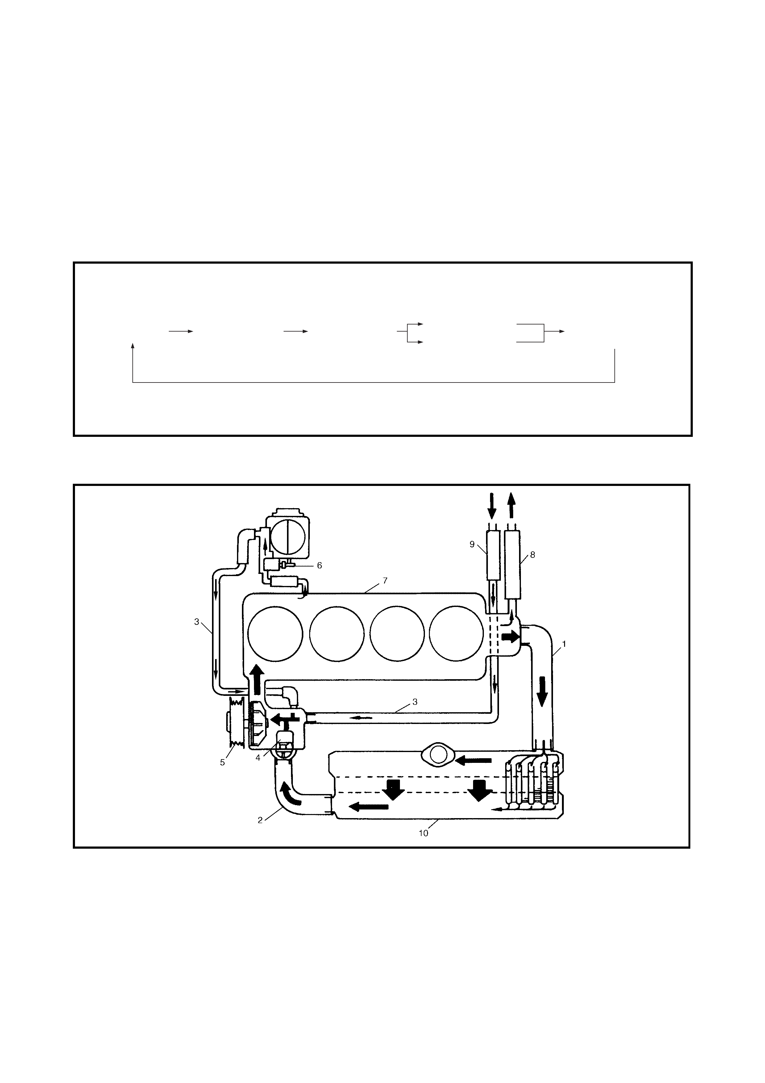
1.1 COOLING SYSTEM CIRCULATION
While the engine is warmed up (thermostat closed), coolant circulates as follows.
When coolant is warmed up to normal temperature and the thermostat opens, coolant passes through the
radiator core to be cooled as well as the above flow circuit.
Legend
Water pump Cylinder block
Thermostat closed
Cylinder head Water intake pipe
Throttle body
Heater unit
1. Radiator inlet hose 5. Water pump 8. Heater inlet hose
2. Radiator outlet hose 6. Throttle body 9. Heater outlet hose
3. Water inlet pipe (Fast idle control plunger) 10. Radiator
4. Thermostat 7. Engine
1.2 COOLANT
The coolant recovery system is standard. As the coolant in the radiator expands with heat, the overflow is col-
lected in the reservoir.
When the system cools down, the coolant is drawn back into the radiator.
The co oling syste m has been fille d at the factor y with a quality coolant to ensur e protect ion against freez ing,
corros ion and loss of coolant f rom boiling . This shoul d be done even i f ambient tem peratures below freezin g
point are not expected.
NOTE:
• Always use the reco mmende d coo lant. A lcohol or me thanol base co ola nt or pla in wate r alone shoul d not
be used in the cooling system at any time as damage to cooling system could occur.
• A mixture o f 30% Holden Cruze Coolant part nu mber 92145591 mixed wi th 70% water should be main-
tained for the purpose of corrosion protection and lubrication.
TESTING COOLANT CONCENTRATION
1. To ensure the specified ethylene glycol concentration is maintained in the engine coolant, the coolant
concentration must be checked at the time or distance intervals outlined in the MY2002 YG Holden Cruze
Owner's Handbook. The cooling system should be at or close to ambient temperature.
2. Carefully remove the radiator pressure cap from the radiator and, while holding the rubber bulb squeezed,
insert nozzle of coolant tester hydrometer, Tool No. AU505 into coolant. Releasing the rubber bulb will
then draw sufficient coolant into the tester to float hydrometer bulb freely.
3. Hold tester at eye level and read scale on hydrometer bulb at coolant level.
4. The reading shows the percentage of Holden Cruze Coolant contained in the engine coolant.
5. The hydrometer reading should show 30% if the coolant concentration is correct.
6. If a reading of less than 30% is achieved, the cooling system requires topping up with Holden Cruze
Coolant (P/No. 92145591).
7. Drain sufficient quantity of coolant from cooling system to allow top-up with coolant additive, then add the
required amount of the correct additive. Reinstall pressure cap to the radiator.
8. Start and run the eng ine unt il nor mal op erating t emper ature is reached. This will all ow the ad ded co olant
to be distributed throughout the cooling system.
COOLANT PROPORTIONING TABLE
COOLANT CAPAC ITY
Minimum tempera ture °C –16 –36
Percentage of Holden Cruze
coolant (P/No. 92145591) to water %30 50
Volume of coolant concentrate
to water Litre 1.52/3.53 2.52/2.52
Engine radiator and heater 4.20 litr es
Reservo ir tank 0.85 litr es
Total 5 .05 litr es
2. DIAGNOSIS
2.1 DIAGNOSIS TABLE
Condition Possible Cause Correction
Engine overheats
(radiator fa n operates) Loose or broken water pump belt Adjust or replace.
Low coolant Check coolant level and add as
necessary.
Faulty thermostat Replace.
Faulty water pump Replace.
Dirty or bent radiator fins Clean or remedy.
Coolant leakage from cooling system Repair.
Clogged radiator Check and replace radiator as
necessary.
Faulty radiator cap Replace.
Incor re ct igniti on tim ing Adjust .
Dragging brakes Adjust brake.
Slipping clutch Adjust or replace.
Poor battery charge Check and replace as necessary.
Faulty generator Check and repair.
ECT sensor faulty Check and replace as necessary.
Radiator cooling fan relay No.2 and / or No.3
faulty Check and replace as necessary.
ECM faulty Check and replace as necessary.
Wiring or grounding faulty Repair and necessary.
Electric load too high Reduce load.
Radiator cooling fan motor faulty Check and replace as necessary.
Engine overheats
(radiator fan does
not operate)
Fuse blown Check “RADTR fan” fuse and
check for short circuit to ground.
Radiator cooling fan relay No.1 Check and replace as necessary.
ECT sensor faulty Check and replace as necessary.
Radiator cooling fan motor faulty Check and replace as necessary.
Wiring or grounding faulty Repair as necessary
ECM faulty Check and replace as necessary.
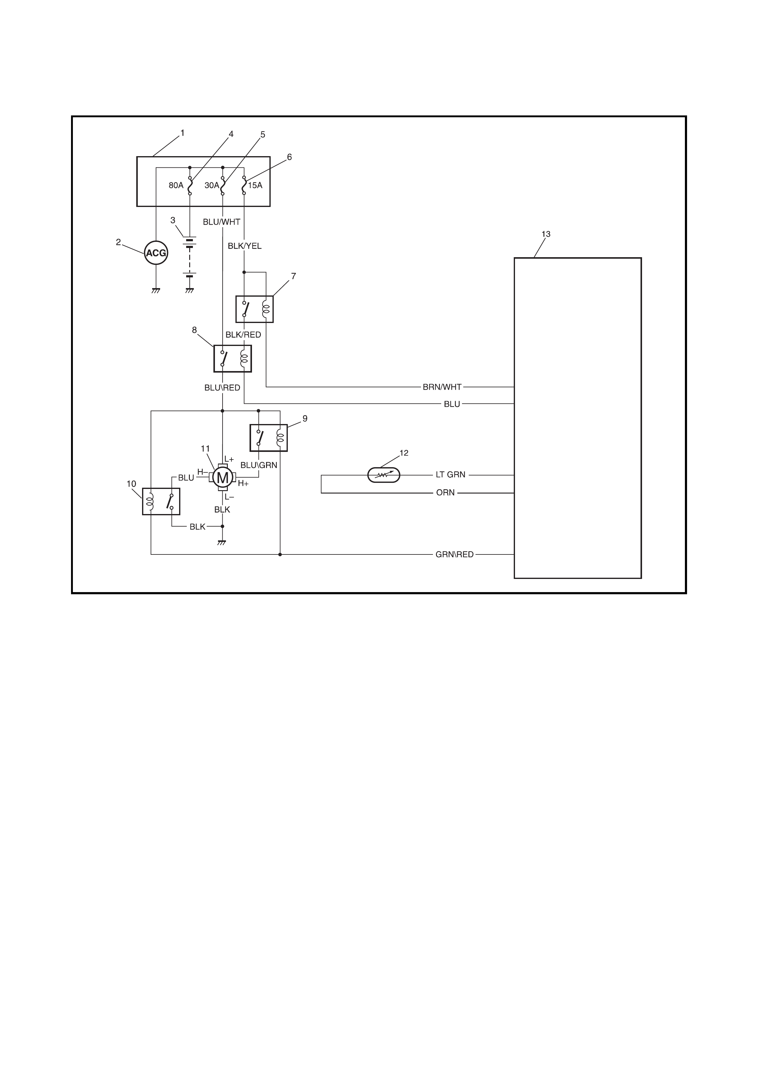
2.2 SYSTEM CIRCUIT
Legend
2.3 SYSTEM CIRCUIT INSPECTION
Refer to Section 6, 2.30 TABLE B-7 RADIATOR COOLING FAN CONTROL SYSTEM CHECK.
1. Main fuse box 6. ECM main fuse 11. Radiator cooling fan motor
2. Generator 7. ECM main relay 12. ECT sensor
3. Battery 8. Radiator cooling fan relay No.1 13. ECM
4. Battery fuse 9. Radiator cooling fan relay No.2
5. RADTR fuse 10. Radiator cooling fan relay No.3
3. MAINTENANCE
WARNING:
• Do not remove the radiator cap to check the engine coolant level; check the coolant visually at the
see-through coolant reservoir.
Coolant should be added only to the reservoir as necessary.
• While there is pressure within the cooling system, the coolant temperature can be considerably
higher as the boiling point is increased. Removal of the radiator cap while the engine is hot and
pressurised will caus e the solution to boil instantaneously, causing the solution to discharge with
explosive force over the vehicle and person removing cap. Although not recommended, if the
solution were to contain flammable anti-freeze such as alcohol, there is also the possibility of fire.
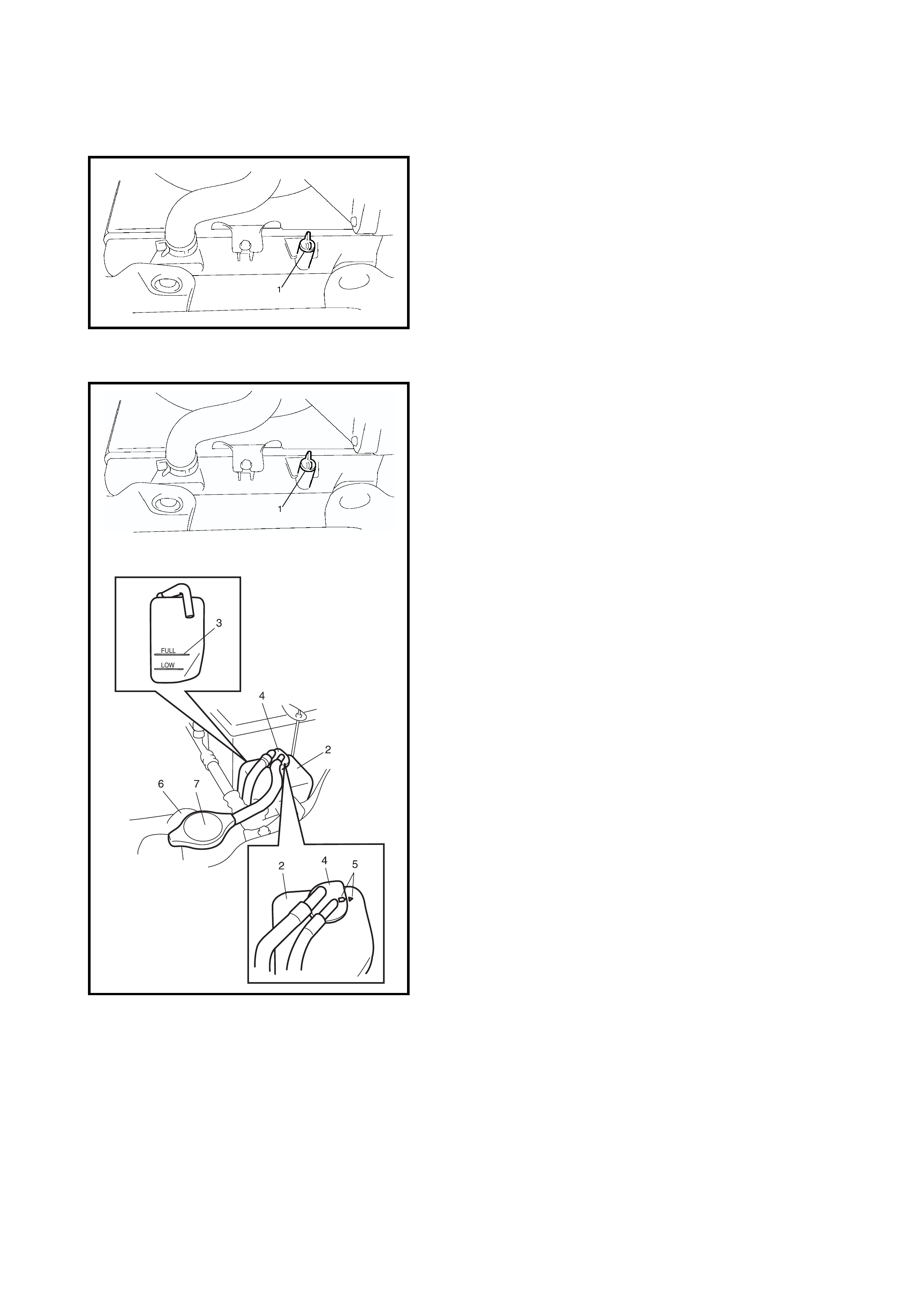
3.1 COOLANT LEVEL CHECK
To check the level, lift the hood and look at the “see-
through” coolant reservoir tank.
It is not neces sary to rem ove r adiato r cap to ch eck co ola nt
level.
WARNING:
To help avoid danger of being burned
• Do not remove the reservoir tank cap while coolant
is boiling, and
• Do not remove the radiator cap while the engine
and radiator are still hot.
• Scalding fluid and steam can be blown out under
pressure i f eith er cap is r emoved while t he coolin g
system is hot.
When the engine is cool, check the coolant level in the res-
ervoir tank (1).
A normal coolant level should be between the FULL (2) and
LOW (3) marks on the reservoir tank (1).
If the cool ant level is below the LOW ma rk (3), remo ve the
reservoir tank cap (4) and add the specified coolant to the
tank to bring the coolant level up to the FULL mark (2).
Then re ins tall th e c ap (4) and al ig n th e m atc h m arks (5) o n
tank and cap (4).
NOTE:
• If the specified antifreeze is used, there is no need to
further ad d inhibitors or addit ives that clai m to improve
the system per for ma nce.
They may be harmful to the proper operation of the
system and are an unnecessary expense.
• When installing the reservoir cap, align the arrow
marks on the reservoir and cap.
LOW
FULL
5
4
1
1
3
2
1
3.2 ENGINE COOLING SYSTEM INSPECTION AND SERVICE
WARNING:
• To avoid the danger of being burned, do not
remove the rad iator cap while the engine an d radia-
tor are still hot.
• Scalding fluid and steam can be blown out under
pressure if the cap is removed while the engine is
hot.
1. Check the cooling system for leakage or damage.
2. Wash the radiator cap and filler neck with clean water
by removing the radiator cap when the engine is cold.
3. Check the coolant for proper level and freeze protec-
tion.
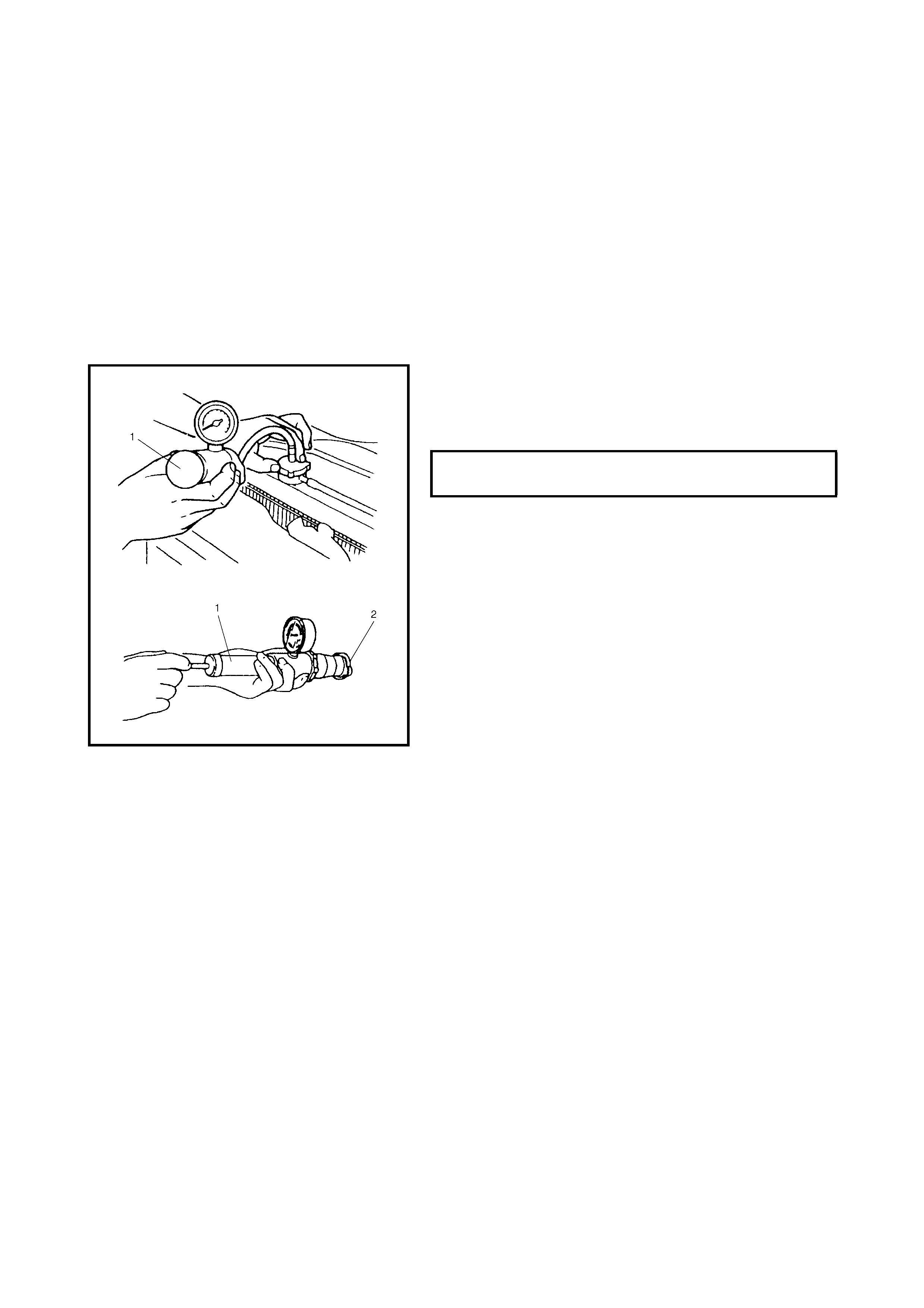
4. Using a pressure tester (1), check the system and
radiator cap (2) for proper pressure holding capacity.
If replaceme nt of the ca p is re quired, u se a prop er ca p
for this vehicle.
NOTE: After installing the radiator cap onto the radiator,
make sur e th at the ears of the c ap a re parall el t o the rad ia-
tor.
5. Tighten the hose clamps and inspect all hoses.
Replace hoses whenever cracked, swollen or
otherwise deteriorated.
6. Clean the frontal area of radiator core.
COOLING SYSTEM AND RADIATOR
CAP HOLDING PRESSURE 110 kPa
3.3 COOLING SYSTEM FLUSH AND REFILL
1. Remove the radiator cap when engine is cool.
a. Turn the cap counterclockwise slowly until it
reaches a “stop”. (Do not press down while
turning it).
b. Wait until pressure is relieved (indicated by a hiss-
ing sound) then press down on the cap and con-
tinue to turn it counterclockwise.
WARNING:
To avoid the danger of being burned, do not remove
the radiator cap while the engine and radiator are still
hot.
Scalding fluid and steam can be blown out under pres-
sure if the cap is removed while the engine is hot.
3. With the radiator cap removed, run the engine until the
upper radiator hose is hot (this shows that the thermo-
stat is open and coolant is flowing through the system).
4. Stop the engine and drain the coolant.
5. Close the drain plug. Add water until the system is filled
and run the engine until the upper radiator hose is hot
again.
6. Repeat Steps 3 and 4 several times until drained liquid
is nearly colourless.
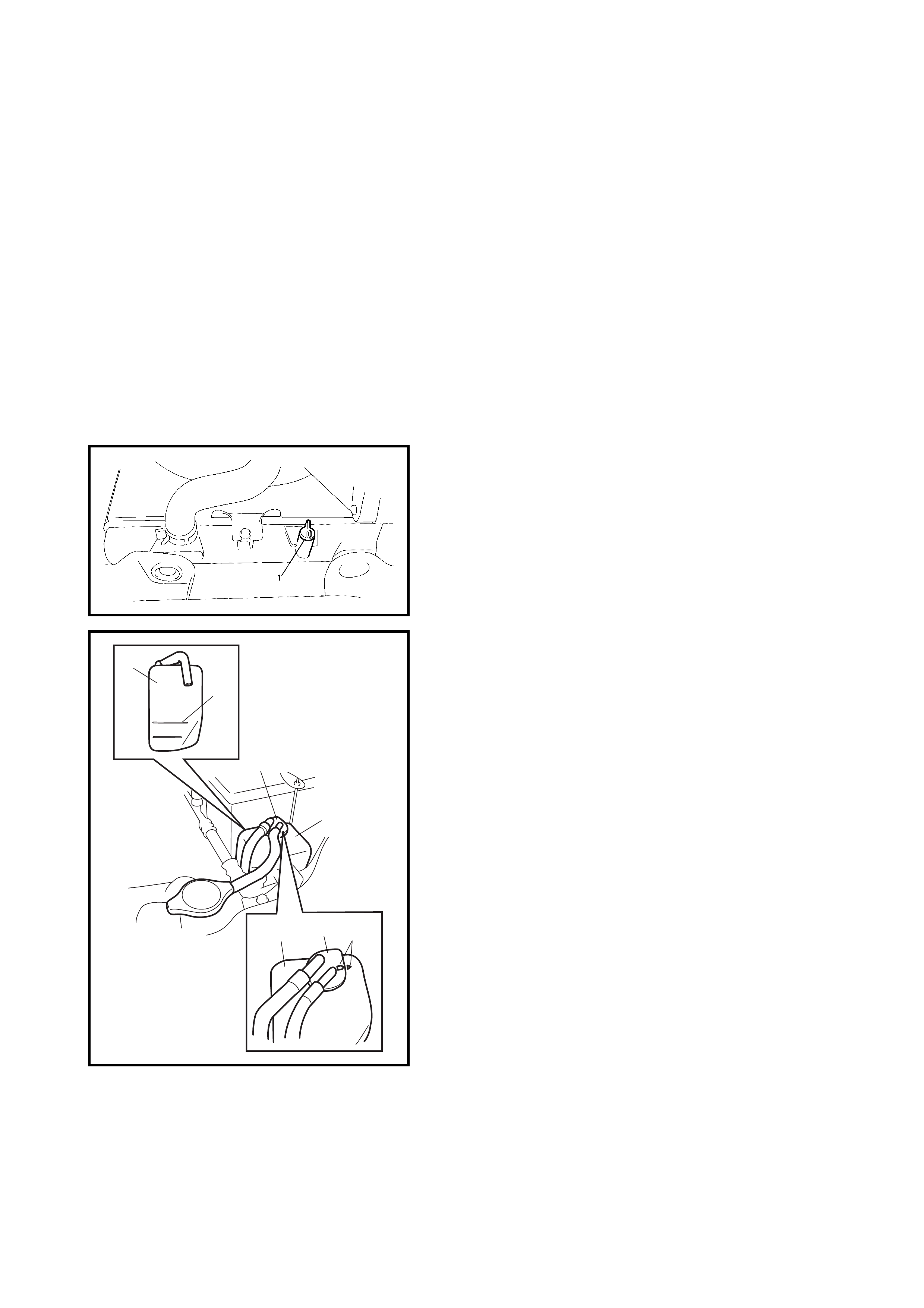
7. Drain the system and then close the radiator drain plug
(1) tightly.
8. Remove the reservoir tank (1), remove the cap (2) from
the reservoir tank (1) and pour out any fluid.
9. Scrub and clean the inside of the tank with soap and
water.
Flush it well with clean water and drain. Reinstall tank.
10. Add the specified coolant to the radiator and reservoir
tank. Refer to 1.2 COOLANT in this Section for coolant
concentration.
Fill the radiator to the bottom of the filler neck and the
reservoir tank to the FULL level mark (3).
11. Reinstall the reservoir tank cap and align the match
marks (4) on reservoir tank and its cap.
12. Run the engine with the radiator cap removed, until the
radiator inlet hose is hot.
13. With the eng ine idling, ad d coolant to the radi ator until
the level reaches the bottom of the filler neck. Install
the radiator cap, making sure that the ears of the cap
are parallel to the radiator.
LOW
FULL
4
1
1
3
2
2
1
3.4 WATER PUMP / GENERATOR DRIVE BELT TENSION INSPECTION AND
ADJUSTMENT
WARNING:
• Disconnect the negative cable at the battery before checking and adjusting belt tension.
• To avoid danger of being burned, do not remove the radiator cap while the engine and radiator are
still hot. Scalding fluid and steam can be blown out under pressure if the cap is removed while the
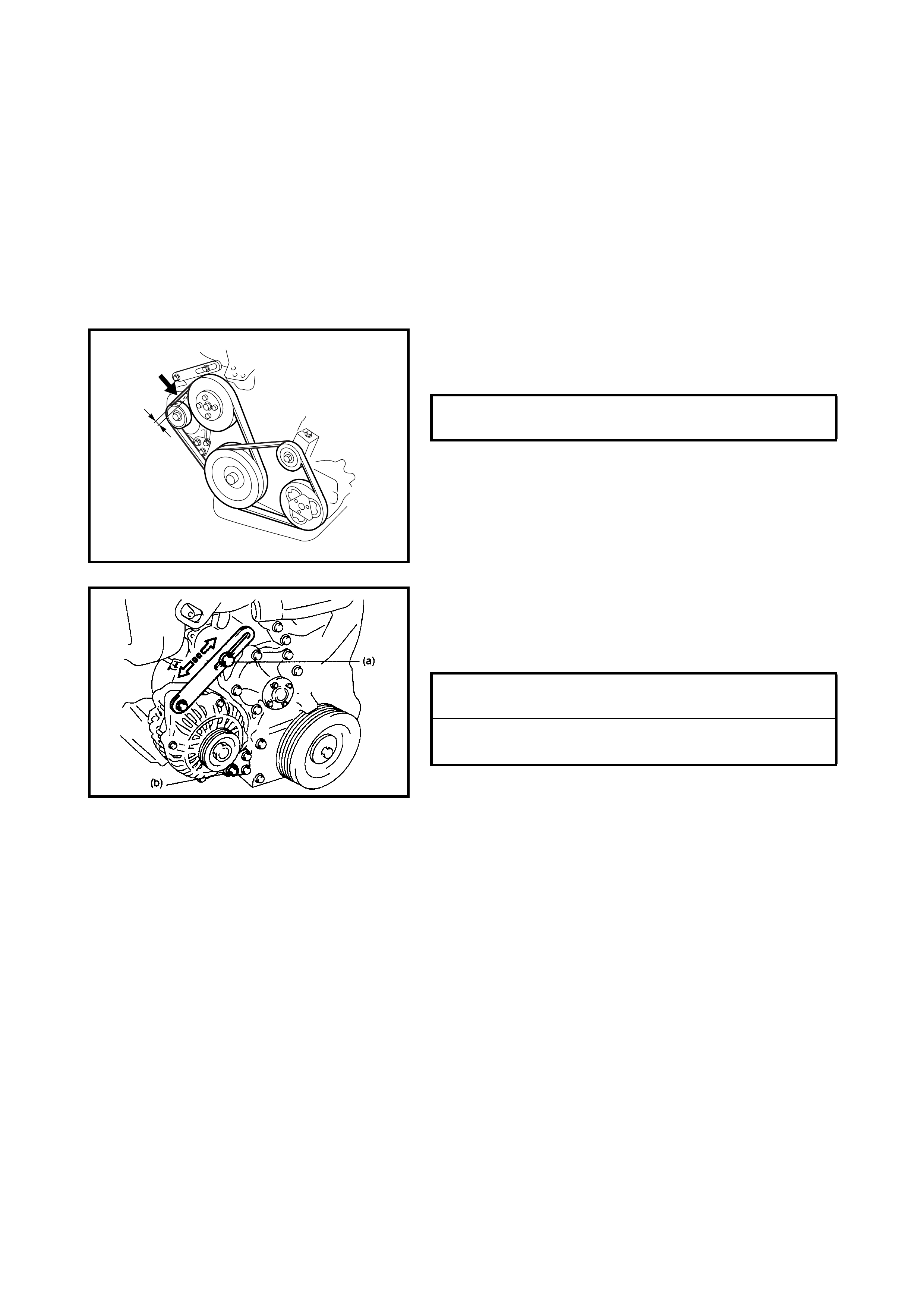
engine is hot. 1. Inspect the belt for cracks, cuts, deformation, wear and
cleanliness. If it is necessary to replace the belt, refer
to 4.9 WATER PUMP / GENERATOR DRIVE BELT in
this Section.
2. Check the belt for tension. Belt is in proper tension
when it deflects 4.5 to 5.5 mm under thumb pressure of
approximately 10 kg.
NOTE: When rep lac ing t he b el t wi th a ne w on e, a dju st bel t
tension to 3 - 4 mm.
3. If the belt is too tight or too loose, adjust it to the proper
tension by adjusting the generator position.
4. Tighten the generator adjusting bolt and pivot bolts to
the specifi ed torque.
WATER PUMP/GENERATOR DRIVE
BELT TENSION 4.5 - 5.5 mm @
10 kg
“a”
GENERATOR ADJUSTING BOLT (a)
TORQUE SPECIFICATION 23 Nm
GENERATO R PIVOT BOLT
TORQUE SPECIFICATION 50 Nm
4. ON-VEHICLE SERVICE
WARNING:
• Ensure the engine coolant temperature is cold before removing any part of cooling system.
• Disconnect the negative lead from the battery terminal before removing any parts.
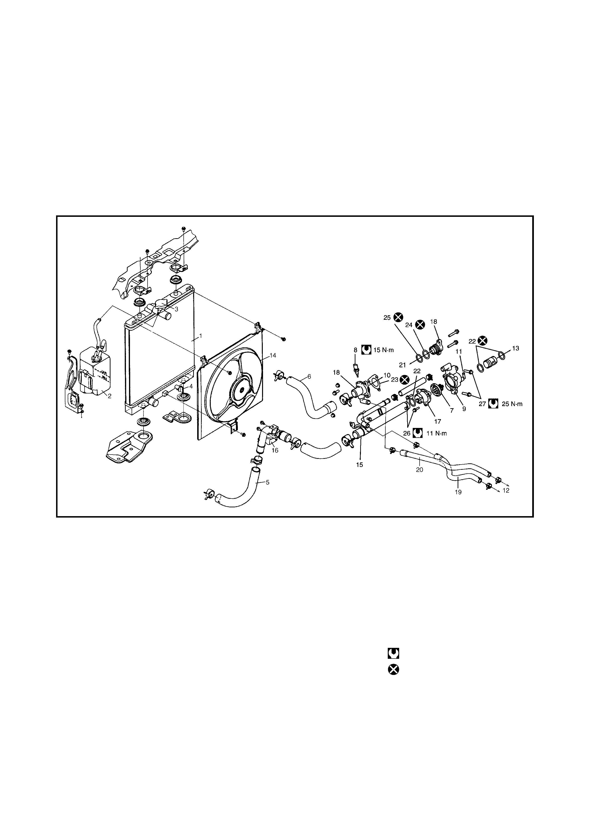
4.1 SYSTEM COMPONENTS
Legend
1. Radiator 11. To throttle body 20. Heater outlet hose
2. Reservoir tank 12. To heater unit 21. To timing chain cover
3. Radiator cap 13. To water pump 22. O-Ring
4. Drain plug 14. Radi ato r co oling fan
assembly 23. Gasket
5. Radiator outlet hose 24. Water outlet cap O-ring No.1
6. Radiator inlet hose 15. Water inlet pipe No.1 25. Water outlet cap O-ring No.2
7. Thermostat 16. Water inlet pipe No.2 26. Thermostat cap bolts
8. ECT sensor 17. Thermostat cap 27. Thermostat case bolts
9. Thermostat case 18. Water outlet cap Tightening torque
10. To cylinder head 19. Heater inlet hose Do not reuse.
4.2 COOLING SYSTEM DRAINING
1. Remove the radiator cap.
2. Loosen the radiator drain plug (1) to drain coolant.
3. After draining coolant, be sure to tighten drain plug
securely.
4.3 COOLING SYSTEM REFILL
1. Tighten the drain plug (1) securely.
2. Add the specified coolant to the radiator and reservoir
tank (2). For coolant concentration, refer to
1.2 COOLANT in this Section.
Fill the radiator to the bottom of filler neck and reservoir
tank (2) to the FULL level mark (3).
3. Reinstall the reservoir tank cap (4) and align match
marks (5) on the reservoir tank (2) and its tank cap (4).
4. Run the engine wi th t he ra dia tor c ap ( 7) r emo ve d, u nti l
the radiator inlet hose (6) is hot.
5. With the engine idling, add co olant to the radiato r unti l
the level reaches the bottom of the filler neck.
6. Install the radiator cap (7). Ensure the ears of the
radiator cap (7) are parallel to the radiator.
4.4 COOLING WATER PIPES OR HOSES
REMOVAL
1. Drain the cooling system.
2. To remove the pipes or hoses, loosen the clamp on
each hose and pull hose off.
INSTALLATION
Install removed parts in reverse order of removal proce-
dure, noting the following.
• Tighten each clamp securely.
• Refill the cooling system with specified coolant, refer to
4.3, COOLING SYSTEM REFILL in this Section.
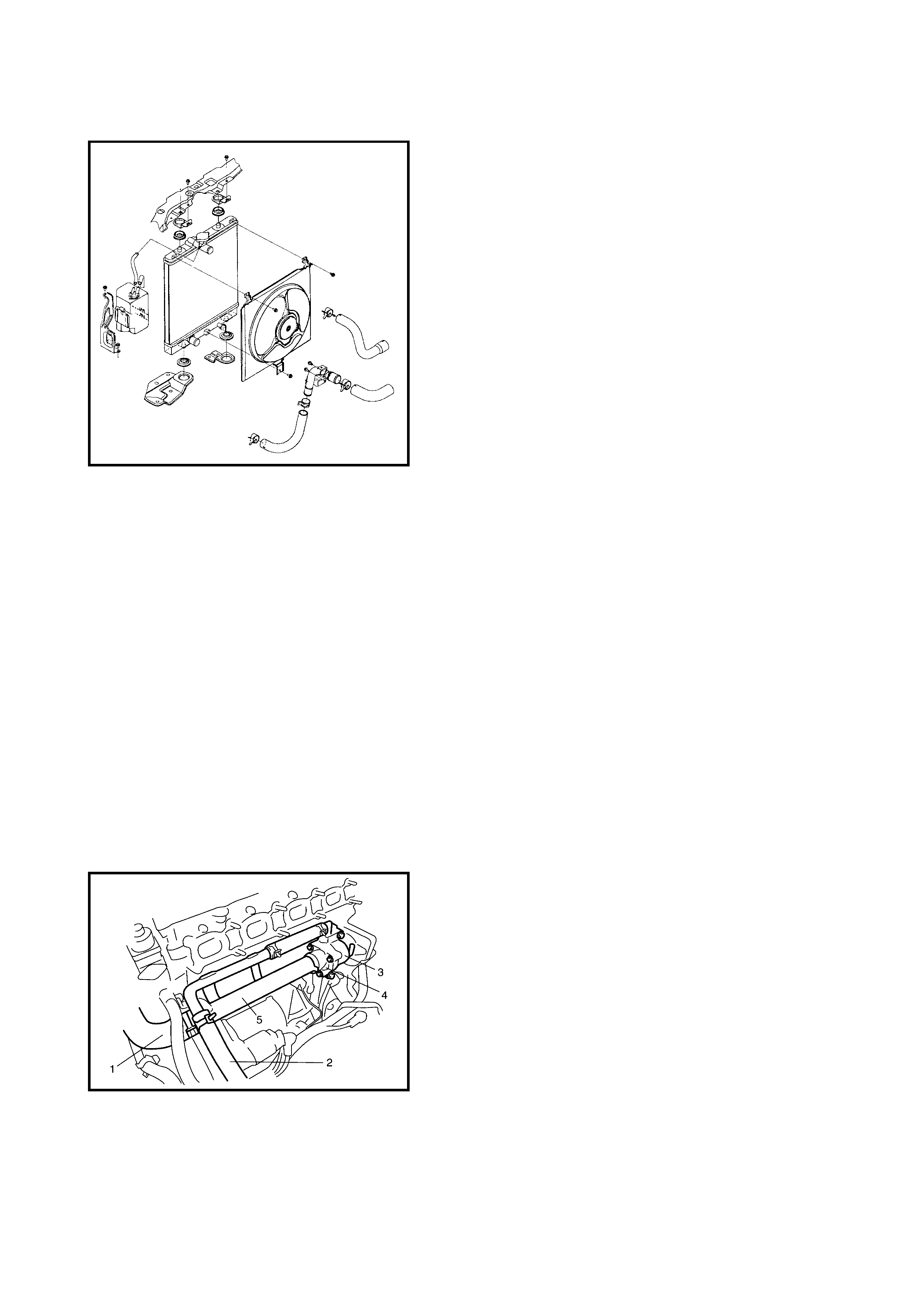
4.5 THERMOSTAT
REMOVAL
1. Drain the cooling system by loosening the drain plug of
radiator, refer to 4.2 COOLING SYSTEM DRAINING in
this Section.
2. Remove the air cleaner assembly and resonator, refer
to Section 6A1, 3.2 AIR CLEANER ASSEMBLY AND
RESONATOR.
3. Remove the intake manifold, refer to Section 6A1,
3.5 THROTTLE BODY AND INTAKE MANIFOLD.
4. Remove the generator, refer to Section 6H,
3.3 GENERATOR.
5. Disconnect the water hose (1) and heater hose (2)
from each pipe.
6. Remove the thermostat case (3) with the thermostat
cap (4) and water inlet pipe (5).
7. Remove the water inlet pipe with the thermostat cap
from the thermostat case.
8. Remove the thermostat.
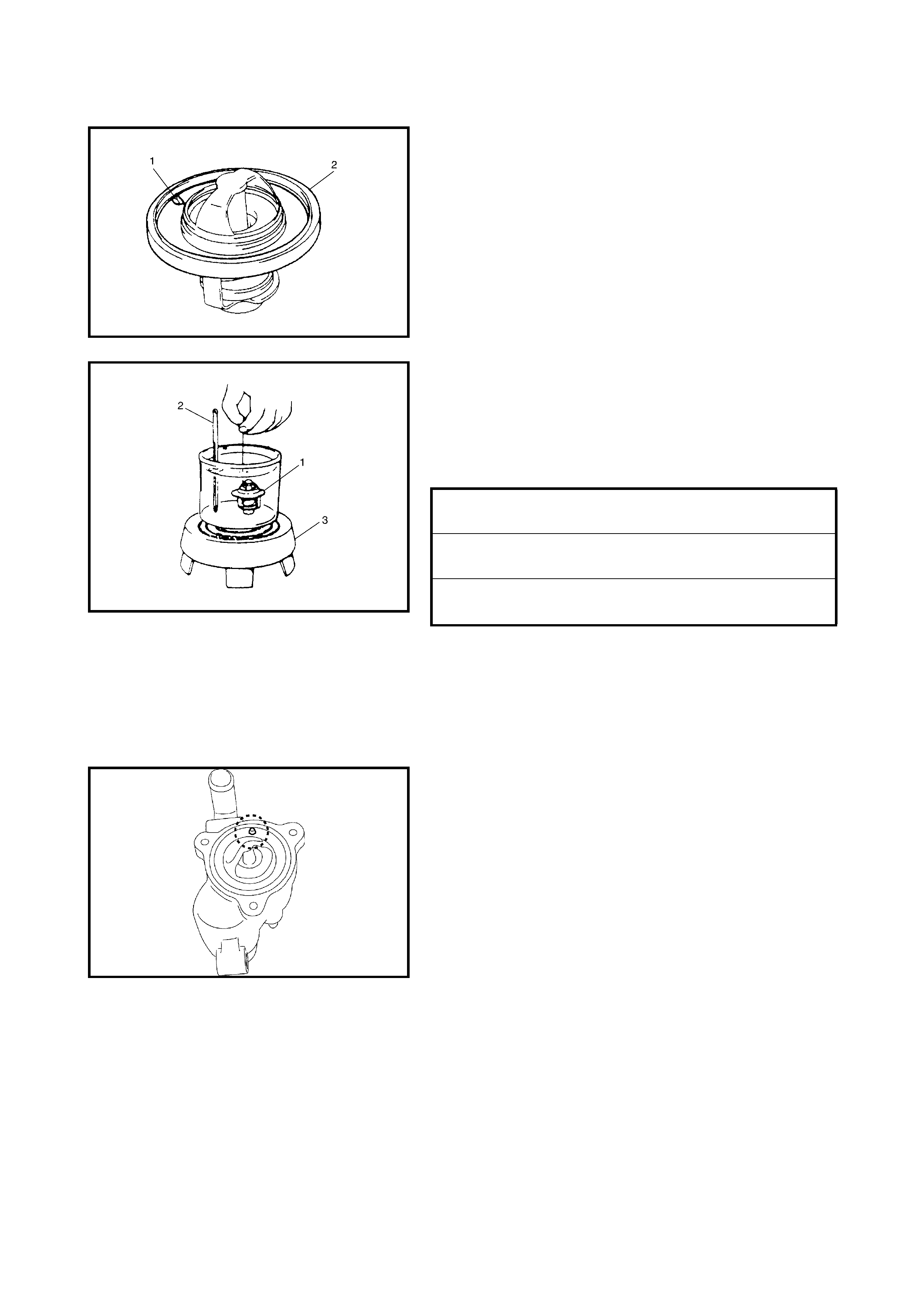
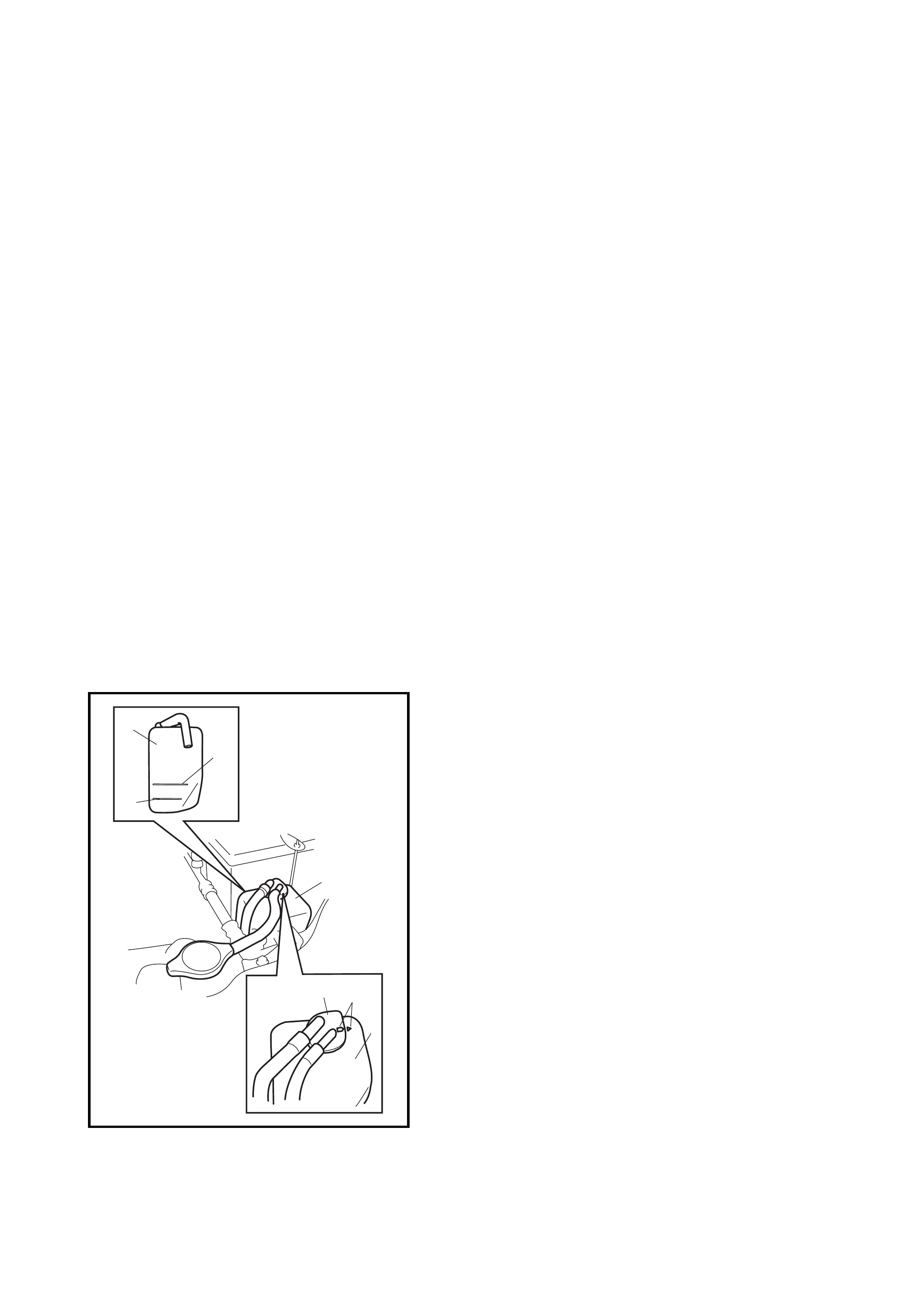
INSPECTION
• Make sure that the thermostat air bleed valve (1) is
clean.
Should this valve be clogged, the engine would tend to
overheat.
• Check to make sure that the valve seat is free from for-
eign materials which would prevent the valve from
seating tight.
• Check the thermostat seal (2) for breakage, deteriora-
tion or any other damage.
• Check the thermostatic movement of the wax pellet as
follows:
a. Immerse the thermostat (1) and a thermometer (2)
in water, and heat the water gradually (3).
a. Check that the valve starts to open at specific
temperature.
If the valve starts to open at a temperature substantially
below or above the specified temperature, the thermostat
unit should be replaced with a new one.
INSTALLATION
Reverse removal procedure for installation noting the
following:
• When positioning the thermostat (1) on the thermostat
case (2). Position it so that the air bleed valve (3)
aligns at the position as shown.
• Use new O-rings when installing.
• Adjust the water pump belt tension, refer to
3.4 WATER PUMP / GENERATOR DRIVE BELT
TENSION INSPECTION AND ADJUSTMENT in this
Section.
• Adjust the A/C compressor belt tension (if equipped),
refer to Section 1B, 2.5 COMPRESSOR DRIVE BELT.
• Refill the cooling system with the specified coolant,
refer to 4.3, COOLING SYSTEM REFILL in this
Section.
• Verify that there is no coolant leakage at each
connection.
TEMPERATURE AT WHICH VALVE
BEGINS TO OPEN 80 - 84°C
TEMPERATURE AT WHICH VALVE
BECOMES FULLY OPEN 95 - 97°C
VALVE LIFT More than 8 mm
@ 95°C
4.6 RADIATOR
REMOVAL
1. Disconnect the negative cable at battery.
2. Drain the cooling system by loosening the radiator
drain plug, refer to 4.2 COOLING SYSTEM DRAINING
in this Section.
3. Disconnect the connector of the cooling fan motor.
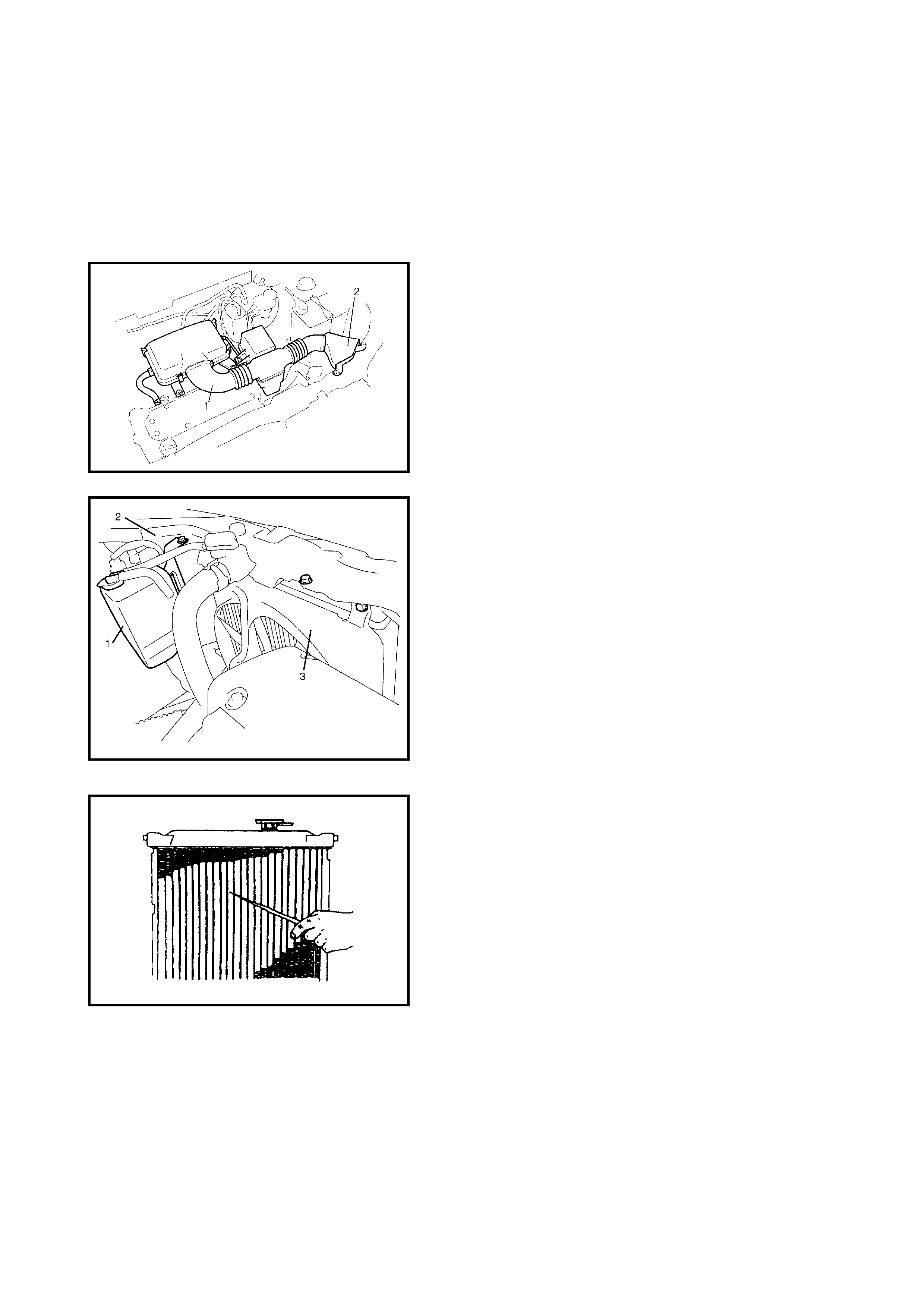
4. Remove the air cleaner inlet hose (1) and suction pipe
(2).
5. Remove the reservoir tank (1) and its bracket (2).
6. Disconnect the radiator inlet and outlet hoses from the
radiator.
7. Remove the A/C suction hose clamp bolt, if fitted.
8. For auto transmission models, detach the select cable
bracket from the transmission.
9. Remove the radiator brackets and then remove the
cooling fan assembly (3).
10. Remove the radiator.
INSPECTION
Check the radiator for leakage or damage. Straighten any
bent fins.
CLEANING
Clean the frontal area of the radiator core.
INSTALLATION
Reverse removal procedures, noting the following:
• Refill the cooling system with specified coolant, refer to
4.3 COOLING SYSTEM REFILL in this Section.
• After installation, check each joint for leakage.
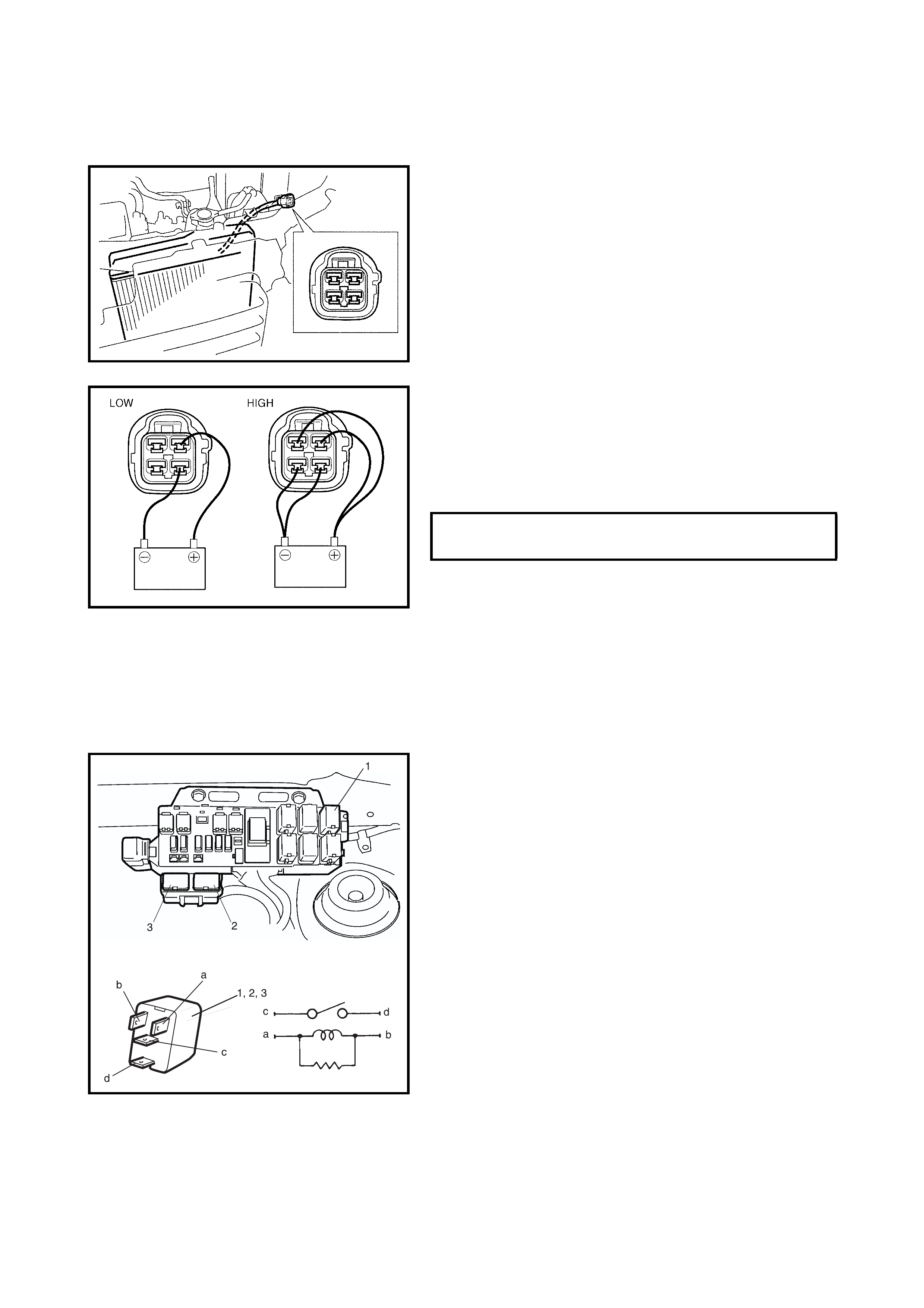
4.7 RADIATOR COOLING FAN
INSPECTION
1. Check for continuity between each terminal.
If no continuity exists, replace the radiator fan motor.
2. Connect the battery to the radiator fan motor connector
as shown, then check that the radiator fan motor
operates smoothly, the fan speed varies and at the
specified current.
If the fan motor does not meet the specified conditions,
replace the motor.
REMOVAL / INSTALLATION
Refer to 4.6 RADIATOR in this Section.
4.8 RADIATOR COOLING FAN RELAY
INSPECTION
1. Disconnect the negati ve (–) ca ble at battery.
2. Remove the radiator cooling fan relay No.1 (1), No.2
(2) and No.3 (3) from the vehicle.
3. Check that there is no continuity between terminal “c”
and “d”.
If continuity exists, replace relay.
4. Connect battery positive (+) to terminal “b” of relay.
Connect battery negative (–) to terminal “a” of relay.
Check continuity between terminals “c” and “d”.
If there is no continuity wh en the relay i s connected to
the battery, replace the relay.
RADIATOR COO LING FAN MOTOR
CURRENT @ 12v LOW 8.8 A max.
HIGH 11.8 A max.
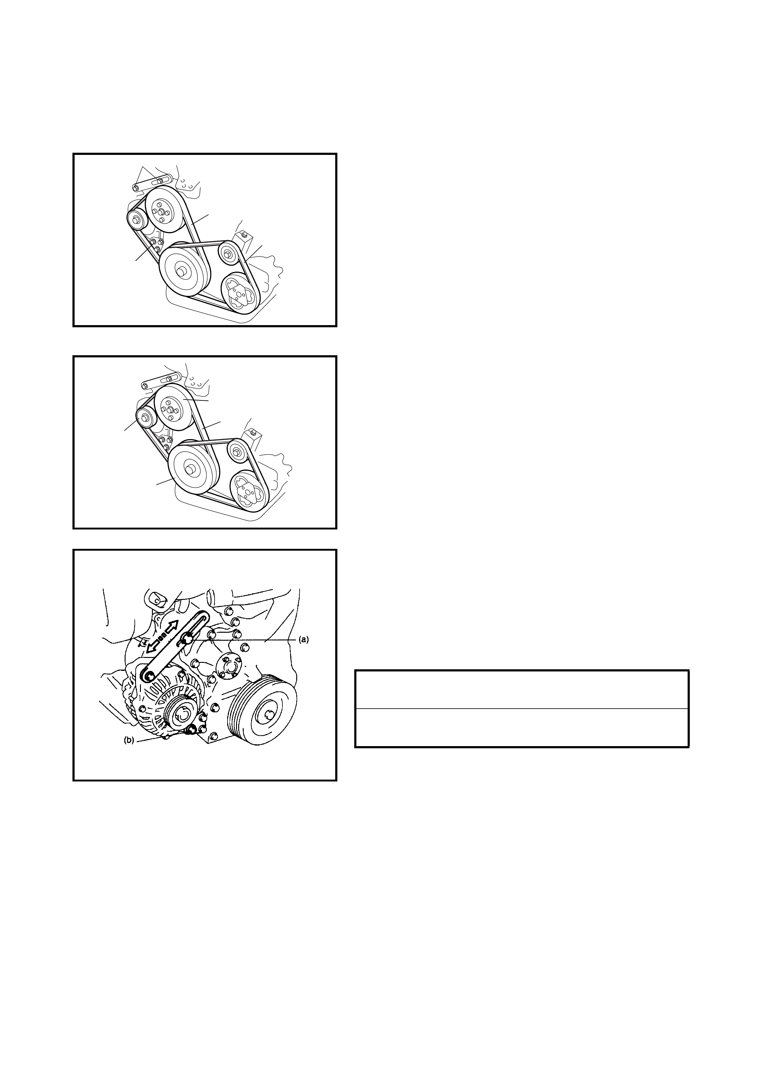
4.9 WATER PUMP / GENERATOR DRIVE BELT
REMOVAL
1. Disconnect the negative cable at battery.
2. Loosen the drive belt adjusting bolt (2) and generator
pivot bolt (3).
When servicing a car equipped with A/C, remove the
compressor drive belt (4) before removing the water
pump belt (1).
Refer to Section 1B, 2.5 COMPRESSOR DRIVE BELT.
3. Slacken the belt by moving the generator and then
remove the belt.
INSTALLATION
1. Install the belt (1) onto the water pump pulley (2),
crankshaft pulley (3) and the generator pulley (4).
When servicing a car equipped with A/C, install the
compressor drive belt.
2. Adjust the belt tension, refer to 3.4 WATER PUMP/
GENERATOR DRIVE BELT TENSION INSPECTION
AND ADJUSTMENT in this Section.
For adjustment of compressor drive belt tension, refer
to Section 1B, 2.5 COMPRESSOR DRIVE BELT.
3. Tighten wate r pump be lt ad justi ng bol t and pivot bol t to
specified torque.
4. Connect the negative cable at the battery.
WATER PUMP BELT TENSION INSPECTION AND
ADJUSTMENT
NOTE: For this inspection or adjustment, refer to
3.4 WATER PUMP / GENERATOR DRIVE BELT TENSION
INSPECTION AND ADJUSTMENT in this Section.
2
3
1
4
2
1
3
4
GENERATOR ADJUSTING BOLT (a)
TORQUE SPECIFICATION 23 Nm
GENERATOR PIVOT BOLT (b)
TORQUE SPECIFICATION 50 Nm
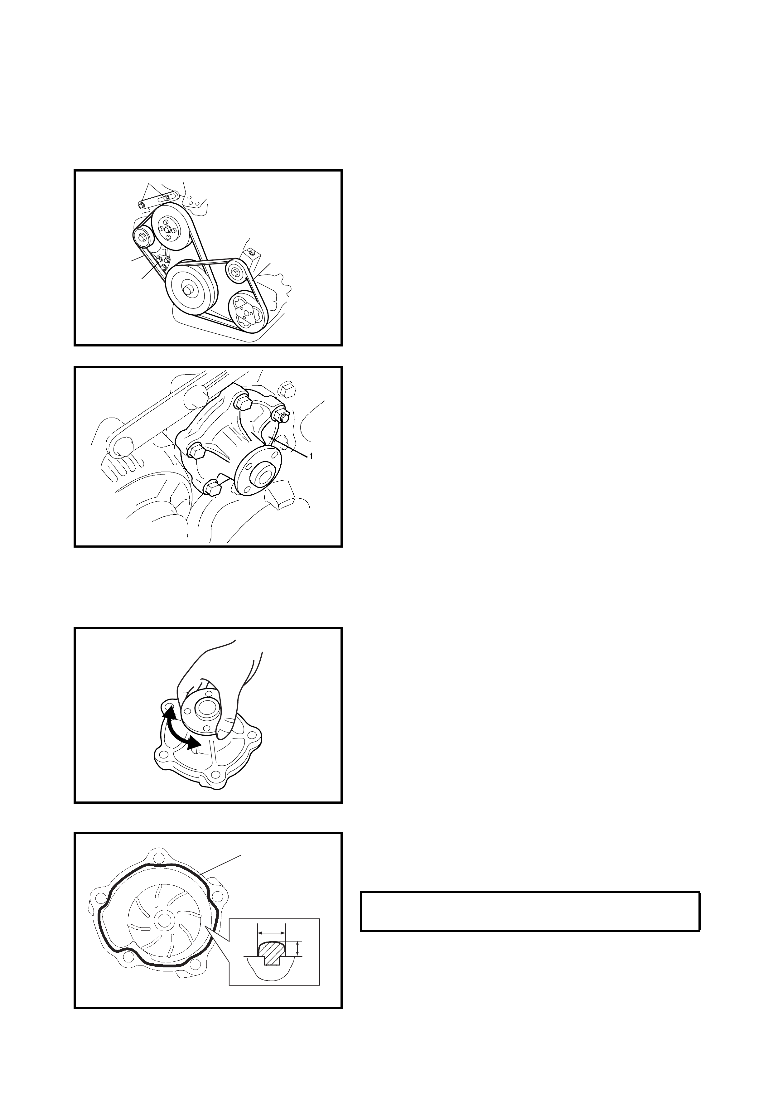
4.10 WATER PUMP
REMOVAL
1. Disconnect the negative cable at battery.
2. Drain the coolant, refer to 4.2 COOLING SYSTEM
DRAINING in this Section.
3. Remove the A/C compr essor belt (4 ) if e quippe d, refer
to Section 1B, 2.5 COMPRESSOR DRIVE BELT.
4. Loosen the wate r p ump / gener a tor dr ive b el t adj us tin g
bolt (1) and generator pivot bolt (2).
5. Remove the water pump / generator drive belt (3) and
water pump pulley.
Refer to 4.9 WATER PUMP / GENERATOR DRIVE
BELT in this Section.
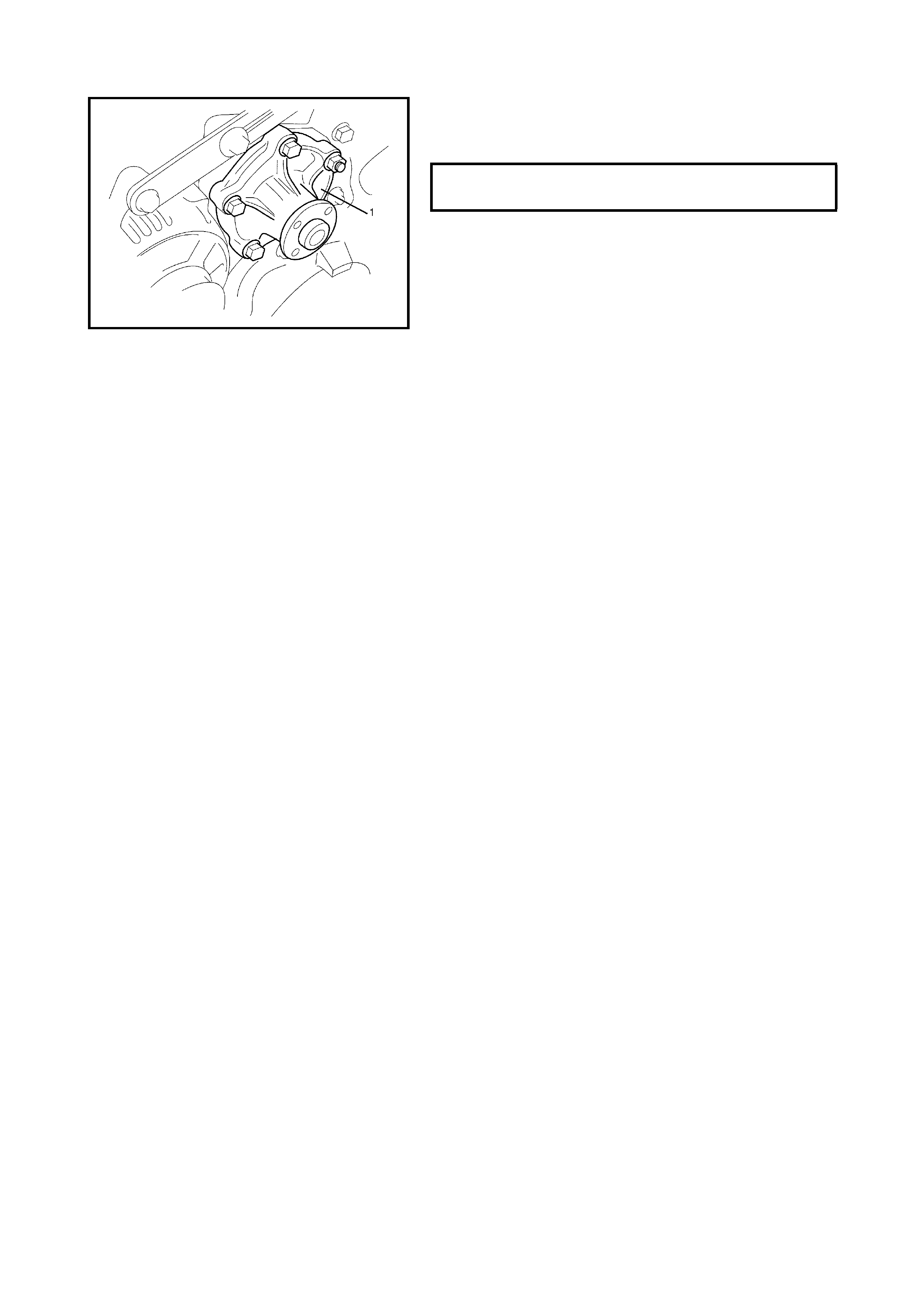
6. Remove the water pump assembly (1).
INSPECTION
CAUTION:
Do not disassemble the water pump. If repairs are
required to the pump, replace it as assembly.
• Rotate the water pump by hand to check for smooth
operation.
If the pump does not rotate smoothly or makes an
abnormal noise, replace it.
INSTALLATION
1. Apply sealant to the mating surface of the water pump
as shown.
(A): Sealant - Three Bond No. 1207C
1
2
4
3
SEALANT QUANTITY (TO MATING
SURRACE OF WATER PUMP) WIDTH (a) 3 mm
LENGTH (b) 2 mm
(a)
(A)
(b)
2. Install the water pump assembly (1) to the cylinder
block and tighten the bolts and nut to the specified
torque.
3. Install the water pump pulley.
4. Install the water pump / generator drive belt, refer to
4.9 WATER PUMP / GENERATOR DRIVE BELT in this
Section.
5. Install the A/C compressor belt (if equipped), refer to
Section 1B 2.5 COMPRESSOR DRIVE BELT.
6. Fill with coolant, refer to 4.3 COOLING SYSTEM
REFILL in this Section.
7. Connect the negative cable at the battery.
8. Check each part for leakage.
4.11 ECT SENSOR
Refer to 2.3, ELECTRONIC CONTROL SYSTEM,
ENGINE COOLANT TEMPERATURE SENSOR (ECT
SENSOR) in Section 6E1 ENGINE AND EMISSION
CONTROL SYSTEM.
WATER PUMP BOLTS AND NUT
TORQUE SPECIFICATION 22 Nm

5. REQUIRED SERVICE MATERIAL
Material
Recommended product
Use
Anti-freeze /Anti-corro-
sion coolant 30% Holden Cruze coolant part
number 92145591 Additive to engine cooling system for improv-
ing cooling efficiency and for protection
against rusting.
Sealant Three Bond No. 1207C To apply to mating surface of water pump