SECTION 6C - ENGINE FUEL
1. GENERAL DESCRIPTION
2. ON-VEHICLE SERVICE
2.1 COMPONENTS
2.2 PRECAUTIONS
2.3 FUEL LIN ES
Inspection
2.4 FUEL PIPE
Removal
Installation
2.5 FUEL FILL ER CA P
Inspection
2.6 FUEL TANK INLET VALVE
Removal
Inspection
Installation
2.7 FUEL TAN K
Removal
Inspection
Fuel Tank Purging Procedure
Installation
2.8 FUEL PUMP ASSEMBLY
Removal
Inspection
Disassembly and Reassembly
Installation
3. SPECIAL TOOLS
WARNING:
For vehicles equipped with Supplemental Restraint (Airbag) System:
• Service on and around the airbag system components or wiring must be performed only by
an authorised HOLDEN retailer. Refer to AIRBAG SYSTEM COMPONENTS and WIRING
LOCATION V IEW under GENERA L DESCRIP TION in Section 10B AIRBAG SYSTEM in order
to confirm whether you are performing service on or near the airbag system components or
wiring. Please observe all WARNINGS and SERVICE PRECAUTIONS under ON-VEHICLE
SER VI CE i n a irb ag sy st em s ecti on bef ore pe rfo rmi ng se rvi ce o n or aro un d th e air b ag sys t em
component s or wiring. Failure to follow W ARNINGS could result in unintentional activation of
the system or could render the system inoperative. Either of these two conditions may r esult
in severe injury.
• Technical service work must be started at least 90 seconds after the ignition switch is turned
to the “LOCK” position and the negative cable is disconnected from the battery. Otherwise,
the syst e m ma y be ac ti va ted by re se rv e e nerg y i n the S en si ng an d Di agno st i c Modu l e ( SDM ).
CAUTION:
The engine of this vehicle requires the use of unleaded fuel only. Use of leaded and/or low lead
fuel can result in engine damage and reduce the effect iveness of the emission con trol system.
1. GENERAL DESCRIPTION
The mai n components of the fue l system are fuel tank, fuel pum p assembly (wi th fuel filter, fuel lev el gauge,
fuel pressure regulator and tank pressure control valve), fuel/vapor separator fuel feed line and fuel vapor line.
For the details of fuel flow and fuel vapor flow, refer to Section 6E1 ENGINE AND EMISSION
CONTROL SYSTEM. - 2.2 FUEL DELIVERY SYSTEM
2. ON-VEHICLE SERVICE
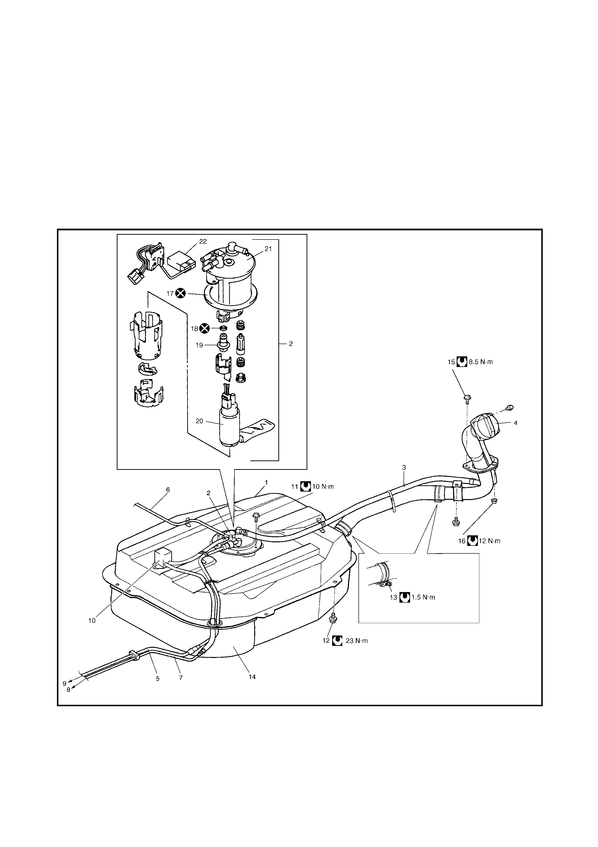
2.1 COMPONENTS
Legend

1. Fuel tank 8. EVAP canister 14. Tank cover 19. Fuel pressu re
regulator
2. F uel pump assem b ly 9. Del iv ery pip e 15. F ue l filler bracket
screw
3. Breather hose 10. Fuel/vapour
separator 20. Fuel pump
4. Fuel filler cap 16. Fuel filler bracket
nut 21. Fuel filter assembly
5. Fuel feed line 11. Fuel pump bolt 22. Fuel level gauge (Fuel
sender gauge)
6.
7.
Wire harness for fuel
pump
Fuel vapour line
12. Fuel tank bolts 17. Gasket
13. Fuel filler hose
clamp screw 18. O -r ing Do not reuse
Tightening torque
2.2 PRECAUTIONS
Warning: Before attempting service of any type on the fuel system, the following should always be
observed in order to reduce the risk of fire and personal injury.
• Disconnect negative cable at battery.
• Do not smoke, and place no smoking signs near work area.
• Be sure to have a CO
2
fire extinguisher handy.
• Be sure to perform work in a well-ventilated area and away from any open flames (such as gas
heater).
• Wear safety glasses.
• To relieve fuel vapour pressure in fuel tank, remove fuel filler cap from fuel filler neck and then
reinstall it.
• As the fuel feed line is under high pressure even after the engine has stopped, loosening or dis-
connecting the fuel feed line directly may cause a dangerous spurt of fuel to occur where loos-
ened or disconnected.
Before loosening or disconnecting the fuel feed line, make sure to relieve fuel pressure, refer to
Secti on 6, 1.4 FUEL PRESSURE RELIEF PROCEDURE.
• A small amount of fuel may be released after the fuel line is disconnected. In order to reduce the
chance of personal injury, cover the fitting to be disconnected with a cloth. Be sure to dispose of
cloth in an approved container when work is completed.
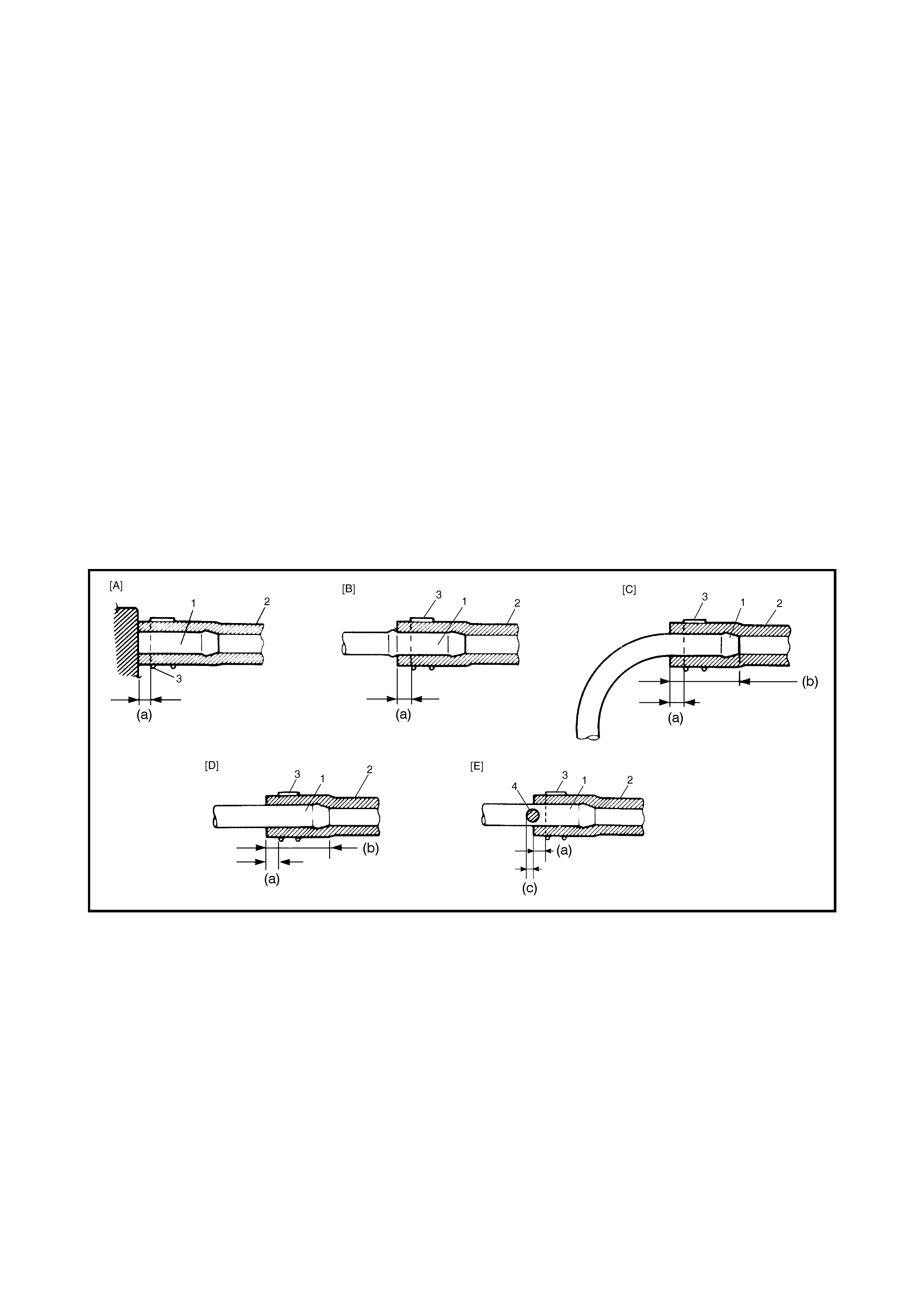
• Note that fuel hose connection varies with each type of pipe. Be sure to connect and clamp each
hose correctly referring to the figure.
Legend
[A]. On short pipe, fit hose fully [C]. On bent pipe, fit hose as 1. Pipe
to pipe joint as shown. far as its bent part as shown 2. Hose
or to depth (b). 3. Clamp
[B]. On this type of pipe, [D]. On straight pipe, fit hose 4. Red mark
fit hose as far as its to depth (b). (a). Clamp securely at a position
peripheral projection as [E]. On red marked pipe, fit hose 3 to 7 mm
shown. until hose end reaches red from hose end.
mark on pipe. (b). 20 to 30 mm
(c): 0 to 5 mm
2.3 FUEL LINES
CAUTION: Fuel feed line (1) is under high pressure,
use special care when servicing it.
INSPECTION
Visually inspect fuel lines for evidence of fuel leakage, hose
cracking and deterioration, or damage.
Make sure all clamps are secure.
Replace parts as needed.
2.4 FUEL PIPE
WARNING: A small amount of fuel may be released
af ter a fuel hose is disconnected. In order to reduce the
chance of personal injury, cover hose and pipe to be
disconnected with a cloth.
Be sure to dispose of cloth in an approved container
when work is completed.
REMOVAL
1. Relieve fuel pressure in fuel feed line, refer to
Section 6, 1.4 FUEL PRESSURE
RELIEF PROCEDURE.
2. Disconnect negative cable at battery.
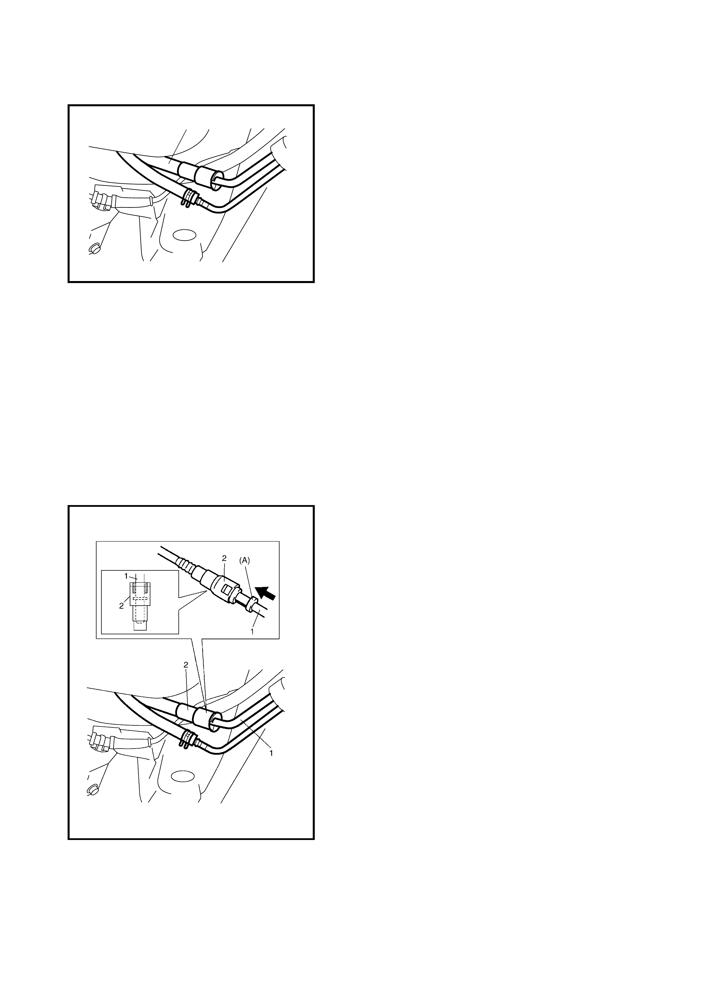
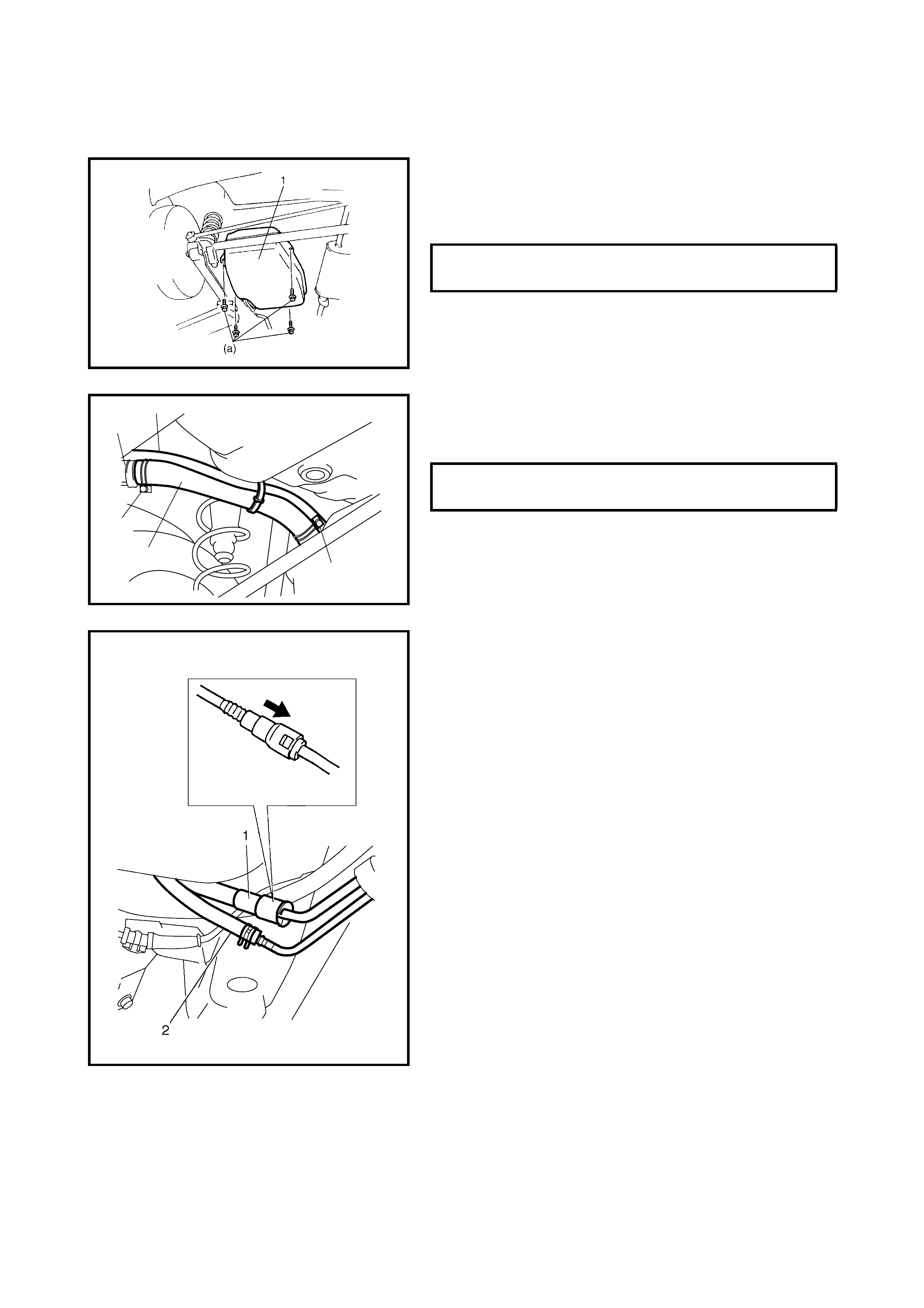
3. Disconnect fuel pipe joint and fuel hose from fuel pipe
at the front and rear of each fuel pipe.
For quick joint (2), disconnect as follows:
a. Remove mud, dust and/or foreign material between
pipe (1) and joint by blowing with compressed air.
b. Unlock joint lock by inserting special tool
09910-47020 between pipe and joint.
c. Disconnect joint (2) from pipe (1).
1
4. Mark the location of clamps (1) on fuel pipes (2), so
that the clamps ca n be rein stalled in the ir origi nal loc a-
tions.
5. Remove pipes (2) with clamp (1) from vehicle.
6. Remove clamp (1) from pipes (2).
INSTALLATION
1. Install clamps to the marked location on pipes. If clamp
is deformed or its claw is bent or broken, replace it with
a new one.
2. Install pipes with pipe clamps to vehicle.
3. Connect fuel hoses and pipes to each pipe.
CAUTION: When connecting joint, clean outside sur-
faces of pipe where joint is to be inserted, push joint
into pipe until joint lock clicks and check to ensure that
pipes are connected securely, or fuel leak may occur.
4. With engine OFF, turn ignition switch to ON position
and check for fuel leaks.
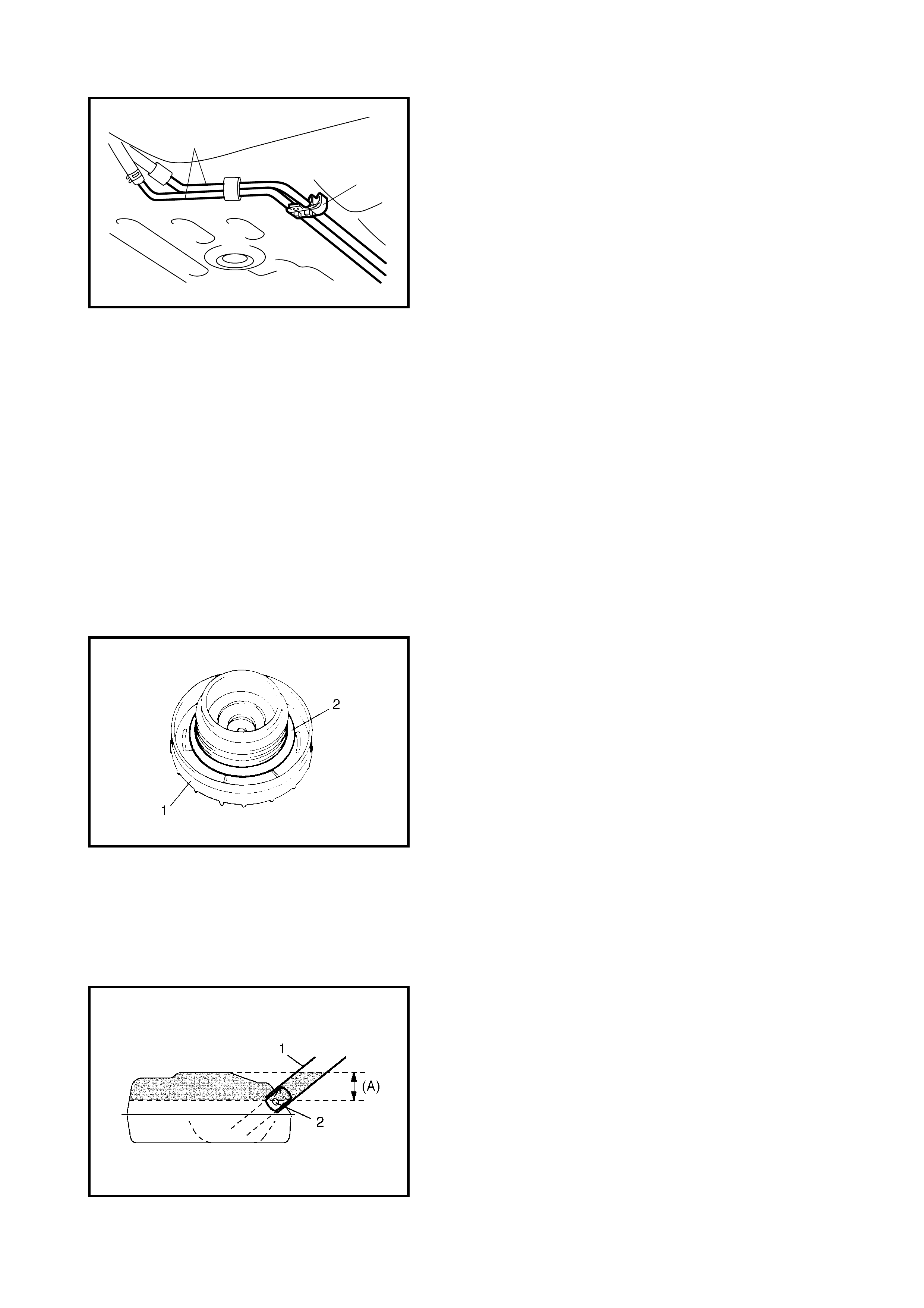
2.5 FUEL FILLER CAP
INSPECTION
Remove cap (1), and check gasket for even filler neck
imprint, deterioration or damage. If gasket (2) is damaged
or shows signs of deterioration, replace cap.
NOTE: If cap requires replacement, only a cap with the
same features should be used. Failure to use the correct
cap can result in critical malfunction of the system.
2.6 FUEL TANK INLET VALVE
WARNING: Refer to the WARNING at the beginning of
2.0 ON-VEHICLE SERVICE in this Section.
REMOVAL
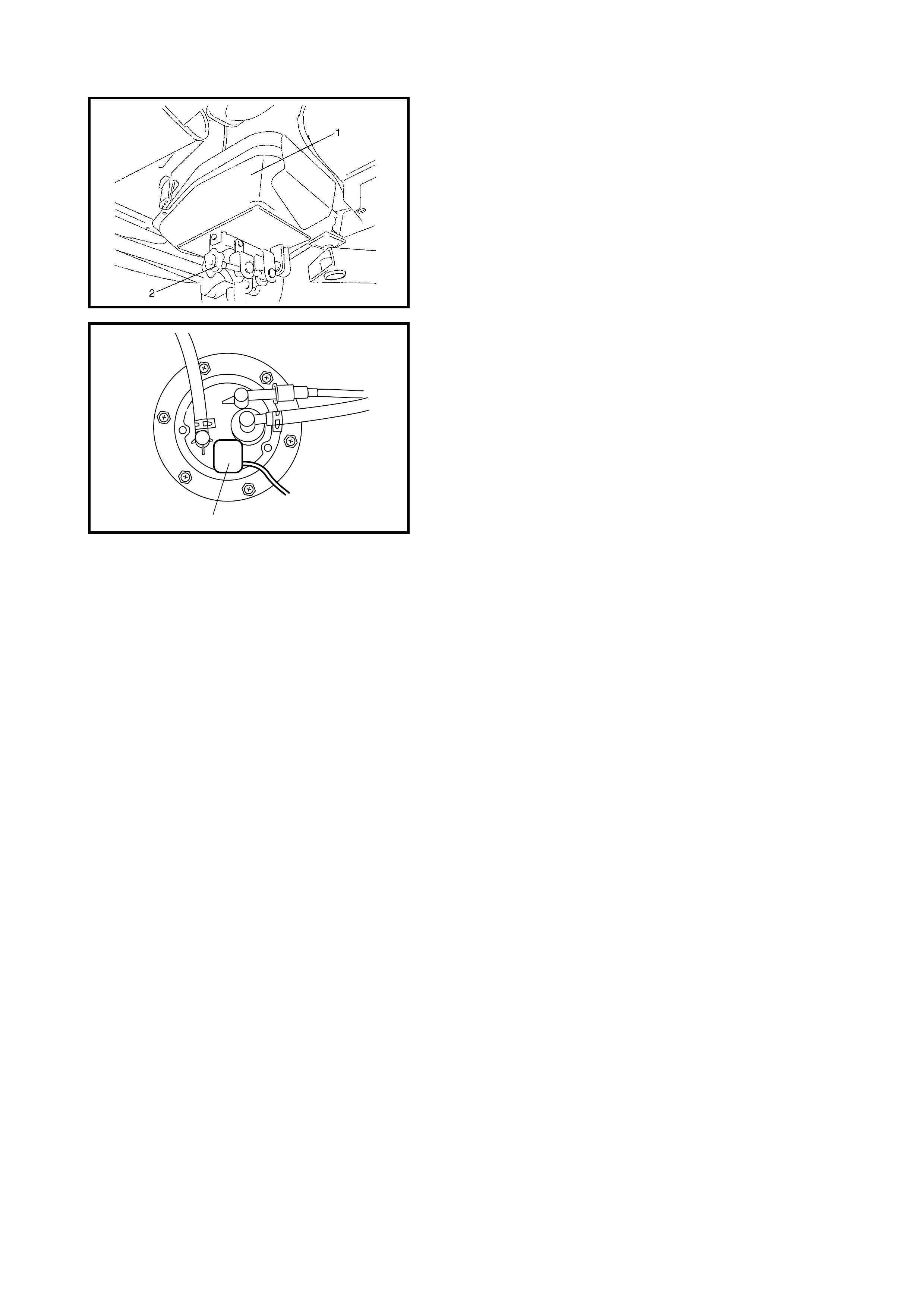
1. Remove fuel filler cap.
2. Feed hose of a hand operated pump into the fuel filler
hose (1) and drain fuel in space (A) as shown in the
figure.
CAUTION: Do not force the pump hose into the fuel
tank or pump hose may damage the fuel tank inlet
valve (2).
2
1
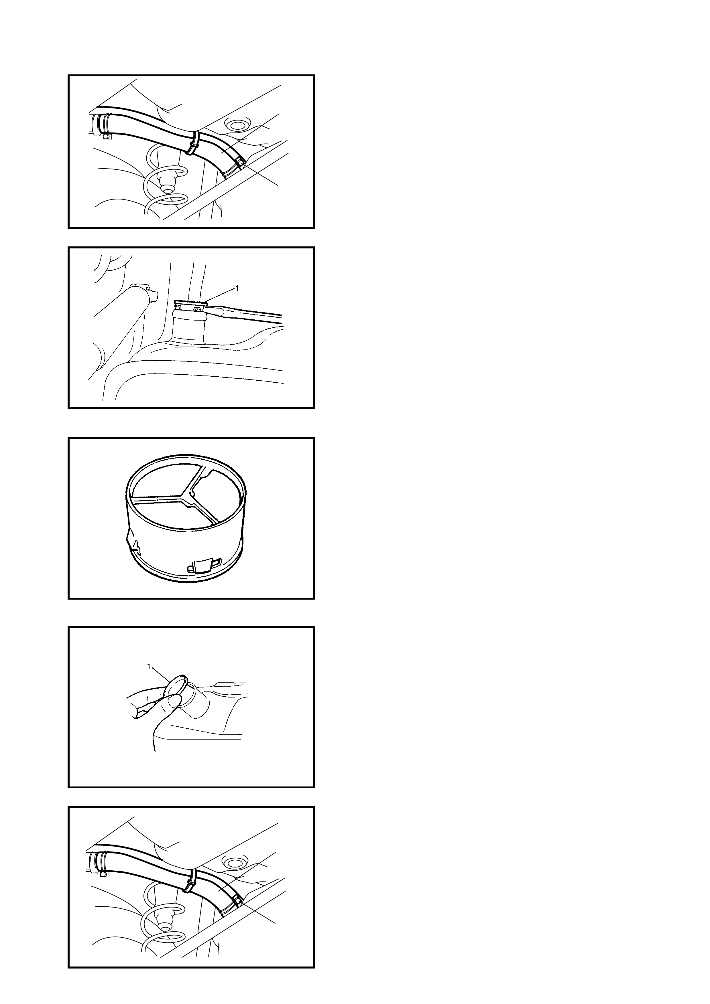
3. Hoist the vehicle and remove the clamp (2) and fuel
filler hose (1) from fuel tank.
4. Remove th e fu el tan k inlet valv e (1 ) us in g a fl at-b lade d
screwdriver as shown.
CAUTION: Take care not to damage the fuel tank inlet
valve (1) with flat- blad ed scr ew drive r.
INSPECTION
Check the fuel tank inlet valve for the following.
•Damage
• Smooth opening and closing
If any damage or malfunction is found, replace the fuel tank
inlet valve.
INSTALLATION
1. Install the fuel tank inlet valve (1) to the fuel tank.
2. Install the fuel filler hose (1) to the fuel tank and secure
it with clamp (2).
For corr ect installat ion, refer t o 2.1, COM PONENTS in
this Section.
3. Lower the vehicle and install the fuel filler cap.
1
2
1
2
2.7 FUEL TANK
REMOVAL
WARNING: Before sta rting the following procedure, be
sure to observe 2.2 PRECAUTIONS in this Section.
1. Relieve fuel pressure in fuel feed line, refer to
Section 6, 1.4 FUEL PRESSURE
RELIEF PROCEDURE.
2. Disconnect the negative cable at battery.
3. Hoist vehicle.
4. Disconnect the fuel filler hose (1) and breather hose (2)
from the filler neck (3).
CAUTION: Never disconnect the fuel filler hose (1)
from the fu el tank inlet. If the fuel tank is more than half
full, fuel will overflow.
5. Due to the absence of a fuel tank drain plug, fuel must
be drained through the fuel tank filler using a hand
operated pump.
CAUTION:
• Do not force the pump hose into the fuel tank, or
the pump hose may damage the fuel tank inlet
valve.
• Never drain or store fuel in an open container due
to possibility of fire or explosion.
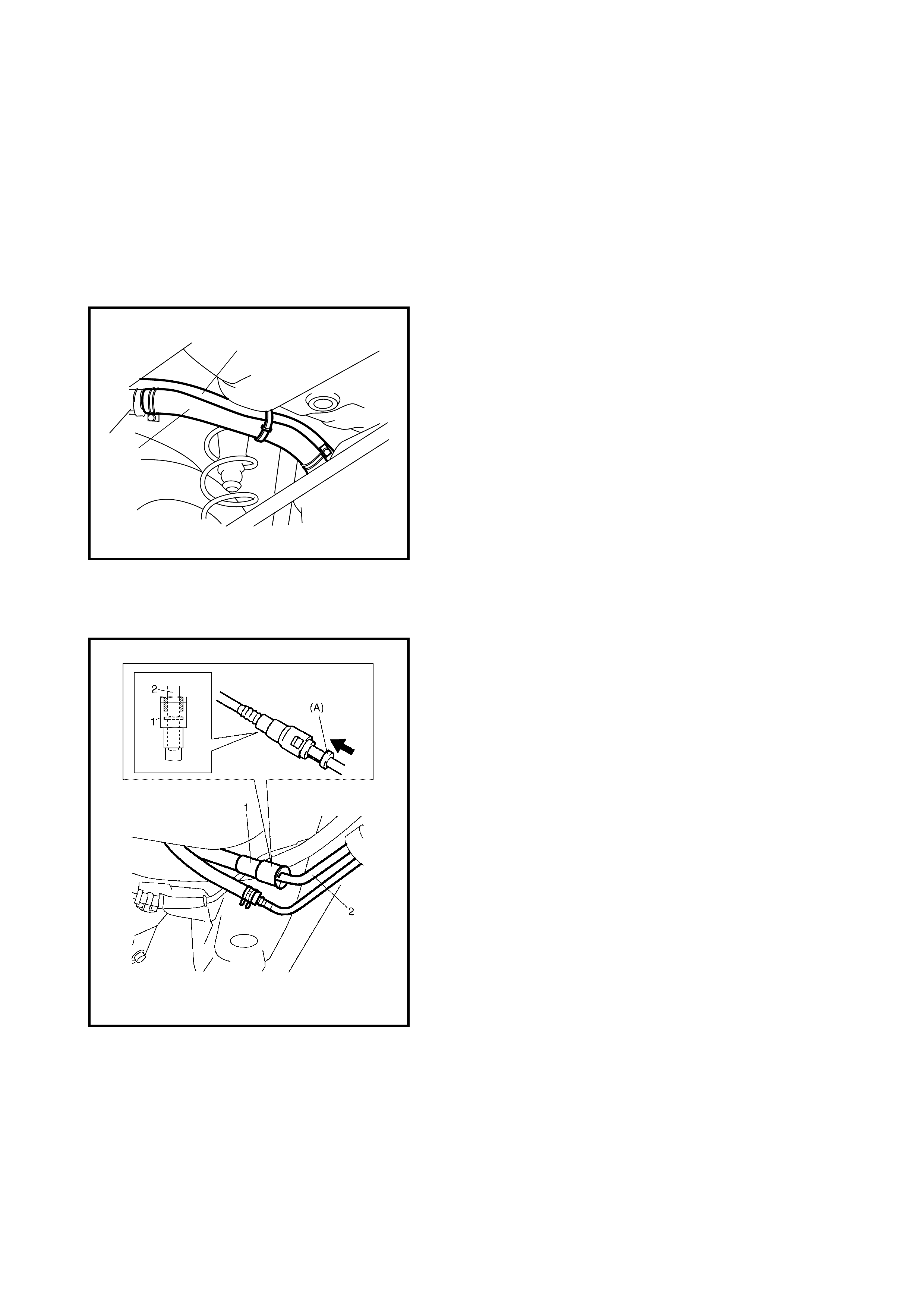
6. Disconnect the fuel pipe joint and fuel hoses from
pipes.
For quick joint, disconnect as follows:-
a. Remove mud, dust and/or foreign material between
pipe and joint by blowing compressed air.
b. Unlock joint (1) lock by inserting special tool 09919-
47020 (A) between pipe (2) and joint (1).
c. Disconne ct joint fro m pipe.
WARNING: A small amount of fuel may be released
after the fuel hose is disconnected. In order to reduce
the chance of persona l injury, cover the ho se and pipe
to be disconnected with a cloth. Be sure to dispose of
cloth in an approved container when work is
completed
2
1
3
4. Support the fuel tank (1) with a jack stand (2) and
remove the fuel tank mounting bolts.
5. Lower the fu el tank sl ightly to allow the wiring harn ess
at the connector (1) to be disconnected, remove the
fuel tank.
INSPECTION
After removing the fuel tank, check hoses and pipes con-
nected to the fue l tank for leaks, loose c onnection s, deteri-
oration or damage. Also check the fuel pump assembly
gaskets for leaks, visually inspect the fuel tank for leaks
and damage.
Replace any damaged or worn parts.
FUEL TANK PURGING PROCEDURE
WARNING: This purging procedure will not remove all
fuel vapour. Do not attempt any repair on tank using
heat or flame as an explosion resulting in personal
injury could occur.
The following procedure is used for purging fuel tank.
1. After removing the fuel tank, remove all hoses, pipes
and the fuel pump assembly from the fuel tank.
2. Drain all remaining fuel from tank.
3. Move tank to flushing area.
4. Fill tank with warm wa ter or tap water, and ag itate vig-
orously and drain. Repeat until inside of tank is clean.
Replace tank if its inside is rusty.
5. Completely flush out remaining water after washing.
CAUTION: Never allow water to remain in fuel tank after
washing, or corrosion of fuel tank could occur.
1
INSTALLATION
1. If parts have been removed from the fuel tank, install
them before installing the fuel tank to the vehicle.
2. Raise the fuel tank (1) with a jack stand and connect
the fuel pump and fuel gauge connector and clamp
wire harness.
3. Install the fuel tank to the vehicle.
4. Connect fuel filler hose (1) and breather hose (2) to
filler neck (3) as shown in the figure and clamp them
securely.
5. Connect the f uel feed hose (1) an d vapour hos e (2) to
each pipe as shown in the figure and clamp them
securely.
CAUTION:
• When connecting joint, clean outside surfaces of
pipe where joint is to be inserted, push joint into
pipe till joint lock clicks and check to ensure that
pipes are connected securely, or fuel leak may
occur.
• Never let the fuel hoses touch the ABS sensor har-
ness (i f eq uippe d ).
6. Connect the negative cable at battery.
With engine OFF, turn the ignition switch to ON
position and check for fuel leaks.
FUEL TANK BOLT (a)
TORQUE SPECIFICATION 23 Nm
FUEL FILLER HOSE CLAMP (a)
TORQUE SPECIFICATION 1.5 Nm
(a)
(a)
1
3
2
2.8 FUEL PUMP ASSEMBLY
WARNING: Refer to 2.2 PRECAUTIONS in this Section.
REMOVAL
1. Remove the fuel tank from the vehicle. Refer to
2.7 FUEL TANK in this Section.
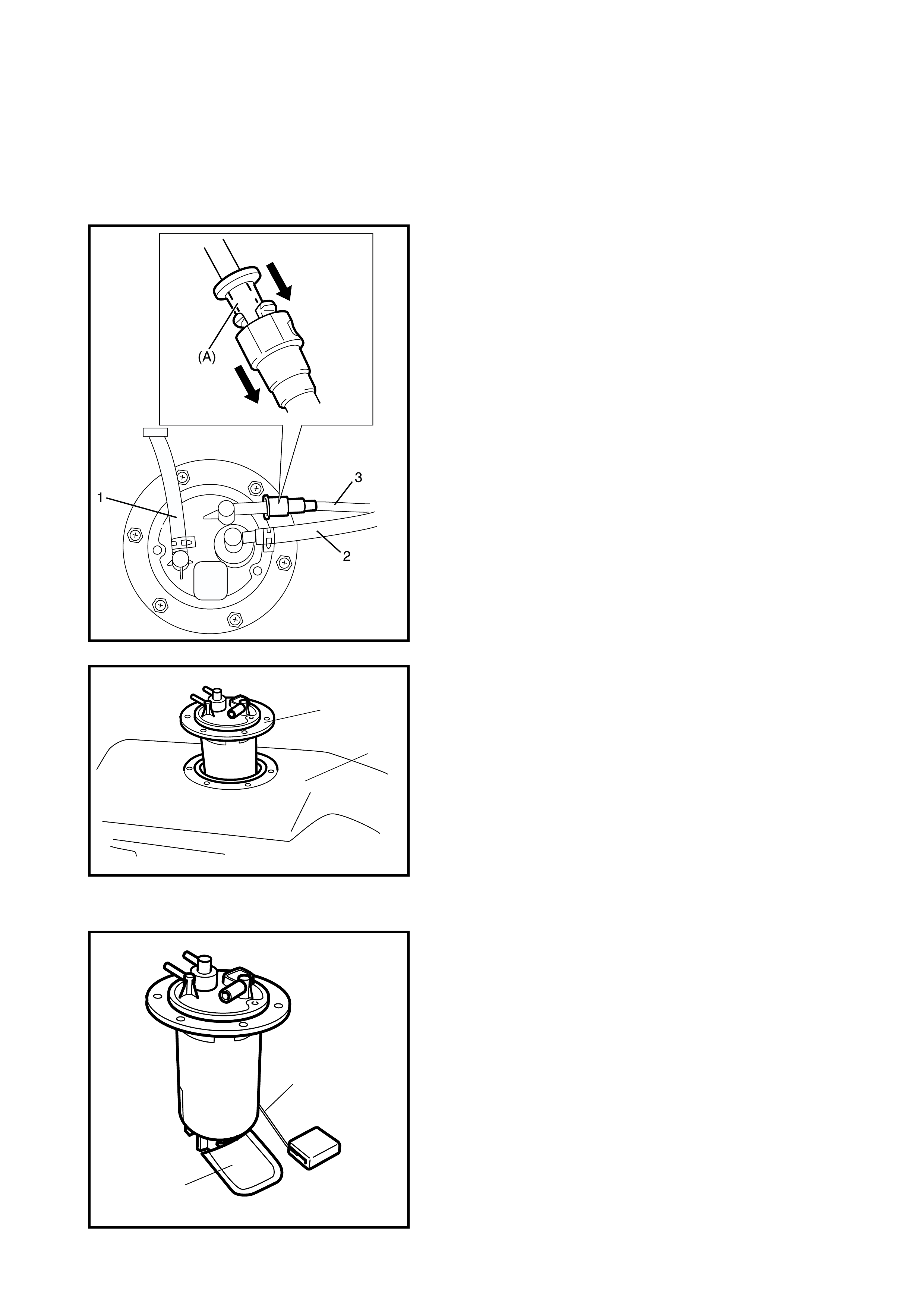
2. Disconne ct the fuel breather hose (1), fuel v apor hose
(2) and pipes from the fuel pump assembly.
When disconnecting the joint on the fuel feed line (3)
from the pipe, unlock joint by inserting special tool
09919-47020 (A) between pipe and joint lock first.
3. Remove fuel pump assembly (1) from fuel tank (2).
INSPECTION
• Check the fuel pump assembly for damage.
• Check the fuel suction filter ( 1) for evidence of di rt and
contamination.
If present, replace or clean and check for presence of
dirt in fuel tank.
• For operation and electrical circuit inspection, refer to
Section 6E1 ENGINE AND EMISSION
CONTROL SYSTEM.
• For inspection of the fuel level gauge (2), refer to
Section 8 BODY ELECTRICAL SYSTEM.
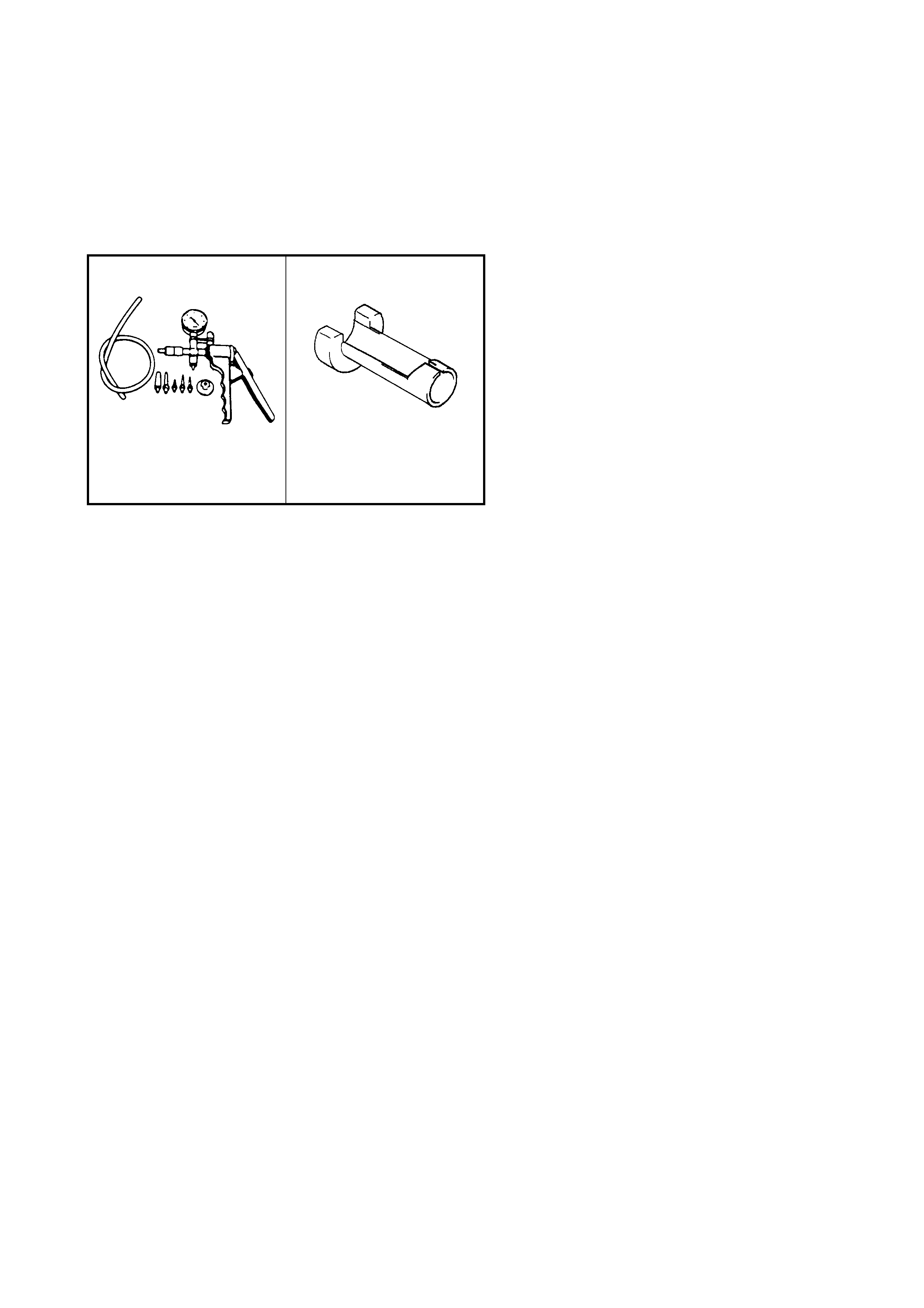
• Check the fuel tank pressure control valve referring to
the following procedu re s.
WARNING:1
Do not suck air through fuel vapour line hose. Fuel
vapour is harmful.
YGM06C01
1
2
1
2
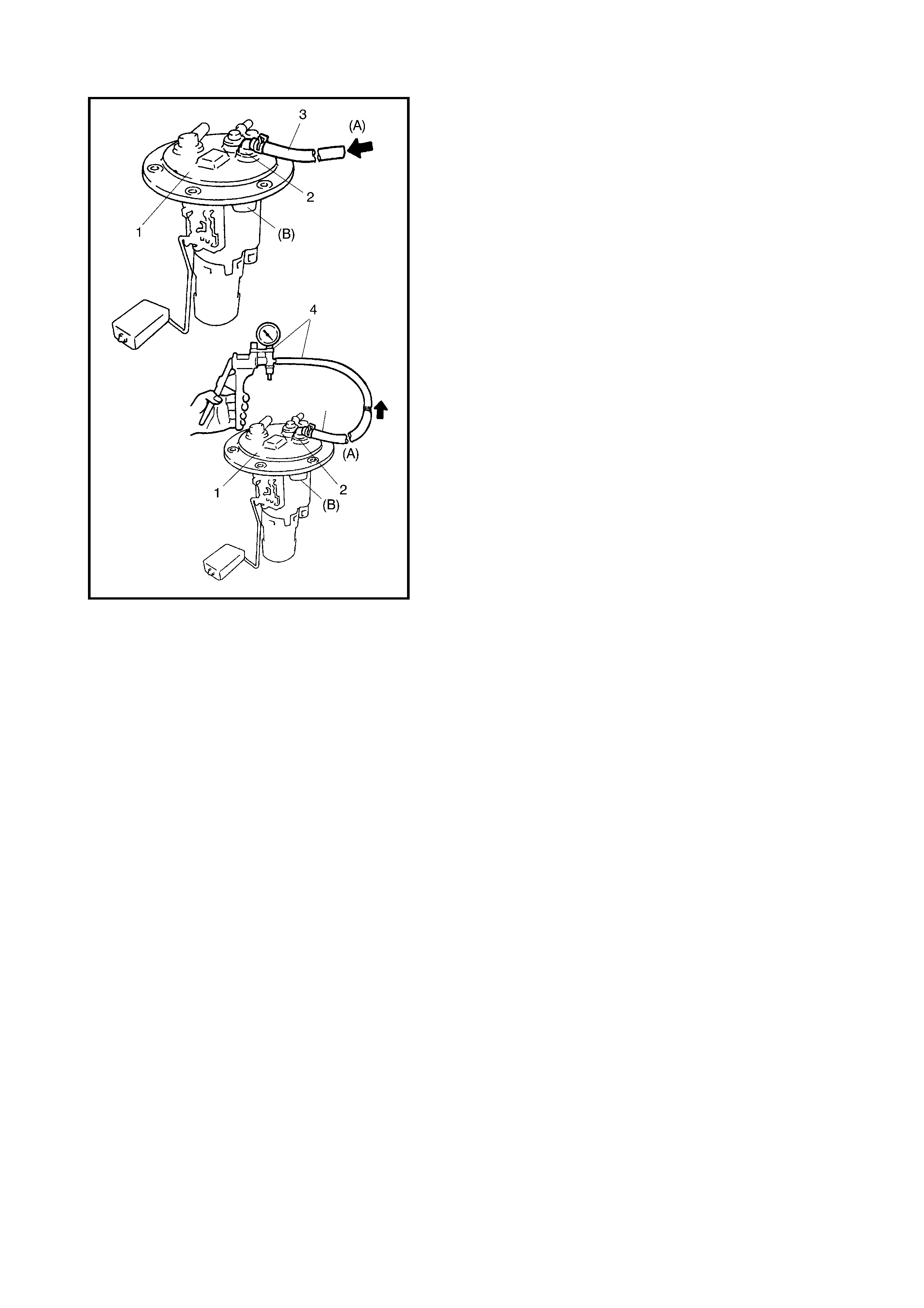
a. Air should pass through the valve (2) smoothly from
(A) fuel vapor line hose (3) to (B) when blown hard.
b. Also, when vacuum pump (4), special tool 09917-
47910, is conne cted t o the fu el va por h ose and th e
vacuum pump is operated, air should pass from (B)
to (A).
If air does not pass through the valve in Step A or vacuum
is maintained in Step B, replace fuel pump assembly (1).
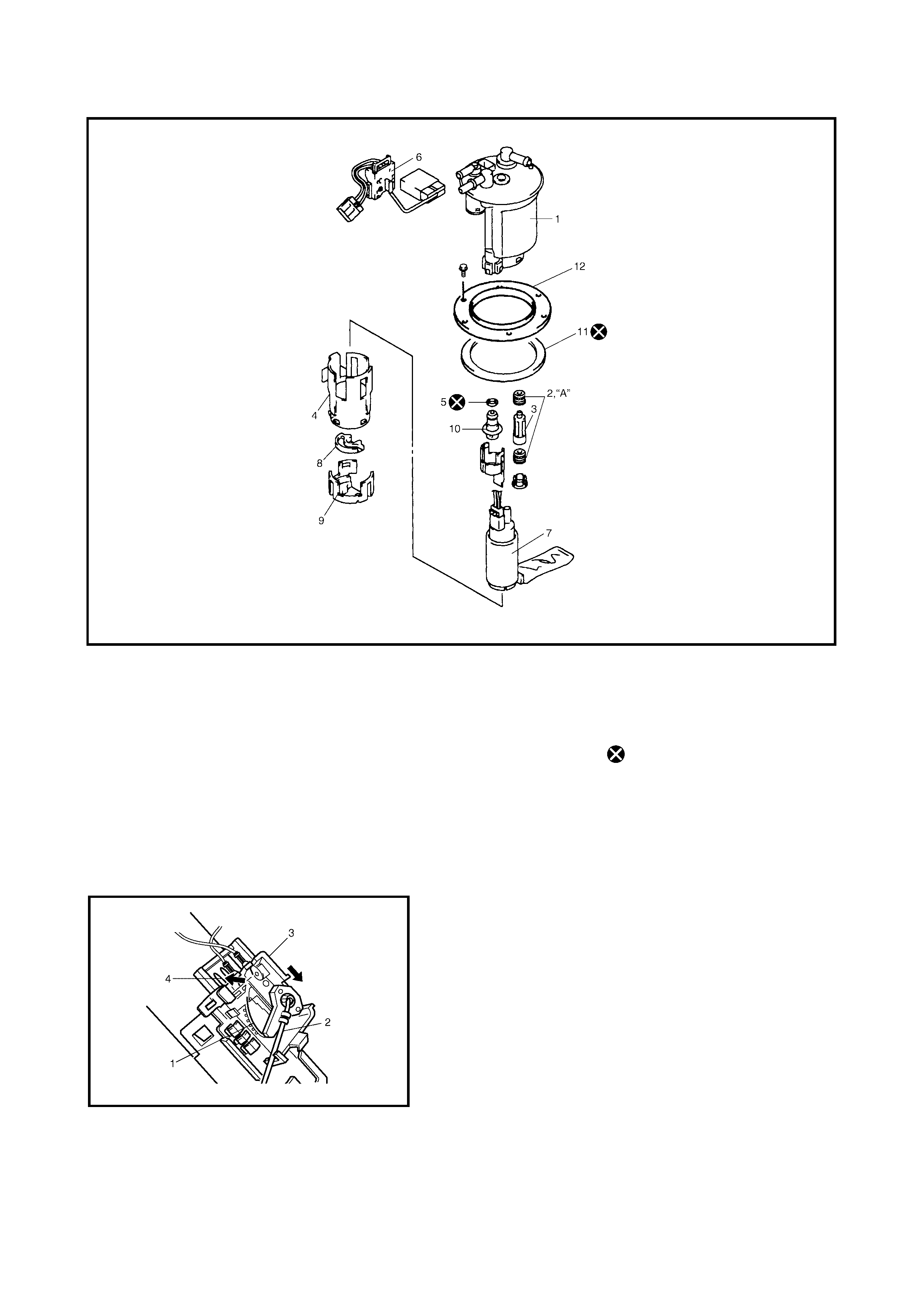
DISASSEMBLY AND REASSEMBLY
Legend
Disassemble and reassemble the fuel pump assembly, not-
ing the following.
CAUTION:
• When removing the fuel level gauge, do not con-
tact resistor plate (1) or deform arm (2). It may
cause the fuel level gauge to fail.
• When removing the grommet from the fuel tube or
bracket sub assembly, be careful not to damage
grommet installed section (sealed section in bore).
Should it be damaged, replace it with a new one, or
fuel leakage may occur.
• When removing the fuel level sensor (3), press snap-fit
part (4) and slide it in the direction indicated in the
figure.
• When installing the fuel level sensor to the housing,
ensure fuel level sensor fits securely.
(A) Apply oil 5. O-ring 10. Fuel pressure regulator
1. Fuel filter assembly
(includi ng ch eck val ve ) 6. Fuel level sensor (Fuel
sender gauge) 11. Gasket
12. Fuel pump plate
2. Grommet 7. Fuel pump Do not reuse.
3. Tube 8. Cushion
4. Housing 9. Bracket
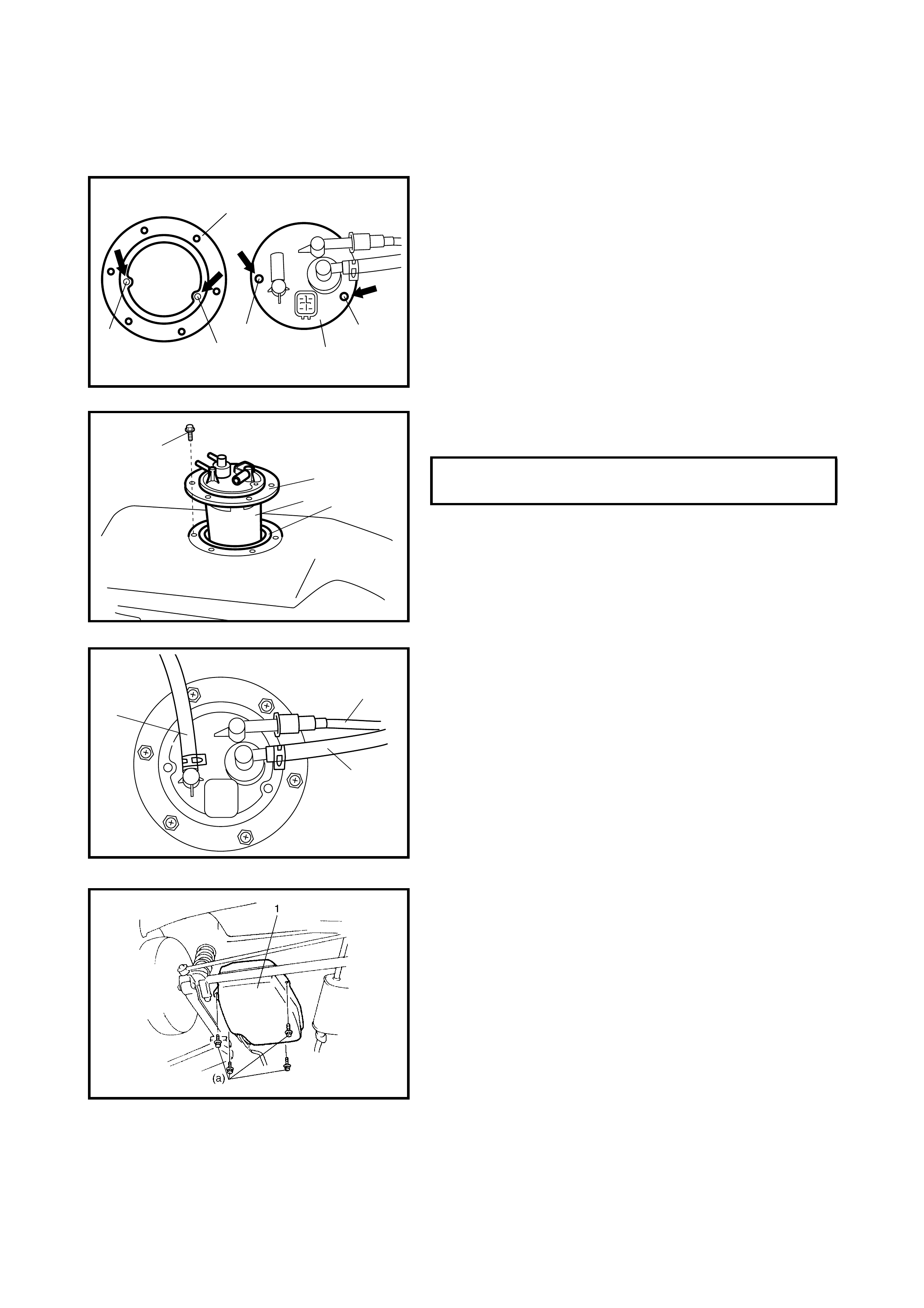
INSTALLATION
1. Clean the mating surfaces of the fuel pump assembly
(1) and fuel tank.
2. Place the plate (2) on the fuel pump assembly (1) by
matching the protrusions on the fuel pump assembly
(3) with the plate holes (4) as shown.
3. Install a new gasket (2) and fuel pump assembly (1)
with plate (3) to the fuel tank.
4. Connect th e fu el br eat her hose (1) , fu el va por h os e ( 2)
and fuel feed line (3) (pipe joint) to the fuel pump
assembly.
CAUTION: When connecting joint, clean outside sur-
face of pipe where joint is to be inserted, push joint
into pipe until joint lock clicks and check to ensure that
pipes are connected securely, or fuel leakage may
occur.
5. Install fuel tank (1) to v ehicle, r efer to 2.7, FUEL TANK
in this Sectio n.
3
2
4
43
1
FUEL PUMP ASSEMBLY BOLTS (a)
TORQUE SPECIFICATION 10 Nm
3
12
(a)
1
2
3