
SECTION 6F1 - ELECTRONIC IGNITION SYSTEM
1. GENERAL DESCRIPTION
1.1 SYSTEM COMPONENTS
1.2 SYSTEM WIRING DIAGRAM
2. DIAGNOSIS
2.1 DIAGNOSIS TABLE
2.2 IGNITION SYSTEM DIAGNOSTIC
FLOW TABLE
3. ON-VEHICLE SERVICE
3.1 IGNITION SPARK TEST
3.2 HIGH-TENSION LEADS
3.3 SPARK PLUGS
3.4 IGNITION COIL ASSEMBLY
(INCLUDING IGNITOR)
Inspection
3.5 CRANKSHAFT POSITION SENSOR
(CKP SENSOR)
3.6 IGNITION TIMING
Inspection
WARNING:
For vehicles equipped with Supplementary Restraint (Airbag) System:
• Service on and around the airbag system components or wiring must be performed only by an
authorised HOLDEN retailer. Refer to AIRBAG SYSTEM COMPONENTS and WIRING LOCATION
VIEW under GENERAL DESCRIPTION in Section 10B AIRBAG SYSTEM in order to confirm
whether you are performing service on or near the airbag system components or wiring. Please
observe all WARNINGS and SERVICE PRECAUTIONS under ON-VEHICLE SERVICE in Section
10B AIRBAG SYST EM before performing service on or around the airbag sys tem components or
wiring. Failure to follow WARNINGS could result in unintentional activation of the system or
could render the system inoperative. Either of these two conditions may result in severe injury.
•
Technical service work must be started at least 90 seconds after the ignition switch is turned to
the “LOCK” position and the negative cable is disconnected from the battery. Otherwise, the sys-
tem may be activated by reserve energy in the Sensing and Diagnostic Module (SDM)
.
IMPORTANT:
Prior to connecting Tech 2 to the vehicle, refer to Section 0C TECH 2.

1. GENERAL DESCRIPTION
The i gnition syste m is an electroni c (no distribu tor) ignition system. Its has an electronic i gnition control s ys-
tem and consists of the parts described below.
•ECM
It detects the engine and vehicle conditions via signals from the various sensors, determines the most
suitable ignition timing and the right moment for electricity to flow to the primary coil and sends a signal to
the ignitor (power unit) in the ignition coil assembly.
• Ignition coil assembly (including an ignitor)
The ignition coil assembly has a built-in ignitor which turns ON and OFF the current flow to the primary coil
according to the signal from the ECM. When the current flow to the primary coil is turned OFF, a high volt-
age is induced in the secondary coil.
• High tension leads and spark plugs.
• CMP sensor (Camshaft position sensor) and CKP sensor (Crankshaft position sensor)
Using signals from these sensors, the ECM identifies the specific cylinder whose piston is in the compres-
sion stroke, detects the crank angle and adjusts the initial ignition timing automatically.
• TP sensor, ECT sensor, MAP sensor and other sensors/switches
Refer to Section 6E1 ENGINE AND EMISSION CONTROL SYSTEM for details.
Although this ignition system does not have a distributor, it has two ignition coil assemblies (one is for the
No.1 and No.4 spark plugs and the other is for the No.2 and No.3 spark plugs). When an ignition signal is sent
from the ECM to the ignitor in the ignition coil assembly for No.1 and No.4 spark plugs, a high voltage is
induced in the secondary coil and that passes through the high-tension leads and causes No.1 and No.4
spark plugs to spark simultaneously. Likewise, when an ignition signal is sent to the ignitor in the other ignition
coil assembly, No.2 and No.3 spark plugs spark simultaneou sly.
1.1 SYSTEM COMPONENTS
Legend
1. ECM 5. CKP sensor 11. High-tension leads
2. Ignition coil assembly for
No.1 and No.4 spark plugs 6. MAP sensor 12. Diagnosis connector No.1
7. ECT sensor 13. Knock sensor
3. Ignition coil assembly for
No.2 and No.3 spark plugs 8. IAT senso r 14. D ata link co nne ctor
9. TP sensor
4. CMP sensor 10. VS S
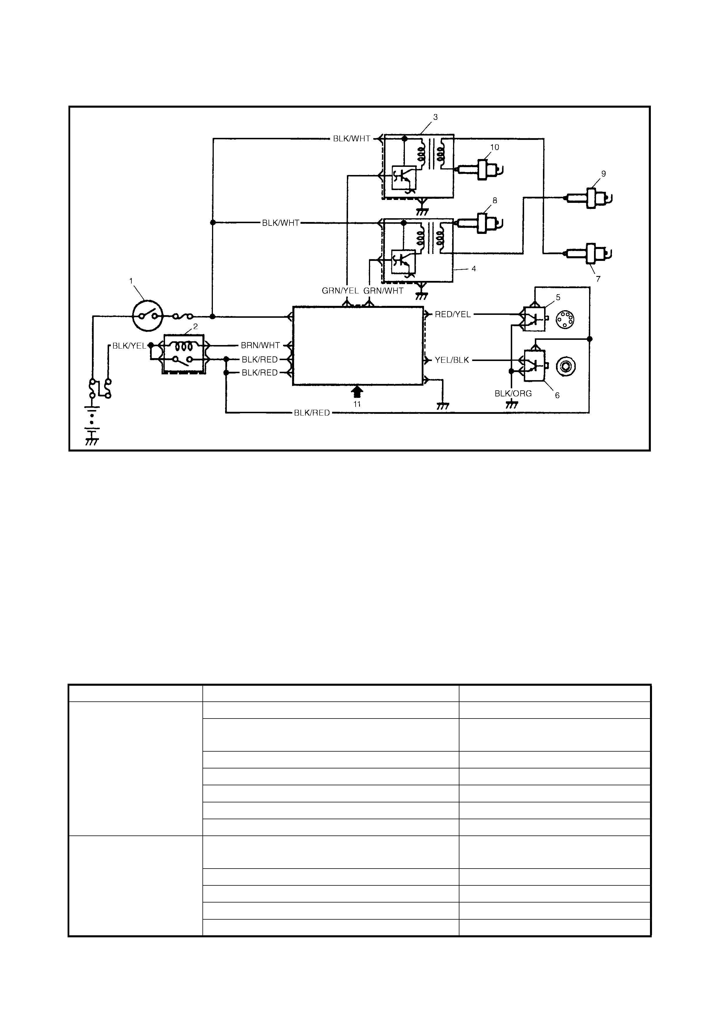
1.2 SYSTEM WIRING DIAGRAM
Legend
2. DIAGNOSIS
2.1 DIAGNOSIS TABLE
1. Ignition switch 5. CMP sensor 11. Sensed information (MAP
sensor , ECT sensor, IAT
sensor, TP sensor, Knock
sensor , VSS, Electric load
signal, Engine start signal,
Test switch terminal)
2. Main relay 6. CKP sensor
3. Ignition coil assembly for 7. No.1 spark plug
No.1 and No.4 spark plugs 8. No.2 spark plug
4. Ignition coil assembly for 9. No.3 spark plug
No.2 and No.3 spark plugs 10. No.4 spark plug
Condition Possible Cause Correction
Engine cranks, but
will not start or is
hard to start (No
spark)
Blown fuse for ignition coil Replace.
Loose connection or disconnection of lead
wire or high-tension lead(s) Connect securely.
Faulty high-tension lead(s) Replace.
Faulty spark plug(s) Adjust, clean or replace.
Faulty ignition coil Replace ignition coil assembly.
Faulty CKP sensor or CKP sensor plate Clean, tighten or replace.
Faulty ECM Replace.
Poor fuel economy or
engine performance Incor re ct igniti on tim ing Check rela ted se nsor s and CKP
sensor plate.
Faulty spark plug(s) or high-tension lead(s) Adjust, clean or replace.
Faulty ignition coil assembly Replace.
Faulty CKP sensor or CKP sensor plate Clean, tighten or replace.
Faulty ECM Replace.

2.2 IGNITION SYSTEM DIAGN OSTIC FLOW TABLE
Step Action Yes No
1 Were the steps in Section 6 2.4 ENGINE DIAGNOSTIC
FLOW TABLE performed? Go to Step 2. Go to Section 6, 2.4
ENGINE DIAGNOS-
TIC FLOW TABLE.
2 Ignition Spark Test
Check all spark plugs for condition and type, refer to 3.3
SPARK PLUGS in this Section.
If OK, perform ignition spark test, refer to 3.1 IGNITION
SPARK TEST in this Section.
Is spark emitted from all spark plugs?
Go to Step 11. Go to Step 3.
3 Diagnostic Trouble Code (DTC) Check Is DTC stored in
ECM? Go to the applica-
ble DTC DIAGNOS-
TIC FLOW TABLE
in Section 6.
Go to Step 4.
4 Electrical Connection Check
Check ignition coil assemblies and high-tension leads
for electrical connection.
Are they connected securely?
Go to Step 5. Connect securely.
5 High-ten sion Lea ds Check
Check high-tension leads for resistance refer to 3.2
High-Tension Leads in this Section.
Is check result satisfactory?
Go to Step 6. Replace high-tension
lead(s).
6 Ignition Coil Assembly Power Supply and Ground Cir-
cuit Check
Check ignition coil assembly power supply and ground
circuits for open and short.
Are circuits in good condition?
Go to Step 7. Repair or replace.
7 Ignition Coil Assembly Check
Check ignition coil for resistance refer, to 3.4 IGNITION
COIL ASSE MB LY in th is Sec tion.
Is check result satisfactory?
Go to Step 8. Replace ignition coil
assembly.
8 Crankshaft Position (CKP) Sensor Check
Check crankshaft position sensor, refer to Step 3 and 4,
Section 6, 2.20 DTC P0335 (No.23) CRANKSHAFT
POSITION SENSOR (CKP) CIRCUIT MALFUNCTION,
flow table.
Is check result satisfactory?
Go to Step 9. Tighten CKP sensor
bolt, replace CKP sen-
sor or CKP sensor
plate.
9 Ignition Trigger Signal Circuit Chec k
Check ignition trigger signal wire for open, short and
poor connection.
Is circuit in good conditi on?
Go to Step 10. Repair or replace.
10 A Known-good Ignition Coil Assembly Substitution
Substitute a known-good ignition coil assembly and
then repeat Step 2.
Is check result of Step 2 satisfactory?
Go to Step 11. Substitute a known-
good ECM and then
repeat Step 2.
11 Ignition Timing Check
Check initial ignition timing and ignition timing advance,
refer to 3.7 IGNITION TIMING in this Section.
Is check result satisfactory?
System is in good
condition. Check CKP sensor,
CKP sensor plate and
input signals related to
this system.
3. ON-VEHICLE SERVICE
3.1 IGNITION SPARK TEST
1. Disconnect all injector connectors (1) from the injec-
tors, refer to Section 6E1, 2.2 FUEL DELIVERY
SYSTEM - FUEL INJECTOR.
WARNING: If the injector connectors are not discon-
nected during this test, combustible gas may be emit-
ted from the spark plug holes and may ignite in the
engine bay.
2. Remove the spark plug and check its condition and
type, refer to 3.3 SPARK PLUGS in this Section.
3. If OK, conn ec t the i gni tio n coi l con nec tor to the i gnitio n
coil assembly and connect the spark plug to the
ignition coil assemb ly or high -tensio n lead . Groun d the
spark plug.
4. Crank the engine and observe if the spark plug emits a
spark.
5. If there is no spark, inspect the related parts, refer to
2. DIAGNOSIS in this Section.
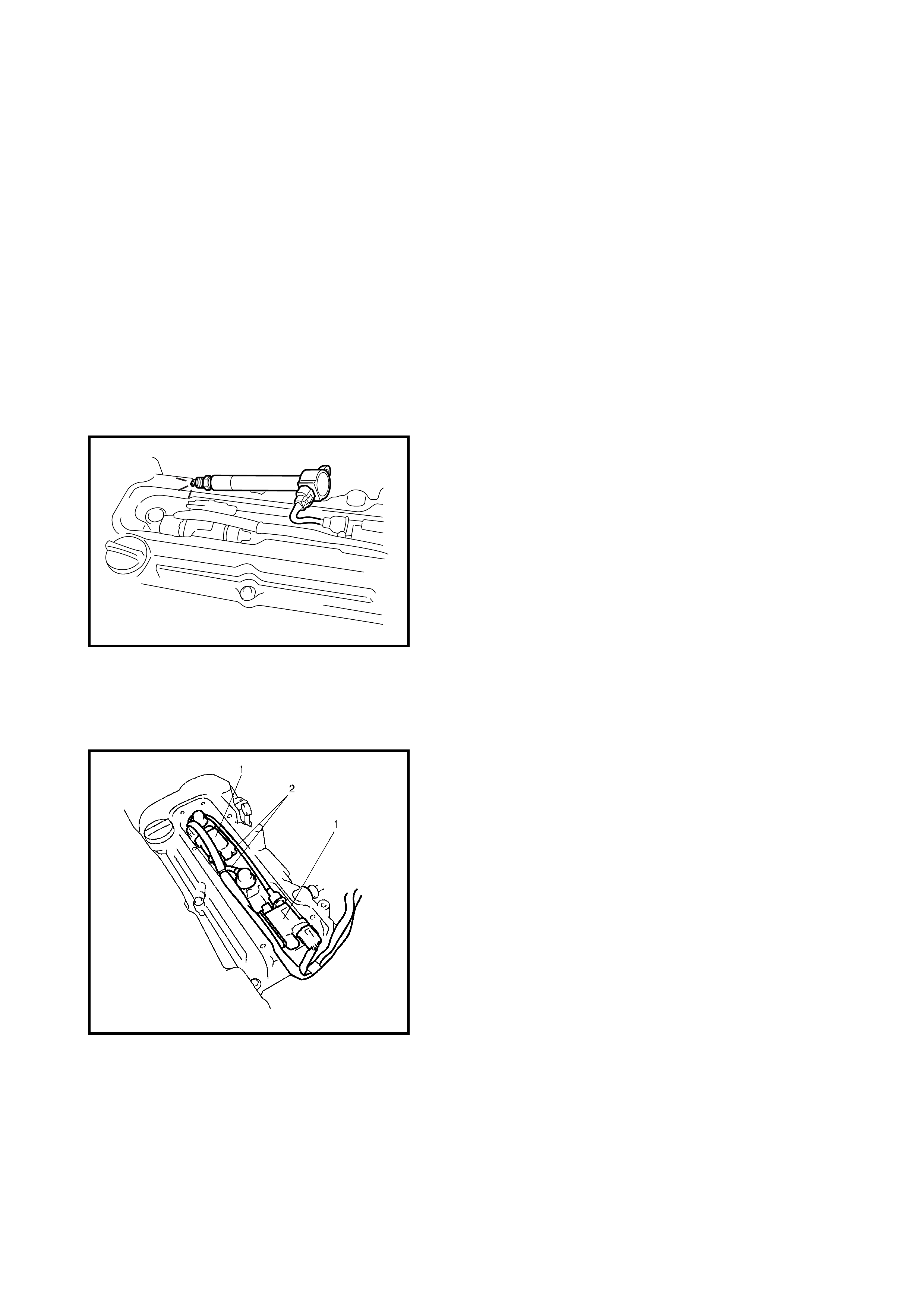
3.2 HIGH-TENSION LEADS
1. Remove the air intake pipe and the cylinder head
upper cover.
2. Disconne ct the high-te nsion leads (2) from th e ignition
coil assemblies (1) carefully by pulling on caps.
3. Remove the high-tension leads from the spark plugs
carefully by pulling on caps.
CAUTION:
• Removal of the high-tension leads together with
their clamps is recommended, to avoid damaging
the inner wire (resistive conductor).
• Similarly, pull out each connection by gripping the
cap portion of the lead.
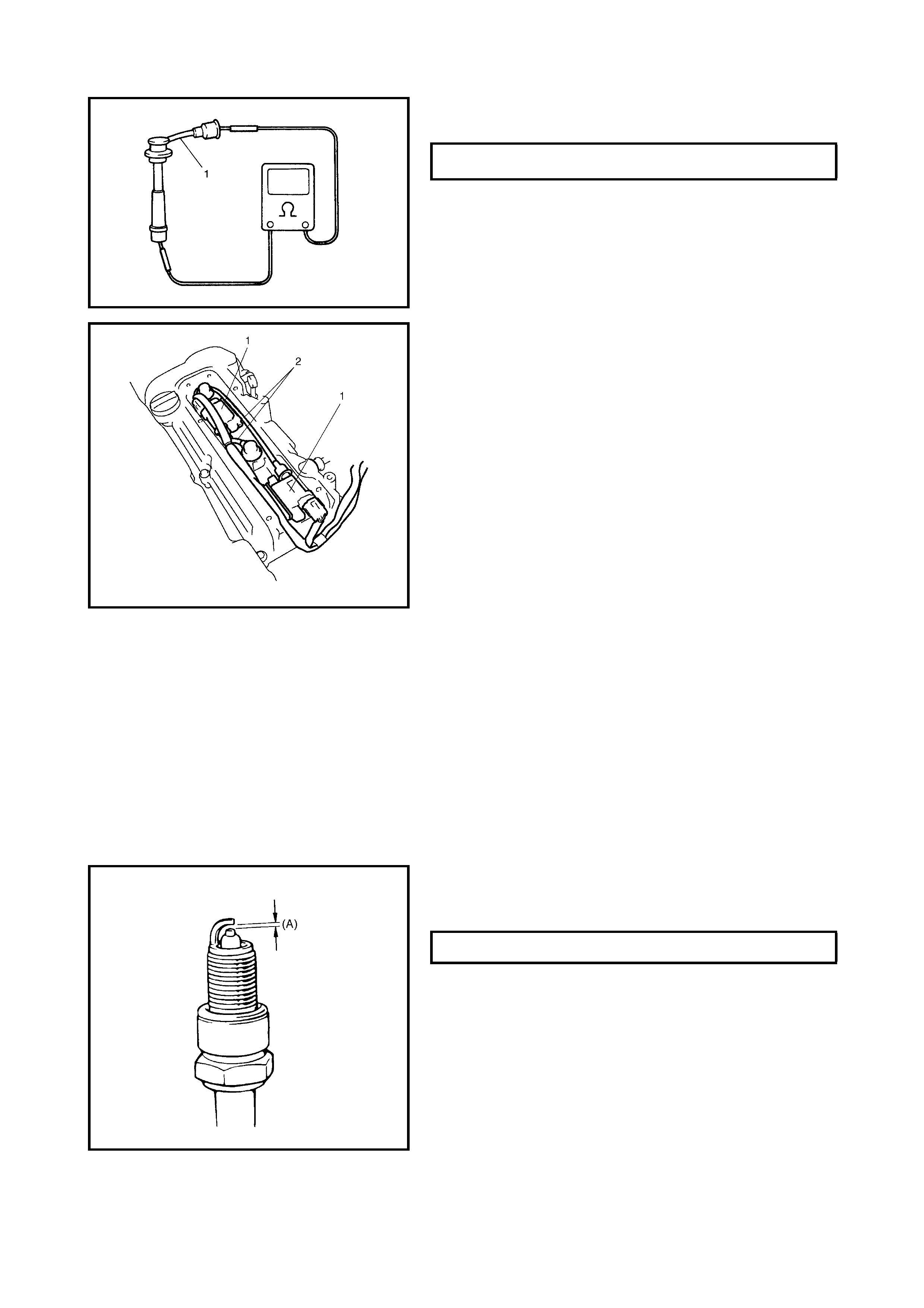
4. Measure the resistance of the high-tension lead(s) (1)
using an ohmmeter.
5. If the resistance exceeds specification, replace the
high-tension lead(s).
6. Install the high-tension leads (2) to the spark plugs and
ignition coil assemblies (1) holding the cap portion of
the lead.
CAUTION:
• Never use metal conductor high-tension leads as
replacement parts.
•
Insert each cap portion fully when installing
high-tension leads.
3.3 SPARK PLUGS
1. Remove the air cleaner inlet hose and the cylinder
head upper cover.
2. Pull out the high-tension leads by gripping their caps
then remove the ignition coil assemblies, refer to
3.4 IGNITION COIL ASSEMBLY in this Section.
3. Remove the spark plugs.
4. Inspect them for:
•Electrode wear
•Carbon deposits
•Insulato r damage
5. If any defects are found, adjust air gap, clean with
spark plug cleaner or replace them with specified new
plugs.
Spark plug type
NGK: BKR5E-11, IFR5E11/IFR6E11
DENSO: K16PR-U11
During December 2002 vehicle production, spark plugs were
changed to NGK: IFR5J11/IFR6J11.
.
CAUTION:
• When servicing the iridium/platinum spark plugs
(slender centre electrode type plugs), do not touch
the centre electr ode to avoid damage.
• Do not clean or adjust the gap on iridium/platinum
spark plugs .
HIGH TENSION LEAD RESISTANCE 4 - 10 k
Ω
/m
SPARK PLUG AIR GAP (A) 1.0 1.1 mm
6. Install the spark plugs and torque them to specification.
7. Install the ignition coil assemblies, refer to
3.4 IGNITION COIL ASSEMBLY in this Section.
8. Install the high-tension leads securely by gripping the
cap portion of the leads.
9. Install the cylinder head upper cover and air intake
pipe.
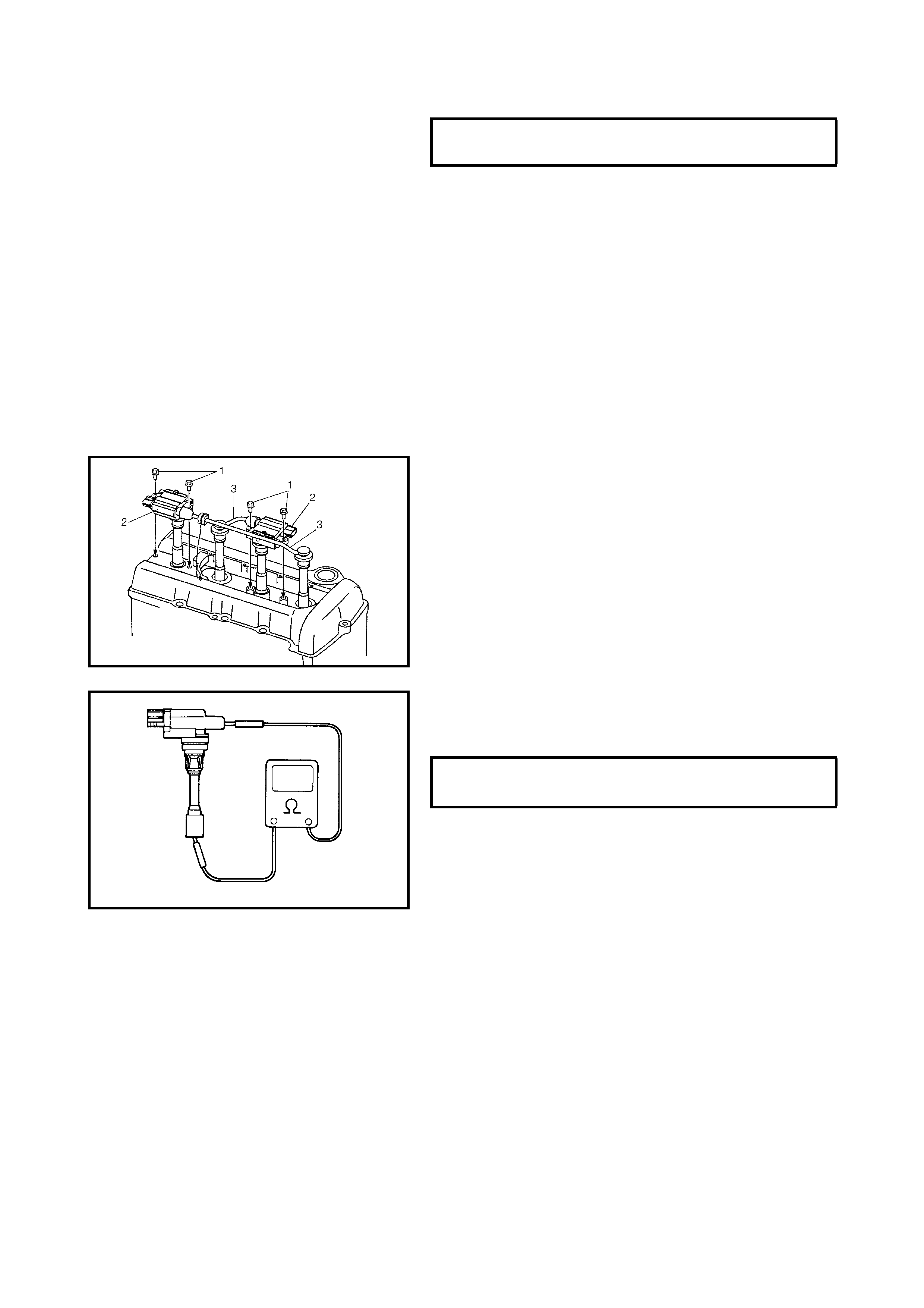
3.4 IGNITION COIL ASSEMBLY
(INCLUDING IGNITOR)
INSPECTION
1. Disconnect negative cable at battery.
2. Remove air intake pipe and cylinder head upper cover.
3. Disconnect ignition coil coupler.
4. Disconnect high-tension lead (3) from ignition coil
assembly (2).
5. Remove ignition coi l bolts (1) an d then pull out ignitio n
coil assembly.
6. Measure secondary coil for resistance.
If resistance is out of specification, replace ignition coil
assembly.
7. Install ignition coil assembly.
8. Tighten ignition coil bolts, and then connect ignition coil
coupler.
9. Install hig h-tension lead to ign ition coil assembly w hile
gripping its cap.
10. Install the cylinder head upper cover and air cleaner
inlet hose.
3.5 CRANKSHAFT POSITION SENSOR
(CKP SENSOR)
Refer to Section 6E1, 2.3 ELECTRONIC CONTROL
SYSTEM - CRANKSHAFT POSITION SENSOR for
removal, inspection and installation.
SPARK PLUG
TORQUE SPECIFICATION 25 Nm
SECONDARY COIL RESISTANCE 7.6 - 10.2
k
Ω
@ 20
°
C
3.6 IGNITION TIMING
NOTE:
• The ignition timing is not adjustable. If the ignition tim-
ing is out of specification, check the system related
parts.
• Before starting the engine, place the transmission gear
shift lever in NEUTRAL (shift selector lever to (P) for A/
T model), and engage parking brak e.
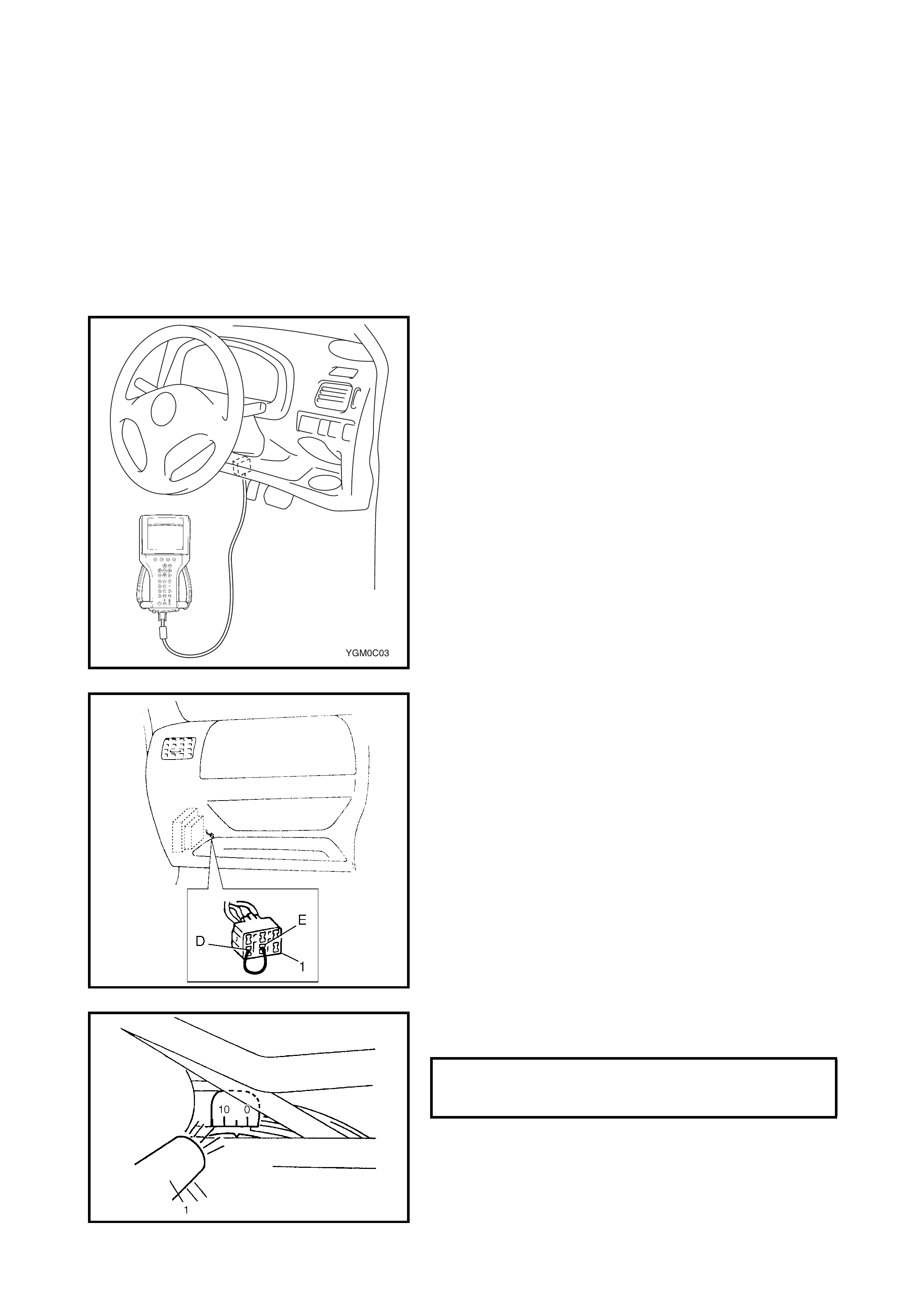
INSPECTION
1. When using TECH 2, connect TECH 2 to DLC with
ignition swi tch OF F.
2. Start the engine and run it until it reaches normal
operating temperature.
3. Ensure that all of electrical loads, except ignition, are
switched off.
4. Ensure that the idle speed is within specification.
Refer to Section 6E1, 2. ON-VEHICLE SERVICE -
IDLE SPEED / IDLE AIR CONTROL DUTY
INSPECTION.
5. Set ignition timing to initial one as follows.
Select “MIS C” mode on TECH 2 an d fix ignition ti ming
to initial one.
If TECH 2 is not available, connect D and E terminals
of diagnosis connector No. 1 (1) using jump wire so
that the ignition timing is fixed.
6. Using a timing light (1 ), check t hat the ignition tim ing is
within sp ec ifica t io n.
Ignition firing order
:1 - 3 - 4 - 2
INITIAL IGNITION TIMING (TEST
SWITCH TERMINAL GROUNDED OR
FIXED WITH TECH 2 5 ± 3° BTDC
AT IDLE

7. If ignition timing is out of specification, check the fol-
lowing:
•CKP sensor
•CKP sensor plate
•TP sensor
•Test switch signal circuit
•VSS
•Timing cha in cover installa t io n
8. After checking Initial Ignition Timing, release the
ignition timing using TECH 2 or disconnect jump wire
from diagnosis connector No.1.
9. With the engine at idle speed (the test switch terminal
ungrounded, throttle opening in closed position and car
stationary), check that the ignition timing is about 7°–
17° BTDC. (Constant variation within a few degrees
from 7°–17° indicates no abnormality but proves
operation of electronic timing control system.) Also,
check that increasing the engine speed advances the
ignition tim ing .
If the above check results are not satisfactory, check
CKP sensor, test switch terminal circuit and ECM.