
SECTION 6G - CRANKING SYSTEM
1. GENERAL DESCRIPTION
1.1 CRANKING CIRCUIT
2. DIAGNOSIS
2.1 DIAGNOSIS TABLE
2.2 PERFORMANCE TEST
Pul l-i n Te st
Ho ld -in Test
Plunger and Pinio n Ret urn Test
No -load Pe rf orm ance Test
3. ON-VEHICLE SERVICE
3.1 STARTING MOTOR
Removal
Installation
Disass embl y and Reassem bly
4. SPECIFICATION
5. REQUIRED SERVICE MATERIAL
WARNING:
For vehicles equipped with Supplement Restraint (Airbag) System:
• Service on and around the airbag system components or wiring must be performed only by
an authorised HOLDEN retailer. Refer to AIRBAG SYSTEM COMPONENTS and WIRING
LOCATION VIEW under DIAGNOSIS in Section 10B AIRBAG SYSTEM in order to confirm
whether you are performing service on or near the airbag system components or wiring.
Please observe all WARNINGS and SERVICE PRECAUTIONS under PRECAUTIONS in Sec-
tion 10B AIRBAG SYSTEM section before performing service on or around the airbag system
compo nen ts or wir i ng. F a i lur e to f o l lo w WARNI NGS c oul d re sul t i n un inte nt io nal a cti vat i on of
the system or could render the system inoperative. Either of these two conditions may result
in severe injury.
• Technical service work must be st arted at least 90 seconds after the ignition switch is t urned
to the “LOCK” position and the negative cable is disconnected from the battery. Otherwise,
the system may be activated by reserve energy in the Sensing and Diagnostic Module (SDM).
1. GENERAL DESCRIPTION
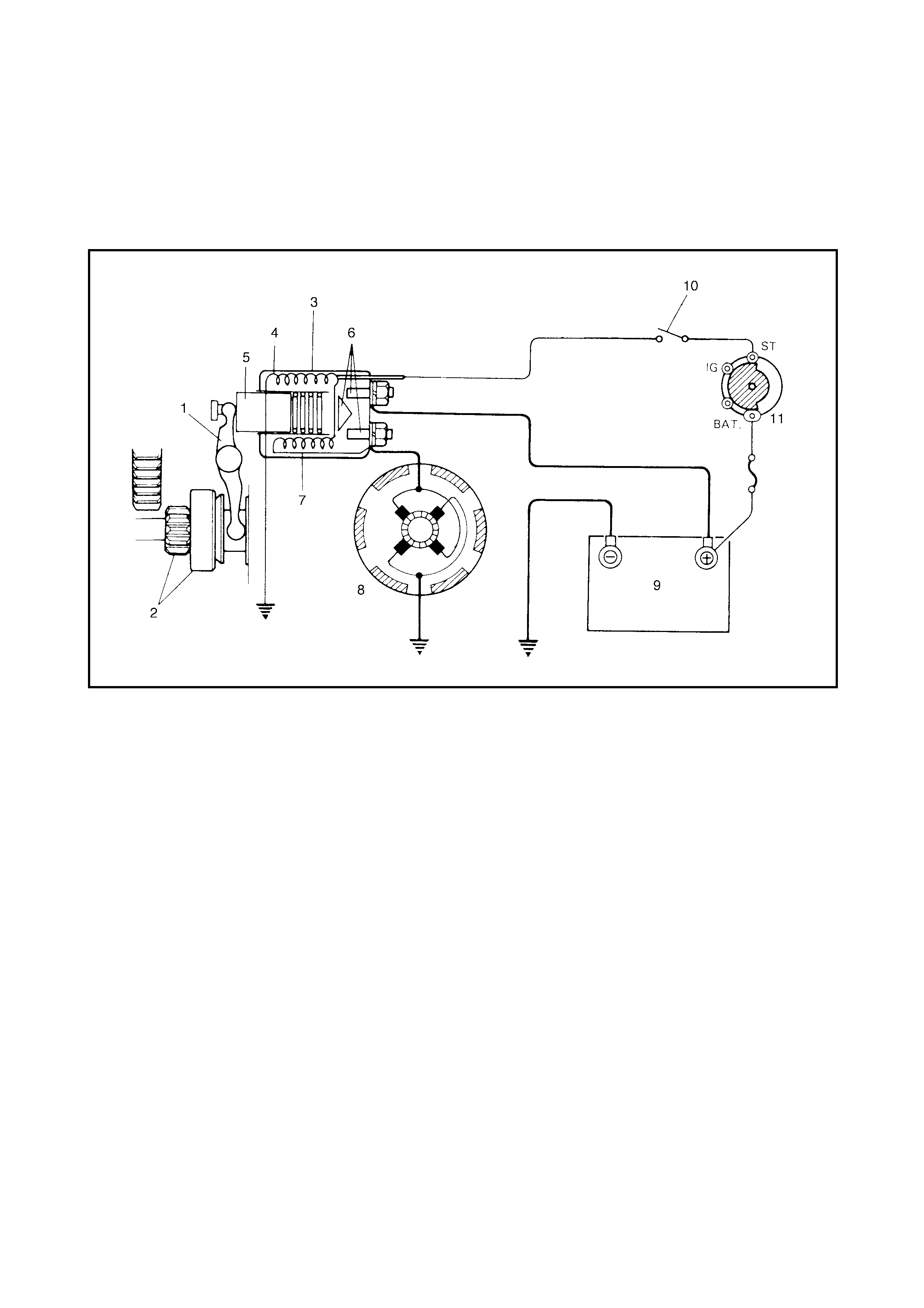
1.1 CRANKING CIRCUIT
Legend
2. DIAGNOSIS
2.1 DIAGNOSIS TABLE
Sympto ms indicatin g possi ble starting system problems:-
• Starting motor does not run (or runs slowly)
• Starting mo tor runs but fails to crank engine
• Abnor mal noise
Correct dia gnosis must b e made to deter mine exactly the cause of each p roblem:- in the batter y, wiring har-
ness, (including starting motor switch), starting motor or engine.
Do not remov e the starting motor just because the starting motor does not run. Check the following items and
narrow down the range of possible causes .
1. Condition or problem.
2. Tightness of battery terminals (including ground cable connection on engine side) and starting motor
terminals.
3. Condition of battery.
4. Mount ing of star t ing motor.
1. Pinion drive lever 6. Magn eti c switch contac ts 10. A/T: Transm ission range
switch (shift lever switch)
2. Pinion & Over-run ning clutch 7. Pull-in coil
3. Magnetic switch 8. Starting motor 11. Ignition & Star te r switch
4. Hold-in coil 9. Battery
5. Plunger

Con diti on Po ssi ble Cause Corre ct ion
Motor no t ru nning
(N o operating so und
from m agnetic sw itch)
Shift lev er switch is not in P or N, or not adjusted
(A/T) Shift in P or N, or adjust switch.
Batter y run down Recharge battery.
Batter y voltage too low due t o batter y
deterioration Replace battery.
Poo r contact in batter y terminal connect ion Retighten or replace.
Loose grounding cable connection Retighten.
Fuse loose or blown Tighten or replace.
Poor contacting action of ignition s witch and
magnetic switch Replace.
Lead wire connector loose Retighten.
Open-circuit between ignition swi tch and mag-
netic switch Repair.
Open-circuit in pull-in coil Replace magnetic switch.
Brushes are seating poorly or worn down Repair or replace.
Poo r sliding of plunger and/or pinion Repair.
Motor no t ru nning
(Op erating so und f rom
ma gnetic switch
heard)
Batter y run down Recharge battery.
Batter y voltage too low due t o batter y deter iora-
tion Replac e battery.
Loose batter y c able connections Retighten.
Burn t main contact point, or p oor contact ing
action of magnetic switc h Replace magnetic switch.
Brushes are seating poorly or worn down Repair or replace.
Weakened brush spring Replace.
Burn t commutator Replace arm at ure.
Layer short-circuit of arm atu re Replace.
Crankshaft rotation obstructed Repair.
Starting motor running
but too slow ( sm al l
torque) (If battery and
wir ing are satisfac-
tory, inspect starting
motor)
Insufficient contact of magnetic sw itch main con-
tacts Replace magnetic switch.
Layer short-circuit of arm atu re Replace.
Disconnected, burn t or worn commutator Repair commutator or replace
armature.
Worn brushes Replace brush.
Weakened brush springs Replace spring.
Burn t or abnor m ally worn end bush Repla ce bu sh .
Starting motor run-
ning, but no t cra nki ng
engine
Worn pinion tip Replace over-running clutch.
Poo r sliding of over-r unning clutch Repair.
Over-running clutch slipping Replace over-running clutch.
Worn teeth of ring gear Replace flywheel .
Noise Abnormally worn bush Replace bush.
Worn pinion or worn teeth of ring gear Replace pinion or flywheel.
Poo r sliding of pinion (failure in return movement) Repair or replace.
Worn internal or planetary gear teeth Replace.
Lack of oil in each par t Lubr icate.
Starting motor does
not s top runn in g Fused contact points of magnet ic switch Replace magnetic switch.
Shor t -circu it between turns of magnet ic switch
coil (layer s hort-circuit) Replace magnetic switch.
Failure of returning action in ignition switch Replace.
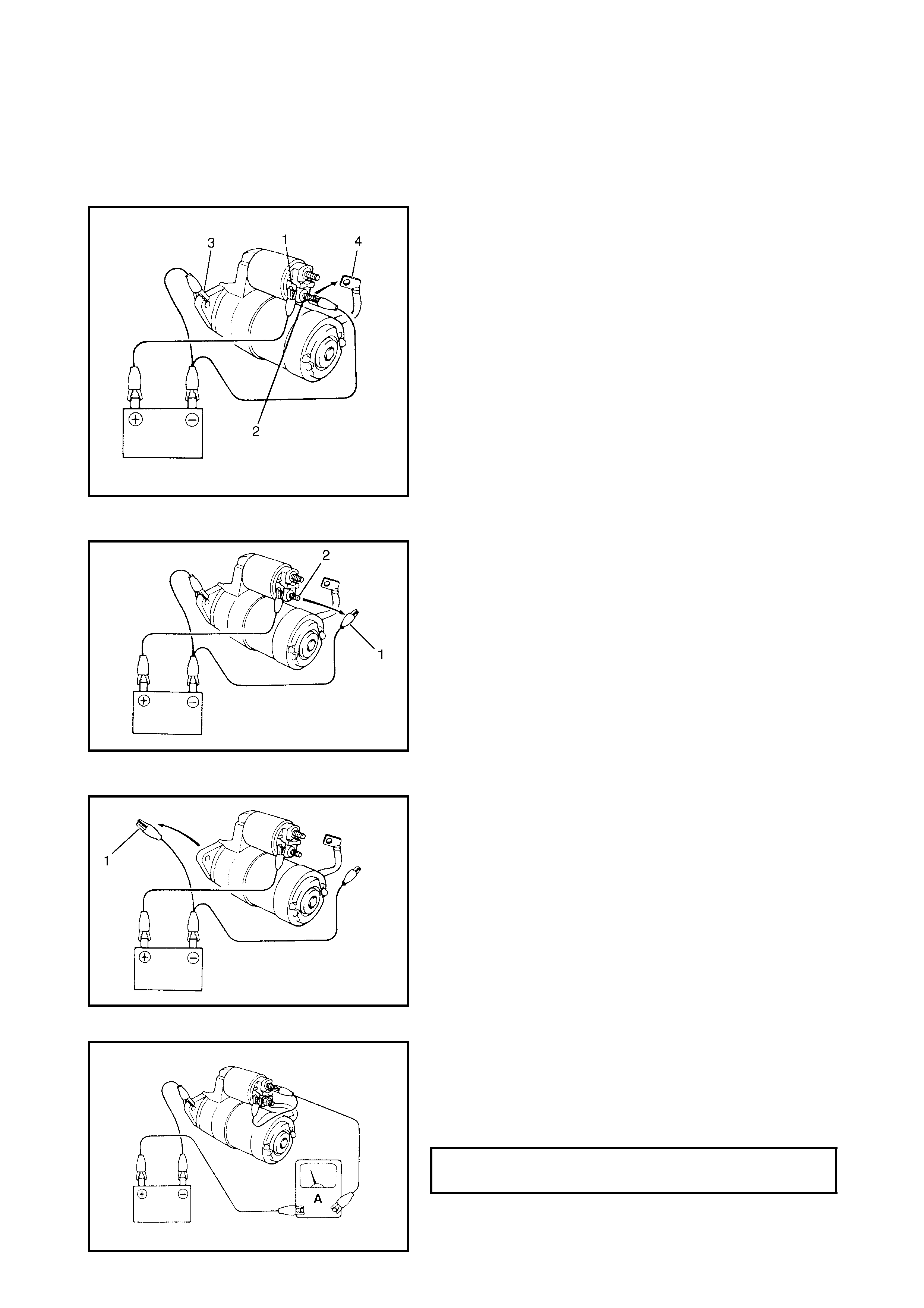
2.2 PERFORMANCE TEST
CAUTION: Each test must be performed within 3 - 5
secon ds to avo id the coil from burning out.
PULL-IN TEST
Connect the battery to the magnetic switch as shown in the
figure, with the positive lead to terminal-S (1) and the nega-
tive leads to termi nal-M (2) and star t ing motor body (3).
Check that the plunger and pinion mov e outward.
If t he plunger and pinion do n’t m ove, replace the magnetic
switch.
NOTE: Before testing, disconnect the lead wire, switch to
motor, (4) fr o m termin a l - M (2).
HOLD-IN TEST
While still connected (as a bove), with the pl unger out, dis-
con nect the negative le ad (1) from termin al M (2).
Check that the plunger and pinion remain out.
If the plunger and pinion return inward, replace magnetic
switch.
PLUNGER AND PINION RETURN TEST
Disconnect the negative lead (1) from the starting motor
body.
Check that the plunger and pinion return inward.
If th e plu nger an d pinion don’t ret urn, replace the m agnet ic
switch.
NO-LO AD PERFORMANCE TEST
Connec t the batter y and the ammeter t o the st art ing motor
as shown in the figure.
Check that the star ting motor rotates smoot hly and stead ily
with the pinion moving out. Check that the ammeter indi-
cates the specified current.
SPECIFIED CURRENT @ 11 VOLTS
(NO-LOAD PERFORMANCE TEST) 90 A MAX
3 . ON-VEHICLE SERVICE
3.1 STARTING MOTOR
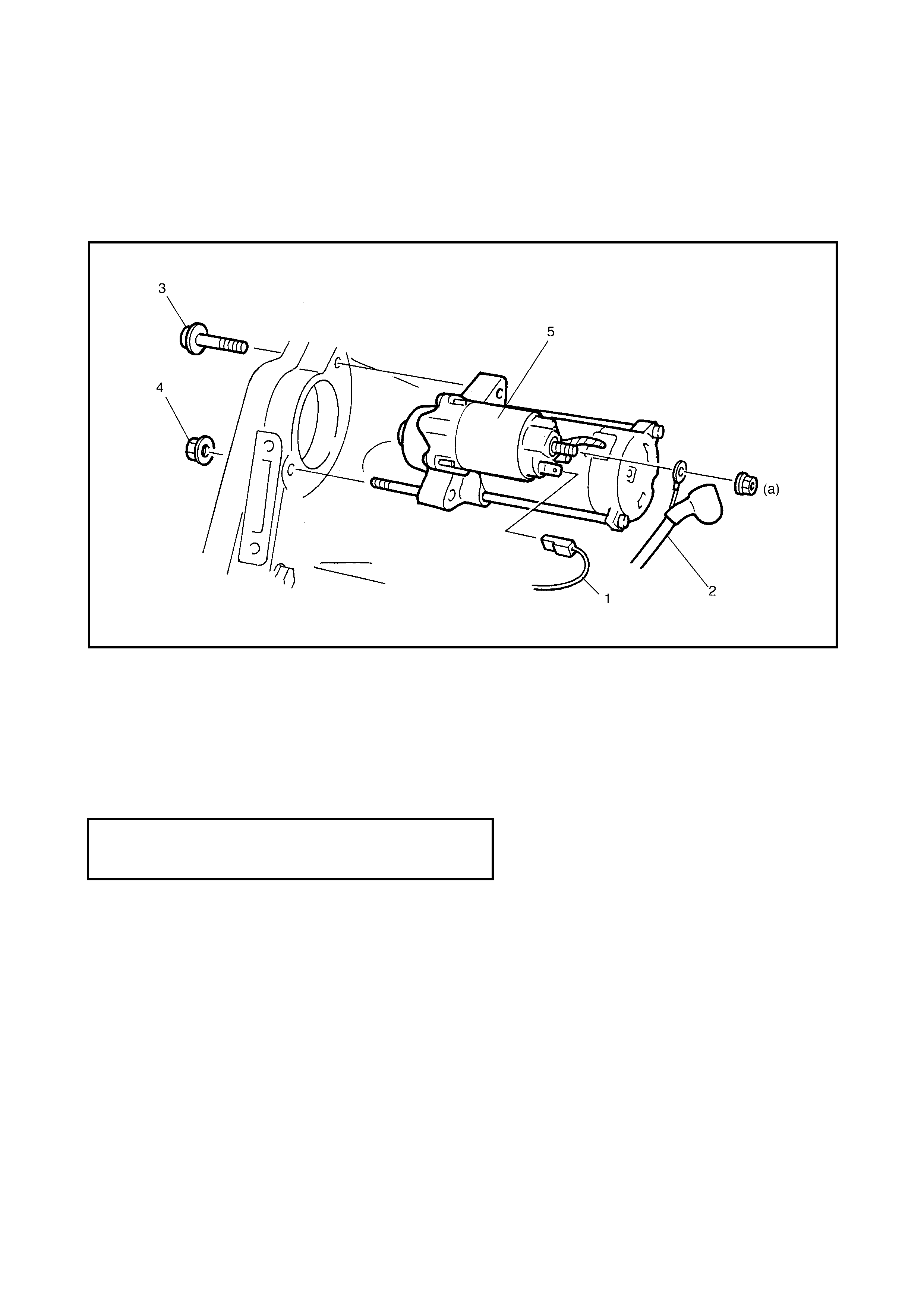
REMOVAL
1. Disconnect the nega tive (–) batter y lead from the battery.
2. Disconnect the magnet ic switch lead wire (1) and the battery cable (2) from the starting motor term ina ls.
3. Remov e the starting motor mount bolt (3) and nut (4).
1. Remov e the starting motor (5).
INSTALLATION
Reverse the removal procedure.
STARTING MOTOR BATTERY CABLE
NUT (a)
TORQUE SPECIFICATION 10 Nm
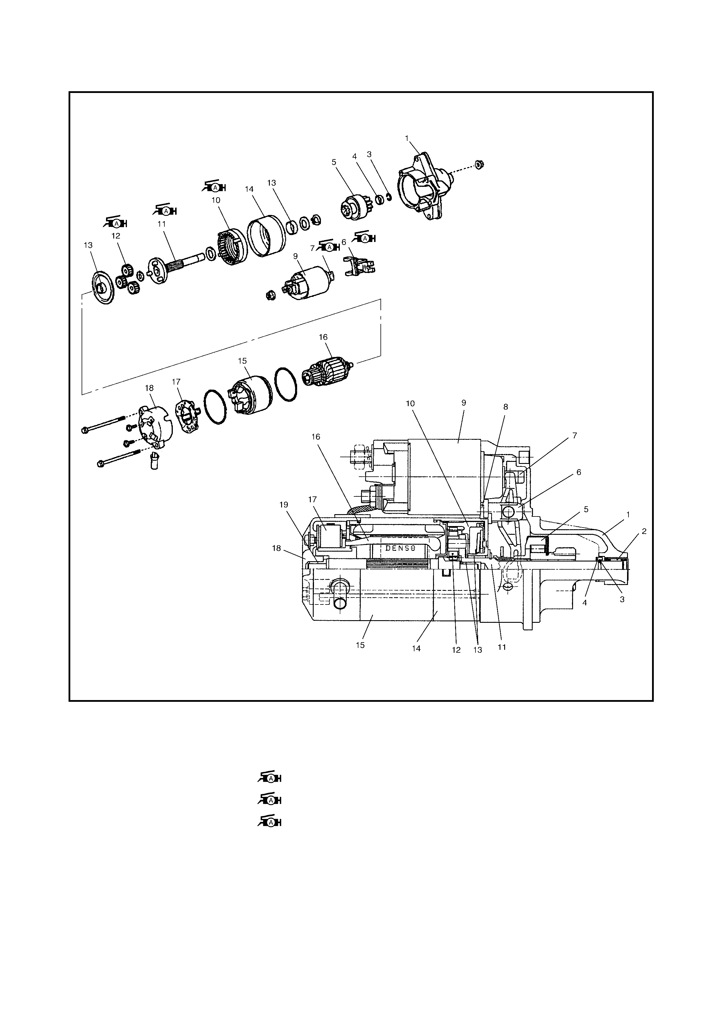
DISASSEMBLY AND REASSEMBLY
Legend
1. Front housing 8. Seal rubber 14. Centre bearing with shock
absorber
2. Needle bearing 9. Magne tic swi tch
3. Snap ring 10. Internal gear 15. Yoke
4. Pinion stop ring 11. Planetary carrier shaft 16. Ar ma ture
5. Over-running clutch 12. Planetary gear 17. Bru sh holder
6. Leve r 1 3. Oille ss bearing 18. Rear bracket
7. Plunger 19. Rear bush

4. SPECI FICATION
5. REQUIRED SERVICE MATERIAL
Voltage 12 volts
Out put 1.0 kW
R ating 30 seconds
D irection of rotation Clockwise as viewed from pinion side
Br us h length Standard: 14.0 mm (0.55 in.) Limit: 9.0 mm (0.35 in.)
Number of pinion teeth 8
Performance Condition Rating
Around at 20°C
(68°F) No l oad ch aracteri stic 11.5 V 90 A maxim um
3,000 r pm minimum
Load characteristic 8.7 V
230 A 6.9 Nm minimum
1130 rpm minimum
Locked rotor current 2.5 V 325 A maximum
8.2 Nm minimum
Magnetic switc h operating v ol tage 8 vol ts maximum
Material Recommend ed product Use
Lithium grease Lithium Grease • Plunger
• Pinion drive lever
• Internal gear
• Planetary carrier shaft
• Planetary gear
•Ball