
SECTION 7A - MANUAL TRANSAXLE
1. GENERAL DESCRIPTION
1.1 CONSTRUCTION AND SERVICING
2. DIAGNOSIS
3. ON-VEHICLE SERVICE
3.1 OIL CHANGE
3.2 DIFFERENTIAL SIDE OIL SEAL
Replacement
3.3 GEAR SHIFT CONTROL LEVER AND
CABLE
Removal
Installation
3.4 VEHICLE SPEED SENSOR (VSS)
Removal
Installation
4. UNIT REPAIR OVERHAUL
4.1 TRANSAXLE UNIT COMPONENT
IDENTIFICATION
4.2 TRANSAXLE CASE COMPONENT
IDENTIFICATION
4.3 INPUT AND COUNTER SHAFT
COMPONENT IDENTIFICATION
4.4 GEAR SHIFTER COMPONENT
IDENTIFICATIO
4.5 DIFFERENTIAL COMPONENT
IDENTIFICATION
4.6 TRANSAXLE UNIT
Removal
Installation
4.7 UNIT DISASSEMBLY
Fifth Gears
Gear Shifter, Input Shaft and
Counter Shaft
Right Case
4.8 SUB ASSEMBLY SERVICE
Right Case
Left Case
Input Shaft Assembly
Counter Shaft Assembly
Gear Shifter
Differential Assembly
4.10 UNIT ASSEMBLY
Differential to Left Case
Fifth Gears
Gear Shift and Select Shaft
Assembly
5. REQUIRED SERVICE MATERIAL
6. SPECIAL TOOLS
WARNING:
For vehicles equipped with Supplement Restraint (Airbag) System
• Service on and around the airbag system components or wiring must be performed only by
an authorised HOLDEN retailer. Refer to Section 10B AIRBAG SYSTEM-COMPONENTS AND
WIRING LOCATION VIEW in GENERAL DESCRIPTION in order to confirm whether you are
performing service on or near the airbag system components or wiring. Please observe all
WARNINGS and SERVICE PRECAUTIONS, refer to Section 10B ON-VEHICLE SERVICE before
performing service on or around the airbag system components or wiring. Failure to follow
WARNINGS could result in unintentional activation of the system or could render the system
inoperative. Either or these two conditions may result in severe injury.
• Technical service work must not be started for at least 90 seconds after the ignition switch is
turned to the “LOCK” position and the negative cable is disconnected from the battery. Oth-
erwise, the system may be activated by reserve energy in the Sensing and Diagnostic Module
(SDM).
Techline

1. GENERAL DESCRIPTION
1.1 CONSTRUCTION AND SERVICING
The transaxle provides five forward speeds and on e reverse speed by means of three synchronisers and the
input shaft, the countershaft and the reverse gear shaft. All forward gears are in constant mesh, and the
re v e rs e uses a sliding idler gear arrangement.
The low spee d s ync hroniser i s mo unt ed on the count er shaf t and engages with th e count er shaf t first ge ar or
second gear, while the high speed synchron iser is done on the input shaft and engages with the input shaft
third gear or fourt h gear.
The fifth speed synchroniser on the input shaft is engaged with the fifth gear mounted on the input shaft.
The double cone synchronizing mechanism is provided to the second gear synchrome sh device for high per-
form ance of shifting to second gear.
The countershaft turns the final gear and the differential assembly, thereby turning the front drive shafts which
are attached to the front wheels.
The transf er assembly is attached to the right side of the transaxle differential output.
For servicing, it is necess ary t o use genui ne s eala nt or its equivalent on the mating surfaces of the aluminum
transaxle case. The case fastening bolts must be tightened to the specified torque by means of a torque
wrench. It is also imp or t ant that al l p arts are thoroughl y cleane d wi th cleani ng f luid and ai r dried befo re reas-
sembling.
Further c are must be t aken to adjust t he preload of t he co unter s haft taper roll er bearings. New sy nchroniser
rings are prohibited from being lapped with respectiv e gear cones by using lapping compound bef ore they are
assembled.
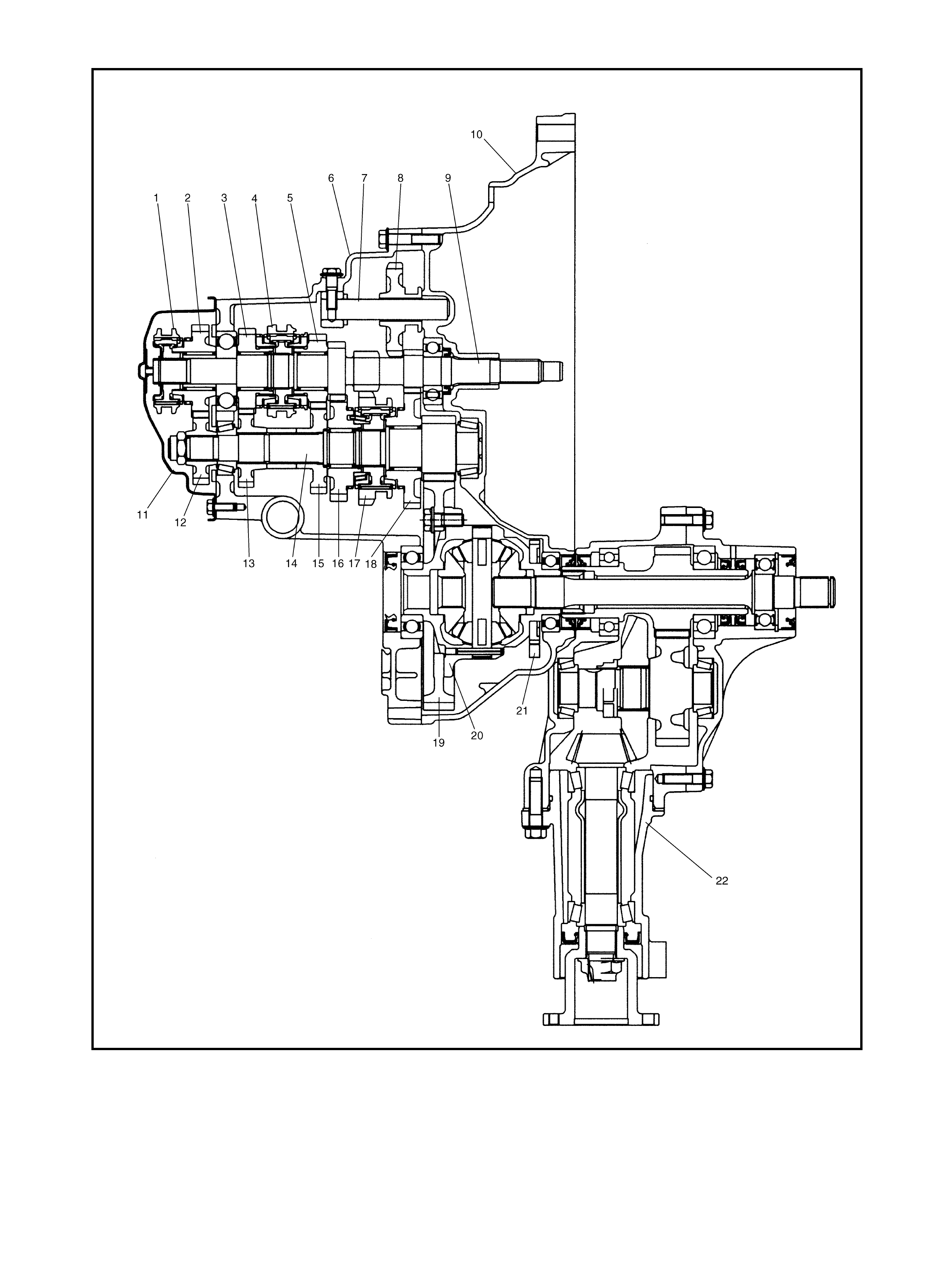
Legend
1. 5th speed sleeve & hub 9. I nput shaft 17. Low speed sleeve & hub
2. Input shaft 5th gear 10. Right case 18. Count ers haft 1st gear
3. Input sh aft 4th gear 11. Side cover 19. Fina l gear
4. H igh speed sleeve & hub 12. Countershaft 5th gear 20. Differential case
5. Input shaft 3rd gear 13. Countershaft 4th gear 21. Vehi cle spe ed sensor
6. Left case 14. Countershaft 22. Transf er assembly
7. R everse gear shaft 15. Countershaft 3rd gear
8. R everse idler gear 16. Countershaft 2nd gear

2. DIAGNOSIS
Condition Possible Cause Correction
Gears slipping out of
mesh
Incor rectly adjusted gear shift select control
cables. Adjust
Worn shift fork shaft. Replace
Worn shift fork or synchronis er sleeve. Replace
Weak or damaged locating springs. Replace
Worn bearings on input shaft or countershaft. Replace
Worn chamfered teeth on sleeve and gear. Replace sleeve and gear.
Hard shifting Incorrectly adjusted gear shift select control
cables. Adjust
Inadequate or insuffi cient lubricant. Replenish
Improper clutch pedal free travel. Adjust
Distorted or broken clutch disc . Repl ace
Damaged clutch pressure plate. Replace clutch cover
Worn synchroniser ring. Replace
Worn chamfered tooth on sleeve or gear. Replace sleeve or gear.
Worn gear shift select control cables joint. Replace
Distorted shift sha ft. Repl ace
Noise Inadequate or insufficient lubricant. Replenish
Damaged or worn bearing(s). Replace
Damaged or worn gear(s). Replace
Damaged or worn synchroniser parts. R eplace
3. ON-VEHICLE SERVICE
CAUTION: Do not reuse circlip, spring pin, E-ring, oil
seal, gasket, self locking nut and specified parts.
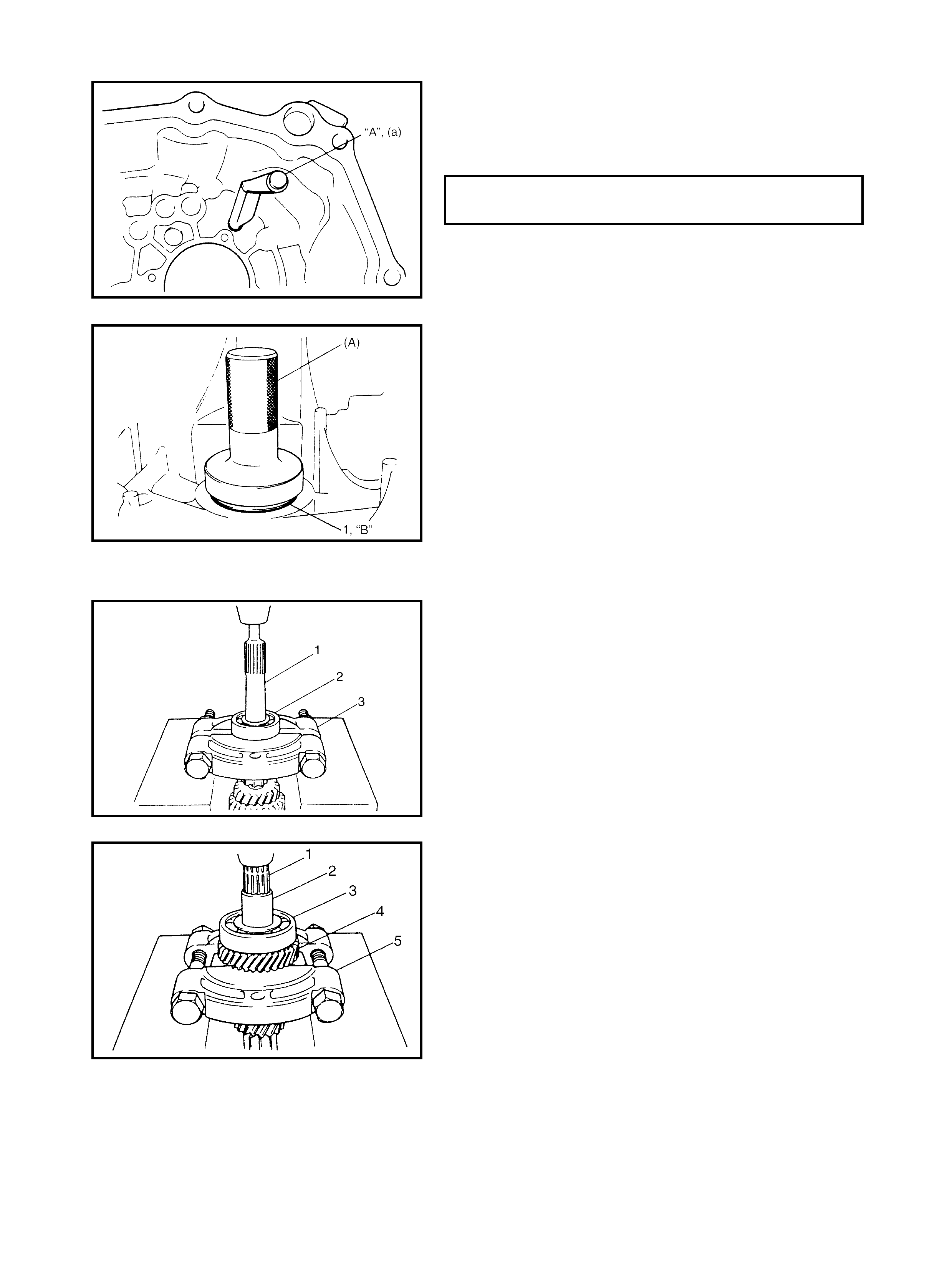
3.1 OIL CHANGE
1. Before changing or inspecting the oil, raise the vehicle
on a hoist.
2. Check the oil level and the transaxle for leakage.
If a leakage exists, repair it.
3. Remove the drain plug (2) and drain the old oil.
4. Remove the oil level filler plug (3) located near the left
hand drive shaft (1). This will assist in the drainage.
5. Refill the transaxle with the new specified oil up to the
level of the oil level filler plug.
6. Apply sealant to the thread of the drain plug and the oil
level filler plug. Torque them as specified below.
“A”: Sealant - Three Bond No. 1215
NOTE:
• It is highly recommended to use API GL-4 75W-90
gear oil.
• Whenever a vehicle is hoisted for any service work
other than an oil change, be sure to check for oil leak-
age.
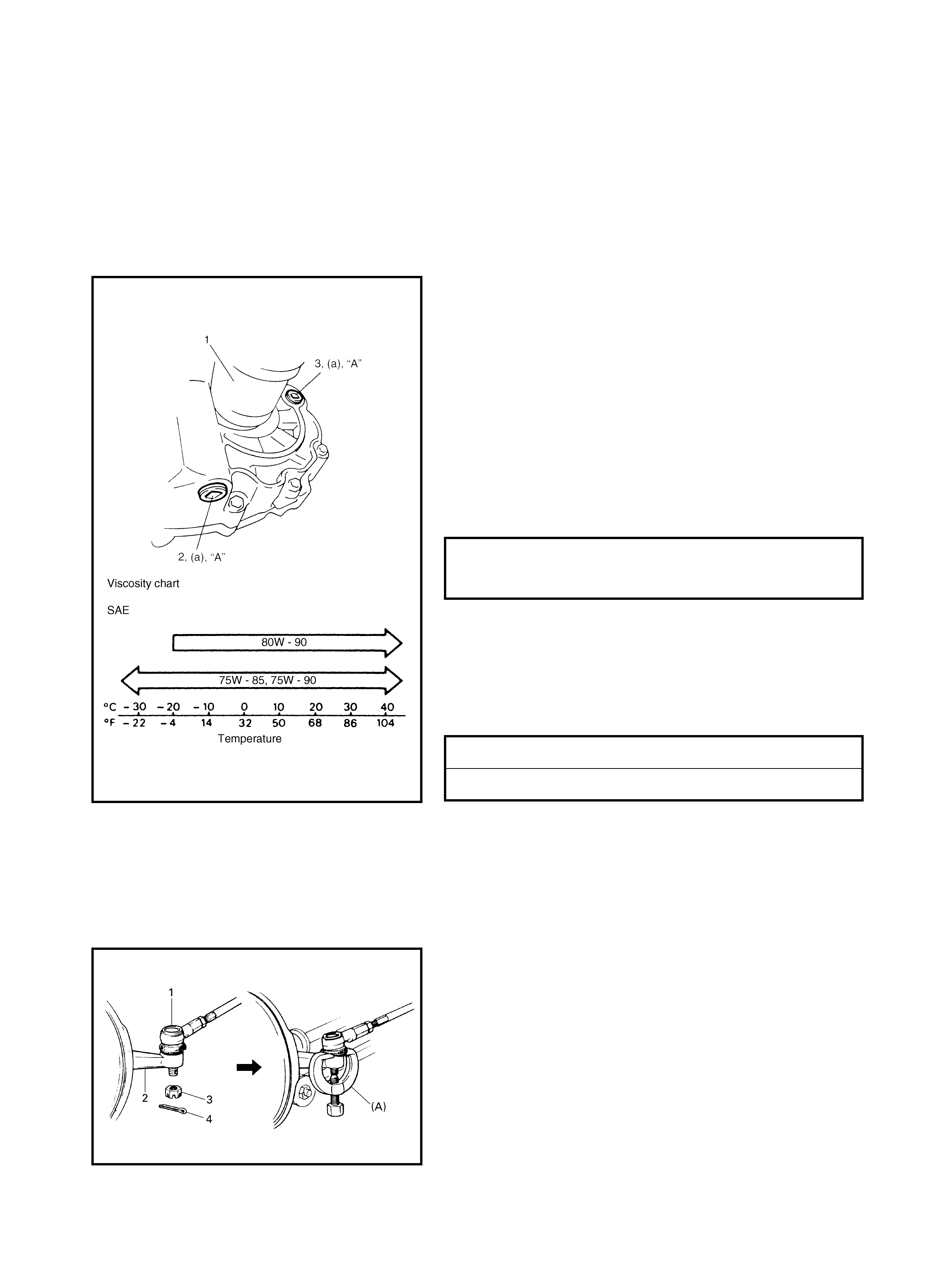
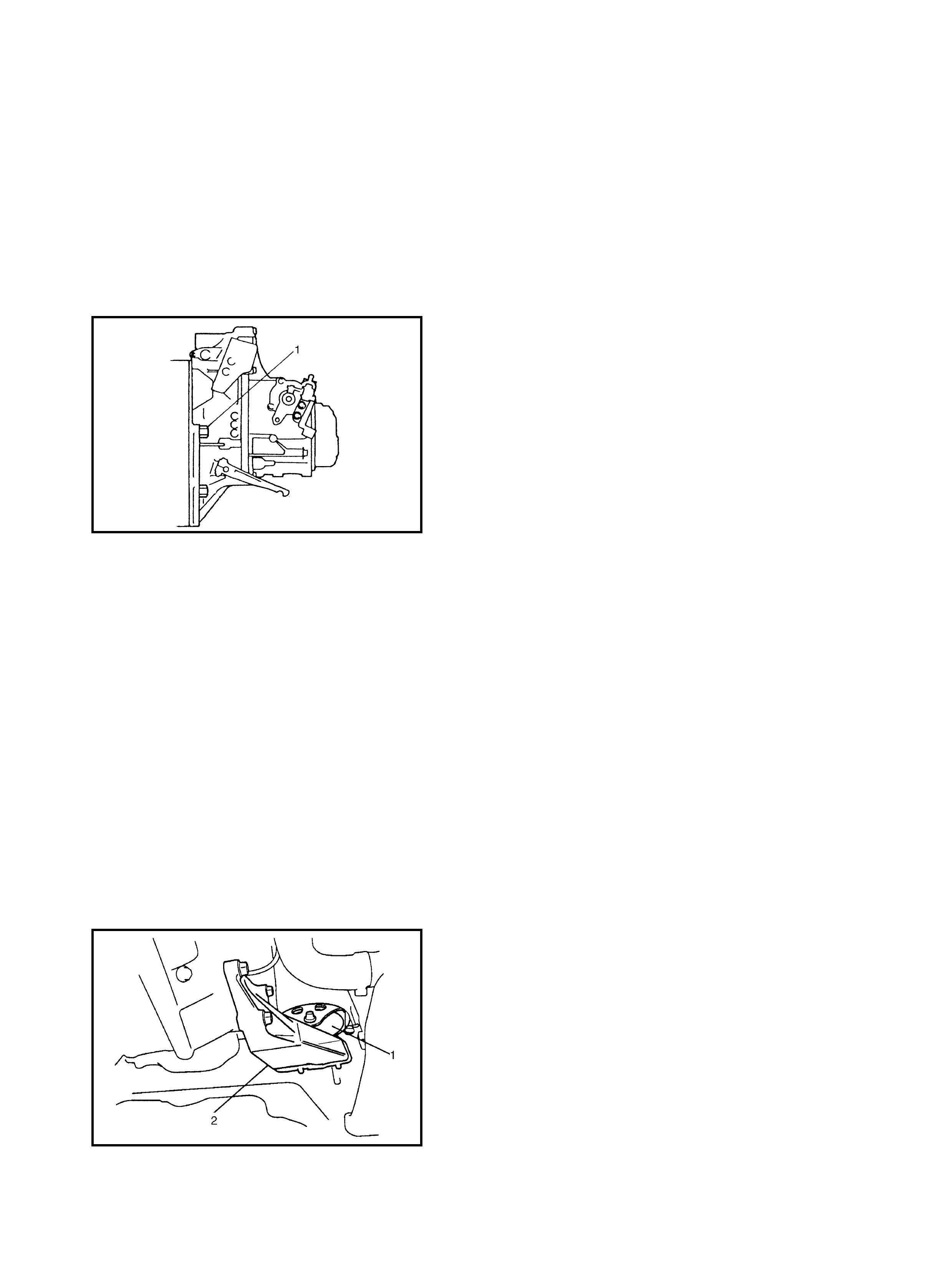
3.2 DIFFERENTIAL SIDE OIL SEAL
REPLACEMENT
1. Raise the vehicle and drain the transaxle and the
transfer oil, refer to 3.1 OIL CHANGE.
2. Remove the wheel, then to remove the tie-rod end (1)
remove the split pin (4) and the castle nut (3).
3. Disconnect the tie-rod end from the knuckle (2) using
special tool 09913-65210 (A).
4. Remove the two stabiliser mounting brackets from the
vehicle body refer to Section 3D, 3.2 STABILISER BAR
AND/OR BUSHINGS.
TRANSAXLE OIL LEVEL FILLER PLUG
AND DRAIN PLUG
TO RQUE SPECIFICATION a: 21.0 Nm
TRANSAXLE OIL API GL-4
TRANSAXLE OIL CAPACI TY 2.2 l it res
5. Remove the ball joint bolt and then separate the sus-
pension arm from the knuckle.
6. Separate the transfer from the transaxle assembly,
refer to Section 7D, 4.1 TRANSFER UNIT.
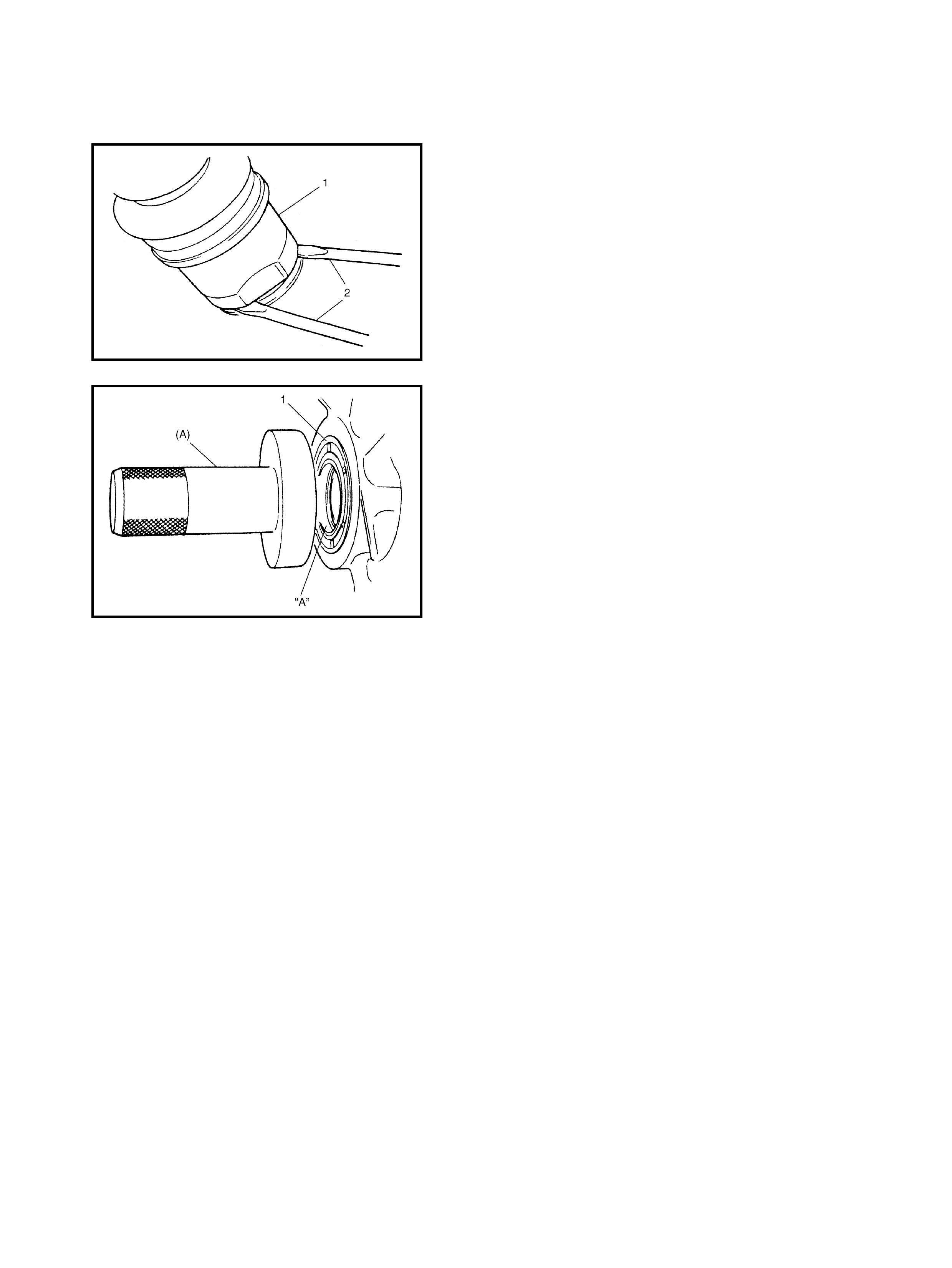
7. Remove the drive shaft joint (1) using two large size
screwdrivers (2), to release the snap ring fitting of the
joint spline at the differential side. Pushing the knuckle
portion outward, detach the drive shaft at the differen-
tial side.
8. Remove the oil seal (1).
9. Using special tool 09913-75510 (A) for left or right
hand and a hammer, install a new oil seal until it
becomes flush with the case surface.
NOTE: When installing the oil seal, face the spring side
inward.
10. Apply grease “A” to the oil seal lip. Check the drive
shaft for smoothness where the oil seal contacts.
“A”: Lithium grease
11. Insert the transfer into the transaxle, refer to
Section 7D, 4.6 TRANSFER UNIT.
12. Insert the drive shaft joint into the differential gear.
CAUTION:
• Be careful not to scratch the oil seal lip while inserting
the drive shaft joint.
• Make sure to seat the snap ring when inserting the
drive shaft joint fully.
• Only use your hands when inserting the joint boot as a
hammer will cause damage.
13. Connect the ball joint with the knuckle and fasten with a
bolt, to specification, refer to Section 3D, 3.3 WHEEL
HUB AND STEERING KNUCKLE.
14. Connect the tie-rod end with the knuckle and fasten
with a new nut, to the specified torque, refer to Section
3D, 3.3 WHEEL HUB AND STEERING KNUCKLE.
15. Install the stab iliser mounti ng brackets, an d fasten the
bolts to the specified torque, refer to Section 3D,
3.2 STABILISER BAR AND/OR BUSHINGS.
16. Replenish the transaxle oil and transfer oil as specified,
refer to 3.1 OIL CHANGE in this Section, then check
the oil seal for leakage.
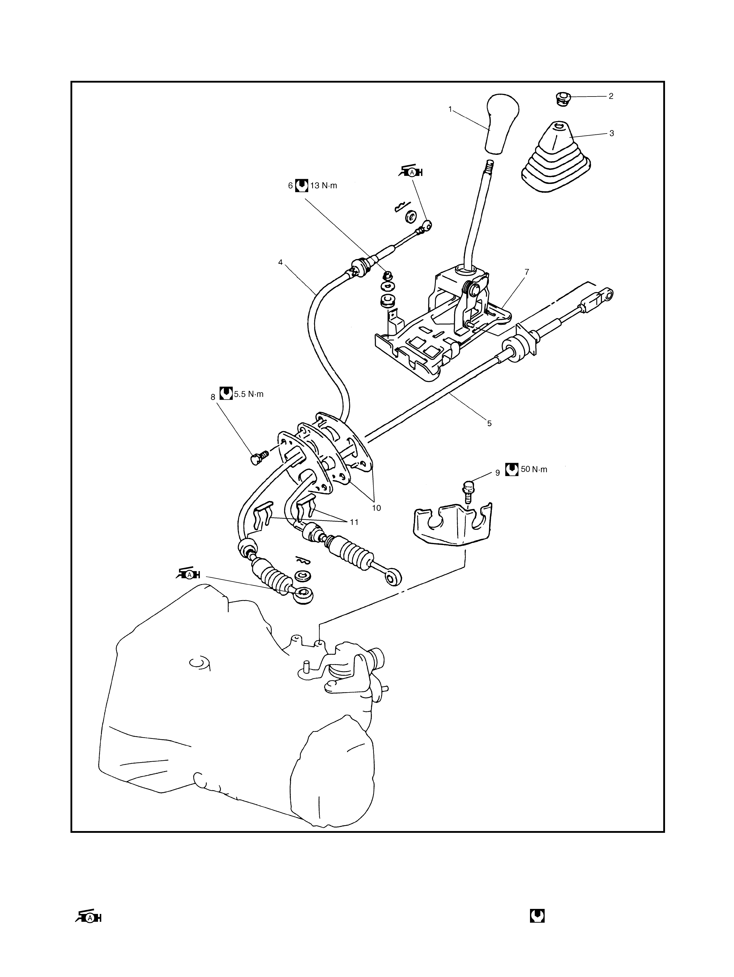
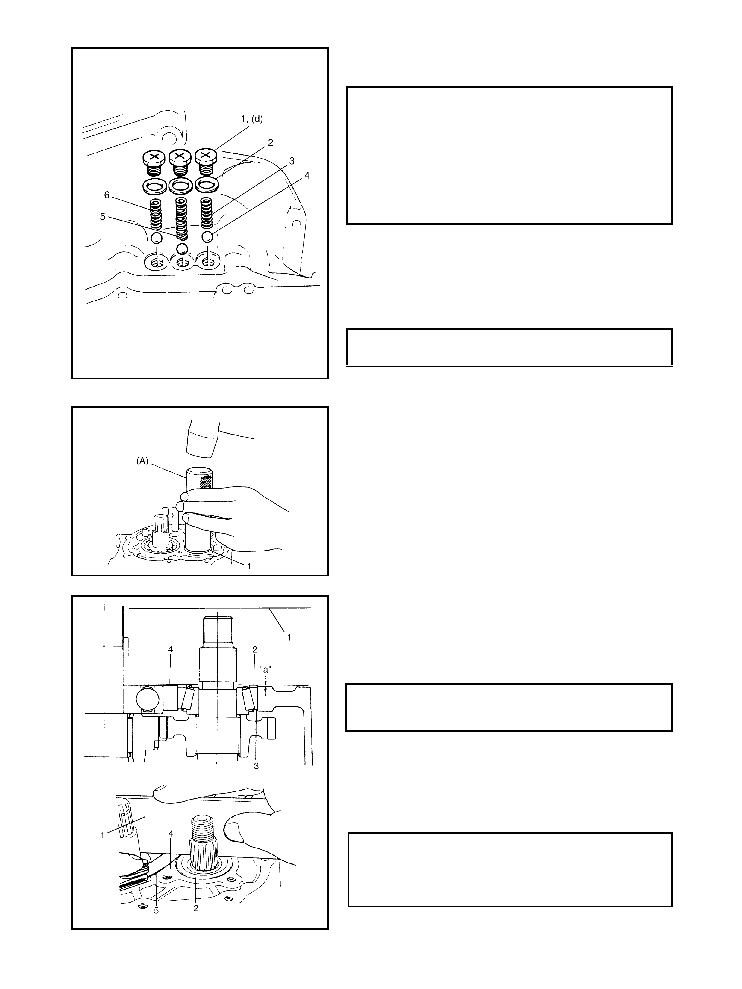
3.3 GEAR SHIFT CONTROL LEVER AND CABLE
Legend
1. Gear shift control le v er knob 5. Gear select control cable 9. Cab l e brack et bolt
2. Lever boot holder 6. Gear shift control cable
guide nut 10. Cable grommet
3. Gear shift le ver boot 11. E-ring
4. Gear shift control cable
: Apply Lithium grease to connecting
portion of gear shift control cable
7. Gear shift control le ver
assembly Tightening torque
8. Cable mou nting bolt
REMOVAL
1. Remov e the console.
2. Disconn ect the gear shift and the select cont rol cables
from the gear shift control lever assembly.
3. Remove the gear sh ift control cable guide nuts and the
gear shift lever assembly from the body.
4. Disconnect the shift and the select cables from the
transaxle.
5. Remove the E-rings, the cable grommet and the cable
clamp.
6. Remove the shift and the select cables from the body.
INSTALLATION
Reinstallation is the reverse of the removal noting the fol-
lowing:
• Appl y grease to the turning or sliding port ions.
• Tighten all retaining bolts and nuts to the correct t orque
specifications.
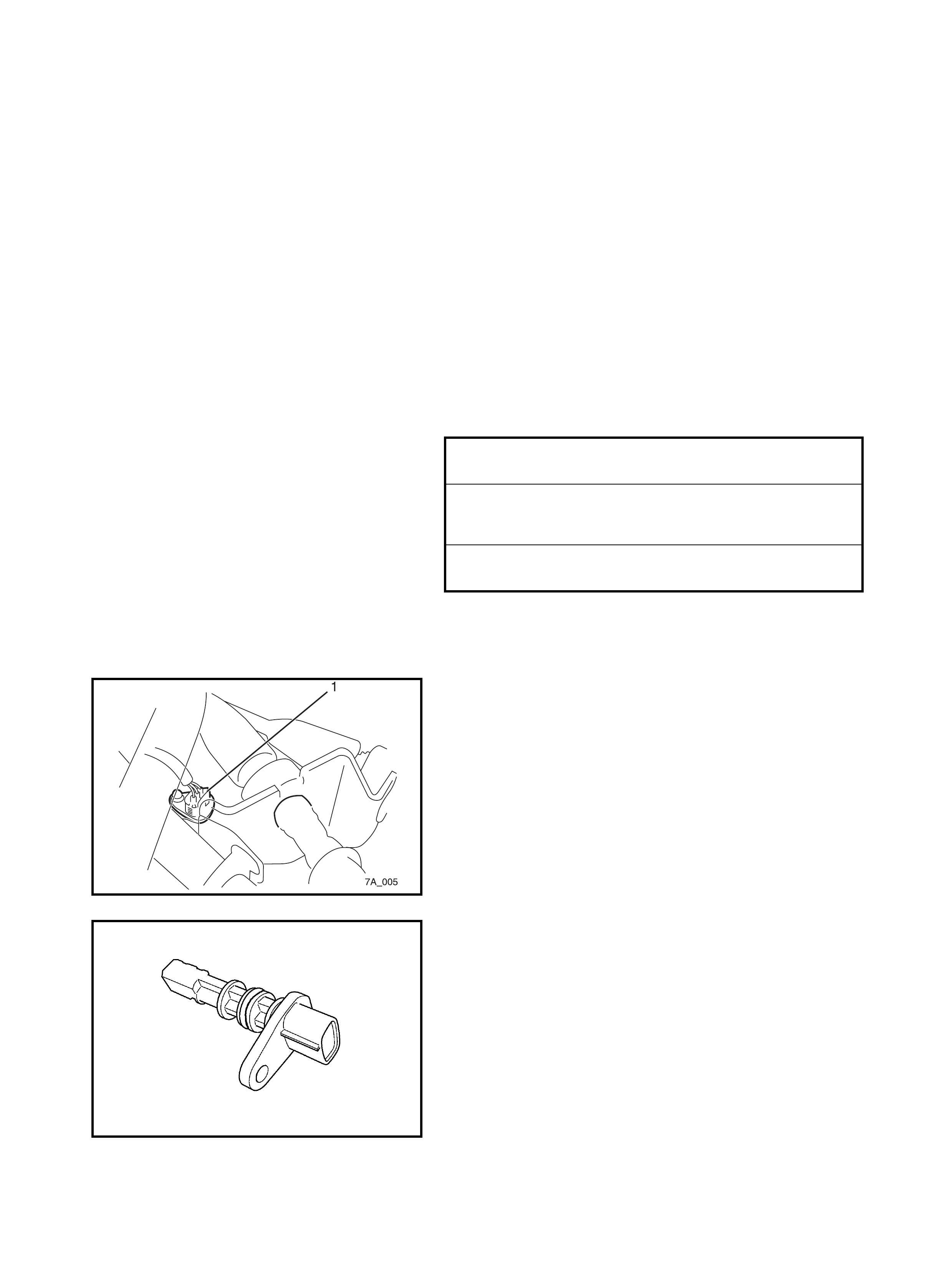
3.4 VEHICLE SPEED SENSOR (VSS)
REMOVAL
1. Disconnect the negative cable at the battery.
2. Discon nect the VSS connector (1).
3. Remove the VSS.
CABLE MOUNTING BOLT
TORQUE SPECIFICATION 5.5 Nm
GEAR SHIFT CONTR O L
CABLE GUIDE NUT
TORQUE SPECIFICATION 13.0 Nm
CABLE BRACKET BOLT
TORQUE SPECIFICATION 50.0 Nm
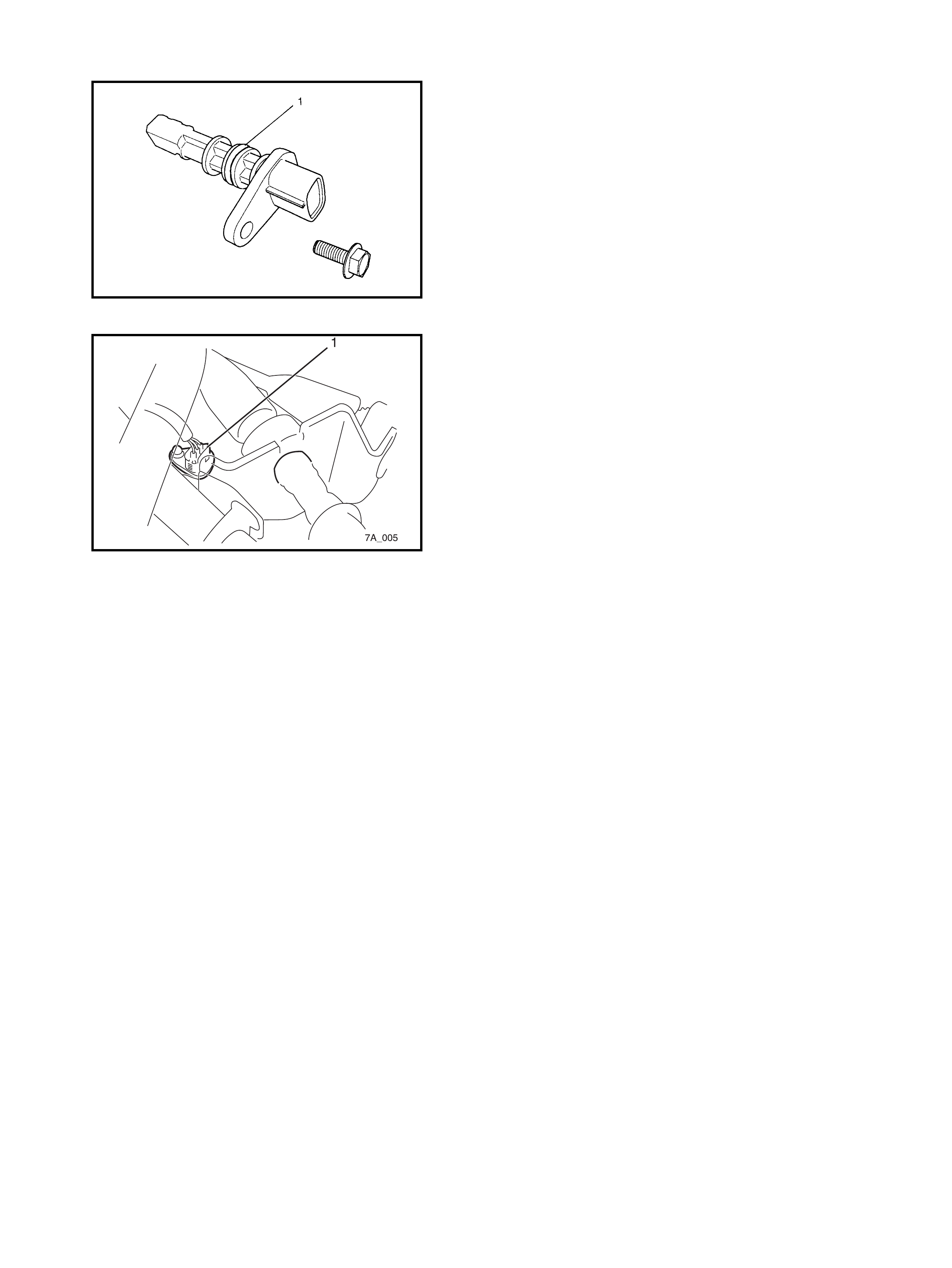
INSTALLATION
1. Check the O-ring (1) and the VSS surface for any
flaws. Apply Lithium grease to the O-ring and install the
VSS into the transaxle and tighten securely. For
inspection and testing refer to Section 6, 2.22 DTC
PO500 (DTC No16) VEHICAL SPEED SENSOR (VSS
MALFUNCTION)
2. Connec t the negative cable at th e batter y.
3. Co nne ct the VSS connector (1).
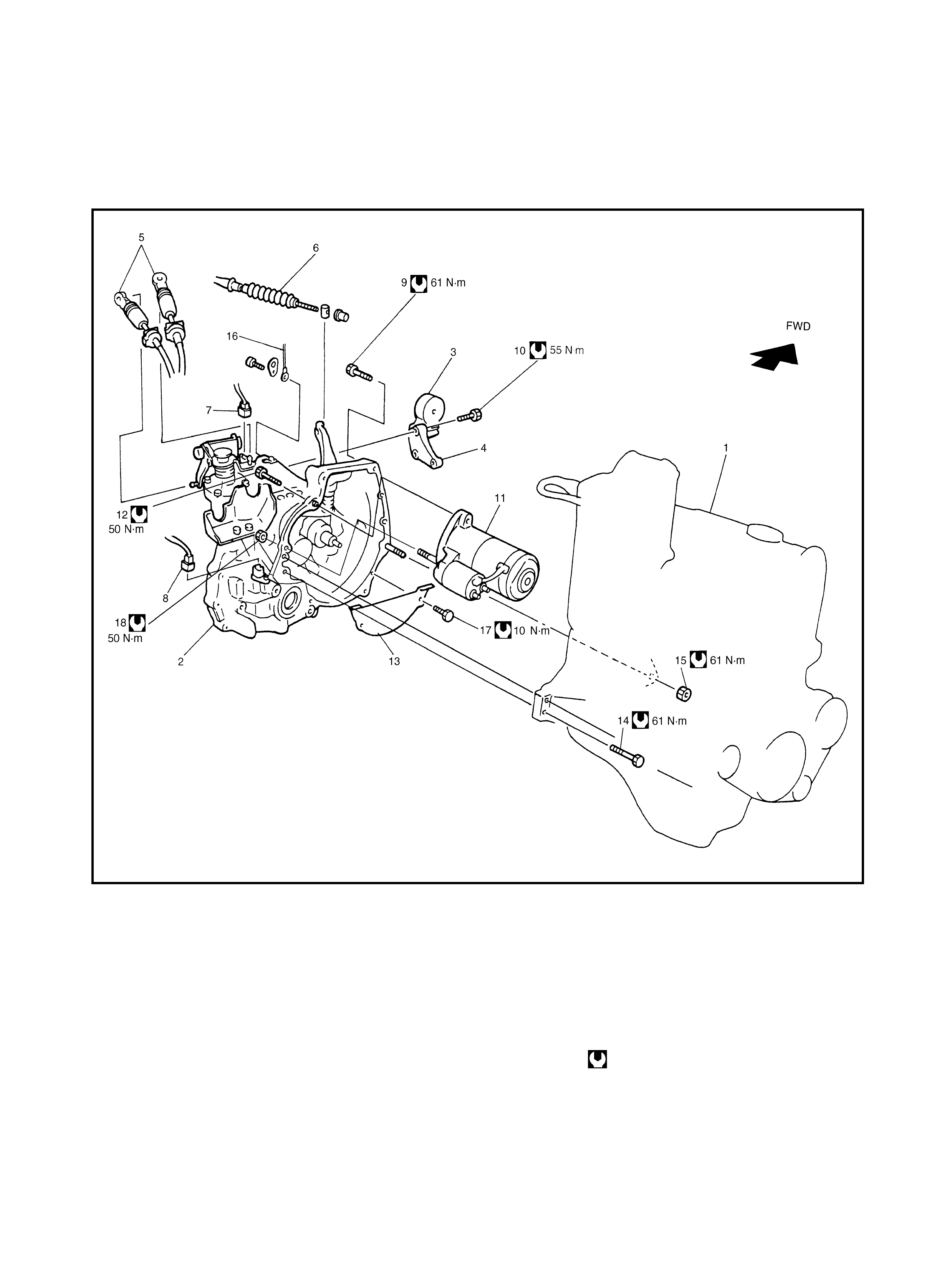
4. UNIT REPAIR OVERHAUL
4.1 TRANSAXLE UNIT COMPONENT IDENTIFICATION
Legend
1. Eng ine 7. B ackup light switch connec-
tor 13. Clutch housing lower plate
2. Transaxle 14. Transaxle to engine bolts
3. Eng ine left mount ing 8. V S S connect or 15. Transaxle to engine nut
4. Eng ine left mount ing
bracket 9. Transaxle to engine bolts 16. Ground c able
10. Engine left mounting bracket
bolts 17. Clutch housing lower plate bolts
5. Shift & select control
cables 18. Starting motor nut
11. S ta rting mo tor Tightening torque
6. C lutch cable 12. S ta rting mo tor bolt
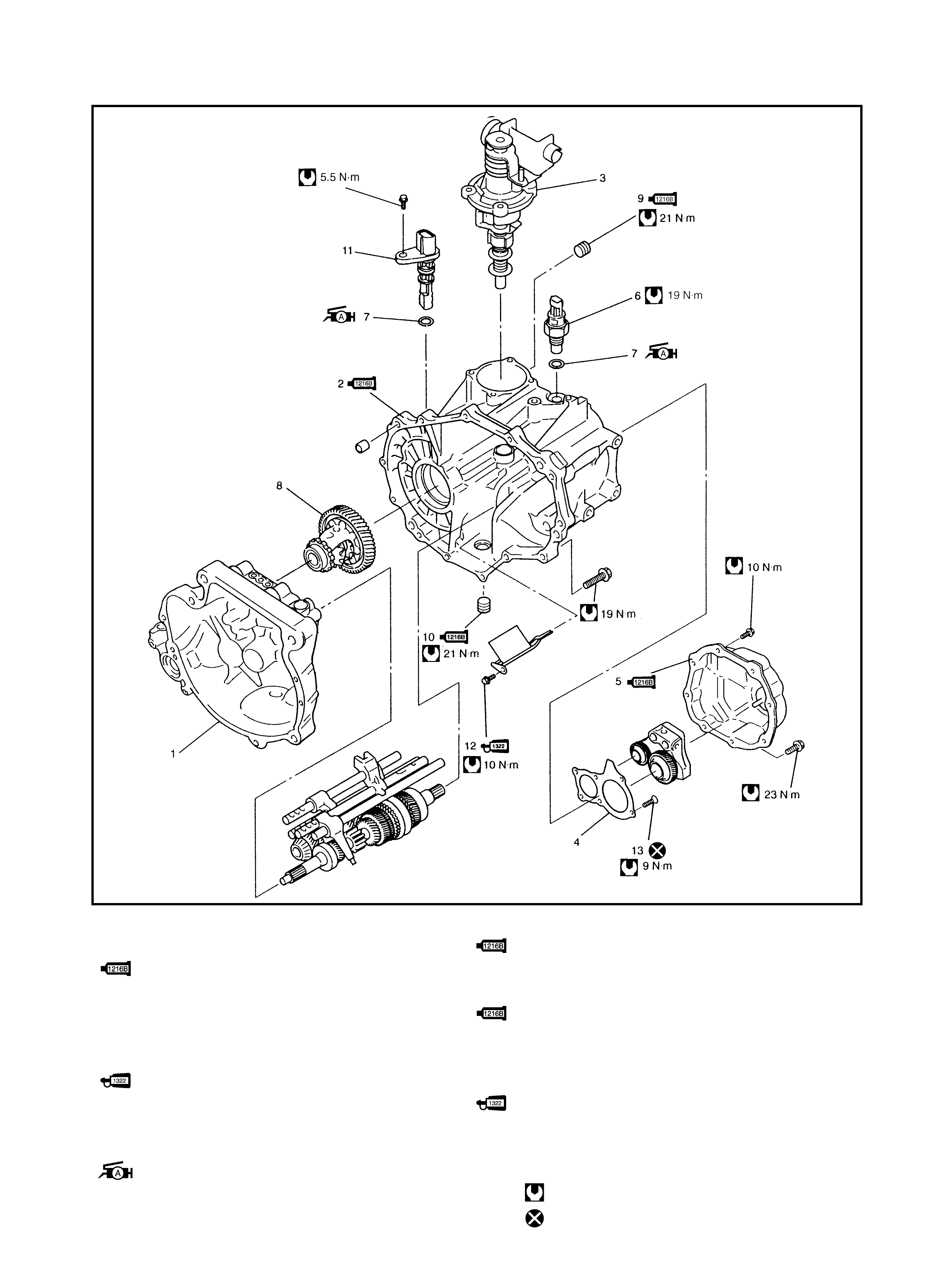
4.2 TRANSAXLE CASE COMPONENT IDENTIFICATION
Legend
1. Transaxle right case 9. Oil level/filler plug
: Apply sealant Three Bond No. 1 215 to all
around thread par t of plug
2. Transaxle left case
: Apply sealant Three Bond No . 1216B to
mating surface of l eft case and right case. 10. Oil gutter bolt
: Apply sealant Three Bond No. 1216B to
all around thread part of plug
3. Gear shifter assembly
4. Transaxle left case plate
5. Transaxle side cov er
: Apply sealant Three Bond No . 1216B to
mating surface of side cover and left case
11. VSS
12. Oil gutter bolt
: Apply thread lock 1322 to all
around thread par t of bolt
6. Backup light switch
7. O-ring
: Apply Lithium grease to O-ring 13. Left case plate screw
Tightening torque
8. Differential assembly Do not reuse.
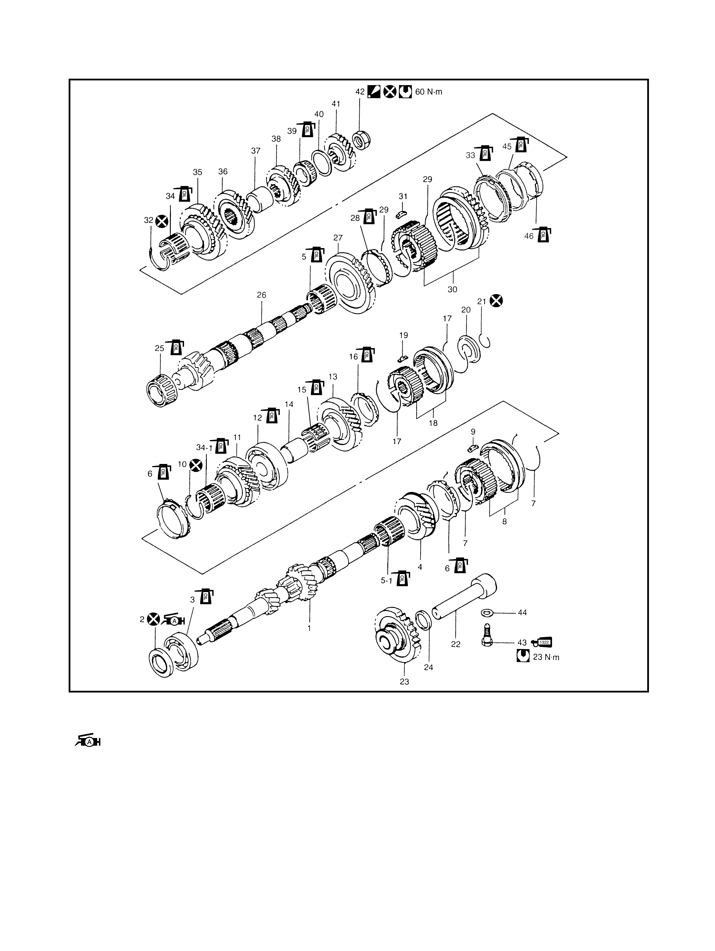
4.3 INPUT AND COUNTER SHAFT COMPONENT IDENTIFICATION
Legend
1. Input sha ft 27. Countershaft 1st gear
2. Oil seal
: Apply Lithium grease to oil seal lip 28. 1st gear synchroniser ring
29. Low speed sync hroniser spring
3. Input sha ft right bearing 30. Low speed sleeve & hub
4. Input shaft 3rd gear 31. Low speed synchroniser ke y
5. Needle bearing (resin cage type) 32. Circlip
5-1. Needle bearing (resin cage type) 33. 2nd gear synchroniser outer ring
6. High speed synchroniser ring 34. Needle bearing
(separated steel cage type)
7. High speed synchroniser spring
8. High speed sleeve & hub 34-1. Needle bearing (steel cage type)
Countershaft 2nd gear
9. High speed synchroniser key 35.
10. Circlip 36. Countershaft 3rd gear
11. Input shaft 4th gear 37. 3rd & 4th gear spacer

12. Input shaft left bearing 38. Countershaft 4th gear
13. Input sha ft 5th gear 39. Countershaft left bearing
14. 5th gear spac er 40. Bearin g set shim
15. 5th gear needle bearing
(separated steel cage type) 41. Countershaft 5th gear
42. Countershaft nut
: After tightening nut to specified
torque, stake nut securely
16. 5th speed synchroniser ring
17. 5th synchroniser spring
18. 5th speed sleeve & hub 43. Reverse s haft bolt
: Apply thread lock cem ent 1322 to
thread of bolt.
19. 5th synchroniser key
20. 5th synchroniser hub plate
21. Circlip 44. Washer
22. Reverse gear shaft 45. Centre cone
23. Reverse idler gear 46. 2nd gear synchroniser inner ring
24. Reverse shaft washer Tightening torque
25. Countershaft right bearing Do not reuse
26. Countershaft Apply transaxle oil
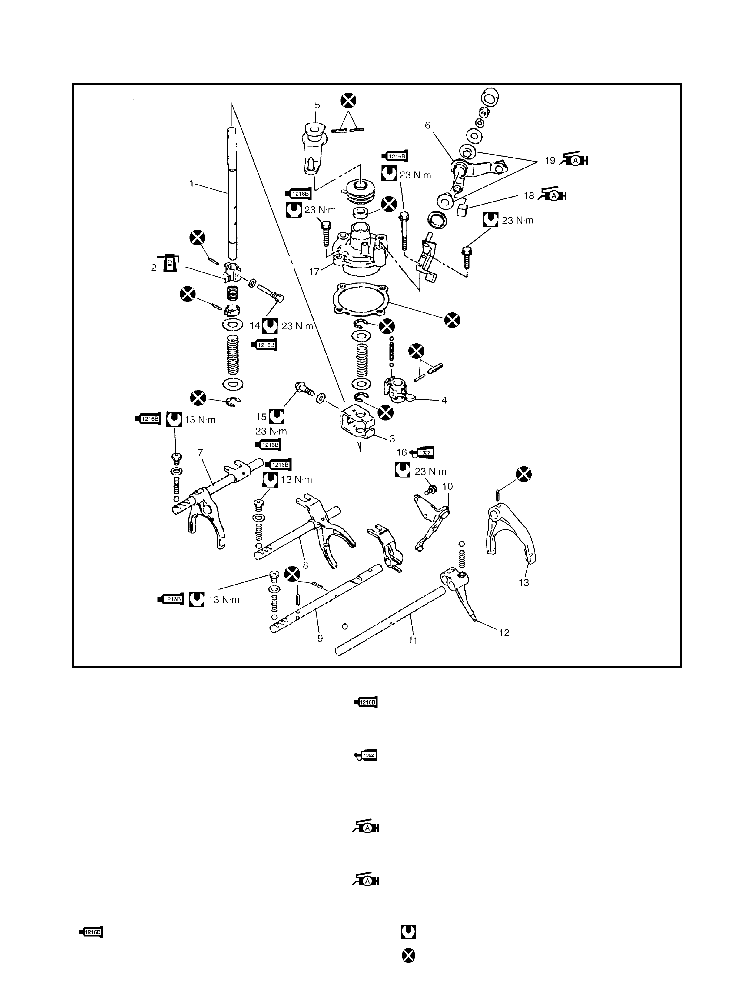
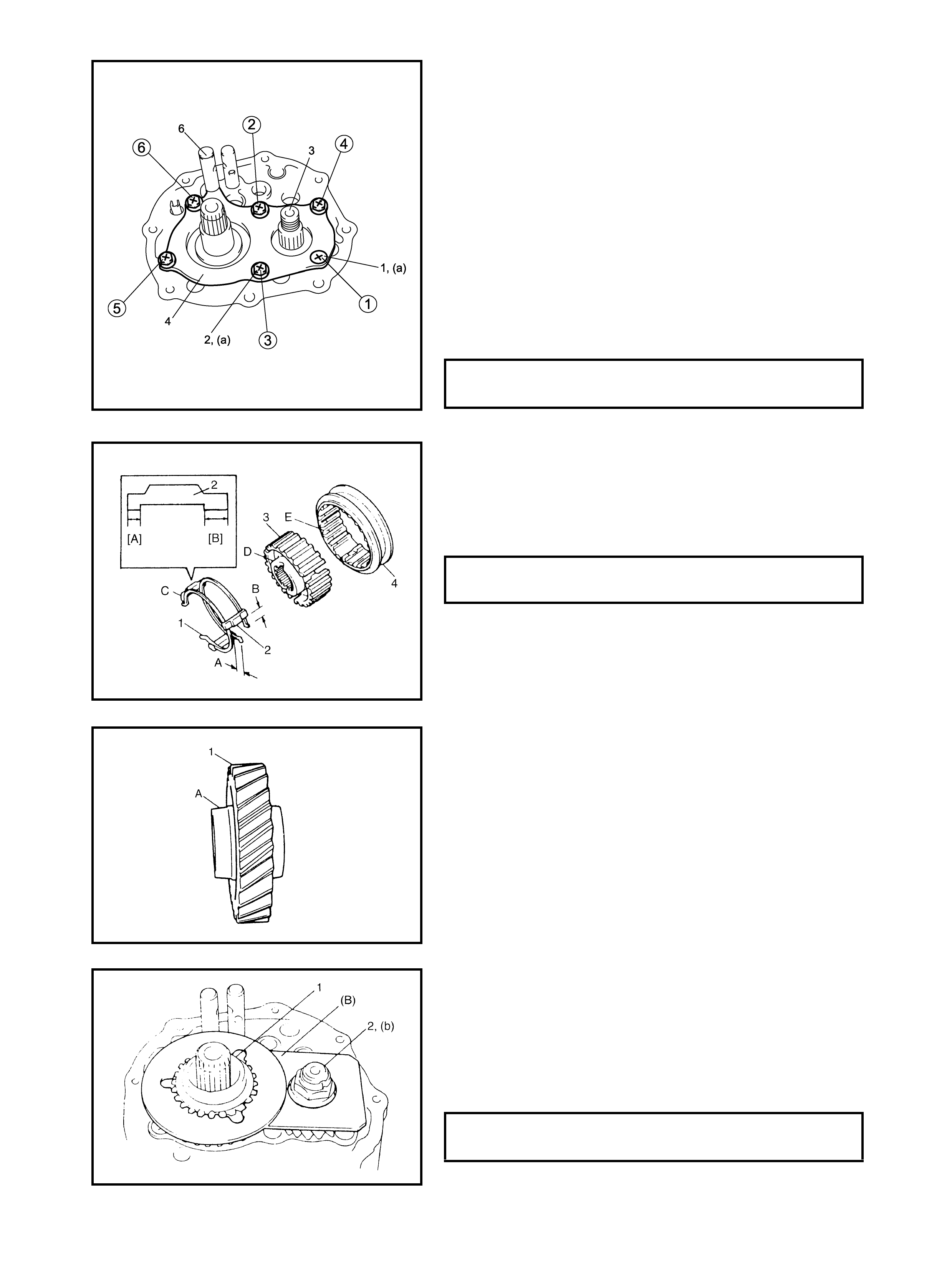
4.4 GEAR SHIFTER COMPONENT IDENTIFICATION
Legend
1. Gear shift & se lect shaft 15. Gear s hift interlock bolt
: Apply sealant Three Bond No. 12 15 to bolt
2. 5t h & reverse gear shift cam
3. Gear shift interloc k plate t hread.
4. Gear shift & select lever 16. Reverse gear shift lever bolt
5. S hift cable lever : Apply thread lock 1322 to all around
6. Select cable le v er thread part of bolt
7. Low speed gear shift shaft 17. Guide case
8. High speed gear shift shaft 18. Select le v er shaft bush
9. 5t h & reverse gear shift shaft : Apply Lithium grease to whole area of
10. 5t h & reverse gear shift shaft bush
11. 5th & re v erse gear shift guide shaft 19. Select le ver boss
12. Re verse gear shift arm : Apply Lithium grease to internal and
13. 5t h gear shift fork external diameter
14. 5t h to reverse interlock guide bolt
: Apply sealant Three bond 1215
to bolt th r e a d
Tightening torque
Do not reuse
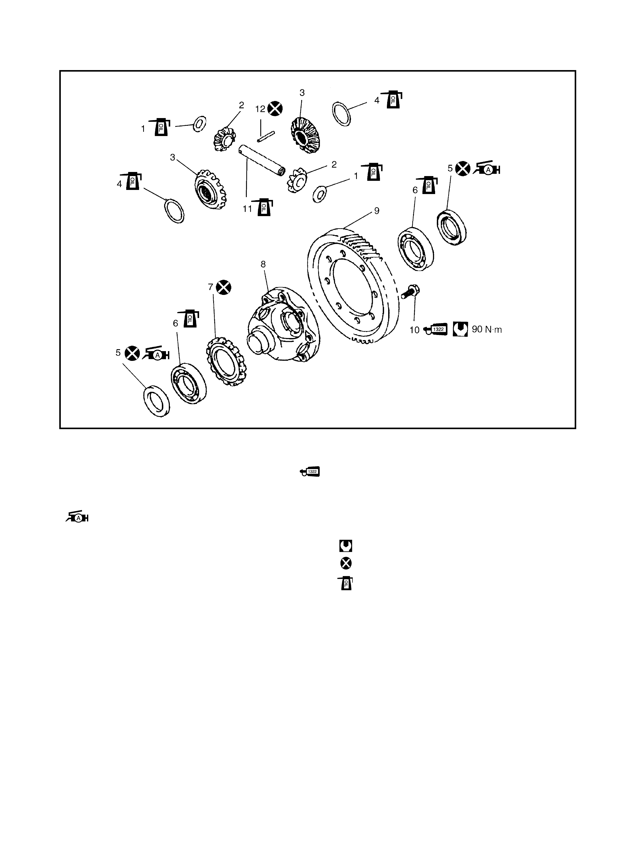
4.5 DIFFERENTIAL COMPONENT IDENTIFICATION
Legend
1. S ide gea r washer 9. Final gear
2. Differential side pinion gear 10. Final gear bolt
: Apply thread lo ck 1322 all around
thread part of bolt
3. Differential side g ear
4. S ide gea r washer
5. Differential side o il seal
: Apply Lithium grease to oil
seal lip
11. Differential pinion shaft
12. Differential pinion shaft pin
Tightening torque
6. Differential side b eari ng Do not reuse
7. Speed sensor ring Apply transaxle oil
8. Differential case
4.6 TRANSAXLE UNIT
REMOVAL
Under Hood
1. Disconnect the negative cable at the battery.
2. Undo the wiring harness clamps.
3. Disconnect the backup light switch connector, the VSS
connector and the ground transaxle cable.
4. Disconnect the clutch cable from the clutch release
lever and the bracket.
5. Disconnect the gear shift and the select control cables.
6. Remove the water pipe bracket bolts from the tran-
saxle.
7. Remove the transaxle bolts (1).
8. Remove the starter motor.
9. Support the engine by using a lifting device.
On Lift
10. Drain the transaxle oil, refer to 3.1 OIL CHANGE.
11. Drain the transfer oil, refer to Section 7D, 3.1 OIL
CHANGE.
12. Remove the left and the right drive shafts, refer to
Section 4A, 3.1 DRIVE SHAFT ASSEMBLY.
13. Remove the left side of the engine under cover, refer to
Section 6A1, 4.1 ENGINE ASSEMBLY.
14. Remove the clutch housing lower plate, refer to Section
7C, 4.1 CLUTCH COVER, CLUTCH DISC AND
FLYWHEEL.
15. Remove the transfer, refer to Section 7D,
4.1 TRANSFER UNIT.
16. Remove the transaxle to the engine bolt and nut.
17. Lower the vehicle and support the transaxle with a
transaxle jack.
18. Remove the engine left mounting (1) with the bracket
(2).
19. Remove the other attached parts from the transaxle.
20. Move the transaxle out to disconnect the input shaft
from the clutch disc then lower it.
INSTALLATION
CAUTION:
• Care should be taken not to scratch the oil seal lip
with the drive shaft while raising the transaxle.
• Do not hit the drive shaft joint with a hammer when
installing it into the differential gear.
Install the transaxle in the reverse order of removal proce-
dure noting the following:
• For installing the transfer, refer to Section 7D,
4.6 TRANSFER UNIT.
• For the fastener specified torque, refer to
4.1 TRANSAXLE UNIT COMPONENT
IDENTIFICATION in this Section.
•Push in the right and left hand drive shaft joints fully, so
as to engag e the snap rin g on th e shaft with th e differ-
ential gear .
•Fit the wiring harness securely in clamps.
•After connect ing the clutch cable, be sure to adjust the
play correctly, refer to Section 7C, 3.1 CLUTCH
CABLE.
•Fill the transaxle a nd the transfer with oil as specified,
refer to 3.1 OIL CHANGE in this Section.
•Connect the battery and check the function of the
engine, clutch and the transaxle.
4.7 UNIT DISASSEMBLY
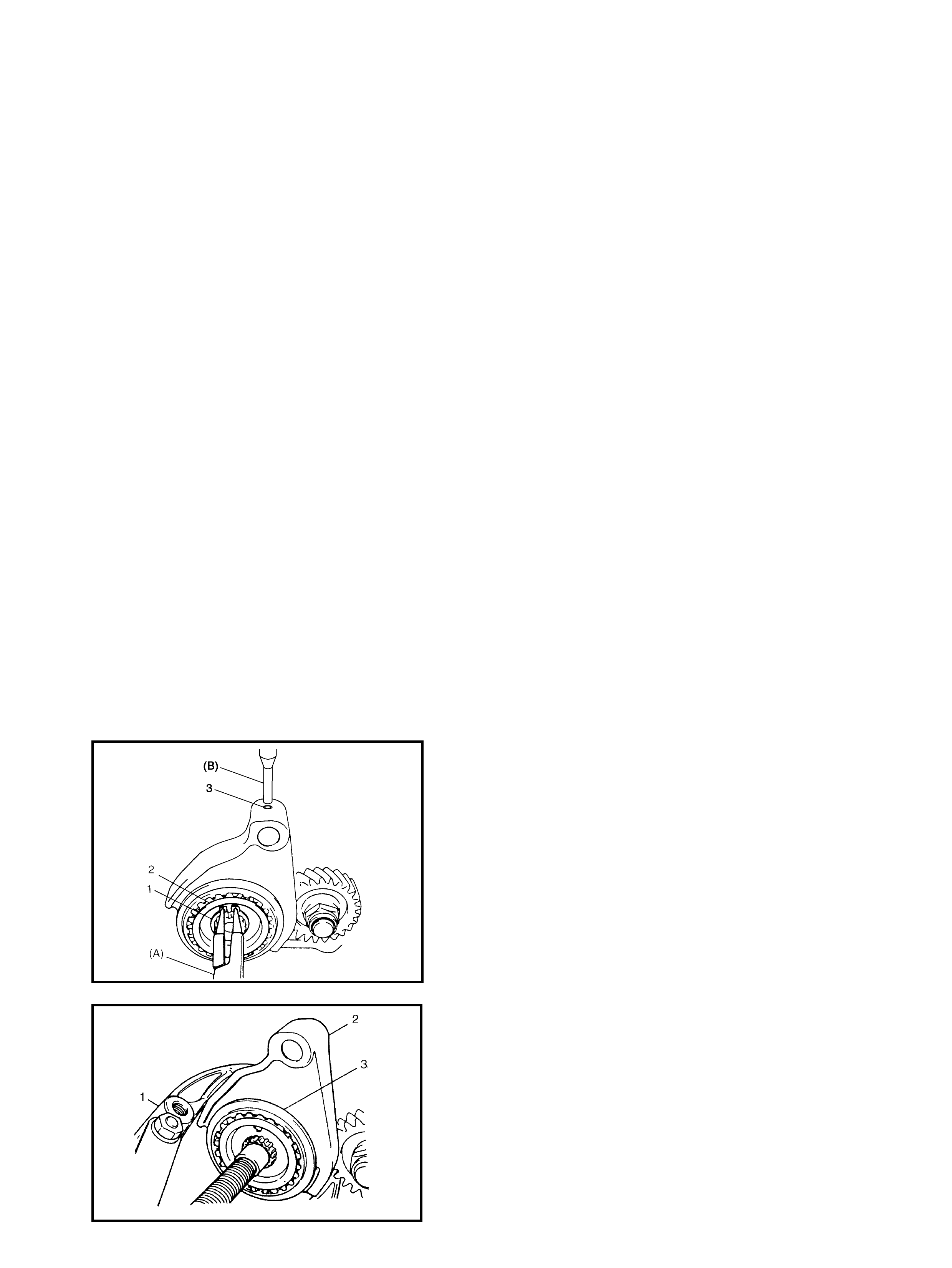
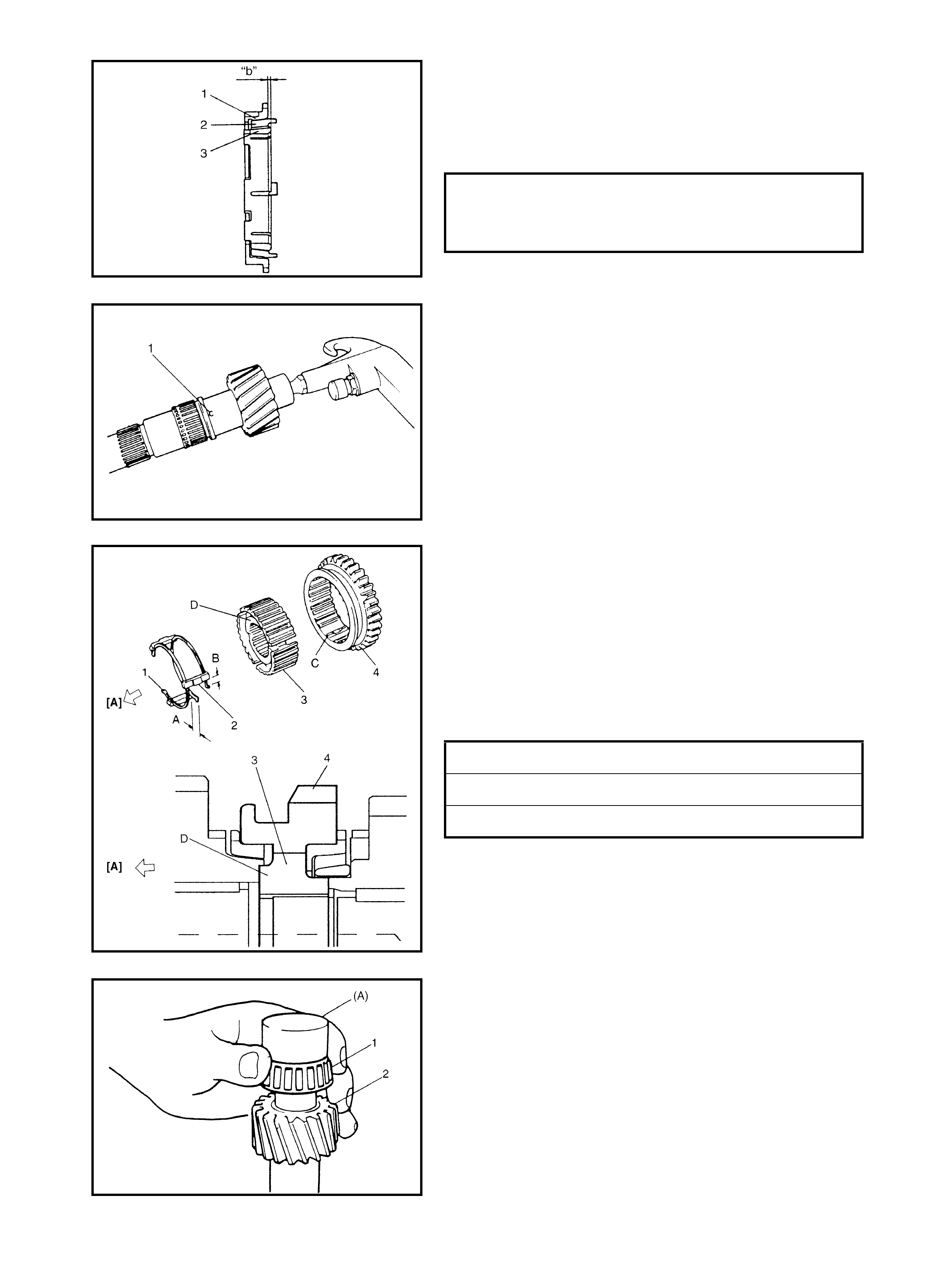
FIFTH GEARS
1. Remove the side cover bolts and take off the trans axle
side cov e r.
CAUTION: Care should be taken not to distort the side
cover when removing from the left case.
2. Using s pecial too l 09900-06107 (A), remove the circlip
(1) and then the hub plate (2).
3. Using special tool 09922-85811 (B), drive out the 5th
gear shift fork spring pin (3).
4. Remove the gear shift fork (2), sleeve and hub
assembly (3), synchroniser ring spring, synchroniser
r ing and the 5th gear together. Use a gear puller (1) for
removal if the spline fitting of the hub is tight.
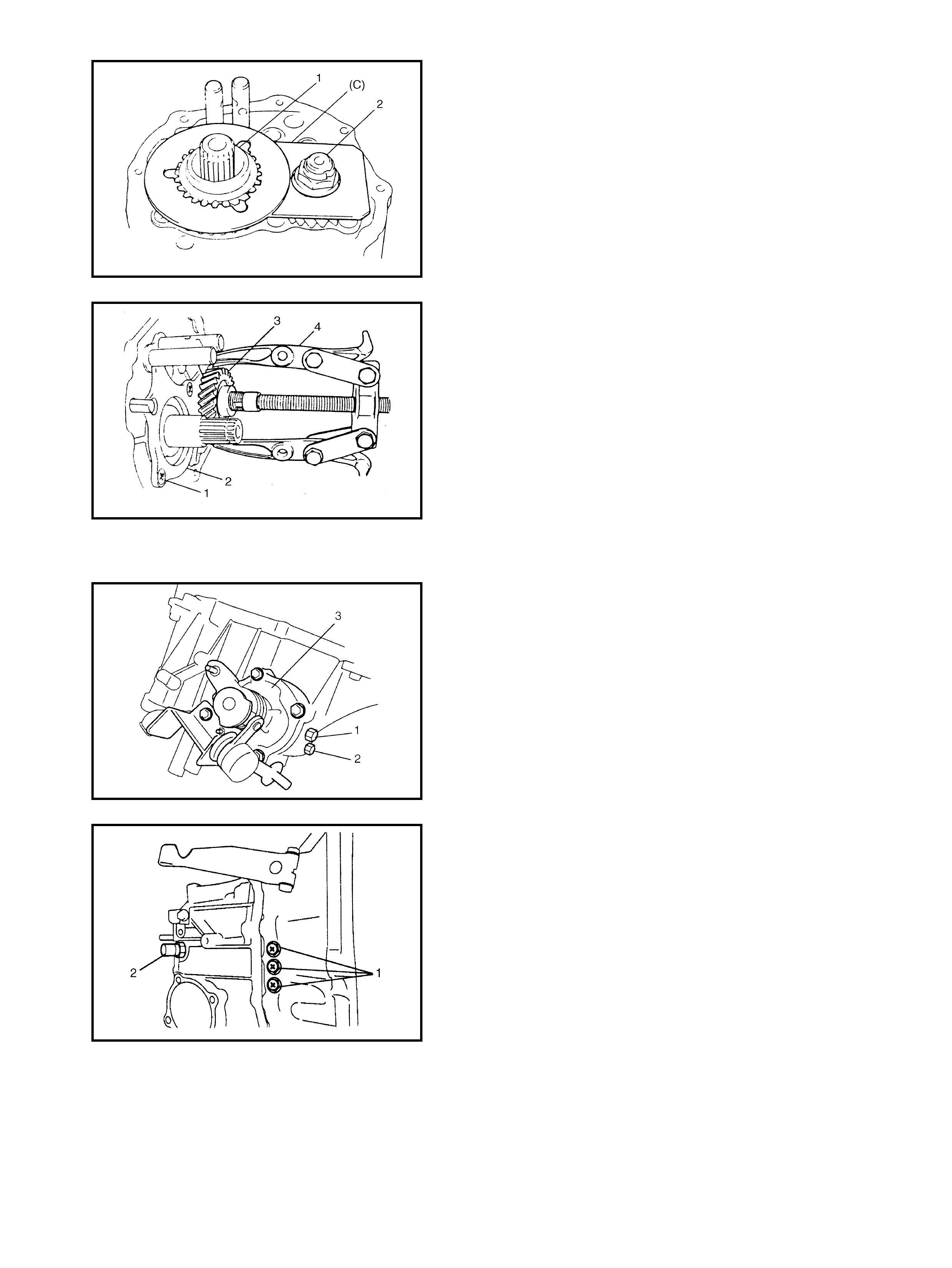
5. Unstake the countershaft nut.
6. Install the input shaft 5th gear (1) and special tool
09927-76010 (C) t o stop the rotation of the shaf ts, and
then remove the countershaf t nut (2).
7. Remove the special tool, the input shaft 5th gear, the
needle bearing of the separated steel cage type and
then the count er shaft 5t h gear. A gear puller (4) would
be necessary if the s pline fitting of the counter shaft 5th
gear (3) is tight.
8. Remove the plate screws (1), take off the left case
plate (2), and the bearing set shim.
GEAR SHIFTER, INPUT SHAFT AND COUNTER
SHAFT
1. Remove the gear shift interlock bolt (1) and the 5th
reverse interlock guide bolt (2) from the transaxle case.
2. Remov e the gear shifter assemb ly (3).
3. Remove the gear shift locating bolts (1) with the
washers, then take out the locating springs and the
steel balls.
4. Remov e the back up light switc h (2).
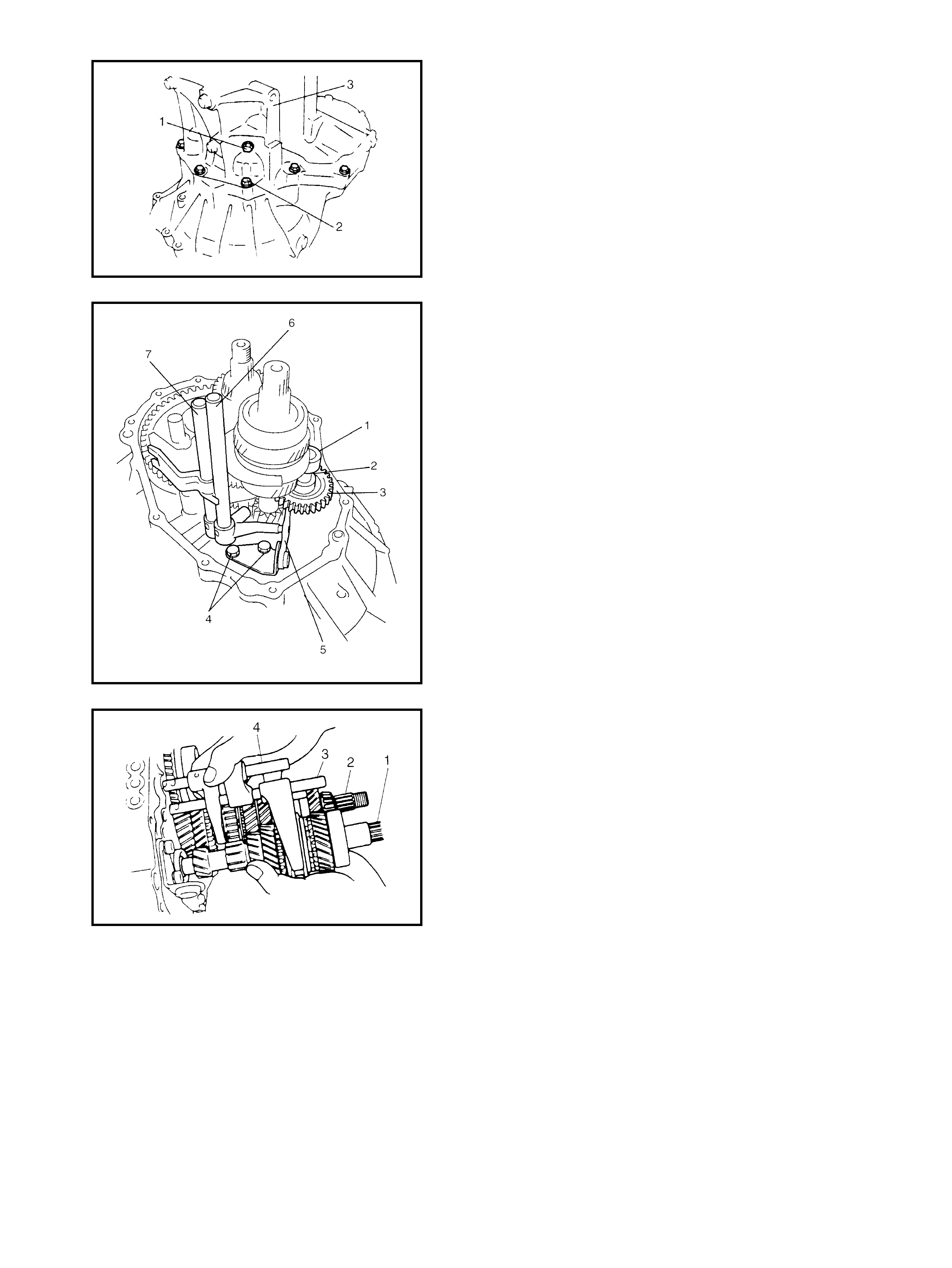
5. Remove the reverse shaft bolt (1) with the washe r.
6. Remove the case bolts (2) from outside and another
bolt from the clutch housing side.
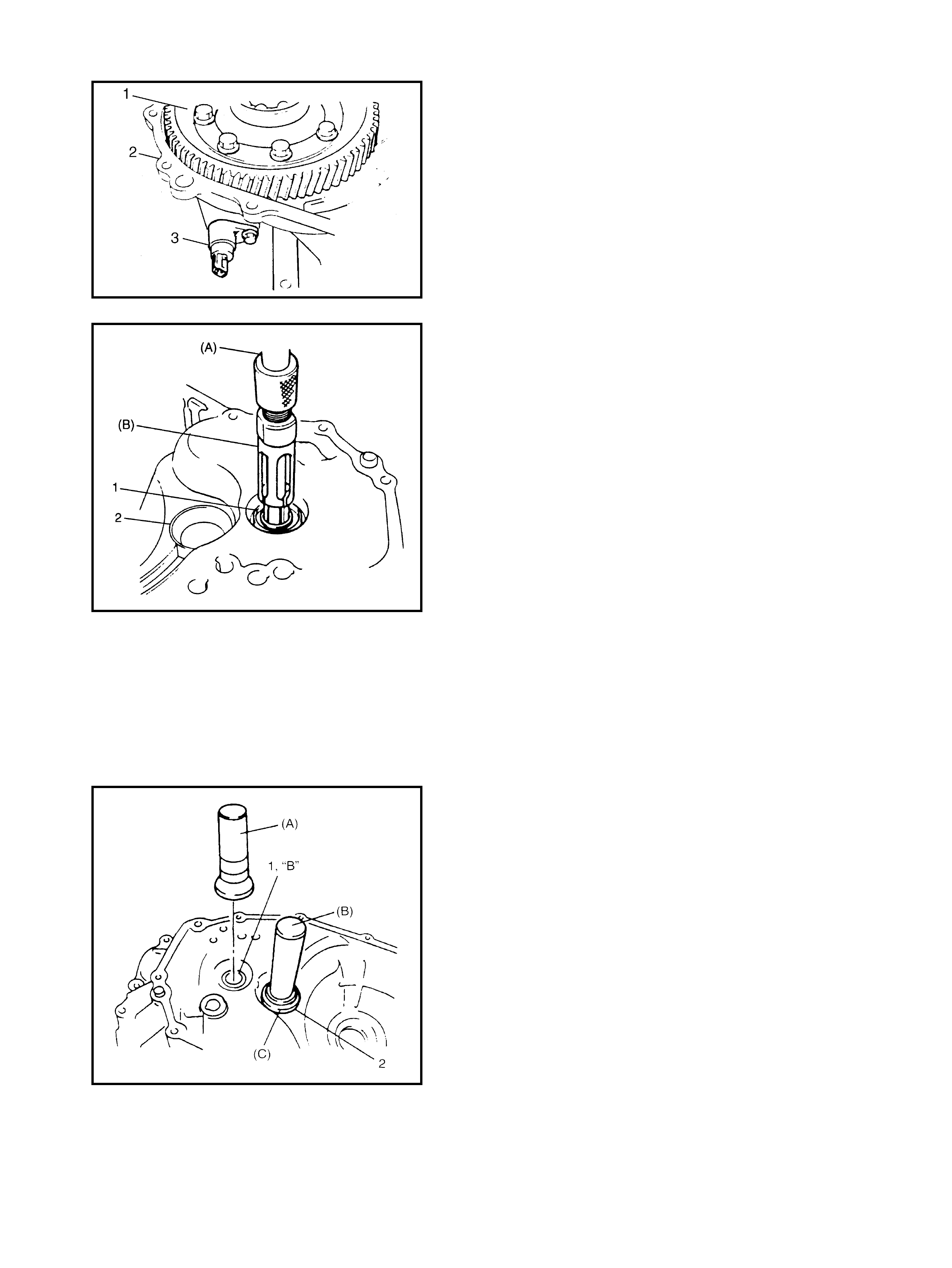
7. Remove t he left case (3) by tapping the flanges with a
plastic hammer.
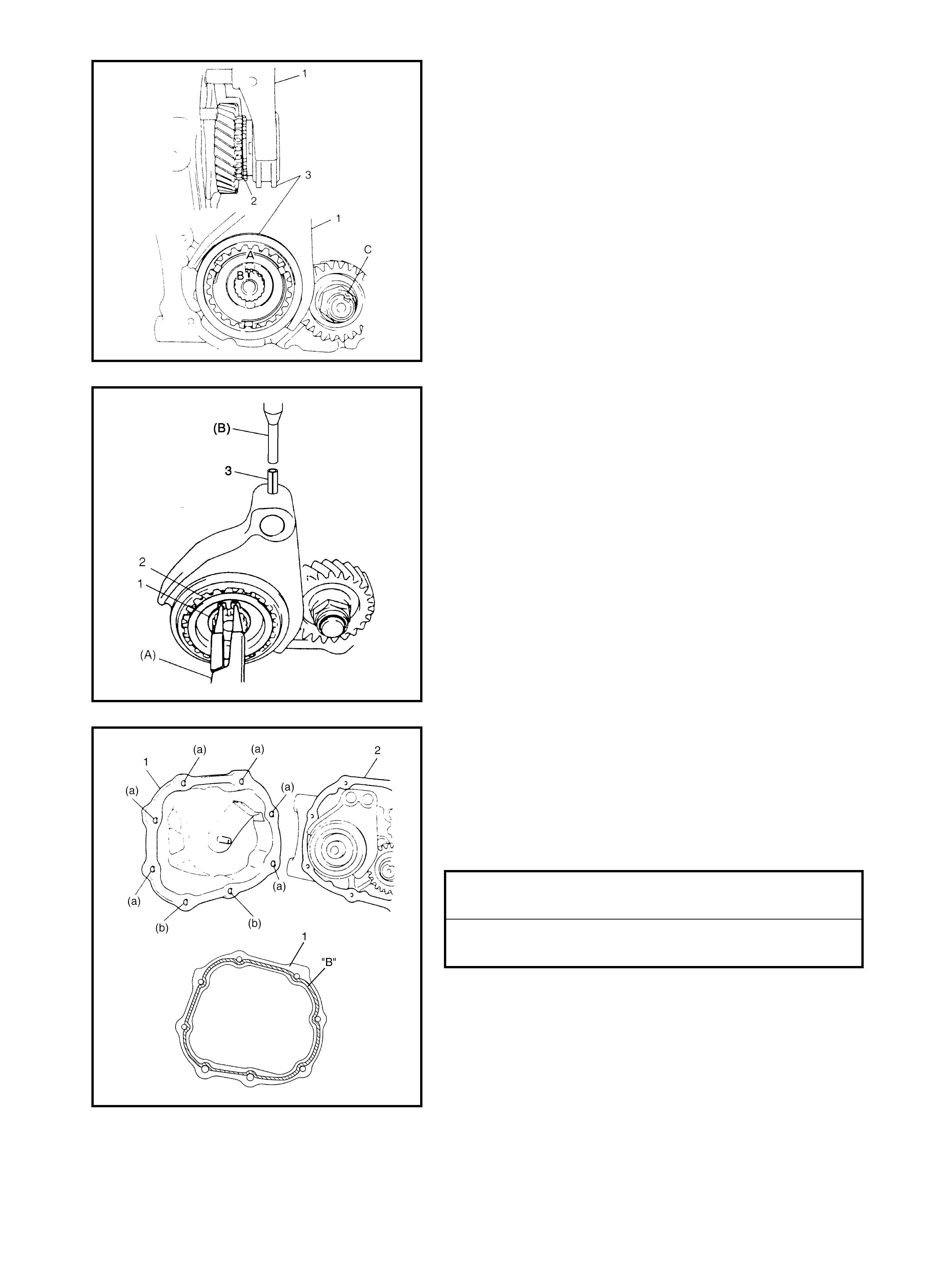
8. Remove the reverse gear shaft (1) with the washer (2),
take off the reverse idler gear (3).
9. Remove the reverse gear shift lever bolts (4), and the
re verse gear shift lever (5).
10. Remove the 5th and reverse gear shift guide shaft (6)
together with the 5th and rev erse gear shift shaft (7).
11. Tap the input shaft end with a plastic hammer and
part ially push out as an assembly from the case.
12. Remove the input shaft assembly (1), the counter shaft
assembly (2), the high speed gear shift shaft (3) and
the low speed gear shift shaft (4) as one unit.
13. Remove the count er shaf t left beari ng c up from the l eft
case.
14. Remove the differential side left oil seal also from the
left case .
RIGHT CASE
1. Remove the differential gear assembly (1) from the
right case (2).
2. Remov e the bolt and then pull out the VSS (3).
3. Remove the input shaft right bearing, if fitted in the
r ight case and remove the input shaft oil seal (1) using
specia l tools 09930-30104 (A) and 09923-74510 (B ).
4. Remove the countershaft right bearing cup (2) using
specia l tools 09941-64511 and 09923-30104.
4.8 SUB ASSEMBLY SERVICE
NOTE: B efore instal lation, was h ea ch part and ap pl y the
sp ecified ge ar oil to th e slidi ng faces of the b earin g and
the gear.
RIGHT CASE
1. Install the input shaft oil seal (1) facing its spring side
upward. Use special tool 09951-76010 (A) and a
hammer f or installation and apply grease “B” to oil seal
lip.
“B”: Lithium grease
2. Install the countershaft right bearing cup (2) by using
specia l tools 09924-74510 (B ), 099 25- 68 210 (C) and
a hamm er.
LEFT CASE
1. If the input oil gutter has been removed, install it with
the bolt to which thread lock cement “A” has been
applied.
“A”: Thread lock cement 1322
2. Install the differential side left oil seal (1) by using
special tool 09913-75510 (A) with a hammer . F ace the
spring side inward and insert, until it becomes flush
with the case surface.
3. Appl y grease “B” to the oil seal.
4. Install the counter shaft left bearing cup into the case
bore, by lightly ta pping it with a plastic hammer.
“B”: Lithium grease
INPUT SHAFT ASSEMBLY
Disassembly
1. Remove the input shaft right be aring (2) from the input
shaft (1) by using a bearing puller (3) and a press.
2. Drive out the 5th gear spacer (2), left bearing (3) and
the 4th gear (4) together from the input shaft (1) u sing
a puller (5) and a press.
CAUTION: To avoid the gear tooth from being dam-
aged, support the flat side of the bearing puller.
3. Take out the 4th gear needle bearing and the high
speed synchroniser ring.
OIL GUTTER BOLT (a)
TORQUE SPECIFICATION 10.0 Nm
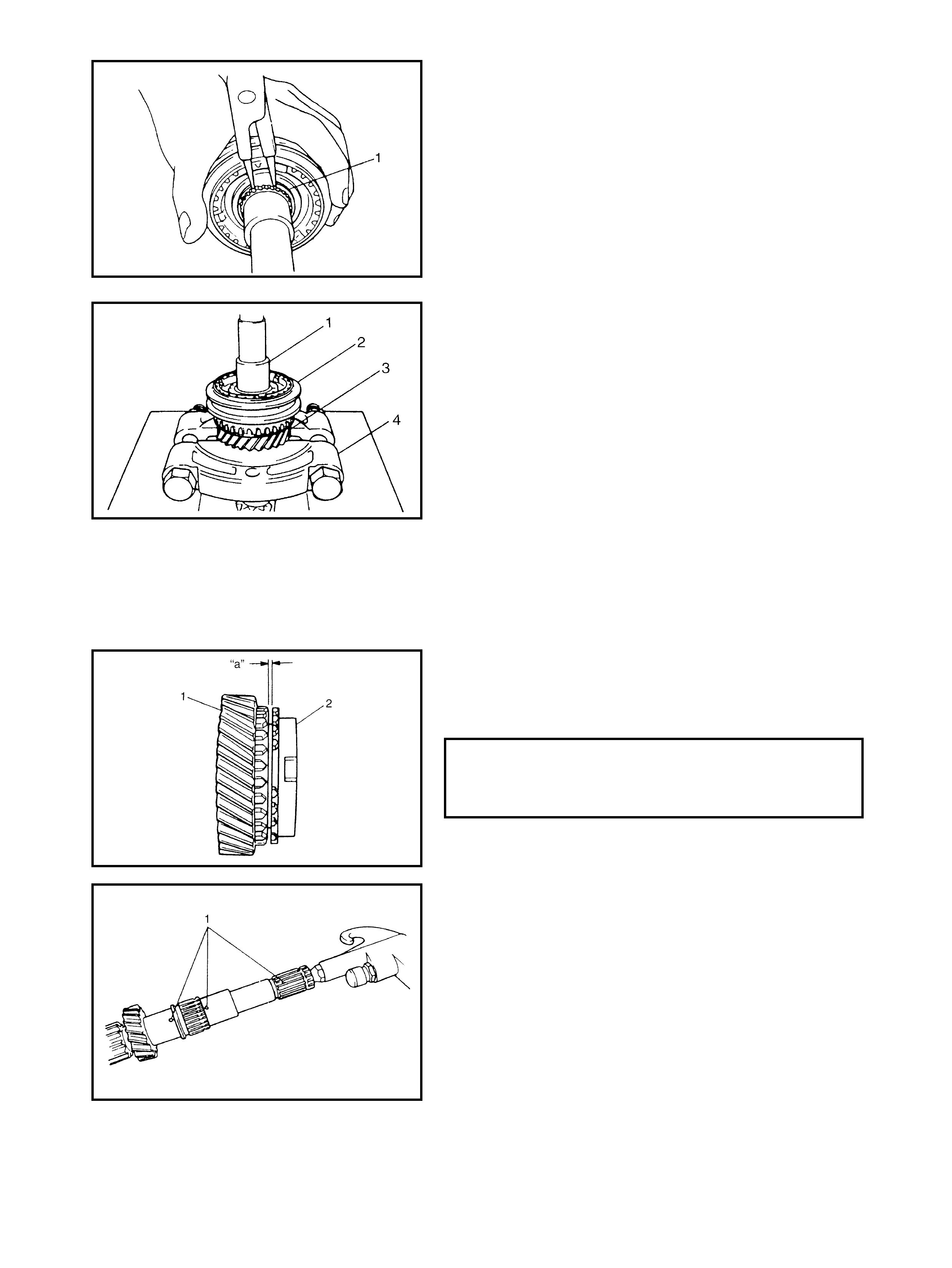
4. Using circli p pliers, remo ve the circlip (1).
5. Using a puller (4) and a press, drive out the high speed
synchroniser sleeve and the hub assembly (2) together
with the 3rd gear (3), from the input shaft (1).
CAUTION: Make sure to use the flat side of the puller
to avoid causing damage to the 3rd gear tooth.
6. Take out the 3rd gear needle bearing from the shaft.
7. Disassemble the synchroniser sleeve and the hub
assembly.
Inspection and Reassembly
1. Clean a ll the components thoroughly, inspect them for
any abnormality and replace if necessary.
2. If the synchroniser needs to be repaired, check
clearance “a” between the ring (2) and the gear (1).
3. Check each chamfered tooth of the gear, the ring and
the sleeve to determin e the parts to replace.
4. To ensure lubrication, air blow oil holes (1) and make
sure that they are free from any obstruction.
SYNCHRONISER RING AND GEAR
CLEARANCE STANDARD “a”:
SERVICE LIMIT “a”:1. 0 - 1. 4 mm
0.5 mm

5. Fit the high speed synchroniser sleeve (4) to the hub
(3), insert the 3 keys (2) and then the set springs (1).
NOTE:
•No specific direction is assigned to each key, but it is
assigned as the sleeve & hub assembly.
•The size of the high speed synchroniser sleeve, hub,
keys and springs, is between those of the low speed
and the 5th speed ones.
•Synchroniser key installation position: A = B
6. Driv e in the right bearing (1), to the input shaft (2) using
special tool 09913-80113 (A) and a hammer.
7. Install the 3rd gear needle bearing of the resin cage
type, apply oil, then install the 3rd gear (1) and the syn-
chroniser ring (2).
8. Drive in the high speed sleeve and the hub assembly
(3) by using special tool 09913-84510 (C) and a
hammer, facing the long flange side (B) of the hub
towards the 3rd gear [A].
NOTE:
•While press-fitting the sleeve and the hub, make sure
the synchroniser rin g key slots (A) are aligned with the
keys in the sleeve and the hub assembly.
•Check the free rotation of the 3rd gear after press-fit-
ting the sleeve and the hub assembly.
•Synchroniser rings for 3rd and 4th are identical.
[A]: 3RD GEAR SIDE
C: LONG F LAN GE
D: KEY WAY
E: PROJECT END
9. Install the circlip (1) confirming that the circlip is
installed in the groove securely.
10. Install the needle bearing (2) of the steel cage type,
and apply oil.
11. Install the synchroniser ring (3) and the 4th gear (4 ).
12. Press-fit the left bearing (2) using the special tool
09925-9822 1 (C) and a ham me r.
13. Using the same special tool, drive in the 5th gear
spacer (1).
CAUTION: To prevent the 5th gear spacer from being
distorted because of excessive compression, do not
press-fit together with the left bearing.
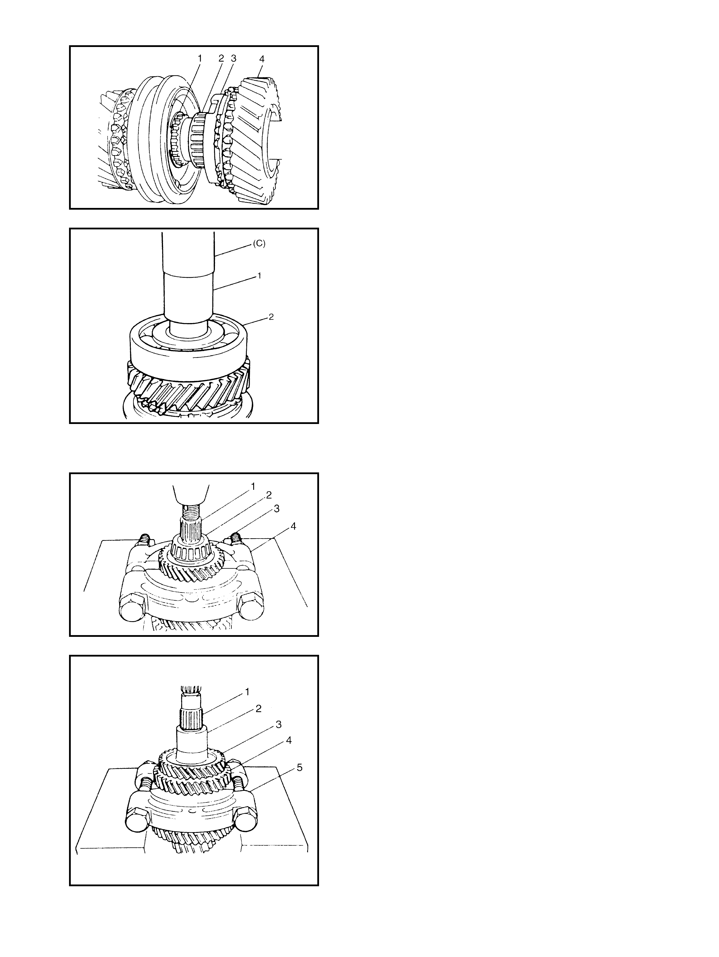
COUNTER SHAFT ASSEMBLY
Disassembly
1. Drive out the left bea ring cone (2) with the 4t h ge ar (3)
from the counter shaft (1) using a puller (4) and a
press.
CAUTION:
•Use a puller and a press that will bear at least 5 ton
safely.
•To avoid tooth damage, support the 4th gear on the flat
side of the puller .
2. Apply the puller (5) to the 2nd gear (4).
3. Driv e out the 3rd & 4th gear spacer (2), the 3rd gear (3)
together with the 2nd gear from the counter shaft (1) by
using a press.
4. Remove the needle bearing of the separated steel
cage type from the counter shaft.
CAUTION:
•If the compression exceeds 5 ton, release the com-
pression once, reset the puller support and then
continue to press the work again.
•To avoid the gear tooth from being damaged, sup-
port the flat side of the bearing puller.
5. Remove the 2nd synchroniser outer ring, the centre
cone and the inner ring.
6. Using circli p pliers, remo ve the circlip (1).
7. Apply a puller (3) to the 1st gear (2).
8. Drive out the low speed synchroniser sleeve and the
hub assembly (1) with the gear using a press.
CAUTION: To avoid gear teeth from being damaged,
support the flat side of the bearing puller.
9. Disassemble the synchroniser sleeve and the hub
assembly.
10. Remove the needle bearing from the shaft.
11. Remove the right bearing cone (2) using a puller (3),
metal stick (1) and a press.
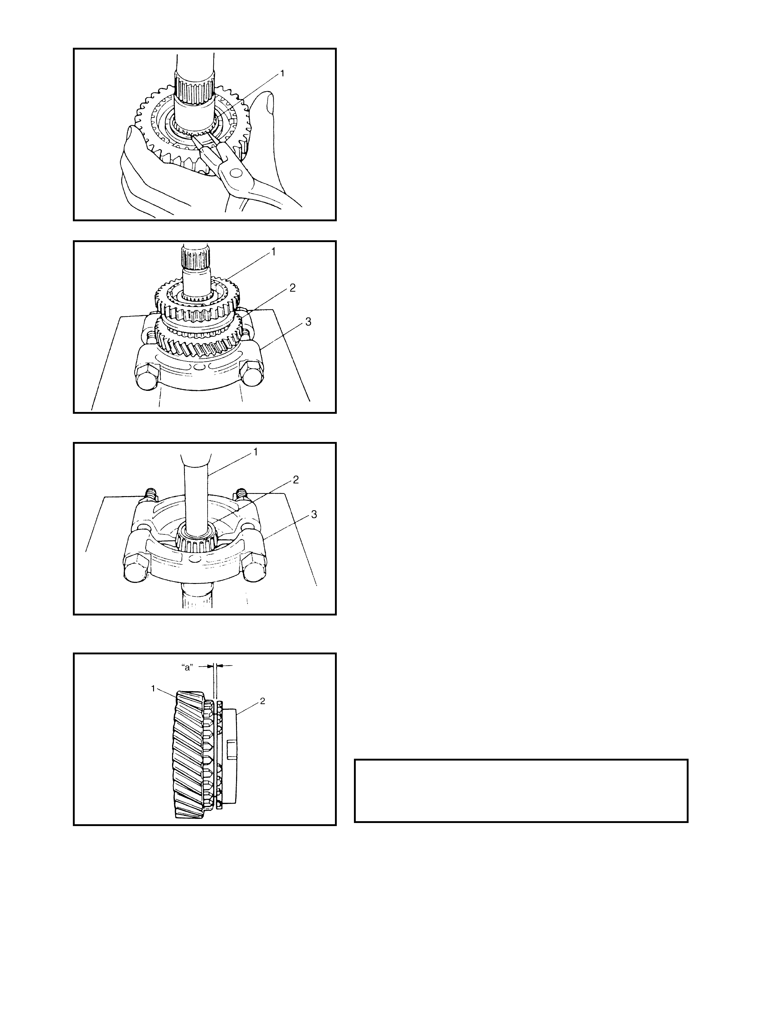
Inspection and reassembly
1. Clean a ll the components thoroughly, inspect them for
any abnormality and replace if necessary.
2. If the synchroniser needs to be repaired, check
clearance “a” between the ring (2) and the gear (1).
3. Check each chamfered tooth of the gear, the ring and
the sleeve to determin e the parts to replace.
SYNCHRONISER RING AND GEAR
CLEARANCE STANDARD “a”:
SERVICE LIMIT “a”:1. 0 - 1. 4 mm
0.5 mm
4. Assemble the synchroniser outer ring (1), the inner ring
(3) and the cone (2) together then measure the step
difference between the outer ring and the inner ring.
5. Check the gear teeth and the synchroniser ring and
replace if worn or damaged.
6. To ensure lubrication, blow air blow through the oil
holes (1) and make sure that they are free from any
obstruction.
7. Fit the low speed synchroniser sleeve (4) to the hub
(3), inser t 3 keys (2) and then the set springs (1).
NOTE:
•No specific direction is assigned to each key but it is
assigned as a slee ve and hub assembly.
•The size of the low speed synchroniser keys and
springs are larger, than those of the high speed and
the 5th speed synchroniser keys .
•Synchroniser key installation position: A = B
8. Install the right bearing cone (1) to the counter shaft (2)
using special tool 09923-78210 (A) and a hammer.
9. Install the needle bea ring of t he resin c age type. Apply
oil, then install the 1st gear and the 1st gear synchro-
niser ring.
SYNCHRONISER RING AND GEAR
CLEARANCE STANDARD “a”:
SERVICE LIMIT “a”:1. 0 - 1. 4 mm
0.5 mm
[A]: 1ST GEAR SIDE
C: KEY WAY
D: SHORT FLANGE
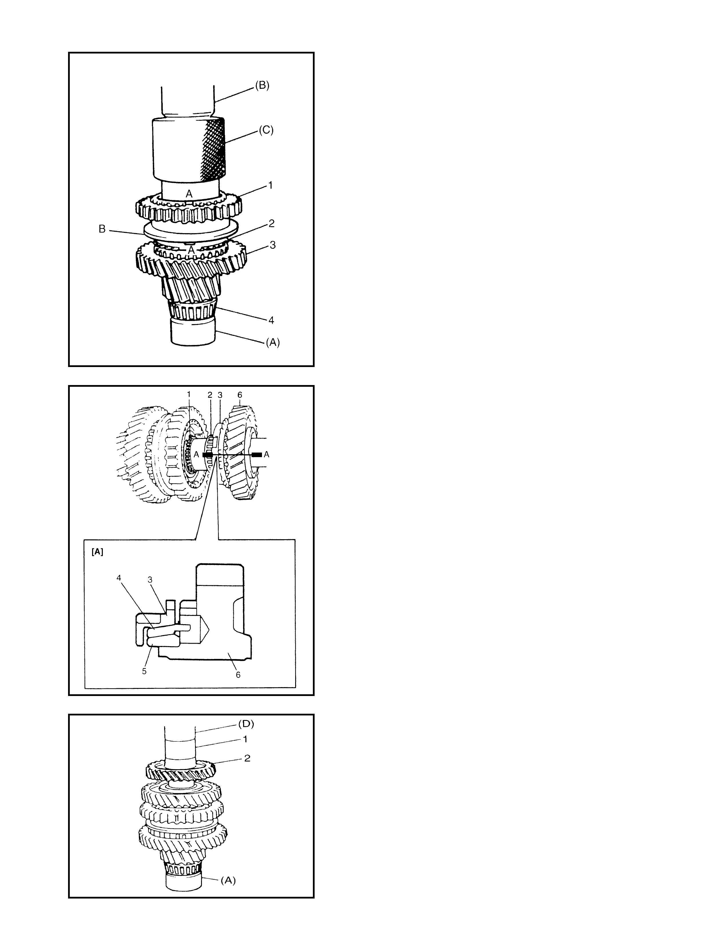
10. Driv e in the low speed sleev e and t he hub assembly (1)
by using special tools 09923-78210 (A), 09925-18011
(B), 09940-53111 (C) and a hammer. Face the “B”
side of the sleeve towards the 1st gear.
NOTE:
•Suppo rt the shaf t with the special tool, shown in figure,
so that the retainer of the bearing cone (4) will be free
from compression.
•Make sure that the synchroniser ring (2) and the key
slots are aligned with the keys while press-fitting the
sleeve and the hub assembly.
•Check free rotation of the 1st gear (3) after press-fitting
the sleeve and hub assembly.
•A: Align key slots with the keys.
11. Install the circlip (1) confirming that the circlip is
installed in the groove securely.
12. Install the needle bearing (2) of the separated steel
cage type and apply oil.
13. Assemble the synchroniser outer ring (3), the centre
cone (4) and the inner ring (5), and install to the 2nd
gear (6), refer [A]: Section A-A.
14. Press-fit the 3rd gear (2) and the spacer (1) by using
specia l tools 09923-78210 (A ), 099 13- 80 113 (D) and
a press.
CAUTION: Press-fit the 3rd gear and the spacer first,
and then the 4th gear separately so that the counter
shaft will not be compressed excessively.
15. Press-fit the 4th gear (2) using t he same procedure as
the above.
16. Install the left bearing cone (1) using special tools
09923-7821 0 (A), 099 25-982 21 (E) and a hammer.
NOTE: For the protection of the right bearing cone (3),
always support the shaft with special tools as shown in
the figure.
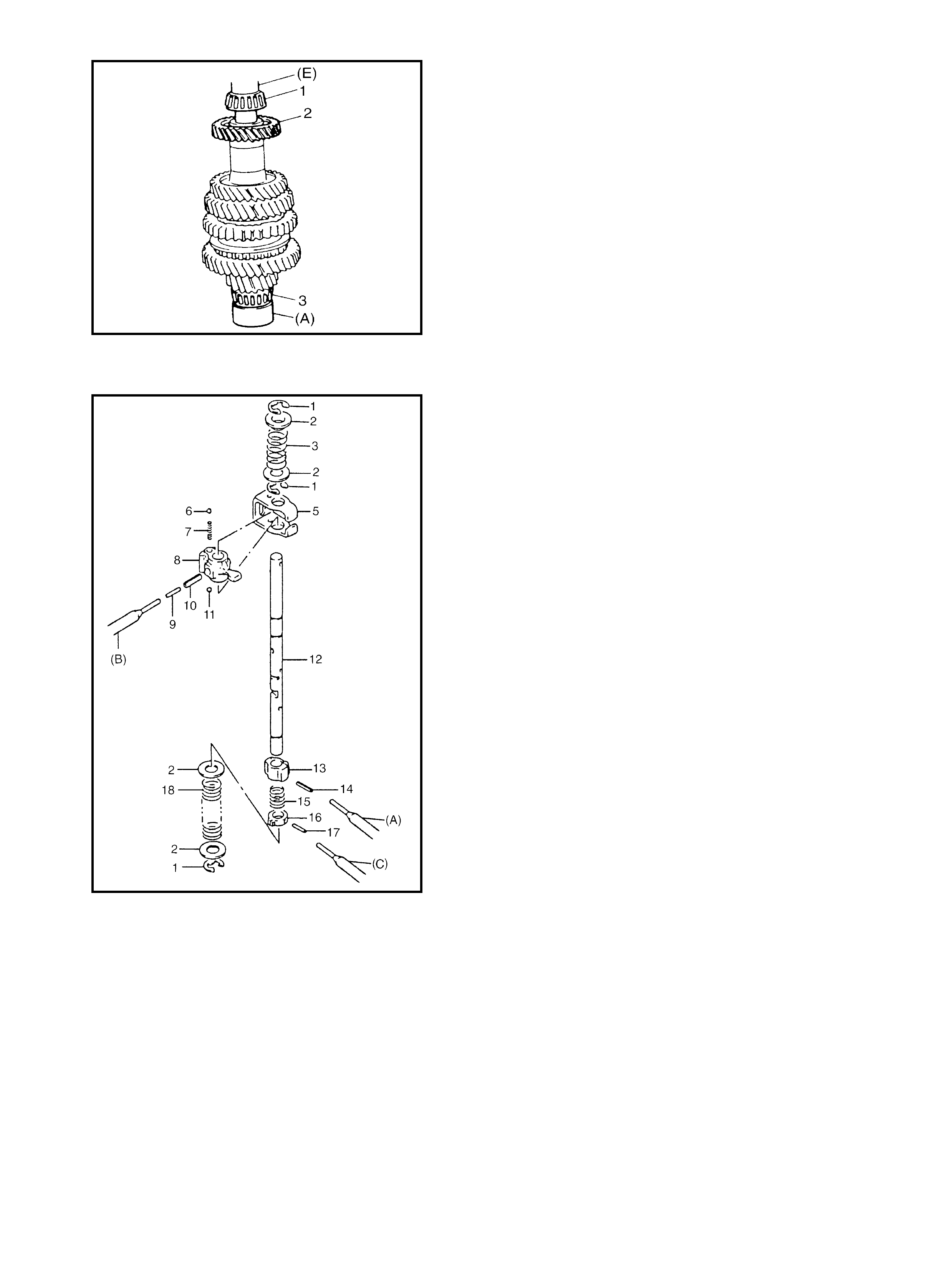
GEAR SHIFTER
Gear Shift and Select Shaft Assembly
1. Push the spring pins out using specified spring pin
removers 09922-85811 (A) 4.5 mm, 09925-78210
(B) 6.0 mm, Commercially available spring pin
remover (C) 2.8 - 3.0 mm.
2. Inspect component parts for wear, distortion or
damage. If required, replace any defective parts.
NOTE:
•When dr iving in t he spring pin s, prevent the shaft from
being bent by supporting it with a wood block.
•Assemble the 5th and the reverse gear shift cam with
the pit and the spring pin aligned.
•Make sure to select an appropriate spring by identify-
ing the painted c olours to keep the gear shifting perfor-
mance as designed.
•Low speed select spring - No paint
•Reverse select spring - Pink
Legend
1. E-ring 10. Spr ing pin
2. Washer 11. Ball
3. Reverse select spring 12. Gear shift & select shaft
4. Blank 13. 5th & rev erse gear shift cam
5. Gear sh ift inte rlo ck plate 14. Spr ing pin
6. Ball 15. C am guide retur n sprin g
7. Gear shift interlock spring 16. 5th & reverse gear shift cam guide
8. Gear sh ift & select lever 17. Spr ing pin
9. Spr ing pin 18. Low speed select spr ing
High Speed and Low Speed Gear Shift Shafts
Inspection
1. Using a feeler gauge, check the clearance between the
fork (1) and the sleeve (2) and replace those par ts if it
exceeds the limit below.
NOTE:
For correct judgement of parts replacement, carefully
inspec t the contact port ion of the fork and the sleeve.
2. Insert each gear shift shaft into the case and check
that it moves smoothly. If it doesn’t, correct using an
oilstone, reamer or the like.
5th & Reverse Gear Shifter
1. Disassemble component parts using special tool
09922-85811 (A) and a hammer.
2. Replace or c orrect the part s as requi red and as semble
the shafts makin g sure that the component parts are in
the correct order as shown in the fi gure.
NOTE:
•Distinguish the reverse gear shift ar m spring (Blue) (2)
from the low speed locating spri ng (Yellow).
•Install the 2 s teel b alls (3) in the reverse gear shi ft ar m
(1) without fail.
•Drive in the spring pin for the reverse shift ar m, facing
the slit (A) toward the front.
Legend
FORK AND SLEEVE CLEARANCE
SERVICE LIMIT “a”: 1.0 mm
1. 5th & rev erse gear shift yoke 5. Snap ring
2. Bal l 6. P in
3. 5th & rev erse gear shift guide shaft 7. Ball
4. Reverse gear sh ift arm 8. R everse gear shift ar m spring
DIFFERENTIAL ASSEMBLY
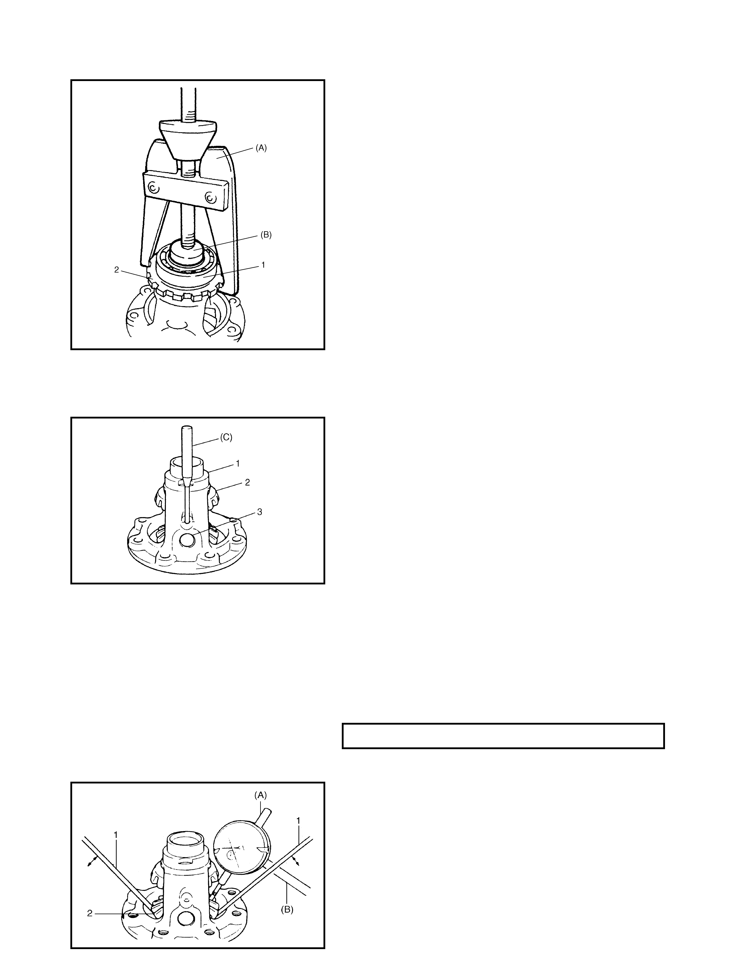
Disassembly
1. Using special tools 09913-60910 (A), 09925-88210
(B) remove the right bearing (1) and the sensor rotor
(2).
2. Remove the left bearing in the same manner.
3. Support the differential case (1) with a soft jawed vise
and remov e the final gear bolts.
4. Take out the final gear (2).
5. Drive out the differential pinion shaft (3) pin using
special tool 09922-85811 (C) and a hammer, then dis-
assembl e the component parts.
Adjustment and reassembly
Judging from any abnormalities noted before disassembly
and what is found through a visual i nspection of the compo-
nent parts after disassembly, prepare to replace the parts
and proceed to reassembly. Ensure that all parts are clean.
1. Assemble the differential gear and measure the thrust
play of the differential gear as follows.
Left side
•Hold the differential assembly with a soft jawed vise
and apply the measuring tip of the dial gauge 09900-
20607 (A) and stand 09900-20701 (B) to the top sur-
face of the gear.
•Using two screwdrivers (1), move the gear (2) up and
down and read the movement of the dial gauge pointer.
DIFFERENTIAL GEAR THRUST PLAY 0.03-0.31 mm
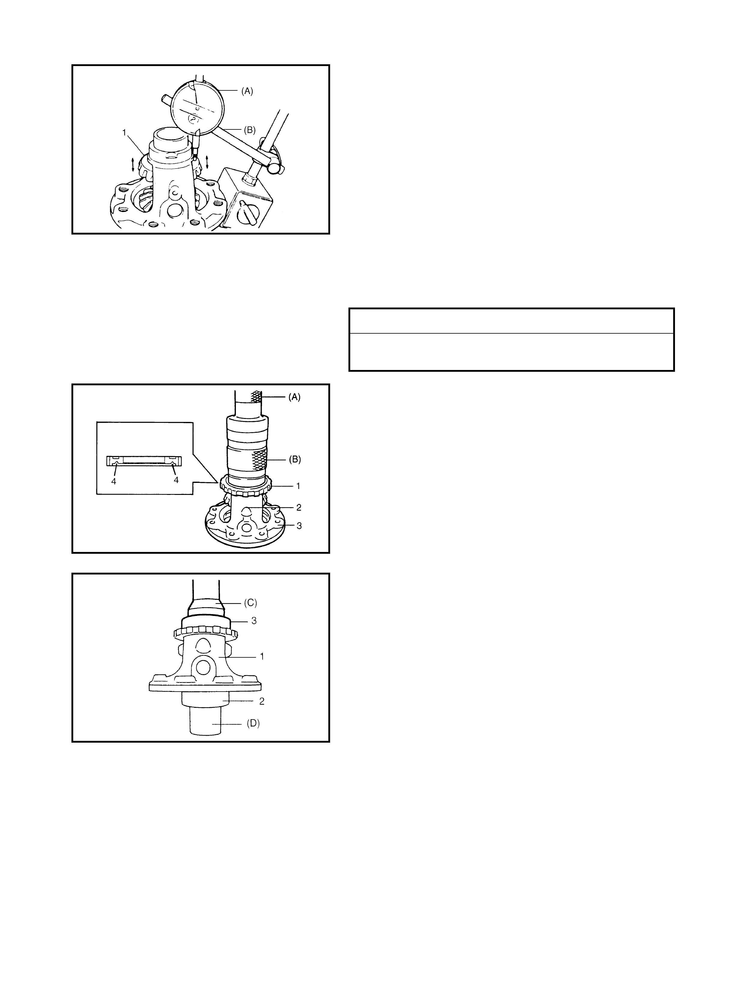
Right side
•As in the previous procedure, set the dial gauge tip
09900-20607 (A) and the stand 09900-20701 (B) to
the gear (1) shoulder.
•Move the gea r up and down by hand and read the di al
gauge.
2. If the thrust play is out of specification, select a suitable
thru st washer from the fo llowing available size.
3. Install the t hrust washer and rec heck that the spec ified
gear play is obtained.
4. Drive in a new differential pinion shaft pin (2) until the
depth from the differential case (3) surface, is about 1
mm.
5. Press-fit the new sensor rotor (1) with the groove (4)
side downward as shown, using special tools 09913-
75510 (A), 09940-54910 (B) and a copper hammer.
6. Press-fit the left bearing using special tools 09951-
76010 (C), 09951-16060 (D) and a co pper ham mer.
7. Support the differential assembly (1) as illustrated, so
the left bearing (2) is floating, then press-fit the right
bearin g (3) like the left bearing in Step 6.
THRUST WASHER THICKNESS
0.90 mm, 0.95 mm , 1. 00 mm, 1.05 mm , 1. 10 mm, 1.15 mm
1.20 mm .
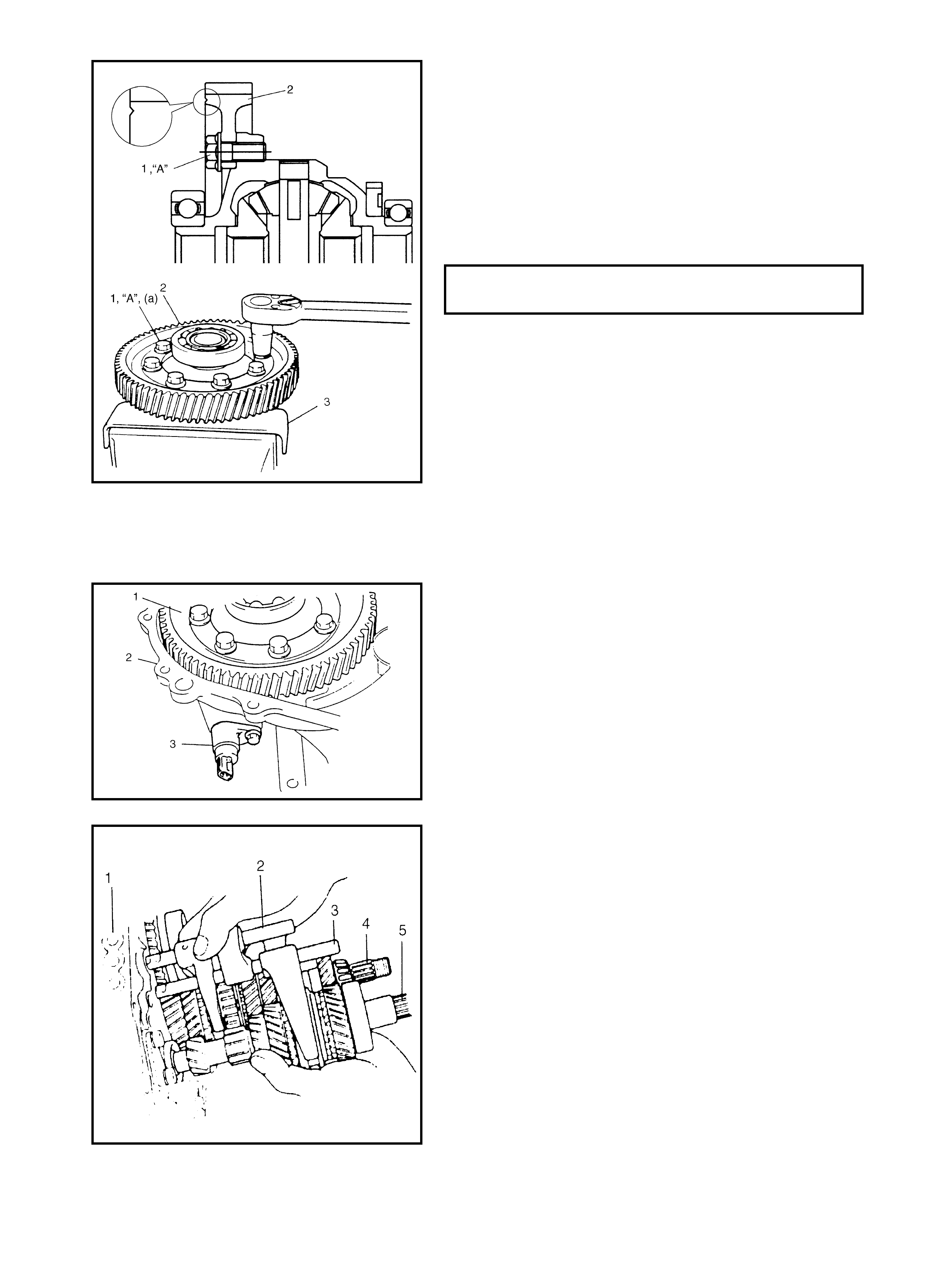
8. Hold the differential assembly with a soft jawed vise
(3), install the final gear (2) as shown in figure, then
tighten the bolts (1) with the thread lock cement “A”
applied to specified torque.
NOTE: Make sure to install the final gear in the correct
installing direction.
“A”: Lock thread cement 1322
CAUTION: Use of any bolts other than those speci-
fied is prohibited.
4.10 UNIT ASSEMBLY
DIFFERENTIAL TO LEFT CASE
Assembly
1. Install the differential assembly (1) into the right case
(2).
2. Insert t he VSS (3) with Lithiu m grease applied to its O-
r ing, then tighten it with bolt.
3. Assemble the input shaft (5), the countershaft (4), the
low speed gear s hift sha ft (2) and the high speed gear
shift shaft (3) together, then install them into the right
case (1).
CAUTION: Take care not to damage the oil seal lip
when installing the input shaft, or oil leakage may
take place.
NOTE:
•The input shaft right bearing on the shaft can be
installed into the right case by tapping the shaft with a
plastic hammer.
•Check to make sure that the counter shaft is engaged
with the final gear when installing.
FINAL GEAR BOLT (a)
TORQUE SPECIFICATION 90 Nm
4. Install the 5th and the reverse gear shift shaft (1) with
the 5th and reverse gear shift guide shaft (2) into the
r ight case (5). The reverse gear shift arm (4) has to be
joined with the reverse gear shift lever (3) at the same
time.
5. Install the reverse gear shift lever, fasten it with bolts
after applying thread lock cement “A”
“A”: Lock thread cement 1322.
NOTE: When installing the reverse gear s hift lever, set it
as the following specification.
NOTE:
•Distance (b) can be measured by provisionally install-
ing the reverse gear shaft.
•When (b) is 5 mm, clearance between the reverse idler
gear groove and the shift lev er end will be 1 mm.
6. Make the reverse idler gear (1) with the reverse gear
shift lever (2), inser t the reverse gear shaf t (3) i nto the
case through the idler gear and then align the “A” in the
sh a ft w i t h th e “B” in the case.
NOTE:
•Make sure that the washer (4) has been installed in the
shaft above the gear.
•Check to confirm the reverse gear shift lever end has
clearance 1 mm (0.04 in.) to th e idler g ear groove.
7. Clean the mating surfaces of both the right case (2)
and the left case (1).
8. Using a 1.5mm in diameter bead of sealant “B” apply to
the right case and attach to the lef t case .
“B”: Sealant - Three Bond No. 1215
9. Tighten t he cas e bol ts (3) from the le ft case s ide to the
specified torque.
10. Install the reverse shaft bolt (4), to which thread lock
cement “A” have been applied with aluminum washer
and tighten it.
“A”: Thread lock cement 1322
11. Install another case bolts from the clutch housing side
and tighten them to specification.
REVERSE GEAR SHIFT LEVER BOLT (a)
TO RQUE SPECIF ICATION 23 Nm
DISTANCE BETWEEN LEVER END &
SHAFT BORE (b) 5 mm
TRANSAXLE CASE BOLT (b)
TORQUE SPECIFICATION 19 Nm
REVERSE SHAFT BOLT (c)
TORQUE SPECIFICATION 23 Nm
12. Che ck the locating spr ing for deterioration and rep lace
with a new one as necessar y.
13. Install the steel ball (4) and the locating spring for the
respective gear shift shaft. Fit the washer (2) and
tighten the bolt (1) to which sealant has to be applied to
its thread part
Sealant - Three Bond No. 1215.
FIFTH GEARS
1. To seat the countershaft left bearing cup (1) to the
bearing cone, tap the cup using special tool 09913-
84510 (A) and a plastic hammer.
2. Provisionally place a shim (2) on the bearing cup (3),
place a straight edge (1) over it and compress it by
hand throu gh the straight edge, and then mea sure “a”.
(Clearance between the case surface (4) and the
straight edge) by using a feeler gauge (5).
3. By repeating the above step, select a suitable shim
which adjusts the clearance “a” to the specification and
place on the bearing cup.
NOTE: Insert a 0.15 mm feeler gauge, to know whether
or not a shim fulfills the specification quickly.
LOCATING SPRING FREE LENGTH
LO W SPEED (3) AND
5th & REVERSE (6) STANDARD
SERVICE LIMIT 26.1 mm
25.0 mm
HIGH SPEED (5) STANDARD
SERVICE LIMIT 40.1 mm
39.0 mm
LOCATING SPRING BOLT (d)
TORQUE SPECIFICATION 13.0 Nm
CLEARANCE BETWEEN CASE SUR-
FACE & STRAIGHT EDGE (SHIM PRO-
TRUSION) “a”0.13 - 0.17 m m
AVAILABLE SHIM THICKNESS
0.40 mm, 0.45 mm , 0. 50 mm, 0.55 mm , 0. 60 mm, 0.65 mm
0.70 mm, 0.75 mm, 0.80 mm, 0.85 mm, 0.90 mm, 0.95 mm,
1.00 mm , 1.05 mm, 1.10 mm, 1.15 mm.
4. Inserting the end of the left case plate (4) in the groove
of the shift gui de shaft (6). Tighten with a new s crew (1)
and bolts (2) with adhesive, pre-coated temporarily
with less than specified torque.
CAUTION: Do not reuse the left plate screw and bolts.
Be sure to use new screws and bolts with adhesive
pre-coated. Otherwise, screw may loosen.
5. Finally, tighten the new screw and the bolts to the
specified torque in the order of the circled numbers
shown in figure.
NOTE: After tightening the screw, and the bolts, make
sure that the countershaft (3) can be rotated by hand
feeling some load.
6. Assemble the 5th speed synchroniser sleeve (4) and
the hub (3) with the keys (2) and the springs (1).
NOTE: The short side (C) [A] in the keys, the long flange
(D) in the hub and the chamfered spline (E) in the sleeve
should face inward (5th gear side).
7. Install the 5th gear (1) to the counter shaft, facing the
machined boss (A) inward.
8. Install the needle bearing of the separated steel cage
type to the input shaft, apply oil then install the 5th gear
(1) and special tool 09927-76010 (B) to stop the shaft
rotation.
9. Install the new countershaft nut (2) and tighten to the
specification.
LEFT CASE PLATE SCREW & BOLT (a)
TORQUE SPECIFICATION 11.0 Nm
SYNCHRONISER KEY INSTALLATION
POSITION A = B
COUNTERSHAFT NUT (b)
TORQUE SPECIFICATION 60.0 Nm
10. Remove the special tool, then stake the nut at (C) with
a staking tool and a hammer.
11. Install the synchroniser ring (2).
12. Fit th e 5th gear s hift fork (1) t o the s leeve an d the hub
assem bly (3) and install them into the input shaft. Shift
the shaft and the shift guide shaft at one aligning the
hub oil groove (A) with the shaft mark (B).
NOTE: The long flange of the hub faces inward (gear
side).
13. Using special tool 09922-85811 (B), dr ive the new pin
(3) into the 5th gear shift f ork.
14. Using special tool 09900-06107 (A), fit the hub plate
(2) and fix with a circlip (1).
15. Clean the mating surface of both the left case (2) and
the side cover (1).
16. Using a 1.5mm in diameter bead of sealant 9 “B” apply
to the side cover and attach to the left case.
“B”: Sealant - Three Bond No. 1216B
17. Tighten the case bolt.
SIDE COVER No. 1 BOLTS (a)
TORQUE SPECIFICATION 10.0 Nm
SIDE COVER No. 2 BOLTS (b)
TORQUE SPECIFICATION 23.0 Nm
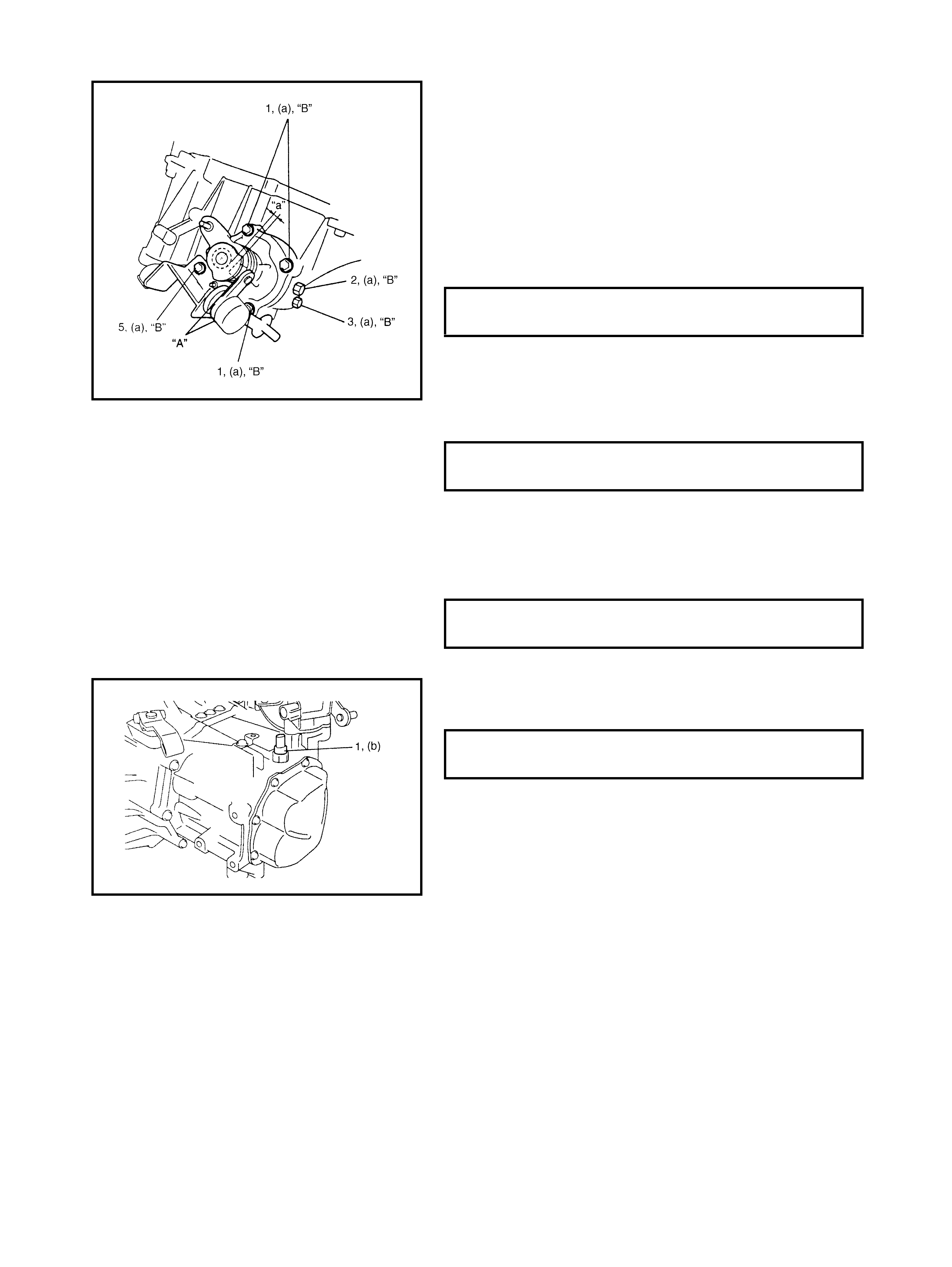
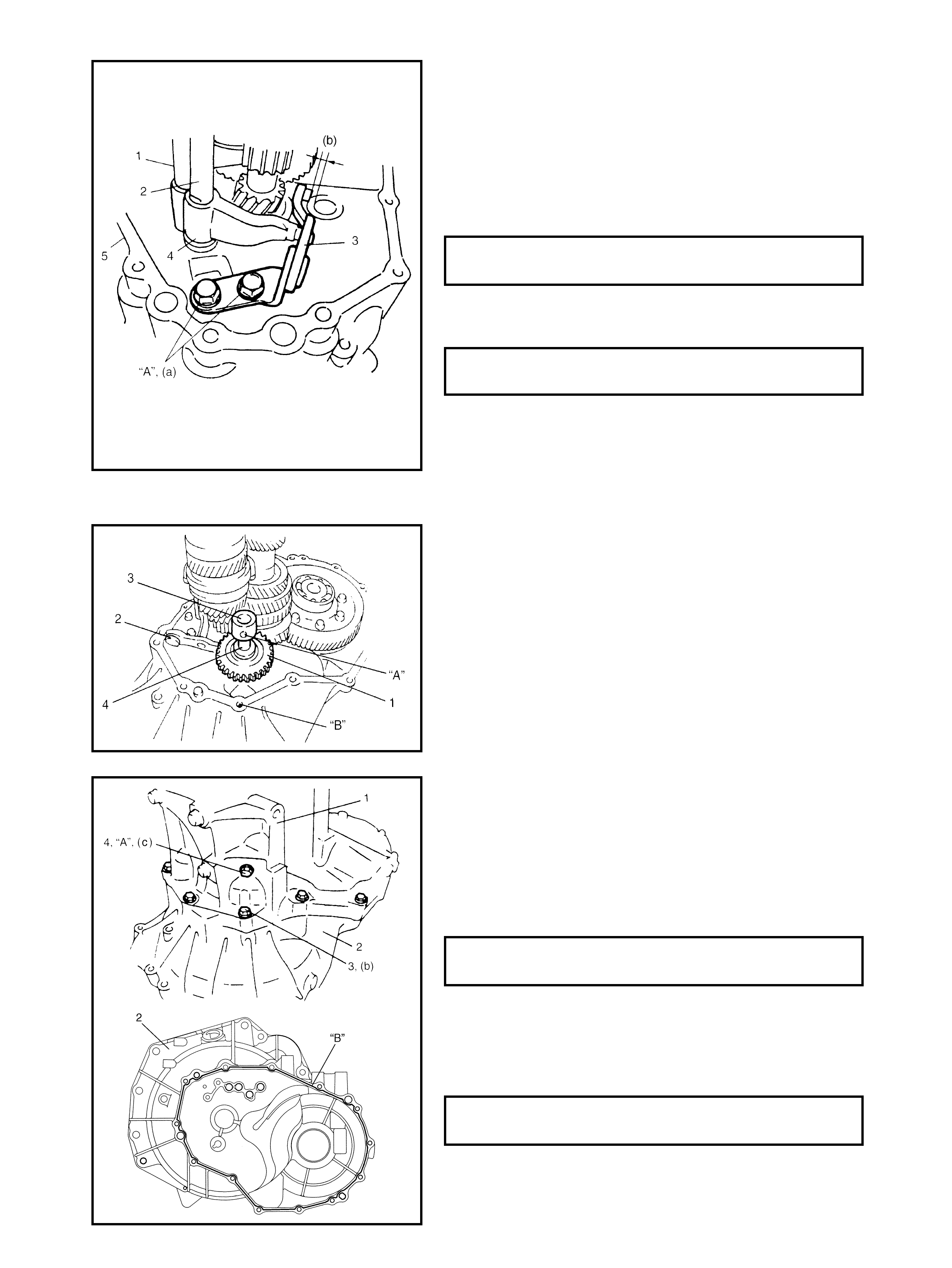
GEAR SHIFT AND SELECT SHAFT ASSEMBLY
1. Clean the mating surface of the guide case.
2. Appl y grease “A” to the s ele ct lever shaft bush and the
select lever boss. Install the gear shift and the select
shaft assem bly with a new gasket into the transaxle.
“A”: Lithium grease
3. Apply sealant to the gear shift guide case No. 2 bolt
(5). Tighten the gear shift guide case No. 1 bolts (1)
and the No. 2 bolt (5) to the specified torque at the
position that clearance “a” is within 1 - 1.5 mm.
4. Install the washe r and the gear shift inter lock bo lt (2) to
which sealant “B” has been appl ied and then tighten it
to the specified torque.
“B”: Sealant - Three Bond No. 1215
5. Install the washer and the 5th t o reverse interlock guide
bolt (3), to which sealant “B” has been applied and
then tighten it to the specified torque
“B”: Sealant - Three Bond No. 1215
6. Tighten the backup light switch (1) to the specified
torque.
7. Check the input shaft f or rotation in each gear position.
8. Also confirm the function of the back up light switch in
reverse position using the ohmmeter.
GUIDE CASE BOLT (a)
TORQUE SPECIFICATION 23.0 Nm
GEAR SHIFT INTERLOCK BOLT (a)
TORQUE SPECIFICATION 23.0 Nm
5th TO REVERSE INTERLOCK BOLT (a)
TORQUE SPECIFICATION 23.0 Nm
BACKUP LIGHT SWITCH (b)
TORQUE SPECIFICATION 19.0 Nm
5. REQUIRED SERVICE MATERIAL
6. SPECIAL TOOLS
NOTE: Refer to Section 0A GENERAL INFORMATION – 7. CONSOLIDATED TOOLS for a detailed list of
special tools and the local equivalent if one is available.
Material Recommended product Use
Lithium grease Lithium grease •Oil seal lips
•O-rings
•Select lever boss
•Select lever shaft bush
•Gear shift contro l cable end
Sea lant Three Bon d No. 1216B •Oil drain plug and filler/level plug
•M ating surface of transa xle case
•M ating surface of side cover
•Gear shift interlock bolt
Sea lant Three Bon d No. 1215 •Locating spring bolts
•Gear shift interlock bolt
•5th to revers e gear interlock guide
bolt
Thread lock cement THRE AD LOCK 1322 •Reverse gear shift lever bolts
•Oil gutter bolt
•Shift fork bolt
•Reverse shaft bolt
•Final gear bolts
09900-06107 09900-20607 09900-20701 09913-60910
Snap ring pliers
(Opening type) Dial gauge Magneti c stand Bearing puller
09913-75510 09913-80113 09913-84510 09922-85811
Bearing installer Bearing installer Bearing installer Spring pin remover
4.5 mm
09923-74510 09923-78210 09924-74510 09925-18011
Bea ring remover Beari ng installer I nsta ller attachment Bearing installer
09925-68210 09925-78210 09925-88210 09925-98221
Bear ing outer ra ce
installer Spring pin remover 6 mm Bearing puller attachment Bearing installer
09927-76010 09930-30104 09940-53111 09940-54910
Gear holder Sliding shaft Bearing installer Sensor rotor installer
09941-64511 09951-16060 09951-76010
Bearing remover Bush remover Bearing installer