
SECTION 7B - AUTOMATIC TRANSAXLE
WARNING:
For vehicles equip ped wit h Suppl ement Restraint (Airbag) System
• Service on and around the airbag system components or wiring must be performed only by
an authorised H OLDEN retailer. R efer to Section 10B AIRBAG SYSTEM COMP ONENTS AND
WIRING LOCATION VIEW in GENERAL DESCRIPTION in order to confirm whether you are
performing service on or near the airbag system components or wiring. Please observe all
W ARNINGS and SERVICE PRECAUTIONS, refer to Section 10B ON-VEHICLE SERVICE before
performing service on or around the airbag system components or wiring. Failure to follow
WARNINGS could result in unintentional activation of the system or could render the syste m
inoperative. Either o r t hese two conditions may result in severe injury.
• Techni cal servi ce work must not be started for at least 90 seconds after the igni tion switch is
turned to the “LOCK” position and the negative cable is disconnected from the battery. Oth-
erwise, the system may be activated by reserve energy in the Sensing and Diagnostic Mod-
ule (SDM).
IMPORTANT:
Prior to connecting Tech 2 to the vehicle, refer to Section 0C TECH 2.
1. GENERAL DESCRIPTION
1.1 SPECIFICATIONS
1.2 CLUTCH/BRAKE/PLANETARY GEAR
Functions
1.3 TABLE OF COMPONENT OPERATION
1.4 ELECTRONIC SHIFT CONTROL SYSTEM
1.5 TRANSMISSION CONTROL MODULE
(TCM)
Operation Of Shift Solenoid Valves,
Timing Solenoid Valve and TCC
Solenoi d Val ve 3
Automatic Gear Shift Diagram
Gear Shift Diagram [A] and TCC
Lock-up Diagram [B]
2. DIAGNOSIS
2.1 GENERAL DESCRIPTION
2.2 ON-BOARD DIAGNOSTIC SYSTEM
2.3 PRECAUTION IN DIAGNOSING
TROUBLE
2.4 AUTOMATIC TRANSAXLE DIAGNOSTIC
FLOW TABLE
Customer Problem Inspection Form
(Example)
2.5 O/D OFF - LAMP CHECK
2.6 DIAGNOSTIC TROUBLE CODE (DTC)
CHECK
DTC Check Using Tech 2
DTC Check Not Using Tech 2
2.7 DIAGNOSTIC TROUBLE CODE (DTC)
CLEARANCE
DTC Clearance Using Tech 2
DTC Clearance Not Using Tech 2
2.8 DIAGNOSTIC TROUBLE CODE (DTC)
TABLE
2.9 FAIL SAFE TABLE
2.10 VISUAL INSPECTION
2.11 AUTOMATIC TRANSAXLE BASIC
CHECK
2.12 TROUBLE DIAGNOSIS TABLE
Trouble Diagnosis Table-1
Trouble Diagnosis Table-2
Trouble Diagnosis Table-3
2.13 ROAD TEST
Troubleshooting
2.14 MANUAL ROAD TEST
Troubleshooting
2.15 ENGINE BRAKE TEST
Troubleshooting
2.16 STALL TEST
Troubleshooting
2.17 TIME LAG TEST
Troubleshooting
2.18 LINE PRESSURE TEST
Automatic Transmission
Line Pressure
Troubleshooting

2.19 P RANGE TEST
Troubleshooting
2.20 DIAGNOSTIC FLOW TABLE A-1: NO
GEAR SHIFT TO O/D
System Description
Troubleshooting
2.21 DIAGNOSTIC FLOW TABLE A-2: NO
LOCK-UP OCCURS
System Description
Troubleshooting
2.22 DIAGNOSTIC FLOW TABLE A-3: O/D
OFF LAMP CIRCUIT CHECK (O/D OFF
LAMP LIGHTS STEADILY)
Wiri ng Diagra m
Circuit Description
Troubleshooting
2.23 DIAGNOSTIC FLOW TABLE A-4: O/D
OFF LAMP CIRCUIT CHECK (O/D OFF
LAMP DOES NOT LIGHT AT ALL)
Wiri ng Diagra m
Circuit Description
Troubleshooting
2.24 DIAGNOSTIC FLOW TABLE A-5: TCM
POWER AND GROUND CIRCUIT
CHECK
Wiri ng Diagra m
Troubleshooting
2.25 DTC P0705/DTC NO.34 TRANSMISSION
RANGE SENSOR CIRCUIT
MALFUNCTION
Wiri ng Diagra m
DTC Detecting Condition and
Trouble Area
DTC Confirmation Procedure
Troubleshooting
2.26 DTC P0710/DTC NO.36 OR 38
TRANSMISSION FLUID
TEMPERATURE SENSOR CIRCUIT
MALFUNCTION
Wiri ng Diagra m
DTC Detecting Condition
and Trouble Area
DTC Confirmation Procedure
Troubleshooting
2.27 DTC P0715/DTC NO.14 INPUT/TURBINE
SPEED SENSOR CIRCUIT
MALFUNCTION
Wiri ng Diagra m
DTC Detecting Condition
and Trouble Area
DTC Confirmation Procedure
Troubleshooting
2.28 DTC P0720/DTC NO.31 OUTPUT SPEED
SENSOR (VSS) CIRCUIT
MALFUNCTION
Wiri ng Diagra m
DTC Detecting Condition and
Trouble Area
DTC Confirmation Procedure
Troubleshooting
2.29 DTC P0725/DTC NO.35 ENGINE SPEED
INPUT CIRCUIT MALFUNCTION
Wiring Diagram
DTC Detecting Condition and
Trouble Area
DTC Confirmation Procedure
Troubleshooting
2.30 DTC P0743/DTC NO.25 OR NO.26 TCC
SYSTEM ELECTRICAL
Wiring Diagram
DTC Detecting Condition and
Trouble Area
DTC Confirmation Procedure
Troubleshooting
2.31 DTC P0748/DTC NO.41 OR NO.42
PRESSURE CONTROL SOLENOID
ELECTRICAL
Wiring Diagram
DTC Detecting Condition and
Trouble Area
DTC Confirmation Procedure
Troubleshooting
2.32 DTC P0753/DTC NO.21 OR NO.22 SHIFT
SOLENOID-A (NO.1) ELECTRICAL
2.33 DTC P0758/DTC NO.23 OR NO.24 SHIFT
SOLENOID-B (NO.2) ELECTRICAL
Wiring Diagram
DTC Detecting Condition and
Trouble Area
DTC Confirmation Procedure
Troubleshooting
2.34 DTC P0785/DTC NO.13 TIMING
SOLENOID
Wiring Diagram
DTC Detecting Condition and
Trouble Area
DTC Confirmation Procedure
Troubleshooting
2.35 DTC P1700/DTC NO.32 OR NO.33
THROTTLE POSITION SIGNAL
CIRCUIT MALFUNCTION
Wiring Diagram
DTC Detecting Condition and
Trouble Area
DTC Confirmation Procedure
Troubleshooting
2.36 DTC P1702/DTC NO.52 INTERNAL
MALFUNCTION OF TCM
DTC Detecting Condition and
Trouble Area
DTC Confirmation Procedure
Troubleshooting
2.37 DTC P1705/DTC NO.51 ENGINE
COOLANT TEMPERATURE SIGNAL
CIRCUIT MALFUNCTION
Wiring Diagram
DTC Detecting Condition and
Trouble Area
DTC Confirmation Procedure
Troubleshooting

2.38 DTC P1730/DTC NO.64 ENGINE TORQUE
SIGNAL CIRCUIT MALFUNCTION
Wiri ng Diagra m
DTC Detecting Condition and
Trouble Area
DTC Confirmation Procedure
Troubleshooting
2.39 DTC P1895/DTC NO.27 TORQUE
REDUCTION SIGNAL CIRCUIT
MALFUNCTION
Wiri ng Diagra m
DTC Detecting Condition and
Trouble Area
DTC Confirmation Procedure
Troubleshooting
2.40 TECH 2 DATA
Tech 2 Data Definitions
2.41 INSPECTION OF TCM AND ITS
CIRCUITS
Inspection
Terminal Arrangement of TCM
Connector (Viewed From
Harness Side)
3. ON-VEHICLE SERVICE
3.1 MAINTENANCE SERVICE
Fluid Level Check at Normal
Operating (Hot) Temperature (Hot
Check)
Fluid Level Check at Room (Cold)
Temperature (Cold Check)
Fluid Change
A/T Fluid Cooler Hoses
3.2 SELECTOR LEVER
Inspection
3.3 SELECT CABLE
Removal
Installation
Adjustment
3.4 TRANSMISSION RANGE SENSOR
(SHIFT SWITCH)
Adjustment And Inspect ion
3.5 OUTPUT SHAFT SPEED SENSOR (VSS)
Removal
Inspection
Installation
3.6 INPUT SHAFT SPEED SENSOR
Inspection
Removal
Installation
3.7 THROT TLE POSITION SENSOR
Inspection
3.8 ENGINE COOLANT TEMPERATURE
SENSOR
Inspection
3.9 O/D OFF SWITCH
Inspection
3.10 SOLENOID VALVES (SHIFT SOLENOID
VALVES, TCC SOLENOID VALVE AND
TIMING SOLENOID VALVE)
Removal
Inspection
Operation Check
Timing Solenoid Valve (Both Denso
and Aisin Type)
Installation
3.11 PRESSURE CONTROL SOLENOID
VALVE
Removal
Inspection
Installation
3.12 TRANSMISSION CONTROL MODULE
(TCM)
Removal
Installation
Learning Control Initialisation
Brief Learning
3.13 A/T RELAY
Inspection
3.14 TRANSMISSION FLUID TEMPERATURE
SENSOR
Inspection
Installation
3.15 DIFFERENTIAL SIDE OIL SEAL
Replacement
3.16 AUTOMATIC TRANSAXLE ASSEMBLY
Components
Removal
Installation
4. UNIT REPAIR
4.1 PRECAUTIONS
4.2 PART INSPECTION AND CORRECTION
TABLE
4.3 UNIT DISASSEMBLY
Components
Disassembly
Inspection

4.4 DISASSEMBLY/ASSEMBLY OF
SUBASSEMBLY
Oil Pump
Disassembly
Inspection
Assembly
Dir ect Clutch
Preliminary Check
Disassembly
Inspection
Assembly
Forward and Reverse Clutch
Preliminary Check
Disassembly
Inspection
Assembly
2nd Brake Piston
Disassembly
Assembly
Transaxle Rear Cover Assembly
(O/D and 2nd Coast Brake Piston
Disassembly
Inspection
Assembly
4.5 DIFFERENTIAL ASSEMBLY
Disassembly
Inspection
Assembly
Countershaft
Disassembly
Assembly
Valve Body
Disassembly
Assembly
Torque Converter Housing
Transaxle Case
Adjustment Before Unit Assembly
4.6 Unit Assembly
5. SPECIAL TOOLS
6. REQUIRED SERVICE MATERIAL

1. GENERAL DESCRIPTION
The automatic transaxle is an electronically controlled, fully automatic transaxle with 3 forward speeds plus
overdrive (O/D) and 1 reverse speed.
The torque converter is a 3-element, 1-step and 2-phase type and is equipped with an automatically con-
trolled lock-up mechanism.
The gear change device consists of a ravigneau type planetary gear unit, 3 multiple disc type clutches, 3 mul-
tiple disc type brakes and 2 one-way clutches.
The hydraulic pressure control device consists of a valve body assembly, pressure control solenoid valve (lin-
ear solenoid), 2 shift solenoid valves, TCC (lock-up) solenoid valve and a timing solenoid valve. Optimum line
pressure, complying with engine torque, is produced by the pressure control solenoid valve depending on a
contr ol s ignal from the tr ansmi ss ion control m odu le (T CM). T his makes it pos s ible to c ontrol the li ne press ur e
with a hi gh degree of accuracy i n accordan ce with eng ine power and r unning c onditions, a chieving s mooth
shifting characteristics and high efficiency.
A clutc h-to-clu tch control system i s provided f or shifting betwee n 3rd gear and 4t h gear. This clutch -to-clutc h
control system functions optimally, so that the hydraulic pressure controls indicated below are activated.
i. When upshifting from 3rd gear to 4th gear, to adjust the drain hydraulic pressure when releasing the
forward clutch, a timing solenoid valve is used to switch a hydraulic passage via an orifice to ano ther
passage during shifting.
ii. When downsh ifting from 4th ge ar to 3rd gear, to adjust the line pr essure applied to the forwa rd clutch
when it is engaged, a timing solenoid valve is used to switch a hydraulic passage via an orifice to
another passage during shifting.
iii. When upshifting from 3rd gear to 4th gear with the engine throttle opened, to optimise the line pressure
applied to the forward clutch when it is released, the learning control is processed to compensate the
switching timing solenoid when shifting.
iv. When downshifting from 4th gear to 3rd gear with the engine throttle opened, to optimise the line pres-
sure a pplie d to the fo rward cl utch wh en enga ging the forward c lutc h, the lea rning c ontrol is proc essed
to compensate the line pressure when shifting.
Employing a ravigneau type planetary gear unit, this clutch-to-clutch control system greatly simplifies the con-
struction to produce a lightweight and compact transaxle.
A line pressure learning control is conducted to provide optimum shifting time when upshifting with the engine
throttl e op ened . If a l ong u pshifting time is dete cte d, the su bse que nt l ine press ure applie d duri ng upshi fting is
intensified. Conversely, if a short upshifting time is detected, the subsequent line pressure applied during
upshifting is lessened.
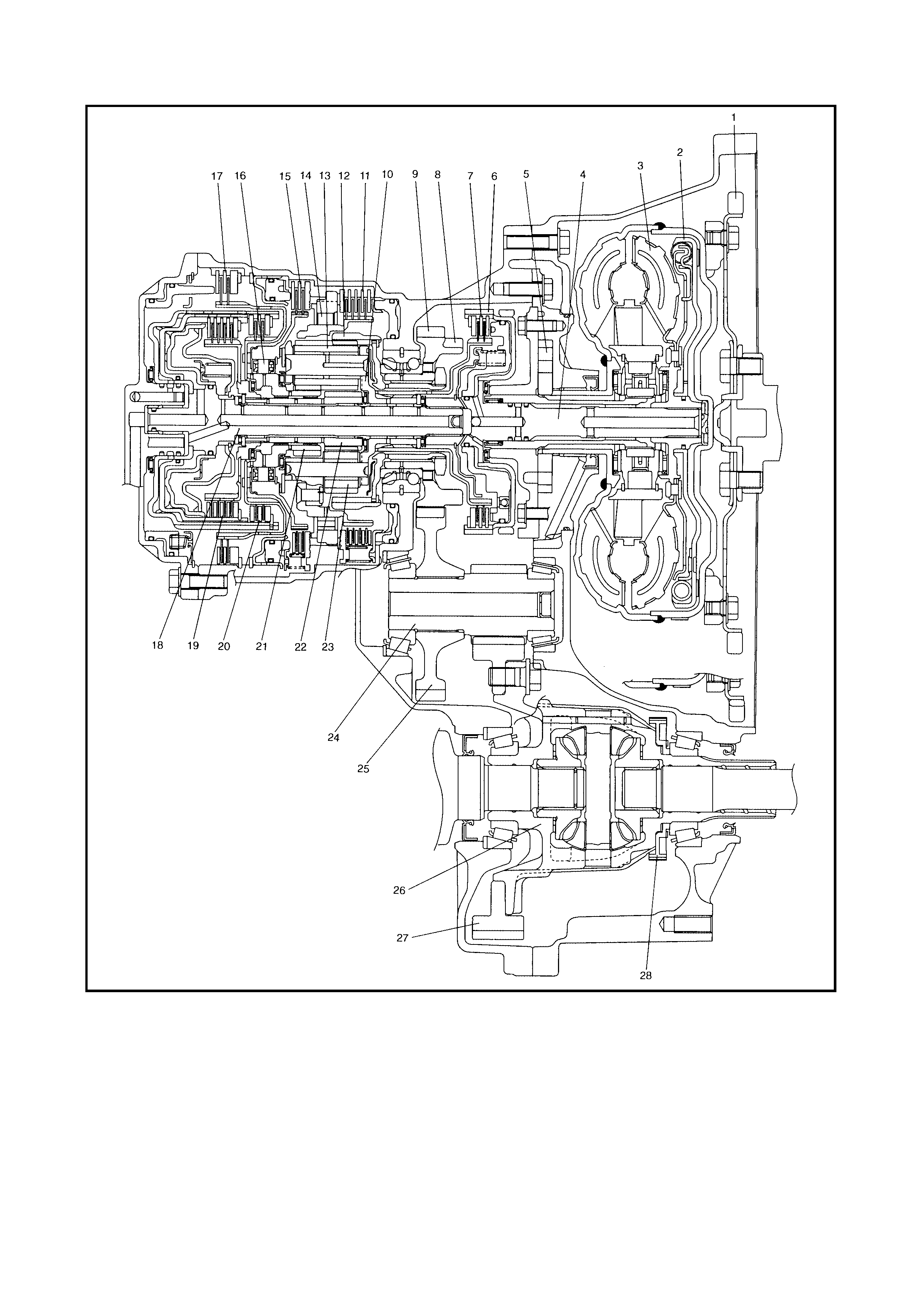
Legend
1. Drive plate 10. Planet carrier 21. Rear sun gear
2. Torque converter clutch (TCC) 11. 1st and reverse brake 22. Front sun gear
3. Torque converter 12. Ring gear 23. Short planet pinion
4. Input shaft 13. Long planet pinion 24. Countershaft
5. Oil pump 14. One-way clutch No.2 25. Reduction driven gear
6. Direct clutch drum (doubles
as sensor rotor for input shaft
speed sensor)
15. Second brake 26. Differential case assembly
16. One-way clutch No.1 27. Final gear
17. O/D and 2nd coast brake 28. Output shaft speed sensor
(VSS ) driv e gear
7. Direct clutch 18. Intermediate shaft
8. Parking lock gear 19. Forward clutch
9. Reduction drive gear 20. Reverse clutch
1.1 SP ECIFICATIONS
Item Specifications
Torque
converter Type
Stall torque ratio 3-element, 1-step, 2-phase type (with TCC (lock-up) mechanism)
1.9 – 2.1
Oil pump Type
Drive system Internal involute gear type oil pump (non crescent type)
Engine driven
Gear
change
device
Type Forward 4-step, reverse 1-step planetary gear type
Shift position P range Gear in neutral, output shaft fixed, engine start
R range Reverse
N range Gear in neutral, engine start
D range
(O/D ON) Forward 1st ↔ 2nd ↔ 3rd ↔ 4th (O/D)
automatic gear change
D range
(O/D OFF) Forward 1st ↔ 2nd ↔ 3rd ← 4th
automatic gear change
2 range Forward 1st ↔ 2nd ← 3rd
automatic gear change
L range Forward 1st ← 2nd ← 3rd reduction, and fixed at 1st
gear
Gear
ratio 1st 2.875 Number of teeth Front sun gear: 24
2nd 1.568 Rear sun gear: 30
3rd 1.000 Long planet pinion: 20
4th
(overdrive
gear)
0.697 Short planet pinion: 19
Ring gear: 69
Reverse
(reverse gear) 2.300
Control elements Wet type multiple-disc clutch... 3 sets
Wet type multiple-disc brake... 3 sets
One-way clutch... 2 sets
Reduction gear ratio 1.019
Final gear reduction
ratio 4.277
Lubrication Lubrication system Force feed system by oil pump
Cooling Cooling system Radiator assisted cooling (water-cooled)
Fluid used DEXRON
-III
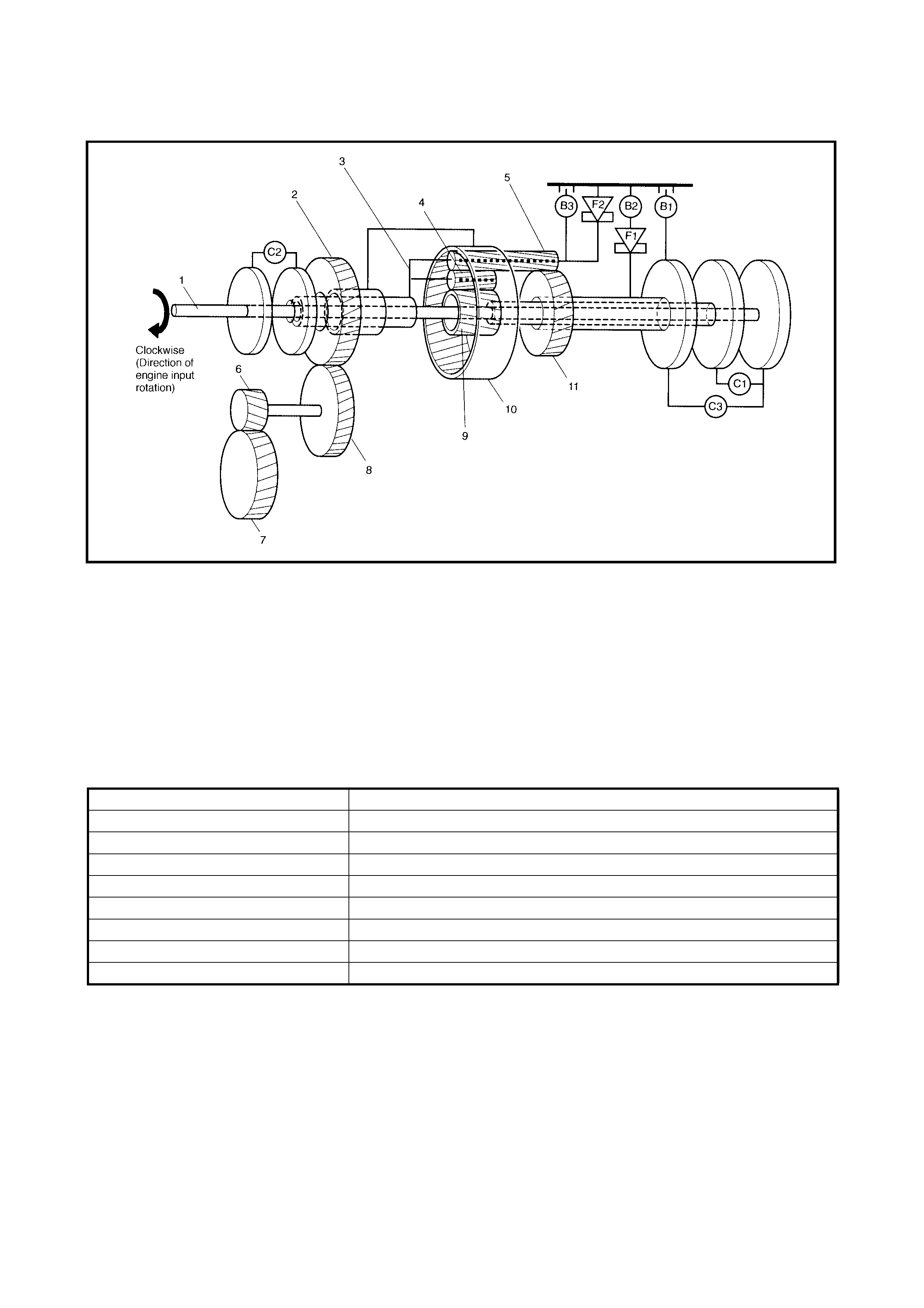
1.2 CLUTCH/BRAKE/PLANETARY GEAR
Legend
FUNCTIONS
1. Input shaft and intermediate 7. Final driven gear C3: Reverse clutch
shaft 8. Reduction driven gear B1: O/D and 2nd coast brake
2. Reduction drive gear 9. Front sun gear B2: 2nd brake
3. Planet carrier 10. Ring gear B3: 1st and reverse brake
4. Short planet pinion 11. Rear sun gear F1: One-way clutch No.1
5. Long planet pinion C1: Forward clutch F2: One-way clutch No.2
6. Final drive gear C2: Direct clutch
PART NAME FUNCTION
Forward clutch Meshes intermediate shaft and front sun gear
Direct clutch Meshes input shaft and planet carrier
Reverse clutch Meshes intermediate shaft and rear sun gear
O/D and 2nd coast brake Fixes rear sun gear
2nd brake Fixes rear sun gear
1st and r everse brake Fixes planet carrier
One-way clutch No.1 Prevents rear sun gear from turning counterclockwise
One-way clutch No.2 Prevents planet carrier from turning counterclockwise
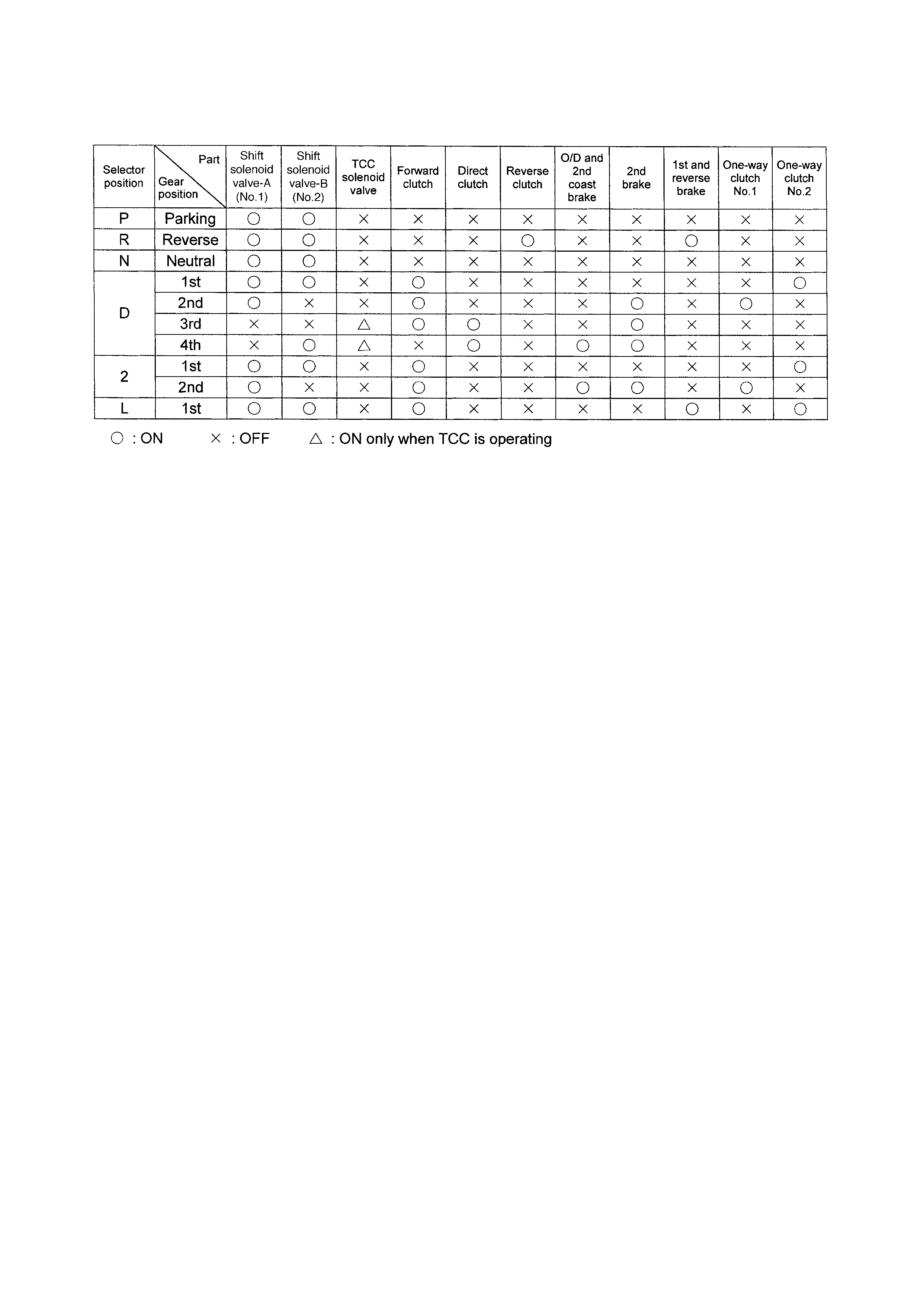
1.3 TABLE OF COMPONENT OPERATI ON
1.4 ELECTRONIC SHIFT CONTROL SYSTEM
Legend
1. Engine 10. Brake light (stop lamp) switch 17. Transmission fluid
temp eratur e se nsor
2. Transaxle 11. Input shaft speed sensor
3. O/D OFF lamp 12. Transmission range sensor 18. TCC (lock-up) solenoid valve
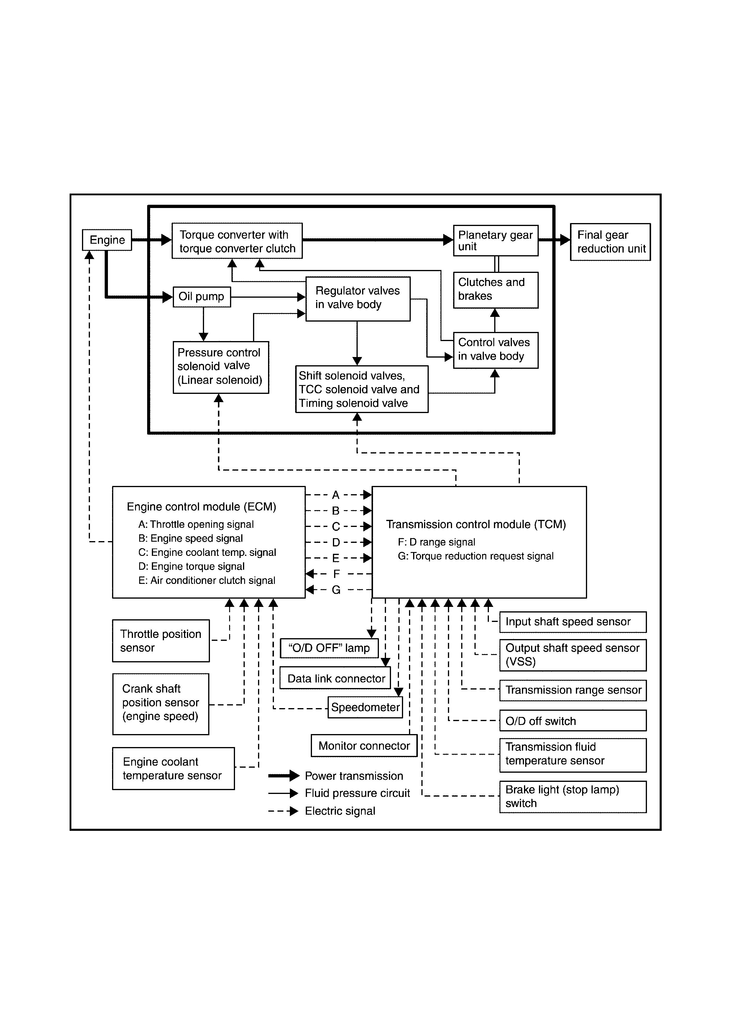
4. Throttle position (TP) sensor 13. Pressure control solenoid 19. Output shaft speed sensor
5. Diagnosis connector No. 2 valve (VSS)
6. A/T relay 14. Shift solenoid valve-A (No.2) 20. Engine coolant temperature
7. TCM 15. Shift solenoid valve-B (No.1) (ECT) sensor
8. ECM 16. Timing solenoid valve 21. Data link connector (DLC)
9. O/D off switch
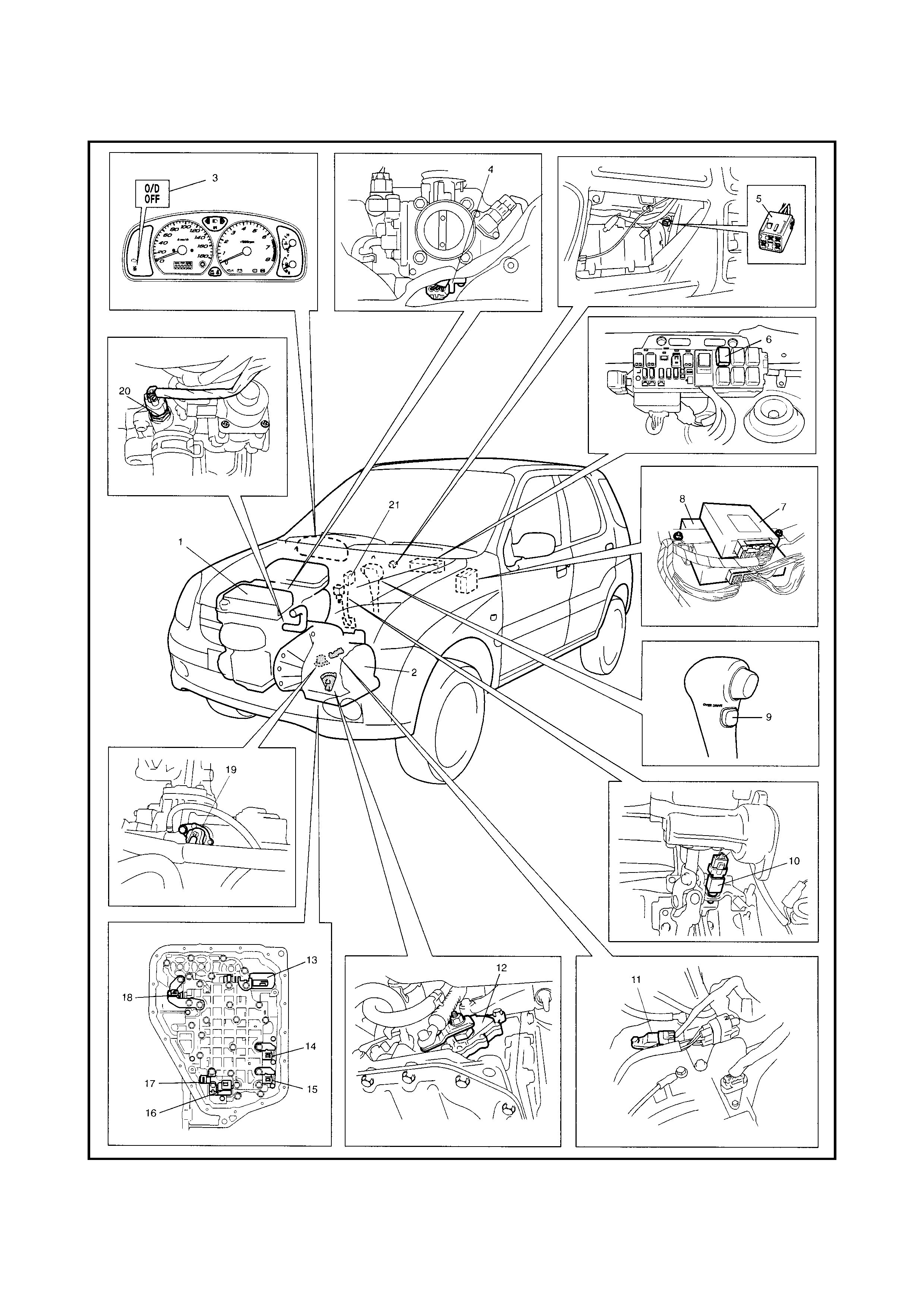
1.5 TRANSMISS ION CONTROL MODULE (TCM)
Legend
1. TC M 9. ECM 18. Pre ssure control s olenoid
2. Input shaft sp eed sensor 10. Speedometer valve
3. Output shaft speed sensor (in combination meter) 19. A/T
(VSS) 11. Transmission range sensor 20. Data link connector (DLC)
4. O/D off swit ch 12. Backup lamp 21. “O/D OFF” lamp
5. Diagnosis connector No. 2 13. Transmission fluid temperature 22. A/T relay
(colour in Bl ack) sens or 23. Ignition switch
6. Brake light (Stop lamp) 14. Shift solenoid valve-A (No.1) 24. Inhibitor switch
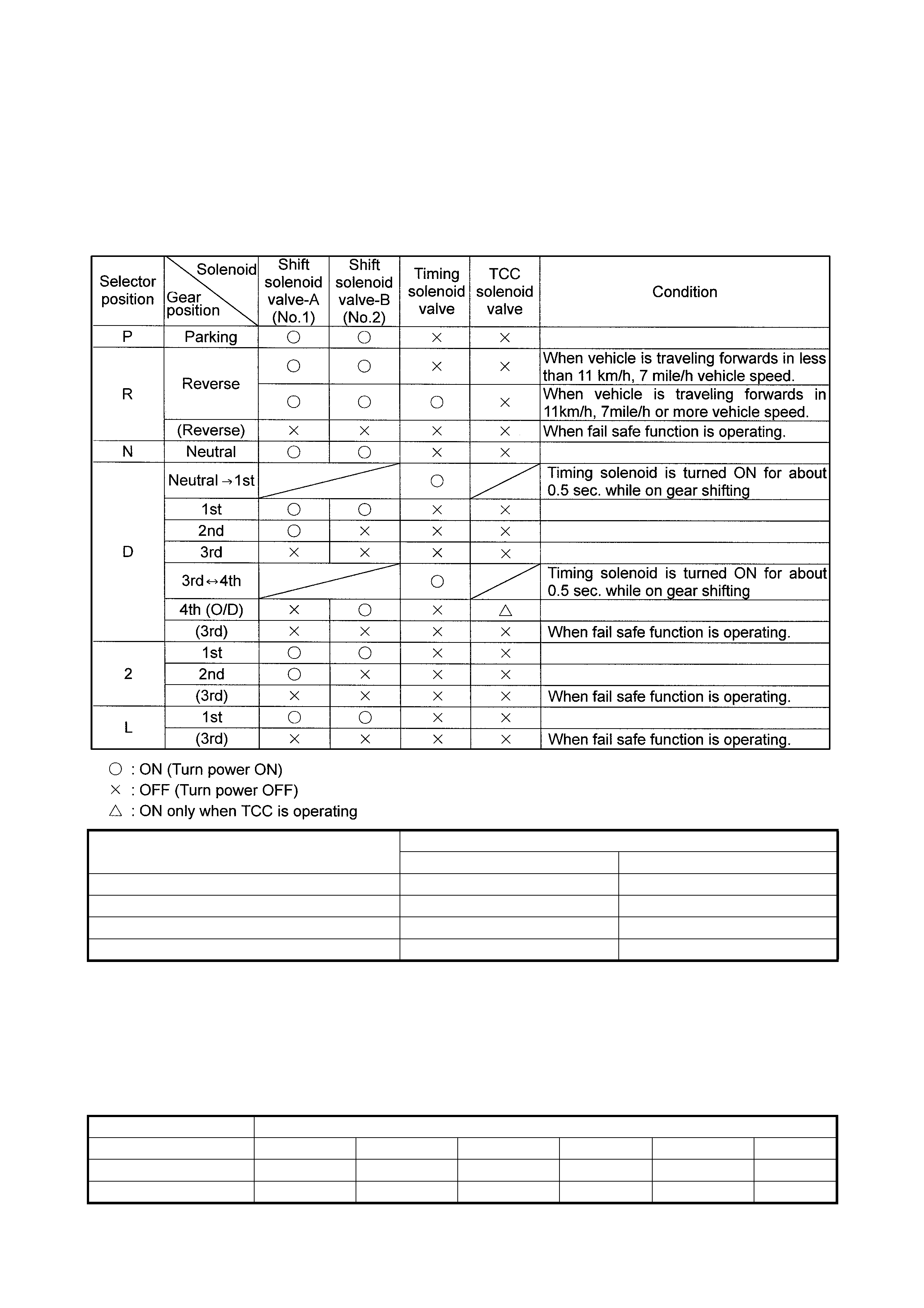
OPERATION OF SHIFT SOLENOID VALVES, TIMING SOLENOID VALVE
AND TCC SOLENOID VALVE
AUTOMATIC GEAR SHIF T DIAGRAM
The automatic shift schedule is shown below. If the selector lever is shifted to L range at a speed
higher than 48 km/h speed, 2nd gear will operate and only down shift to 1st when the vehicle speed
drops below 48 km/h.
Similarly, if the select lever is shifted to 2 range at a speed higher than 95 km/h, 3rd gear will operate
and only down shift to 2nd when the vehicle speed drops below 95 km/h.
7. Brake light switch 15. Shift solenoid valve-B (No.2) 25. Starter motor relay
(Stop lamp switch) 16. Timing solenoid valve 26. Terminal arrangement of TCM
connector
(viewed from harne ss)
8. ABS control module 17. TCC (lock-up) solenoid valve
Valve status
Turn power ON Turn power OFF
Shift solenoid valve-A (No.1) Close Open
Shift solenoid valve-B (No.2) Close Open
Timing solenoid Open Close
TCC (lock-up) solenoid Close Open
Shift
Throttle opening 1→22→33→44→33→22→1
Full throttle km/ h 48 95 No up shift 137 89 38
Closed throttl e km/h 12 24 43 29 18 10
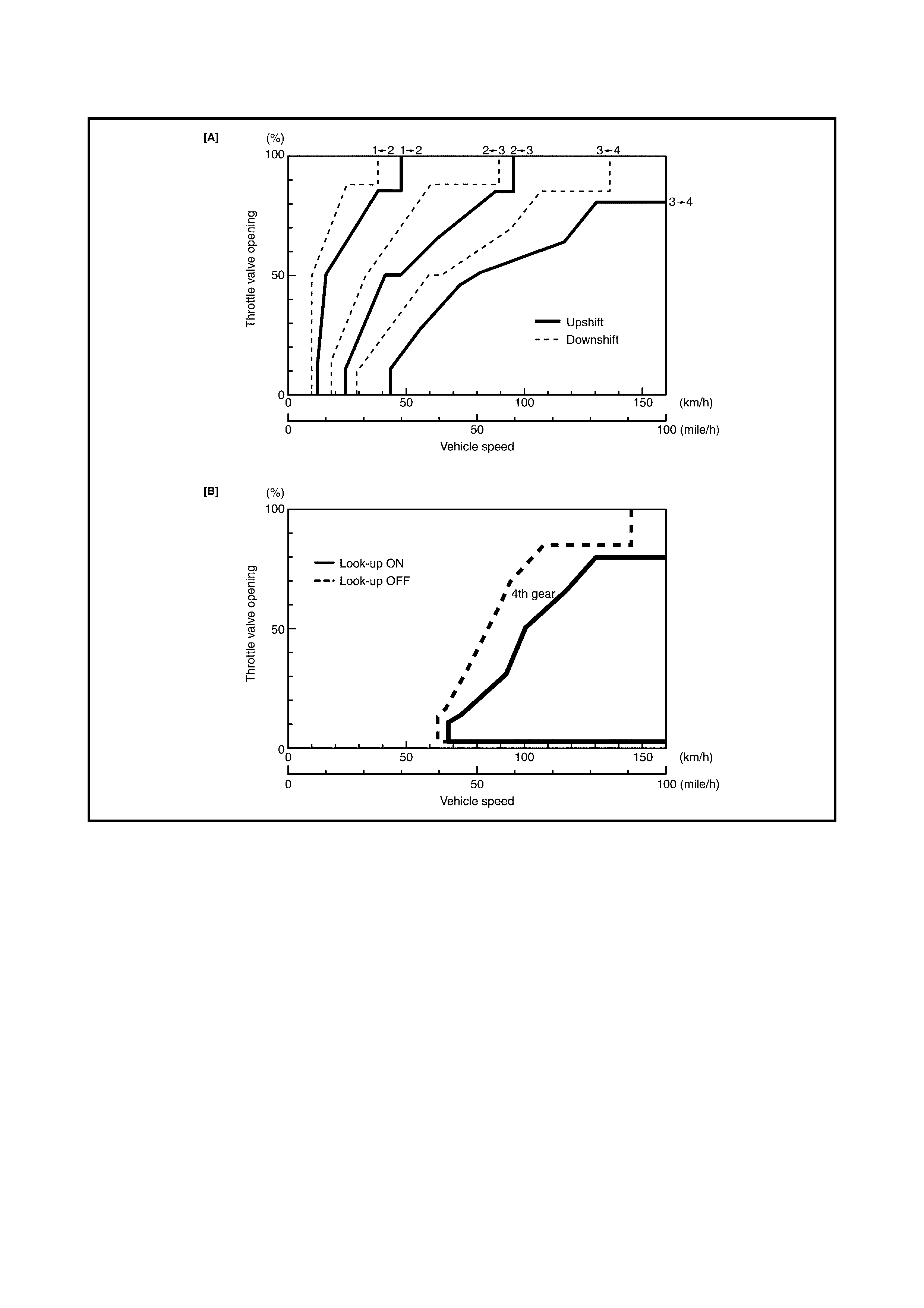
GEAR SHIFT DIAGRAM [A] AND TCC LOCK-UP DIAGRAM [B]
2. DIAGNOSIS
2.1 GENERAL DESCRIPTION
This vehicle is equipped with an electronic transaxle control system, which controls the automatic shift
up and shift down timing, TCC operation, etc. suitable to the vehicle drivin g conditions.
TCM has an On-B oard Diagn osis Syst em which detect s a malfunction in this system.
When diagnosing a trouble in the A/T transaxle, be sure to have full understanding of the outline of
2.2 ON-BOARD DIAGNOSTIC SYSTEM and each item in 2.3 PRECAUTIONS IN DIAGNOSING
TROUBLE and execute diagnosis according to 2.4 AUTOMATIC TRANSAXLE DIAGNOSTIC FLOW
TABLE in this Section to obtain correct result smoothly.
2.2 ON-BOARD DIAGNOSTIC SYSTEM
The TCM has the follow ing functions in the automatic tran-
saxle control system:
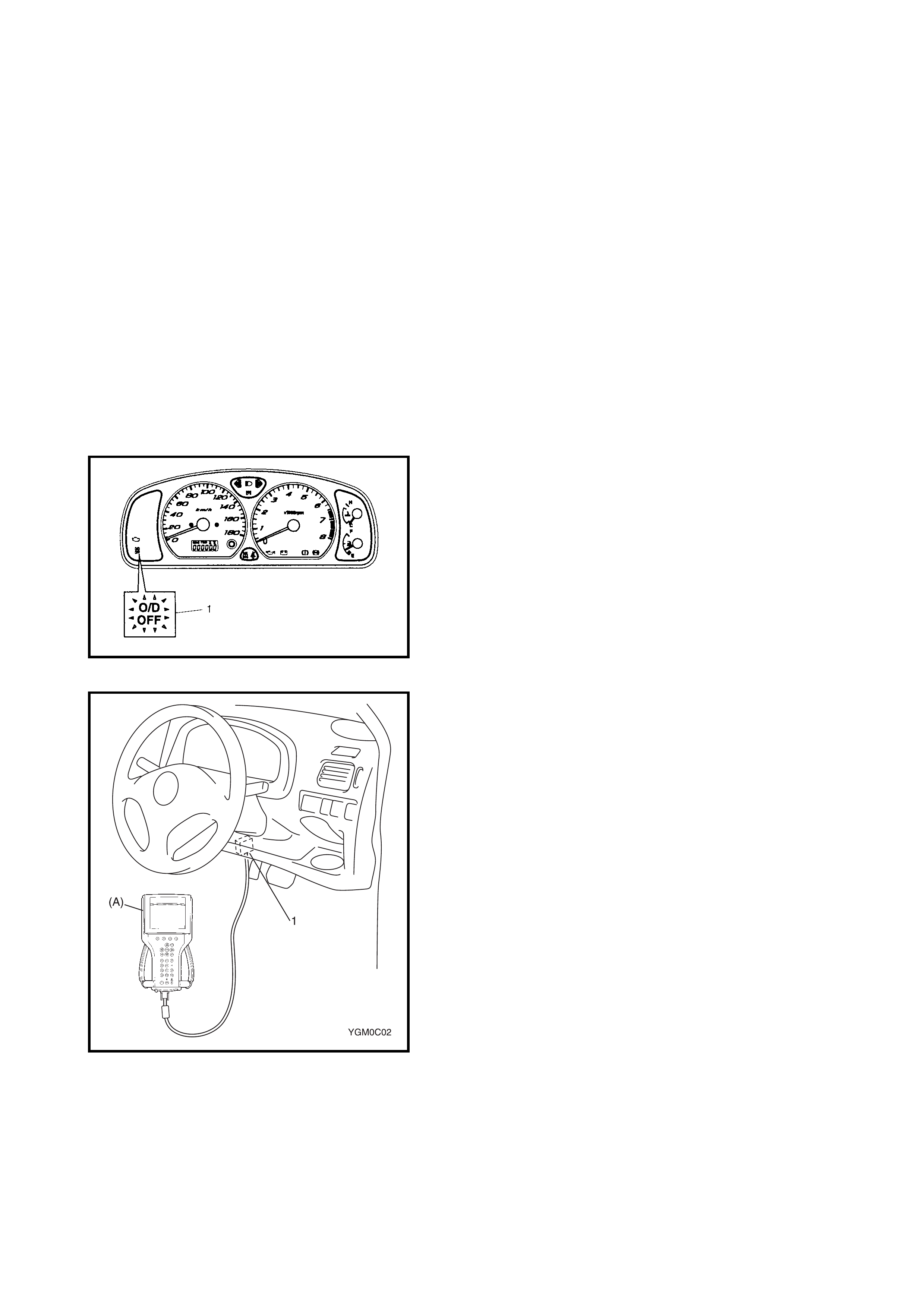
• When the ignition switch is turned ON with the O/D
OFF swit ch turned OFF an d no malfunction in the A/T
control system is detected, the O/D OFF lamp (1) lights
for about 2 seconds after the ignition switch is turned
ON then goes OFF for bulb check.
If the O/D off switch is ON, however , the O/D OFF lamp
remains ON to let the driver know that the gear has not
shifted to overdrive (4th gear).
• When the TCM detects a malfunction in the A/T control
system, the O/D OFF lamp (1) flashes and stores the
malfunction DTC in its memory.
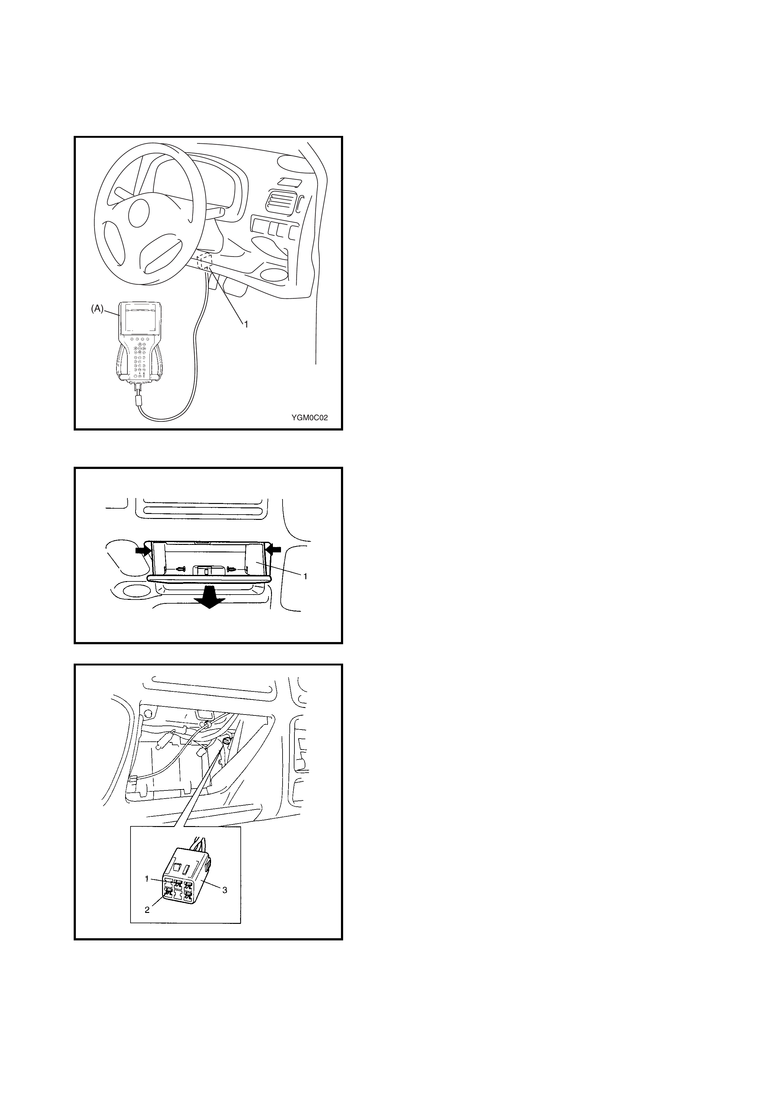
• It is possible to communicate with the TCM through the
data link connector (DLC) (1) using Tech 2 (A). (Diag-
nostic information can be checked and erased using
Tech 2.)
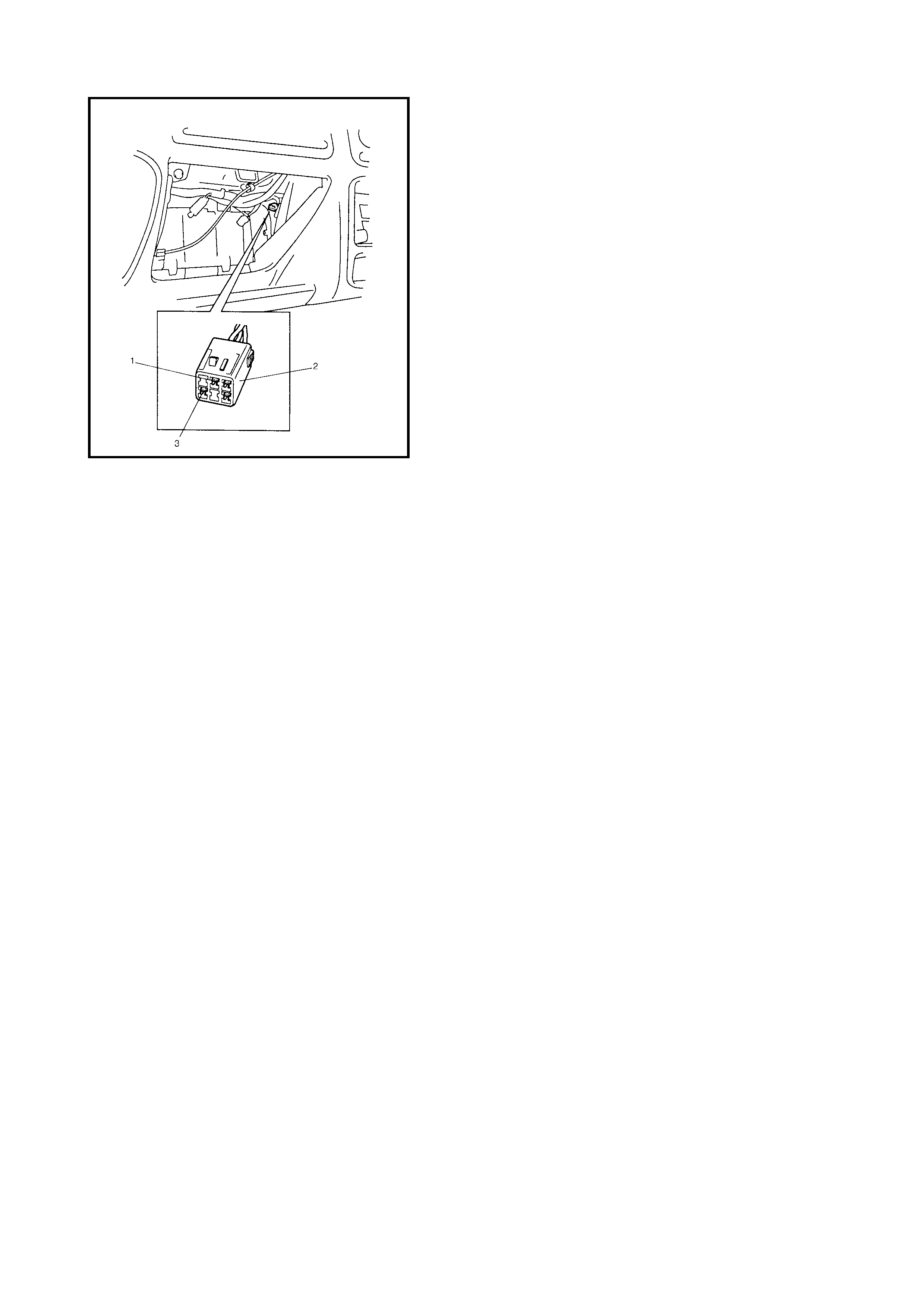
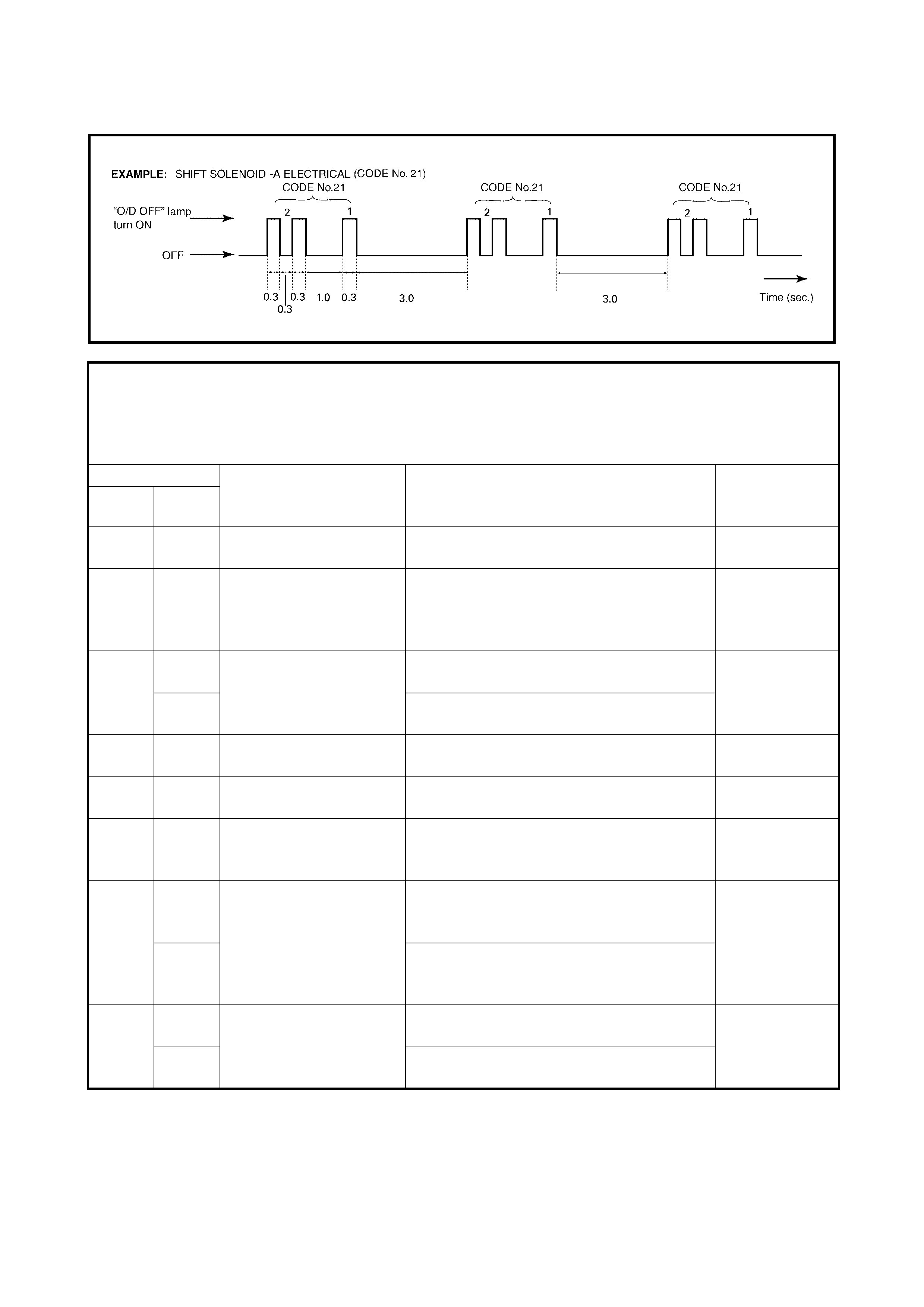
• It is also possible to output the DTC indicated by the
flashing O/D OFF lamp with the diagnosis switch termi-
nal (1) of the diagnosis connector No. 2 (2) grounded
(3).
If there is no malfunction DTC is stored in the TCM
memory, DTC No.12 is outputted repeatedly.
If one or more malfunction DTCs are stored in the TCM
memory, they are outputted three times per one code
starting from smallest code number in increasing order.
After all malfunction DTCs are outputted, all malfunc-
tion DTCs are outputted again in the same manner.
2.3 PRECA UTION IN DIAGNOSING TROUBLE
• Do not disc on nec t the connec tors fro m the EC M, th e batt ery c able fr om th e bat tery, the ECM gro und wire
harness from the engine or the main fuse before checking the diagnosis information stored in the ECM
memory.
Disconnection of these items will clear the memorised information in the ECM memory.
• Using Tech 2, the diagno st ic infor matio n stor ed in t he TCM memor y can b e chec ked a nd clea red. Be fore
using Tech 2, be sure to read the Operator’s (instruction) Manual supplied with it carefully to clearly under-
stand its functions and usage.
•Refer to Section 0A, 1.7 PRECAUTION FOR ELECTRICAL CIRCUIT SERVICE before undertaking
inspection and repairs.
• TCM and/or ECM replacement
i. When substituting a known-good TCM and/or ECM, check that all relays and actuators have resis-
tance of the specified value.
Neglecting this check may result in damage to a good TCM and/or ECM.
ii. When replacing the TCM with a used one, all learned contents, which have been stored in the TCM
memory by executing learning control, should be initialised after replacement, refer to LEARNING
CONTROL INITIALISATION in 3.12 TRANSMISSION CONTROL MODULE (TCM) in this Secti on.
Neglecting this initialisation may cause excessive shift shock.

2.4 AUTOMATIC TRANSAXLE DIAGNOSTIC FLOW TABLE
Refer to the following pages for the details of each step
Step Action Yes No
1. Customer Complaint Analysis
Perform customer complaint analysis referring
to the next page.
Was customer complaint analysis performed
according to instruction on the next page?
Go to Step 2. Perform customer com-
plaint analysis.
2. Diagnostic Trouble Code (DTC) Check,
Record and Clear anc e
Check for DTC referring to the next page.
Is there any DTC(s)?
Print DTC or write them
down and clear them by
referring to 2.8 DTC
CLEARANCE in this
Section.
Go to Step 3.
Go to Step 4.
3. Visual Inspection
Perform visual inspection referring to the next
page.
Is there a faulty condition?
Repair or replace
malfunction part.
Go to Step 11.
Go to Step 5.
4. Visual Inspection
Perform visual inspection referring to the next
page.
Is there any faulty condition?
Repair or replace
malfunction part.
Go to Step 11.
Go to Step 8.
5. Trouble Symptom Confirmation
Confirm trouble symptom referring to the next
page.
Is a trouble symptom identified?
Go to Step 6. Go to Step 7.
6. Rechecking and Record of DTC
Recheck for DTC referring to “DTC Check” in
this section.
Are there any DTC(s)?
Go to Step 9. Go to Step 8.
7. Rechecking and Record of DTC
Recheck for DTC referring to “DTC Check” in
this section.
Are there any DTC(s)?
Go to Step 9. Go to Step 10.
8. Automatic Transaxle Basic Inspection and
Trouble Diagnosis Table
Check and repair, refer to 2.11 A/T BASIC
CHECK and 2.12 TROUBLE DIAGNOSIS
TABLE in this Section.
Are the checks and repairs complete?
Go to Step 11. Check and repair
malfunctioning part(s).
Go to Step 11.
9. Troubleshooting for DTC
Check and repair according to applicable DTC
Flow Table.
Are the checks and repairs complete?
Go to Step 11. Check and repair
malfunctioning part(s).
Go to Step 11.
10. Check for Intermittent Problems
Check for intermittent problems, refer to the
next page.
Is there a faulty condition?
Repair or replace mal-
functioning part(s).
Go to Step 11.
Go to Step 11.
11. Final Confirmat ion Test
Clear DTC if any.
Perform final confirmation test, refer to the next
page.
Is there a problem symptom, DTC or abnormal
condition?
Go to Step 6. End.

1. Customer Complaint Analysis (See Customer Problem Inspection Form).
Record details of the problem (failure, complaint) and how it occurred as described by the customer.
Use of an inspection form, refer to CUSTOM ER PR OB LEM I N SPEC TI ON FOR M (E XAM PLE ) , will enable the
collecting of information required for proper analysis and diagnosis.
2. Diagnostic Trouble Code (DTC) Check, Record and Clearance.
First, refer to 2.6 DTC CHECK in this Section, check the DTC. If a DTC exists, print or write down the DTC
and then c lear the mal function DTC(s), refer to 2.7 DTC CLEAR ANCE in this S ection. Ma lfunc tion DTC in di-
cates a malfunction in the system but it is not possible to know if the malfunction is occurring now or has
occurred in the past and that the normal condition has been restored. To confirm, check the symptom, refer to
Step 5 then recheck the DTC according to Step 6.
Diagnos in g a tr oub le b as ed on th e DTC in thi s s tep on ly, or failu r e to cl ear th e DT C in t his st ep , ma y resu lt i n
a faulty diagnosis, trouble diagnosis of a normal circuit or difficulty in troubleshooting.
3 and 4. Visual Inspection.
As a pre liminary step, be sure to perform a visual check of the items that support the prop er function of the
engine and the automatic transaxle, refer to 2.10 VISUAL INSPECTION in this Section.
5. Trouble Symptom Confirmation.
Check trouble symptoms based on the information obtained in S tep 1, Customer Complaint Analysis and Step
2, DTC Check.
Also, reconfirm the DTC according to the DTC CONFIRMATION PROCEDURE described in each DTC Flow
Table.
6 and 7. Rechecking and Record of DTC.
Refer to 2.6 DTC CHECK in this Section for checking procedure.
8. Automatic Transmission Basic Check and Trouble Diagnosis Table.
Perform a basic check of the A/T according to the flow table, refer to 2.11 AUTOMATIC TRANSAXLE
BASIC CHECK in this Section firs t. When the end of the flow table has be en reached, ch eck the parts of the
syst em susp ected as a possi ble cause of pro blems t hen refe r to 2.12 TR OUBLE DIAGNOSIS TABLE in this
Section. Based on the symptoms appearing on the vehicle (symptoms obtained through steps of customer
complaint analysis, trouble symptom confirmation and/or A/T basic check) repair or replace the faulty parts.
9. Diagnostic Trouble Code Flow Table (See each DTC Flow Table).
Based on the DTC indicated in Steps 6/7, refer to 2.8 DIAGNOSTIC TROUBLE CODE TABLE in this Section,
locate the cause of the trouble, name ly in a sensor, switch, wire harness, connecto r, actuator, TCM or other
part and repair or replace the faulty parts.
10. Check for Intermittent Problem.
Check the parts where an intermittent trouble is likely to occur (e.g. wire harness, connector, etc.), refer to
Section 0A, 1.7 ELECTRICAL CIRCUIT INSPECTION PROCEDURE, INTERMITTENT AND POOR
CONNECTION and the related circuit of the DTC recorded in Step 2.
11. Final Confirmation Test.
Confir m that the pr oble m sympto m has been corre cted and th at the vehic le is free fr om an y abn ormal c ondi-
tions. If the repaired item(s ) is related to the malfunctio n DTC, clear the DTC once and check to ensure that
no malfunction DTC is still indicated.
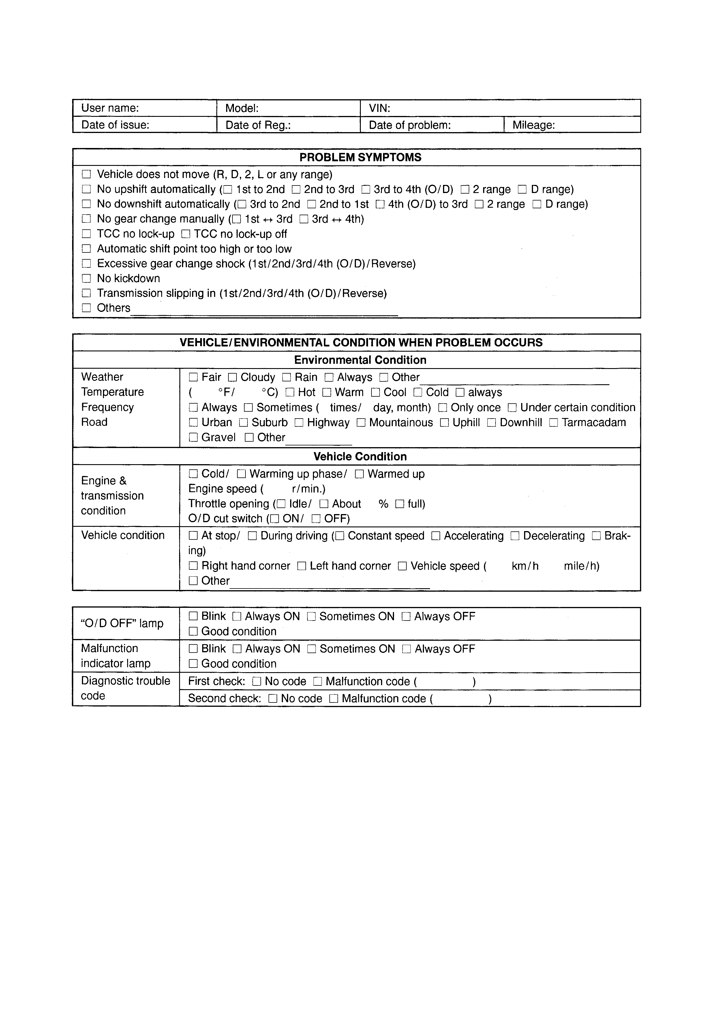
CUSTOMER PROBLEM INSPECTION FORM (EXAMPLE)
NOTE: The above form is a standard sample. It may be differ depending on requirements.
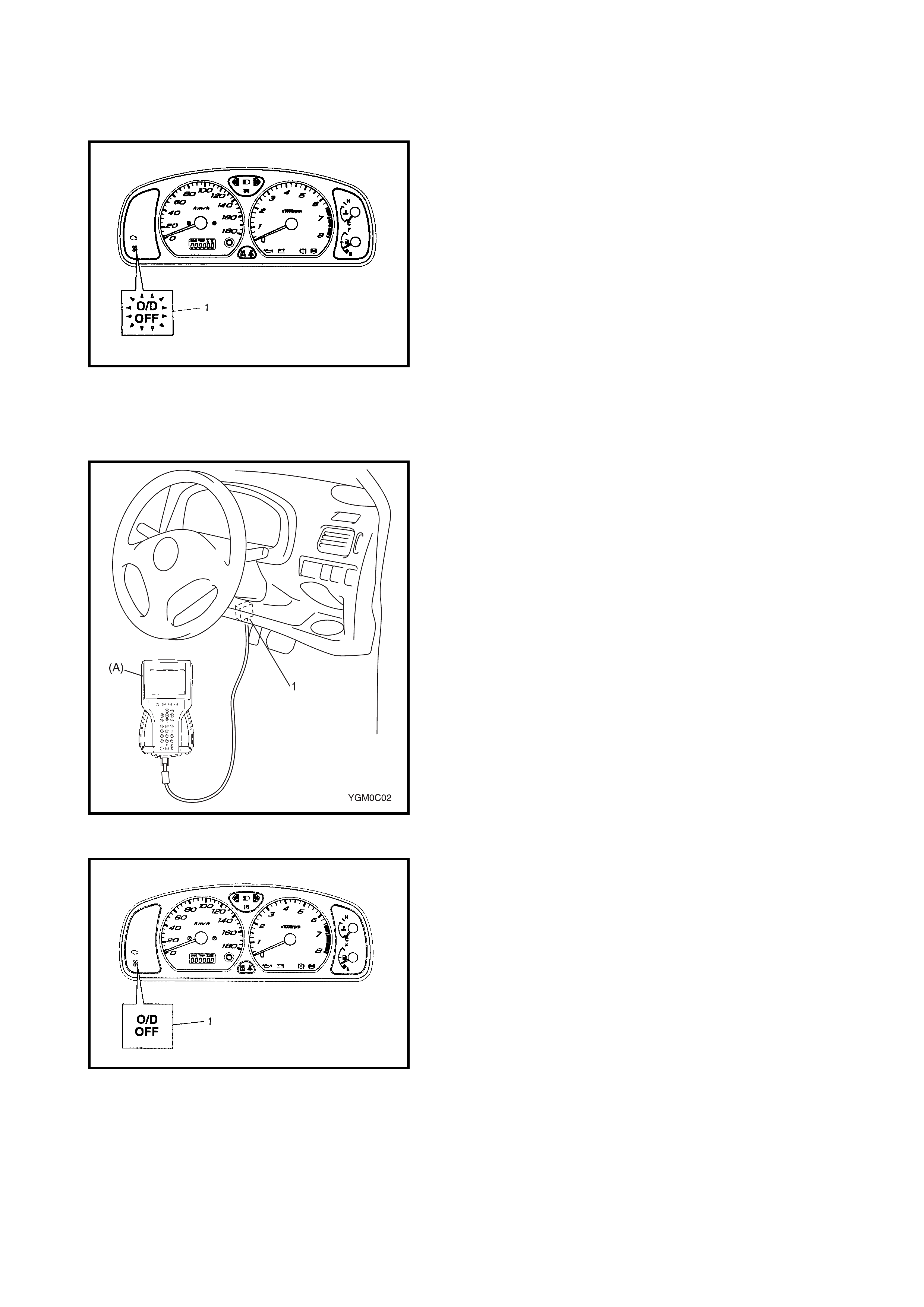
2.5 O/D OFF - LAMP CHECK
1. Turn the ignition switch ON.
2. Check that the O/D OFF lamp (1) lights for about 2 sec.
and then goes OFF.
If any faults are found, refer to
2.22 DIAGNOSTIC FLOW TABLE A-3 or
2.23 DIAGNOSTIC FLOW TABLE A-4 in this Section.
2.6 DIAGNOSTIC TROUBLE CODE (DTC) CHEC K
DTC CHECK USING TECH 2
1. Turn the ignition switch OFF.
2. Connect Tech 2 (A) to the data link connector (DLC) (1)
located in the un der side of the i ns trumen t panel o n th e
driver s side .
3. Turn the ignition switch ON.
4. Read the DTC according to the instructions displayed
on Tech 2 and note it. Refer to Tech 2 operator’s
manual for further details.
5. After completing the check, turn the ignition switch
OFF and disconnect Tech 2 from the data link
connector (DLC) (1).
DTC CHECK NOT USING TECH 2
1. Turn the ignition sw itch ON and make s ure that the O/
D OFF lamp (1) is OFF in the combination meter (with
O/D OFF switch OFF).
2. Turn the ignition switch OFF.
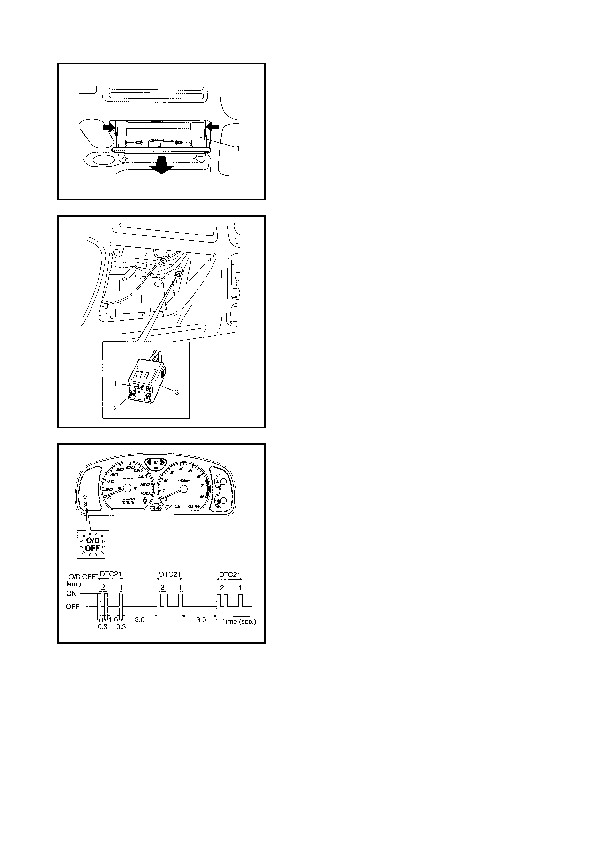
3. Remove the glove box (1) from the instrument panel.
4. Using a service wire, connect the diagnosis switch
terminal (1) and the ground terminal (2) of the
diagnosis connector No. 2 (3).
5. Turn the ignition switch OFF.
6. Read the DTC from the flashing pattern of the O/D
OFF lamp (1).
7. After completing the DTC check, turn the ignition
switch OFF and disconnect the service wire from the
diagnosis connector No. 2 (2).
2.7 DIAGNOSTIC TROUBLE CODE (DTC) CLEARANCE
DTC CLEARANCE USING TECH 2
1. Turn the ignition switch OFF.
2. Connect Tech 2 (A) to data link connector (DLC) (1)
located In underside of instrument panel on the drivers
side.
3. Turn the ignition switch ON.
4. Clear the DTC according to the instructions displayed
on Tech 2. Refer to Tech 2 operator’s manual for
further details.
5. After comple ting the clearanc e, turn the ignitio n switch
OFF and disconnect Tech 2 from the data link
connector (DLC) (1).
DTC CLEARANCE NOT USING TECH 2
1. Remove the glove box (1) from the instrument panel.
2. Turn the ignition switch ON.
3. Using service wire, repeat connection and disconnec-
tion be tween diagnosis switch te rminal (1) and ground
terminal (2) of diagnosis connector No. 2 (3) 5 times
with about 1 second interval within 10 seconds.
4. Perform DTC CHECK and confirm that only DTC
No.12 (DTC of normal condition) is displayed, refer to
2.8 DTC TABLE in this Section. If not, Repeat Step 3
and recheck.
2.8 DIAGNOSTIC TROUBLE CODE (DTC) TABLE
NOTE:
• Type I of DTC: DTC code which can be checked by using Tech 2
• Type II of DTC: DTC code which can be checked by flashing “O/D OFF” lamp in combination
meter with diagnosis connector No. 2 diagnosis terminal connected to ground.
• *1: Application of O/D OFF lamp flashing by TCM when the malfunction is detected.
DTC NO. DETECTING ITEM DETECTING CONDITION
(DTC will set when detecting:)
*1
“O/D OFF”
lamp flashing
Type I Type II
– 12 Normal (No malfunction
is detected.) ––
P0705 34 Transmission range sen-
sor circuit malfunction • No sensor signal is inputted.
or
• Multiple signals are inputted simulta-
neously
Applicable
P0710 36 Transmission fluid tem-
perature sensor circuit
malfunction
Sensor output voltage is too high (Circuit
open or shored to power circuit) Not applicab le
38 Sensor output voltage is too low (Circuit
shored to ground)
P0715 14 Input/Turbine speed sen-
sor circuit malfunction No sensor signal is detected although out-
put shaft speed sensor signal is detected. Applicable
P0720 31 Output speed sensor
(VSS) circuit malfunction No sensor signal is inputted although input
shaft speed sensor signal is inputted. Applicable
P0725 35 Engine speed input cir-
cuit malfunction No engine speed signal is inputted although
engine is running and engine temperature
senso r si gna l is in norma l cond iti on .
Applicable
P0743 25 Torque converter clutch
system electrical Voltage of TCC solenoid terminal is high
although TCM is commanding TCC sole-
noid to turn OFF.
Not applicab le
26 Voltage of TCC solenoid terminal is low
although TCM is commanding TCC sole-
noid to turn ON.
P0748 41 Pressure control sole-
noid electrical No electric flow is detected on solenoid cir-
cuit. Applicable
42 Too much electric flow is detected on pres-
sure control solenoid circuit.

DTC NO. DETECTING ITEM DE TECTING CONDITION
(DTC will set when detecting:)
*1
“O/D OFF”
lamp flashing
Type I Type II
P0753 21 Shift solenoid-A (No.1)
electrical Voltage of shift solenoid terminal is high
although TCM is commanding shift solenoid
to turn OFF.
Applicable
22 Voltage of shift solenoid terminal is low
although TCM is commanding shift solenoid
to turn ON.
P0758 23 Shift solenoid-B (No.2)
electrical Voltage of shift solenoid terminal is high
although TCM is commanding shift solenoid
to turn OFF.
Applicable
24 Voltage of shift solenoid terminal is low
although TCM is commanding shift solenoid
to turn ON.
P0785 13 Timing solenoid • Voltage of timing solenoid terminal is
high although TCM is commanding tim-
ing solen oid to turn OFF.
or
• Volt age o f t i mi n g s ol e noid t e rm in al is lo w
although TCM is commanding timing
solenoid to turn ON.
Applicable
P1700 32 Throttle position signal
circuit malfunction Too short low signal of pulse signal from
ECM to TCM continues out of specification. Applicable
33 Too long low signal of pulse signal from
ECM to TCM continues out of specification.
P1702 52 Internal malfunction of
TCM Calc ulat io n of c ur rent dat a st or ed in T CM i s
not correct compared with pre-stored
checking data in TCM.
Applicable
P1705 51 Engine coolant tempera-
ture signal circuit mal-
function
• Too long high signal of pulse signal from
ECM to TCM continues out of specifica-
tion.
or
• Too long low signal of pulse signal from
ECM to TCM continues out of specifica-
tion.
or
• Too long or short low signal of pulse sig-
nal from ECM to TCM is detected in con-
tinuous 8 pulses.
Applicable
P1730 64 Engine torque signal cir-
cuit mal fun ct i on • Too short low signal of pulse signal from
ECM to TCM continues out of specifica-
tion.
or
• Too long low signal of pulse signal from
ECM to TCM continues out of specifica-
tion.
Applicable
P1895 27 Torque reduc ti on signal
circuit malfunction Voltage of torque reduction signal circuit
terminal is low although TCM does not
require ECM to reduce engine torque
Applicable

2.9 FAIL SAFE TABLE
This function is provid ed by the s afe mec hanis m that ass ures sa fe driv eabili ty even when the so lenoi d valv e,
sensor or its circuit fails.
The table below shows the fail safe function for each fail condition of solenoid, solenoid or its circuit.
DTC NO. TROUBLE AREA FAIL SAFE OPERATION
P0705 34 Transmission range sen-
sor or its circuit • Selected range is set as range shown below.
– In case of circuit open, selected range is assumed to be D
range.
– In case of circuit short (In case that 2 or more sensor sig-
nals are inputted), selected range is set in priority order
shown below.
D>2>L>R>N>P
• Lock-up function is inhibited to operate.
• Reverse control operation, which inhibit reverse driving at R
range while vehicle runs forward more than 11 km/h, is inhib-
ited.
• Learning control is inhibited.
P0710 36
38 Transmission fluid tem-
perature sensor or its cir-
cuit
• A/T fluid temperature is assumed to be 200°C.
• Lock-up function is inhibited to operate.
• Learning control is inhibited.
P0715 14 Input shaft speed sensor
or its circuit • Upshifting to O/D is inhibited.
• Lock-up function is inhibited to operate.
• Line pressure control at gear shifting is inhibited.
• Toque reducing request to ECM (torque reduction control) is
inhibited.
• Learning control is inhibited.
P0720 31 Output shaft speed sen-
sor or its circuit • Vehicle speed which is calculated by input shaft speed sen-
sor signal is used for gear shifting control instead of vehicle
speed calculated by output shaft speed sensor (VSS) signal.
• Upshifting to O/D is inhibited.
• Lock-up function is inhibited to operate.
• Reverse control operation, which inhibit reverse driving at R
range while vehicle runs forward more than 11 km/h, is inhib-
ited.
• Line pressure control at gear shifting is inhibited.
• Toque reducing request to ECM (torque reduction control) is
inhibited.
• Learning control is inhibited.
P0725 35 Engine speed signal cir-
cuit • Upshifting to O/D is inhibited.
• Line pressure control at gear shifting is inhibited.
• Toque reducing request to ECM (torque reduction control) is
inhibited.
• Lock-up function is inhibited to operate.
• Learning control is inhibited.
P0743 25
26 TCC solenoid valve or its
circuit • Lock-up function is inhibited to operate.
• When TCC solenoid circuit is shorted to power circuit and
vehicle speed is slower than 15 km/h, gear position is fixed in
1st gear for prevention of engine stall.
P0748 41
42 Pressure control sole-
noid va lve or its circuit • Power supply for all solenoid valves is cut.
• Gear position is fixed in 3rd gear.
• Toque reducing request to ECM (torque reduction control) is
inhibited.
• Up and down hill control is inhibited.
• Learning control is inhibited.
P0753 21
22 Shift solenoid-A valve or
its circuit
P0758 23
24 Shift solenoid-B valve or
its circuit

2.10 VISUAL INSPECTION
Visually check the following parts and systems.
P0785 13 Timing solenoid valve or
its circuit • Power supply for all solenoid valves is cut.
• Gear position is fixed in 3rd gear.
P1700 32
33 Throttle position signal
circuit • Throttle opening used for line pressure control is assumed to
be 100%.
• Throttle opening used for gear shifting control is assumed to
be 0%.
• Upshifting to O/D is inhibited.
• Lock-up function is inhibited to operate.
• Learning control is inhibited.
P1702 52 TCM • Power supply for all solenoid valves is cut.
• Gear position is fixed in 3rd gear.
P1705 51 Engine coolant tempera-
ture signal circuit After 15 minutes pass from detecting malfunction, engine cool-
ant temperature is assumed to be normal operating tempera-
ture, and controls of overdrive and lock-up is released from
inhibition.
P1730 64 Engine torque signal cir-
cuit • Engine torque is assumed to be that of last value before
detecting malfunction.
• Upshifting to O/D is inhibited.
• Line pressure control at gear shifting is inhibited.
• Toque reducing request to ECM (torque reduction control) is
inhibited.
• Learning control is inhibited.
P1895 27 Torque reduction signal
circuit Toque reducing request to ECM (torque reduction control) is
inhibited.
DTC NO. TROUBLE AREA FAIL SAFE OPERATION
INSPECTION ITEM REFERRING SE
CTION
• A/T fluid ----- level, leakage, colour Section 0B
• A/T fluid hoses ----- disconnection, looseness, deterioration
• Throttle cable ----- play (under warm engine), installation Section 6E1
• A/T select cable ----- installation
• Engine oil ----- level, leakage Section 0B
• Engine coolant ----- level, leakage Section 0B
• Engine mountings ----- play, looseness, damage Section 6A1
• Suspension ----- play, looseness Section 3
• Drive shafts ----- damage Section 4A
• Battery ----- indicator condition, corrosion of terminal
• Connectors of electric wire harness ----- disconnection, friction Section 6E1
• Fuses ----- burning Section 8
• Parts ----- installation, damage
• Bolts ----- looseness
• Other parts that can be checked visually
Also check the following items at engine start, if possible.
• “O/D OFF” lamp ----- Operation
• Malfunction indicator lamp ----- Operation Section 6E1
• Charge warning lamp ----- Operation Section 6H
• Engine oil pressure warning lamp ----- Operation Section 8 (Section 6A1 for pressure
check)
• Engine coolant temperature meter ----- Operation
• Other parts that can be checked visually

2.11 AUTOMATIC TRANSAXLE BASIC CHE CK
This check is important for troubleshooting when TCM has detected no DTC and no abnormality has been
noted in visual inspection. Follow the flow table carefully.
Step Action Yes No
1Was 2.4 AUTOMATIC TRANSAXLE DIAG-
NOSTIC FLOW TABLE preformed? Go to Step 2. Go to 2.4 AUTOMATIC
TRANSAXLE
DIAGNOSTIC FLOW
TABLE in this Sect ion.
2Perform 2.13 ROAD TEST in this Section.
Is it OK? Go to Step 3. Proceed to TROUBLE-
SHOOTING in 2.13
ROAD TEST in this
Section.
3Perform 2.14 MANUAL ROAD TEST in this
Section.
Is it OK?
Go to Step 4. Proceed to TROUBLE-
SHOOTIN G 2.14
MANUAL ROAD TEST
in in this Section.
4Perform 2.15 ENGINE BRAKE TEST in this
Section.
Is it OK?
Go to Step 5. Proceed to TROUBLE-
SHOOTING in 2.15
ENGINE BRAKE TEST
in this Section.
5Perform 2.16 STALL TEST in this Section.
Is it OK? Go to Step 6. Proceed to TROUBLE-
SHOOTING in 2.16
STALL TEST in this
Section.
6Perform 2.17 TIME LAG TEST in this Section.
Is it OK? Go to Step 7. Proceed to TROUBLE-
SHOOTING in 2.17
TIME LAG TEST in this
Section.
7Perform 2.18 LINE PRESSURE TEST in this
Section.
Is it OK?
Go to Step 8. Proceed to TROUBLE-
SHOOTING in 2.18 LINE
PRESSU RE TEST in
this Section.
8Proceed to 2.12 TROUBLE DIAGNOSIS,
TABLE-1 in this Section.
Is trouble identified?
Repair or replace faulty
parts. Go to Step 9.
9Proceed to 2.12 TROUBLE DIAGNOSIS,
TABLE-2 in this Section.
Is trouble identified?
Repair or replace faulty
parts. Proceed to 2.12
TROUBLE D IAGN OS IS,
TABLE-3 in this Section.
2.12 TROUBLE DIAGNOSIS TABLE
TROUBLE DIAGNOSIS TABLE-1
Electri cal Repair
Condition Possible Cause Correction
Excessive shift
shock Shift solenoid valve-A and/or-B circuit faulty Inspect circuit for open, short and intermit-
tent. If NG, repair.
Pressure control solenoid valve circuit faulty
(Only when N→D or 3↔O/D shifting)
Timing solenoid valve circuit faulty
Output shaft speed sensor (VSS) circuit faulty
Input shaft speed senso r cir cuit faul ty
Transmission fluid temperature sensor circuit
faulty
Throttle position signal circuit faulty
Engine speed signal circuit faulty
Engine torque signal circuit faulty
Torque reduction request signal circuit faulty
Throttle position sensor circuit faulty Inspect circuit for open, short and intermit-
tent, refer to Section 6 ENGINE GENERAL
INFORMATION AND DIAGNOSIS. If NG,
repair.
Crank position sensor circuit faulty
TCM Substitute a known-good TCM and
recheck.
ECM Substitute a known-good ECM and
recheck.
(When O/D↔3 shifting and any upshifting)
Improper learning control of TCM Initialise learning control and perform
learning, refer to 3.12 TRANSMISSION
CONTROL MODULE (TCM), LEARNING
CONTROL INITIALIS AT ION and BRIEF
LEARNING in this Section.
No gear shift as
3rd gear Shift solenoid valve-A and/or-B circuit faulty Inspect circuit for open, short and intermit-
tent. If NG, repair.
Pressure control solenoid valve circuit faulty
Timing solenoid valve circuit faulty
TCM Substitute a known-good TCM and
recheck.
Poor 1→2 shift Shift solenoid valve-B circuit faulty Inspect circuit for open, short and intermit-
tent. If NG, repair.
Output shaft speed sensor (VSS) circuit faulty
Transmission range sensor circuit faulty
Throttle position signal circuit faulty
Throttle position sensor circuit faulty Inspect circuit for open, short and intermit-
tent, refer to Section 6 ENGINE GENERAL
INFORMATION AND DIAGNOSIS. If NG,
repair.
TCM Substitute a known-good TCM and
recheck.
ECM Substitute a known-good ECM and
recheck.

Poor 2 →3 shift
Shift solenoid valve-A circuit faulty
Inspect circuit for open, short and in ter-
mitten t. If NG, repair.
Output shaft speed sensor (VSS) circuit
faulty
Tra ns m is s io n ra ng e sen s or ci rc ui t fau lt y
Throttle position signal circ uit faulty
Throttle position sensor circ uit faulty
Inspect circuit for open, short and intermit-
tent, refer to Section 6 ENGINE GENERAL
INFORMATION AND DIAGNOSIS. If NG,
repair.
TCM Substitute a known-good TCM and
recheck.
ECM Substitute a known-good ECM and
recheck.
Poor 3→O/D
shift Shift solenoid valve-B circuit faulty Inspect circuit for open, short and intermit-
tent. If NG, repair.
Pressure control solenoid valve circuit faulty
Timing solenoid valve circuit faulty
Output shaft speed sensor (VSS) circuit faulty
Input shaft speed senso r cir cuit faul ty
Transmission range sensor circuit faulty
Transmission fluid temperature sensor circuit
faulty
Throttle position signal circuit faulty
Engine coolant temperature signal circuit
faulty
Engine speed signal circuit faulty
Throttle position sensor circuit faulty Inspect circuit for open, short and intermit-
tent, refer to Section 6 ENGINE GENERAL
INFORMATION AND DIAGNOSIS. If NG,
repair.
Engine coolant temperature sensor circuit
faulty
Crank position sensor circuit faulty
O/D off switch circuit faulty Refer to 2.20 DIAGNOSTIC FLOW TABLE
A-1: NO GEAR SHIFT TO O/D in this
Section.
TCM Substitute a known-good TCM and
recheck.
ECM Substitute a known-good ECM and
recheck.
Poor O/D→3
shift Shift solenoid valve-B circuit faulty Inspect circuit for open, short and intermit-
tent. If NG, repair.
Pressure control solenoid valve circuit faulty
Timing solenoid valve circuit faulty
Output shaft speed sensor (VSS) circuit faulty
Input shaft speed senso r cir cuit faul ty
Throttle position signal circuit faulty
Throttle position sensor circuit faulty Inspect circuit for open, short and intermit-
tent referring to Section 6. If NG, repair.
O/D off switch circuit faulty Refer to 2.20 DIAGNOSTIC FLOW TABLE
A-1: NO GEA R SHI F T TO O/Din this
section.
TCM Substitute a known-good TCM and
recheck.
ECM Substitute a known-good ECM and
recheck.
Condition Possible Cause Correction

Poor 3→2 shift Shift solenoid valve-A circuit faulty Inspect circuit for open, short and intermit-
tent. If NG, repair.
Output shaft speed sensor (VSS) circuit faulty
Throttle position signal circuit faulty
Throttle position sensor circuit faulty Inspect circuit for open, short and intermit-
tent, refer to Section 6 ENGINE GENERAL
INFORMATION AND DIAGNOSIS. If NG,
repair.
TCM Substitute a known-good TCM and
recheck.
ECM Substitute a known-good ECM and
recheck.
Poor 2→1 shift Shift solenoid valve-B circuit faulty Inspect circuit for open, short and intermit-
tent. If NG, repair.
Output shaft speed sensor (VSS) circuit faulty
Throttle position signal circuit faulty
Throttle position sensor circuit faulty Inspect circuit for open, short and intermit-
tent, refer to Section 6 ENGINE GENERAL
INFORMATION AND DIAGNOSIS. If NG,
repair.
TCM Substitute a known-good TCM and
recheck.
ECM Substitute a known-good ECM and
recheck.
Incorrect gear
shift point Output shaft speed sensor (VSS) circuit faulty Inspect circuit for open, short and intermit-
tent. If NG, repair.
Pressure control solenoid valve circuit faulty
Throttle position signal circuit faulty
Pressure control solenoid valve circuit faulty
Throttle position sensor circuit faulty Inspect circuit for open, short and intermit-
tent, refer to Section 6 ENGINE GENERAL
INFORMATION AND DIAGNOSIS. If NG,
repair.
TCM Substitute a known-good TCM and
recheck.
ECM Substitute a known-good ECM and
recheck.
Condition Possible Cause Correction

Non operate
TCC (lock-up )
system
TCC solenoid valve-B circuit faulty Inspect circuit for open, short and intermit-
tent. If NG, repair.
Shift solenoid valve-A and/or-B circuit faulty
Pressure control solenoid valve circuit faulty
Output shaft speed sensor (VSS) circuit faulty
Input shaft speed senso r cir cuit faul ty
Transmission range sensor circuit faulty
Transmission fluid temperature sensor circuit
faulty
Engine coolant temperature signal circuit
faulty
Throttle position signal circuit faulty
Brake light switch circuit faulty Refer to 2.21 DIAGNOSTIC FLOW TABLE
A-2: NO LOCK UP OCCU RS in this
section.
Throttle position sensor circuit faulty Inspect circuit for open, short and intermit-
tent, refer to Section 6 ENGINE GEN-
ERAL INFORMATION AND DIAGNOSIS.
If NG, repair.
Engine coolant temperature sensor circuit
faulty
TCM Substitute a known-good TCM and
recheck.
ECM Substitute a known-good ECM and
recheck.
Higher or lower
stall speed Pressure control solenoid valve circuit faulty Inspect circuit for open, short and intermit-
tent. If NG, repair.
TCM Substitute a known-good TCM and
recheck.
Excessive
N→D or N→R
time lag
Pressure control solenoid valve circuit
faulty
Inspect circuit for open, short and intermit-
tent. if NG, repair
Transmission fluid temperature sensor cir-
cuit faulty
TCM Substitute a known-good TCM and
recheck.
Higher or lower
line pressure
Pressure control solenoid valve circuit
faulty Inspect circuit for open, short and inter-
mitten t. If NG, repair.
TCM Substitute a known-good TCM and
recheck.
Condition Possible Cause Correction

TROUBLE DIAGNOSIS TABLE-2
On-vehicle Repair
Condition Possible Cause Correction
Unable to run in all
range Faulty valve body component Replace valve body assembly
Excessive shift
shock Engine abnormal condition Inspect and repair engine
Malfunction of shift solenoid valve-A and/or-B Inspect. If NG, replace
Malfunction of output shaft speed sensor (VSS)
Malfunction of input shaft speed sensor
Malfunction of transmission range sensor
Malfunction of Transmission fluid temperature sen-
sor
(Only when N→D or 3↔O/D shifting)
Malfunction of timing solenoid valve
Malfunction of pressure control solenoid valve Inspect. If NG, replace valve
body assembly.
(Except N→D or N→R shifting)
Malfunction of brake light switch Inspect, refer to Section 5
BRAKES. If NG, replace.
Malfunction of crank position sensor Inspect, refer to Section 6E1
ENGINE EMISSION AND
CONTROL SYSTEM. If NG,
replace.
Malfunction of throttle position sensor
Faulty valve body component Replace valve body assembly.
Poor 1→2 shift Malfunction of shift solenoid valve-B Inspect. If NG, replace.
Malfunction of output shaft speed sensor (VSS)
Malfunction of transmission range sensor
Malfunction of throttle position sensor Inspect, refer to Section 6E1
ENGINE EMISSION AND
CONTROL SYSTEM. If NG,
replace.
Faulty valve body component Replace valve body assembly.
Poor 2→3 shift Malfunction of shift solenoid valve-A Inspect. If NG, replace.
Malfunction of output shaft speed sensor (VSS)
Malfunction of transmission range sensor
Malfunction of throttle position sensor Inspect, refer to Section 6E1
ENGINE EMISSION AND
CONTROL SYSTEM. If NG,
replace.
Faulty valve body component Replace valve body assembly.
Poor 3→O/D shift Malfunction of shift solenoid valve-B Inspect. If NG, replace.
Malfunction of timing solenoid valve
Malfunction of output shaft speed sensor (VSS)
Malfunction of input shaft speed sensor
Malfunction of transmission range sensor
Malfunction of Transmission fluid temperature sen-
sor
Malfunction of O/D off switch
Malfunction of engine coolant temperature sensor Inspect, refer to Section 6E1
ENGINE EMISSION AND
CONTROL SYSTEM. If NG,
replace.
Malfunction of throttle position sensor
Malfunction of pressure control solenoid valve Inspect. If NG, replace valve
body assembly.
Faulty valve body component Replace valve body assembly.

Poor O/D→3 shift Malfunction of shift solenoid valve-B Inspect. If NG, replace.
Malfunction of timing solenoid valve
Malfunction of output shaft speed sensor (VSS)
Malfunction of input shaft speed sensor
Malfunction of O/D off switch
Malfunction of throttle position sensor Inspect, refer to Section 6E1
ENGINE EMISSION AND
CONTROL SYSTEM. If NG,
replace.
Malfunction of pressure control solenoid valve Inspect. If NG, replace valve
body assembly.
Faulty valve body component Replace valve body assembly.
Poor 3→2 shift Malfunction of shift solenoid valve-A Inspect. If NG, replace.
Malfunction of output shaft speed sensor (VSS)
Malfunction of throttle position sensor Inspect, refer to Section 6E1
ENGINE EMISSION AND
CONTROL SYSTEM. If NG,
replace.
Faulty valve body component Replace valve body assembly.
Poor 2→1 shift Malfunction of shift solenoid valve-B Inspect. If NG, replace.
Malfunction of output shaft speed sensor (VSS)
Malfunction of throttle position sensor Inspect, refer to Section 6E1
ENGINE EMISSION AND
CONTROL SYSTEM. If NG,
replace.
Faulty valve body component Replace valve body assembly.
Incorrect shift point Engine abnormal condition Inspect and repair engine
Malfunction of output shaft speed sensor (VSS) Inspect. If NG, replace.
Malfunction of throttle position sensor Inspect, refer to Section 6E1
ENGINE EMISSION AND
CONTROL SYSTEM. If NG,
replace.
Non operate TCC
(lock-up) system Malfunction of TCC solenoid valve Inspect. If NG, replace.
Malfunction of shaft solenoid valve-A and/or-B
Malfunction of output shaft speed sensor (VSS)
Malfunction of input shaft speed sensor
Malfunction of transmission range sensor
Malfunction of transmission fluid temperature sensor
Malfunction of pressure control solenoid valve Inspect. If NG, replace valve
body assembly.
Malfunction of brake light switch Inspect, refer to Section 5
BRAKES. If NG, replace.
Malfunction of throttle position sensor Inspect, refer to Section 6E1
ENGINE EMISSION AND
CONTROL SYSTEM. If NG,
replace.
Malfunction of engine coolant temperature sensor
Malfunction of brake light switch Inspect, refer to Section 5
BRAKES. If NG, replace.
Faulty valve body component Replace valve body assembly.
Excessive N→D or
N→R time lag Malfunction of transmission fluid temperature sensor Inspect. If NG, replace.
Pressure control solenoid valve circuit faulty Inspect. If NG, replace valve
body assembly.
Clogged oil strainer Replace.
Faulty valve body component Replace valve body assembly.
Condition Possible Cause Correction
TROUBLE DIAGNOSIS TABLE-3
Off-veh icle Repair
Condition Possible Cause Correction
Unable to run in all range Faulty oil pump Inspect. If NG, replace.
Seized or broken planetary gear
Faulty one-way clutch No.2
Damaged drive plate
Faulty forward clutch
Faulty reverse clutch
Faulty 1st and reverse brake
Faulty torque converter Replace
Excessive N→D shift shock Faulty forward clutch Inspect. If NG, replace.
Excessive N→R shift shock Faulty reverse clutch Inspect. If NG, replace.
Faulty 1st and reverse brake
Poor 1→2 shift, excessive shock or
slippage Faulty 2nd brake Inspect. If NG, replace.
Faulty one-way clutch No.1
Poor 2→3 shift, excessive shock or
slippage Faulty direct clutch Inspect. If NG, replace.
Poor 3↔O/D shift, excessive shock
or slippage Faulty forward clutch Inspect. If NG, replace.
Faulty O/D and 2nd coast brake
Poor 3→2 shift, excessive shock or
slippage Faulty direct clutch Inspect. If NG, replace.
Faulty one-way clutch No.1
Poor 2→1 shift, excessive shock or
slippage Faulty 2nd brake Inspect. If NG, replace.
Faulty one-way clutch No.2
Non operate TCC (lock-up) system Faulty torque converter Replace.
Excessive N→D time lag Faulty oil pump Inspect. If NG, replace.
Faulty forward clutch
Faulty one-way clutch No.2
Leakage from D range fluid pressure cir-
cuit Overhaul or replace valve
body assembly.
Excessive N→R time lag Faulty oil pump Inspect. If NG, replace.
Faulty reverse clutch
Faulty 1st and reverse brake
Leakage from R range fluid pressure cir-
cuit Overhaul or replace valve
body assembly.
Poor engine brake in downshift to 2
range Faulty O/D and 2nd coast brake Inspect. If NG, replace.
Poor engine brake in downshift to L
range Faulty 1st and reverse brake. Inspect. If NG, replace.

2.13 RO A D TEST
This test is to check if upshift, downshift and lock-up take place at specified speeds while actually driving vehi-
cle on a level road.
WARNING:
• Carry out this test in safe area.
• Test requires 2 persons, a driver and a tester.
1. Warm up the engine.
2. With the engine running at idle, shift selector lever to D range.
3. Raise the vehicle speed by depressing the accelerator pedal gradually.
4. Wh ile driv ing in D range, check that the ge ar shift and l ock-up oc cur pro perly a s shown in GEAR S HIFT
DIAGRAM and LOCK-UP DIAGRAM. (Refer to 1.5 TRANSMISSION CONTROL MODULE (TCM)
AUTOMATIC GEAR SHIFT DIAGRAM in this Section.)
TROUBLESHOOTING
Condition Possible Cause Correction
Unable to run in all
range Faulty valve body component Replace valve body assembly
Faulty oil pump Inspect. If NG, replace.
Seized or broken planetary gear
Faulty one-way clutch No.2
Faulty forward clutch
Faulty reverse clutch
Faulty 1st and reverse brake
Damaged drive plate
Faulty torque converter Replace.
No gear shift in 3rd
gear Malfunction of shift solenoid valve-A and/or-B Inspect. If NG, replace.
Malfunction of timing solenoid valve
Malfunction of pressure control solenoid valve Inspect. If NG, replace valve body
assembly.
1→2 upshift fails to
occur Malfunction of shift solenoid valve-B Inspect. If NG, replace.
Malfunction of output shaft speed sensor
(VSS)
Malfunction of throttle position sensor
Malfunction of transmission range sensor
Faulty valve body component Replace valve body assembly
Faulty 2nd/4th brake Inspect. If NG, replace.
Faulty one-way clutch No.1
2→3 upshift fails to
occur Malfunction of shift solenoid valve-A Inspect. If NG, replace.
Malfunction of output shaft speed sensor
(VSS)
Malfunction of throttle position sensor
Malfunction of transmission range sensor
Faulty valve body component Replace valve body assembly.
Faulty direct clutch Inspect. If NG, replace.

3→O/D upshift fails to
occur Malfunction of shift solenoid valve-B Inspect. If NG, replace.
Malfunction of O/D off switch
Malfunction of engine coolant temperature
sensor
Malfunction of output shaft speed sensor
(VSS)
Malfunction of input shaft speed sensor
Malfunction of throttle position sensor
Malfunction of transmission range sensor
Malfunction of crankshaft position sensor
Malfunction of timing solenoid valve
Malfunction of transm ission fluid temperature
sensor
Malfunction of pressure control solenoid valve Inspect. If NG, replace valve body
assembly.
Faulty valve body component Replace valve body assembly.
Faulty O/D and 2nd coast brake Inspect. If NG, replace.
O/D→3 downshift fails
to occur Malfunction of shift solenoid valve-A Inspect. If NG, replace.
Malfunction of O/D off switch
Malfunction of output shaft speed sensor
(VSS)
Malfunction of input shaft speed sensor
Malfunction of throttle position sensor
Malfunction of timing solenoid valve
Malfunction of pressure control solenoid valve Inspect. If NG, replace valve body
assembly.
Faulty valve body component Replace valve body assembly.
Faulty forward clutch Inspect. If NG, replace.
3→2 downshift fails to
occur Malfunction of shift solenoid valve-A Inspect. If NG, replace.
Malfunction of output shaft speed sensor
(VSS)
Malfunction of throttle position sensor
Faulty valve body component Replace valve body assembly.
Faulty one-way clutch No.1 Inspect. If NG, replace.
2→1 downshift fails to
occur Malfunction of shift solenoid valve-B Inspect. If NG, replace.
Malfunction of output shaft speed sensor
(VSS)
Malfunction of throttle position sensor
Faulty valve body component Replace valve body assembly.
Faulty one-way clutch No.2 Inspect. If NG, replace.
Gear shift point is incor-
rect Abnorm al engine co nditio n Inspect and re pair engine .
Malfunction of output shaft speed sensor
(VSS) Inspect. If NG, replace.
Malfunction of throttle position sensor
Malfunction of pressure control solenoid valve Inspect. If NG, replace valve body
assembly.
Condition Possible Cause Correction
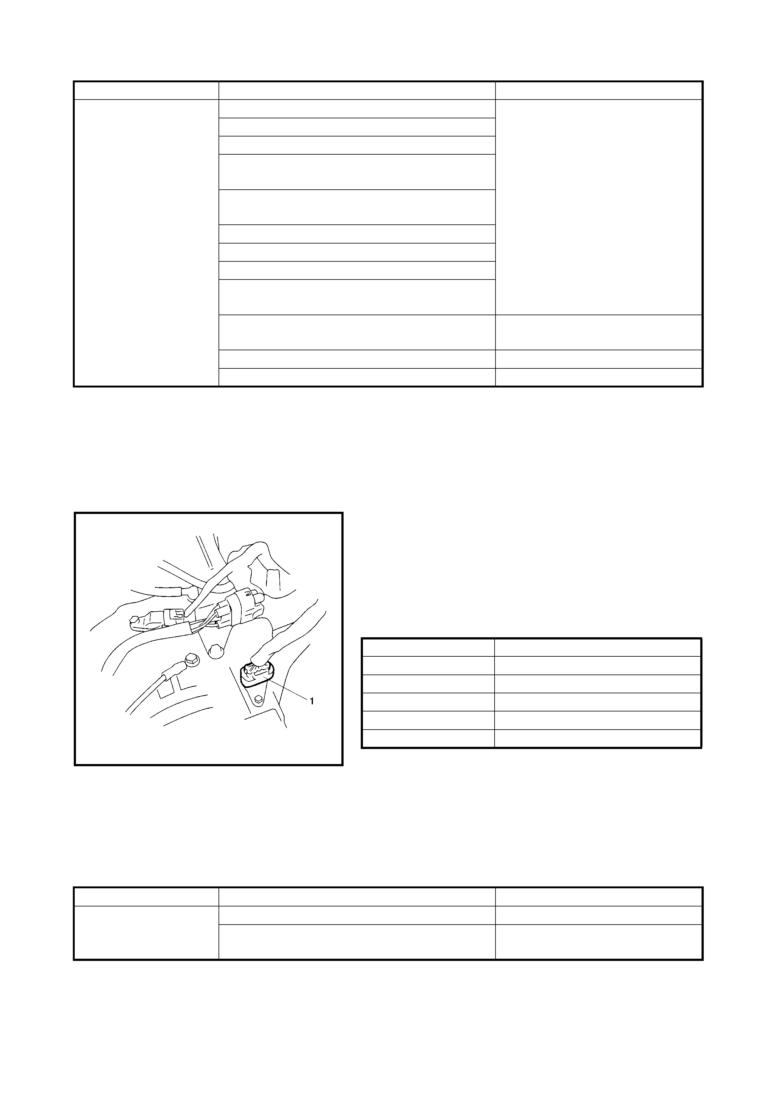
2.14 MANUAL ROAD TEST
This test checks the gears being used in L, 2 or D range
when driven with the gear shift control system not operat-
ing. Test drive the vehicle on a level road.
NOTE: Before this test, check the diagnostic trouble code
(DTC).
1. With select lever in P, start engine and warm it up.
2. After warmi ng up engi ne, turn ignit ion swit ch OFF and
disconnect valve body harness connector (1).
3. With select lever in L range, start the vehicle and check
that 3rd gear is being used, refer to the table below.
Vehicle speed per 1000 rpm in engine speed (V1000
table, reference).
4. With the vehicle running, shift the select lever to 2 range and check that 3rd gear is being used.
5. With the vehicle running, shift the select lever to D range and check that 3rd gear is being used.
6. When the checks are completed, stop the vehicle, turn the ignition switch OFF and connect the valve
body harness connector.
7. Clear the DTC.
TROUBLESHOOTING
TCC (lock-up ) functi on
does not operate Malfunction of TCC solenoid valve Inspect. If NG, replace.
Malfunction of shift solenoid valve-A and/or-B
Malfunction of brake light switch
Malfunction of engine coolant temperature
sensor
Malfunction of output shaft speed sensor
(VSS)
Malfunction of input shaft speed sensor
Malfunction of throttle position sensor
Malfunction of transmission range sensor
Malfunction of transm ission fluid temperature
sensor
Malfunction of pressure control solenoid valve Inspect. If NG, replace valve body
assembly.
Faulty valve body component Replace valve body assembly.
Faulty torque converter Replace.
Condition Possible Cause Correction
Gear position Vehicle speed
1st 8.9 km/h
2nd 16.3 km/h
3rd 25.5 km/h
4th (O/D) 36.6 km/h
Reverse 11.1 km/h
Condition Possible Cause Correct ion
Operated gear is not
correct Faulty valve body component Replace valve body assembly.
Faulty clutch or brake Inspect clutch and brake. If any
parts are faulty, replace them.

2.15 ENGINE BRAKE TEST
WARNING: Before test, ensure that the area behind the vehicle is clear .
1. While driving vehicle in 3rd gear of D range, shift select lever down to 2 range and check that engine
brake operates.
2. As in Step 1, check th e engine bra ke for op eration when the select lever is shifted down to L range and
check that engine brake operates.
3. Engine brake should operate in above test.
TROUBLESHOOTING
2.16 STALL TEST
This test checks the overall performance of the automatic transaxle and the engine by measuring the stall
speed at D and R ranges. Be sure to perform this test only when the transaxle fluid is at normal operating tem-
perature and its level is between FULL and LOW marks.
CAUTION:
• Do not run the engine at stall for more than 5 seconds continuously, or fluid te mperature may rise
excessively.
• After performing the stall test, be sure to leave the engine running at idle for more than 1 minute
before performing another stall test.
1. Apply parking brake and block wheels.
2. Install tach ome ter.
3. Start engine with select lever shifted to P range.
4. Depress the brake pedal fully.
5. Shift th e select lever to D range and depress the accelerator pedal f ully while watching the tachometer.
Note the engine rpm as soon as the rpm becomes constant (stall speed).
6. Release the accelerator pedal immediately after stall speed has been checked.
7. As in Step 6/7, check and note stall speed in R range.
8. Stall speed should be within following specification.
Conditi on Possible Caus e Correctio n
Failure to operate
when shifted down to
2 range
Faulty valve body component Replace valve body assembly.
Faulty O/D and 2nd coast brake Inspect. If NG, replace.
Failure to operate
when shifted down to
L range
Faulty valve body component Replace valve body assembly.
Faulty 1st and reverse brake Inspect. If NG, replace.
ENGINE STALL SPEED STANDARD 2200 - 2600 RPM

TROUBLESHOOTING
2.17 TIME LAG TEST
This test checks the condition of the clutch, brake and fluid pressure. “Time lag” means the time
elapsed since the selector lever is shifted with engine idlin g until shock is felt.
1. With chocks placed in front and behind front and rear wheels, depress the brake pedal.
2. Start the engine.
3. With a stop watch ready, shift the select le ve r from N to D range and mea sure the tim e from tha t mome nt
until shock is felt.
4. As in Step 3, measure the time lag by shifting the select lever from N to R range.
NOTE:
• When repeating this test, be sure to wait at least one minute after the select lever is returned to N range.
• The engine should be fully warmed for this test.
• Repeat the test 3 times and take an average of those times for final time lag data.
Condition Possible Cause Correction
Lower than standard
level in both D and R
range
Engine output torque failure Inspect and repair engine.
Faulty one-way clutch of torque converter Replace torque converter.
Higher than standard
level in D range Malfunction of pressure control solenoid valve
(Low line press ure) Inspect. If NG, replace valve body
assembly.
Faulty valve body component Replace valve body assembly.
Slippery forward clutch Inspect. If NG, replace.
Faulty one-way clutch No.2
Leakage from D range fluid pressure circuit Overhaul or replace valve body
assembly.
Higher than standard
level in R range Malfunction of pressure control solenoid valve
(Low line press ure) Inspect. If NG, replace valve body
assembly.
Faulty valve body component Replace valve body assembly.
Slippery reverse clutch Inspect. If NG, replace.
Slippery 1st and reverse brake
Leakage from R range fluid pressure circuit Overhaul or replace valve body
assembly.
Higher than standard
level in both D and R
range
Malfunction of pressure control solenoid valve
(Low line press ure) Inspect. If NG, replace valve body
assembly.
Faulty valve body component Replace valve body assembly.
Clogged oil strainer Replace.
Faulty oil pump Inspect. If NG, replace.
Leakage from both D and R range fluid pres-
sure ci rcuit Overhaul or replace valve body
assembly.
GEAR SHIFTING TIME LAGN
→
D
N
→
R LESS THAN 0.7 SEC
LESS THAN 1.2 SEC
TROUBLESHOOTING
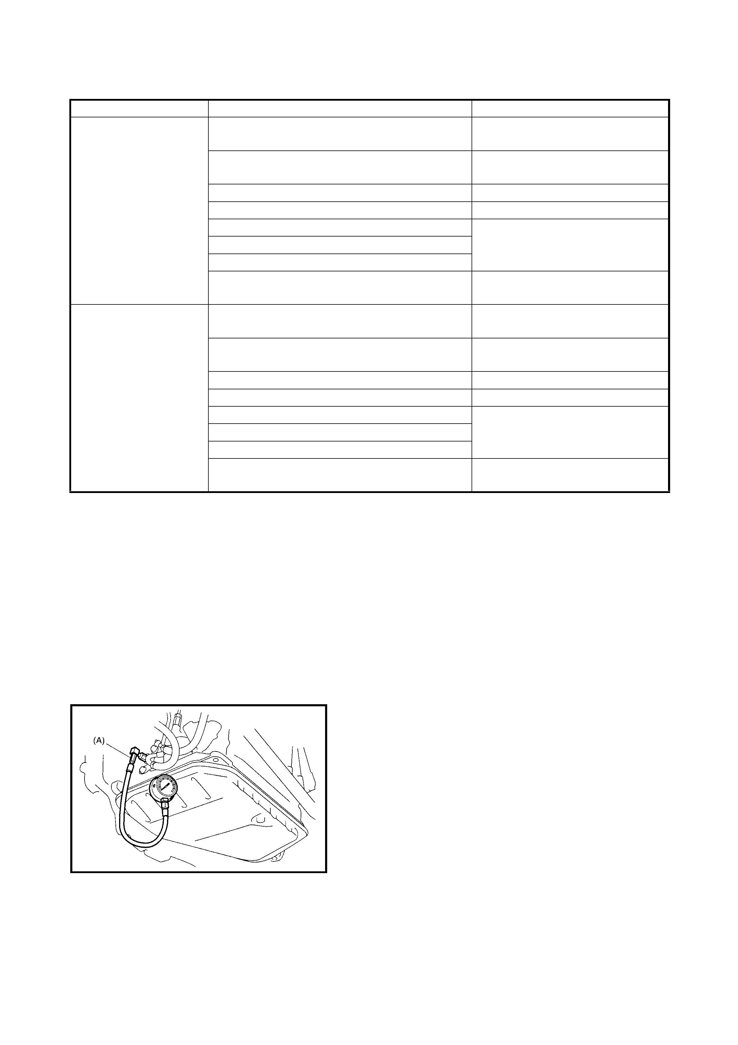
2.18 LINE PRESSURE TEST
The purpose of this test is to check the operating conditions
of each part by measuring the fluid pressure in the fluid
pressure line.
Line pressure test requires the following conditions.
• Automatic fluid is at normal operating temperatu re (70
– 80°C).
• Fluid is replenished to proper level (between FULL and
LOW on dipstick).
• Air conditioner switch is turned OFF.
1. Apply the parking brake securely and place chocks
against wheels.
2. Remove the fluid pressure check hole plug bolt.
3. Attach oil pressure gauge, special tool 09925-37811-
001 (A) to the fluid pressure check hole in the transaxle
case.
CAUTION: After attaching the oil pressure gauge,
check that there are no fluid leaks.
4. Depress the foo t brake fully, run the engin e at idle and
stall then check the fluid pressure in D or R range.
CAUTION:
• Do not run t he engine a t stall speed for mo re t han 5
seconds.
• After performing the line pressure test, leave the
engine running at idle for more than one minute
before performing another line pressure test.
Condition Possible Cause Correction
N → D time lag
exceeds specification Malfunction of transmission fluid temperature
sensor Inspect. If NG, replace.
Malfunction of pressure control solenoid valve
(Low line press ure) Inspect. If NG, replace valve body
assembly.
Faulty valve body component Replace valve body assembly.
Clogged oil strainer Replace.
Faulty oil pump Inspect. If NG, replace.
Faulty forward clutch
Faulty one-way clutch No.2
Leakage from “D” range fluid pressure circuit Overhaul or replace valve body
assembly.
N → R time lag
exceeds specification Malfunction of transmission fluid temperature
sensor Inspect. If NG, replace.
Malfunction of pressure control solenoid valve
(Low line press ure) Inspect. If NG, replace valve body
assembly.
Faulty valve body component Replace valve body assembly.
Clogged oil strainer Replace.
Faulty oil pump Inspect. If NG, replace.
Faulty reverse clutch
Faulty 1st and reverse brake
Leakage from “R” range fluid pressure circuit Overhaul or replace valve body
assembly.

AUTOMATIC TRANSMISSION LINE PRESSURE
TROUBLESHOOTING
2.19 P RANGE TEST
1. Stop the vehicle on a slope of 5 degrees or more, shift the select lever to P range while applying the
parking brake.
2. Stop the engine, depress the brake pedal and release the parking brake.
3. Release the brake pedal gradually and check that the vehicle remains stationary.
4. Depress the brake pedal and shift the select lever to N range.
5. Release the brake pedal gradually and check that the vehicle moves.
WARNING: Before test, make sure that the area around the vehicle is clear.
TROUBLESHOOTING
2.20 DIAGNOSTIC FLOW TABLE A-1: NO GEAR SHIFT TO O/D
SYSTEM DESCRIPTION
TCM does not shift to O/D gear under any of the following conditions.
• O/D off switch is turned ON (O/D OFF lamp lights)
• Engine coolant temperature is less than 50°C
• A/T fluid temperature is less than 20°C
• Input shaft speed sensor or its circuit is faulty (P0715)
• Output shaft speed sensor (VSS) or its circuit is faulty(P0720)
• Engine speed signal circuit is faulty (P0725)
• Pressure control solenoid valve or its circuit is faulty (P0748)
• Engine torque sign al ci rcuit is faul ty (P17 30)
D range R range
At idle speed 3.8 – 4.2 kg/cm
2
6.0 – 7.0 kg/cm
2
At stall speed 10.9 – 12.1 kg/cm
2
16.7 – 19.3 kg/cm
2
Condition Possible Cause Correction
Higher than standard
level in each range Malfunction of pressure control solenoid valve
(Low line press ure) Inspect. If NG, replace valve body
assembly.
Faulty valve body component Replace valve body assembly.
Lower than standard
level in each range Malfunction of pressure control solenoid valve
(Low line press ure) Inspect. If NG, replace valve body
assembly.
Faulty valve body component Replace valve body assembly.
Clogged oil strainer Replace.
Faulty oil pump Inspect. If NG, replace.
Leakage from both “D” and “R” range fluid
pressure circuit Overhaul or replace valve body
assembly.
Lower than standard
level only in D range Leakage from “D” range fluid pressure circuit Overhaul or replace valve body
assembly.
Lower than standard
level only in R range Leakage from “R” range fluid pressure circuit Overhaul or replace valve body
assembly.
Condition Possible Cause Correction
Vehicle moves at P range or remains
stationary at N range Defective parking lock pawl or spring Inspect. If NG, repair.

TROUBLESHOOTING
WARNING:
• When performing a road test, select an area where there is no traffic and exercise extreme
caution.
• The road test should be carried out on a level road with 2 people, a driver and tester.
Step Action Yes No
1
Was 2.4 AUTOMATIC TRANSAXLE
DIAGNOSTIC FLOW TABLE in this section
performed?
Go to Step 2. Go to 2.4 AUTOMATIC
TRANSAXLE
DIAGNOSTIC FLOW
TABLE in this Section.
2
Check DTC.
Is DTC P0715, P0720, P0725, P0748 or
P1730 detected?
Perform DTC Flow table
to repair and retry. Go to Step 3.
3
Perform runni ng test under the following
conditions and measure the voltage
between terminal C44-4 of TCM connector
and ground, terminal C44-3 of TCM connec-
tor and ground .
• O/D off switch is turne d OFF
• Eng ine coolan t tempe rature i s in norm al
operating temperat ure
• Sel ector lever is in D range
• Drive the vehicle in 4th gear condition,
refer to AUTOMATIC GEAR SHIFT
DIAGRAM in 1.5 TCM in this Section.
Do results satisfy the value as follows?
Voltage between terminal C44-4 of TCM
conn ec tor and grou nd: 0 – 1 V
Voltage between terminal C44-3 of TCM
conn ec t or and grou n d: 9 – 14 V
Fau lt y sh i ft sole no id
valve, circuit or tran-
saxle.
BRN circuit shorted to
power circ uit o r open, or
BLK/YEL circuit shorted
to ground. If wire is OK,
go to Step 4.
4
O/D off switch signal inspection.
With ignition switch ON, check voltage
between terminal G99-3 of TCM connector
and ground.
O/D off switch OFF: 8 – 14 V
O/D off switch ON: 0 – 1 V
Substitute a known-
good TCM and recheck. Faulty O/D off switch or
its circ ui t.
If OK, substitute a
known good TCM and
recheck.

2.21 DIAGNOSTIC FLOW TABLE A-2: NO LOCK-UP OCCURS
SYSTEM DESCRIPTION
The TCM turns the TCC solenoid OFF under any of the following conditions:
• Brake light switch is turned ON (Brake pedal is depressed)
• Engine coolant temperature is less than 60°C
• Throttle opening is as much as 0%
• Transmission range sensor or its circuit is faulty (P0705)
• Transmission fluid temperature sensor or its circuit is faulty (P0710)
• Input shaft speed sensor or its circuit is faulty (P0715)
• Output shaft speed sensor (VSS) or its circuit is faulty (P0720)
• TCC (lock-up) solenoid valve or its circuit is faulty (P0743)
• Pressure control solenoid valve or its circuit is faulty (P0748)
• Shift solenoid valve-A or its circuit is faulty (P0753)
• Shift solenoid valve-B or its circuit is faulty (P0758)
• Throttle position signal circuit is faulty (P1700)
TROUBLESHOOTING
WARNING:
• When performing a road test, select an area where there is no traffic and exercise extreme
caution.
• The road test should be carried out on a level road with 2 people, a driver and tester.
Step Action Yes No
1Was 2.4 AUTOMATIC TRANSAXLE
DIAGNOSTIC FLOW TABLE in this Section
performed?
Go to Step 2. Go to 2.4 AUTOMATIC
TRANSAXLE
DIAGNOSTIC FLOW
TABLE in this Section.
2Check DTC.
Is DTC P0705, P0710, P0715, P0720, P0743,
P0748, P0753, P0758 or P1700 detected?
Perform DTC Flow Table
to repair and retry. Go to Step 3.
3• Perform running test under the following
condi tions and c heck vol tage between te r-
minal C44-12 of TCM connector and
ground.
• Engine coolant temperature is in normal
operating temperature.
• O/D OFF switch is turned OFF.
• Selector lever is in D range.
• Brake pedal is released.
• Drive vehicle with 4th gear and TCC ON
condition, refer to AUTOMATIC GEAR
SHIFT DIAGRAM in 1.5 TCM in this Sec-
tion.
Is terminal voltage about 9 – 14 V?
Faulty TCC solenoid
valve, circuit or transaxle. GRN/WHT circuit shorted
to ground. If wire is OK,
go to Step 4.
4Brake light switch signal inspection
With ignition switch ON, check voltage
between terminal C44-16 of TCM connector
and ground.
Brake pedal is released: 0 – 1 V
Brake pedal is depressed: 8 – 14 V
Is result a s sp ecif i ed?
Substitute a known - good
TCM and rech ec k. Mis-adj us ted brak e light
switch, faulty brake light
switch or its circuit.
If OK, substitute a know-
good TCM and recheck.
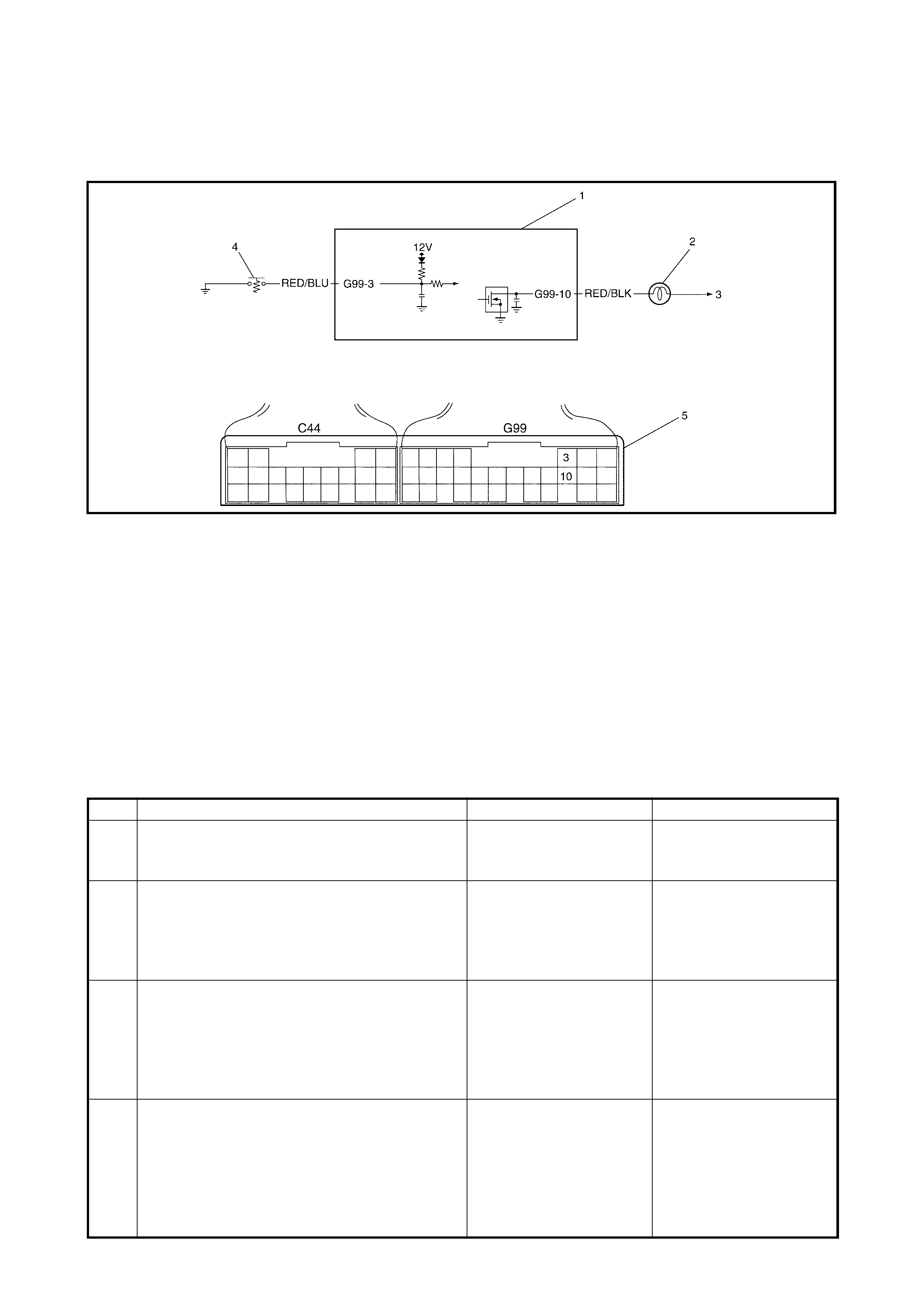
2.22 DIAGNOSTIC FLOW TABLE A-3: O/D OFF LAMP CIRCUIT CHECK
(O/D OFF LAMP LIGHTS STEADILY )
WIRING DIAGRAM
Legend
CIRCUIT DESCRIPTION
Operation (ON/OFF) of the O/D OFF lamp is controlled by the transmission control module (TCM).
When the ignition switch is turned ON and a malfunction is not detected, the TCM turns the O/DOFF lamp ON
for only 2 seconds to check the bulb then turns it OFF.
When the i gnitio n switc h is turne d ON , regardl ess of wether the engi ne is runn ing or not and a malfunc tion is
detected, the O/D OFF lamp is flashed by the TCM while the malfunction is detected. This warns the driver of
a problem.
TROUBLESHOOTING
1. TCM 3. To ignition switch 5. Terminal arrangement of
2. O/D OF” lamp 4. O/D off switch TCM connector
3. To ign iti on swit ch (vie wed fro m harnes s si de)
Step Action Yes No
1 Check O/D off switch status.
Press O/ D OF F swi tc h butt on .
Does O/D OFF lamp light steadily?
Go to Step 2. System is OK
2 Check O/D OFF lamp circuit for short.
Turn ignition switch OFF and disconnect TCM
connectors.
Turn ignition switch ON.
Does O/D OFF lamp light steadily yet?
RED/BLK circuit shorted
to ground. Go to Step 3.
3 Check O/D OFF switch circuit.
Turn ignition switch OFF.
Check continuity between terminal G99-3 of
disconnected harness side connector and
ground.
Is continui ty indicate d?
Go to step 4. Substitute a known-good
TCM and recheck.
4 Check O/D OFF switch for operation.
Disconnect O/D off switch connector.
Check continuity between terminals under
each condition below.(See fig.)
O/D OFF switch is released: No continuity
O/D OFF switch is held in: Continuity
Is check result satisfactory?
RED/BLU circuit shorted
to ground. Replace O/D off switch.
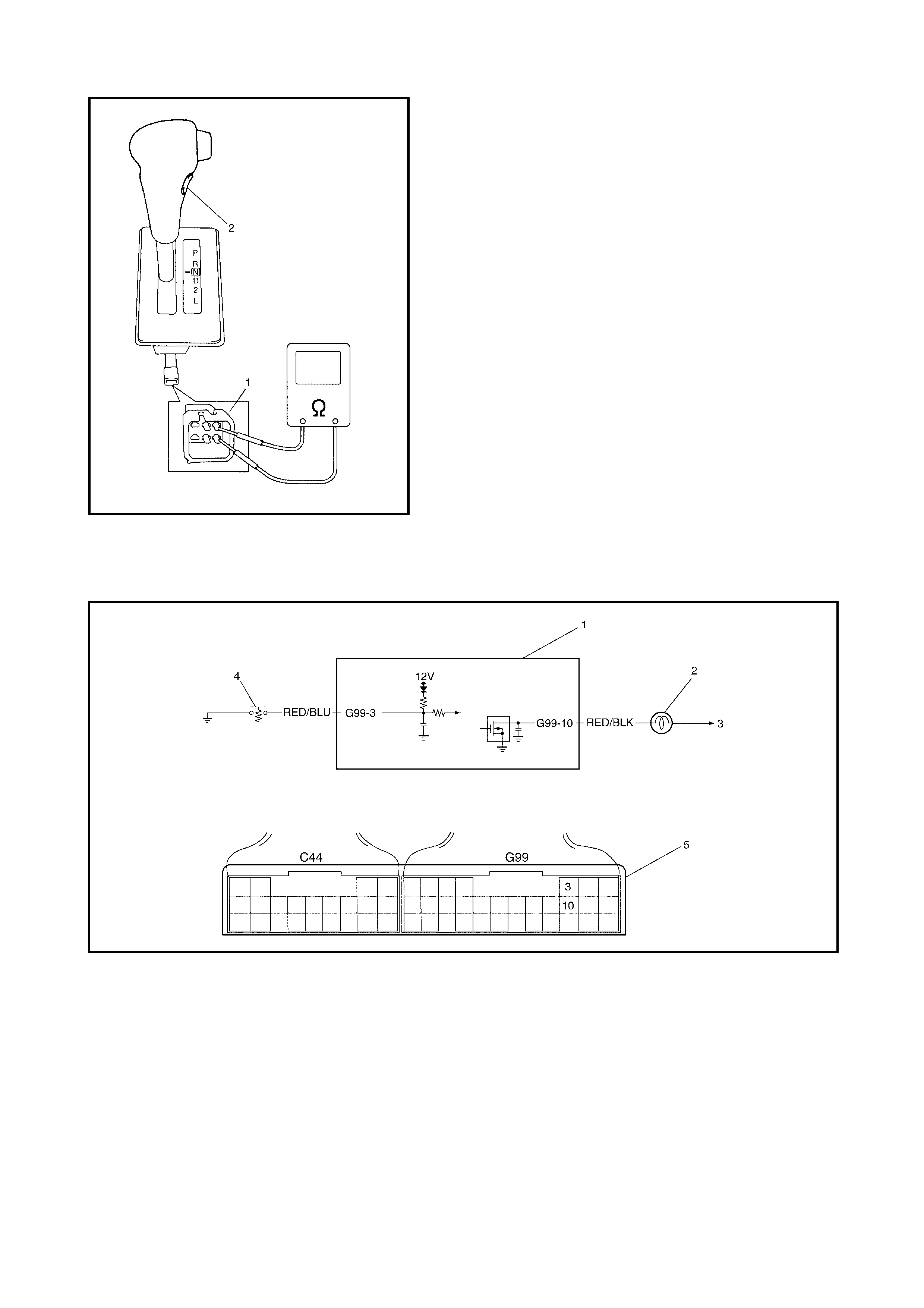
Figure for Ste p 2 and Step 4 showing O/D OFF switch con-
nector (1).
2.23 DIAGNOSTIC FLOW TABLE A-4: O/D OFF LAMP CIRCUIT CHE CK
(O/D OFF LAMP DOES NOT LIGHT AT ALL)
WIRING DIAGRAM
Legend
1. TCM 3. To ignition switch 5. Terminal arrangement of
TCM connector
(viewed from harness side)
2. “O/D OFF” lamp 4. O/D off switch
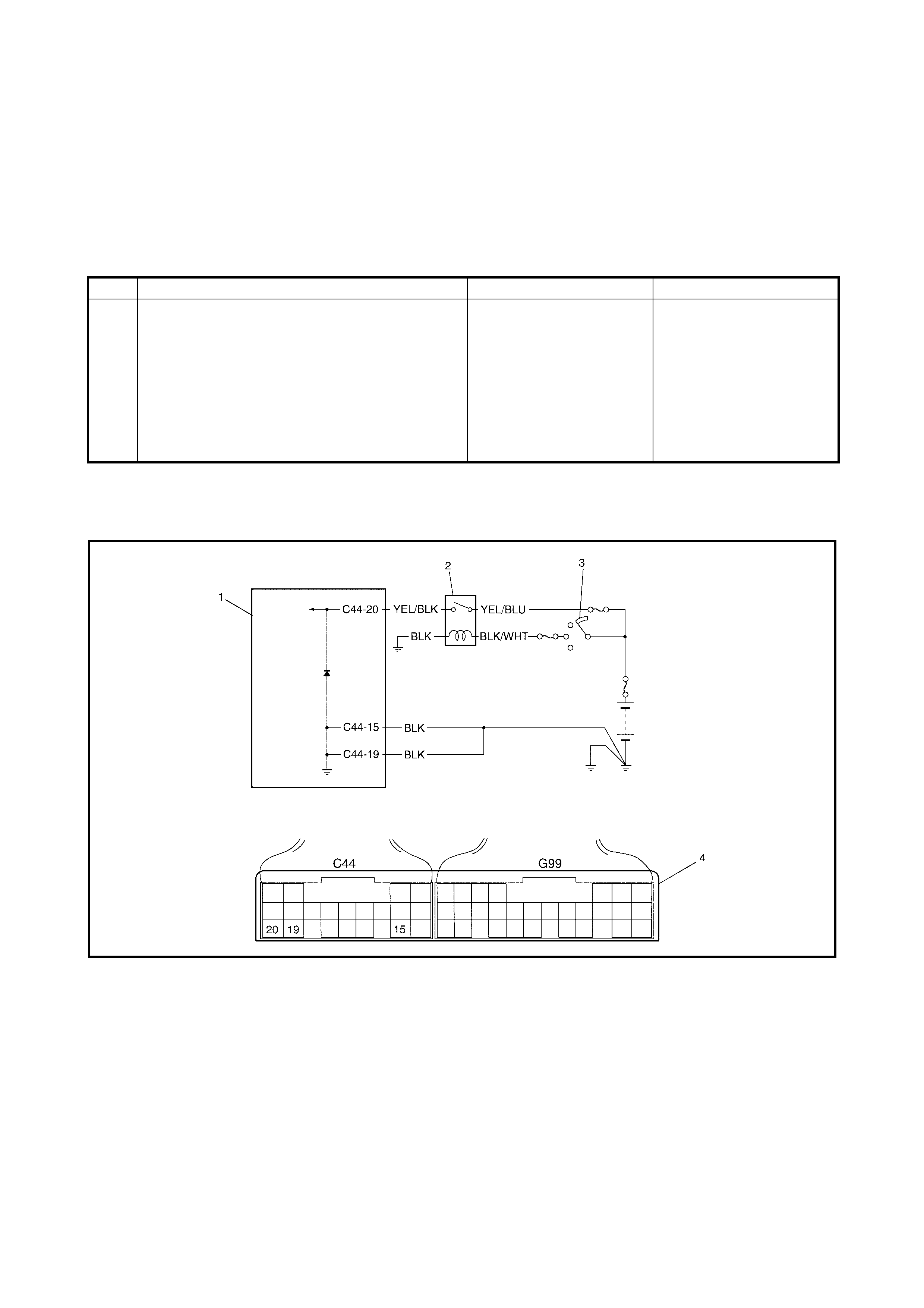
CIRCUIT DESCRIPTION
The operation (ON/OFF) of the O/D OFF lamp is controlled by the transmission control module (TCM).
When the ignition switch is turned ON and a malfunction is not detected, the TCM turns the O/D OFF lamp ON
for only 2 seconds to check bulb then turns it OFF.
When the ig nition switch in turned ON , regardl ess of wether the engine is run ning or not and a mal functi on is
detected, the O/D OFF lamp is flashed by the TCM while the malfunction is detected. This warns the driver of
a problem.
TROUBLESHOOTING
2.24 DIAGNOSTIC FLOW TABLE A-5: TCM POWER AND GR OU ND CIRCUIT CHECK
WIRING DIAGRAM
Legend
Step Action Yes No
1Check O/D OFF lamp circuit.
Turn ignition switch OFF and disconnect TCM
connectors.
Using service wire, connect terminal G99-10 of
disconnected harness side TCM connector
and ground.
Turn ignition switch ON.
Does O/D OFF lamp light?
Poor terminal G99-10
connection.
If OK, substitute a known-
good TCM and recheck.
RED/BLK circuit open or
bulb burned out.
1. TCM 3. Ignition switch 4. Terminal arrangement of
TCM connector
(viewed from harness side)
2. A/T relay
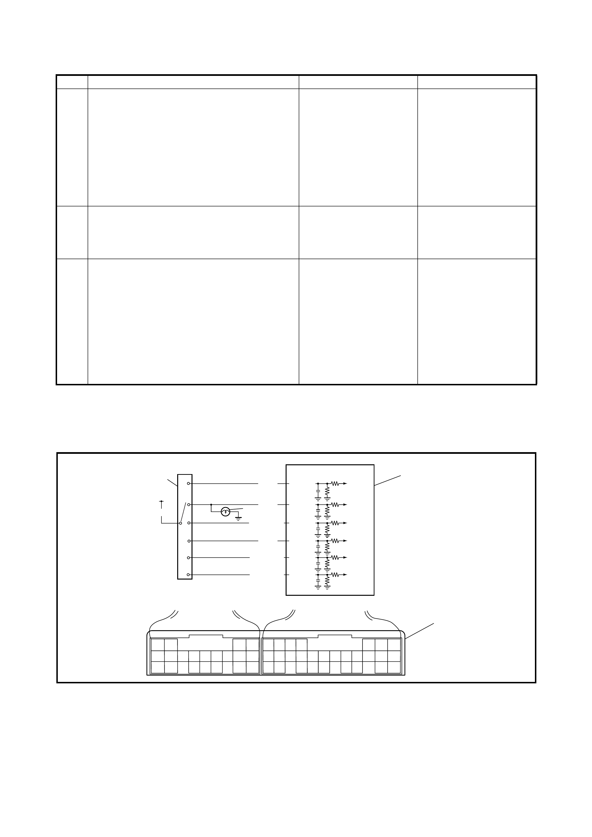
TROUBLESHOOTING
2.25 DTC P0705/DTC NO.34 TRANSMISS ION RA NGE SENSOR
CIRCUIT MALFUNCTION
WIRING DIAGRAM
Legend
Step Action Yes No
1 Check TCM Power Circuit.
Disconnect TCM connector with ignition switch
OFF.
Check for proper connection to TCM at C44-20
terminal.
If OK, turn ignition switch ON and check volt-
age at terminal C44-20 of disconnected TCM
connector.
Is it 10 – 14 V?
Go to Step 3. Go to Step 2.
2 Check A/T Relay Operation.
Check A/T relay operation, refer to 3.13 A/T
RELAY, INSPECTION in this Section.
Is check result satisfactory?
YEL/BLK, YEL/BLU.
BLK/W HT or BLK circuit
for power supply open.
Replace A/T relay.
3
Check TCM Ground Circuit.
1) Turn igniti on switch OFF.
2) With TCM connectors disconnected,
check for proper c onnection to TCM at
C44-15/C44-19 terminal.
3) If OK, check resistance between C44-
15/C44-19 terminal of disconnected
TCM connector and body ground.
Is continuity indicated?
TCM power and ground
circuits are in good con-
dition.
BLK circuit for TCM
ground open.
98
21 20
21
C44 G99
2P
R
N
D
2
L
3
ORN
RED
GRN
GRN/ORN
GRN/YEL
IG11
RED/BLK
BLU/WHT
G99-2
G99-1
G99-9
G99-8
G99-21
G99-20
4
1
1. TCM 3. Backup lamp 4. T erminal arrangement of TCM
connector (viewed from har-
ness side)
2. Transmission range sensor

DTC DETECTING CONDITION AND TROUBLE AREA
DTC CONFIRMATION PROCEDURE
WARNING:
• When performing a road test, select an area where there is no traffic and exercise extreme
caution.
• The road test should be carried out on a level road with 2 people, a driver and tester.
1. Connect Tech 2 to the DLC with the ignition switch OFF.
2. Clear the DTC in the TCM memory and start the engine.
3. Shift the selector lever to each of L, 2, D, N, R and P ranges for 20 seconds each.
4. Start the vehicle and increase the vehicle speed to about 40 km/h in D range.
5. Keep driving at about 40 km/h vehicle speed for 40 seconds.
6. Release the accelerator pedal, decrease the vehicle speed and stop the vehicle.
7. Check the DTC.
TROUBLESHOOTING
DTC DETECTING CONDITION TROUBLE AREA
• Transmission range switch signal (P, R, N, D, 2, or L)
is not inputted for more than 32 seconds when vehicle
speed is faster than 30 km/h and engine speed is
faster than 1500 rpm.
or
• Two or more signals are inputted simultaneously for
12 seconds.
• Transmission range sensor (switch) malad-
justed.
• T ransmission range sensor (switch) or its circuit
malfunction.
•TCM
Step Action Yes No
1Was 2.4 AUTOMATIC TRANSAXLE
DIAGNOSTIC FLOW TABLE performed? Go to Step 2. Go to 2.4 AUTOMATIC
TRANSAXLE
DIAGNOSTIC FLOW
TABLE in this Section.
2Do you have Tech 2? Go to Step 3. Go to Step 4.
3Check Transmission range sensor(switch) cir-
cuit for operation.
Check by using Tech 2:
Connect Tech 2 to DLC with ignition switch
OFF.
Turn ignition switch ON and check transmis-
sion range signal (P, R, N, D, 2 or L) on display
when shifting select lever to each range.
Is applicable range indicated?
Are check results satisfactory?
Intermittent trouble.
Check for intermittent
refer to Section 0A,
1.7 ELECTRICA L
CIRCUIT INSPECTION
PROCEDURE,
INTERMITTENT AND
POOR CONNECTION.
Go to Step 5.
4Check Transmission range sensor(switch) cir-
cuit for operation.
Check by not using Tech 2:
Turn ignition switch ON.
Check voltage at terminals G99-1, G99-2,
G99-8, G99-9, G99-20 and G99-21 respec-
tively with select lever shifted to each range.
Taking terminal G99-21 as an example, is bat-
tery voltage indicated only when select lever is
shifted to 2 range and 0 V for other ranges as
shown in table below?
Chec k voltag e at othe r terminal s likewis e, ref er
to the figure.
Are check results satisfactory?
Intermittent trouble.
Check for intermittent
refer to Section 0A,
1.7 ELECTRICA L
CIRCUIT INSPECTION
PROCEDURE,
INTERMITTENT AND
POOR CONNECTION.
Go to Step 5.
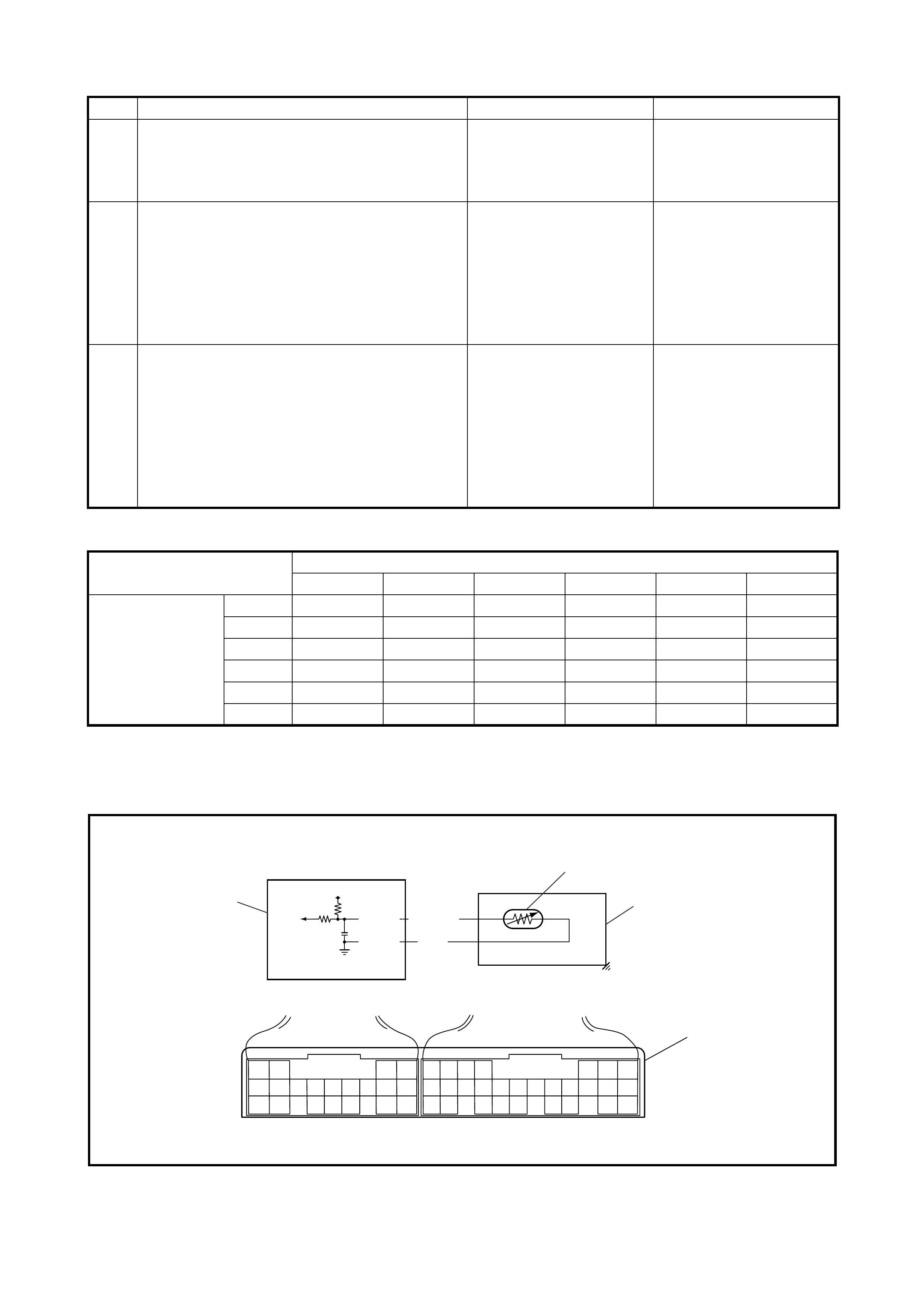
Table for Step 4
2.26 DTC P0710/DTC NO.36 OR 38 TRANSMISSION FLUID TEMPERATURE
SENSOR CIRCUIT MALFUNCTION
WIRING DIAGRAM
Legend
5Check select cable for adjustment, refer to
3.3 SELECT CABLE, ADJUSTMENT in this
Section.
Is it adjusted correctly?
Go to Step 6. Adjust.
6Check transmission range sensor for installa-
tion position.
Shift select lever to N range.
Check that N reference line on sensor and
needle direction shaped on lock washer are
aligned.
Are they aligned?
Go to Step 7. Adjust.
7Check Transmission range sensor (switch),
refer to 3.4 TRANSMISSION RANGE
SENSOR (SHIFT SWITCH) in this Section.
Are check results satisfactory?
RED/BLK, ORN, RED,
GRN/ORN, GRN, GRN/
YEL or BLU/WHT circuit
open or short.
If wires and connections
are OK, substitute a
know-good TCM and
recheck.
Replace Transmission
range sensor.
Step Action Yes No
Terminal
G99-2 G99-1 G99-9 G99-8 G99-21 G99-20
Select lever
position P8 – 14 V0 V0 V0 V0 V0 V
R0 V8 – 14 V0 V0 V0 V0 V
N 0 V 0 V 8 – 14 V 0 V 0 V 0 V
D 0 V 0 V 0 V 8 – 14 V 0 V 0 V
2 0 V 0 V 0 V 0 V 8 – 14 V 0 V
L0 V0 V0 V0 V0 V8 – 14 V
5
14
C44 G99
5V
GRN
C44-5
C44-14
BLU/RED
2
3
4
1
1. TCM 3. A/T 5. Terminal arrangement of TCM
connector (viewed from
harness side)
2. Transmission fluid tempera-
ture sensor 4. Valve body connector

DTC DETECTING CONDITION AND TROUBLE AREA
DTC CONFIRMATION PROCEDURE
WARNING:
• When performing a road test, select an area where there is no traffic and exercise extreme caution.
• The road test should be carried out on a level road with 2 people, a driver and tester.
1. Connect Tech 2 to the DLC with the ignition switch OFF.
2. Clear the DTC in the TCM memory and start the engine.
3. Shift the selector lever to D range and drive the vehicle for about 20 minutes.
4. Stop the vehicle and check the DTC.
TROUBLESHOOTING
DTC DETECTING CONDITION TROUBLE AREA
• Transmission temperature sensor terminal voltage is
less than 0.05 V for 5 minutes or more after turning
ignition switch ON.
or
• Transmission temperature sensor terminal voltage is
more than 4.6 V and shift range is in R, D, 2 or L for 15
minutes after starting engine.
• Transmission fluid temperature sensor or its cir-
cuit malfunction.
•TCM
Step Action Yes No
1Was 2.4 AUTOMATIC TRANSAXLE
DIAGNOSTIC FLOW TABLE performed? Go to Step 2. Go to 2.4 AUTOMATIC
TRANSAXLE
DIAGNOSTIC FLOW
TABLE in this Section.
2Check Transmission Fluid Temperature Circuit
for Open.
1. Turn ignition switch OFF.
2. Disconnect TCM connectors from TCM.
3. Check for proper connect ion to tr ansmis -
sion fluid temperature sensor at terminals
C44-5 and C44-14.
If OK, check continuity between terminals C44-
5 and C44-14 of disconnected harness side
TCM connec to r.
Is continuity indicated?
Go to Step 3. BLU/RED or GRN circuit
open.
3Check Transmission Fluid Temperature Circuit
for Ground Short.
Check continuity between terminal C44-5 of
disconnected harness side TCM connector
and ground.
Is continuity indicated?
BLU/RED circuit shorted
to ground. Go to Step 4.
4Check Transmission Fluid Temperature Circuit
for IG Short.
1. Cool down A/T fluid temperature under
ambient temperature.
2. Connect TCM connectors to TCM with
ignition swi tch OF F.
3. Turn ignition switch ON.
4. Measure voltage between terminal C44-5
of TCM connector and ground.
Is it 4.6 V or more?
BLU/RED circuit shorted
to power circuit.
If circuit is OK, go to
Step 5.
Intermittent trouble or
faulty TCM.
Check for intermittent,
refer to Section 0A,
1.7 ELECTRICAL
CIRCUIT INSPECTION
PROCEDURE.
INTERMITTENT AND
POOR CONNECTION.
If OK, substitute a known-
good TCM and recheck.
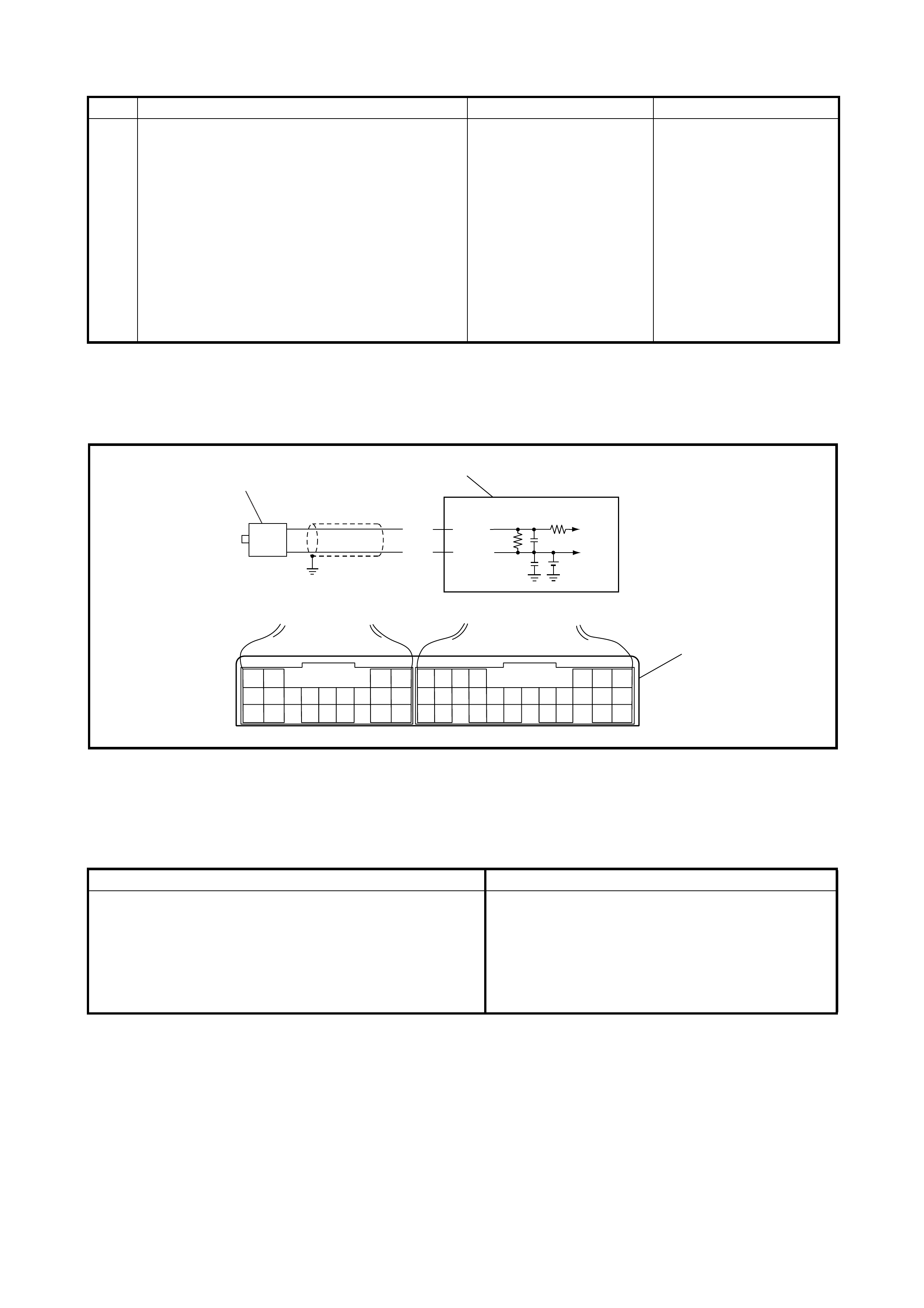
2.27 DTC P0715/DTC NO.14 INPUT/TURBINE SPEED
SENSOR CIRCUIT MALFUNCTION
WIRING DIAGRAM
Legend
DTC DETECTING CONDITION AND TROUBLE AREA
DTC CONFIRMATION PROCEDURE
WARNING:
• When performing a road test, select an area where there is no traffic and exercise extreme caution.
• The road test should be carried out on a level road with 2 people, a driver and tester.
1. Connect Tech 2 to the DLC with the ignition switch OFF.
2. Clear the DTC in the TCM memory and start the engine.
3. Shift the selector lever to D range and drive vehicle at 50 km/h or more in 3rd gear for at least 5 minutes.
4. Stop the vehicle and check the DTC.
5Inspect Transmission Flu id Tem pera t ure
Sensor.
Inspect transmission temperature sensor refer-
ring to 3.14 TRANSMISSION FLUID
TEMPERATURE SENSOR, INSPECTION in
this Section.
Is result satisfactory?
Intermittent trouble or
faulty TCM.
Check for intermittent,
refer to Section 0A,
1.7 ELECTRICA L
CIRCUIT INSPECTION
PROCEDURE.
INTERMITTENT AND
POOR CONNECTION.
If OK, substitute a known-
good TCM and recheck.
Replace transmission
fluid temperature sensor.
Step Action Yes No
17
5
C44 G99
G99-5
2.5V
WHT
BLK G99-17
1
2
3
1. TCM 2. Input shaft speed sensor 3. Terminal arrangement of TCM connector
(viewed from harness side)
DTC DETECTING CONDITION TROUBLE AREA
No input shaft speed sensor signal is detected although
output shaft speed sensor signals are detected. • Input shaft speed sensor or its circuit malfunc-
tion.
• Improper input shaft speed sensor installation.
• Damaged direct clutch drum.
• Foreign material attached to sensor or drum.
•TCM
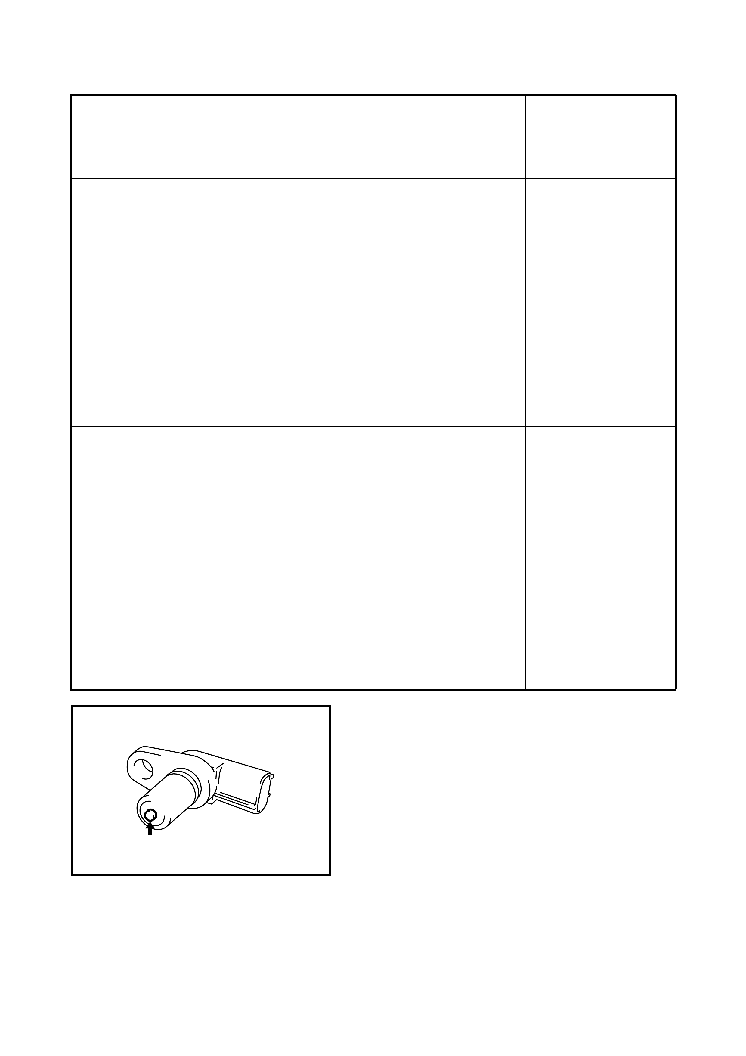
TROUBLESHOOTING
Figure for Step 4
Step Action Yes No
1Was 2.4 AUTOMATIC TRANSAXLE
DIAGNOSTIC FLOW TABLE p erformed? Go to Step 2. Go to 2.4 AUTOMATIC
TRANSAXLE
DIAGNOSTIC FLOW
TABLE in this Section.
2
Check Input Shaft Speed Sensor Circuit.
1. Disconnect TCM connectors with ignition
switch OFF.
2. Check for proper connection to input
shaft speed sensor at G99-5 and G99-17
terminals.
3. If OK, check r esistanc e of sensor circuit.
Resistance between terminals G99-5
and G99-17 of disconnected harness
side TCM connector: 560 – 680 Ω at
20°C (68°F)
Continui ty between t erminal G99-5 /G99-
17 of disconnected harness side TCM
connector and ground: No continuity
Are check result satisf actory?
Go to Step 4. Go to Step 3.
3Inspect Input Shaft Speed Sensor.
Inspect input shaft speed sensor, refer to
3.6 INPUT SHAFT SPEED SENSOR,
INSPECTION in this Section.
Is result satisfac tory ?
WHT or BLK circuit open
or short. Replace input shaft
speed sensor.
4Check visually input shaft speed sensor and
direct clutch drum for the followings. See Fig.
No damage
No foreign material attached
Correct installation
Are they in good condition?
Intermittent trouble or
faulty TCM.
Check for intermittent,
refer to Section 0A,
1.7 ELECTRICAL
CIRCUIT INSPECTION
PROCEDURE.
INTERMITTENT AND
POOR CONNECTION.
If OK, substitute a known-
good TCM and recheck.
Clean, repair or replace.
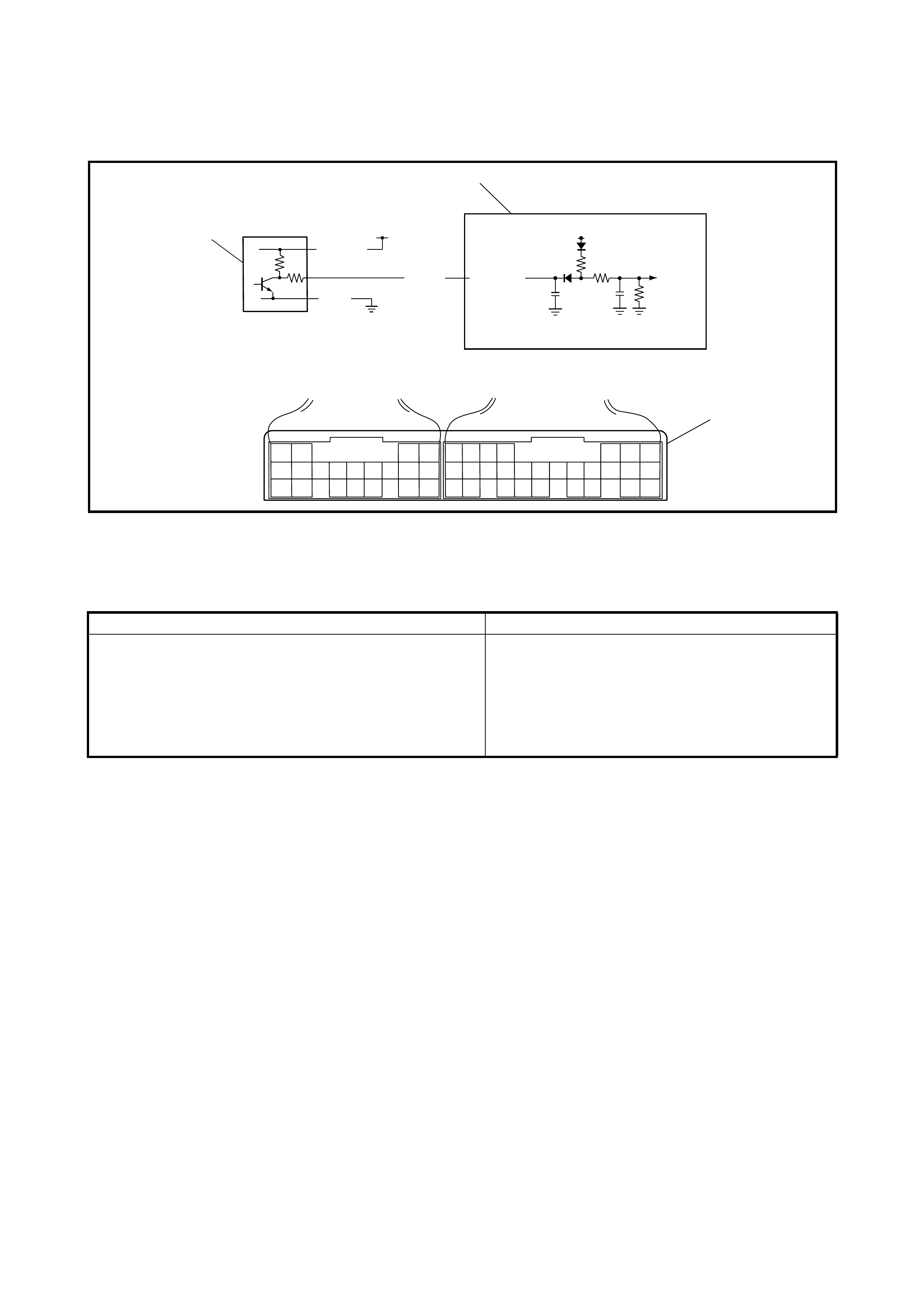
2.28 DTC P0720/DTC NO.31 OUTPUT SPEED SENSOR (VSS) CIRCUIT MALFUNCTION
WIRING DIAGRAM
Legend
DTC DETECTING CONDITION AND TROUBLE AREA
DTC CONFIRMATION PROCEDURE
WARNING:
• When performing a road test, select an area where there is no traffic and exercise extreme caution.
• The road test should be carried out on a level road with 2 people, a driver and tester.
1. Connect Tech 2 to the DLC with the ignition switch OFF.
2. Clear the DTC in the TCM memory and start the engine.
3. Shift the selector lever to D range and drive the vehicle at 5 0 km/h or more ve hicle speed for a t least 3
minutes.
4. Stop the vehicle check the DTC.
24
C44 G99
IG1 12V
YEL G99-24
1
2
3
YEL/BLK
BLK
1. TCM 2. Output shaft speed sensor (VSS) 3. Terminal arrangement of TCM con-
nector (viewed from harness side)
DTC DETECTING CONDITION T ROUBLE AREA
No output shaft speed sensor signal is detected although
input shaft speed sensor signals are detected while vehi-
cle is running at 5 km/h (3 mile/h) or more vehicle speed
with D, 2 or L range.
• Output shaft speed sensor or its circuit mal-
function.
• Damaged sensor gear (driven gear).
• Damaged output shaft speed sensor (VSS)
drive gea r.
•TCM

TROUBLESHOOTING
Step Action Yes No
1Was 2.4 AUTOMATIC TRANSAXLE
DIAGNOSTIC FLOW TABLE in this Section
performed?
Go to Step 2. Go to 2.4 AUTOMATIC
TRANSAXLE
DIAGNOSTIC FLOW
TABLE in this Section.
2 Check Output Shaft Spe ed Sensor (VSS )
Power Circuit.
1. Tur n ign ition swi tc h OFF.
2. Disconnect output shaft speed sensor
connector.
3. Tur n ign ition swi tc h ON.
4. Measur e voltage between YEL/B LK wire
terminal of disconnected output shaft
speed sensor harness side connector
and ground.
Is it 10 – 14 V?
Go to Step 3. YEL/BLK wir e open or
shorted to ground.
3 Check Output Shaft Spe ed Sensor (VSS )
Ground Circuit.
1. Tur n ign ition swi tc h OFF.
2. Check continuity between BLK wire
terminal of disconnected output shaft
speed sensor harness side connector
and ground.
Is continuity indicated?
Go to Step 4. BLK wire open.
4
Check Output Shaft Speed Sensor (VSS)
Signal Circuit for short.
1) Disconnect TCM connectors.
2) Check continuity between YEL wire ter-
minal of disconnected output shaft
speed sens or harness side connector
and ground.
Is continuity indicated?
YEL wire shorted to
ground. Go to Step 5.

5
Check Output Shaft Speed Sensor (VSS)
Signal Circuit for open.
1) Check continuity between YEL wire ter-
minal of disconnected output shaft
speed sens or harness side connector
and terminal G99-24 of disconnected
harness side TCM connector.
Is continuity indicated?
Go to Step 6. YEL wire open.
6
Ins pect Output Shaft Speed Sensor (VSS).
Ins pect output shaft speed sensor, refe r to
3.5 OUTPUT SHA FT SPEED SENSOR,
INSPECTION in thi s Sect io n.
Is check result satisfactory?
Go to Step 7. Replace output shaft
speed sensor.
7 Check Output Shaft Spe ed Sensor (VSS )
Gears Visually.
Check output shaft speed sensor gears for the
followings.
• No damage in drive gear on differential
case
• No damage in driven gear in output shaft
speed sensor
Is result satisfactory?
Inte rmittent trouble or
Faulty TCM.
Chec k fo r inte rm i tte nt
refer to Section 0A,
1.7 ELECTRICAL
CIRCUIT INSPECTION
PROCEDURE.
INTERMITTENT AND
POOR CONNECTION
.
If OK, substitute a
known-good TCM and
recheck.
Replace drive gear and/
or driven gea r of output
shaft speed sensor.
Step Action Yes No
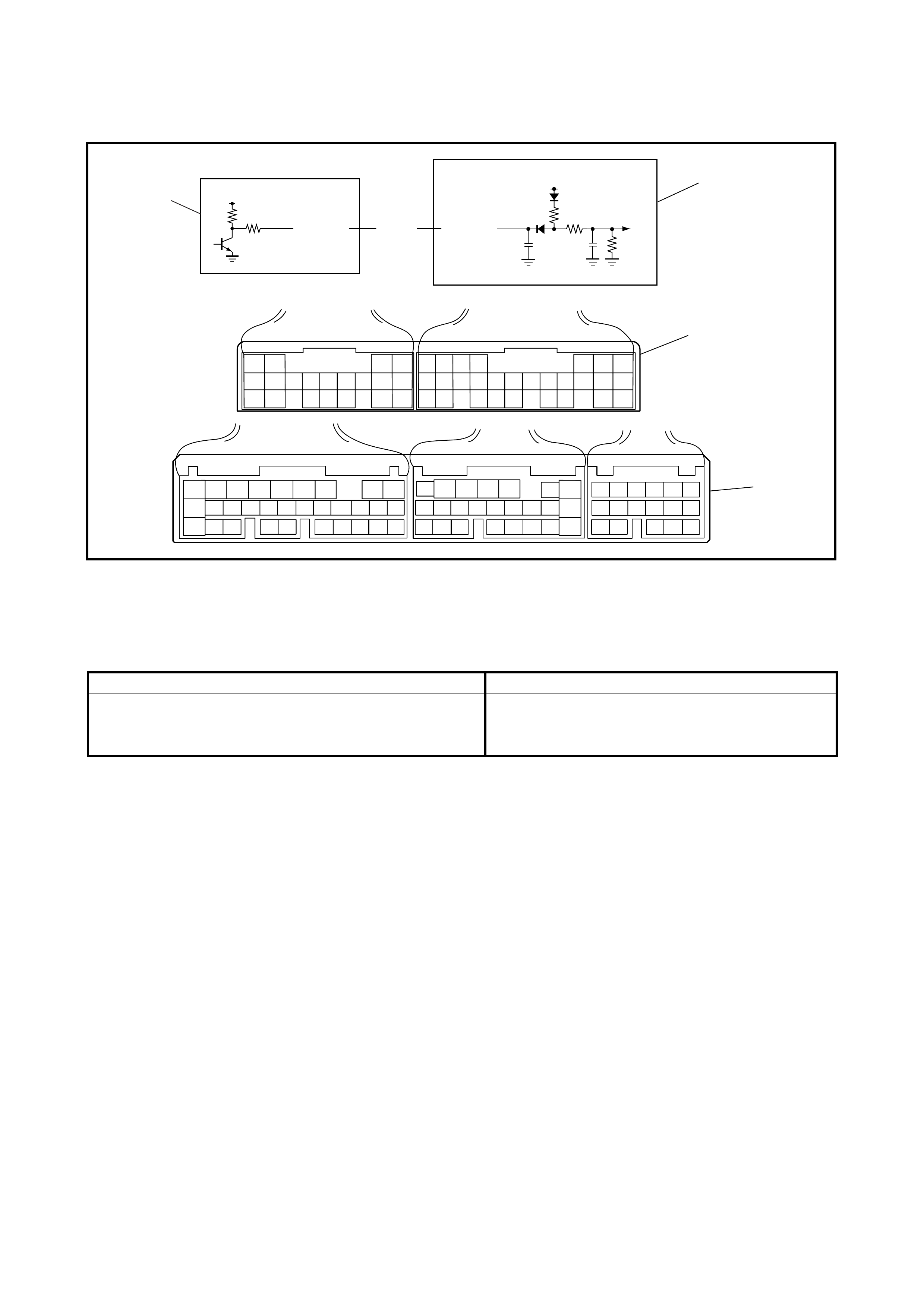
2.29 DTC P0725/DTC NO.35 ENGINE SPEED INPUT CIRCUIT MALFUNCTION
WIRING DIAGRAM
Legend
DTC DETECTING CONDITION AND TROUBLE AREA
DTC CONFIRMATION PROCEDURE
1. Connect Tech 2 to the DLC with the ignition switch OFF.
2. Clear the DTC in the TCM memory.
3. Start the engine and raise the engine speed to 2500 rpm.
4. Maintain engine speed of 2500 rpm for 10 seconds.
5. Release the accelerator pedal and check the DTC.
15
C44 G99
12V 12V
BRN
G02-16 G99-15
2
3
4
C42 C41 G02
16
1
1. TCM 3. Terminal arrangement of TCM
connector (viewed from harness side) 4. Terminal arrangement of ECM
connector (viewed from harness side)
2. ECM
DTC DETECTING CONDITION T ROUBLE AREA
No engine speed signal is inputted although input shaft
speed sensor signals are detected for 5 seconds. • Engine speed input signal circuit malfunction.
•TCM
•ECM

TROUBLESHOOTING
Step Action Yes No
1Was 2.4 AUTOMATIC TRANSAXLE
DIAGNOSTIC FLOW TABLE performed? Go to Step 2. Go to 2.4 AUTOMATIC
TRANSAXLE
DIAGNOSTIC FLOW
TABLE in this Section.
2
Check Engi ne S peed Input Si gnal Circuit for
Open.
1) Turn ig nition switch OFF.
2) Disconnect TCM and ECM connectors
from TCM and ECM.
3) Check for proper connection to TCM at
termin al G99-1 5 an d t o EC M at t er mi nal
G02-16.
4) If OK, check continuity between termi-
nals G99-15 and G02-16 of discon-
necte d harness side TCM and ECM
connectors.
Is continuity indicated?
Go to Step 3. BRN circuit open.
3
Check Engi ne S peed Input Si gnal Circuit for
Short.
1) Check continuity between terminal G99-
15 of disconnected harness side TCM
connector a nd ground.
Is continuity indicated?
BRN circu it sho r te d to
ground. Go to Step 4.
4
Check TCM Terminal Voltage.
1) Connect TCM connectors to TCM with
ignition switch OFF.
2) Turn ignition switch ON.
3) Measure voltage between terminal G99-
15 of connected harness side ECM con-
nector and ground.
Is it 8 – 14 V?
Go to Step 5. Substitute a known-
good TC M and recheck.
5
Check ECM Terminal Volt age.
1) Turn ig nition switch OFF.
2) Connect ECM connectors to ECM.
3) Turn ignition switch ON.
4) Measure voltage between terminal G02-
16 of connected harness side ECM con-
nector and ground.
Is it 0 – 1 V?
Interm it te nt tro u bl e or
faulty TCM or ECM.
Check for intermittent,
refer to Section 0A,
1.7 ELECTRICAL
CIRCUIT INSPECTION
PROCEDURE.
INTERMITTENT AND
POOR CONNECTION.
If OK, substitute a
known-good TCM and/
or ECM recheck.
Substitute a known-
good ECM and recheck.
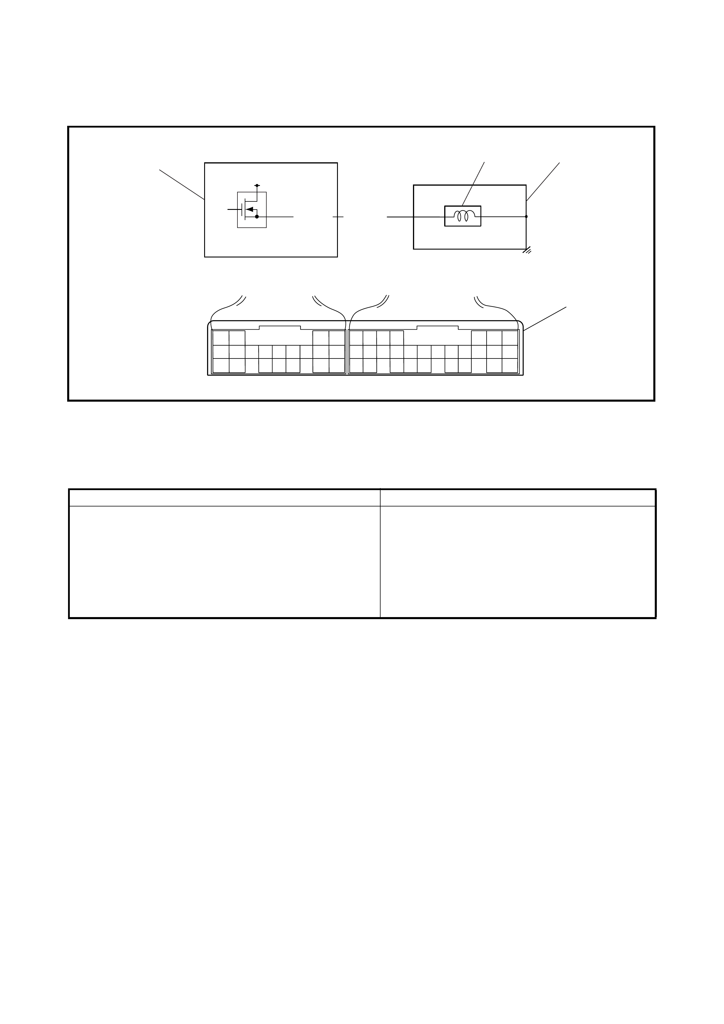
2.30 DTC P0743/DTC NO.25 OR NO.26 TCC SYSTEM ELECTRICAL
WIRING DIAGRAM
Legend
DTC DETECTING CONDITION AND TROUBLE AREA
DTC CONFIRMATION PROCEDURE
WARNING:
• When performing a road test, select an area where there is no traffic and exercise extreme caution.
• The road test should be carried out on a level road with 2 people, a driver and tester.
1. Connect Tech 2 to the DLC with the ignition switch OFF.
2. Clear the DTC in the TCM memory.
3. Start the engine and warm it up to normal operating temperature.
4. Drive the vehicle in D range and repeat lock-up ON and OFF operations 4 times each, refer to the
AUTOMATIC GEAR SHIFT DIAGRAM in 1.5 TC M in th is S ECTIO N. (I n brie f, at 75 k m /h i n 4t h ge ar, th e
accelerator pedal is depressed so that the throttle opens 10% or less and is then released, repeating 4
times).
5. Decrease the vehicle speed gradually and stop the vehicle.
6. Check the DTC.
12
C44 G99
12V
C44-12 WHT/BLU
3
2
4
1
1. TCM 3. A/T 4. Terminal arrangement of TCM connector
(viewed from harness side)
2. TCC solenoid valve
DTC DETECTING CONDITION TROUBLE AREA
• Voltage of TCC solenoid valve TCM terminal is low
although TCM is commanding TCC solenoid to turn
ON.
or
• Voltage of TCC solenoid valve TCM terminal is high
although TCM is commanding TCC solenoid to turn
OFF.
• TCC solenoid valve circuit shorted to ground.
• TCC solenoid valve circuit open or shorted to
power circuit.
• TCC solenoid valve malfunction.
•TCM
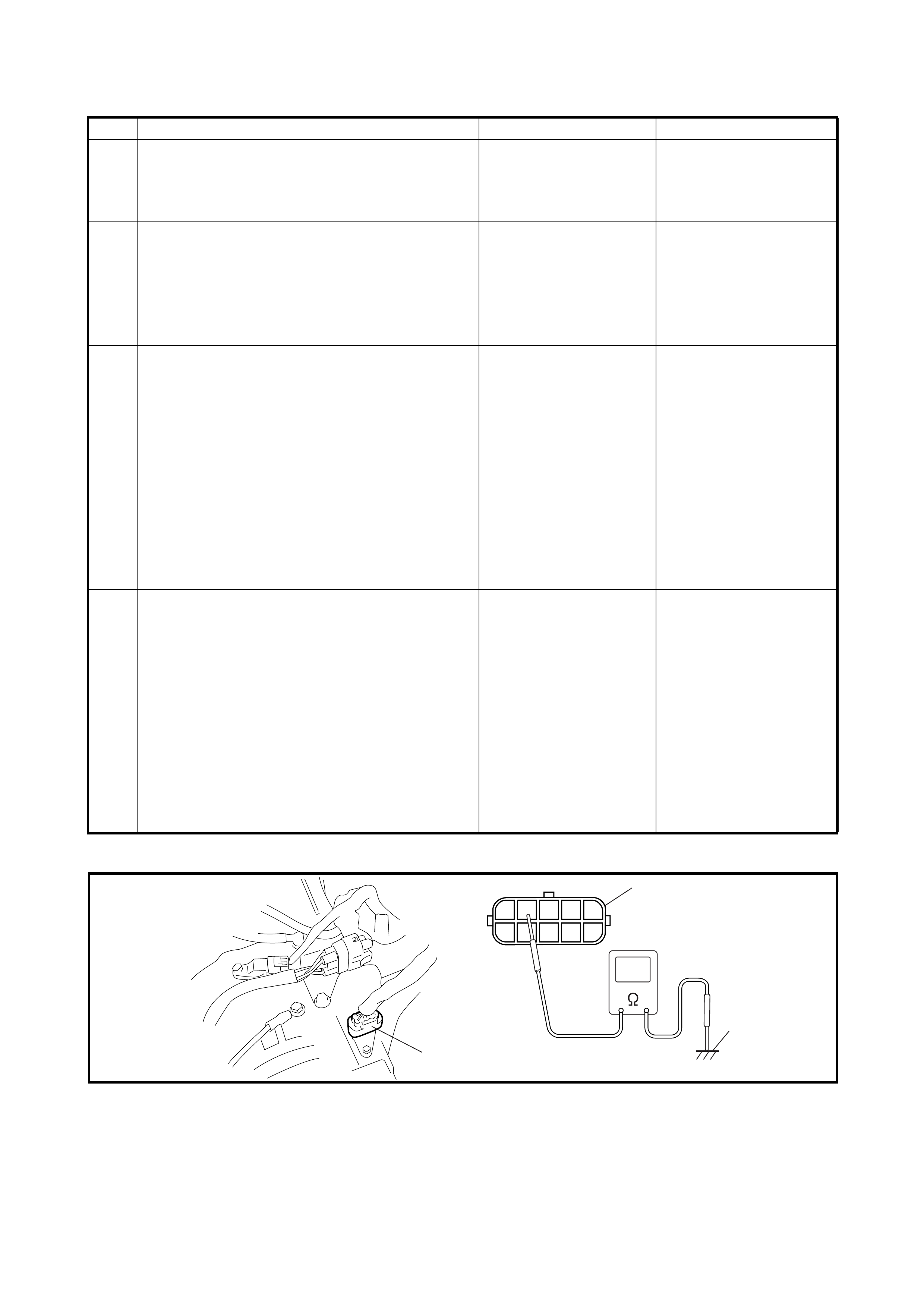
TROUBLESHOOTING
Fig. for Step 3
Legend
Step Action Yes No
1 Was 2.4 AUTOMATIC TRANSAXLE
DIAGNOSTIC FLOW TABLE performed? Go to Step 2. Go to 2.4 AUTOMATIC
TRANSAXLE
DIAGNOSTIC FLOW
TABLE in this section.
2 Check TCC Solenoid Valve Circuit for IG Short
or Open.
1. Turn ignition switch ON and measure
voltage between terminal C44-12 of
harness side TCM connector and ground.
Is it 0 – 1 V?
Go to Step 3. WHT/BLU circuit shorted
to power circuit or open.
3 Check TCC Solenoid Valve Resistance.
2. Turn ignition switch OFF.
3. Disconnect valve body harness connector
on transaxle.
4. Check for proper connection to solenoid
valve at WHT/BLU circuit.
5. Check resistance of solenoid valve. See
Fig. Resistance between terminal of
transaxle side valve body harness
connector and transaxle: 11 – 15 Ω (at
20°C)
Is check result satisfactory?
Go to Step 4. Replace TCC solenoid
valve or lead wire.
4 Check TCC Solenoid Valve Circuit for Ground
Short.
1. Connect valve body harness connector.
2. Disconnect TCM connectors.
3. Measure resistance between terminal C44-
12 of disconnected harness side TCM
connector and ground.
Is it 11 – 15 Ω (at 20°C)?
Intermittent trouble or
faulty T CM.
Check for inter mi tten t,
refer to Section 0A,
1.7 ELECTRICAL
CIRCUIT INSPECTION
PROCEDURE.
INTERMITTENT AND
POOR CONNECTION
If OK, substitute a
known-good TCM and
recheck.
WHT/BLU circuit shorted
to ground.
1
6
7
89
10
5432
1
2
3
1. Valve body harness
connector on harness 2. Valve body harness
connector on transaxle 3. Ground (Transaxle)
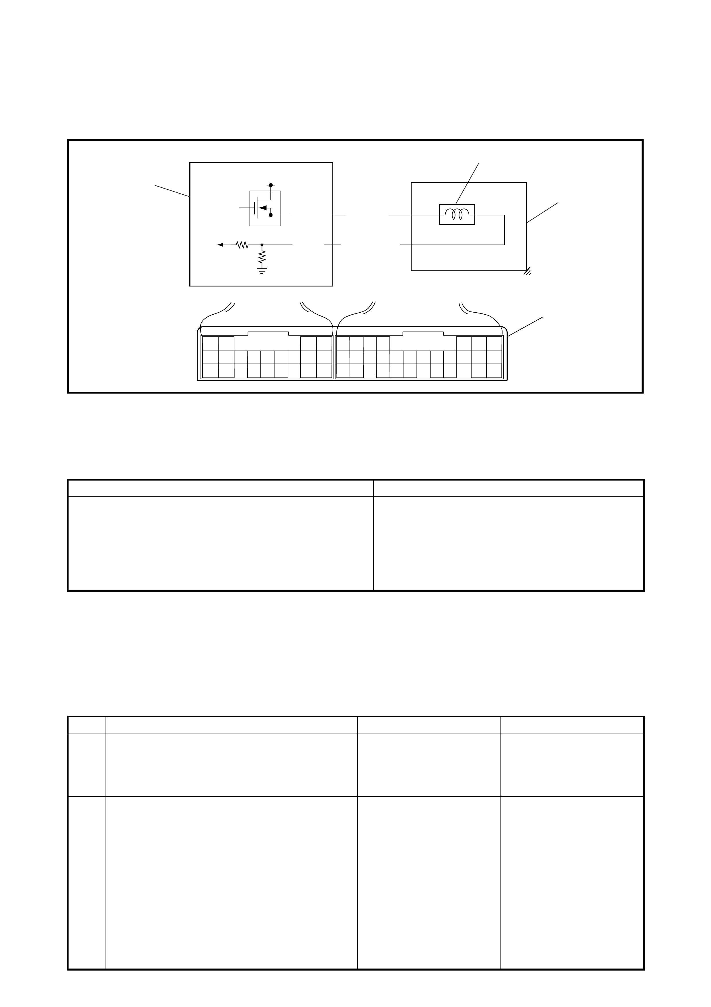
2.31 DTC P0 748/DTC NO.41 OR NO.42 PRES SURE CONTROL SOLENOID
ELECTRICAL
WIRING DIAGRAM
Legend
DTC DETECTING CONDITION AND TROUBLE AREA
DTC CONFIRMATION PROCEDURE
1. Connect Tech 2 to the DLC with the ignition switch OFF.
2. Clear the DTC in the TCM memory.
3. Start the engine and run if for 1 minute.
4. Check the DTC.
TROUBLESHOOTING
11 8
C44 G99
12V
C44-11
C44-8
BRN/YEL
LT GRN/RED
3
2
4
1
1. TCM 2. Pressure control solenoid valve 4. Terminal arrangement of TCM
connector (viewed from harness side)
3. A/T
DTC DETECTING CONDITION T ROUBLE AREA
• Too much electric flow is detected on pressure control
solenoid valve circuit.
or
• No electric flow is detected on pressure control sole-
noid valve circuit.
• Pressure control solenoid valve circuit shorted
to power circui t.
• Pressure control solenoid valve circuit open or
shorted to ground.
• Pressure control solenoid valve malfunction.
•TCM
Step Action Yes No
1Was 2.4 AUTOMATIC TRANSAXLE
DIAGNOSTIC FLOW TABLE p erformed? Go to Step 2. Go to 2.4 AUTOMATIC
TRANSAXLE
DIAGNOSTIC FLOW
TABLE in this Section.
2Check Pressure Control Solenoid Valve Circuit
for IG Short.
1. Turn ignition switch OFF and discon nect
TCM connectors.
2. Check for proper connection to TCM at
terminals C44-11 and C44-8.
3. If OK, turn ignition switch ON and
measure voltage between terminal C44-
11 of disconnected harness side TCM
connector and ground.
Is it 0 – 1 V?
Go to Step 3. BRN/YEL or LT GRN/
RED circuit shorted to
power circuit.
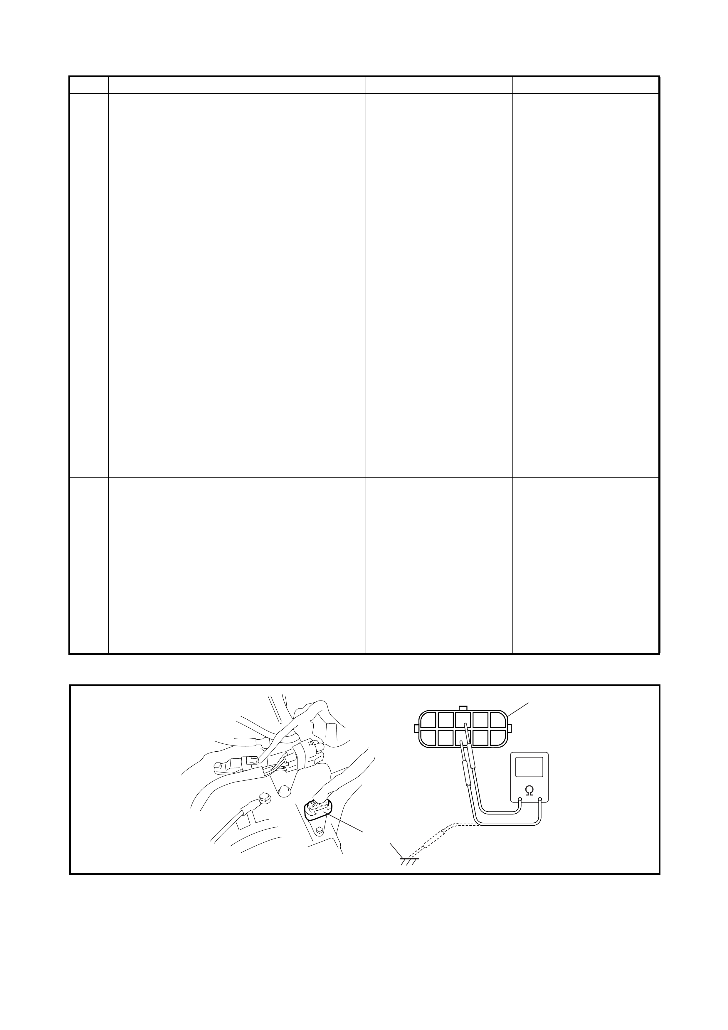
Fig. for Step 3
Legend
3 Check Pressure Control Solenoid Valve
Resistance.
1. Tur n ign ition swi tc h OFF.
2. Disconnect valve body harness
connector on transaxle.
3. Check for proper connection to solenoid
valve at BRN/YEL and LT GRN/RED
circuits.
4. Check resistance of solenoid valve. See
Fig.
Resistance between terminals of
transaxle side valve body harness
connector: 5.0 – 5.6 Ω (at 20°C)
Resistance between terminal of
transaxle side valve body harness
connector and transaxle: Infinity
Is check results satisfactory?
Go to Step 4. Replace pressure control
solenoid valve or lead
wire.
4 Check Pressure Control Solenoid V alve Circuit
for Ground Short.
1. Connect valve body harness connector.
2. Check continuity between terminal C44-
11 of disconnected harness side TCM
connector and ground.
Is continuity indicated?
BRN/YEL or LT GRN/
RED circuit shorted to
ground.
Go to Step 5.
5 Check Pressure Control Solenoid V alve Circuit
for Open.
Check resistance between terminals C44-1 1
and C44-8 of disconnected harness side
TCM connector.
Is it infinity?
BRN/YEL or LT GRN/
RED circuit open. Intermittent trouble or
faulty TCM.
Check for intermittent,
refer to Section 0A,
1.7 ELECTRICAL
CIRCUIT INSPECTION
PROCEDURE.
INTERMITTENT AND
POOR CONNECTION
If OK, substitute a known-
good TCM and recheck.
Step Action Yes No
1
6
7
89
10
5432
1
2
3
1. Valve body harness
connector on harness 2. Valve body harness
connector on transaxle 3. Ground (Transaxle)
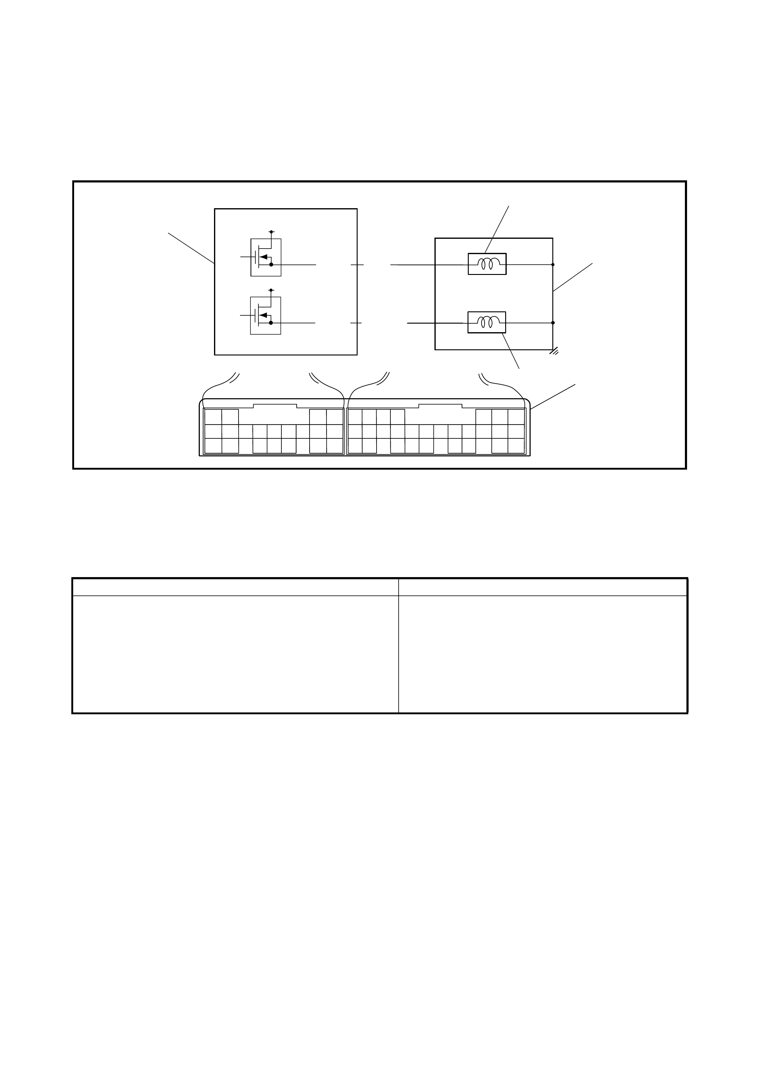
2.32 DTC P0753/DTC NO.21 OR NO.22 SHIFT S OLENOID-A (NO.1) ELECTRICAL
Refer to 2.33 for DTC information.
2.33 DTC P0758/DTC NO.23 OR NO.24 SHIFT S OLENOID-B (NO.2) ELECTRICAL
WIRING DIAGRAM
Legend
DTC DETECTING CONDITION AND TROUBLE AREA
DTC CONFIRMATION PROCEDURE
WARNING:
• When performing a road test, select an area where there is no traffic and exercise extreme caution.
• Road test should be carried out on a level road with 2 persons, a driver and tester.
1. Connect Tech 2 to the DLC with the ignition switch OFF.
2. Clear the DTC in the TCM memory.
3. Start the engine and shift the selector lever to D range.
4. Increase the vehicle speed until 3rd or 4th gear is automatically selected.
5. Decrease vehicle speed and stop the vehicle.
6. Repeat Step 4 and Step 5 at least 4 times.
7. Check the DTC.
3
C44 G99
12V
C44-3 BLK/YEL
12V
C44-4 BRN 4
2
5
1
3
4
1. TCM 3. Shift solenoid valve-B (No.2) 5. Terminal arrangement of TCM
connector (viewed from
harness side)
2. Shift solenoid valve-A
(No.1) 4. A/T
DTC DETECTING CONDITION T ROUBLE AREA
• Voltage of shift solenoid valve TCM terminal is low
although TCM is commanding shift solenoid valve to
turn ON.
or
• Voltage of shift solenoid valve TCM terminal is high
although TCM is commanding shift solenoid valve to
turn OFF.
• Shift solenoid valve circuit shorted to ground.
• Shift solenoid valve circuit open or shorted to
power circuit.
• Shift solenoid valve malfunction.
•TCM

TROUBLESHOOTING
Fig. for Step 3
Legend
Step Action Yes No
1Was 2.4 AUTOMATIC TRANSAXLE
DIAGNOSTIC FLOW TABLE performed? Go to Step 2. Go to 2.4 AUTOMATIC
TRANSAXLE
DIAGNOSTIC FLOW
TABLE in thi s Sec tio n.
2Check Shift Solenoid Valve Circuit for IG Short.
1. Turn ignition switch OFF and disconnect
TCM connectors.
2. Check for proper connection to TCM at
terminal C44-4 or C44-3 of TCM connector .
3. If OK, tur n ig niti on swi tch ON and meas ur e
voltage between terminal C44-4 or C44-3
of disconnected harness side TCM
connector and ground.
Is it 0 – 1 V?
Go to Step 3. BRN or BLK/YEL circuit
shorted to power circuit.
3Check Shift Solenoid Valve Resistance.
1. Turn ignition switch OFF.
2. Disconnect valve body harness connector
on transaxle.
3. Check for proper connection to solenoid
valve at BRN or BLK/YEL circuit.
4. Check resistance of solenoid valves. See
Fig.
Resistance between terminal of transaxle
side valve body harness connector and
transaxle: 11 – 15 Ω (at 20°C)
Is check result satisfactory?
Go to Step 4. Replace shift solenoid
valve or lead wire.
4
Check Shift Solenoid Valve Circuit for Ground
Sho rt or Op en .
1. Connect valve body harness connector.
2. Measure resistance between terminal C44-
4 or C44-3 of disconnected harness side
TCM connector and ground.
Is it 11 – 15 Ω (at 20°C)?
Intermittent trouble or
faulty T CM.
Check for inter mi tten t,
refer to SSection 0A,
1.7 ELECTRICAL
CIRCUIT INSPECTION
PROCEDURE.
INTERMITTENT AND
POOR CONNECTION
If OK, substitute a
known-good TCM and
recheck.
BRN or BLK/YEL circuit
shorted to ground or
open.
1
6
7
89
10
5432
1
2
5
3
4
1. Valve body harne ss
connector on harness 3. Shift solenoid valve-A (No.1) ter-
minal 5. Ground (Transaxle)
2. Valve body harne ss
connector on transaxle 4. Shift solenoid valve-B (No.2) ter-
minal
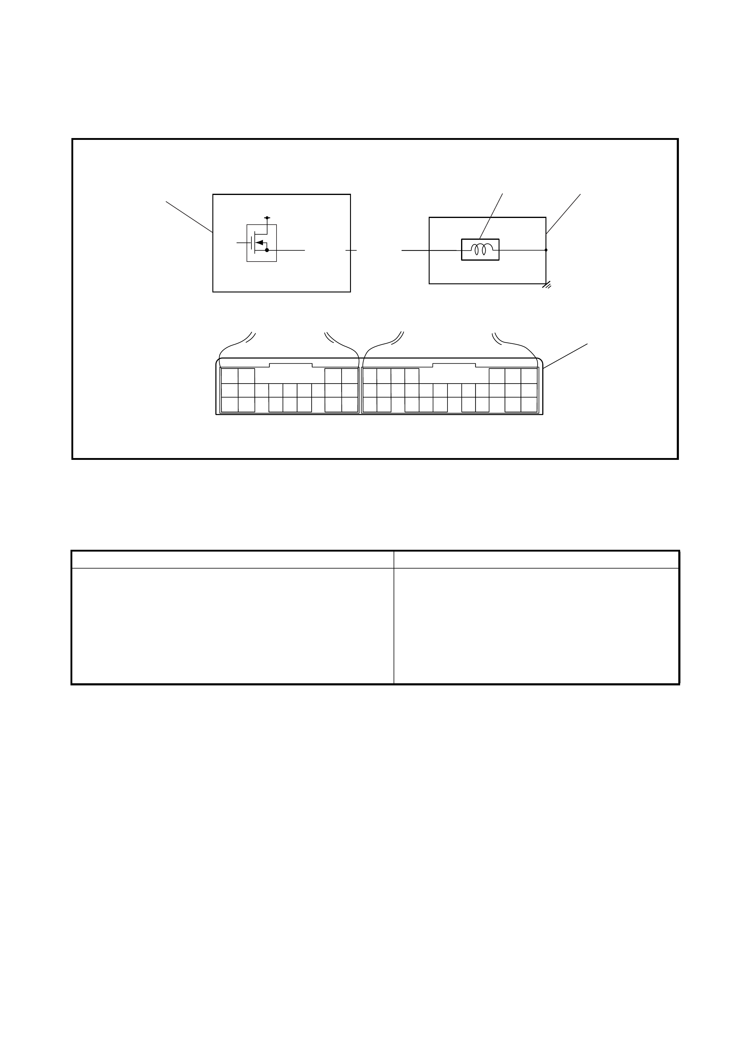
2.34 DTC P0785/DTC NO.13 TIMING SOLENOID
WIRING DIAGRAM
Legend
DTC DETECTING CONDITION AND TROUBLE AREA
DTC CONFIRMATION PROCEDURE
1. Connect Tech 2 to the DLC with the ignition switch OFF.
2. Clear the DTC in the TCM memory.
3. Start the engine and shift the selector lever to N range.
4. Shift the selector lever from N range to D range and repeat 3 times.
5. Check the DTC.
10
C44 G99
12V
C44-10 WHT/RED
3
2
4
1
1. TCM 3. A/T 4. Terminal arrangement of TCM
connector (viewed from harness side)
2. Timing solenoid valve
DTC DETECTING CONDITION T ROUBLE AREA
• Voltage of timing solenoid valve TCM terminal is low
although TCM is commanding timing solenoid valve to
turn ON.
or
• Voltage of timing solenoid valve TCM terminal is high
although TCM is commanding timing solenoid valve to
turn OFF.
• Timing solenoid valve circuit shorted to ground.
• T iming solenoid valve circuit open or shorted to
power circuit.
• Timing solenoid valve malfunction.
•TCM
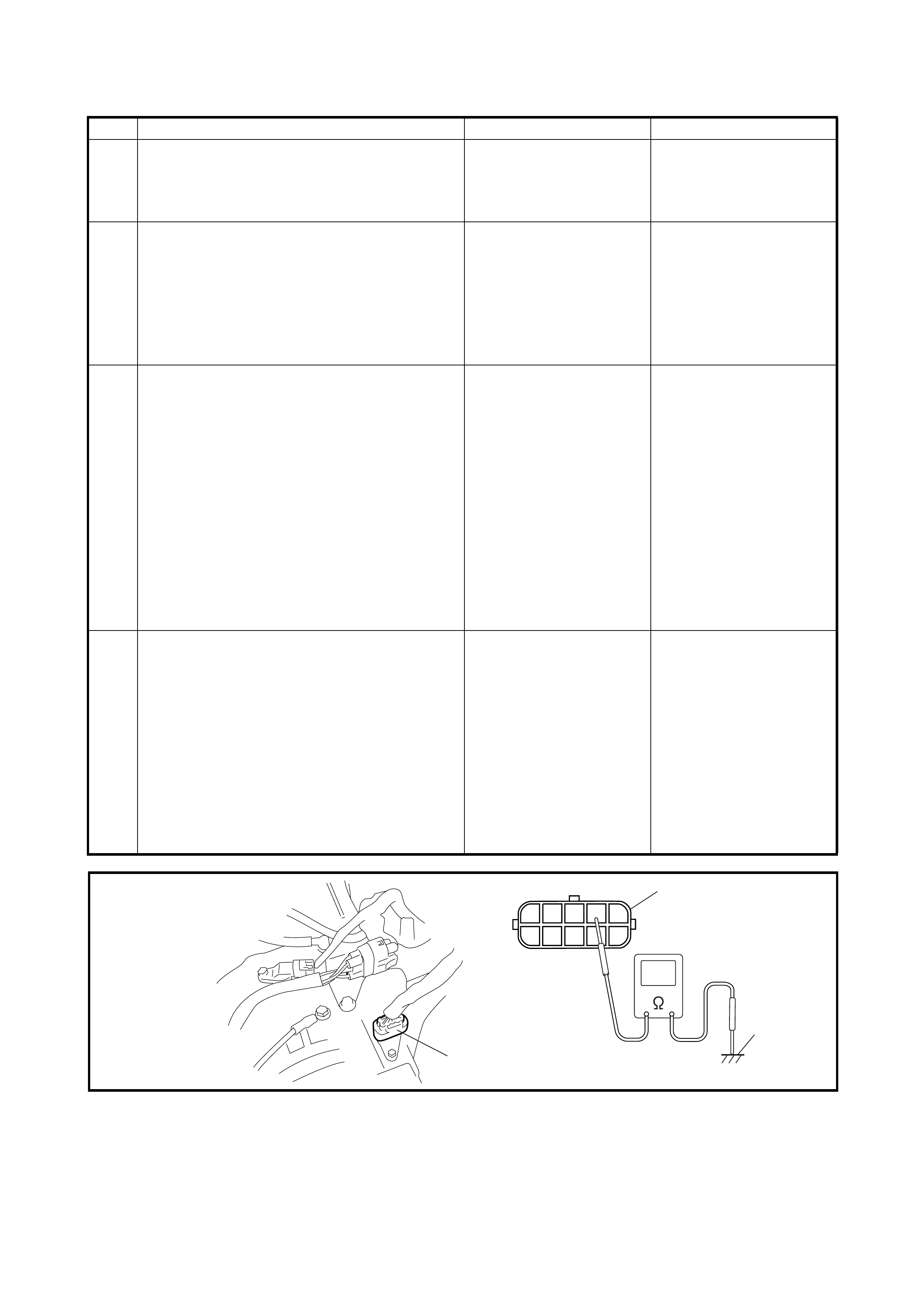
TROUBLESHOOTING
Legend
Step Action Yes No
1 Was 2.4 AUTOMATIC TRANSAXLE
DIAGNOSTIC FLOW TABLE p erformed? Go to Step 2. Go to 2.4 AUTOMATIC
TRANSAXLE
DIAGNOSTIC FLOW
TABLE in this Section.
2 Check Timing Solenoid Valve Circuit for IG
Short or Open.
1. Turn ignition switch ON and measure
voltage between terminal C44-10 of
harness side TCM connector and
ground.
2. Is it 0 – 1 V?
Go to Step 3. WHT/RED circuit shorted
to power circuit or open.
3
Check Timing Solenoid Valve Resistance
1. Tur n ign ition swi tc h OFF.
2. Disconnect valve body harness
connector on transaxle.
3. Check for proper connection to solenoid
valve at WHT/RED circuit.
4. Check resistance of solenoid valve. See
Fig.
Resistance between terminal of
transaxle side valve body harness
connector and transaxle:
11 – 15 Ω (at 20°C)
Is check result satisfactory?
Go to Step 4. Replace timing solenoid
valve or lead wire.
4 Check Timing Solenoid Valve Circuit for
Ground Short.
1. Connect valve body harness connector.
2. Disconnect TCM connectors.
3. Measure resistance between terminal
“C44-10” of disconnected harness side
TCM connector and ground.
Is it 11 – 15 Ω (at 20°C)
Intermittent trouble or
faulty T CM.
Check for inter mi tten t,
refer to Section 0A,
1.7 ELECTRICAL
CIRCUIT INSPECTION
PROCEDURE.
INTERMITTENT AND
POOR CONNECTION.
If OK , substitute a kn ow n -
good TCM and recheck.
WHT/RED circuit shorted
to ground.
1
6
7
89
10
5432
1
2
3
1. Valve body harness
connector on harness 2. Valve body harness
connector on transaxle 3. Ground (Transaxle )
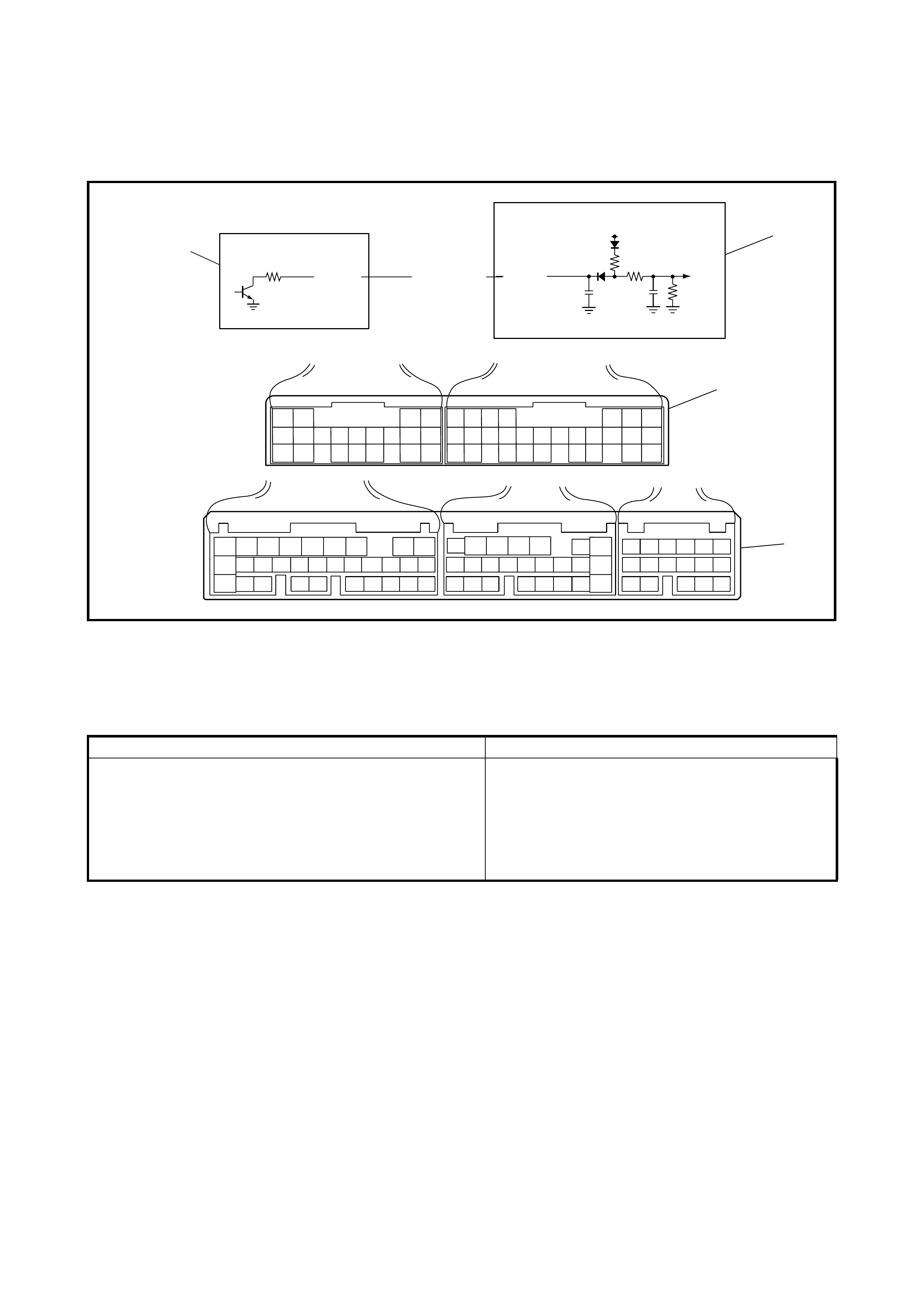
2.35 DTC P1700/DTC NO.32 OR NO.33 THROTTLE POSITION SIGNAL
CIRCUIT MALFUNCTION
WIRING DIAGRAM
Legend
DTC DETECTING CONDITION AND TROUBLE AREA
DTC CONFIRMATION PROCEDURE
1. Connect Tech 2 to the DLC with the ignition switch OFF.
2. Clear the DTC in the TCM memory.
3. Turn the ignition switch ON.
4. Depress the accelerator pedal fully and keep it depressed for 10 seconds.
5. Release the accelerator pedal and wait for 10 seconds.
6. Check the DTC.
6
C44 G99
12V
LT GRN/RED
G02-15 G99-6
2
3
4
C42 C41 G02
15
1
1. TCM 3. Terminal arrangement of TCM con-
nector (viewed from harness side) 4. Terminal arrangement of ECM con-
nector (viewed from harness side)
2. ECM
DTC DETECTING CONDITION T ROUBLE AREA
• Too short low signal of pulse signal from ECM to TCM
continues out of specification.
• Too long low signal of pulse signal from ECM to TCM
continues out of specification.
• Throttle position sensor or its circuit malfunc-
tion.
• Throttle position signal circuit from ECM to
TCM open or short.
•TCM
•ECM

TROUBLESHOOTING
Step Action Yes No
1 Was 2.4 AUTOMATIC TRANSAXLE
DIAGNOSTIC FLOW TABLE p erformed? Go to Step 2. Go to 2.4 AUTOMATIC
TRANSAXLE
DIAGNOSTIC FLOW
TABLE in this Section.
2 Is there DTC related to throttle position sensor
(P0120)? Go to corresponding DTC
Flow Tab le in Secti on 6. Go to Step 3.
3 Check Throttle Position Signal Circuit for IG
Short.
1. Tur n ign ition swi tc h OFF.
2. Disconnect TCM and ECM connectors
from TCM and ECM.
3. Check proper connection to TCM at
terminal G99-6 and to ECM at terminal
G02-15.
4. If OK, turn ignition switch ON and
measure voltage between terminal G99-
6 of disconnected harness side TCM
connector and ground.
Is it 10 – 14 V?
LT GRN/RED circuit
shorted to power circuit. Go to Step 4.
4 Check Throttle Position Signal Circuit for
Open.
1. Tur n ign ition swi tc h OFF.
2. Check continuity between terminal G99-6
of disconnected harness side TCM
connec tor and terminal G 02-15 of discon -
nected harness side ECM connector.
Is continuity indicated?
Go to Step 5. LT GRN/RED circuit
open.
5 Check Throttle Position Signal Circuit for
Ground Short.
Check continuity between terminal G99-6 of
disconnected harness side TCM connector
and ground.
Is continuity indicated?
LT GRN/RED circuit
shorted to ground. Intermittent trouble or
faulty TCM or ECM.
Check for intermittent,
refer to Section 0A,
1.7 ELECTRICAL
CIRCUIT INSPECTION
PROCEDURE.
INTERMITTENT AND
POOR CONNECTION.
If OK, substitute a known-
good TCM or ECM and
recheck.

2.36 DTC P1702/DTC NO.52 INTERNAL MALFUNCTION OF TCM
DTC DETECTING CONDITION AND TROUBLE AREA
DTC CONFIRMATION PROCEDURE
1. Connect Tech 2 to the DLC with the ignition switch OFF.
2. Clear the DTC in the TCM memory.
3. Wait 10 seconds after turning the ignition switch ON, then check the DTC.
TROUBLESHOOTING
DTC DETECTING CONDITION T ROUBLE AREA
Calculation of current data stored in TCM is not correct
comparing with pre-stored checking data in TCM. TCM
Step Action Yes No
1Is DTC P1702/DTC No.52 detected after per-
forming DTC CONFIRMATION
PROCEDURE?
Faulty TCM.
Replace TCM. Could be a temporary
malfunction of the TCM.
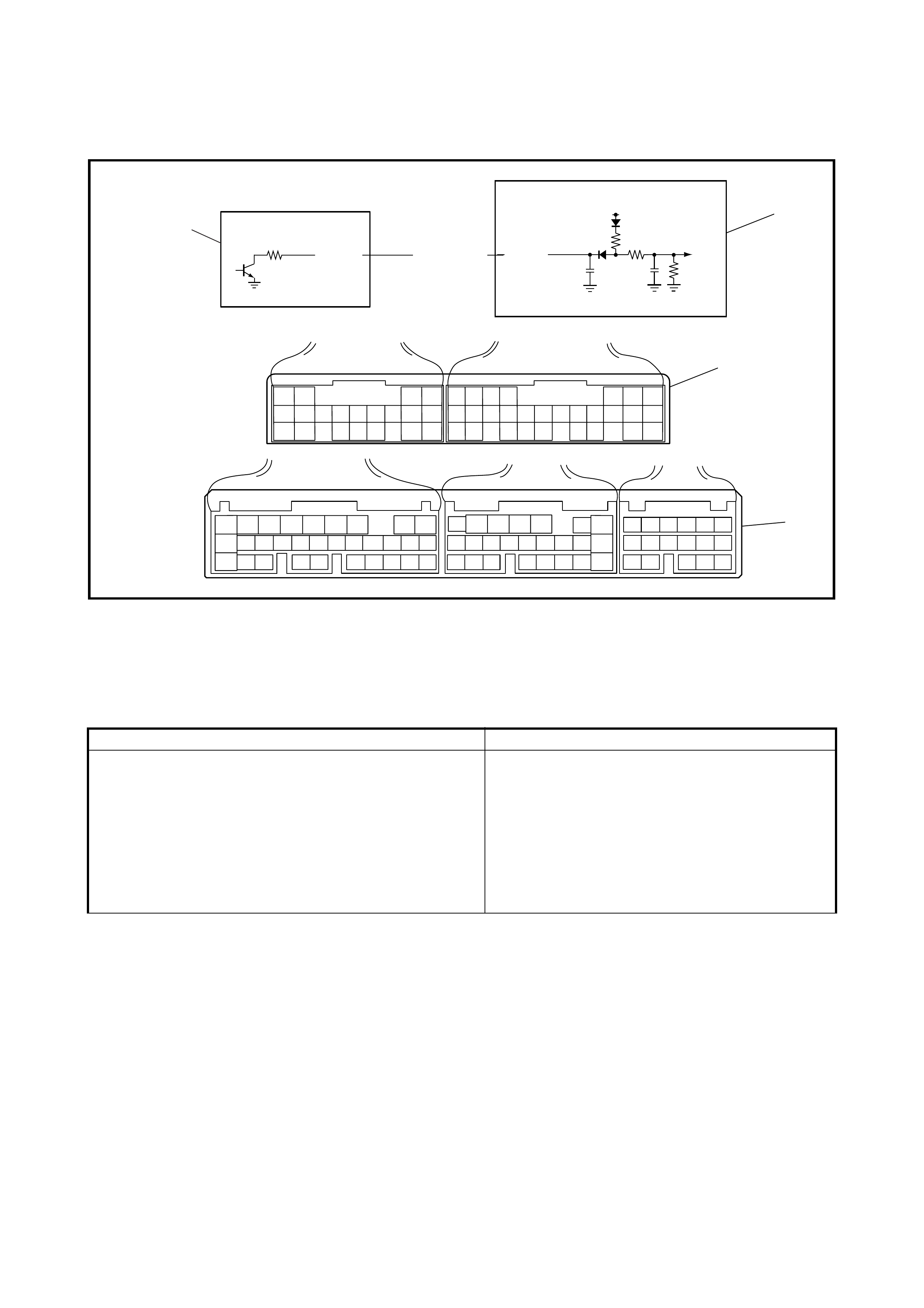
2.37 DTC P1705/ DTC NO.51 ENGINE COOLANT TEMPERATURE SIGNAL
CIRCUIT MALFUNCTION
WIRING DIAGRAM
Legend
DTC DETECTING CONDITION AND TROUBLE AREA
DTC CONFIRMATION PROCEDURE
1. Connect Tech 2 to the DLC with the ignition switch OFF.
2. Clear the DTC in TCM memory.
3. Wait 2 minutes after turning the ignition switch ON, then check the DTC.
7
C44 G99
12V
GRY/RED
G02-17 G99-7
2
3
4
C42 C41 G02
17
1
1. TCM 3. Terminal arrangement of TCM
connector (viewed from harness
side)
4. Terminal arrangement of ECM
connector (viewed from harness
side)
2. ECM
DTC DETECTING CONDITION TROUBLE AREA
• Too long high signal of pulse signal from ECM to TCM
continue s out of speci fic ati on.
or
• Too long low signal of pulse signal from ECM to TCM
continue s out of speci fic ati on.
or
• Too long or short low signal of pulse signal from ECM
to TCM is detected in continues 8 pulses.
• Engine coolant temperature sensor or its circuit
malfunction.
• Engine coolant temperature signal circuit from
ECM to TCM open or short.
•TCM
•ECM

TROUBLESHOOTING
Step Action Yes No
1Was 2.4 AUTOMATIC TRANSAXLE DIAG-
NOSTIC FLOW TABLE performed? Go to Step 2. Go to 2.4 AUTOMATIC
TRANSAXLE
DIAGNOSTIC FLOW
TABLE in this Section.
2Is there DTC related to throttle position sensor
(P0115)? Go to corresponding DTC
Flow Table in Section 6. Go to Step 3.
3Check Engine Coolant Temperature Signal
Circuit for IG Short.
1. Turn ignition switch OFF.
2. Disconnect TCM and ECM connectors
from TCM and ECM.
3. Check proper connection to TCM at
terminal G99-7 and to ECM at terminal
G02-17.
4. If OK, turn ignition switch ON and
measure voltage between terminal G99-
7 of disconnected harness side TCM
connector and ground.
Is it 10 – 14 V?
GRY/RED circuit shorted
to power circuit. Go to Step 4.
4Check Engine Coolant Temperature Signal
Circuit for Open.
1. Turn ignition switch OFF.
2. Check continuity between terminal G99-
7 of disconnected harness side TCM
connector and terminal G02-17 of dis-
connected harness side ECM connector.
Is continui ty indic ate d?
Go to Step 5. GRY/RED circuit open.
5Check Engine Coolant Temperature Signal
Circuit for Ground Short.
Check continuity between terminal G99-7 of
disconnected harness side TCM connector
and ground.
Is continui ty indic ate d?
GRY/RED circuit shorted
to ground. Go to Step 6.
6Inspect Engine Coolant Temperature Sensor.
Inspect engine coolant temperature sensor
referring to 3.8 ENGINE COOLANT
TEMPERATURE SENSOR, INSPECTION.
Is inspection result OK ?
Intermit tent tr ouble or
faulty TCM or ECM.
Check for intermittent,
refer to SSection 0A,
1.7 ELECTRICAL
CIRCUIT INSPECTION
PROCEDURE.
INTERMITTENT AND
POOR CONNECTION
If OK, substitute a known-
good TCM or ECM and
recheck.
Replace eng ine cool ant
temperature sensor.
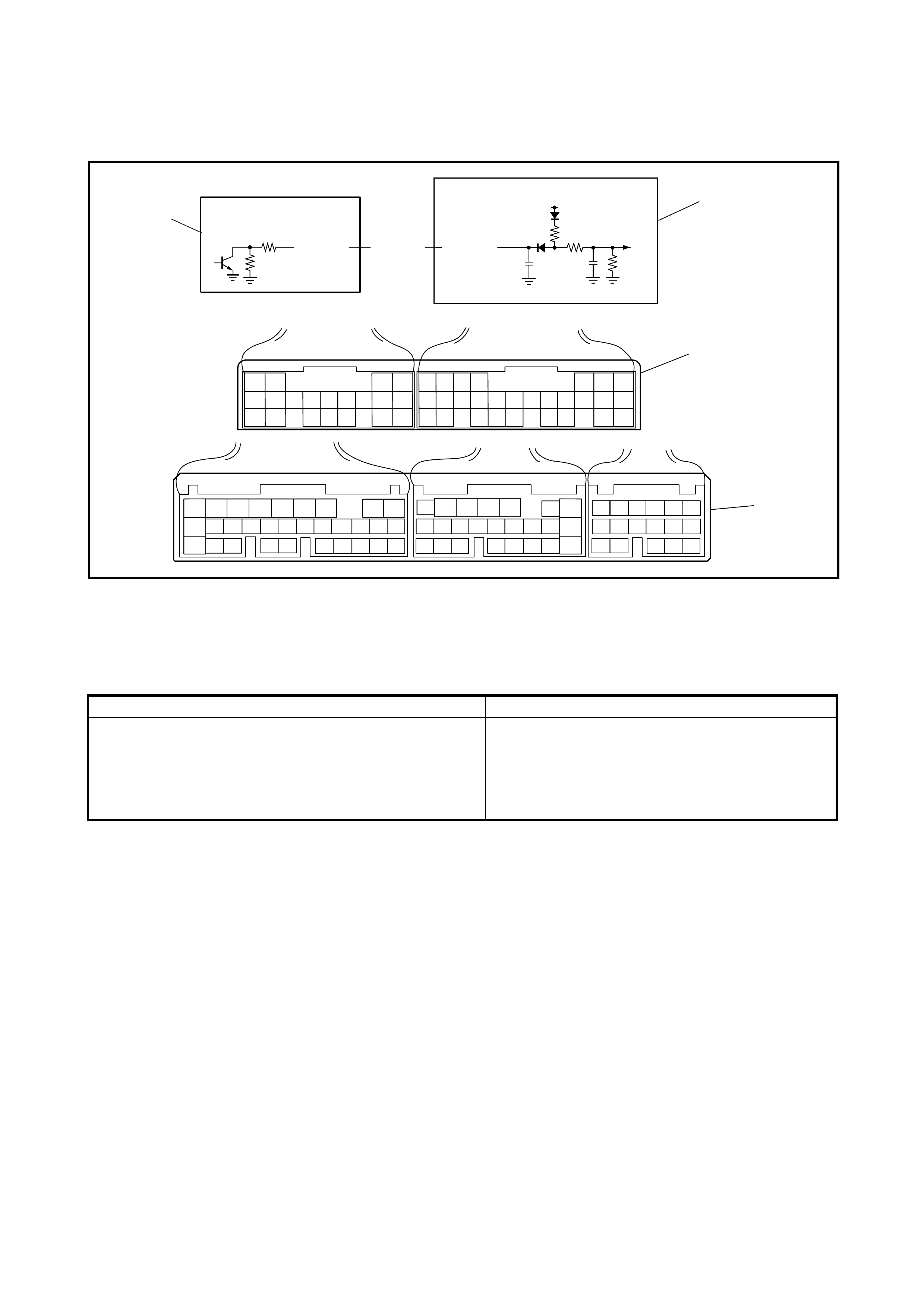
2.38 DTC P173 0/DTC NO.64 ENGINE TORQUE SIGNA L CIR CUIT MALFUNCTION
WIRING DIAGRAM
Legend
DTC DETECTING CONDITION AND TROUBLE AREA
DTC CONFIRMATION PROCEDURE
1. Connect Tech 2 to the DLC with the ignition switch OFF.
2. Clear the DTC in the TCM memory.
3. Wait 1 minute after turning the ignition switch ON, then check the DTC.
23
C44 G99
12V
GRY/YEL
G02-5 G99-23
2
3
4
C42 C41 G02
5
1
1. TCM 3. Terminal arrangement of TCM
connector (viewed from harness side) 4. Terminal arrangement of ECM
connector (viewed from harness side)
2. ECM
DTC DETECTING CONDITION T ROUBLE AREA
• Too short low signal of pulse signal from ECM to TCM
continues out of specification.
or
• Too long low signal of pulse signal from ECM to TCM
continues out of specification.
• Engine torque signal circuit malfunction.
•TCM
•ECM

TROUBLESHOOTING
Step Action Yes No
1 Was 2.4 AUTOMATIC TRANSAXLE
DIAGNOSTIC FLOW TABLE performed? Go to Step 2.
Go to 2.4 AUTOMATIC
TRANSAXLE
DIAGNOSTIC FLOW
TABLE in this Section.
2
Check Engine Torque Signal Circuit for IG
Short.
1. Turn ignition switch OFF.
2. Disconnect TCM and ECM connectors
from TCM and ECM.
3. Check proper connections to TCM at
terminal G99-23 and to ECM at terminal
G02-5.
4. If OK, turn ignition switch ON and
measure voltage between terminal G99-
23 of disconnected harness side TCM
connector and ground.
Is it 10 – 14 V?
GRY/YEL circuit shorted
to power circuit. Go to Step 3.
3 Check Engine Torque Signal Circuit for Open.
1. Turn ignition switch OFF.
2. Check continuity between terminal G99-
23 of disconnected harness side TCM
connec tor and ter minal G 02-5 of dis con-
nected harness side ECM connector.
Is continui ty indic ate d?
Go to Step 4. GRY/YEL circuit open.
4 Check Engine Torque Signal Circuit for
Ground Sho rt .
Check continuity between terminal G99-23 of
disconnected harness side TCM connector
and ground.
Is continuity indicated?
GRY/YEL circuit shorted
to ground. Intermittent trouble or
faulty TCM or ECM.
Check for intermittent,
refer to Section 0A,
1.7 ELECTRICAL
CIRCUIT INSPECTION
PROCEDURE.
INTERMITTENT AND
POOR CONNECTION
.
If OK, substitute a
known-good TCM or
ECM and recheck.
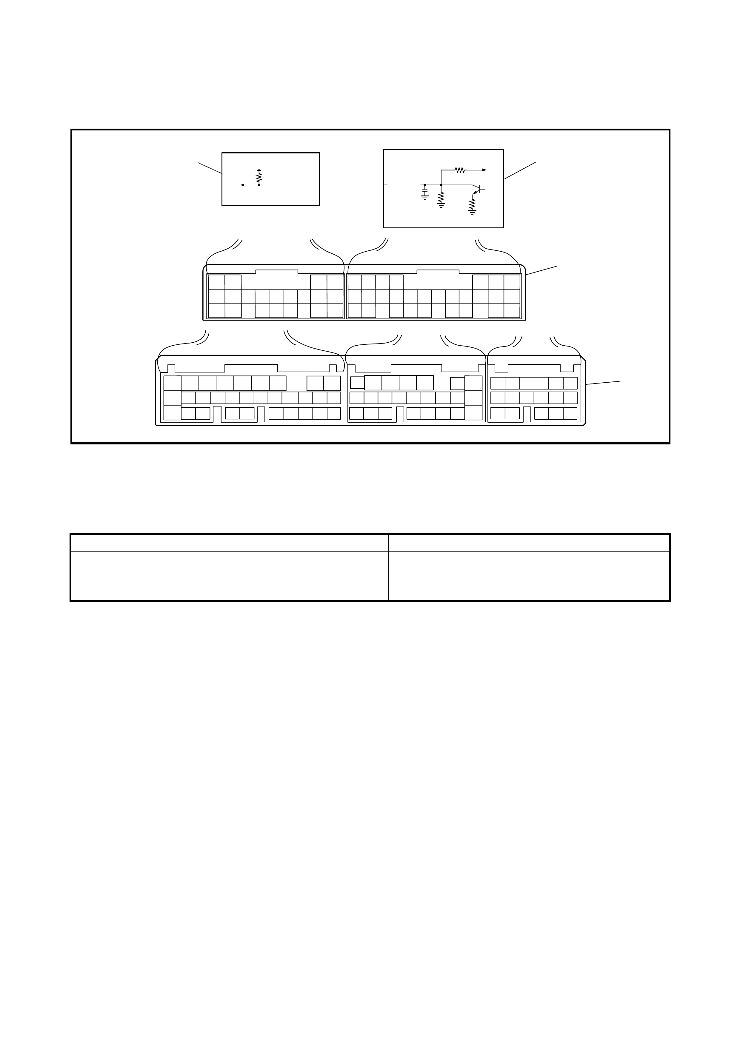
2.39 DTC P1895/DTC NO.27 TORQUE REDUCTION SIGNAL CIRCUIT MALFUNCTION
WIRING DIAGRAM
Legend
DTC DETECTING CONDITION AND TROUBLE AREA
DTC CONFIRMATION PROCEDURE
1. Connect Tech 2 to the DLC with the ignition switch OFF.
2. Clear the DTC in the TCM memory.
3. Wait 1 minute after turning the ignition switch ON, then check the DTC.
18
C44 G99
12V
PNK G99-18G02-12
2
3
1
4
C42 C41 G02
12
1. TCM 3. Terminal arrangement of TCM
connector (viewed from harness side) 4. Terminal arrangement of ECM
connector (viewed from harness side)
2. ECM
DTC DETECTING CONDITION T ROUBLE AREA
V oltage of torque reduction signal circuit TCM terminal is
low although TCM does not require ECM to reduce
engine torque.
• Torque reduction signal circuit malfunction.
•TCM
•ECM

TROUBLESHOOTING
Step Action Yes No
1Was 2.4 AUTOMATIC TRANSAXLE
DIAGNOSTIC FLOW TABLE p erformed? Go to Step 2. Go to 2.4 AUTOMATIC
TRANSAXLE
DIAGNOSTIC FLOW
TABLE in this Section.
2Check Torque Reduction Signal Circuit for
Open.
1. Tur n ign ition swi tc h OFF.
2. Disconnect TCM and ECM connectors
from TCM and ECM.
3. Check continuity between terminal G99-
18 of disconnected harness side TCM
connec tor and terminal G 02-12 of discon -
nected harness side ECM connector.
Is continuity indicated?
Go to Step 3. PNK circuit open.
3Check Torque Reduction Signal Circuit for
Ground Short.
Check continuity between terminal G99-18 of
disconnected harness side TCM connector
and ground.
Is continuity indicated?
PNK circuit shorted to
ground. Go to Step 4.
4Check Power Supply from ECM.
1. Connect ECM connectors to ECM.
2. Tur n ign ition swi tc h ON.
3. Measure voltage between terminal G02-
12 of connected harness side ECM
connector and ground.
Is it 9 – 14 V?
Intermittent trouble or
faulty TCM or ECM.
Check for inter mi tten t,
refer to Section 0A,
1.7 ELECTRICAL
CIRCUIT INSPECTION
PROCEDURE.
INTERMITTENT AND
POOR CONNECTION.
If OK , substitute a kn ow n -
good TCM or ECM and
recheck.
Faulty ECM.

2.40 TEC H 2 DATA
As the data values given below are standard values estimated on the values obtained from the normal opera-
tion of veh icles us ing Tec h 2, use them as referen ce values onl y. Even when the vehi cle is in goo d condi tion,
there may be cases where the checked value does not fall within each specified data range. Therefore, an
assessment of problems should not be made using this data alone.
Also, the conditi ons i n the table below th at can b e chec ked usin g Tech 2 are those det ected b y the TC M and
output from the TCM as commands. There may be cases where the automatic transaxle or actuator is not
operating (in the condition) as indicated by Tech 2.
NOTE: The foll owing Tech 2 data rel ati ng to th e au tom ati c t ran sax le ca n be ch ec ke d on ly by c omm uni c atin g
with the TCM.
Tech 2 DATA VEHICLE CONDITION NORMAL CONDITION
/REFERENCE VALUES
GEAR POSITION Ignition switch ON Selector lever is in P position P or N
Selector lever is in R position R
Selector lever is in N position P or N
Selector lever is in D position 1st
Selector lever is in 2 position 1st
Selector lever is in L position 1st
THROTTLE
POSITION Ignition switch ON Accelerator pedal is released 0%
Accelerator pedal is
depressed 0 – 100%
(V aries depending on depressed
value)
INPUT SHAFT
SPEED Ignition switch ON and engine stop 0 RPM
At 60 km/h constant speed, O/D off switch ON, 20%
or less throttle opening and 3rd gear (D range) Approx. 2350 RPM
OUTPUT SHAFT
SPEED At vehicle stop 0 RPM
At 60 km/h constant speed, O/D off switch ON, 20%
or less throttle opening and 3rd gear Approx. 2350 RPM
VEHICLE SPEED At vehicle stop 0 km/h
BATTERY
VOLTAGE Ignition switch ON and engine stopped Battery voltage is displayed
(8 – 16 V)
TRANSMISSION
FLUID
TEMPERATURE
After driving at 60 km/h for 15 minutes or more, and
A/T fluid temperature around sensor reaches 70 –
80°C
70 – 80°C
PCS DUTY CYCLE At vehicle stop, closed throttle, engine idle speed
and 1st gear 0%
ENGINE SPEED At engine idle speed Engine idle speed is displayed
ENGINE
COOLANT
TEMPERATURE
Ignition switch ON Engine coolant temperature is
displayed
ENGINE TORQUE Ignition switch ON and engine stop 0 Nm
OVERDRIVE OFF
SWITCH Ignition switch ON O/D off switch OFF OFF
O/D off switch ON ON
SELECTOR
POSITION Ignition switch ON Selector lever is in P position P
Selector lever is in R position R
Selector lever is in N position N
Selector lever is in D position D
Selector lever is in 2 position 2
Selector lever is in L position L
SHIFT
SOLENOID-A At vehicle stop ON
At 60 km/h constant speed, O/D off switch ON, 20%
or less throttle opening and 3rd gear OFF

TECH 2 DATA DEFINITIONS:
Gear Position
Current gear position computed by throttle position coming from the ECM and vehicle speed.
Throttle Position (%)
Throttle opening ratio computed by duty pulse signal from the ECM.
Input Shaft Speed (rpm)
Input shaft revolution computed by reference pulses coming from the input shaft speed sensor on the tran-
saxle case.
Outp ut Shaft Speed (rpm)
Output shaft revolution computed by reference pulses coming from the output shaft speed sensor (VSS) on
the transaxle case.
Vehicle Speed (km/h)
Vehi cle speed c omputed by reference p ulse signa ls comi ng from the Vehicle Speed Sensor on t he transa xle
case.
Battery Voltage (V)
Battery voltage read by the TCM as analogue input signal by the TCM.
SHIFT
SOLENOID-A
FEEDBACK
At vehicle stop ON
At 60 km/h constant speed, O/D off switch ON, 20%
or less throttle opening and 3rd gear OFF
SHIFT
SOLENOID-B At vehicle stop ON
At 60 km/h constant speed, O/D off switch ON, 20%
or less throttle opening and 3rd gear OFF
SHIFT
SOLENOID-B
FEEDBACK
At vehicle stop ON
At 60 km/h constant speed, O/D off switch ON, 20%
or less throttle opening and 3rd gear OFF
TCC SOLENOID
VAVLE At 5 km/h constant speed, O/D off switch ON, closed
throttle and 1st gear OFF
At 100km/h constant speed, O/D off switch OFF,
20% or less throttle opening and 4th gear ON
TCC SOLENOID
FEEDBACK At 5 km/h constant speed, O/D off switch ON, closed
throttle and 1st gear OFF
At 100 km/h constant speed, O/D off switch OFF,
20% or less throttle opening and 4th gear ON
TIMING
SOLENOID Ignition switch ON and selector lever is in N range OFF
For about 0.5 sec. while on gear shifting between 3rd
and 4th ON
TIMING
SOLENOID
FEEDBACK
Ignition switch ON and selector lever is in N range OFF
For about 0.5 sec. while on gear shifting between 3rd
and 4th ON
DRIVING MODE Ignition switch ON Selector lever is in P position P/N
Selector lever is in R position DRIVE
Selector lever is in N position P/N
Selector lever is in D position DRIVE
Selector lever is in 2 position DRIVE
Selector lever is in L position DRIVE
A/C SWITCH Ignition switch ON and air conditioner switch OFF OFF
BRAKE SWITCH Ignition switch ON Brake pedal is depressed ACTIVE
Brake pedal is released INACTIVE
TORQUE
REDUCTION While on gear upshifting with 10% or more throttle
opening ACTIVE
Under condition of not shifting gear INACTIVE
Tech 2 DATA VEHICLE CONDITION NORMAL CONDITION
/REFERENCE VALUES

Transmission Fluid Temperature (°C)
Automat ic Trans mission Fluid temperature dec ided by signa l from the tr ansmission fl uid temperatur e sensor
installed on valve body.
PCS Duty Cycle (%)
Electric current value ratio between the electric current value being outputted from the TCM to the solenoid
and the maximum value that can be outputted by TCM.
Engine Speed (rpm)
Engine speed computed by reference pulses from the Crankshaft Position Sensor.
Engine Coolant Temperature (°C)
Engine coolant temperature computed by duty pulse signal from the ECM.
Engine Torque (Nm)
Engine torque computed by duty pulse signal outputted from the ECM.
Overdrive Off Switch
Inputted signal from O/D off switch on selector knob.
ON: O/D off switch ON.
OFF: O/D off switch OFF.
Selector Position
Transaxle range detected by a signal feed from the transmission range sensor.
Shift Solenoid-A
ON: ON command being outputted to the Shift Solenoid Valve-A (No.1).
OFF: ON command not being outputted to the Shift Solenoid Valve-A (No.1).
Shift Solenoid-A Feedback
ON: Current flowing to the Shift Solenoid Valve-A (No.1).
OFF: Current not flowing to the Shift Solenoid Valve-A (No.1).
Shift Solenoid-B
ON: On command being outputted to the Shift Solenoid Valve-B (No.2).
OFF: ON command not being outputted to the Shift Solenoid Valve-B (No.2).
Shift Solenoid-B Feedback
ON: Current flowing to the Shift Solenoid Valve-B (No.2).
OFF: Current not flowing to the Shift Solenoid Valve-B (No.2).
TCC Solenoid Valve
ON: ON command being outputted to the TCC shift solenoid valve.
OFF: ON command not being outputted to the TCC shift solenoid valve.
TCC Solenoid Feedback
ON: Current flowing to the TCC solenoid valve.
OFF: Current not flowing to the TCC solenoid valve.
Timing Solenoid
ON: ON command being outputted to the Timing Solenoid Valve.
OFF: ON command not being outputted to the Timing Solenoid Valve.
Timing Solenoid Feedback
ON: Current flowing to the Timing Solenoid Valve.
OFF: Current not flowing to the Timing Solenoid Valve.
Driving Mode
ON: Signal which the TCM requires the ECM to increase idle speed.
OFF: Signal which the TCM does not require the ECM to increase idle speed.
A/C Switch
ON: Signal which informs that the air conditioner compressor is turned ON.
OFF: Signal which informs that the air conditioner compressor is not turned ON.
Brake Switch
Inputted signal from the brake light switch on the brake pedal bracket.
ON: Brake pedal depressed.
OFF: Brake pedal released.
Torque Reduction
ON: Signal which the TCM requires the ECM to reduce output torque at shifting gear
OFF: Signal which the TCM does not require the ECM to reduce output torque.
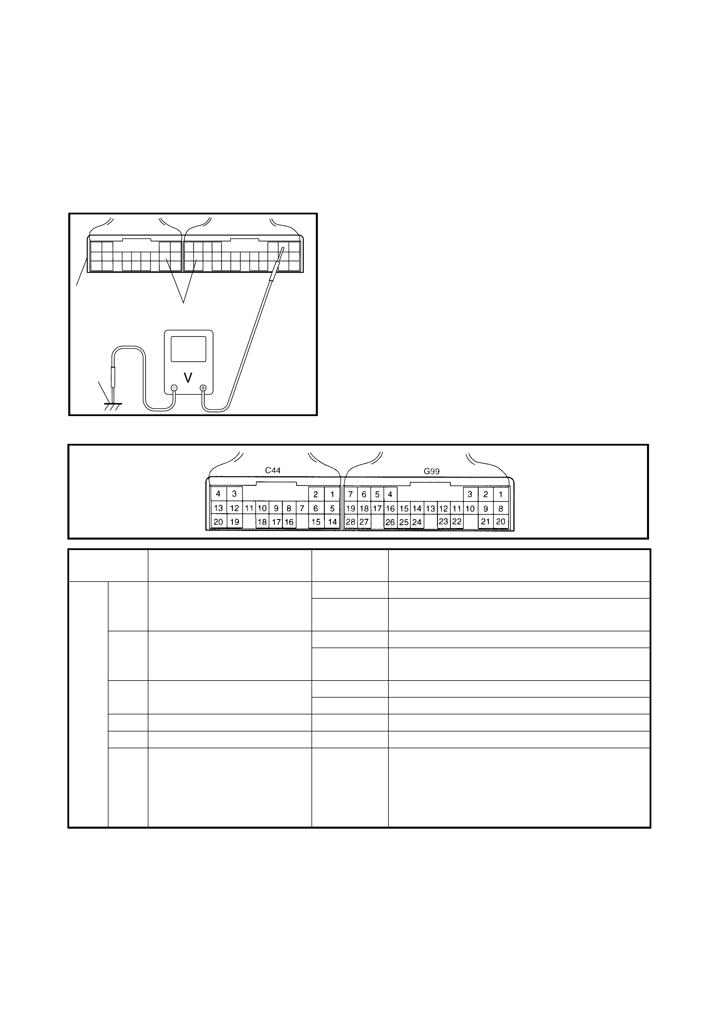
2.41 INSPECTION OF TCM AND ITS CIRCUITS
The TCM and its circuits can be checked at the TCM wiring
connectors by measuring voltage and resistance.
CAUTION: The TCM cannot be checked by itself, it is
strictly prohibited to connect voltmeter or ohmmeter to
the TCM with the connector disconnected from it.
INSPECTION
1. Remove the TCM (1) from the vehicle, refer to
1.5 TRANSMISSION CONTROL MODULE (TCM) in
this Section.
2. Connect the TCM connectors (2) to the TCM.
3. Check the voltage at each terminal with the connectors
connected and the voltmeter grounded (3).
NOTE: As each ter minal v oltage i s affected by ba tter y vo lt-
age, confirm that it is 11 V or more when the ignition switch
is ON.
TERMINAL ARRANGEMENT OF TCM CONNECTOR (VIEWED FROM HARNESS SIDE)
1
2
3
TERMINAL CIRCUIT STANDARD
VOLTAGE CONDITION
G99 1 Tr an smissi on ra nge sens or
(R range) 8 – 14 V Ignition switch ON, selector lever in “R” range
0 – 1 V Ignition switch ON, selector lever in other than
R range
2 Transmis sion ra nge sens or
(P range) 8 – 14 V Ignition switch ON, selector lever in P range
0 – 1 V Igni tion swit ch ON, sel ector le ver in oth er than P
range
3 O/D off switch 0 – 1 V O/D off switch is held in.
8 – 14 V O/D off switch is released.
4Blank – –
5 Input shaft speed sensor (+) 2 – 3 V Ignition switch ON, engine at stop
6 Throttle opening signal (from
ECM) 0 – 1 V Ignition switch ON (Signal from ECM is 128 Hz
active low duty pulse. Duty ratio varies as throt-
tle valve is opened gradually.
Duty On time: 0.78 ms (throttle opening 0%)
6.24 ms (throttle opening 100%)
8 – 14 V

G99 7 Engine coolant temperature
signal (from ECM) 0 – 1 V Ignition switch ON (Signal from ECM is active
low duty pulse. Duty ratio varies depending on
engine coolant temperature.
Duty On time: 850 ms (20°C )
1450 ms (80°C )
8 – 14 V
8 Transmis sion ra nge sens or
(D range) 8 – 14 V Ignition switch ON, selector lever in D range
0 – 1 V Ignition switch ON, selector lever in other than
D range
9 Transmis sion ra nge sens or
(N range) 8 – 14 V Ignition switch ON, selector lever in N range
0 – 1 V Ignition switch ON, selector lever in other than
N range
10 O/D OFF light 0 – 1 V Igniti on switch ON (lamp turned ON)
9 – 14 V Ignition switch ON (lamp turned OFF)
11 Blank – –
12 D range signal 9 – 14 V Ignition switch ON, selector lever in P or N
range
0 – 1 V Igni ti on sw i t ch ON , s el e ct or le ver in R, D, 2 or L
range
13 Blank – –
14 Air conditioner compressor
signal 0 – 1 V Ignition switch ON, A/C compressor turned ON
8 – 14 V Ignition switch ON, A/C compressor turned OFF
15 Engine speed signal 0 – 1 V Ignition switch ON, engine at stop
0 – 1 V While engine running (Signal from ECM is
pulse. Pulse frequency varies depending on
engine speed. (3000 rpm = 100 Hz))
8 – 14 V
16 Blank – –
17 Input shaft speed sensor (–) 2 – 3 V Ignition switch ON
18 Torque reduction signal 9 – 14 V Ignition switch ON
19 Blank – –
20 Transm is sion ra nge sens or
(L range) 8 – 14 V Ignition switch ON, selector lever in L range
0 – 1 V Ignitio n swit ch ON, s elect or leve r in ot her t han L
range
21 Transm is sion ra nge sens or
(2 range) 8 – 14 V Ignition switch ON, selector lever in 2 range
0 – 1 V Ignitio n swit ch ON, s elect or leve r in ot her t han 2
range
22 Blank – –
23 Engine torque signal 0 – 1 V Ignition switch ON (Signal from ECM is 128 Hz
duty pulse. Duty ratio varies depending on
engine torque.)8 – 14 V
24 Output shaft speed sensor 0 – 1 V Ignition switch ON and vehicle running (Signal
from sensor is pulse. Pulse frequency varies
depending on vehicle speed. (4 pulses are gen-
erated per 1 sensor shaft revolution.))8 – 14 V
25 Blank – –
26 Blank – –
G99 27 Data link connector 0 – 1 V Ignition switch ON
8 – 14 V
28 Vehicle speed output 0 – 1 V Ignition switch ON and vehicle running (Output
signal is pulse. Pulse frequency varies depend-
ing on vehicle speed.)8 – 14 V
TERMINAL CIRCUIT STANDARD
VOLTAGE CONDITION

C44 1 Blank – –
2Blank – –
3 Shift solenoid valve-B (No.2) 9 – 14 V Ignition switch ON, selector lever in P range
4 Shift solenoid valve-A (No.1) 9 – 14 V Ignition switch ON, selector lever in P range
5 Transmission temp er atu re
sensor (+) 4.5 – 4.9 V Ignition switch ON, fluid temperature is –30°C
3.3 – 3.7 V Ignition switch ON, fluid temperature is 10°C
0.3 – 0.5 V Ignition switch ON, fluid temperature is 110°C
0.1 – 0.3 V Ignition switch ON, fluid temperature is 145°C
6 Diagnosis switch 8 – 14 V Ignition switch ON
7Blank – –
8 Pressure control solenoid
valve (ground) 0 – 2.5 V Ignition switch ON (Signal is duty pulse. Duty
ratio varies as throttle valve opening.)
9Blank – –
10 Timing solenoid valve 0 – 1 V Ignition switch ON
11 Pressure control solenoid
valve (+) 0 – 1 V Ignition switch ON (Output signal is duty pulse.
Duty ratio varies as throttle valve opening.)
9 – 14 V
12 TCC s olenoid valve 0 – 1 V Ignition switch ON
13 Power source for back-up 10 – 14 V Constantly
14 Transm issi on temp er atu re
sensor (ground) 0 – 1 V Ignition switch ON
15 Ground 0 – 1 V Ignition switch ON
16 Brake light switch 8 – 14 V Ignition switch ON, brake pedal depressed
0 – 1 V Ignition switch ON, brake pedal released
17 Blank – –
18 Blank – –
19 Ground 0 – 1 V Ignition switch ON
20 Power source 10 – 14 V Ignition switch ON
TERMINAL CIRCUIT STANDARD
VOLTAGE CONDITION
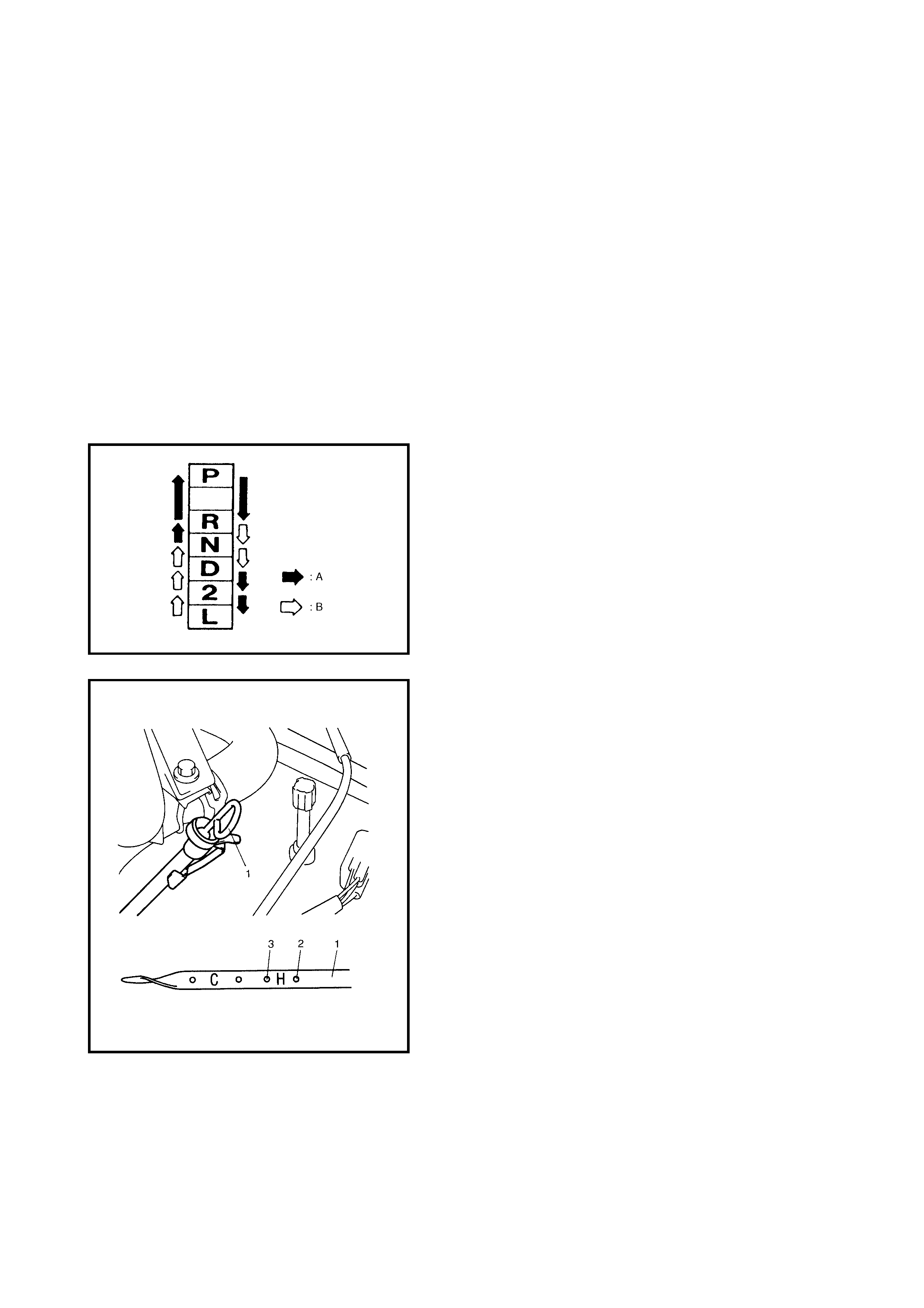
3. ON-VEHICLE SERVICE
3.1 MA INTENANCE SE RVICE
FLUID LEVEL CHECK AT NORMAL OPERATING (HOT) TEMPERATURE (HOT CHECK)
Inspection
1. Stop the vehicle and place it on level ground.
2. Apply the parking brake and place chocks against the
wheels.
3. With the selector at P position, start the engine.
4. Warm up the en gine until the A/T flui d reaches norma l
operating temperature (70 – 80°C). As a guide, this
should occur when the engine reaches normal
operating temperature.
5. Keep the engine idling and shift the selector slowly to L
and back to P position.
6. With the engine idling, pull out the fluid level gauge,
wipe it with a clean cloth and put it back into place.
For the operation of the select lever, refer to the figure.
A - Shift the selector with its button pushed in.
B - Shift the selector without pushing the button in.
7. Pull out the fluid level gauge (1) again and check the
fluid. The lowest fluid level should be between FULL
HOT (2) and LOW HOT (3). If it is below LOW HOT,
add an equivalent of DEXRON
®
-III up to FULL HOT.
Automatic transaxle fluid
: An equivalent of DEXRON
®
-III or DEXRON
®
-IIE
NOTE:
• Do not race the engine while checking the fluid level.
• Do no t overfill. Overfilling can cause foaming and loss
of fluid through the breather. Slippage and transaxle
failure can result .
• Bringing the level from LOW HOT to FULL HOT
require s 0.4 lit re s.
• If the vehicle was driven under heavy load i.e. pulling a
trailer, the fluid level should be checked about half an
hour after it has stopped.
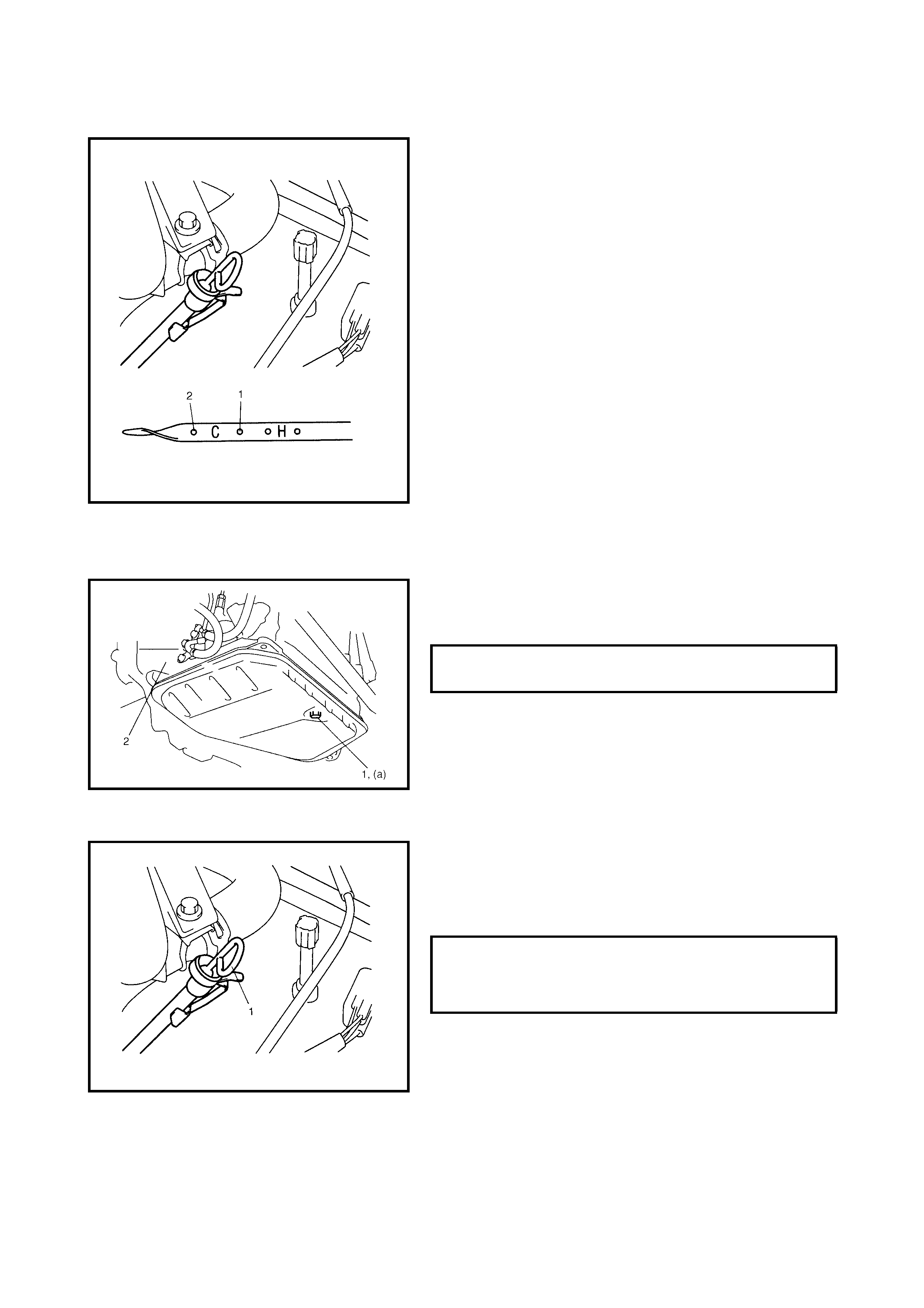
FLUID LEVEL CHECK AT ROOM (COLD) TEMPERATURE (COLD CHECK)
Inspection
The fluid level can be checked temporarily at room (cold)
temperature (20 – 30°C). This level check should be con-
sidered as preparation before performing a level check
under normal the operating (hot) temperature. The check-
ing procedure is the same as NORMAL OPERATING
TEMPERATURE FLUID CHECK as described previously. If
the fluid level i s between FULL COLD ( 1) and LOW COLD
(2), proceed to test drive. When the fluid temperature has
reached normal operating (hot) temperature, check the
fluid level again and adjust it as necessary.
CAUTION:
Fluid lev el check at room (cold ) temperature is recom-
mended only as preparation for a level check under
normal (hot) operating conditions.
Failure to perform a fluid level check under normal
(hot) operating temperatures may result in damage to
the A/T transaxle.
FLUID CHANGE
1. Raise the vehicle on a hoist.
2. When engine is cool, remove the drain plug (1) from
transaxle housing (2) and drain the A/T fluid.
3. Install the drain plug (1).
4. Lower the ve hicle and reple nish th e correct am oun t of
an equivalent of DEXRON
®
-III.
5. Check the fluid level (!), refer to
FLUID LEVEL CHECK.
Automatic transaxle fluid
: An equivalent of DEXRON
®
-III
A/T FLUID DRAIN PLUG (a)
TIGHTENING TORQUE 17 Nm
AUTOMATIC TRANSAXLE FLUID
CAPACITY
WHEN DRAINING FROM DRAIN PLUG
WHEN OVERHAULING 3.3 LITRES
5.6 LITRES
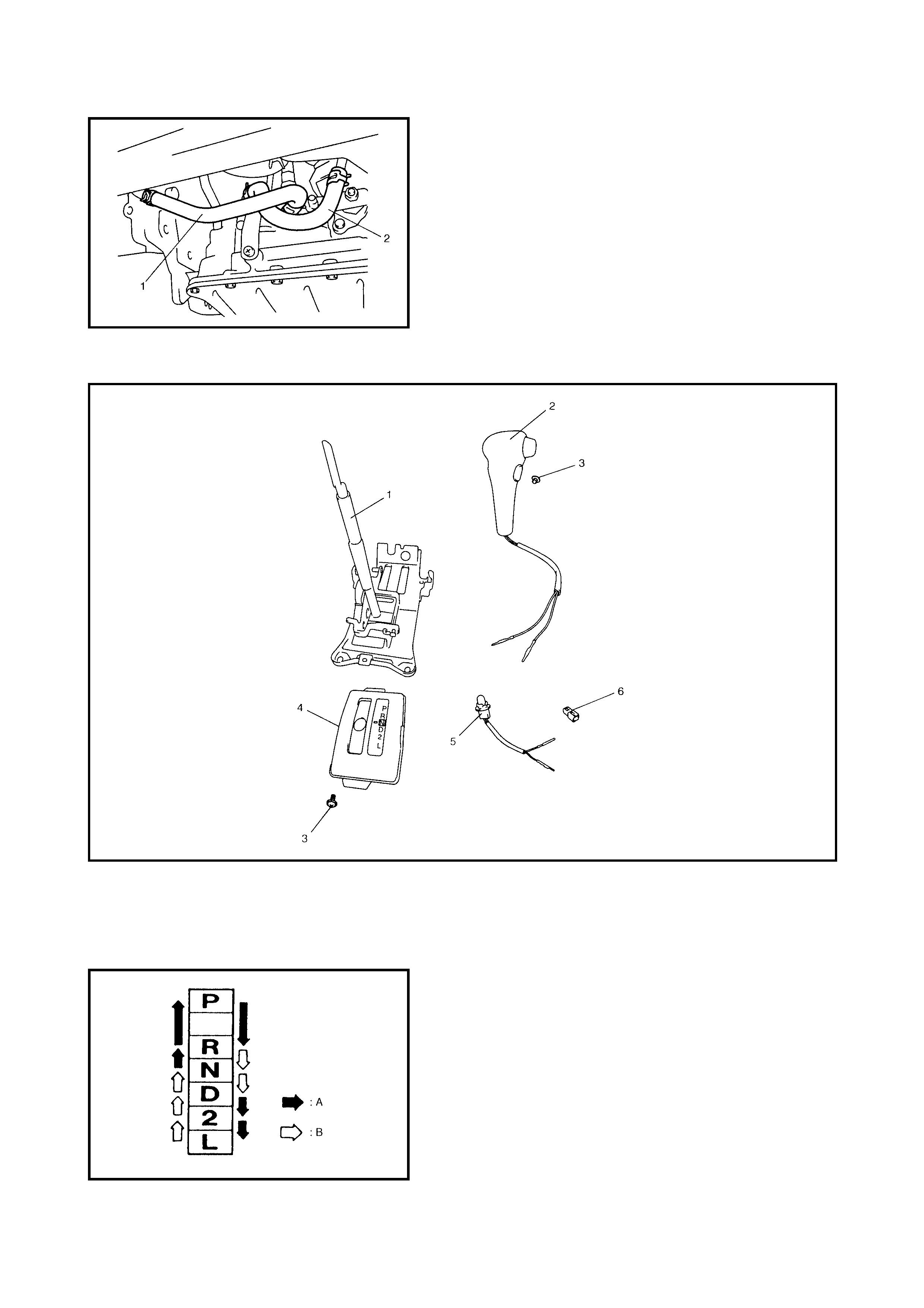
A/T FLUID COOLER HOSES
The rubber hoses (1,2) for the A/T fluid cooler should be
replaced at specified intervals. When replacing them, be
sure to note the following.
• to replace clamps at the same time
• to insert hose as far as its limit mark
• to clamp hose s securely
3.2 SELECTOR LEVE R
Legend
INSPECTION
Check the selector lever for smooth and clear-cut move-
ment and position indicator for correct alignment.
For the operation of the select lever, refer to the figure.
A - Shift the selector with its button pushed in.
B - Shift the selector without pushing the button in.
1. Selector lever assembly 3. Screw 5. Illumination lamp assembly
2. Knob assembly 4. Indicator assembly 6. Connector
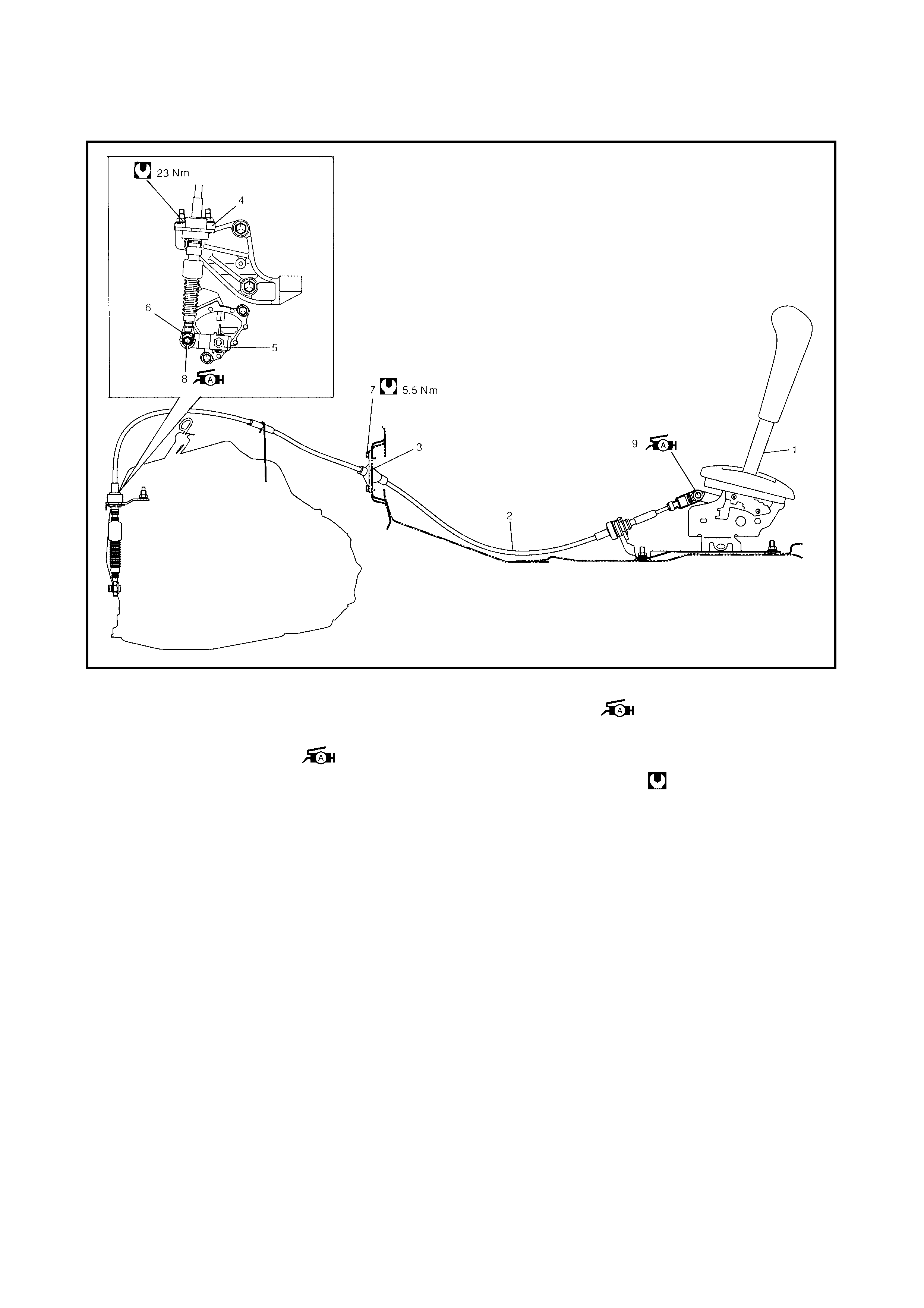
3.3 SELECT CABLE
Legend
REMOVAL
1. Remove the parking brake lever cover.
2. Remove the console box.
3. Disconnect the select cable from the selector lever and
then detach from the bracket.
4. Remove the clip and disconnect the select cable from
the manual select lever.
5. Remove the select cable retainer from the dash panel.
INSTALLATION
Install the select cable by reversing the removal procedure.
The import ant steps in the installation are as follows.
• Apply grease to the pin and cable joint.
• Tighten bolts to specified torque.
• Adjusting procedure is as follows:
1. Selector lever assembly 6. Clip 9. Selector lever pin
2. Select cable 7. Select cable retainer bolt : Apply lithium grease
3. Select cable retainer 8. Manual select lever pin
: Apply lithium grease all
around pin (0.15 g)
all around pin (0.15 g)
4. Cable bracket Tightening torque
5. Manual select lever
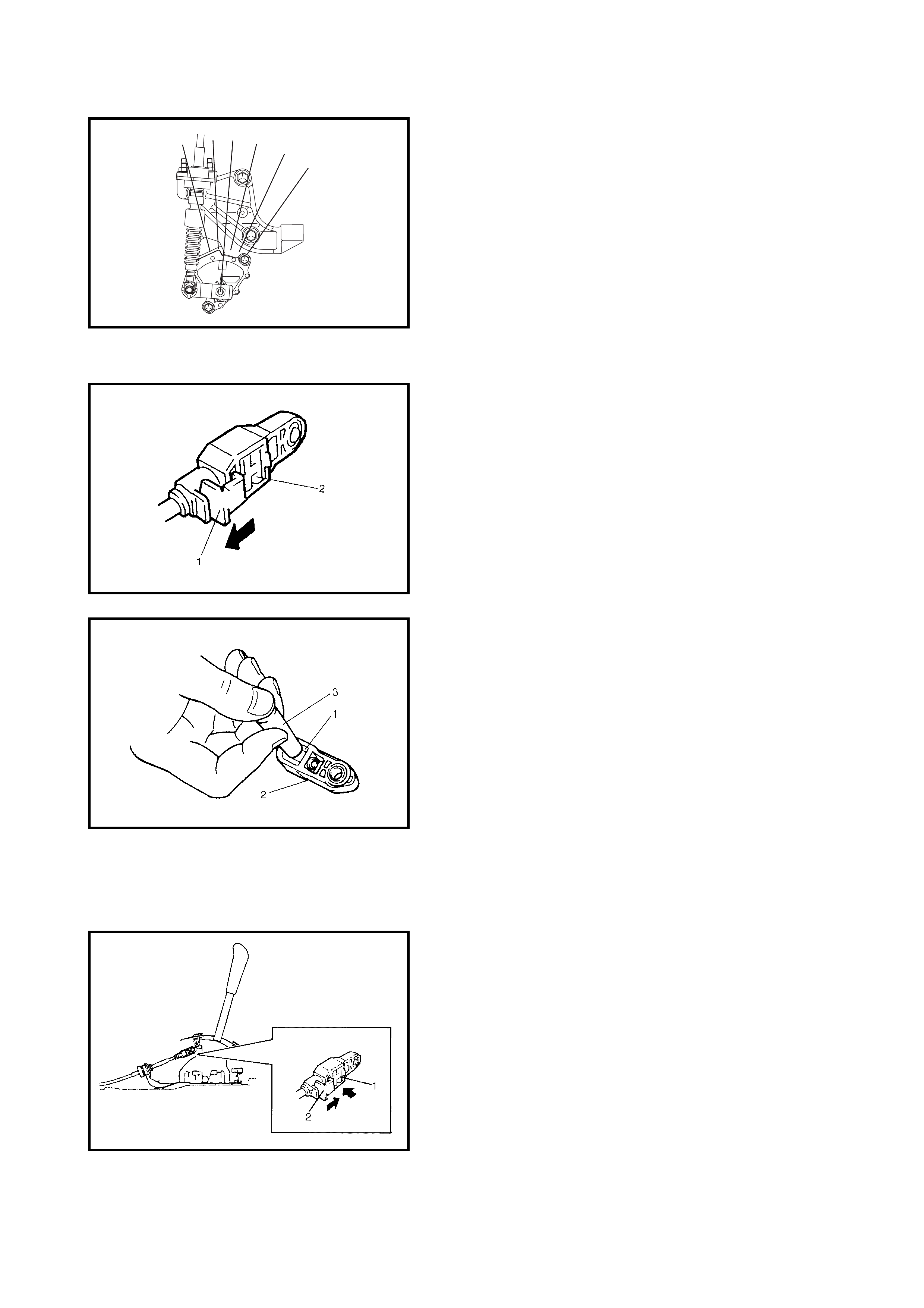
ADJUSTMENT
1. Shift the manual shift lever to N range (transmission
range sensor N range).
2. Remove the adjuster (cable end) from the selector
lever pin of the selector lever assembly.
3. Release the lock plate (1) which restricts the
movement of the cable end holder (2).
4) Push the cable end holder (1) out from the eye-end
(2) using an appropriate tool (3) to disengage
cable.
5. Shift the selector lever to N position.
6. Apply grease to the selector lever pin and install
adjuster (cable end) to it.
Lithium grease
7. With both the selector lever and the transmission range
sensor kept at N position, drive the cable end holder
(1) in until it locks the cable.
8. Slide the lock plate (2) to secure the cable end holder
in position .
9. After the select cable is installed, che ck for the follow-
ing.
10. Push vehicle with selector lever shifted to P range.
• Vehicle should not move.
• Vehicle cannot be driven in N range.
• Vehicle can be driven in D, 2 and L ranges.
• Vehicle can be backed in R range.
“P” “R” “N” “D” “2” “L”
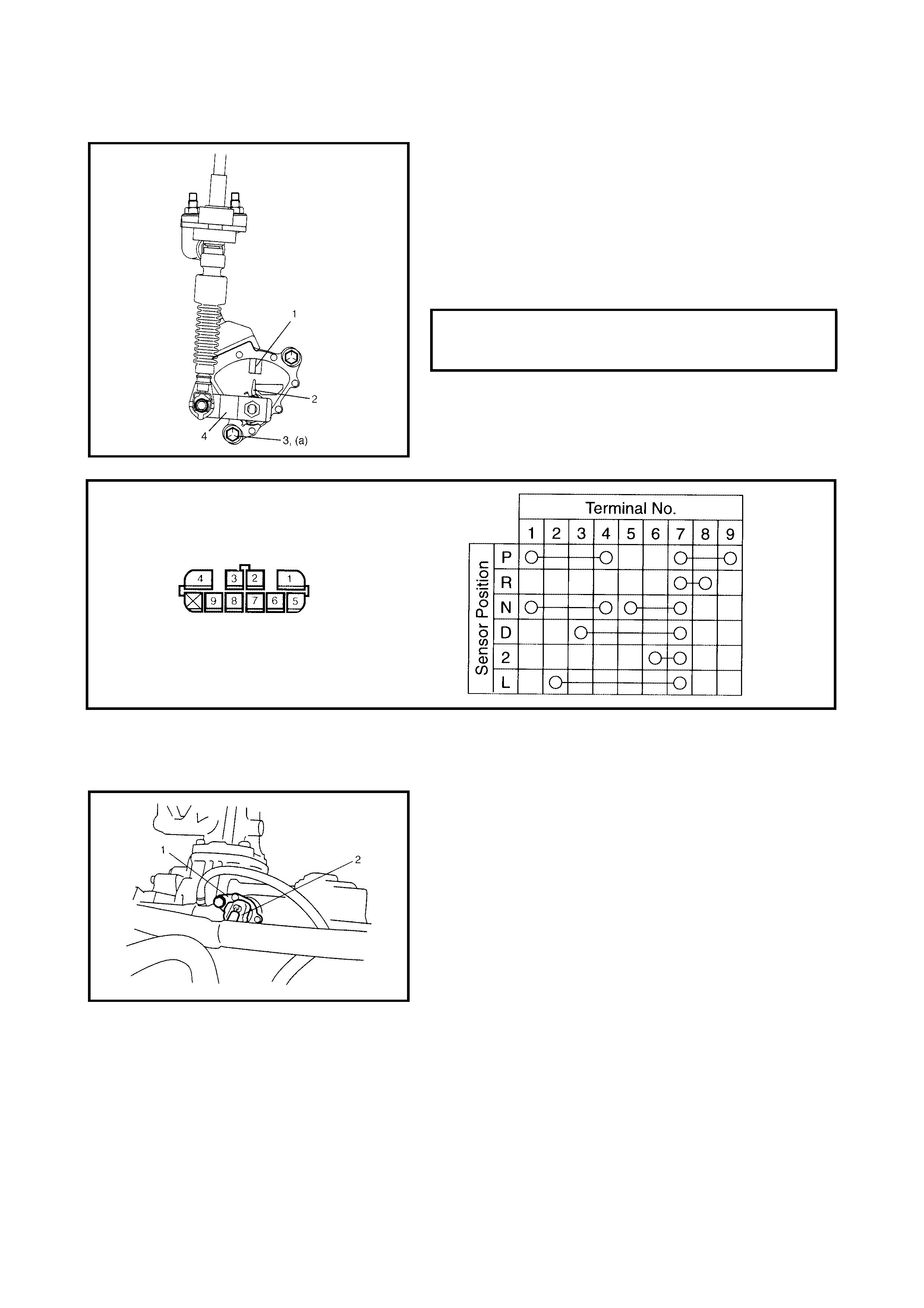
3.4 TRANSMISSION RANGE SENSOR (SHIFT SWITCH)
ADJUSTMENT AND INSPECTION
1. Shift the manual select lever (4) to N range.
2. Check that the needle direction shaped on the lock
washer (2) and N reference line (1) on the transmission
range sensor are aligned. If not, loosen sensor bolts
(3) and align them.
3. Check that the engine starts in N and P ranges but it
does not start in D, 2, L or R range. Also, check that
the back-up lamp lights in R range.
If the fault cannot be corrected by adjustment, disconnect
the transmission range sensor connector and check that
continuity exists as shown by moving manual select lever.
3.5 OUTPUT SHAFT SPEED SENSOR (VSS)
REMOVAL
1. Disconnect the negative cable at the battery.
2. Disconnect the output shaft speed sensor connector
(2).
3. Remove the output shaft speed sensor (VSS) (1) by
removing its bolt.
TRANSMISSION RANGE SENSOR
BOLTS (a)
TORQUE SPECIFICATION 5.5 Nm
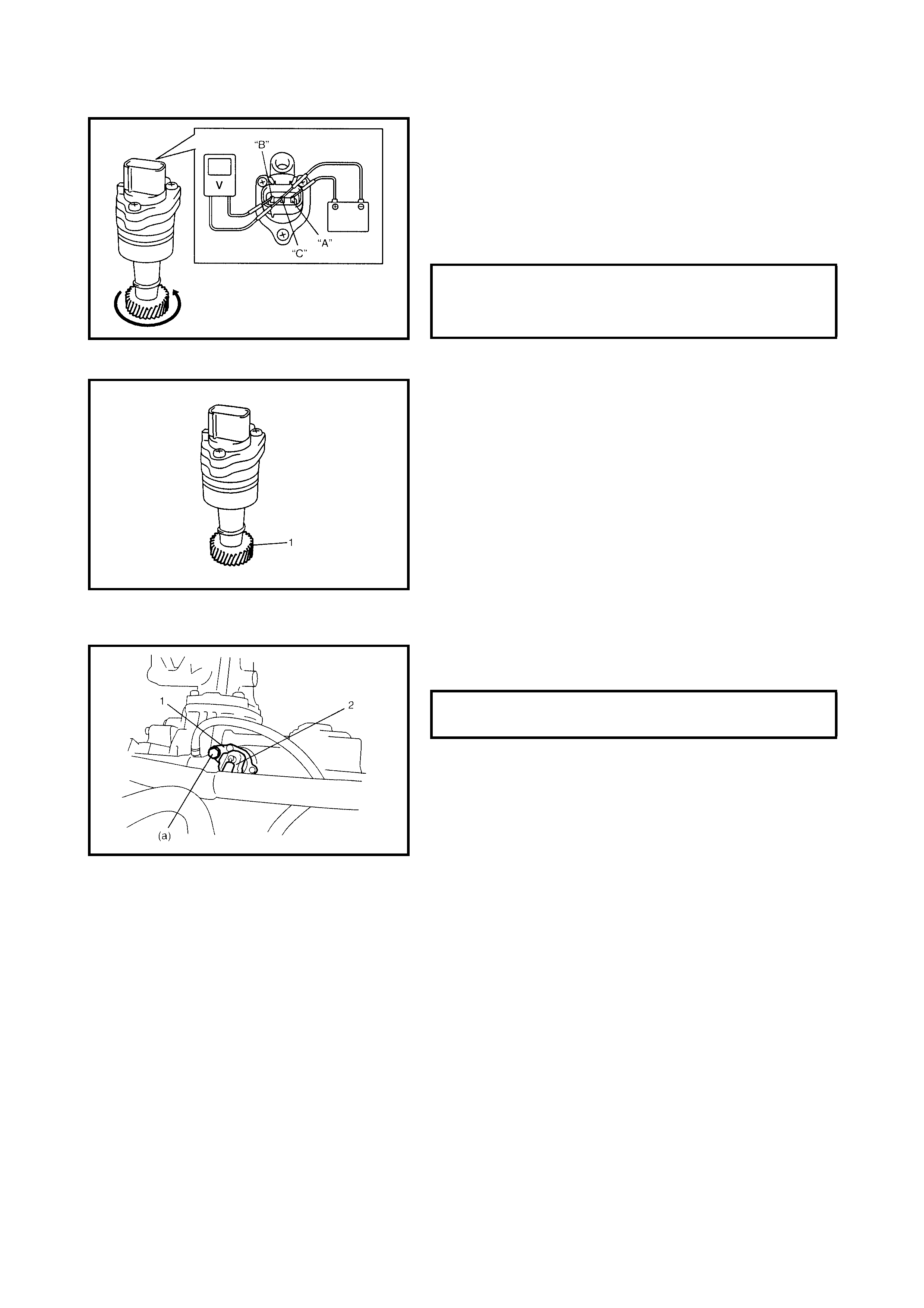
INSPECTION
1. Connect the positive cable of a 12 volt battery to the
“A” terminal of the sensor and the ground cable to the
“C” terminal. Using a voltmeter, check the voltage
between “B” terminal and “C” terminal with the output
shaft speed sensor (VSS) driven gear rotated.
If the measured voltage (pulse signal) is not as speci-
fi ed, replace sensor.
2. Check output shaft speed sensor (VSS) driven gear (1)
for wear.
Replace if necessary.
INSTALLATION
1. Apply A/T fluid to the output shaft speed sensor O-ring.
2. Install the output shaft speed sensor (VSS) (1) to the A/
T case and tighten bolt to specified torque.)
3. Connect the output shaft speed sensor connector (2) to
the output shaft speed sensor (1).
4. Connect the negative cable to the battery.
OUTPUT SHAFT SPEED SENSOR
(VSS) OUTPUT VOLTAGE PULSE SIGNAL
ALTERNATIING
BETWEEN 0 - 1 V
& 10 - 14 V
OUTPUT SHAFT SENSOR (VSS) BOLT (a)
TORQUE SPECIFICATION 13 Nm
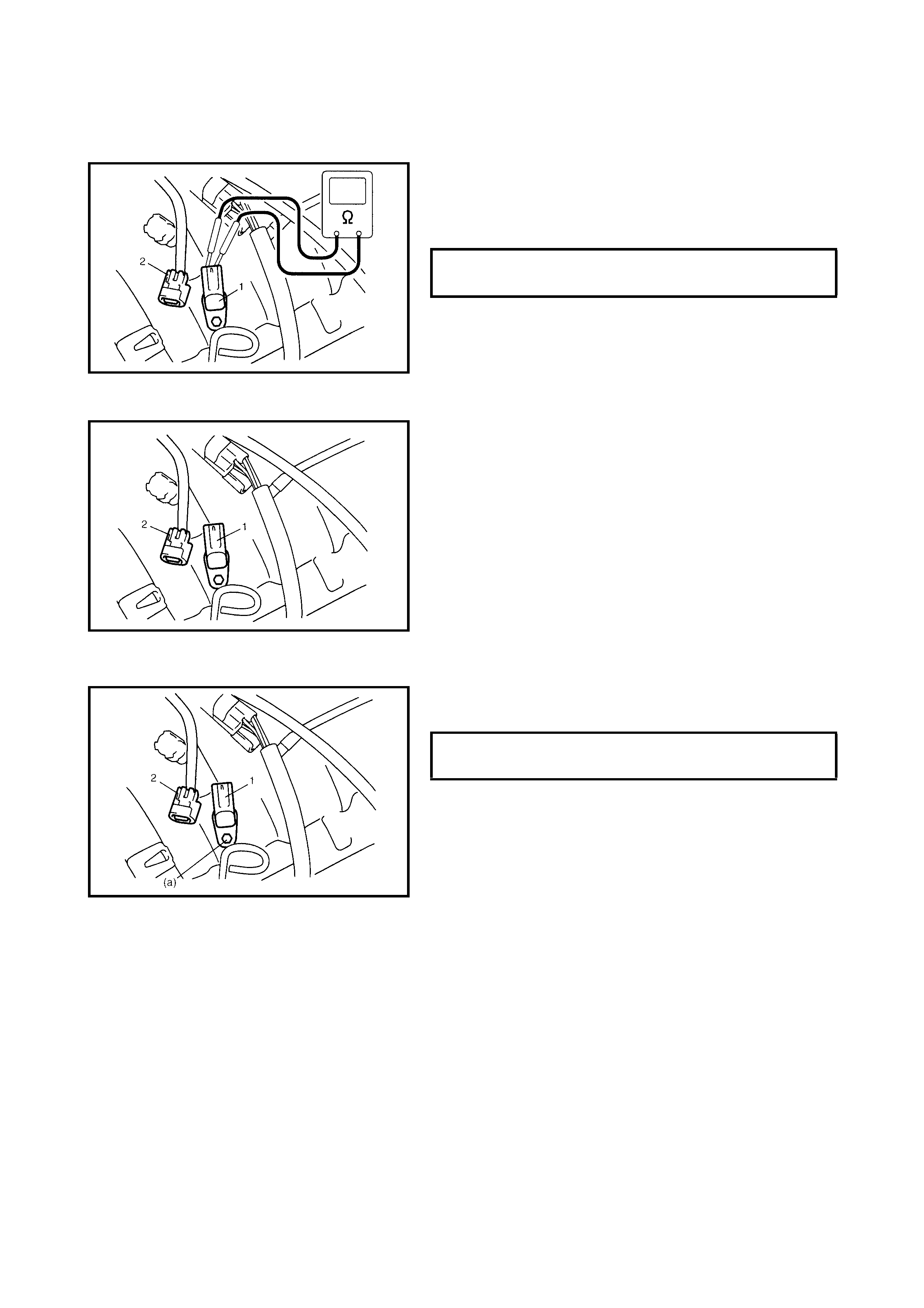
3.6 INPUT SHAFT SPEE D SENSOR
INSPECTION
1. Disconnect negative cable at battery.
2. Disconne ct the input shaft spe ed sensor conne ctor (2)
from the speed sensor (1).
3. Check the resistance between the input shaft speed
sensor terminals.
REMOVAL
1. Disconnect the negative cable at the battery.
2. Disconnect the input shaft speed sensor connector (2).
3. Remove the input shaft speed sensor (1) by removing
its bolt.
INSTALLATION
1. Apply A/T fluid to the input shaft speed sensor O-ring.
2. Install the inpu t shaft speed se nsor (1) to the A/ T case
and tighten the bolt to specified torque.
3. Connect input shaft speed sensor connector (2) to
input shaft speed sensor (1).
4. Connect the negative cable to the battery.
3.7 THROTTLE POSITION SENSOR
INSPECTION
Check the throttle position sensor, refer to Section 6E1,
2.3 ELECTRONIC CONTROL SYSTEM.
3.8 ENGINE COOLANT TEMPERATURE SENSOR
INSPECTION
Check engine cool ant temperature sensor refer to
Section 6E1, 2.3 ELECTRONIC CONTROL SYSTEM.
INPUT SHAFT SPEED SENSOR
RESISTANCE 560 - 690
Ω
@ 20°C
INPUT SHAFT SENSOR BOLT (a)
TORQUE SPECIFICATION 5.5 Nm
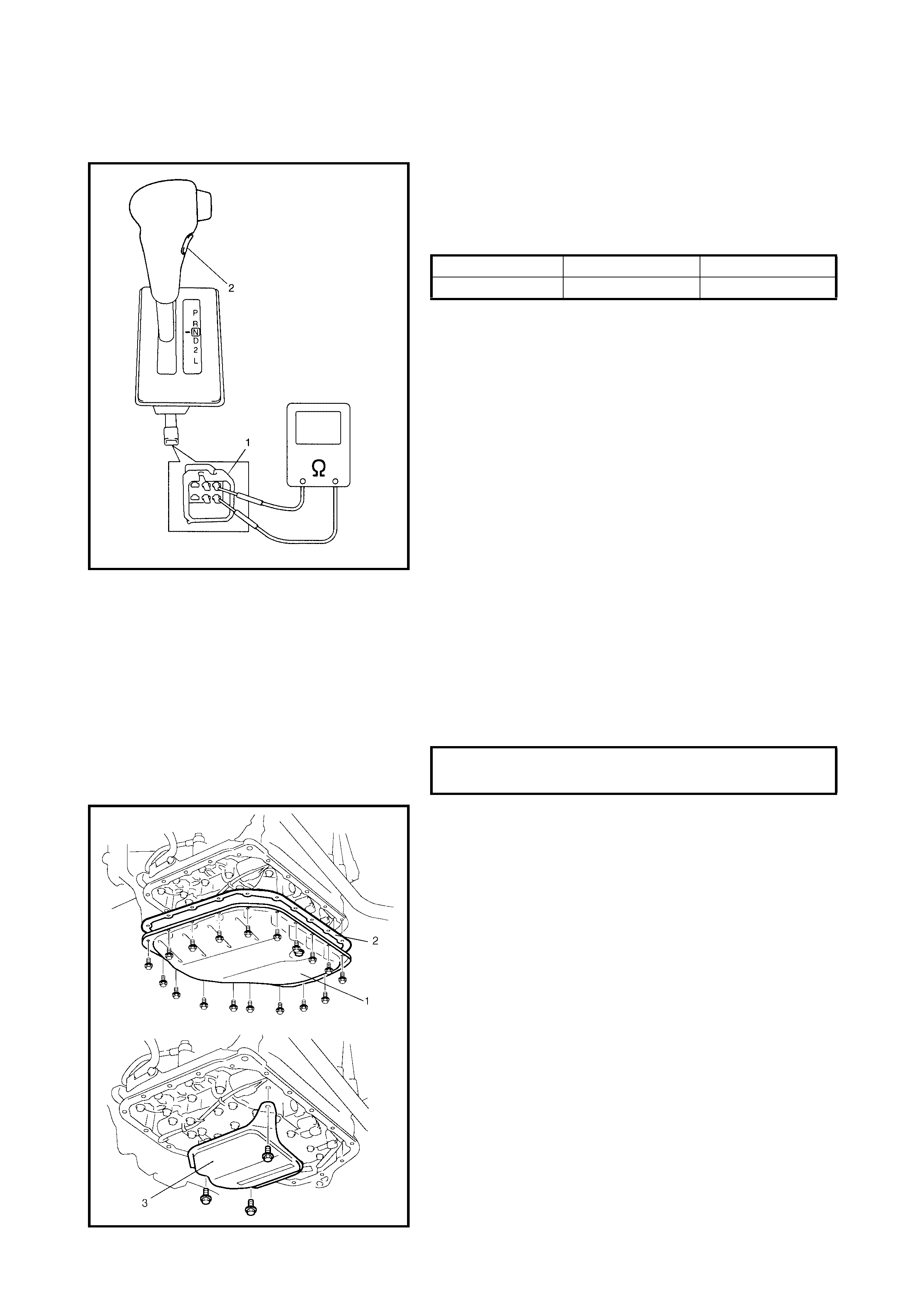
3.9 O/D OFF SWITCH
INSPECTION
1. Remove console box.
2. Disconne ct the O /D O FF sw itch connecto r (1) fr om th e
O/D switch (2).
3. Check the conti nuity between the O /D OFF switch ter-
minals.
3.10 SOLENOID VALVES (SHIFT SOLENOID VALVES, TCC SOLENOID VALVE AND
TIMING SOLENOID VALVE)
REMOVAL
1. Disconnect the negative cable at the battery.
2. Raise the vehicle on a hoist.
3. Remove the drain plug and drain A/T fluid.
4. Install the drain plug.
5. Remove the A/T oil pan (1) and oil pan gasket (2).
6. Remove the oil strainer assembly (3).
O/D off switch HELD IN RELEASED
Continuity Continuity No continuity
A/T FLUID DRAIN PLUG
SPECIFIED TORQUE 17 Nm
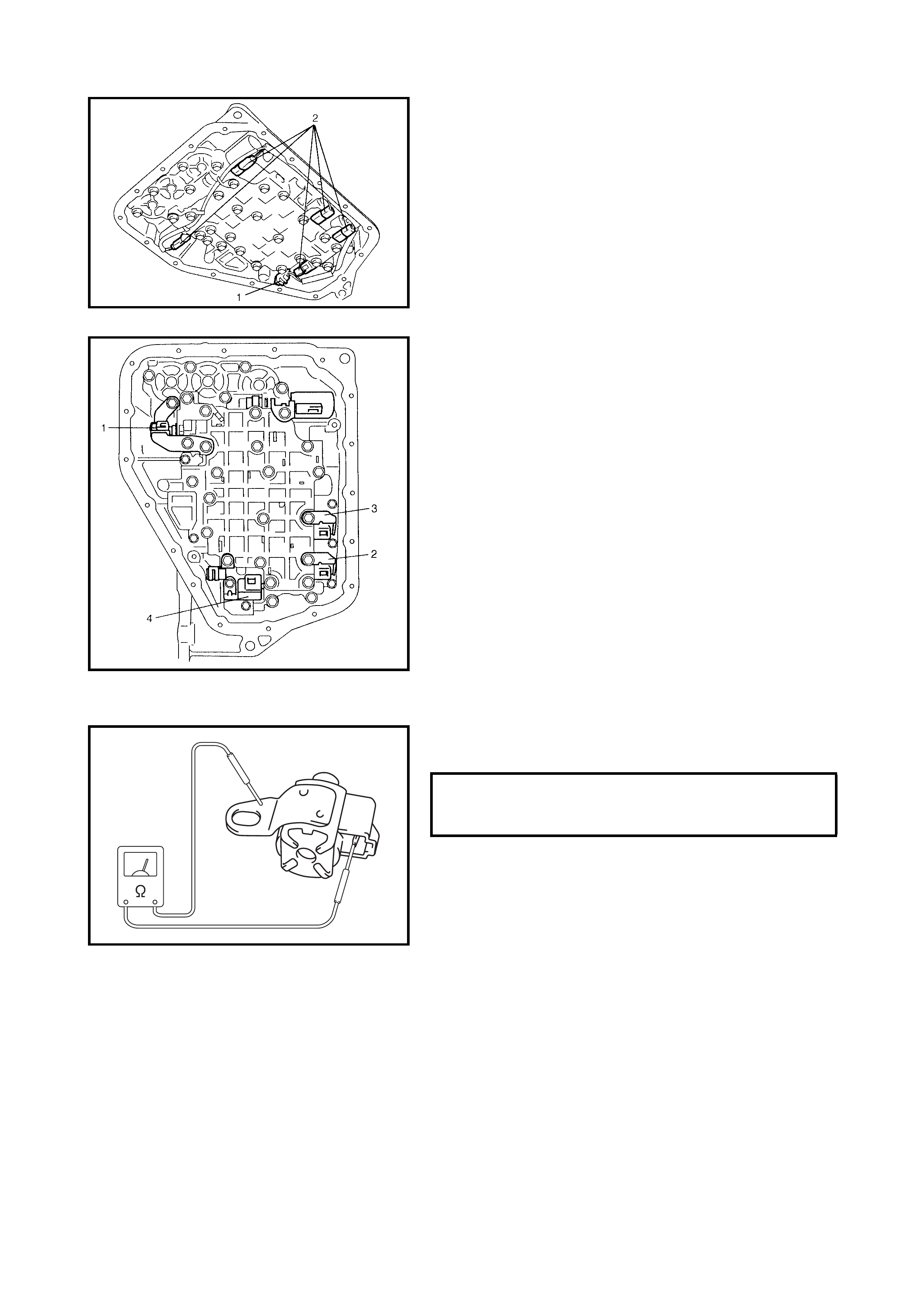
7. Remove the transmission fluid temperature sensor (1)
from the sensor clamp.
8. Disconnect the solenoid connectors (2).
9. Remove the TCC solenoid valve (1), shift solenoid
valve-A (No.1) (2), shift solenoid valve-B (No.2) (3) and
timing solenoid valve (4) by removing their bolts.
INSPECTION
Resistance Check
Shift solenoid valves, Timing solenoid valve and
Transmission Resistance at 20°C.
SHIFT SOLENOID VALVE RESISTANCE
STANDARD 11 - 15
Ω
@ 20°C
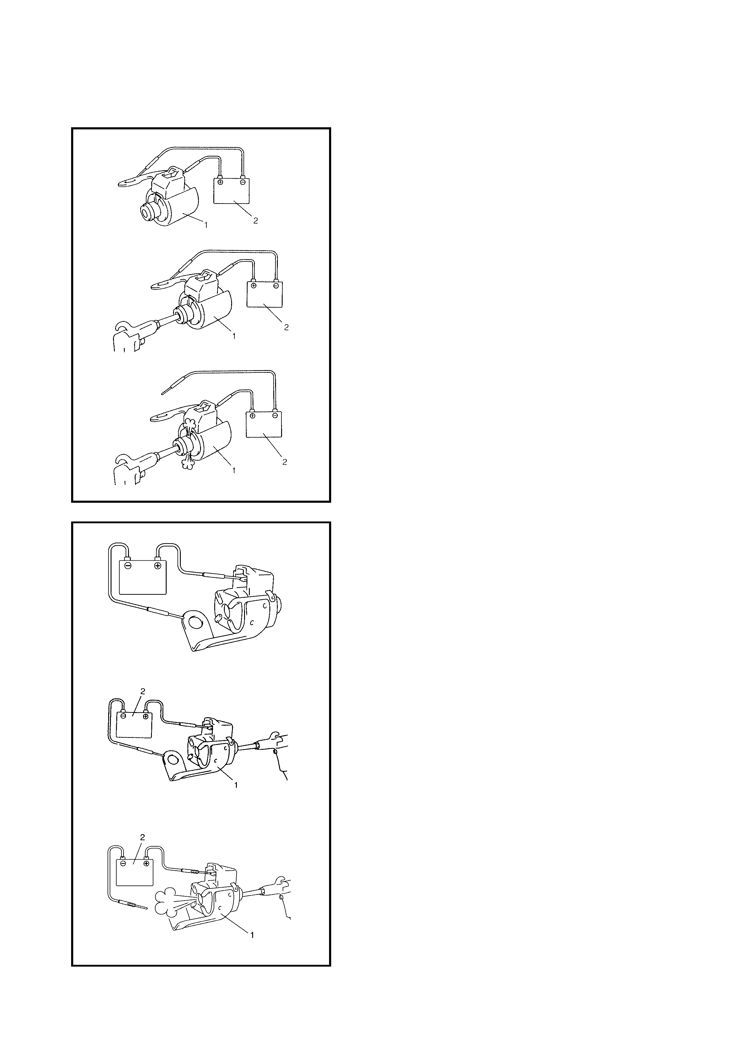
OPERATION CHECK
Shift Solenoid Valve-A (No.1), -B (No.2) And TCC
Solenoid Valve (Denso Type)
CAUTION: To avoid damage when blowing air into the
solenoid valve, do not insert the air gun against the
strainer on the inlet of the solenoid valve too deeply.
• C heck that th e sole noid v alve (1 ) actuat es with a click-
ing sound when battery voltage is applied.
• When t h e so le noi d va lv e ( 1) i s c on n ec t ed to t h e ba tt er y
(2), confirm that the solenoid valve is in a closed condi-
tion by blowing air (50 – 200 kpa) into the solenoid
valve as shown in the figure.
• When the solenoid valve (1) is not connected to the
battery (2), confirm that the solenoid valve is in an
open condition by blowing air (50 – 200 kpa) into the
solenoid valve as shown in the figure.
NOTE: Complete air test as described above to prevent
misdiagnosis as return spring is not installed in solenoid
valve.
Shift Solenoid Valve-A (No.1), -B (No.2) And TCC
Solenoid Valve (Aisin Type)
CAUTION: To avoid damage when blowing air into the
solenoid valve, do not insert the air gun against the
strainer on the inlet of the solenoid valve too deeply.
• C heck that th e sole noid v alve (1 ) actuat es with a click-
ing sound when battery voltage is applied.
• When t h e so le noi d va lv e ( 1) i s c on n ec t ed to t h e ba tt er y
(2), confirm that the solenoid valve is in a closed condi-
tion by blowing air (50 – 200 kpa) into the solenoid
valve as shown in the figure.
• When the solenoid valve (1) is not connected to the
battery (2), confirm that the solenoid valve is in an
open condition by blowing air (50 – 200 kpa) into the
solenoid valve as shown in the figure.
NOTE: Complete air test as described above to prevent
misdiagnosis as return spring is not installed in the solenoid
valve.
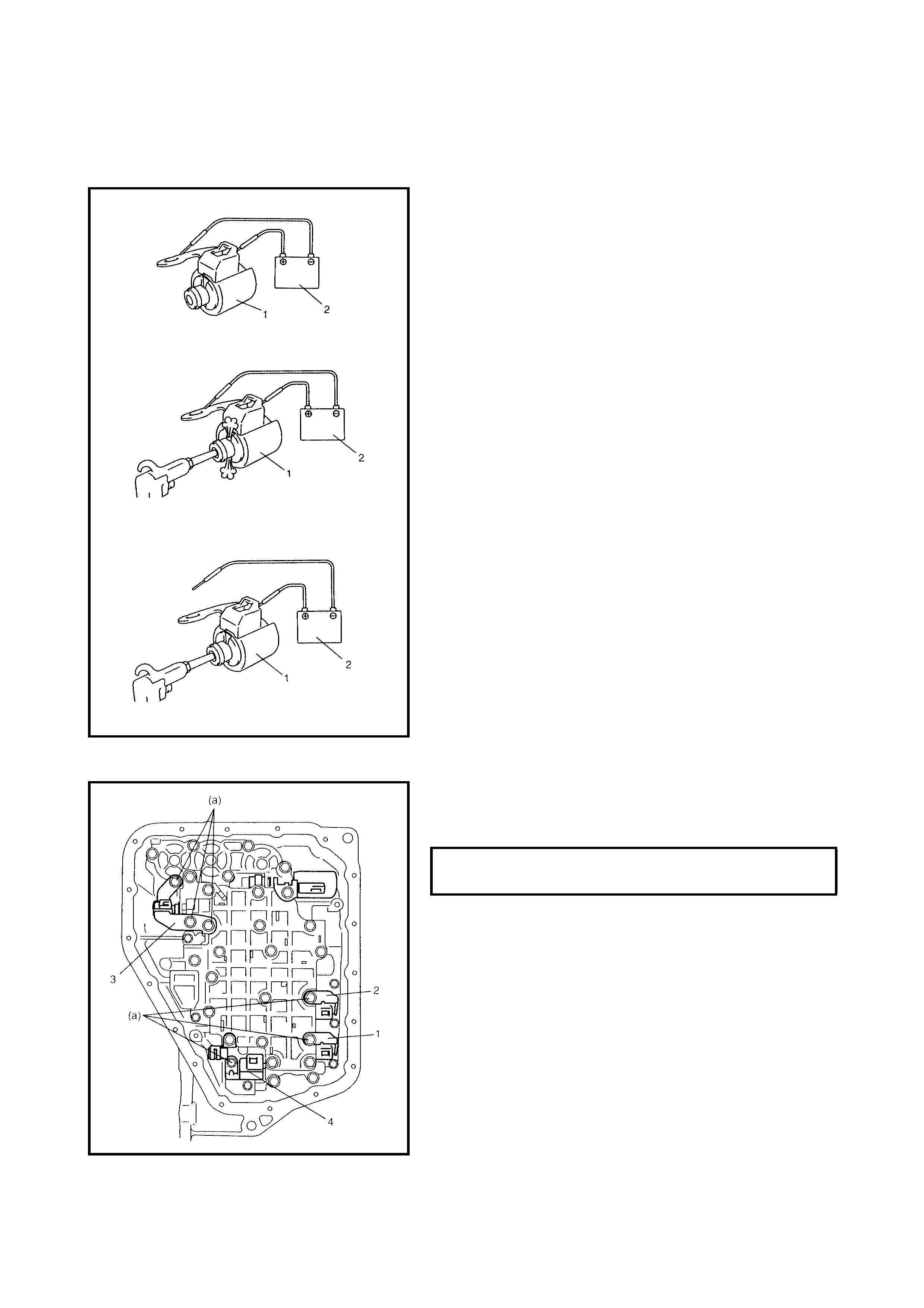
TIMING SOLENOID VALVE (BOTH DENSO AND AISIN TYPE)
CAUTION: To avoid damage when blowing air into the
solenoid valve, do not insert the air gun against the
strainer on the inlet of the solenoid valve too deeply.
• Check that solenoid valve (1) actuate with a clicking
sound when battery voltage is applied.
• Wh en the timing sol enoid valve ( 1) is conne cted to the
battery (2), confirm that the timing solenoid valve is in
an open condition by blowing air (50 – 200 kpa) into
the solenoid valve as shown in the figure.
• Wh en the timing sol enoid va lve ( 1) is not conn ected to
the battery (2), confirm that the timing solenoid valve is
in a closed condition by blowing ai r (50 – 200 kpa) into
the solenoid valve as shown in the figure.
NOTE: Complete air test as described above to prevent
misdiagnosis as return spring is not installed in the solenoid
valve.
INSTALLATION
1. Install the shift solenoid valve-A (No.1) (1), shift
solenoid valve-B (No.2) (2), TCC solenoid valve (3)
and the timing solenoid valve (4).
SOLENOID VALVE BOLTS (a)
TORQUE SPECIFICATION 11 Nm
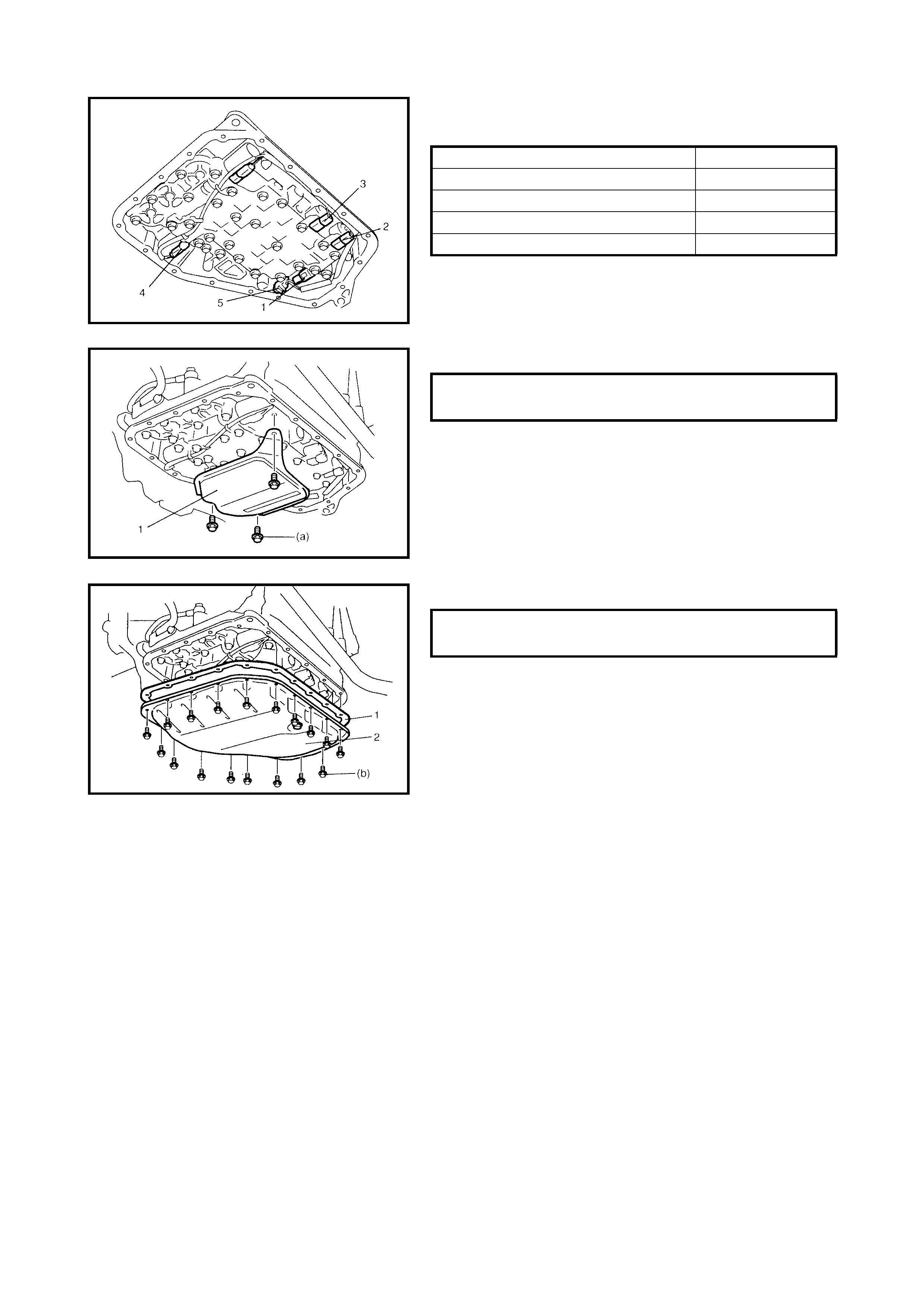
2. Connect the solenoid connectors identifying their
installation positions by wire colour.
3. Install the transmission flu id temperature sensor (5) to
the sensor clamp.
4. Install the oil strainer assembly (1).
5. Install new oil pan gasket (1) and oil pan (2).
Solenoid connector Wire colour
Shift solenoid valve-A (No.1) (2) White
Shift solenoid valve-B (No.2) (3) Black
Timing solenoid valve (1) Yellow
TCC solenoid valve (4) Light Green
OIL STRAINER BOLTS (a)
TORQUE SPECIFICATION 10 Nm
OIL PAN BOLTS (b)
TORQUE SPECIFICATION 7.0 Nm
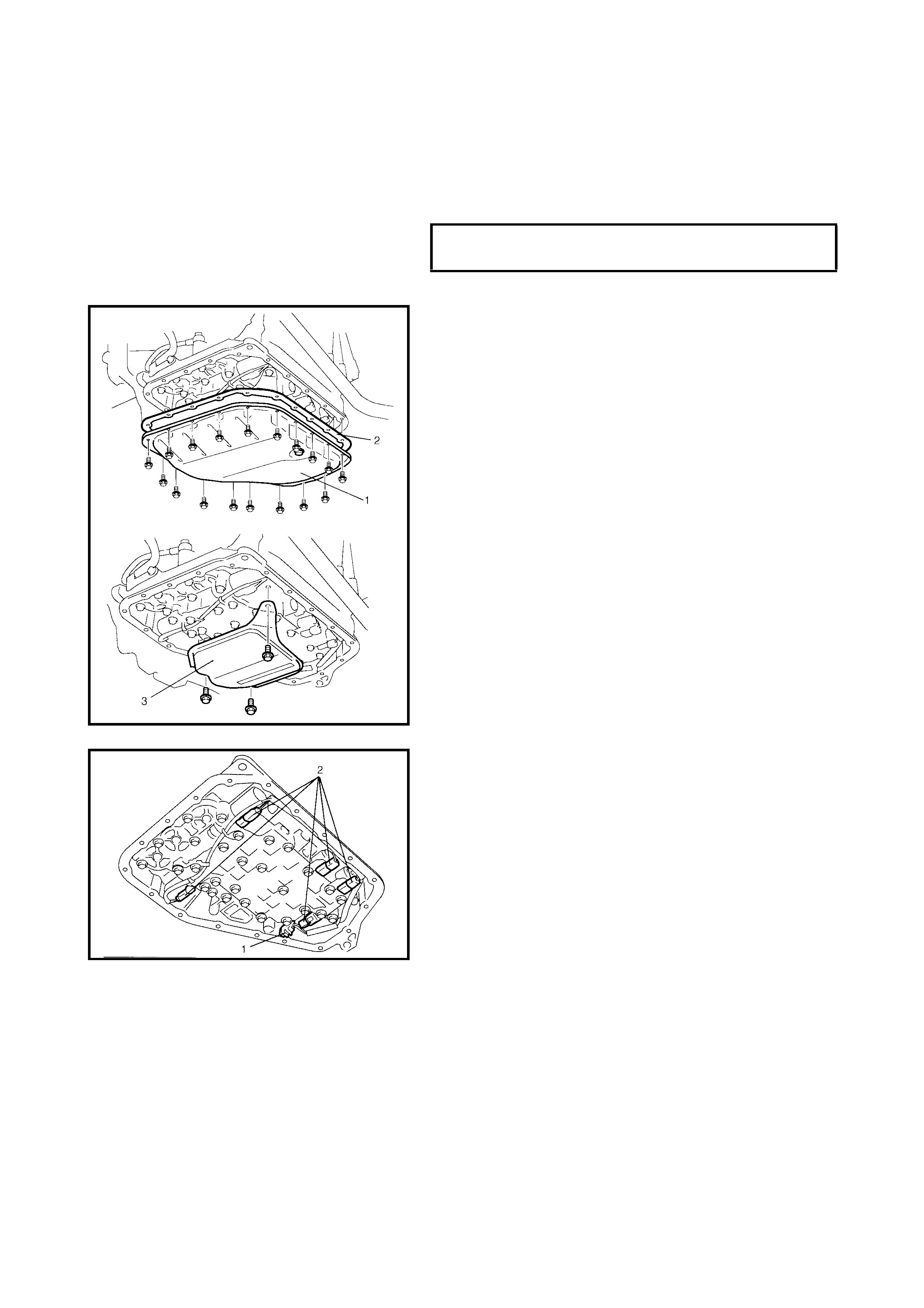
3.11 PRESSURE CONTROL SOLE NOID VALVE
REMOVAL
1. Disconnect the negative cable at the battery.
2. Raise the vehicle on a hoist.
3. Remove the drain plug and drain the A/T fluid.
4. Install the drain plug.
5. Remove the A/T oil pan (1) and the oil pan gasket (2).
6. Remove the oil strainer assembly (3).
7. Remove the transmission fluid temperature sensor (1)
from the sensor clamp.
8. Disconnect the solenoid connectors (2).
9. Remove the valve body assembly, refer to
4.5 UNIT DISASSEMBLY in this Section.
10. Remove the pressure control solenoid valve, refer to
VALVE BODY in 4.5 DIFFERENTIAL ASSEMBLY in
this Section.
A/T FLUID DRAIN PLUG
TORQUE SPECIFICATION 17 Nm
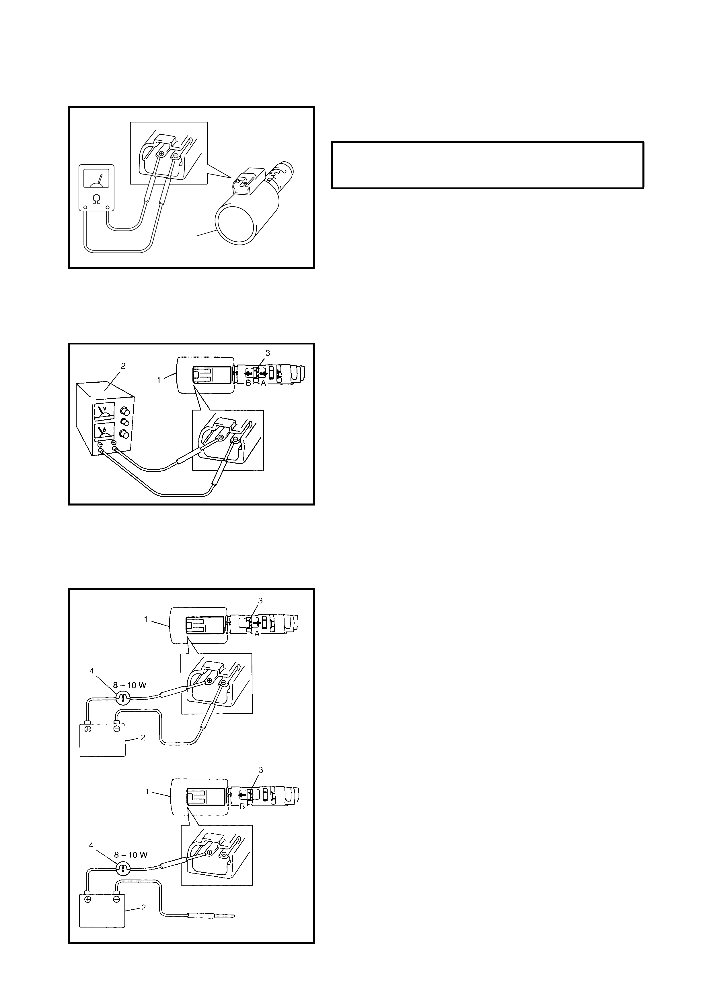
INSPECTION
Resistance Check
Measur e th e res i stance be twee n the press ur e c on tro l so le-
noid valve (1) terminals.
Operati on Check
Check the pressure con trol solenoid v alve operatio n in the
following manner:
[Using regulated DC power supply]
1. Connect the pressure control solenoid valve (1) to a
regulated DC power supply (2) as shown in the figure.
2. Turn the regulated DC power supply switch ON,
increase the voltage of the power supply keeping the
current within 1.0 A.
3. Check for gradual movement of valve (3) in the
direction of arrow “A” as the voltage is increased.
4. Check for movement of valve (3) in the direction of
arrow “B” as the voltage is decreased.
5. Turn the power supply switch OFF.
CAUTION: Do not pass a current of 1.0 A or more
through the pressure control solenoid or it may burn
out.
[Not using regulated DC power supply]
6. Connect the pressure control solenoid valve (1) to a
battery (2) with a 8 – 10 W bulb (4) connected as
shown in the figure.
7. Check for movement of valve (3) in the direction of
arrow “A”.
8. Disconnect the pressure control solenoid valve (1)
from the battery (2) and check for movement of valve
(3) in the direction of arrow “B” as shown in the figure.
CAUTION: Connect an 8 – 10 W bulb as shown or the
pressure contr ol solenoid valve may burn out.
PRESSURE CONTROL SOLENOID
VALVE RESISTANCE STANDARD 5.0 - 5.6
Ω
@ 20°C
1
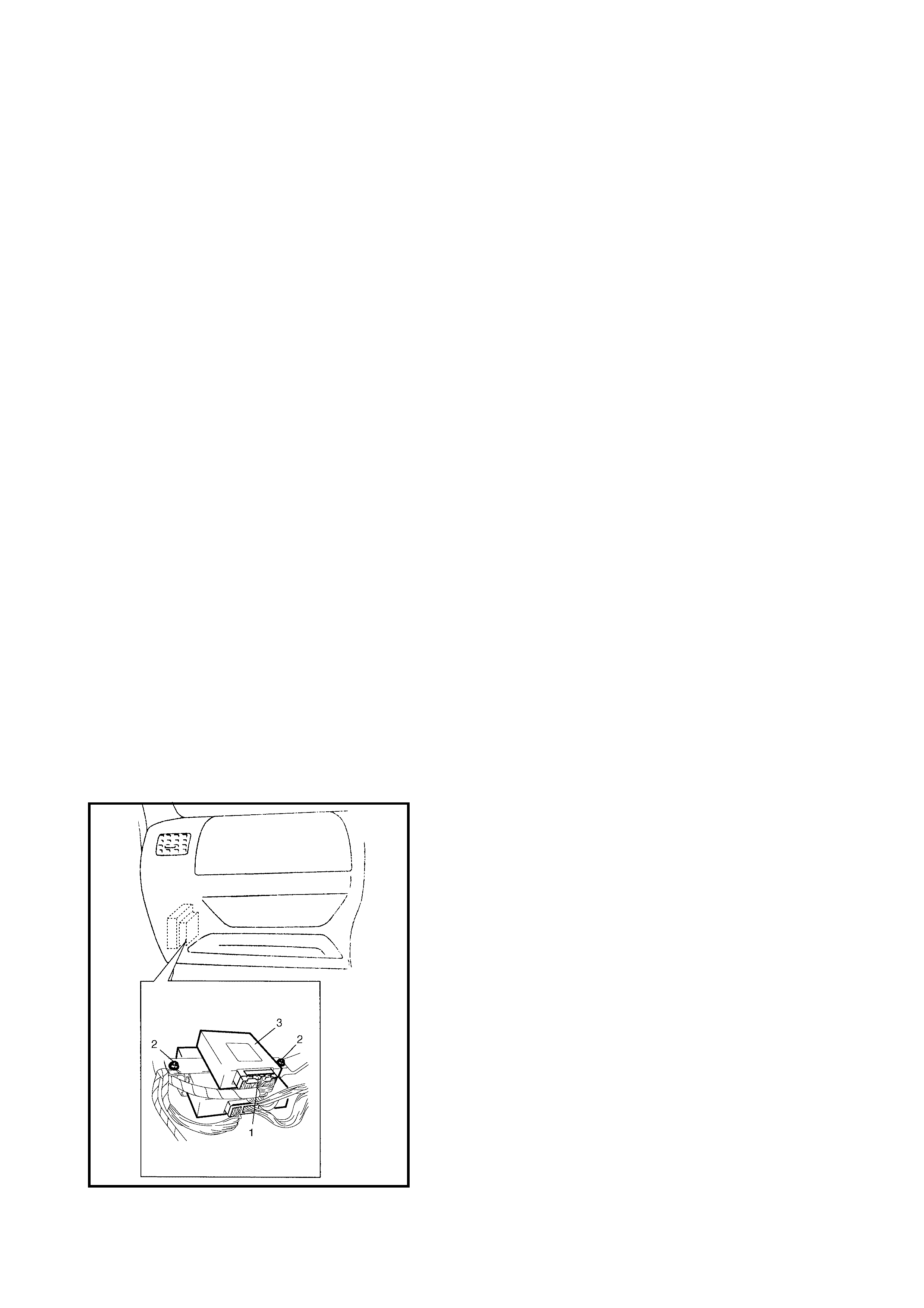
INSTALLATION
Reverse removal procedure to install the pressure control
solenoid valve and the valve body noting the following
points:
• Fo r detail o f the pressure contro l solen oid va lve ins tal-
lation, refer to VALVE BODY in
4.5 DIFFERENTIAL ASSEMBLY in this Section.
• For details of the valve body installation, refer to
4.6 UNIT ASSEMBLY in this Section.
• For details of installing the wire harness for the sole-
noid valves and sensor, refer to 4.6 UNIT ASSEMBLY
in this Sectio n. Use new O- rin gs .
• Fo r details of the A/T oil pan a nd oil strain er assembly
installation, refer to 4.6 UNIT ASSEMBLY in this
Section. Use a new oil pan gasket.
• Replenish the A/T fluid and check the fluid level
according to procedure described in FLUID CHANGE
in 3.1 MAINTENANCE SERVICE in this Section.
• Check for fluid leaks after A/T warms up.
3.12 TRANSMIS SION CONTROL MODULE (TCM)
CAUTION:
• The TCM and ECM consists of precision parts,
therefore when handling, take care not to expose it
to excessive shock.
• When replacing the TCM with a used one, all the
learned contents, which have been stored in the
TCM memory by executing learning control, should
be initialised after replacement.
REMOVAL
1. Disconnect the negative cable at the battery.
2. Disable the air bag system. Refer to DISABLING AIR
BAG SY STE M in Section 10B, 3.1 SERVICE
PRECAUTIONS.
3. Disconnect connectors (1) from the TCM.
4. Remove the nuts (2) securing the TCM (3) and remove
TCM.
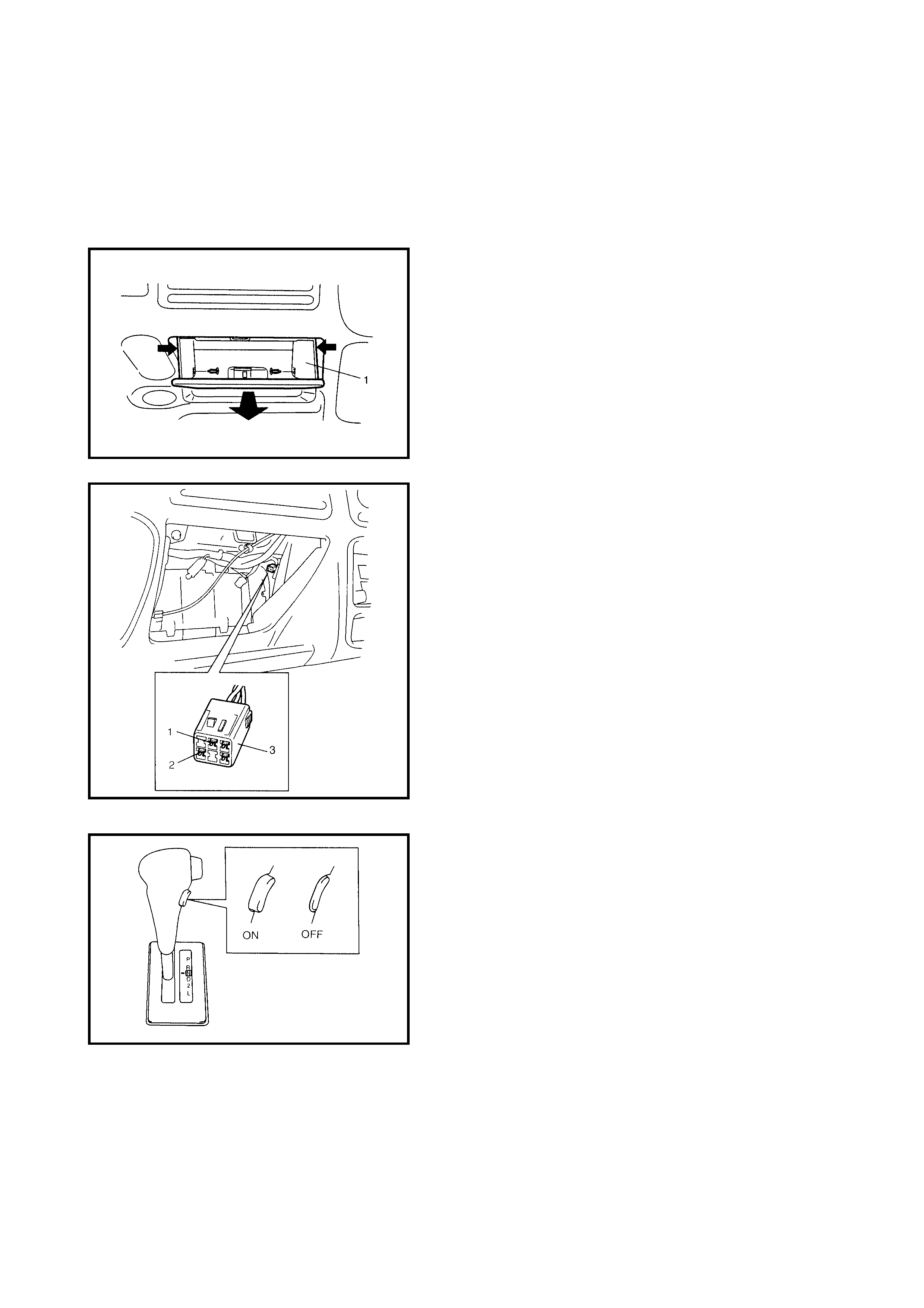
INSTALLATION
Reverse removal procedure noting the following:
• Connect the TCM connectors securely.
• Enable the air bag system after the TCM has been
refitted. Refer to ENABLING AIR BAG SYSTEM in
Section 10B, 3.1 SERVICE PRECAUTIONS.
LEARNING CONTROL INITIALISATION
1. Remove the glove box (1) from the instrument panel.
2. Using a service wire, connect the diagnosis switch
terminal (1) and the ground terminal (2) of the
diagno sis connecto r No.2 (3 ).
3. Turn the ignition switch ON leaving the engine OFF.
4. Confirm that the O/D OFF switch is OFF.
5. Shift the selector lever to L range.
6. With the br ake pedal and acceler ator peda l depresse d
fully, turn the O/D OFF switch ON and OFF 5 times
within 10 seconds to complete memory initialisation.
NOTE: When initialisation is achieved, the O/D OFF lamp
does no t light or flash u nless the diagnosi s swit ch termina l
is disconnected from the ground terminal of the diagnosis
connector No. 2. If initialisation has failed, repeat the initial-
ising procedure.
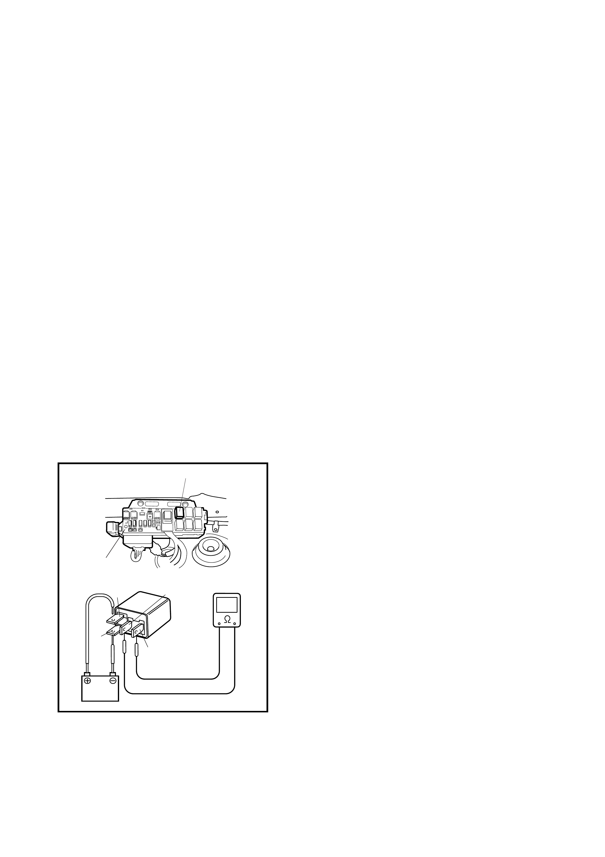
BRIEF LEARNING
This method is useful when the learned condition for the automat ic transaxle needs to be initialised quickly.
For example, when the shift shock in shifting 4th gear to 3rd becomes worse after replacing the TCM.
1. Turn the ignition switch ON, and confirm that the O/D OFF switch is OFF (the O/D OFF light in the
combination meter does not light).
2. Start the engine and raise the transaxle fluid temperature to normal operating temperature.
3. Start the vehicle and repeat the kickdown of 4th gear to 3rd gear, 10 times in each of the vehicle speed
ranges shown below.
• 27 – 35 km/h
• 35 – 58 km/h
• 58 – 81 km/h
• 81 – 104 km/h
• 104 – 126 km/h
4. Refer to 2.4 AUTOMATIC GEAR SHIFT DIAGRAM in this Section, perform upshifting of 3rd gear to 4 th
gear, 10 times in each of the throttle opening ranges shown below.
• 0 - 20 %
• 20 - 40 %
• 40 - 60 %
• 60 - 80 % (if necessary)
• 80 -100 % (if necessary)
5. At D range, perform upshifting 10 times in each of the vehicle speed ranges shown below.
• 20 - 55 km/h
• 55 - 70 km/h
• 70 - 90 km/h
• 90 - 125 km/h (if necessary)
• 125 - km/h (if necessary)
3.13 A/T RELAY
INSPECTION
1. Disconnect the negative cable at the battery.
2. Remove the A/T relay (2) from the fuse and relay box
(1).
3. Check that there is no continuity between terminal C
and D.
If the continuity is indicated, replace the A/T relay.
4. Connect the battery positive (+) terminal to terminal A
of the A/T relay and the battery negative (–) terminal to
the terminal “B” of the A/T relay.
Check the continuity between terminal C and D of the
A/T relay.
If continuity is not indicated, replace the A/T relay.
“D”
“B”
“A”“C”
2
1
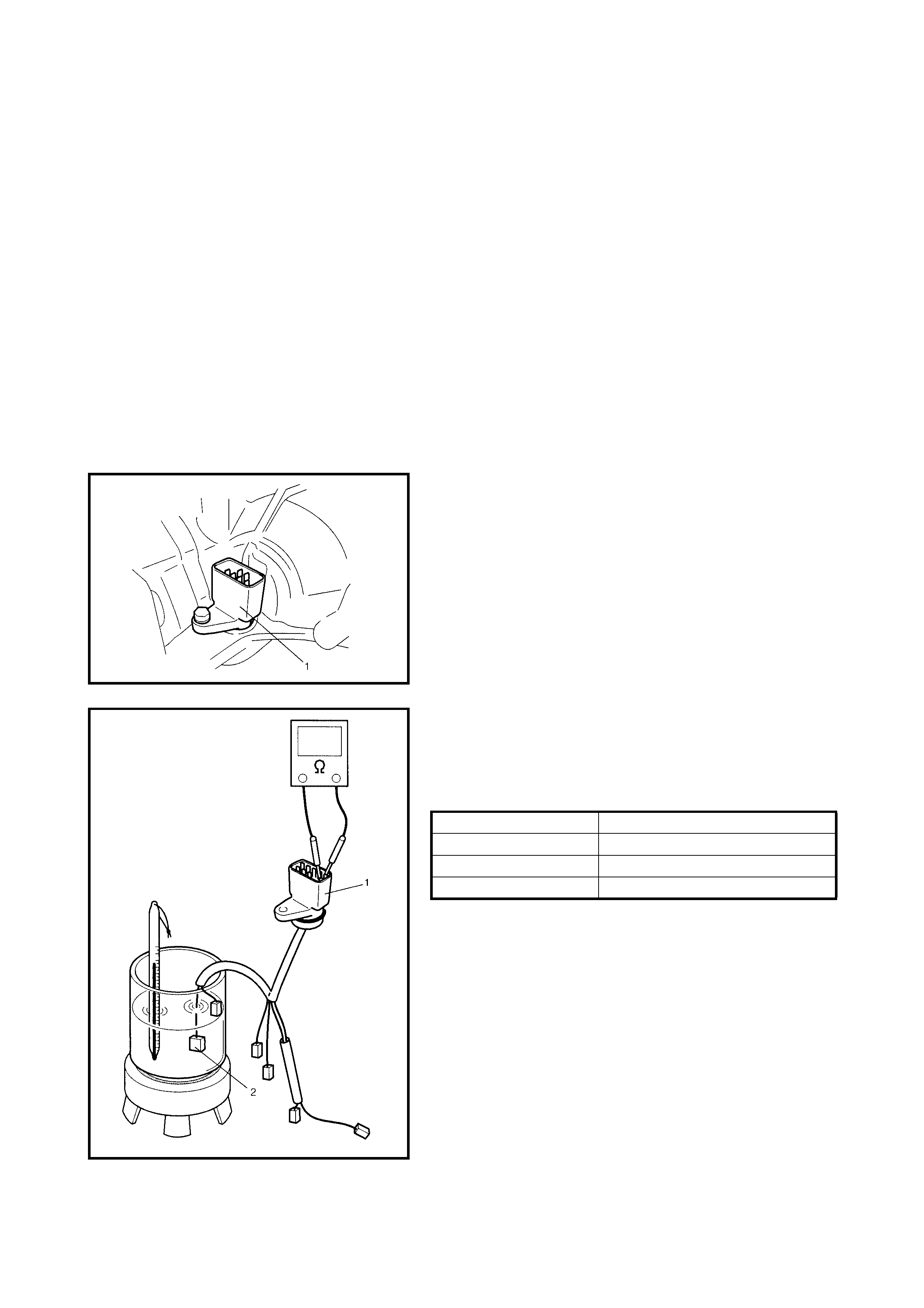
3.14 TRANSMISSION FLUID TEMPERATURE SENSOR
INSPECTION
1. Disconnect the negative cable at the battery.
2. Raise the vehicle on a hoist.
3. When the engine is cool, remove the drain plug and
drain the A/T fluid.
4. Install the drain plug.
5. Remove the A/T oil pan.
6. Remove the oil strainer assembly.
7. Remove the valve body assembly, refer to
4.3 UNIT DISASSEMBLY in this Section.
CAUTION: When removing the valve body harness
from the transaxle case, take care not to damage the
transmission fluid temperature sensor at the narrow
exit of the case.
Careless sensor treatment may cause sensor
malfunction.
8. Remove the valve body harness bolt and remove the
valve body harness.
9. Heat the transmission fluid temperature sensor (2).
Check the resistance between the terminals of the
valve body harness connector (1). Ensure its resis-
tance decreases as its temperature increases.
Transmission fluid temperature sensor resistance
Temperature Resistance
10°C 5.8 – 7.1 kΩ
110°C 231 – 263 Ω
145°C 105 – 117 Ω
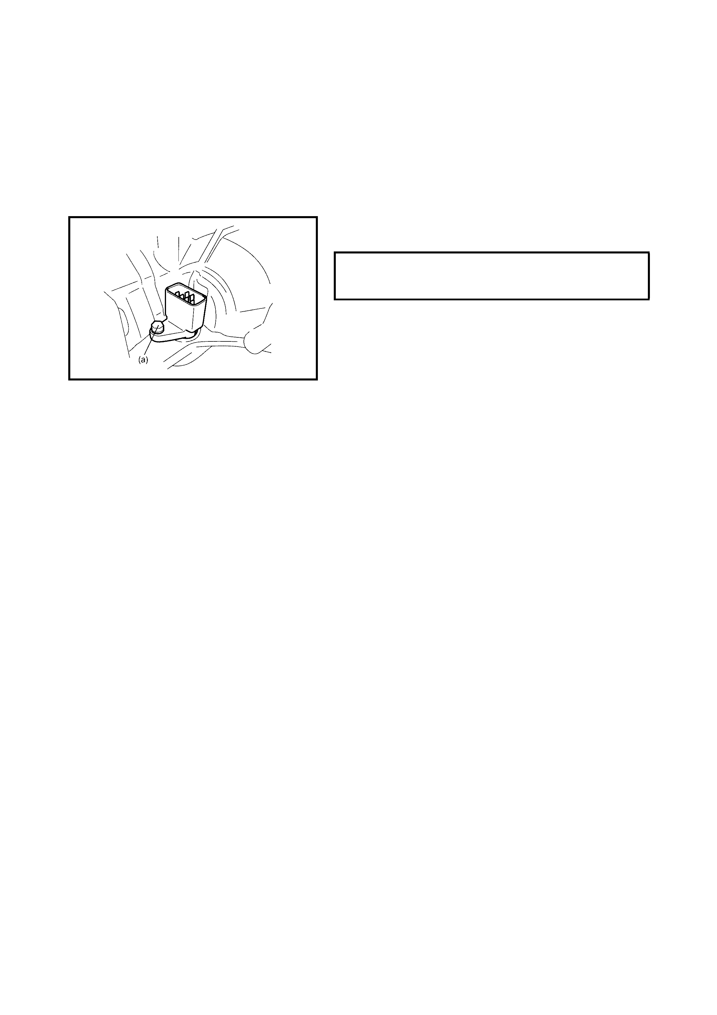
INSTALLATION
Reverse removal procedure to install the solenoid wire har-
ness and valve body noting the following points:
• For details of the valve body and their connectors
installation, refer to 4.6 UNIT ASSEMBLY in this
Section.
• For details of the A/T oil pan installation, refer to
4.6 UNIT ASSEMBLY in this Section. Use a new oil
pan gasket.
• Tighten the valve body harness connector bolt to spec-
ified torque.
• Repl enish the A/T fluid a nd check the fluid level , refer
to FLUID CHANGE in 3.1 MAINTENANCE SERVICE
in this Sectio n.
• Chec k fo r flu id le aks after the A /T ha s reac hed o perat-
ing temperature.
VALVE BODY HARNESS CONNECTOR
BOLT (a)
TORQUE SPECIFICATION 5.5 Nm
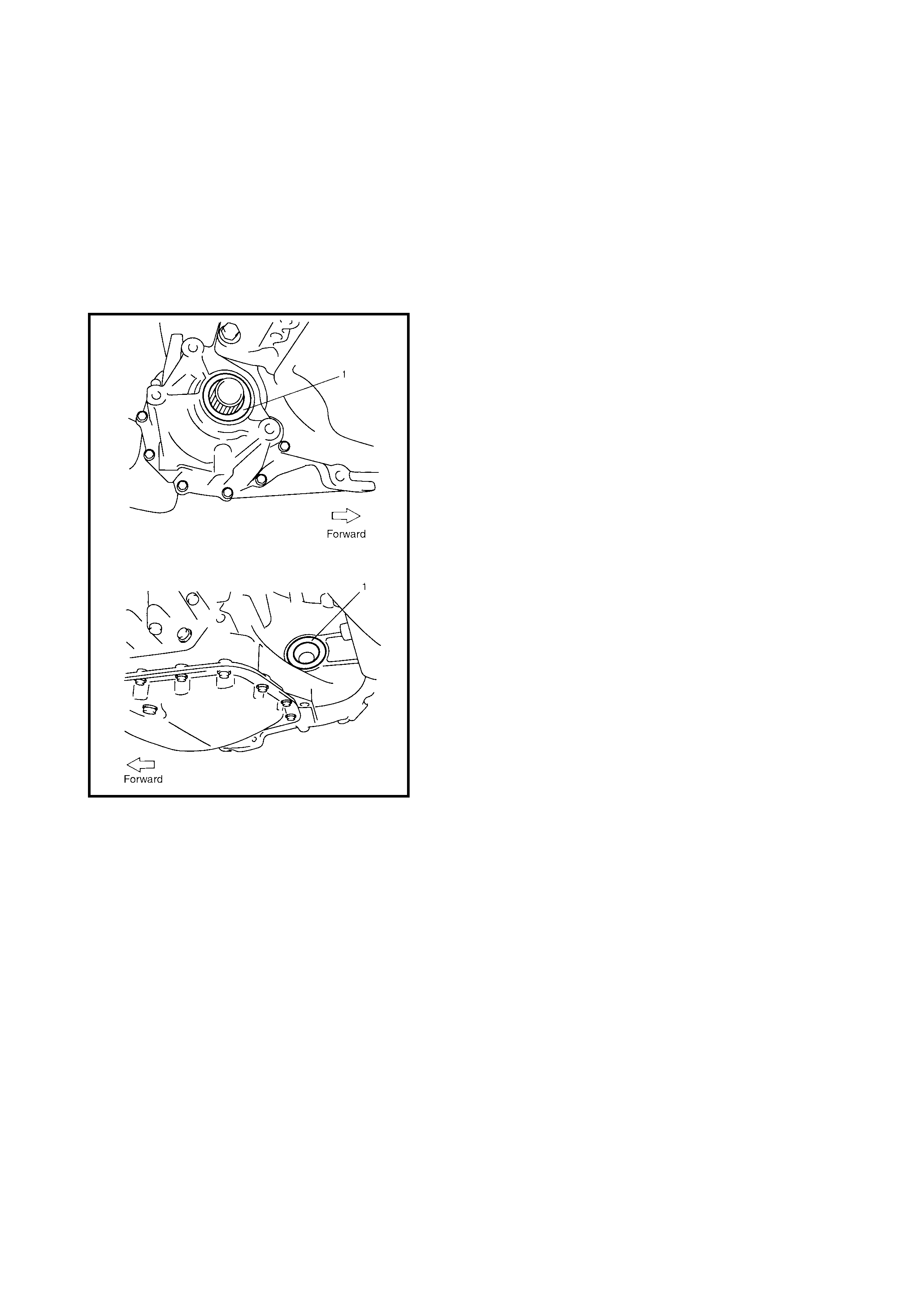
3.15 DIFFERENTIAL SIDE OIL SEAL
REPLACEMENT
1. Raise the vehicle on a hoist and drain the A/T fluid.
2. Remove the drive shaft joints from differential gear on
the transaxle, refer to Section 4A FRONT DRIVE
SHAFTS.
It is not n ecessary to remo ve the drive sha fts from the
steering knuckles to remove the differential side oil
seal.
3. Remove the transfer, refer to Section 7D TRANSFER.
4. Remove the differential side oil seal (1) using a screw
driver or similar.
5. Apply grease to the new differential side oil seal lips.
Lithium grease
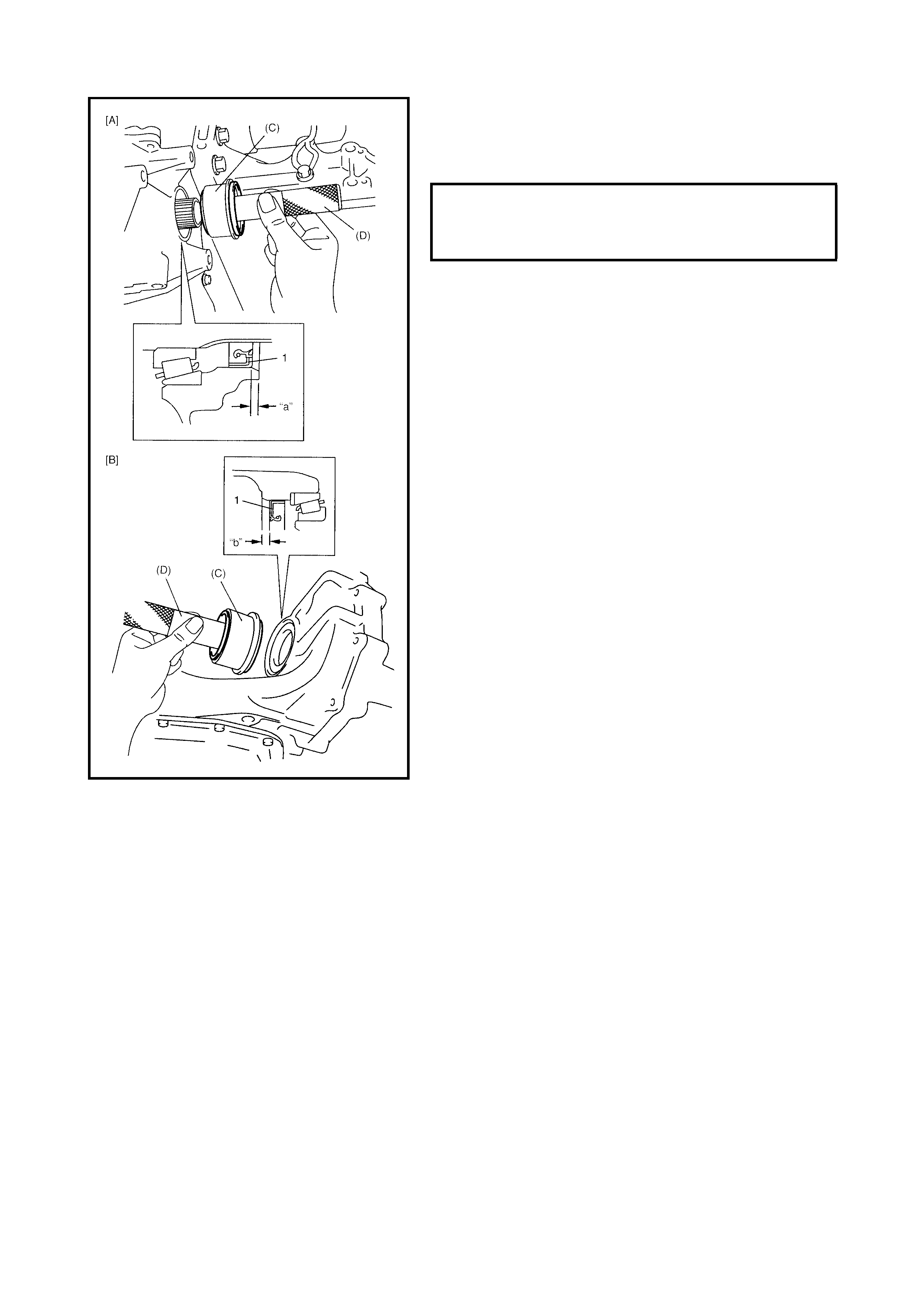
6. Install the new differential side oil seals (1) using
special tools 09944-88220 (C) and 09924-74510 (D).
[A] - Right side
[B] - Left side
7. Install the transfer, refer to Section 7D TRANSFER.
8. Install the drive shaft, refer to Section 4A FRONT
DRIVE SHAFTS.
9. Replenish the A/T fluid, refer to FLUID CHANGE in
3.1 MAINTENANCE SERVICE in this Section.
DIFFERENTIAL SIDE OIL SEAL
INSTALLING DEPTH RIGHT SIDE (a)
LEFT SIDE (b) 2.6 - 3.6 mm
3.8 - 4.8 mm
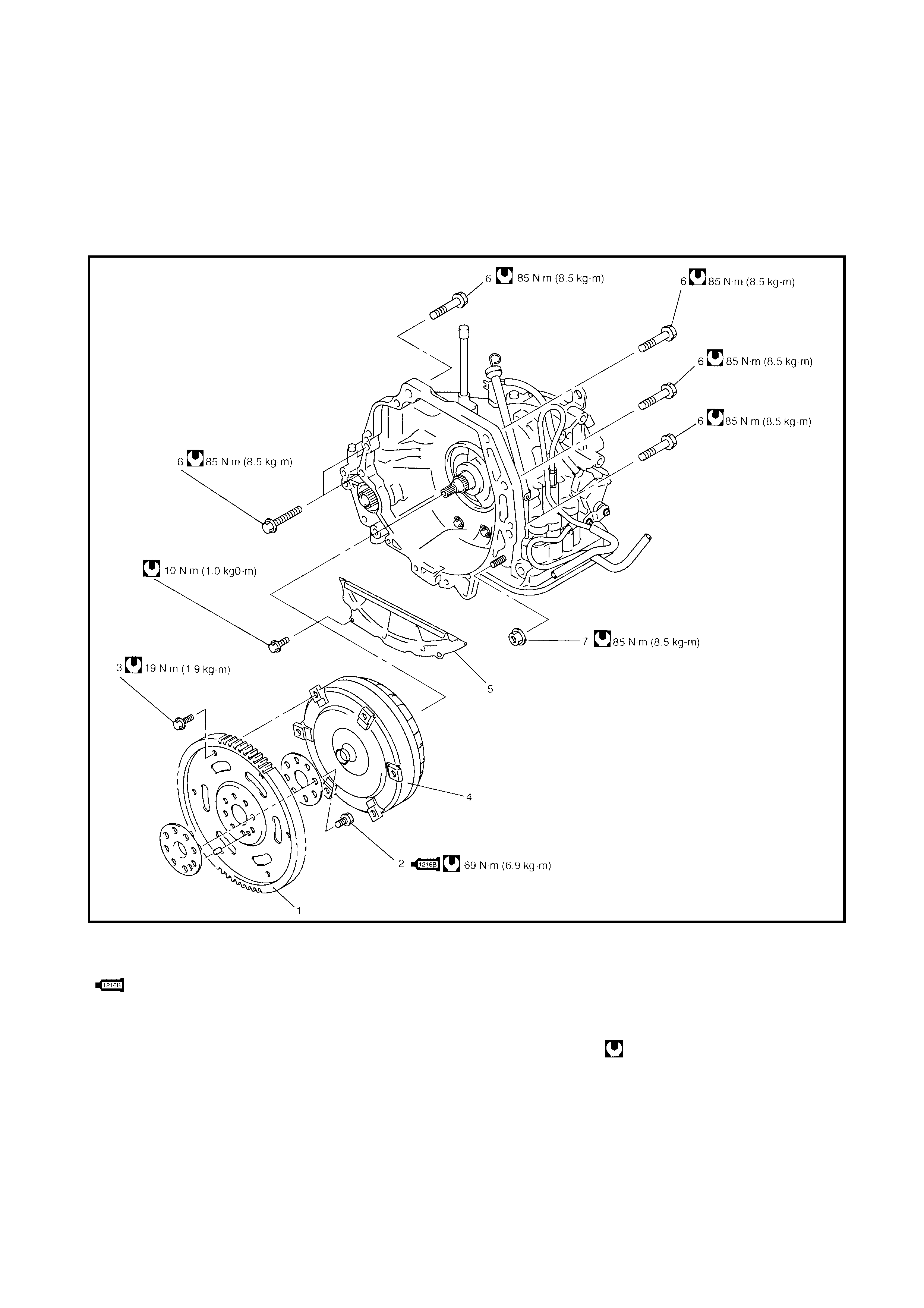
3.16 AUTOMATIC TRANSAXLE ASSEMBLY
CAUTION: When the transaxle has been replaced, learned contents, which have been stored in the
TCM memory by executing learning control, should be initialised, refer to LEARNING CONTROL
INITIALISATION in 3.12 TCM in this Section.
Neglecting this initialisation may cause excessive shift shock.
COMPONENTS
Legend
1. Drive plate 3. Drive plate to torque 6. Transaxle and engine
2. Drive plate bolt
: Apply sealant Three Bond
No. 1216B to thread.
converter bolt fastening bolt
4. Torque converter 7. Transaxle and engine
5. Transaxle housing lower fastening nut
plate Tightening torque
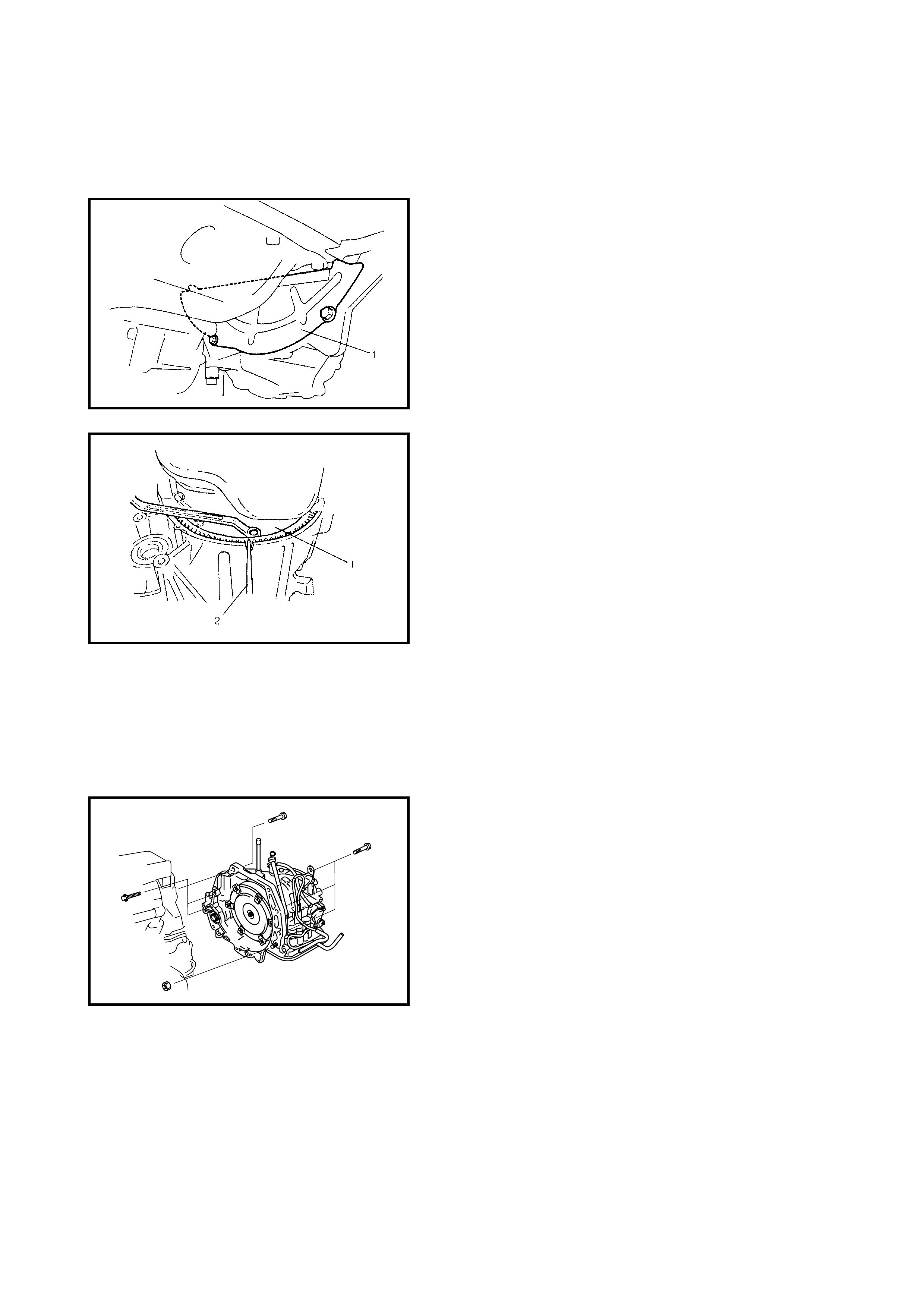
REMOVAL
1. Remove the transaxle with the engine. Refer to
Section 6A1 ENGINE MECHANICAL.
2. Remove transfer from, refer to
Section 7D TRAN SFE R .
3. Remove the transaxle housing lower plate (1).
4. Remove the drive plate to torque converter bolts.
To lock the drive plate (1), Insert flat head rod or similar
(2) into the drive plate ring gear as shown in the figure.
1. Remove the starting motor, refer to
Section 6G CRAN KIN G SY ST EM.
WARNING: Keep the transaxle (with torque converter)
horizontal or facing up during repairs. Should it be
tilted downwards, the torque converter may fall off
causing personal injury.
NOTE: When removing the transaxle from the engine,
move it parallel with the crankshaft and take care not to
apply excessive force to the drive plate and torque con-
verter.
2. Remove the bolts and nut fastening the engine and
transaxle, then remove the transaxle from the engine.
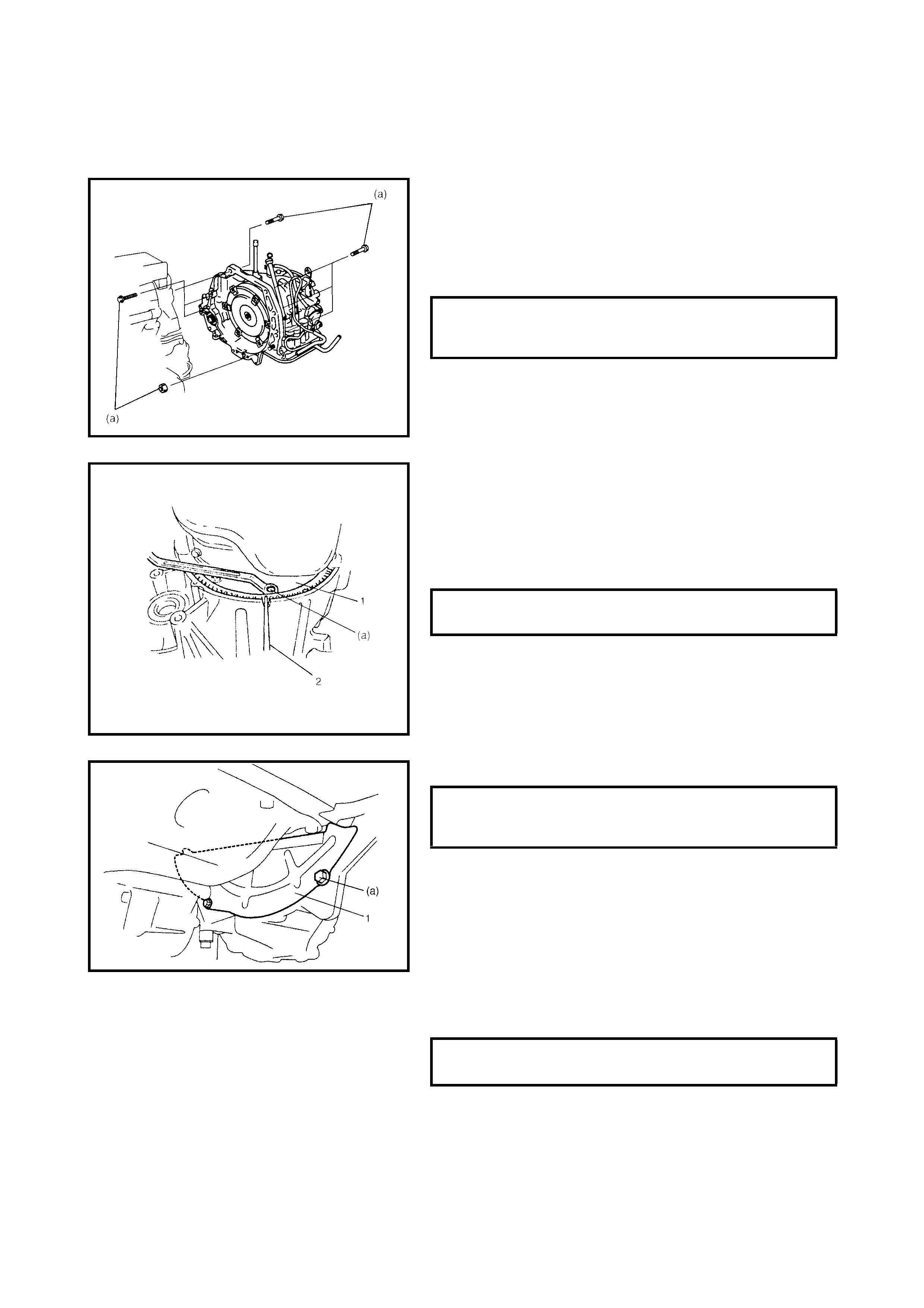
INSTALLATION
1. Make sure that the torque converter is installed
correctly to the transaxle.
Refer to 4.6 UNIT ASSEMBLY in this Section.
WARNING: Keep the transaxle (with torque converter)
horizontal or facing up during repairs. Should it be
tilted downwards, the torque converter may fall off
causing personal injury.
2. Attach the transaxle to the engine.
3. Tighten the drive plate to torque converter bolts.
Align the bolt holes of the drive plate and torque
converter then tighten bolts through torque converter
housing lower plate opening.
Lock the drive plate (1) by inserting a flat head rod or
similar (2) into the drive plate gear.
4. Install the transaxle housing lower plate (1).
5. Install the starter motor, refer to
Section 6G CRAN KIN G SY ST EM.
6. Install the transfer referring to Section 7D TRANSFER.
7. Install the engine with the transaxle assembly to the
vehicle. Refer to Section 6A1 ENGINE MECHANICAL.
TRANSAXLE & ENGINE FASTENING
BOLTS & NUT (a)
TORQUE SPECIFICATION 85 Nm
DRIVE PLATE TO TORQUE CON-
VERTER BOLTS (a) 19 Nm
TRANSAXLE HOUSING LOWER PLATE
BOLTS (a)
TORQUE SPECIFICATION 10 Nm
STARTER MOTOR BOLT & NUT
TORQUE SPECIFICATION 50 Nm

4. UNIT REPAIR
When repairing the automatic transaxle, it is necessary to conduct an on-vehicle test to help determine the
cause of any problems.
It can then be determined if an A/T overhaul is required. If the transaxle is disassembled without a preliminary
on-vehicle test, the cause of the problem may not be clear resulting in repairs that are not necessary.
4.1 PRECAUTIONS
As the automatic transaxle consists of precision components, the following cautions should be strictly
observed when handling parts in disassembly and reassembly.
• Disassembling the valve body assembly is PROHIBITED except for some minor parts. To confirm which
parts may be disassembled, refer to VALVE BODY in 4.5 DIFFERENTIAL ASSEMBLY in this Section.
• When the com ponent parts of the forward clutch and /or the O/D and 2nd coast br ake (namely the clutc h
disc, brake disc, retaining plate and/or separator plate) have been replaced, al learned contents, which
have been stored in the TCM memory by executing learning control, should be initialised, refer to
3.12 TRANSMISSION CONTROL MODULE - LEARNING CONTROL INITIALISATION in this Section.
• Clean the transaxle to prevent dirt from entering the transaxle during removal and installation.
• Select a clean place free from dust and dirt for overhauling.
• Place a rubber mat on the work bench to protect parts from damage.
• Work gloves or shop cloth should not be used for cleaning. (Use a nylon cloth or a paper towel.)
• When separating the ca se jo in t, do no t pry wit h a sc rewdri ver o r simi lar b ut tap lig htly with a plas tic h am-
mer.
• Wash the disas s emb led parts in ATF (Au t om atic Transaxle Fl uid) o r ke rosene (taking care n ot t o a ll ow A /
T fluid or kerosene to splash on your face, etc.) and confirm that all fluid passages are not clogged by
blowing compressed air through them. Use kerosene to wash the discs, resin washers and rubber parts.
• Replace all gaskets, oil seals and O-rings with a new ones.
• Apply A/T fluid to sliding or rotating parts before reassembly.
• New discs should be soaked in A/T fluid for at least 2 hours before use.

4.2 PART INSPECTION AND CORRECTION TABLE
4.3 UNIT DISASSEMBLY
CAUTION:
• Thoroughly clean the transaxle exterior before overhauling it.
• Keep the working table, tools and hands clean when overhauling the A/T assembly.
• Take care when handling aluminum parts to avoid damage.
• Do not expose removed parts to dust. Always keep them clean.
Part Inspect for Correction
Casted part, machined part Small flaw, burr Remove with oil stone.
Deep or grooved flaw Replace part.
Clogged fluid passage Clean with air or wire.
Flaw on installing surface, residual gasket Remove with oil stone or replace
part.
Crack Replace part.
Bearing Uneven rotation Replace.
Streak, pitting, flaw, crack Replace.
Bushing, thrust washer Flaw, burr, wear, burning Replace.
Oil seal, gasket Flawed or hardened seal ring Replace.
Worn seal ring on its periphery or side Replace.
Piston seal ring, oil seal, gasket, etc. Replace.
Gear Flaw, burr Replace.
Worn gear tooth Replace.
Splined part Burr, flaw, torsion Correct with oil stone or replace.
Snap ring Wear, flaw, distortion Replace.
No interference Replace.
Thread Burr Replace.
Damage Replace.
Spring Settling, sign of burning Replace.
Friction plate Wear, burning, distortion, damaged claw Replace.
Separator plate, retaining plate Wear , burning, distortion, damaged claw Replace.
Sealing surface (where lip
contacts) Flaw, rough surface, stepped wear, for-
eign material Replace.
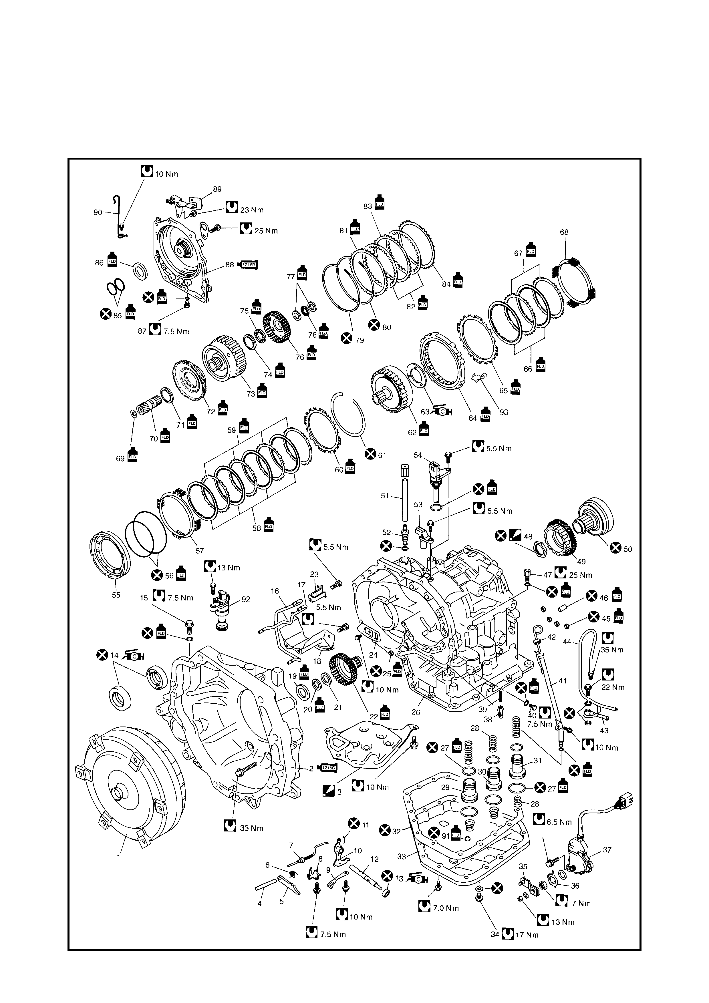
COMPONENTS
NOTE: The oil pump assembly, direct clutch assembly, forward and reverse clutch assembly , 2nd brake piston
assembly, O/D and 2nd coast brake piston and return spring, differential assembly, countershaft assembly
and valve body assembly are not shown in figure below. For details of these components, refer to
4.4 DISASSEMBLY/ASSEMBLY OF SUBASSEMBLY in this Section.
Legend
1. Torque converter 38. Cooler check valve 67. 2nd brak e separator
plate
2. Torque converte r housing
: Apply se alant Three Bond
No. 1216B to m ating
surface to transaxle case.
39. Spring
40. Transaxle case plug 68. 2nd brake return spring
subassembly
41. Fluid filler tube
42. Fluid level gauge 69. Front sun gear thrust
bearing race
3. Oil strain er assem bly
: Replace oil strainer
when overhauling.
43. Fluid cooler inlet pipe
44. Fluid cooler outlet pipe 70. Front planetary sun gear
45. 2nd brak e gas ket 71. Plan et ary gea r thrust
bearing
4. Parking lock pawl shaft 46. Brake drum gasket
5. Parking lock pawl 47. Fluid outlet union 72. One-way clutch No.1
assembly
6. Parking lock pawl return
spring 48. Reduction drive gear
nut
: After tightening nut so
as rotational torque of
reduction drive gear to
be in specified value,
caulk nut securely.
73. Rear planetary sun gear
subassembly
7. Parking lock pawl rod
8. Parking lock pawl bracket 74. Rear sun gear thrust
bearing race
9. Manual dete nt spring
10. Manual valve lever 75. Rear sun gear thrust
bearing
11. Manual valve lever pin
12. Manual shift shaft 49. Reduction drive gear 76. Forward clutch hub
13. Manual shift shaft oil seal
: Apply Lithium grease to oil
seal lip.
50. Planetary ring gear
subassembly 77. Intermediate shaft thrust
bearing race
51. Breather hose 78. Intermediate sh aft thrust
bearing
14. Differential sid e oil se al
: Apply Lithium grease to oil
seal lip.
52. Breather union
53. Input shaft speed
sensor 79. 2nd brake piston
snap ring
15. Torque converter
housing plug 54. Valve body harness 80. O/D and 2nd coast brake
retaining plate snap ring
55. 1st and reverse brake
piston
16. Lubrication LH tube 81. O/D and 2nd coast brake
reta ini ng pla te
17. Lubrica tion RH tube 56. O-ring
18. Fluid reservoir RH plate 57. 1st and reverse brake
return spring
subassembly
82. O/D and 2nd coast brake
disc
19. Input shaft front thrust
bearing 83. O/D and 2nd coast brake
separator pl ate
20. Input shaft rear thrust
bearing 58. 1st and reverse brake
disc 84. O/D and 2nd coast brake
rear plate
21. Input shaft rear thrust
bearing race 59. 1st and reverse brake
sepa rator plate 85. Rear cover seal ring
22. Direct clutch hub 60. 1st and reverse brake
retaining plate 86. Reverse clutch drum
thrust bearing
23. Lubrication tube clamp
24. Fluid reservoir LH plate 61. 1st and reve rse brake
snap ring 87. Rear cover plug
25. Governor apply
No.2 gasket 88. Transaxle rear cover
Apply sealant Th ree Bond
No. 1216B to
mating surface.
62. Planetary gear
assembly
26. Automatic transaxle case
27. Accumulator piston
O-ring 63. Planetary carrier thrust
washer
: Apply Lithium grease to
slide con tact face.
89. Harness bracket
90. Select cable clam p
28. Accumulator spring 91. Governor apply No.1
gasket
29. C2 accumulator piston
30. C1 accumulator piston 92. O utput shaft speed
sensor (VSS)
31. B1 accumulator piston 64. One-way clutch No.2
assembly
32. Oil pan gasket 93. O ne-way clutch outer
race retainer
33. Oil pan 65. 2nd brake ret a ining
plate
34. A/T fluid drain plug Do not reuse.
35. Manual select leve r
36. Lock washer 66. 2nd brake disc
plate Apply automatic
transa xle fluid.
37. Transm is si on rang e
sensor
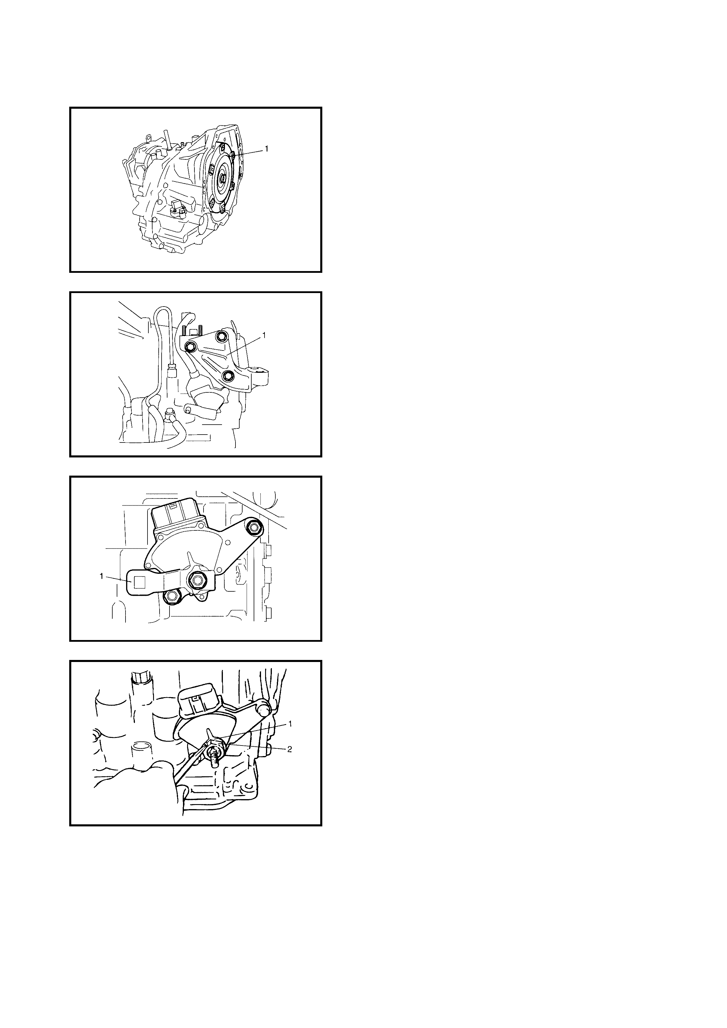
DISASSEMBLY
CAUTION: When removing the torque converter keep it
as straight (level) as possible to avoid damaging the oil
seal lip.
1. Remove the torque converter (1).
2. Remove the engine mount LH bracket (1).
3. Remove the manual select lever (1).
4. Unstake the lock wa sher (1) , then r emove t he lock nut
(2) and the lock washer (1).
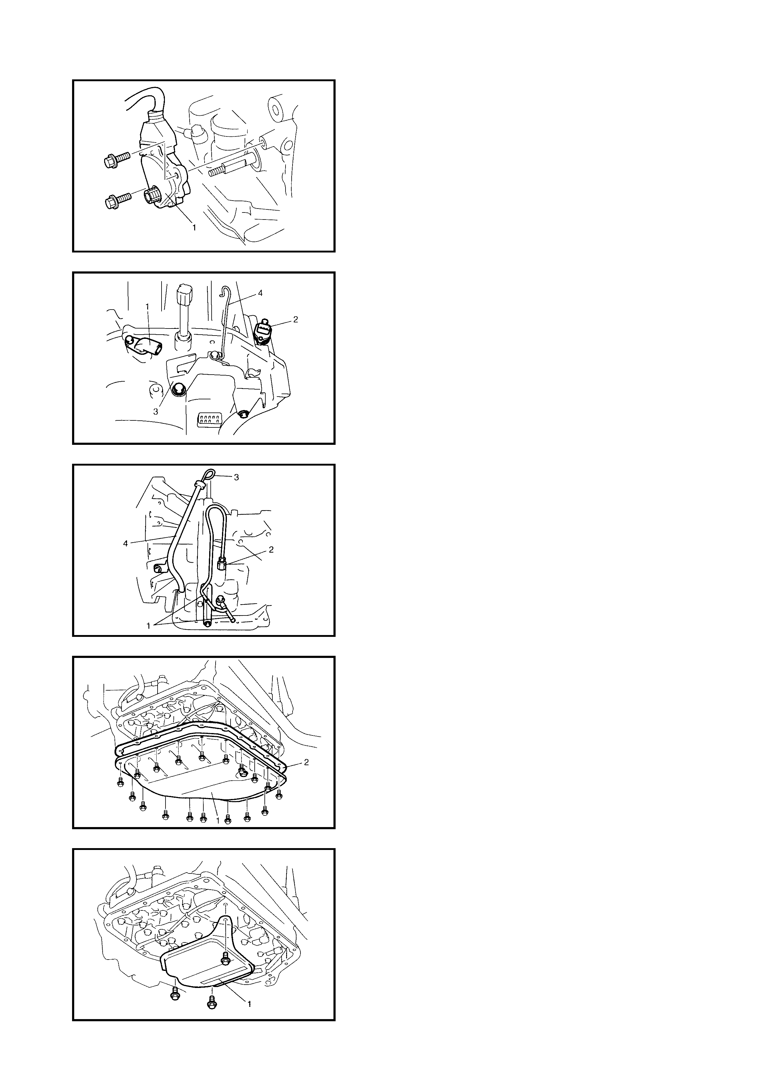
5. Remove the transmission range sensor (1).
6. Remove the input shaft speed sensor (1) and the
output shaft speed sensor (VSS) (2).
7. Remove the harness bracket (3) and the select cable
clamp (4).
8. Remove the fluid cooler pipes (1) and the fluid outlet
union (2).
9. Remove the fluid level gauge (3) and the fluid filler tube
(4).
NOTE:
• When removing the oil pan, do not turn the transaxle
over as this will contaminate the valve body with for-
eign matter from the bottom of the oil pan.
• Wh en removing the oil pan, tap around i t lightly wi th a
plastic ha mme r. Do not p ry it o ff usin g a s crewd r iver or
similar.
10. Remove the oil pan (1) and the oil pan gasket (2).
11. Remove the oil strainer assembly (1).
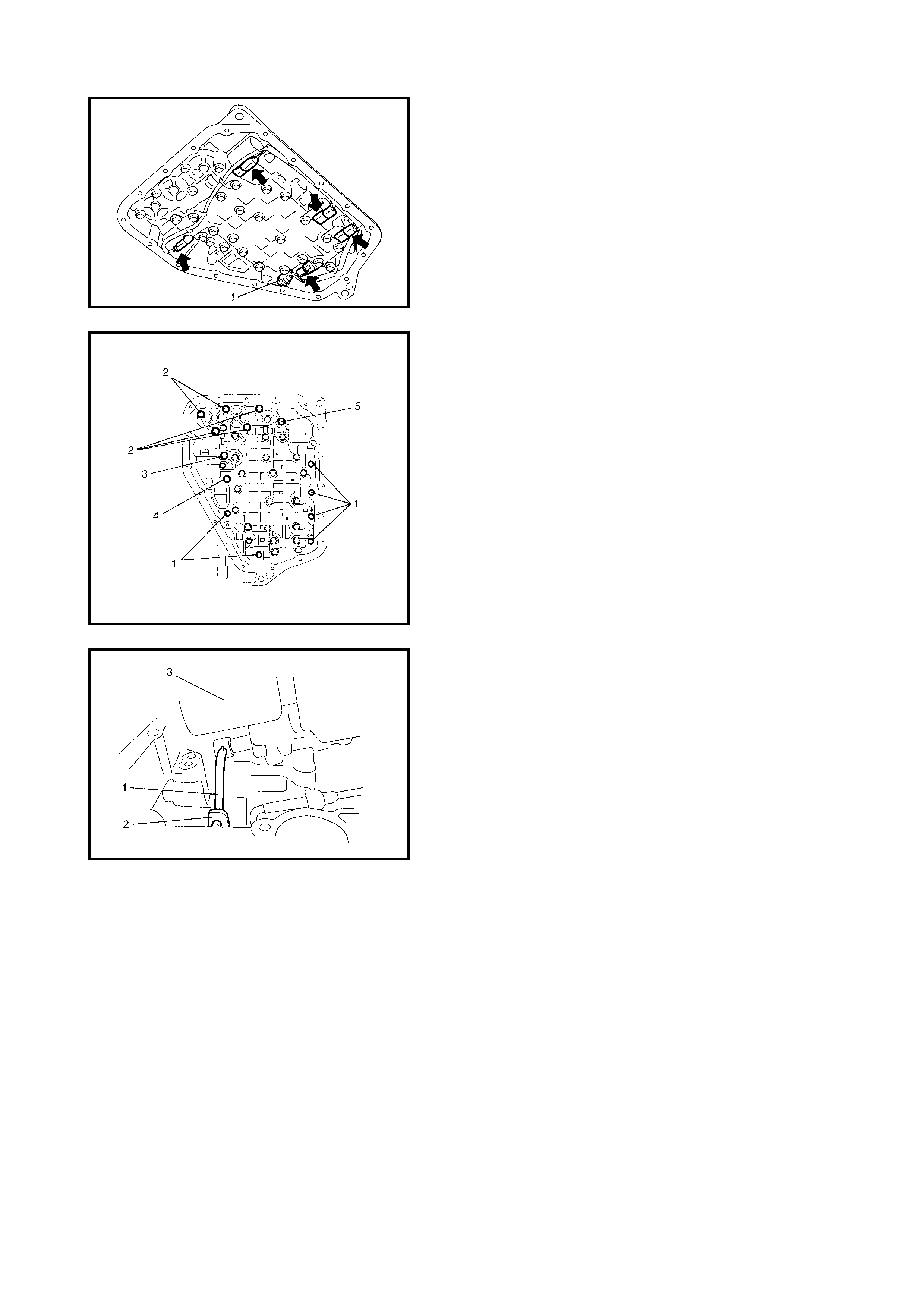
12. Disconnect the connectors from the solenoid valves,
and transmission fluid temperature sensor (1).
CAUTION: Do not let the manual valve fall off when
removing the valve body assembly.
NOTE: There are fi ve kinds of bo lts (bolts A(1), B(2) , C(3),
D(4), and E(5)) fixing the valve body assembly.
13. Remove the valve body assembly bolts.
14. Remove the manual valve rod (1) from the manual
valve lever (2), then remove the valve body assembly
(3).
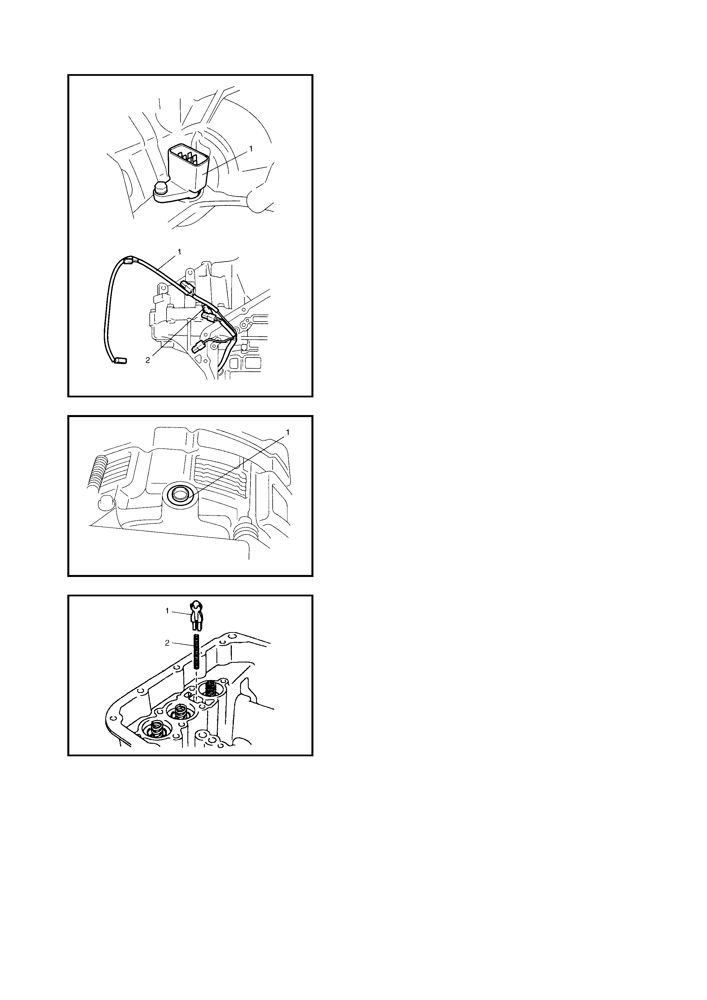
CAUTION: When removing the valve body harness (1)
from the transaxle case, take care not to damage the
transmission fluid tempe rature sensor (2 ) at the narr ow
exit of the case.
Careless s ensor tr eatment may cause se nsor malfun c-
tion.
15. Remove the valve body harness (1).
16. Remove the governor apply No.1 gasket (1).
17. Remove the cooler check valve (1) and spring (2).
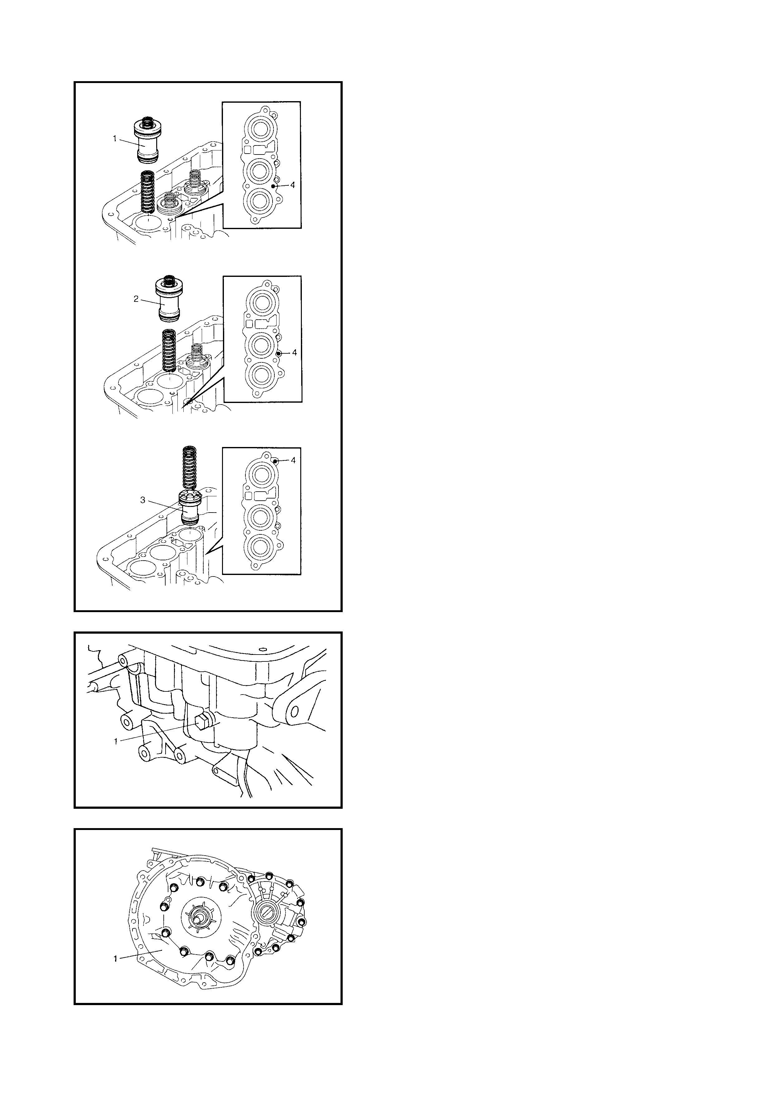
NOTE: Do not push the accumulator pistons in before
removing them or compressed fluid in the accumulator may
spew out of the hole.
18. Remove the accumul ato r pis ton s and sp rings .
To remove C2 (1), C1 (2) and B1 (3) accumulator
pistons and springs, cover with rag then force low-
pressu re comp ressed ai r into hole (4 ) as shown in the
figure and pop each piston into rag.
19. Remove the transaxle case plug (1).
20. Remove the torque converter housing bolts.
21. Remove the torque converter housing (1) by tapping
around it lightly with a plastic hammer.
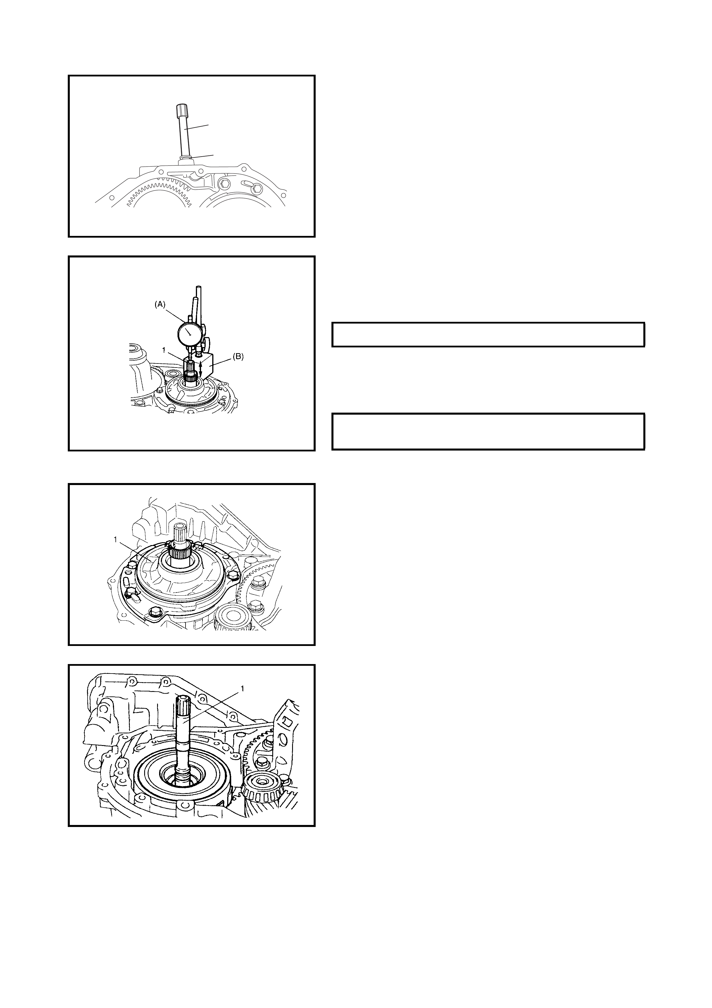
22. Remove the breather hose (1).
23. Remove the breather union (2).
24. Measure the input shaft thrust play.
Apply a dial gaug e, specia l tools 09900-2 0607 (A) and
09900-20701 (B), onto the input shaft end (1) and
measure the thrust play of the input shaft.
When the input shaft thrust play is out of specification,
select an input shaft front thrust bearing with the correct
thickness from the list below and replace.
25. Remove the oil pump assembly (1).
26. Remove the direct clutch assembly (1).
1
2
INPUT SHAFT THRUST PLAY 0.3 - 0.9 mm
AVAIL.ABLE INPUT SHAFT FRONT
THRUST BEARING THICNESS 0.8 mm
1.4 mm
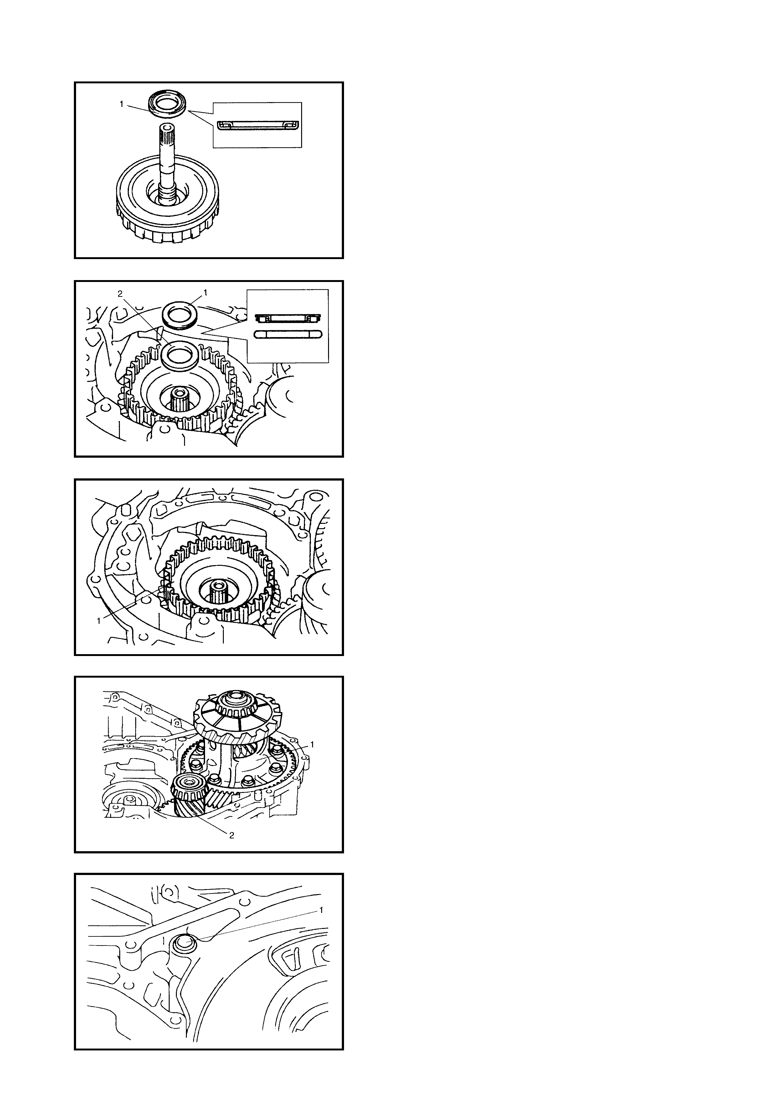
27. Remove the input shaft front thrust bearing (1).
NOTE: If the inp ut sha ft front thrus t bearing is no t in pl ace,
it may have been removed with the oil pump assembly
.
28. Remove the i nput shaft rear thrust bea ring (1) and the
thrust bearing race (2).
NOTE: If the input shaft rear thrust bearing is not in place, it
may have been removed with the direct clutch assembly.
29. Remove the direct clutch hub (1).
30. Remove the differential assembly (1) and the counter
shaft assembly (2).
31. Remove the governor apply No.2 gasket (1).
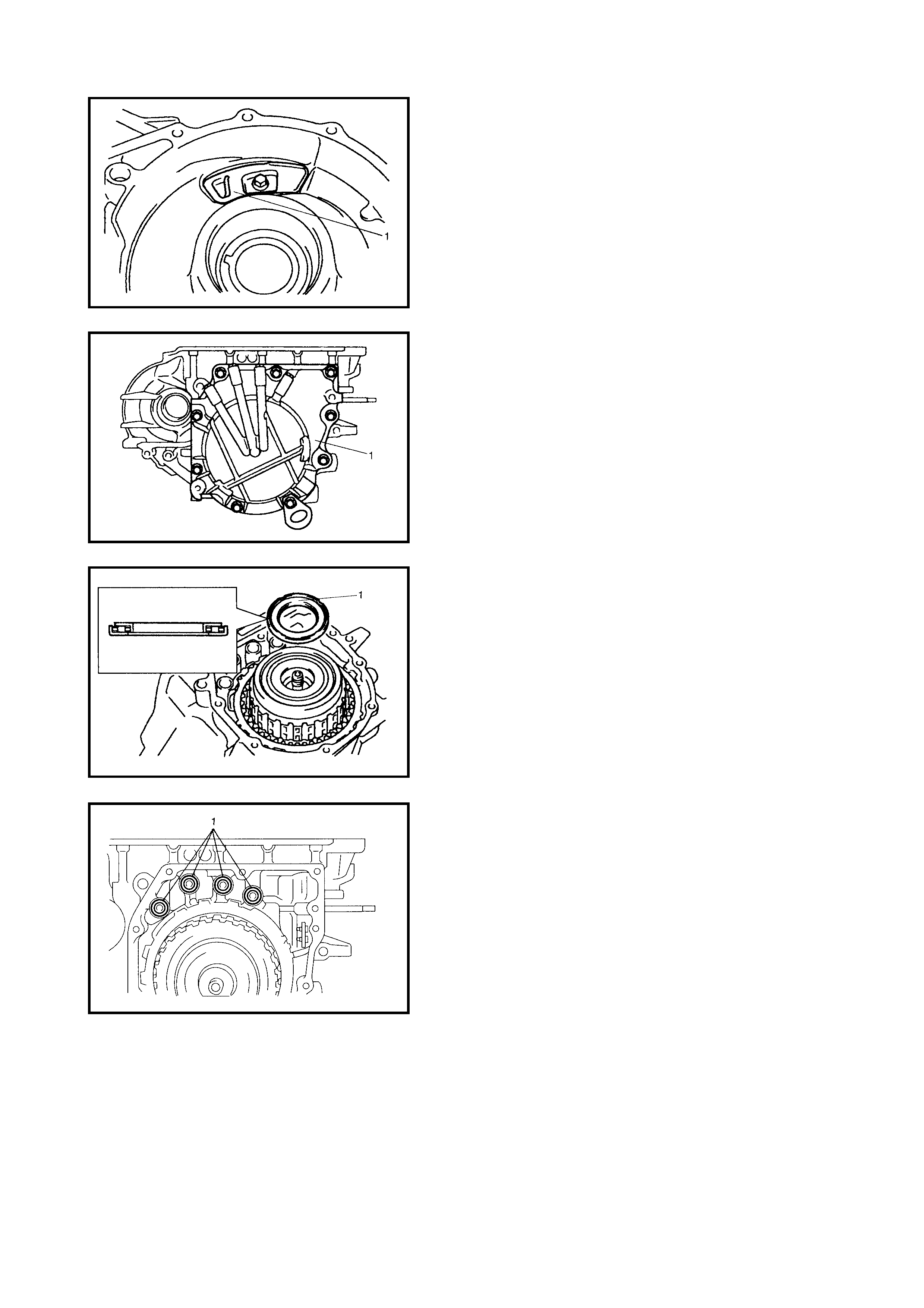
32. Remove the fluid reservoir LH plate (1).
33. Turn the transaxle over and remove the rear cover
assembly (1).
34. Remove the reverse clutch drum thrust bearing (1).
NOTE: If the reverse clutch drum thrust bearing is not in
place, it may have been removed with the rear cover
assembly.
35. Remove the 2nd brake gasket (1).
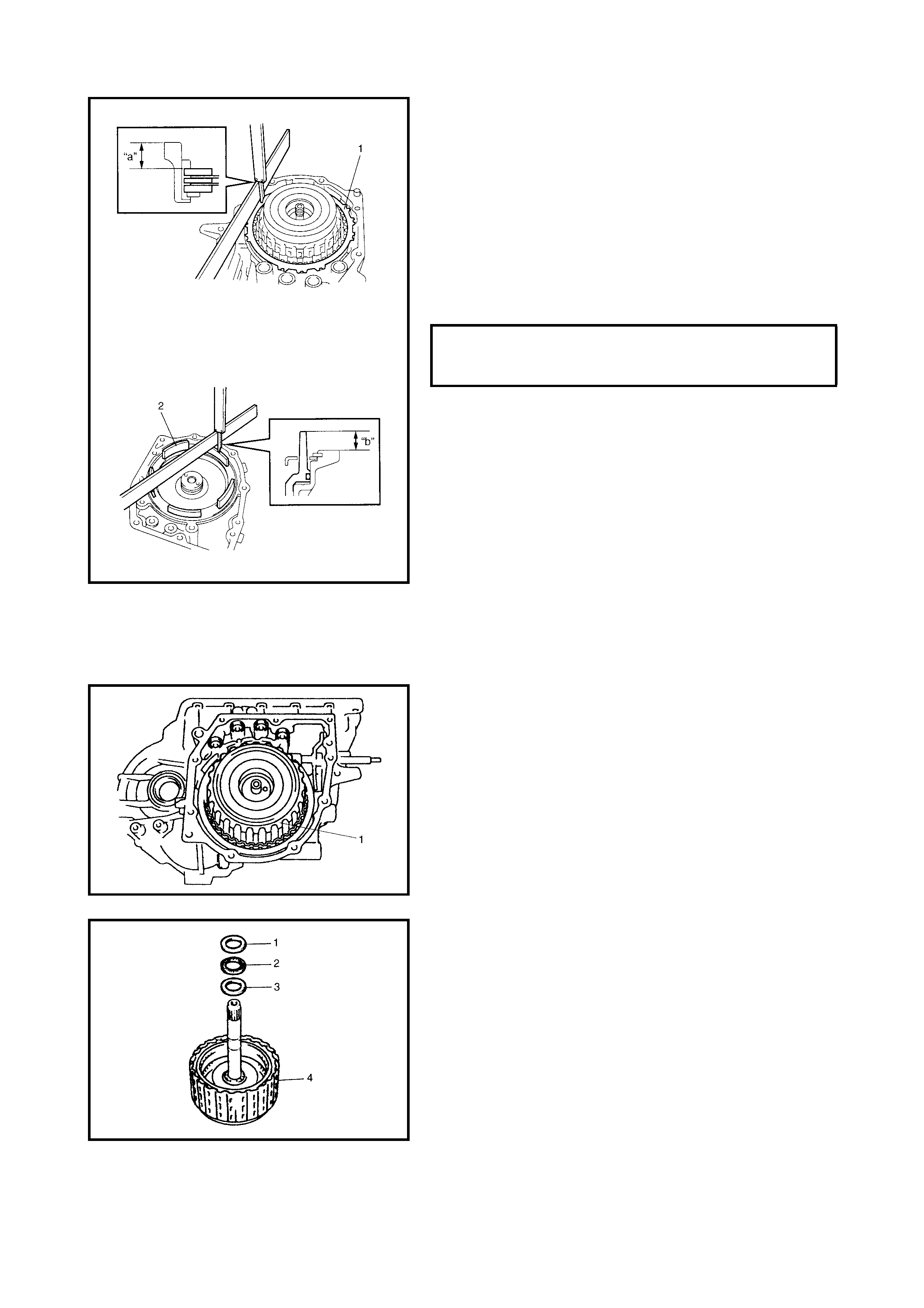
36. Measure the O/D and 2nd coast brake piston stroke.
• Measure dim ension “a” from mating the surface of the
transaxle case to the O/D and 2nd coast brake rear
plate (1) using a straightedge and a micrometer cali-
per.
• Measure dimension “b” from the O/D and 2nd coast
brake piston (2) to the rear cover assembly mating sur-
face using a straightedge and a micrometer caliper.
• Cal cul ate the piston str oke fr om the mea su red val ue of
dimensions “a” and “b”.
• Piston stroke = “a” – “b”
If the piston stroke exceeds the specification above,
inspect and replace plates and discs.
CAUTION: When the component parts of the O/D and
2nd coast brake (namely brake disc, retaining plate,
separator plate and/or rear plate) have been replaced,
learned contents, which have been stored in the TCM
memory by executing l ear ning c ontrol , should be initi-
alised, refer to LEARNING CONTROL INITIALISATION
in 3.12 TRANSMISSION CONTROL MODULE in this
Section.
Neglectin g this init ialis atio n may ca u se ex ces sive shift
shock.
37. Remove the forward and reverse clutch assembly (1).
38. Remove the intermediate shaft thrust bearing front
race (1), thrust bearing (2) and rear race (3) from the
forward and reverse clutch assembly (4).
NOTE: If the intermedia te sh aft thrust beari ng and /or ra ces
are not in place on the forward and reverse clutch assem-
bly, they may have remained in the transaxle.
O/D & 2ND COAST BRAKE PISTON
STROKE STANDARD 0.65 - 1.05 mm
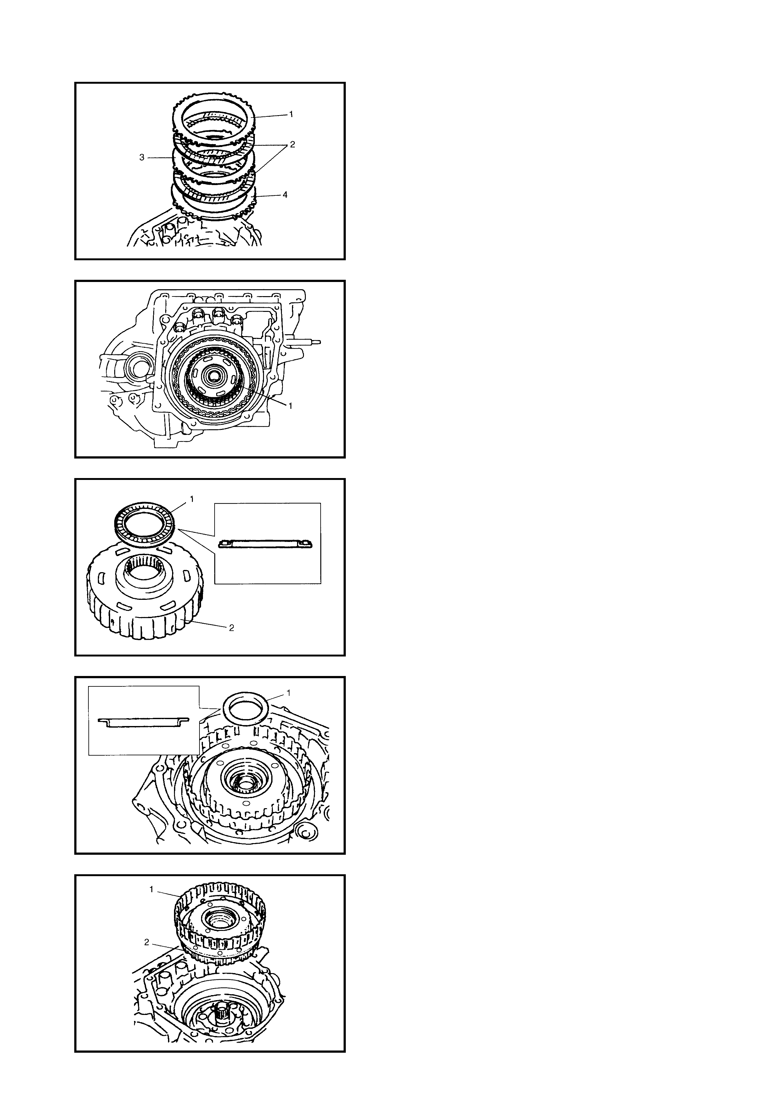
39. Remove the O/D and 2nd coast brake rear plate (1),
discs (2), separator plate (3) and retaining plate (4).
40. Remove the forward clutch hub (1).
41. Remove the rear sun gear thrust bearing (1) from the
forward clutch hub (2).
NOTE: If the rear sun ge ar thr ust beari ng is not in place on
the forward clutch hub, it may have remained in the tran-
saxle
.
42. Remove the rear sun gear thrust bearing race (1).
43. Remove the rear planetary sun gear subassembly (1)
and the one-way clutch No.1 assembly (2).
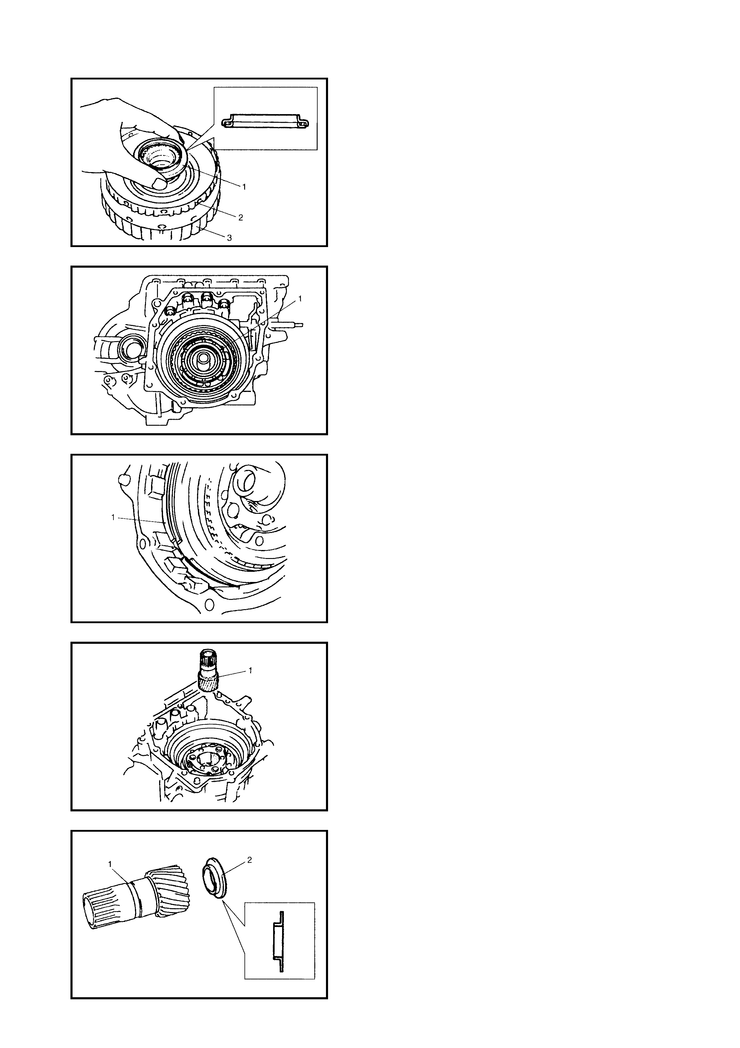
44. Remove the planetary gear thrust bearing (1).
NOTE: If the planetary gear thrust bearing is not in place
on the one-way clutch No.1 assembly, it may have
remained in the transaxle.
45. Remove the one-way clutch No.1 assembly (2) from
the rear planetary sun gear subassembly (3).
46. Remove the planetary carrier thrust washer (1).
47. Remove the O/D and 2nd coast brake retaining plate
snap ring (1).
48. Remove the front planetary sun gear (1).
49. Remove the front sun gear thrust bearing race (2) from
the front planetary sun gear (1).
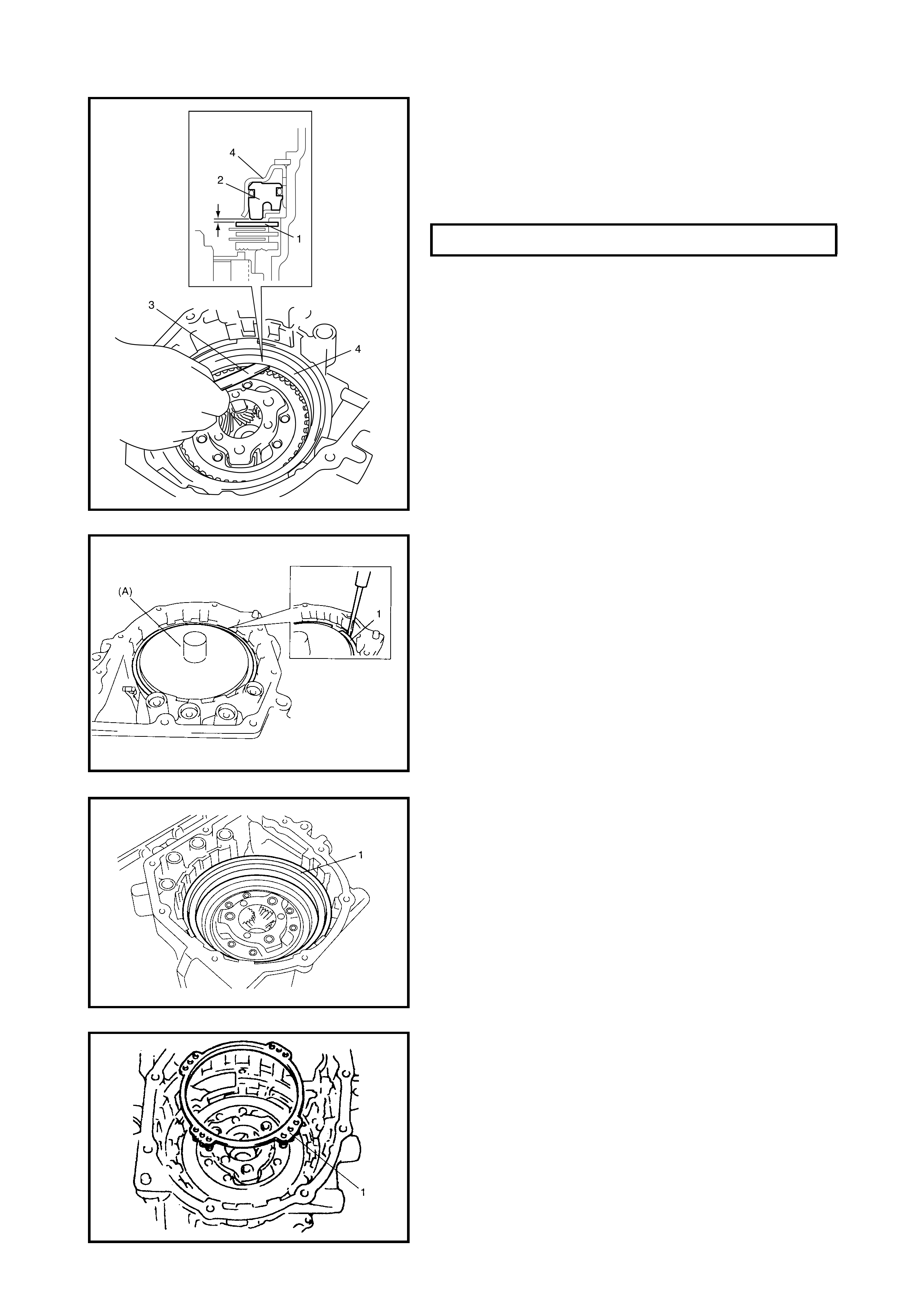
50. Before disassembling the 2nd brake piston assembly
(4), check the 2nd brake piston stroke by measuring
the clearance between the 2nd brake separator plate
(1) and the piston (2) with a feeler gauge (3).
If the clearance (piston stroke) is out of specification,
replace the brake discs and plates with new ones.
CAUTION: When the component parts of the 2nd brake
(namely the brake disc, retaining plate and/or separa-
tor plate) have been replaced, all learned contents,
which have been stored in the TCM memory by execut-
ing learning control, should be initialised, refer to
3.12 TRANSMISSION CONTROL MODULE - LEARNING
CONTROL INITIALISATION in this Section.
Neglectin g this init ialis atio n may ca u se ex ces sive shift
shock.
CAUTION: Do not press 2nd brake piston assembly in
more than 0.4 mm.
Excessiv e compressi on may cause d amage to th e pis-
ton assembly, return spring, plates and/or discs.
51. Using special tool 09926-96050 (A) and hydraulic
press, remove the 2nd brake piston snap ring (1).
52. Remove the 2nd brake piston assembly (1).
53. Remove the 2nd brake return spring subassembly (1).
2ND BRAKE PISTON STROKE (a) 0.40 - 1.25 mm
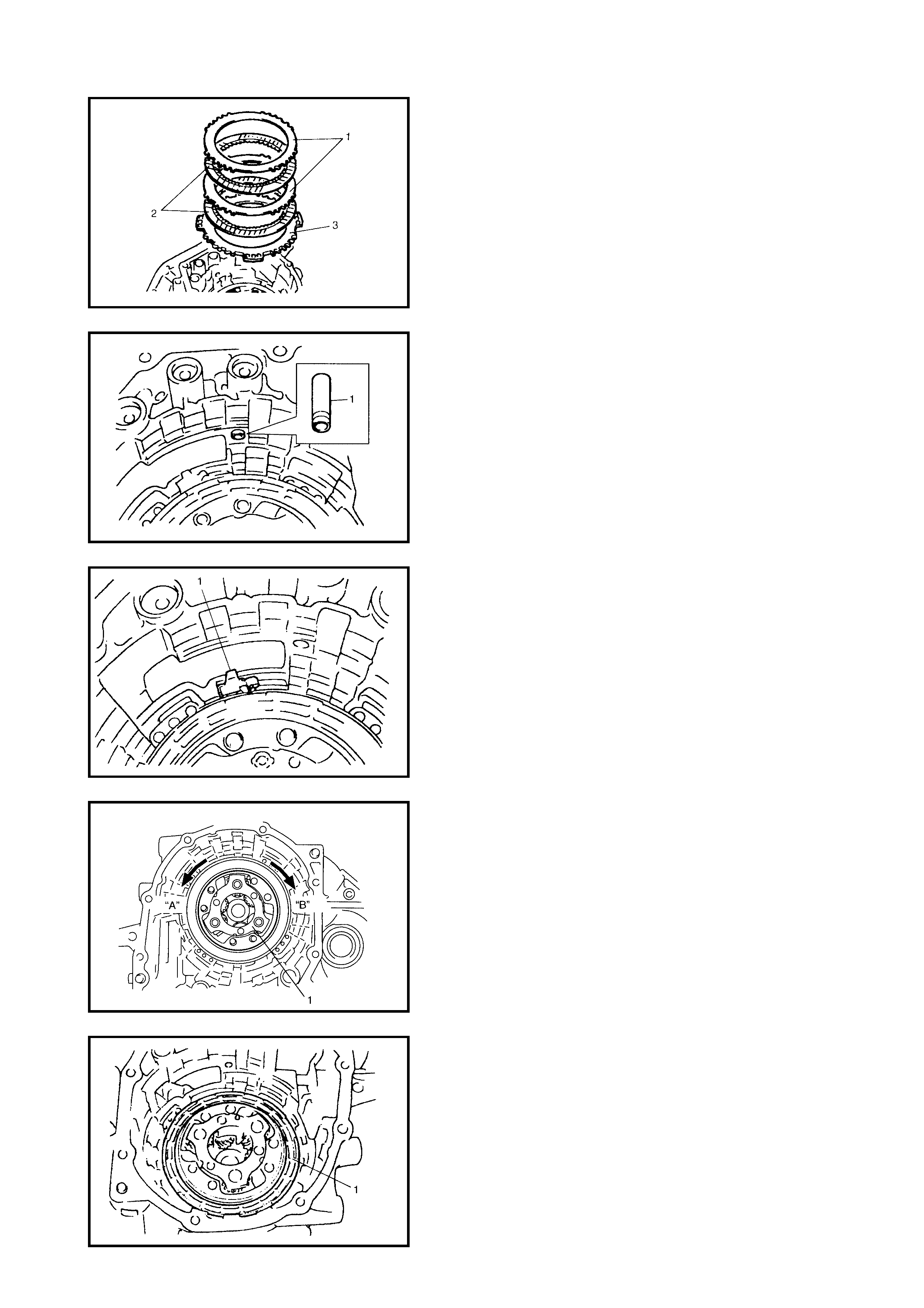
54. Remove the 2nd brake separator plates (1) discs (2)
and retaining plate (3).
55. Remove the brake drum gasket (1).
56. Remove the one-way clutch outer race retainer (1).
57. Check the one-way clutch No.2 as follows.
• Ens ure the pla netary carrier (1) rotates only in a coun-
terclockwise direction “A”, never in a clockwise
direction “B”.
• If the planetary carrier rotates both ways or does not
rotate either way, the one-way clutch No.2 assembly
will need to be replaced.
58. Remove the one-way clutch No.2 assembly (1).
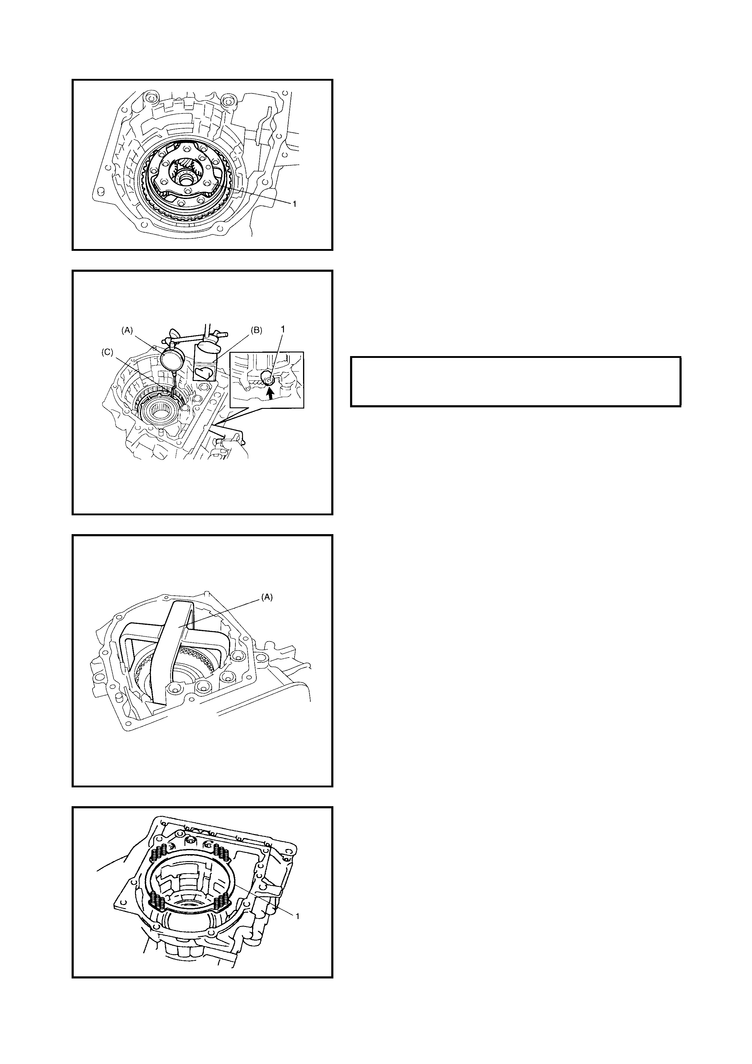
59. Remove the planetary gear assembly (1).
60. Measure the 1st and reverse brake piston stroke
• Using special tools 09900-2607 (A), 09900-20701 (B)
and 09952-06020 (C), measure the 1st and reserve
brake piston stroke when compressed air (400 – 800
kPa) is blown through the oil hole (1).
If the piston stroke exceeds the specified value, disassem-
ble, inspect and replace discs and plates.
CAUTION: Do not press the 1st and reverse brake
return spring subassembly in more than 0.8 mm.
Excessive compression may cause damage to return
spring subassembly, discs, plates and/or piston.
61. Remove the s nap ring whil e the 1st and rev erse brake
piston return springs are compressed using special
tool 09926-97620 (A) and hydraulic press.
62. Remove the 1st and reverse brake retaining plate,
discs and separator plates.
63. Remove the 1st and reverse brake return spring sub-
assembly (1).
1ST & REVERSE BRAKE PISTON
STROKE STANDARD 0.79 - 1.49 mm
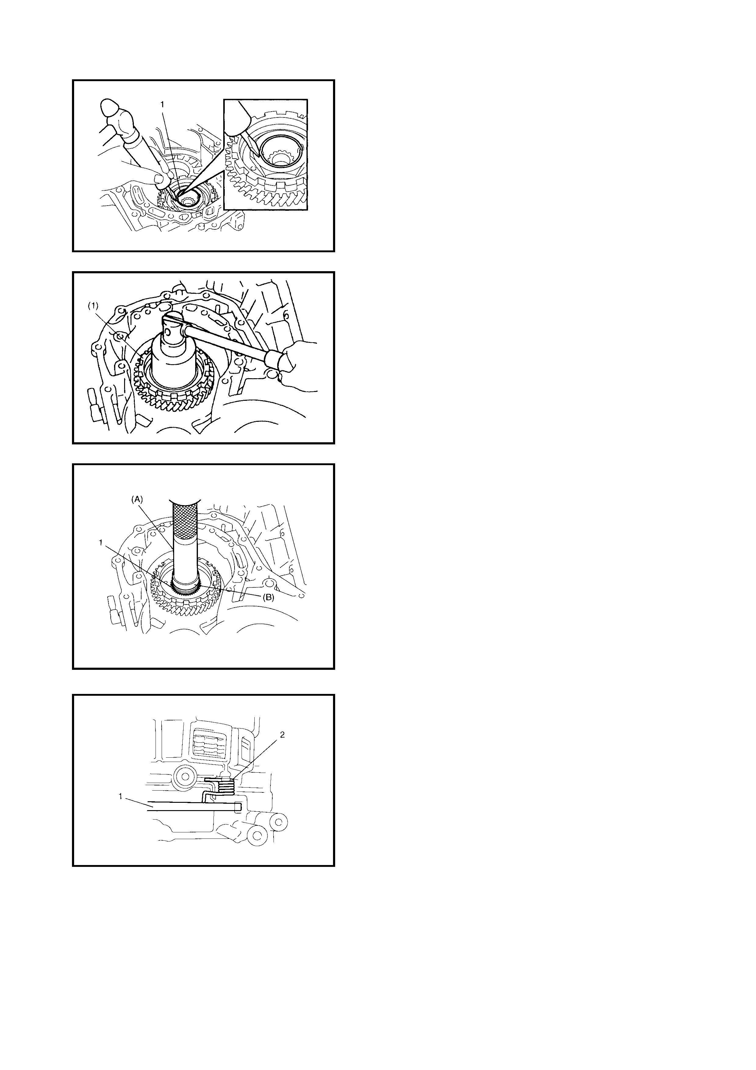
64. T urn the transaxle over and unstake the reduction drive
gear nut (1).
CAUTION:
• It is recommended that this operation should be
carried out on rubber mat to prevent damaging the
transaxle case.
• Never reuse a removed nut.
65. Secure the reduction drive gear (1) with the parking
lock pawl, then remove the reduction drive gear nut.
66. Using sp eci al too ls 09 913-8 4510 ( A), 09 923 -7821 0 ( B)
and hydraulic press, remove the planetary ring gear
subassembly (1).
CAUTION: Do not reuse the pla netary ring gear su bas-
sembly. To do so may cause damage to the planetary
gear unit and/or the reduction gears.
67. Remove the parking lock pawl shaft, the spring (2) and
parking lock pawl (1).
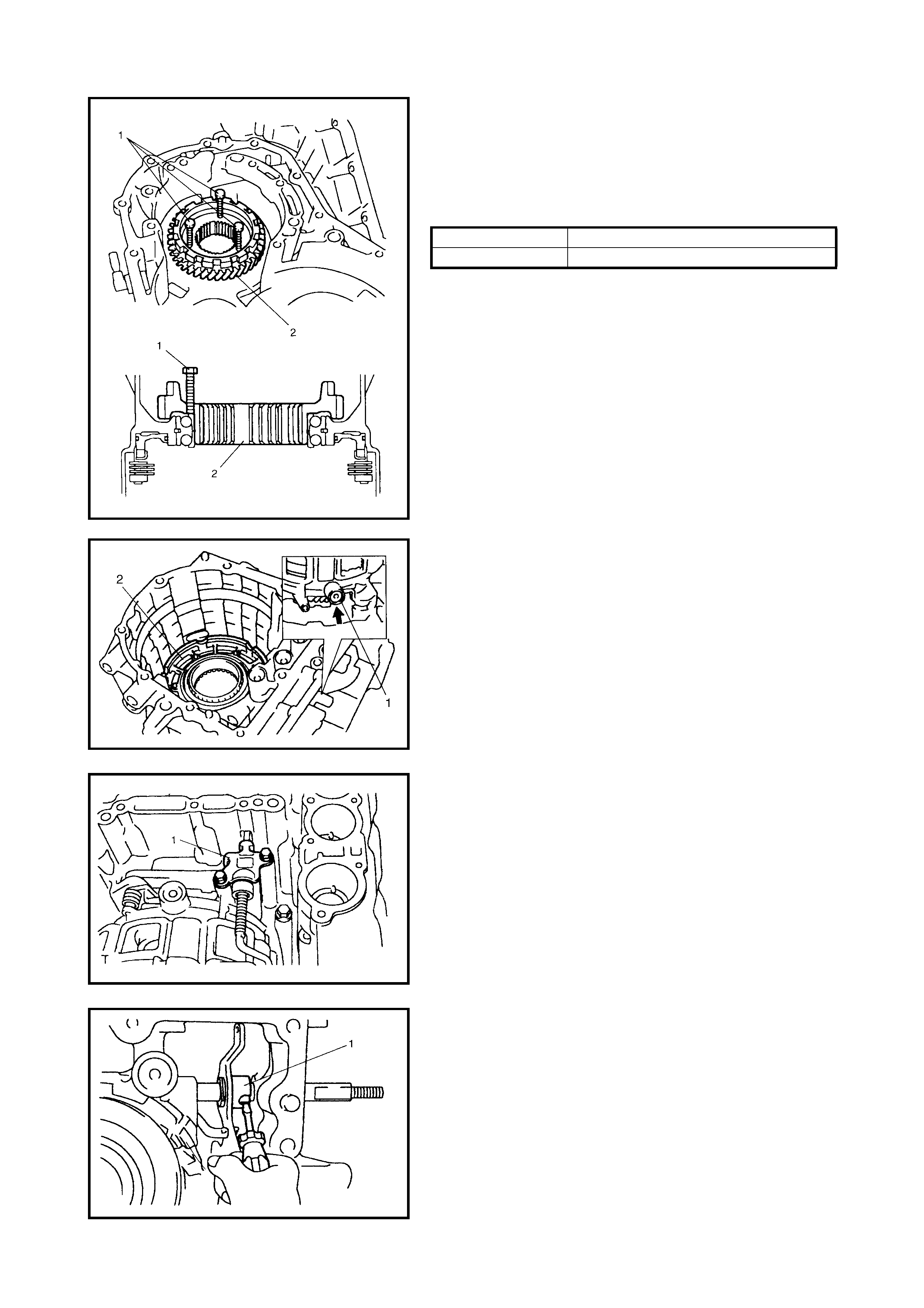
CAUTION: Screw 3 bolts into the reduction drive gear
evenly, or the reduction drive gear, bearing and tran-
saxle case may be damaged.
68. Screw 3 bolts (1 ) into th e redu cti on driv e gea r (2) the n,
remove the reduction drive gear (2).
69. Blowing compressed air from the oil hole (1) of the oil
pump, remove the 1st and reverse brake piston (2).
70. Remove the parking lock pawl bracket (1).
71. With a slotted screw driver, cut and unfold the manual
valve lever spacer (1) and proceed to remove the
manual valve lever spacer.
BOLT LENGTH
1 30 mm
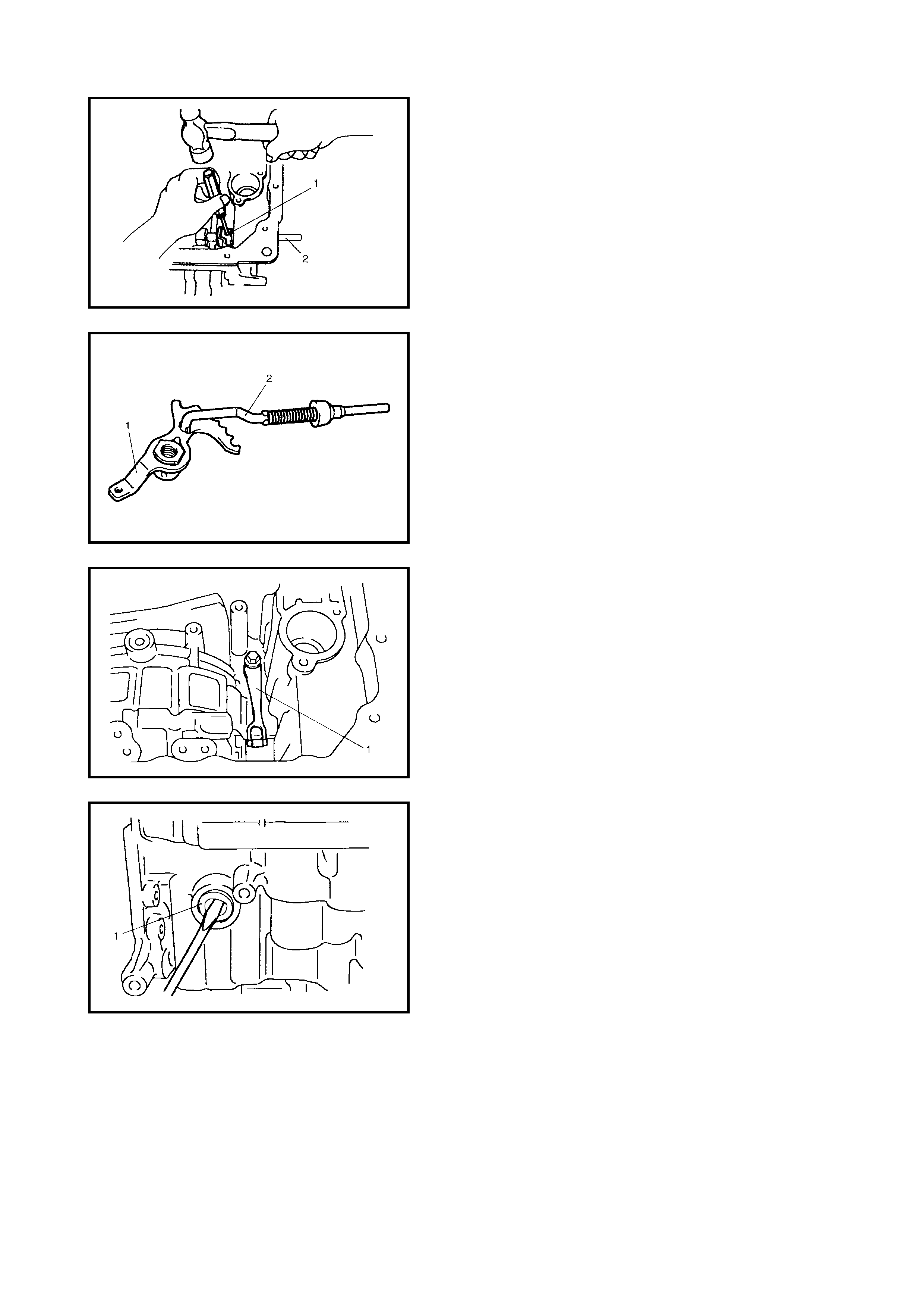
72. Using a spring pin remover (3 mm diameter) and a
hammer, drive out the manual valve lever pin (1).
73. Remove the manual shift shaft (2).
74. Remove the parking lo ck pawl rod (2) f rom the ma nual
valve lever (1).
75. Remove the manual detent spring (1).
76. Remove the manual shift shaft oil seal (1).
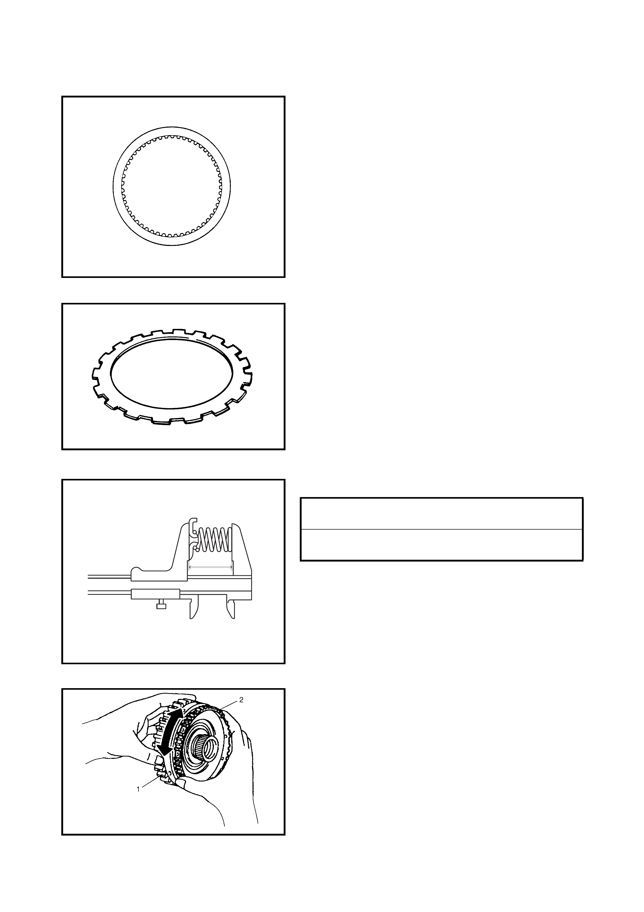
INSPECTION
Brake Discs
Dry and inspect the brake discs for pitting, burn flaking, sig-
nificant wear , glazing, cracking, charring and chips or metal
particles imbedded in lining.
If the disc s sh ow any of the ab ove co nditions , replac ement
is required.
NOTE:
• If the disc lining is flaking or discoloured, replace all
discs.
• Before assembling new discs, soak them in A/T fluid
for at least two hours.
Brake Separator Plates And Retaining Plates
Dry the plates and check for discolouration. If the plate
surface is smooth and even colour smear is indicated,
the plate can be reused. If severe heat spot discoloura-
tion or surface scuffing is present, the plate must be
replaced.
Brake return spring subassembly
Meas u re th e bra k e re turn spri ng s .
NOTE:
• Do not apply excessive force when measuring spring
free length
• Perform measurement at several points.
Evidence of extreme heat or burning in the area of the
clutch may have caused the springs to take heat set and
would require their replacement.
One-way Clutch No.1 Assembly
1. Install the one-way clutch No.1 assembly (2) to the rear
planetary sun gear subassembly (1).
2. Securing the rear planetary sun gear subassembly,
ensure that the one-way clutch No.1 assembly rotates
in one directi on only.
If the one-way clutch rotates in both directions or it
does not ro tate in ei ther di rec tio n, r eplac e it wi th a new
one.
FREE LENGTH OF 1st & REVERSE
BRAKE RETURN SPRINGS (a) 21.71 mm
FREE LENGTH OF 2ND BRAKE
RETURN SPRINGS (a) 15.85 mm
“a”
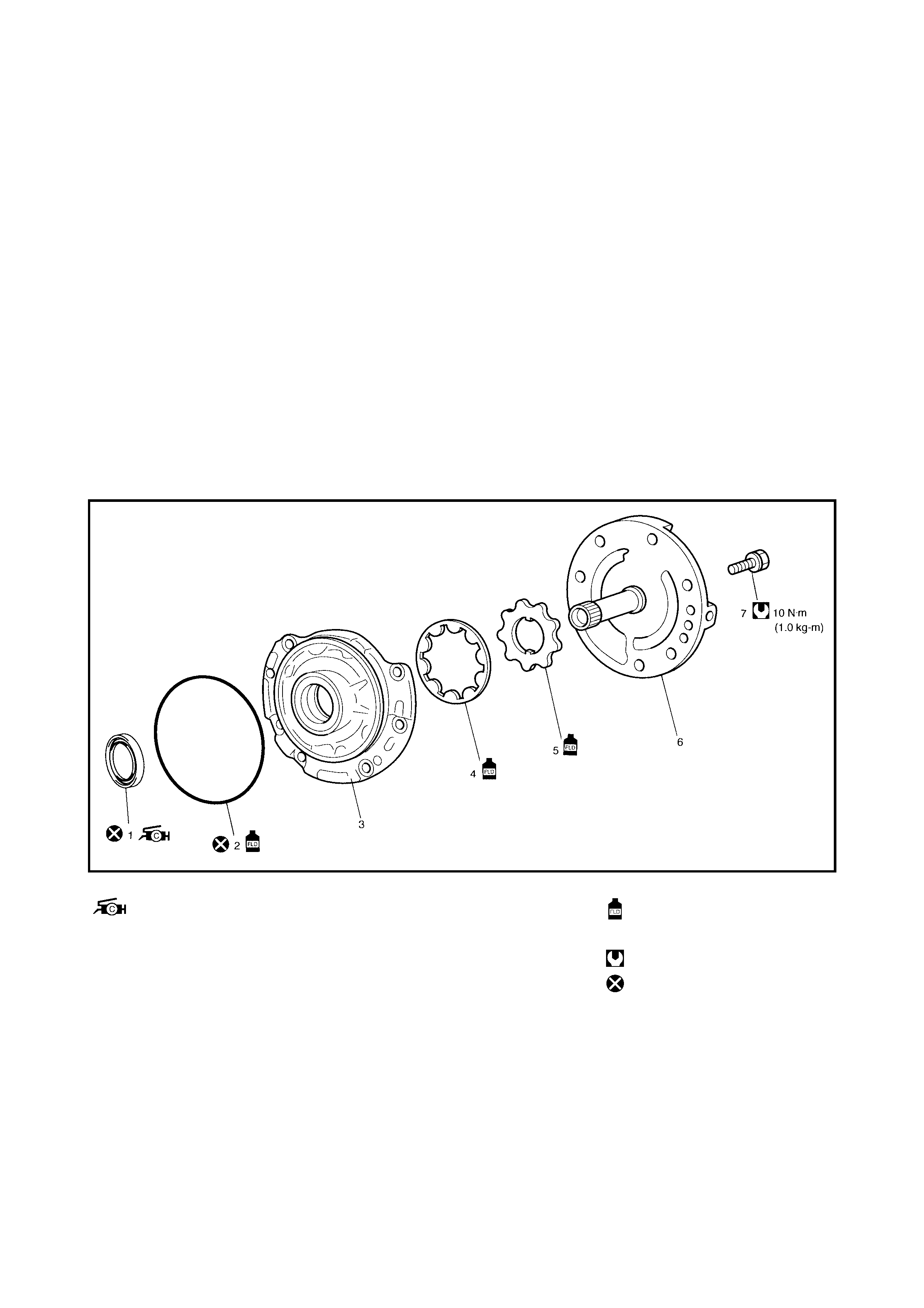
4.4 DISASSEMBLY/ASSEMBLY OF SUBASSEMBLY
CAUTION:
• Keep component parts in groups of each subassembly and avoid intermingling them.
• Clean all parts with cleaning solvent thoroughly and air dry them.
• Use kerosene or automatic transaxle fluid as a cleaning solvent.
• Do not use wiping cloths or rags to clean or dry parts.
• All oil passages should be blown out and checked to make sure that they are not obstructed.
• Protect face and eyes from solvent spray while air blowing parts.
• Check the mating surface for irregularities. Remove any irregularities and repeat cleaning.
• Soak new clutch discs and brake discs in A/T fluid for at least 2 hours before assembly.
• Replace all gaskets and O-rings with new ones.
• Apply A/T fluid to all O-rings.
• When installing the seal ring, ensure it has not expanded excessively, been extruded or pinched.
• Replace the oil seals that are removed with new ones and apply grease to their lips.
• Before installing, apply A/T fluid to sliding, rolling and thrusting surface of all component parts.
After installation, check each part for correct operation.
• Always use torque wrench when tightening bolts.
OIL PUMP
Legend 1. Oil seal
: Apply Lithium grease to oil
seal li p.
4. Oil pump driven gear Apply automatic transaxle
fluid
5. Oil pump drive gear
6. Stator shaft assembly Tightening torque
2. O-ring 7. Oil pump subassembly
bolts Do not reuse.
3. Oil pump body
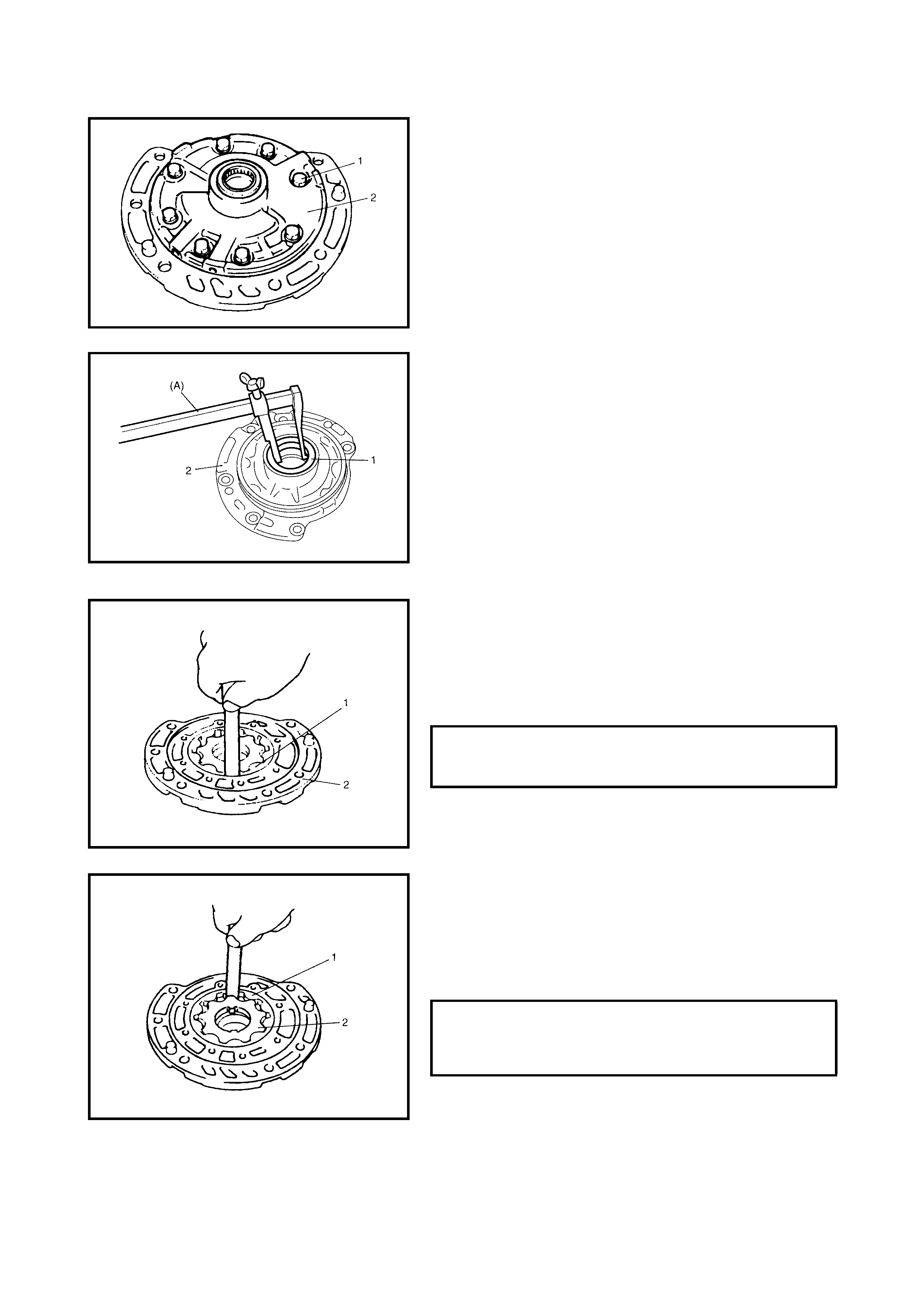
DISASSEMBLY
1. Remove the O-ring from the pump body.
2. Remove th e 8 o il pump s ubassembly bolts (1 ) and the
stator shaft assembly (2).
3. Remove th e oil seal (1) from th e pump body (2) using
special tool 09913-50121 (A).
INSPECTION
1. Check the body clearance of the driven gear.
Push the driven gear to one side of the body. Using a
feeler gauge, measure the clearance between the
driven gear (1) and the body (2).
If the clearance exceeds the standard value, replace
the oil pump assembly.
2. Check the tip clearance between the drive gear (2) and
the driven gear (1).
Using a feel er gauge, mea sure the cle arance betwee n
the drive and driven gear tips.
If the clearance exceeds the standard value, replace
the oil pump assembly.
CLEARANCE BETWEEN OIL PUMP
DRIVEN GEAR AND OIL PUMP BODY
STANDARD 0.1 - 0.17 mm
TIP CLEARANCE BETWEEN OIL PUMP
DRIVE GEAR AND OIL PUMP DRIVEN
GEAR STANDARD 0.07 - 0.15 mm
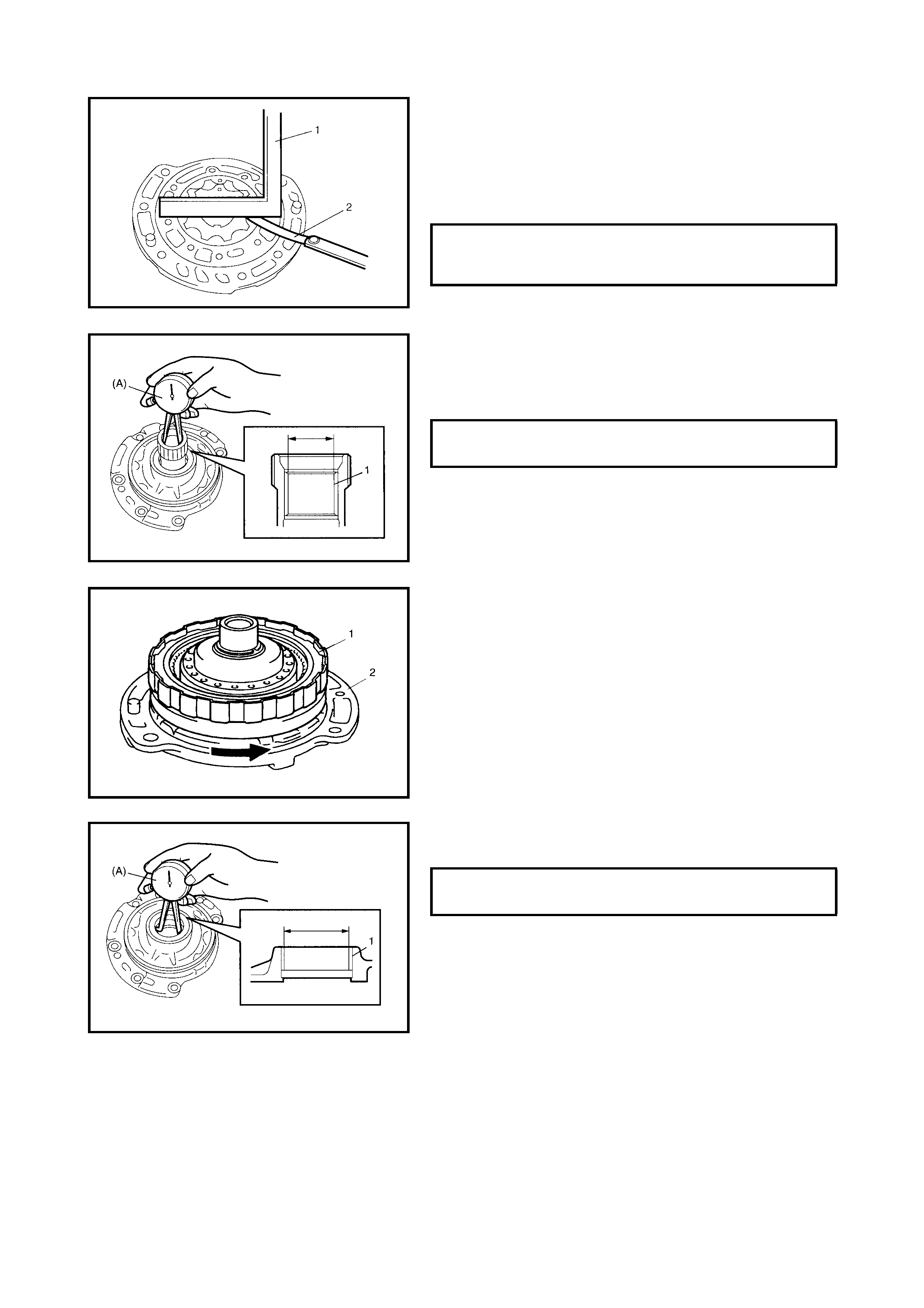
3. Check the side clearance of both gears.
Using a straightedge (1) and a feeler gauge (2),
measure the side clearance between the gears and
pump body.
If the clearance exceeds the standard value, replace
the oil pump assembly.
4. Using special tool 09900-20605 (A), measure the
stator shaft bush (1) bore.
If the stator shaft bush bore measure is out of specifi-
cation, replace the oil pump assembly with a new one.
5. Install the dir ect clutch ass embly (1) to the stator shaft
assembly (2), ensuring that the direct clutch assembly
turns smoothly.
If uneven rotation or noise are found in the oil pump
assembly, replace the oil pump assembly with a new
one. This check s hould also be done t o the input shaft
assembly. Replace input shaft assembly if necessary.
6. Using speci al tool 09 900-20 605 (A), measure oi l pump
body bush bore.
If the oil pump body bush bore measurement is out of spec-
ification, replace the oil pump assembly with a new one.
The torque converter also needs to be checked. Replace
the torque converter, if necessary.
SIDE CLEARANCE BETWEEN GEARS
AND OIL PUMP BODY STANDARD 0.02 - 0.05 mm
STATOR SHAFT BUSH BORE
STANDARD 18.4 24 - 18 .450 mm
OIL PUMP BODY BUSH BORE
STANDARD 38.113 - 38.138 mm
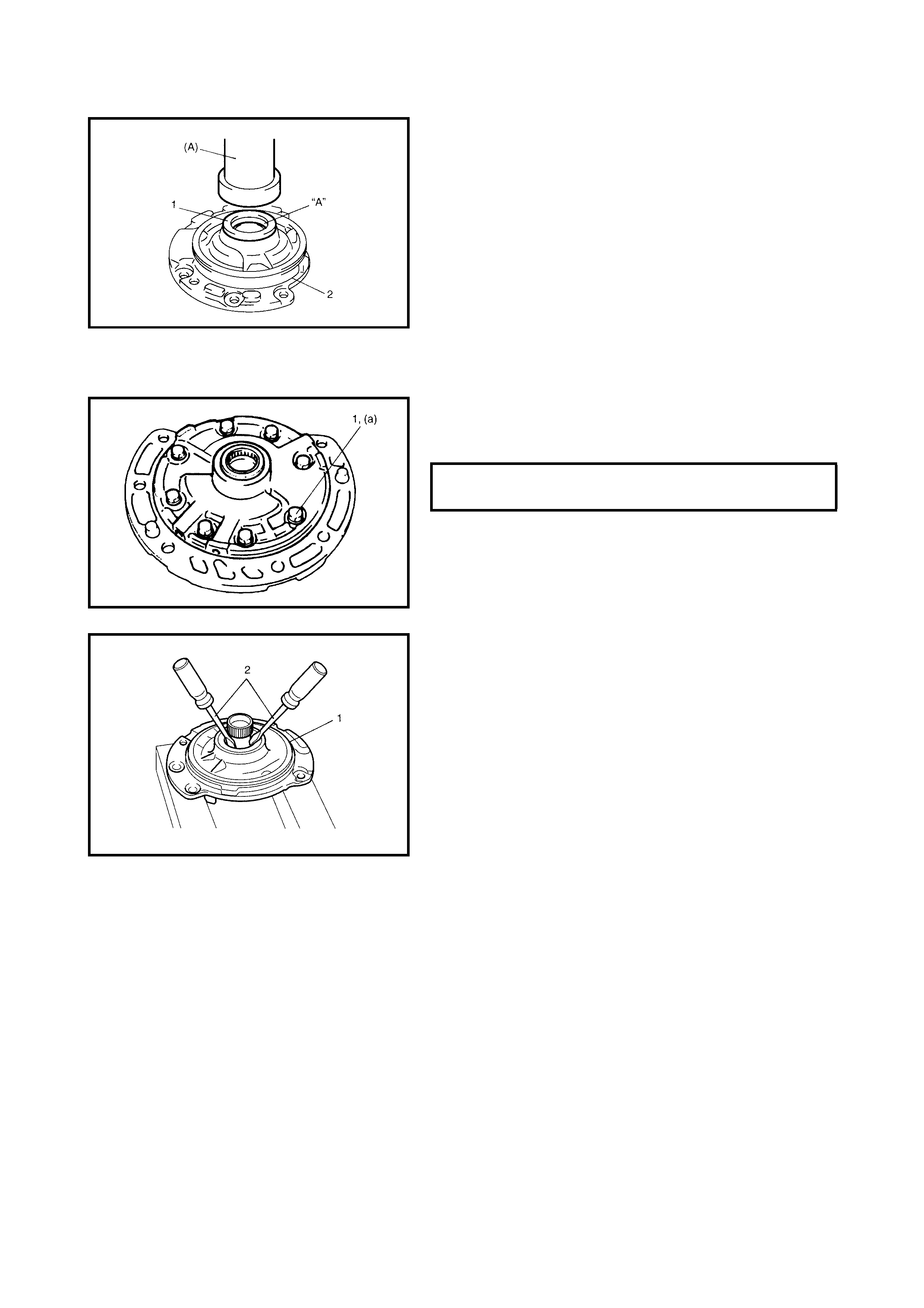
ASSEMBLY
1. Install a new oil seal (1) to the oil pump body (2).
Use special tool, 09913-85210 (A), and hammer to
install. Apply grease to the seal lip.
“A”: Lithium grease
2. Install the driven gear and drive gear to the oil pump
body after applying A/T fluid.
3. Install the stator shaft assembly to the oil pump body
and tighten the 8 pump subassembly bolts (1) to speci-
fication.
4. After apply ing A/T f luid to a new O-r ing, install it to the
oil pump body (1).
CAUTION: Do not damage the oil seal with slotted
screw driver.
5. Check the drive gear for smooth rotation using slotted
a screw driver (2).
OIL PUMP SUB-ASSEMBLY BOLTS (a)
TORQUE SPECIFICATION 10 Nm
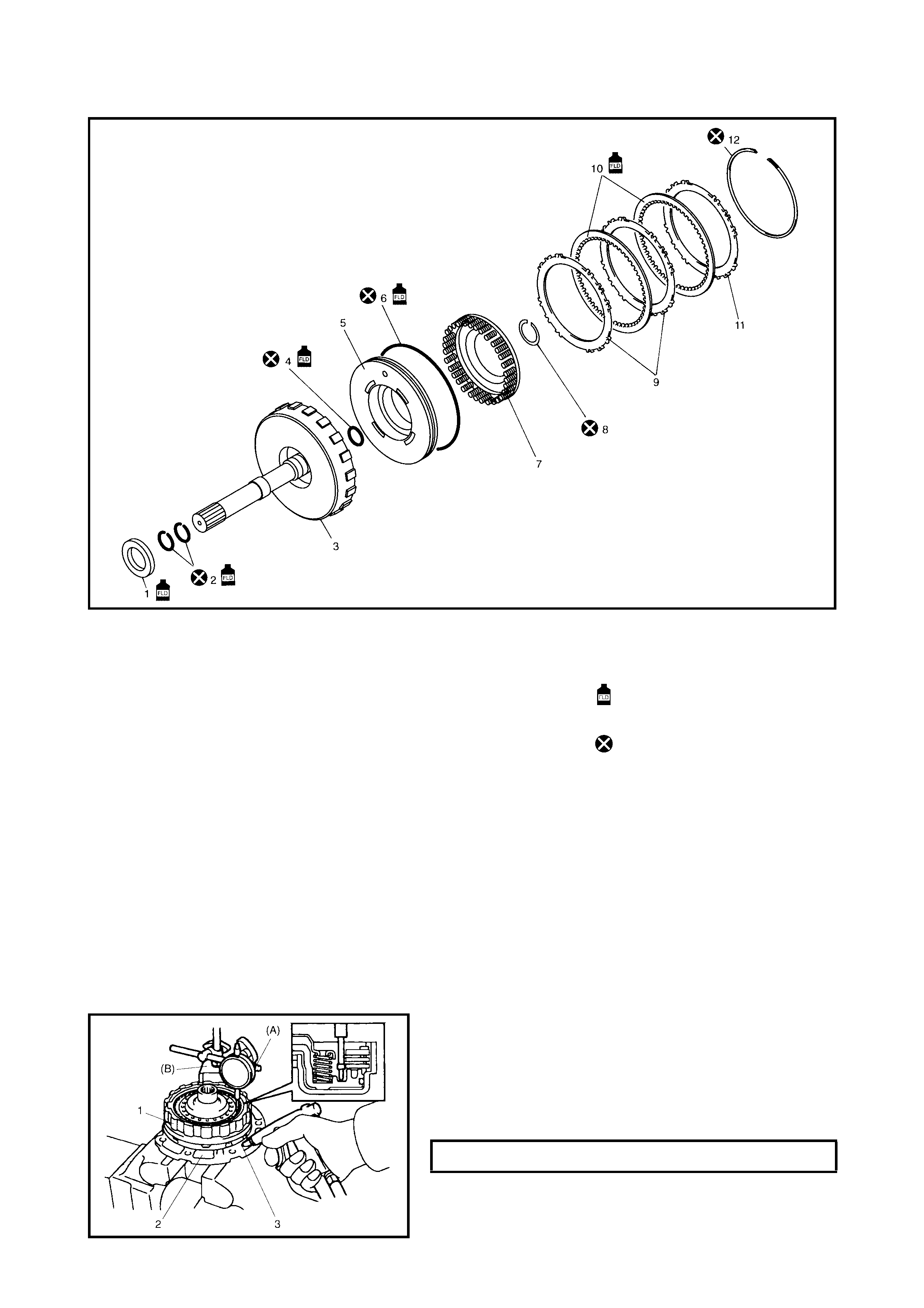
DIRECT CLUTCH
Legend
CAUTION: When component parts of the forward
clutch (na mely clutch disc, retaining plate and /or se pa-
rator plate) have been replaced, learned contents,
which have been stored in the TCM memory by execut-
ing learning control, should be initialised, refer to
3.12 TRANSMISSION CONTROL MODULE - LEARNING
CONTROL INITIALISATION in this Section.
Neglectin g this init ialis atio n may ca u se ex ces sive shift
shock.
PRELIMINARY CHECK
1. Install the direct clutch assembly (1) to the oil pump
assembly (2), blow air (400 – 800 kPa) through the oil
hole (3) of the oil pump assembly with special tool,
09900-20607 (A) and 09900-207 0 (B) attached on the
upper s urface of the d irect clutch piston, and me asure
the piston stroke of the direct clutch.
If the piston stroke exceeds the specified value, disassem-
ble, inspect and replace inner parts.
1. Input shaft front thrust
bearing 6. Outer O-ring 11. Direct clutch retaining plate
7. Direct clutch return spring
subassembly 12. Plate snap ring
2. Input shaft seal ring Apply automatic transaxle
fluid.
3. Input shaft subassembly 8. Shaft snap ring
4. Inner O-ring 9. Direct clutch separator plate Do not reuse.
5. Direct clutch piston 10. Direct clutch disc
DIRECT CLUTCH PISTON STROKE 0.4 - 0.7 mm
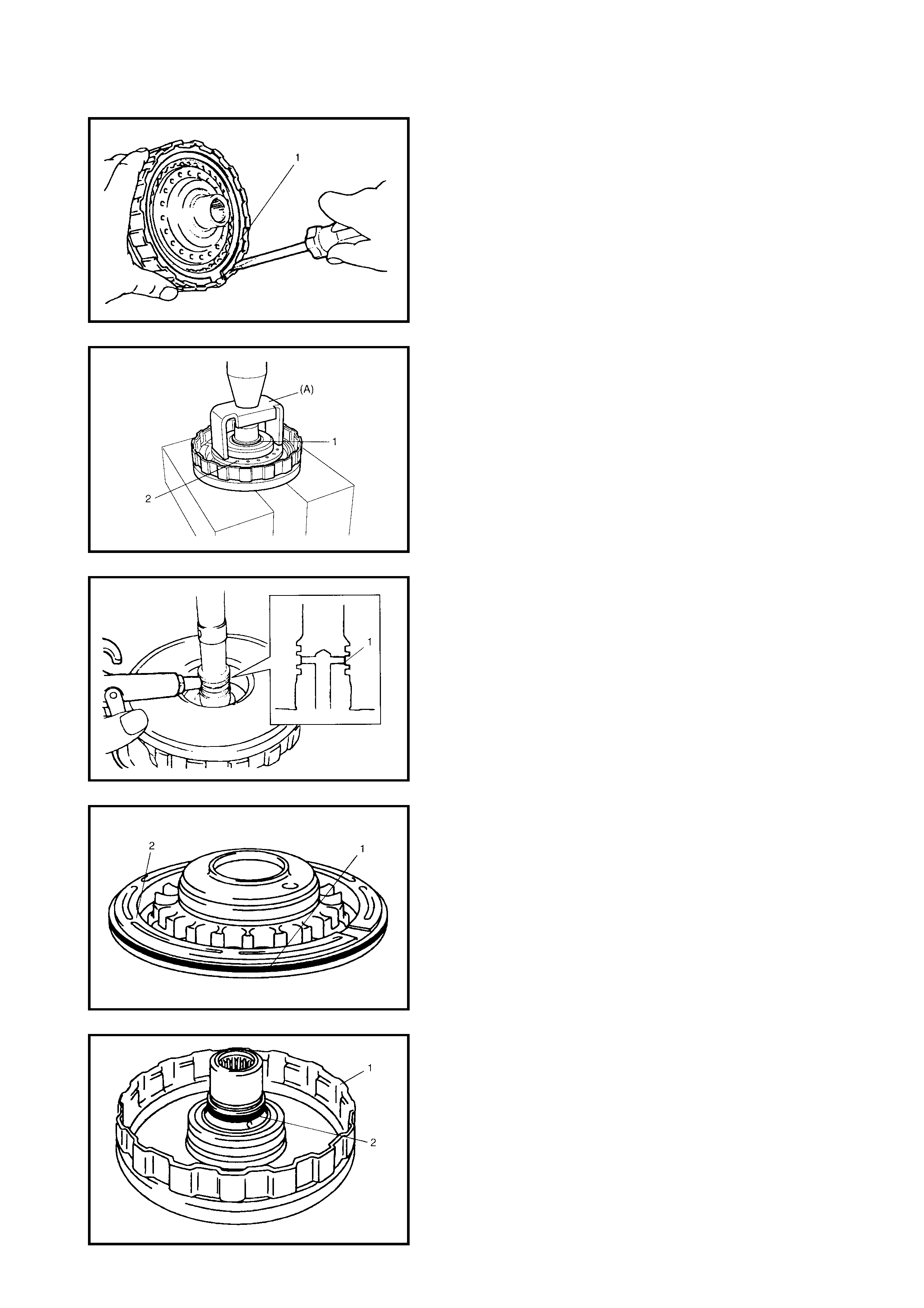
DISASSEMBLY
1. Remove the plate snap ring (1), then remove the direct
clutch retaining plate, discs and separator plates.
CAUTION: Do not press direct clutch return spring
subassembly in more than 0.7 mm.
Excessive compression may cause damage to the
direct clutch return spring subassembly and/or piston.
2. Using special tool, 09926-98310 (A) and hydraulic
press, remove the shaft snap ring (1).
3. Remove the direct clutch return spring assembly (2).
4. To ass ist the remova l of the clutc h piston, use a finger
to block the oil hole (1), then apply compressed air
(400 – 800 kPa) to the opposite hole.
5. Remove the outer O-ring (1) from the direct clutch
piston (2).
6. Remove the inner O-ring (2) from the input shaft
assembly.
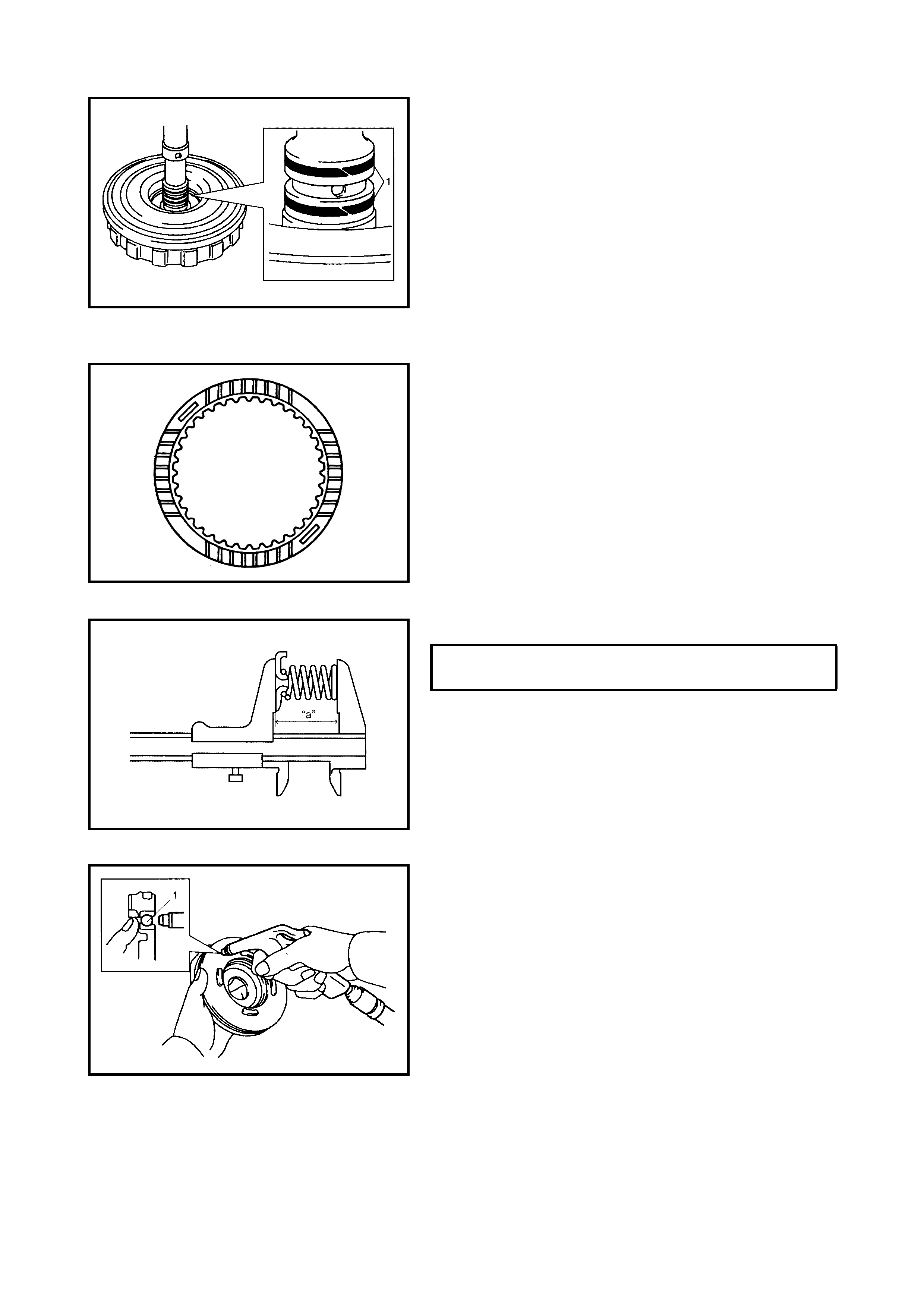
7. Remove the input shaft seal rings (1).
INSPECTION
Clutch Discs, Plates And Retaining Plate
Check that the sliding surfaces of discs, separator plates
and retaining plate are not worn hard or burnt. If necessary,
replace.
NOTE:
• If the disc lining is flaking or discoloured, replace all
discs.
• Before assembling new discs, soak them in A/T fluid
for at least two hours.
Direct Clutch Return Spring Subassembly
Measure the free length of direct clutch return spring.
NOTE:
• Do not apply excessive force when measuring the
spring free length.
• Perform the measurement at several points.
Direct Clutch Piston
Shake the direct clutch piston lightly and ensure that the
check ball (1) is not stuc k. Blow low-p ressure ai r (Max 100
kPa) to the check ball to ensure there is no air leakage.
ASSEMBLY
Reverse disassembly procedure for assembly, noting the
following points.
• Use a new seal ring and O- ring. Appl y A/T flui d before
installation.
FREE LENGTH OF DIRECT CLUTCH
RETURN SPRING (a) 36.04 mm
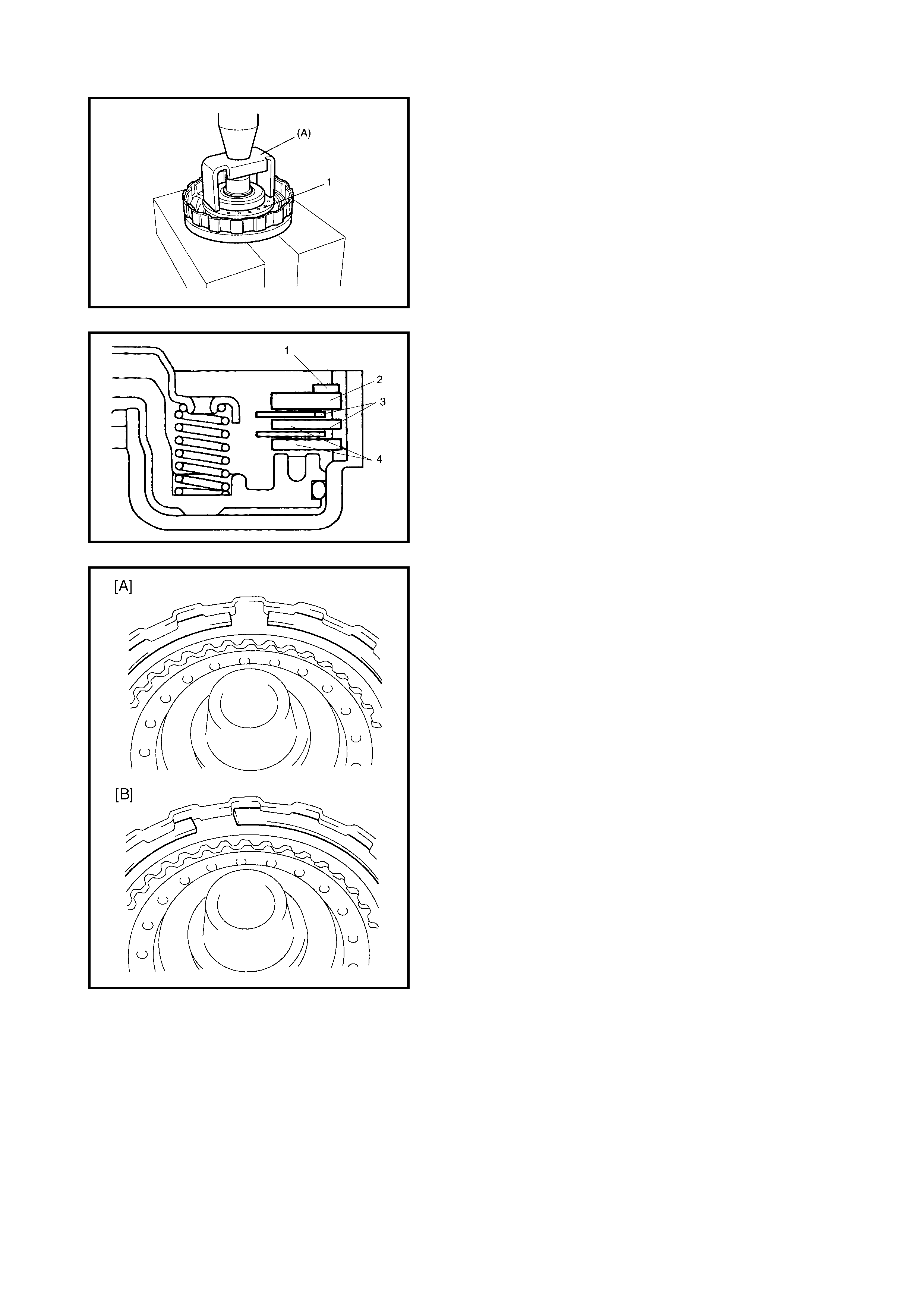
• Do not damage the direct clutch return spring subas-
sembly (1) and piston by pressing in the direct clutch
return spring subassembly more than 0.7 mm past its
original installation position Use special tool
09926098310 (A) to install the direct clutch return
spring sub as se mbl y.
• App ly A/ T fluid to the direc t clutch s eparator pl ates (4),
discs (3) and retaining plate (2).
• Install the direct clutch separator plates (4) discs (3)
retaining plate (2) and snap ring (1) to the input shaft
subassembly.
• Install the plate snap ring so that both ends are posi-
tioned correctly as shown in the figure.
[A] - Correct
[B] - Incorrect
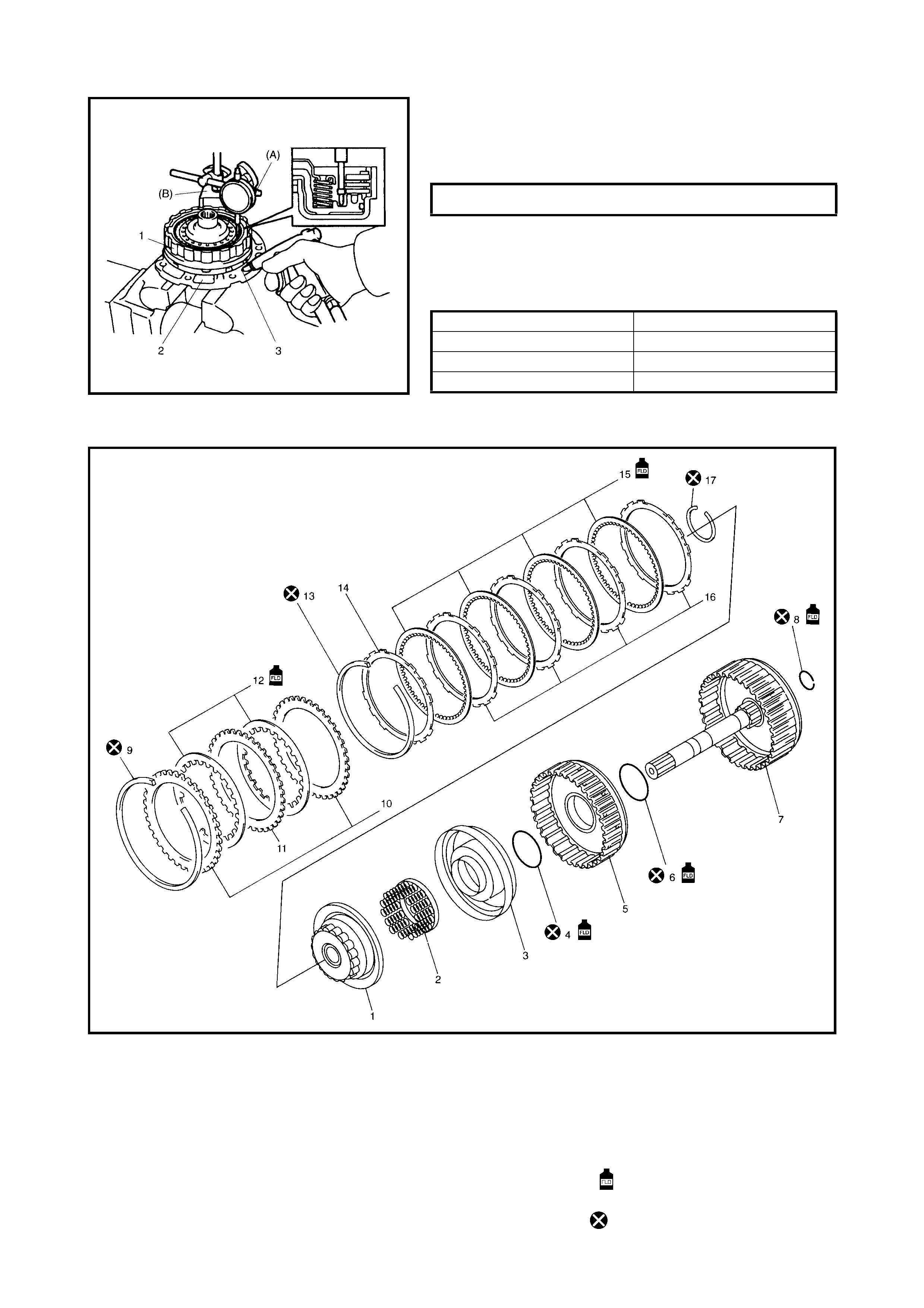
• After assembly, measure the direct clutch (1) piston
stroke using special tools 09900-20607 (A) and 09900-
20701 (B) by blowing low-pressure air through the oil
pump assembly (2) oil hole (3).
When the piston stroke is out of specification, select the
direct clutch retaining plate with a suitable thickness from
the list below and replace it.
Available direct clutch retaining plate thickness
FORWARD AND REVERSE CLUTCH
Legend
DIRECT CLUTCH PISTON STROKE 0.4 - 0.7 mm
THICKNESS IDENTIFICATION MARK
3.0 mm 1
3.2 mm 2
3.4 mm 3
1. Forward clutch balancer 8. Inter mediate shaft seal ring 14. Forward clutch retaining plate
2. Forward clutch return sp ring
subassembly 9. Reverse clutch plate snap
ring 15. Forward clutch disc
16. Forward clutch separator
plate
3. Forward clutch piston 10. Reverse clutch retaining plate
4. Forward clutch piston O-ring 11. Reverse clutch separator
plate 17. Balancer snap ring
Apply automatic transaxle
fluid.
5. Forward clutch drum
6. Forward clutch drum O-ring 12. Reverse clutch disc
7. Intermediate shaft
subassembly 13. Forward clutch plate snap
ring Do not reuse.
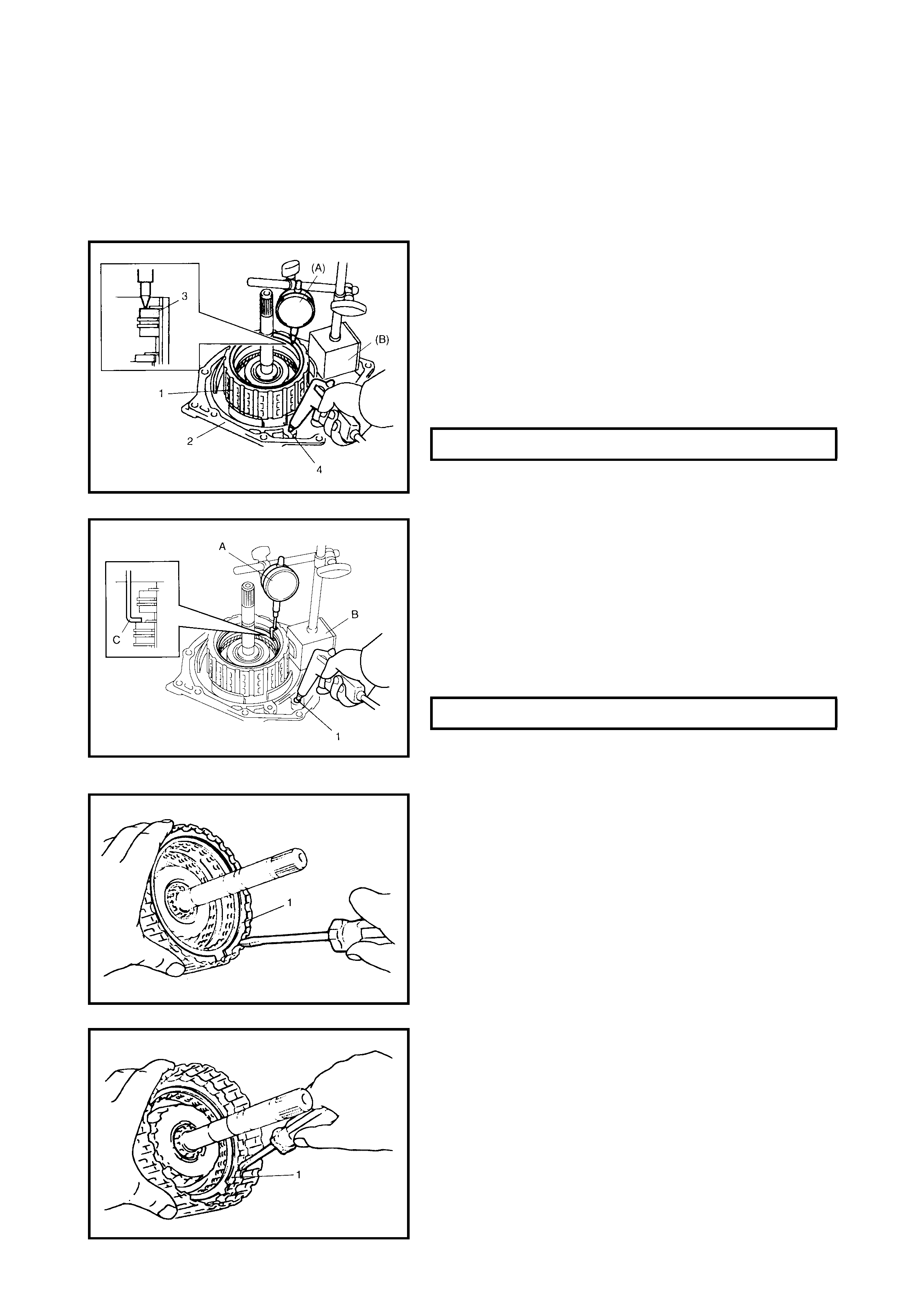
CAUTION: When t he co mpo nent p ar ts of the for war d clu tch (cl utc h di sc, ret a in ing plate an d/o r separa-
tor plate ) have been replaced , learned contents, which have be en stored in t he TCM memory by exe-
cuting learning control, should be initialised, refer to 3.12 TRANSMISSION CONTROL - LEARNING
CONTROL INITIALISATION in this section.
Neglecting this initialisation may cause excessive shift shock
.
PRELIMINARY CHECK
1. Install the forward and reverse clutch assembly (1) to
the transaxle rear cover (2). Attach special tools
09900-20607 (A) and 09900-20701 (B) to the upper
surface of the reverse clutch retaining plate (3).
Blow compressed air (400 – 800 kPa) through the oil
hole (4) of the transaxle rear cover and measure the
reverse clutch piston stroke.
If the pist on strok e excee ds the sp ecified va lue, di sas-
semble, inspect and replace inner parts.
2) Blow compressed air (400 – 800 kPa) through the
oil hole (1) of the transaxle rear cover with special
tool 0 990 0- 20 607 ( A ), 0 990 0- 20 701 ( B ) an d 0 995 2-
06020 (C) attached on the upper surface of forward
clutch retaining plate, and measure the forward
clutch piston stroke.
If the piston stro ke exce eds th e speci fied va lue, dis-
assemble, inspect and replace inner parts.
DISASSEMBLY
1. Remove the reverse clutch plate snap ring (1) and
remove the reverse clutch retaining plate, discs and
separator plates from the intermediate shaft subas-
sembly.
2. Remove the forward clutch plate snap ring (1) and
remove the forward clutch retaining plate, discs and
separator plates from the forward clutch drum.
REVERSE CLUTCH PISTO N STROKE 0.86 - 1.26 mm
FORWARD CLUTCH PISTON STROKE 1.30 - 1.50 mm
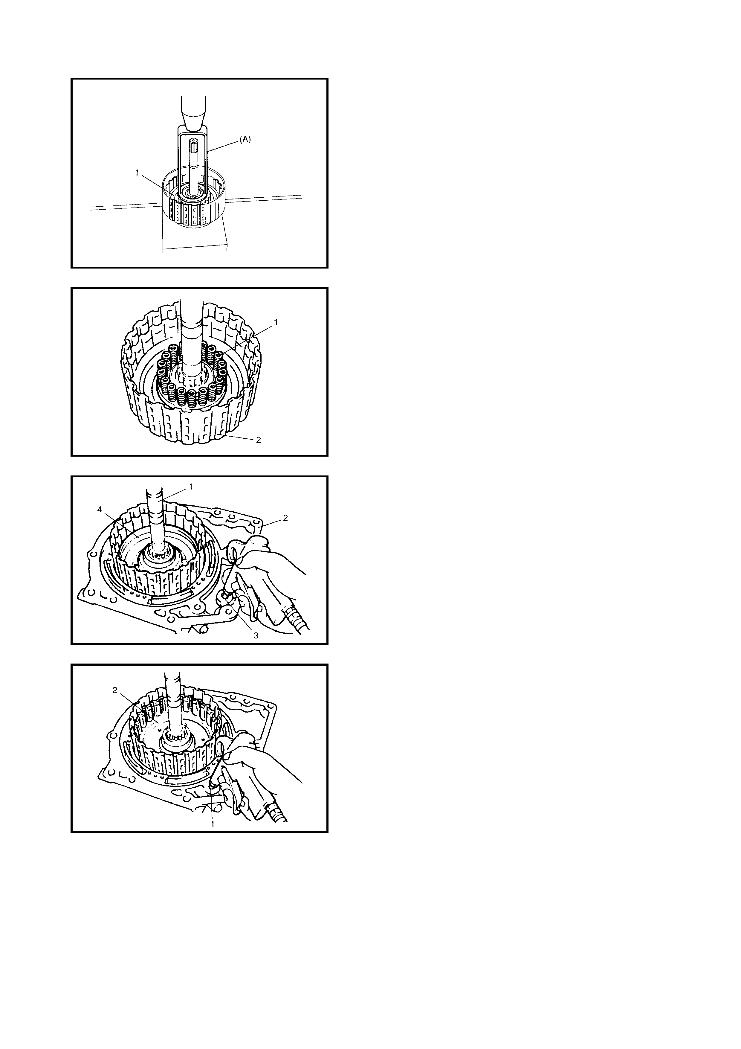
CAUTION: Do not press the forward clutch return
spring subass embly in more than 1.5 mm.
Excessive compression may cause damage to the
return spring subassembly and/or balancer.
3. Remove the balancer snap ring using special tool
09926-97610 (A) and a hydraulic press.
4. Remove the forward clutch balancer (1).
5. Remove the forward clutch return spring subassembly
(1) from the intermediate shaft assembly (2).
Install the intermediate shaft subassembly (1) to the tran-
saxle rear cover (2). Apply compressed air (400 – 800 kPa)
to oil hole (3) of the transaxle rear cover to remove the for-
ward clutch piston (4).
6. Apply compressed air (400 – 800 kPa) to the oil hole
(1) of the transaxle rear cover to remove the forward
clutch drum (2).
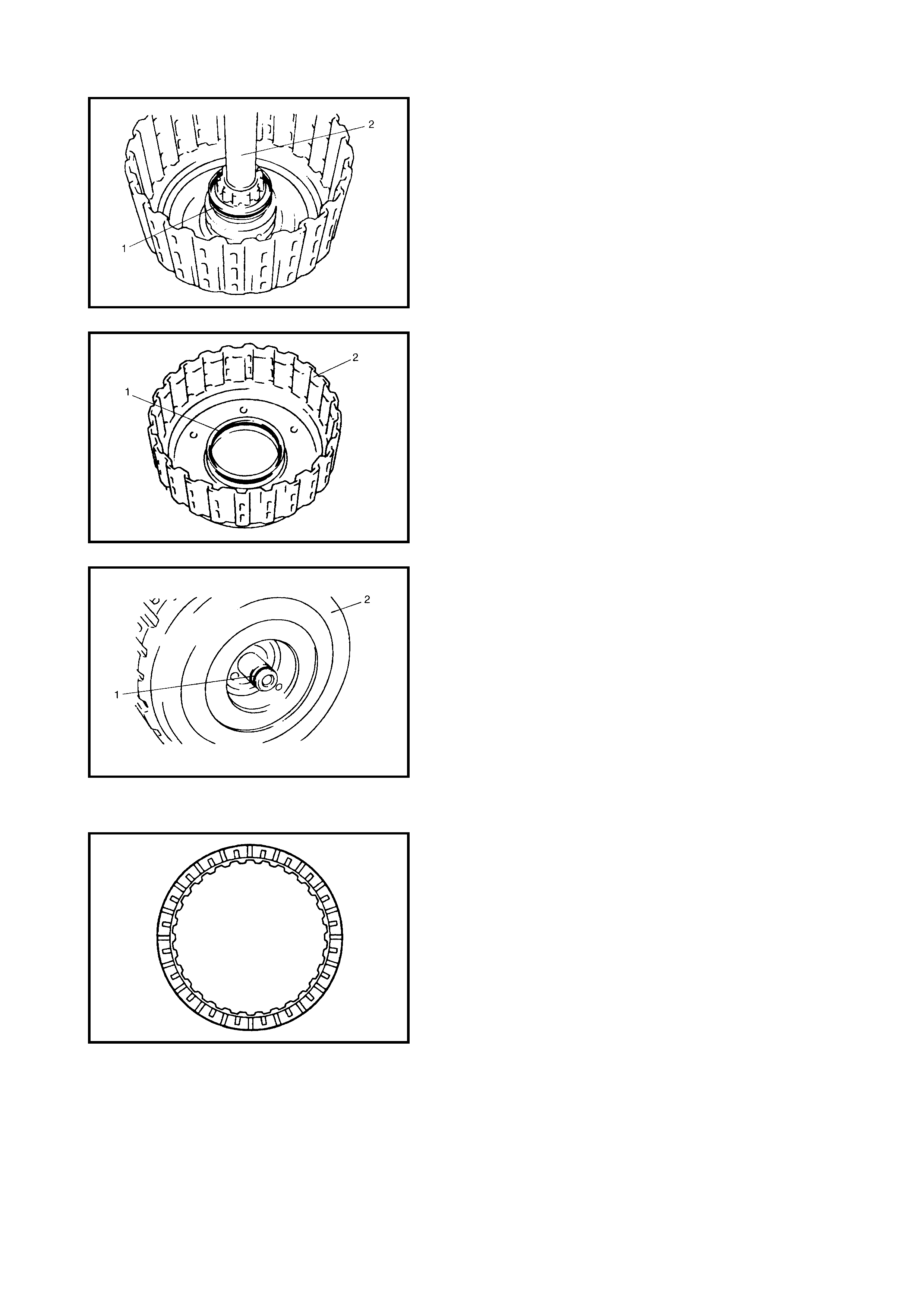
7. Remove the forward clutch piston O-ring (1) from the
intermediate shaft subassembly (2).
8. Remove the forward clutch drum O-ring (1) from the
forward clutch drum (2).
9. Remove the intermediate shaft seal ring (1) from the
intermediate shaft subassembly (2).
INSPECTION
Clutch Discs, Separator Plates and Retaining Plate
Check that the sliding surfaces of discs, separator plates
and retaining plate are not worn hard or burnt. If necessary,
replace.
NOTE:
• If the disc lining is flaking or discoloured, replace all
discs.
• Before assembling new discs, soak them in A/T fluid
for at least two hours.
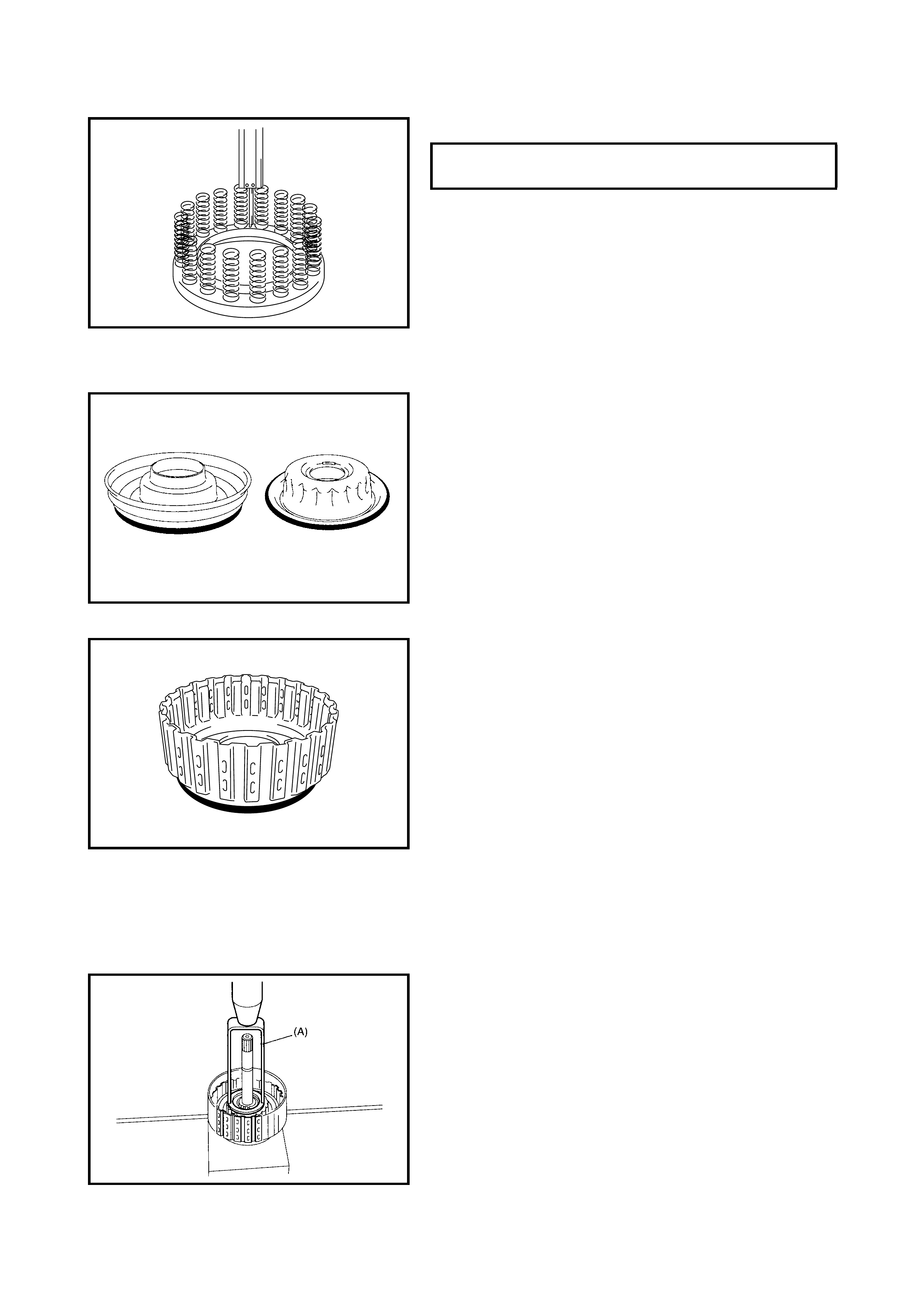
Forward Clutch Return Spring Subassembly
Measure free length of forward clutch return spring.
NOTE:
• Do not apply excessive force when measuring the
spring free leng th.
• Measure at several points.
Forward Clutch Piston Lip and Forward Clutch
Balancer Lip
Check ea ch lip for wear, d eformation, cuts, an d/or harden-
ing. If necessary, replace.
Forward Clutch Drum Lip
Check ea ch lip for wear, d eformation, cuts, an d/or harden-
ing. If necessary, replace.
ASSEMBLY
Reverse disassembly procedure for assembly, noting the
following points.
• Before assembling, apply A/T fluid to component parts.
• Replace O-rings and seal ring with new ones.
• Install the forward clutch return spring subassembly
and balancer using special tool 09926-97610.
Do not damage the forwa rd clutc h r etu rn spri ng s uba s-
sembly and balancer by pressing it in more than 1.5
mm passed its original installation position.
FREE LENGNTH OF FORWARD
CLUTCH RETURN SPRING 23.04 mm
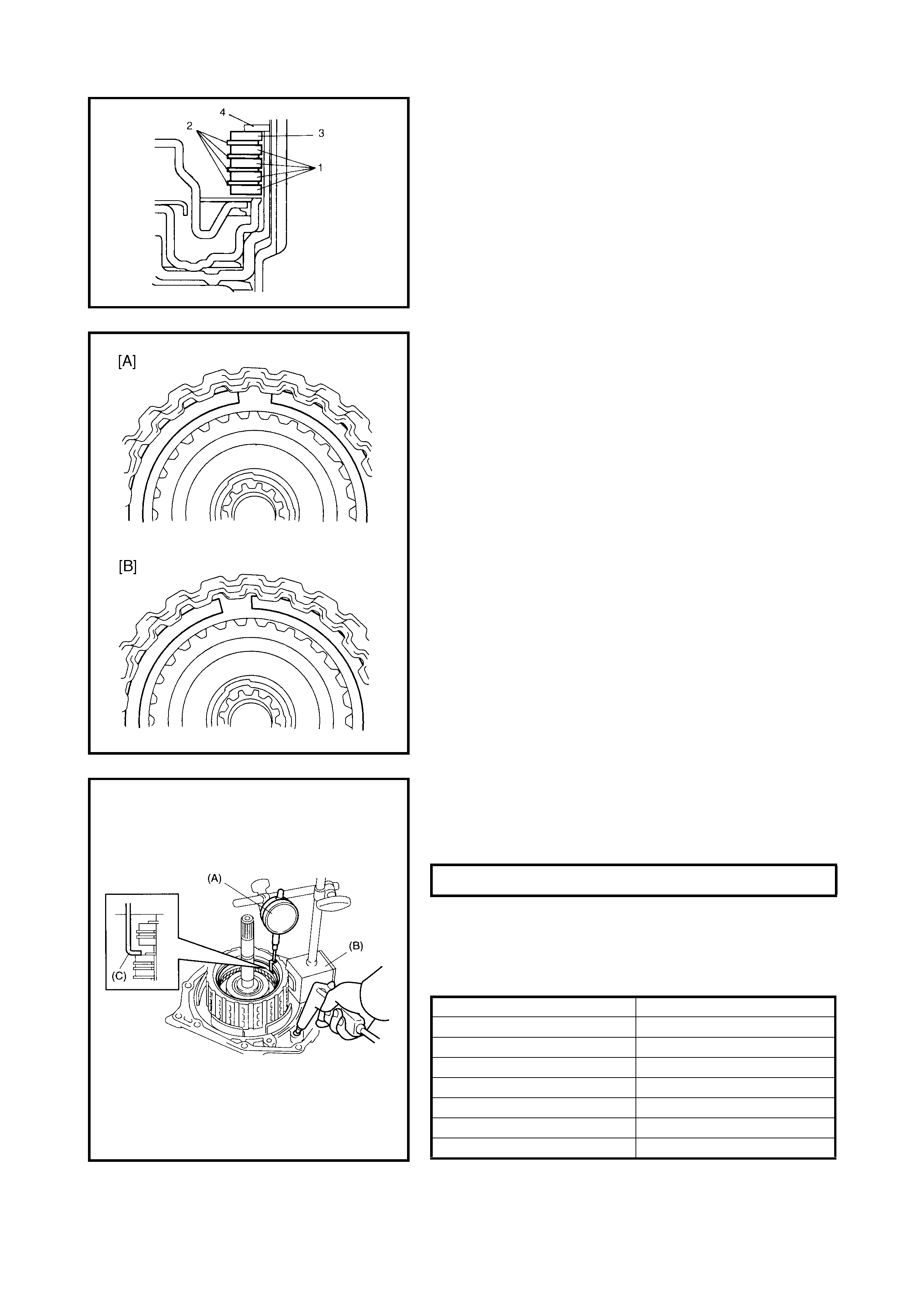
• Apply A/T fluid to the forward clutch separator plates
(1), discs (2 ) and retainin g plate (3) .
• Ins tall the f orward c lutch s eparator p lates (1), d iscs (2)
and retaining plate (3), then the snap ring (4) to the for-
ward clutch drum.
• Install the forward clutch plate snap ring so both ends
are positioned in the correct location as shown in the
figure.
A - Correct
B - Incorrect
• Measure the forward clutch piston stroke in the same
manner as PRELIMINARY CHECK described previ-
ously using special tools 09900-20607 (A), 09900-
20701 (B) and 09952-06020 (C).
When the piston stroke is out of specification, select the
forward clutch retaining plate with the correct thickness
from the list below and replace it.
Available forward clutch retaining plate thickness
FORWARD CLUTCH PISTON STROKE 1.30 - 1.50 mm
THICKNESS IDENTIFICATION MARK
3.0 mm 1
3.1 mm 5
3.2 mm 2
3.3 mm 6
3.4 mm 3
3.5 mm 7
3.6 mm 4
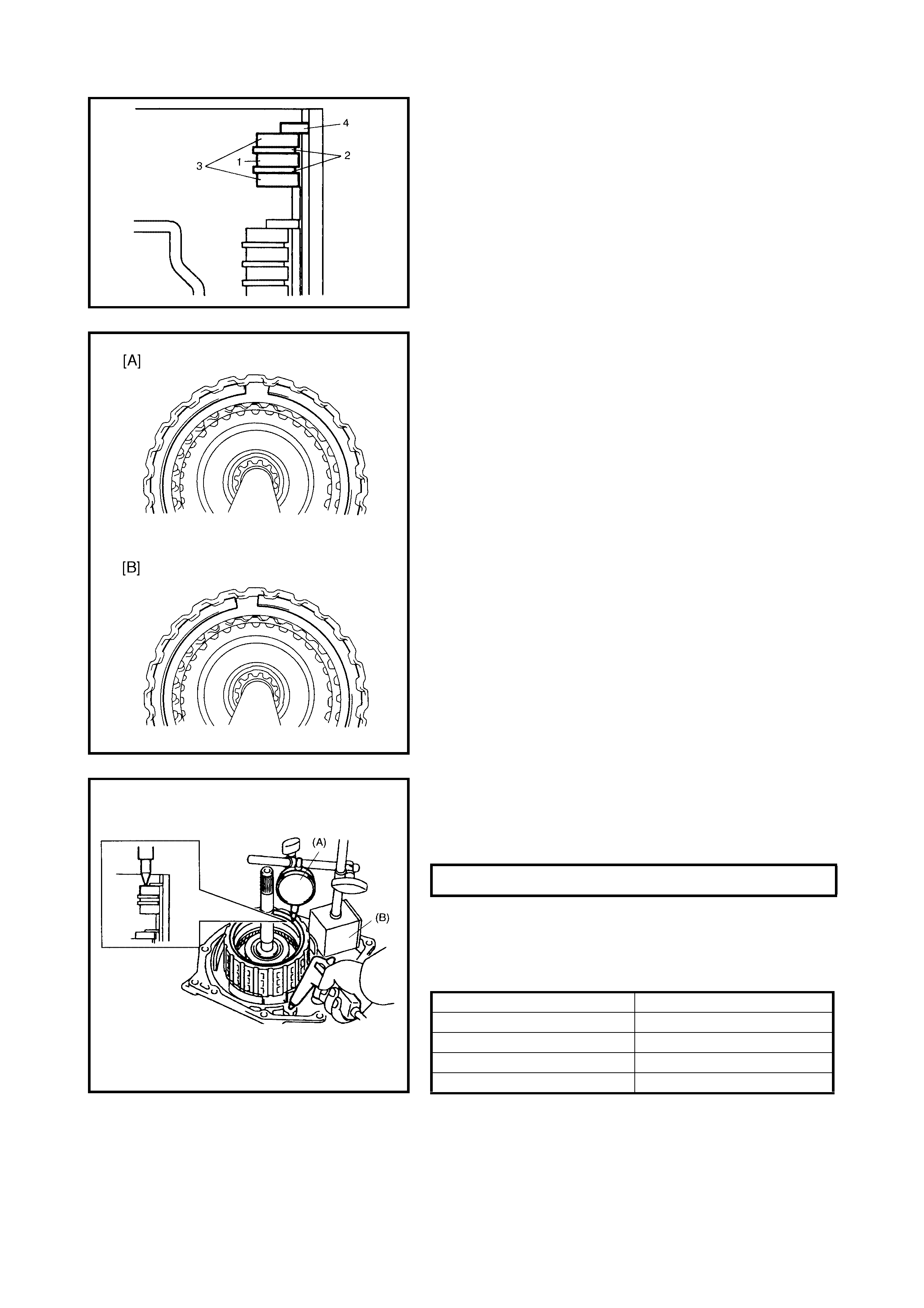
• App ly A/ T f luid to the r ev ers e cl utch s epara tor pl ate ( 1)
discs (2) and retaining plate (3).
• Install the reverse clutch separator plate (1) discs (2)
retaining pl ate ( 3) and snap r i ng (4) to th e in ter me dia te
shaft subassembly.
• Install the reverse clutch plate snap ring so that its
ends are po siti oned in th e corre ct locati on as sh own in
the figure.
A - Correct
B - Incorrect
• Measure the reverse clutch piston stroke in the same
manner as PRELIMINARY CHECK described previ-
ously, us ing sp ecial tools 0990 0-206 07 (A) an d 09900-
20701 (B).
When the piston stroke is out of specification, select the
reverse clutch retaining plate with the correct thickness
from the list below and replace it.
Available reverse clutch retaining plate thickness
REVERSE CLUTCH PISTO N STROKE 0.86 - 1.26 mm
THICKNESS IDENTIFICATION MARK
3.0 mm 1
3.2 mm 2
3.4 mm 3
3.6 mm 4
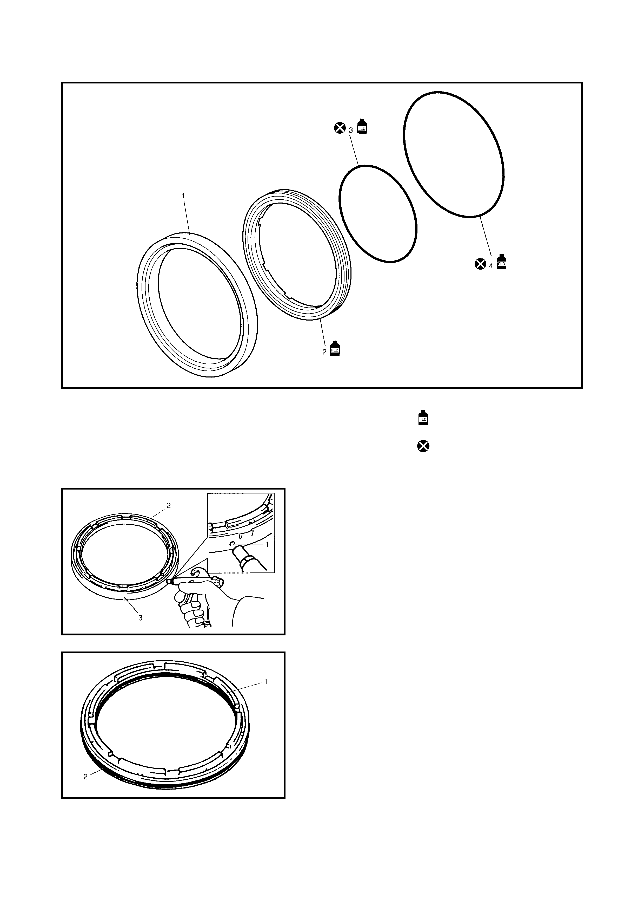
2ND BRAKE PISTON
Legend
DISASSEMBLY
1. Apply compressed air (400 – 800 kPa) to the oil hole
(1) of the 2nd brake cylinder (3) to remove the 2nd
brake piston (2).
2. Remove the inner O-ring (1 ) and the oute r O-rin g (2).
1. 2nd brake cylinder 3. Inner O-ring Apply automatic transaxle
fluid.
2. 2nd brake piston 4. Outer O-ring Do not reuse.
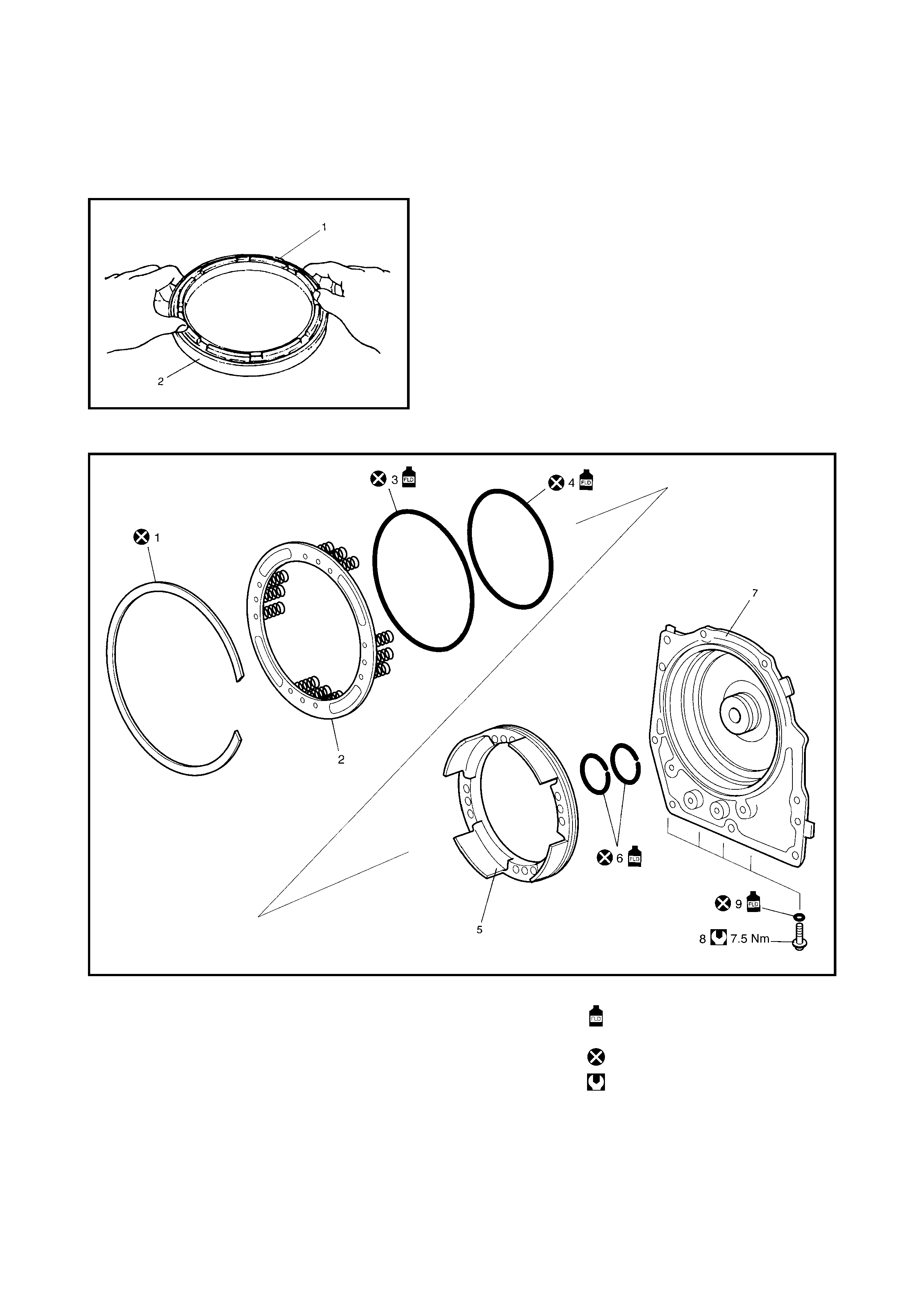
ASSEMBLY
Reverse disassembly procedure for assembly, noting the
following points.
• Use new O- rings. Ap ply A/T f luid to t he O-rin gs before
installation.
• Apply A/T fluid to the 2nd brake piston (1) then install
onto the 2nd brake cylinder.
Do not damage the O-ring when installing the 2nd
brake piston.
TRANSAXLE REAR COVER ASSEMBLY (O/D AND 2ND COAST BRAKE PISTON)
Legend
1. Snap ring 5. O/D and 2nd coast brake
piston Apply automatic transaxle
fluid.
2. O/D and 2nd coast brake
return spring subassembly 6. Rear cover seal ring Do not reuse.
3. O/D and 2nd coast brake
piston front O-ring 7. Transaxle rear cover Tightening torque
8. Rear cover plug
4. O/D and 2nd coast brake
piston rear O-ring 9. Rear cover plug O-ring
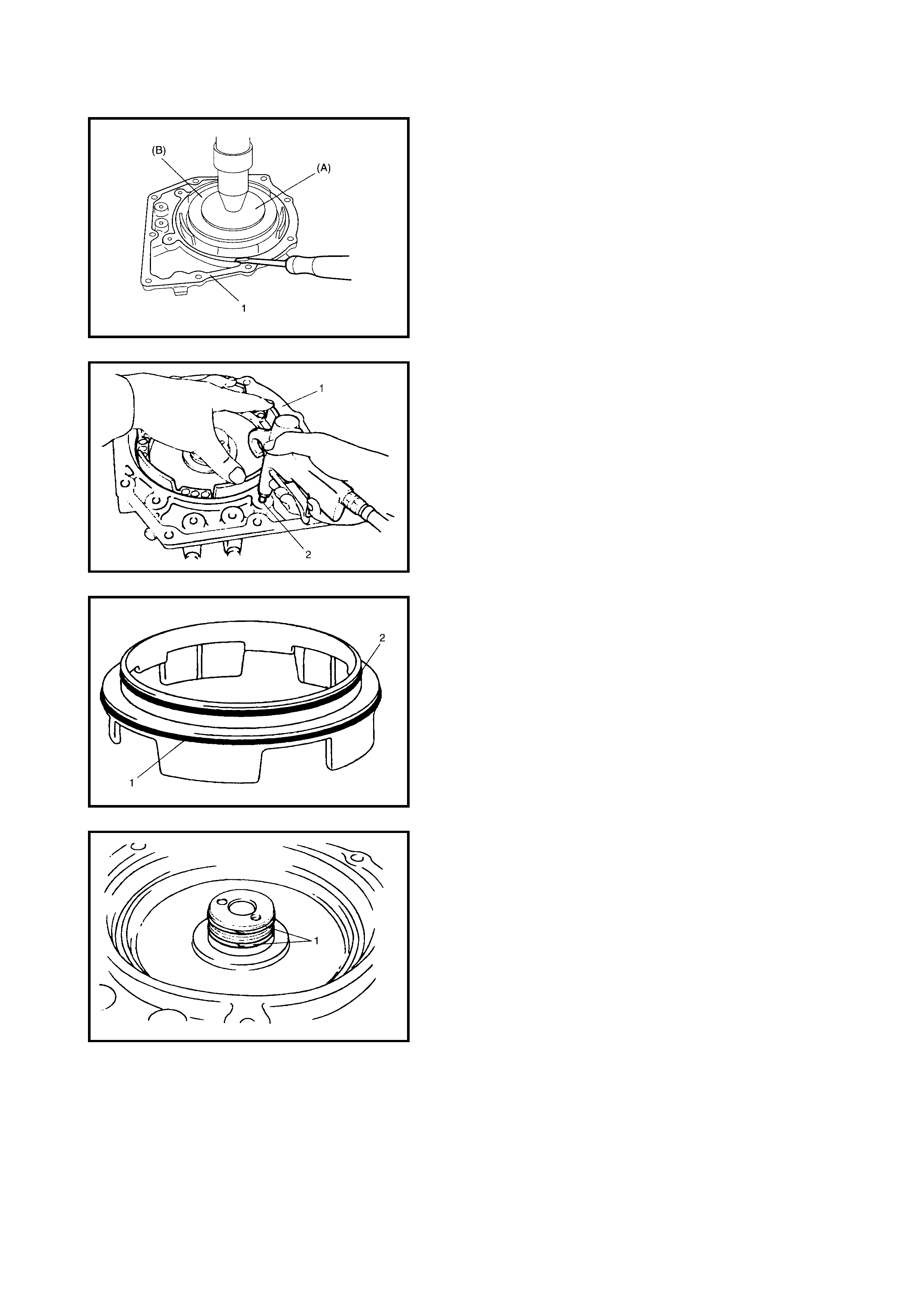
DISASSEMBLY
CAUTION: Do not press the O/D and 2nd coast brake
return spring subassembly in more than 1.0 mm.
Excessiv e compressi on may cause d amage to th e O/D
and 2nd coast brake return spring subassembly and/or
piston.
1. Remove the snap ring from the transaxle rear cover (1)
using spe cial tools 099 26-96030 (A) and 09946-0671 0
(B) and hydraulic press.
2. Remove the O/D and 2nd coast brake return spring
assembly.
3. Apply compressed air (400 – 800 kPa) to the oil hole
(2) of the transaxle rear cover (1) to remove the O/D
and 2nd coast brake piston.
4. Remove the O/D and 2nd coast brake piston front O-
ring (1) and rear O-ring (2).
5. Remove the rear cover seal rings (1).
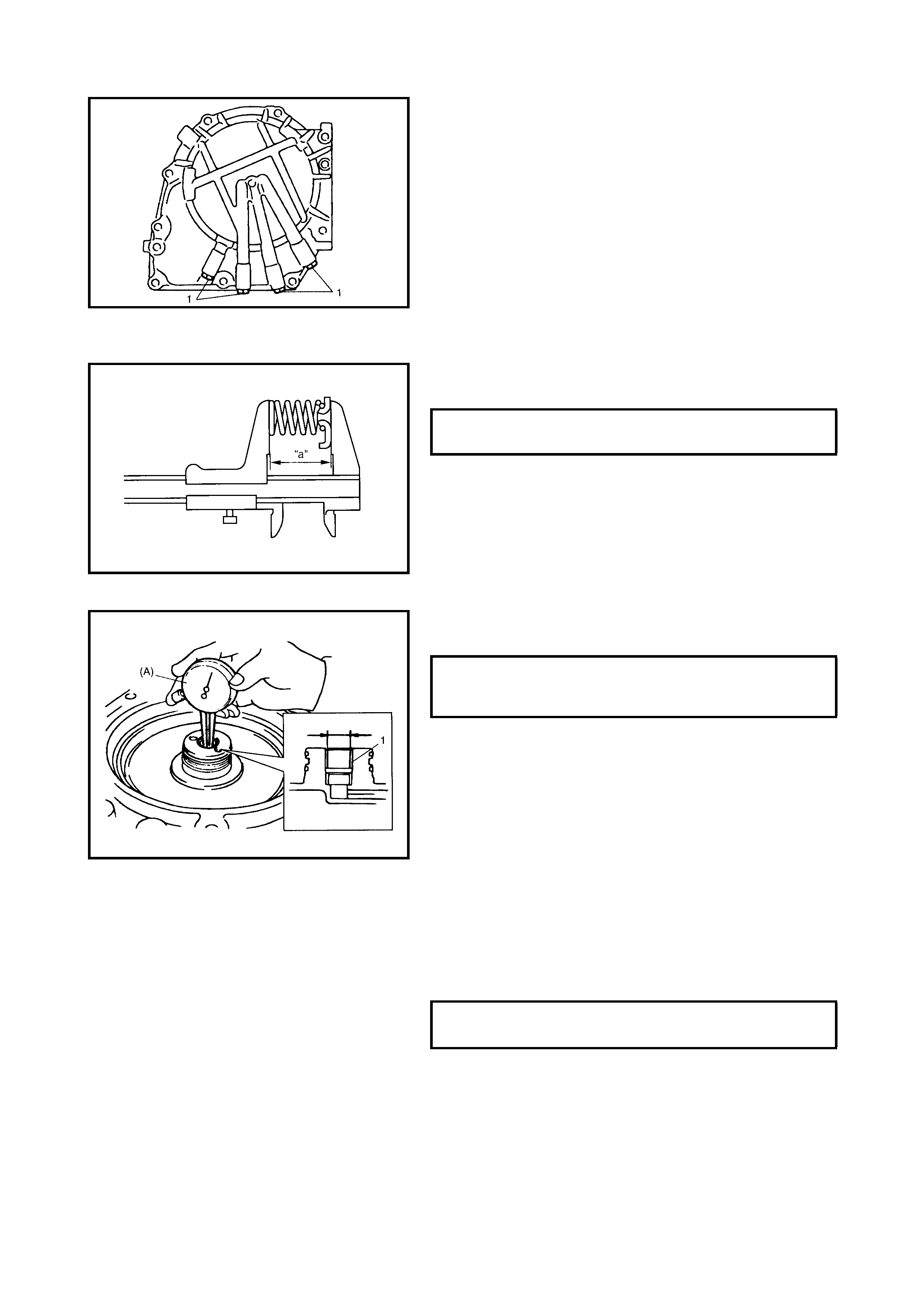
6. Remove the rear cover plugs (1).
INSPECTION
O/D and 2nd Coast Brake Return Spring Subass embly
Measure the free length of the O/D and 2nd coast blake
return spring.
NOTE:
• Do not apply excessive force when measuring the
spring free leng th.
• Measure at several points.
Transaxle Rear Cover Bush
7. Measure the transaxle rear cover bush bore using
special tool 09900-20605 (A).
If the m easure d trans axle re ar cove r bush bor e is out o f
specification, replace the transaxle rear cover with a
new one. During replacement, the intermediate shaft
subassembly also needs to be checked. Replace the
intermediate shaft subassembly, if necessary.
ASSEMBLY
Reverse disassembly procedure for assembly, noting the
following points.
• Use new seal rings and O-rings. Apply A/T fluid to seal
rings and O-rings before installation.
• Tighten the rear cover plugs to specified torque.
FREE LENGTH OF O/D AND 2ND
COAST BRAKE RETURN SPRING (a) 18.99 mm
TRANSAXLE REAR COVER BUSH
BORE STANDARD 13.94 - 14.00 mm
REAR COVER PLUGS
TORQUE SPECIFICATION 7.5 Nm
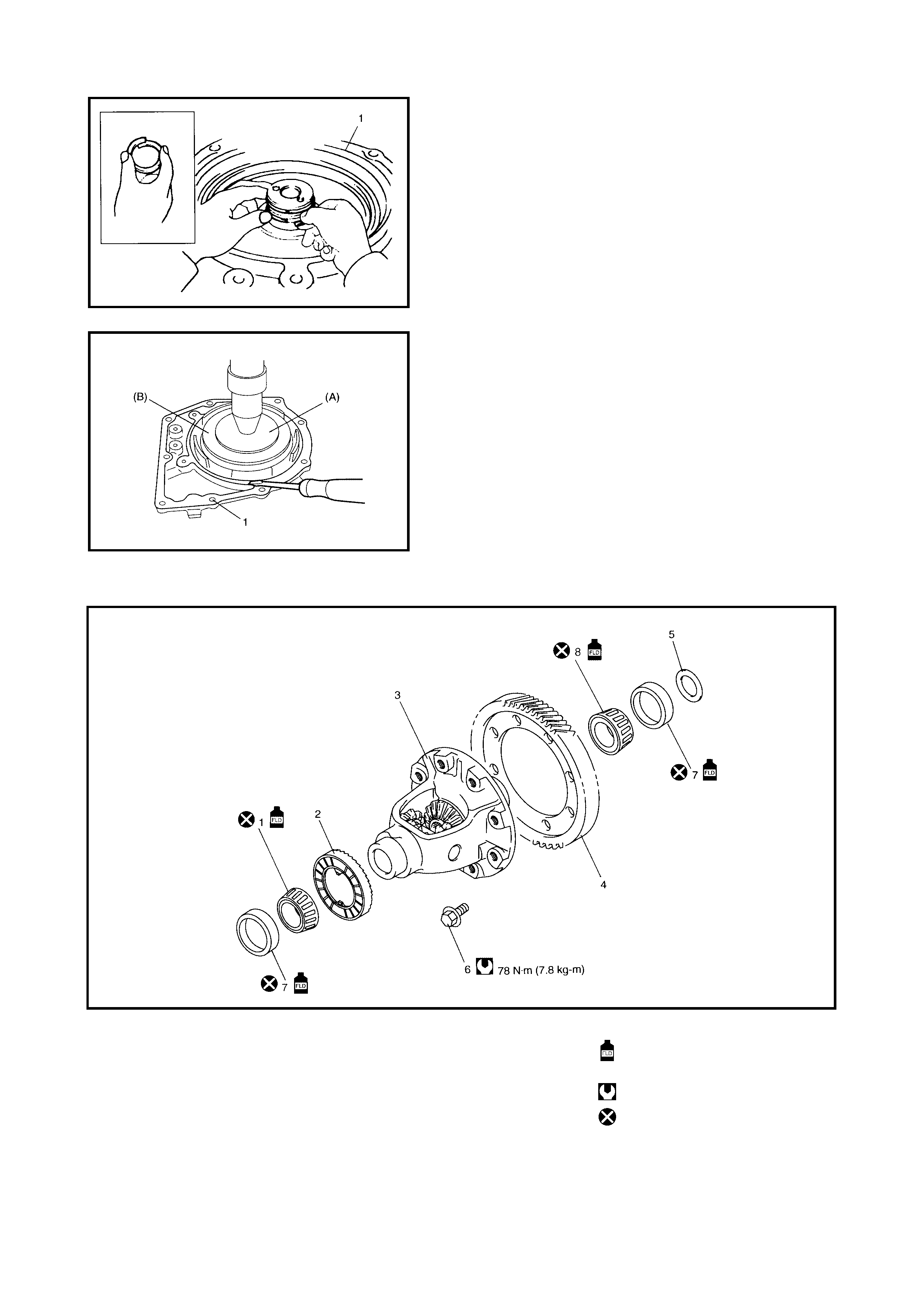
• Apply A/T fluid to the rear cover seal ring before install-
ing to the transax le rear cover. Tighten sea l ring 5 m m
(as shown) before installing.
• Do not open rear cover seal ring too wide to attach.
• Do not damage the O/D and 2nd coast brake return
spring s ubassembly an d piston by pre ssing in the O/ D
and 2nd coast brake return spring subassembly more
than 1.0 mm past its original installation.
Install the O/D and 2nd coast brake return spring sub-
assembly using special tools
09926-96030 (A) and
0994 6-06710 (B) to the transaxle rear co ver (1).
4.5 DIFFERENTIAL ASSEMBLY
Legend
1. Differential side RH bearing 5. Side bearing shim Apply automatic transaxle
fluid.
2. Output shaft speed sensor 6. Final gear bolt
(VSS) drive gear 7. Side bearing cup Tightening torque
3. Differential case subassembly 8. Differential side LH bearing Do not reuse.
4. Final gear
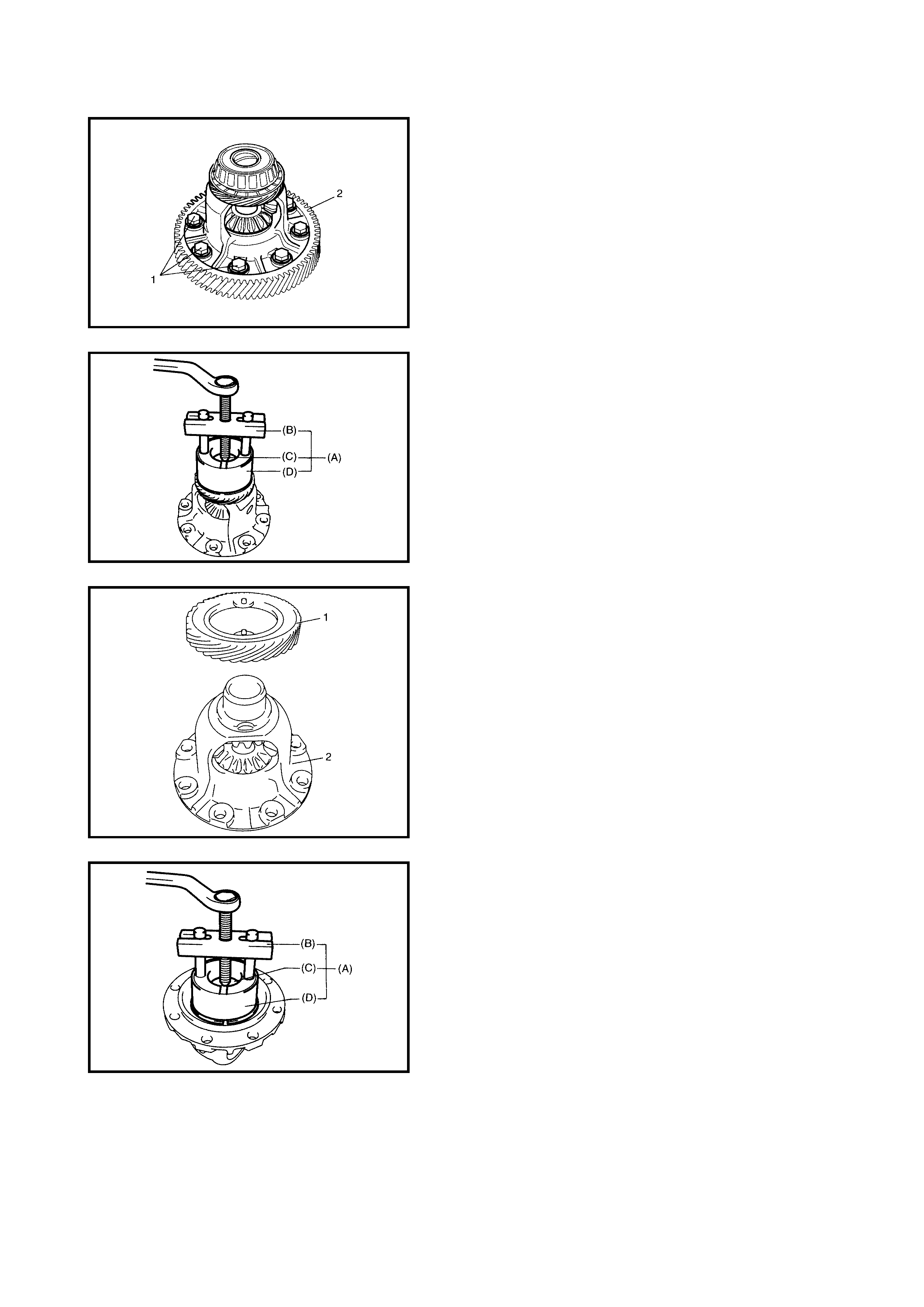
DISASSEMBLY
1. Remove the final gear bolts (1), and the final gear (2).
2. Remove the differential side RH bearing using special
tools 09926-37610 (A), 09926-37610-001 (B), 09926-
37610-003 (C) and 09926-37610-002 (D).
3. Remove the output shaft speed sensor (VSS) drive
gear (1) from the differential case subassembly.
4. Remove the differential side LH bearing using special
tools 09926-37610 (A), 09926-37610-001 (B), 09926-
37610-003 (C) and 09926-37610-002 (D).
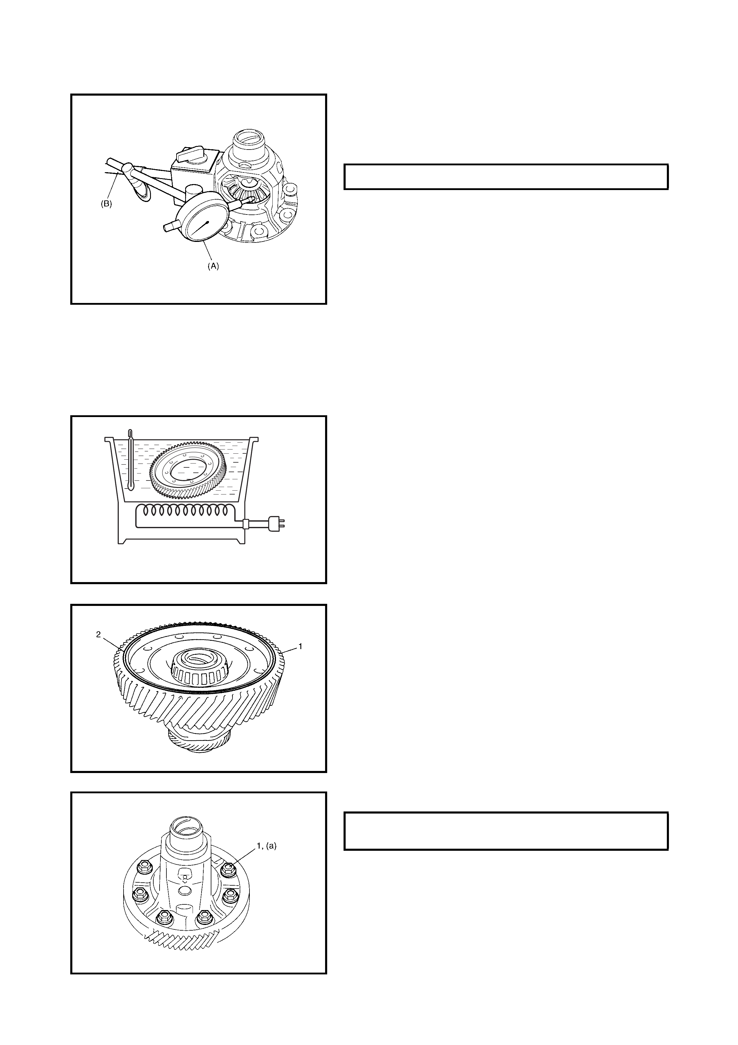
INSPECTION
1. Hold the differential case subassembly in a soft jawed
vice and set special tools
09900-20607 (A) and
0990 0-20701 (B)
as shown.
2. Measure the differential gear thrust play.
3. If the thrust pla y is out of sp ecification, re place the dif-
ferential case subassembly.
ASSEMBLY
WARNING:
• When removing the heated final driven gear out of
the container, use tongs to avoid burning hands.
• While installing the heated final driven gear, use
oven gloves or similar to avoid burning hands.
CAUTION: Do not le ave the final drive n gear in boiling
water for longer than 5 minutes. Overheating the gear
may cause a reduction in gear strength.
1. Place the driven gear in a water container, heat and
remove when the water boils and dry off.
NOTE: After removing the moisture on the final driven gear,
install as quickly as possible.
2. Install the final driven gear (1), with the groove (2)
facing up, to the differential case.
3. Tighten the final gear bolts (1) to the specified torque.
NOTE: To prevent rust, apply A/T fluid to the final driven
gear after installation
DIFFERENTIAL GEAR THRUST PLAY 0.05 - 0.20 mm
FINAL GEAR BOLTS (a)
TORQUE SPECIFICATION 78 Nm
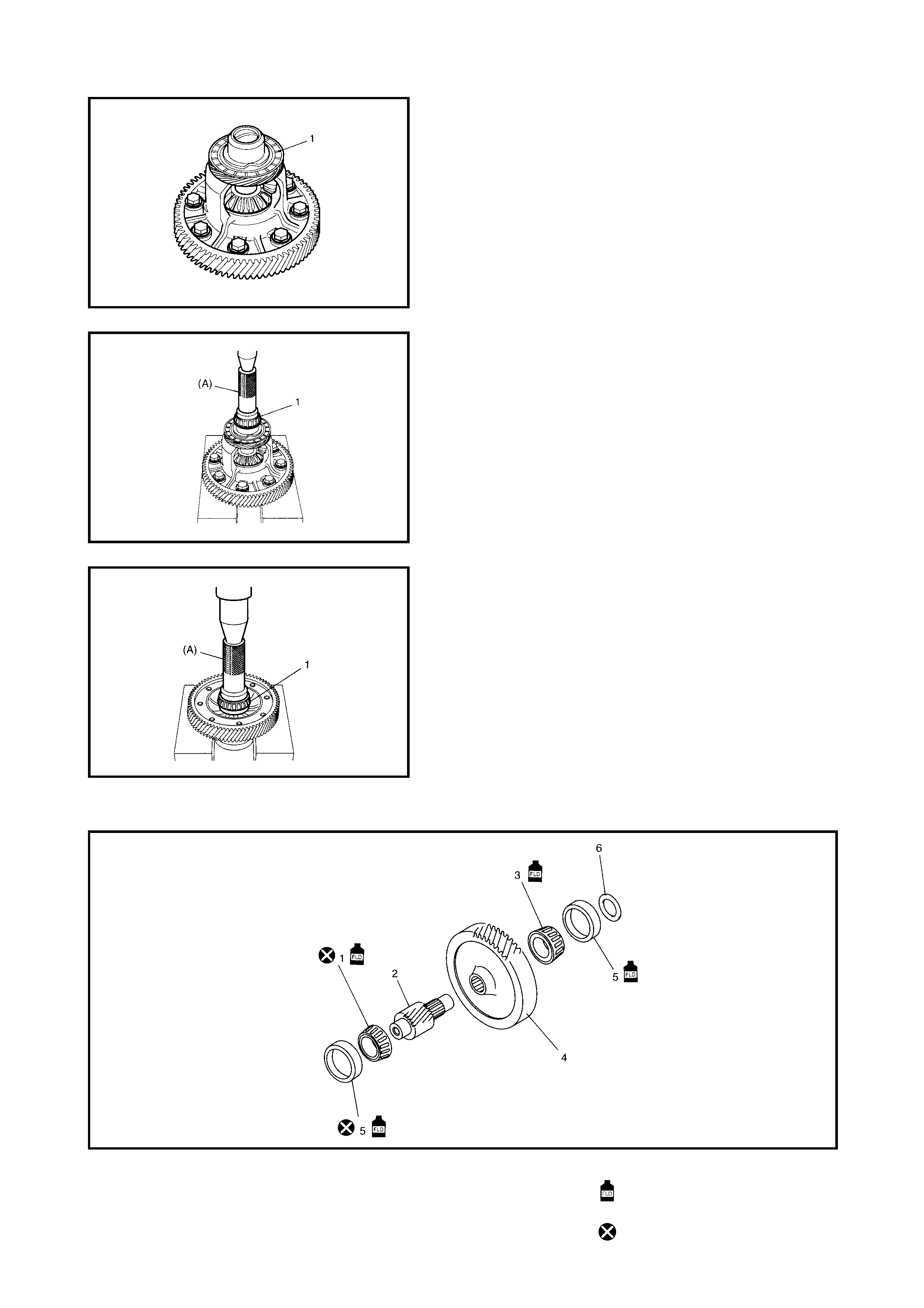
4. After applying A/T fluid to the output shaft speed
sensor (VSS) drive gear (1), install the output shaft
speed sensor drive gear.
5. Install a new differential side RH bearing (1) using
special tool 09913-70123 (A) and a hydraulic press.
NOTE: Replace the differential side RH bearing together
with the bearing cup as a set.
6. Install the new differential side LH bearing (1)using
special tool 09913-70123 (A) and a hydraulic press.
NOTE: Replace the differential side LH bearing together
with the bearing cup as a set.
COUNTERSHAFT
Legend
1. Countershaft RH bearing 4. Reduction driven gear Apply automatic transaxle
fluid.
2. Countershaft 5. Bearing cap
3. Countershaft LH bearing 6. Countershaft bearing shim Do not reuse.
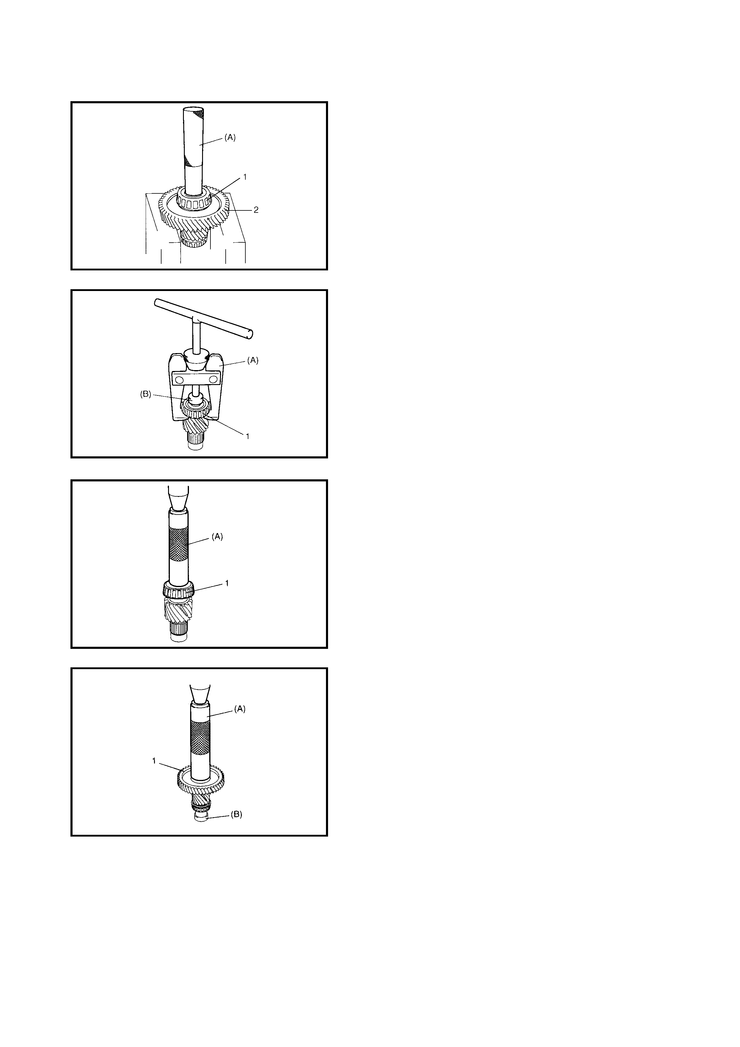
DISASSEMBLY
1. Remove countershaft LH bearing (1) and reduction
driven ge ar (2) as one using spe cial tool 09925-9822 1
(A) and a hydraulic press.
2. Remove th e cou ntershaft RH bear ing (1) using specia l
tools 09913-61510 (A) and (B) 09926-58010.
ASSEMBLY
1. Install a new count er sh aft RH bearing ( 1) usi ng spec ia l
tool 09913-8451 (A) and a hydraulic press.
NOTE: R eplace th e countershaft RH bearing to gether with
the bearing cup as a set.
2. Install the reduction driven gear (1) with special tools
09913-84510 (A), 09925-88210 (B)
and a hydraulic
press.
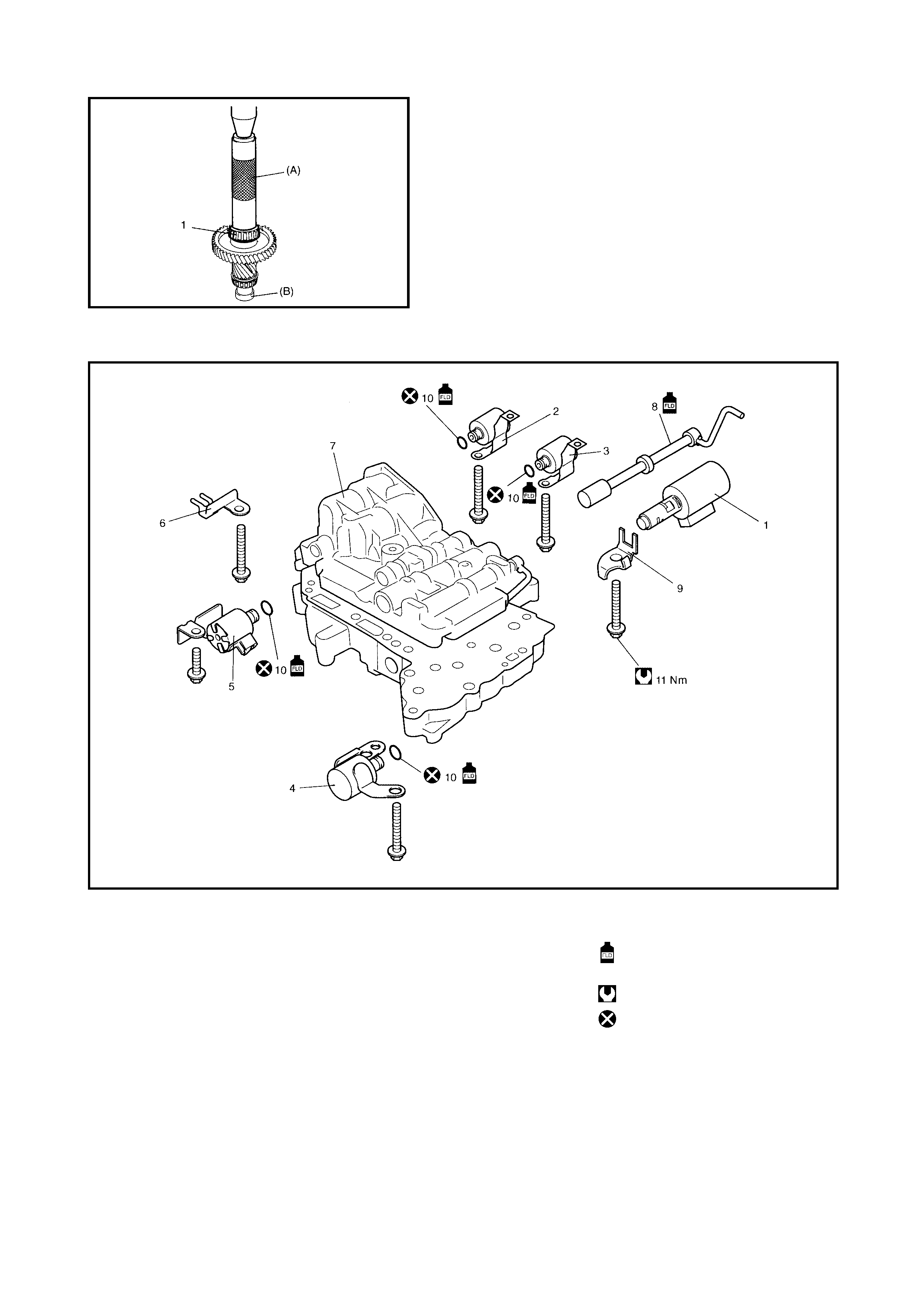
3. Install countershaft LH bearing (1) with special tools
09913-84510 (A), 09925-88210 (B) and hydraulic
press.
VALVE BODY
Legend
CAUTION: When rep lacing the pressure co ntrol soleno id valve, it must be repl aced togeth er with the
valve body assembly as a set. Replacing the pressure control solenoid independently may cause
excessive shift shock.
1. Pressure control solenoid 5. Timing solenoid valve 10. O-ring
valve 6. Temperature sensor clamp Apply automatic transaxle
2. Shift solenoid valve-A (No.1) 7. Valve body assembly fluid.
3. Shift solenoid valve-B (No.2) 8. Manual valve Tightening torque
4. TCC (Lock-up) solenoid valve 9. Solenoid lock plate Do not reuse.
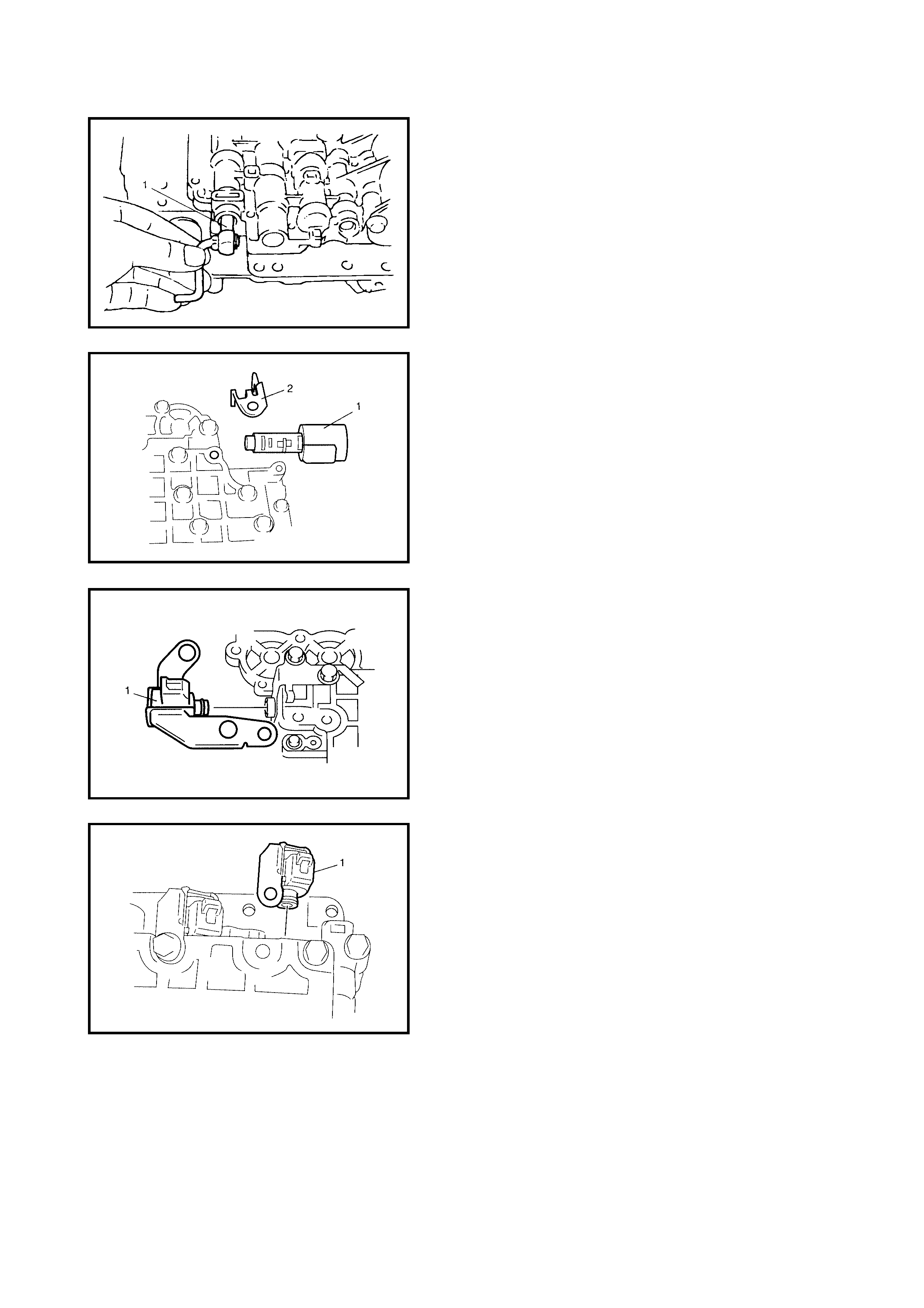
DISASSEMBLY
1. Pull out the manual valve (1).
2. Remove the pressure control solenoid valve (1) and
the solenoid lock plate (2).
3. Remove the TCC (Lock-up) solenoid valve (1).
4. Remove the shift solenoid valve-A (1).
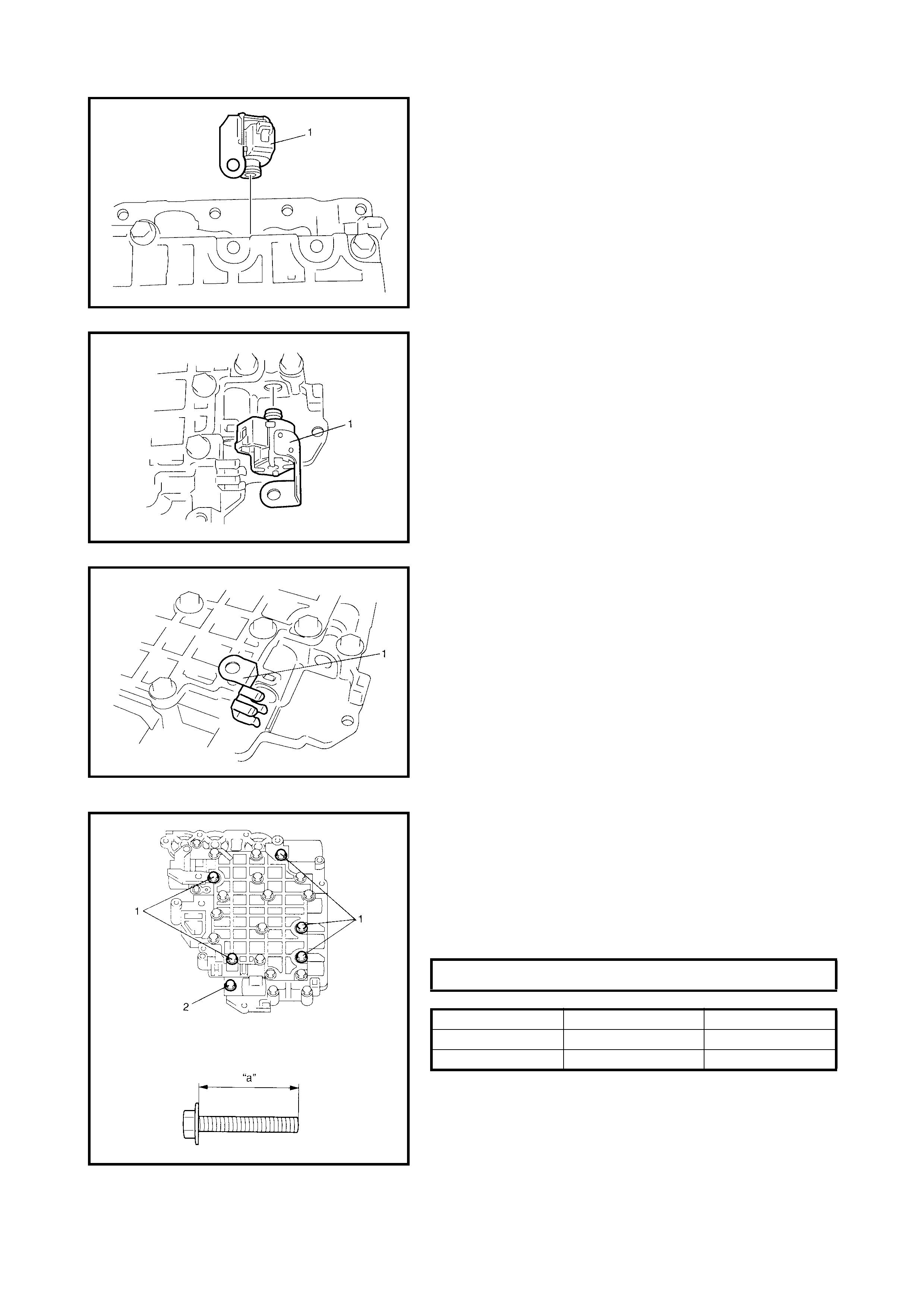
5. Remove shift solenoid valve-B (1).
6. Remove the timing solenoid valve (1).
7. Remove the temperature sensor clamp (1).
ASSEMBLY
• Rev erse the di sass embly pr oced ure for asse mbly, not-
ing the following points.
• Shift solenoid valve-A and -B are identical
• After applying A/T fluid to the new O-rings, fit them to
the solenoid valves, then install the solenoid valves to
the valve body.
• Tighten the solenoid valve bolts to specified torque.
SOLENOID VALVE BOLTS (a) 11 Nm
BOLT LENGTH “A” PIECES
A (1) 49 mm 5
B (2) 20 mm 1
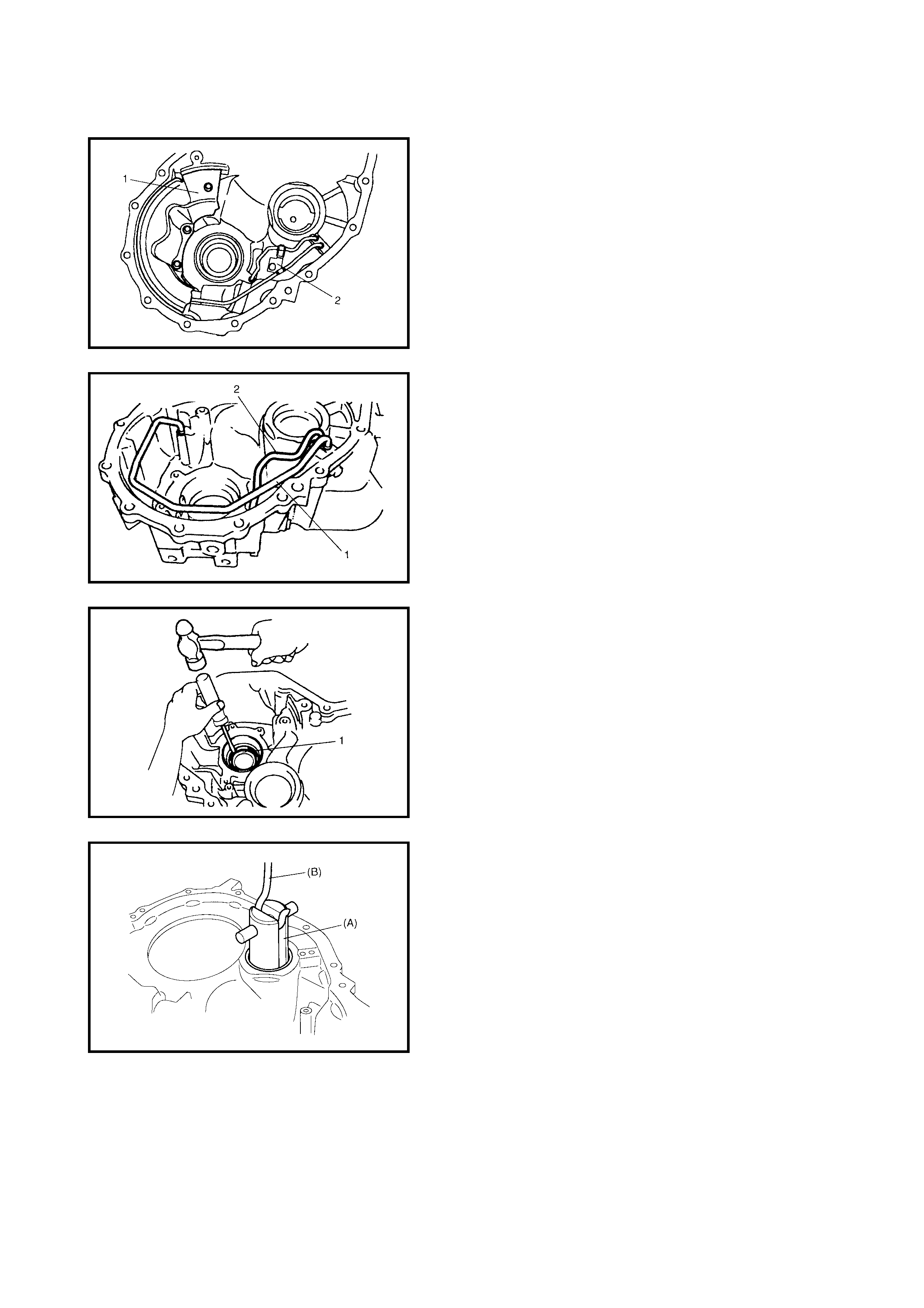
TORQUE CONVERTER HOUSING
Disassembly
1. Remove the fluid reservoir RH plate (1) and the lubri-
cation tube clamp (2).
NOTE: Do not bend the lubrication tube with excessive
force.
2. Remove the lubrication LH tube (1) and RH tube (2).
3. Remove the differential side oil seal (1).
4. Remove the countershaft RH bearing cup using special
tools 09944-96011 (A) and 09942-15511 (B).
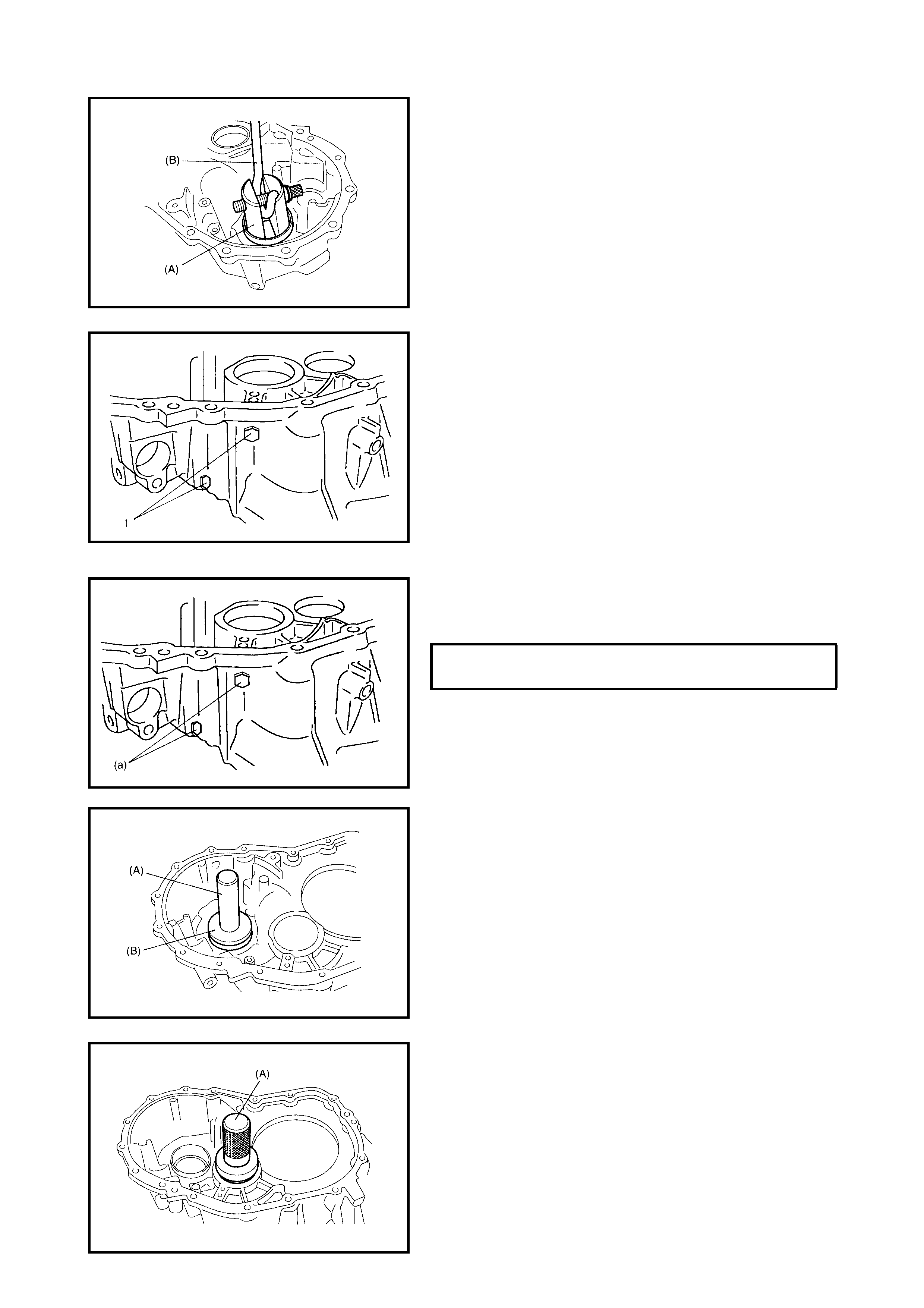
5. Remove the differential side RH bearing cup using
special tools 09944-96011 (A) and 09942-15511 (B).
6. Remove the torque converter case plugs (1).
Assembly
1. After applying A/T fluid to the new O-rings, fit them to
the housing plugs. Finally install the plugs to the torque
converter housing.
2. Using spec ia l tool s 0992 4- 745 10 (A) and 0994 4-68210
(B), assemble the differential side RH bearing cup.
3. Using special tool 09913-75520, install the counter-
shaft RH bearing cup.
TORQUE CONVERTER HOUSING
PLUGS (a) 7.5 Nm
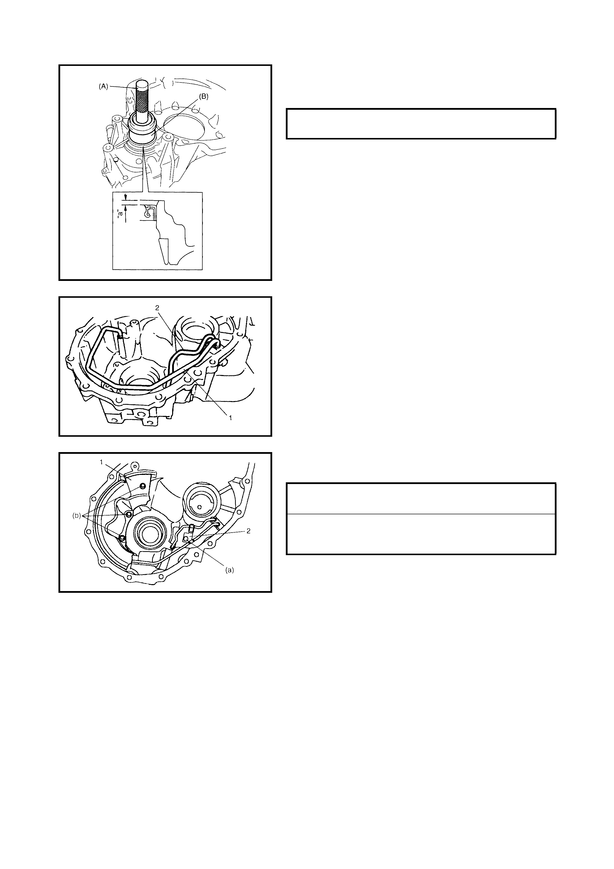
4. Using spec ia l tool s 0992 4- 745 10 (A) and 0994 4-88220
(B), install the new differential side oil seal to the torque
converter housing.
5. Apply grease to the oil seal lip.
Lithium grease
6. Install the lubrication LH tube (1) and RH tube (2).
7. Install the fluid reservoir RH plate (1) and the lubrica-
tion tube clamp (2).
DIFFERENTIAL SIDE OIL SEAL
INSTALLING DEPTH (a) 2.6 - 3.6 mm
LUBRICATION TUBE CLAMP BOLT (a)
TORQUE SPECIFICATION 5.5 Nm
FLUID RESERVOIR RH PLATE BOLTS
(b)
TORQUE SPECIFICATION 5.5 Nm
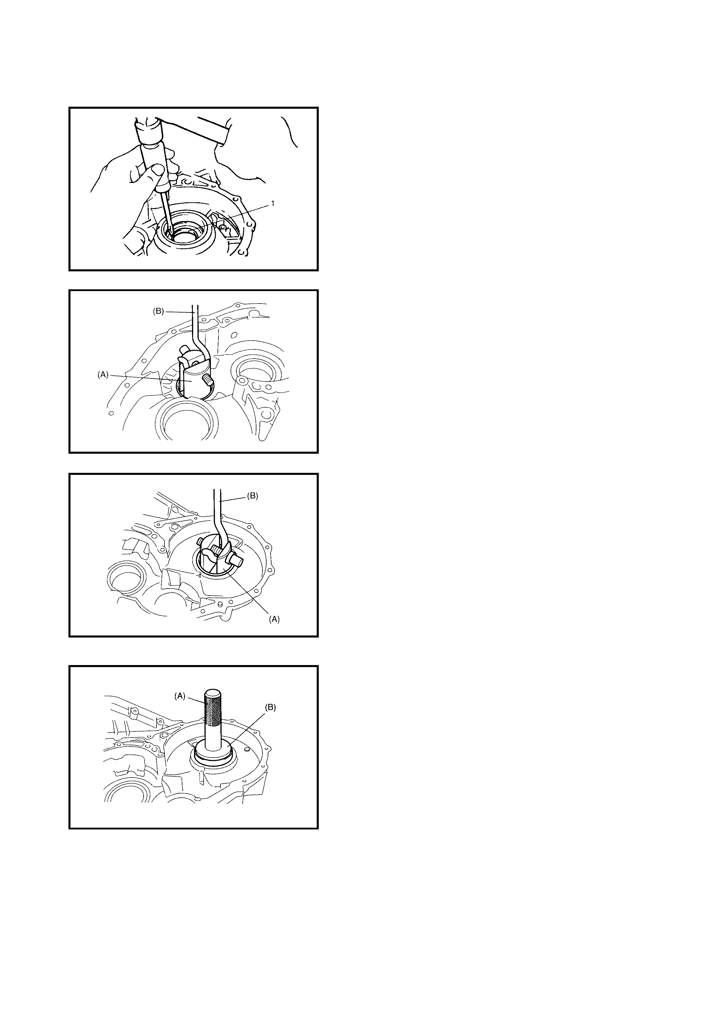
TRANSAXLE CASE
Disassembly
1. Remove the differential side oil seal (1).
2. Remove the countershaft LH bearing cup and shim
with special tools 09944-96011 (A) and 09942-15511
(B).
3. Remove the differential side L H bearing cup and shim
with special tools 09944-96011 (A) and 09942-15511
(B).
Assembly
1. Using spec ia l tool s 0992 4- 745 10 (A) and 0994 4-68210
(B), assemble the shim and differential side LH bearing
cup.
NOTE: Use a shim with same thickness as the one
removed.
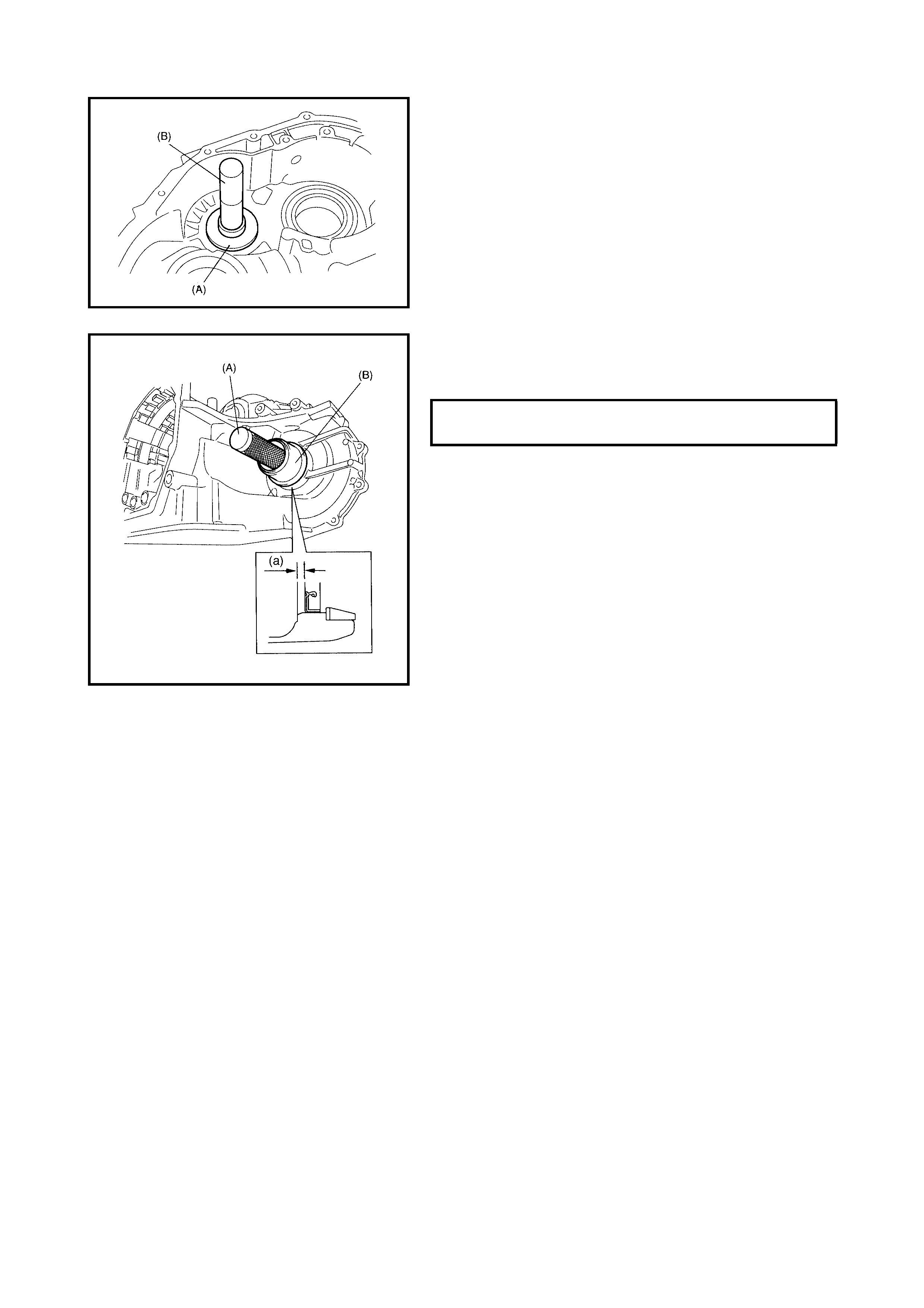
2. Using special tools 09924-84510-002 (A) and 09913-
75821 (B), assemble the shim and countershaft LH
bearing cup .
NOTE: Use shim with the same thickness as the one
removed.
3. Install a new differential side oil seal to the transaxle
case using special tools 09924-74510 (A) and 09944-
88220 (B).
4. Apply grease to the oil seal lip.
Lithium grease
DIFFERENTIAL SIDE OIL SEAL
INSTALLING DEPTH (a) 3.8 - 4.8 mm
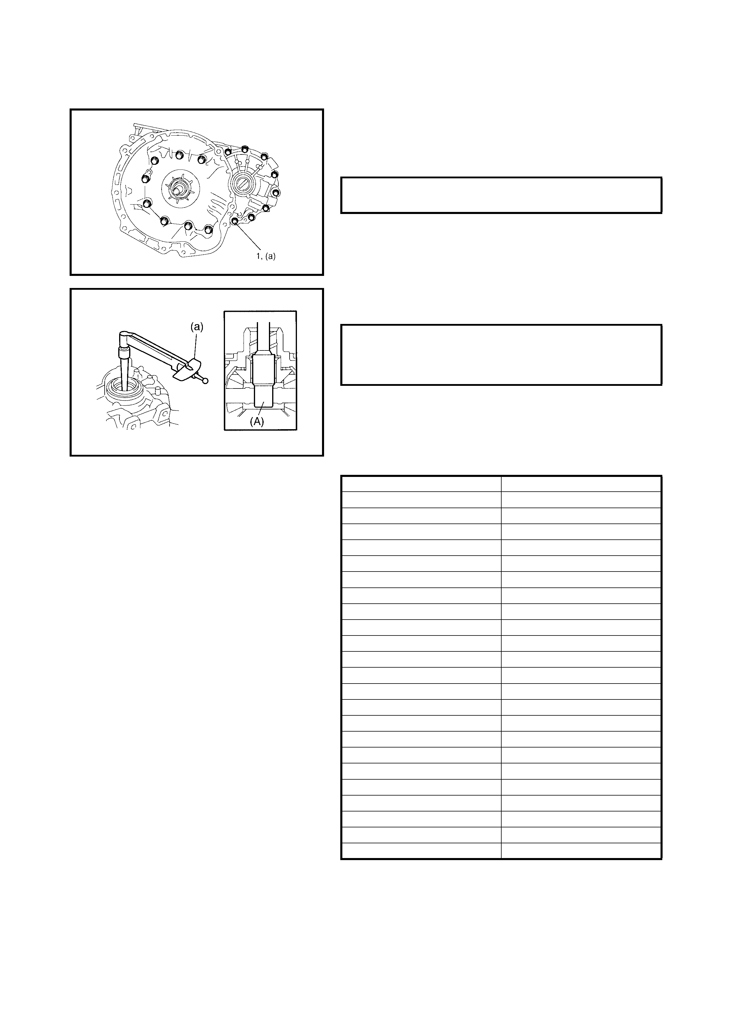
ADJUSTMENT BEFORE UNIT ASSEMBLY
Differential Side Bearing Preload
1. After applying A/T fluid to the differential assembly, fit it
to the transaxle case.
2. Install the torque converter housing to the transaxle
case, then tighten bolts (1) to the specified torque.
3. Measure the bearing preload (a) using special tool
09928-060 50 (A) .
4. If the bearing preload is out of specification, select a
shim with a suitable thickness from the list below and
replace it. Adjust the differential side bearing preload to
be within specification.
Available shim thickness
NOTE: Record the measured v alue (a), as i t is required to
adjust the counter shaft bearing preload.
5. Remove the differential assembly.
TORQUE CONVERTER HOUSING
BOLTS (a) 33 Nm
DIFFERENTIAL SIDE BEARING PRE-
LOAD (STARTING TORQUE) (a)
NEW BEARING
RE-USED BEARING 0.8 -1.4 Nm
0.4 - 0.7 Nm
THICKNESS IDENTIFICATION MARK
1.80 mm A
1.85 mm B
1.90 mm C
1.95 mm D
2.00 mm E
2.05 mm F
2.08 mm G
2.11 mm H
2.14 mm J
2.17 mm K
2.20 mm L
2.23 mm M
2.26 mm N
2.29 mm P
2.32 mm Q
2.35 mm R
2.40 mm S
2.45 mm T
2.50 mm U
2.55 mm V
2.60 mm W
2.65 mm X
2.70 mm Y

Counter Shaft Bearing Preload
1. Apply A/T fluid to the countershaft assembly (1) and
the differential assembly (2) before installation.
2. Install torque converter housing to the transaxle case,
then tighten bolts to specified torque.
3. Measure the bearing preload (b) by using special tool
09928-060 50 (A) .
Counter shaft bearing preload (c) = (b) – Differential side
bearing preload (a) as previously noted.
4. If the bearing preload is out of specification, select a
shim with a suitable thickness from the list below and
replace it. Adjust the countershaft bearing preload to
be within specification.
Available shim thickness
5. Remove the differential assembly and counter shaft
assembly.
TORQUE CONVERTER HOUSING
BOLTS
TORQUE SPECIFICATION 30 Nm
COUNTER SHAFT BEARING PRELOAD
(STARTING TORQUE) (c)
NEW BEARING
RE-USED BEARING 0.33 - 0.76 Nm
0.17 - 0.38 Nm
THICKNESS IDENTIFICATION MARK
1.70 mm 1
1.75 mm 2
1.80 mm 3
1.85 mm 4
1.90 mm 5
1.93 mm 6
1.96 mm 7
1.99 mm A
2.02 mm B
2.05 mm C
2.08 mm D
2.11 mm E
2.14 mm F
2.17 mm G
2.20 mm H
2.25 mm K
2.30 mm L
2.35 mm M
2.40 mm N
2.45 mm P
2.50 mm Q
2.55 mm R
2.60 mm S
2.65 mm U
2.70 mm W
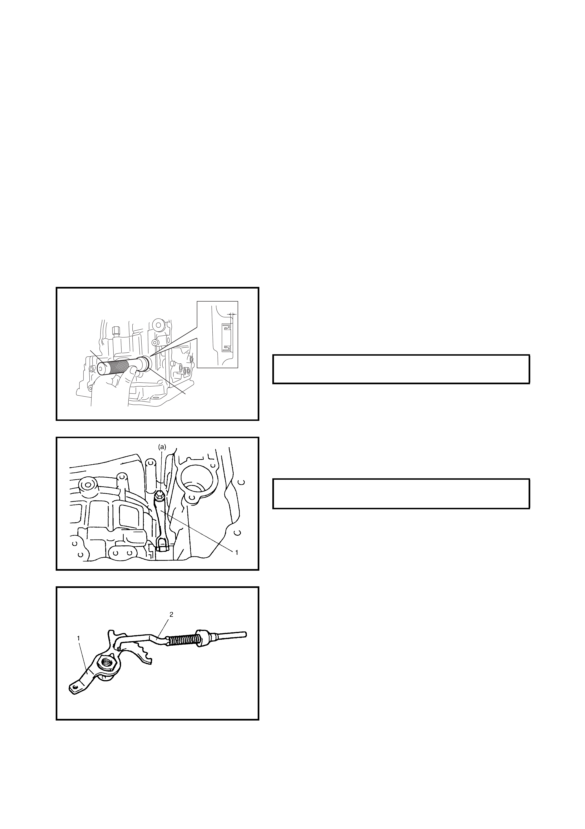
4.6 UN IT ASSEMBLY
CAUTION:
• The automatic transaxle consists of precision parts. Even a flaw in a small part may cause oil leak-
age or a decrease in function, check each part carefully before installation.
• Clean all parts with compressed air. Never use cloths or rags.
• Before assembling new clutch or brake discs, soak them in A/T fluid for at least 2 hours.
• Always use new gaskets and O-rings.
• Lubricate O-rings with A/T flu id.
• Apply A/T fluid to sliding or rotating surfaces of parts before assembly.
• Lithium grease to retain parts in place.
• Be sure to install thrust bearings and races in the correct direction and position.
• Make sure that snap ring ends are not aligned with the cutouts and are installed in their groove
correctly.
• Do not use adhesive cements on gaskets or similar p arts.
• Be sure to torque each bolt and nut to specification.
1. Install a new m anu al s hi ft shaft oil seal to t he tr an sa xl e
case.
Use special tool 09925-98210 (A) and a hammer to
install, then apply grease to its lip.
“A”: Lithium grease
2. Install the manual detent spring (1) to the transaxle
case and tighten the manual detent spring bolt to
specified torque.
3. Install the parking lock pawl rod (2) to the manual valve
lever (1).
MANUAL SHIFT SHAFT OIL SEAL
INSTALLING DEPTH (a) 0.75 - 1.25 mm
“a”
(A)
“A”
MANUAL DETENT SPRING BOLT (a)
TORQUE SPECIFICATION 10 Nm
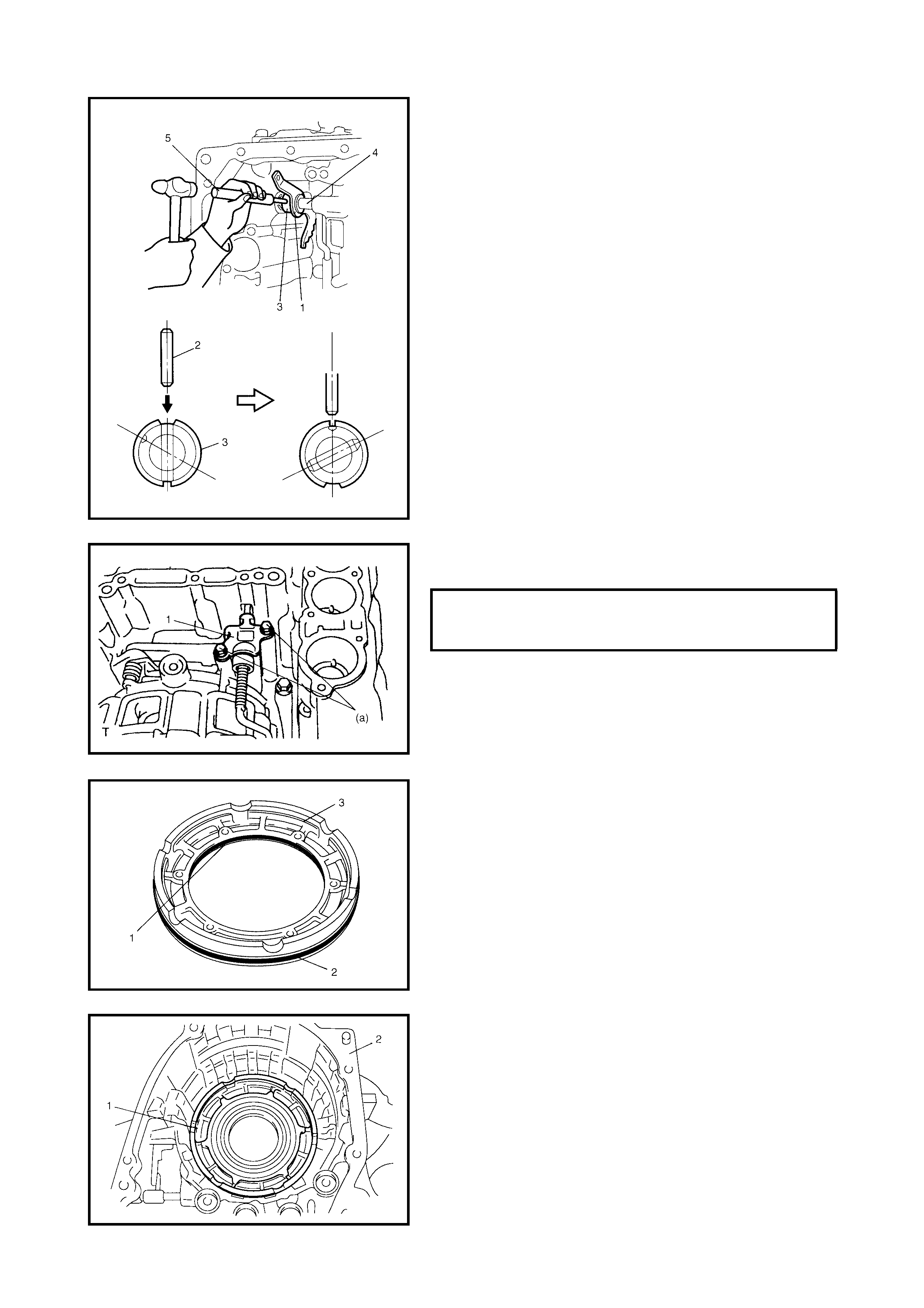
4. After applying A/T fluid to the new manual valve lever
(1), install new manual shift shaft (4), new spacer (3)
and manual valve lever to the transaxle case.
5. After installing the manual valve lever pin (2) using
spring pin remover with (3 mm diameter) (5) and a
hammer , turn spacer to set the position as shown in the
figure. Then stake the spacer with a punch.
6. Install the parking lock pawl bracket (1) to the transaxle
case.
7. After applying A/T fluid to the new O-rings, inner O-ring
(1) and outer O-ring (2), install them to the 1st and
reverse brake piston (3).
8. Install the 1st and reverse brake piston (1) to the
transaxle case (2).
NOTE: Be careful not to damage the O-ring when installing
the 1st and reverse brake piston.
PARKING LOCK PAWL BRACKET
BOLTS (a)
TORQUE SPECIFICATION 7.5 Nm
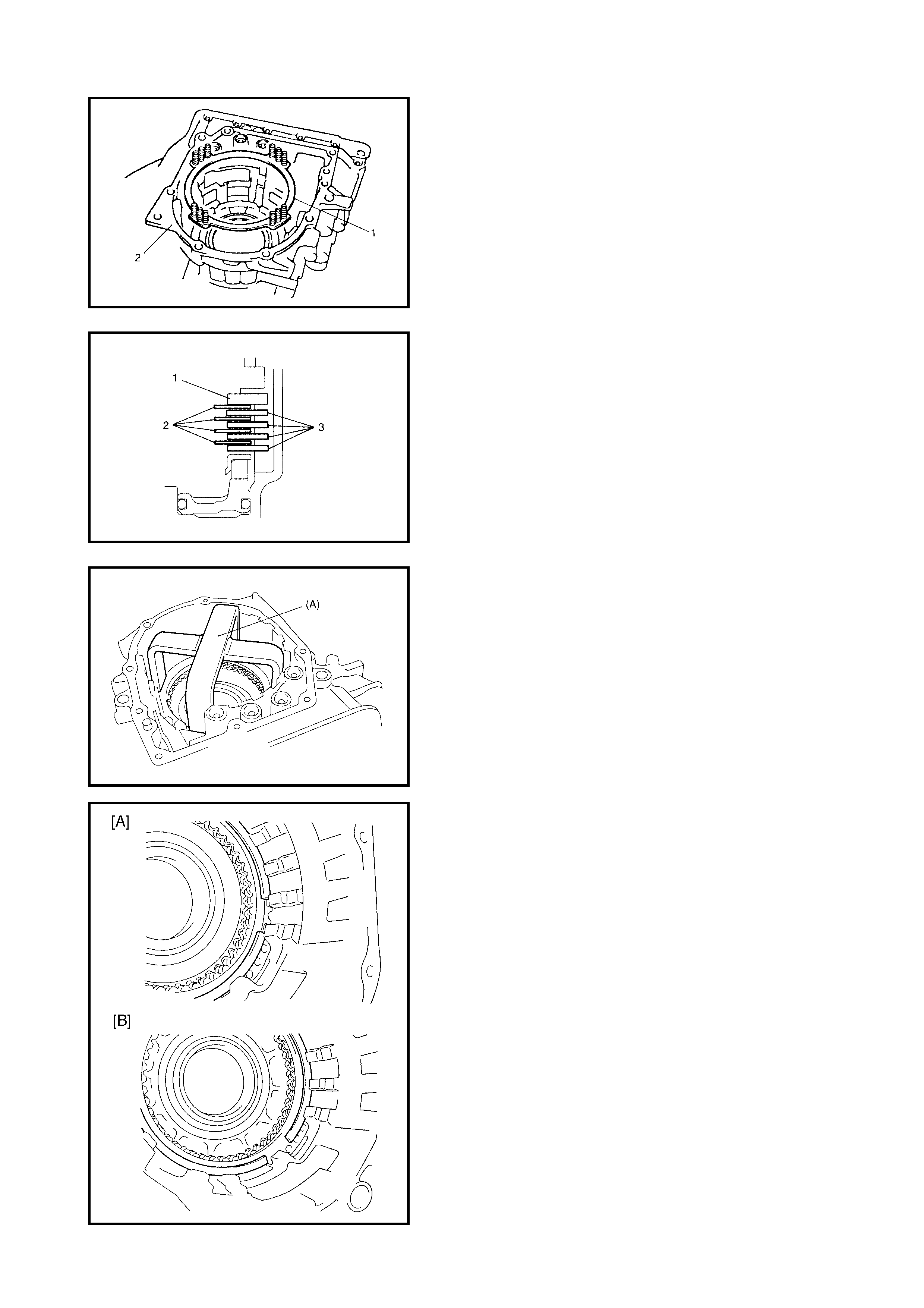
9. Install the 1st and reverse brake return spring subas-
sembly (1) to the transaxle case (2).
10. Apply A/T fluid to the 1st and reverse brake discs (2),
separator plates (3) and the retaining plate (1), then
install them to the transaxle case.
CAUTION:
Do no t damage th e 1st and revers e brake
return spring subassembly discs, plates and piston
by pressing in the 1st and reverse brake return
spring subassembly more than 0.8 mm past its orig-
inal installation position.
11. Compress the 1st and reverse brake return spring
using special tool 09926-97620 (A) and a hydraulic
press, then attach snap ring.
12. Install the 1st and reverse brake plate snap ring so that
its ends are positioned correctly.
[A] - Correct
[B] - Incorrect
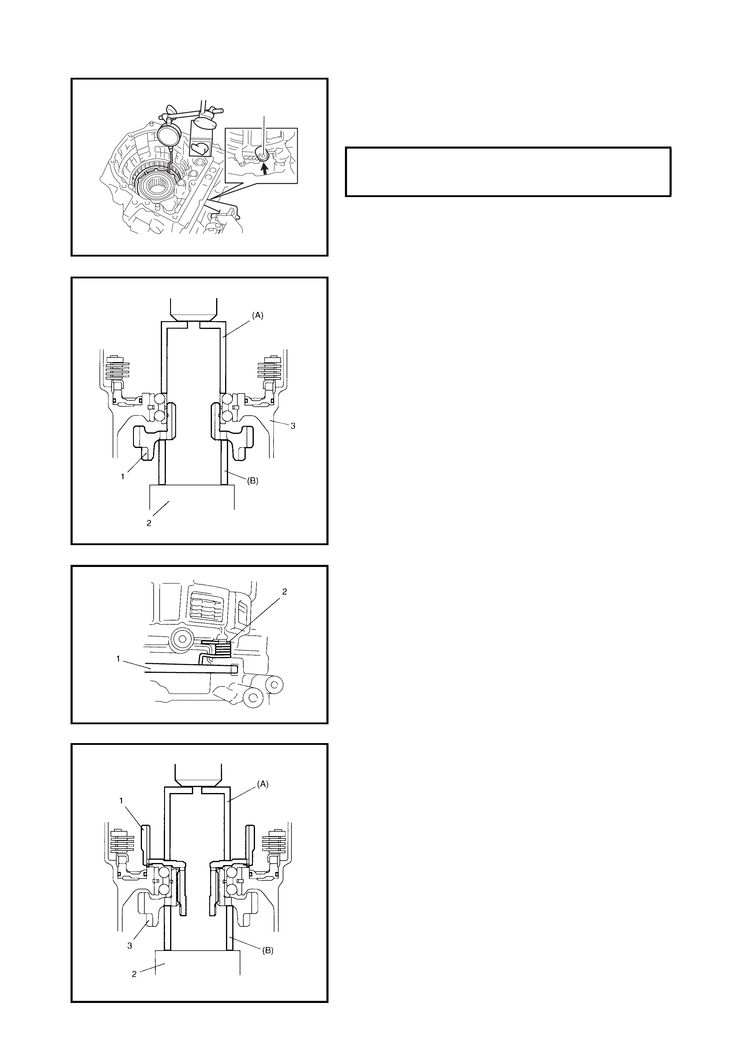
13. Using sp eci al too ls 09 900-2 0607 ( A), 09 900 -2070 1 ( B)
and 09952-06020 (C), measure the 1st and reverse
brake piston stroke when compressed air (400 – 800
kPa) is blown through the oil hole (1).
CAUTION:
• Do not use the transaxle case as groundwork to
press fit the reduction drive gear, use a stand that
can lift the transaxle case slightly.
• Do not place a load of more than 20 kN with the
hydraulic press or the reduction drive gear bearing
may be damaged.
14. Install the reduction drive gear (1) to the transaxle case
(3) using special tools 09951-18210 (A) and 09944-
78210 (B) and a hydraulic press.
NOTE: When replacing reduction drive gear, replace it
together with reduction driven gear as a set.
15. Install the parking lock pawl (1) and spring (2). Apply A/
T fluid to the park ing lock pawl shaft, then insert it into
the transax le case.
CAUTION:
• Do not reuse the planetary ring gear subassembly
or it may cause damage to the planetary gear unit
and/or the reduction gears.
• Do not use the transaxle case as groundwork to
press fit the planetary ring gear subassembly, use
a stand that can lift the transaxle case slightly.
• Do not place a load of more than 20 kN with the
hydraulic press or it may damage the reduction
drive gear bearing.
16. Install a new planetary ring gear subassembly (1) to
the reduction drive gear (3) using special tools 09951-
18210 (A), 09944-78210 (B) and a hydraulic press.
1ST AND REVERSE BRAKE PISTON
STROKE STANDARD 0.791 - 1.489 mm
1
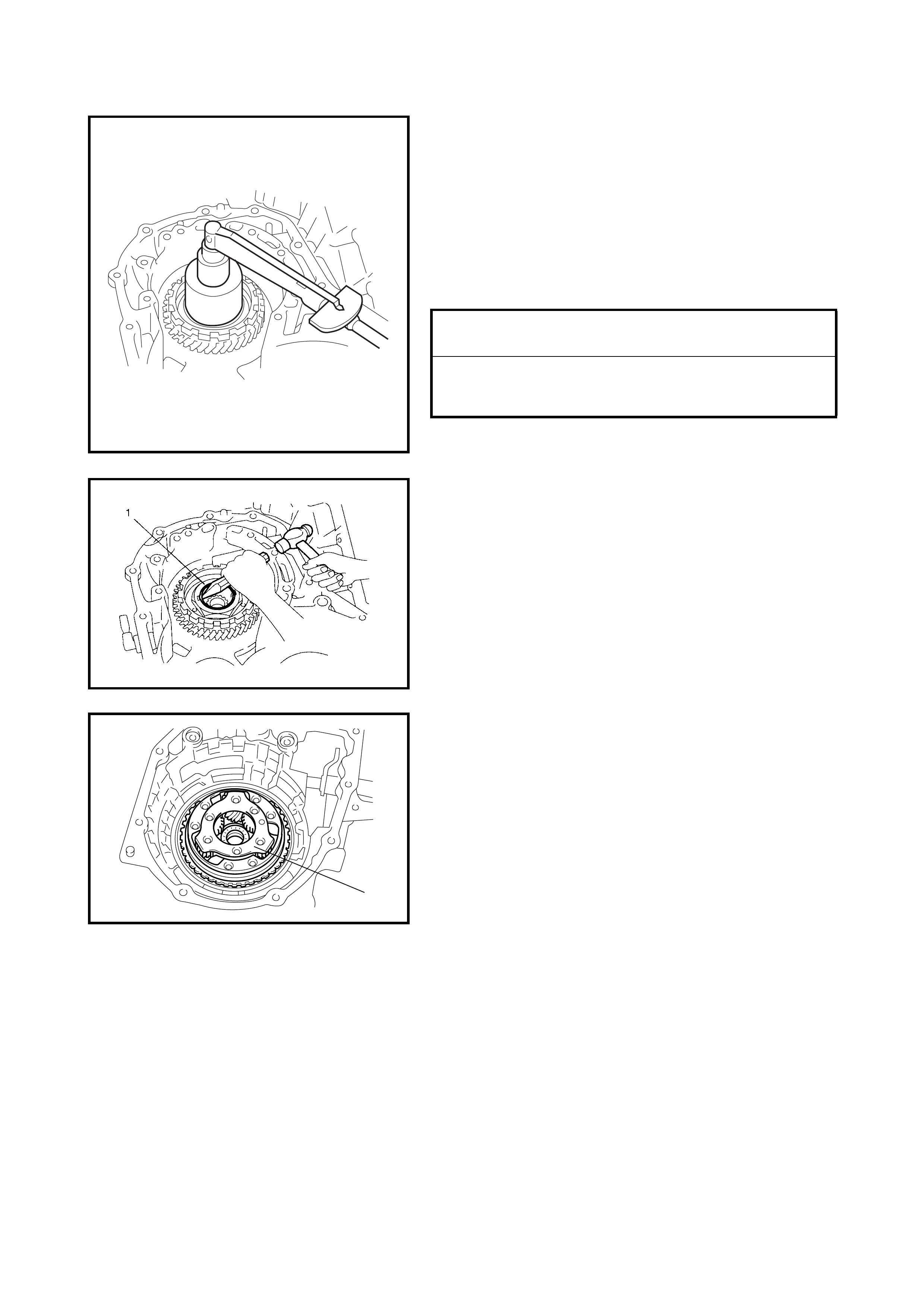
CAUTION:
• Do not exceed specifications when tightening the
reduction drive gear nut or nut may break.
• Carry out this procedure on a rubber mat to avoid
damaging the transaxle case.
17. Tighten the new reduction drive gear nut to the
planetary ring gear subassembly gradually until the
reduction drive gear bearing preload is within
specification.
18. Stake the reduction drive gear nut (1).
19. Apply A/T fluid to the planetary gear assembly (1), then
fit it to the planetary ring gear assembly.
REFERENCE
TORQUE SPECIFICATION 100 Nm
REDUCTION DRIVE GEAR BEARING
PRELOAD (STARTING TORQUE)
STANDARD 0.05 - 0.35 Nm
1
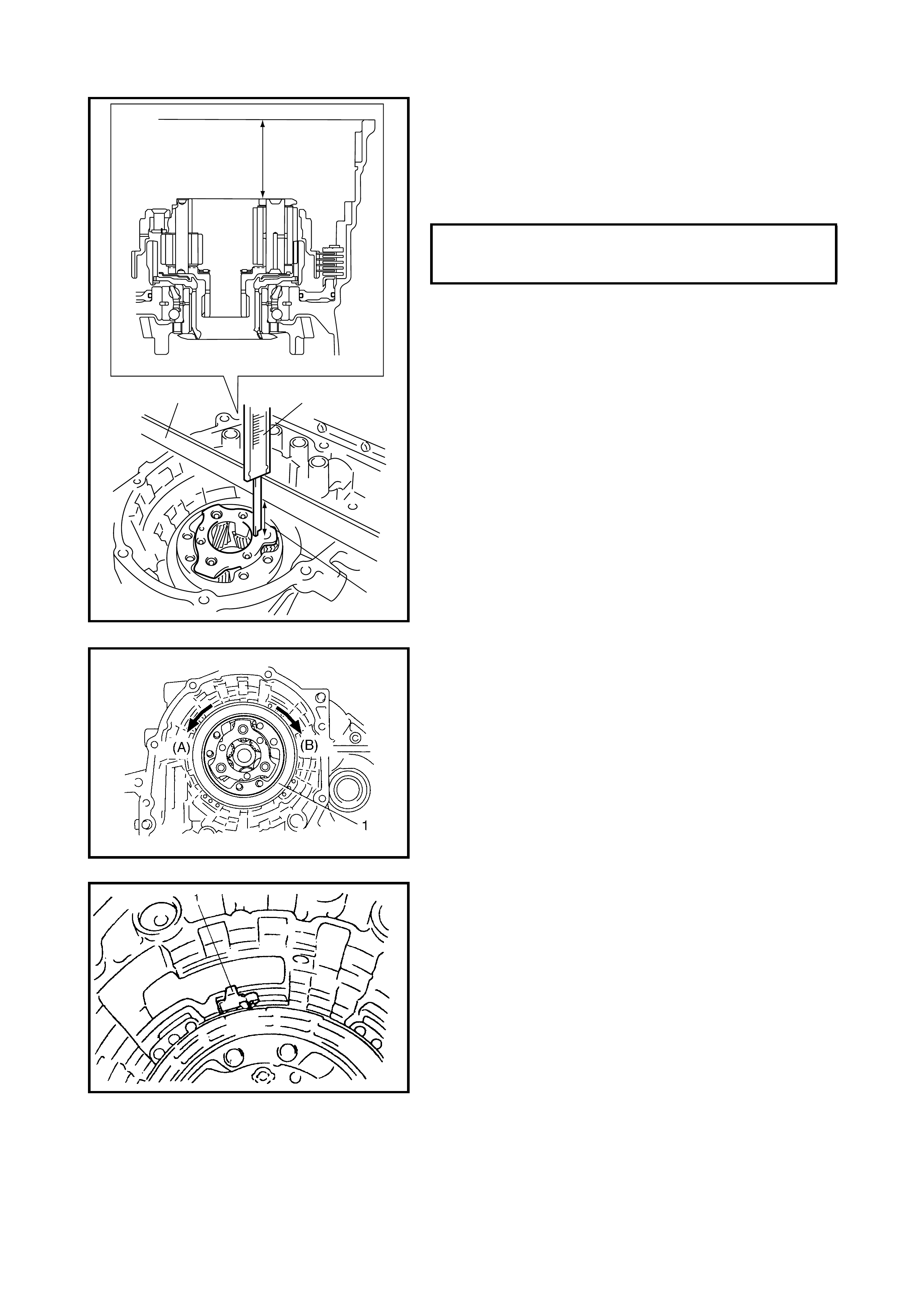
20. Check for correct installation of the planetary gear
assembly as follows.
Measure the distance (a) using a micrometer caliper
(1) and a str aig hte dge (2 ). If th e m eas ured va lu e i s o ut
of specification, remove the planetary gear assembly
and reinstall it correctly.
21. Apply A/T fluid to the one-way clutch No.2 assembly
(1), then install it to the planetary gear assembly.
Ensure that the planetary carrier rotates in a counter-
clockwise direction (A) only, not in a clockwise direction
(B).
22. Install the one-way clutch outer race retainer (1).
DISTANCE BETWEEN PLANETARY
GEAR ASSEMBLY AND MATING SUR-
FACE OF TRANSAXLE CASE (a) MORE THAN
49.9 mm
“a”
“a”
21
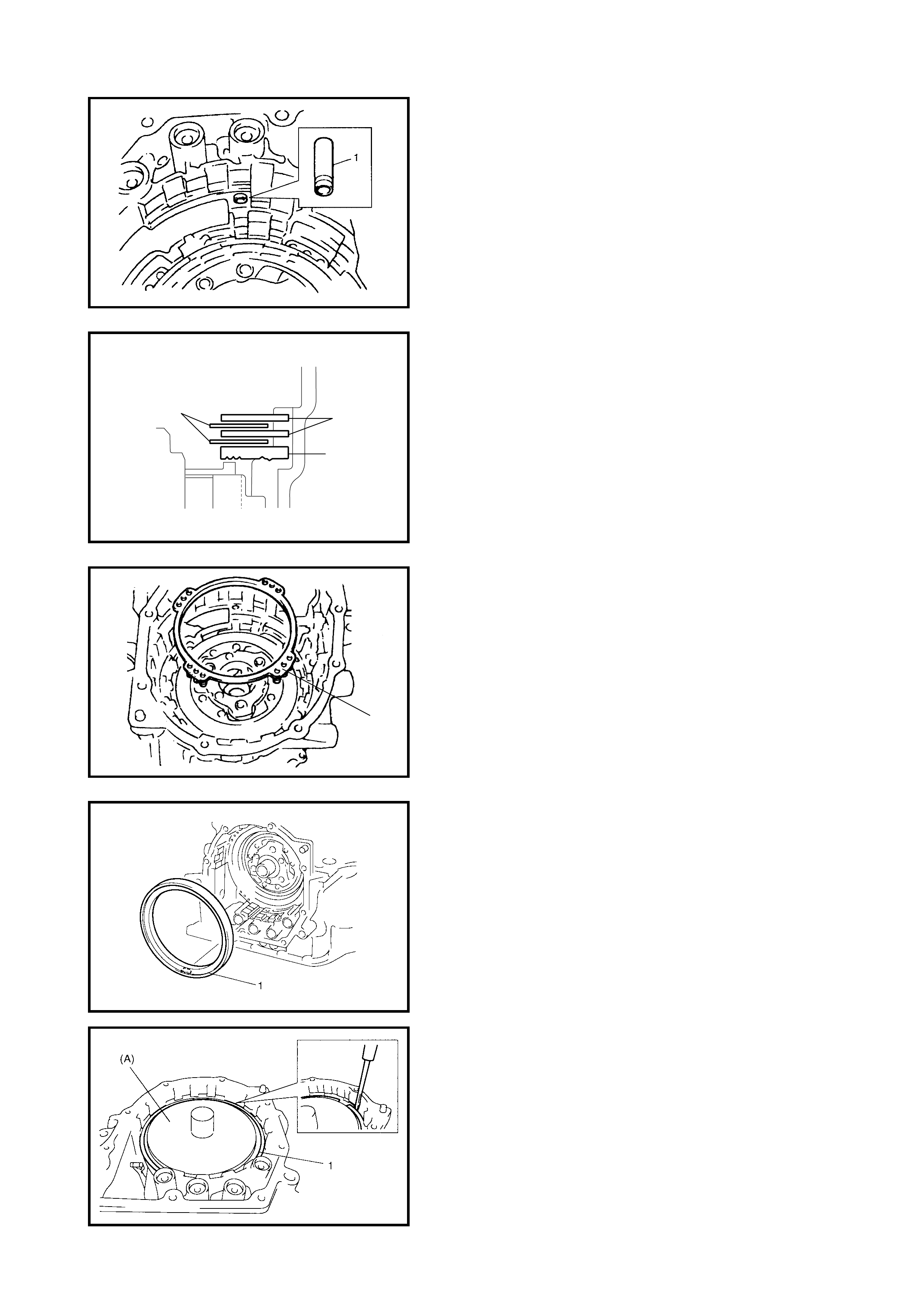
23. Apply A/ T fluid to the new brak e drum gask et (1), then
install it to the transaxle case.
24. Apply A/T fluid to the 2nd brake retaining plate (1),
discs (2) and separator plates (3), then install them to
the transax le case.
25. Install the 2nd brake return spring subassembly (1) to
the transax le case.
26. Apply A/T fluid to the 2nd brake piston assembly (1),
and align the projection of the 2nd brake piston
assembl y with the groove on the transaxle c ase, then
fit together.
CAUTION: Do not damage the 2nd brake piston assem-
bly, return spring subassembly, plates and discs by
pressing in the 2nd brake a ssembly more than 0.4 mm
past its original installation position
.
27. Install 2nd brake piston snap ring (1) by using special
tool 09926-96050 (A) and hydraulic press.
23
1
1
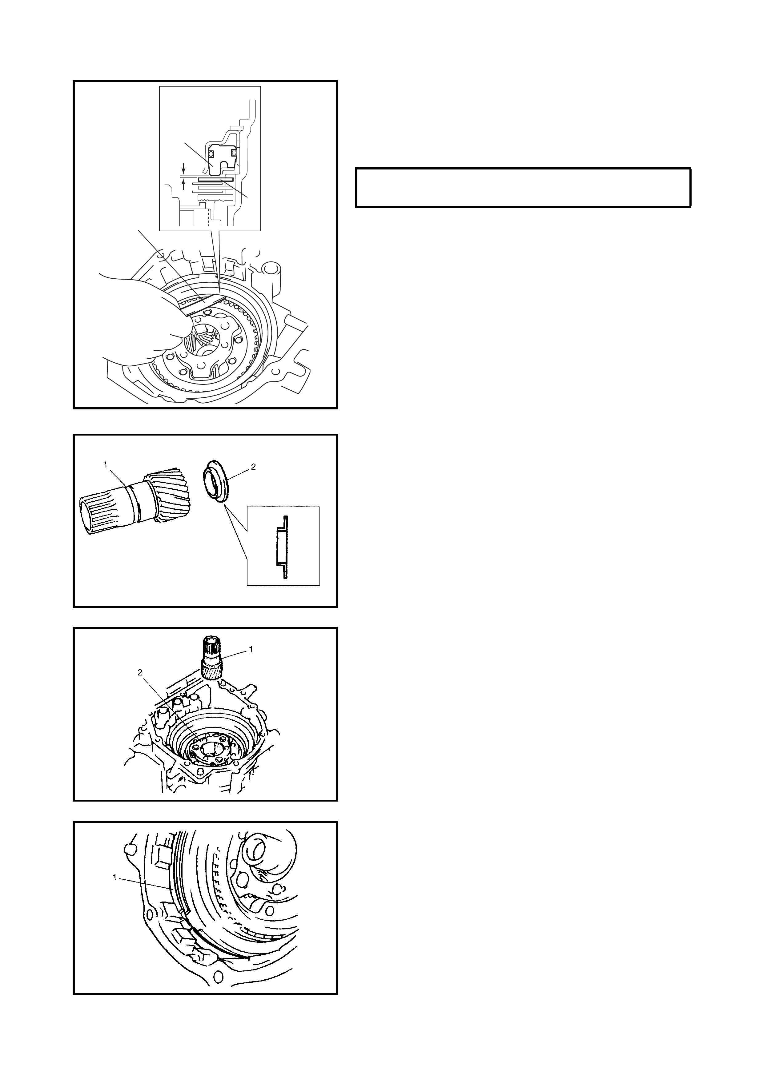
28. Check the 2nd brake piston stroke by measuring the
clearance between the 2nd brake separator plate (1)
and the piston (2) with a feeler gauge (3).
If the clearance (piston stroke) is out of specification
replace the clutch discs and plates with new ones.
CAUTION: When component parts of the 2nd brake
(namely brake disc, retaining plate and/or separator
plate) have been re-pla ced, all lear ned contents, which
have been stored in TCM memory by executing learn-
ing control, should be initialised, refer to
3.12 TRANSMISSION CONTROL MODULE - LEARNING
CONTROL INITIALISATION in this Section.
Neglectin g this init ialis atio n may ca u se ex ces sive shift
shock.
29. After applying A/T fluid to the front sun gear thrust
bearing race (2), install it to the front planetary sun
gear (1).
30. Apply A/T fluid to the front planetary sun gear (1) and
install it to the planetary gear assembly (2).
CAUTION: Be sure to install the O/D and 2nd coast
brake retaining plate snap ring correctly in the groove
in the transaxle case.
31. Install the O/D and 2nd coast brake retaining plate
snap ring (1).
2ND BRAKE PISTON STROKE
STANDARD 0.40 - 1.25 mm
3
2
1
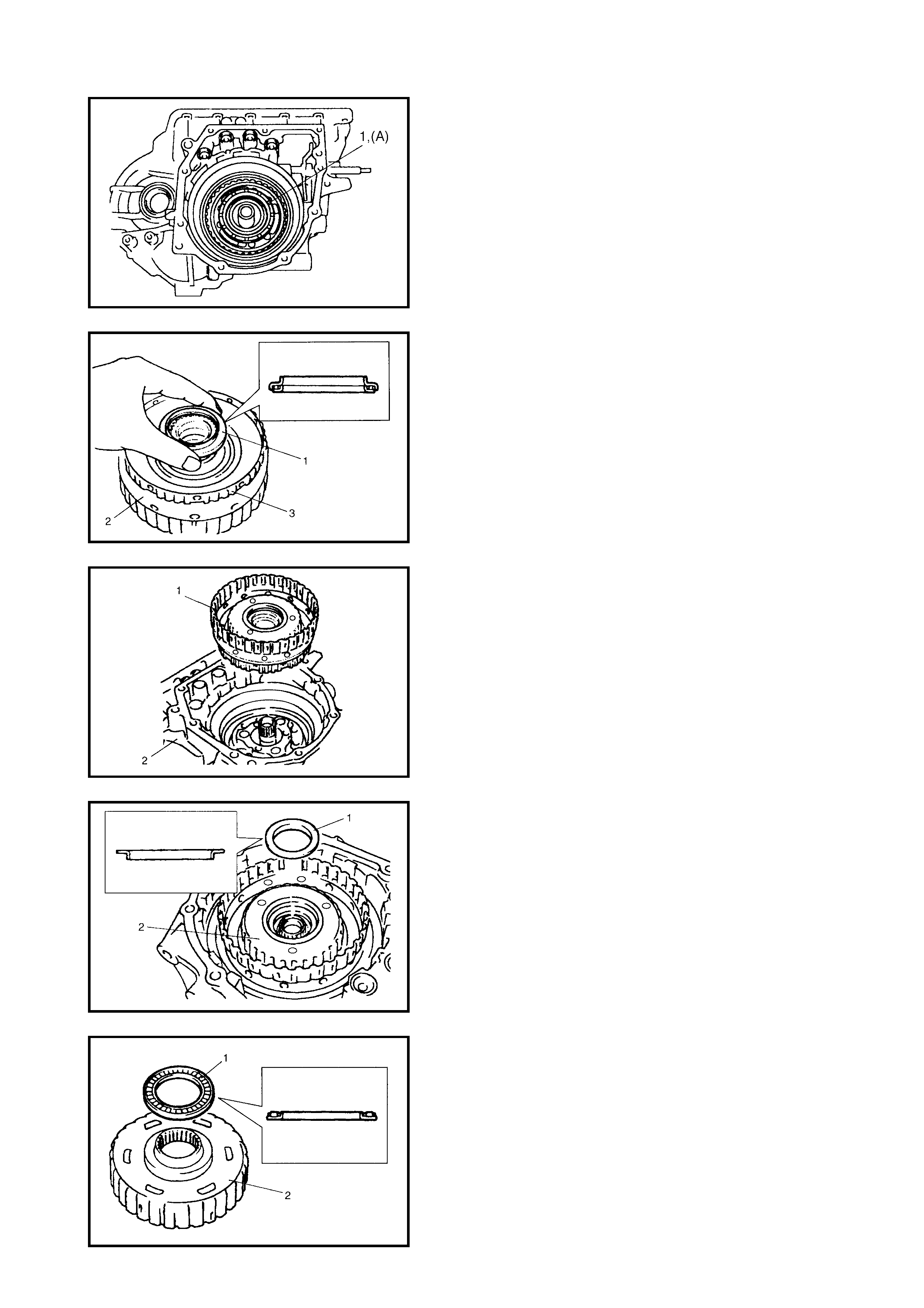
32. After applying grease to the slide contact face of the
planetary carrier thrust washer (1), install it to the
planetary gear assembly.
(A): Lithium grease
33. Apply A/T fluid to the one-way clutch No.1 assembly
(3) and install the one -way clutc h No.1 ass embly (3) to
the rear planetary sun gear subassembly (2).
34. Apply A/ T fluid to the plan etary gear th rust bearing (1) ,
then install it to the one-way clutch No.1 assembly (3).
35. After applying A/T fluid to the rear planetary sun gear
subassembly and the one-way clutch No.1 assembly
(1), install them in the transaxle case (2).
36. After applying A/T fluid to the rear sun gear thrust
bearing race (1), install it to the rear planetary sun gear
(2).
37. After applying A/T fluid to the rear sun gear thrust
bearing (1), install it to the forward clutch hub (2).
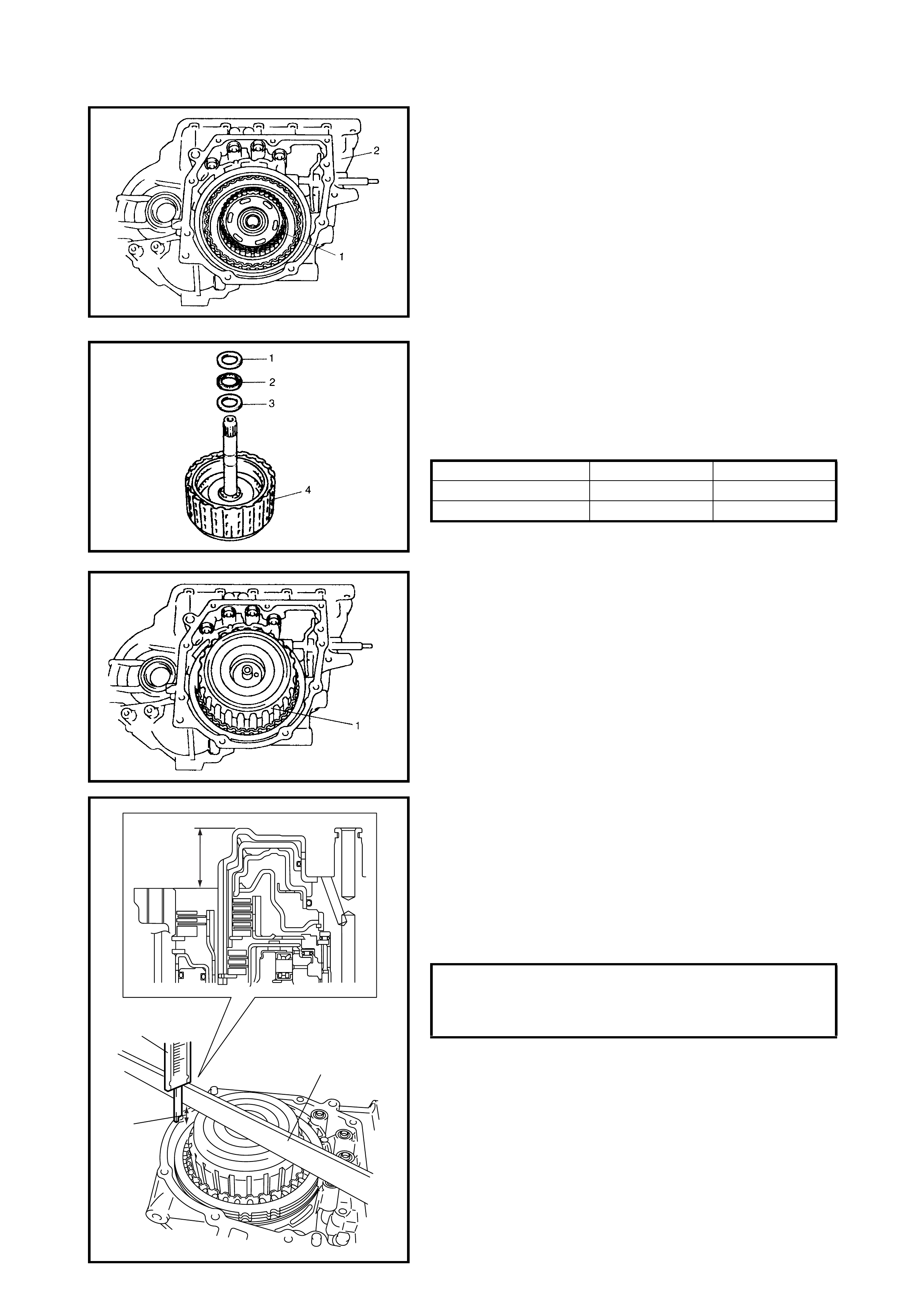
38. After applying A/T fluid to the forward clutch hub (1),
install it in the transaxle case (2).
39. After applying A/T fluid to the interme diate shaft thrust
bearing rear race (3), thrust bearing (2) and front race
(1), install them to the forward and reverse clutch
assembly (4).
Bearin g race dimension
40. Apply A/T fluid to the forward and reverse clutch
assembly (1).
Install the forward and reverse clutch assembly by
rotating clockwise and counter clockwise frequently to
fit the clutch discs to the mating hubs.
NOTE: Before installation, align the teeth of the forward
and reverse clutch discs to ease installation.
41. Check for correct installation of the forward and
reverse clutch assembly as follows.
Measure distance “a” using a micrometer caliper (1)
and straightedge (2). If the measurement is out of
specification, remove the forward and reverse clutch
assembly, forward clutch hub, rear planetary sun gear
subassembly and one-way clutch No.1 assembly and
reinstall them cor rectl y.
FRONT RACE REAR RACE
OUTSIDE DIAMETER 30.6 mm 28.2 mm
THICKNESS 2.0 mm 2.0 mm
DISTANCE BETWEEN FORWARD AND
REVERSE CLUTCH ASSEMBLY AND
MATING SURFACE OF TRANSAXLE
CASE (a) LESS THAN
29.4 mm
“a”
“a”
1
2
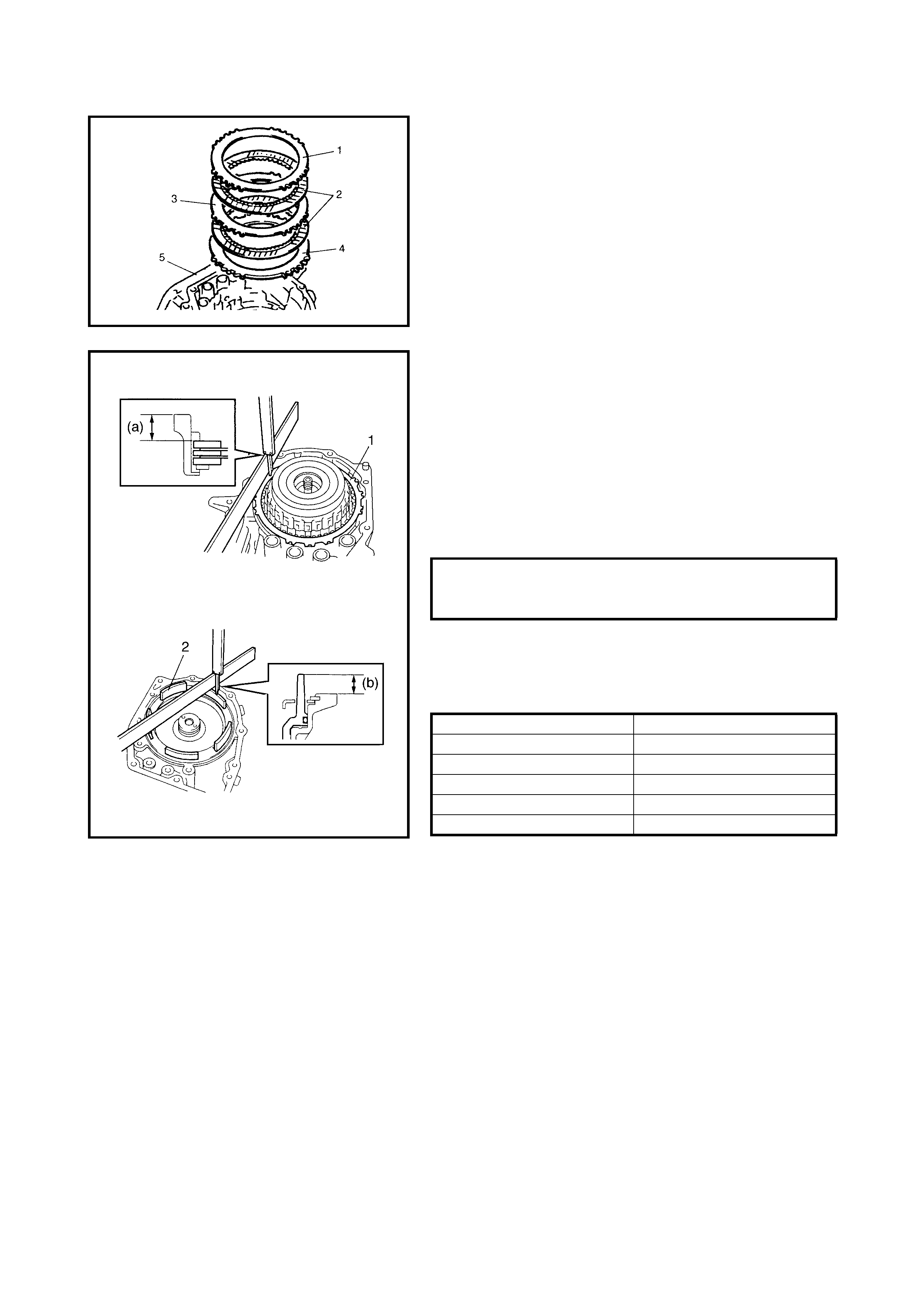
42. After applying A/T fluid to the O/D and 2nd coast brake
retaining plate (4), separator plate (3), discs (2) and
rear plate (1), install them to the transaxle case (5).
43. Measure the O/D and 2nd coast brake piston stroke.
• Measure dimension (a) from the end face of the tran-
saxle case to the O/D and 2nd coast brake rear plate
(1) using a straightedge and a micrometer caliper.
• Measure dimension (b) from the O/D and 2nd coast
brake piston (2) to the rear cover assembly mating sur-
face using a straightedge and a micrometer caliper.
• Cal cul ate the piston str oke fr om the mea su red val ue of
dimensions (a) and (b).
• Piston stroke = (a) – (b))
When the piston stroke is out of specification, select the
O/D and 2nd coast brake rear plate with correct thickness
from the list below and replace it.
Available O/D and 2nd coast brake rear plate thickness
CAUTION: When the component parts of the O/D and
2nd coast brake (namely brake disc, retaining plate,
separator plate and/or rear plate) have been replaced,
learned contents, which have been stored in the TCM
memory by executing l ear ning c ontrol , should be initi-
alised referring to LEARNING CONTROL
INITIALISATION in 3.12 TRANSMISSION CONTROL
MODULE in this Section.
Neglectin g this init ialis atio n may ca u se ex ces sive shift
shock.
O/D AND 2ND COAST BRAKE PISTON
STROKE STANDARD 0.65 - 1.05 mm
THICKNESS IDENTIFICATION MARK
1.8 mm 1
2.0 mm 2
2.2 mm 3
2.4 mm 4
2.6 mm 5
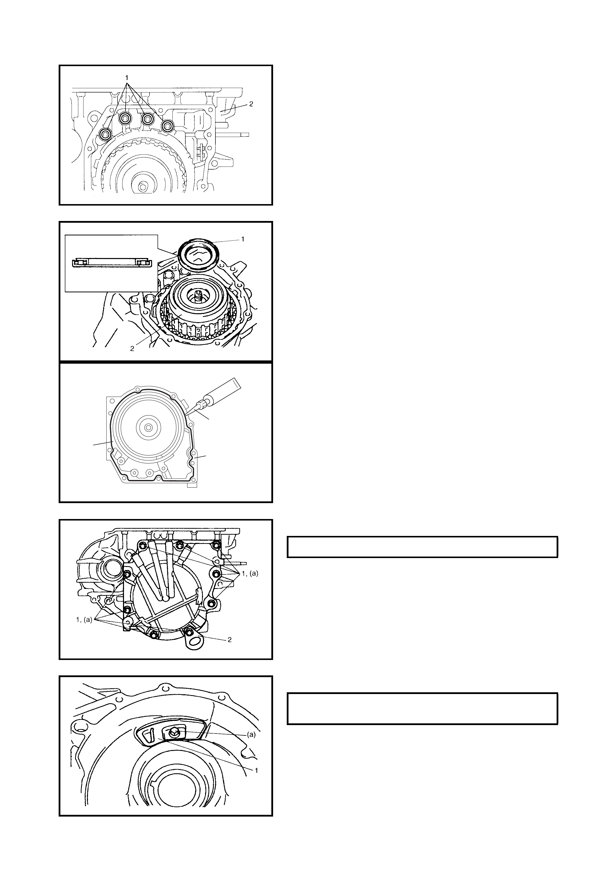
44. After applying A/T fluid to the new 2nd brake gaskets
(1), install them to the transaxle case (2).
45. After applying A/T fluid to the reverse clutch drum
thrust bearing (1), install it to the forward and reverse
clutch assembly (2).
46. Remove the sealant attached to the mating surface of
the transaxle re ar cove r (1 ) thorou ghly.
47. Apply sealant to the mating surface of the transaxle
rear cover (1) by using a nozzle (2) which will give a
sealant bead 1.2 mm in diameter as shown in the
figure.
“A”: Sealant Three Bond No. 1216B
48) Install transaxle rear cover assembly on transaxle
case.
49. Install hook (2) to location as shown in the figure.
50. Tighten the rear cover bolts (1).
51. Install the fluid reservoir LH plate (1).
“A”
2
1
REAR COVER BOLTS (a) 25 Nm
FLUID RESERVOIR LH PLATE BOLT (a)
TORQUE SPECIFICATION 10 Nm
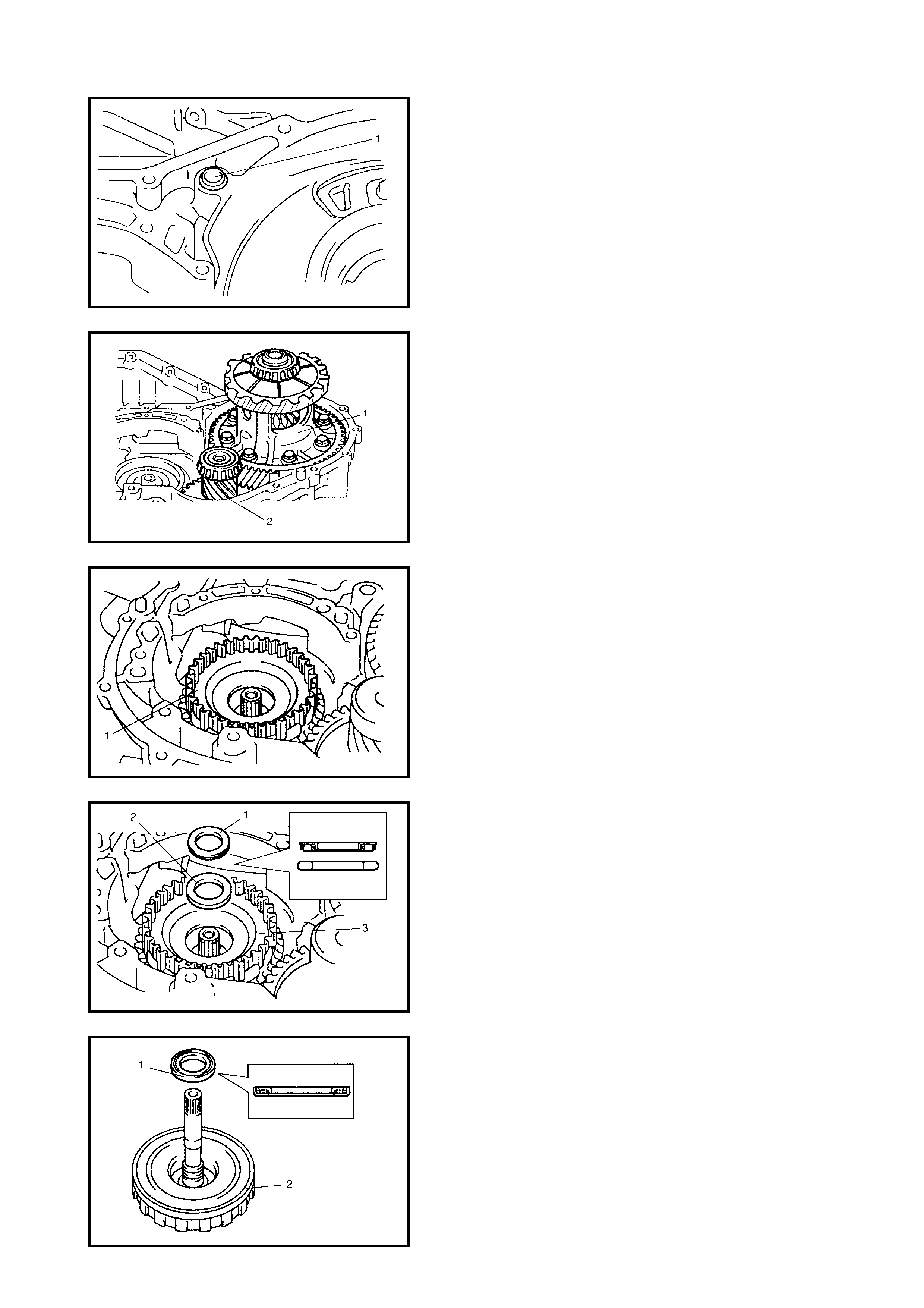
52. After applying A/T fluid to the new governor apply No.2
gasket (1), install it in the transaxle case.
53. After applying A/T fluid to the differential assembly (1)
and the countershaft assembly (2), install them to the
transaxle case.
54. After applying A/T fluid to the direct clutch hub (1),
install it to the planetary gear assembly.
55. After applying A/T fluid to the input shaft rear thrust
bearing (1) and thrust bearing race (2), install them into
the direct clutch hub (3).
56. After applying A/T fluid to the input shaft front thrust
bearing (1), install it to the direct clutch assembly (2).
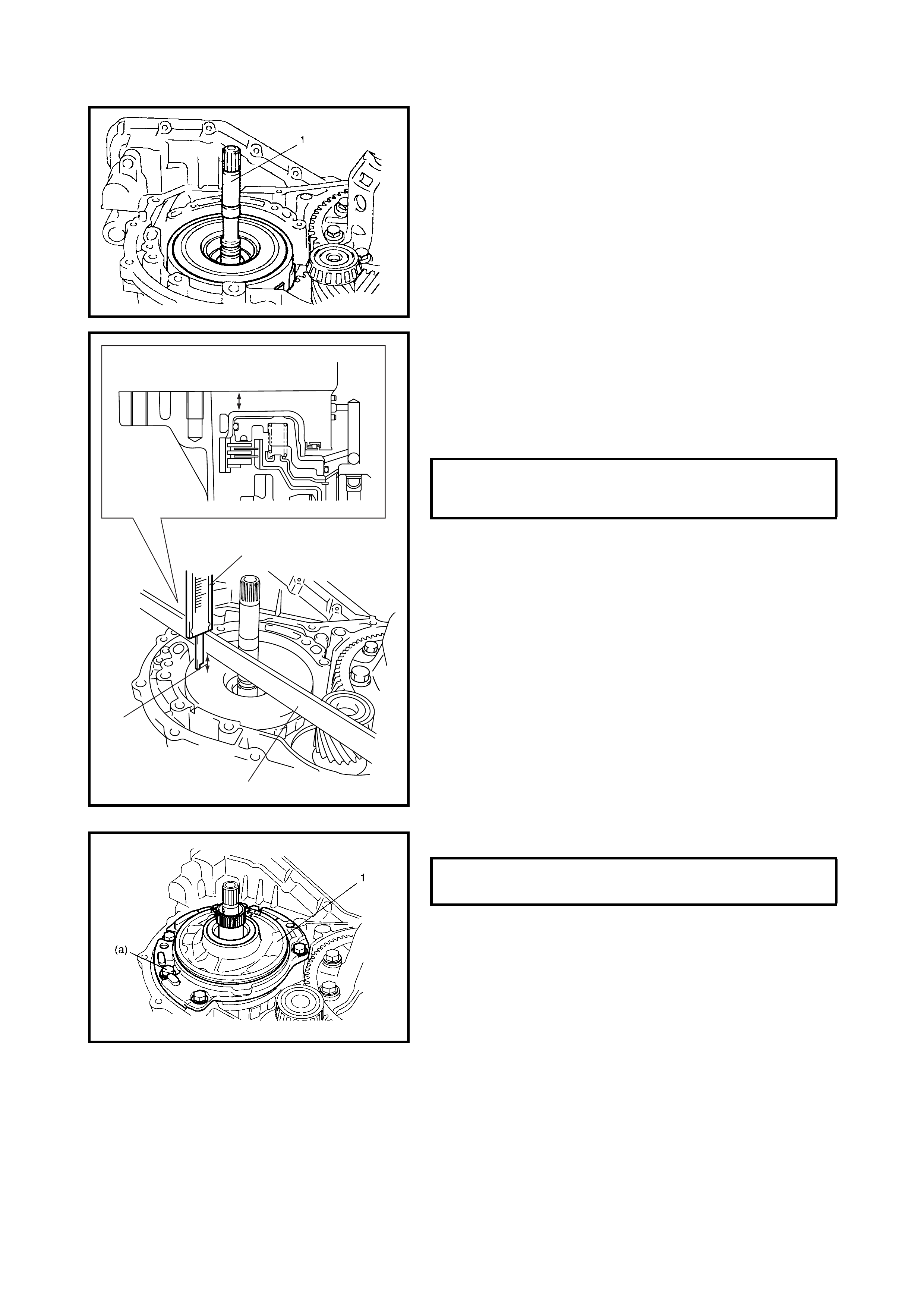
57. Apply A/T fluid to the direct clutch assembly (1).
Install the direct clutch assembly by rotating clockwise
and counter clockwise frequently to fit the clutch discs
to the mating hub.
NOTE: Before installation, align the teeth of the direct
clutch discs to ease installation.
58. Check for correct installation of the direct clutch
assembly as follows.
Measure distance “a ” by using a mic r om eter caliper (1)
and straighte dge (2). If out of speci fica tion , r emo ve th e
direct clutch assembly, direct clutch hub and reinstall
them correctly.
59. Install the oil pump assembly to the transaxle case.
DISTANCE BETWEEN DIRECT
CLUTCH ASSEMBLY AND MATING
SURFACE OF TRANSAXLE CASE (a) 10.4 - 11.4 mm
“a”
“a”
1
2
OIL PUMP ASSEMBLY BOLTS (a)
TORQUE SPECIFICATION 25 Nm
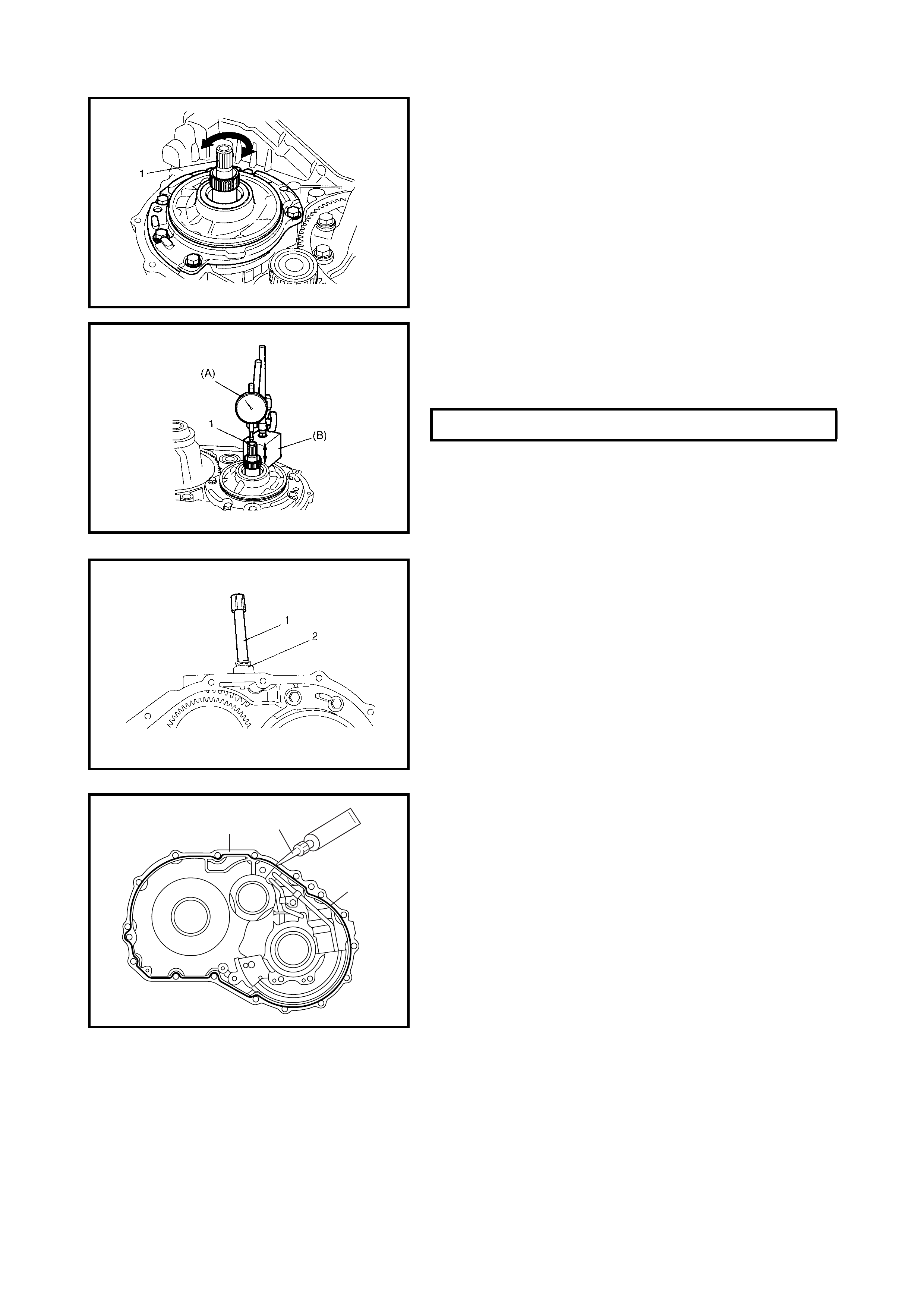
60. Make sure that the input shaft (1) turns smoothly.
61. Measure the input shaft thrust play.
Apply a dial gauge onto the input shaft end (1) and
measure the th ru st p lay of the i npu t sh aft usin g s pec ia l
tools 09900-20607 (A) and 09900-20701 (B).
62. After applying A/T fluid to the new O-ring, fit it to
breather union (2). Install the breather union to the
transaxle case.
63. Install the breather hose (1).
64. Wipe off and clean the mating surface between the
transaxle case (1) and the torque converter housing.
65. Apply sealant to the torque converter housing (1) using
a nozzle (2) which will give a sealant bead 1.2mm in
diameter as shown in the figure.
“A”: Sealant Three Bond No. 1216B
INPUT SHAFT THRUST PLAY 0.3 - 0.9 mm
12
“A”
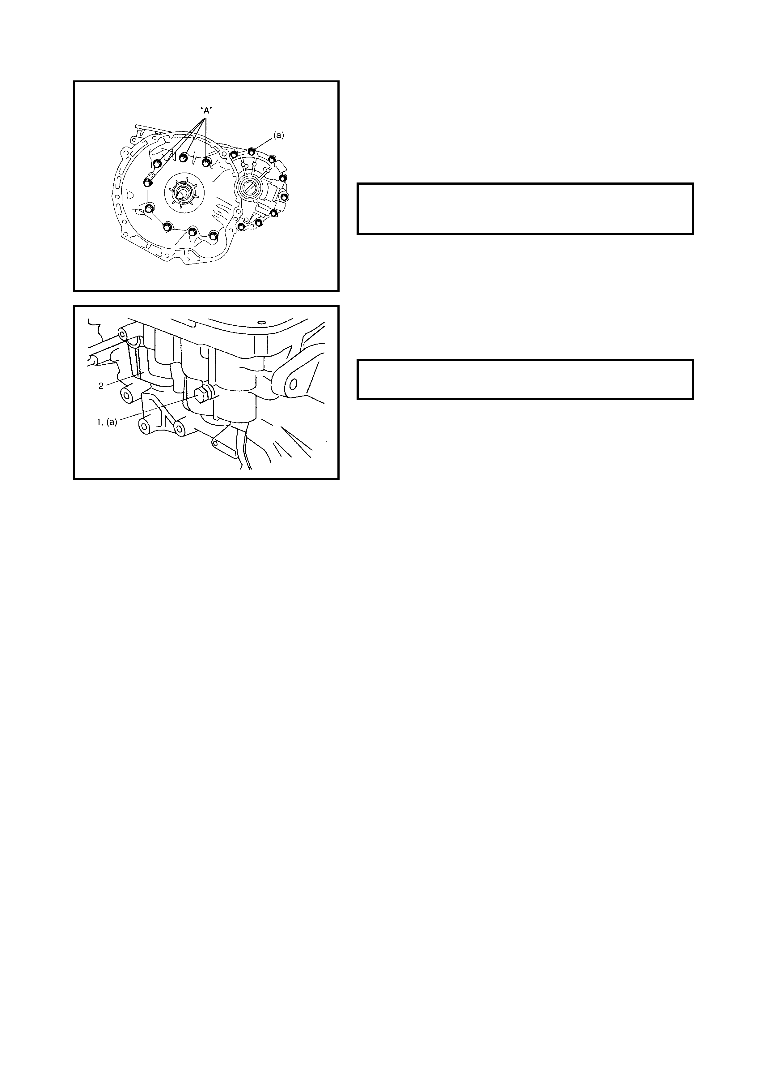
CAUTION: Apply sealant to the threads of the four
bolts as shown in the figure before tightening.
“A”: Sealant Three Bond No. 1216B
66. Install the torque converter housing to the transaxle
case, tighten bolts to specified torque.
67. After applying A/T fluid to the new O-ring, fit it to the
transaxle case plug (1).Install the transaxle case plug
to the transaxle case (2).
TORQUE CONVERTER HOUSING
BOLTS (a)
TORQUE SPECIFICATION 33 Nm
TRANSAXLE CASE PLUG (a)
TORQUE SPECIFICATION 7.5 Nm
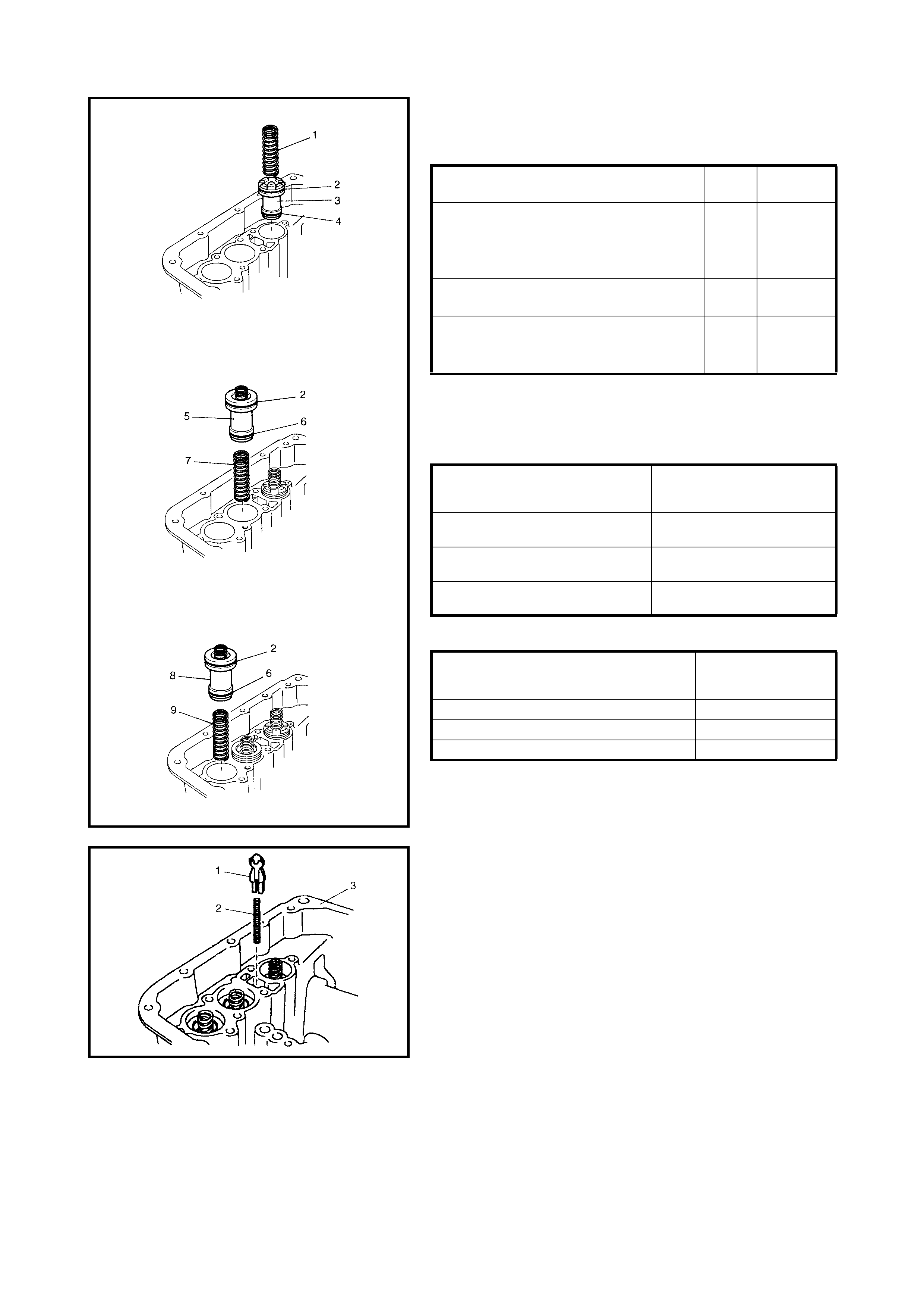
68. Install the new O-r ings to ea ch accumu lator piston and
apply A/T fluid to them.
Accumulator O-ring dimension
NOTE: Make sure that the O-rings are not twisted or
pinched when installing
.
69. Install B1, C1, C2 accumulator pistons and springs.
Accumul ator piston identification
Accumulator spring identification
70. After applying A/T fluid to the cooler check valve (1)
and spring (2 ), install them to the trans ax le case (3 ).
O-RING NAME INSIDE
DIA. SECTION
DIA.
B1 ACCUMULATOR O-RING (LARGE) (2)
C1 ACCUMULATOR O-RING (LARGE) (2)
C2 ACCUMULATOR O-RING (LARGE) (2)
(ABOVE THREE O-RINGS ARE SAME.) 29.4
mm 2.6 mm
B1 ACCUMULATOR O-RING (SMALL) (4) 19.7
mm 2.6 mm
C1 ACCUMULATOR O-RING (SMALL) (6)
C2 ACCUMULATOR O-RING (SMALL) (6)
(ABOVE TWO O-RINGS ARE SAME.) 21.8
mm 2.6 mm
PISTON NAME
IDENTIFICATION
(EMBOSSED LETTERS
ON PISTON)
B1 ACCUMULATOR PISTON
(3) SB-1
C1 ACCUMULATOR PISTON
(5) S2C-1
C2 ACCUMULATOR PISTON
(8) S2C-2
SPRING NAME
COLOUR OF
IDENTIFICATION
PAINT
B1 ACCUMULATOR NO.2 SPRING (1) PINK
C1 ACCUMULATOR NO.2 SPRING (7) LIGHT BLUE
C2 ACCUMULATOR NO.2 SPRING (9) YELLOW
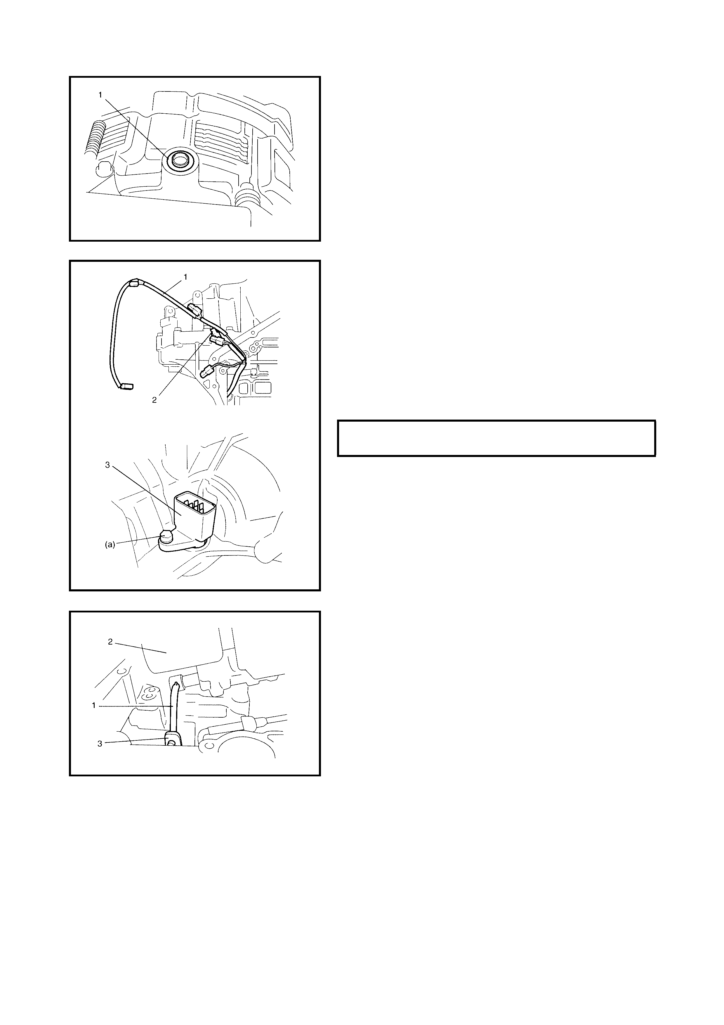
71. After applying A/T fluid to the new governor apply No.1
gasket (1), install it to the transaxle case.
CAUTION: When installing the valve body harness (1)
into the transaxle case, take care not to damage the
transmission fluid tempe rature sensor (2 ) at the narr ow
entrance to the case.
Careless s ensor tr eatment may cause se nsor malfun c-
tion.
72. After applying A/T fluid to the new O-ring, fit it to the
valve body harness connector (3), then install the valve
body harness to the transaxle case.
73. Install the manual valve rod (1) to the manual valve
lever (3) then install the valve body assembly (2) to the
transaxle case.
VALVE BODY HARNESS CONNECTOR
BOLT (a) 5.5 Nm
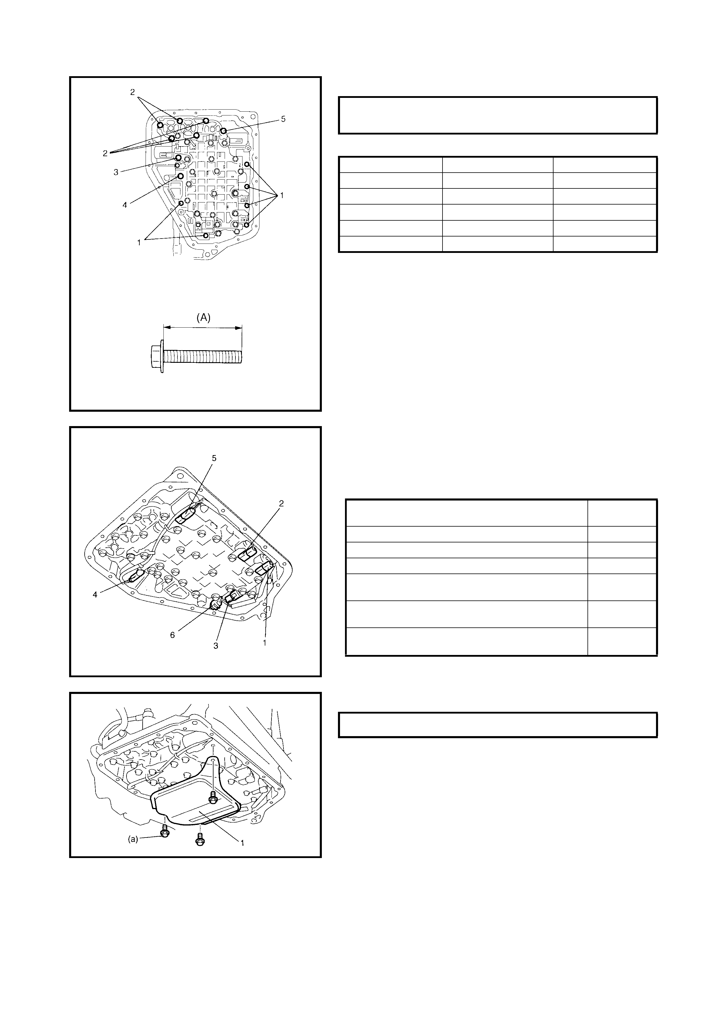
74. Tighten the valve body bolts to the specified torque.
Valve body bolt length
75. Connect the solenoid connectors to the solenoid
valves, identifying their installation positions by the wire
colours, then install the transmission fluid temperature
sensor to its clamp.
76. Install the oil strainer assembly (1).
VALVE BODY BOLTS
TORQUE SPECIFICATION 11 Nm
BOLT LENGTH (A) PIECES
A (1) 20 mm 6
B (2) 28 mm 5
C (3) 49 mm 1
D (4) 36 mm 1
E (5) 40 mm 1
SOLENOID VALVE CONNECTOR WIRE
COLOUR
SHIFT SOLENOID VALVE-A (1) WHITE
SHIFT SOLENOID VALVE-B (2) BLACK
TIMING SOLENOID VALVE (3) YELLOW
TCC (LOCK-UP) SOLENOID VALVE (4) LIGHT
GREEN
PRESSURE CONTROL SOLENOID VALVE (5) GRAY +
GREEN
TRANSMISSION FLUID TEMPERATURE
SENSOR (6) ORANGE
OIL STRAINER BOLTS (a) 10 Nm
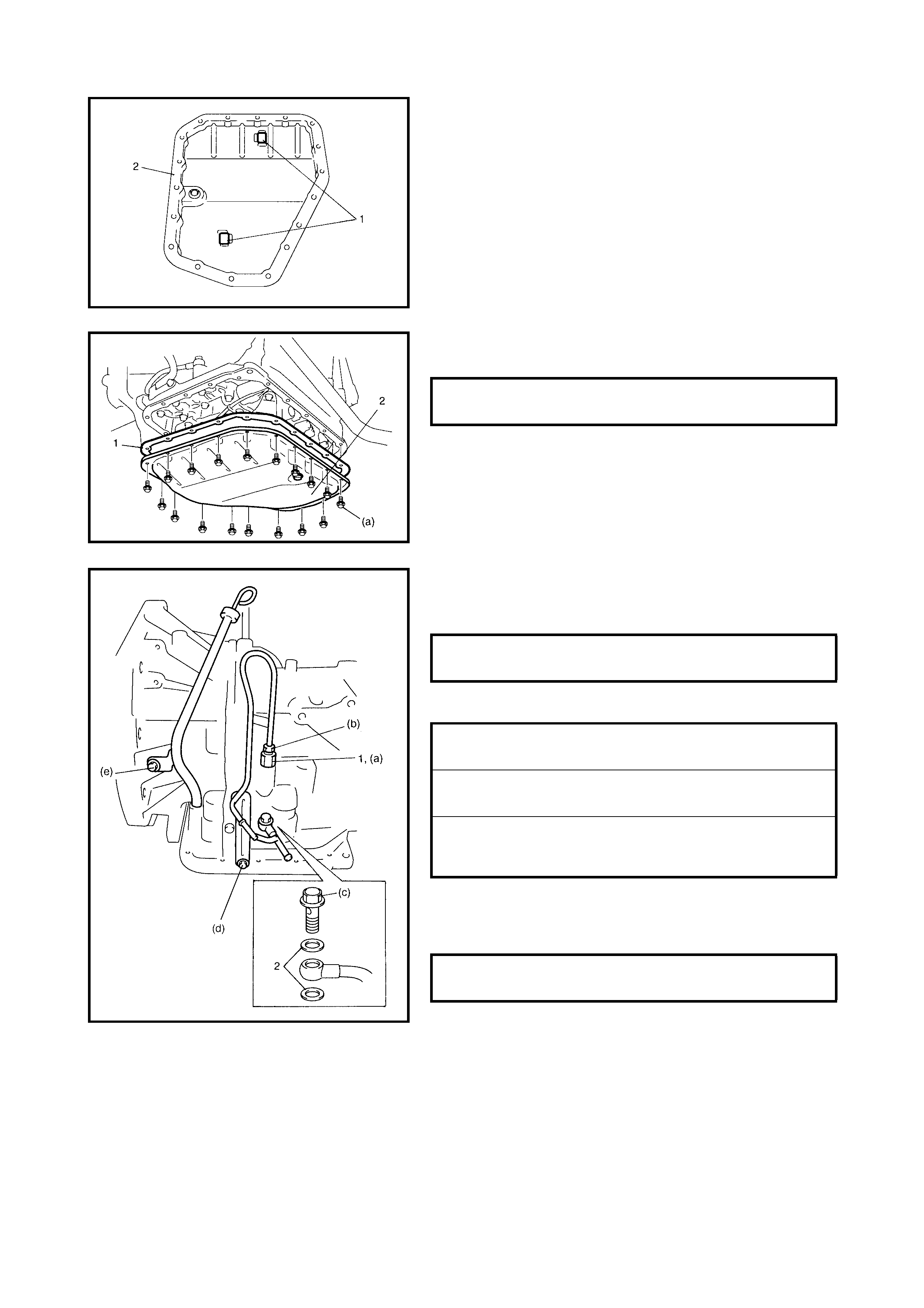
77. Install the oil cleaner magnets (1) in oil pan (2).
NOTE: If metal particles are attached to the magnets, clean
them before installing.
78. Install a new oil pan gasket (1) between the transaxle
case and the oil pan (2).
79. After applying A/T fluid to the new O-ring, fit it to the
fluid outle t union (1). Ins tall the fluid outlet uni on to the
transaxle case.
80. Install the new gasket then install the fluid cooler pipes.
81. After applying A/T fluid to the new O-ring, fit it to the
fluid filler tube. Install the fluid filler tube to the
transaxle case.
OIL PAN BOLTS (a)
TORQUE SPECIFICATION 7.0 Nm
FLUID OUTLET UNION (a)
TORQUE SPECIFICATION 25 Nm
FLUID COOLER PIPE FLARE NUT (b)
TORQUE SPECIFICATION 35 Nm
FLUID COOLER PIPE BOLT (c)
TORQUE SPECIFICATION 22 Nm
FLUID COOLER PIPE BRACKET
BOLT (d)
TORQUE SPECIFICATION 10 Nm
FLUID FILLER TUBE BOLT (e)
TORQUE SPECIFICATION 10 Nm
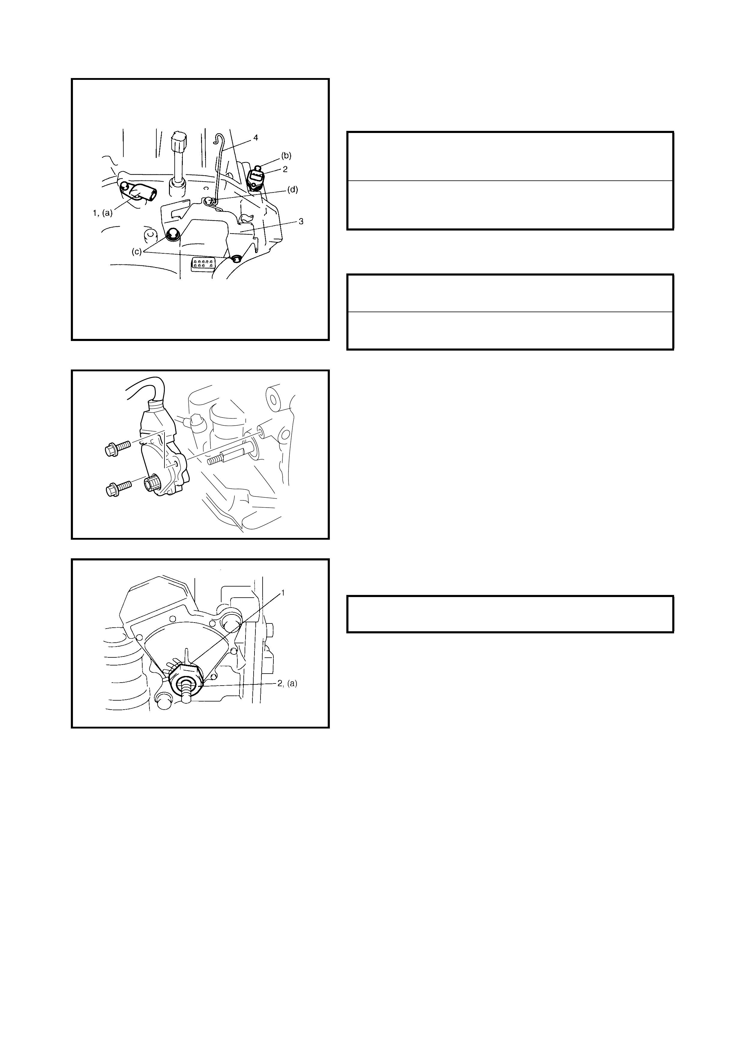
82. Apply A/T fluid to the O-rings of each sensor and install
the input shaft speed sensor (1) and the output shaft
speed sensor (VSS) (2).
83. Install the harness bracket (3) and the select cable
clamp (4).
84. Install the transmission range sensor to the transaxle
case, tighten bolts temporarily at this step.
85. Install the lock washer (1) and tighten the lock nut (2)
to specified torque.
INPUT SHAFT SPEED SENSOR BOLT
(a)
TORQUE SPECIFICATION 5.5 Nm
OUTPUT SHAFT SPEED SENSOR (VSS)
BOLT (b)
TORQUE SPECIFICATION 13 Nm
HARNESS BRACKET BOLTS (c)
TORQUE SPECIFICATION 23 Nm
SELECT CABLE CLAMP BOLT (d)
TORQUE SPECIFICATION 10 Nm
TRANSMISSION RANGE SENSOR
LOCK NUT (a) 7 Nm
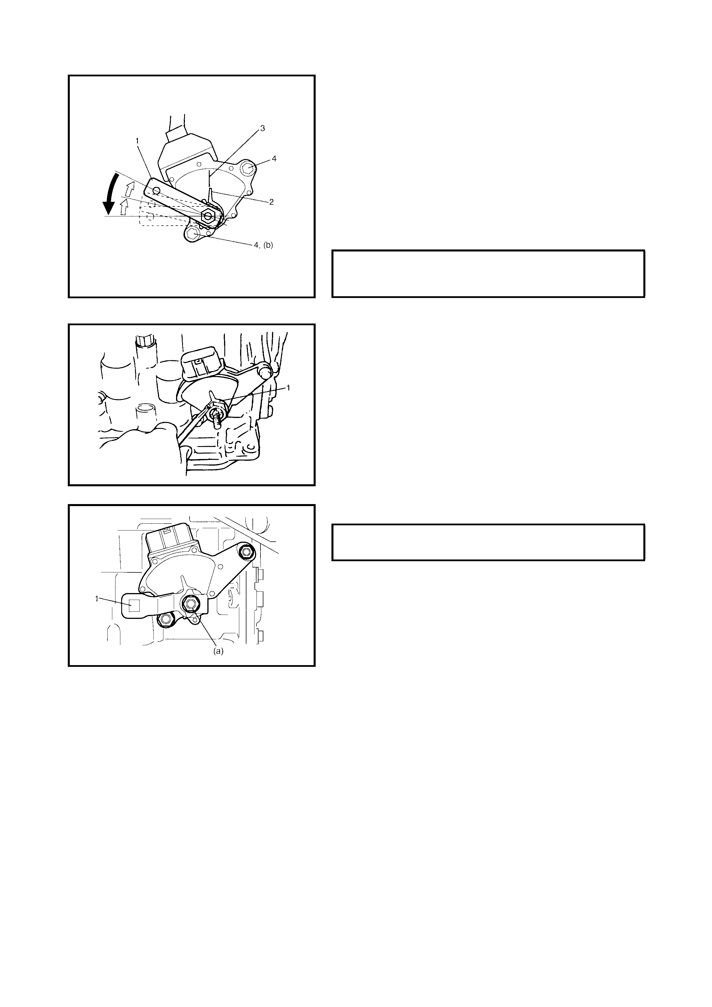
86. Install the manual select lever (1) temporarily at this
step.
87. After shifting the manual select lever fully counterclock-
wise, select the N range position by moving it back 2
notches clockwise.
88. Remove the manual select lever (1) at this step.
89. Loosen th e sensor b olts and al ign the ne edle dire ction
shaped on lock washer (2) with the N reference line (3)
on the transmission range sensor by moving the
sensor in circular direction.
90. Tighten the sensor bolts to specified torque.
91. Bend the dents of the lock washer (1) to secure in
position.
92. Install the manual select lever (1).
TRANSMISSION RANGE SENSOR
BOLTS (b)
TORQUE SPECIFICATION 5.5 Nm
MANUAL SELECT LEVER NUT (a)
TORQUE SPECIFICATION 13 Nm
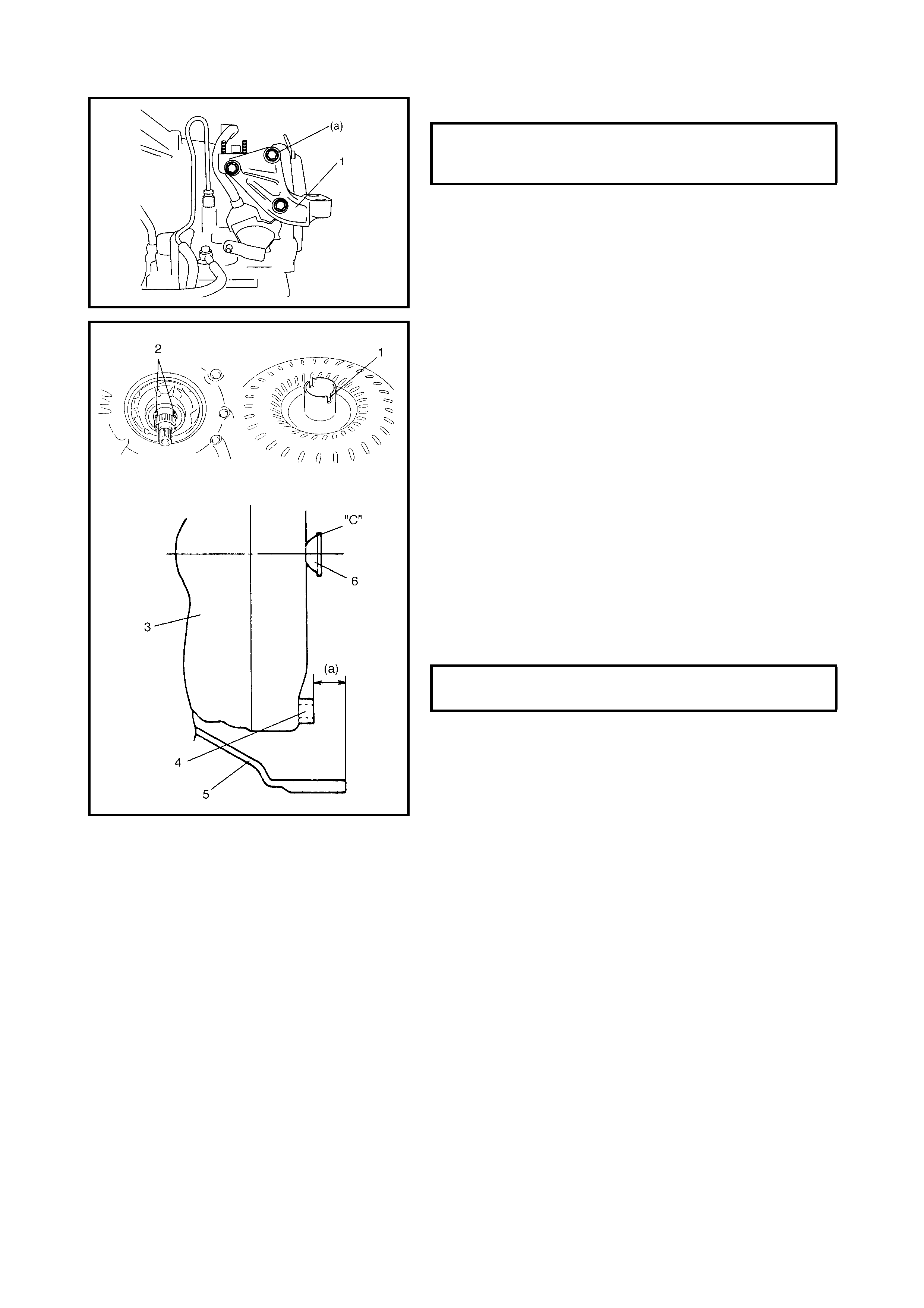
93. Install the engine mount LH bracket (1).
CAUTION:
• Before installing the torque converter, ensure its
pump hub portion is free from nicks, burrs or dam-
age which may cause the oil seal to leak.
• Do not drop the torque converter ont o the oil pump
gear.
Damage to the gear, may cause serious problems.
• Ins tall the tor que conver ter, alig ning the grooves (1) of
the torque converter and the projection (2) of the oil
pump drive gear.
• Install the torque converter (3), taking care not to the
damage oil seal on the oil pump.
• After ins talling the torq ue conver ter, che ck that the di s-
tance (a) (measured from the flange nut (4) to the
torque converter housing (5) mounting surface) is
within sp ec ifica t io n.
• Check the torque converter for smooth rotation.
• Apply grease around the cup (6) at the centre of the
torque converter.
“C”: Lithium grease
ENGINE MOUNT LH BRACKET BOLTS
(a)
TORQUE SPECIFICATION 50 Nm
TORQUE CONVERTER INSTALLING
POSITION (a) MORE THAN
19.9 mm
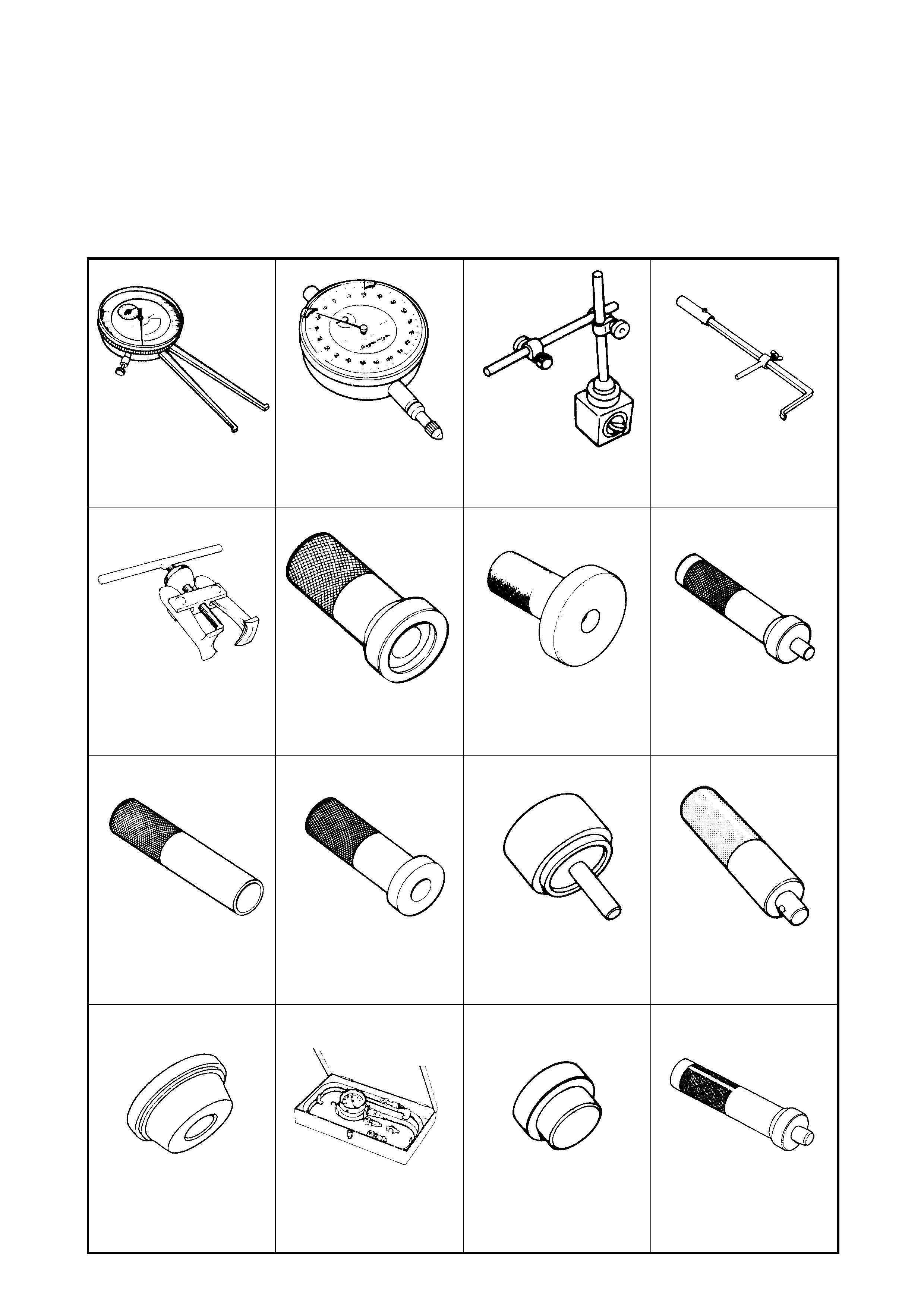
5. SPECIAL TOOLS
NOTE: Refer to Section 0A GENERAL INFORMATION — 7. CONSOLIDATED TOOLS for a detailed list of
special tools and the local equivalent if one is available.
09900-20605 09900-20607 09900-20701 09913-50121
Dial caliper gauge Dial gauge Magnetic stand Oil seal remover
09913-61510 09913-70123 09913-75520 09913-75821
Bearing puller Bearing installer Bearing installer Bearing installer handle
09913-84510 09913-85210 09923-78210 09924-74510
Bearing installer Bearing installer Bearing installer Bearing installer handle
09924-84510-002 09925-37811-001 09925-88210 09925-98210
Bearing installer Oil pressure gauge Bearing puller attachment Bearing installer
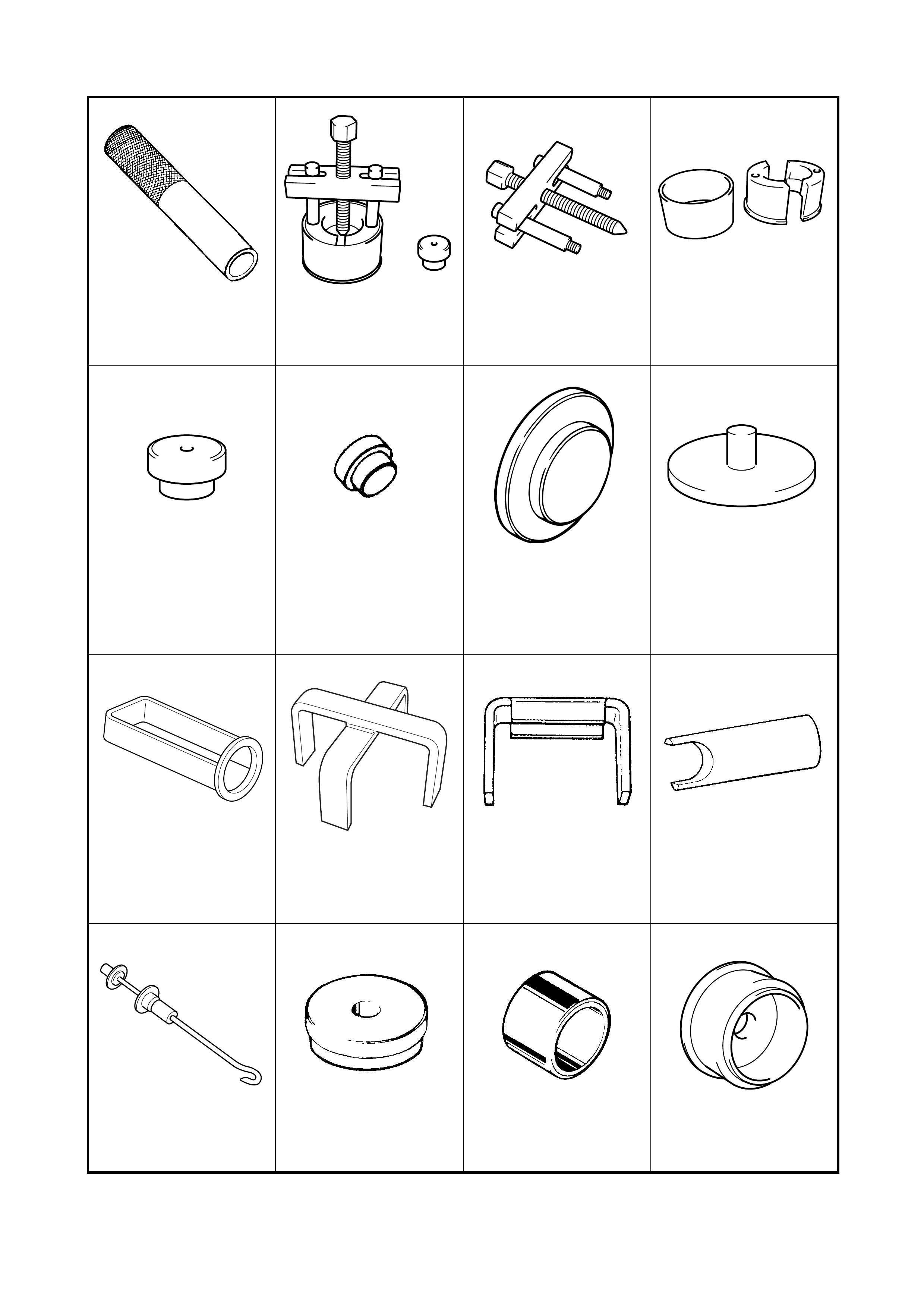
09925-98221 09926-37610 09926-37610-001 09926-37610-002
Bearing installer Bearing remover
See NOTE 1. Bearing puller
See NOTE 2. Bearing pul ler att achment
See NOTE 2.
09926-37610-003 09926-58010 09926-96030 09926-96050
Bearing remover attach-
ment
See NOTE 2.
Bearing remover attach-
ment Clutch spring compressor Brake piston compressor
09926-97610 09926-97620 09926-98310 09928-06050
Spring compressor Spring compressor Clutch spring compressor Differential preload
adapter
09942-15511 09944-68210 09944-78210 09944-88220
Sliding hammer Bearing installer Bearing installer support Oil seal installer
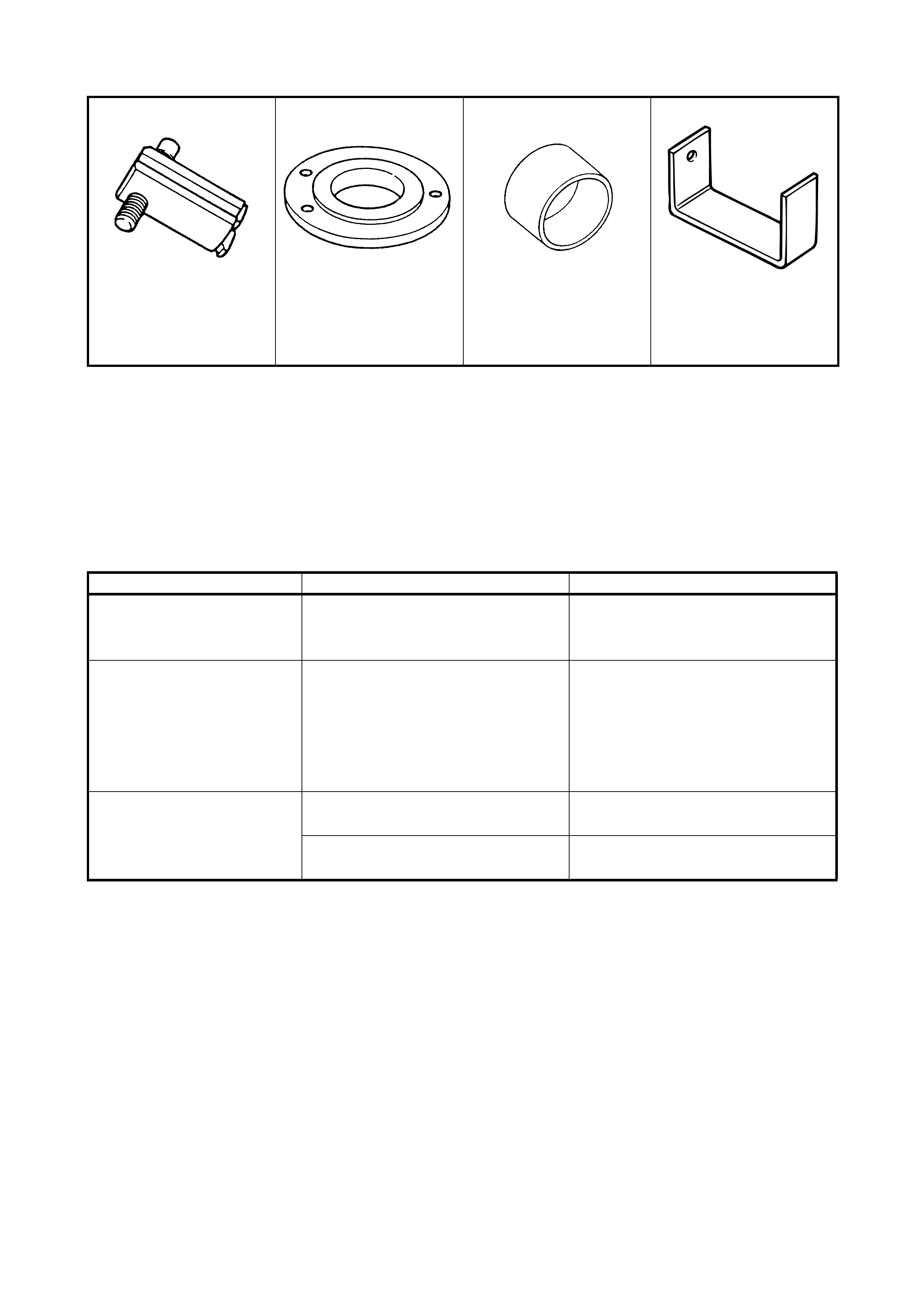
NOTE:
• “1”: This tool consists of Bearing Puller with 09926-37610-001, Bearing Puller Attachment with 09926-
37610-002 and Bearing Remover Attachment with 09926-37610-003.
• “2”: This tool is constituent of Bearing Remover with 09926-37610.
6. REQUIRED SERVICE MATERIAL
09944-96011 09946-06710 09951-18210 09952-06020
Bearing outer race
remover Bearing retainer dummy Oil seal installer Dial gauge plate No.2
Material Recommended product Use
Automatic transmission fluid An equivalent of DEXRON
®
-III
• Automatic transaxle
• Parts lubrication when installing
• O-rings
Sealant Three Bond No. 1216B
• Mating sur face of torque con-
verter ho usi ng
• Mating surface of rear cover
assembly
• Torque converter housing bolts
• Drive plate bolts
Lithium grease Lithium Grease
• Oil seal lips
• Pl an etary carrie r th rus t wa she r
Lithium Grease
• Cable ends
• Converter centre cup