
7B
WARNING:
For vehicles equipped with a Supplemental Restraint (Air Bag) System:
• Service on and around the air bag system components or wiring must be performed only by an
authorized Holden dealer. Refer to “System Components and Wiring Location View and
Connectors” under “General Description” in Section 10B in order to confirm whether you are
performing service on or near the air bag system components or wiring. Please observe all
WARNINGs and “Service Precautions” under “On-Vehicle Service” in Section 10B before
performing service on or around the air bag system components or wiring. Failure to follow
WARNINGs could result in unintentional activation of the system or could render the system
inoperative. Either of these two conditions may result in severe injury.
• Technical service work must be started at least 90 seconds after the ignition switch is turned to
the “LOCK” position and the negative cable is disconnected from the battery. Otherwise, the
system may be activated by reserve energy in the Sensing and Diagnostic Module (SDM).
NOTE:
For the items not listed below, refer to the Section 7B.
General Description
Specifications
Transmission Control Module (TCM)
Automatic Gear Shift Diagram
Diagnosis
Diagnostic Trouble Code (DTC) Table
Manual Road Test
SECTION 7B1 - AUTOMATIC TRANSAXLE (2004 UPDATE)
General Description
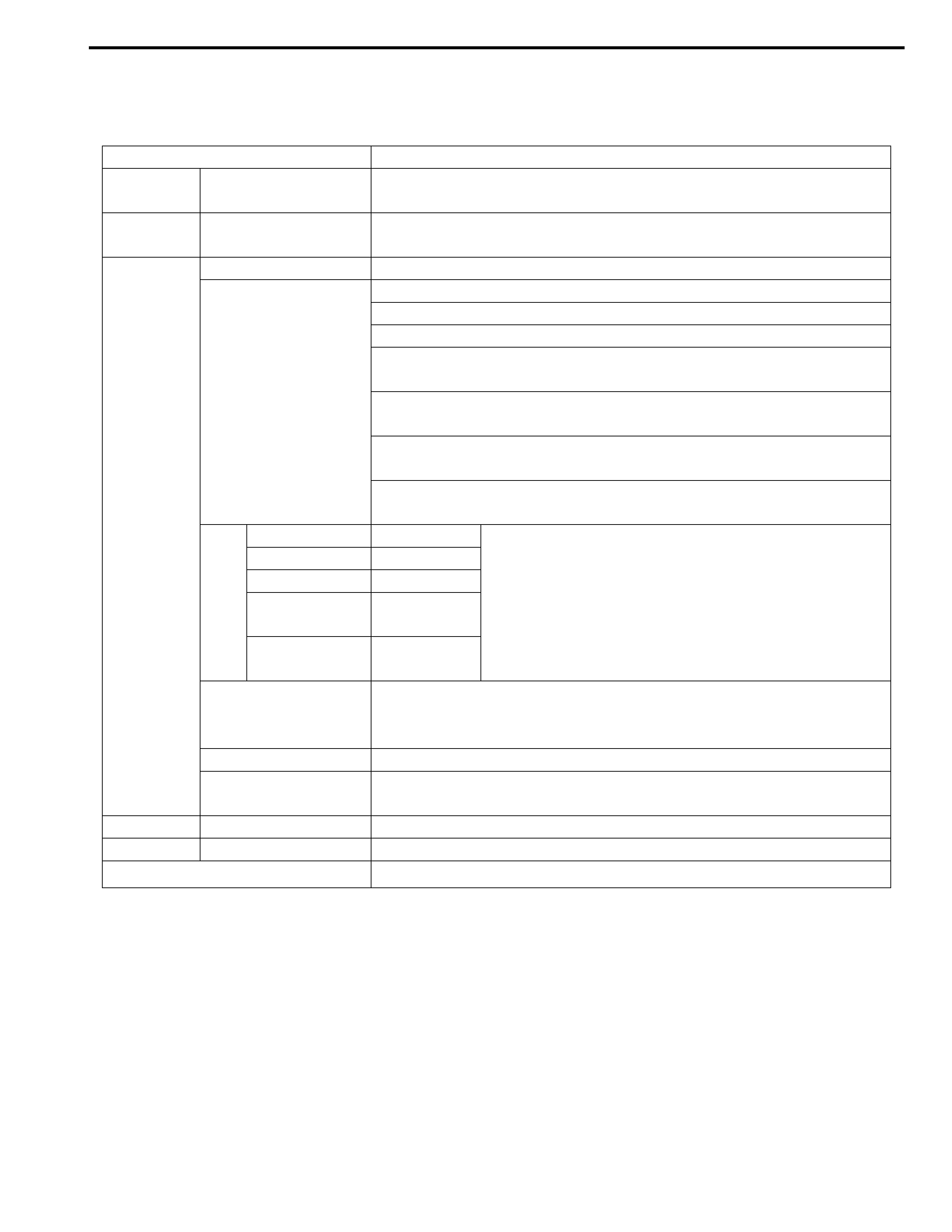
Specifications
Item Specifications
Torque
converter
Typ e
Stall torque ratio
3-element, 1-step, 2-phase type (with TCC (lock-up) mechanism)
1.9 – 2.1
Oil pump Ty p e
Drive system
Internal involute gear type oil pump (non crescent type)
Engine driven
Gear
change
device
Type Forward 4-step, reverse 1-step planetary gear type
Shift position
“P” range Gear in neutral, output shaft fixed, engine start
“R” range Reverse
“N” range Gear in neutral, engine start
“D” range
(O/D ON)
Forward 1st ↔ 2nd ↔ 3rd ↔ 4th (O/D)
automatic gear change
“D” range
(O/D OFF)
Forward 1st ↔ 2nd ↔ 3rd ← 4th
automatic gear change
“2” range Forward 1st ↔ 2nd ← 3rd
automatic gear change
“L” range Forward 1st ← 2nd ← 3rd reduction, and fixed at 1st
gear
Gear
ratio
1st 2.875 Number of teeth Front sun gear: 24
2nd 1.568 Rear sun gear: 30
3rd 1.000 Long planet pinion: 20
4th
(overdrive gear) 0.697 Short planet pinion: 19
Ring gear: 69
Reverse
(reverse gear) 2.300
Control elements
Wet type multiple-disc clutch... 3 sets
Wet type multiple-disc brake... 3 sets
One-way clutch... 2 sets
Reduction gear ratio 1.022
Final gear reduction
ratio 4.277
Lubrication Lubrication system Force feed system by oil pump
Cooling Cooling system Radiator assisted cooling (water-cooled)
Fluid used DEXRON-III
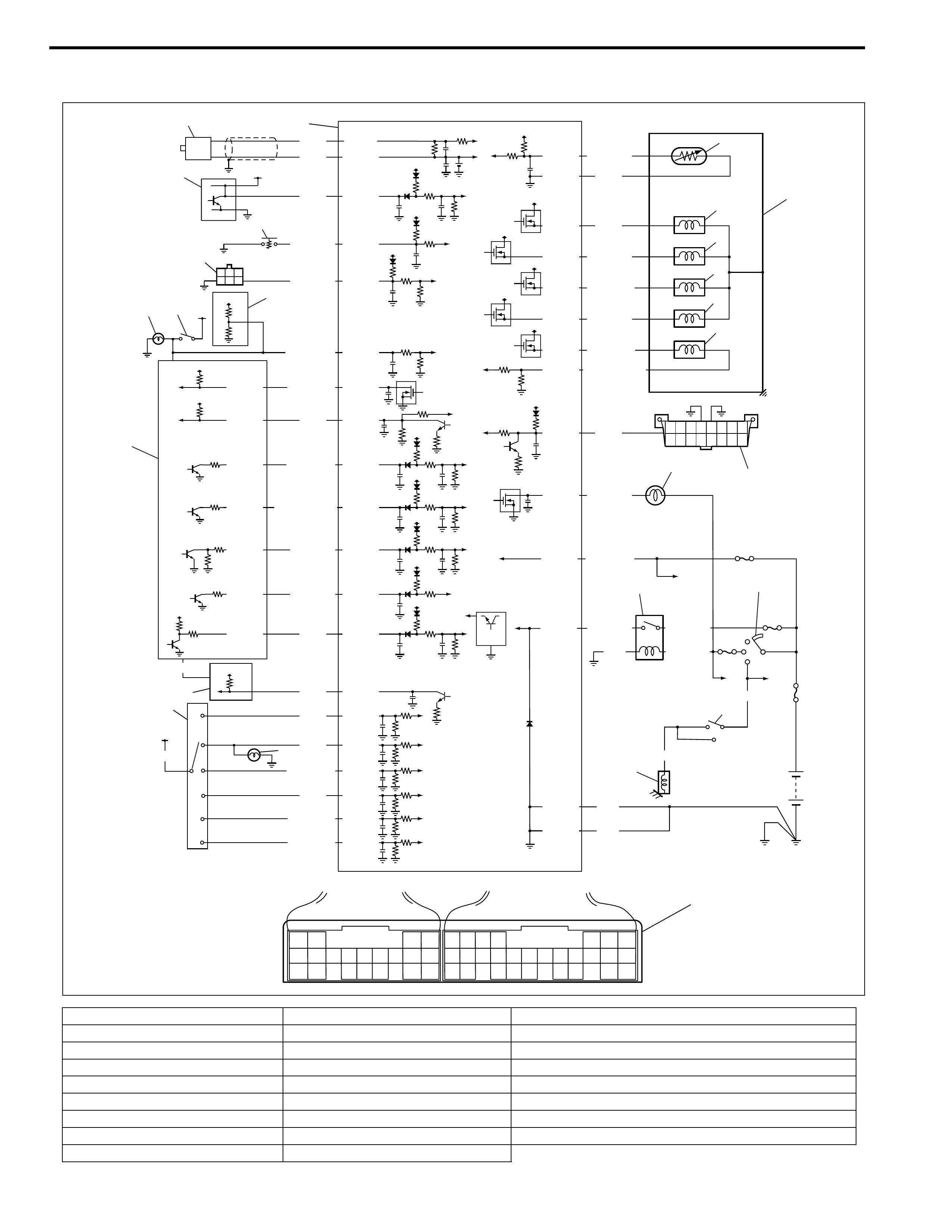
Transmission Control Module (TCM)
1. TCM 10. Speedometer (in combination meter) 19. A/T
2. Input shaft speed sensor 11. Transmission range sensor 20. Data link connector (DLC)
3. Output shaft speed sensor (VSS) 12. Backup lamp 21. “O/D OFF” lamp
4. O/D off switch 13. Transmission fluid temperature sensor 22. A/T relay
5. Monitor connector (color in Black) 14. Shift solenoid valve-A (No.1) 23. Ignition switch
6. Brake light (Stop lamp) 15. Shift solenoid valve-B (No.2) 24. Inhibitor switch
7. Brake light switch (Stop lamp switch) 16. Timing solenoid valve 25. Starter motor relay
8. ABS control module 17. TCC (lock-up) solenoid valve 26. Terminal arrangement of TCM connector (viewed from harness)
9. ECM 18. Pressure control solenoid valve
43
13 12 11 10 9 8
20 19 18 17 16
76 5
21
15 14
19 18
28 27
17 16
7654
15 14
26 25 24
13 12 11
23 22
10 9 8
21 20
321
C43 G99
5
IG1
+BB
4
12V
12V
12V
12V
12V
11
10
P
R
N
D
2
L
12
PPL/YEL
GRN/WHT
GRN/RED
GRY/RED
LT GRN/RED
RED/BLU
G99-5
12V 2.5V
12V
5V
12V
12V
12V
12V
12V
5V
12V
12V
12V
12V
12V
12V
IG11
IG1
24
25
12V
WHT
BLK
GRN
BRN
BLK
BLK
BLK
BLU
YEL
PNK
BRN
PPL
PPL
ORN
RED
GRN
GRY/YEL
YEL/GRN
GRN/ORN
GRN/YEL
IG11
RED/BLK
BLU/WHT
G99-17 C43-5
C43-14
C43-4
C43-3
C43-10
C43-12
C43-11
C43-8
G99-27
G99-10
C43-15
C43-19
C43-20
G99-24
G99-3
C43-6
C43-16
G99-12
G99-18
G02-6
G02-17
G02-15
G02-5
G02-4
G02-16
G02-12
G99-7
G99-6
G99-23
G99-14
G99-15
G99-28
G99-2
G99-1
G99-9
G99-8
G99-21
G99-20
BLU/RED
BLK/YEL
WHT/RED
WHT/BLU
RED/BLU
YEL/BLK
YEL/GRN
BLK/WHT
+BB
C43-13 WHT/RED
BLK/YEL
BLK/RED
BRN/YEL
LT GRN/RED
P
N
13
19
14
15
16
17
18
1
2
3
8
7
6
9
20
21
22 23
26
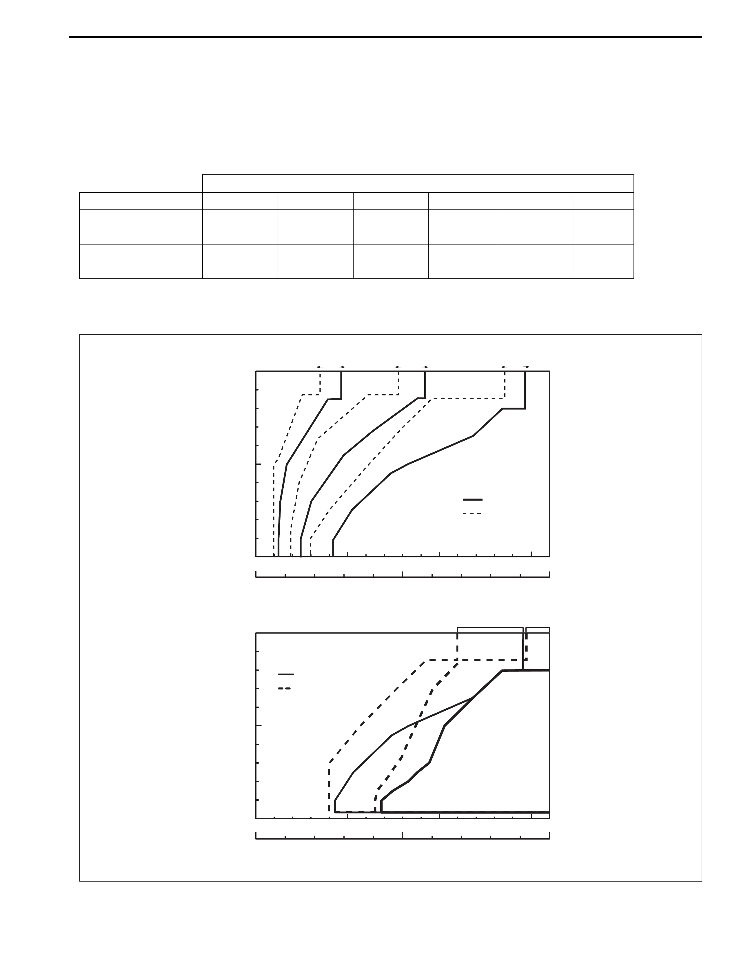
Automatic Gear Shift Diagram
Automatic shift schedule as a result of shift control is shown below. In case that selector lever is shifted to “L”
range at a higher than 46 km/h (29 mile/h) speed, 2nd gear is operated and then down shifts to 1st at a speed
lower than that.
The same as, the select lever is shifted to “2” range at a higher than 92 km/h (57 mile/h) speed, 3rd gear is oper-
ated and then down shifts to 2nd at a speed lower than that.
Gear Shift Diagram [A] and TCC Lock-up Diagram [B]
Shift
Throttle opening 1→22→33→44→33→22→1
Full throttle km/h
(mile/h)
46 (29) 92 (57) 146 (91) 136 (85) 78 (48) 35 (22)
Closed throttle km/h
(mile/h)
12 (8) 24 (15) 42 (26) 30 (17) 19 (12) 10 (6)
100
(%)
50
00 50 100 150
100
(km/h)
(mile/h)500
Throttle valve opening
Vehicle speed
100
(%)
50
00 50 100 150
100
(km/h)
(mile/h)500
Throttle valve opening
Vehicle speed
12
12 23 23 34
34
Upshift
Downshift
Look-up ON
Look-up OFF
4th gear3rd gear(O/D OFF)
[A]
[B]
Diagnosis
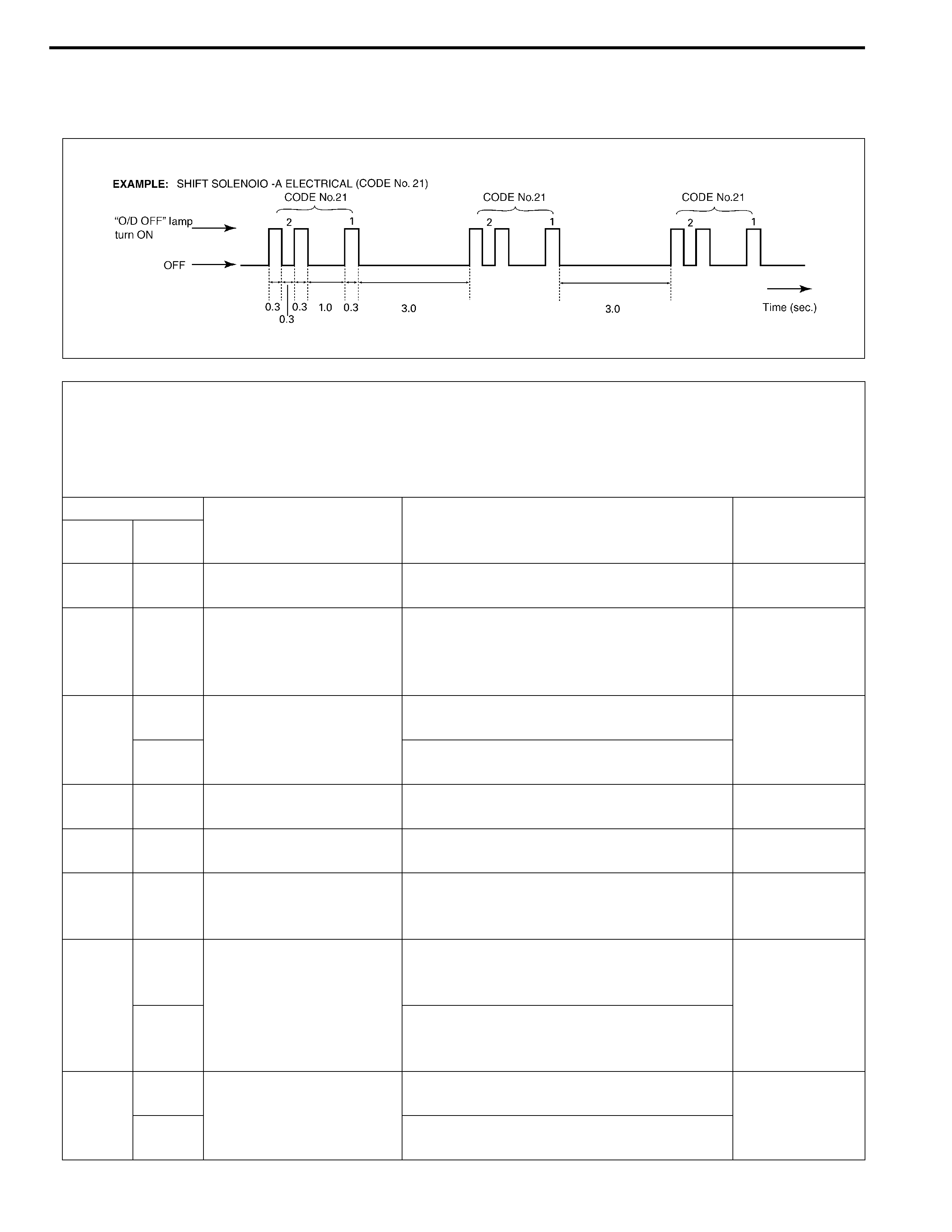
Diagnostic Trouble Code (DTC) Table
NOTE:
• Type I of DTC: DTC code which can be checked by using scan tool
• Type II of DTC: DTC code which can be checked by flashing “O/D OFF” lamp in combination meter
with monitor connector diagnosis terminal connected to ground.
• *1: Application of “O/D OFF” lamp flashing by TCM when the malfunction is detected.
DTC NO.
DETECTING ITEM DETECTING CONDITION
(DTC will set when detecting:)
*1
“O/D OFF”
lamp flashing
Type I Type II
–12
Normal (No malfunction is
detected.) ––
P0705 34 Transmission range sen-
sor circuit malfunction
• No sensor signal is inputted.
or
• Multiple signals are inputted simulta-
neously
Not applicable
P0710
36 Transmission fluid tem-
perature sensor circuit
malfunction
Sensor output voltage is too high (Circuit
open or shored to power circuit) Applicable
38 Sensor output voltage is too low (Circuit
shored to ground)
P0715 14 Input/Turbine speed sen-
sor circuit malfunction
No sensor signal is detected although output
shaft speed sensor signal is detected. Applicable
P0720 31 Output speed sensor
(VSS) circuit malfunction
No sensor signal is inputted although input
shaft speed sensor signal is inputted. Applicable
P0725 35 Engine speed input cir-
cuit malfunction
No engine speed signal is inputted although
engine is running and engine temperature
sensor signal is in normal condition.
Applicable
P0743
25
Torque converter clutch
system electrical
Voltage of TCC solenoid terminal is high
although TCM is commanding TCC solenoid
to turn OFF. Applicable
26
Voltage of TCC solenoid terminal is low
although TCM is commanding TCC solenoid
to turn ON.
P0748
41 Pressure control solenoid
electrical
No electric flow is detected on solenoid cir-
cuit. Applicable
42 Too much electric flow is detected on pres-
sure control solenoid circuit.

DTC NO.
DETECTING ITEM DETECTING CONDITION
(DTC will set when detecting:)
*1
“O/D OFF”
lamp flashing
Type I Type II
P0753
21
Shift solenoid-A (No.1)
electrical
Voltage of shift solenoid terminal is high
although TCM is commanding shift solenoid
to turn OFF. Applicable
22
Voltage of shift solenoid terminal is low
although TCM is commanding shift solenoid
to turn ON.
P0758
23
Shift solenoid-B (No.2)
electrical
Voltage of shift solenoid terminal is high
although TCM is commanding shift solenoid
to turn OFF. Applicable
24
Voltage of shift solenoid terminal is low
although TCM is commanding shift solenoid
to turn ON.
P0785 13 Timing solenoid
• Voltage of timing solenoid terminal is high
although TCM is commanding timing sole-
noid to turn OFF.
or
• Voltage of timing solenoid terminal is low
although TCM is commanding timing sole-
noid to turn ON.
Applicable
P1700
32 Throttle position signal
circuit malfunction
Too short low signal of pulse signal from
ECM to TCM continues out of specification. Applicable
33 Too long low signal of pulse signal from ECM
to TCM continues out of specification.
P1702 52 Internal malfunction of
TCM
Calculation of current data stored in TCM is
not correct comparing with pre-stored check-
ing data in TCM.
Applicable
P1705 51
Engine coolant tempera-
ture signal circuit malfunc-
tion
• Too long high signal of pulse signal from
ECM to TCM continues out of specifica-
tion.
or
• Too long low signal of pulse signal from
ECM to TCM continues out of specifica-
tion.
or
• Too long or short low signal of pulse signal
from ECM to TCM is detected in continu-
ous 8 pulses.
Applicable
P1730 64 Engine torque signal cir-
cuit malfunction
• Too short low signal of pulse signal from
ECM to TCM continues out of specifica-
tion.
or
• Too long low signal of pulse signal from
ECM to TCM continues out of specifica-
tion.
Applicable
P1895 27 Torque reduction signal
circuit malfunction
Voltage of torque reduction signal circuit ter-
minal is low although TCM does not require
ECM to reduce engine torque
Applicable
Manual Road Test
This test checks the gears being used in “L”, “2” or “D” range
when driven with unoperated gear shift control system. Test drive
vehicle on a level road.
1) With select lever in “P”, start engine and warm it up.
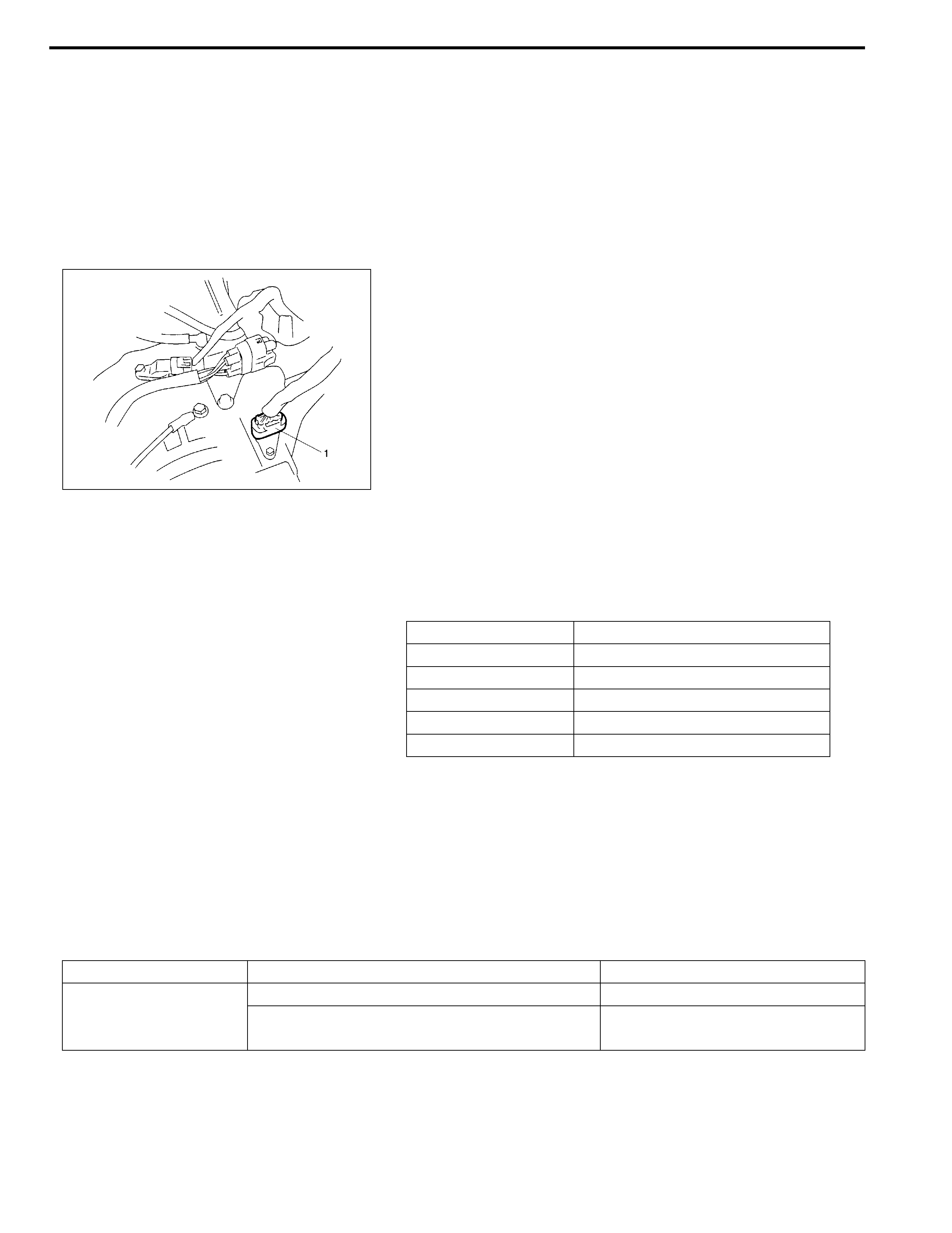
2) After warming up engine, turn ignition switch OFF and dis-
connect valve body harness connector (1).
3) With select lever in “L” range, start vehicle and check that 3rd
gear is being used referring to table shown below.
Vehicle speed per 1000 rpm in engine speed (V1000 table,
reference)
4) While vehicle is running, shift select lever to “2” range and
check that 3rd gear is being used.
5) While vehicle is running, shift select lever to “D” range and
check that 3rd gear is being used.
6) After above checks, stop vehicle then turn ignition switch
OFF, and connect valve body harness connector.
7) Clear DTC.
Troubleshooting
NOTE:
Before this test, check diagnostic trouble code (DTC).
Gear position Vehicle speed
1st 8.8 km/h (5.5 mile/h)
2nd 16.2 km/h (10.1 mile/h)
3rd 25.4 km/h (15.8 mile/h)
4th (O/D) 36.5 km/h (22.7 mile/h)
Reverse 11.0 km/h (6.8 mile/h)
Condition Possible Cause Correction
Operated gear is not
correct
Faulty valve body component Replace valve body assembly.
Faulty clutch or brake Inspect clutch and brake. If any
parts are faulty, replace them.