
SECTION 7C - CLUTCH
1. GENERAL DESCRIPTION
2. DIAGNOSIS
3. ON-VEHICLE SERVICE
3.1 CLUTCH CABLE
Removal
Inspection
Installation
3.2 CLUTCH PEDAL AND CLUTCH PEDAL
BRACKET
Clutch Pedal Height
Clutch Pedal Free Travel
4. UNIT REPAIR OVERHAUL
4.1 CLUTCH COVER, CLUTCH DISC AND
FLYWHEEL
Removal
Inspection
Installation
4.2 CLUTCH RELEASE SYSTEM
Removal
Inspection
Installation
5. REQUIRED SERVICE MATERIAL
6. SPECIAL TOOLS
WARNING:
For vehicles equipped with Supplementary Restraint (Airbag) System:
• Service on and around the airbag system components or wiring must be performed only by an
authorised HOLDEN retailer. Refer to AIRBAG SYSTEM COMPONENTS and WIRING LOCATION
VIEW under GENERAL DESCRIPTION in Section 10B AIRBAG SYSTEM in order to confirm
whether you are performing service on or near the airbag system components or wiring. Please
observe all WARNINGS and SERVICE PRECAUTIONS under ON-VEHICLE SERVICE in Section
10B AIRBAG SYSTEM before performing service on or around the airbag system components or
wiring. Failure to follow WARNINGS could result in unintentional activation of the system or could
render the system inoperative. Either of these two conditions may result in severe injury.
• Technical service work must be started at least 90 seconds after the ignition switch is turned to
the “LOCK” position and the negative cable is disconnected from the battery. Otherwise, the sys-
tem may be activated by reserve energy in the Sensing and Diagnostic Module (SDM).
Techline
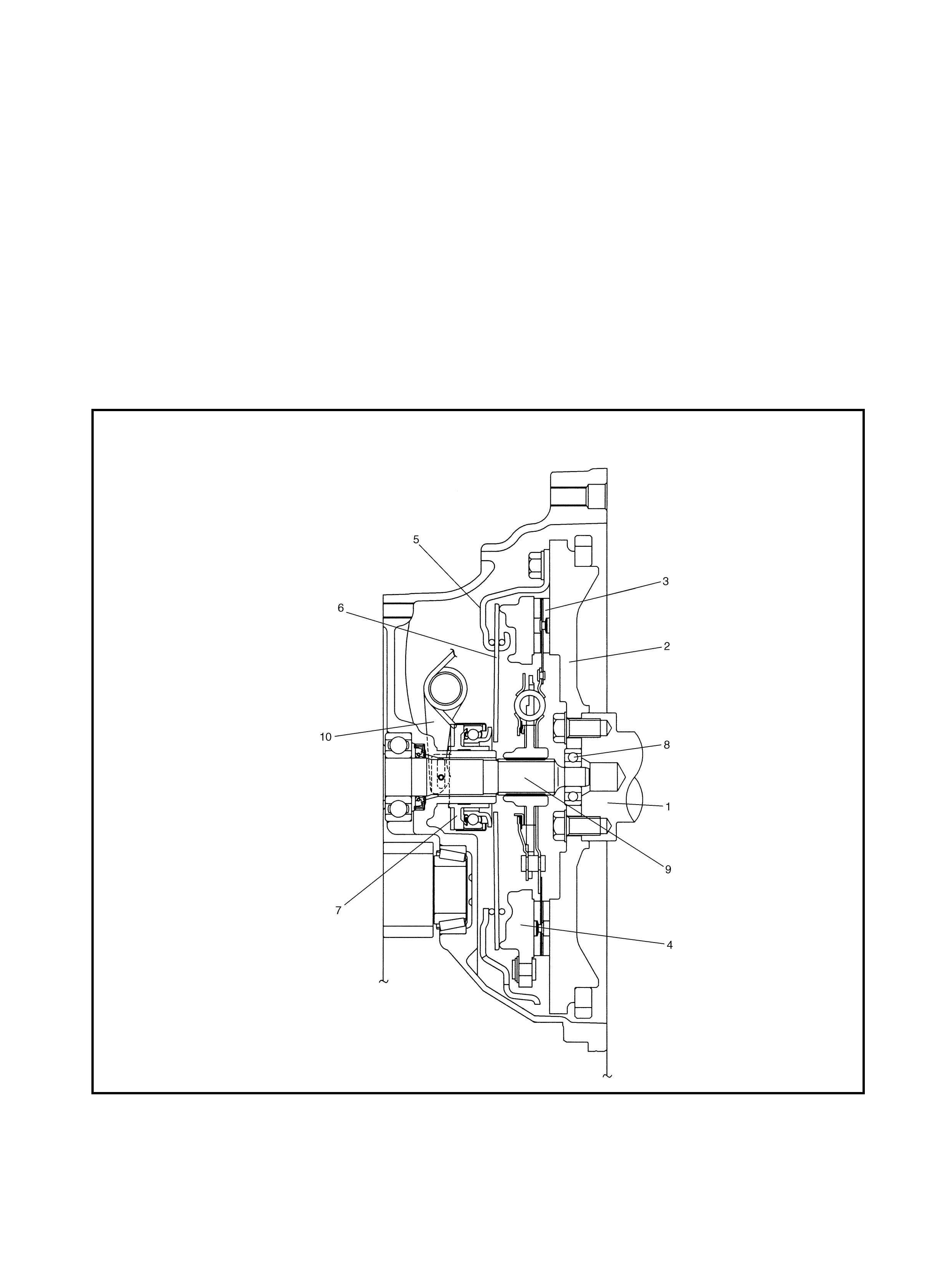
1. GENERAL DESCRIPTION
A dry single disc, diaphragm-spring clutch is fitted. The clutch disc incorpor ates four torsional coil springs and
is positioned on the spl ined transaxle input shaft.
The clutch cover, w hich is secured to the fl ywh eel, suppor ts the tapered-finger diaphragm spring. While the
clutch release bearing is not engaged, the peripheral part of the spring holds the pressure plate under ten-
sion, secur ing the clutch disc to the flywheel. This is the engaged condition of the clutch.
Depressing the clutch pedal causes the release bearing to advance and push on the diaphragm spring
tapered fingers. The diaphragm spring pulls the pressure plate away from the clutch disc, allowing the fly-
wheel to spin independent ly of the clutch disc, disengagi ng dr ive to the transaxle.
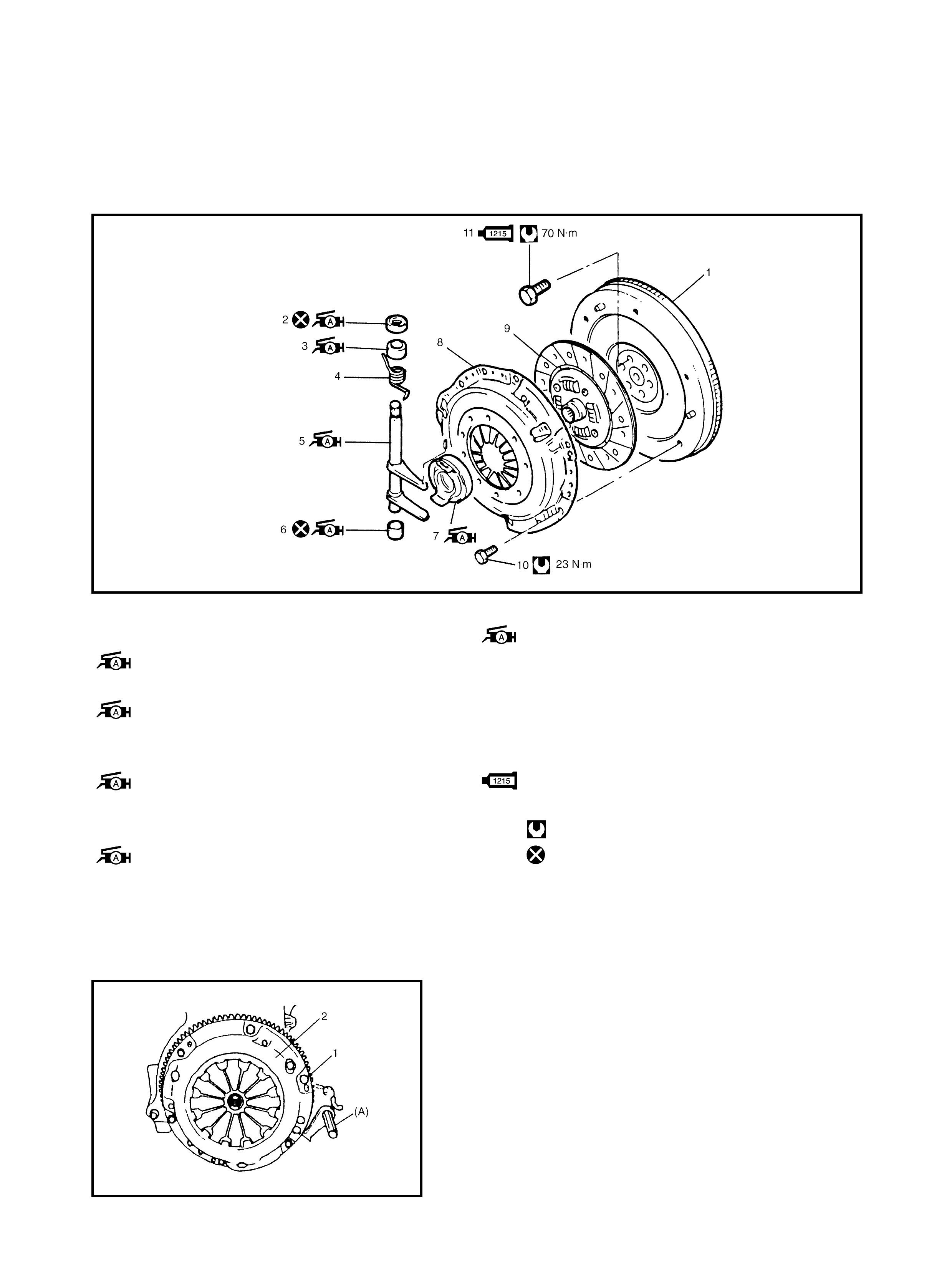
Legend
1. Crankshaft 5. Clutch cover 9. Input shaft
2. Flywheel 6. Diaphragm spr ing 10. Release shaft
3. Clutch disc 7. Release bearing
4. Pressure plate 8. Input shaft bearing

2. DIAGNOSIS
Condition Possible Cause Correction
Slipping Incorrect clutch pedal free travel Adjust free travel.
Worn or oily clutch disc facing Replace disc.
Wa rped disc, pressure plate or flywheel surface Re place disc, clutch cover o r
flywheel.
Weakened diaphragm spring Replace clutch cov er.
Rusted clutch cable Replace cable.
Dragging clutch Incorrect clutch pedal free travel Adjust free tra vel.
Weakened diaphragm spring, or worn spring tip Replace clutch cover.
Rusted input shaft splines Lubricate.
Damaged or worn splin es of tra nsaxle input shaft Re place input shaft.
Wa rped c lutch disc Replace disc .
Clutch fac ings broken or dirty with oil Re place disc.
Clutch vibration Glazed (glass-like) clutch fa cings Repair or replace disc.
Clutch fac ings dirty with oil Re place disc.
Release bearing binds on input shaft bearing
retainer Lubri ca te or replace input
shaft bearing retainer.
Wa rped c lutch disc, or poor facing contact Re place disc.
Weakened torsion springs in clutch disc Replace disc.
Clutch d isc rivets loose Replace disc.
Distor ted pres sure plate or flywheel surfac e Re place clutch cover or f ly-
wheel.
Weakened engine m ount or loose engine mou nting
bolt or nut Retighten or replace mount.
Noisy clutch Worn or broken release bearing Replace release bearing.
Input shaft front bearing worn Replace input sh aft beari ng.
Excessive rattle of clutch disc hub Replace disc .
Cracked clutch disc Replace disc.
Pressure plate and diaphragm sprin g rattling Replace c lutch cover.
Grabbing clutch Clutch disc facings soaked with oil Replace disc.
Clutch disc f a cings excessively worn Replace disc.
Riv et heads standing out from f acing Replace disc.
Weakened torsion springs Replace disc .
3. ON-VEHICLE SERVICE
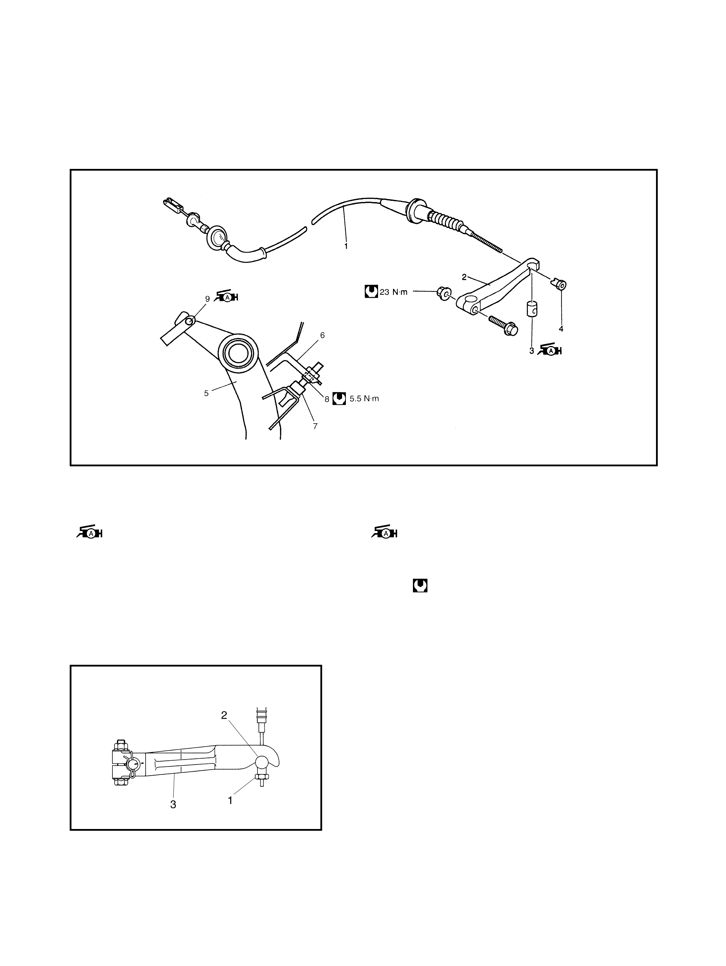
3.1 CLUTCH CABLE
Legend
REMOVAL
1. Disconnect the negative cable at battery.
2. Remov e the clutch cab l e joint nut (1).
3. Remove the joint pin (2) fr om the clutch release
lever (3).
1. Clutch cable 7. Adj usting bolt
2. Release leve r 8. Lock nut
3. Joint pin
: Apply Lithium grease to joint pin. 9. Clutch cable hook
: Apply Lithium grease to cable
hook.
4. Joint nut
5. Clutch pedal Tighteni ng torque
6. Pedal bracket

4. Disconnect the cab le hook (1) from the clutch
pedal (4).
5. Remove the clutch cable (3) from the bracket (5) by
tur ning the cable cap (2 ) about 90° as shown.
INSPECTION
Inspect the clutch cable and replace it i f any of the following
conditions exist:
• Excess ive cable frict i on
• Frayed cable
• Bent or kinked cable
• Broken boots
• Worn end
INSTALLATION
1. Apply grease to the cable end hook and joint pin before
installing cable.
(A): Lithium grease
2. From inside the cabin, hook the cable end onto the
pedal busing a screwdrive r or long nose pliers.
3. Join the inner cable wire joint pin in the release lever.
4. Install the clutch cable (2) to the b racket (3 ) by tur ning
the cable cap (1) about 90° as shown.
5. Screw in the joint nut and adjust the free travel of the
pedal to specification by turnin g nut.
6. Check the clutch for proper function with the engine
running.
NOTE: Ensure that the cable grommet (4) is installed in
the correct orientation as shown.
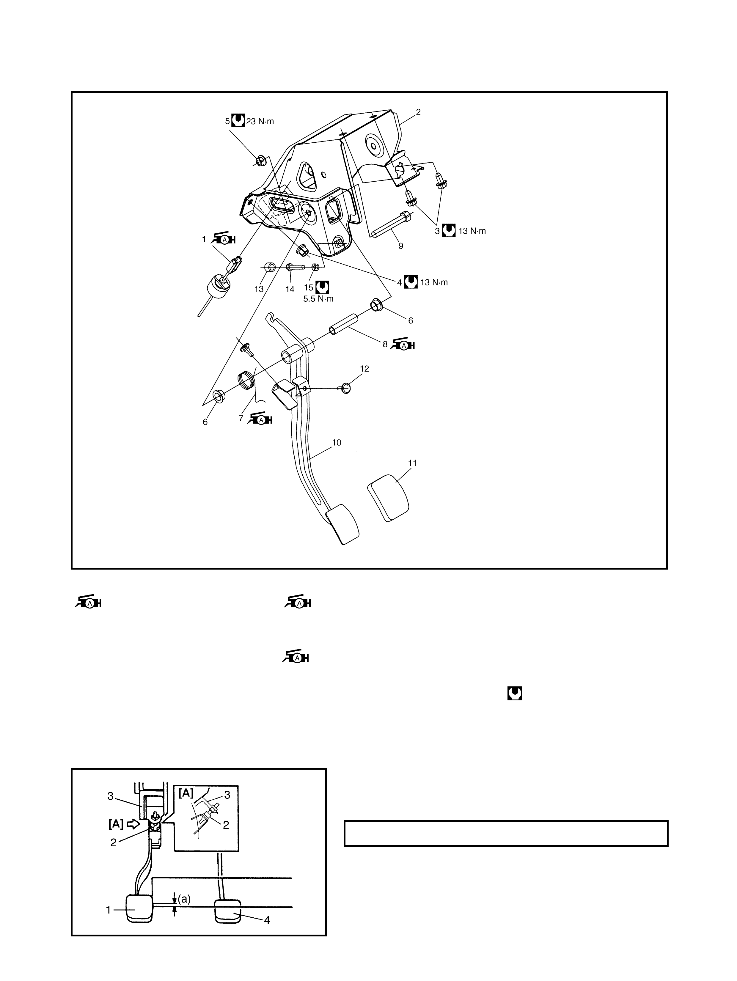
3.2 CLUTCH PEDAL AND CLUTCH PEDAL BRACKET
Legend
CLUTCH PEDAL HEIGHT
Adj ust the clu tch ped al (1) he ight with t he adj usting bolt (2)
located on the pedal bracket (3) so that the clutch pedal
height is same as the brake pedal (4) height.
1. Clut ch cable hook
: Apply Lithium grease to
cable hook.
7. Pedal spring
: Apply Lithium grease to
inside of spring.
11. Pedal pad
12. Pedal retu rn cushion
13. Adjusting bolt cap
2. Clutch pedal bracket 8. Pedal shaft spacer
: Apply Lithium grease to
outside of spacer.
14. Adjusting bolt
3. Bolt 15. L ock nut
4. Nut Tightening torque
5. Pedal shaf t nut 9. Pedal shaft
6. Pedal bush 10. Clutch pedal
HEIGHT DIFFERENCE (a) 0 mm
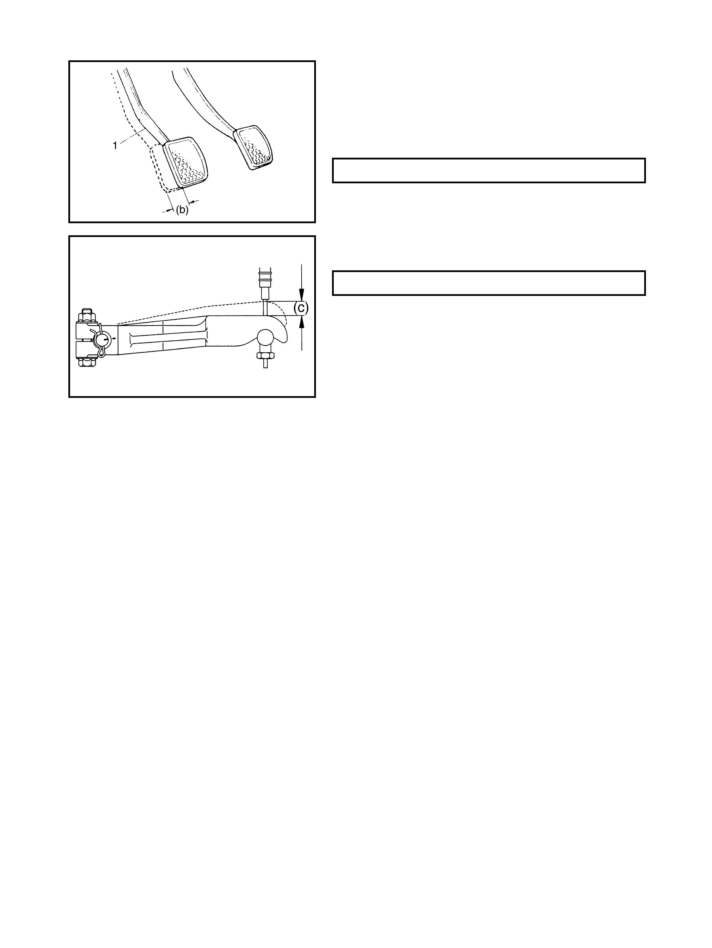
CLUTCH PEDAL FREE TRAVEL
1. Confir m that t he cl utch pedal heig ht is wi thin spec ifica-
tion.
2. Depress the clutch pedal (1), stop the moment clutch
resistance is felt and measure the distance (clutch
pedal free travel).
Free travel should be within th e following specification.
3. If the free travel is out of specificat ion, adjust it with the
cable joint nut (1).
4. After checking clutch pedal free travel, also check the
clutch f or correct function with the engine running.
PEDAL FREE TRAVEL (b) 15 - 20 mm
RELEASE LEVER FREE TRAVEL (c) 0 - 2 mm
4. UNIT REPAIR OVERHAUL
4.1 CLUTCH COVER, CLUTCH DISC AND FLYWHEEL
Legend
REMOVAL
1. Remove the transaxle assembly, refer to Section 7A,
MANUAL TRANSAXLE.
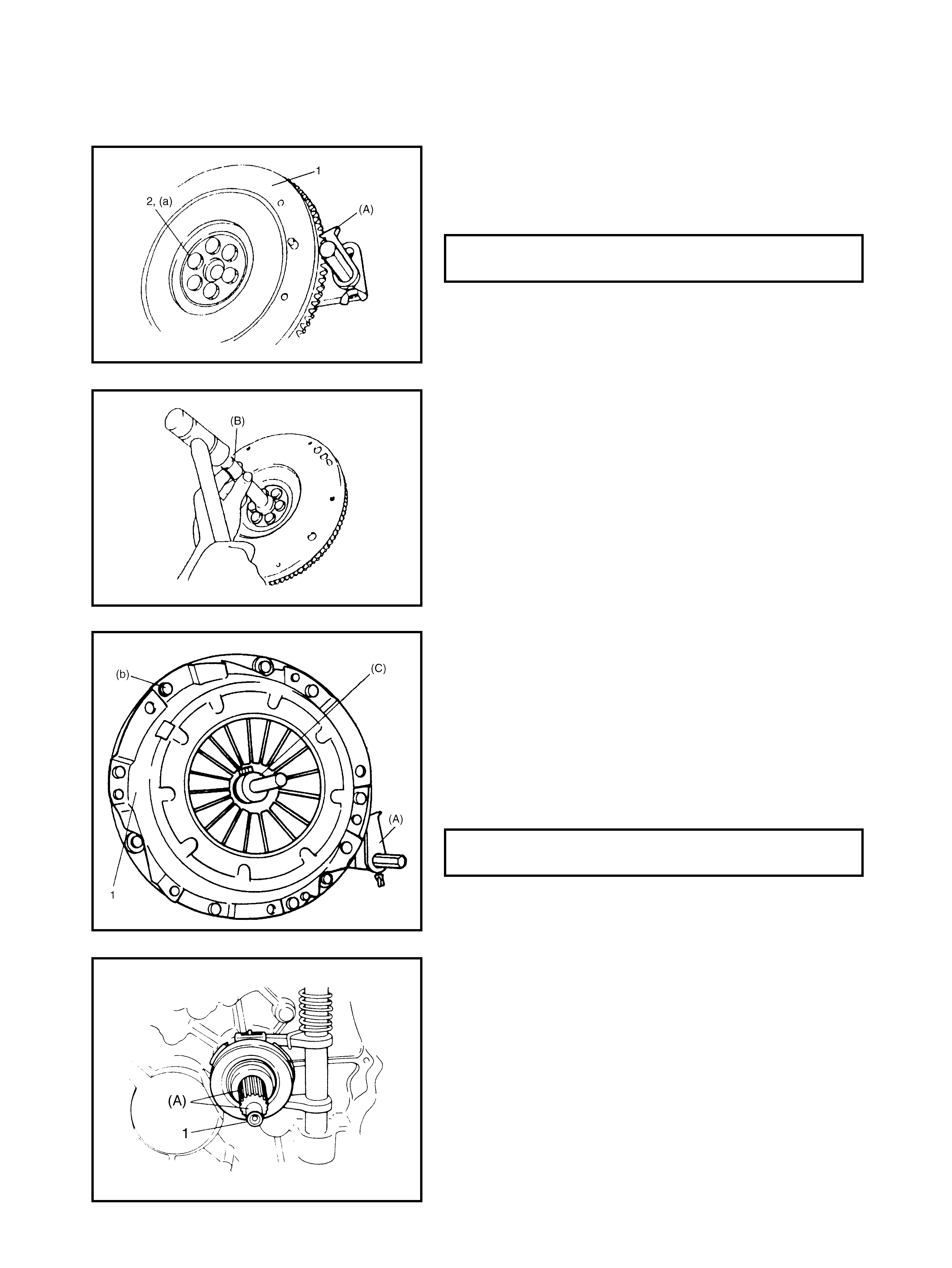
2. Hold the flywheel stationary with special tool 09924-
17811 (A) and remove the clutch cover bolts (1), clutch
cover (2) and clutch disc.
1. Flywheel 7. Release bearing
2. Clutch release shaft seal
: Apply Lithium grease to seal lip. : Apply Lithium grease to bear ing
joint, release shaft and inside bearing .
3. Clutch release shaft No.2 bush
: Apply Lithium grease inside bush. 8. Clutch cover
9. Clutch disc
4. Return spring 10. Clutch cov er bolt
5. Clutch release shaft
Apply Lithium grease to the end of
release shaft arm.
11. Flywheel bolt: Apply sealant Three Bond
No. 1215 to thread.
Tightening torque
6. C lutch release shaft No.1 bush
: Apply Lithium grease inside bush. Do not reuse.

3. Withdraw the input shaft bea ring (1) using special tool
09921-26020 (B), and a wrench.
INSPECTION
Input Shaft Bearing
Check the bearing (1) for smooth rotation. Replace it if
abnormality is f ound.
Clutch Disc
Measure the depth of the rivet head depression, i.e. dis-
tance between rivet head and facing surface.
If depth is fou nd to have reached ser vice limit at any hole,
replace the disc asse mbly.
Clutch Cover
1. Check the diaphragm spring (1) for abnormal wear or
damage.
2. Inspect the pressure plate (2) for wear or heat spots.
3. If abnormality is found, replace it as an assembly. Do
not disassem ble it.
Flywheel
Check the surface contacting the clutch disc for abnormal
wear or heat spots. Replace or repair as required.
RIVET HEAT DEPTH: STANDARD
SERVICE LIMIT 1.65 - 2.25 mm
0.5 mm
INSTALLATION
NOTE: Before assembling, ensure that the flywheel sur-
face and pressure plate surface have been cleaned and
dried thoroughly.
1. Install the flywheel (1) to the crankshaft using special
tool 09924-17811 (A).
2. Apply sealant Three Bond No. 1215 to the bolts (2) and
tighten to specification.
3. Using special tool 09925-98210 (B), install the input
shaft bearing to the flywheel.
4. Align the clutch disc to the flywheel centre using
special tool 09923-36320 (C).
5. Install the clutch cover (1) and bolts. Then tighten bolts
to specification.
NOTE 1: While tightening the clutch cover bolts,
depress the clutch disc using the special tool (C) by
hand to ensure the disc remains centred.
NOTE 2: Tighten the cover bolts in small amounts
evenly, in diagonal order.
6. Apply a small amount of grease to the input shaft (1).
(A): Lithium grease
7. Install the transaxle assembly onto the engine. Refer to
Section 7A, MANUAL TRANSAXLE.
NOTE: Wh en ins erting the transaxl e inpu t sh aft onto
the clutch disc, rotate the crankshaft to align the
splines.
FLYWHEEL BOLT (a)
TORQUE SPECIFICATION 70 Nm
CLUTCH CO VER BOLT TORQUE
SPECIFICATION (b) 23 Nm
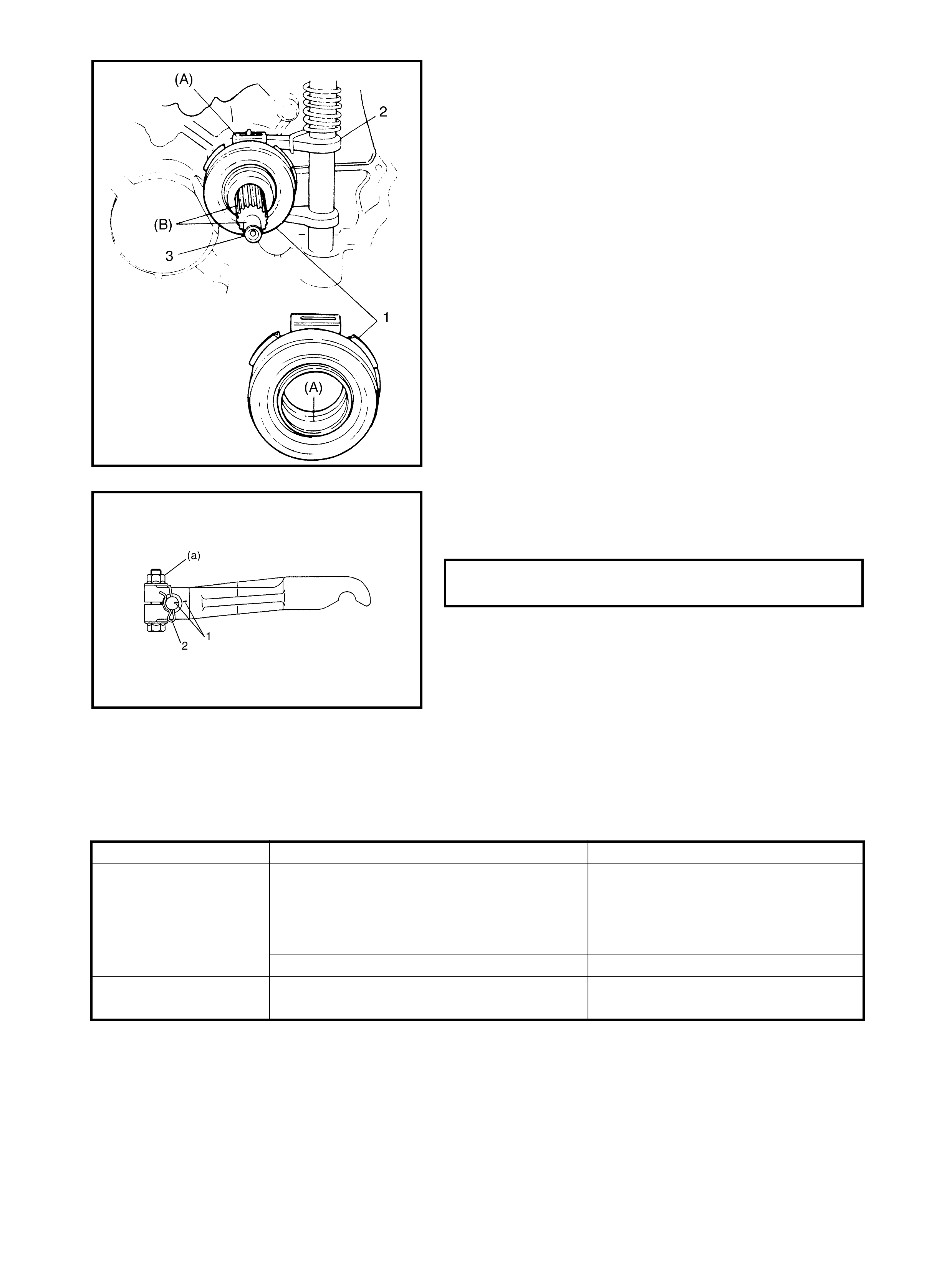
4.2 CLUTCH RELEASE SYSTEM
REMOVAL
1. Remove the release lever by loo se ning its bolt.
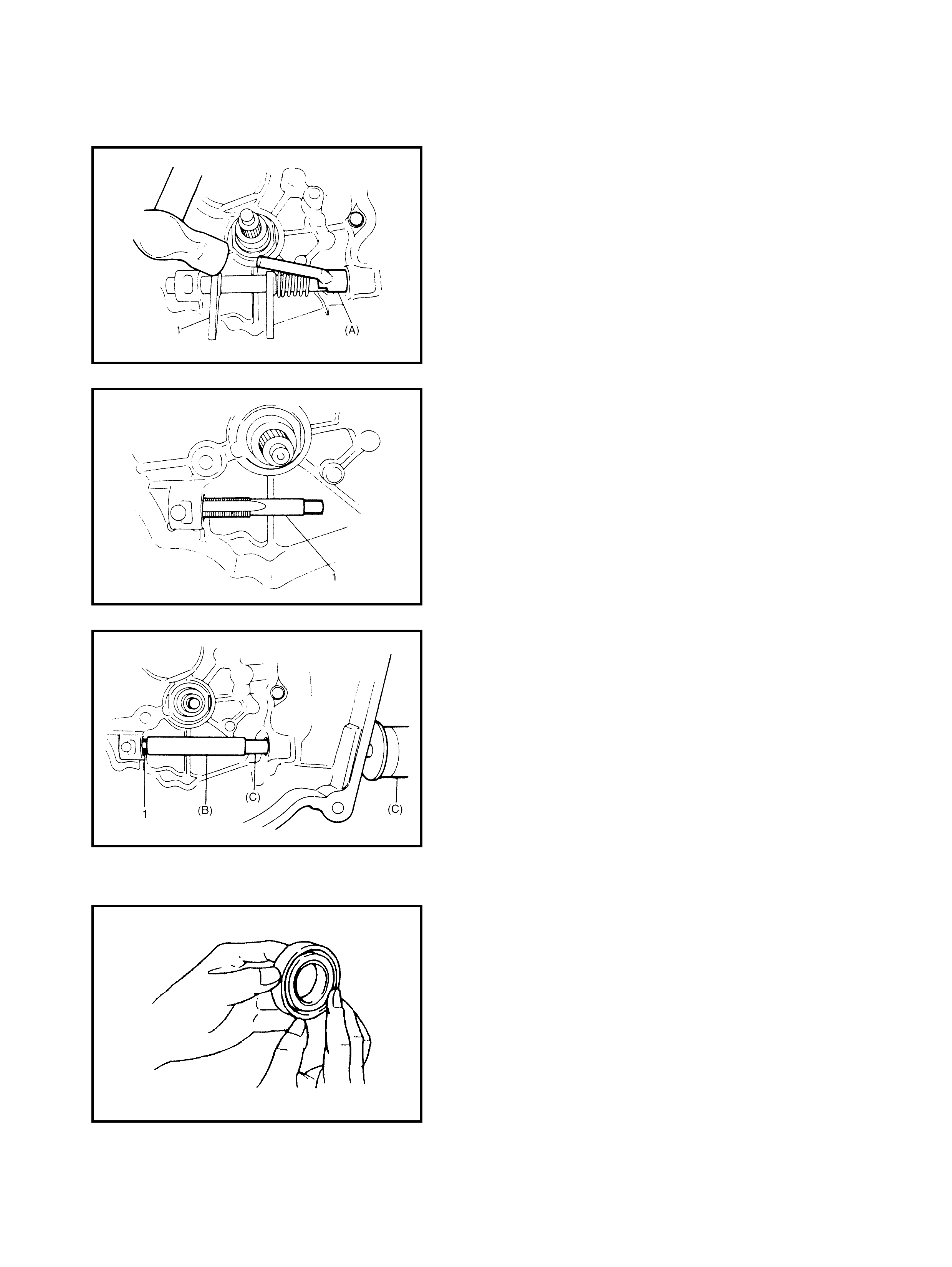
2. Remove the release bearing by turning the release
shaft (1).
3. Unhook the return spring by using pliers.
4. Drive out the No.2 bush by using special tool 09922-
46010 (A) and a hammer.
The re lease sh aft seal w ill also be pus hed out .
5. Remove the release shaft and return spri ng.
6. Insert a tap (M16 X 1.5) (1) into t he clutch release shaft
No.1 bush.
7. Withdraw the No.1 bush by using the tap (1) and
specia l tools 09923-46020 (B) and 09930-30104 (C).
INSPECTION
Clutch Release Bearing
Check the clutch release bearing for smooth rotation.
If abnormal ity is found , replace the beari ng.
CAUTION: Do not wash the release bearing. Washing
may cause grease leakage and consequential bear-
ing damage.
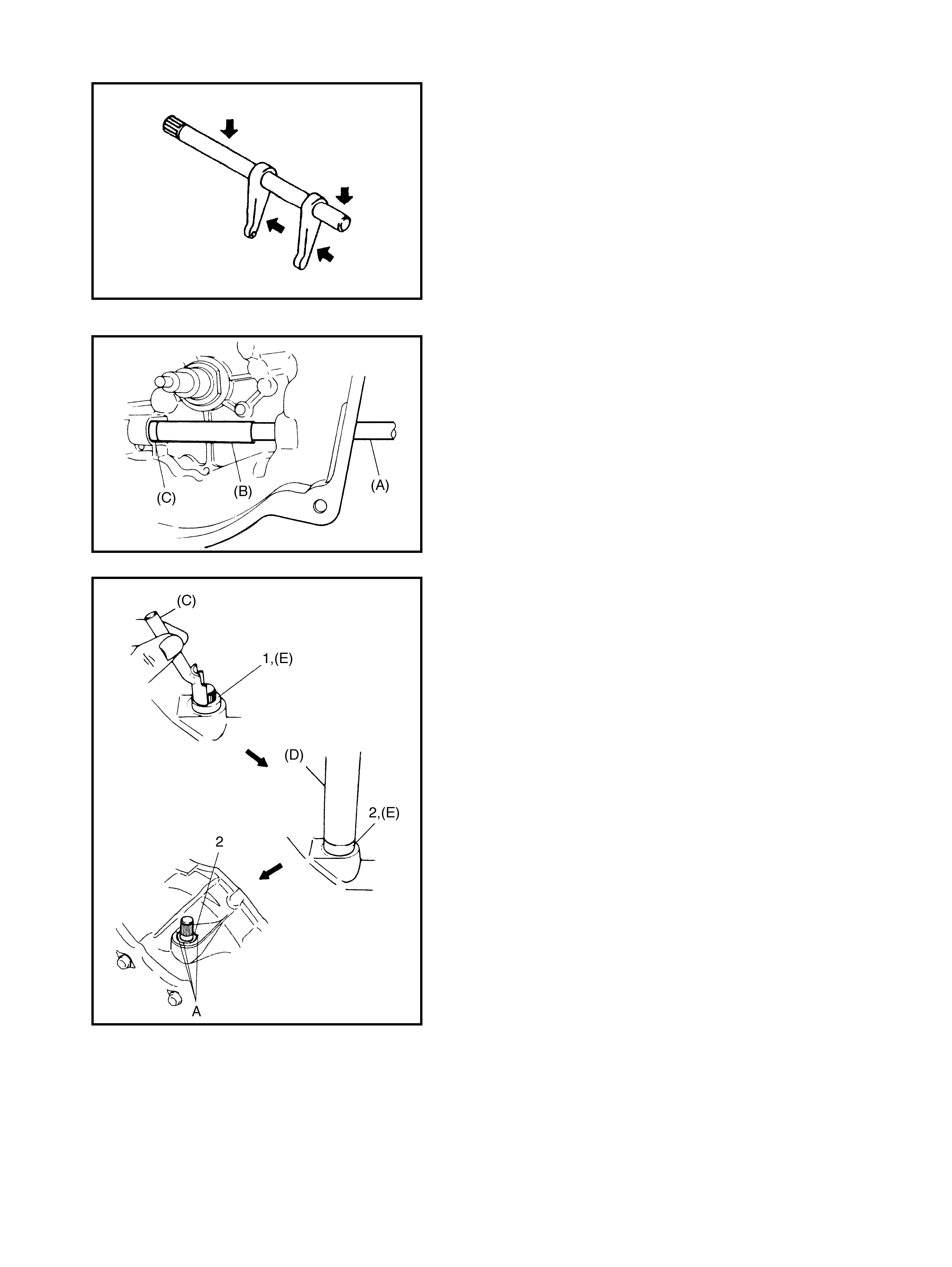
Clutch Release Shaft
Check the clutch release shaft a nd its pin for deflection or
damage.
If abnormal ity is found, replace it.
INSTALLATION
1. Drive in a new No.1 bush using special tools 09930-
30104 (A) and 09923-46 030 (B).
2. Appl y grease inside the bush.
(C): Lithium grease
3. Install the release shaft with the retur n spr ing fitted.
4. Apply grease inside No.2 bush (1) and press-fit it by
using the special tool 09922-46 010 (C ).
5. Appl y grease to the shaft seal (2) lip.
6. Use special tool 09925-98221 (D) to install the seal,
ensuring the face (lip) is downward (to ward the inside).
(E): Lithium grease
7. Stake the seal at A by using a staking tool and
hammer.
8. Hook the return s pring.
9. Apply grease inside the release bearing (1) and the
release shaft arm (2), then set the bearing.
(A): Lithium grease
10. Apply a small amount of grease to the input shaft (3)
spline and front end.
(B): Lithium grease
11. Set th e release leve r to the release s haft , alignin g their
punch marks (1).
12. Tighten the nut to the specified torque.
13. Install the clip (2) onto the clutch release shaft.
5. REQUIRED SERVICE MATERIAL
RELEASE LEVER BOLT TORQUE
SPECIFICATION (a) 23 Nm
Material Recommended product Use
Lithium grease Lithium grease •Cable end hook and joint pin.
•Release shaft bushes and s eal.
•Re lease shaft arm.
•Release bearing inside.
Lithium grease Input shaft spl ine and front end.
Sea lant Three Bond No. 1215 Flywheel bolt thread.
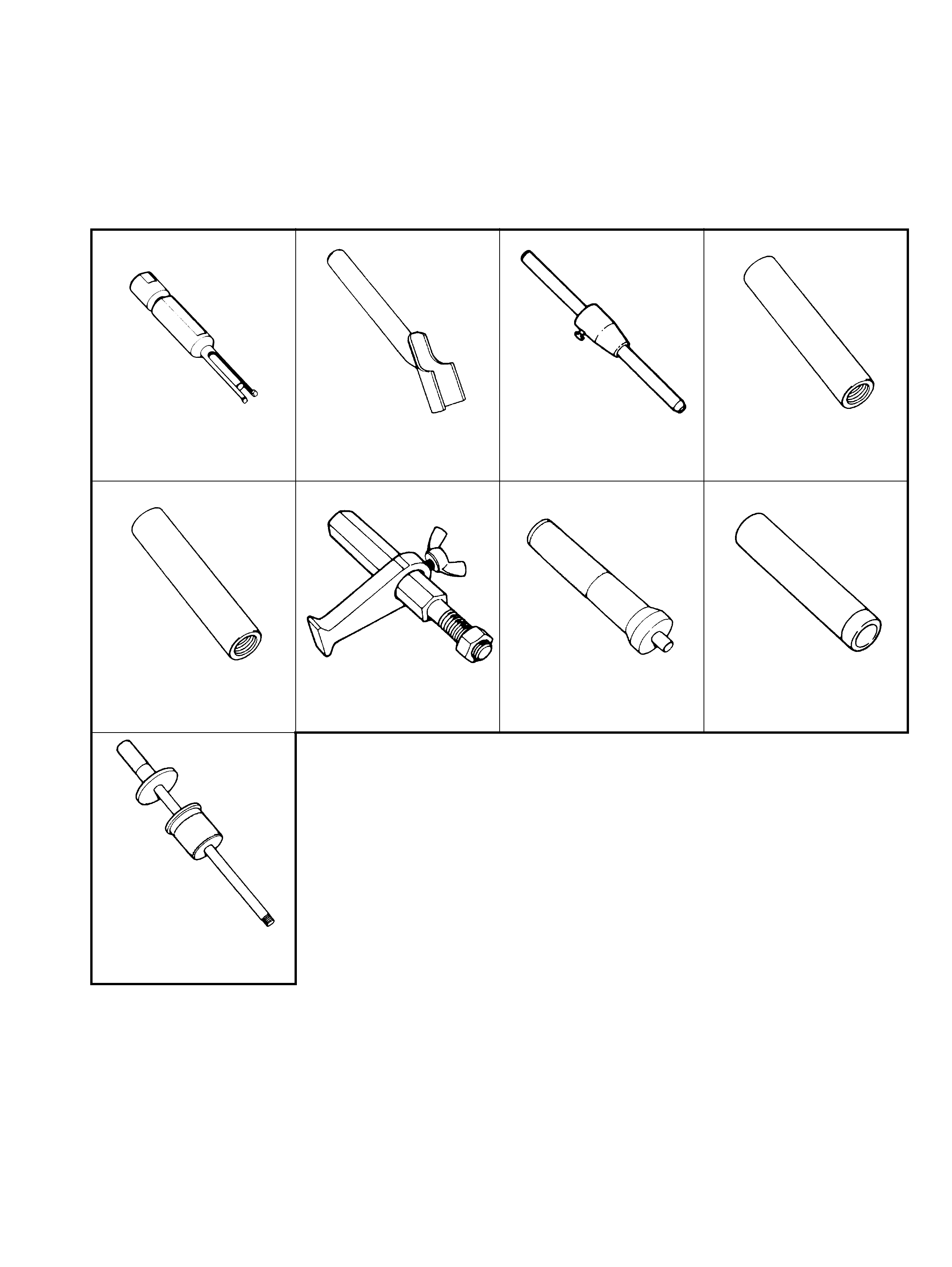
6. SPECIAL TOOLS
NOTE: Refer to Section 0A GENERAL INFORMATION – 7. CONSOLIDATED TOOLS for a detailed list of
special tools and the local equivalent if one is available.
09921-26020 09922-46010 09923-36320 09923-46020
Bearing remov er Bush remover Clutch centre guide Joint pipe
09923-46030 09924-17811 09925-98210 09925-98221
Joint pip e Flywheel hold er Input shaft bearing insta ller Bear ing inst aller
09930-30104
Sl iding shaft