
SECTION 7D - TRANSFER
1. GENERAL DESCRIPTION
2. DIAGNOSIS
2.1 DIAGNOSIS TABLE
3. ON-VEHICLE SERVICE
3.1 OIL CHANGE
4. TRANSFER UNIT OVERHAUL AND REPAIR
4.1 TRANSFER UNIT
Removal
4.2 TRANSFER UNIT DISASSEMBLY
Transfer Assembly
Reduction Driven Gear Assembly
Intermediate Shaft
Transfer Output Retainer Assembly
4.3 COMPONENT INSPECTION
4.4 TRANSFER UNIT ASSEMBLY
Reduction Driven Gear Assembly
Bevel Gear Shim Adjustment
Transfer Output Retainer Assembly
Right Case
Left Case
Transfer Assembly
4.5 BEVEL GEAR BACK LASH
Measurement
Gear Tooth Contact
4.6 TRANSFER UNIT
Installation
5. REQUIRED SERVICE MATERIAL
6. SPECIAL TOOLS
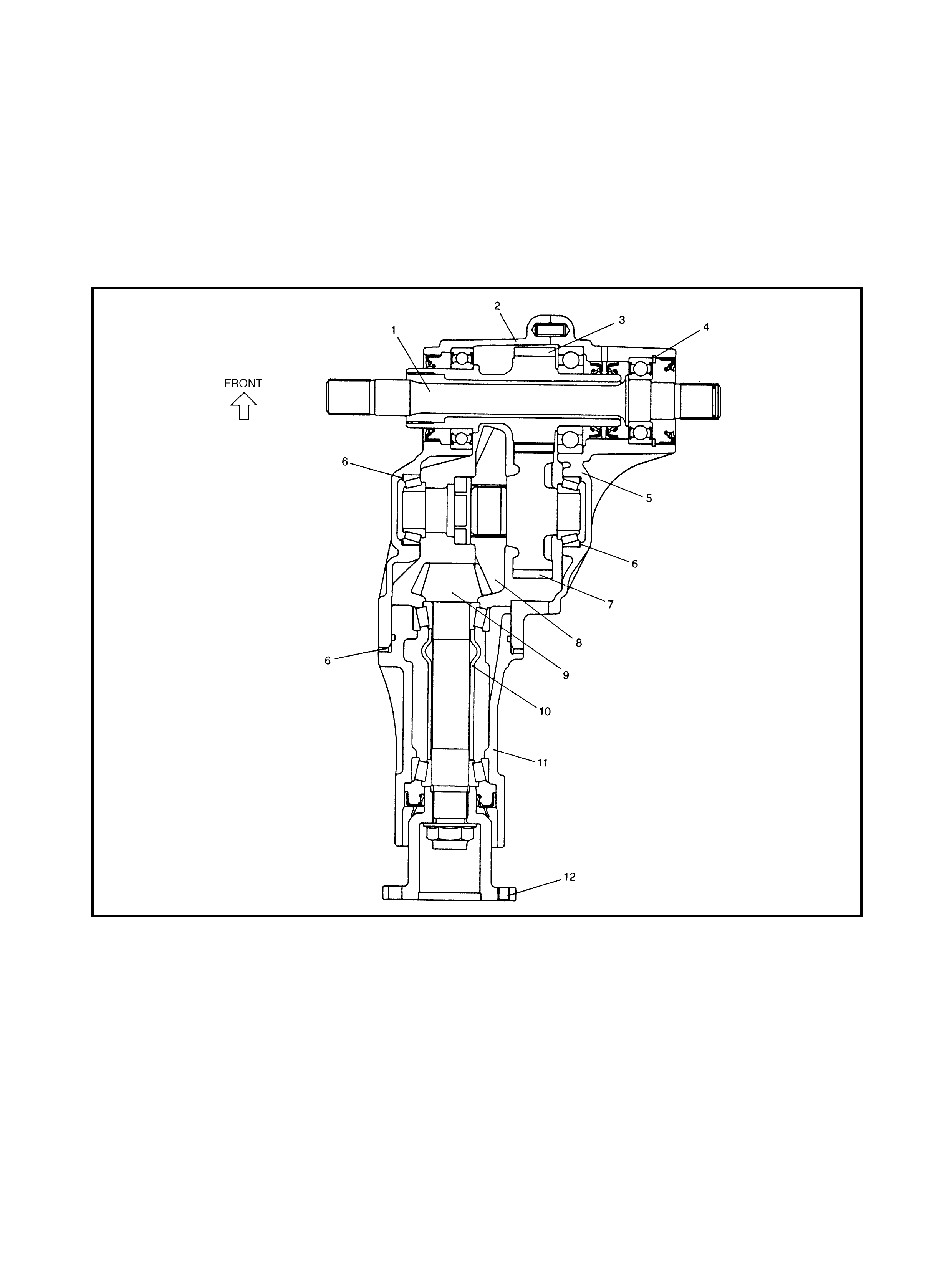
1. GENERAL DESCRIPTION
The transfer is mounted to the transaxle case (manual/automatic). The reduction drive gear (intermediate
shaft) in the transfer and the differential in the transaxle are coup led by an involute spline. The dr iving force
from the transaxle is transmitted to the propeller shaft via the transfer reduction drive gear, reduction dr iven
gear and bevel gears. The bevel (hypoid) gears change the direction of the driving force 90°. Hypoid type
gears help prevent ge ar noise but require accurate adjustment of backlash and too th contac t.
Legend
1. Intermediate shaft 6. Shim 10. Pinion shaft spacer
2. Left case 7. Reduction driven gear 11. Transfer output retainer
3. Reduction dr ive g ear 8. Bevel gear (hyp oid gear) 12. Flange
4. Circlip 9. Bevel pinion shaft
5. Right case (hypoi d gear)
2. DIAGNOSIS
2.1 DIAGNOSIS TABLE
3. ON-VEHICLE SERVICE
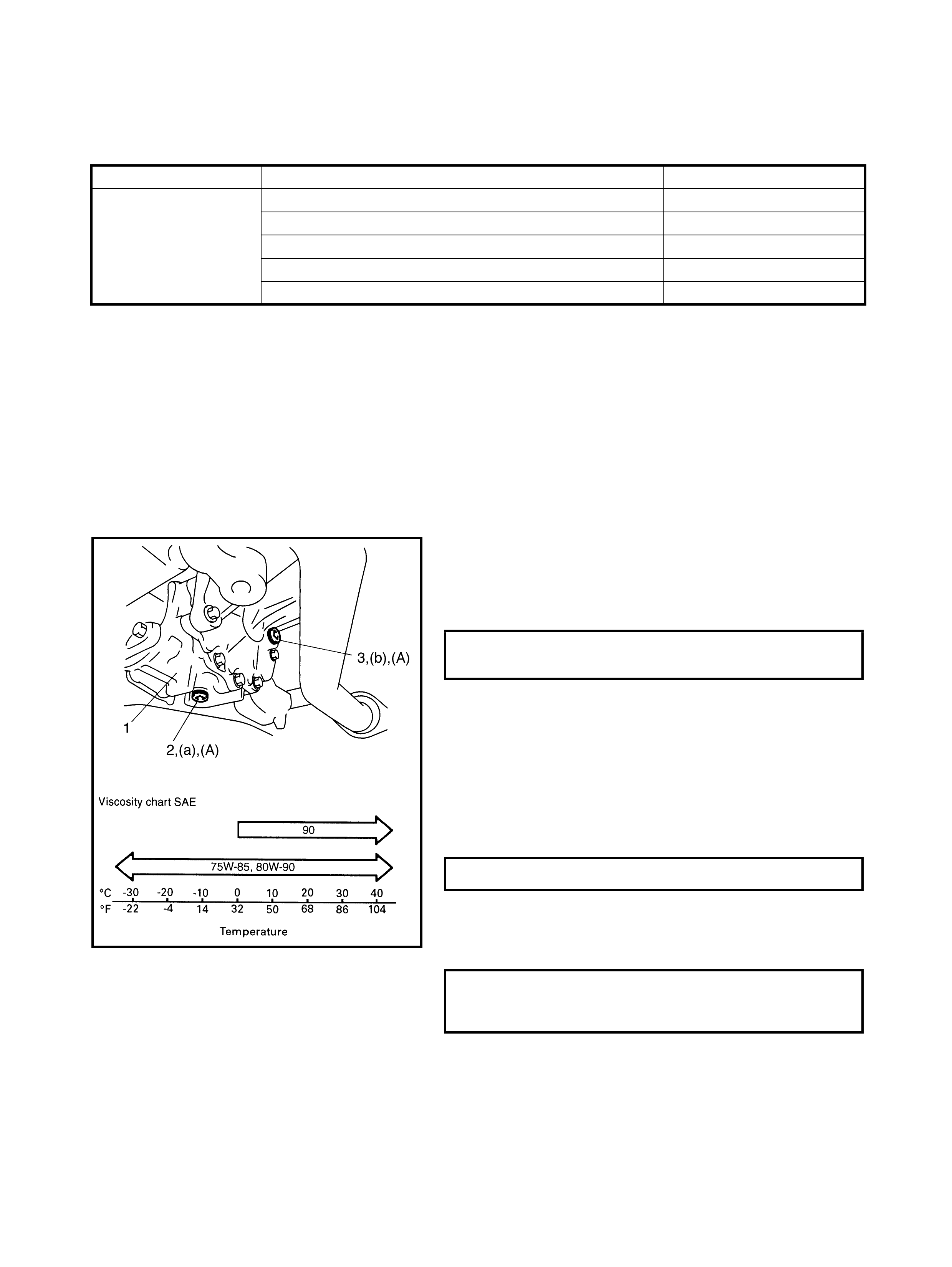
3.1 OIL CHANGE
1. Raise t he vehicl e on a h oist and ch eck th e transfer (1)
oil level. Look for signs of leakage and If leakage
exists, correct or rep air it.
2. Drain the existing oil, apply sealant to the drain plug
thread (2), refit and torque to specification. Fill the
transfer with the specifi ed oil (up to level chec k hole).
(A): Sealant - Three Bond No. 1216B
NOTE:
• It is highly recommended to use SAE 80W-90 Hypoid
gear oil API GL-5.
• Whenever the vehicle is raised on a hoist check fo r oil
leakage.
Transfer gear oil
: Hypoid gear oil API GL-5
For oil viscosity, refer to the chart in the figure .
3. Apply sea lant to the level/filler plug thread (3), refit a nd
torque to specification.
(A): Sealant - Three Bond No. 1216B
Condition Possible Cause Correction
Noise Inadequate or insufficient lubricant Replenish.
Damaged or worn bearing(s) Replace.
Damaged or worn gear(s) Replace.
Damaged or wor n chamfered tooth on sleeve or gear Replace.
Preload of taper roller bearing is r educed Adjust.
TRANSFER OIL DRAIN PLUG (a)
TORQUE SPECIFICATION 21 Nm
TRANSFER OIL CAPACITY 0.5 l it res
TRANSFER OIL LEVEL/FILLER
PLUG (b)
TORQUE SPECIFICATION 21 Nm
4. TRANSFER UNIT OVERHAUL AND REPAIR
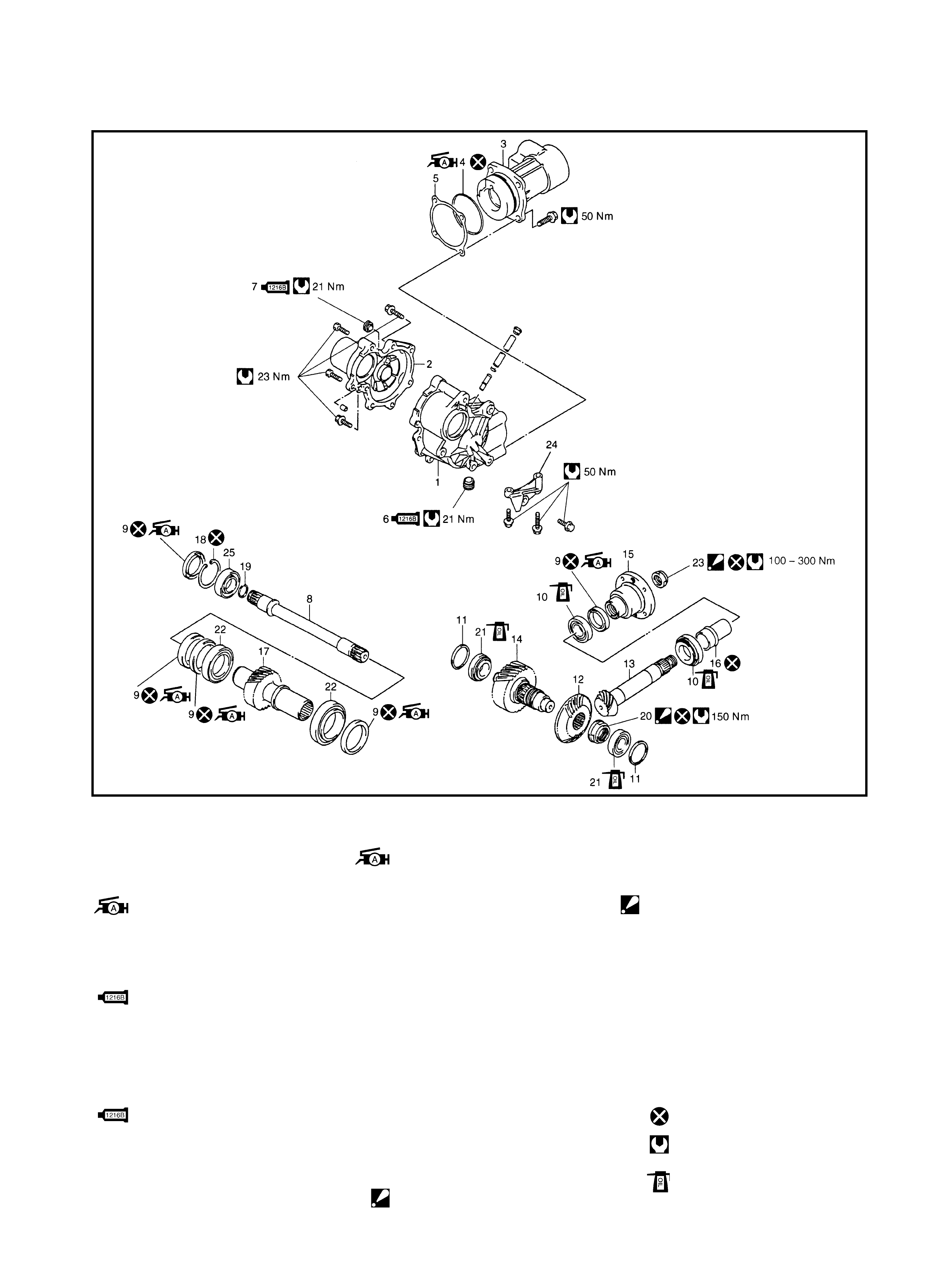
Legend
1. Transfer left case 8. Interm ediate sh aft 21. Drive n gear bearin g
2. Transfer right case 9. Oil seal
: Apply Lithium grease to
oil se al lip.
22. Reduction dr ive g ear
bearing
3. Transfer output retainer
4. O-ring
: Apply Lithium grease
all around surface.
23. Flange nut
: After tig htening nut and
rotation torque of bev el
pinion shaft is as
specified value, stake
nut securely.
10. Pinion shaft bear ing
11. Bevel gear shim
5. Bevel pinion shim 12. Bevel gear (Hypoid gear)
6. Drain plug
: Apply sealant Three
Bond No. 1216B all
around thread part of
drain plug
13. Bevel pin ion shaft
(Hypoid gear)
14. Reduction driven gear 24. Transfer stiffener
15. Flange 25. Interm edi ate shaft ri ght
bearing
16. Pinion shaft spacer
7. Level/fil ler plug
: Apply sealant Three
Bond No. 1216B all
around thread part of
level plug.
17. Reduction drive gear Do not reuse.
18. Circlip Tightening torque
19. Snap ring Apply transfer oil.
20. Bevel gear nut
: After tightening nut to
specified torque, caulk
nut securely.
4.1 TRANSFER UNIT
REMOVAL
1. Disconnect the negative battery cable .
2. Remove the transfer breather hose from the clamp on
the transaxle.
3. Hoist the vehicl e and remov e the wheels.
4. Drain the transaxle oil and transfer oil, refer to
3.1 OIL CHANGE in this Section.
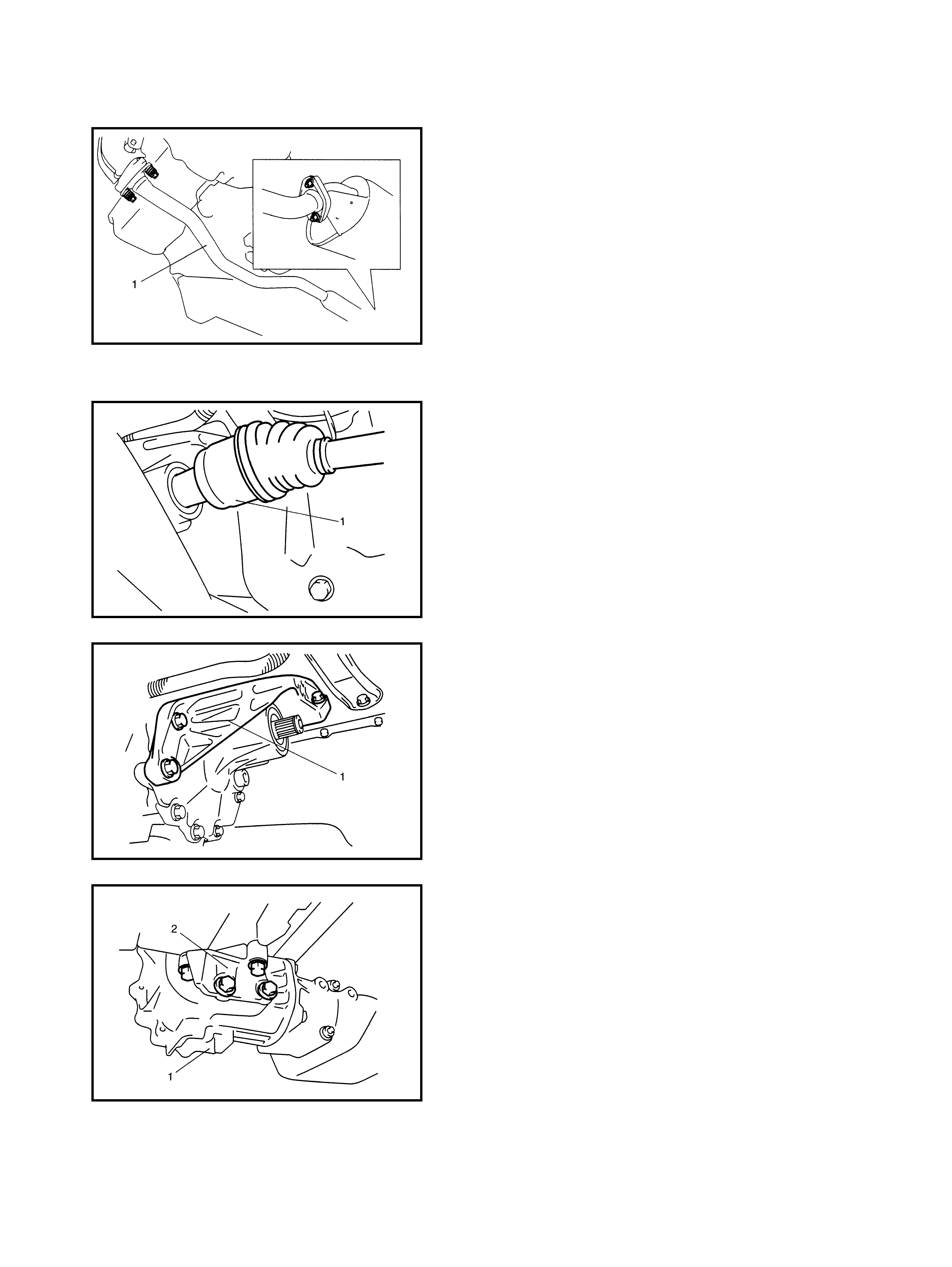
5. Remove the exhaust pipe (1), refer to Section 6K
EXHAUST SYSTEM.
6. Remove the propeller shaft, refer to Section 4B
PROPELLER SHAFTS.
7. Remove the right side drive shaft (1), refer to
Section 4A FRONT DRIVE SHAFTS.
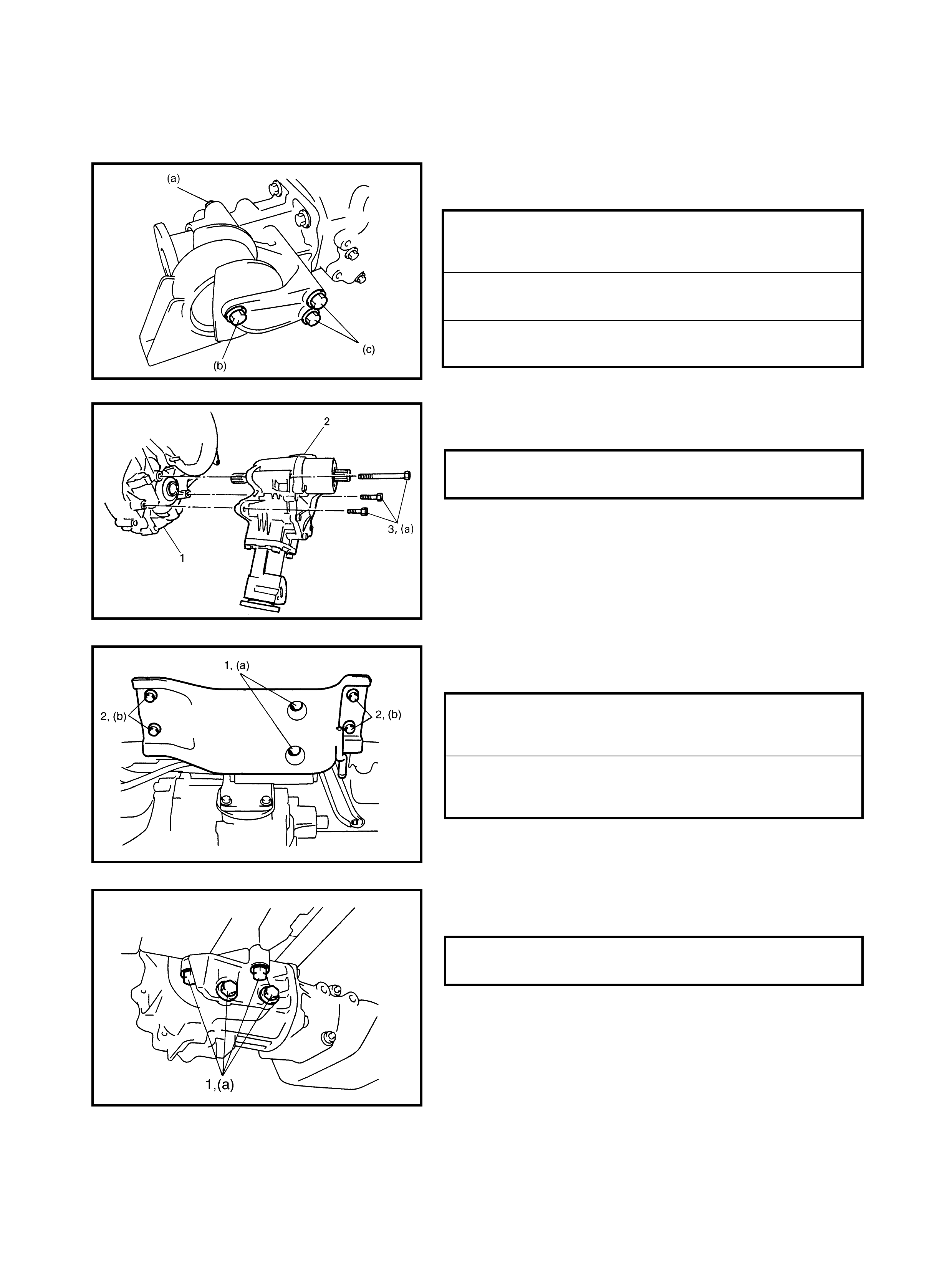
8. Remove the 5 bolts securing the transfer-to-engine
stiffener (1) and remove the stiff ener.
9. Remove the stiffener (2) from the transfer (1).
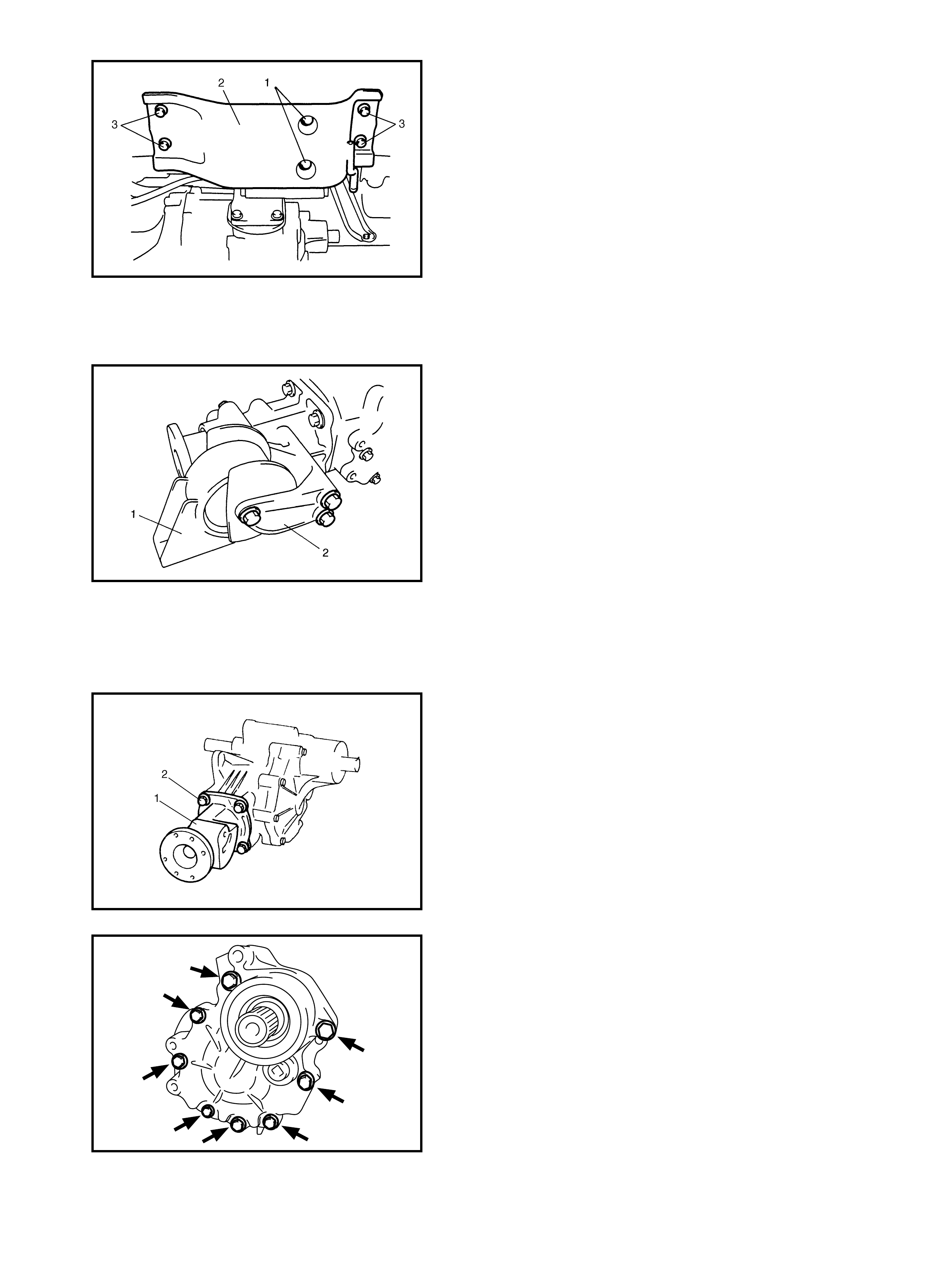
10. With the transaxle as sembly supported wi th a jack and
stand, remove the rear mounting bracket bolts (1).
11. Remove the bolts (3) securing the rear mounting
mem ber (2) and re move.
12. Remove the transfer to transaxle retaining bolts and
slide out the transfer assembly from the transaxle
assembly.
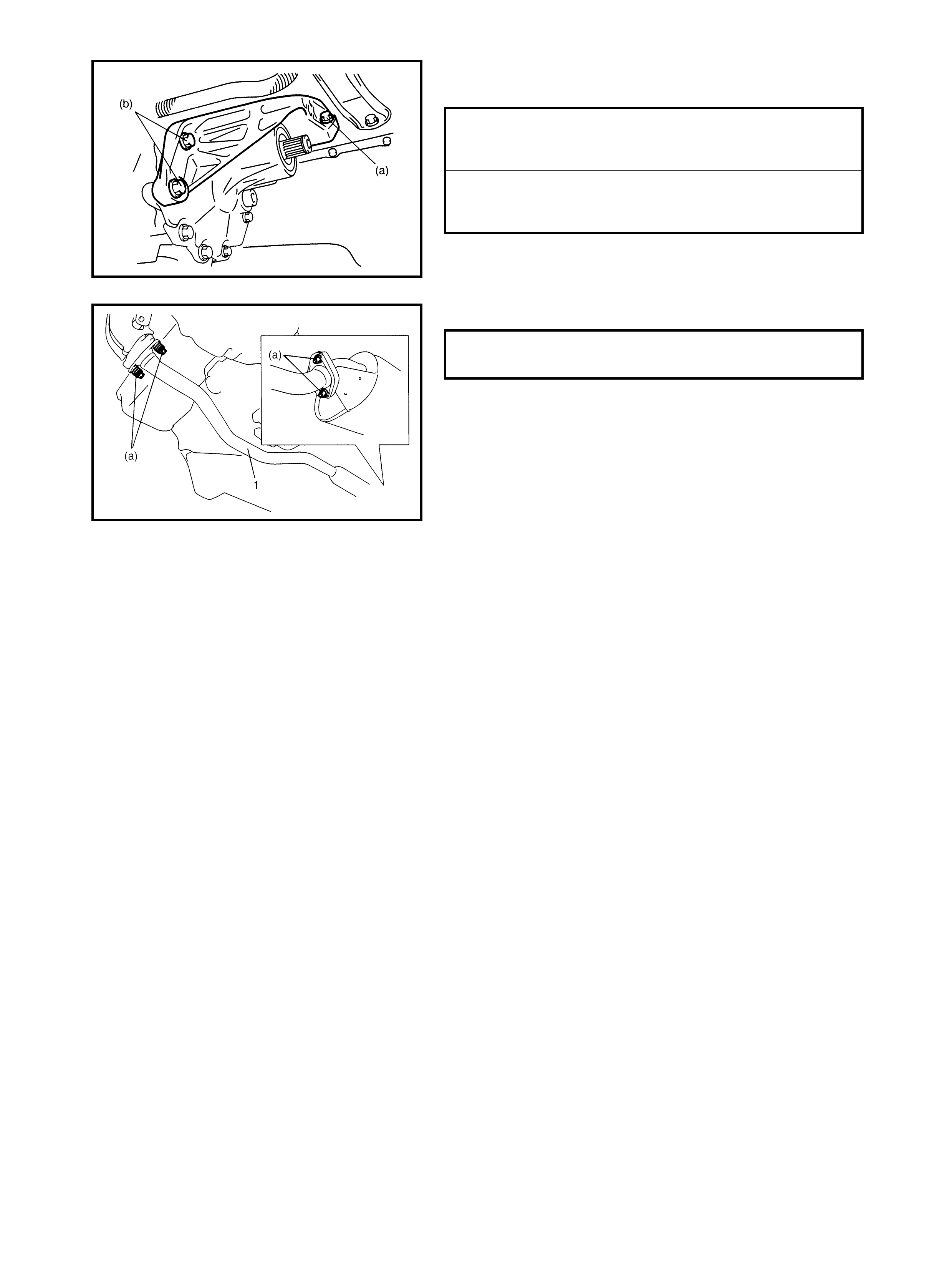
13. Remove the rear mounting (1) and rear mounting
bracket (2) from the transfer assembly.
14. Remove the breather hos e from the transfer assembly.
4.2 TRANSFER UNIT DISASSEMBLY
TRANSFER ASSEMBLY
1. Remove the retainer se curing bolts (2 ) and rem ove the
transfer output retainer assembly (1).
2. Remove the transfer case bolts.
3. Separate the right case (with the intermediate shaft)
from left case by tapping with a plastic hammer.
4. Remov e the reduction drive gear assembly (1) from the
left case by tapping with a plastic hamme r.
5. Remove the reduction drive gear bearings (2) (right
and l eft) from t he reduct ion dr ive g ear using a b earing
puller and hydraulic press.
REDUCTION DRIVEN GEAR ASSEMBLY
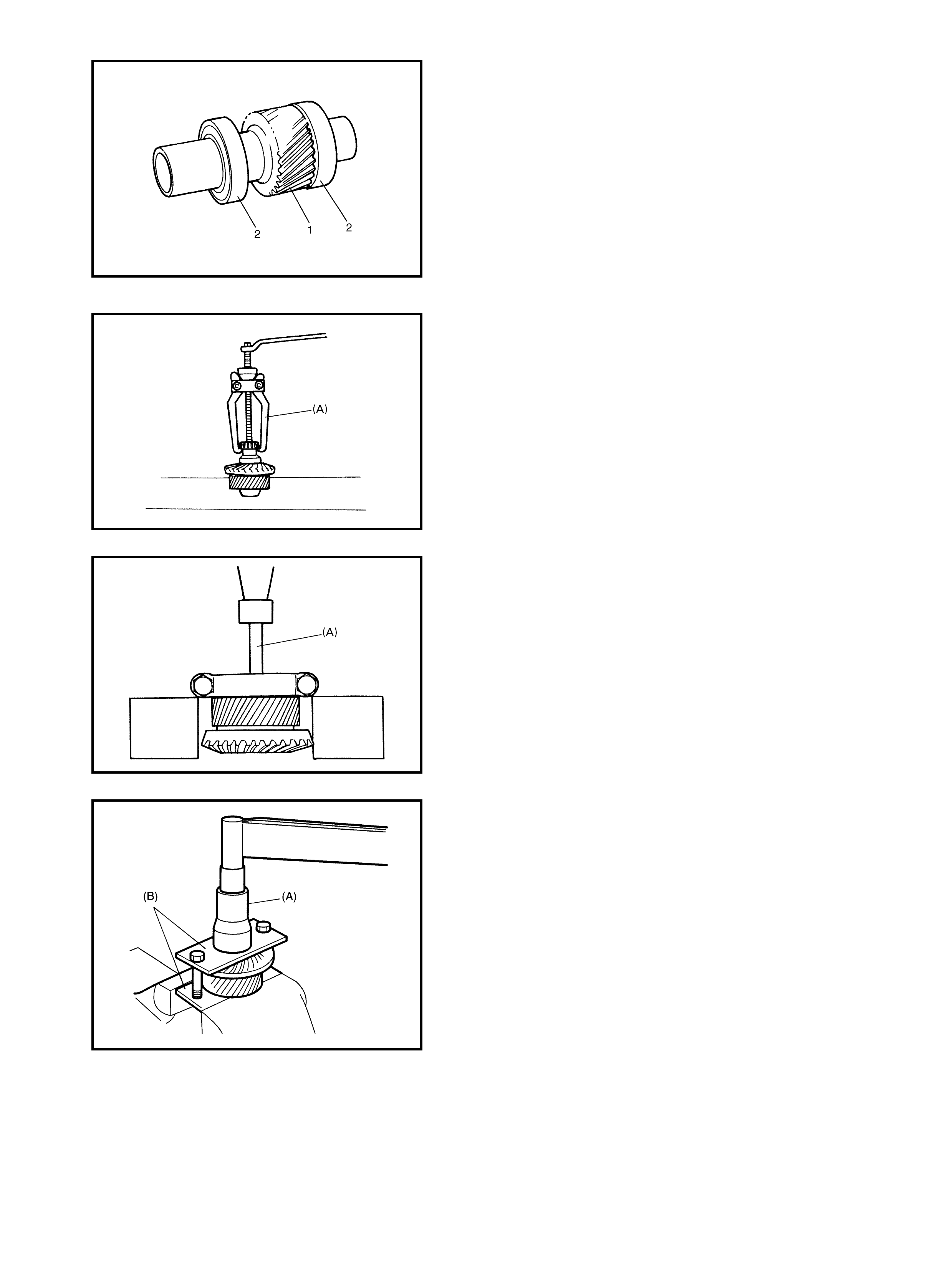
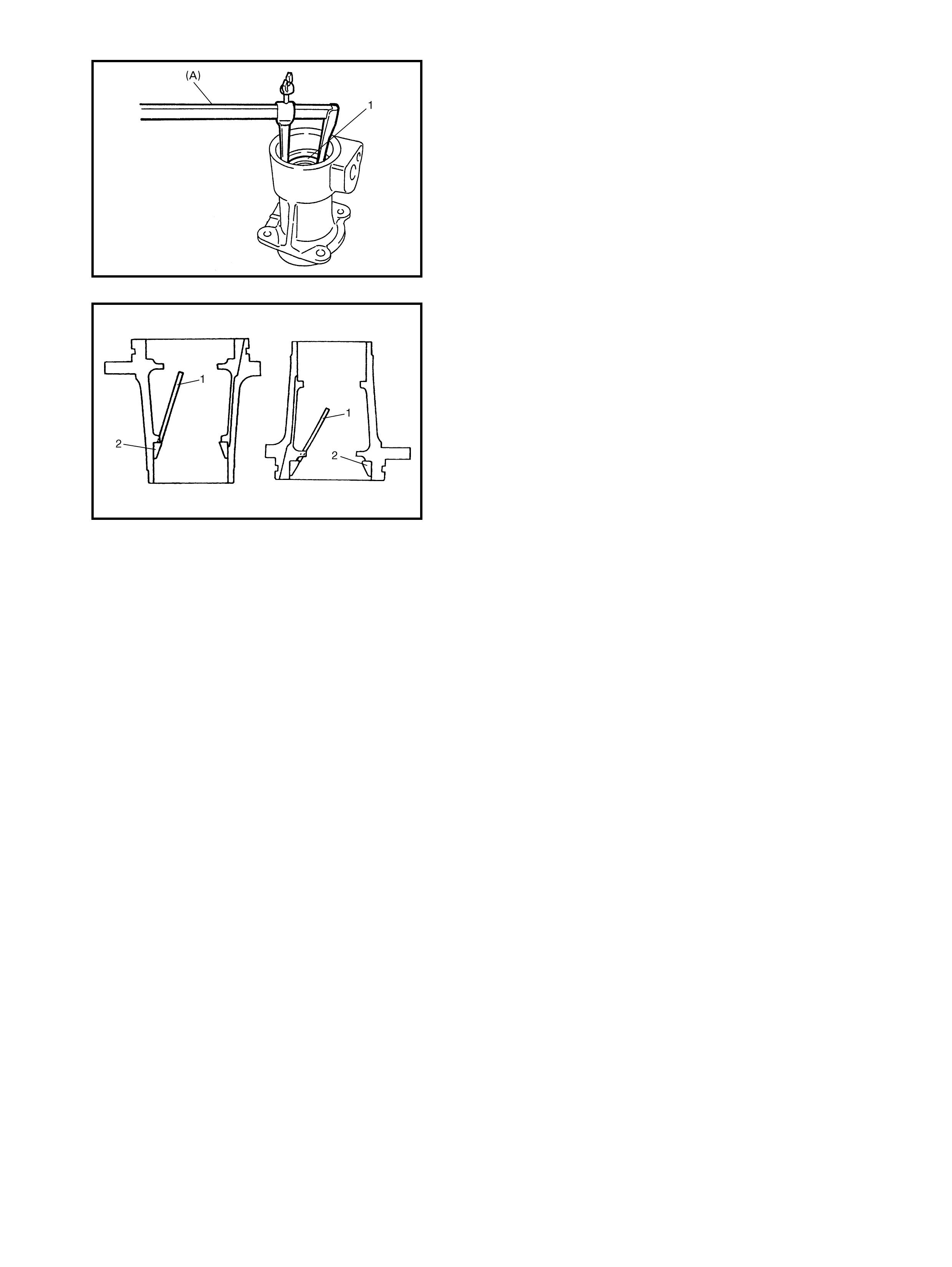
1. Drive out the left side driven gear bearing using special
tool 09913-65135 (A ).
2. Drive out the right side driven gear bearing using a
bearin g p uller, hydraulic press and special tool 09925-
58210 (A).
3. Unstake the bevel gear nut and remove while holding
the bevel gear with special tools 09941-58020 (A),
09924-57610 (B) and vise.
4. Drive out the bevel gear (1) using special tool 09913-
65135.
5. Remove the driven gear bearing outer race from the
left case (1) using special tool 09941-54911.
6. Remove the driven gear bearing outer race from the
right case (1) using spec ial tool 09941-54911 (A).
INTERMEDIATE SHAFT
1. Remove the reduction drive oil seal and snap ring,
then dri ve out the interm edia te shaft.
2. Drive out the intermediate shaft right bearing (1) from
the intermediate shaft using a bearing puller and
hydraulic press.
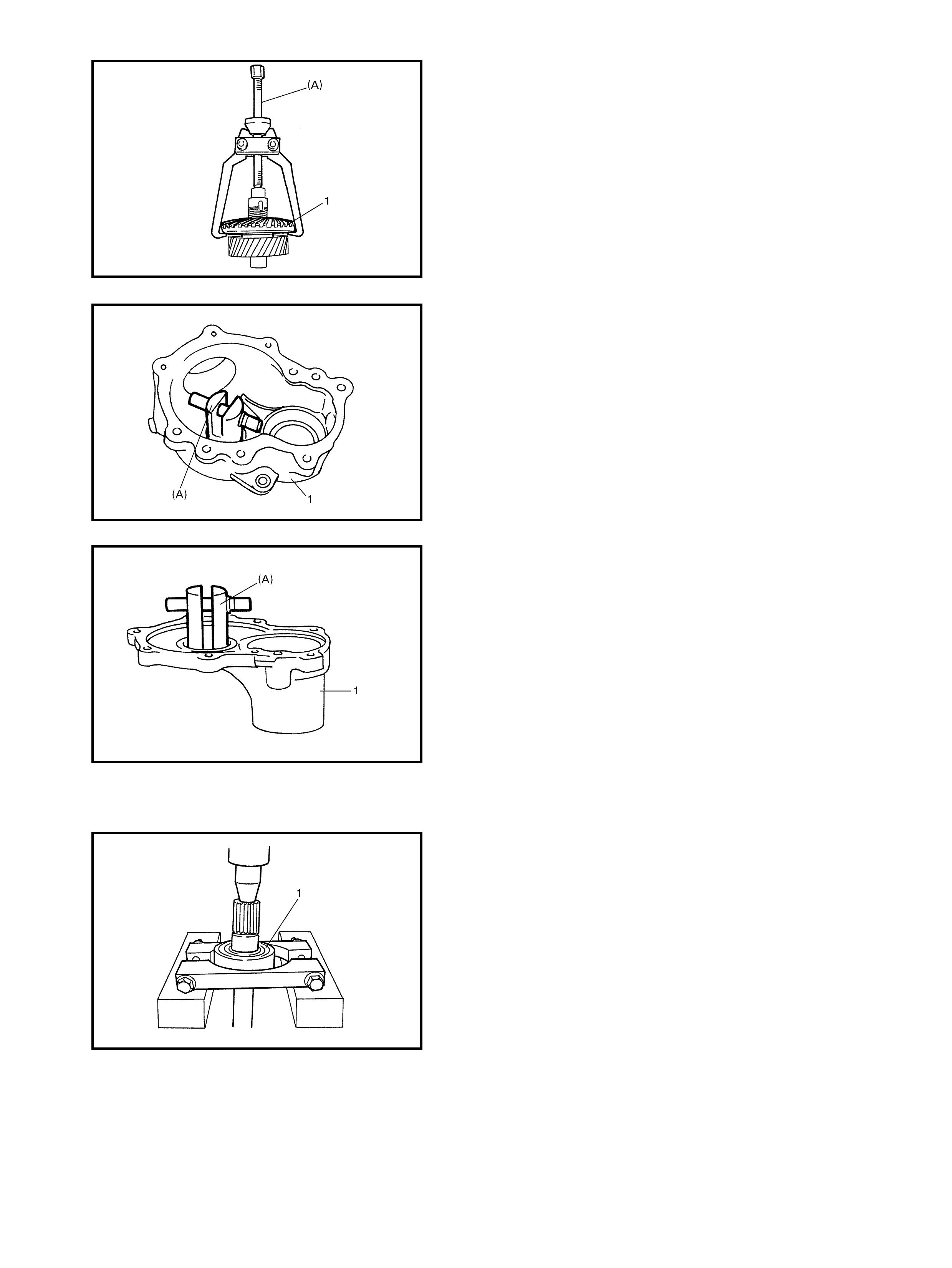
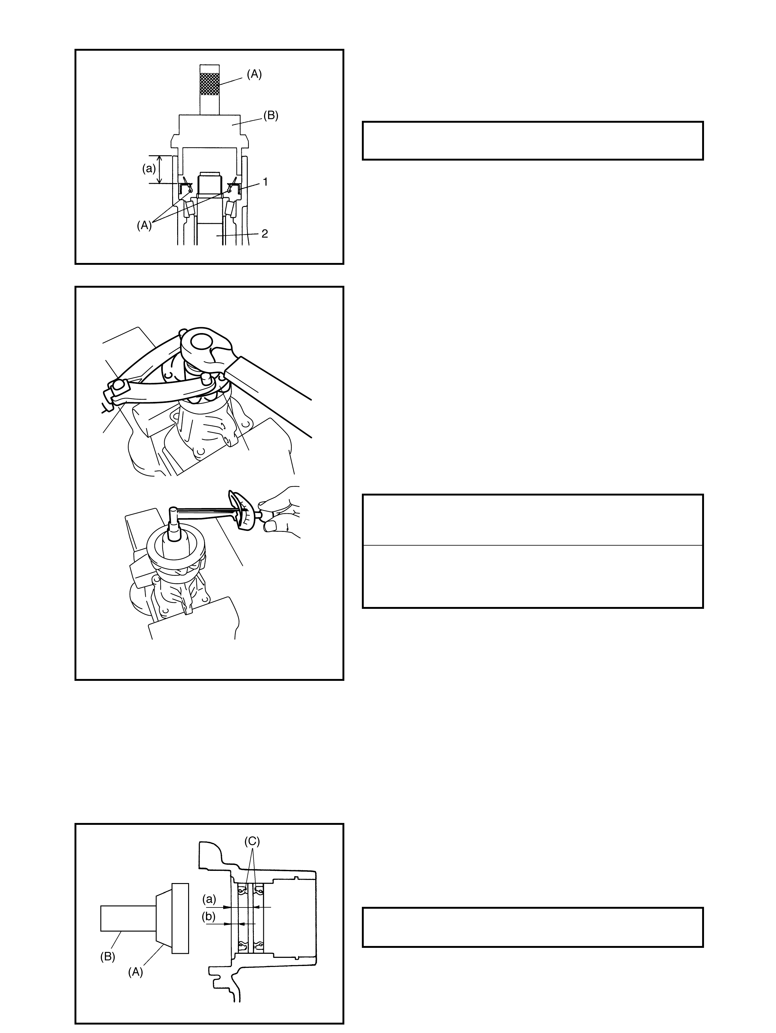
3. Remove the reduction drive gear oil seals (1) using a
hydraulic press and s pecia l tools 09924-84510-005 (A)
and 09913-75821 (B).
TRANSFER OUTPUT RETAINER ASSEMBLY
1. Unstake flange nu t.
2. Remove the flange nut while holding the flange (1)
using special tool 09930-40113 (A).
3. Remove the flange (1 ) using speci al tool 09913-609 10
(A).
4. Drive out the bev el pinion shaft from the trans fer output
retainer by tap ping with a plastic ham me r.
5. Dr ive o ut the pinion spacer from the bevel pini on shaft.
6. Drive out the pinion shaft bearing (2) from the bevel
pinion shaft (1) using a hydraulic press bearing puller
(3).
(A)
1
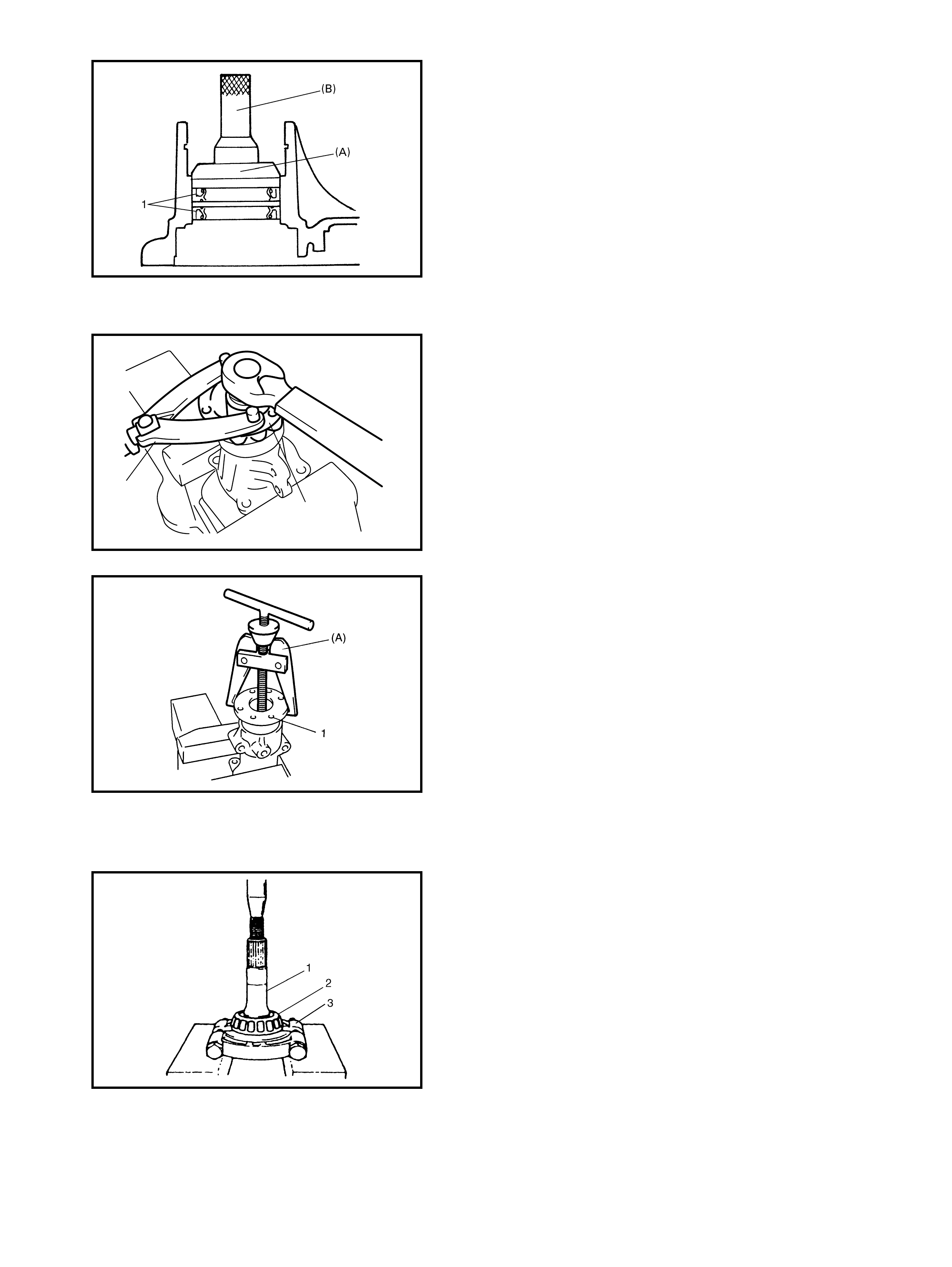
7) Remove the pinion shaft oil seal (1) using special
tool 099 13-501 21 (A) .
8. Drive out the pin ion shaft be arin g outer races (2) (front
and rear) using a brass bar (1).
4.3 COMPONENT INSPECTION
•Check each be arin g for smooth rotation, wear or disco-
louration.
If defective, replace.
•Check the oil sea ls for leakage and its lip for excessive
hardness.
If either is found, replace.
•Check the tra nsfer case fo r cracks.
•Check the bevel pinion and bevel gear for wear or
cracks.
•Check the pinion gear and pinion shaft for wear or
damage.
4.4 TRANSFER UNIT ASSEMBLY
CAUTION:
• The bevel gear and pinion must be replaced as a
set if the replacement of either becomes neces-
sary.
• When replacing taper roller bearings, replace as an
inner race and outer race assembly.
From the faulty conditions noted before removal and what
is found through a visual check of bearings and gear teeth
etc. after the unit is disassembled, obtain replacement
parts required. Assemble the transfer unit noting the follow-
ing procedures.

REDUCTION DRIVEN GEAR ASSEMBLY
1. Dr ive in the bevel gear to the reduc tion driven gear.
2. Tighten the bevel gear nut to specified torque while
holding the bevel gear with spe cial tools 09941-58020
(B), 09924-57610 (C) and vise, th en stake the nut.
NOTE: Support the shaft with special tool 09945-16070 (A)
as shown in the figure so that the retainer of the bearing
cone will not be compress ed.
3. Press-fit the driven the gear bearings ( 2) (right and lef t)
to the driven gear using a plate (1) and special tools
09945-16070.
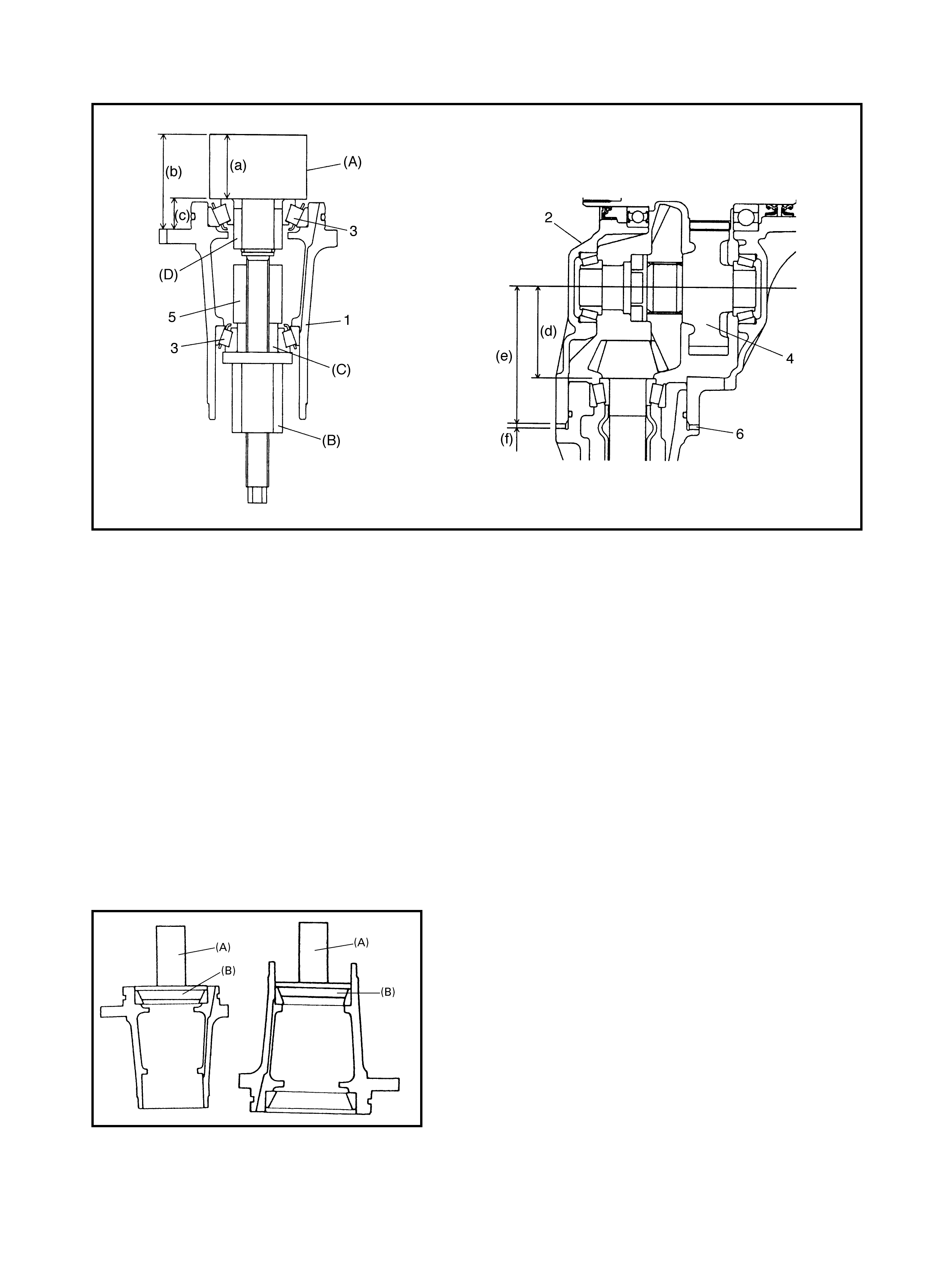
BEVEL GEAR SHIM ADJUSTMENT
4. Install the driven gear b eari ng oute r races, take a mea-
surement of the d istance (a) between the end faces of
the driv en gear bearing outer races.
5. Measure depth (b) and (c) from the mating face of the
right (1) and left (2) cases to the faces processed for
the installation of the drive n gear bearin g.
6. Calculate shim thic kness to be inserted.
S h im th ickne s s = { (b) + (c ) – (a) + 0.1 mm}/2
7. Sele ct the shim(s) closest to the calcula ted value.
TRANSFER BEVEL GEAR NUT
TORQUE SPECIFICATION 150 Nm
AVAILABLE SHIM THICKNESS 0.60, 0.65, 0.70,
0.75, 0.80, 0.85,
0.90, 0.95, 1.00 &
1.05 mm
TRANSFER OUTPUT RETAINER ASSEMBLY
Assembly and Adjustment
Legend
To e ngage the bevel pinion and ge ar correctly, it is neces-
sary to install t he bevel pinion to the transfer output retainer
correctly using adjusting shim(s) (bevel pinion shim) as
selec ted below.
Press-fit the pinion shaft bearing outer races (front and
rear) using special tools 09913-75821 (A) and 09924-
84510-005 (B).
(a): Pinion dummy (special tool) height 40 mm 3. Pinion sh aft bearing
(b): Height from retainer in stallation face to pinion
dummy top f ace 4. Reducti on driv en gear
5. Spacer
Length : 82 mm – 84 mm
Inside diameter: 14 mm
Outsid e diameter: 30 mm – 35 mm
(c): Distance from retainer install ation fac e to end
face of bearing race (b) – (a)
(d): Pinion shaft mounting distanc e 61.5 mm
(e): Distance from end f ace of left case to axis of
reduction driven gear 93.4 mm) (A): Special tool 09922-76140
(B): Special tool 09922-76150
(f): Necessary shim thickness (C): Special tool 09922-76340
1. Transfer output retainer (D): Specia l tool 09922-76430
2. Left case
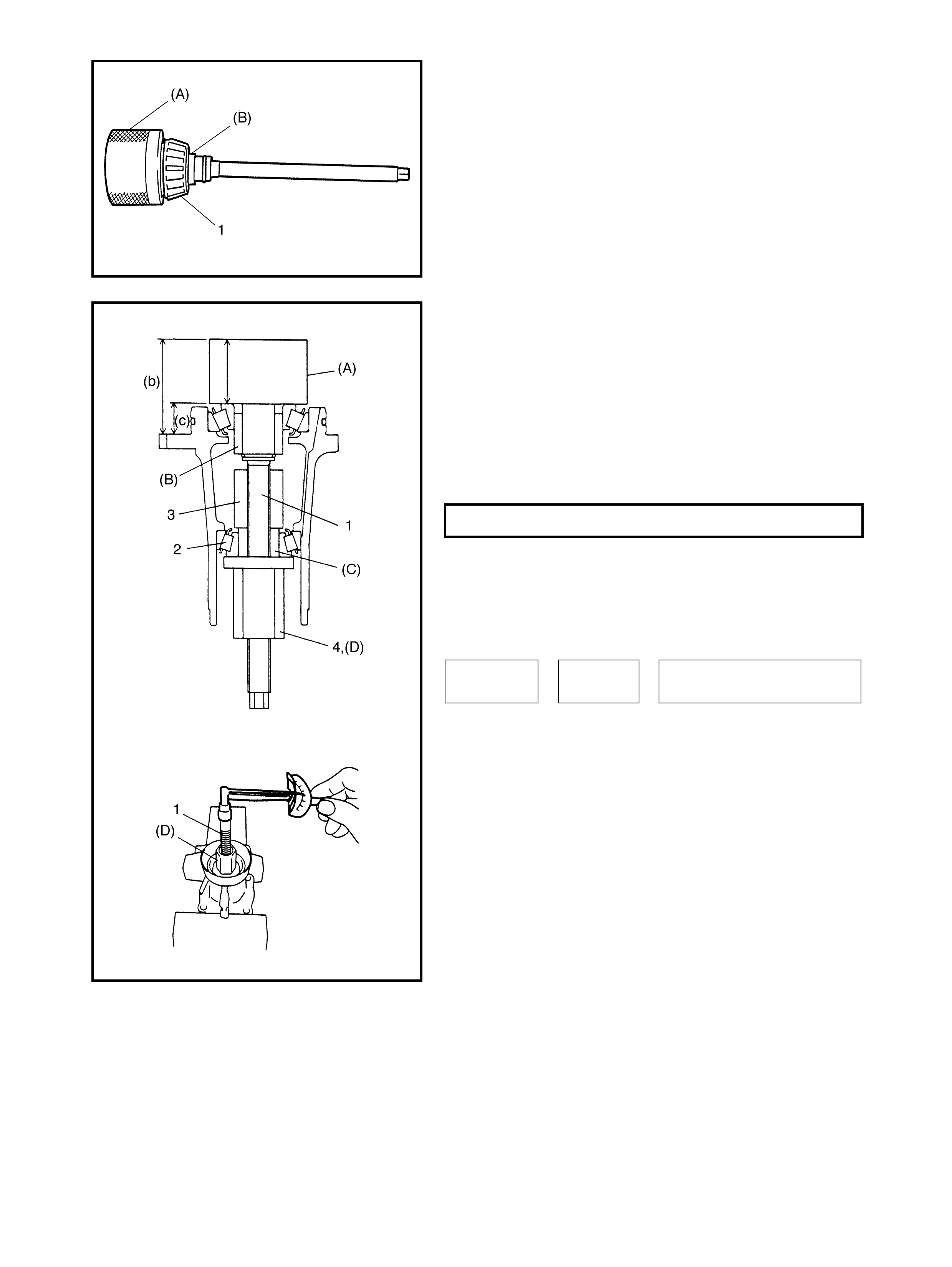
8. Install the pinion shaft bearing (1) (front side) to the
bevel pinion dummy, special tool 09922-76140 (A), with
front collar, special tool 9922-76430 (B) as shown in
the figure.
NOTE: This installation requires no spacer or oil seal.
9. Install the bevel pinion dummy (1), spacer (3), pinion
shaft bearing (2) (rear side) and special tool 09922-
76340 (C) to transfer output retainer using special tool
09922-76150 (D).
10. Tighten t he beve l pinion nu t, special tool 09922-76150
(D), so that the specified bearing preload is obtained.
NOTE: Before taking measurement, rotate the pinion shaft
by hand fo r more than 15 rev ol utions.
11. Measure the height from the transfer output retainer
installation face to the pinion dummy top face (b) using
ver n ier calipers.
Calculate t he dist ance f rom th e transfer output retainer
installation face to the end face of the bearing race (c).
PINION SHAFT BEARING PRE-LOAD 0.5 - 1.3Nm
Distance
(c) = Height (b) –Pinion Dummy Height (a)
40 mm
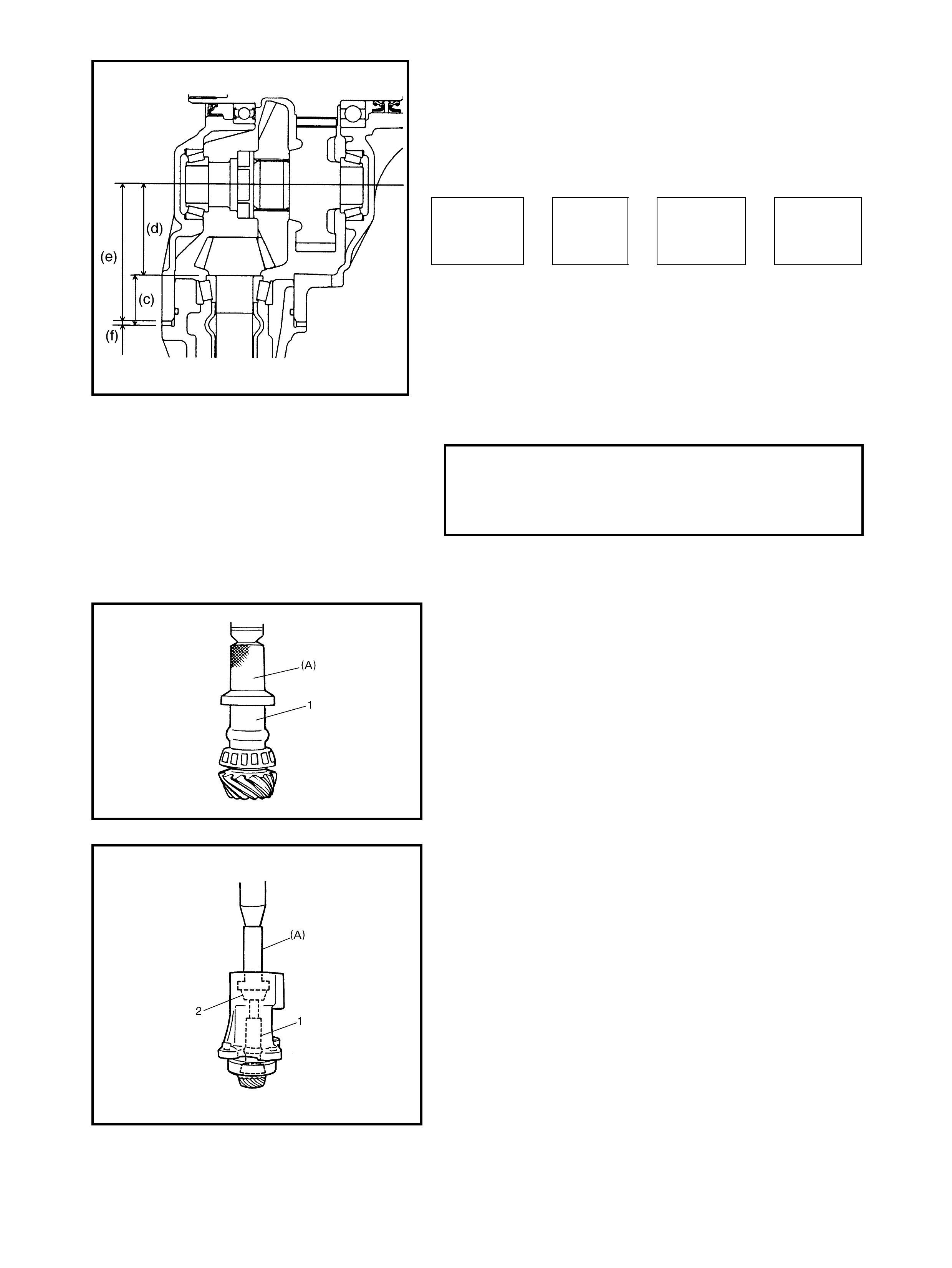
12. Obtain the required adjusting shim thickness (f) using
the calculated value (c) obtained in Step 11 in the
following equation.
The pinion shaft mounting distance (d ) is 61.5mm.
The distance from the end face of the left case to the
centre axis of the reduction driv en gear (e) is 93.4mm.
13. Select the adjusting shim closest to the calculated
val ue (f) from the foll owi ng available sizes.
14. Disassemble the bevel pinion dummy and special
tools.
15. Press-fit the pinion shaft bearing (front side) using
special tool 09913-75810 (A), hydraulic press and
pinion shaft spacer (1).
16. Install the bevel pinion shaft with a new pinion shaft
spacer (1) to the transfe r output retainer.
CAUTION: Ensure the spacer is not compressed when
press-fitting the bearing. Excessive compression may
cause a failure in the bearing preload adjustment.
17. Press-fit the pinion shaft bearing (rear side) (2) using
special tool 09913-75810 (A) and hydraulic press.
Necessary
shim thick-
ness (f)
Distance
(c ) Distance Distance
=– (e) + (d)
93.4 mm 61.5 mm
AVAILABLE SHIM THICKNESS 0.30, 2.00, 2.03,
2.06, 2.09, 2.12,
2.15, 2.18, 2.21,
2.24 & 2.27 mm
18. Drive in the new bevel pinion (2) oil seal (1) using
special tools 09924-74510 (A) and 09926-27610 (B)
and apply grease to oil seal lip.
(A): Lithium grease
19. Install the flange (1) and tighten flange nut gradually
using special tool 09939-4011 (A) so the rotational
torque of the bevel pinion shaft will not exceed the
specified val ue.
NOTE:
•If the rotational torque of the be vel pinion shaft e xceeds
the specification given below, replace the pinion shaft
spacer and tighten flang e nut.
•Before measuring the rotational torque with a torque
wrench (2), rotate the pinion shaf t more than 10 times.
•To measure the bevel pinion shaft rotational torque,
tur n the bevel pinion at about 50 r pm.3
20. Stake flange nut.
RIGHT CASE
1. Press-fit the intermediate shaft right bearing to the
inter m edia te shaft.
CAUTION: Ensure the installation direction and depth
of oil seals is correct. Failure to install them correctly
may cause oil leakage.
2. Install the new reduction drive gear oil seals (1) to case
using special tools 09924-84510-005 (A) and 09913-
75821 (B) and apply grease to oil seal lips.
(C): Lithium grease
TRANSFER BEVEL PINI ON SHAFT OIL
SEAL INSTALLATION DEPTH (a) 27.0 - 27.5 mm
TRANSFER OUTPUT FLANGE NUT
(REFERENCE)
TIGHTENING TORQUE 100 - 300 Nm
BEVEL PINIO N SHAFT
(BEARING PRELOAD)
ROTATIONAL TORQUE
SPECIFICATION 0.5 - 1.3 Nm
2
(A)
1
TRANSFER REDUCTION DRIVE GEAR
OIL SEAL INSTALLING DEPTH (a): 16.0 - 16. 5 m m
(b): 4.0 - 4. 5 mm
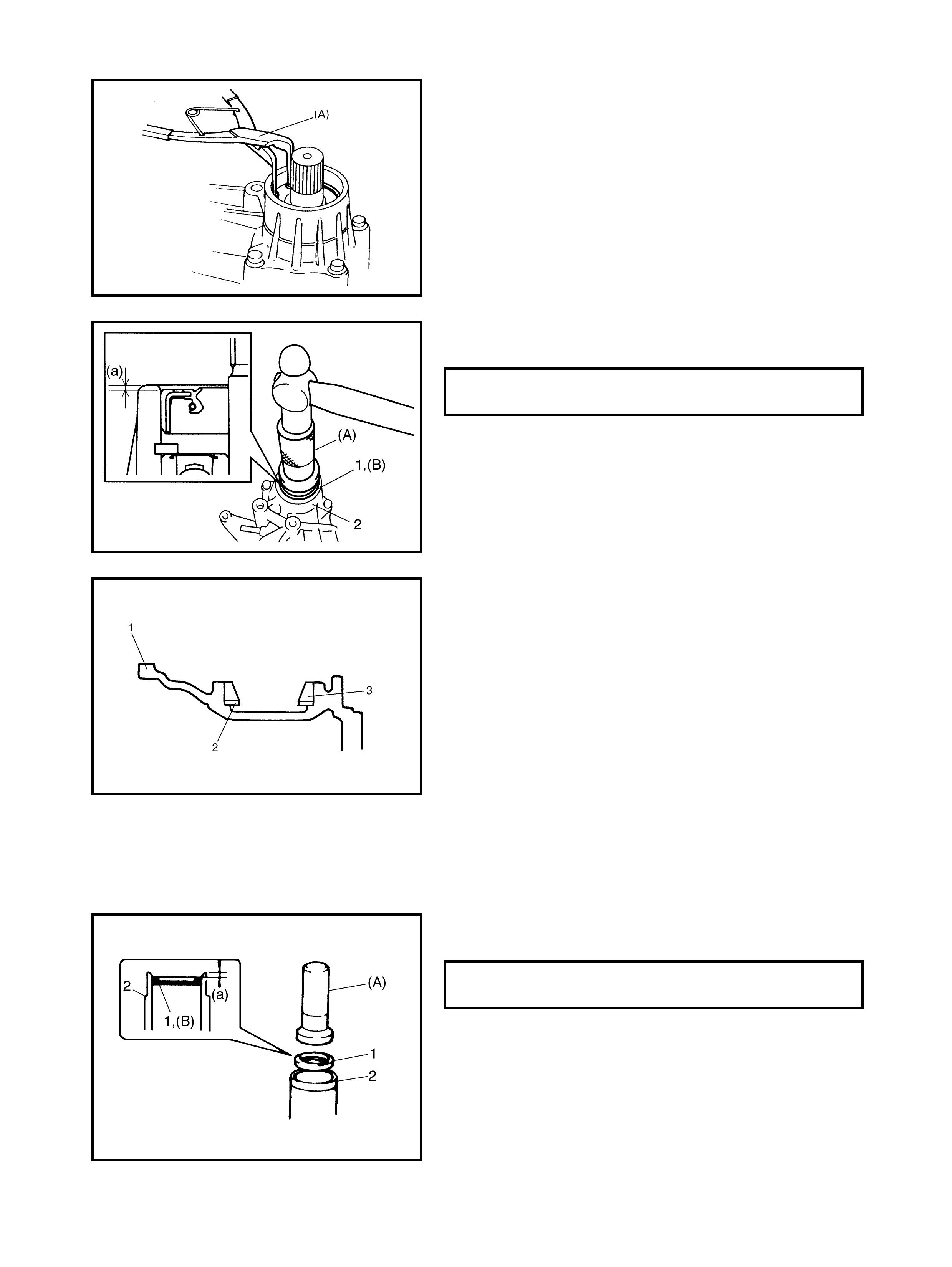
3. Install the intermediate shaft to the right case, then
install snap ring using special tool 09952-76011 (A).
4. Install the new right case oil seal (1) to the right case
(2) using special tool 09925-15410 (A).
5. Fill the inside of the oil seal with about 3 gm of grease.
Apply grease to the oil seal lip.
(B): Lithium grease
6. Install bevel gear shim(s) (2), refer to calculations
made in 4.4, UNIT ASSEMBLY, BEVEL GEAR SHIM
ADJUSTMENT in this Section, and driven gear bearing
outer race (3) to the right case (1).
LEFT CASE
1. Install the bevel gear shim(s), refer to calculations
made in 4.4, UNIT ASSEMBLY, BEVEL GEAR SHIM
ADJUSTMENT in this Section and driven gear bearing
outer race to the left cas e.
2. Install the new left case oil seal (1) to the left case (2)
using special tool 09925-15410 (A).
3 . Fill the ins ide of th e oil s eal w ith about 3 gm of gr ease.
Appl y grease to oil seal lip.
(B): Lithium grease
TRANSFER RIGHT CASE OIL SEAL
INSTALLATION DEPTH (a) 1.0 - 1.5 mm
TRANSFER LEFT CASE OIL SEAL
INSTALLATION DEPTH (a) 1.5 - 2.0 mm
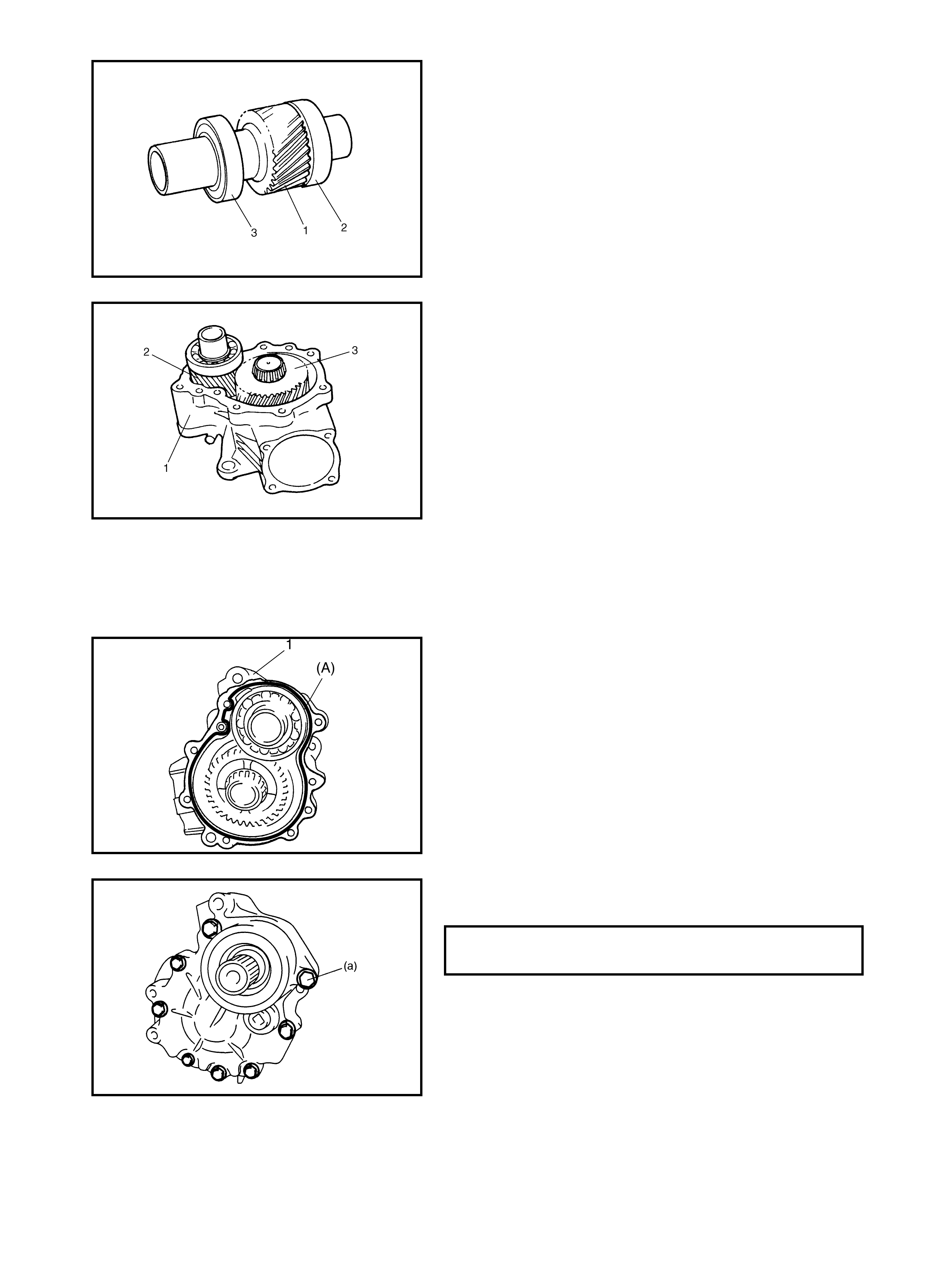
4. Press-fit the drive gear bearings [right (2) and left (3)]
to the reduction driv e gear (1).
Appl y gear oil to the ball bearin g.
5. Install the reduction drive gear assembly (2) and the
reduction dr iven gear assembl y (3) to the left case (1 ).
TRANSFER ASSEMBLY
CAUTION: Clean the mating surfaces of the left and
right transfer cases with solvent thoroughly to prevent
oil leaks.
1. Clean the mating surfaces of the right and left cases
and apply sealant to left case (1). Use a nozzle to
obtain an even 1.5 mm bead of sealant around the l eft
case mo unting surface a s shown in the figure.
(A): Sealant - Three Bond No. 1216B
2. Assemble the left and right transfer cases and tighten
the transfer case bolts to specified torque.
TRANSFER CASE BOLTS (a)
TORQUE SPECIFICATION 23 Nm
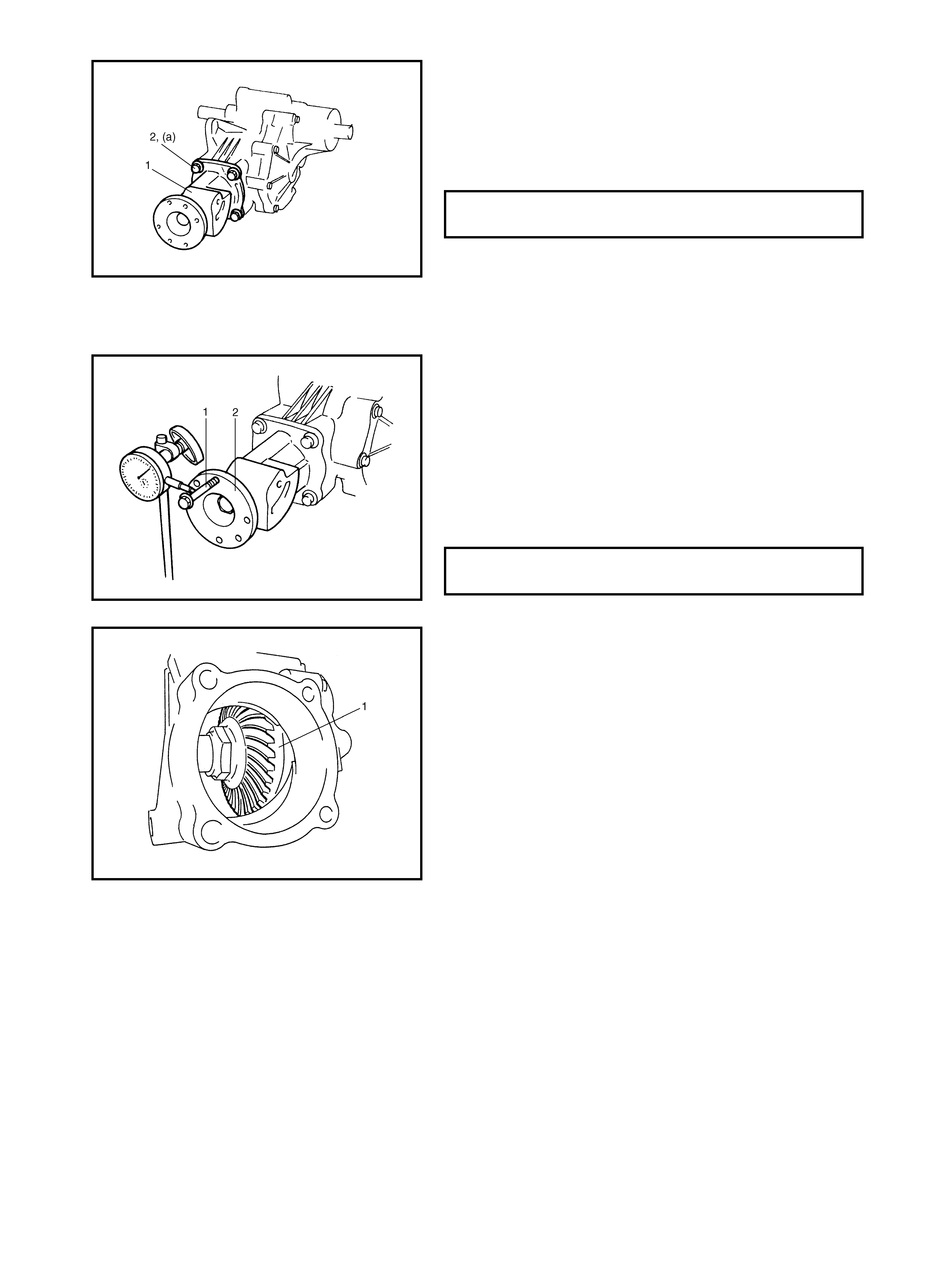
3. Install the bevel pinion shim(s) refer to 4.4 UNIT
ASSEMBLY, TRANSFER OUTPUT RETAINER
ASSEMBLY AND ADJUSTMENT in this Section. Install
the transfer output retainer assem bly (1) to the transfer
case and tighten the retainer bolts (2) to specified
torque.
4.5 BEVEL GEAR BACK LASH
MEASUREMENT
1. Install a bolt to the bolt hole of flange (2), set a dial
gauge measuring tip at right angles to the bolt (1) as
shown in the figure.
Note the measurement of the backlash of the pinion
and bevel gear.
NOTE: If the backlash exceeds specification given below,
replace the bevel pinion shim (between the transfer case
and the transfer output retainer) and measure backlash
again.
2. Finally, check gear to oth contact as follows.
NOTE: When applying red paste to teeth, be sure to paint
tooth surfaces evenly. The pas te must n ot be to o dry or too
liquid.
a. After cleaning tooth surface of bevel gear (1), paint
them with gear marking compound evenly using a
brush or sponge etc.
NOTE: Be careful not to tur n bevel gear mo re than one full
tur n, or it will hinder the accuracy of the test.
b. Turn the bevel gear until the painted section
meshes with the bevel pinion gear. Tur n it back and
forth by hand to repeat the contac t.
c. Rotate the gear until the painted section is visible
and ch eck the contact pat ter n, refer to the following
chart.
If the contact pattern is not normal, readjust or
replace as necessary
NOTE: If the bevel gear back lash and the bevel pinion
shims are adjusted properly, the correct tooth contact pat-
ter n will be evident.
If the correct tooth contact is still not evident, despite cor-
rect adjustment, there may be abnormal tooth wear or
transfer case or retainer damage. Check each component
and replace as necessary.
TRANSFER OUTPUT RETAINER
BOLTS (a) 50 Nm
TRANSFER PINION AND BEVEL GEAR
BA CKLASH 0.1 - 0.2 mm
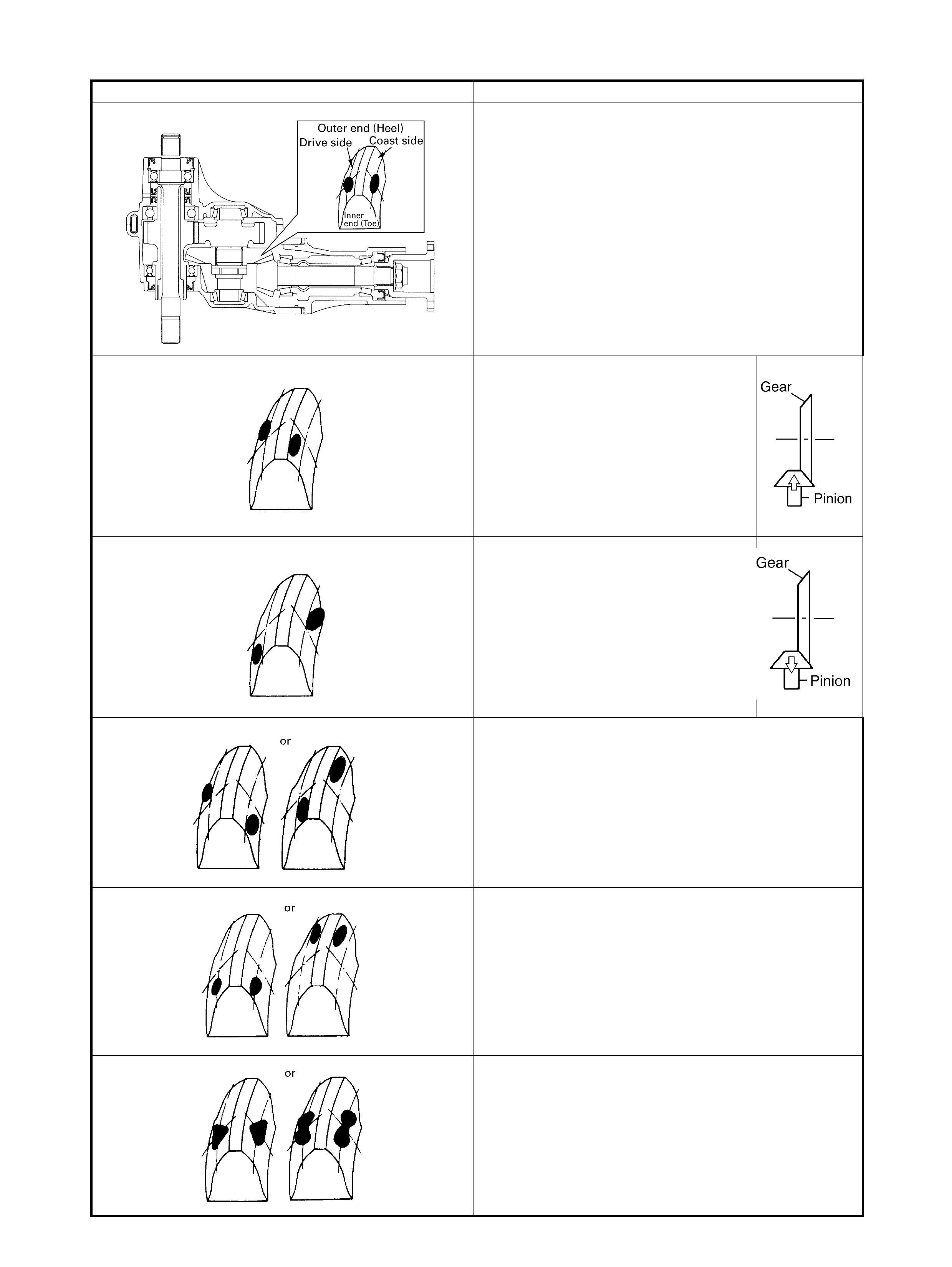
GEAR TOOTH CONTACT
TOOTH CONTACT PATTERN DIAGNOSIS AND REMEDY
NORMAL
HIGH CONTACT
Pinion is positioned too far from the
centre of the drive bevel gear .
1) Decrease the thickness of the
bevel pinion shim and position
pinion closer to gear centre.
2) Adjust drive bevel gear backlash
to specification.
LO W CONTACT
Pinion is positioned too close to the
centre of the drive bevel gear .
1) Increase the thickness of the
bevel pinion shim and position
pinion farther from gear centre.
2) Adjust the drive bevel gear back-
lash to specification.
These contact patterns indicate that the OFFSET of
the reduction driven gear is too great or too small. To
rectify, change the thickness of the bevel gear shim(s).
These contact patterns , located on the toe or heel on
both drive and coast sides, mean that 1) both the pin-
ion and gear are defective, 2) the retainer is not true
or 3) the bevel gear is not correctly seat ed in the
transfer case. To rectify, replace fau lty item(s).
Irregular patterns : If the pattern is not oval, it means
the bevel ge ar is defective. High or low s pot s on the
tooth surfaces or on the seat of the be vel gear cause
irregular patterns to appear on some teeth. To rectify,
replace the pinion and gear set and if the seat is
defective, replace the transfer c ase.
4.6 TRANSFER UNIT
INSTALLATION
Install the transfer assembly by reversing the removal pro-
cedure noting the f ol lo wing points .
•Tighten the mounting bolt and mounting bracket bolts
and nuts to specified torque.
•Tighten the transfer assembly (2) to transaxle (1)
mounting bol ts (3) to specified torque.
•Tighten the rear mounting bracket bolts (1) and mem-
ber bolts (2) to specified torque.
•Tighten the transfer stiffener bolts (1) to specified
torque.
TRANSFER REAR MOUNTING
BRAC KET NUTS (a)
TORQUE SPECIFICATION 50 Nm
TRANSFER REAR MOUNTING BOLT (b)
TORQUE SPECIFICATION 55 Nm
TRANSFER REAR MOUNTING
BRACKET No.2 BOLTS (c) 55 Nm
TRANSFER TO TRANSAXLE BOLTS (a)
TORQUE SPECIFICATION 50 Nm
TRANSFER REAR MOUNTING
BRACKET BOLTS (a)
TORQUE SPECIFICATION 55 Nm
TRANSFER REAR MOUNTING MEM-
BER BOLTS (b)
TORQUE SPECIFICATION 55 Nm
TRANSFER STIFFENER BOLTS (a )
TORQUE SPECIFICATION 50 Nm
• Tighten the transfer to engine stiffener bolts to speci-
fied torque.
• Tighten the exhaust pipe (1) bolts to specified torque.
• Install the right side drive shaft, refer to Section 4A
FRONT DRIVE SHAFTS.
•Install propeller shaft and tighten the propeller shaft
bolts and centre suppo rt bolts to specified torque (re fer
to Section 4B PROPELLER SHAFTS).
• Add gear oil to transfer as specified, refer to 3.1 OIL
CHANGE in this Section.
Check oil level and for oil l eaks.
TRANSFER TO ENGINE STIFFENER
No.1 BOLTS (a)
TORQUE SPECIFICATION 50 Nm
TRANSFER TO ENGINE STIFFENER
No.2 BOLTS (b)
TORQUE SPECIFICATION 23 Nm
EXHAUST PIPE BOLTS (a)
TORQUE SPECIFICATION 50 Nm
5. REQUIRED SERVICE MATERIAL
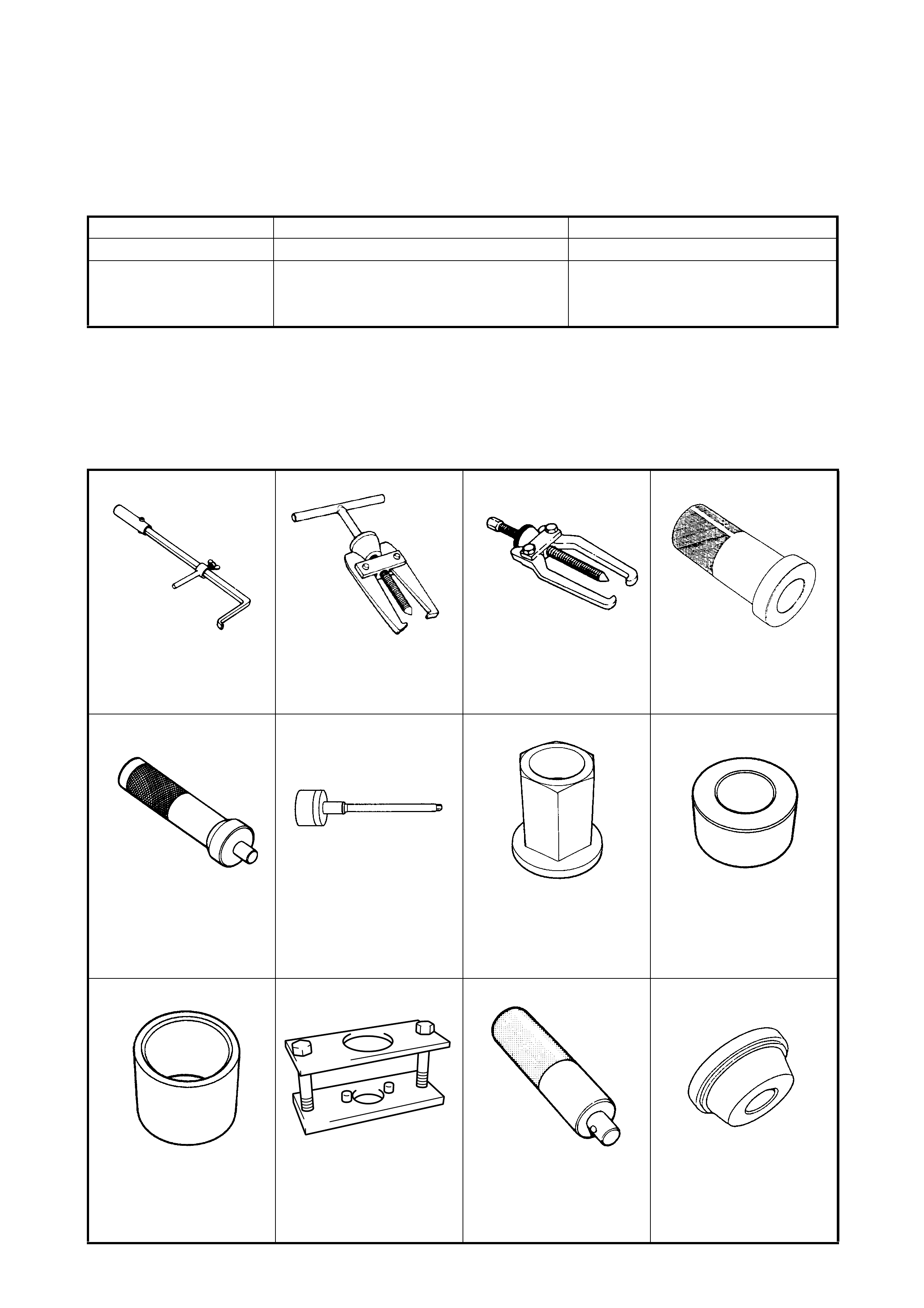
6. SPECIAL TOOLS
NOTE: Refer to Section 0A GENERAL INFORMATION – 7. CONSOLIDATED TOOLS for a detailed list of
special tools and the local equivalent if one is available.
Material Recommended product Use
Lithium grease Lithium grease
• Oil sea l lips
Sealant Three Bond No. 1216B
• Oil drai n pl ug
• Oil lev el plu g
• Mating surface of transfer case
09913-50121 09913-60910 09913-65135 09913-75810
Oil seal remover Bearing/Gear puller Bearing puller Bearing installer
09913-75821 09922-76140 09922-76150 09922-76340
Bearing installer
attachment Bevel pinion shaft Bevel pinion nut Rear collar
09922-76430 09924-57610 09924-74510 09924-84510-005
Front collar Gear holder Installer handle Bearing installer
attachment
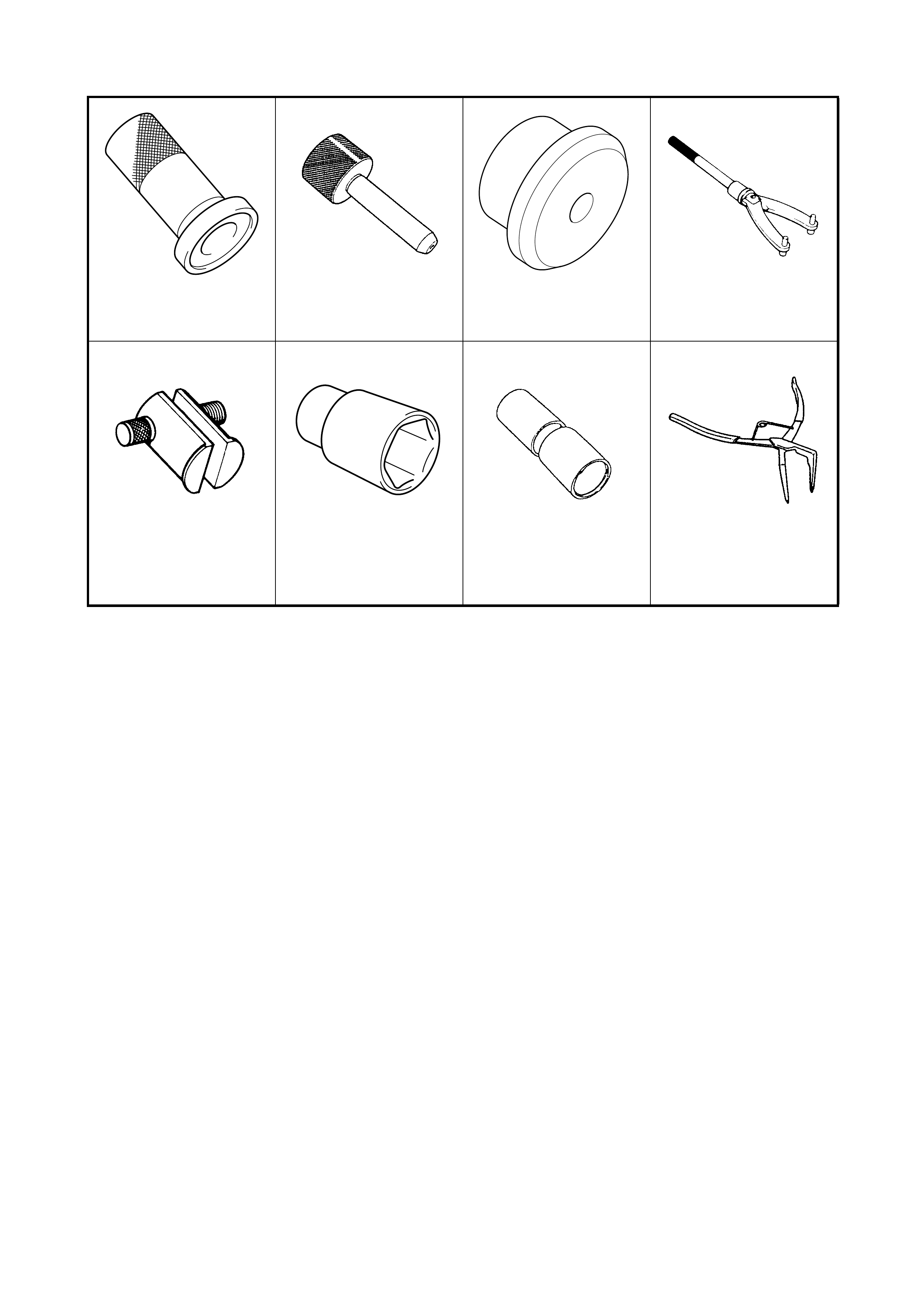
09925-15410 09925-58210 09926-27610 09930-40113
Oil seal installer Oil seal installer Oil seal installer Rotor holder
09941-54911 09941-58020 09945-16070 09952-76011
Bearing outer race
remover Socket wrench (40 mm) Retainer ring installer set Snap ring pliers
(closi ng typ e)