
1. GENERAL DESCRIPTION
The rear differential assembly features a hypoid bevel pinion an d gear which has the advantage of reduced
gear noise. During overhaul, it is imperative the hypoid gears are accurately set for tooth contact and backlash
to maintain the differential’s quiet operation.
As the differential assembly is subjected to high load forces, genuine parts must be used and all fasteners
tightene d to the spe cified torque. Further, due to t he high pre ssure sliding tooth meshi ng of the bev el pinion
and gear, hypoid gear oil is mandatory.
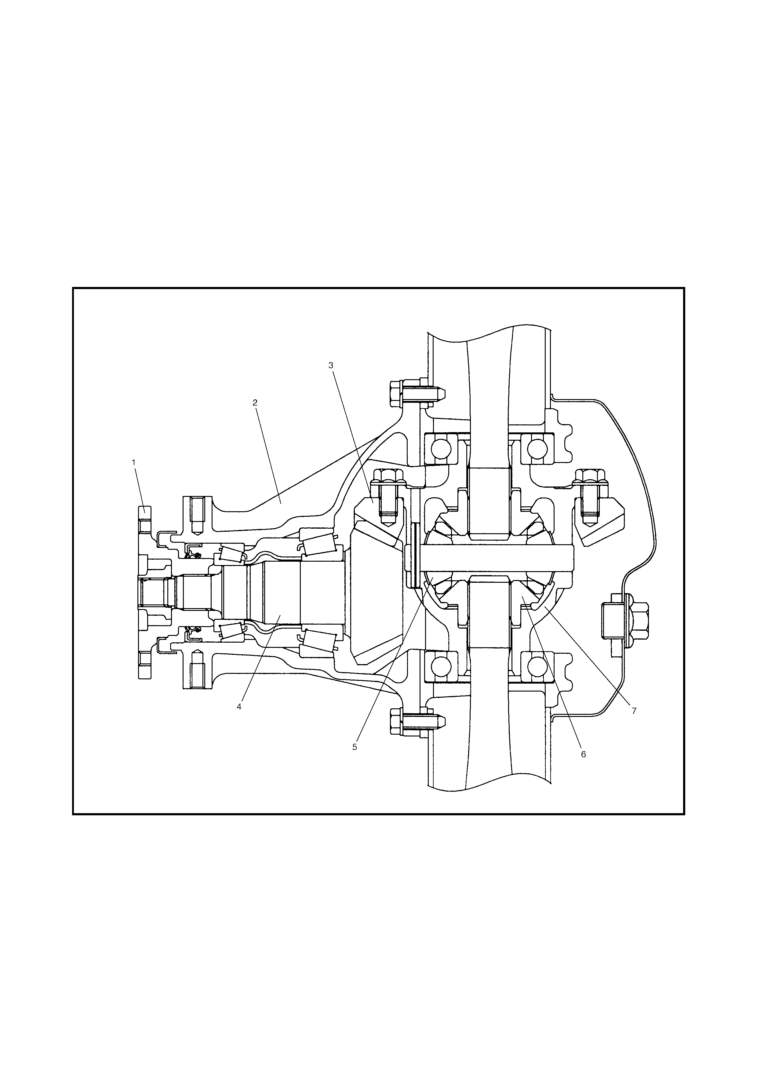
Legend
1. Companion flange 5. Differential pinion
2. Differential carrier 6. Differential side gear
3. Drive bevel gear (hypoid gear) 7. Differential case
4. Drive bevel pinion (hypoid gear)
2. DIAGNOSIS
Condition Possibl e Cau s e Correct io n
Gear noise Deteriorated or water mixed lubricant Repair and replenish.
Inadequate or insufficient lubricant Repair and replenish.
Incorrect backlash between bevel pinion and gear Adjust and prescribed.
Incorrect tooth contact in the mesh between bevel pin-
ion and gear Adjust or replace.
Loose bevel gear securing bolts Replace or retighten.
Damaged side gear(s) or side pinion(s) Replace.
Bearing noise (Constant noise) Deteriorated or water mixed lubricant Repair or replenish.
(Constant noise) Inadequate or insufficient lubricant Repair or replenish.
(Noise while coasting) Damaged bevel pinion bear-
ing(s) Replace.
(Noise while turning) Damaged differential side bear-
ing(s) Replace.
Oil leakage Clogged breather plug Clean.
Worn or damaged oil seal Replace.
Excessive oil Adjust oil level.
3. ON-VEHICLE SERVICE
3.1 OIL CHANGE
1. Before oi l cha nge or ins pecti on, sto p engin e and pl ace
vehicle on a flat surface.
2. Check the oil level and for any leakage.
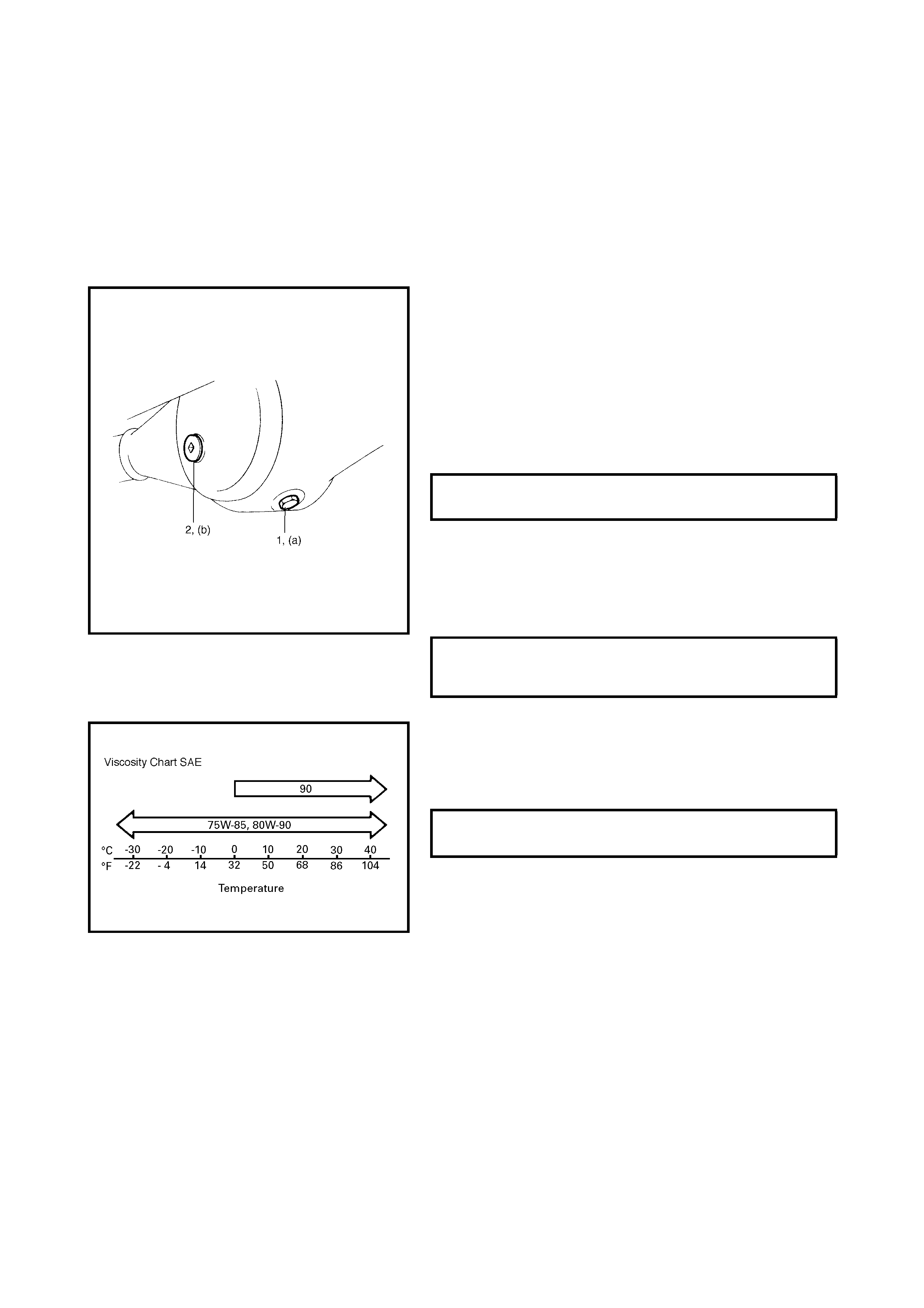
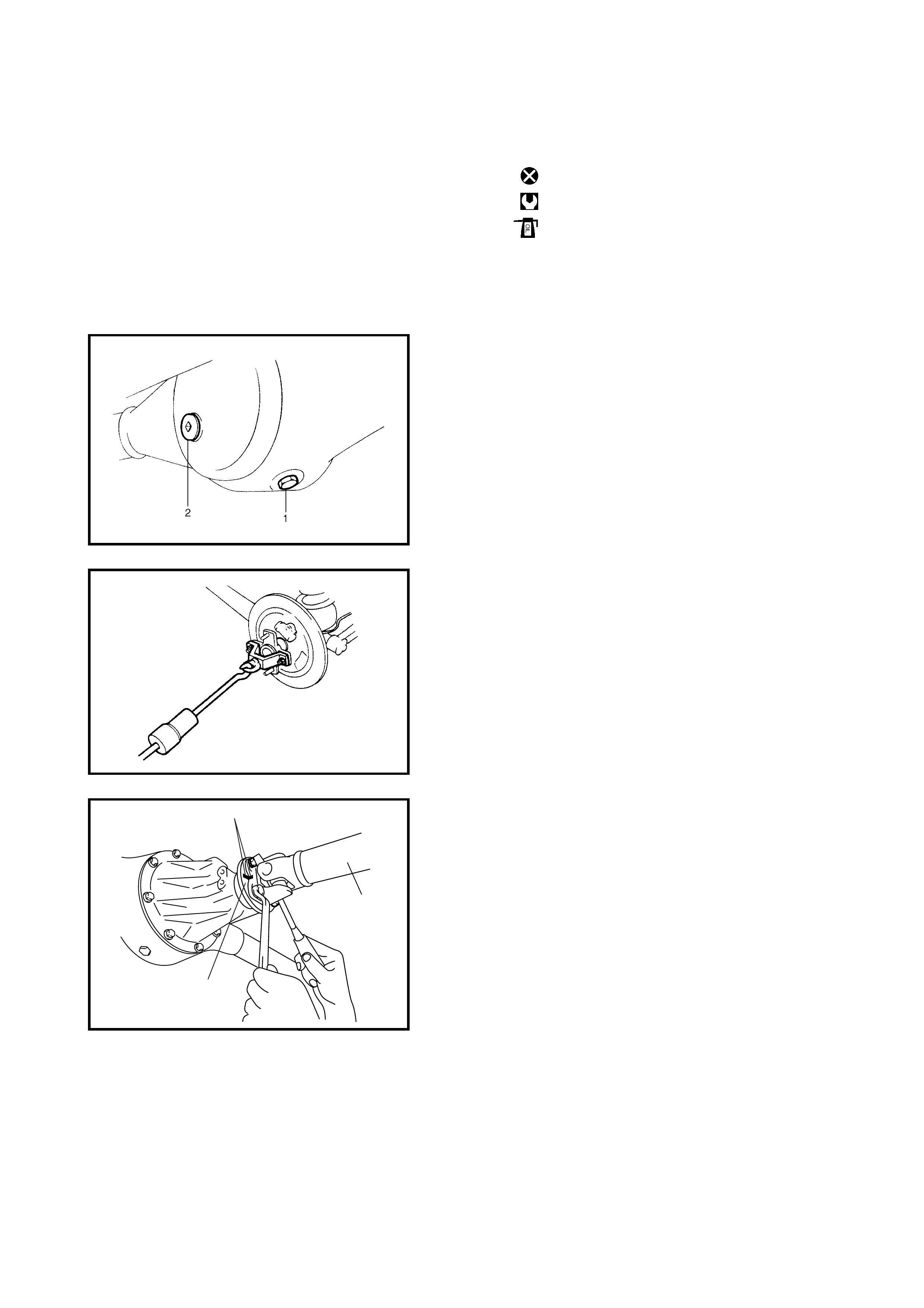
a. To check oil level, remove the level / filler plug (2).
The lower point of the level hole is the standard
level point.
b. If leakage is found, correct its cause.
3. To drain the oil, remove level / filler plug (2) and drain
plug (1), and drain the differential oil.
4. Install a new gasket onto the drain plug and tighten the
drain plug to the specified torque.
5. Fill the di fferential through the fil ler / level hole with th e
specified amount of new gear oil up to the filler / level
hole.
6. Install a new ga sket to le vel / filler pl ug and tigh ten the
plug to specified torque.
NOTE:
• It is highly recommended to use SAE 80W-90 viscosity.
•
Whenever vehicle is hoisted for any service work
other than an oil change, also check for oil leakage.
REAR DIFFERENTIAL OIL DRAIN
PLUG TORQUE SPECIFICATION (a) 55 Nm
REAR DIFFERENTIAL OIL LEVEL /
FILLER PLUG TORQUE SPECIFICA-
TION (b) 50 Nm
DIFFERENTIAL OIL: TYPE
CAPACITY API GL-5
1.0 Litr e
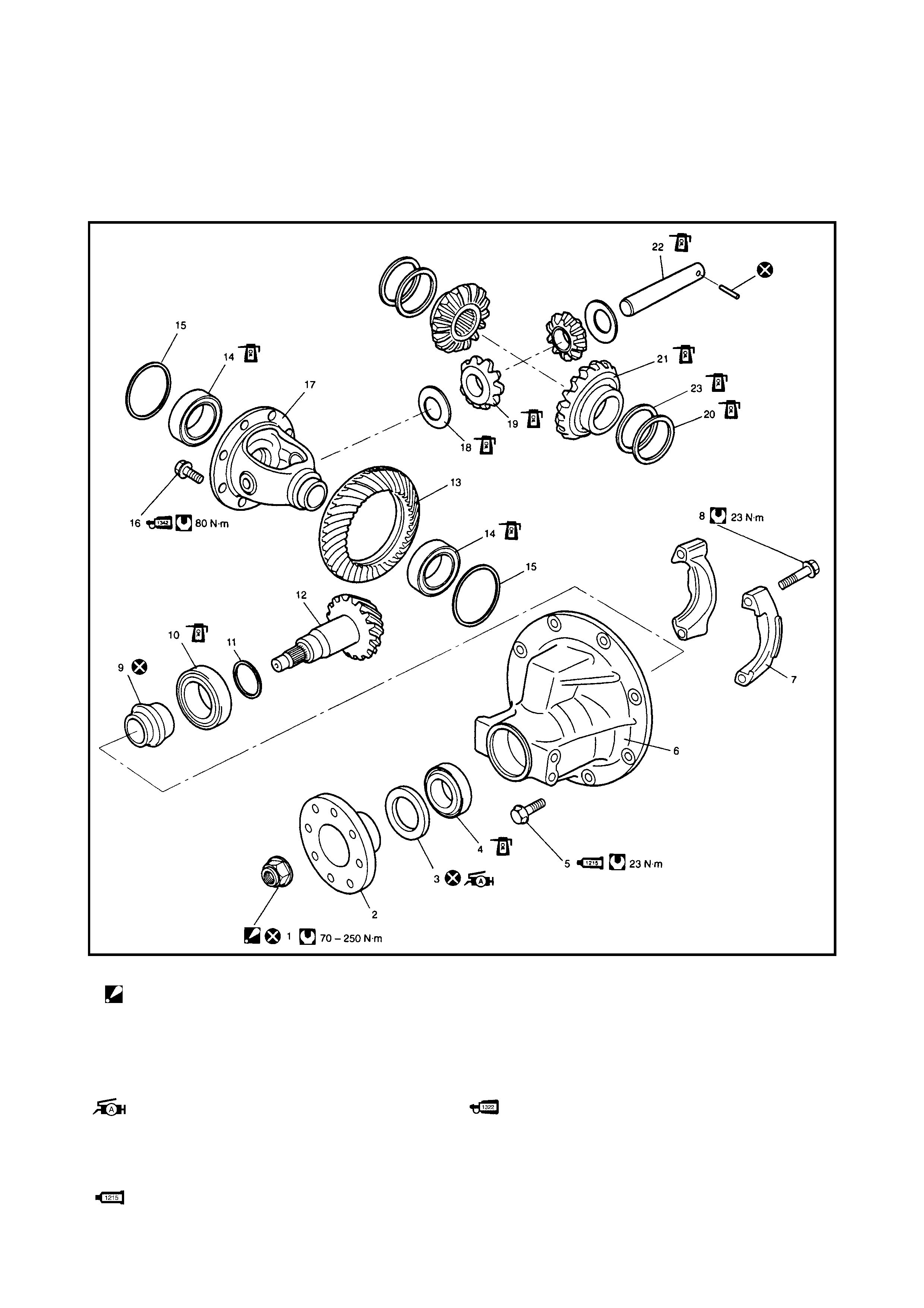
4. UNIT REP AIR OVERHAUL
Legend 1. Drive bevel pinion nut
: After tightening nut, rotational torque of
drive bevel pinion is to be within specified
torque, stake nut securely.
11. Bevel pinion shim
12. Drive bevel pinion (hypoid gear)
13. Driv e bev el gea r (hyp oid gear )
14. Dif ferential side bearing
2. Companion flange 15. Shim
3. Oil seal
: Apply Lithium grease to seal lip. 16. Drive bev el gear bolt
: Apply thread lock cement 1322.
4. Drive bevel pinion front taper roller
bearing 17. Differential case
18. Differential pinion washer
5. Differential carrier bolt
: Apply sealant Three Bond No. 1215 to
thread.
19. Differential pinion
20. Differential side washer
4.1 DIFFERENTIAL UNIT
REMOVAL
1. Hoist vehicle and remove wheels.
2. Remove th e filler plu g (2) and dr ain plug (1) and drain
the oil from rear differential, refer to 3.1 OIL CHANGE
in this Sectio n.
3. Remove the brake drum and disconnect the parking
brake cable from the brake back plate, refer to
Section 5 BRAK ES.
4. Remove the axle shafts, refer to Section 3E, 3.7 REAR
AXLE SHAFT AND WHEEL BEARING REMOVAL.
5. Before removing the propeller shaft, place matching
marks (1) on the companion flange (2) and propeller
shaft (3) as shown.
6. Differential carrier 21. Differential side gear
7. Differential side bearing cap 22. Differential pinion shaft
8. Differential side bearing cap bolt 23. Dif ferential side spring washer
9. Spacer Do not reuse
10. Drive bevel pinion rear taper roller
bearing Tightening torque
Apply differen tia l oil
3
1
2
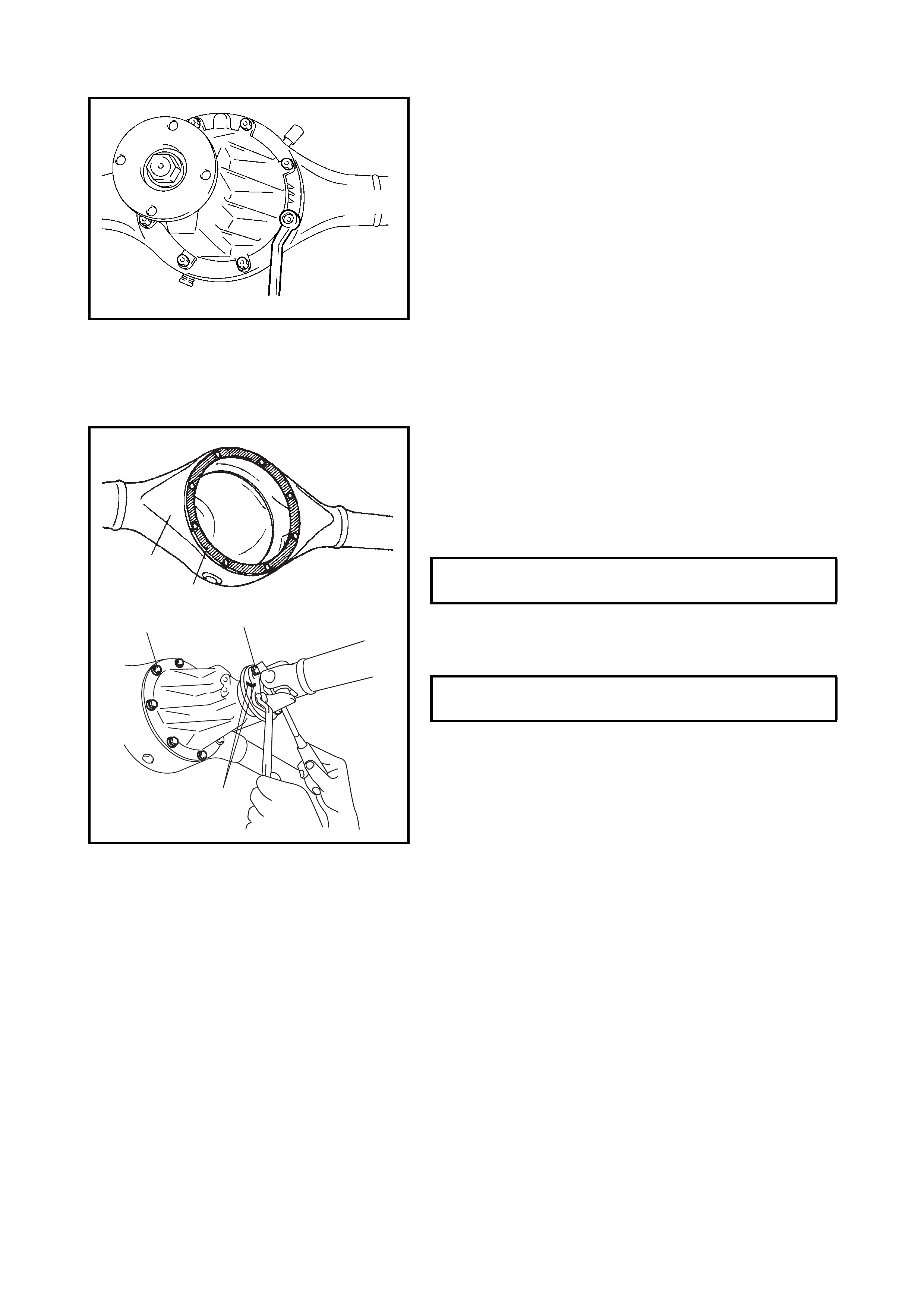
6. Remove the differential carrier bolts and the differential
assembly.
INSTALLATION
Reverse removal procedure for installation, noting the fol-
lowing.
Rear different ial
Clean the mating surfaces of the axle housing (1) and dif-
ferential carrier and apply sealant to the housing side.
(A): Sealant - Three Bond No. 1215
Apply sealant to the carrier bolts and tighten the bolts to the
specified torque.
(A): Sealant - Three Bond No. 1215
• Install the propeller shaft to the companion flange,
aligning the match marks (2). Tighten the propeller
shaft bolts to the specified torque.
Rear Axle Shaft
For installation of the rear axle shaft, refer to Section 3E,
3.7 REAR AXLE SHAFT AND WHEEL BEARING,
INSTALLATION.
Rear Brake Drum
For installation of rear brake drum, refer to Section 5,
3.3 REAR BRAKE, INSTALLATION.
Differential Gear Oil
Refill differential housing with new specified oil, refer to
3.1 OIL CHANGE in this Section.
Brake Circuit Air Purging
Purge air from the brake circuit, refer to Section 5,
3.1 AIR BLEEDING BRAKE OF SYSTEM.
Then ensure that the joint seam of the pipes is free from oil
leaks.
DIFFERENTIAL CARRIER BOLT
TORQUE SPECIFIECATION (a) 23 Nm
PROPELLER SHAFT BOLT TORQUE
SPECIFICATION (b) 23 Nm
(a),(A) (b)
2
2
(A)
1
DISASSEMBLY
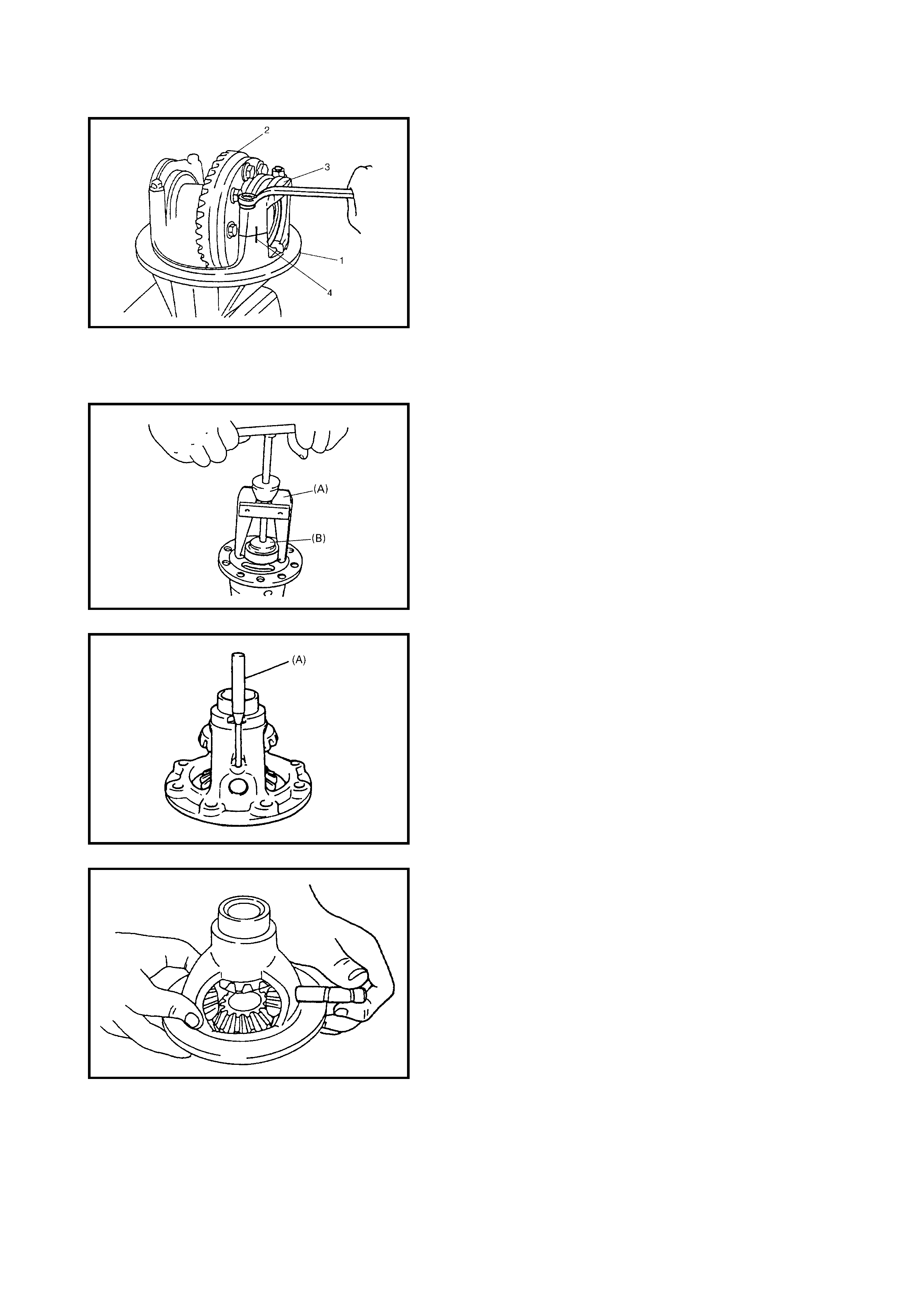
1. Make matching marks (4) on the differential side
bearing caps (3) and differential carrier (1).
NOTE:
Check
the
number of shims and
the
thickness of
each shim
.
2. Remove the differential side bearing bolts and caps
and remove differential gear assembly (2) and shims.
3. Place the differential case in a vise fitted with
aluminium soft-jaws and remove the drive bevel gear
bolts and the gear.
4. Using special tools
09913-60910
(A)
and
09925-
88210
(B)
, remove the differential side bearings.
5. Drive out the spri ng pin with spe cial tool
09922-85811
(A)
.
6. Remove the differential pinion shaft.
7. Remove the differential side gears, pinions and
washers.
8. Unstake the drive bevel pinion nut.
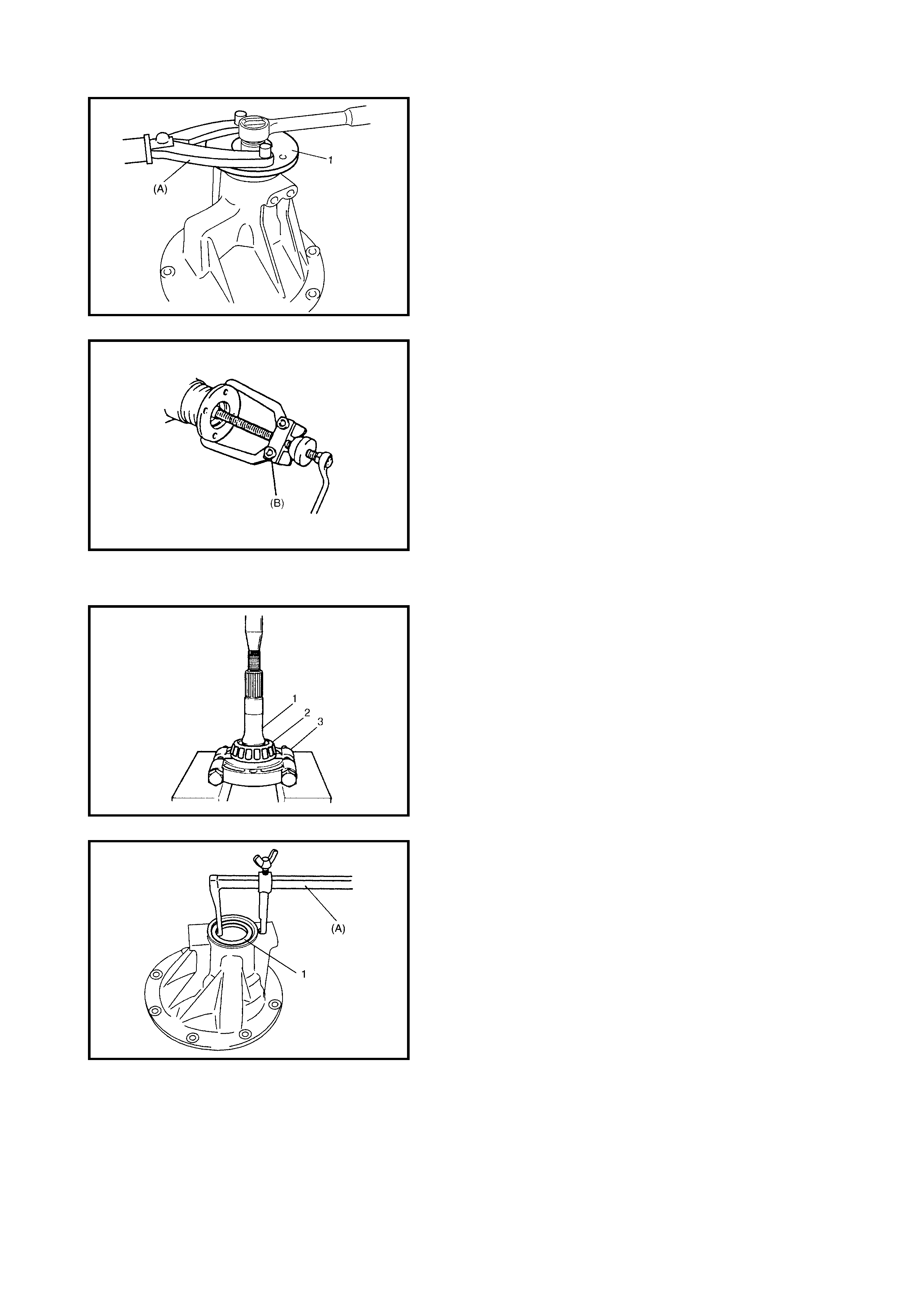
9. Hold the companion flange (1) with special tool
09930-
40113
(A)
and then remove the drive bevel pinion nut.
10. Remove the companion flange from the drive bevel
pinion.
Use special tool
09913-65135 (B)
if it is difficult to
remove.
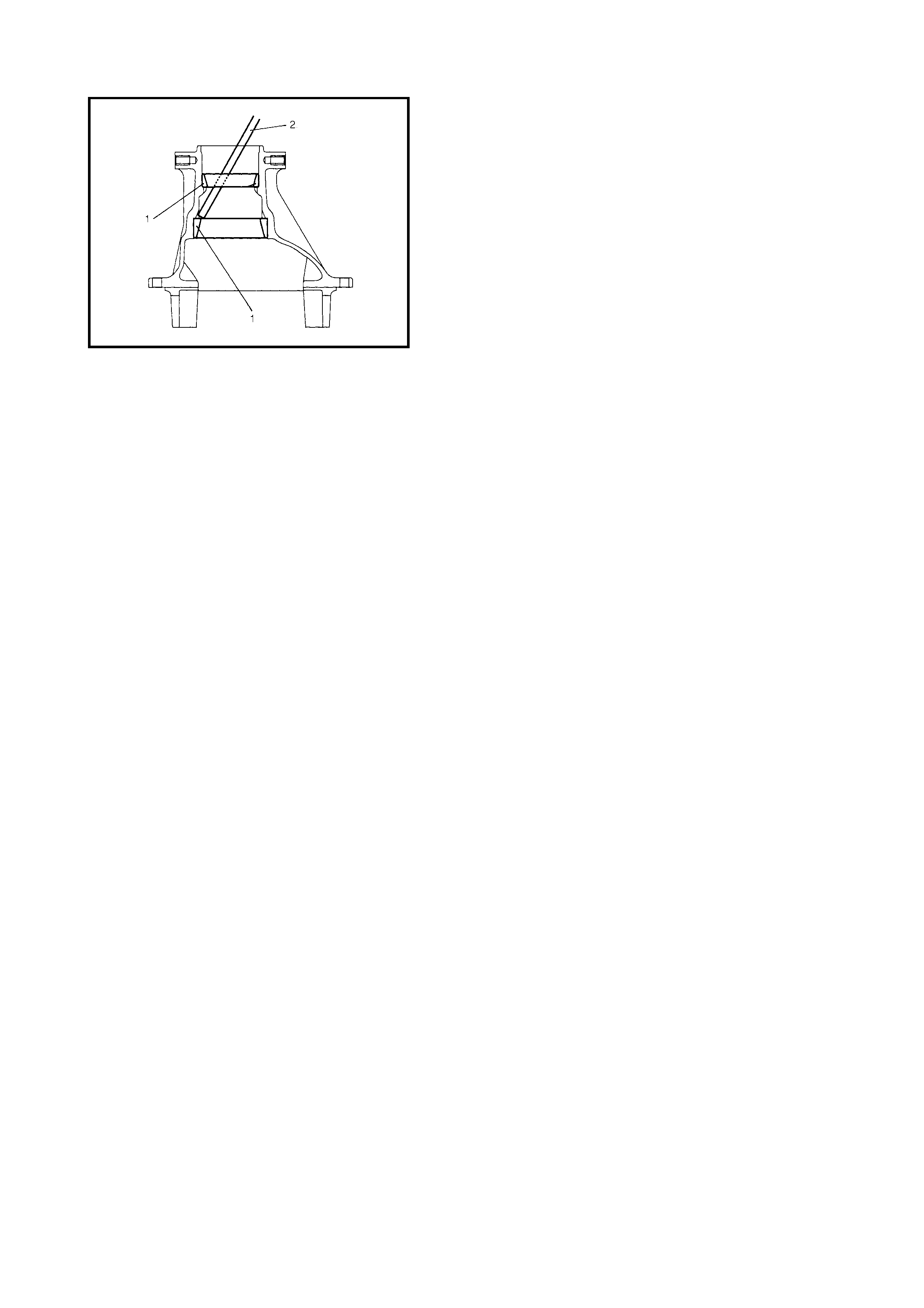
11. Remove the drive bevel pinion with the rear bearing
and spacer from the differential carrier.
12. Remove the drive bevel pinion rear bearing (2) from
the drive bevel pinion (1) by using a bearing puller (3)
and hydraulic press.
13. Remove the oil seal (1) from the differential carrier
using special tool
09913-50121
(A)
.
14. Remove the drive bevel pinion front bearing.
15. Drive o ut th e d ri ve b e ve l pin io n be aring outer r aces ( 1)
using a brass bar (2).
INSPECTION
• Check the companion flange for wear or damage.
• Check the bearings for wear or discolouration.
• Check the differential carrier for cracks.
• Check the drive bevel pinion and bevel gear for wear or
cracks.
• Check the s ide ge ar s, p inion g ear s and pin ion sh aft for
wear or damage.
• Check the side gear spline for wear or damage.
ADJUSTMENT AND ASSEMBLY
CAUTION:
• The drive bevel gear and pinion must only be
replaced as a set.
• When replacing a taper roller bearing, replace as
an inner & outer race assembly.
Judging from faulty conditions noted before disassembly
and what is found through visual check of the bearing and
gear tooth, etc. after disassembly, prepare replacing parts
and proceed to reassembly according to procedures as
described below. Make sure that all parts are clean.
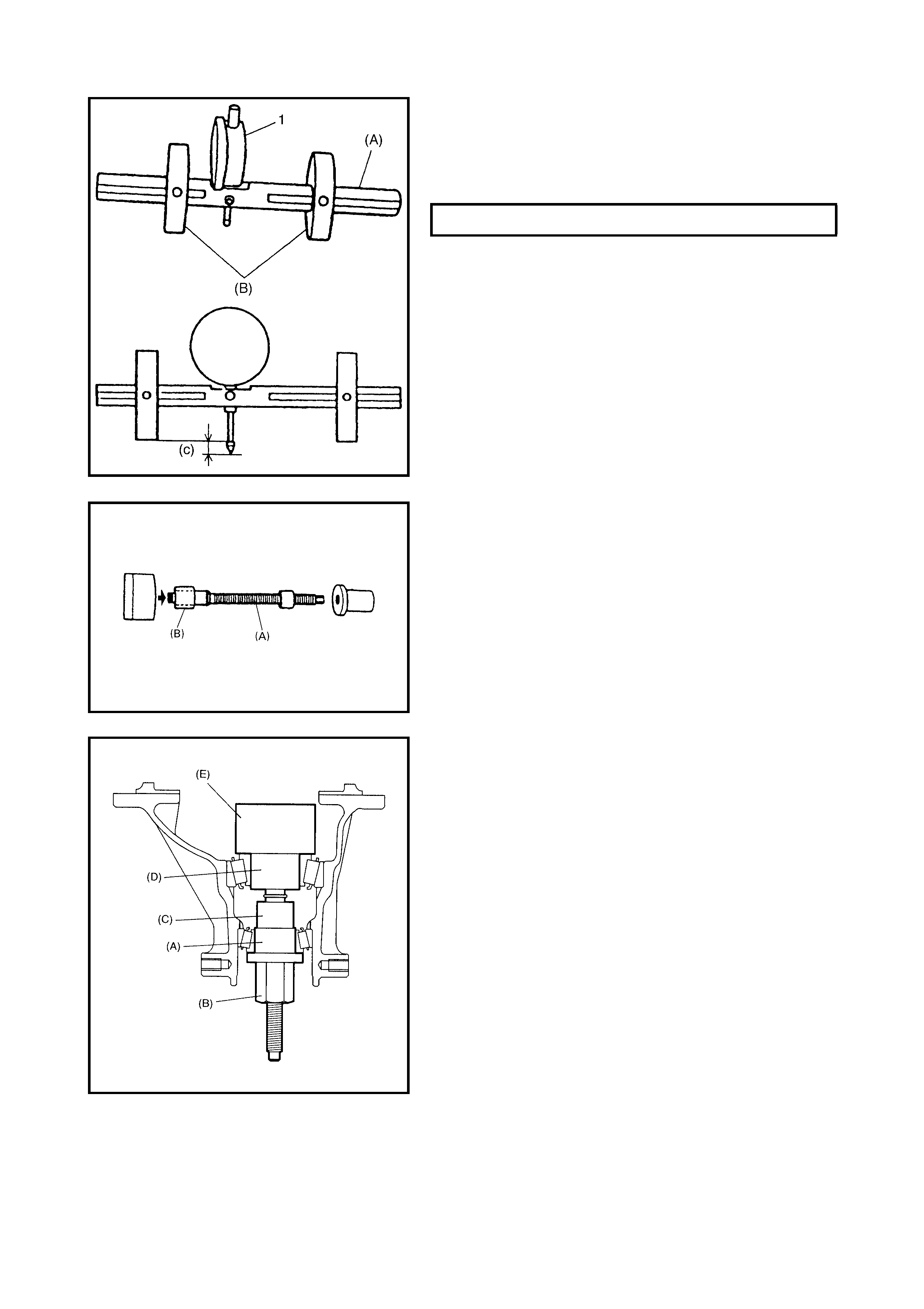
Drive bevel pinion beari ng outer race
CAUTION:
Perform press-fitting carefully keeping
components straight .
For press-fitting the bevel pinion bearing outer races, use
special tools
09925-98210
(A),
09941-34513-004 (B),
09924-74510
(C) and
09951-16090
(D)
as shown.
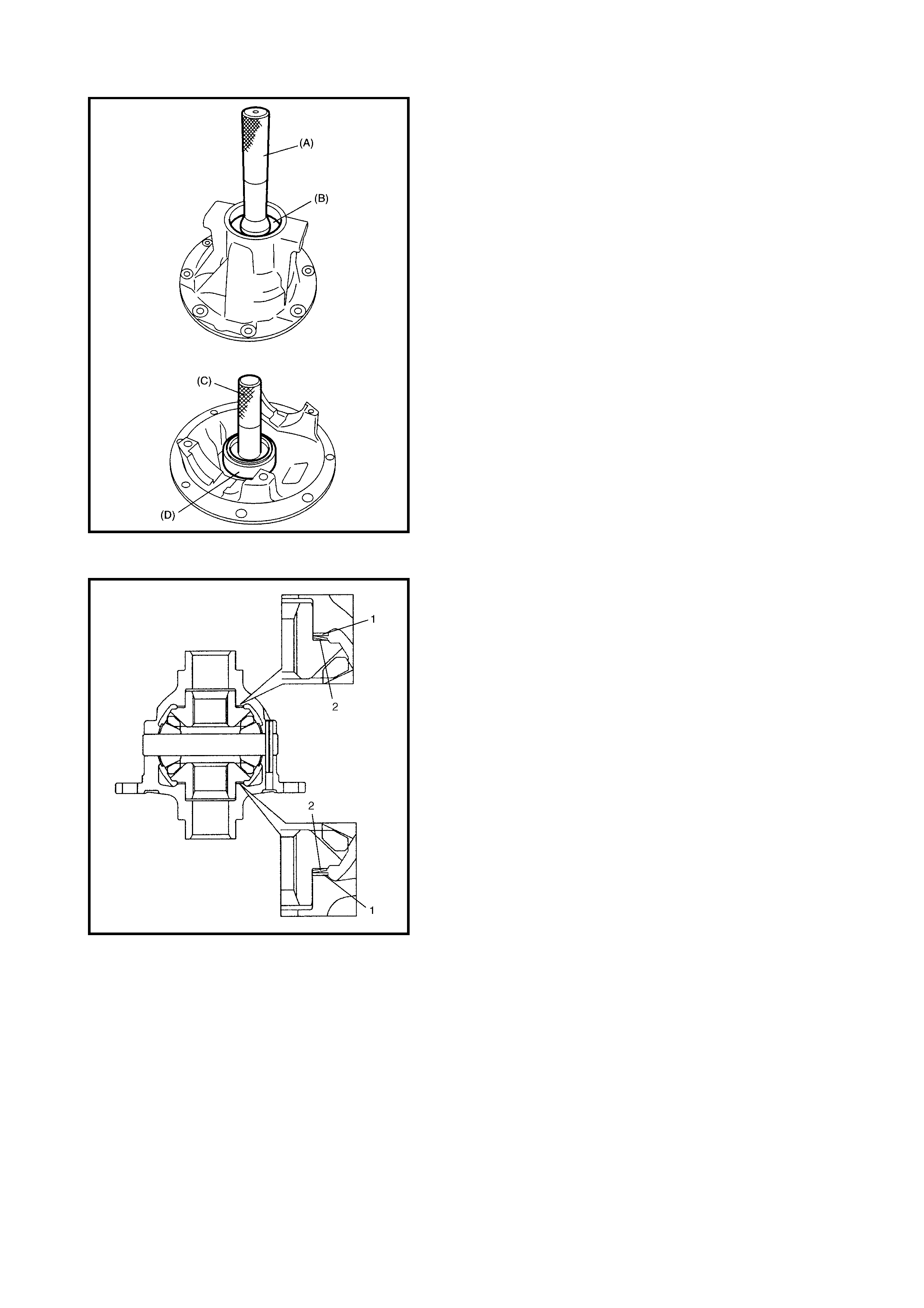
Differential case assembly
1. Assemble the differential case assembly, noting the
installation position and direction of the dif ferential side
washer (1) and spring washer (2).
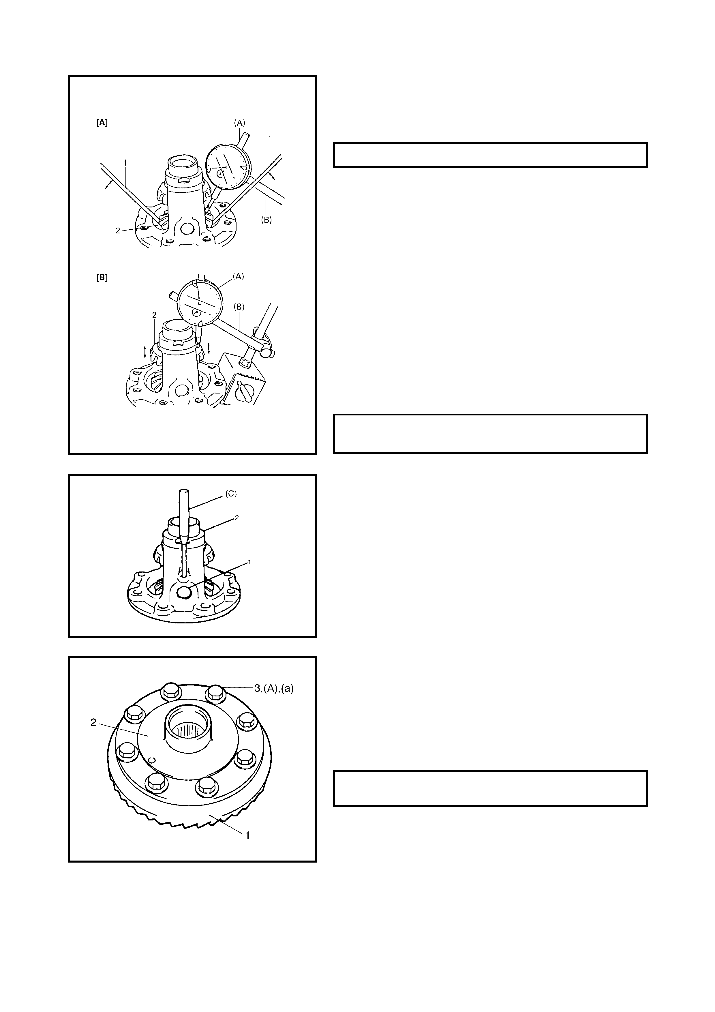
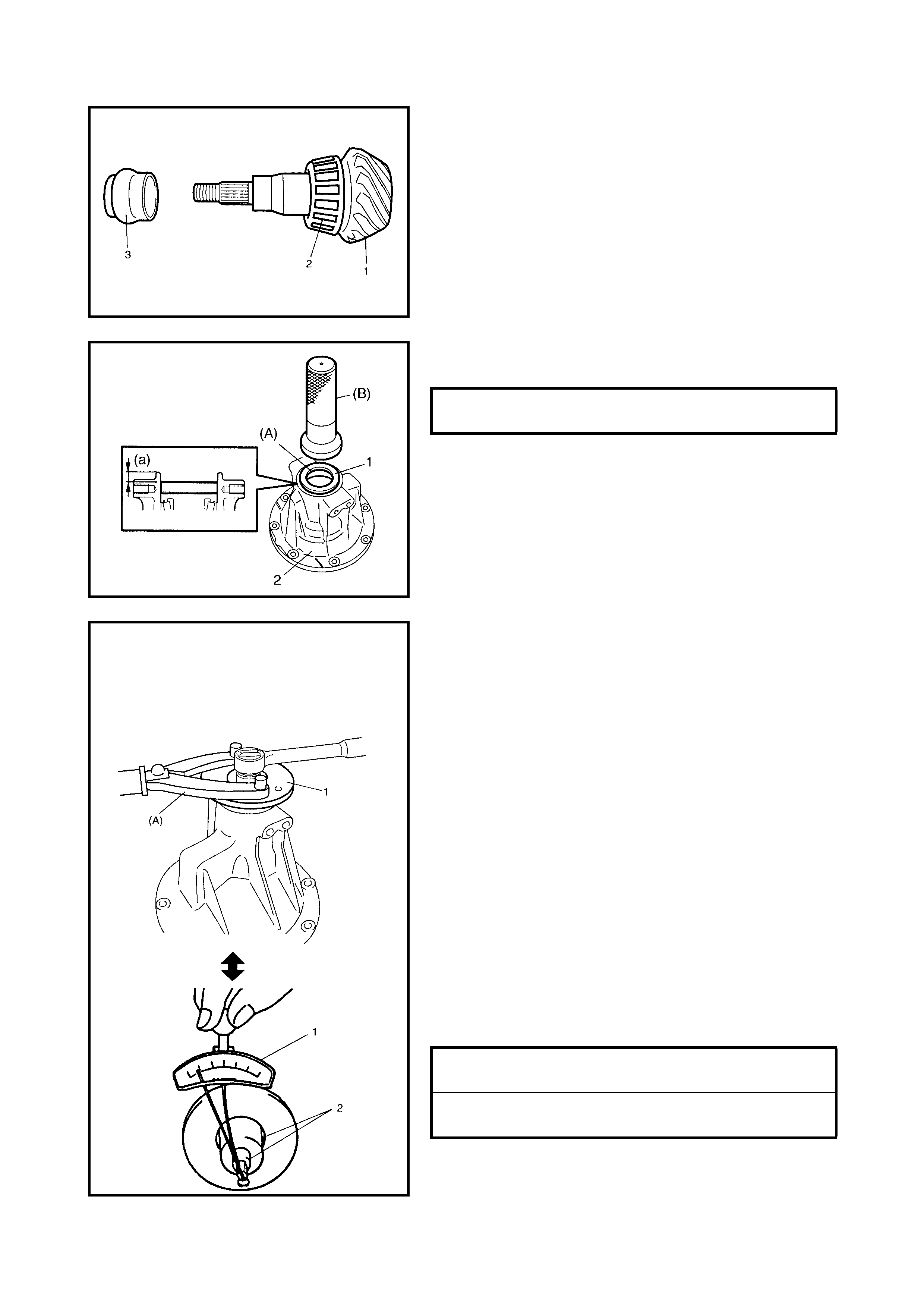
2. Measure thr ust play of the di fferential gear (2) on both
the right-hand side [A] and left-hand side [B] using
special tools
09900-20607
(A)
and
09900-20701
(B)
as follows.
Right side
• Hold the differential assembly in a vise fitted with soft
jaws and apply measuring tip of the dial gauge to the
top surface of the gear (2).
• Using two screwdrivers (1), move the gear (2) up and
down and read the movement of the dial gauge pointer .
Left side
• Using a similar procedure to the above, set the dial
gauge tip to the gear shoulder.
• Move the gear (2) up and down by hand and read the
dial gauge.
3. If the thrust play is out of specification, select a suitable
side wash er from among the following sizes available,
install it and rech eck th at the spec ified gear th rust play
is obtained.
4. Drive in a new s pring pin fo r the differential side pi nion
shaft (1) with special tool
09922-85811
(C),
until it is
flush with the differential case surface (2).
5. Put the drive bevel gear (1) on the differential case (2).
CAUTION:
Use of any bolts other than that specified
is prohibited.
6. Apply t hread lock cement to th e drive bevel gear b olts
(3) and fasten the d rive bevel gear (1) on the differen-
tial case (2) by tightening the bolts to specified torque.
(A): Thread Lock Cement 1322
DIFFERENTIAL GEAR THRUST PLAY 0 - 0.37 mm
SIDE WASHER THICKNESS AVAIL-
ABILITY
0.10, 0.30,
0.50, 0.70 mm
DRIVE BEVEL GEAR BOLT (a)
TORQUE SPECIFICATION 80 Nm
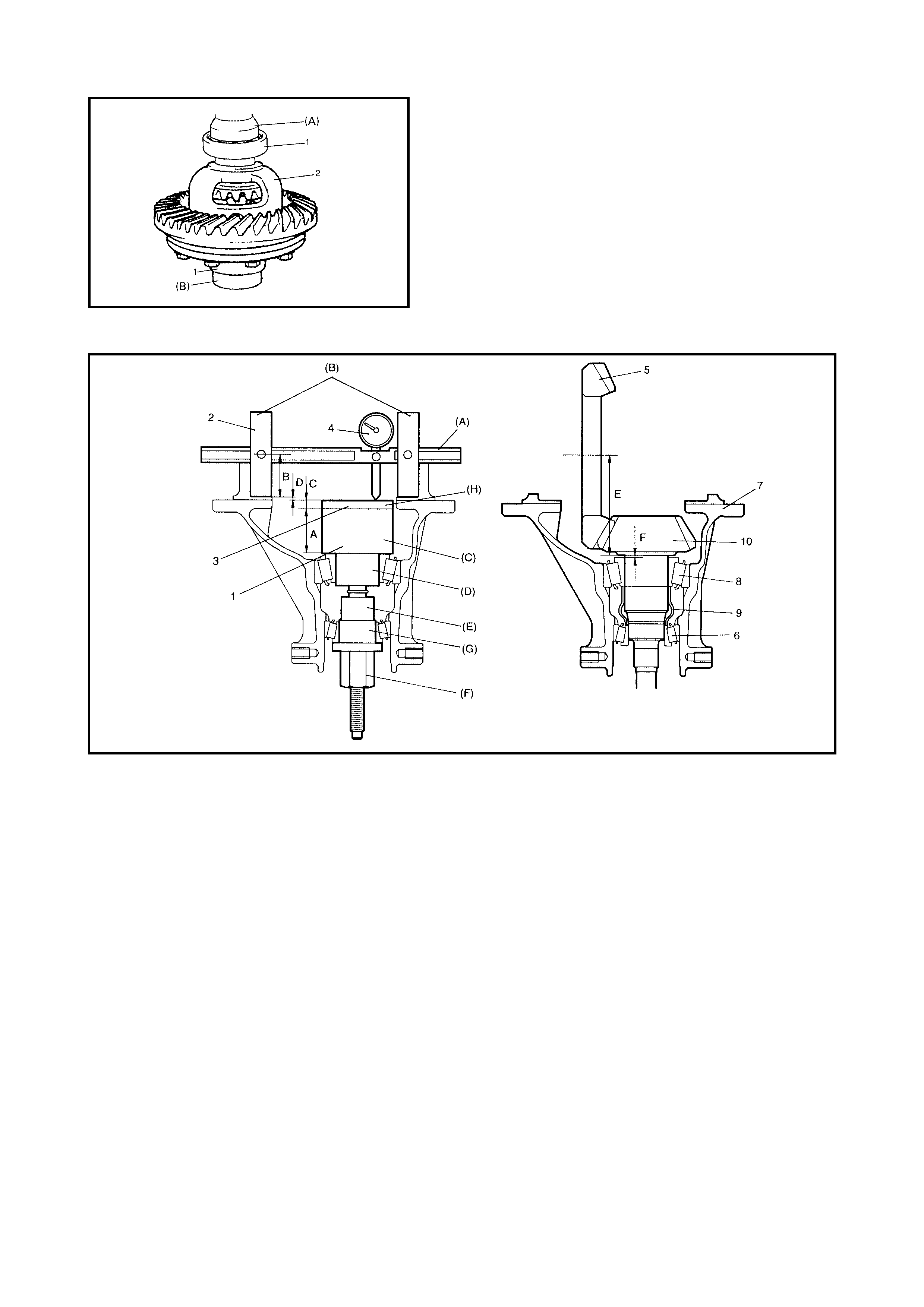
7. Press-fit the differential side bearings (1) to the differ-
ential case (2) using special tools
09951-76010
(A)
and
09951-16060
(B)
.
Different ial carrier and drive bevel pinion
Legend
A: Dummy height of pinion form dummy (40 mm) 7. Differential carrier
B: Radius of bearing form dummy with dummy shaft (36 mm) 8. Rear bearing
C: Block dummy thickness (4 mm) 9. Spacer
A+B+C: Mounting distance adjusting dummy total size (80 mm) 10. Drive bevel pinion
D: Measured dimension (A) Special tool 09922-76120
E: Drive bevel pinion mounting distance (80 mm) (B) Special tool 09922-76230
F: Shim thickness for mounting distance adjustment (D) (C) Special tool 09922-76140
1. Pinion form dummy (D) Special tool 09922-76410
2. Bearing form dummy with dummy shaft (E) Special tool 09922-76340
3. Block dummy (F) Special tool 09922-76150
4. Dial gauge (G) Special tool 09922-76320
5. Drive bevel gear (H) Special tool 09922-76510
6. Front bearing
1. Assemble the bearing form dummy with the dummy
shaft using special tools 09922-76120 (A) and 09922-
76230 (B).
2. Install the dial gauge (1) to the bearing form dummy
with dummy shaft as shown.
3. Assemble the pinion form dummy using special tools
09922-76140
(A)
and
09922-76410
(B)
.
NOTE:
This installation requires no spacer or oil seal.
4. Apply gear oil to the drive bevel pinion rear bearing,
install the rear bearing to the pinion form dummy and
then install the pinion form dummy to the differential
carrier.
5. Apply gear oil to the drive bevel pinion front bearing
and install the bearing to the pinion form dummy with
the other special tools as shown.
SPECIAL TOOL:
(A): 09922-76320
(B) : 09922-76150
(C): 09922-76340
(D): 09922-76410
(E): 09922-76140
SPECIAL TOOL SET DISTANCE (c) 2 - 3 mm
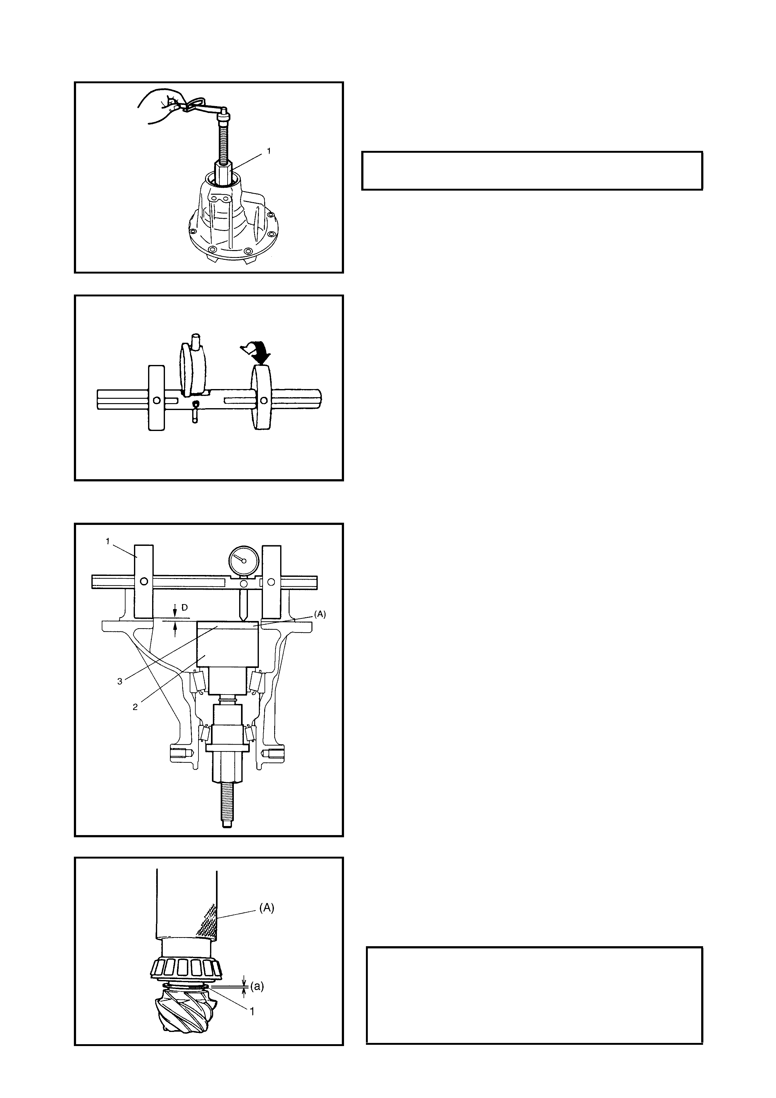
NOTE:
Before taking measurement, check rotation by
hand for more than 15 revolutions.
6. Tighten the bevel pinion nut using special tool (1) so
that the specified bearing preload is obtained.
NOTE:
• When setting the dial gauge to the bearing form
dummy with dummy sh aft, tighten the screw l ightly. Be
careful not to overtighten it, which will cause damage
to the dial gauge.
• With the dial gauge set, turn the dummy back and forth
by hand several times and attain accurate 0 (zero)
adjustment.
• It is desira ble that th e short pointe r indicates bey ond 2
mm when long one is at 0 (zero).
7. Set the dial gauge to the bearing form dummy with
dummy shaft and make 0 (zero) adjustment on the
surface plate.
8. Put the block dummy (3) on the pinion form dummy (2),
special tool
09922-76510 (A)
.
NOTE:
• Repeat turning dummy back and forth and measure
the distance of the top surface of the block dummy
accurately.
• When the dial gauge measuring tip extends from 0
(zero) position, pointer turns counter-clockwise.
• The measured value may exceed 1 mm. Therefore, it
is also necessary to know the reading of the short
pointer.
9. Place the zero-adjusted bearing form dummy with
dummy shaft (1) and dial gauge set on the block
dummy (3) and take a measurement between zero
position and extended dial gauge measuring tip.
10. Obtain adjusting shim thickness by using the measured
value of the dial gauge in the following equation.
Required Shim Thickness = Dial Gauge Measured Value D
11. Select adjusting shim(s) (1) closest to the calculated
value from among the following available sizes.
12. Fit the shim(s) and then press-fit the rear bearing with
special tool
09940-51710 (A)
.
DRIVE BEVEL PINION BEARING
PRELOAD @ 50 rpm 0.5 - 1.3 Nm
AVAILABLE SHIM THICKNESS (a)
0.30, 1.00,
1.03, 1.06,
1.09, 1.12,
1.15, 1.18,
1.21, 1.24,
1.27, 1.30 mm
NOTE:
• Use a new spacer (3) for reinstallation.
• Apply differential oil to bearings.
13. With new pinion spacer (3) inserted as shown, install
front bearing to differential carrier.
14. Install a new oil seal (1) into the differential carrier (2)
using special tool
09913-75810
(B)
and a hammer.
15. Apply grease to new oil seal lip.
(A): Lithium grease
NOTE:
• Before taking me asurement, c heck for smo oth rotation
by hand.
• Drive be vel pi nion b earing pr eloa d is ad juste d by tight-
ening the drive bevel pinon nut to deform the spacer.
Therefore, use a new spacer for adjustment and
tighten the drive bevel pinion nut step by step and
check for starting torque (preload) as often as tighten-
ing to prevent over-cr ushing of the spacer.
If preload exceeds specification given below during
adjustmen t, replace t he spacer and rep eat the preloa d
adjustment procedure. Do not decrease the starting
torque (preload) by loosening the drive bevel pinon.
• For measuring the drive bevel pinion bearing preload,
turning the drive bevel pinion at about 50 rpm is
required.
16. Install the companion flange (1) to the drive bevel
pinion and tighten the drive bevel pinion nut gradually
with special tool
09930-40113
(A). S
et the bearing
preload to specification with a torque wrench (1) and
socket with adapter (2).
DIFFERENTIAL CARRIER SEAL
INSTALLING DEPTH (a) 7.5 - 8.5 mm
DRIVE BEVEL PINION NUT TORQUE
SPECIFICATION 70 - 250 Nm
DRIVE BEVEL PINION BEARING PRE-
LOAD TORQUE SPECIFICATION 0.5 - 1.3 Nm
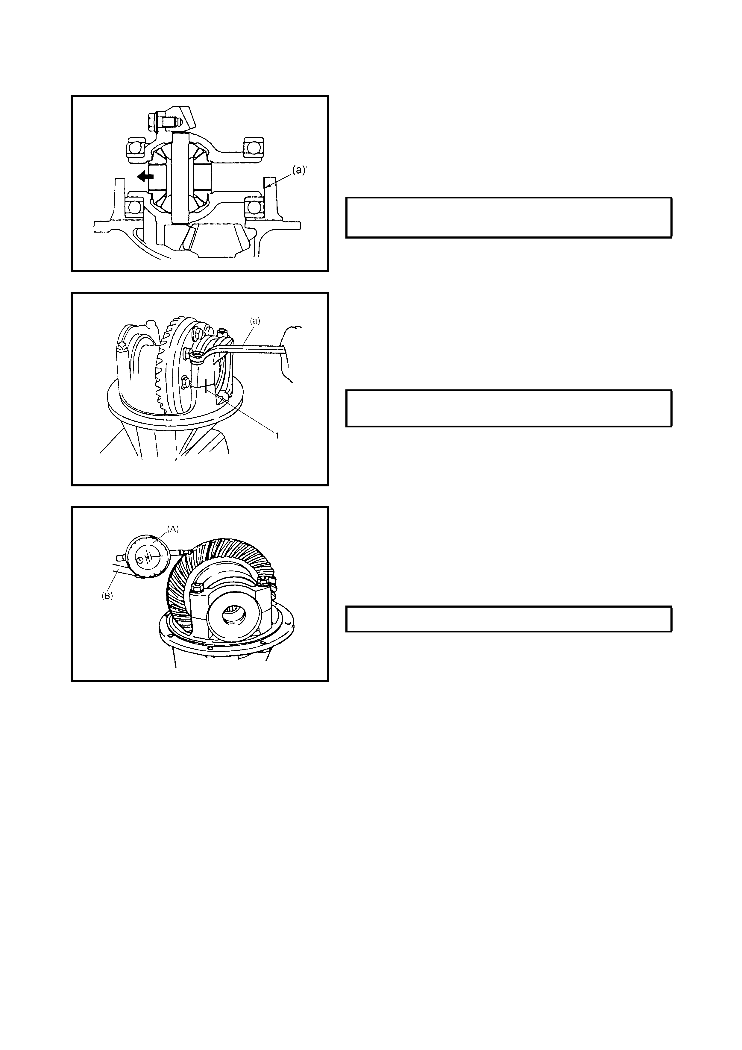
Differential Assembly
1. Place the differential gear case assembly into the dif-
ferential carrier and push the differential case to the left
side as shown.
2. Measure clearance (a) between the side bearing and
differential carrier by using a thickness gauge.
Select shims closest to measured value.
NOTE:
• Align match marks (1) on the caps and carrier.
• Apply differential gear oil to the bearings.
3. Divide selected shim(s) between both sides (right and
left) and install them to the differential carrier.
4. Install the differential side bearing caps.
NOTE:
Apply
the
measuring tip of
the
dial gauge at right
angles to
the
convex side (drive side) of
the
tooth.
5. Measure drive bevel gear backlash using special tools
09900-20607
(A)
and
09900-20701
(B)
.
If backlash is out of specification, change the division
of shims so that the backlash is within specification.
6. Check gear tooth contact as follow s.
CAUTION:
When applying red lead paste to teeth,
paint tooth surfaces uniformly. The paste must not
be too dry or too fluid.
a. After cleaning the tooth surface of the drive bevel
gear, paint the teeth with gear marking compound
evenly using a brush or sponge, etc.
NOTE:
Be careful not to turn
the
bevel gear more than
one full revolution, or it will hinder an accurate check.
b. Tu rn the gear to bring its painted part in m esh with
the bevel pinion and tur n it back and forth by hand
to repeat their contact.
c. Bring painted part up and check the contact pattern,
referring to the following chart. If the contact pattern
is not normal, readjust or replace as necessary
according to instruction in the chart.
SHIM THICKNESS AVAILABILITY
0.1, 0.3, 0.5,
0.7 mm
DIFFERENTIAL SIDE BEARING CAP
BOLT TORQUE SPECIFICATION (a) 23 Nm
DRIVE BEVEL GEAR BACKLASH 0.10 - 0.20 mm

4. After comple tion of th e gear to oth con tact check, s take
drive the bevel pinion nut (2) with staking tool (1) and
hammer.
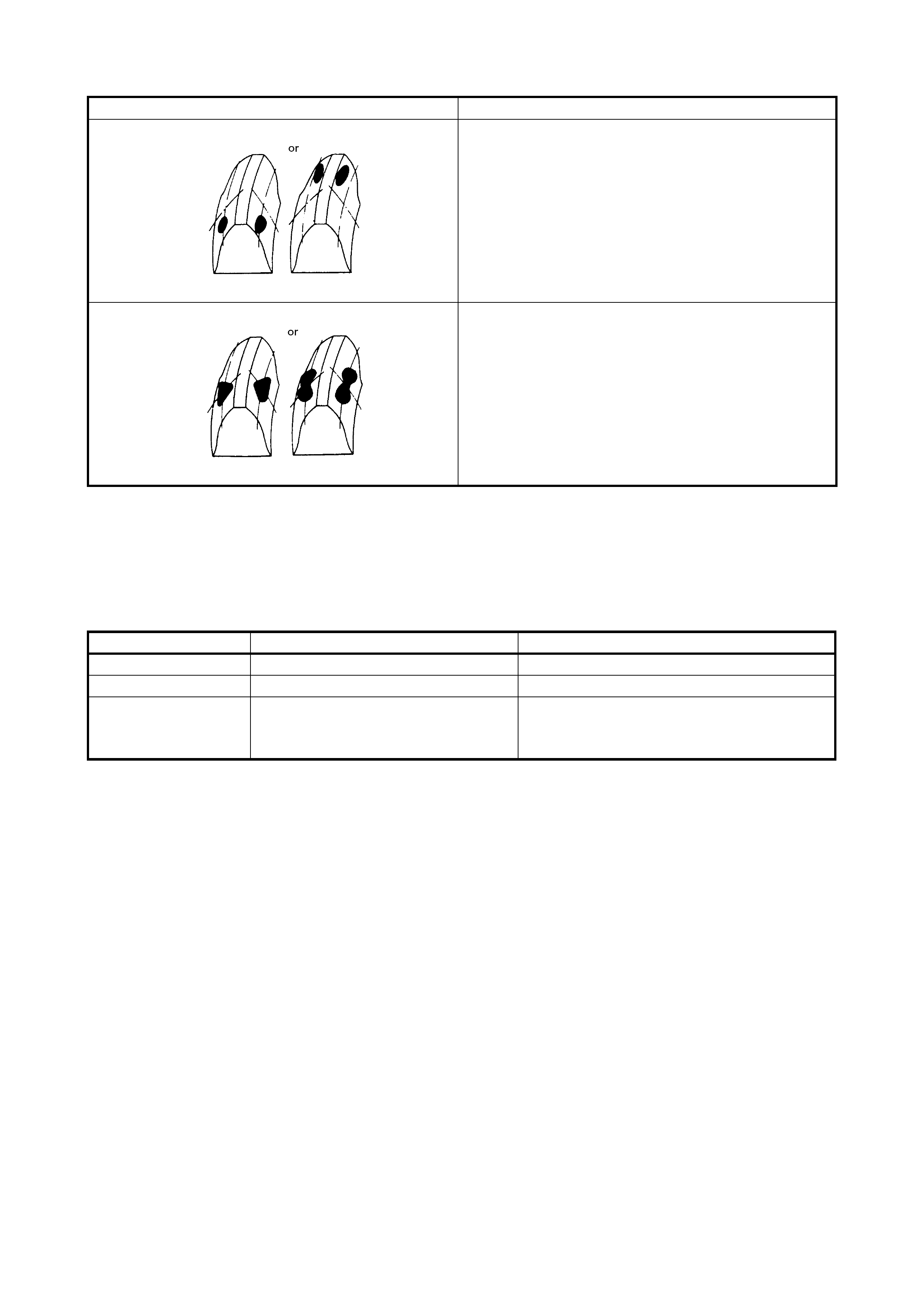
TOOTH CONTACT PATTERN DIAGNOSIS AND REMED Y
NORMAL
HIGH CONTACT
Pinion is positioned too far from the
centre of the drive bevel gear.
1) Increase thickness of pinion
height adjusting shim and posi-
tion pinion closer to gear centre.
2) Adjust drive bevel gear backlash
to specification.
LOW CONTACT
Pinion is positioned too close to the
centre of drive the bevel gear.
1) Decrease
the
thickness of pinion
height adjusting shim and posi-
tion pinion farther from gear cen-
tre.
2) Adjust drive bevel gear backlash
to specification.
These contact patterns indicate that the “offset” of dif-
ferential is too much or too little. The remedy is to
replace the carrier with a new one.
5. REQUIRED SERVICE MATERIAL
These contact patterns, located on toe or heel on both
drive and coast sides, mean that:
1. Both pinion and gear are defective,
2. Carrier is not true and square, or
3. Gear is not properly seated on differential case.
The remedy is to replace the defective member.
Irregular patterns:
If the pattern is not oval, it means that bevel gear is
defective. High or low spots on tooth surfaces or on
the seat of bevel gear are the cause of irregular pat-
terns appearing on some teeth. The remedy is to
replace the pinion and-gear set and, if the seat is
defective, so is transfer case.
TOOTH CONTACT PATTERN DIAGNOSIS AND REMED Y
Material Recommended product Use
Thread lock cement THREAD LOCK CEMENT 1322 Drive bevel gear bolts
Lithium grease Lithium grease Oil seal lips
Sealant Three Bond No. 1215 • Thread part of differential carrier bolt
• Mating surface of differential carrier
• Mating surface of rear axle housing
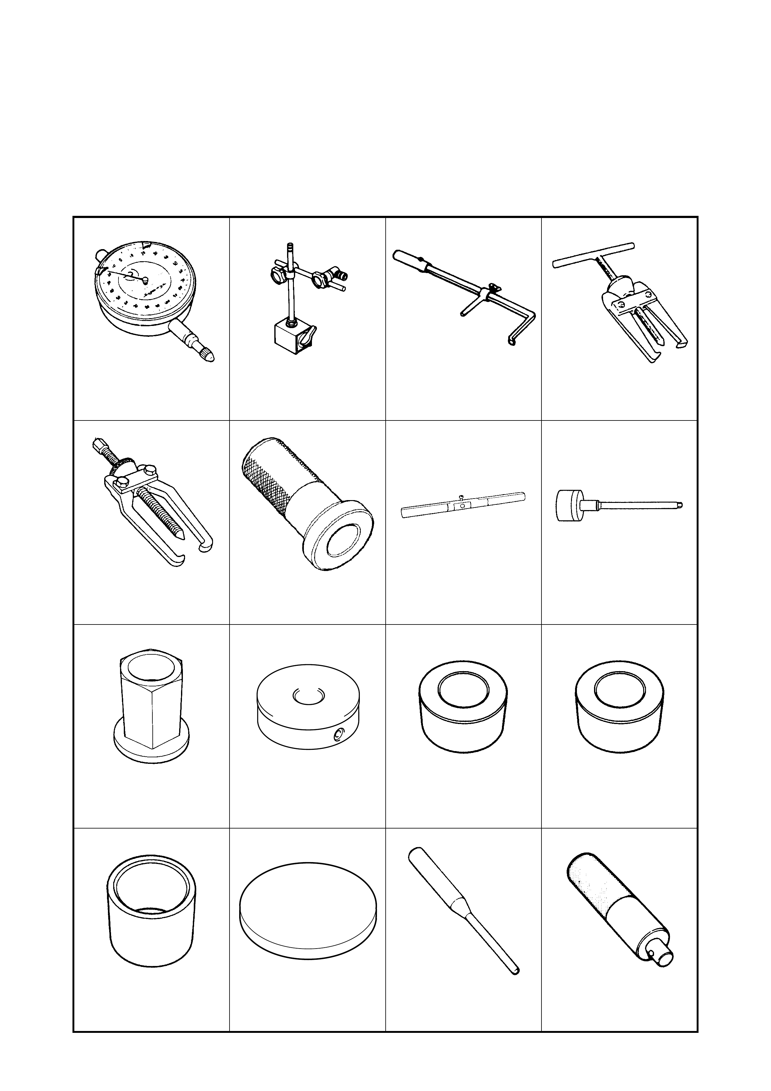
6. SPECIAL TOOLS
NOTE: Refer to Section 0A GENERAL INFORMATION – 7. CONSOLIDATED TOOLS for a detailed list of
special tools and the local equivalent if one is available.
09900-20607 09900-20701 09913-50121 09913-60910
Dial gauge Magnetic stand Oil seal remover Bearing puller
09913-65135 09913-75810 09922-76120 09922-76140
Bearing puller Bearing installer Dummy shaft Bevel pinion shaft
09922-76150 09922-76230 09922-76320 09922-76340
Bevel pinion nut Bevel gear dummy Rear collar Rear collar
09922-76410 09922-76510 09922-85811 09924-74510
Front collar Gauge block Spring pin remover Bearing installer handle
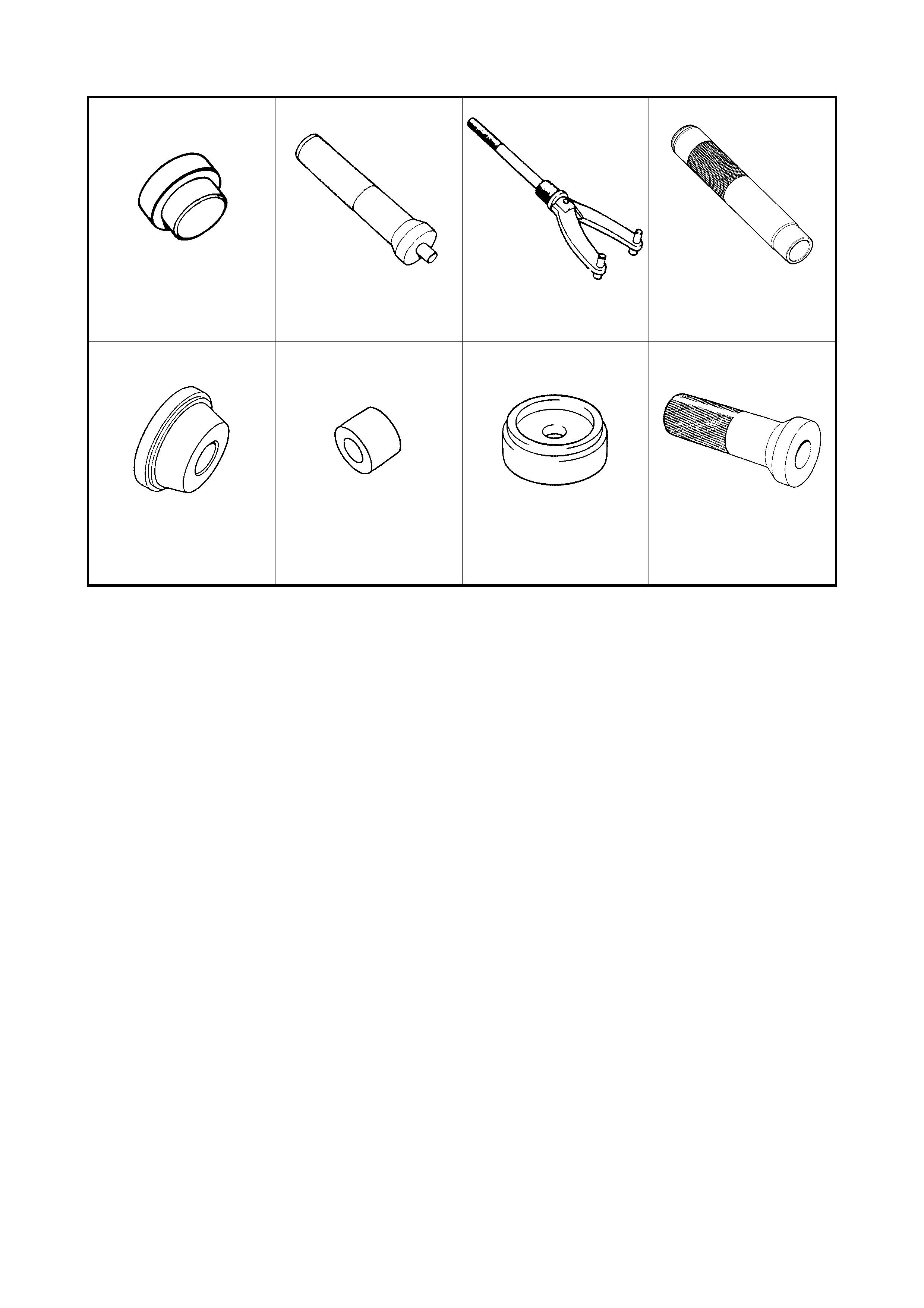
09925-88210 09925-98210 09930-40113 09940-51710
Beari ng puller attachment Beari ng installer Flange hol der Beari ng installe r
09941-34513-004 09951-16060 09951-16090 09951-76010
Beari ng ins talle r Lower arm bush rem ov er Oil seal ins talle r Beari ng ins talle r