
SECTION 8 - BODY ELECTRICAL SYSTEM
1. DIAGNOSIS
1.1 HEADLIGHT
1.2 TURN SIGNAL AND HAZARD WARNING
LIGHTS
1.3 CLEARANCE, TAIL AND LICENCE
PLATE LIGHT
1.4 BACK-UP LIGHT
1.5 BRAKE LIGHT
1.6 FRONT FOG LIGHT
1.7 SPEEDOMETER AND VSS
1.8 FUEL GAUGE AND FUEL LEVEL
SENSOR (GAUGE UNIT)
1.9 ENGINE COOLANT TEMPERAT URE
(ECT) GAUGE AND ECT SENSOR
1.10 ENGINE OIL PRESSURE WARNING
LIGHT
1.11 BRAKE AND PARKING BRAKE
WARNING LIGHT
1.12 REAR WINDOW DEFOGGER
1.13 FRONT & REAR WIPERS AND
WASHERS
1.14 POWER WINDOW CONTROL SYSTEM
1.15 CIGARETTE LIGHTER
1.16 POWER DOOR LOCK SYSTEM WITH
KEYLESS ENTRY SYSTEM
1.17 POWER DOOR MIRROR CONTROL
SYSTEM
1.18 INTERIOR LIGHT
1.19 HORN
1.20 IGNITION KEY REMINDER AND LIGHT
REMINDER WARNING BUZZER
1.21 SEAT BELT WARNING LIGHT
2. ON-VEHICLE SERVICE
2.1 CAUTIONS IN SERVICING
2.2 HEADLIGHT AND POSITION LIGHT
Headlight and Position Light Switch
Headlight Assembly
Headlight Bulb
Position Light Bulb
Headlight Aiming Adjustment with
Screen
2.3 TURN SIGNAL AND HAZARD WARNING
LIGHTS
Turn Signal and Hazard Warning
Lights System Circuit
Turn Signal and Hazard Warning
Lights System Circuit Check
Turn Signal Switch
Front Turn Signal Assembly
Front Turn Signal Bulb
Front Fender Turn Signal Assembly
Front Fender Turn Signal Bulb
Rear Turn Signal Assembly
Rear Turn Signal Bulb
Turn Signal and Hazard Relay
Hazard Switch
2.4 FRONT FOG LIGHTS
Front Fog Light Switch
Front Fog Light
Front Fog Light Bulb
Front Fog Light Aiming Adjustment
with Screen
WARNING:
For vehicles equipped with Supplement Restraint (Airbag) System
• Service on and around the airbag system components or wiring must be performed only by
an authorised HOLDEN retailer. Refer to Section 10B AIRBAG SYSTEM COMPONENTS AND
WIRING LOCATION VIEW in GENERAL DESCRIPTION in order to confirm whether you are
performing service on or near the airbag system components or wiring. Please observe all
W ARNINGS and SERVICE PRECAUTIONS, refer to Section 10B ON-VEHICLE SERVICE before
performing service on or around the airbag system components or wiring. Failure to follow
WARNINGS could result in unintentional activation of the system or c ould render the system
inoperative. Either or these two condit ions may result in severe inju ry.
• Technical service work must not be started for at least 90 sec onds after the ignition s witch is
turned to the “LOCK” position and the negative cable is disconnected from the battery.
Otherwise, the system may be activated by reserve energy in the Sensing and Diagnostic
Module (SDM).

2.5 BRAKE AND TAIL LIGHT
Brake Light Switch
Tail Light Switch
Brake and Tail Light Assembly
Brake and Tail Light Bulb
High Mount Brake Light Assembly
High Mount Brake Light Bulb
2.6 BACKUP LIGHT
Backup Light Switch (M/T)
Transmission Range Sensor (Shift
Switch) (A/T)
Backup Light Assembly
Backup Light Bulb
2.7 LICENCE PLATE LIGHT
Licence Plate Light Switch
Licence Plate Light Assembly
Licence Plate Light Bulb
2.8 ILLUMINATION CONTROLLER
Inspection
2.9 IGNITION SWITCH
On-vehicle Inspection
Removal
Installation
2.10 COMBINATION METER
Removal
Installation
Inspection
2.11 FUEL GAUGE AND FUEL LEVEL
SENSOR (GAUGE UNIT)
Fuel Gauge
Fuel Level Sensor (Gauge Unit)
Inspection
2.12 SPEEDOMETER AND VEHICLE SPEED
SENSOR (VSS)
Vehicle Speed Sensor (VSS)
2.13 ENGINE COOLANT TEMPERATURE
(ECT) GAUGE AND SENSOR
Engine Coolant Temperature (ECT)
Gauge
ECT Sensor
2.14 ENGINE OIL PRESSURE WARNING
LIGHT
Engine Oil Pressure Switch
2.15 BRAKE SYSTEM WARNING LIGHT
(PARKING BRAKE INDICATOR, BRAKE
FLUID WARNING AND EBD SYSTEM
WARNING LIGHT)
Brake Fluid Level Switch
Parking Brake Switch
2.16 REAR WINDOW DEFOGGER
Defogger Switch
Defogger Wire
2.17 WIPERS AND WASHERS
Components
Front Wiper and Washer Switch
Front Wiper Motor
Washer Tank and Washer Pump
Rear Wiper and Washer Switch
Rear Wiper Motor
2.18 IGNITION KEY REMINDER AND LIGHT
REMINDER WARNING BUZZER
Removal
Installation
2.19 POWER WINDOW CONTROL SYSTEM
Power Window Main Switch
Power Window Sub Switch
2.20 DOOR SWITCH
Inspection
2.21 POWER DOOR LOCK SYSTEM WITH
KEYLESS ENTRY SYSTEM
Component Location
System Description
Change of Signal Mode
Power Door Lock System Operation
Power Door Lock System Circuit
Power Door Lock Vehicle Operation
Power Door Lock System Circuit
Check
Driver’s Door Knob Switch
Door Lock Actuator
Keyless Entry System Operation
Keyless Entry System Circuit
Keyless Entry System Circuit Check
Transmitter
Code Registration Procedure
2.22 POWER DOOR MIRROR CONTROL
SYSTEM
Mirror Switch
2.23 DOOR MIRROR ACTUATOR
Removal
Inspection
Installation
2.24 MULTI INFORMATION DISPLAY
Removal
Inspection
Installation

1. DIAGNOSIS
1.1 HEADLIGHT
1.2 TURN SIGNAL AND HAZARD WARNING LIGHTS
1.3 CLEARANCE, TAIL AND LICENCE PLATE LIGHT
Condition Possible Cause Correction
Headlights do not
illuminate
Lighting or dimmer switch faulty. Check headlight switch.
HEADLIGHT R and L fuses (15A) in main fuse
box blown. Replace fuse to check for short.
Wiring or grounding faulty. Repair circuit .
One he ad light does
not illum inate
Bulb blown. Replace bulb.
HEADLIGHT R or L fuse (15A) in main fuse
box blown. Replace fuse to check for short.
Wiring or grounding faulty. Repair circuit .
One be am (Hi or Lo)
does no t illu mi na te
Bulb blown. Replace bulb.
Lighting or dimmer switch faulty. Check switch.
Wiring or grounding faulty. Repair circuit .
Condition Possible Cause Correction
Flash rate high or
only one si de flashe s
Bulb blown on ‘flash rate high’ - side Replace bulb.
Incorrect bulb. Replace bulb.
Turn signal and hazard warning relay faulty. Check system, refer to 2.3 TURN
SIGNAL AND HAZARD
WARNING LIGHTS SYSTEM in
this Section.
Wiring or grounding faulty
Flas h rate low
Supply voltage low Check charging system
Turn signal and hazard warning relay faulty Check system, refer to 2.3 TURN
SIGNAL AND HAZARD
WARNING LIGHTS SYSTEM in
this Section.
One si de o nly
flashes
Turn signal switch faulty Check system, refer to 2.3 TURN
SIGNAL AND HAZARD
WARNING LIGHTS SYSTEM in
this Section.
Turn signal and hazard warning relay faulty
Wiring or grounding faulty
No flashing
HORN fuse (15A) and/or METER fuse(s)
blown. After checking for short circuit,
replace MSTER fuse.
Turn signal and hazard relay faulty. Check system, refer to 2.3 TURN
SIGNAL AND HAZARD
WARNING LIGHTS SYSTEM in
this Section.
Combination switch or hazard switch faulty.
Wiring or grounding faulty.
Condition Possible Cause Correction
All lights do not illu-
minate
TAlL fuse blown. Replace fuse to check for short.
Combination switch (lighting and dimmer
switch) faulty. Check switch.
Wiring or grounding faulty. Repair circuit .
Some lights do not
illuminate
Bulb(s) blown. Replace bulb(s).
Wiring or grounding faulty. Repair circuit .

1.4 BACK-UP LIGHT
1.5 BRAKE LIGHT
1.6 FRONT FOG LIGHT
1.7 SPEEDOMETER AND VSS
1.8 FUEL GAUGE AND FUEL LEVE L SENSOR (GAUGE UNIT)
1.9 ENGINE COOLANT TEMPERATURE (ECT) GAUGE AND ECT SENSOR
Condition Possible Cause Correction
Back-u p lig hts do
not illum inate
Bulb(s) blown. Replace bulb(s).
BACK fuse blown. Replace fuse to check for short.
Back-up light switch or transmission range
sensor (shift) switch faulty. Check or rep lace.
Wiring or grounding faulty. Repair circuit .
Back-up lights stay
on
Back- up light swi tc h fault y or trans mi ssio n
range sensor (shift) switch faulty. Check or rep lace.
Conditio n Pos sibl e Ca us e Correcti on
Brake lights do not
illuminate
Bulb(s) blown. Replace bulb(s).
STOP fuse blown. Replace fuse to check for short.
Brake light switch faulty. Check switch.
Wiring or grounding faulty. Repair circuit.
Brake lights stay on
Brake light switch faulty. Check, adjust or replace switch.
Conditio n Pos sibl e Ca us e Correcti on
Front fog lights do
not illum inate
Front fog light switch faulty. Check front fog light switch.
TAIL fuse (15A) in circuit fuse box blown. Replace fuse to check for short.
Front fog light relay faulty. Check relay.
Wiring or grounding faulty. Repair circuit.
One lig ht do es not
illuminate
Bulb blown. Replace bulb.
Wiring or grounding faulty. Repair circuit.
Conditio n Pos sibl e Ca us e Correcti on
Speedomet er shows
no operation or
incorrect operation
METER and/or RADIO.DOME fuse(s) blown. Replace fuse(s) to check for short.
VSS faulty. Check VSS.
Printed plate in combination meter faulty. Check printed plate.
Wiring or grounding faulty. Repair circuit.
Signal rotor on differential case faulty. Check signal rotor.
Speedometer faulty. Check speedometer.
Condition Possible Cause Correction
Fuel ga uge show s
no opera tion or
incorrect operation
METER fuse blown. Replace fuse to check for short.
Fuel gauge unit faulty. Check fuel gauge unit.
Printed plate in combination meter faulty. Check printed plate.
Fuel gauge faulty. Check fuel gauge.
Wiring or grounding faulty. Repair circuit.
Conditio n Pos sibl e Ca us e Correcti on
Engine coolant
temp. gauge shows
no operation or
incorrect operation
METER fuse blown. Replace fuse to check for short.
ECT gauge faulty. Check ECT gauge.
Printed plate in combination meter faulty. Check printed plate.
ECT sensor faulty. Check ECT sensor.
Wiring or grounding faulty. Repair circuit.

1.10 ENGINE OIL PRES SURE WARNING LIGHT
1.11 BRAKE AND PARKIN G BRA KE WARN ING LIGHT
1.12 REAR WINDOW DEFOGGER
1.13 FRONT & REAR WIPERS AND WASHERS
Conditio n Pos sibl e Ca us e Correcti on
Engine oil pressure
warning light does
not illum inate when
the ignition switch is
turned to ON posi-
tion w ith engine off
Bulb in combination meter blown. Replace bulb.
METER fuse blown. Replace fuse to check for short.
Printed plate in combination meter faulty. Check printed plate.
Oil pressure switch faulty. Check oil pressure switch.
Wiring or grounding faulty. Repair circuit.
Engine oil pressure
warnin g light stays
on
Oil pressure switch faulty. Check oil pressure switch.
Conditio n Pos sibl e Ca us e Correcti on
Brake warning light
does no t illu mi na te
(when fluid level low,
parking brake pulled
up and/or EBD sys-
tem faulty)
Bulb in combination meter blown. Replace bulb.
Printed plate in combination meter faulty. Check printed plate.
METER fuse blown. Replace fuse to check for short.
Brake fluid level switch faulty. Check brake fluid level switch.
Parking brake switch faulty. Check parking brake switch.
ABS control module faulty. Check ABS control module.
Wiring or grounding faulty. Repair circuit.
Brake warning light
does no t illu mi na te
when cranking (igni-
tion swi tch t urned to
ST position)
Ignition switch faulty. Check ignition switch.
Printed plate in combination meter faulty. Check printed plate.
Wiring or grounding faulty. Repair circuit.
Brake system warn-
ing light stays on
Brake fluid level switch, parking brake switch
and/or ABS control module faulty. Check switch.
Electrical circuit shorted to ground. Repair circuit.
Condition Possible Cause Correction
Defogger does not
operate
REAR DEFG fuse blown. Replace fuse to check for short.
Defogger wire faulty. Repair defogger wire.
Rear window defogger switch faulty. Check switch.
Wiring or grounding faulty. Repair circuit.
Condition Possible Cause Correction
Wiper malfunctions
WIPER.WASHER fuse blown. Replace fuse to check for short.
Wiper motor faulty. Check wiper motor.
Combination switch (wiper switch) faulty. Check wiper switch.
Wiring or grounding faulty. Repair circuit.
Washer malfunc-
tions
W asher hose or nozzle clogged. Clean or repair clogged hose or
nozzle.
WIPER.WASHER fuse blown. Replace fuse to check for short.
Washer pump faulty. Check washer pump.
Rear wiper relay faulty. Check wiper relay.
Combination switch (wiper switch) faulty Check wiper switch.
Wiring or grounding faulty. Repair circuit.

1.14 POWER WINDOW CONTROL SYSTEM
1.15 CIGARETTE LIGHTER
1.16 POWER DOOR LOCK SYS TEM WITH KEYLES S EN TRY SYSTEM
Conditio n Pos sibl e Ca us e Correcti on
All power windows
do not operate
POWER WINDOW fuse blown. Replace fuse to check for short.
Ignition switch faulty. Check ignition switch.
Power window main switch faulty. Check power window main switch.
Wiring or grounding faulty. Repair circuit.
One power window
does not operate
Wiring and/or connector faulty. Check wiring and/or connector.
Power window switch (main or sub) faulty. Check power window switch.
Window actuator faulty. Check window actuator.
Grounding faulty. Repair.
Condition Possible Cause Correction
Cigarette lighter
shows no operation
CIGAR fuse blown. Replace fuse to check for short.
Ignition switch faulty. Check ignition switch.
Cigarette lighter faulty. Check cigarette lighter.
Wiring or grounding faulty. Repair circuit.
Conditio n Possible Ca us e Correcti on
All the doors are not
locked/unlocked by
the drivers side door
key switch
DOOR LOCK fuse blown. After checking for short circuit,
replace fuse.
Drivers side door knob switch faulty Check system, refer to 2.21
POWER D OOR LOCK SYSTEM
WITH KEYLESS ENTRY SYSTEM
in this Section.
Power door lock controller faulty
Wiring or grounding faulty.
Only one door is not
locked/unlocked
Power door lock actuator faulty Check system, refer to 2.21
POWER D OOR LOCK SYSTEM
WITH KEYLESS ENTRY SYSTEM
in this Section.
Wiring or grounding faulty
All doo rs are not
locked/unlocked by
keyless entry trans-
mitter
Transmitter battery dead Replace battery.
Transmitter faulty Replace transmitter
Code registration error Perform code registration
Door switch faulty Check system, refer to 2.21
POWER D OOR LOCK SYSTEM
WITH KEYLESS ENTRY SYSTEM
in this Section
Key remainder switch (in ignition switch) faulty
Power door lock controller faulty
Wiring or grounding faulty
Turn signal lights are
not flashed when
doors are locked/
unlocked by trans-
mitter
Keyless entry system is in interior light signal
mode Change signal mode, refer to 2.21
POWER D OOR LOCK SYSTEM
WITH KEYLESS ENTRY SYSTEM
— CHANGE OF S IGNAL MODE in
this Section.
Turn signal and hazard warning system faulty Check system, refer to 2.3 TURN
SIGNAL AND HAZARD WARNING
LIGHTS in this Section
Power door lock controller faulty
Wiring or grounding faulty
Interior light does not
turn ON when interior
light switch is at
DOOR position and
doors are unlocked
by transmitter
Power door lock controller faulty Check system, refer to 2.21
POWER D OOR LOCK SYSTEM
WITH KEYLESS ENTRY SYSTEM
in this Section
Wiring or grounding faulty

1.17 POWER DOOR MIRROR CONTROL SYSTEM
1.18 INTERIOR LIGHT
1.19 HOR N
1.20 IGNITION KEY REMINDER AND LIGHT REMINDER WARNING BUZZER
1.21 SEAT BELT WARNING LIGHT
Conditio n Pos sibl e Ca us e Correcti on
All power mirrors do
not operate
CIGAR fuse blown. Replace fuse to check for short.
Power door mirror switch faulty. Check switch.
Wiring or grounding faulty. Repair circuit.
One power mirror
does not operate
Power door mirror switch faulty. Check switch.
Actuator (power door mirror motor) faulty. Check actuator.
Wiring or grounding faulty. Repair circuit.
Conditio n Pos sibl e Ca us e Correcti on
Interior lights do not
illuminate
Bulbs blown. Replace bulb s.
RADIO.DOME fuse blown. Replace fuse to check for short.
Interior light switch faulty. Check switch.
Door switch faulty. Check switch.
Wiring or grounding. Repair circuit.
One int eri or lig ht
does no t illu mi na te
Bulb blown. Replace bulb.
Interior light switch faulty. Check switch.
Door switch faulty. Check switch.
Wiring or grounding. Repair circuit.
Conditio n Pos sibl e Ca us e Correcti on
Horn does not ope r-
ate
HORN.HAZARD fuse blown. Replace fuse to check for short.
Horn switch faulty. Check horn switch.
Horn relay faulty. Check horn relay.
Horn faulty. Replace horn.
Conditio n Pos sibl e Ca us e Correcti on
Ignition key
reminder and light
reminder warning
buzzer does not
sound
Buzzer faul ty. Replace buz zer.
Wiring or grounding faulty. Repair circuit.
Driver side door switch faulty. Check door switch.
Ignition switch faulty. Check ignition switch.
Conditio n Pos sibl e Ca us e Correcti on
Seat belt warning
light does not illumi-
nate
Bulb in combination me ter blown. Replace bulb.
METER fuse blown. Replace fuse to check for short.
Seat bel t switch faulty. Check se at belt switch.
Wiring or grounding faulty. Repair circuit.
2. ON-VEHICLE SERVICE
2.1 CAUTIONS IN SERVICING
When performing work related to electrical systems, observe the cautions described in Section 0A, GENERAL
INFORMATION for the purpose of protection of electrical parts and prevention of a fire.
2.2 HEADLIGHT AND POSITION LIGHT
HEADLIGHT AND POSITION LIGHT SWITCH
Removal and Installation
Refer to 3.5 CONTACT COIL AND COMBINATION SWITCH ASSEMBLY in Section 3C.
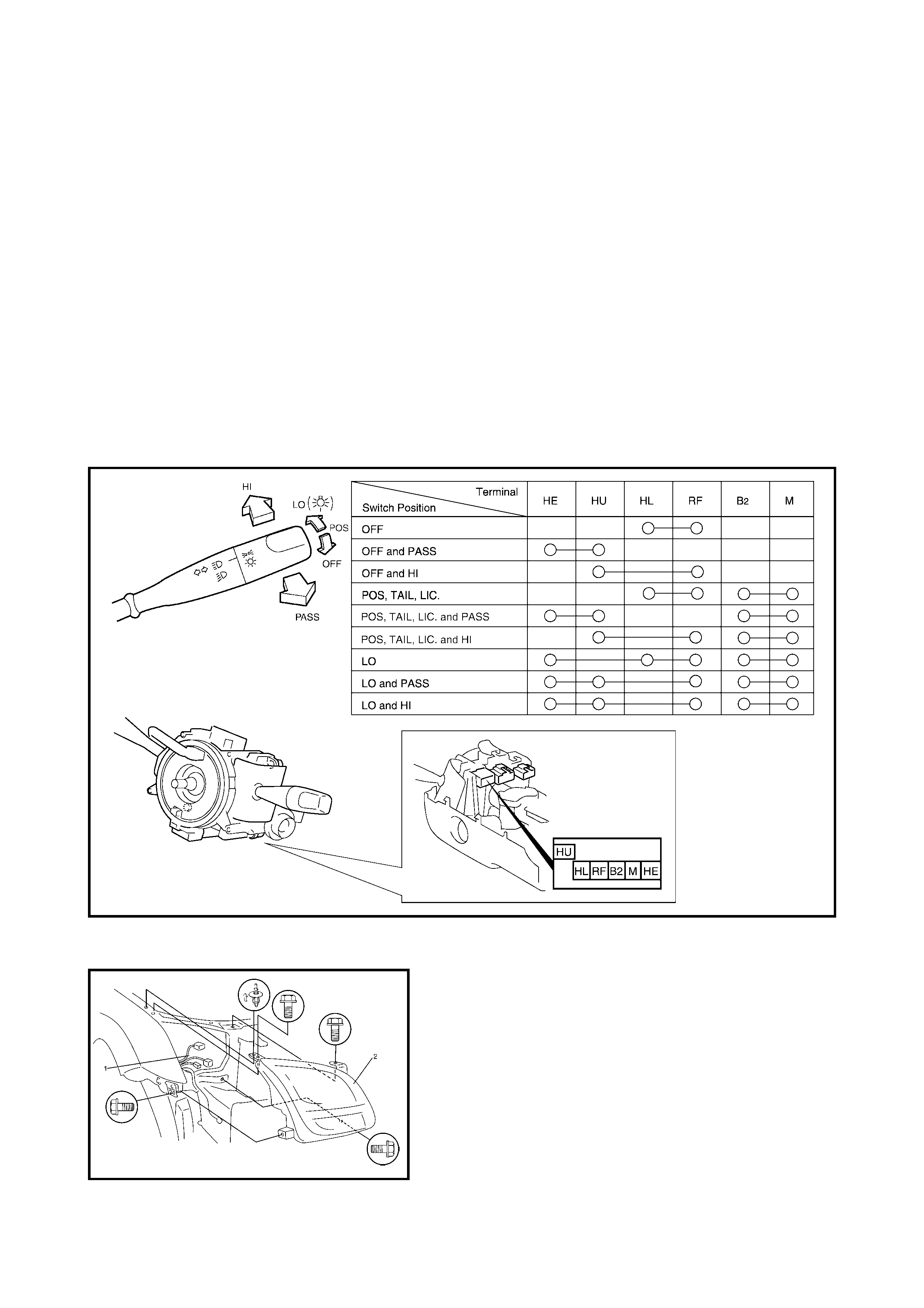
Inspection
Check for conti nuity between the termi nals at ea ch switc h position a s shown b elow. If the check r esult i s not
as sp ecified, replace the switch.
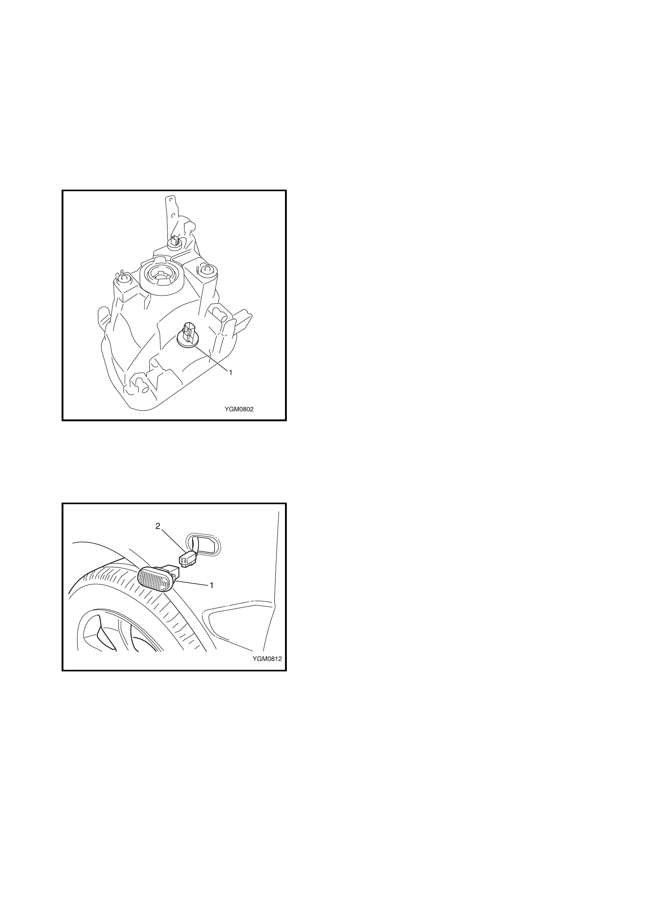
HEADLIGHT ASSEMBLY
Removal
1. Disconnect the negative cable at battery.
2. Remove the front bumper. Refer to 2.12 FRONT
BUMPER in Section 9.
3. Remove the headlight mounting bolts and clip.
4. Detach the headlight assembly (1) from the vehicle.
5. Disconnect the connectors (2) from the headlight
assembly.
Installation
Reverse removal procedure for installation.
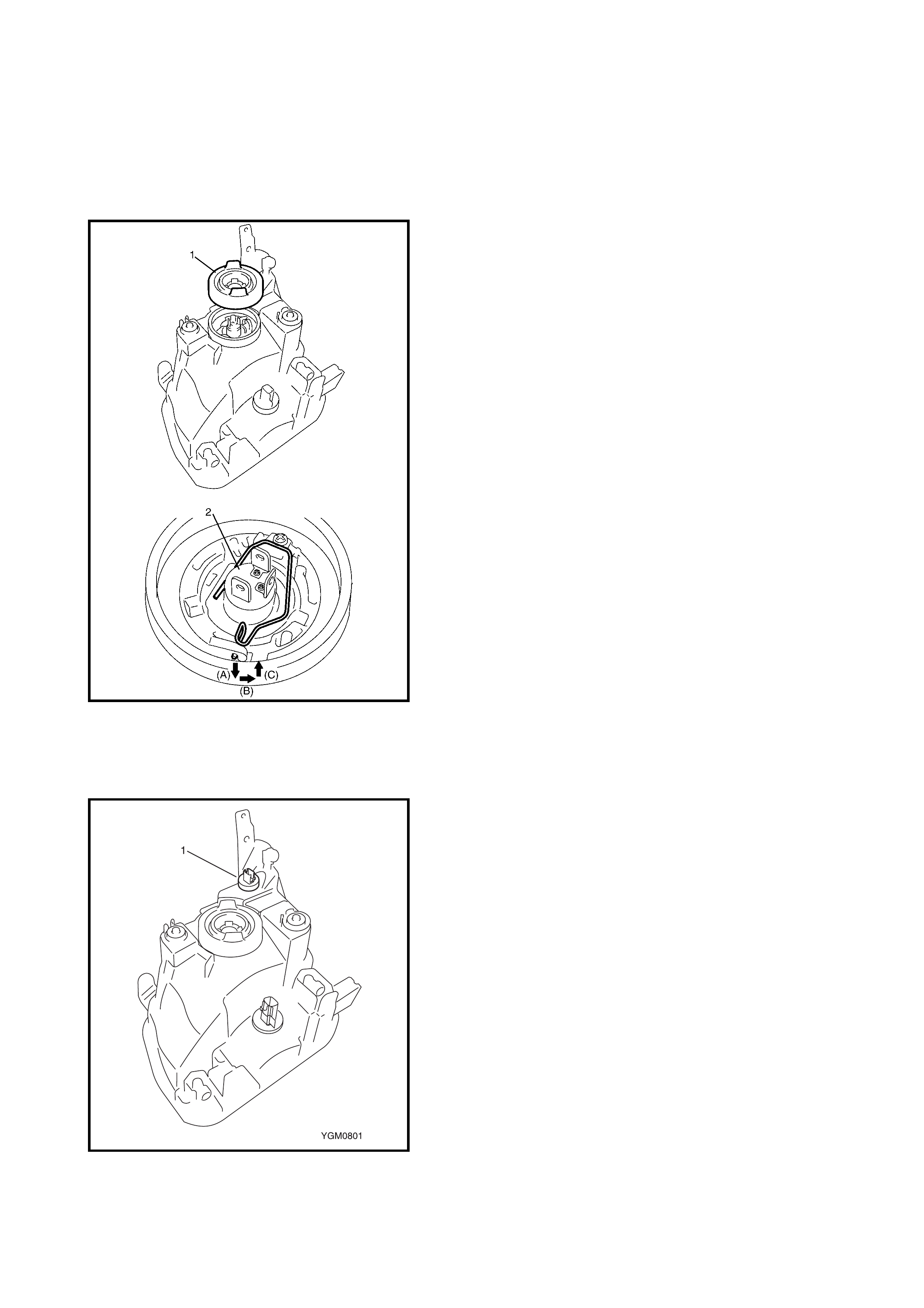
HEADLIGHT BULB
Replacement
WARNING:
• To avoid being burned, don't touch the bulb when
hot.
• Do not touch headlight bulb glass surface.
1. Disconnect negative cable at battery.
2. If required, remove the headlight assembly, refer to
HEADLIGHT ASSEMBLY in this Section.
3. Disconnect the connector from the bulb.
4. Remove the headlight socket cover (1) and replace the
bulb (2) by unhooking the retainer (A, B, C).
5. Remove the position light socket (3) by twisting 90°
anti clockwise and replace the bulb.
6. Reassemble all removed parts.
POSITION LIGHT BULB
Replacement
WARNING: To avoid being burned, don't touch t he bulb
when hot.
1. Disconnect negative cable at battery.
2. Disconnect the connector from the bulb.
3. Remove the position light socket (1) by twisting 90°
anti clockwise.
4. Replace the bulb.
5. Reassemble removed parts.
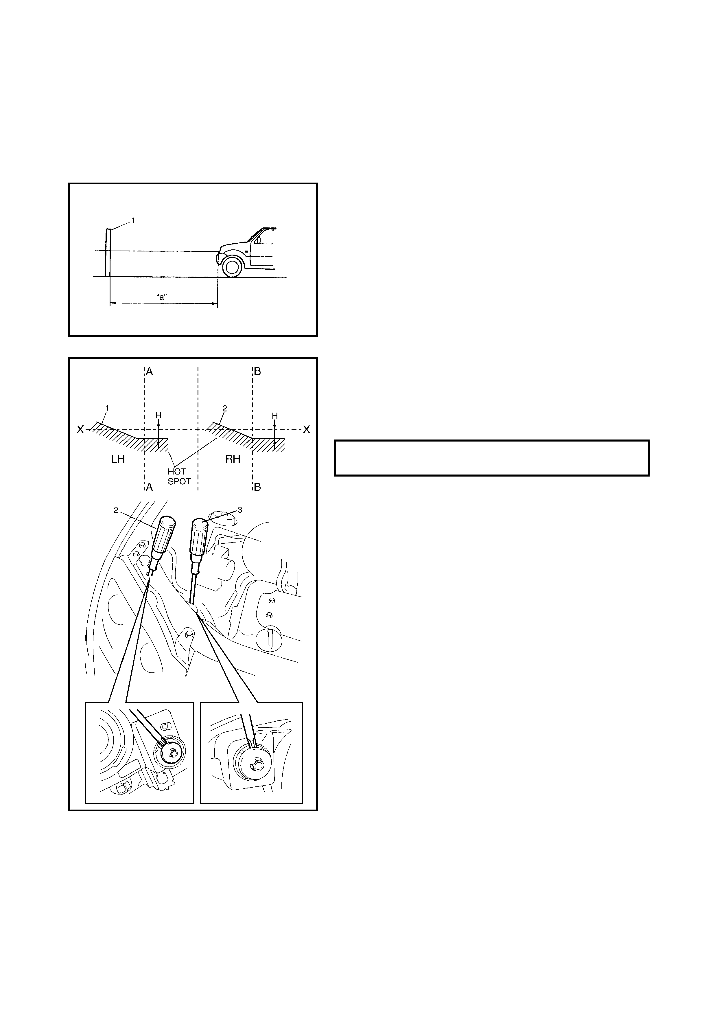
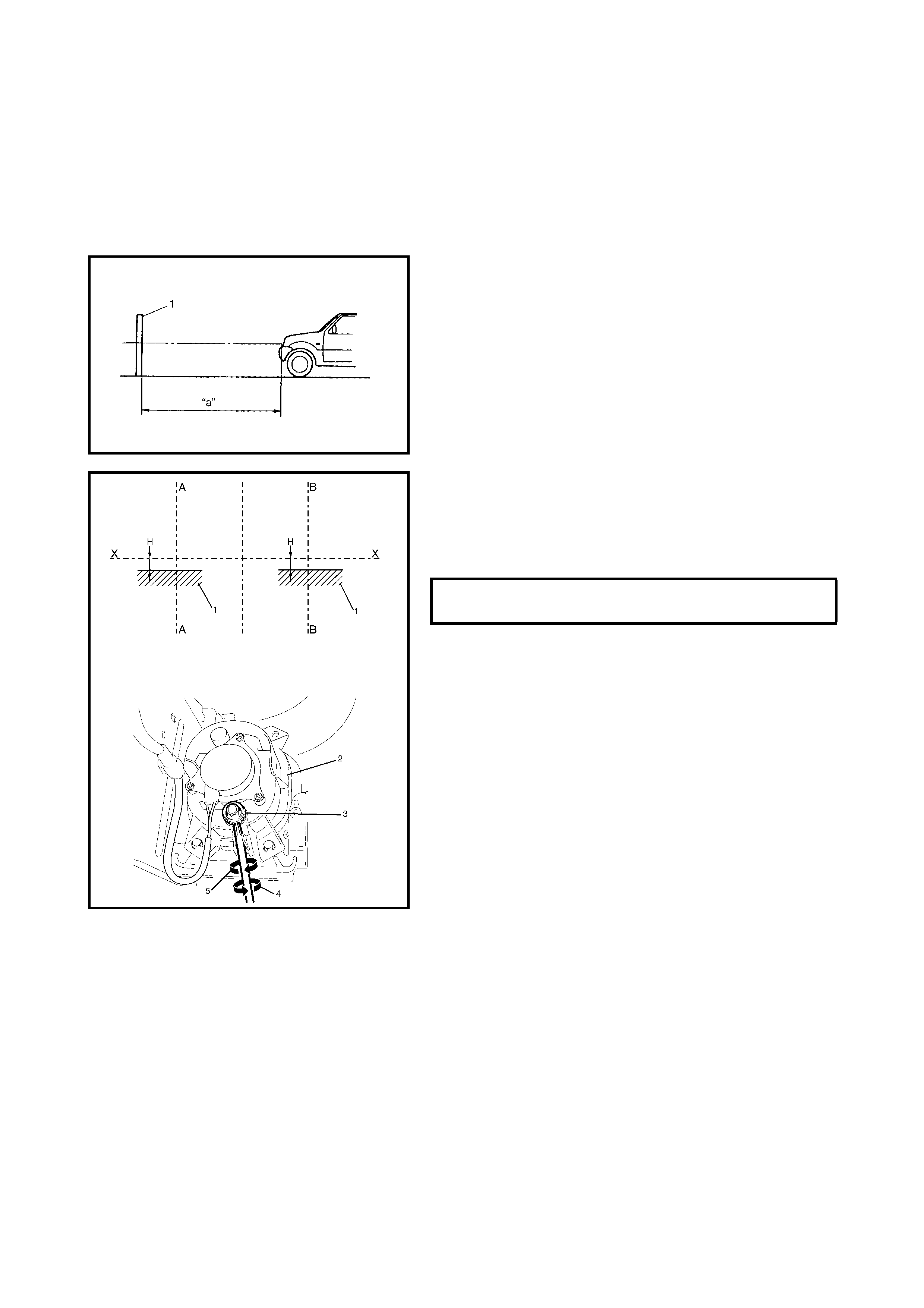
HEADLIGHT AIMING ADJUSTMENT WITH
SCREEN
NOTE:
• Unless otherwise obligated by local regulations, adjust
the headlight aiming according to following procedure.
• After replacing a headlight, always check and adjust
aiming as required.
1. Make sure the following items:
• Place the vehicle on a flat surface in front of blank wall
(screen) (1) 10 m (a) ahead of the headlights.
• Adjust the tyre air pressure the specified value, refer to
the vehicle tyre placard or owner’s manual.
• Bounce vehicle up and down by hand to stabilise sus-
pension.
• Have one person weighing approx. 75 kg seated in the
driver’s seat.
2. Turn the headlights ON to low beam.
3. Check to see if the cut line (1) and axis of each beam
hot spot (high intensity zone) aligns on the screen with
each vertical headlight centreline (A-A, B-B) and the
specified distance (H) below the headlight horizontal
centreline (X).
4. If required, align headlight to specification by adjusting
aiming gear with a screwdriver (3) for vertical adjust-
ment and/or (2) for horizontal adjustment.
LOW BEAM HOT SPOT
SPECIFICATION: H Approx. 130 mm

2.3 TURN SIGNAL AND HAZARD WARNING LIGHTS
TURN SIGNAL AND HAZARD WARNING LIGHTS
SYSTEM CIRCUIT
Inspection
1. Disconnect negative (–) cable from the battery
2. Disconnect the turn signal and hazard warning relay
connector G42 (1) from above the fusebox (2).
3. Connect negative (–) cable to battery.
4. Confirm that the right or left side turn signal lights turn
on when terminal G42-4 (1) is connected to terminal
G42-2 or G42-3 with a service wire.
If the turn s ignal light doe s not turn on, che ck the bulb
or repair the applicable circuit.
5. Check that the voltage and continuity between the
following terminals on connector G42 (1) and body
ground are within specification under each condition.
If the ch eck resul t is not as sp ecified, r epair applic able
circuit.
If the check result is OK, replace turn signal and
hazard warning relay and recheck.
TURN SIGNAL AND HAZARD WARNING LIGHTS SYSTEM CIRCUIT CHECK
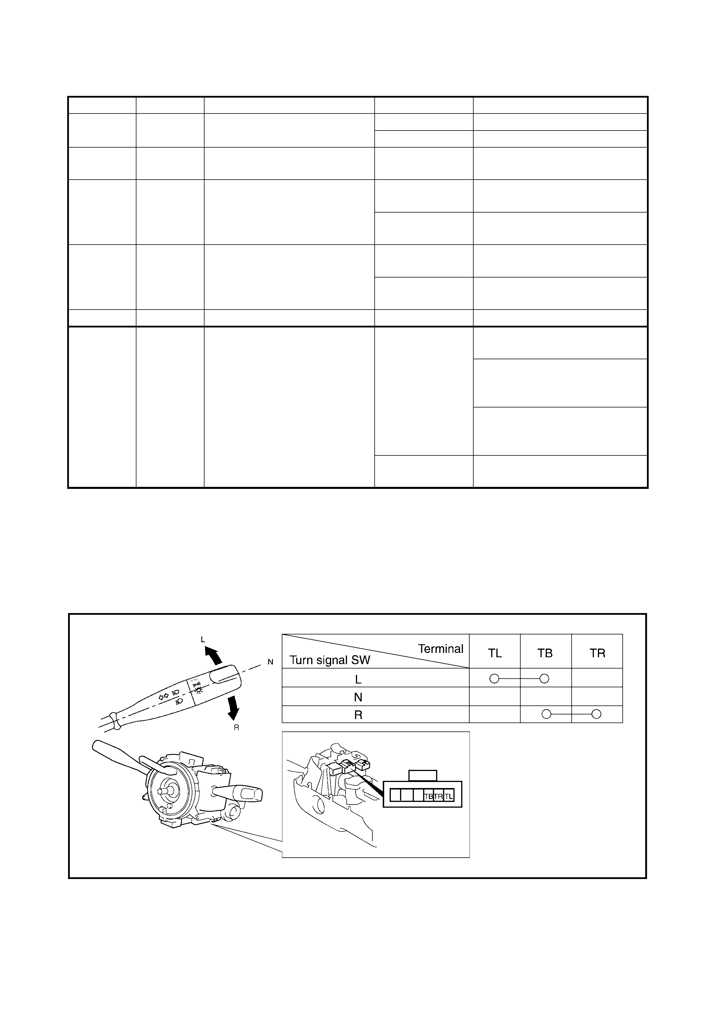
TURN SIGNAL SWITCH
Removal and Installation
Refer to 3.5 CONTACT COIL AND COMBINATION SWITCH ASSEMBLY in Section 3C.
Inspection
Check fo r continuity between the terminals at each swit ch position as shown below. If check result is not as
specified, replace the switch.
.
Terminal Wire Circuit Specification Condition
G42-1 BLU‘ Ignition switch circuit 10 — 14 V Ignition switch is in ON position
0 — 1 V Ignition switch is in ON position
G42-4 GRN/WHT Power supply for turn signal
and hazard warning lights 10 — 14 V —
G42-5 BLU/RED Right side turn signal light
switch circuit
Continuity Turn signal light switch is in R
position
No continuity Turn signal light switch is in N
or L position
G42-6 GRN/YEL Left side turn signal light
switch circuit
Continuity Turn signal light switch is in L
position
No continuity Turn signal light switch is in N
or R position
G42-7 BLK Ground 0 — 1 V —
G42-8 YEL/RED Hazard warning switch and
keyless entry system circuits
Continuity
Hazard warning swi tch is in ON
position
Approx. 1.2 seconds after
pushing UNLOCK button on
transmitter.
Approx. 0.6 seconds after
pushing LOCK button on trans-
mitter.
No continuity Driver side door knob switch is
in LOCK position.
FRONT TURN SIGNAL ASSEMBLY
Removal and Installation
Refer to Headlight Assembly in 2.2 HEADLIGHT AND
POSITION LIGHT in this Section.
FRONT TURN SIGNAL BULB
Replacement
WARNING: To avoid being burned, don't touch t he bulb
when hot.
1. Disconnect negative cable at battery.
2. Disconnect the connector from the bulb.
3. Remove the position light socket (1) by twisting 90°
anti-clockwise.
4. Replace the bulb.
5. Reassemble removed parts.
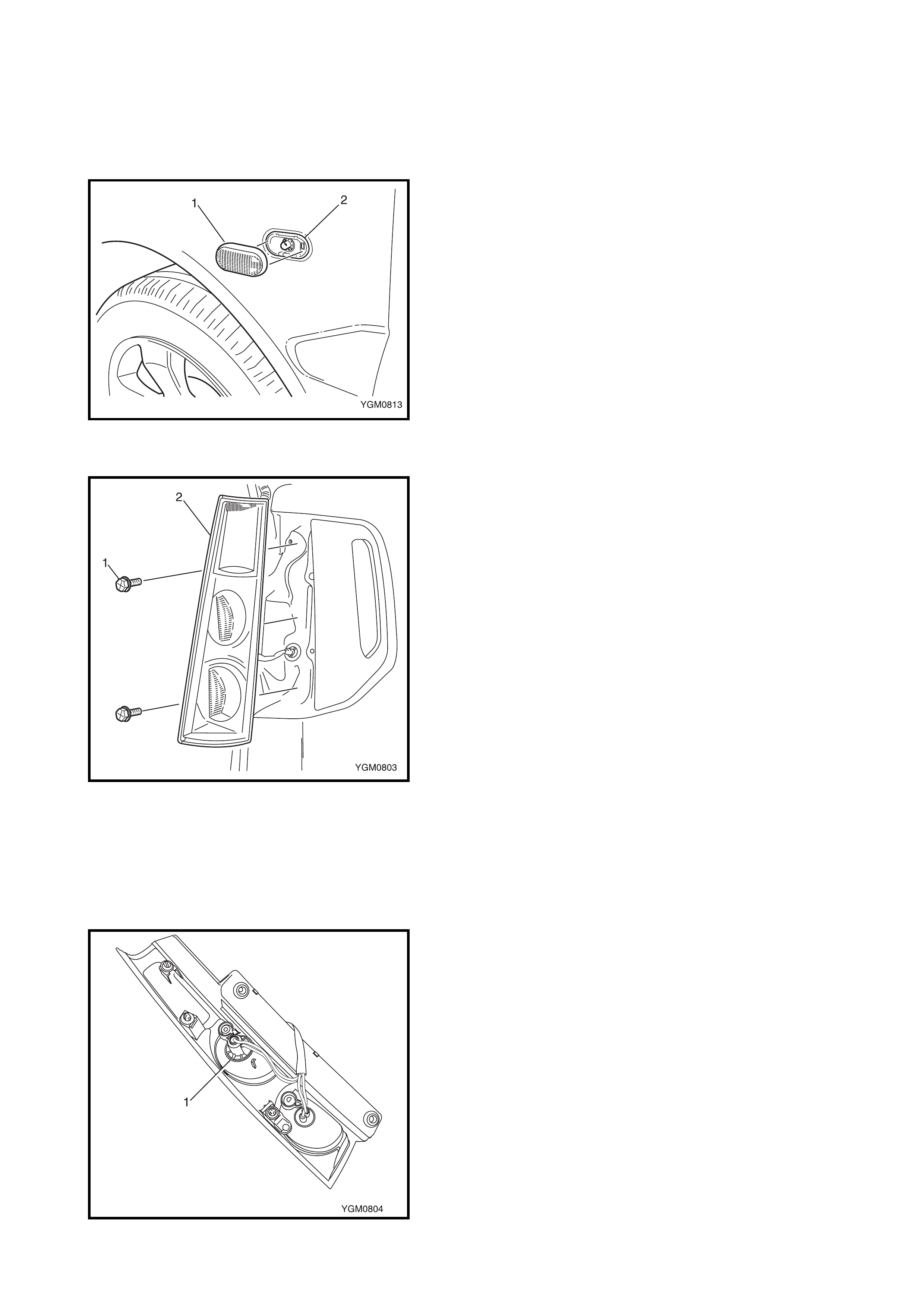
FRONT FENDER TURN SIGNAL ASSEMBLY
Removal
1. Disconnect the negative cable at the battery.
2. Partially remove the rear section of the front fender
liner, refer to 2.14 FRONT FENDER in Section 9.
3. From behin d the fe nder, s queez e the retaini ng lugs (1)
and push the turn signal light from the fender.
4. Disconne ct the wi re c on nector (2) and r em ove t he tur n
signal assembly.
Installation
Reverse removal procedure for installation.
FRONT FENDER TURN SIGNA L BULB
Replace
WARNING: To avoid being burned, don't touch t he bulb
when hot.
1. Disconnect the negative cable at the battery.
2. Locate a fine flat bla de screwdriv er in the notch on the
underside of the turn signal lamp lens, and carefully
prise the lens from the turn signal lamp housing.
3. Replace the bulb.
4. Clip the lens into position on the housing.
REAR TURN SIGNAL ASSEMBLY
Removal
1. Disconnect negative cable at battery.
2. Remove the two screws (1).
3. Carefully prise the lamp assembly (2) from the vehicle
to disengage the three retaining clips (3).
4. Remove the light sockets by twisting 90° anti-clockwise
and remove the light assembly.
Installation
Reverse removal procedure for installation.
REAR TURN SIG NAL BULB
Replace
WARNING: To avoid being burned, don't touch t he bulb
when hot.
1. Disconnect negative cable at battery.
2. Remove the rear turn signal light assembly as previ-
ously described.
3. Remove the position light socket (1) by twisting 90°
anti-clockwise.
4. Replace the bulb.
5. Reassemble removed parts.
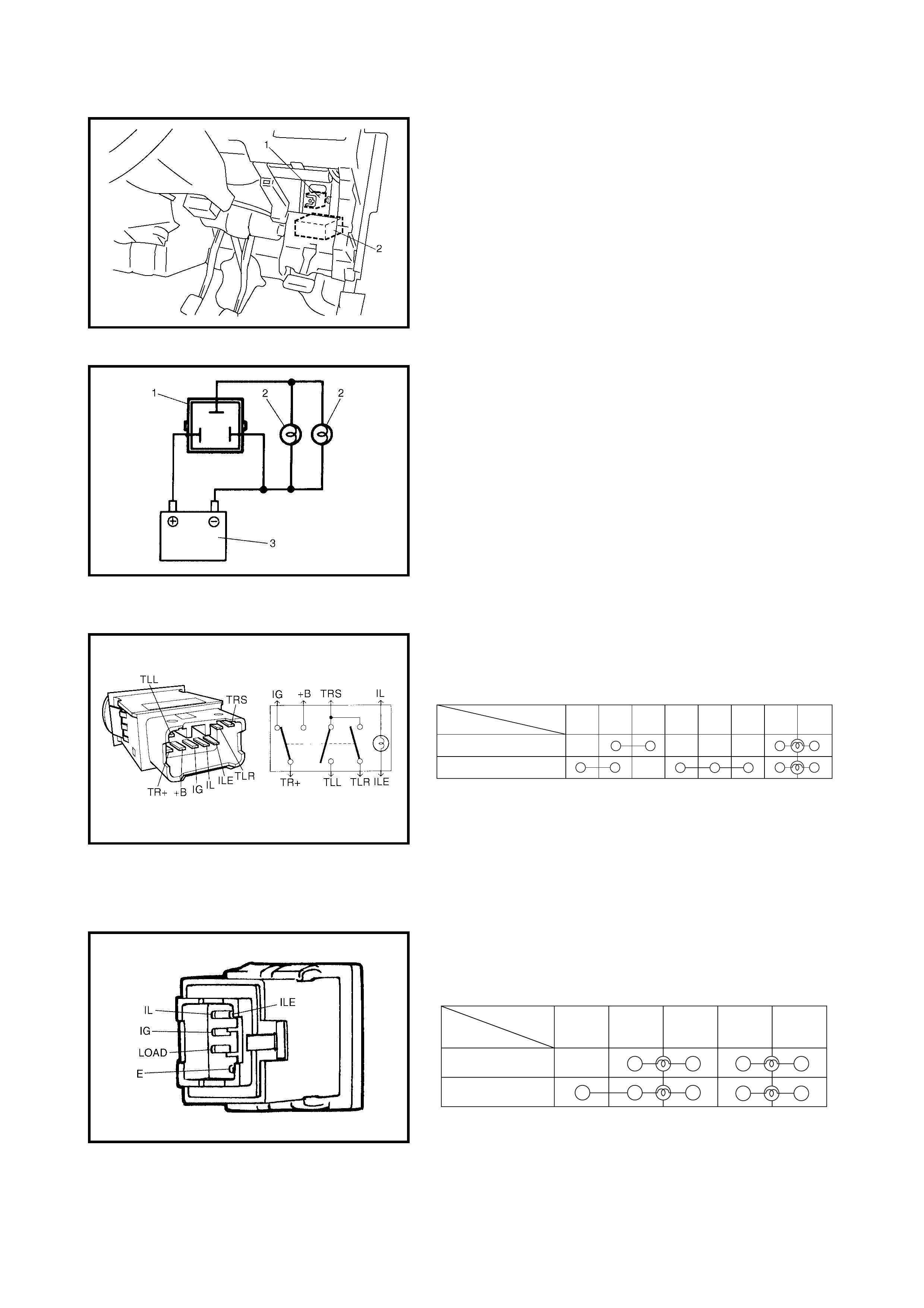
TURN SIGNAL AND HAZARD RELAY
The turn signal and hazard relay (1) is located near the
circuit fuse box (2 ).
Inspection
Connect the turn signal and hazard relay (1), battery (3)
and two test bulbs (12 V, 27 W) (2) as shown.
Unless a continued flashing off approx. 60 – 120 cycles
per minute on and off is visible, replace the relay.
HAZARD SWITCH
Inspection
Check for continuity between the terminals at each switch
position as shown below. If the check result is not as speci-
fied, replace the switch.
2.4 FRONT FOG LIGHTS
FRONT FOG LIGHT SWITCH
Inspection
Check for continuity between the terminals at each switch
position as shown below. If the check result is not as speci-
fied, replace the switch.
Hazard SW Terminal
OFF
ON
+B TR+ IG TRS TLL TLR IL ILE
Switch
Position
Terminal
ON
IG LOAD E IL ILE
OFF
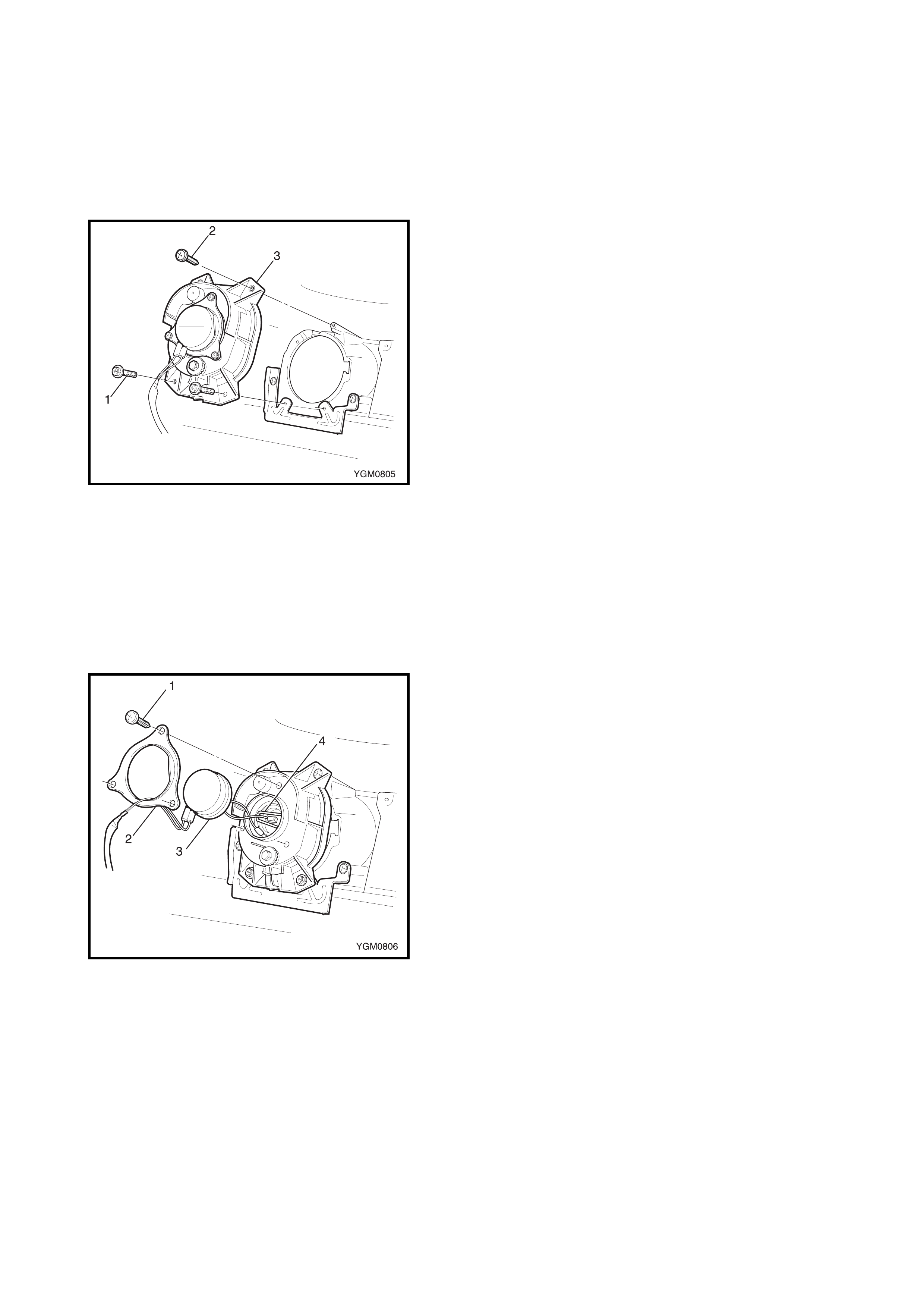
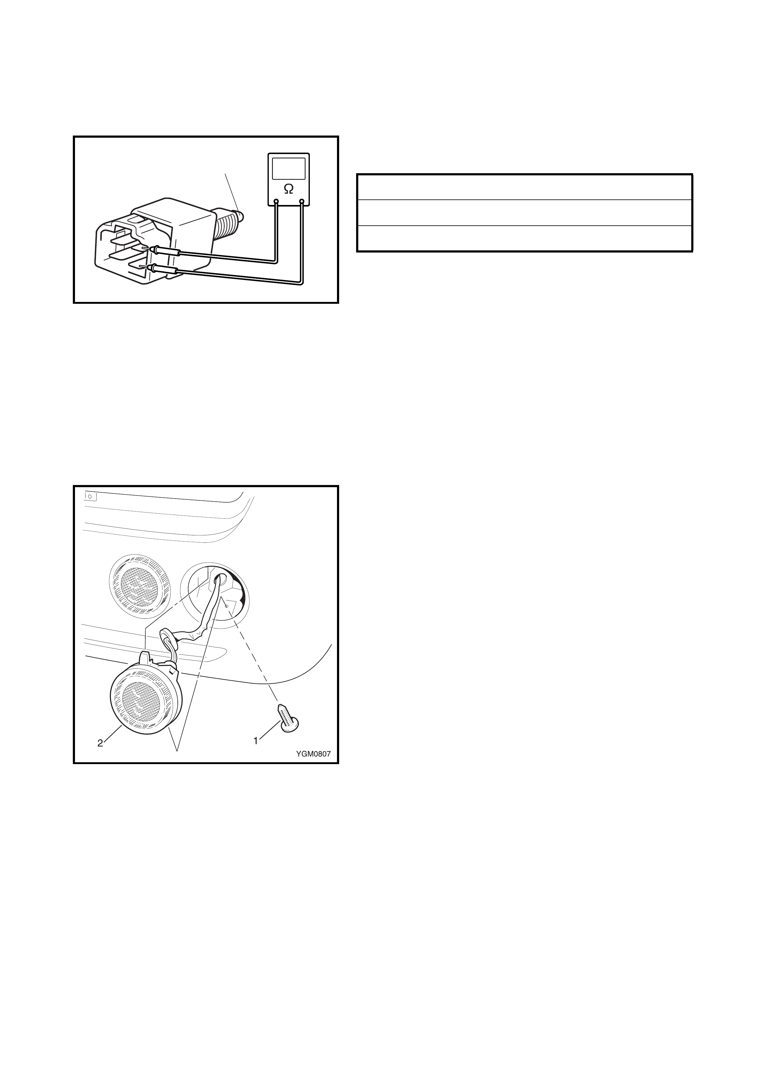
FRONT FOG LIGHT
NOTE: This procedure describes the removal of the fog
light as sembl y from i ts mountin g brack et on the ve hicle. To
remove the fog light and mounting bracket refer to
2.12 FRONT BUMPER in Section 9.
Removal
1. Disconnect the negative cable at battery.
2. Partially remove the front fender liner, refer
2.14 FRONT FENDER in Section 9.
3. Disconnect the front fog light wiring connector.
4. Remove the three screws (1) attaching the front fog
light and remove the light.
Installation
Reverse removal procedure for installation.
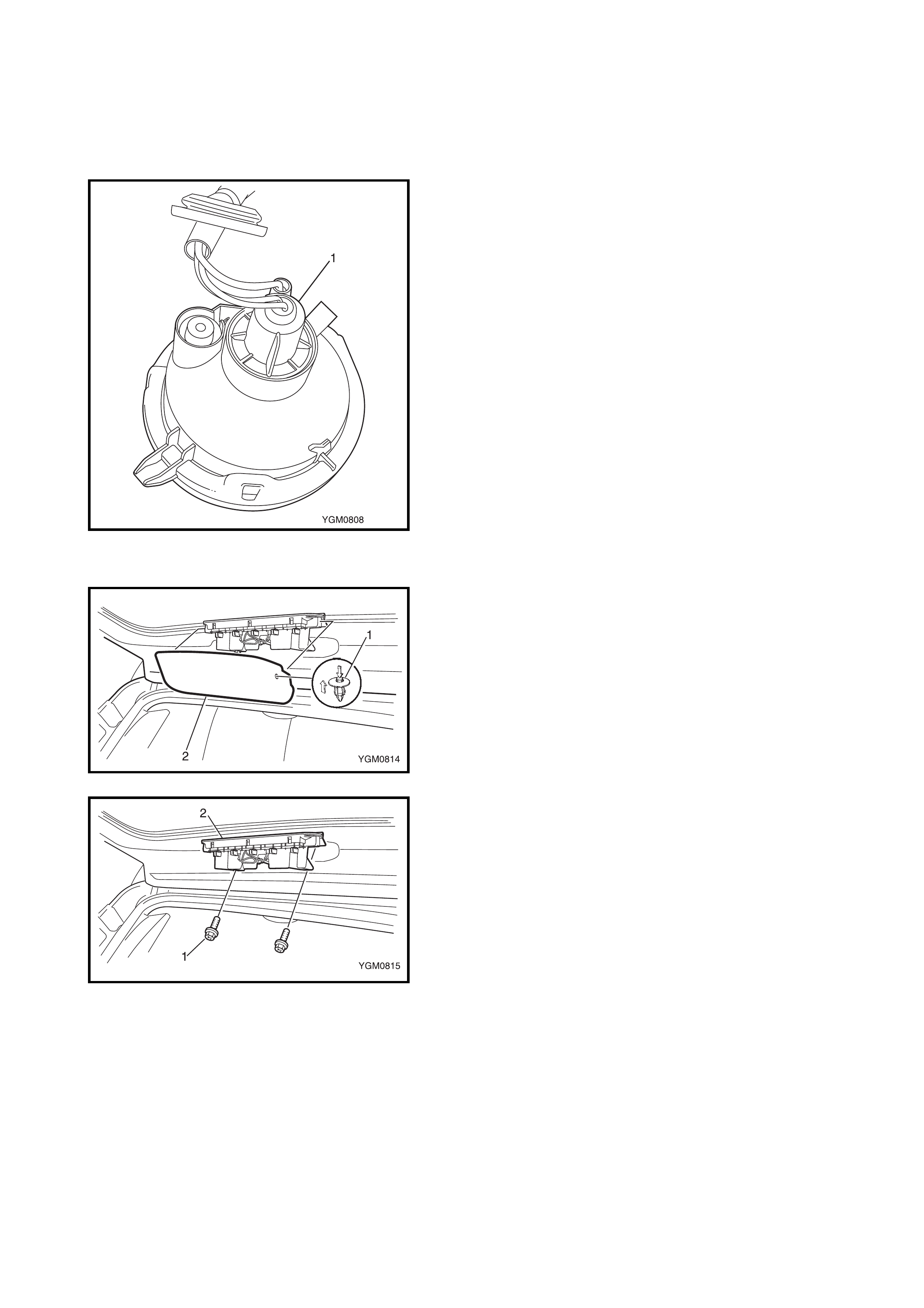
FRONT FOG LIGHT BULB
Replacement
WARNING:
• To avoid being burned, don't touch the bulb when
hot.
• Do not touch fog light bulb glass surface.
1. Disconnect the negative cable at battery.
2. Partially remove the front fender liner, refer
2.14 FRONT FENDER in Section 9.
3. Remove the three screws (1) attaching the socket
cover retainer (2).
4. Remove the retainer and socket cover (3).
5. Disconnect the front fog light bulb wiring connectors
(4).
6. Release the bulb retainer and replace the bulb.
7. Reassemb le the remov ed parts.
FRONT FOG LIGHT AIMING ADJUSTMENT WITH
SCREEN
NOTE:
• Unless otherwise obliga ted by local regulat ions, adjust
the front fog light aiming according to following
procedure.
• After replacing a front fog light, always check and
adjust aiming as required.
1. Make sure the following items:
• Place the ve hicl e on a flat surfac e in front of blank wall
(screen) (1) 10 m (a) ahead of the front fog lights.
• Adjust the tyr e air pre ssur e the sp ec ified value, refe r to
the vehicle tyre placard or owner’s manual.
• Bounce vehicle up and down by hand to stabilise sus-
pension.
• Have one perso n wei ghing appr ox. 75 k g s eate d in the
driver’s seat.
2. Turn the front fog lights ON.
3. Check to see if the cut line of each beam hot spot (1)
(high intensity zone) aligns on the screen with each
vertical front fog light centreline (A-A, B-B) and the
specifi ed distanc e (H) below the front fog ligh t horizon-
tal centreli ne (X).
4. If required, align the front fog light to specification as
follows:
• Remove the front po rtion of the front fe nder li ner, refer
to 2.14 FRONT FENDER in Section 9.
• From the rear of the front fog light (2), turn the aiming
gear (3) with a screwdriver (4) for upward adjustment
and/or (5) for downward adjustment.
FRONT FOG LIGHT HOT SPOT
SPECIFICATION: H Approx. 350 mm
2.5 BRAKE AND TAIL LIGHT
BRAKE LIGHT SWITCH
Inspection
Check brake light switch for continuity as shown.
If found detective, replace the switch.
Adjust
Refer to 2.7 BRAKE LIGHT SWITCH ADJUSTMENT in
Section 5.
TAIL LIGHT SWITCH
Refer to Headlight Switch in 2.2 HEADLIGHT AND
POSITION LIGHT in this
Section.
BRAKE AND TAIL LIGHT ASSEMBLY
Remove
1. Disconnect negative cable at battery.
2. Partially remove the rear fender liner, refer
2.13 REAR BUMPER in Section 9.
3. Disconnect the brake and tail light connector from
behind the rear bumper.
4. Remove the screw ( 1) atta ch ing the brak e an d tail l ight
(2) to the rear bumper.
5. Remove the lower part of the brake and tail light and
disengage the retaining lug.
6. Remove the brake and tail light, pulling the harness
through the bumper.
Installation
Reverse removal procedure for installation.
BRAKE LIGHT SWITCH
SWITCH DEPRESSED (1) (ON) Continuity
SWITCH RELEASED (1) (OFF) No continuity
1
BRAKE AND TAIL LIGHT BULB
Replacement
WARNING: To avoid being burned, don't touch t he bulb
when hot.
1. Disconnect negative cable at battery.
2. Remove the brake and tail light assembly as previously
described.
3. Remove the brake and tail light socket (1) by twisting
90° anti-clockwise.
4. Replace the bulb.
5. Reassemb le the remov ed parts.
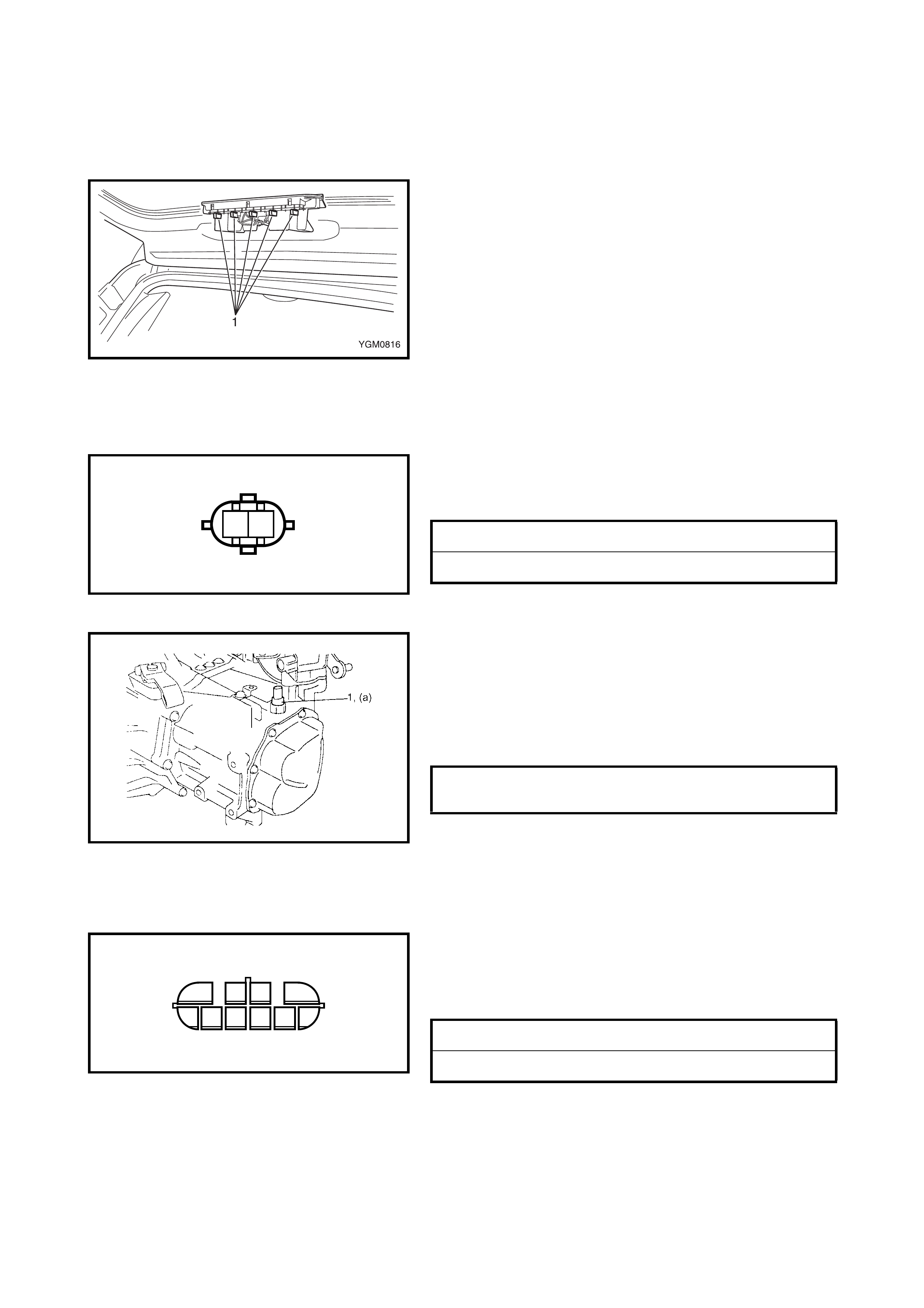
HIGH MOUNT BRAKE LIGHT ASSEMBLY
Remove
1. Disconnect negative cable at battery.
2. Remove the retainer (1) from each side of the high
mount brake light cover (2) and remove the cover.
3. Remove the two screws (1) attaching the high mount
brakelight (2) to the tailgate.
4. Disconnect the wire connector and remove the light.
Installation
Reverse removal procedure for installation.
HIGH MOUNT BRAKE LIGHT BULB
Replacement
WARNING: To avoid being burned, don't touch t he bulb
when hot.
1. Disconnect negative cable at battery.
2. Remove the high mount brake light cover as previously
described.
3. As required, remove one or more high mount brake
light sockets (1) by twisting 90°.
4. Replace the bulb.
5. Reassemb le the remov ed parts.
2.6 BACKUP LIGHT
BACKUP LIGHT SWITCH (M/T)
Inspection
Check brak e light s witch for co ntinui ty betwee n termin als 1
and 2 as shown.
If found detective, replace the switch.
Removal
1. Disconnect the wire connector.
2. Remove the backup light switch (1) from the tran-
saxle.
Installation
1.
Install the backup light switch (1) and tighten to the
specified torque
.
2. Connect the wire connector and confirm the function of
the back up light switch in reverse position.
TRANSMISION RANGE SENSOR (SHIFT SWITCH)
(A/T)
Inspection
Check tr ansm ission r ange s enso r (shift swi tch) for conti nu-
ity between terminals 7 and 8 as shown.
If not as specified, check for correct adjustment and if
required replace the sensor.
Removal / Adjustment
Refer to 3.4
TRANSMISION RANGE SENSOR
(SHIFT SWITCH) in Section 7B.
BACKUP LIGHT ASSEMBLY
Remove / Installation
Refer to 2.3 TURN SIGNAL AND HAZARD WRANING
LIGHTS in this Section.
REVERSE GEAR ENGAGED (ON) Continuity
EXCEPT REVERSE GEAR (OFF) No continuity
12
BACKUP LAMP SWITCH
TORQUE SPECIFICAT ION (a): 19.0 Nm
REVERSE GEAR ENGAGED (ON) Continuity
EXCEPT REVERSE GEAR (OFF) No continuity
12
56
3
97 8
4
10
BACKUP LIGHT BULB
Replacement
WARNING: To avoid being burned, don't touch t he bulb
when hot.
1. Disconnect negative cable at battery.
2. Remove the rear turn signal light assembly, refer
2.3 TURN SIGNAL AND HAZARD WARNING LIGHTS
in this Sectio n.
3. Remove the backup light socket (1) by twisting 90°
anti-clockwise.
4. Replace the bulb.
5. Reassemble removed parts.
2.7 LICENCE PLATE LIGHT
LICENCE PLATE LIGHT SWITCH
Removal / Inspection
Refer to Headlight Switch in 2.2 HEADLIGHT AND
POSITION LIGHT in this
Section.
LICENCE PLATE LIGHT ASSEMBLY
Remove
1. Disconnect negative cable at battery.
2. Remove the back door trim and back door licence
garnish, refer to 2.3 BACK DOOR ASSEMBLY in
Section 9.
3. Disconnect the licence plate light connector from within
the back door.
4. Depress the retaining lug on the back of the light and
remove.
Installation
Reverse removal procedure for installation.
LICENCE PLATE LIGHT BULB
Replacement
WARNING: To avoid being burned, don't touch t he bulb
when hot.
1. Disconnect negative cable at battery.
2. If requir ed, remove th e licence pl ate light ass embly as
previou sly desc ribed .
3. Remove the licence plate light cover (1) by twisting
anti-clockwise.
4. Replace the bulb.
5. Reassemb le the remov ed parts.
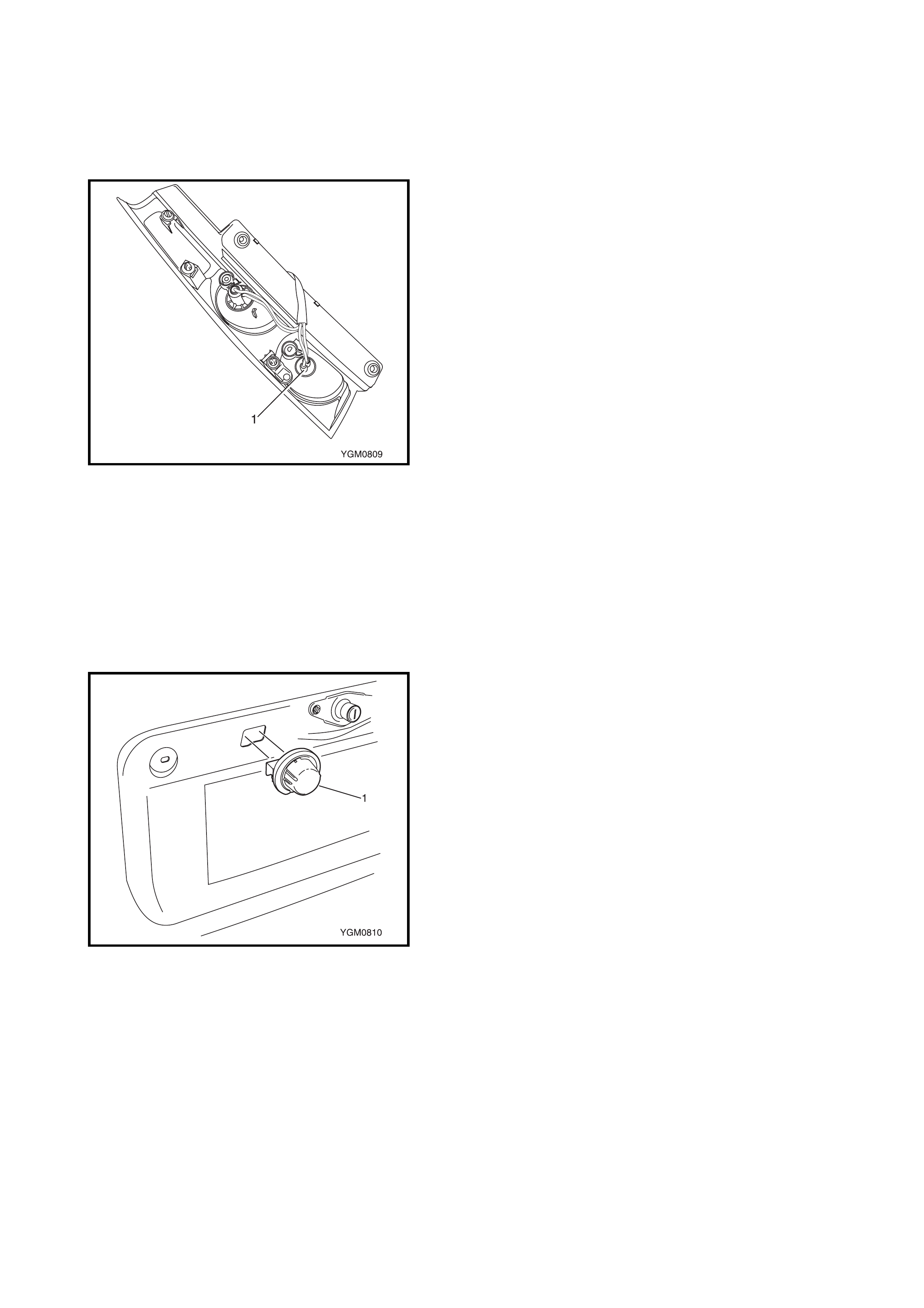
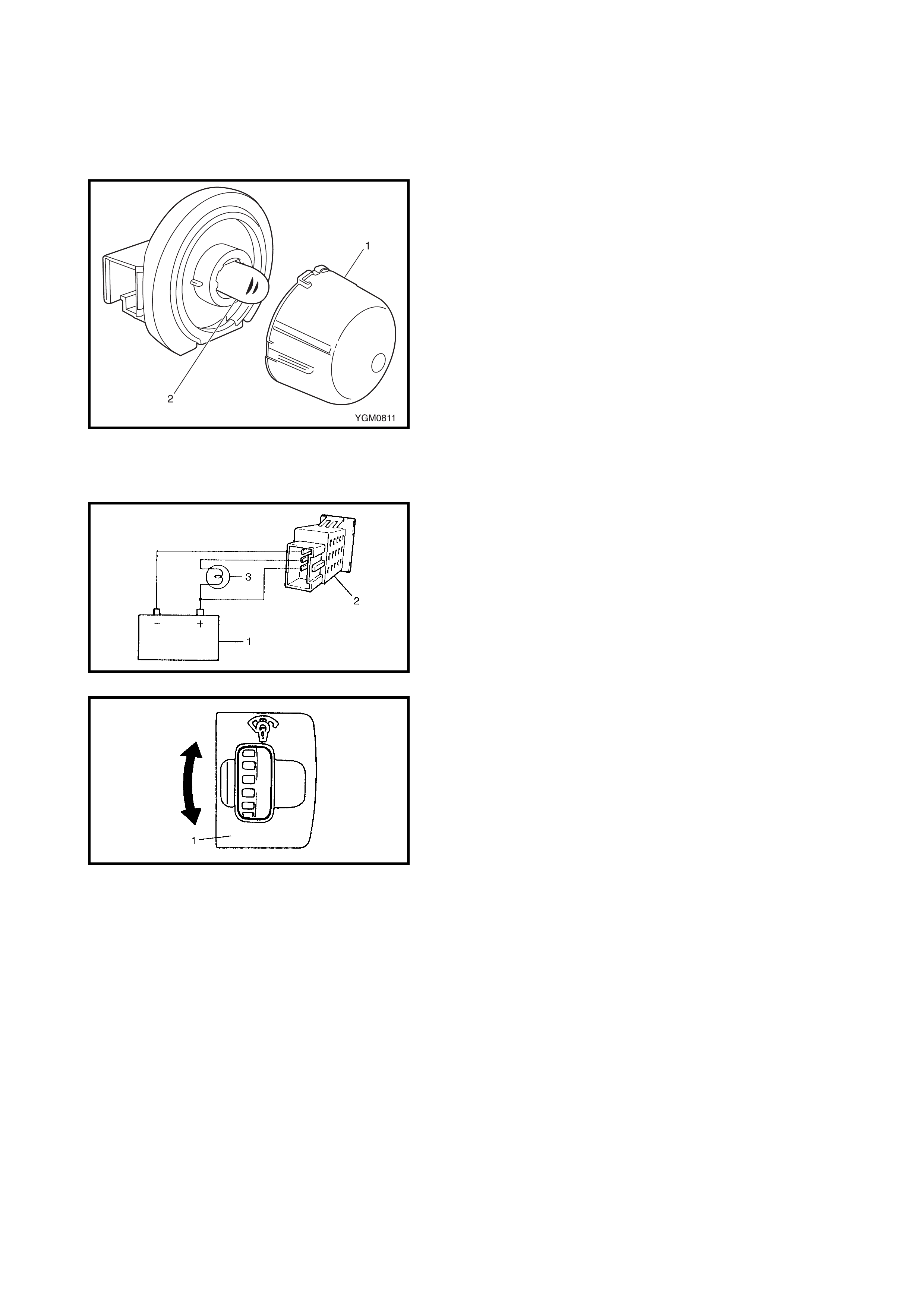
2.8 ILLUMINATION CONTROLLER
INSPECTION
1. Connect a battery (1) and test light (3) to the illumina-
tion controlle r (2) as shown.
2. Turn the illumination controller (1) up to brighten the
test lamp and down to darken it.
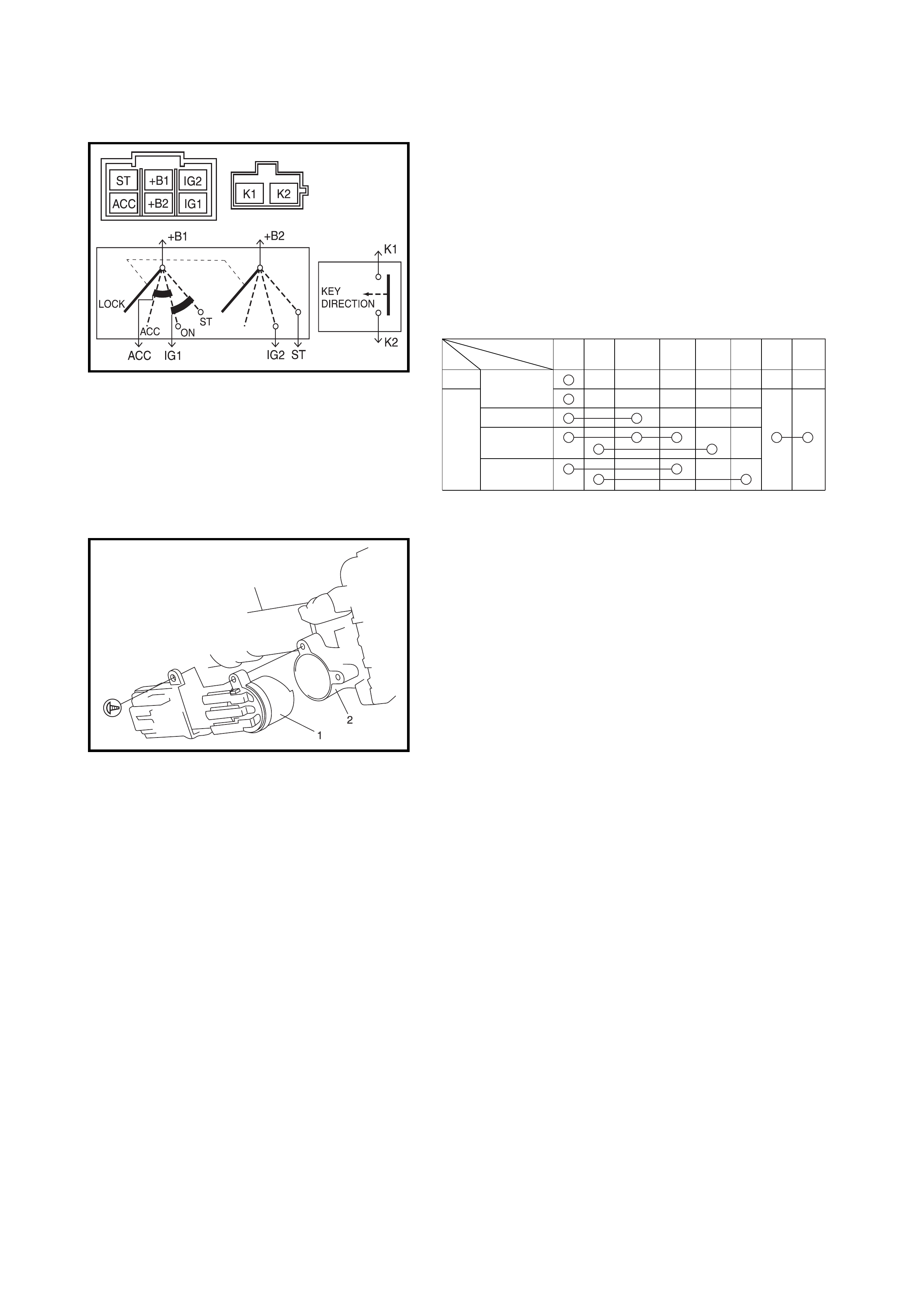
2.9 IGNITION SWITCH
ON-VEHICLE INSPECTION
1. Disconnect negative cable at battery.
2. Remove the steering column hole cover and the
steering column upper and lower covers, refer
3.6 STEERING COL UMN AS SE MBLY in Section 3C.
3. Disconnect the main harness connectors from the
ignition swi tch.
4. Check for continuity between the terminals at each
switch position as shown below. If the check result is
not as specifi ed, re pla ce the switc h.
REMOVAL
1. Disconnect negative cable at battery.
2. Remove the steering column hole cover and the
steering column upper and lower covers, refer
3.6 STEERING COL UMN AS SE MBLY in Section 3C.
3. Disconnect the main harness connectors from the
igniti on switch (1).
4. Remove ignition switch (1) from key cylinder (2).
INSTALLATION
Reverse r emoval procedure for installation.
PositionKey
OUT LOCK
ACC
ON
START
IN
+B1 +B2 +ACC IG1 IG2 ST K1 K2
Terminal
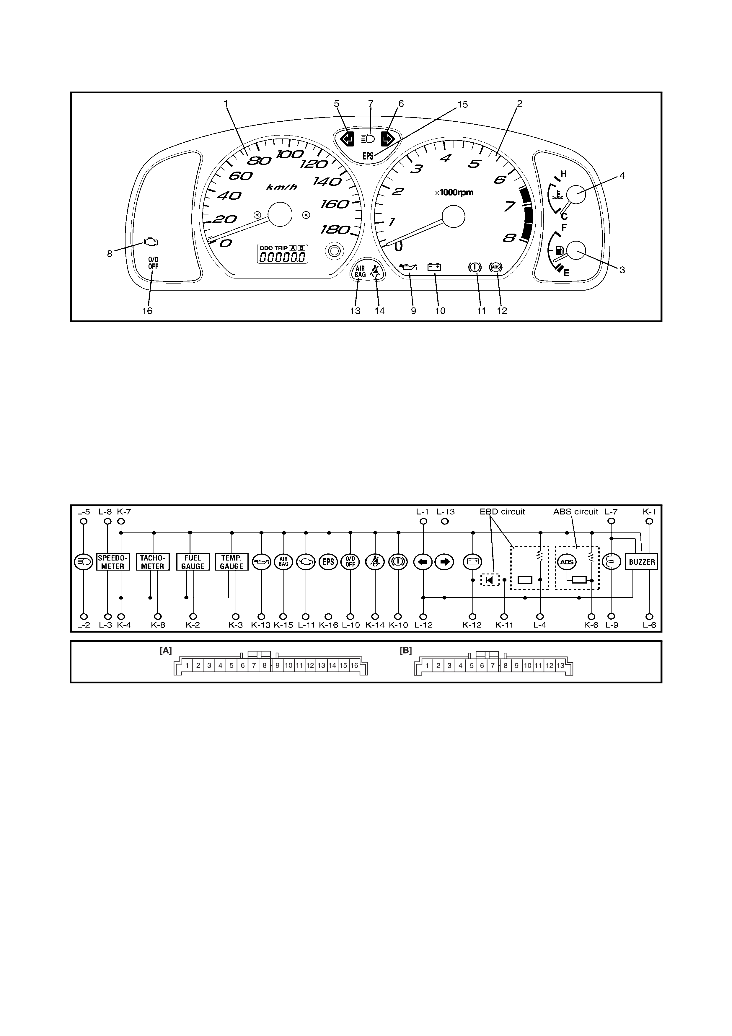
2.10 COMBINAT ION ME TER
Legend
Legend
1. Speedometer 10. Battery charging light
2. Tachometer 11. Brake system warning light (park brake
indicator, brake fluid warning, EBD system warning)
3. Fuel level gauge
4. Water temperature gauge 12. Anti-lock brake system (ABS) warning light
5. Turn signal indicator (LH) 13. AIR BAG warning light
6. Turn signal indicator (RH) 14. Seat belt light
7. High beam indicator 15. Electronic power steering (EPS) warning light
8. Malfunction indicator light (MIL) 16. O/D OFF indicator (A/T only)
9. Engine oil pressure warning light
[A]: Connector K [B]: Connector L
1. To EPS YEL 1. To combination switch (tur n R) BLU/YEL
2. To SDM YEL/BLK 2. To ground BLK
3. To seat belt switch BRN/YEL 3. To ECM PPL/WHT
4. To oil pressure switch YEL/BLK 4. To TCM RED/BLK
5. To generator WHT/BLU 5. To ground RED/BLU
6. To parking brake switch RED/BLK 6. To main fuse WHT/RED
7. To brake fluid level switch RED/BLK 7. To combination switch (dimmer) RED/YEL
8. Blank – 8. To door switch BLK/YEL
9. To ECM BRN 9. To main fuse WHT/BLU
10. To ignition switch BLU 10. To ABS control module PNK/BLU
11. To ABS control module RED/BLU 11. To VSS PPL
12. Blank – 12. To combination switch (dimmer) RED
13. To ground BLK/ORN 13. To combination switch (turn L) GRN/RED
14. To ECT sensor YEL/BLU
15. To fuel level gauge YEL/RED
16. To ignition switch BLU/YEL
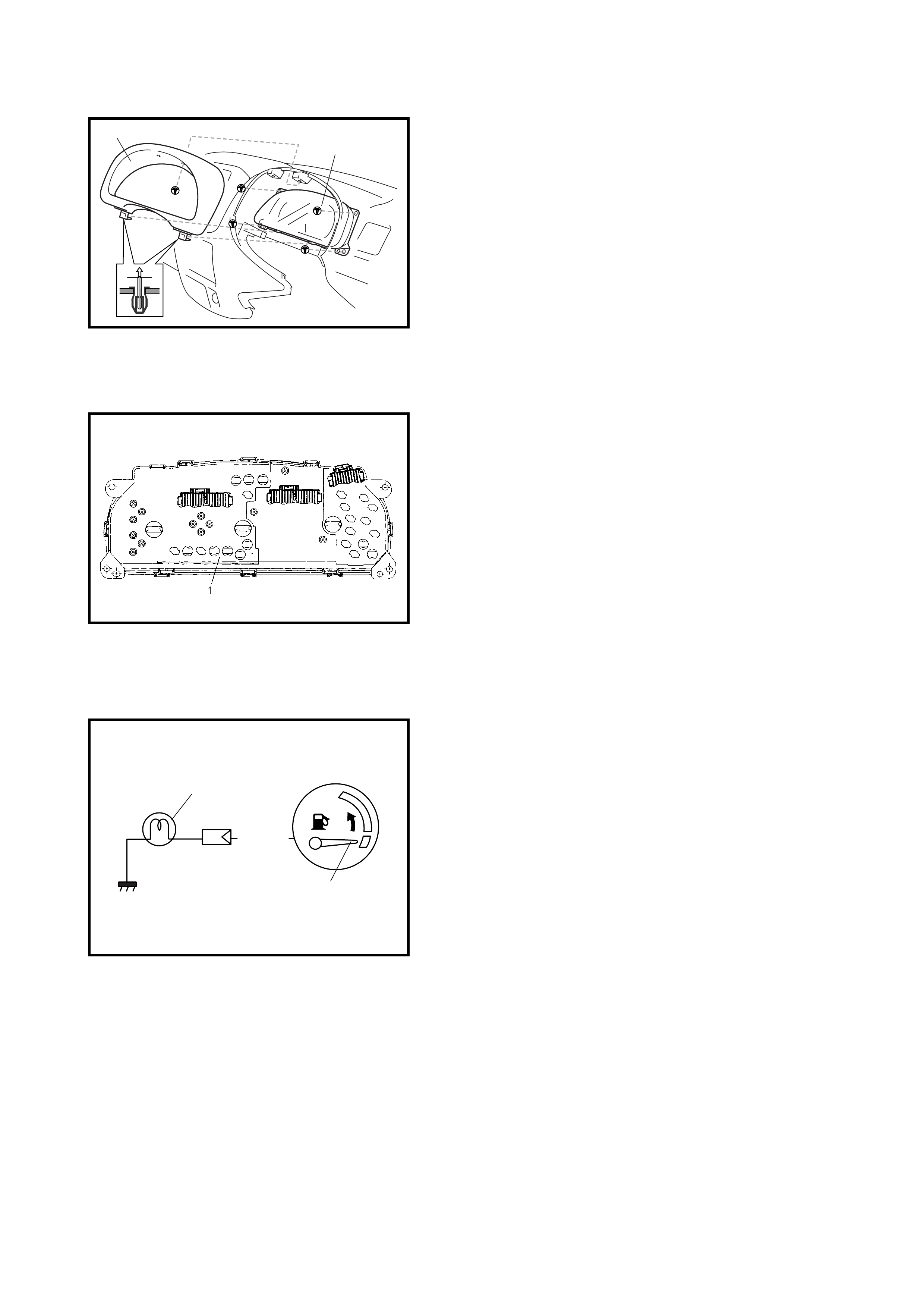
REMOVAL
1. Disconnect negative cable at battery.
2. Loosen the steering column mounting nuts, refer to
3.6 STEERING COL UMN AS SE MBLY in Section 3C.
3. Remove the combination meter cluster panel (1).
4. Disconnect all connectors from the combination meter
and remove the combination meter (2).
INSTALLATION
Reverse removal procedure for installation.
INSPECTION
Check the printed plate (1) visually for scratches, cracks
and discolouration.
If any fault is found, replace the printed plate (1).
2.11 FUE L GAUGE AND FUE L LEVEL SENSOR (GAUGE UNIT)
FUEL GAUGE
Operation Check
1. Remove the combination meter as previously
described.
2. Remove the YEL/RED wire terminal from the combina-
tion meter connector and reconnect the combination
connectors to the combination meter.
3. Tu rn the ig nit ion switc h ON, and check t hat the poi nter
(2) of fuel gauge indicates E.
4. Turn ignition switch OFF.
5. Short the YEL/RED wire terminal to body ground
through a 3.4 W bulb (1) as shown.
6. Turn the ignition switch ON, and check that the bulb
illuminates and the gauge pointer (2) moves from E
to F.
If the check result is not satisfied, replace the fuel
gauge.
FUEL LEVEL SENSOR (GAUGE UNIT)
Removal
Remove th e fuel p ump as sembly, refer to 2.8 FUEL P UMP
ASSEMBLY in Section 6C.
Installation
Install the fuel pump assembly, refer to
2.8 FUEL PUMP
ASSEMBLY in
Section 6C.
12
YEL/RED
F
E
2
1
INSPECTION
• Check that the resistance between terminals a and b of
fuel level s en so r c onn ect or o n the top o f t he fue l pum p
assembly (1) changes with movement of float position.
• Check the resistance between terminals a and b in
each float position below.
If the measured value is out of specification, replace.
2.12 SPEEDOMETER AND VEHICLE SPEED SENSOR (VSS)
VEHICLE SPEED SENSOR
(VSS)
Removal and Installation
Refer to 3.4 VEHICLE SPEED SENSOR (VSS) in
Section 7A.
Inspection
Refer to 2.22 DTC P0500 (DTC No.16) VEHICLE SPEED
SENSOR (VSS) MALFUNCTION in Section 6.
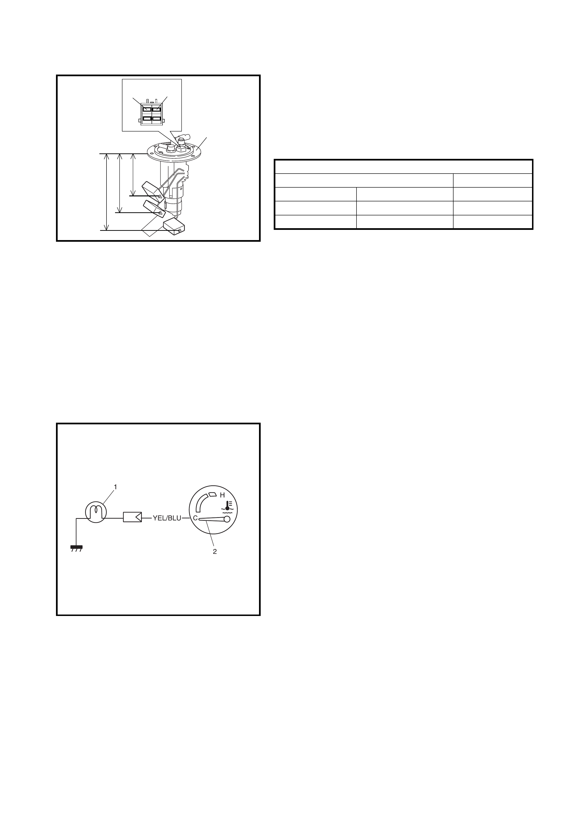
2.13 ENGINE COOLANT TEMPERATURE (E CT) GAUGE AND SENSOR
ENGINE COOLANT TEMPERATURE (ECT) GAUGE
Inspection
1. Remove the combination meter, refer to
2.10 COMBINATION METER in this Section.
2. Remove the YEL/BLU wire terminal from the combina-
tion meter connector and reconnect the combination
connectors to the combination meter.
3. Tu rn the ig nit ion switc h ON, and check t hat the poi nter
(2) of the ECT gauge indicates C as shown.
4. Turn the ignition switch OFF.
5. Short the YEL/BLU wire terminal to body ground
through a 3.4 W bulb (1) as shown.
6. Turn the ignition switch ON, and check that the bulb
illuminates and the gauge pointer (2) moves from C
to H.
If the check result is not satisfied, replace the gauge.
ECT SENSOR
Removal, Installation and Inspection
Refer to 2.3 ELECTRONIC CONT ROL SYSTE M in
Section 6E1.
Fuel Level Sensor Specification
Float Position Resistance (Ω)
Full Upper (c) 59.6 mm 2 - 4
Middle (1/2) (d) 121.6 mm 29.5 - 35.5
Full Lower (e) 202.3 mm 119 - 121
“a” “b”
1
“c”
“d”
“e”
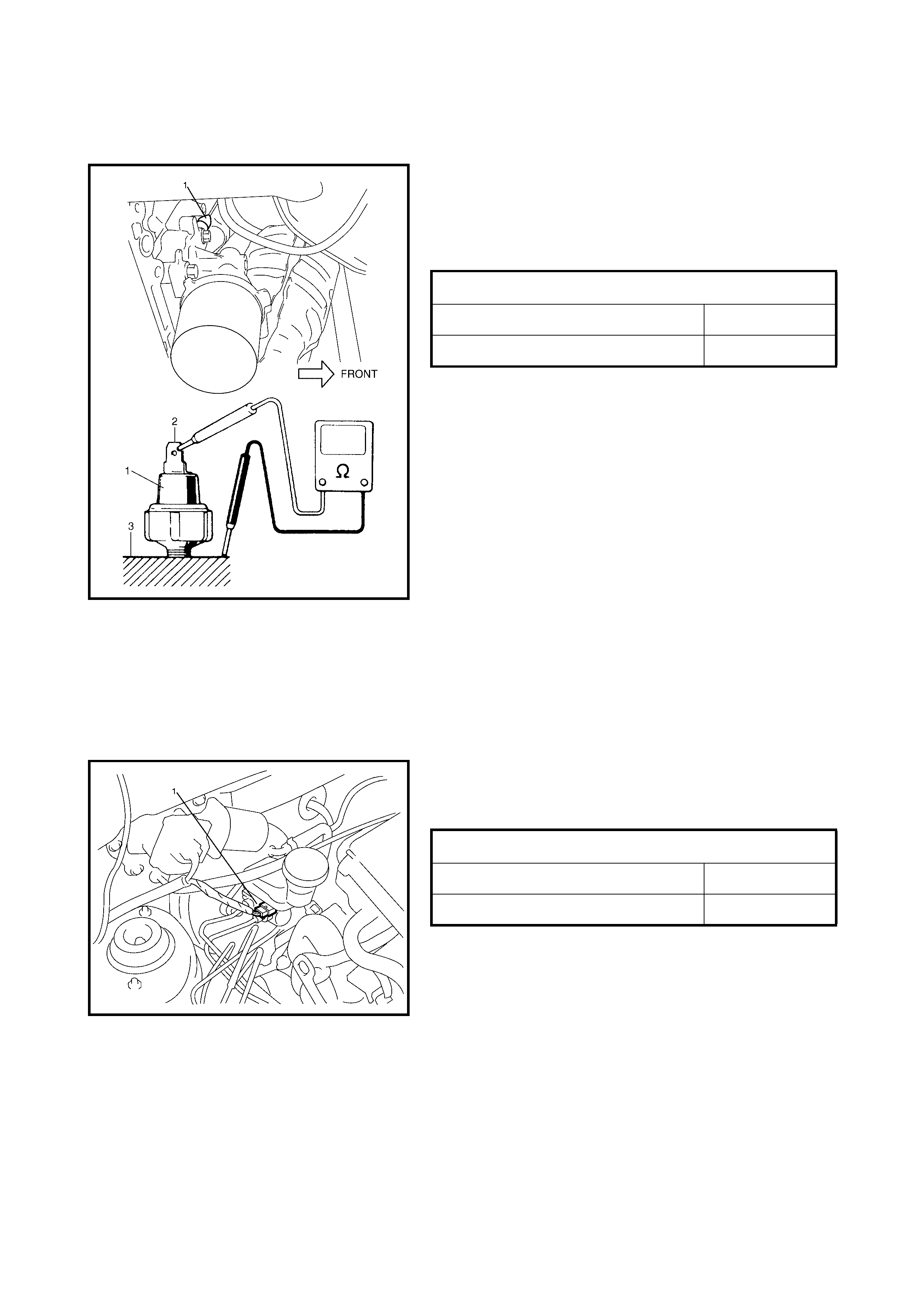
2.14 ENGINE OIL PRES SURE WARNING LIGHT
ENGINE OIL PRESSURE SWITCH
On-vehicle Inspection
1. Disconnect the engine oil pressure switch (1) lead wire.
2. Check for continuity between the engine oil pressure
switch terminal (2) and the cylinder block (3) as shown.
If not to specification, replace the engine oil pressure
switch.
Removal and Installation
Refer to 2.4 OIL PRESSURE CHECK in Section 6A1.
2.15 BRAKE SYSTEM WARNING LIGHT (PARKING BRAKE INDICATOR, BRAKE
FLUID WARNING AND EBD S YSTEM WARNING LIGHT)
BRAKE FLUID LEVEL SWITCH
Inspection
Check for continuity between the terminals of the brake
fluid level switch connector (1).
If found defective, replace the switch.
ENGINE OIL PRESSURE SWI TCH SPECIF ICATION
DURING ENGINE RUNNING: No Continuity
AT ENGINE STOP: Continuity
BRAKE FLUID LEVE L SWI TCH SPECIFICATION
OFF (FLOAT UP): No Continuity
ON (FLOAT DOWN): Continuity

PAR KING BRAKE SWITCH
Inspection
Check for conti nui ty betwe en the parking br ake switc h
terminal and body ground as shown.
If found defective, replace the switch.
2.16 REAR WINDOW DEFOGGER
DEFOGGER SWITCH
Inspection
Check for continuity between the terminals at each switch
position as shown below. If the check result is not satisfied,
replace the switch.
DEFOGGER WIRE
Inspection
NOTE:
• When cleaning the rear window glass, use a dry cloth
to wipe along the heat wire (1) direction.
• When cleaning the glass, do not use detergent or
abrasive-containing glass cleaner.
• When measuring wire voltage, use a tester with
negative probe (2) wrapped in tin foil (3) which should
be held down on the wire by finger pressure.
• Wire damage inspection:
a. Turn the ignition switch ON.
b. Turn the defogger switch ON.
c. Check the voltage at the centre (1) of each heat
wire as shown below.
If the measured voltage is 10V, the wire must be
damaged (x) between its centre and positive (+)
end (5).
If the voltag e is 0 V, the wi re must be damage d (x)
between its centre and ground (-) end (6).
PARKING BRAKE SWITCH SPECIFICATION
OFF (PARKING BRAKE RELEASED)
(1): No Continui ty
ON (PARKING BRAKE ENGAGED) (2): Continuity
SwitchPosition
Terminal
ON (PUSH IN)
IG LOAD E IL ILE
OFF
Voltage Criteria
Approx. 4 - 6 V (2) Good (No break in wire)
Approx. 9 - 11 V (3) or 0 - 2 V (4) Broken wire
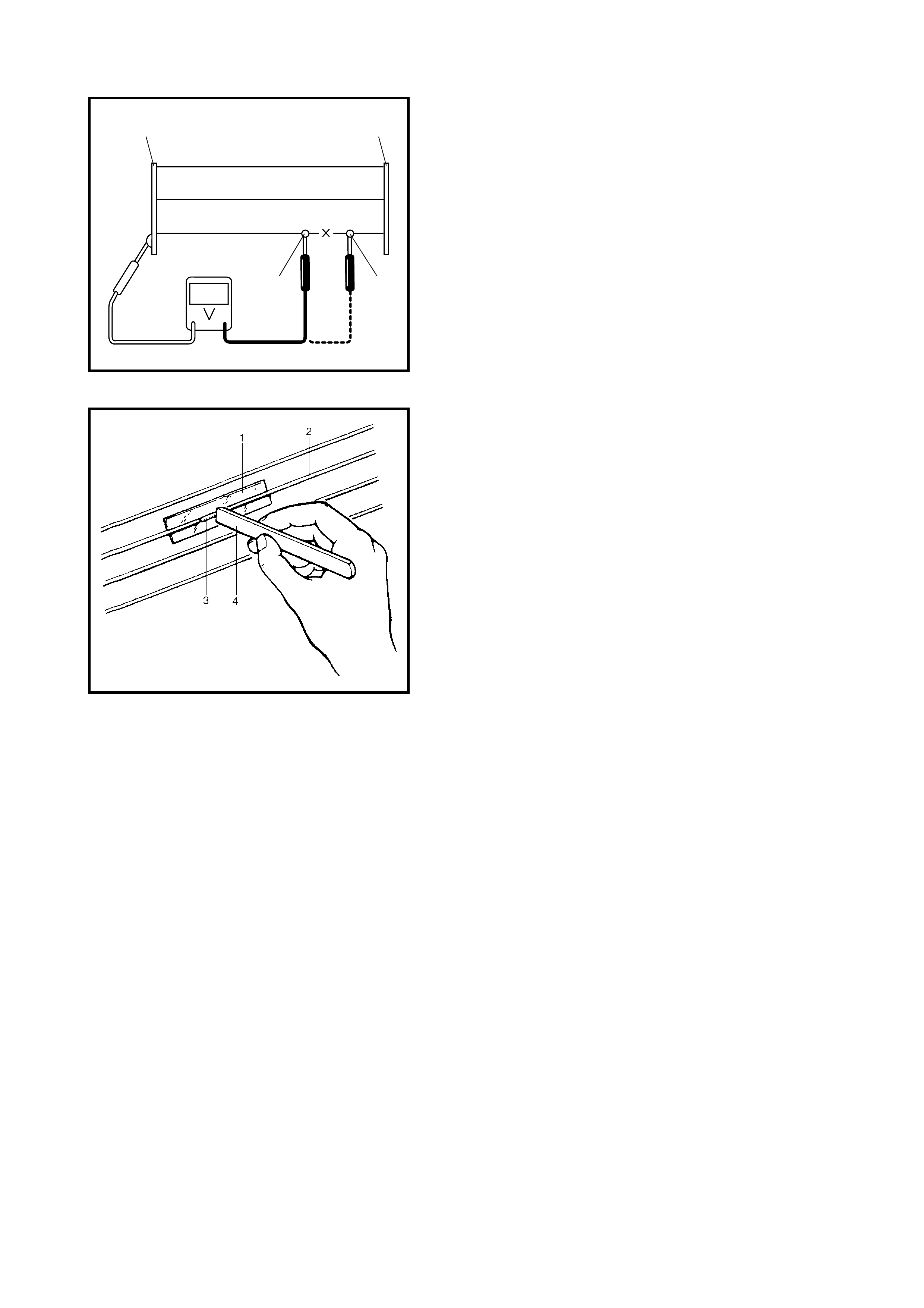
• Damage point (x) locating:
a. Turn the ignition switch ON.
b. Turn the defogger switch ON.
c. Touch the voltmeter positive (+) lead to the heat
wire positive terminal end (1).
d. Touch the voltmeter negative (-) lead with a foil strip
to the heat wire positive terminal (+) end (1), then
move it along the wire to the negative terminal (-)
end (2).
e. The place where the vo ltm ete r flu ctuates fr o m 0 - 2
V (3) to several volts (4) is where there is damage.
Repair
1. Use white gasoline for cleaning.
2. Apply masking tape (1) at both the upper and lower
sides of the heat wire (2) to be repaired.
3. Apply a commercially-available repair agent (3) with a
fine-tip brush (4).
4. 2 to 3 minutes later, remove the masking tape (1).
5. Leave the repaired heat wire as it is for at least 24
hours before operating rear defogger.
+-
3
12
4
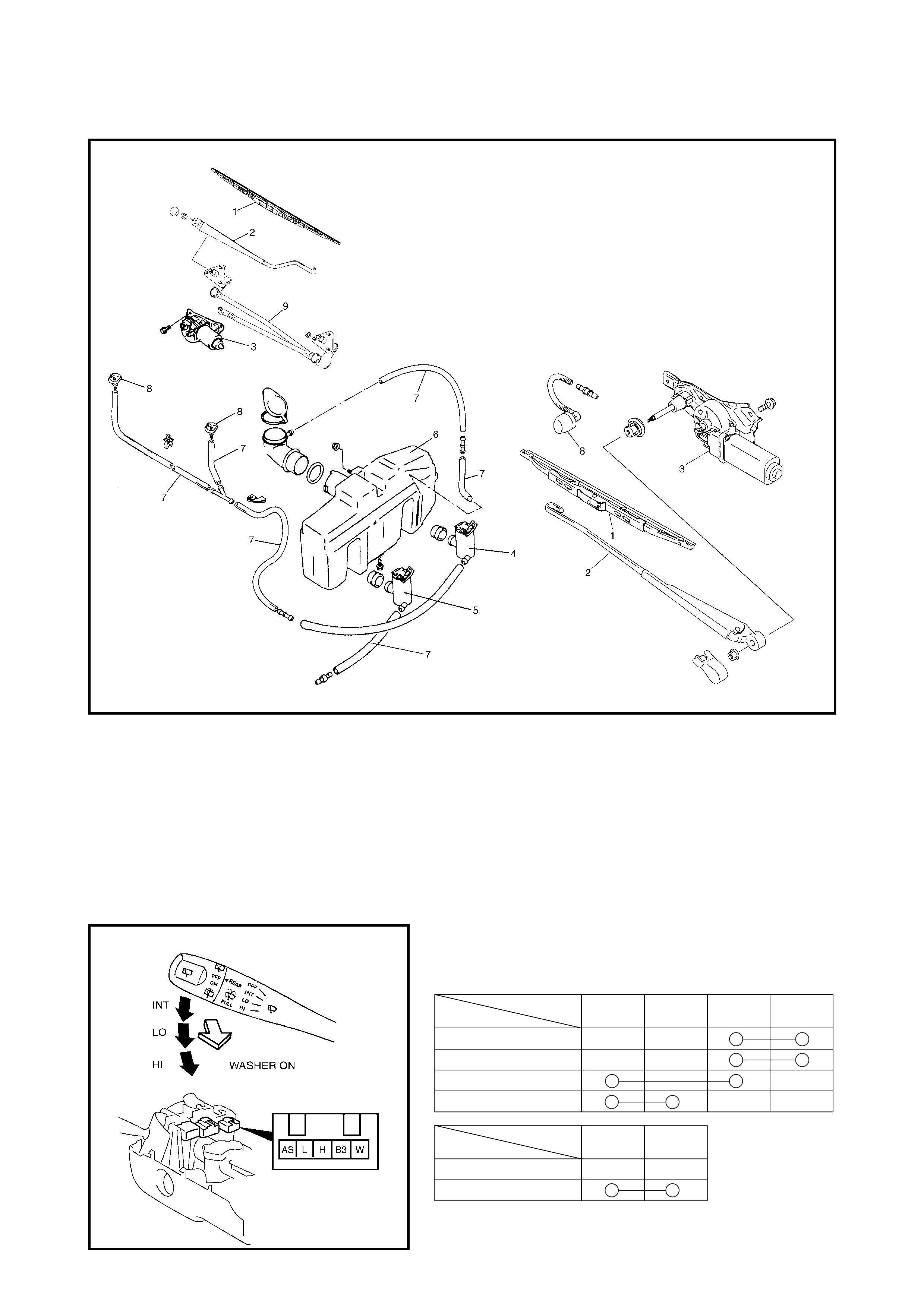
2.17 WIPERS AND WASHERS
COMPONENTS
Legend
FRONT WIPER AND W ASHER SWITCH
Removal and Installation
Refer to 3.5 CONTACT COIL AND COMBINATION
SWITCH ASSEMBLY in Section 3C.
Inspection
Check for continuity between the terminals at each switch
pos ition as shown below.
If the check result is not as specified, replace the switch.
1. Wiper blade 4. Washer pump (for front washer) 7. Washer hose
2. Wiper arm 5. Washer pump (for rear washer) 8. Washer nozzle
3. Wiper motor 6. Washer tank 9. Wiper link
Terminal
Wiper SW
OFF
INT
LO
B3 H L AS
HI
Terminal
Washer SW
OFF
ON
B3 W
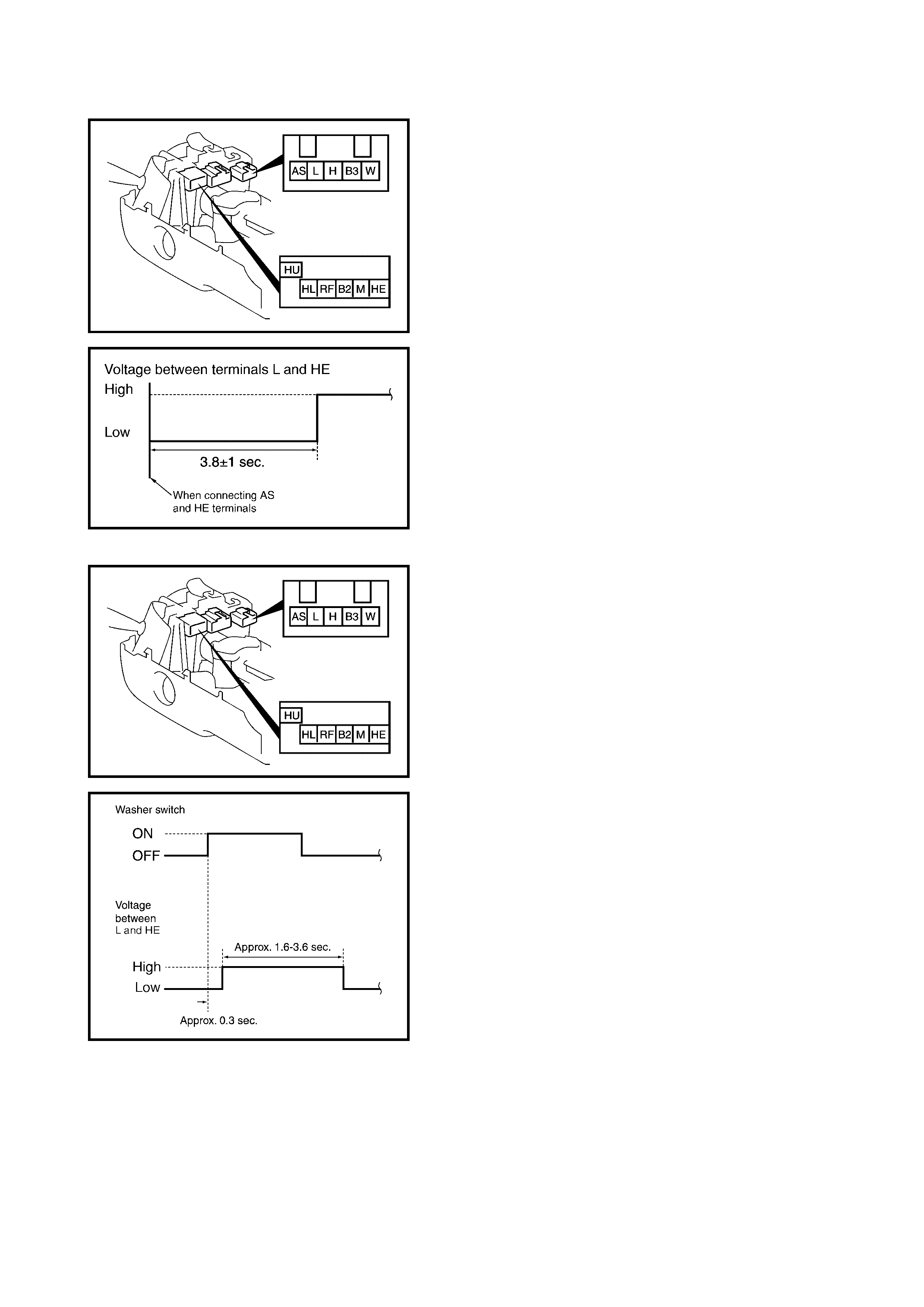
Intermittent Wiper Relay Circuit Inspection
1. Turn the front wiper switch to INT position.
2. Connect battery positive to terminal B3 and negative to
terminal HE.
3. Connect a voltmeter positive lead to terminal L and
negative lead to terminal HE.
4. Check that the voltmeter indicates battery voltage
(10 – 14 V).
5. Connect a jumper wire between terminal AS and
terminal B3 for 5 seconds or more.
6. Disconnect the jumper wire from terminal B3.
7. Connect the disconnected end of the jumper wire to
terminal HE and check that the voltage between
terminal L and terminal HE changes as shown.
If check result is not satisfied, replace.
Washer Linked Circuit Inspection
1. Make sure that the front wiper switch is OFF position.
2. Connect battery positive to terminal B3 and negative to
terminal HE.
3. Connect a voltmeter positive lead to terminal L and
negative lead to terminal HE.
4. When the front washer switch is ON (pushed to
forward), check that the voltage changes as shown in.
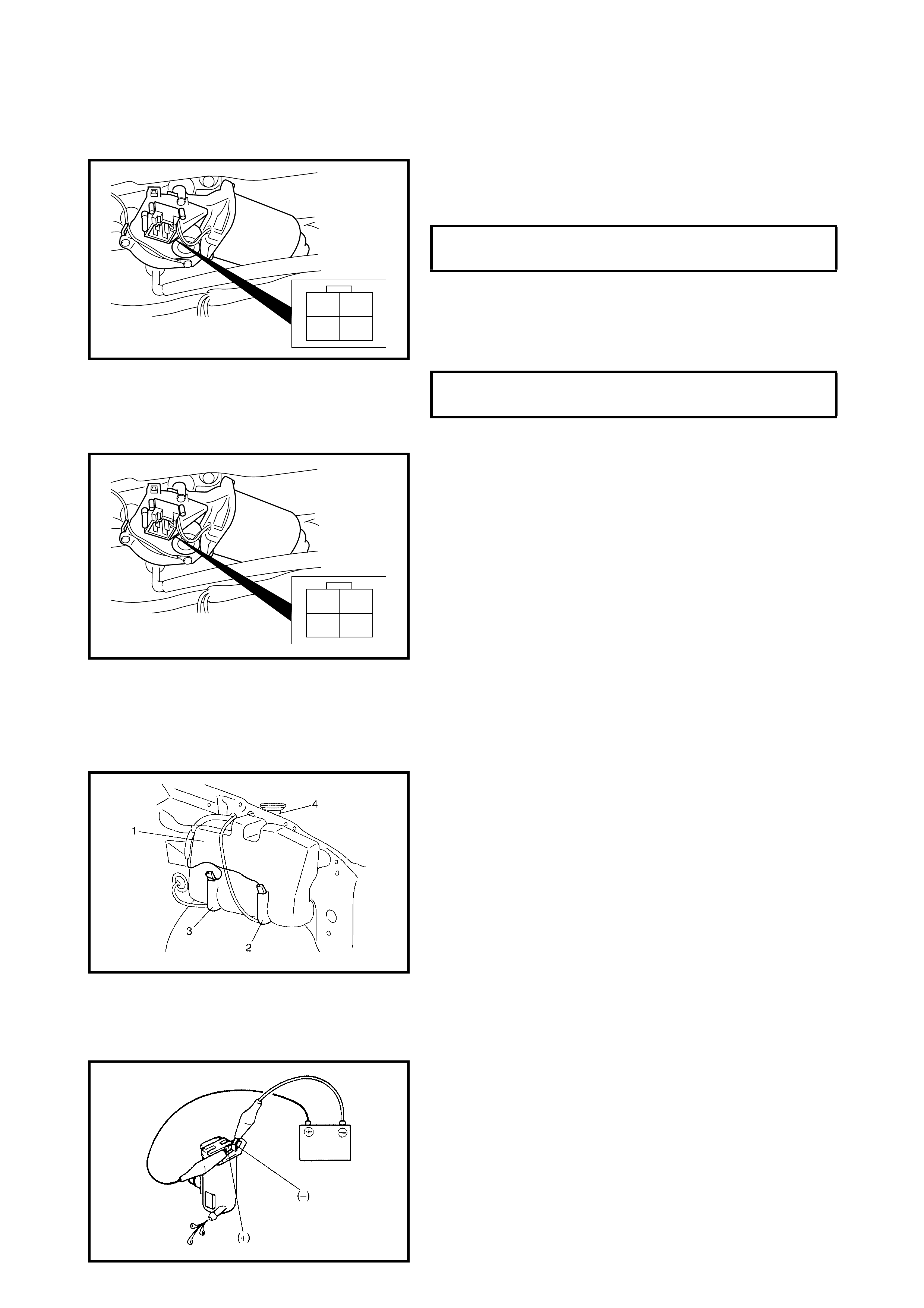
FRONT WIPER MOTOR
Inspection
Motor Operation (Low Speed)
1. Connect battery positive to terminal L and negative to
the motor bracke t (wip er ground) .
2. Check motor revolution speed.
Motor Operation (High Speed)
1. Connect battery positive to terminal H and negative to
the motor bracke t (wip er ground) .
2. Check motor revolution speed.
Automatic Stop Operation
1. Connect battery positive to terminal L and negative
terminal to the motor bracket (wiper ground) and let the
motor turn.
2. Disconne ct term inal L from the batt ery pos itive, and let
the motor stop.
3. Connect terminal L and S with a jumper wire, and
connect terminal B to battery positive. Observe that the
motor turns once again and then stops at a specified
position.
4. Repeat Steps 1 to 3 several times and check that the
motor stops at the specified position every time.
If check result is not satisfied, replace the front wiper
motor.
WASHER TANK AND WASHER PUMP
Removal
1. Disconnect the battery negative cable.
2. Remove the RH front fender liner, refer
2.14 FRONT FENDER in Section 9.
3. Remove the washer tank attaching nuts and inlet pipe
(4).
4. Disconnect the pump wire connector(s) and hoses.
5. Remove the washer tank (1).
6. Remove the front washer pump (2) and rear washer
pump (3) from the washer tank.
Installation
Reverse removal procedure for installation.
Inspection
1. Connect battery (+) and (-) to the pump (+) and (-)
terminal s re sp ec tivel y.
2. Check motor operation for both front and rear washer
pumps.
FRONT WIPER MOTOR SPECIFICA-
TION (LOW SPEED) 44 – 52 rpm
FRONT WIPER MOTOR SPECIFICA-
TION (HIGH SPEED) 64 – 78 rpm
LH
S
B
LH
S
B
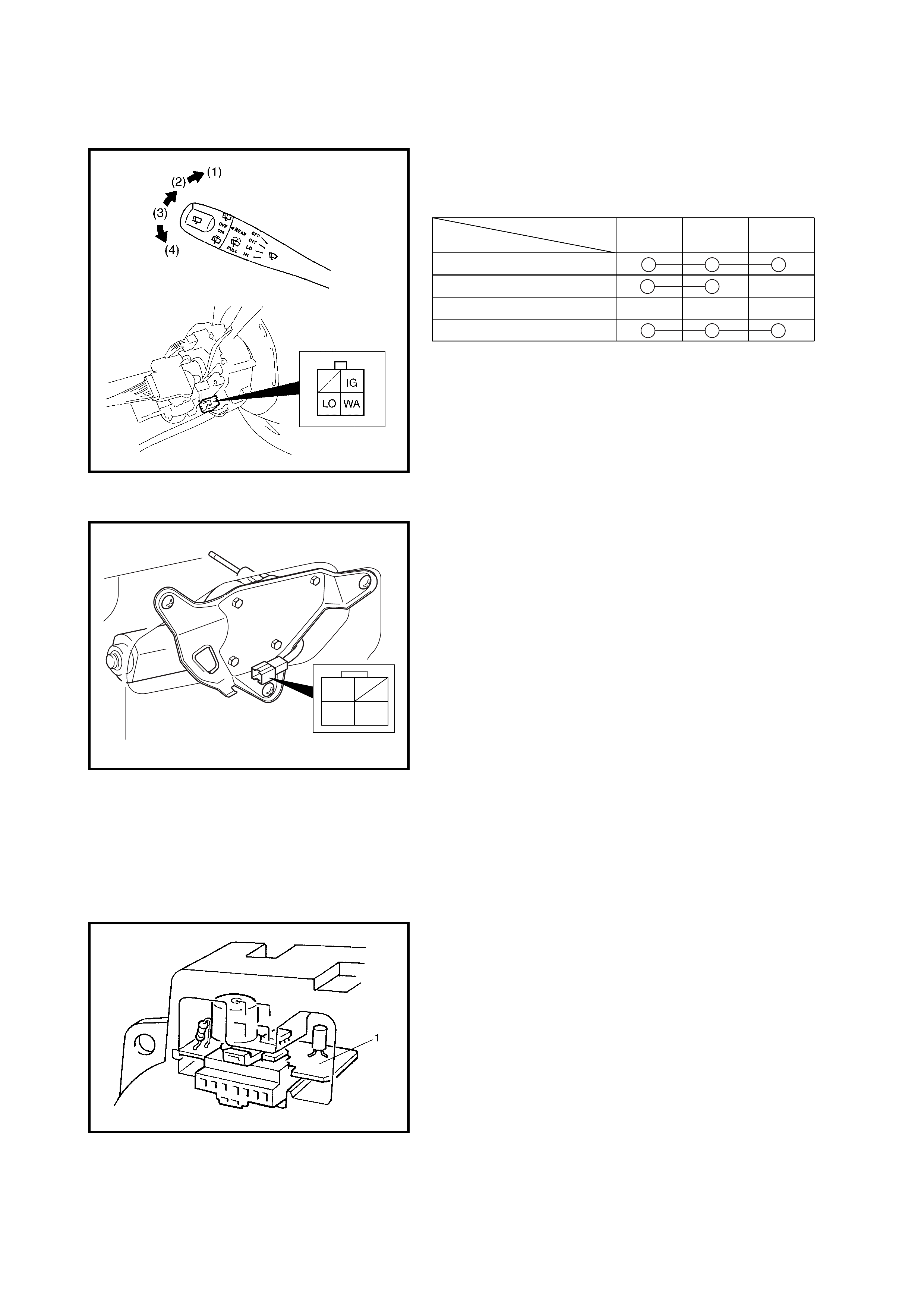
REAR WIPER AND W ASHER SWITCH
Inspection
Check for continuity between the terminals at each switch
pos ition as shown below.
If the check result is not as specified, replace the switch.
REAR WIPER MOTOR
Inspection
Wiper Motor
Use a 1 2 V battery and connect its (+) and (-) termin als to
terminal L and terminal E respectively. The motor should
rotate at 35 to 45 rpm.
Automatic Stop Operation
1. Connect battery positive to terminal L and negative to
terminal E and let the motor turn.
2. Disconnect the battery from terminal L and let the
motor stop.
3. Connect battery positive to terminal B. Observe that
the motor turns once again and then stops at a
specified position.
4. Repeat Steps 1 to 3 several times and check that the
motor stops at the specified position every time.
If check result is not satisfied, replace the rear wiper
motor.
2.18 IGNITION KEY REMINDER AND LIGHT REMINDER WARNING BUZZER
REMOVAL
1. Remove the combination meter. Refer to
2.10 COMBINATION METER in this Section.
2. Remove the buzzer unit (1) from combination meter.
INSTALLATION
Reverse removal procedure for installation.
Terminal
Position
(1) WIPER and WASHER ON
(2) WIPER ON
(3) OFF
IG LO WA
(4) WASHER and WASHER ON
B
E
L
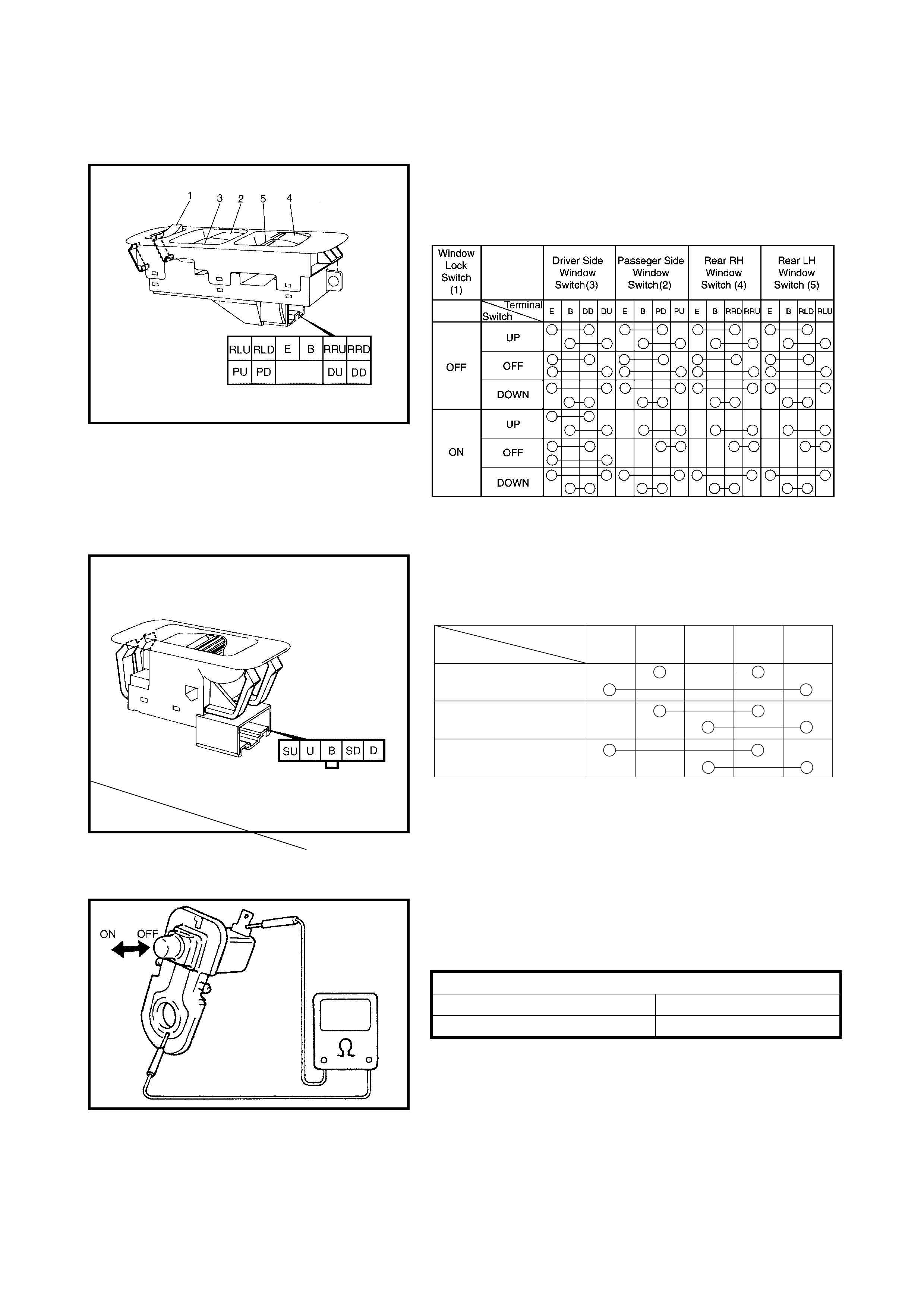
2.19 POWER WINDOW CONTROL SYSTEM
POWER WINDOW MAIN SWITCH
Inspection
Check for continuity between the terminals at each switch
position as shown below. If the check result is not as
specified, replace the switch.
POWER WINDOW SUB SWITCH
Inspection
Check for continuity between the terminals at each switch
conditi on as sh own bel ow.
If the check result is not as specified, replace the switch.
2.20 DOOR SWITCH
INSPECTION
Remove the door switch and check for continuity as
specified.
If found detective, replace the switch.
Terminal
Switch
Position
UP
BSDSUD U
OFF
DOWN
Door Switch Specification
OFF position (Door closed) No continuity
ON position (Door open) Continuity
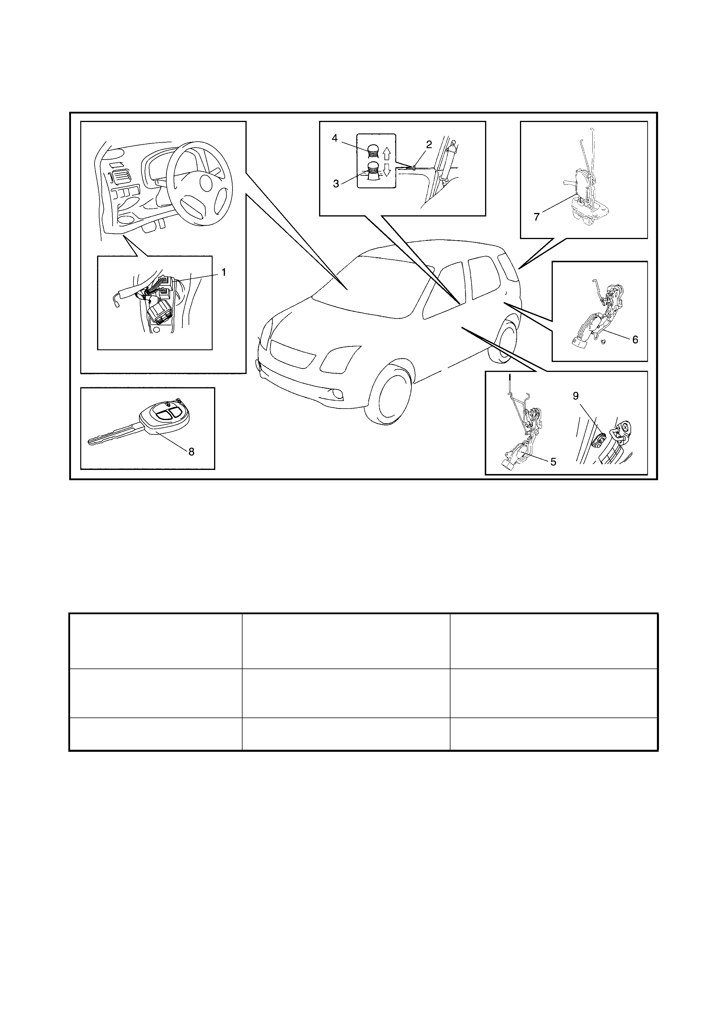
2.21 POWER DOOR LOCK SYSTEM WITH KEYLESS ENTRY SYSTEM
COMPONENT LOCATION
Legend
SYSTEM DESCRIPTION
The ke yless e ntry s ystem has the foll owing signal mod es in orde r to feed back the si gnal wh en the co ntrol ler
received LOCK and UNLOCK signals from the transmitter.
NOTE:
• These signal modes can be changed, refer to CHANGE OF SIGNAL MODE in this Section.
• The default condition is the hazard warning light signal mode.
CHANGE OF SIGNAL MODE
1. Confirm that all doors are closed and that the ignition key is out of the ignition switch.
2. Perform the following procedures within 15 seconds:
a. Insert, then withdraw the ignition key from the ignition switch.
b. Repeat Step a. two times.
c. Insert the ignition key in the ignition switch again then push the LOCK button on the transmitter more
than five times.
3. Confirm that the hazard warning light or interior light flashes once. The ‘change of signal mode’ is now
complete.
1. Power door lock controller 4. UNLOCK position 7. Back door actuator
2. Driver side door knob switch 5. Front door actuator 8. Transmitter
3. LOCK position 6. Rear door actuator 9. Door switch
Received Signal LOCK Signal UNLOCK Signal
Signal Mode
Hazard warning light signal
mode The hazard warning lights flash once. The hazard warning lights flash twice
and the interior light turns on for
about 15 seconds
Interior light signal mode The interior light flashes twice The interior light turns on for about
15 seconds
POWER DOOR LOCK SYSTEM OPERATION
Inspection
1. Check the following operation:
a. when the drivers side key cylinder is turned to
LOCK, check all doors lock.
b. When the drivers side door key cylinder is turned to
UNLOCK, check all doors unlock.
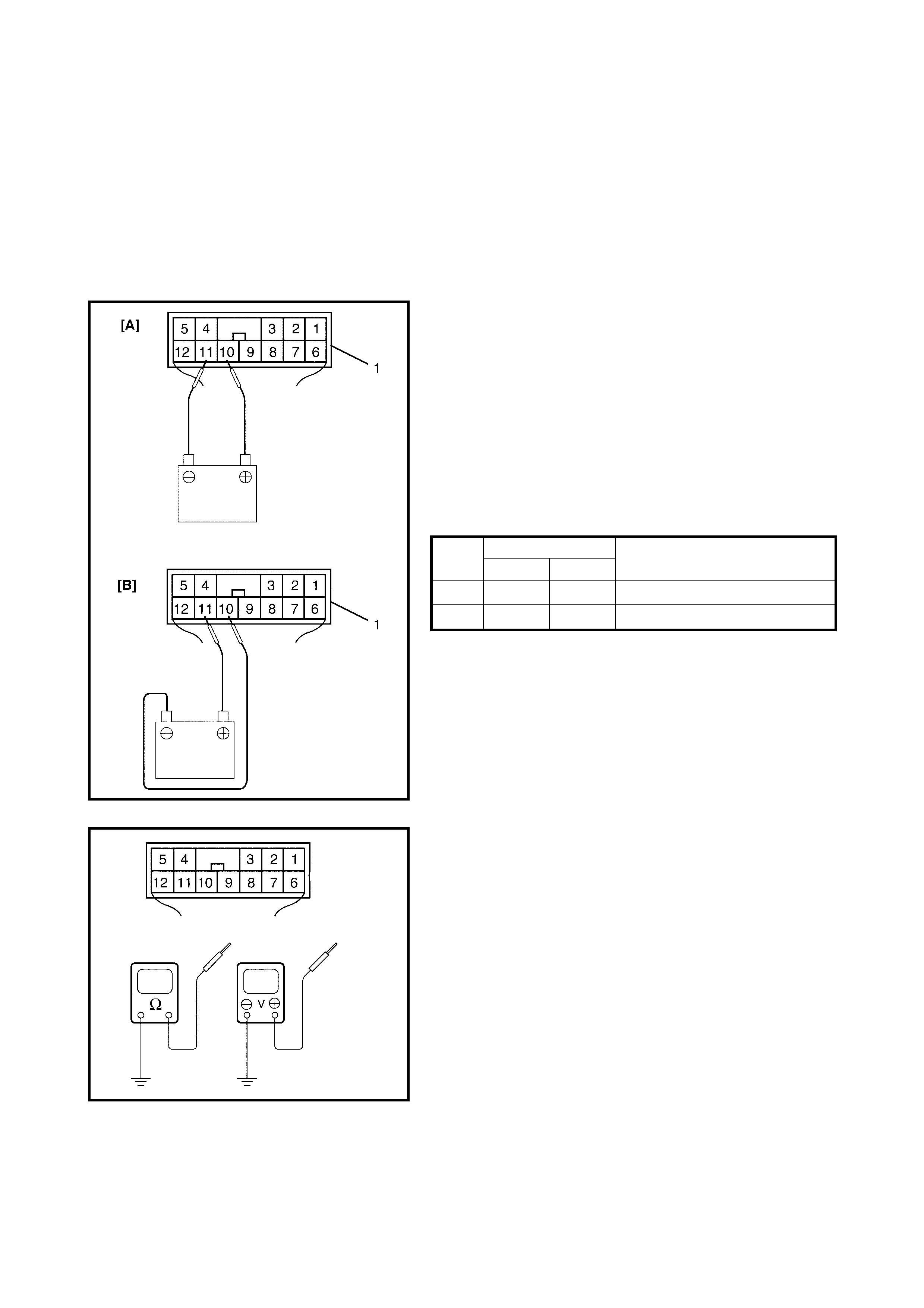
POWER DOOR LOCK SYSTEM CIRCUIT
Inspection
1. Disconne ct the negati ve (–) ca ble from the battery.
2. Disconnect the door lock controller coupler, G40 (1).
(Coupler is viewed from the harness side in the figure).
3. Confirm that all doors are unlocked. Connect battery
positive (+ ) and neg ative (–) terminals to the door lock
controller coupler terminals and check the power door
lock operation as follows:
If it does not op erate as speci fied c heck ac tuator, refer
to DOOR LOCK ACTUATOR in this Section. If actuator
is OK, repair applicable circuit.
POWER DOOR LOCK VEHICLE OPERATION
4. Connect negative (–) cable to battery.
5. Check that the voltage and continuity between the
following terminals and body ground are to
specification under each condition.
If check result is not as specified, check driver’s door
knob switch, refer to DRIVER’S DOOR KNOB
SWITCH. If driver’s side door knob switch is OK, repair
applicable circuit.
Step TERMINAL OPERATION
G40-10 G40-11
1 [A]
+–
UNLOCK — LOCK
2 [B]
–+
LOCK — UNLOCK
POWER DOOR LOCK SYSTEM CIRCUIT CHECK
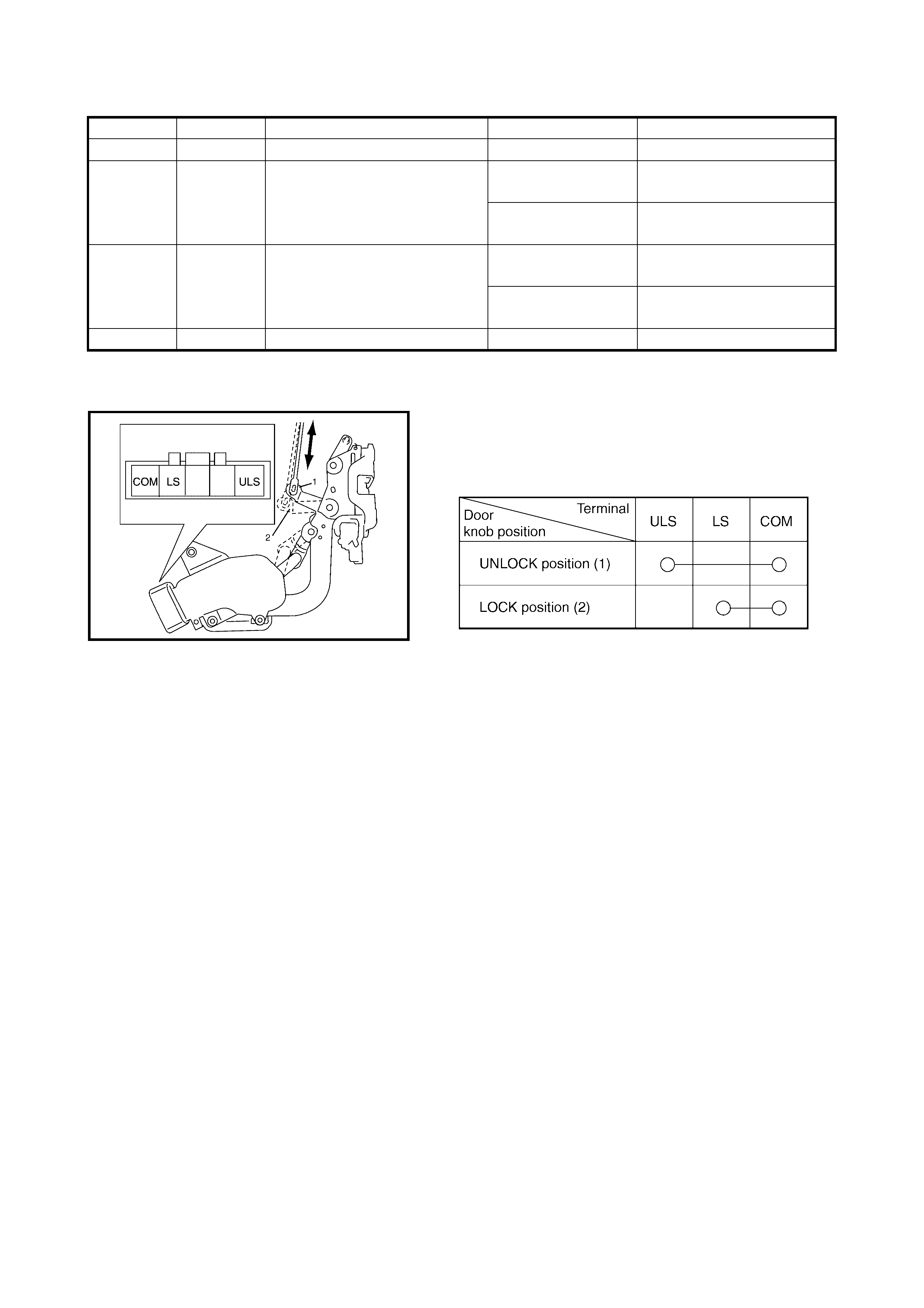
DRIVER’S DOOR KNOB SWITCH
On-vehicle Inspection
1. Remove the dr iver’s do or trim an d discon nect the door
lock switch connector.
2. Check for continuity as shown below between
terminals at each switch condition.
Terminal Wire Circuit Specification Condition
G40-7 WHT/GRN Main power supply 10 – 14 V –
G40-8 BRN Driv er s side door kno b switch
LOCK signal circuit
Continuity Driver s side d oor knob i s in
LOCK position
No Continuity Driver s sid e door knob is i n
UNLOCK pos iti on
G40-9 BRN/WHT Dr iver s si de door kno b swit ch
UNLOCK signal circuit
Continuity Driver s side d oor knob i s in
UNLOCK pos iti on
No Continuity Driver s sid e door knob is i n
LOCK position
G40-12 BLK Ground 0 – 1 V –
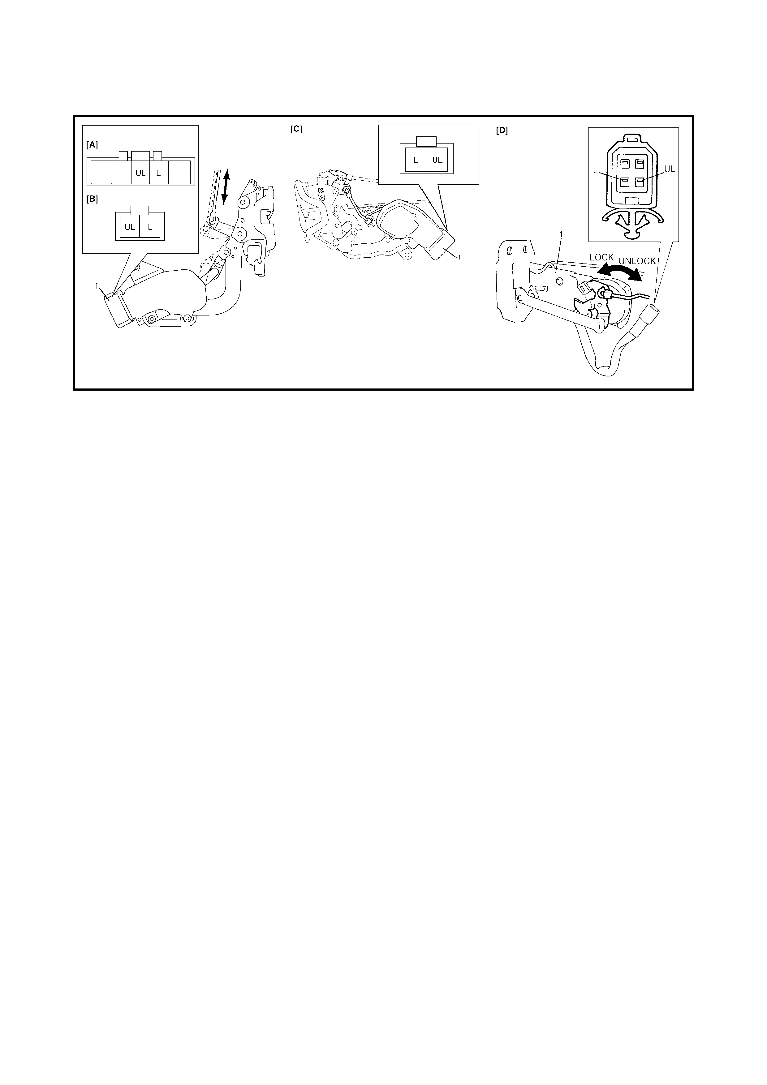
DOOR LOCK ACTUATOR
On-vehicle Inspection
Legend
1. Remove th e door tri m (front, r ear or b ack) and discon-
nect the door lock actuator (1) connector.
2. Connect battery (+) to terminal L and (-) to terminal UL.
Check that the door lock actuator (1) is in the LOCK
position.
If check result is not satisfied, replace the actuator.
3. Connect batte ry ( +) to term inal UL and (-) t o termi nal L.
Check that the door lock actuator (1) is in the UNLOCK
position.
If check result is not satisfied, replace the actuator.
[A]: Front Door Driver Side [C]: Rear Door
[B]: Front Door Passenge r Side [D]: Back Door
KEYLESS ENTRY SYSTEM OPERATION
Inspection
NOTE: If the keyles s entr y sy ste m is in ‘inter i or lig ht sig nal ’
mode, change it to ‘hazard warning light signal’ mode, refer
to CHANGE OF SIGNAL MODE.
1. Confirm that the power door lock system is in good
condition, refer to POWER DOOR LOCK SYSTEM
OPERATION in this Section.
2. Confirm that the turn signal and hazard warning light
system is in good condition, refer to 2.3 TURN SIGNAL
AND HAZARD WARNING LIGHTS in this Section.
3. Check the transmitter for a dead battery. Replace the
battery if it is dead, refer to TRANSMITTER in this
Section.
4. Confirm that all doors are closed and unlocked.
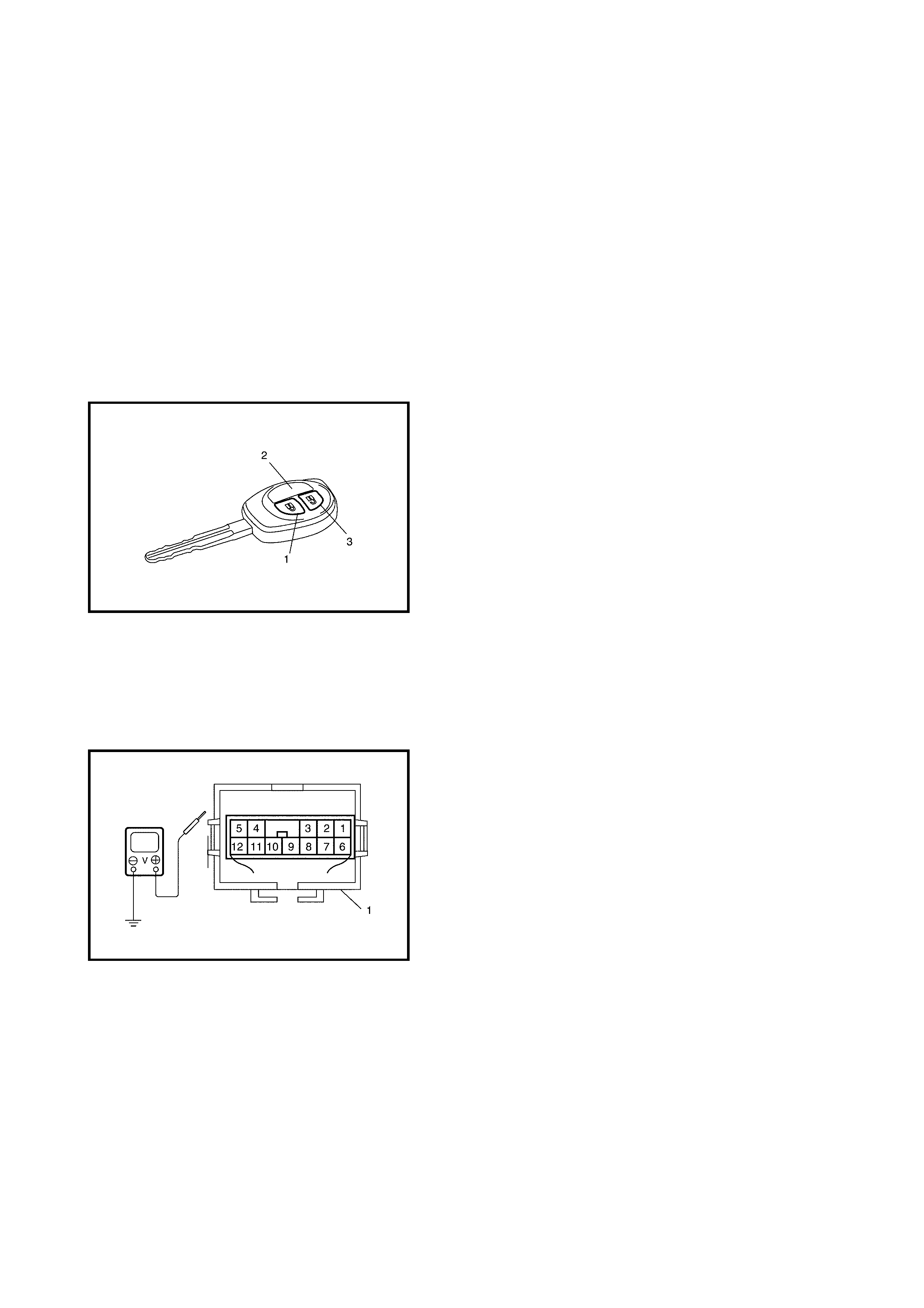
5. Check the following operation:
a. When pushing the LOCK button (1) on the transmit-
ter (2), check all doors lock and hazard warning
lights flash once.
b. When push ing UNLO CK butt on ( 3) on the tran smit-
ter (2), check that all doors unlock and the hazard
warning l ights flas h tw ic e an d the int erior ligh t tur ns
on for about 15 seconds with the interior light
switch in the middle position.
If the check result is not satisfactory, go to KEYLESS
ENTRY SYSTEM CIRCUIT – INSPECTION as follows.
KEYLESS ENTRY SYSTEM CIRCUIT
Inspection
NOTE: If the keyless entry syst em is in ‘interio r light signa l
mode’, change to ‘h azard warning light signal mode’, refer
to CHANGE OF SIGNAL MODE in this Section.
Check that the voltage and continuity between the following
terminals and body ground are to the specifications under
each condition.
If the che ck resul t is not as speci fied, check ap plicable ci r-
cuit.
If the circuit is normal, recheck the keyless entry system
circuit as follows:
1. Substitute a known-good door lock controller (1).
2. Register the key code, refer to CODE REGISTRATION
PROCEDURE in this Section.
3. Recheck the keyless entry system circuit.
KEYLESS ENTRY SYSTEM CIRCUIT CHECK
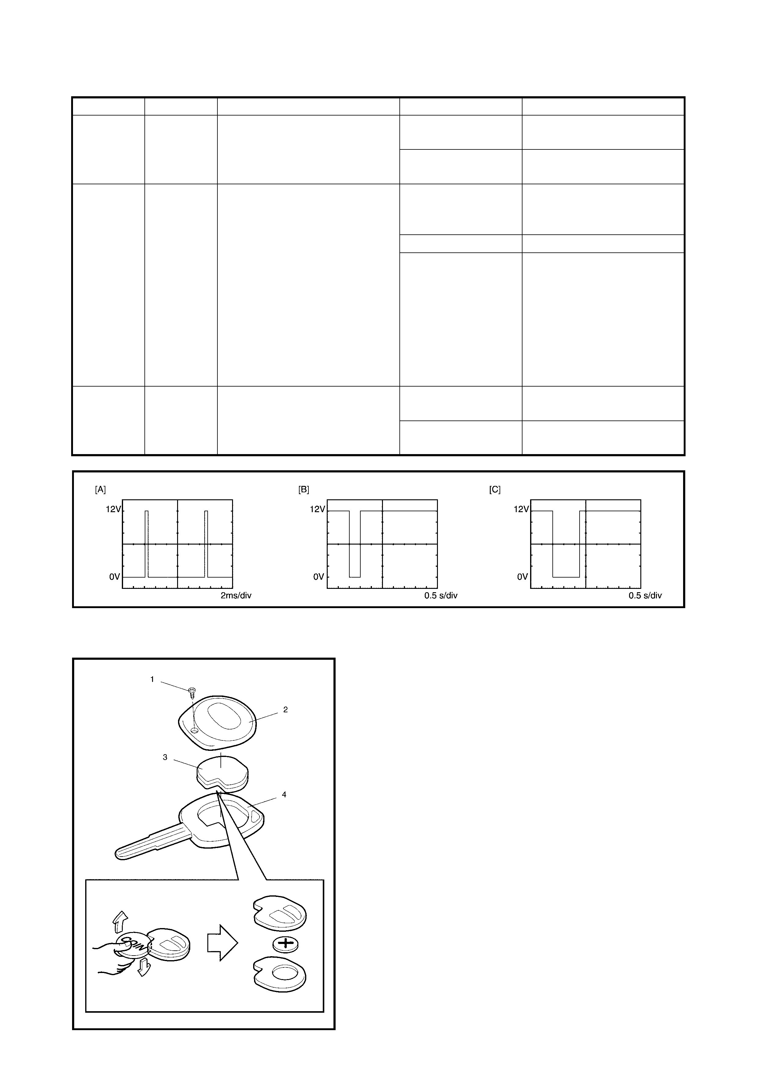
TRANSMITTER
Battery Replacement
If the tra nsmitter becomes unr eliable, r eplace the tr ansmit-
ter battery as follows:
1. Remove the screw (1) and transmitter cover (2).
2. Remove the transmitter ( 3) from the trans mitter holder
(4).
3. Put the edge of a coin or flat blade screwdriver in the
slot of the transmitter (3) and pry it open.
4. Replace the battery (lithium disc-type CR1616 or
equivale nt battery) so its
+
termin als faces ‘+’ mark on
transmitter.
5. Fit the transmitter together (3) and install it into the
transmitter holder (4).
6. Install the transmitter cover (2) and screw (1).
7. Make sure that the door locks can be operated with the
transmitter.
CAUTION: Do not allow the printed circuit board or the
battery to be contaminated with grease or dirt.
NOTE:
• To prevent theft, break the transmitter before discarding.
• Dispose of the used battery according to applicable
rules a nd regulations . Do not di spose of lithium batte r-
ies with ordinary household rubbish.
Terminal Wire Circuit Specification Condition
G40-2 BLU/YEL Key remainder circuit 10 – 14 V Ignition key is in ignition
switch
0 – 1 V Ignition key is not in ignition
switch
G40-4 BLK/RED Door switch & interior light
circuit
0 – 1 V Drivers side, passenger
side, rear passenger side
or back door is open.
10 – 14 V All doors are closed.
Figure [A]
• Fulfill the fol lowi ng
conditions:
• All doors are closed.
• Interior light switch is in
middle pos ition
• 15 seconds after pu shing
UNLOCK button on
transmitter.
G40-5 YEL/RED Hazard warning signal circuit Figure [B] Push the LOCK button on
the transmitter
Figure [C] Push the UNLOCK button
on the transmitter

CODE REGISTRATION PROCEDURE
If the transmitter or door lock controller is replaced with a
new one, register the key code as follows:
1. Confirm that the vehicle is the following condition:
• All doors are closed.
• Ignition key is out of ignition switch.
• Driver side door is unlocked, and the window is open
2. Disconnect negative (–) cable from battery.
3. After 30 seconds, perform the following procedure
within 60 secon ds....
a. Connect negative (–) cable to battery.
b. Operate the driver door snib to LOCK and then
from LOCK to UNLOCK twice.
c. Push the “LOCK” button on the transmitter and
confirm that all door snibs cycle.
d. Move the driver door snib to the “LOCK” position.
e. Push the “LOCK” button on the transmitter twice
and confirm that all door snibs cycle.
This completes the registration procedure.
NOTE:
• Two transmitter codes can be registered.
• If an attempt is made to register a third transmitter
code, the first one will be cleared.
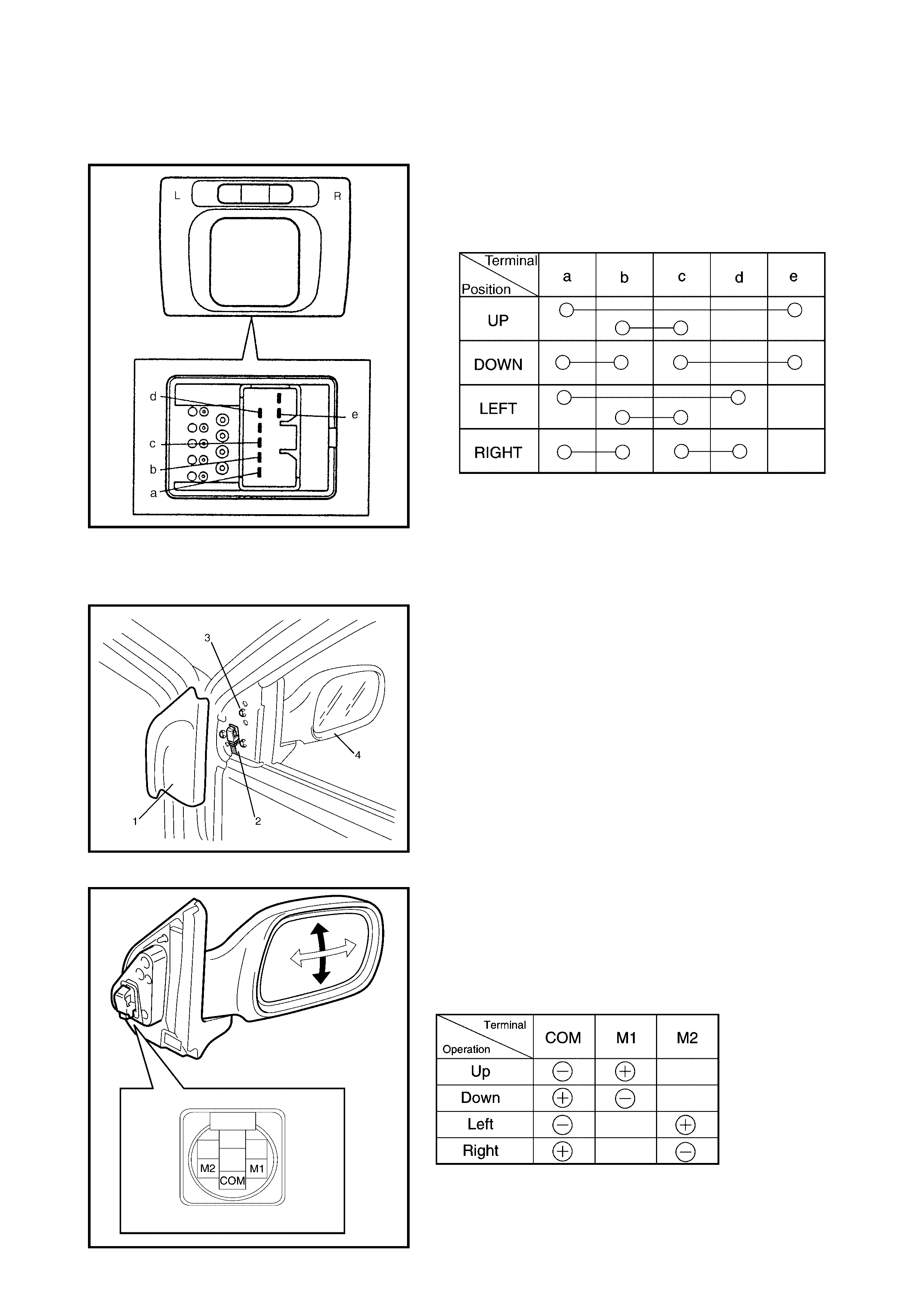
2.22 POWER DOOR MIRROR CONTROL SYSTEM
MIRROR SWITCH
Inspection
1. Remove the mirror switch from the instrument panel.
2. Check for continuity between terminals at each switch
position as show below.
If ch eck re sul t is not as sp ecif ied, repl ace m irr or sw itch.
2.23 DOOR MIRROR ACTUATOR
REMOVAL
1. Remove the garnish (1).
2. Disconnect the door mirror connector (2).
3. Remove the three door mirror mounting bolts (3) and
remove the door mirror assembly (4).
INSPECTION
Check that the door m irror operates properly when b attery
voltage is applied to the connector terminals as follows.
• Connect battery positive and negative to the door
mirror terminals shown below.
If it does not follow the table’s operation, replace door
mirror assembly.
CAUTION:
Never short positive and negative probes
to prevent wire harness from damage.
INSTALLATION
Revers e remo val p rocedur e to ins tall door mi rror a ssem bly
ensuring not to pinch the harness between the door and
door mirror.
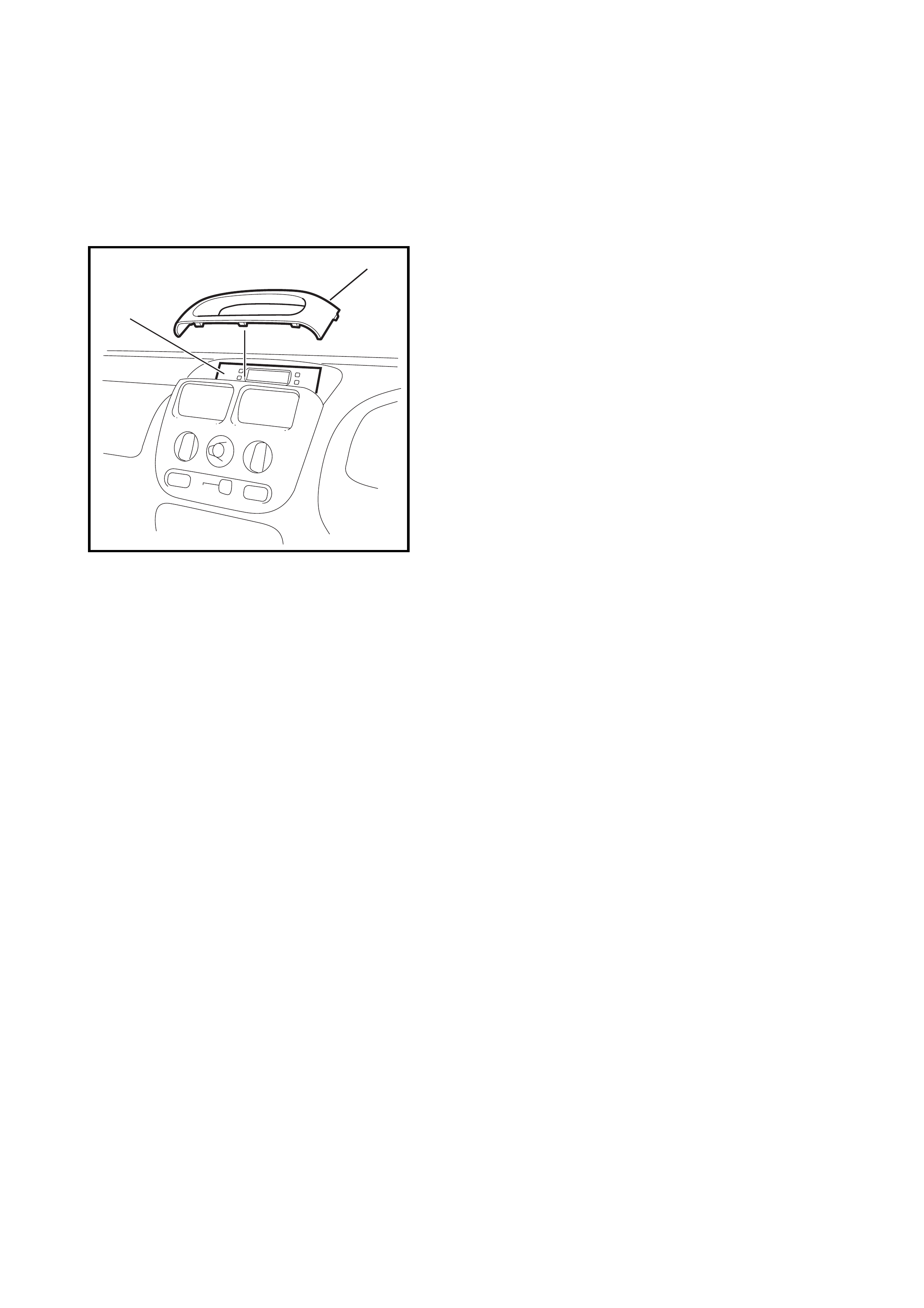
2.24 MULTI INFORMATION DISPL AY
REMOVAL
1. Unclip the centre-upper console (1) from the instru-
ment panel.
2. Remove the 3 multi information display mounting
screws.
3. Disconnect the multi information display coupler.
4. Remove the multi information display (2).
INSPECTION
Check the multi information display wire harness and
grounding, refer to 7.27 F-2 MULTI INFORMATION
DISPLAY in Section 8A CIRCUITS AND
CONNECTORS.
If the wire harness and connections are OK and the clock
still malfunctions, replace the multi function display.
INSTALLATION
The multi information display installation procedure is the
revers e of the removal.
1
2
YGM0817