
SECTION 8A1 - CIRCUITS AND CONNECTORS
(MY2004 UPDATE)
WARNING:
(For the vehicles with the Supplemental Restraint System (Airbags ) and/or the Seat Belt Pretensioner
System)
Service on or around the airbag system / Seat belt pretensioner system components or their wiring
must be performed only by an author ised Holden retailer. Observe all the warnings in the Service
Information and disable the systems before servicing on or around the components and the wiring
of the systems. Failure to follow the WARNINGS could result in unintende d activation of the systems
or could render the systems inoperative. Either of these two conditions may result in severe injury.
Precautions
General information
How to read connector layout diagram
How to read connector codes and
terminal nos
How to read ground (Earth) point
How to read power supply diagram
How to read system circuit diagram
Symbols and marks
Abbreviations
Wire / connector color symbols
Connector layout diagram
Engine compartment
A: Battery ground cable
C: Engine harness
E: Main harness
E: Main harness
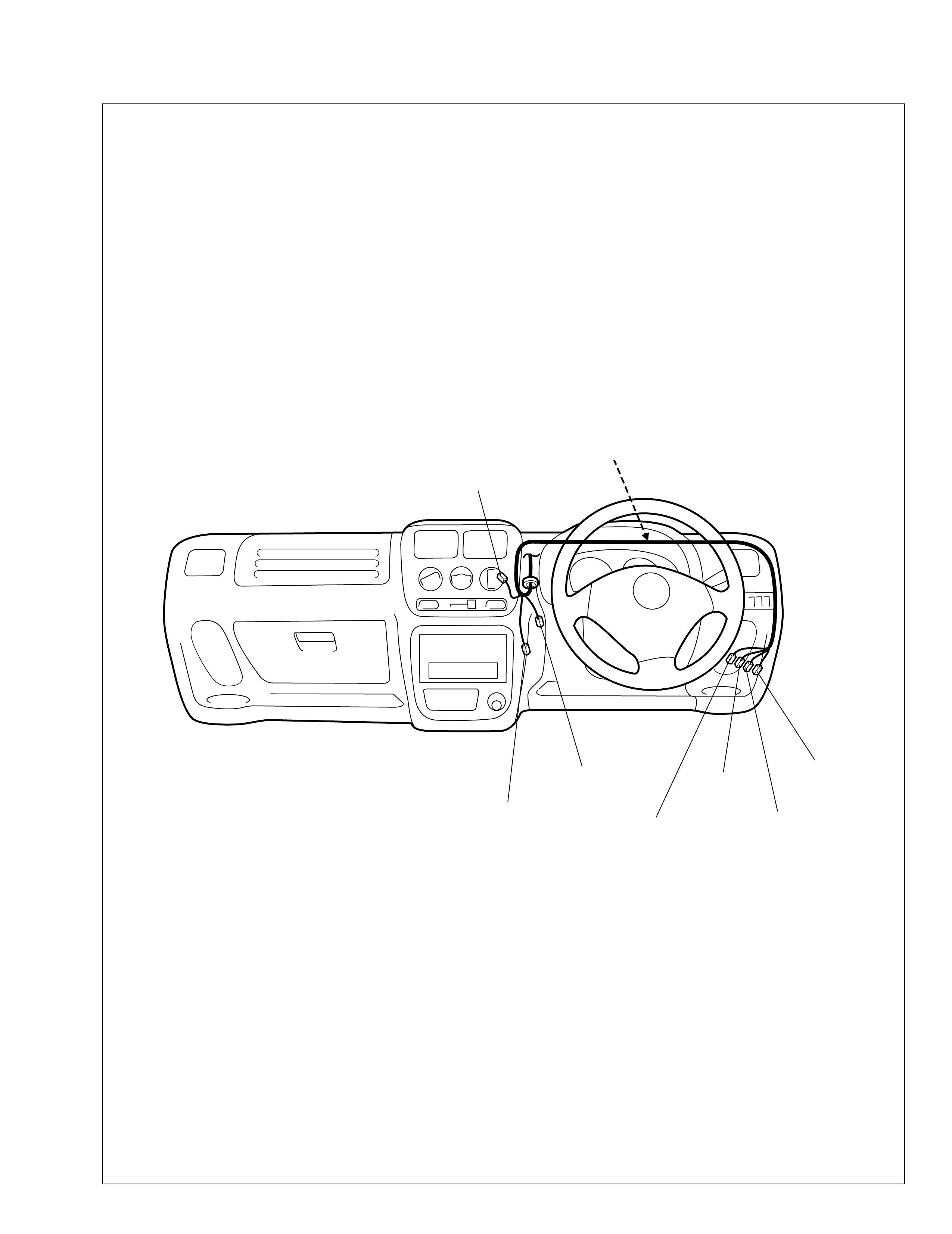
Instrument panel harness
G: Instrument panel harness
Powe r window main wire
J: Power window main wire, power
window sub wire, power window
rear wire
K: Dome light harness
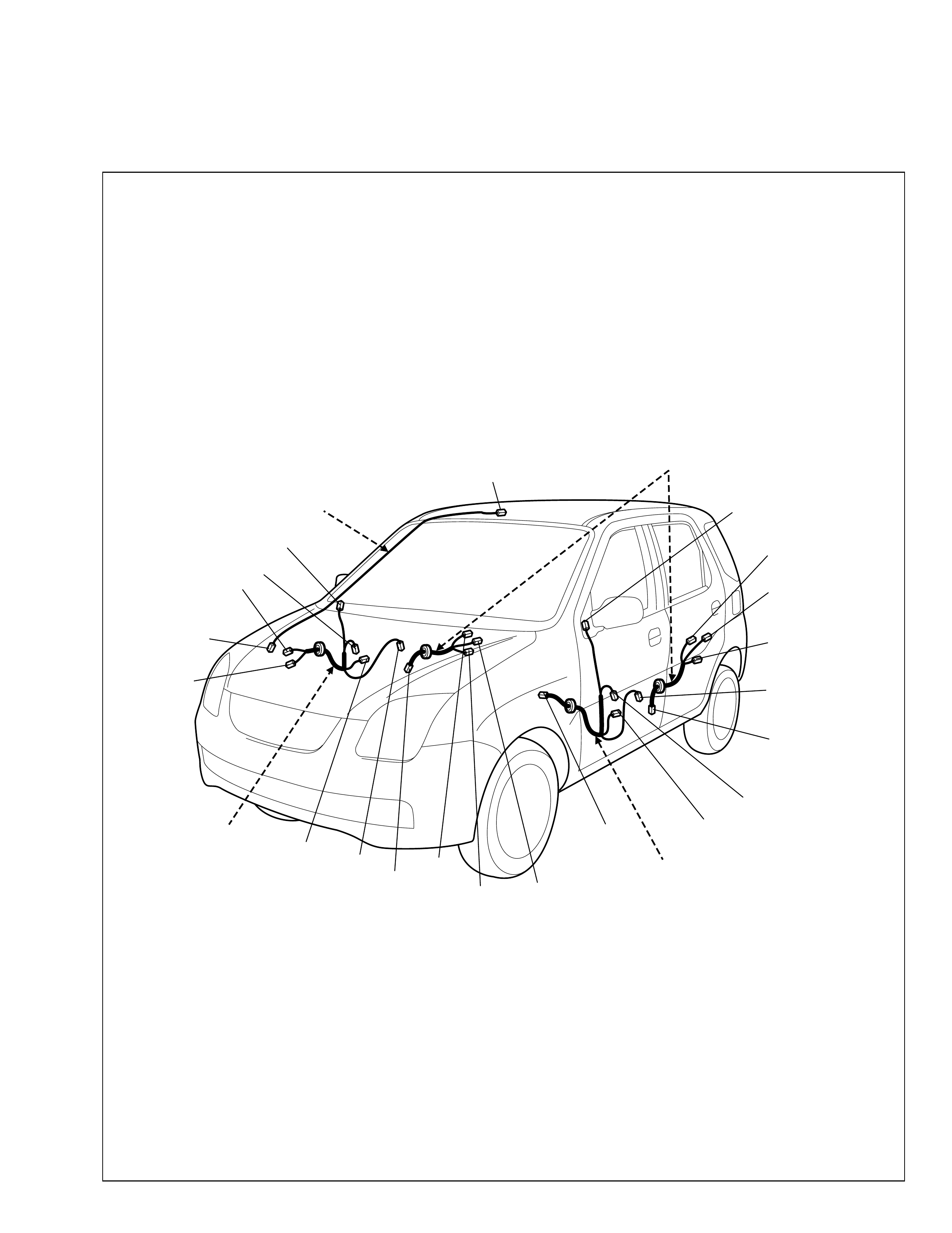
Rear speaker wire
K: Rear speaker wire
L: Floor harness, G sensor wire (4WD),
fuel pump harness
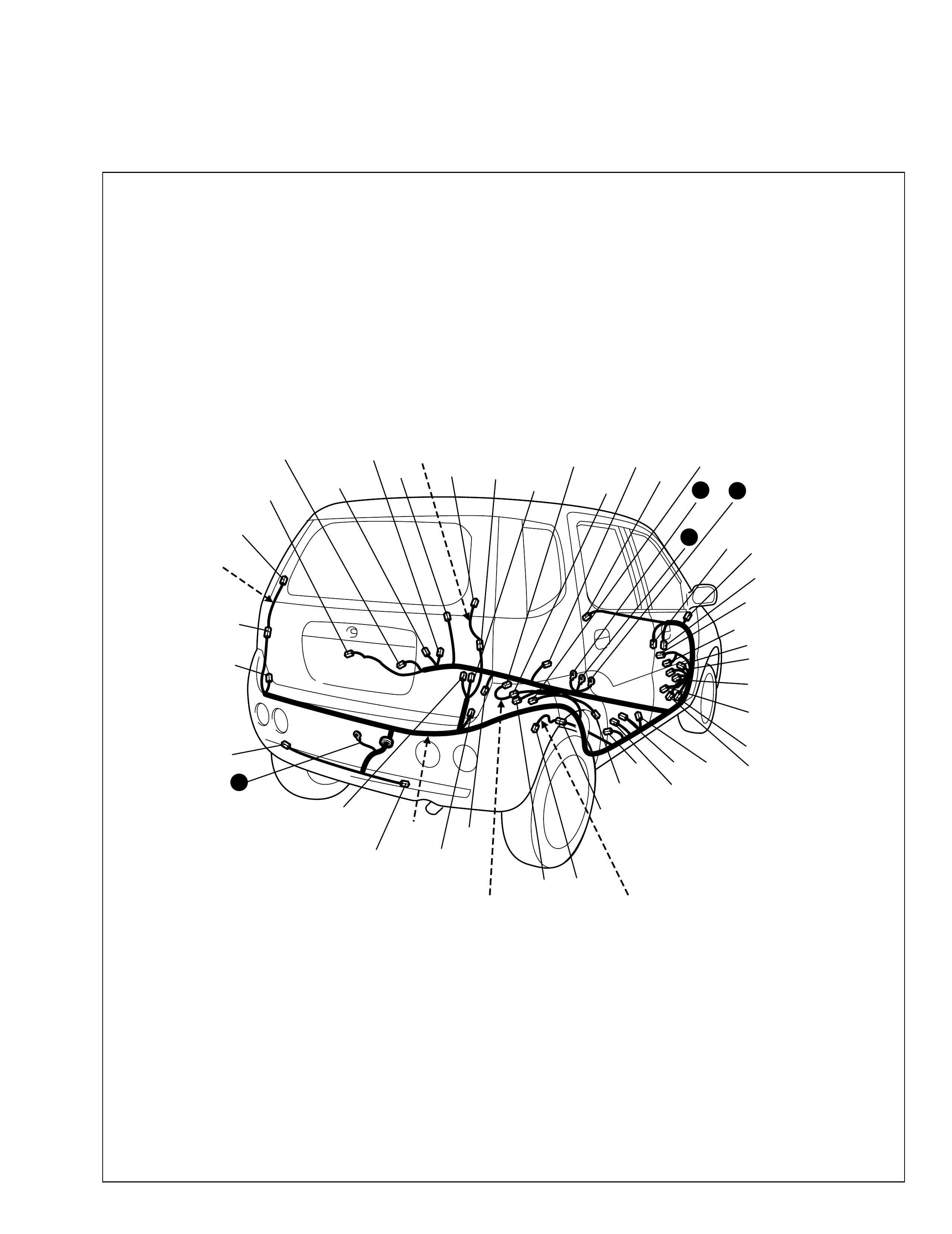
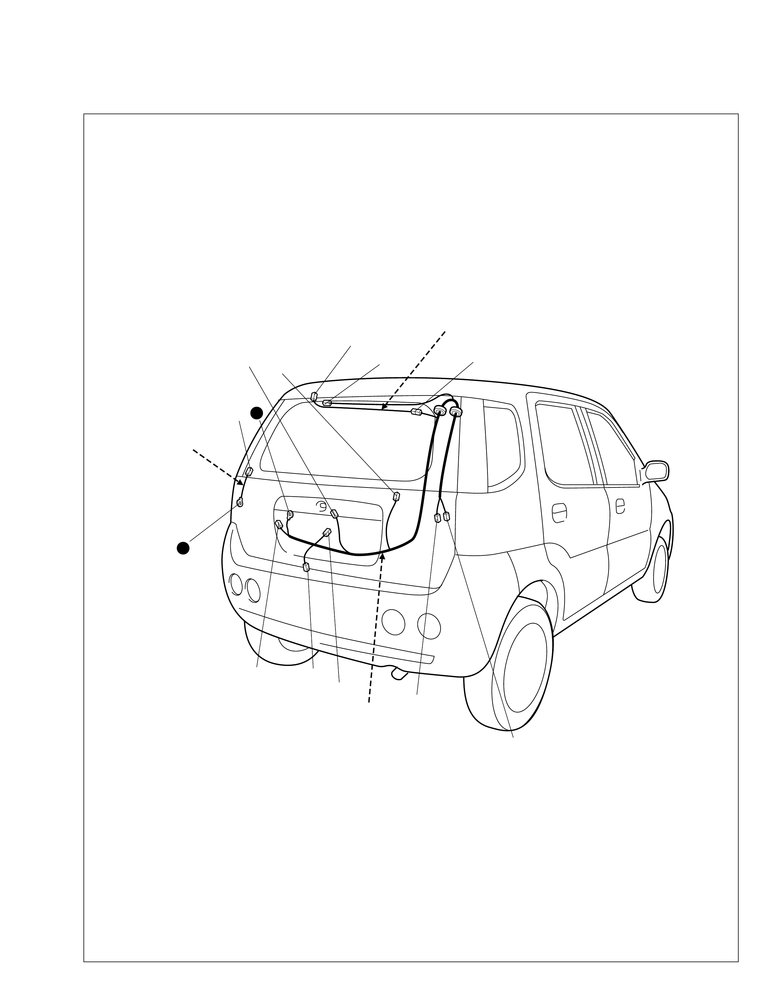
Rearend door harness
O: Rearend door harness, high
mounted stop light wire, rear
defogger wire
Main electronic control part location
Engine compartment
Instrument panel
Floor
Ground point
Engine compartment
Instrument panel
Floor
Power supply diagram
Power supply diagram
Fuses and the protected parts
Fuses in main fuse box
Fuse in circuit fuse box
System circuit diagram
A-1 Cranking system
A-2 Charging system
A-3 Immobilizer control system
A-4 Ignition system
A-5 Cooling system
A-6 Engine & control system
B-1 Windshield wiper & washer (with
intermittent wiper)
B-2 Rear wiper and washer
B-3 Rear defogger
B-4 Power window
B-5 Power door lock (With keyless entry)
B-7 Remote controlled mirror
B-9 Horn
C-1 Combination meter
C-2 Combination meter (indicator lamp)
C-3 Combination meter (warning lamp)

D-1 Headlight
D-3 Position, tail and license plate light
D-4 Fog light
D-6 Illumination light
D-7 Interior light
D-8 Turn signal and hazard warning light
D-9 Brake light
D-10 back-up light
E-1 Heater and air conditioner
F-1 Radio
F-2 Multi information display
F-4 Warning buzzer
G-1 A/T control system
G-3 Power steering
G-4 Air-bag control system
G-5 Anti-lock brake system
Connector list
C Connector
E Connector
G Connector
J Connector
K Connector
L Connector
O Connector
Precautions
• When disconnecting the battery terminals, be sure to (1) turn off the ignition switch and all other switches,(2)
disconnect the negative (-) terminal wire and then (3) disconnect the positive (+) terminal wire.Connect the
wires in the reverse order of disconnecting.
• When disconnecting the connectors, be sure to unlock the connector lock (if equipped) and then pull the
connector shells to detach them. Do not pull the wires.
• Connect the connectors by holding the connector shells. Make sure they are securely locked.
• Install the wiring harness securely without any slack.
• When installing parts, make sure the wiring harness is not interfered with or pinched by them.
• Avoid routing the wiring harness near or around a sharp corner or edge of the vehicle body or parts as much
as possible. If necessary, protect the wiring harness by winding tape or the like around on it.
• When replacing a fuse, make sure to use the specified capacity fuse. Using a fuse with a larger capacity can
cause damage to the electrical parts or a fire.
• Do not handle electrical/ electronic parts (computer, relay, etc.) roughly or drop them.
• Do not expose electrical/ electronic parts to high temperature (Approximately 80°C(176°F) or higher) or
water.
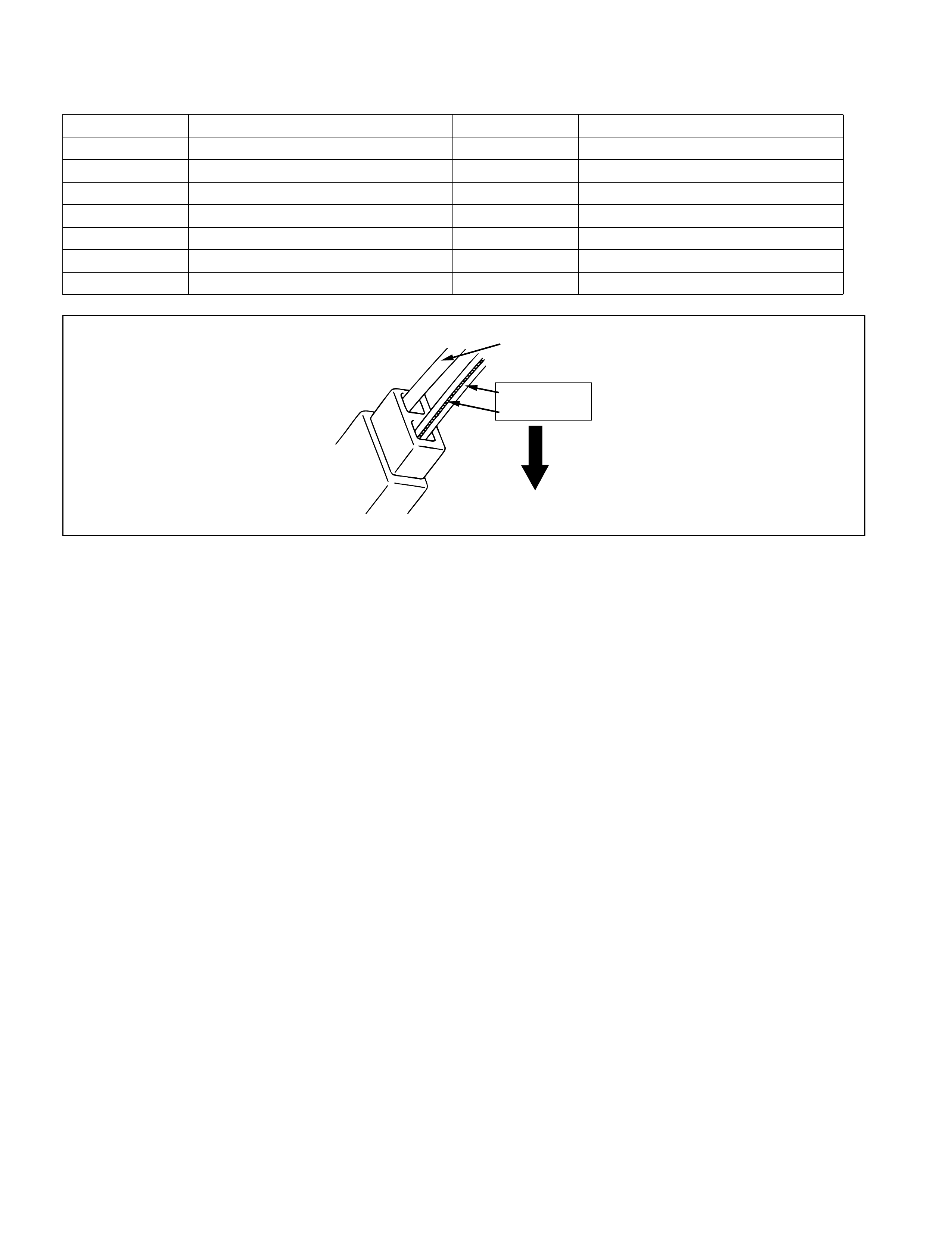
• Be sure to insert the tester probe into the wiring harness side of the connector for inspection.
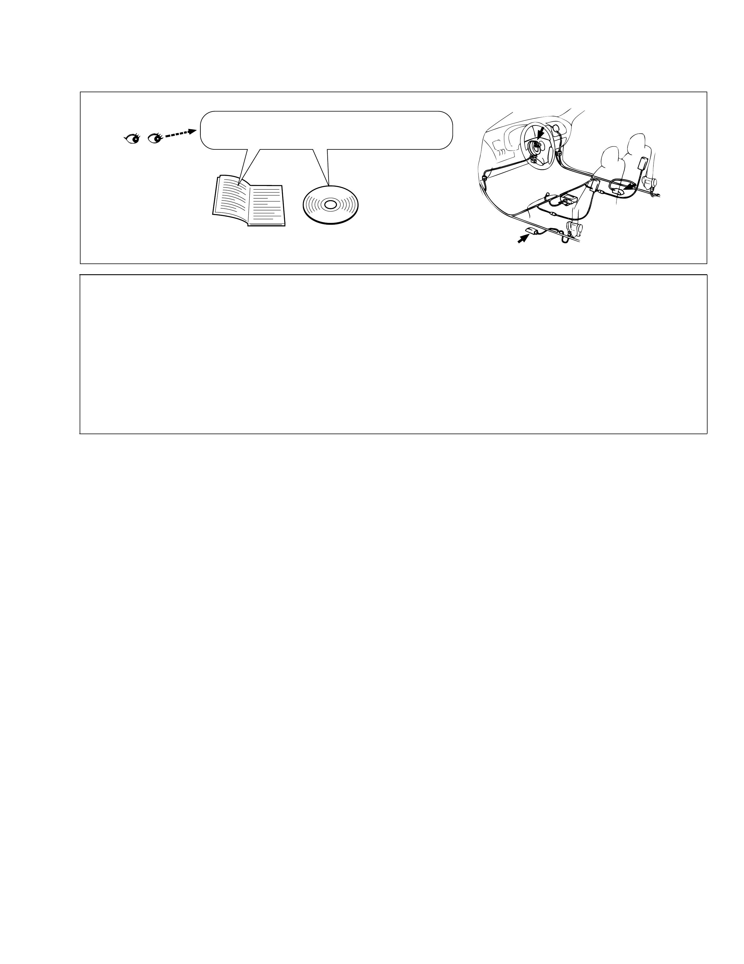
Air bag/seat belt pretensioner Warnings
Service manual
EXAMPLE
CD
WARNING:
(For the vehicles with the Supplemental Restraint System (Air Bags) and/or the Seat Belt Pretensioner
System)
Service on or around the air bag system / Seat belt pretensioner system components or their wiring
must be performed only by an authorized GM Holden dealer. Observe all the warnings in the service
manual and disable the systems before servicing on or around the components and the wiring of the
systems. The service manual(s) is (are) mentioned in the FOREWORD of this manual. Failure to follow
the Warnings could result in unintended activation of the systems or could render the systems inoper-
ative. Either of these two conditions may result in severe injury.
CAUTION:
To prevent damage to the electrical/ electronic parts (especially computers or semi-conductors) or to
preven t fir e.
99512-70 H 10-G H E.book Page 1 Friday, Sept ember 26, 2003 3:16 PM
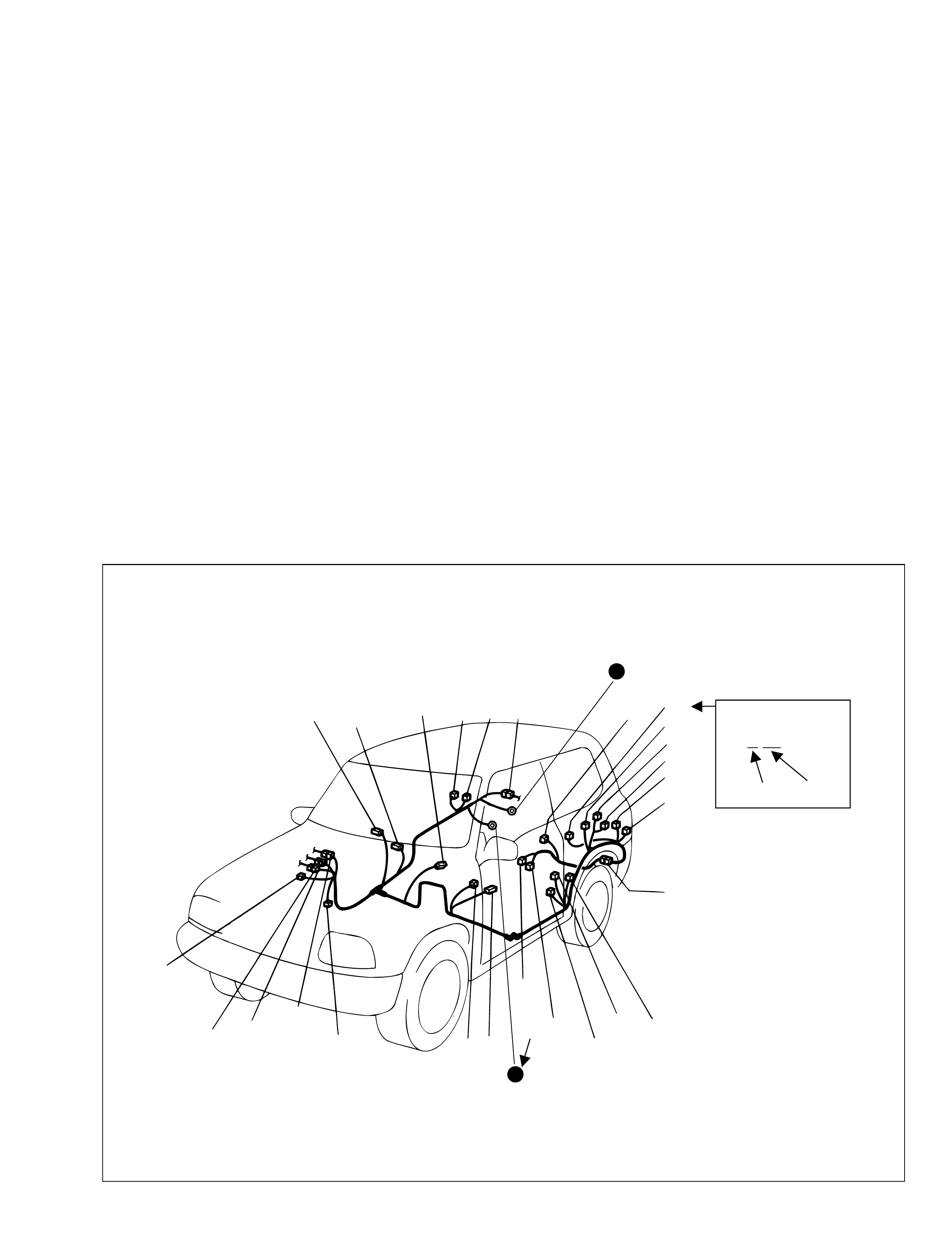
General information
How to read connector layout diagram
[A- 1]:H arness symbol and correspondi ng har n ess name
A: Battery harness
B: A/C harness
C: Engin e harness
D: Injector harn ess
E: Main harness, Oil pressure switch wire, Console wire
G: Instr u me nt panel harnes s
J: Side doo r w ire (P ow er w ind ow)
K: Interior light harness, Rear speaker wire, Roof wire
L: Floor harness, G sensor wire (Fuel pump harness)
M: R ear bumper harness
O: Rearend door harness
Q: Air bag/Pretensioner harness
R: (Fuel pump wire)
[A-2]:Connector Number
[B] : Ground (earth) point No.
12
11
[B]
[B]
Connector code
[A-1] [A-2]
L 36
L13
L15
R01
L14
L12
L11
L10
L09
L36
R02
L24
L25
L33
L28
L20 L26 (TO O01)
{
L05
L16
L32
L19
L01 (TO G01)
L02 (TO E04)
L03 (TO E05)
L42
R05
R04
L07 (TO K02)
99512-70 H 10-G H E.book Page 1 Friday, Sept ember 26, 2003 3:16 PM
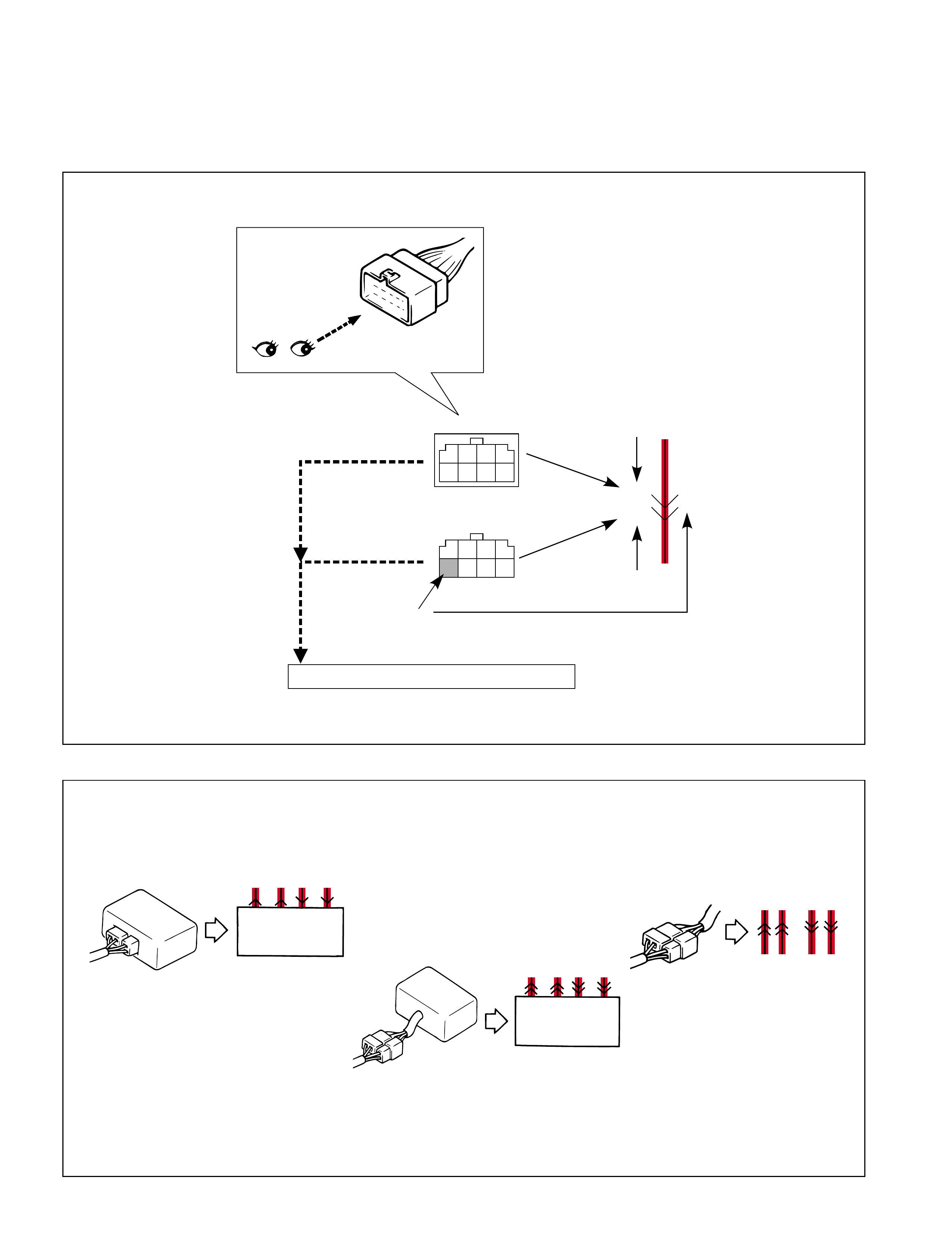
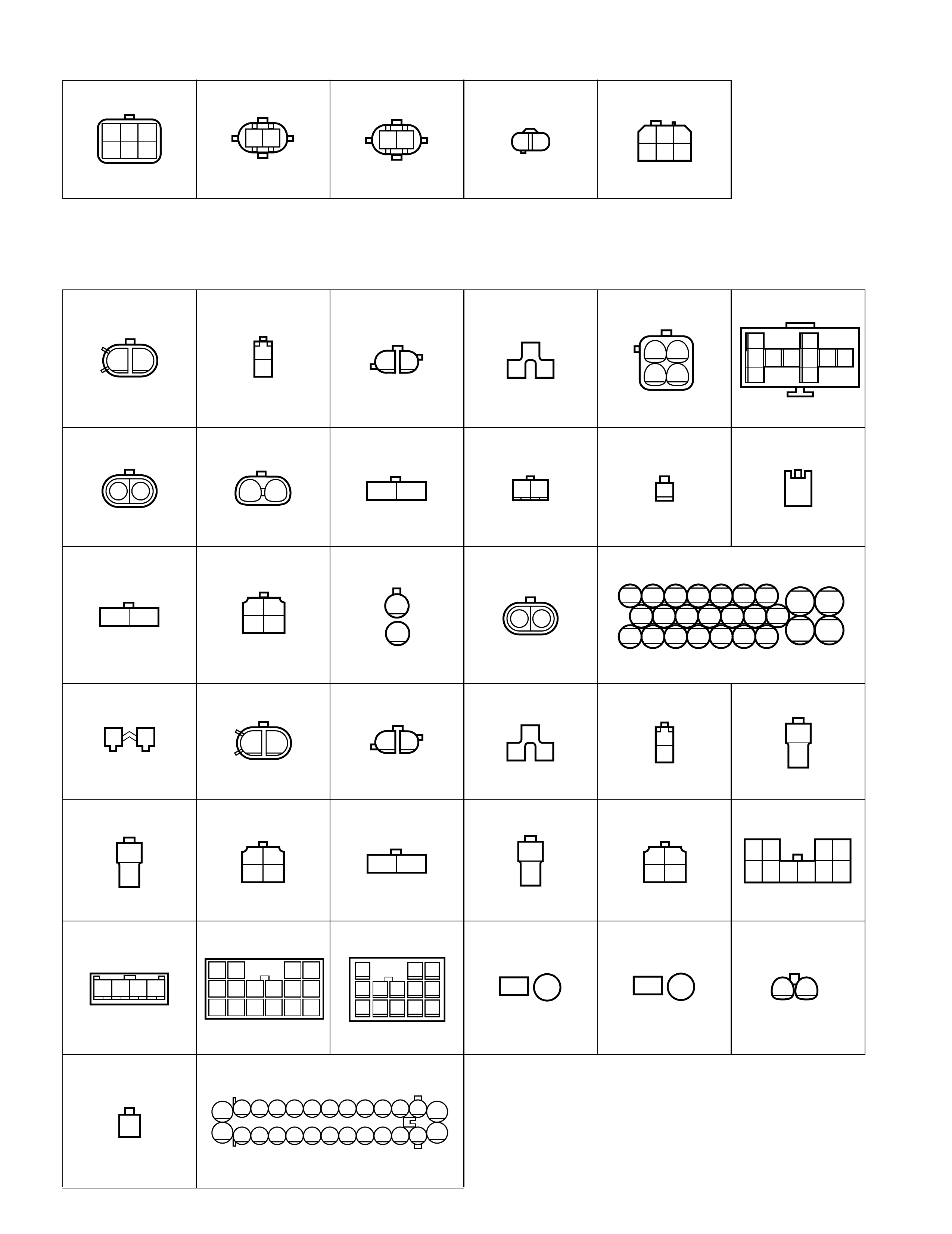
How to read connector codes and terminal nos.
1) Connector cod e/Terminal No./Termi nal layout
•The co nnecto r shape and termina l layout shown in th is ma nual are th ose when viewed from “Z” in the illus-
tration.
2) Connector type
A40
(View Z)
(View Z)
1
1234
5678
234 5678
D18 5
D18
A40 Connector code.
Connector code.
Terminal No.
Section 8A-8 ("CONNECTOR LIST")
Male terminal
Female terminal
Z
View Z
99512-70 H 10-G H E.book Page 2 Friday, Sept ember 26, 2003 3:16 PM
3) Terminals in one connector (Broken line) (B15)/Terminals in different connectors (B14,B16)
4) Joint connector (J/C)
•The joint connector (J/C) connects several different wires with the same wire color at one place instead of
connec ti ng the m by weldin g o r ca ulki n g o ne by one.It is n ot an ord ina ry c onn ect or but a p art o f th e c ont i nu-
ous wire in the harness.
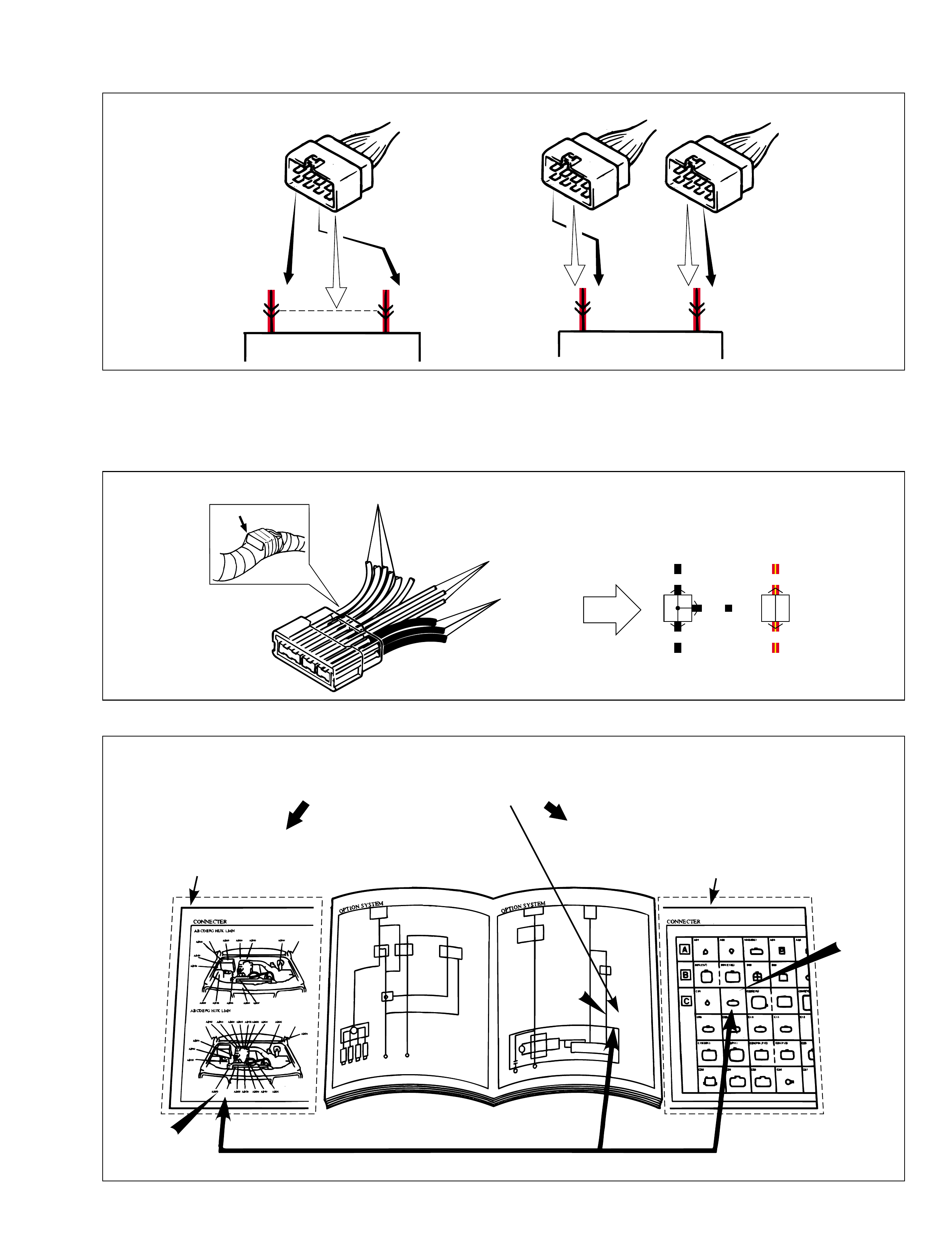
5) Connector location, shape and terminal No. of the
B15
B15 B14 B16
57 B14 B16
57
BLK BLK
RED/YEL
WHT/BLK
BLK
BLK
RED/YEL
RED/YEL
Example
Section 8A-7
("SYSTEM CIRCUIT DIAGRAM")
-Connector code and terminal No.
Section 8A-3
("CONNECTOR LAYOUT DIAGRAM")
-Connector location.
CROSS-REFERENCE
Section 8A-8
("CONNECTOR LIST")
-Connector shape and terminal position.
C02
C02
C02
C02
C02
C02
99512-70 H 10-G H E.book Page 3 Friday, Sept ember 26, 2003 3:16 PM
How to read ground (Earth) point
How to read power supply diagram
10
8
13
9
Section 8A-7 ("SYSTEM CIRCUIT DIAGRAM")
Section 8A-5 ("GROUND (EARTH) POINT")
CROSS-REFERENCE
Windoshield
washer
motor
Fuse box
20
15A
Windoshield
wiper
motor
E40
E09 E20
16
2
1
Off
On
Circuit
breaker
60A-B003-
YEL/BLU
1
20 5
21 3 4
6 7
BLU/BLK
BLK
10
BLK
BLK
9
10
10
BLK
M
BLU BLU/WHTBLU/RED
M
Device body grounding is not given the ground point number.
Connection to the system
indicated.
Section 8A-6 ("POWER SUPPLY DIAGRAM") Fuse box
- +
1
Battery
80A
23
15A
24
15A
7
15A
7
15A
33
25A
A
50A 30A 60A
BLK
YEL/BLK
PNK/BLK
LT GRN
YEL/GRN
YEL/BLUBLK/WHT
WHT/BLK
WHT/GRN RED
GRN
WHT YEL
BLU/RED
Fuse
box
Main fuse
Cassette
fuse
11
11 12 13 14 15 16 17 18 19 20 21 29 32
12 13 14 15 16 17 18 19 20 21 32
15A 15A 15A 20A 20A 15A 15A 15A 15A 15A 15A 15A
E44 321
B01 1E45 1E40 21
Fuse
box RED/YELYELWHT/GRN
Fuse 15A 15A
13 17
Section 8A-7
("SYSTEM CIRCUIT DIAGRAM")
Fuse number
12
99512-70 H 10-G H E.book Page 4 Friday, Sept ember 26, 2003 3:16 PM
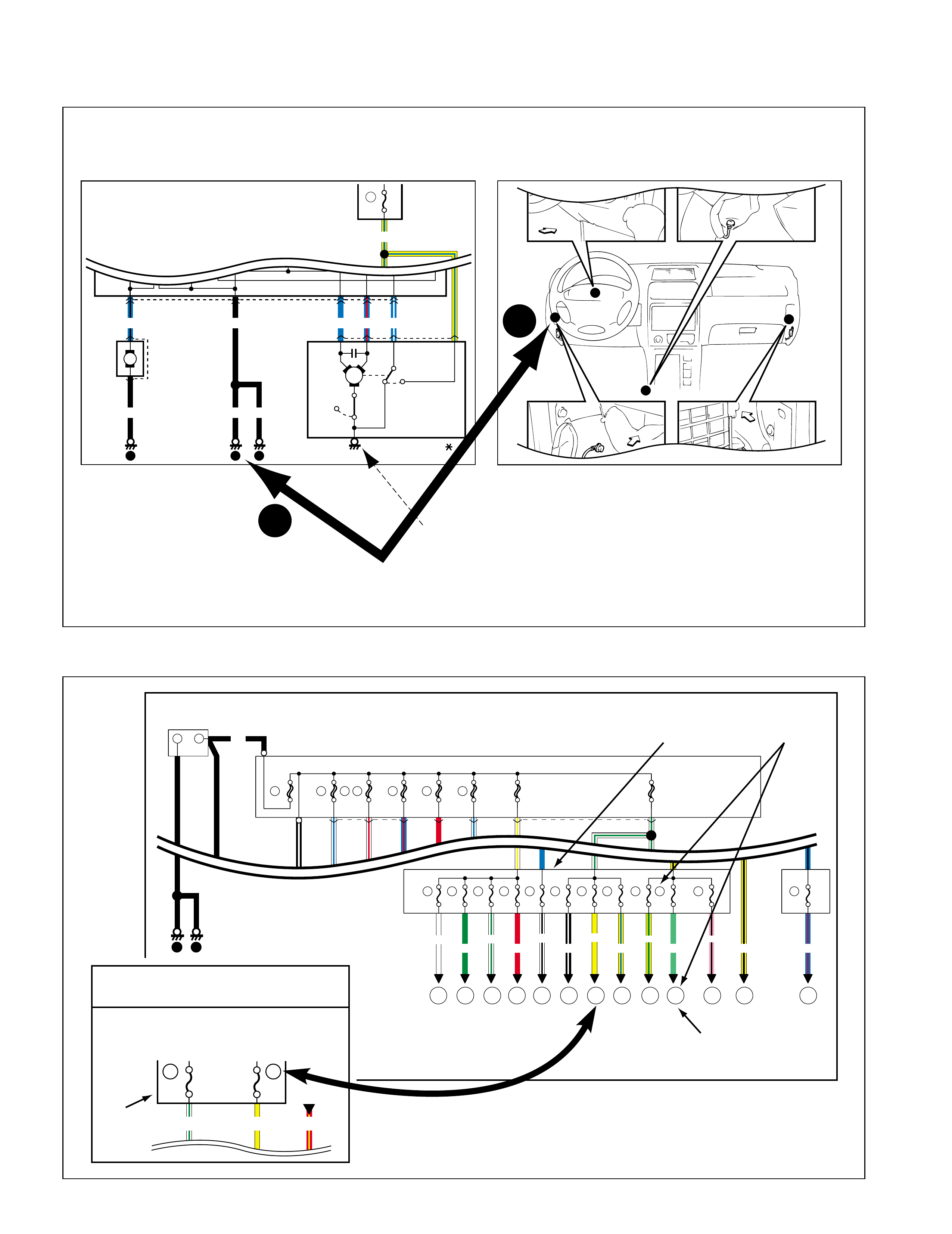
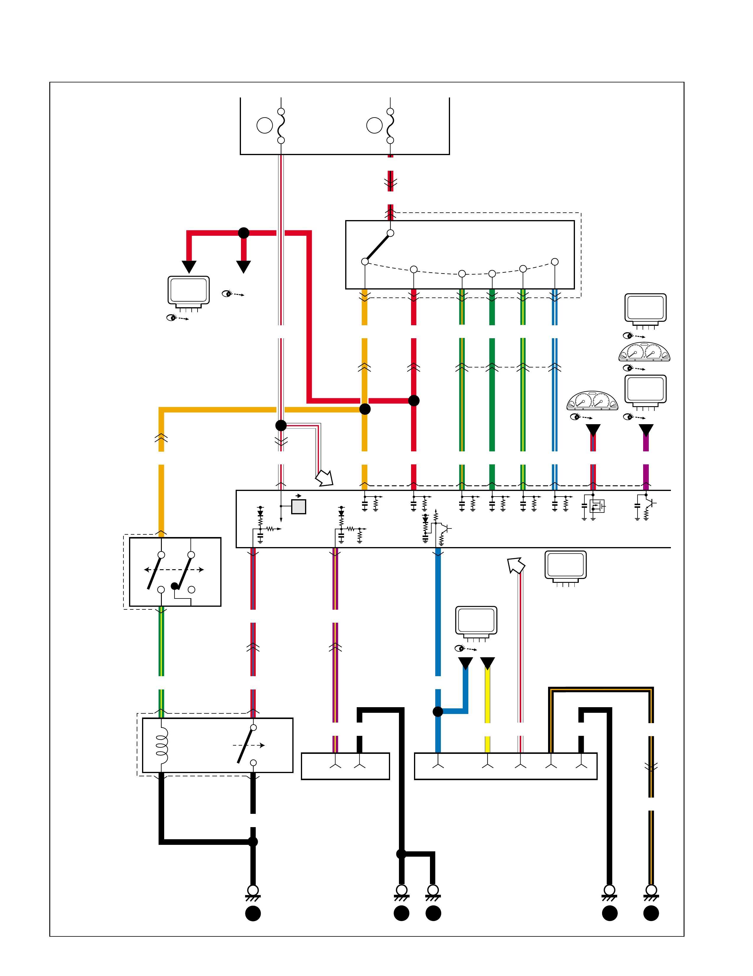
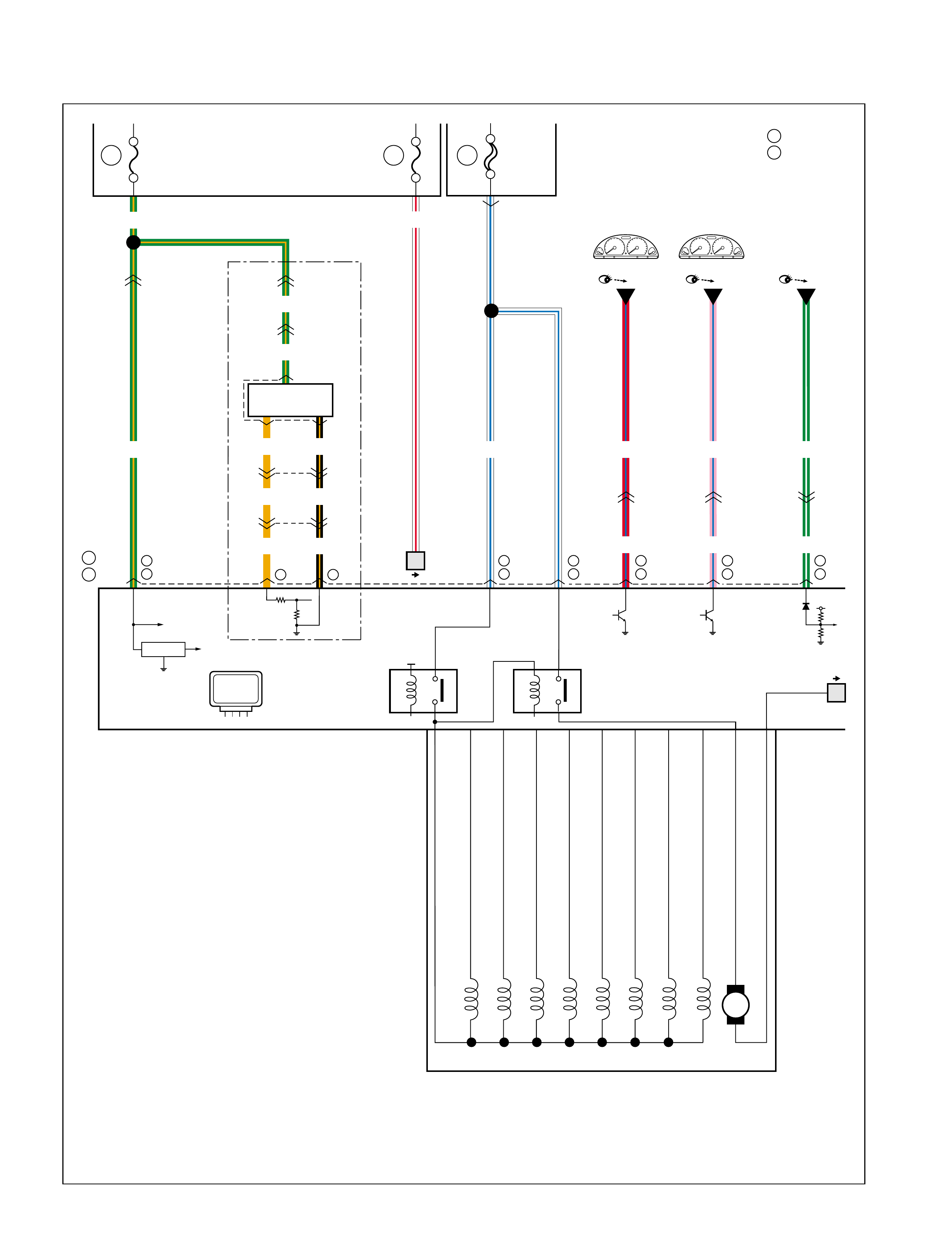
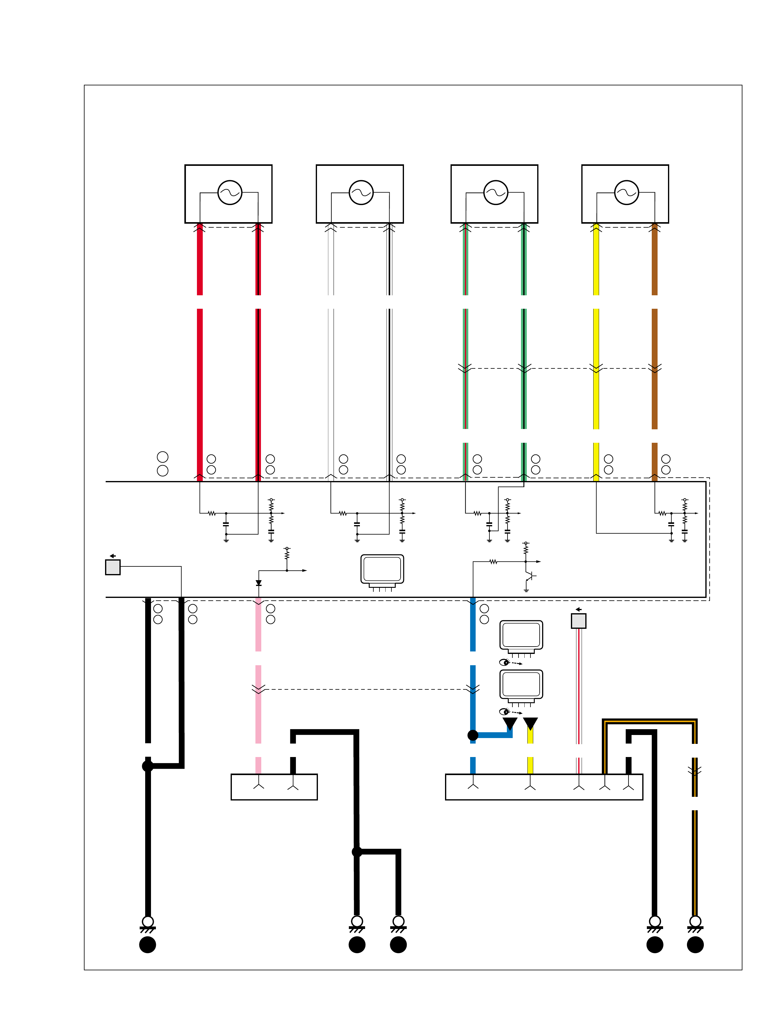
How to read system circuit diagram
The circuit diagram is designed so the current flows from the top of the diagram (power source) to the bottom of
the diagram (ground (earth)) as if giving an image of water flow.
[A]: Fuse No.
[B]: Circuit jumping page / direction
(See NOTE below for the details)
[C]: Circuit jumping point / direction
(See NOTE below for the details)
[D]: Terminals-in-one-conector mark
[E]: Wire color
[F]: Shield wire
[G]: Gr ound point
[H]: Specification variation
The white arrow between A an d B means “or”.
[I]: “From”
[J]: “To”
[K]: Connector code
[L]: Terminal No.
[M]: Symbol mark
[N]: “SEE” mark
Switch
BLU
BLU
GRN/BLK
GRN/REDGRN/BLK
1
2
GRN
GRN
C26 2
1
BLK
5
BLK
2
1
C40
GRN/BLK
"XX"
Solenoid
Fuse box
3
15A
Main
relay
ON
OFF
Fuse box
1
15A 6
20A
1
BLK
Sensor
12
8
BRN/RED
E52 1
2
E52 1
BRN/RED
RED
2
BRN/RED BRN/RED
Motor
M
M
65
5
A
B
A
B5
6
1
25 6 4 6
4-DOOR
2-DOOR
2
C71
E03
E34
O06
C31
E19
[A]
[B]
[C]
[F]
[G]
[D]
[H] [J] [K]
E33 7 5
E34 1
21
43
E08
ORN WHT BLK
RED
4
3
YEL
BLK/RED
ORN
GRN
GRN
BA
GRN
GRN
2
XX
Cont.M
[I]
[E]
[M] [N][L]
99512-70 H 10-G H E.book Page 5 Friday, Sept ember 26, 2003 3:16 PM

NOTE:
[B]Circuit jumping page / direction
This means “Jump to the page directed with the arrow(s) by their number.(For example:” Tw o a rr o ws
dir ect ing lef t” means” Jump to two pages before”.)
You will find the same symbol with the arrows directing opposite in the referenced page.
The circuit continues between the symbols.
[C]Circuit jumping point / direction
The circuit continues to the same symbol with opp osite direction within the page.
You will find the other symbol in the direction of the arrow.
99512-70 H 10-G H E.book Page 6 Friday, Sept ember 26, 2003 3:16 PM
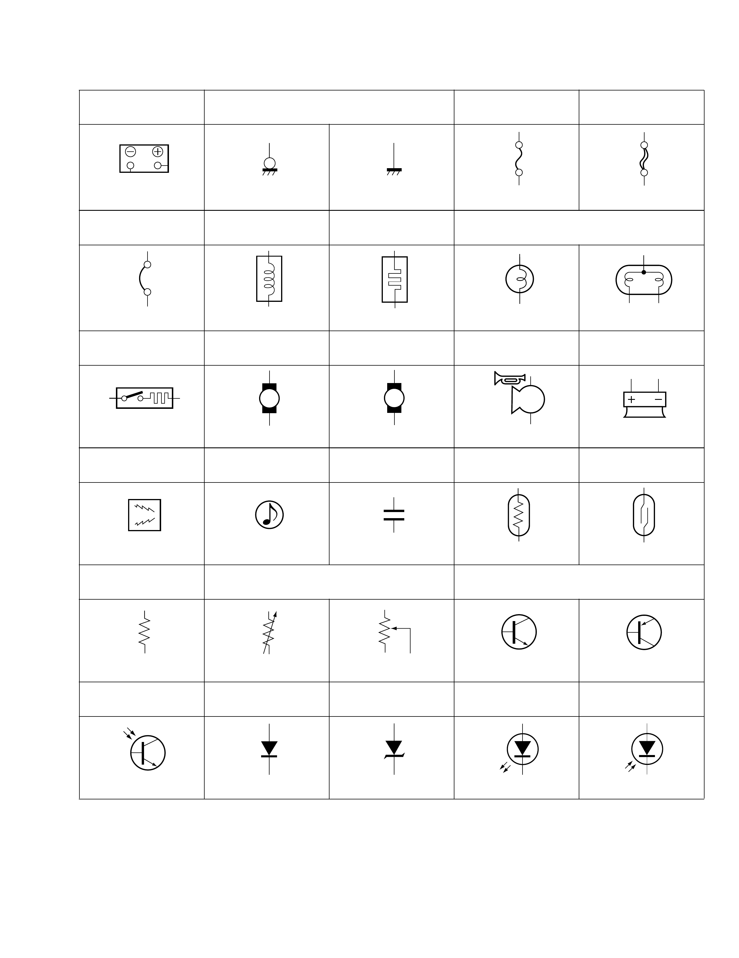
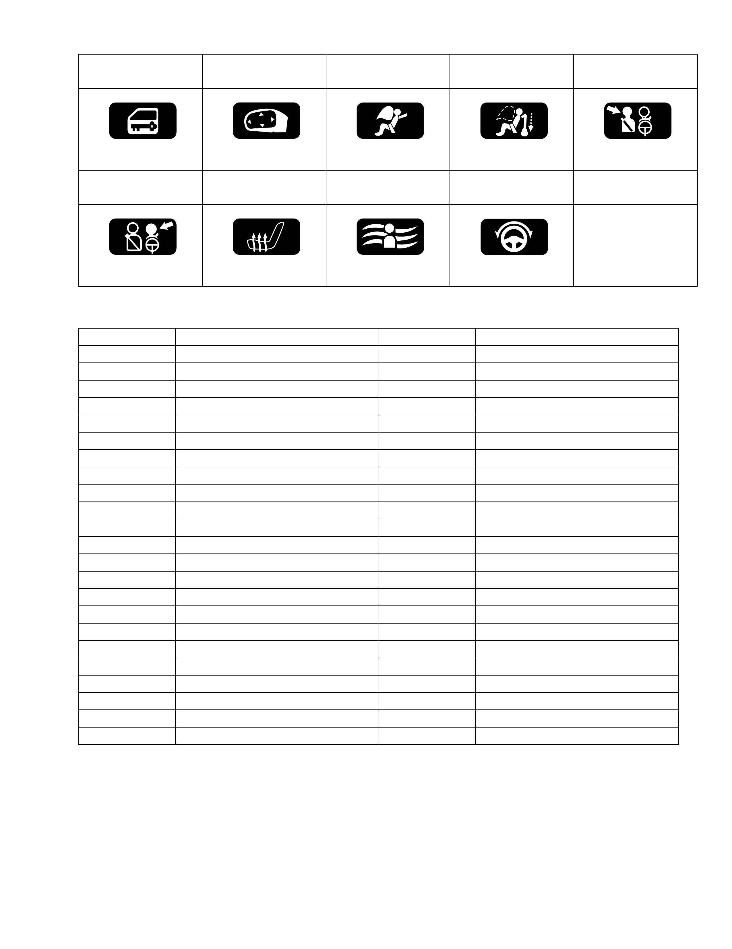
Symbols and marks
Battery Ground Normal fuse Slow blow fuse
Circuit break er Coil, Solenoid Heater Bulb
Cigarette lighter Motor Pump Horn Speaker
Bu zzer Chime Condenser Thermistor Reed switch
Resistance Variable resistance Transistor
NPN PNP
Photo transistor Diode Zener diode Light emitting diode Photo diode
MP
H
99512-70 H 10-G H E.book Page 7 Friday, Sept ember 26, 2003 3:16 PM
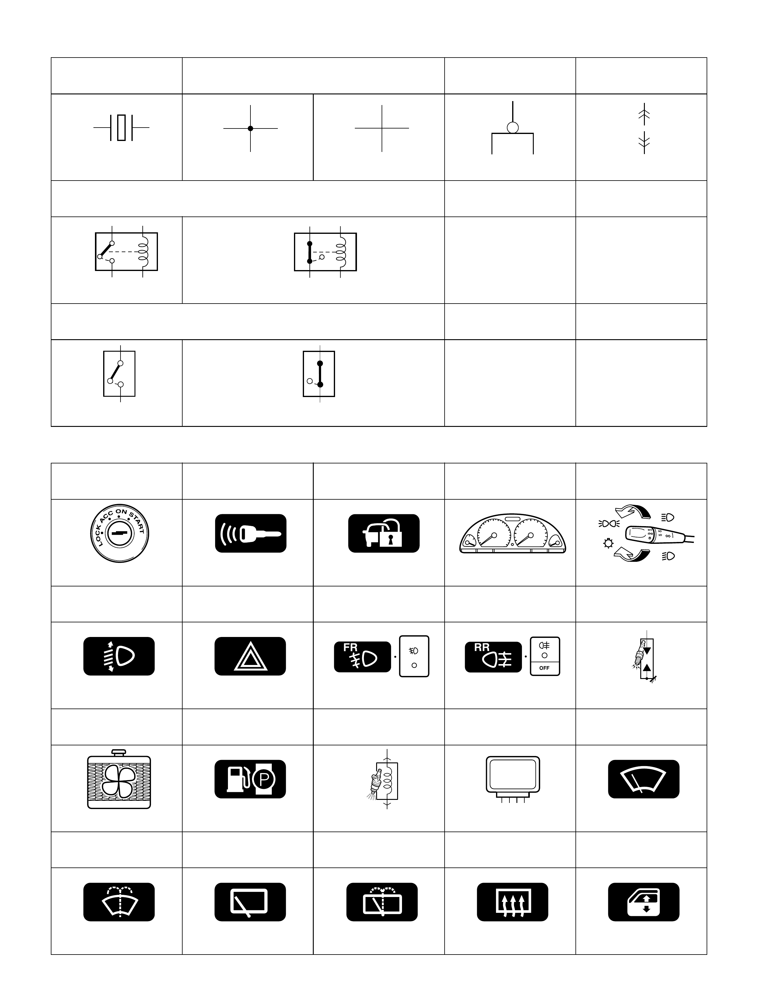
Piezoelectric ele-
ment Harne ss Rin g term ina l Conn ecto r
Connected Not connected
Relay
Normal open Nor m al closed
Switch
Open switch Closed switch
Ignition switch Keyless entry Immobilizer system Combination meter Lighting switch
Headlight leveling Hazard warning light Front fog light Rear fog light Spark plug
Radiator fa n Fuel pump Injector XX control module Windshield wiper
Windshield washer Rear wiper Rear washer Rear defogger Power window
XX
Cont M
99512-70 H 10-G H E.book Page 8 Friday, Sept ember 26, 2003 3:16 PM
Abbreviations
Power door lock Power mirror A/B Pretensioner Passenger side
Driver side Sea t hea ter A/C Power steering
Abb re viati on Full term Abbreviatio n Full term
2WD 2 wheel drive vehicles IND Indicator
4WD 4 wheel driv e vehicles INT Intermittent
A/B Air bag ISC Idle speed control
A/C Air conditioning J/B Junction fuse block
A/T Automatic trans mission J/C Joint connector
ACC Accessory L Left
CKP Crank shaft position LH (D) Left hand (drive vehicle)
CMP Cam shaft position LO Low
COMB Combination MAP Manifo ld absolute pressure
DLC Data link connector M/T Manual transmission
DRL Daytime running light O/D Over drive
ECM Engine control module P/N Power/Normal
ECT En gine coolant te mperature P/S Power steering
EGR Exhaust gas rec irculation PSP Power steering pressure
EVAP Evaporative R Right
HI High RH (D) Right hand (drive vehicle)
IA C Idle air control SDM Sensing and diagnostic module
IAT Intake air temperature ST Starter
ICM Immobilizer control module TCC Torque converter clutch
IF EQPD If equipped TCM Transmission control module
IG Ignition VSS Vehicle speed sensor
IG COIL Ignition coil VSV Vacuum s witching valve
ILL Illumination
99512-70 H 10-G H E.book Page 9 Friday, Sept ember 26, 2003 3:16 PM
Wire / connector color symbols
Symbol Wire / connector Color Symbol Wire / connector Color
BLK Black ORN Orange
BLU Blue RED Red
BRN Brown WHT White
GRN Green YEL Yellow
GRY Gray PNK Pink
LT BLU Light blue PPL Purple
LT GRN Light green NNatural
GRN (Base color)
GRN (Base color)
YEL (Stripe color)
GRN / YEL
99512-70H10-GHE.book Page 10 Friday, September 26, 2003 3:16 PM
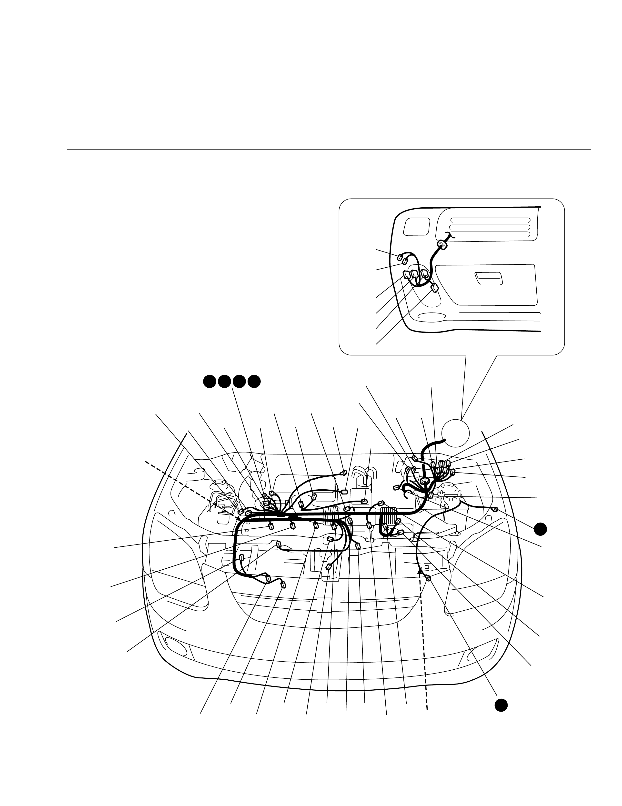
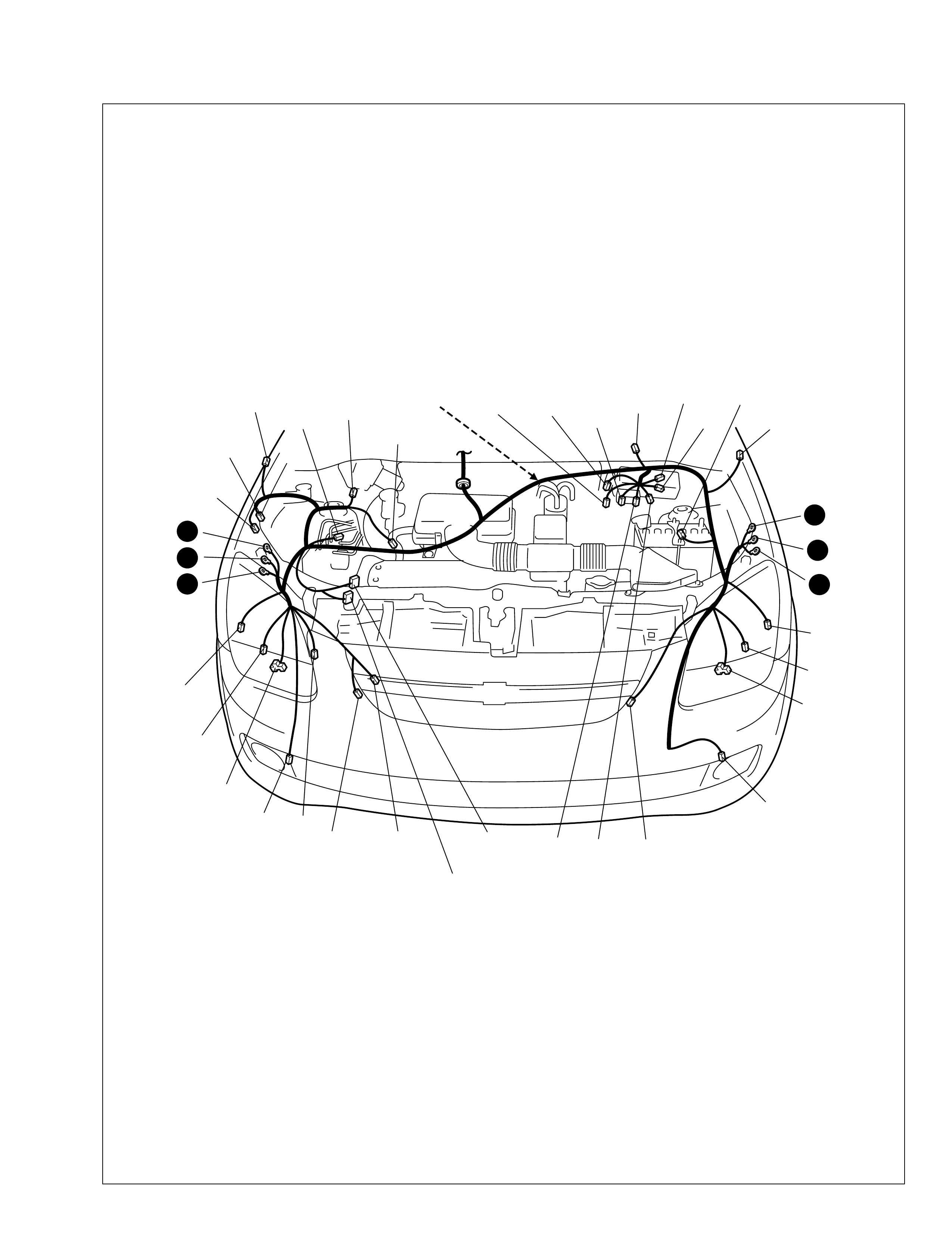
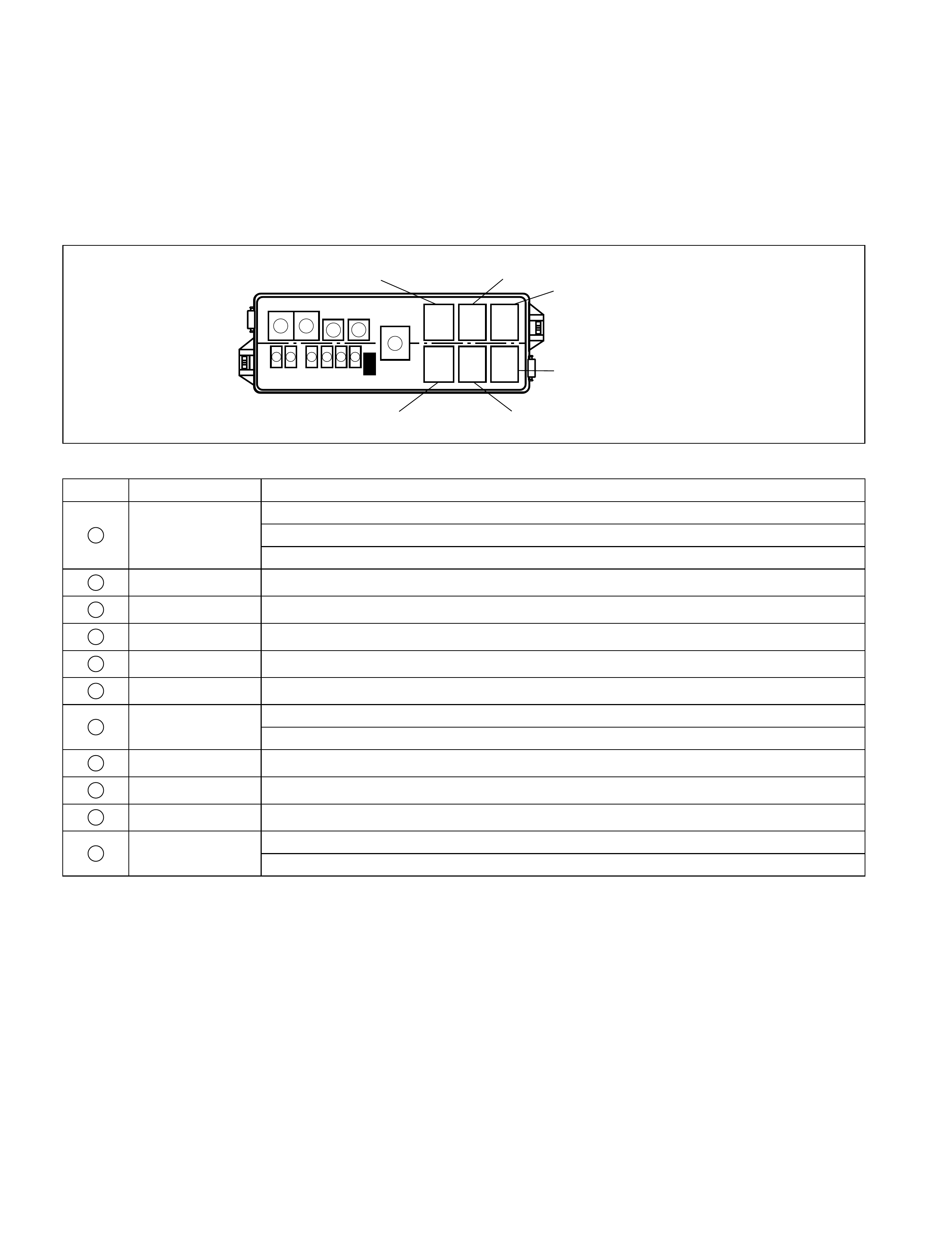
Connector layout diagram
Engine compartment
A: Battery ground cable
C: Engine harness
C01
C02
C03 C04
C08
C05
C06
C10
C09
C14
C15
C11
(TO E10)
C12
C18
C50
C26
C21
C25
C31
C30
C19
C22
C24
C23
C29 C17
C38 C39
C20
C53
C27
C28
C35
C40
C37 C36 C34
C51
C32
3 4 5 6
2
1
C
A
C46
(TO G03)
C43
C42
C41
C54
C45
(TO G04)
99512-70 H 10-G H E.book Page 1 Friday, Sept ember 26, 2003 3:16 PM

No./Color Connective position
Engine harness
C01 Fuse box
C02 Fuse box
C03/N Fuse box
C04/BLK (A/T) A/T relay
C05/BLK A/C compressor relay
C06/BLK Radiator fan relay #1
C08/BLK Fuel pump relay
C09/BLK Condenser fan relay
C10/BLK Main relay
C11/BLK Main harnes s (To E10)
C12/GRY A utomatic transmission
C14/GRY (A/T) 4AT speed sensor
C15/GRY (A/T) Transmission range sensor
C17/BLK IAT sensor
C18/GRY IG COIL #1
C19/GRY IG COIL #2
C20/GRY Vehicle speed sensor
C21/GRY ECT sensor
C22/GRY CMP sensor
C23/GRY Vehicle speed sensor
C23/GR Y Injector #1
C24/GR Y Injector #2
C25/GR Y Injector #3
C26/GR Y Injector #4
C27/BLK MAP sensor
C28/BLK EVAP canister pu rge valve
C29/BLK Throttle position sensor
C30/N Oil pressure s witch
C31/BLK A/C compressor
C32/B L K He at ed oxygen sensor
C34 Generator
C35/GRY IAC valve
C36/BLK Generator
C37/GRY Knock sensor
C38 Starting motor
C39/BLK Starting motor
C40/ GRY CKP Sensor
C41/N ECM
C42/N ECM
C43/GRY TCM
C45/GRY Instrument panel harness (To G04)
C46/N Instrument panel harness (To G03)
C50/GRY EGR valve
C51/BLK (M/T) Back-up light switch
C52/BLU (A/T) Input shaft speed sensor
C53/GRY Dual cut switch
C54/B L K Dia gnosis con nector #1
99512-70 H 10-G H E.book Page 2 Friday, Sept ember 26, 2003 3:16 PM
E: Main harness
E11
E13
E12
E07
E09
E03
E04
E05
E01
E21 E39
E23
E22
E24
E41
<Type 3>
E25
E26
E28 E27
E18
E06
E14
E15
E20
<Type 1&2> E19
<Type 1&2>
E17
E40
<Type 3>
E10
(TO C11) E38
(TO E37)
E16
10
11
12
7
8
9
E
99512-70 H 10-G H E.book Page 3 Friday, Sept ember 26, 2003 3:16 PM

No./Color Connective position
Main harness
E0 1/N Front fog light (L )
E03/N Front position light (L)
E04/GRY Turn signal light (L)
E0 5/BLK Headlight (L)
E06/GRY Radiator fan motor
E07/BLK Radiator fan relay #2
E0 9/N Whe el speed s ensor (F L)
E1 0/BLK Engine harness (To C11)
E11/N Side turn signal light (L)
E12/BRN Main fuse
E13/BRN Main fuse
E1 4/N Main fuse
E1 5/N Main fuse
E1 6/N Front fog light re lay
E17/GRY Brak e fluid level switch
E1 8/N Wheel speed sensor (FR)
E19/BLK ABS control module <Type 1&2>
E20/BLK Horn <Type 1&2>
E2 1/N Front fog light (R)
E22/GRY Turn signal light (R)
E2 3/BLK Headlight (R)
E24/N Front position light (R)
E2 5/BL U Front wash er moto r
E2 6/GRN Rear wa sher motor
E27/N Wiper motor
E28/N Side turn signal light (R)
E38/N Front fog light (option)
E3 9/BLK Condenser fan motor
E4 0/BLK HORN <Type 3>
E41/BLK ABS control module <Type 3>
99512-70 H 10-G H E.book Page 4 Friday, Sept ember 26, 2003 3:16 PM
E: Main harness
E30
E31
E36
(TO G35)
E35
(TO G34)
E34
(TO G33)
E33
(TO L05)
E37
(TO E38)
E
99512-70 H 10-G H E.book Page 5 Friday, Sept ember 26, 2003 3:16 PM

No./Color Connective position
Main harness
E30/N Heater fan motor
E31/N Heater resistor
E33/N Floor harness (To L05)
E34/N Instrument panel harness (To G33)
E35/N Instrument panel harness (To G34)
E36/BLU Instrument panel harness (To G35)
E37/N Front fog light (option)
99512-70 H 10-G H E.book Page 6 Friday, Sept ember 26, 2003 3:16 PM

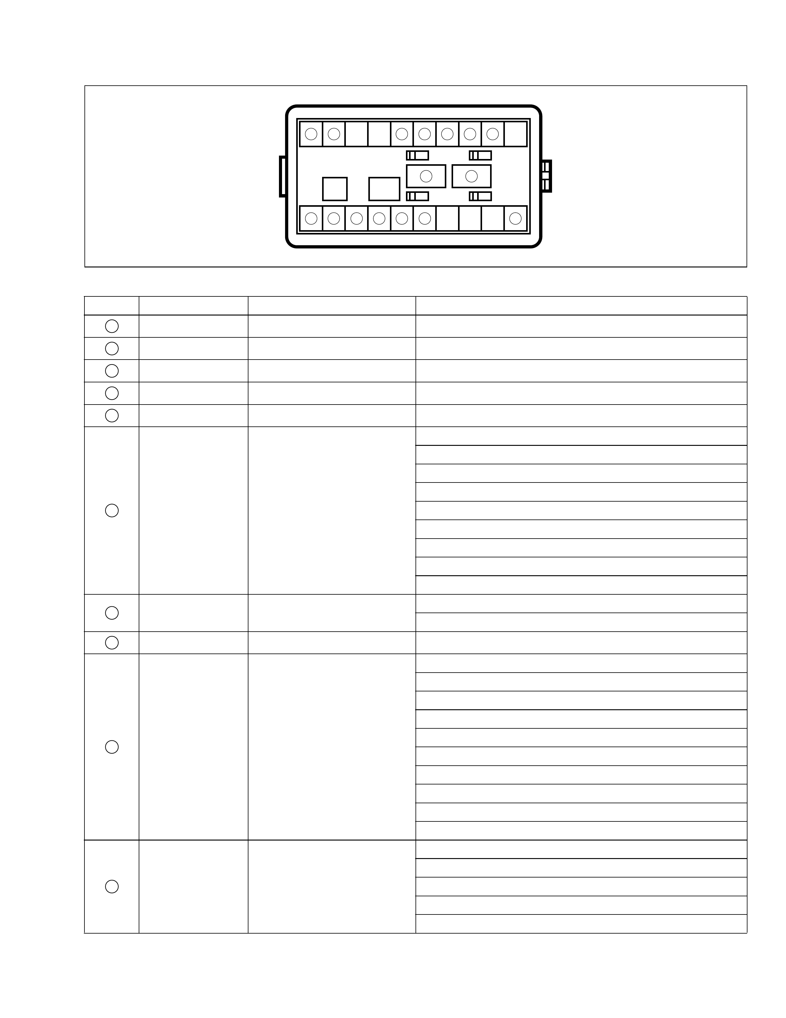
Instrument panel harness
G: Instrument panel harness
G10
(TO J01)
G35
(TO E36)
G37
(TO L07)
G38
(TO L28)
G34
(TO E35)
G33
(TO E34)
G39
(TO L45)
G04
(TO C45)
G01
(TO J07) G03
(TO C46)
G36
G25
G46
G40
G42
G31
G29
G17
G09
<Type 1&2>
G08
G07
G02
G99
G05 G12 G14
G13
G19
G20
G21
G22
G28
G27
G26
G24-2
G16
G44
G32
G23
G06
G98
<Type 3>
G50
G24
G24-1
G49
G15 G51
13
14
16
17 15
G
99512-70 H 10-G H E.book Page 7 Friday, Sept ember 26, 2003 3:16 PM

No./Color Connective position
Instrument panel harness
G01/BLU P ower window sub wire (To J07)
G02/N ECM
G03/N Eng ine harness (To C46)
G04/GRY Engine harness (To C45)
G05/BLK Front speaker (L)
G06/BLK I mm obilizer control module
G07/B LK Dia gn osi s con nec tor #2
G08/N EVAP thermistor #1
G09/N Radio
G10/N Power window main harness (To J01)
G12/GR N Rear defogg er switch
G13/BLK Hazard switch
G14/N Blower fan & A/C switch
G15/N Multi infor mation display
G16/N Cigar lighter
G17/BLK Cigar lighter
G19/B LK Data link connector
G20/BLU Combination meter
G21/N Combination meter
G22/GRY Combination meter
G23/BLK Front speaker (R)
G24/N P/S con tro l modu le
G24-1 /N P/S tor que senso r
G24-2/N P/S motor & clutch
G25/BLK Horn & rear wiper relay
G26/N Combination s witch (dimmer and lighting)
G27/GRY Combination switch (turn signal light)
G28/N Combination switch (wiper)
G29/N Combination switch (rear wiper and washer)
G31/N Main switch (key)
G32/N IG switch
G33/N Main harnes s (To E34)
G34/N Main harnes s (To E35)
G35/BLU Mai n harness (To E36)
G36/N Combination switch (horn)
G37/GRY Floor harness (To L07)
G38/GRY Floor harness (To L28)
G39/YEL Floor harness (To L45)
G40/N Door lock controller
G42/BLK Turn signa l relay
G44/BLK Mirror switch
G46/Y EL Front fog l ight switch
G49/N ILL controller
G50/N EVAP thermistor #2
G51/N Blower fan & A/C switch
G98/BLU RADIO
G99/GRN TCM
99512-70 H 10-G H E.book Page 8 Friday, Sept ember 26, 2003 3:16 PM
Power window main wire
J: Power window main wire, power window sub wire, power window rear wire
K: Dome light harness
J01
(TO G10)
J06
(TO L06)
J12
(TO L09)
J07
(TO G01)
J16
(TO L13)
K01
(TO L01)
J02
J15 J14
J08
J10
J11
J13
J04 J05
J03
(Type 1)
J21
(Type 2) or
J22
(Type 2&3)
J09
(Type 1) or
J19
J18
J17
K03
Power window sub wire
Power window rear wire
K
J
99512-70 H 10-G H E.book Page 9 Friday, Sept ember 26, 2003 3:16 PM

No./Color Connective position
Power window main wire
J01/N Instrument panel harness (To G10)
J02/N Front power window motor (Driver side)
J03/GRN (Type 1) Mirror motor (Driver side)
J04/N Power window main switch
J05/GRY Front door lock motor (Driver side)
J06/N Floor harness (To L06)
J21/N (Type 2&3) Mirror motor (Driver side)
Power window sub wire
J07/N Instrument panel harness (To G01)
J08/N Front power wind ow motor (Passeng er si de )
J09/GRN (Type 1) Mirror motor (Passenger side)
J10/N Front powe r window sub switch (L)
J11/GRY Front door lock motor (Passenger side)
J22/N (Type 2&3) Mirror motor (Passenger side)
Power window rear wire
J12/N Floor harness (To L09)
J13/N Rear power window sub switch (R)
J14/GRY Rear door lock motor (Driver side)
J15/N Rear power window motor (R)
J16/N Floor harness (To L13)
J17/N Rear power window sub switch (L)
J18/GRY Rear door lock motor (Passenger side)
J19/N Rear power window motor (L)
Dome light harness
K01/BLK Floor ha rness (To L01)
K03/N Interior lig ht
99512-70H10-GHE.book Page 10 Friday, September 26, 2003 3:16 PM
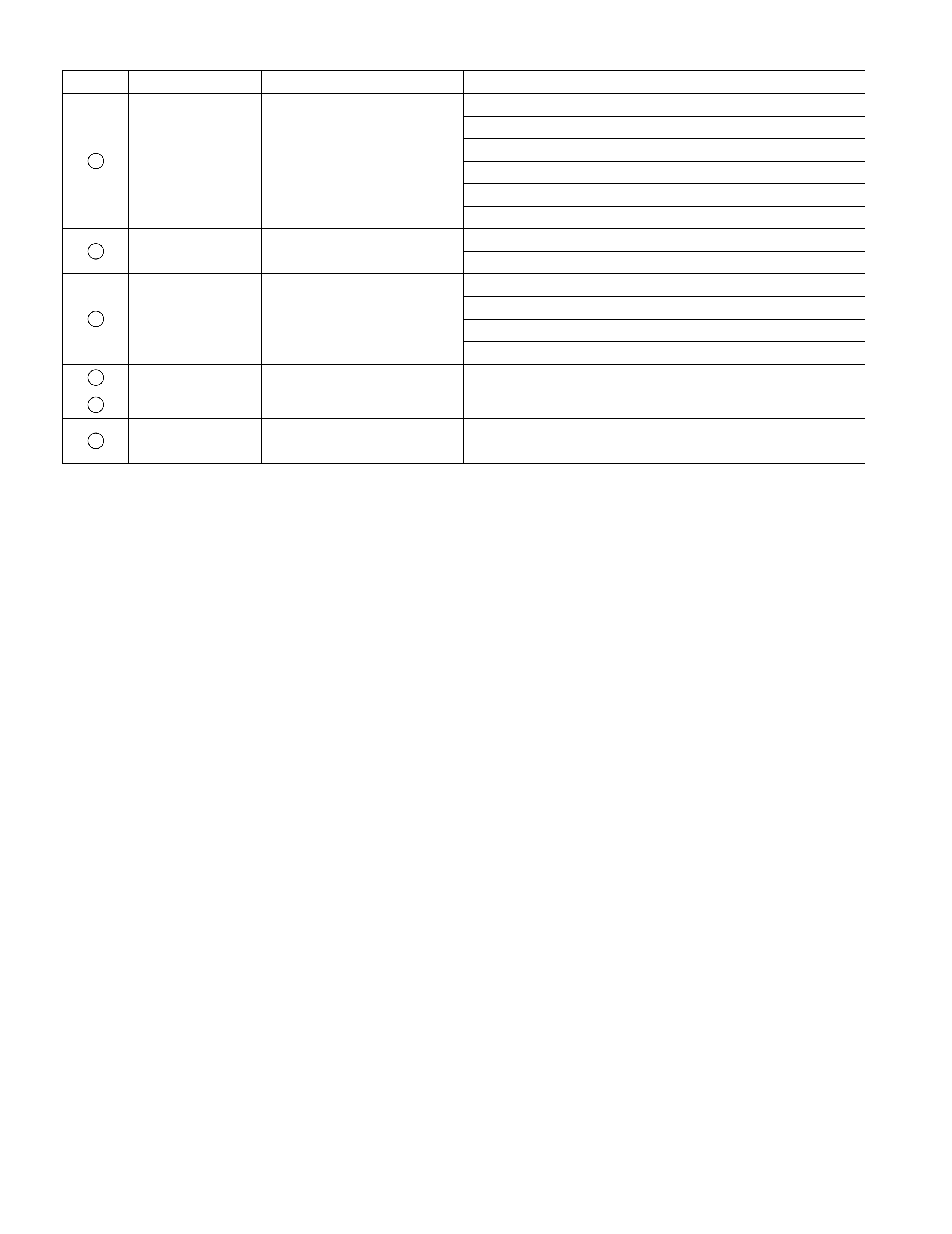
Rear speaker wire
K: Rear speaker wire
L: Floor harness, G sensor wire (4WD),fuel pump harness
L09
(TO J12)
L28
(TO G38)
L07
(TO G37)
L05
(TO E33)
L06
(TO J06)
L23
(TO O01)
L13
(TO J16)
L22
(TO O02)
L01
(TO K01)
L45
(TO G39)
L10 L49
L18
L17
L02
L48
L20
K05L14
L50
L15
L16
K07 L04
L30
L11
L21 L51
L43
L44
L27
L19
L29
K06
L26
L03
L46
L24
K04
Fuel pump harness
G sensor wire (4WD)
20
19
18
23
L32 L08 L47
L12
L31
{
{{
{
K
L
K
99512-70H10-GHE.book Page 11 Friday, September 26, 2003 3:16 PM

No./Color Connective position
Rear speaker wire
K04/N Floor harness (To L24)
K05/N Rea r speaker (R)
K06/N Floor harness (To L26)
K07/N Rea r speaker (L)
Floor harness
L01/BLK Dome light wi re (To K0 1)
L02/BLK Diode #2
L03/N (M/T) Brake light switch
L04/N (A/T) Brak e light switch
L05/N Main harness (To E33)
L06/N Powe r window main wire (To J06)
L07/GRY Instrument panel harness (To G37)
L08/N A/T shift lever
L09/N Power window rear wire (To J12)
L10/ N Front doo r switch (R)
L11/ BL K Parking brake switch
L12/BLU G sensor wi re (To L31)
L13/N Power window rear wire (To J16)
L14/ N Front doo r switch (L)
L15/N Wheel spee d sensor (RL)
L16/N Rear door switch (L)
L17/ N Seat bel t switch
L18/N Wheel s peed sensor (RR)
L19/N Fuel wire (To L29)
L20/N Rear door switch (R)
L21/N Rear combination light (R)
L22/BLU Reare nd door ha rness (To O 02)
L23/N Rearend door harness (To O 01)
L24/N Rear speaker wirer (To K04)
L26/N Rear speaker wirer (To K06)
L27/N Rear combination light (L)
L28/GRY Instrument panel harness (To G38)
L43/N Brake light
L44/N Brake light
L45/YEL Instrument panel harness (To G39)
L46/ YEL Cont act coil
L47/ YEL Passenger infl a tor
L48/ YEL Dia gnosis con nector #3
L49/YEL Pretensioner (Driver side)
L50/YEL Pretensioner (Passenger side)
L51/ YE L Air -ba g c on tro l modu le
L52/YEL Driver inflator
G sensor (4WD)
L31/N Floor harness (To L12)
L32/N G sensor (ABS)
Fuel pum p harness
L29/N Floor harness (To L19)
L30/GRY Fuel pump and gage
99512-70H10-GHE.book Page 12 Friday, September 26, 2003 3:16 PM
Rearend door harness
O: Rearend door harness, high mounted stop light wire, rear defogger wire
O03
O11
O09 O08
O07
O12
O06 O05 O04
O10
O01
(TO L23)
O02
(TO L22)
21
22
High mounted stop light wire
Rear defogger wire
O
{
99512-70H10-GHE.book Page 13 Friday, September 26, 2003 3:16 PM

No./Color Connective position
Rearend door harness
O01/B L U Floor harness (To L23)
O02/N Floor harness (To L22)
O03/N Interior light (rear)
O04/N High mounted stop light wire (To O10)
O05/N Rear defogger (+)
O06/N Rear wiper motor
O07/N License plate light #1
O08/N License plate light #2
O09/N Rearend door switch
High mounted stop light wire
O10/N Rearend door harness (To O04)
O11/N High mounted stop light
Rear defogger wire
O12/N Rear defogger (-)
99512-70H10-GHE.book Page 14 Friday, September 26, 2003 3:16 PM
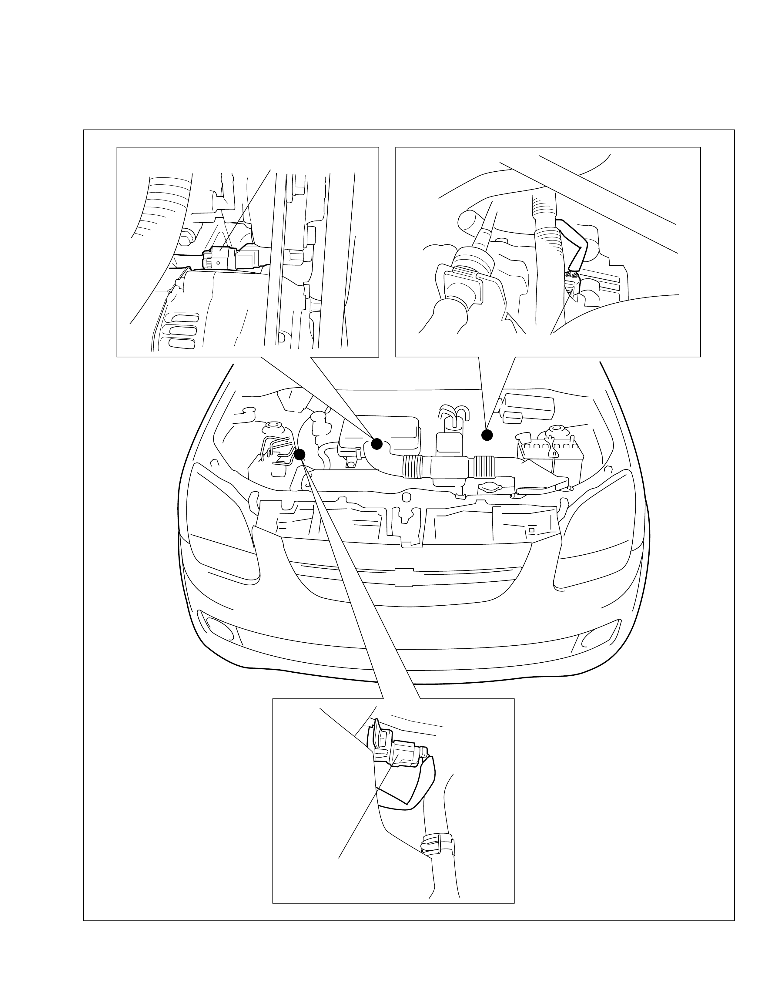
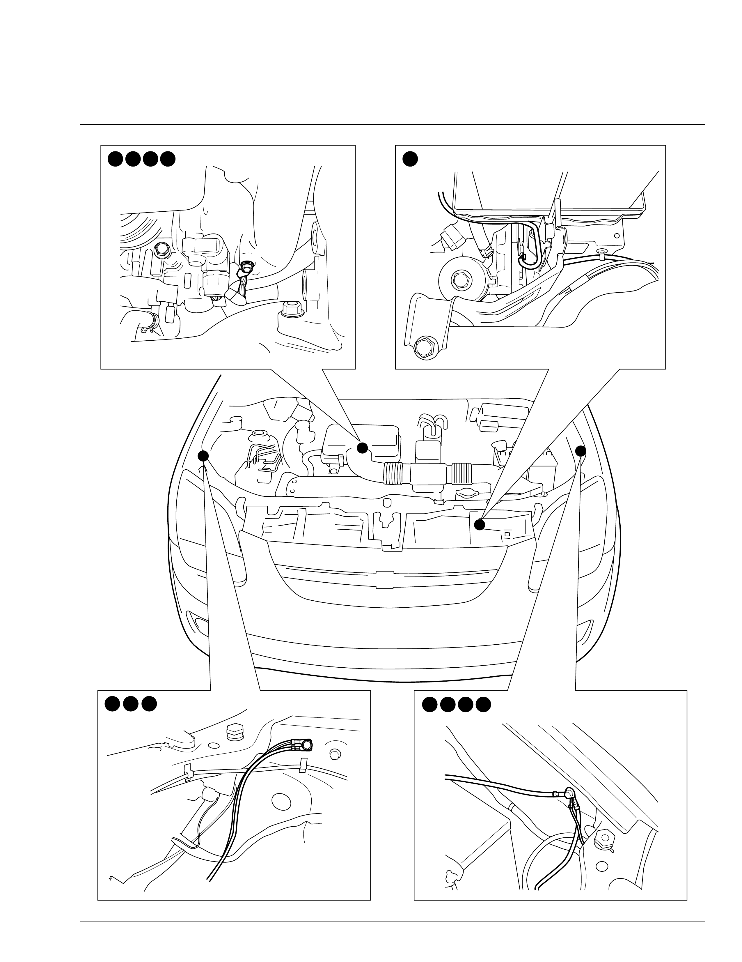
Main electronic control part location
Engine compartment
CKP sensor (C40)
Vehicle speed sensor (C20)
CMP sensor (C22)
99512-70 H 10-G H E.book Page 1 Friday, Sept ember 26, 2003 3:16 PM
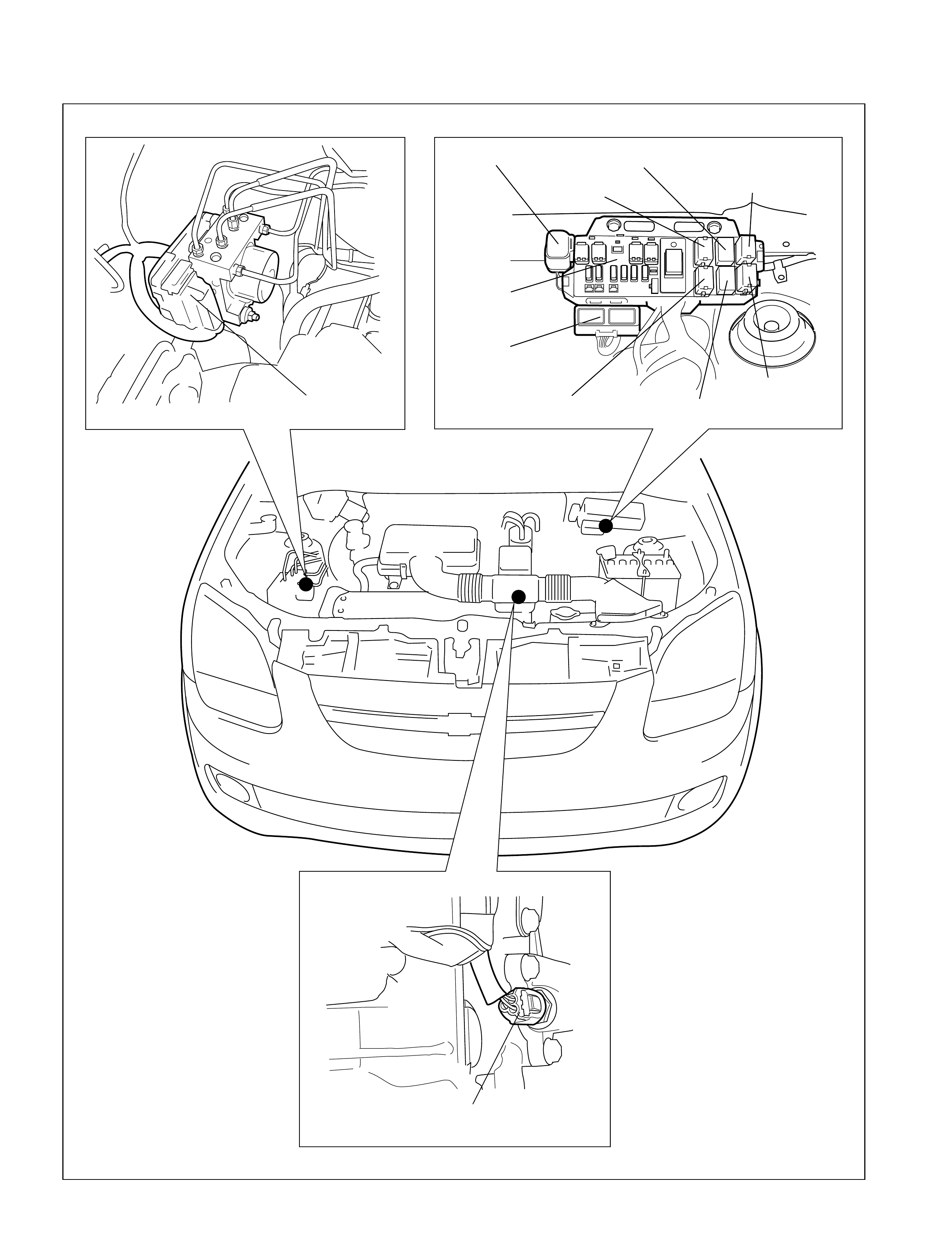
Engine compartment
Radiator fan control
relay #2 (E07)
ABS control module (E19)
Fuse box
Fog light relay (E16)
ECT sensor (C21)
A/T relay (C04) Radiator fan relay #1 (C06)
A/C compressor relay (C05)
Fuel pump relay (C08)
Condensor fan relay (C09)
Main relay (C10)
99512-70 H 10-G H E.book Page 2 Friday, Sept ember 26, 2003 3:16 PM
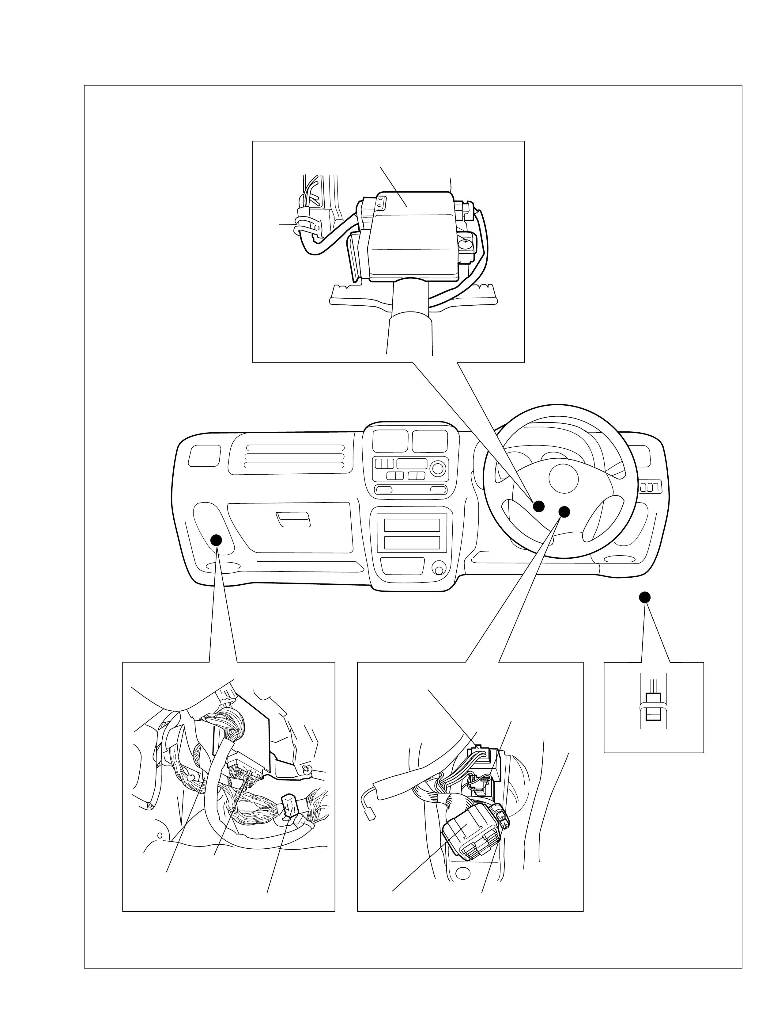
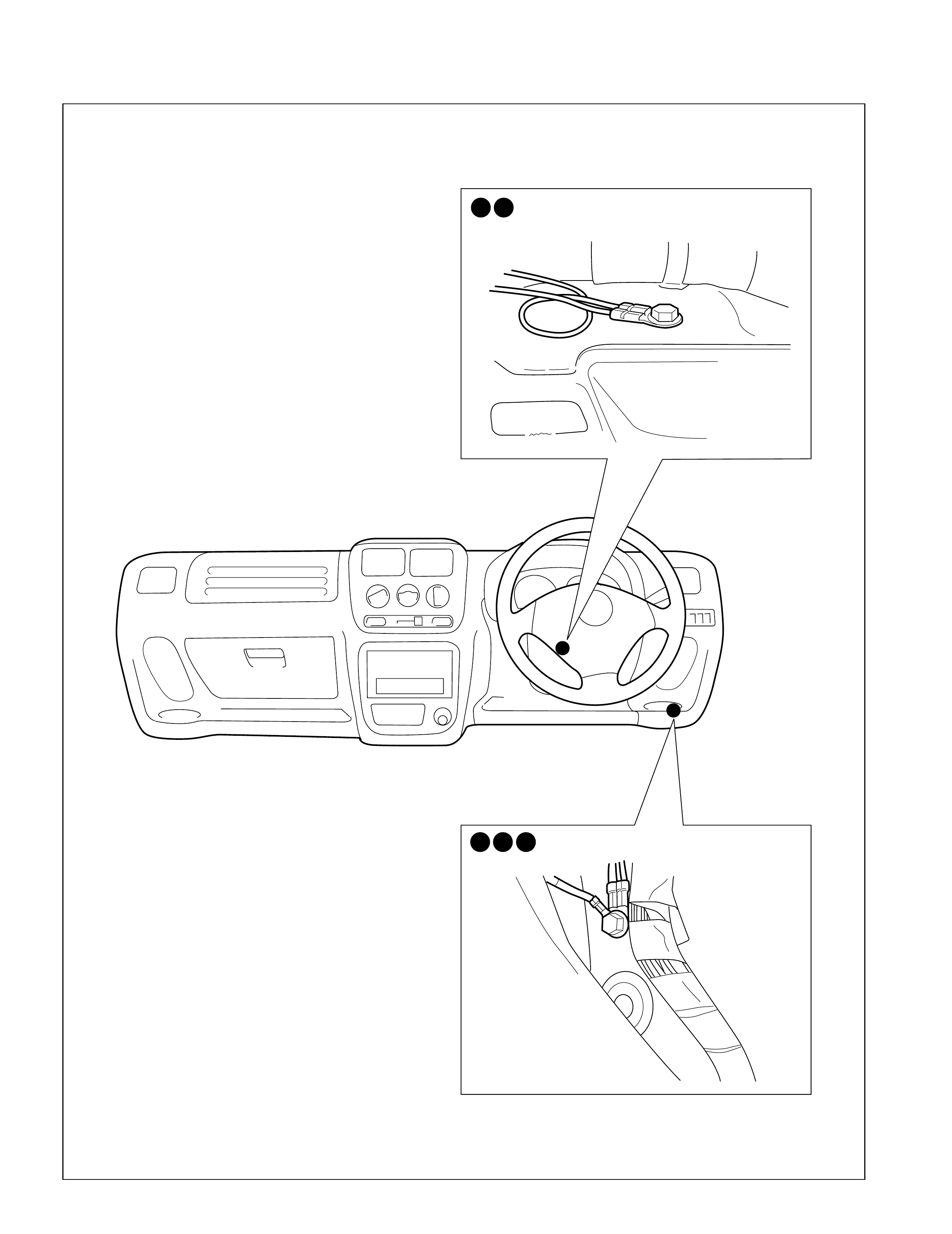
Instrument panel
P/S control module (G24)
TCM (C43,G99)
Fuse box
Door lock controller (G40)
ECM (C41,C42,G02)
Diagnosis connector #1 (C54)
Turn signal relay (G42)
Diode #2 (L02)
Horn & rear wiper relay (G25)
99512-70 H 10-G H E.book Page 3 Friday, Sept ember 26, 2003 3:16 PM
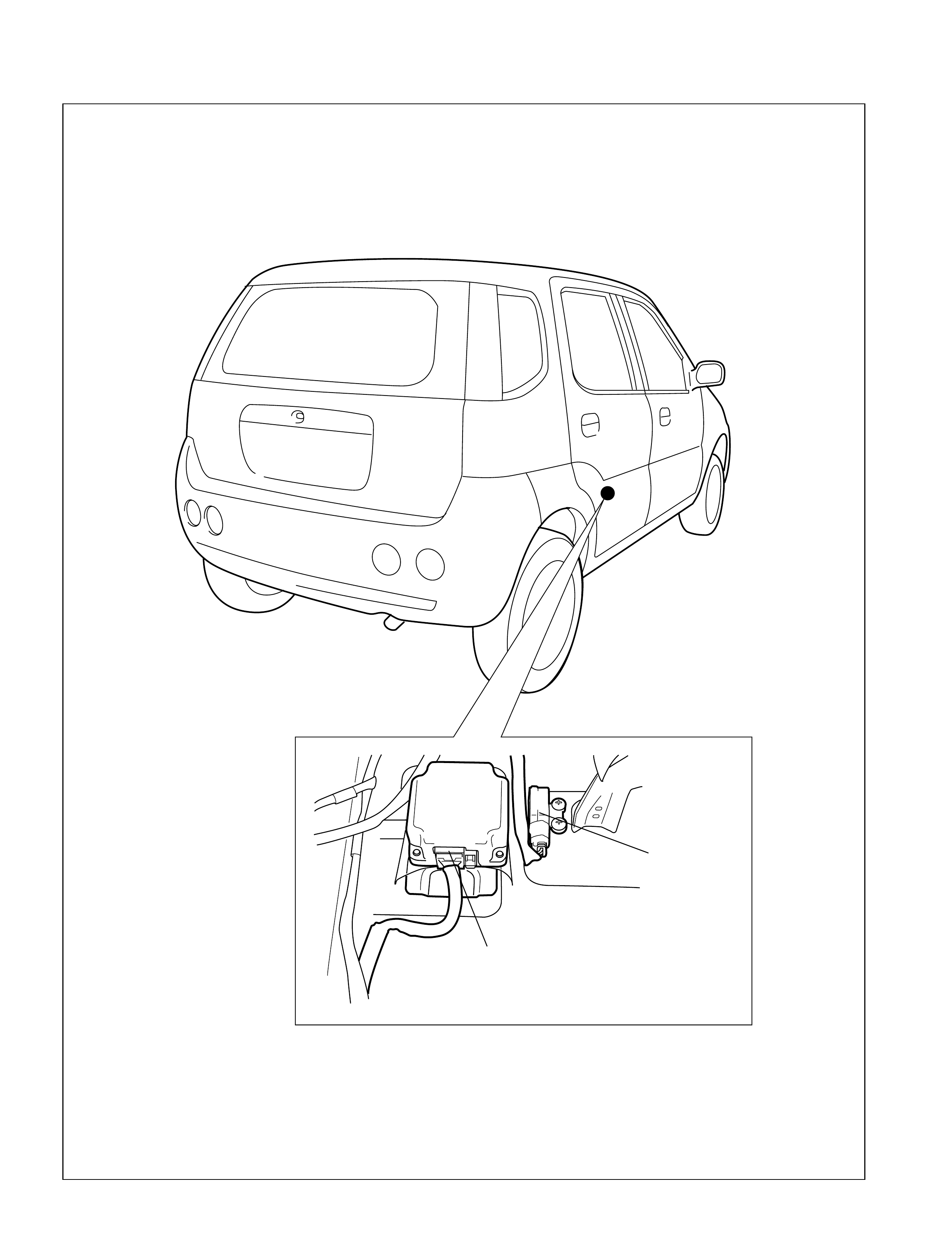
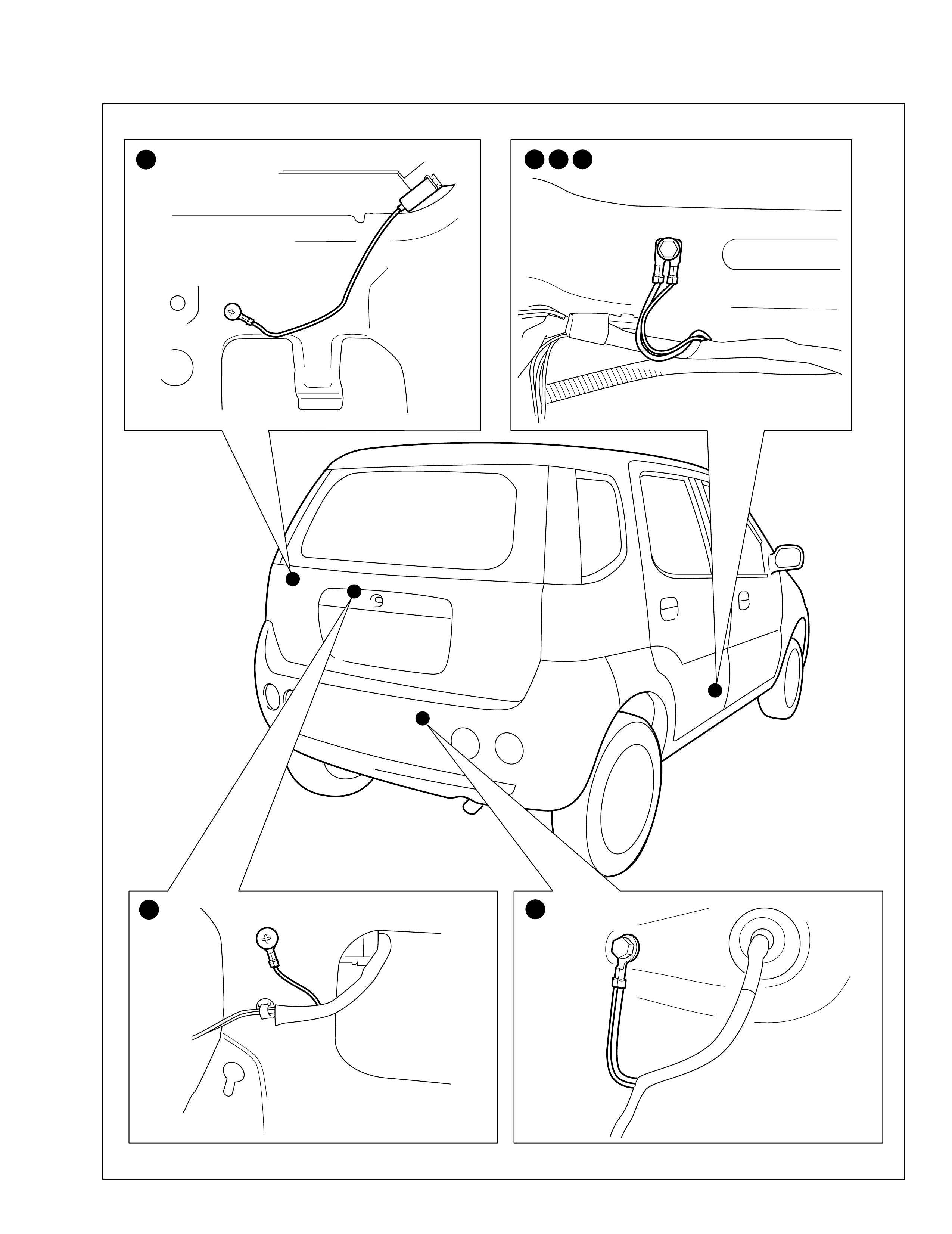
Floor
G sensor (L32)
Air bag control module (L51)
99512-70 H 10-G H E.book Page 4 Friday, Sept ember 26, 2003 3:16 PM
Ground point
Engine compartment
3 4 5 6 1
10 11 12 2 7 8 9
99512-70 H 10-G H E.book Page 1 Friday, Sept ember 26, 2003 3:16 PM
Instrument panel
13 14
15 16 17
99512-70 H 10-G H E.book Page 2 Friday, Sept ember 26, 2003 3:16 PM
Floor
22 18 19 23
21 20
99512-70 H 10-G H E.book Page 3 Friday, Sept ember 26, 2003 3:16 PM
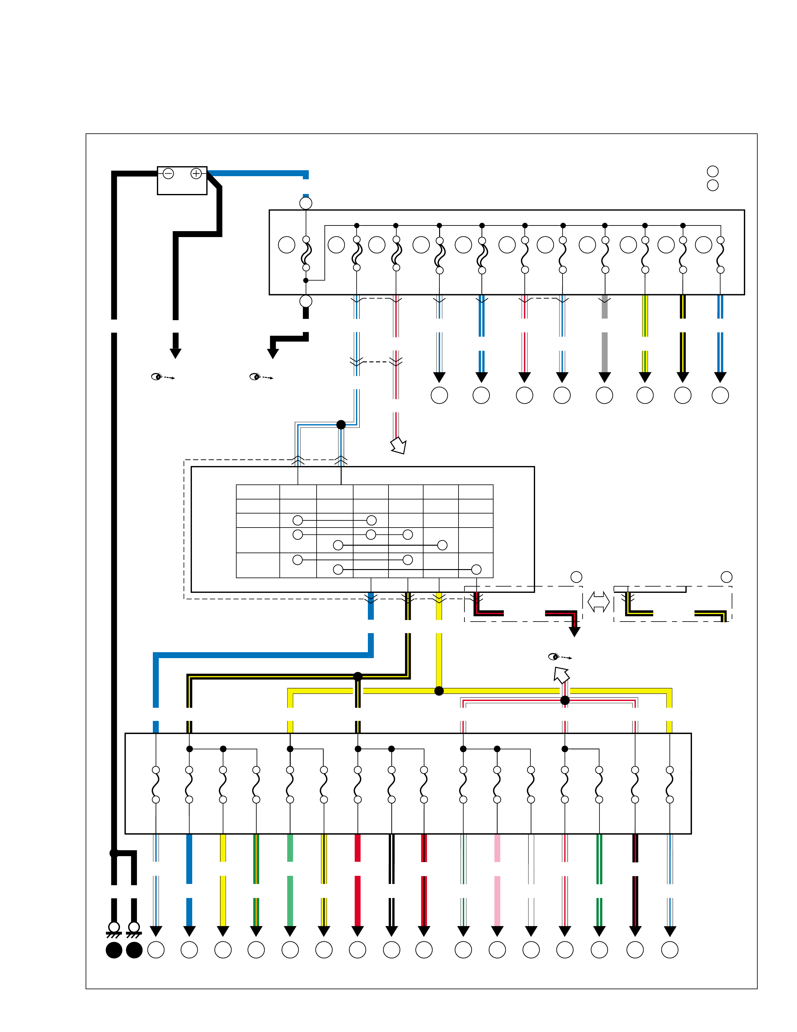
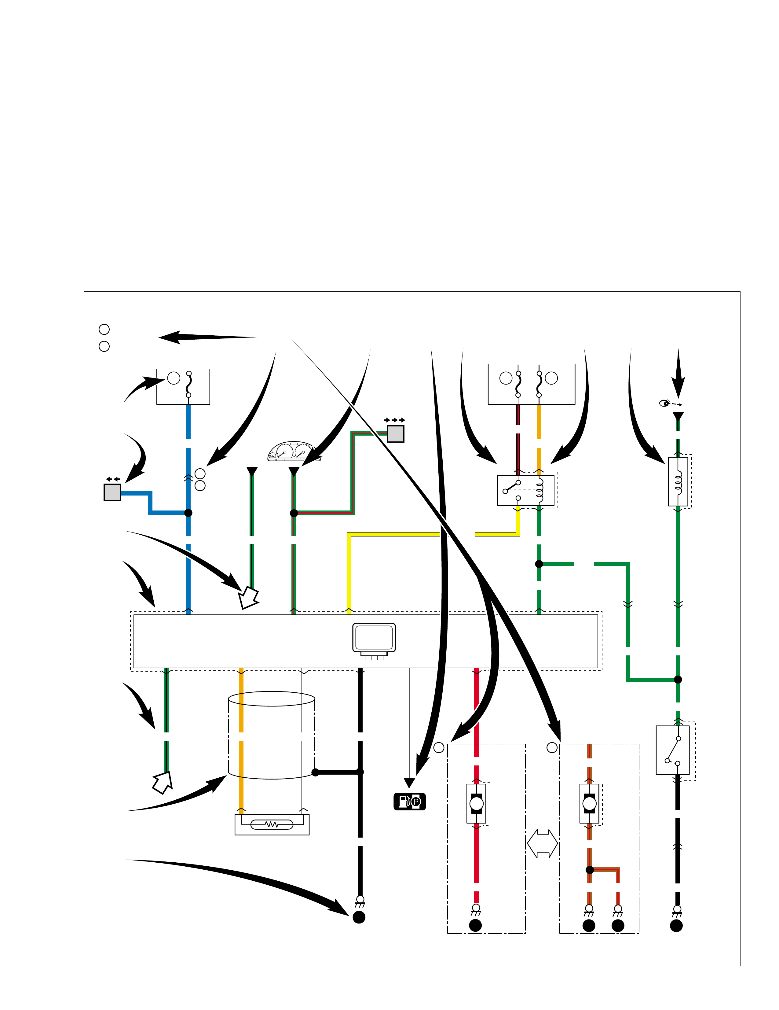
Power supply diagram
Power supply diagram
C01
21
1
1
C02 E15
80A 60A 60A
413
6
2
IG switch
Lock B1 B2 ACC IG1 IG2 ST
ACC
ON
Start
G32
BLK
BLK
BLK
WHT/RED
WHT/BLU
BLK/YEL
BLU
BLK BLK
BLK/YEL WHT/RED
BLU
WHT/RED
3
E34
G33 4
5
3
Fuse box
Main fuse box
BLU
11 12 13 14 16
18
26 19 171521 2223 2524
15A 10A 20A 15A 15A10A10A 15A 10A 30A 30A25A15A
BLU
YEL
GRN/ORN
LT GRN
YEL/BLK WHT/GRN
15A
BLK/WHT
20
10A
RED/BLK PNK
WHT GRN/WHT
WHT/RED
WHT/BLU BLK/RED
WHT/BLU
15A
RED
WHT/RED
WHT/BLU
1
E13E14 E12 21
15A
15A 20A
1
15A
WHT/BLU
GRY
15A
BLK/YEL
WHT/BLU WHT/RED
C03 1
30A
BLU/WHT YEL/GRN
50A
12346 8 10
975
46 8 10
20A
BLU/WHT
11
11
975
2
1
Starting motor Generator
Starting motor
YEL YEL
YEL
AM/T
A/T
B
B
WHT/RED
BLK/RED
BLK/YEL
"A-1" "A-2"
"A-2"
1
1
A
BLK/YEL
99512-70 H 10-G H E.book Page 1 Friday, Sept ember 26, 2003 3:16 PM
Fuses and the protected parts
The chart below describes what parts each fuse protects.
Fuses in main fuse box
USE the designated fuses only
Relay
1Relay
2
Relay
5Relay
6
Relay
3Relay
4
Fuel pump relay (C08) Condensor fan relay (C09)
2 3 1
45
678 9
10 11
A/C compressor relay (C05)A/T relay (C04)
Radiator fan relay #1 (C06)
Main relay (C10)
No. Amperage Protected circuit
80A Battery
Generator
All electric circuit
60A IG switch
60A Circuit fuse box
50A ABS contro l modu le
30A Radiator fan relay #1
15A Head light (R)
15A Combination meter
Head light (L)
20A Front fog light relay
15A A/T re lay
15A Main relay
20A A/C compressor rela y
Condenser fan rela y
1
2
3
4
5
6
7
8
9
10
11
99512-70 H 10-G H E.book Page 2 Friday, Sept ember 26, 2003 3:16 PM
Fuse in circuit fuse box
USE The designated
fuse only
23
25
24
22 262120
18
11 12 17
19
16
151413
No. Amperage Description on the cover Protected circuit
25A HEATER
Heater fan motor
15A REAR DEFG
Rear defogger switch
20A DOOR LOCK
Door lock controller
10A STOP
Brake light switch
10A TAIL
Combination switch (Lighting switch)
15A RADIO.DOME
ECM
Data link connector
Combination meter
Dome light
Dome light (Rear)
Radio
Main switch (Key switch)
Multi information display
TCM
15A HORN
Horn relay
Combination switch
15A AIRBAG
Air bag control module
15A IG
Generator
Immobilizer control module
IG COIL #1
IG COIL #2
A/T relay
Fuel pump relay
Heated oxygen sensor
ECM
Warning buzzer controller
P/S controlle r
10A BACK
Transmission range sensor
Hazard switch
Combination switch
Back-up light switch
Blower fan and A/C motor
11
12
13
14
15
16
17
18
19
20
99512-70 H 10-G H E.book Page 3 Friday, Sept ember 26, 2003 3:16 PM
15A WIPER.WASHER
Combination switch
Wipe r mo tor
Rear wiper & washer switch
Rear wiper relay
Rear wiper motor
Multi information display
10A ABS ABS control module
G sensor (ABS)
15A CIGAR
Mirror switch
Radio
Cigar lighter
Multi information display
30A P/S P/S controller
30A POWER WINDOW Power window switch
10A METER Comb i nat ion meter
Turn signal relay
No. Amperage Description on the cover Protected circuit
21
22
23
24
25
26
99512-70 H 10-G H E.book Page 4 Friday, Sept ember 26, 2003 3:16 PM
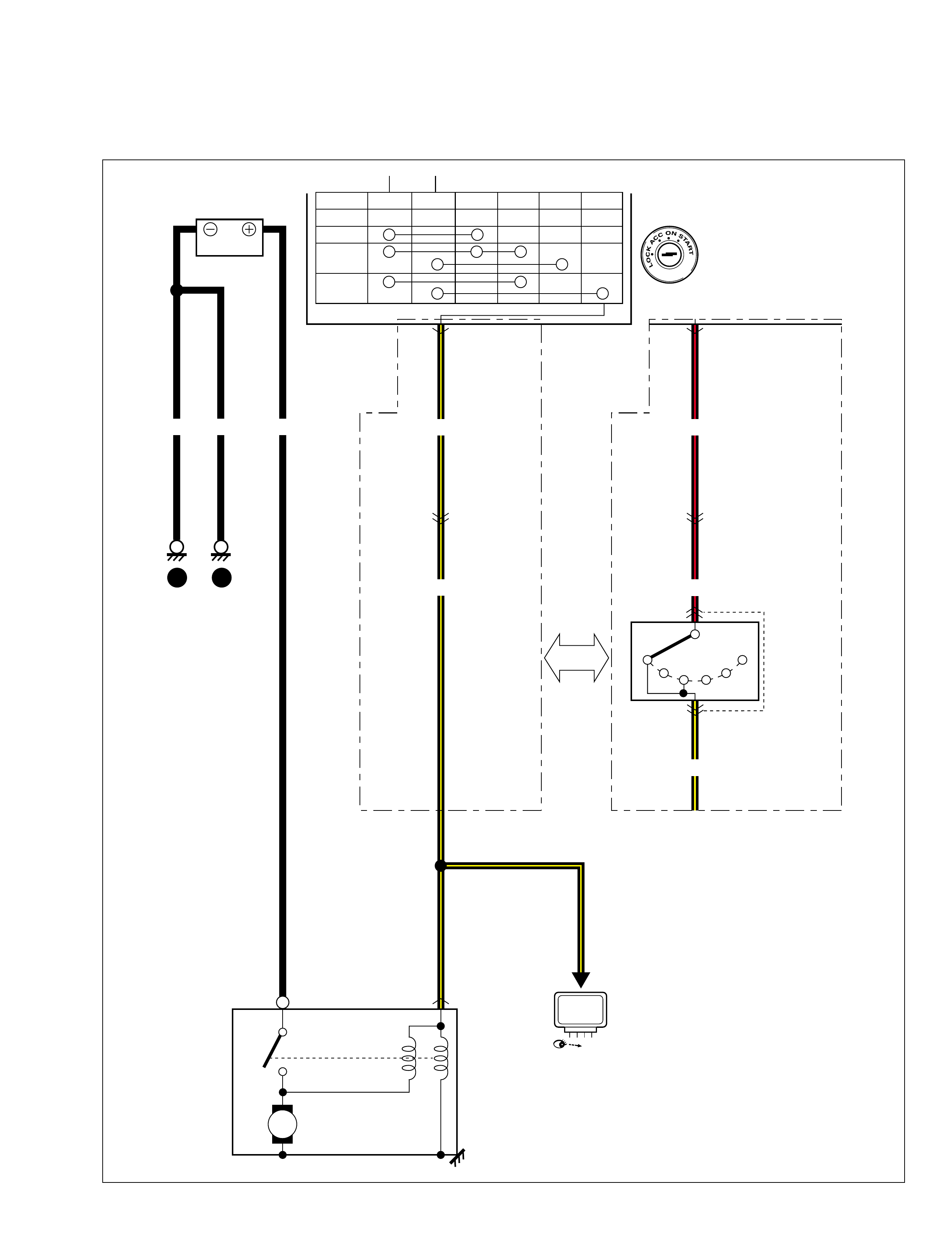
System circuit diagram
A-1 Cranking system
M/T A/T
PRND2L
G32
1
1
C38
3
C39
G32 3
12
G03
C46 12
G03
C46
M
BLK/YEL
C15 9
6
BLK/YEL
BLK BLKBLK BLK/RED
BLK/RED
BLK/YEL
LOCK B1 B2 ACC IG1 IG2 ST
ACC
ON
START
Starting
motor
Transmission
range sensor
12
"A-6"
ECM
99512-70 H 10-G H E.book Page 1 Friday, Sept ember 26, 2003 3:16 PM
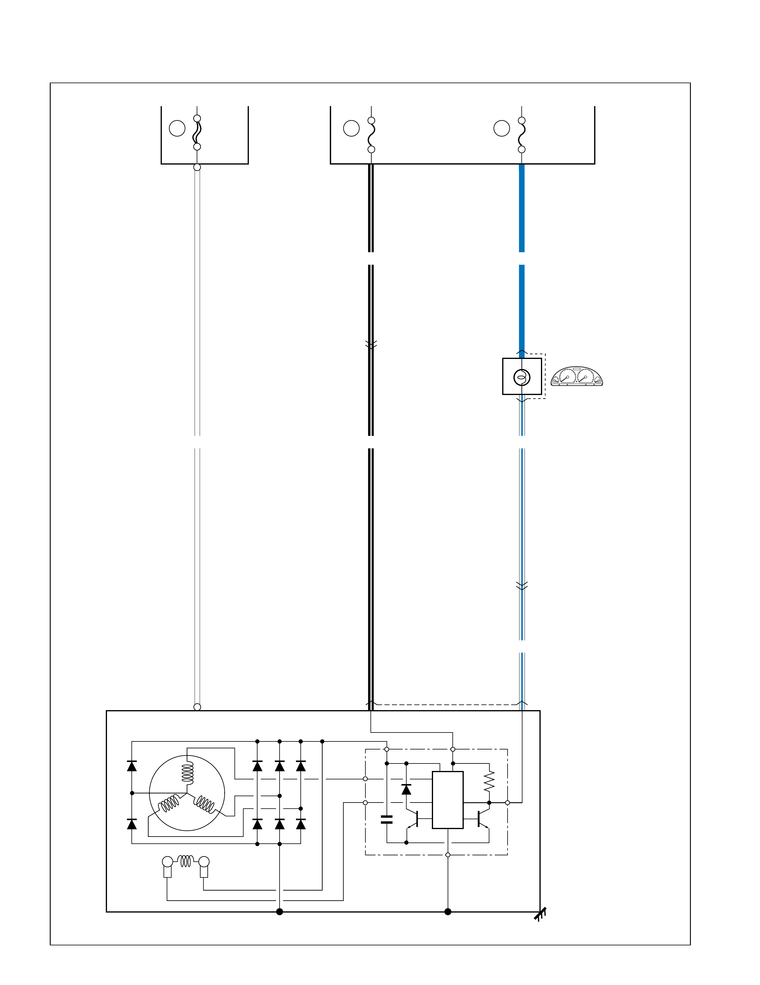
A-2 Charging system
C34 1
C02 1
G03
C46
G03
C46 13
C36 12
8
1
80A
BLK/WHT
WHT/BLU
WHT/BLU
BLUBLK/WHT
WHT
10
G22
CHARGE
5
15A
19
Generator
P
F
0.5 F
E
IC
REGULATOR
BL
IG
Fuse box
Main fuse IG 10A
26 METER
99512-70 H 10-G H E.book Page 2 Friday, Sept ember 26, 2003 3:16 PM
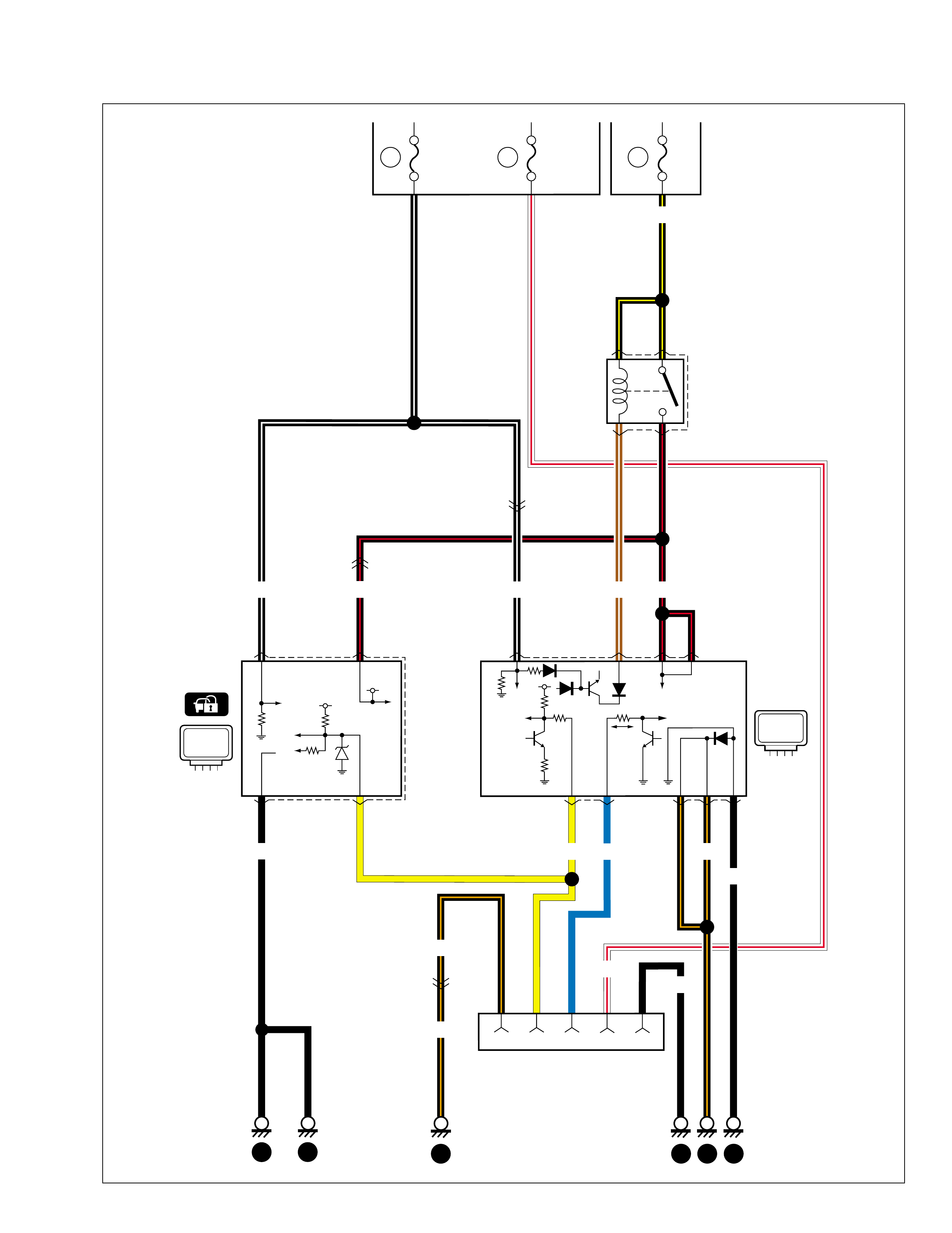
A-3 Immobilizer control system
C41 11 10 6
15A
15A IG
C10 24
13
BRN/WHT BLK/RED
BLK/YEL
19 10
15A
RADIO.
DOME
16
Fuse box Main fuse
Main relay
Data link connector
514
4
G19 16
59
YEL
G06
BLK/WHT BLK/RED
BLK/ORN
BLK/ORN
BLK
14
G03
C46
10
C46
G03
13
G03
C46
13 15
BLK
43
21
7
BLU
117
BLK/ORN
1
4
BLK
2
3
3
C42G02
5
WHT/RED
BLK/WHT
ICM ECM
99512-70 H 10-G H E.book Page 3 Friday, Sept ember 26, 2003 3:16 PM
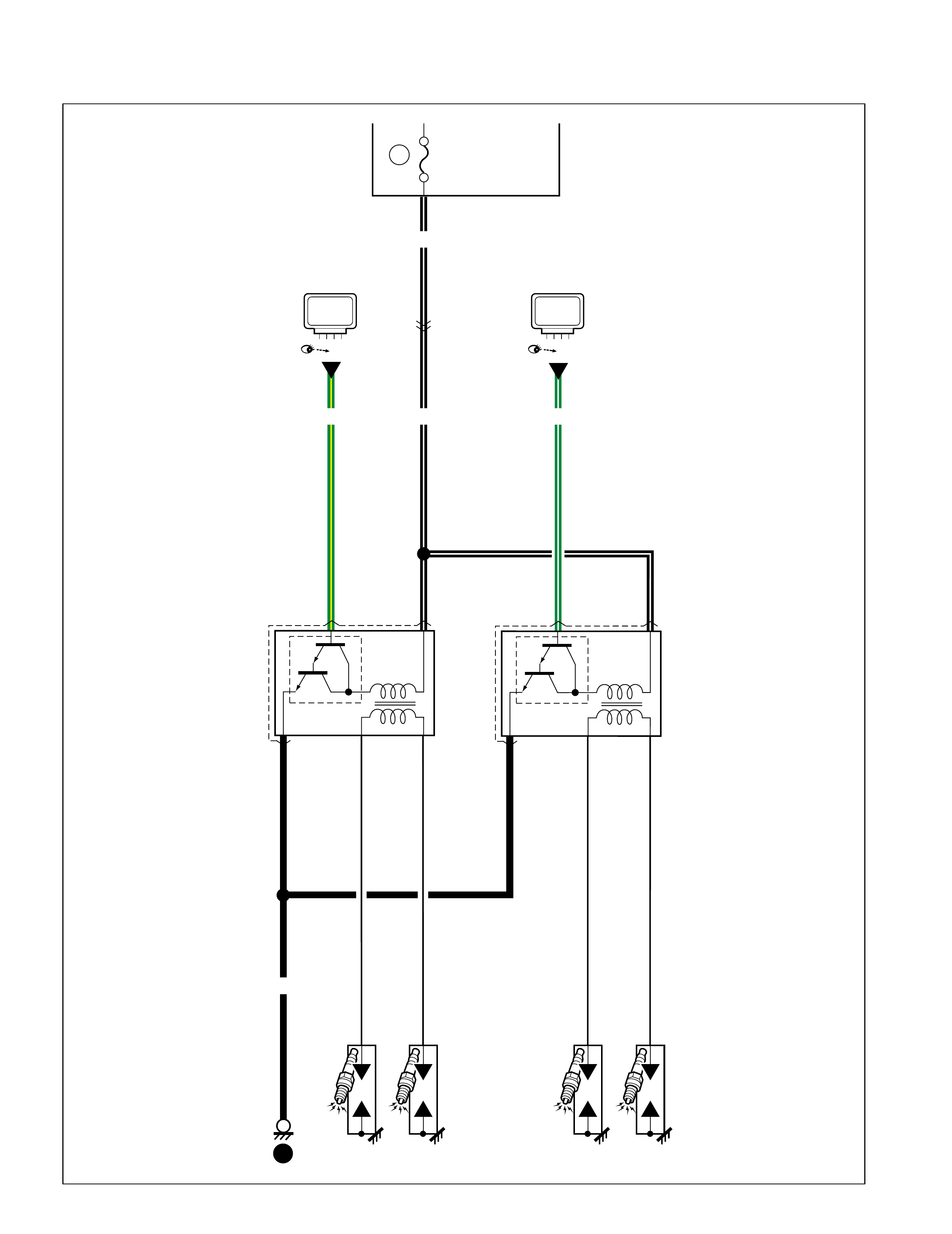
A-4 Ignition system
19
15A IG Fuse box
IG COIL #1 IG COIL #2
13
G03
C46
2
C18 13
2
C19 13
BLK/WHT
BLK/WHT
BLK
GRN/YEL GRN/WHT
3
"A-6" "A-6"
ECM ECM
99512-70 H 10-G H E.book Page 4 Friday, Sept ember 26, 2003 3:16 PM

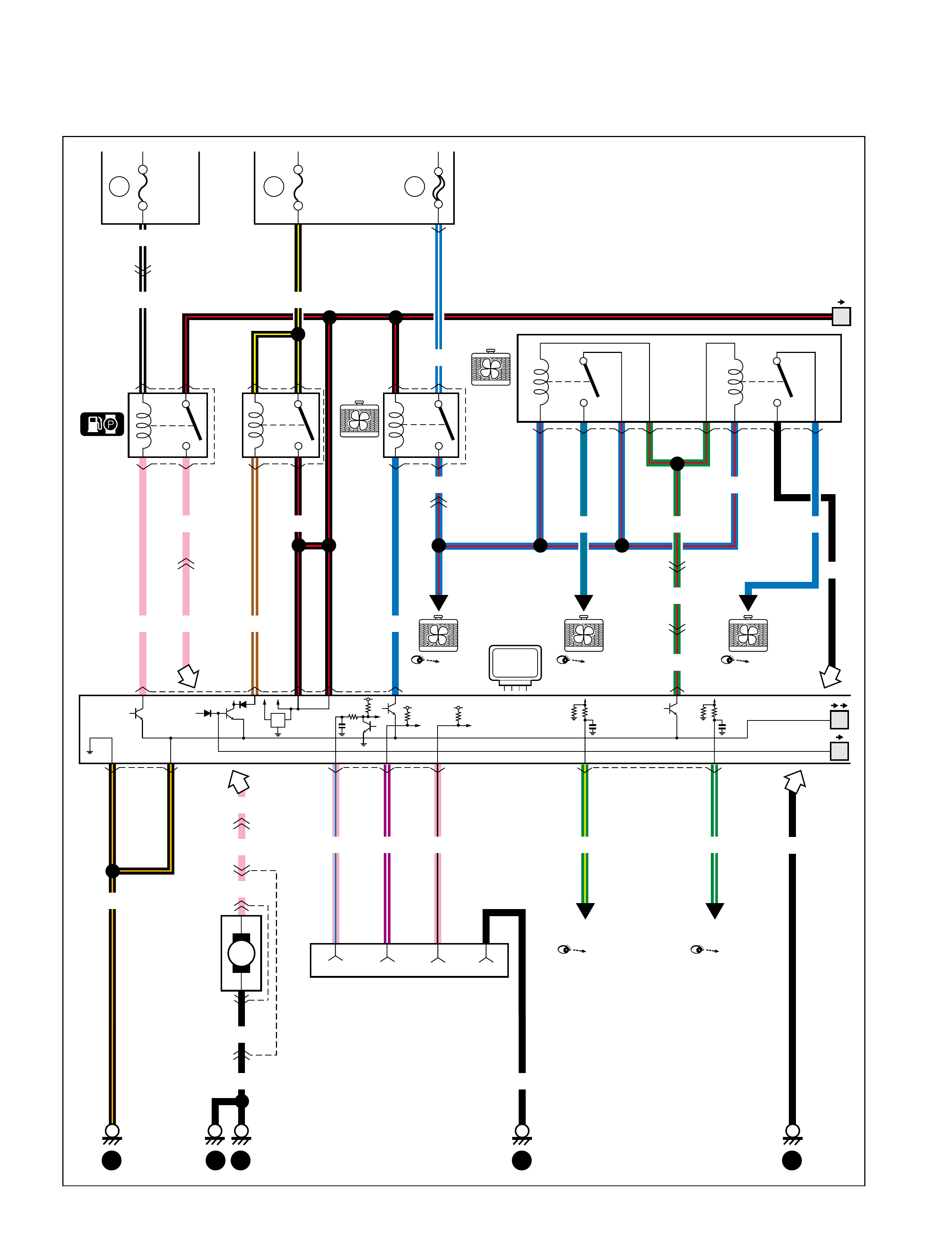
A-5 Cooling system
5Main fuse
Main relay
E06
M
213
4
30A
2
C11
E10 13
E35
G34
2
G03
C46
9
BLK/RED BLU/WHT
C06 23
C03 1
14
E07 154 3 8 6 10 9
GRN/RED
GRN/RED
BLU/RED
BLU/RED
BLU BLU/GRN BLK BLU
"A-6"
"A-6"
Relay #1
Relay #2
GRN/RED
ECM
"A-6"
ECM
99512-70 H 10-G H E.book Page 5 Friday, Sept ember 26, 2003 3:16 PM
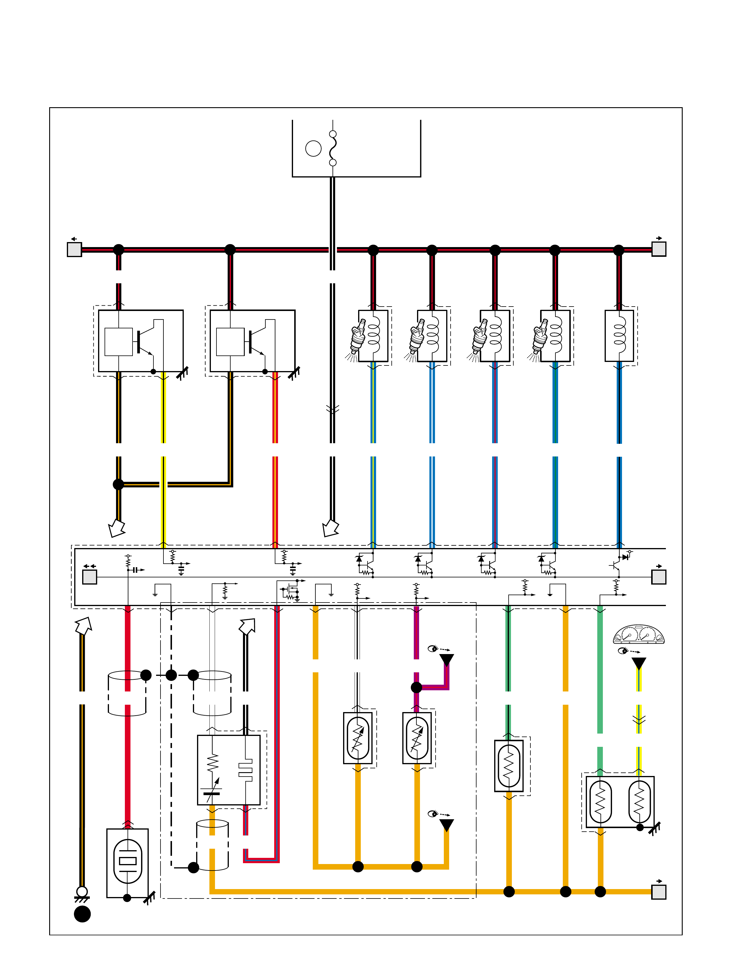
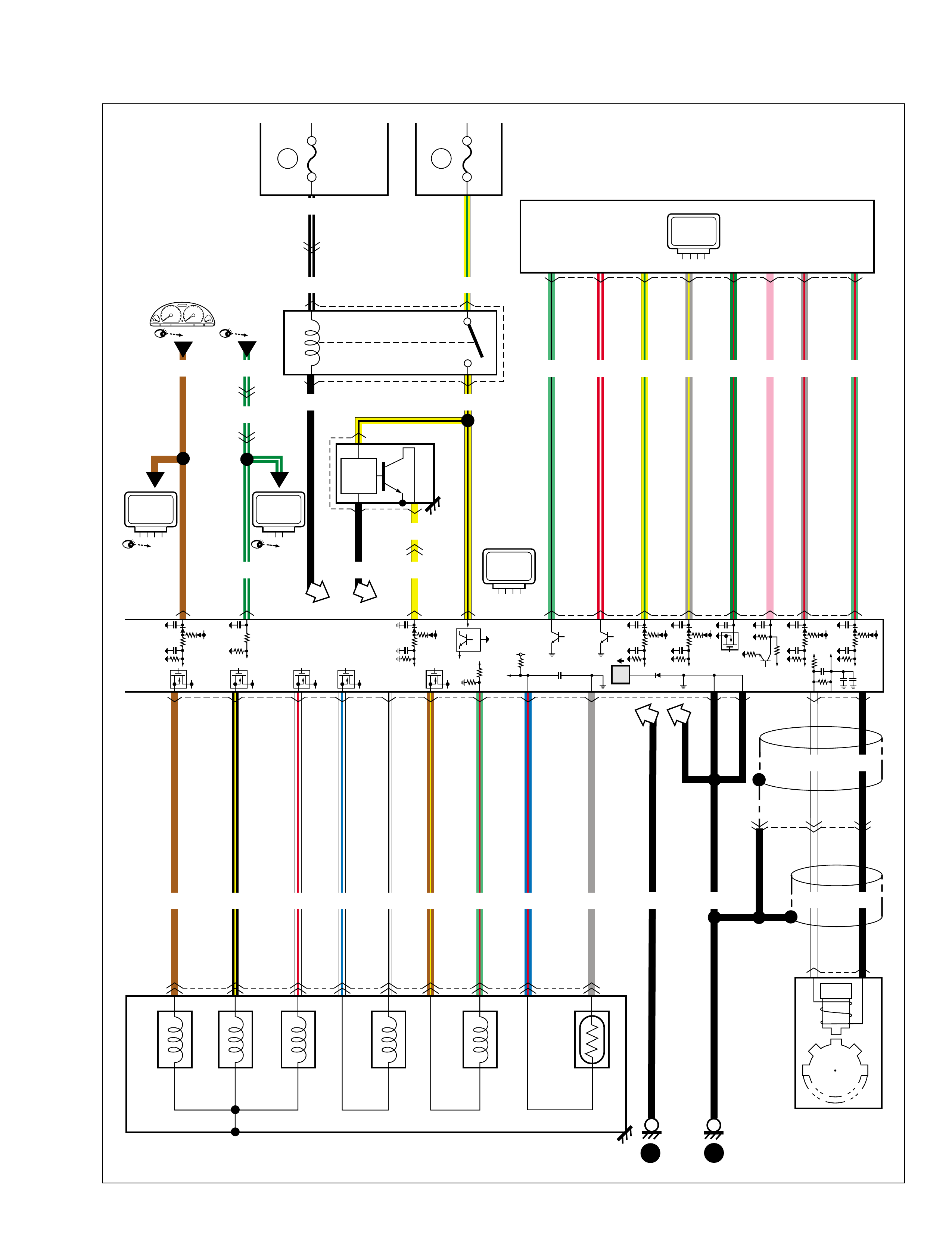
A-6 Engine & control system
(1/4)
C42 C41 C42
C41 C41
1 3
19 10 6 5 18 9
15A15A IG
C08 23
14
C03
23
1
14
E07 154 910683
C10 C06
24
13
8 14 15 19
C54 6254
PNK
BLK/WHT
BLK/WHT
BLU/RED
BLUPNK
PNK
PNK/BLU PPL/WHT PNK/BLK GRN/WHT
3
C46
G03 13
E35
G34
2
G03
C46
2
C11
E10
BLK
BLK
PNK
PNK
PNK
BLK/ORN
15
G38
L28
L30
P
3
4
4
3
L19
L29
13
G03
C46
20
GRN/YEL
BRN/WHT
BLK/RED
BLK/YEL
30A
BLK
2
19 10 5
4 3 918 20
Fuse box Main fuse
BLU/WHT
BLU/RED
BLU/GRN GRN/RED
GRN/RED
GRN/RED
Main
relay
Ignition coil #1 Ignition coil #2
BLK
BLK
5
4
Fuel pump
and gauge
Diagnosis connector #1
Relay Relay #1
3
3
1
1
"A-4" "A-4"
"A-5"
Relay
#2
"A-5" "A-5"
BLU
ECM
99512-70 H 10-G H E.book Page 6 Friday, Sept ember 26, 2003 3:16 PM
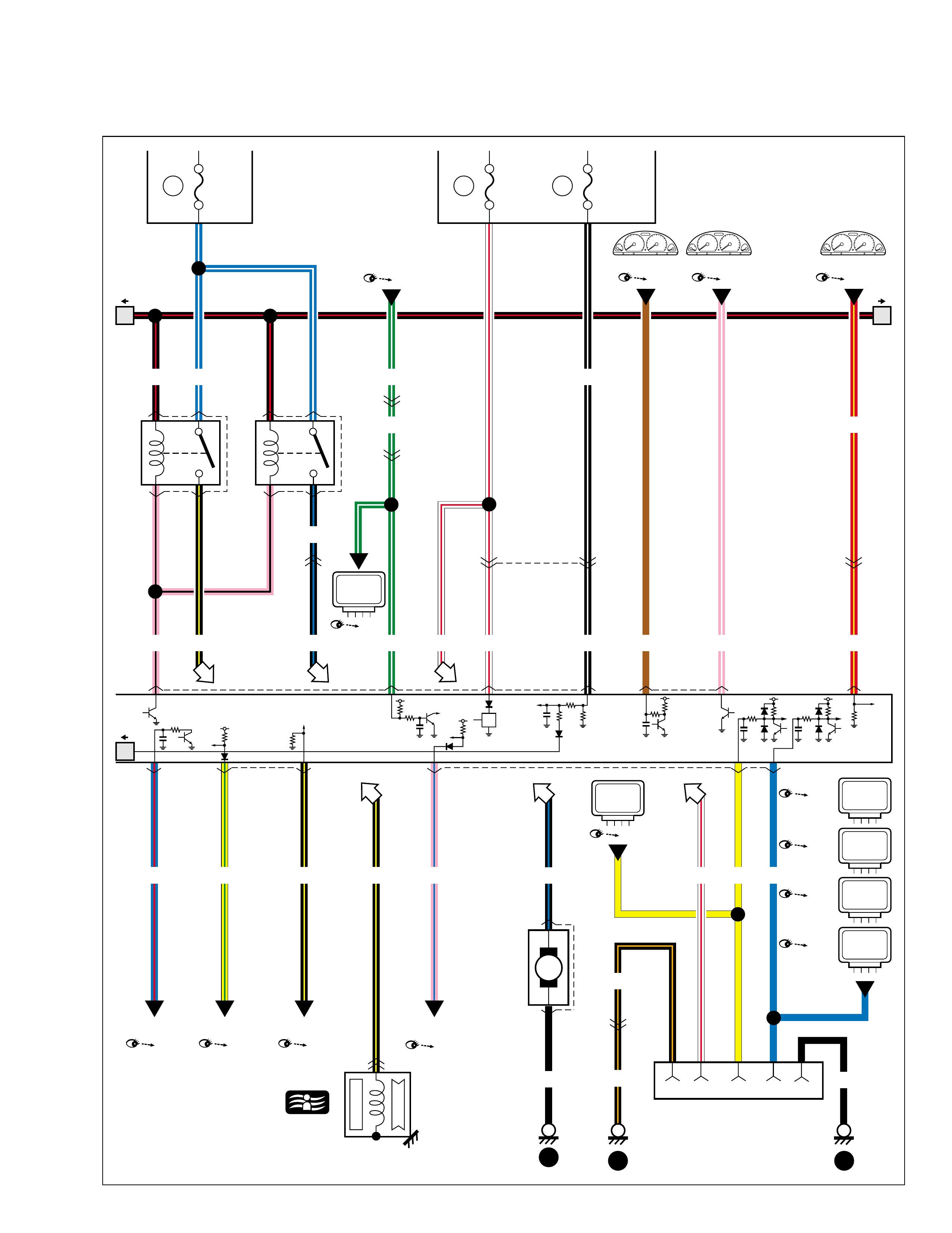
(2/4)
1916
5 14
Fuse box
G02
C42 27 13 117
716 4
G19
1
C31
BLU/RED
C41 16
YEL/GRN PNK/BLUBLK/YEL
5
BLU
9
BLK/ORN
BLK/ORN BLK
4
11
7
15A 15A IG
RADIO.
DOME
11 Main fuse
20A
17916
7
L07
G37
11
G03
C46
1
G03
C46
9
G03
C46
1
C11
E10 13
14
G03
C46
211
C41 G02 C41
Compressor
(Tacho)
Brake light swicth
Dual cut switchGenerator Blower fan & A/C
switch
Data link connector
ECM
"G-1"
"A-3"
"D-7"
"A-2" "E-1"
20
BLK/YEL
Starting motor
"A-1"
"G-1"
"E-1"
"C-1" (Check engine)
"C-3" switch
"B-3,D-6"
WHT/RED
6 8 7
E39
M
Condenser
fan
motor
1
2
BLK
BLK/BLU
11
2 9
WHT/RED BLK/WHT
RED/YEL
RED/YELBRNGRN/WHT WHT/RED
GRN/WHT BLK/WHT
GRN/WHT
PPL/WHT
C05 23
14
A/C compressor
relay
C09 23
14
Condenser
fan relay
PNK/BLK
BLK/BLU
BLK/YEL BLK/BLU
BLU/WHTBLK/RED
8 76
P/S
Cont.M
TCM
ICM
"G-3"
A/B
Cont.M
"G-4"
ABS
Cont.M
"G-5"
YEL
TCM
99512-70 H 10-G H E.book Page 7 Friday, Sept ember 26, 2003 3:16 PM
(3/4)
4
C37 1
Knock sensor
19
25 12 13 7 14 1 10 10 14
C21
1
23
RED ORN YEL/BLU
15
2
1
LT GRN/BLK
LT GRN YEL/BLU
24
13
9
C23 2
1
9
BLU/YEL
21
C24 2
1
BLU/WHT
31
C25 2
1
BLU/RED
8 4
C26 2
1
BLU/GRN
11
1
C22
2
3
RED/YEL
C42 23
2
C40
1
3
5 13
BLK/ORN
BLK/RED
YEL/BLK
13
G03
C46
BLK/ORN
15A IG
10
BLK/WHT
BLK/WHT
6
G03
C46
C17
C28
1
2
BLU/BLK
ORN
C42G02
C32
WHT BLK/WHT
RED/BLU
14
ECM
CKP
sensor
Heated oxygen
sensor
CMP
sensor
ECT sensor
IAT
sensor
#1 #2 #3 #4
Fuse box
(IF EQPD)
EVAP
canister
purge
valve
"C-1"
2
EVAP
Thermistor (Out)
EVAP
Thermistor (In)
Blower fan &
A/C switch
2
"E-1"
Blower fan &
A/C switch
"E-1"
G08 1G50 1
WHT/BLKORN PPL/RED
11
11
12
12
99512-70 H 10-G H E.book Page 8 Friday, Sept ember 26, 2003 3:16 PM
(4/4)
5 3
MAP sensor Throttle position
sensor
BLK/ORN
C42 26 22
13
2
C27
16
ORN
GRY/RED
RED/WHT
BLK
10
13
C41 22 C42 18 29 17 28 6
PPL
PPL
PPL
BLK/ORN
BLK/RED
C35 2
C50 2 5
13
31 4 6
BLKGRN/RED
1
32
C29
GRY/BLU
G02 15 17 6
G54 6 7 12
LT GRN/RED
2
GRY/RED
12
18
PNK GRN/RED
4
14
YEL/GRN
3
11
RED/WHT
2
22
LT GRN/BLU
5
23
GRY/YEL
1
C20
2
3
4
C46
G03
5
G03
C46
GRN/ORN BRN/YEL
WHT/RED
GRY
(IF EQPD)M/T
CLOSE
OPEN
14
ECM
EGR valve IAC valve
Vehicle speed
sensor
"C-1"
"G-1"
15
15
16
16
TCM
99512-70 H 10-G H E.book Page 9 Friday, Sept ember 26, 2003 3:16 PM
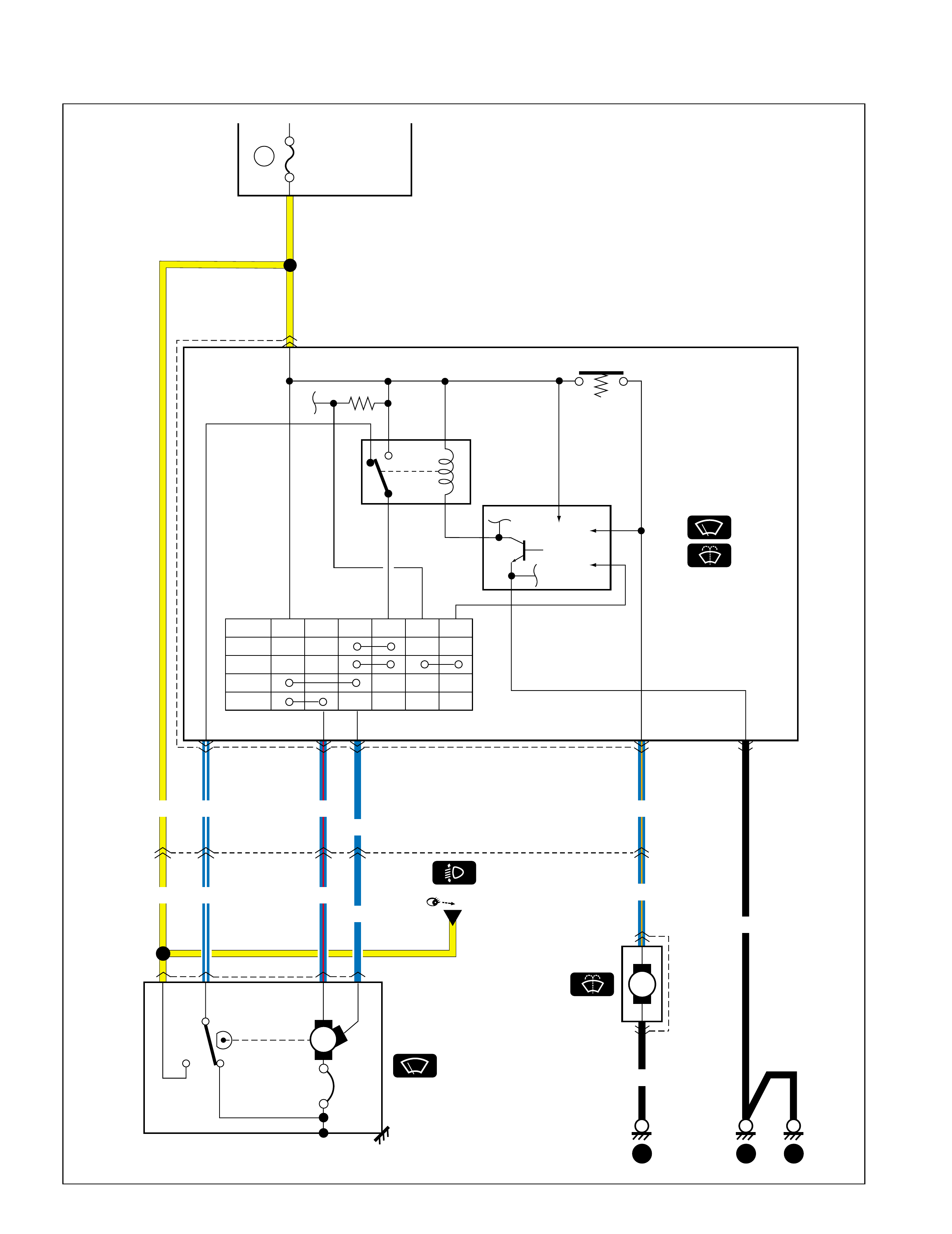
B-1 Windshield wiper & washer (with intermittent wiper)
E25
M
Switch
2
1
YEL
YEL
8
4
G34
E35 7 5 6
15A
G28
Operate Stop
H
L
E27 43 12
Washer switch
Switch
Control circuit
12V
Relay
OFF
INT
LP
HI
B3 +2 +1 AS INT1 INT2
21 WIPER. WASHER Fuse box
2
534 15
BLU/ORN
BLU/ORN
BLK
10
BLK
13 15
G26
M
"D-2"
BLU/WHT
BLU
BLU/RED
BLU/WHT
BLU
BLU/RED
99512-70H10-GHE.book Page 10 Friday, September 26, 2003 3:16 PM

B-2 Rear wiper and washer
M
O06 E26
4
2
4 3
G45 4 1
5 3
L23
O01 65
BLU
YEL
ORNYEL/RED
ORN GRN/YEL
YEL
ORN GRN
15A
WIPER.
WASHER
3
M
2
1
5
G38
L28 G34
E35
6 14
O01
L23 2
BLK
WASH IG WA LD
OFF
ON
WASH
G29 1
Fuse box 21
BLK
BLK BLK
10132120 15
Relay
Switch
99512-70H10-GHE.book Page 11 Friday, September 26, 2003 3:16 PM
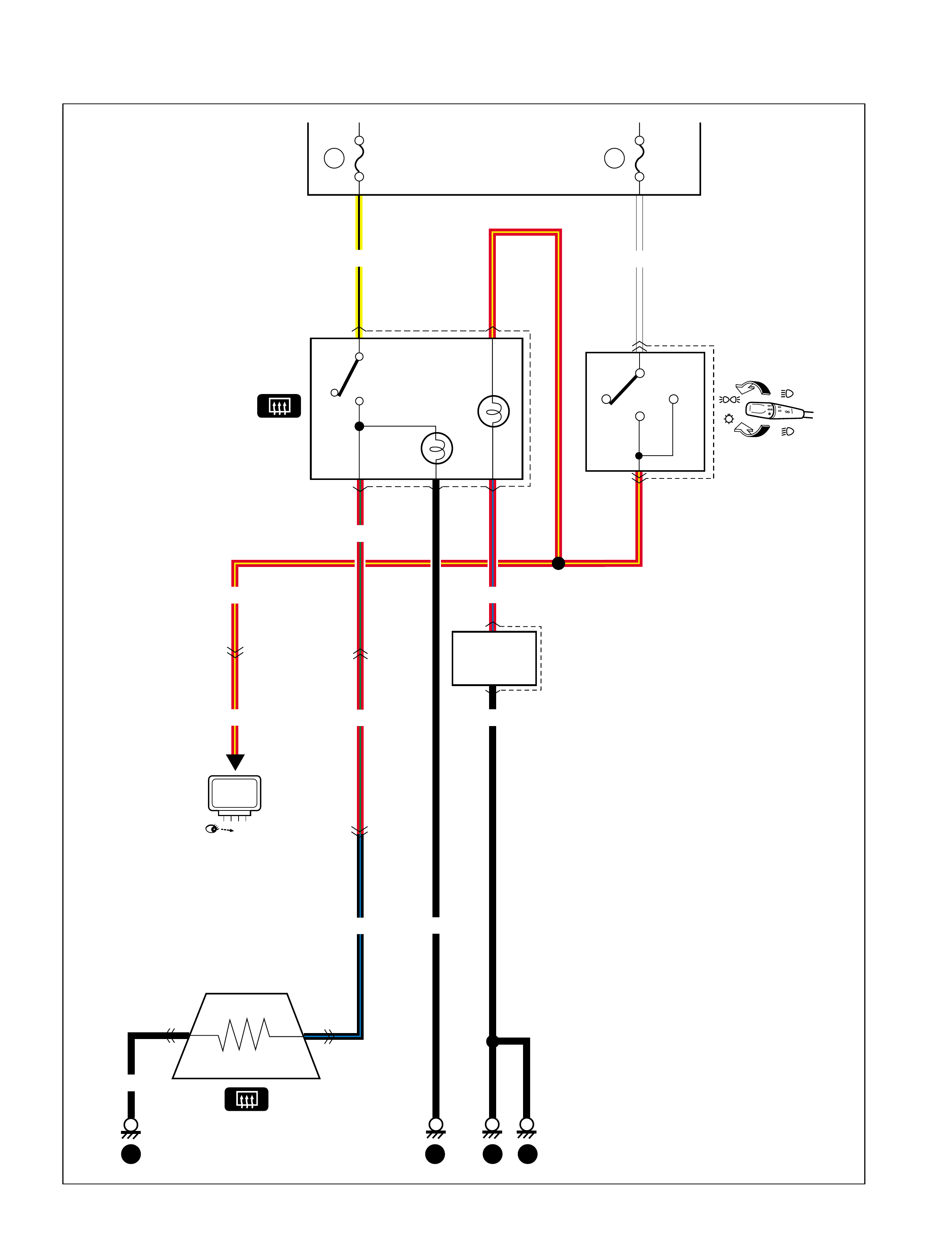
B-3 Rear defogger
O05O12
1
1
YEL/BLK
3
L23
O01
19
G37
L07
15A
G12 12
436
BLK
RED/YEL
RED/YEL
1
G03
C46
Fuse box REAR
DEFG
Switch
12 10A TAIL
15
6
7
13
1422 15
WHT
TAIL
OFF
HEAD
G26
G49 3
4
RED/GRN
BLK/BLU
RED/GRN
BLK
RED/BLU
BLK
ILL controller
"A-6"
ECM
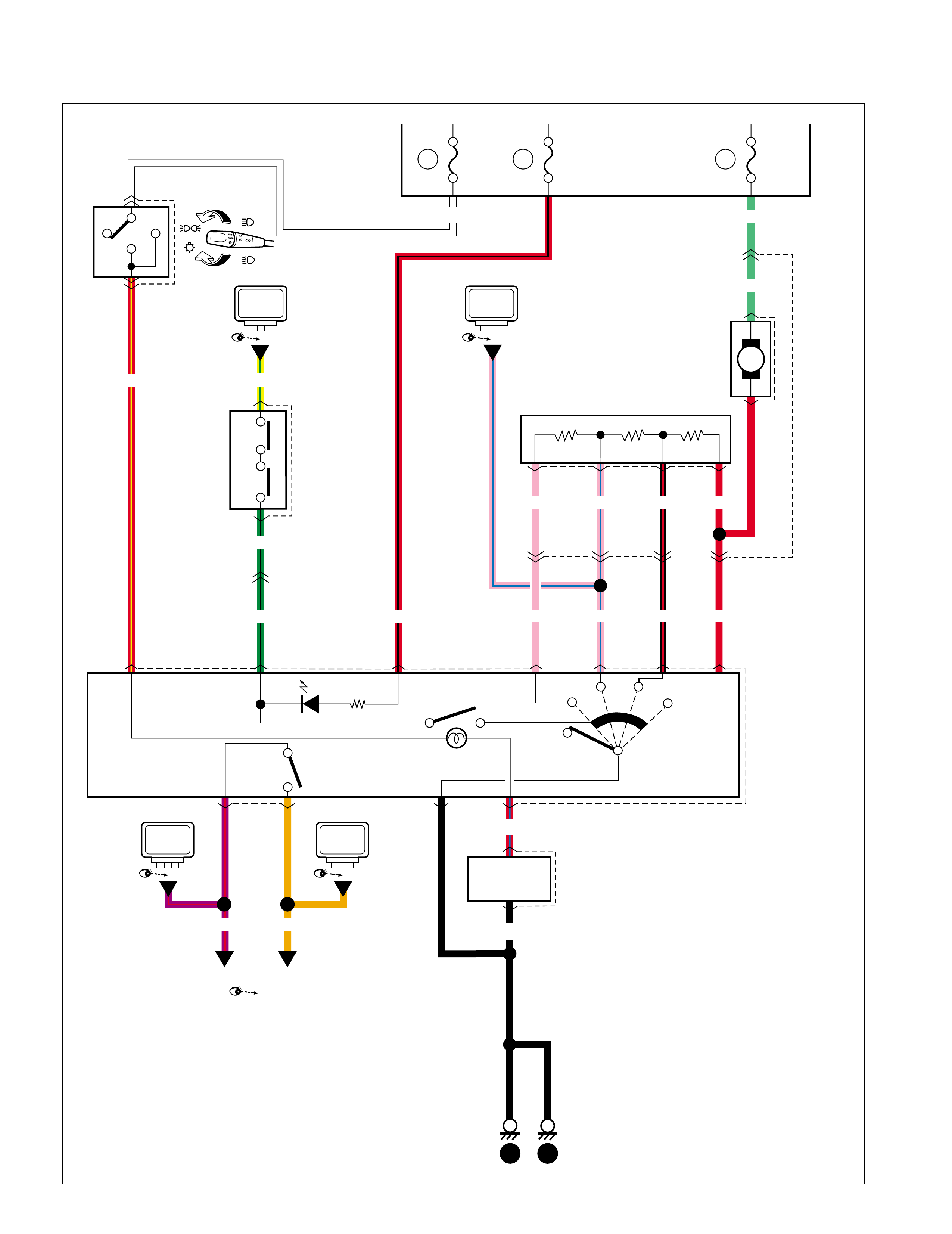
99512-70H10-GHE.book Page 12 Friday, September 26, 2003 3:16 PM
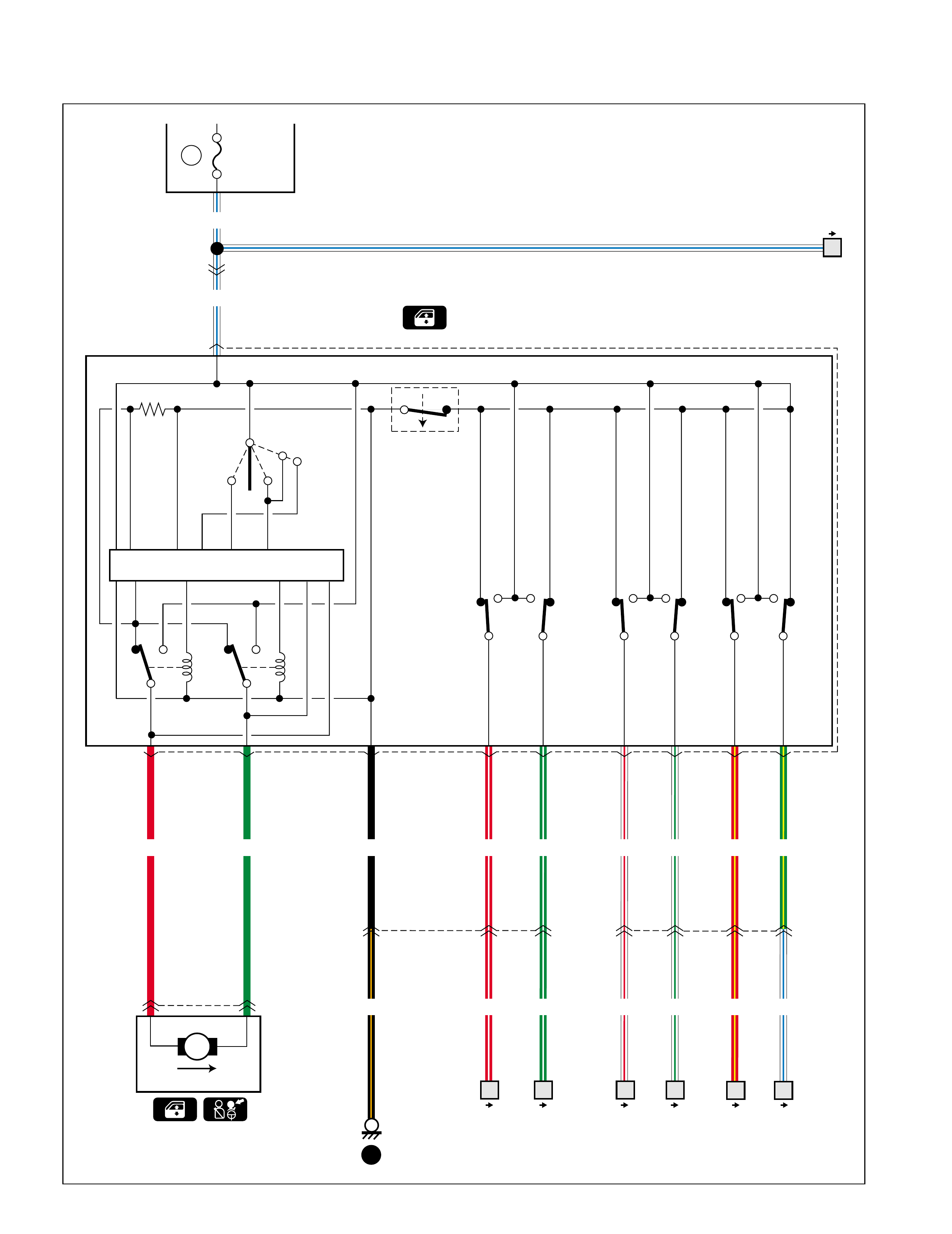
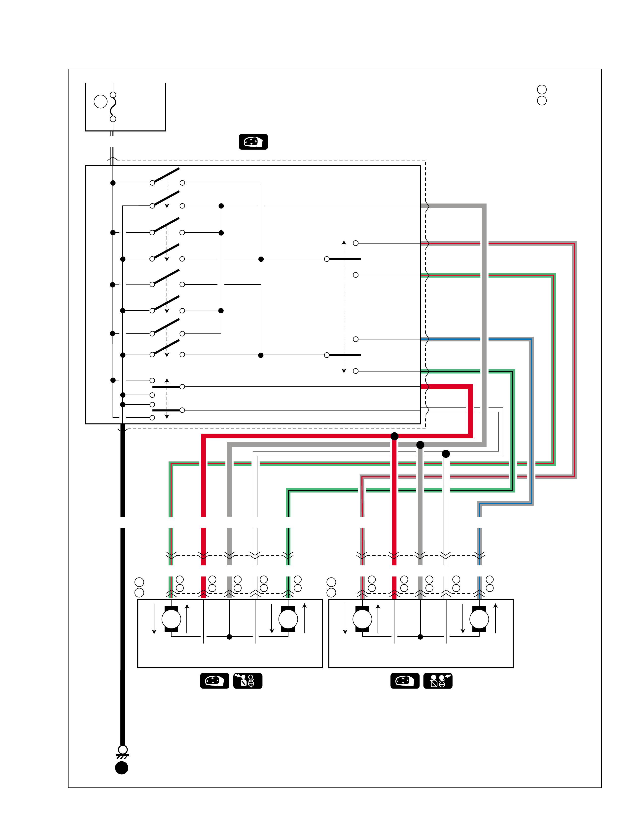
B-4 Power window
G10
J01
2 3
1
1
76 16
67
14
J06
L06
45
J01
G10 25
M
J02
UP
12
30A P/W
J04
UP
LOCK
UP DOWN
UP DOWN UP
DOWN UP
DOWN
WHT/BLU
WHT/BLU
RED GRN BLK RED/WHT GRN/WHT WHT/RED WHT/GRN RED/YEL GRN/YEL
RED/WHTBLK/ORN GRN/WHT WHT/RED WHT/GRN RED/YEL WHT/BLU
25 Fuse box
8
34 7 12
Main switch
Window lock switch
Passenger
Right
rear Left
rear
AUTO
DOWN
Front
Auto circuit
16
91056
DOWN
99512-70H10-GHE.book Page 14 Friday, September 26, 2003 3:16 PM
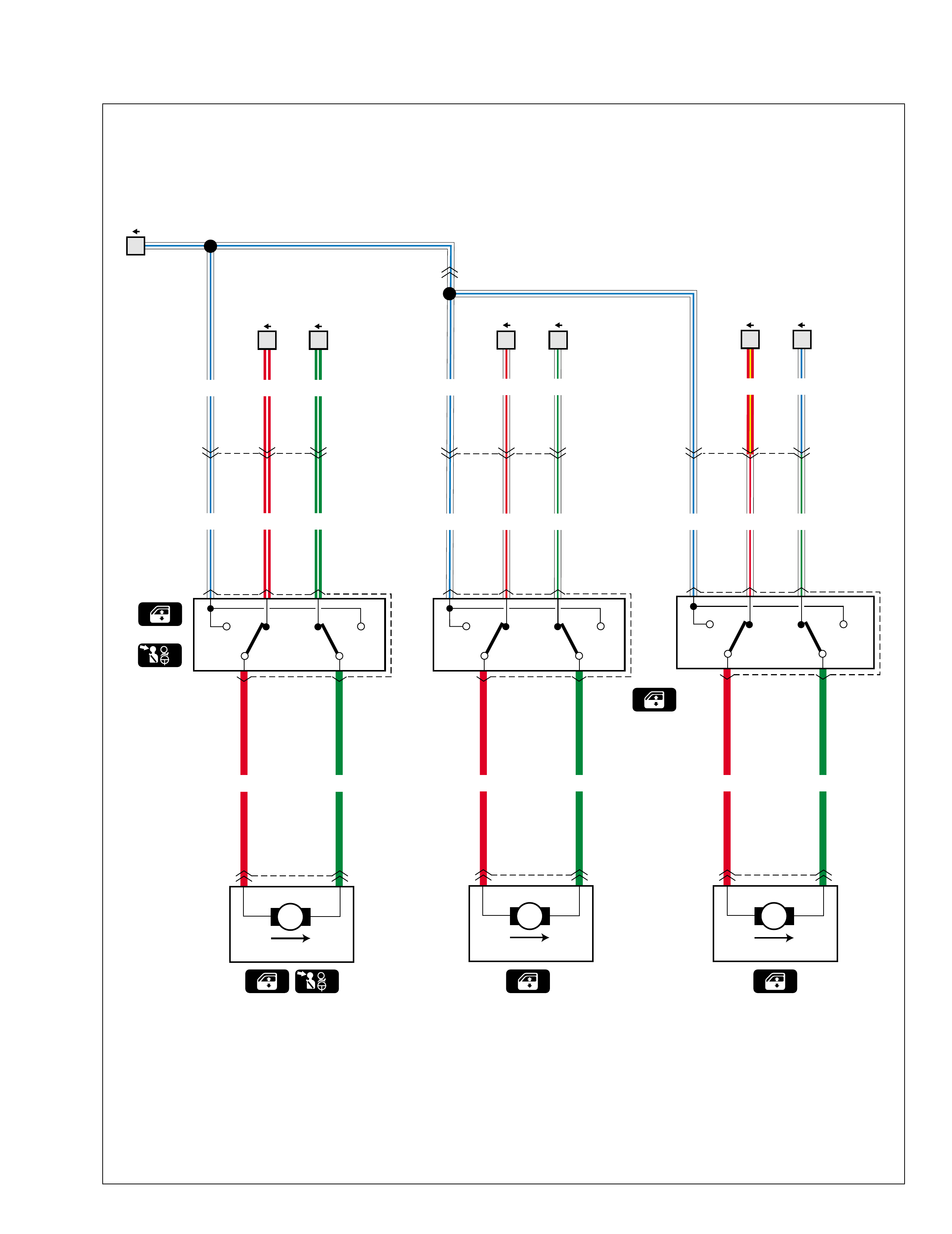
J10
G01
J07
UP DOWN
J17
L13
J16
UP DOWN
1
32
L09
J12
25
314
25
514
314
132 514
2
G38
L28
J13
UP DOWN
25
314
M
J08
UP
12
M
J15
UP
21
M
J19
UP
21
WHT/BLU WHT/BLU
WHT/BLU WHT/RED WHT/GRN
WHT/BLU RED/WHT GRN/WHT WHT/BLU WHT/RED WHT/GRN
WHT/GRN WHT/BLU
RED/WHT GRN/WHT
RED GRN
RED GRN RED GRN
Front Rear (R)
Front switch
Rear switch
(R) (L)
WHT/RED RED/YEL
4 5 67
Rear (L)
99512-70H10-GHE.book Page 15 Friday, September 26, 2003 3:16 PM
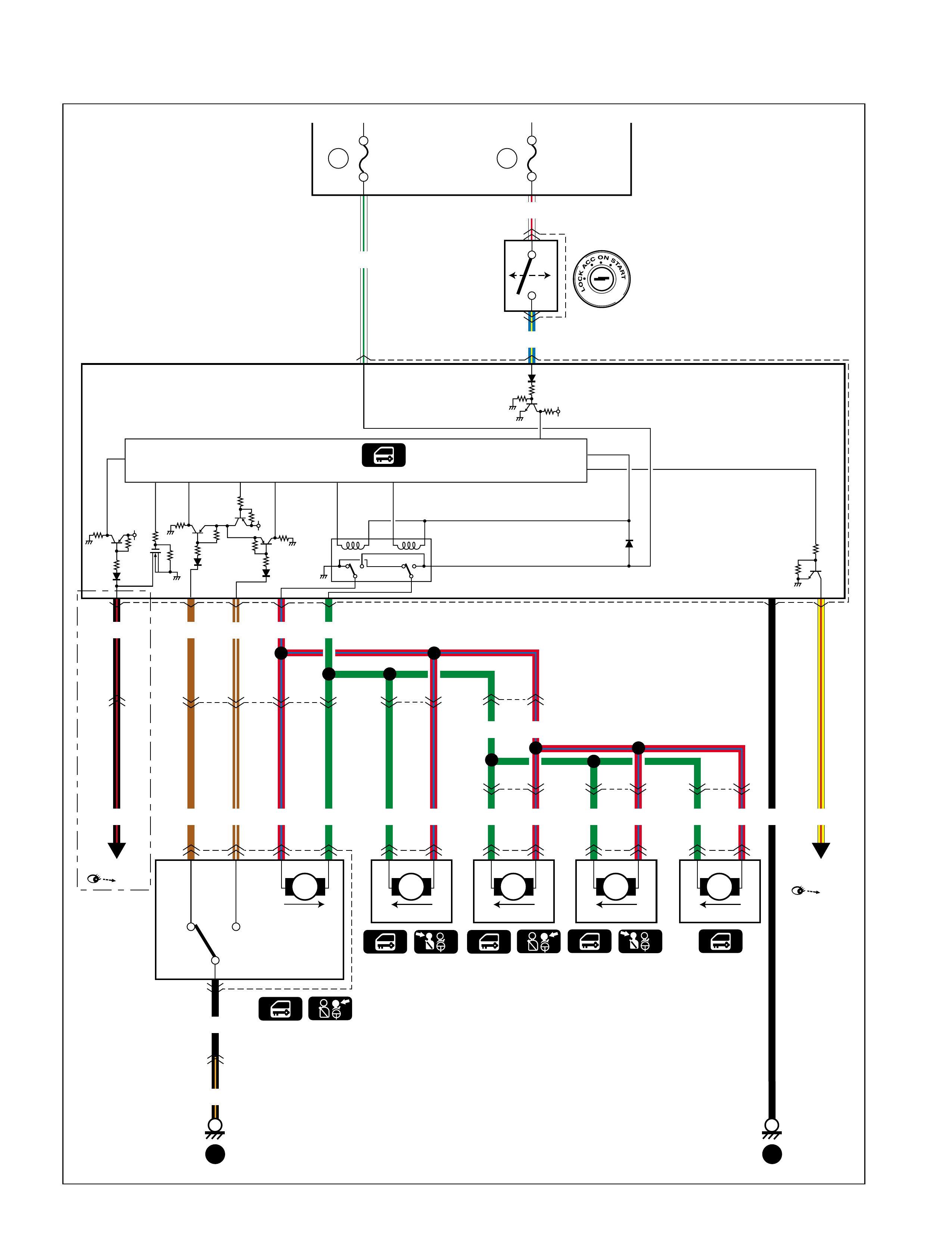
B-5 Power door lock (With keyless entry)
7
9
410 11 12
6
J01
G10
12 2
8
13
G10
J01 8
G40
9
G38
L28
20A
DOOR
LOCK
BRN/WHT
BLK/RED RED/BLU
WHT/GRN
2
5V
5V 5V
WHT/RED
BLU/YEL
BLK
BLK/ORN
15A
RADIO.
DOME
J05
M
LOCK
LOCK UNLOCK
1
5
3
2
5
G01
J07 44
M
LOCK
J11 21
3
G37
L07
3
6
M
LOCK
J14 12
6
L13
J16 3
L09
J12
M
LOCK
J18 12
25
L22
O02
M
LOCK
O09 34
RED/BLUGRN
RED/BLURED/BLURED/BLUBRN/WHTBRNBLK/RED GRNGRN RED/BLUGRN RED/BLUGRNGRN
4
G31
1
2
BLK
13 16
GRNBRN
1416
Fuse box
Rearend
Front
Front
Diode #2
Keyless entry
model
Rear
Rear
"D-7"
Controller
5
YEL/RED
Hazard
switch
"D-8"
99512-70H10-GHE.book Page 16 Friday, September 26, 2003 3:16 PM
B-7 Remote controlled mirror
WHT/BLK
LT GRN/RED
LT GRN/RED
9
G01
J07 610 12 7 11
G10
J01 95 15 10
15A CIGAR Fuse box
G44 5
7
8
2
1
9
4
3
6
DOWN
L
UP
R
R
L
SET
RETRACT
J09
J22
M1 M2
U
P
D
O
W
N
L
E
F
T
R
I
G
H
T
NOT
USED NOT
USED NOT
USED NOT
USED
M1 M2
U
P
D
O
W
N
L
E
F
T
R
I
G
H
T
BLK
23
14
Switch
GRY/BLU
GRY/BLU
LT GRN/BLK
LT GRN/BLK
RED
RED
WHT
WHT
GRY/RED
GRY/RED
WHTGRYGRY
GRY
RED
Type 1
Type 2&3
A
B
2
2
A
B
A
BJ03
J21
A
B
6
5
A
B
5
7
A
B
1
1
A
B
7
6
A
B
2
2
A
B
6
5
A
B
5
7
A
B
1
1
A
B
7
6
A
B
99512-70H10-GHE.book Page 17 Friday, September 26, 2003 3:16 PM

B-9 Horn
17
10
15A HORN
12
GRN/BLK
GRN/WHT
G34
E35
G36 1
G25 96
10 8
BLK
BLU/YEL
GRN/WHT
Fuse box
Horn relay
Combination switch (Horn)
<Type 1&2>
E20 2
1
H
GRN/WHT
<Type 3>
E40 1
H
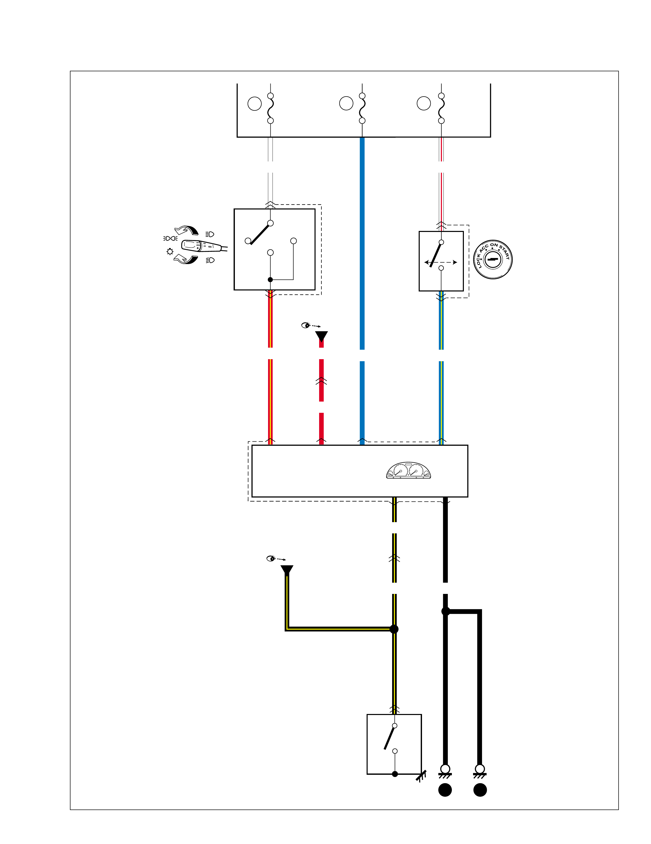
99512-70H10-GHE.book Page 18 Friday, September 26, 2003 3:16 PM

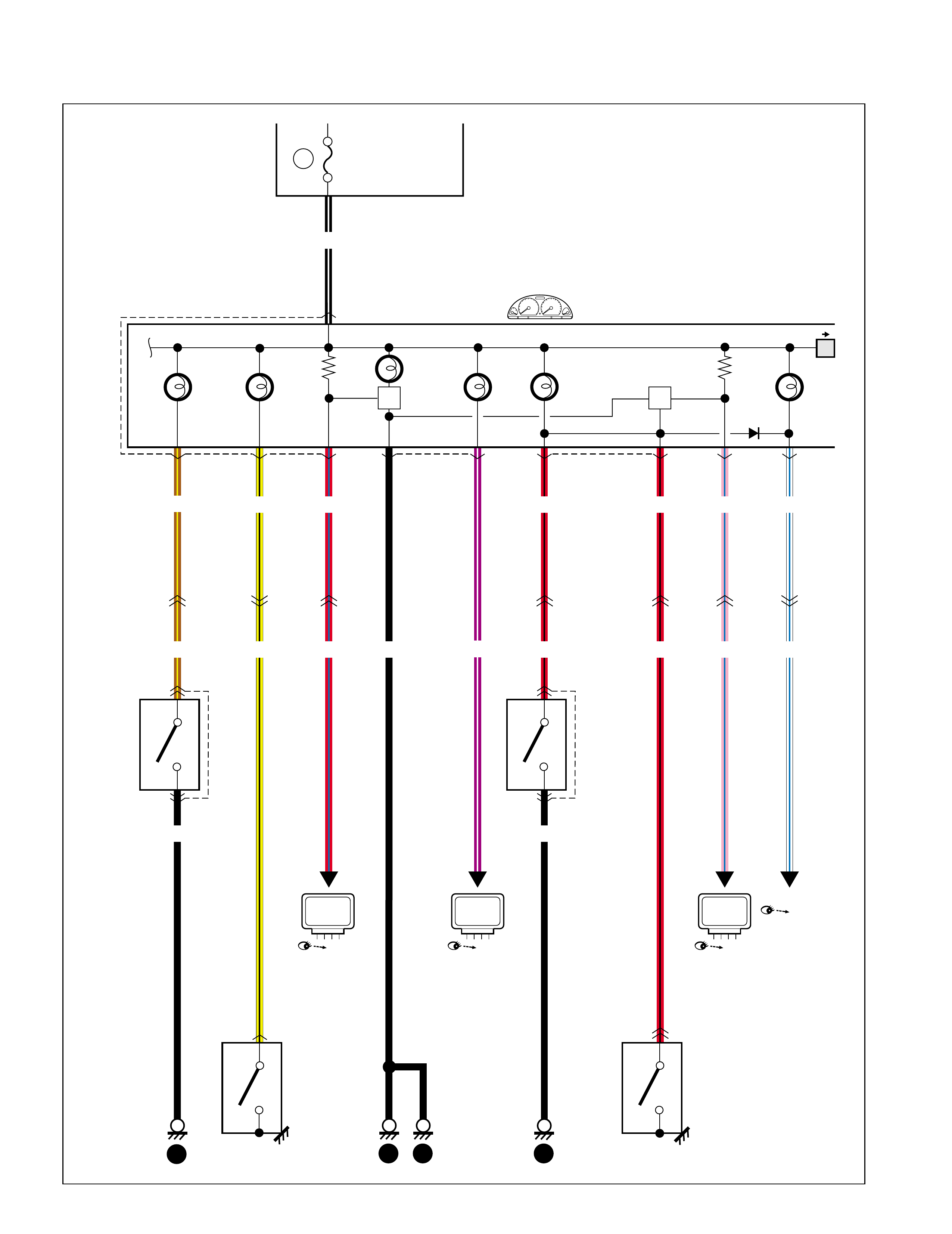
C-1 Combination meter
BLK/ORN
G21 G22 G21
ILL
TACHO
TEMP
10
7
5G22 14915
11
6
13
FUEL
BLU
RED/YEL
4
14
G03
C46 G03
C46
13
G37
L07
6
G03
C46
15A RADIO.
DOME
BLK/ORN
PPL
YEL/REDBRN YEL/BLU
YEL/BLU YEL/RED
BLK/ORN PPL
WHT/RED
2
L19
L29
L30 1
2
YEL/RED
PPL
BLK/ORN
C20
2
1 3
BLK/RED
5
5
C46
G03
1
10A METER
26 16
13 15 5
Fuse box
Main relay
M/T
Fuel gauge
Multi information
display
ECT sensor
Speed meter &
odo meter circuit
Warning buzzer
Vehicle speed
sensor
G49 3
4
RED/BLU
BLK
10A
TAIL
OFF HEAD
G26
TAIL
15
6
7
WHT
"F-4"
ILL controller
"A-6"
"A-6"
"G-3"
"A-6"
"F-2"
"A-6"
"G-1"
"G-3"
P/S
Cont.M
ECM
"G-1"
TCM
P/S
Cont.M
TCM
ECM
99512-70H10-GHE.book Page 19 Friday, September 26, 2003 3:16 PM
C-2 Combination meter (indicator lamp)
BEAM
TURN (R)
TURN (L)
E12
13
G21 1
212
9
WHT/BLU
WHT/BLU
BLU/YELGRN/RED
RED
11
E35
G34
15A
1
BLK
7
13 15
Main fuse
"D-1"
"D-8"
99512-70H10-GHE.book Page 20 Friday, September 26, 2003 3:16 PM
C-3 Combination meter (warning lamp)
OIL
CHECK
ENGINE
CHARGE
BELT
3
G22
G21 G22 G21
10
43211 7
1
EBD/
BRAKE
6
RED/BLK
PPL/WHT
RED/BLK
6
G37
L07 2
G34
E35
BRN/YEL
10A METER
BLK/WHT
10
PNK/BLU
BLK
RED/BLU
11
G35
E36
7
G03
C46
ABS
BLK
1
2
E17
1
2
L17
C30
3
G34
E35
10
G37
L07
YEL/BLK
BRN/YEL RED/BLUYEL/BLK BLK
1
L11
G22
8
G03
C46
5
WHT/BLU
RED/BLK RED/BLK PNK/BLU WHT/BLU
1
19 13 15
26
10
Fuse box
Oil pressure
switch
Generator
Seat belt
switch Brake fluid
level switch
Parking brake switch
ABS
CIRCUIT
EBD
CIRCUIT
ABS
Cont.M
"G-5"
ECM
"A-6"
ABS
Cont.M
"G-5"
"A-2"
99512-70H10-GHE.book Page 22 Friday, September 26, 2003 3:16 PM
AIRBAG
EPS
21
G22 G21
O/D OFF
YEL
YEL/BLK
YEL/BLK RED/BLK
3
G39
L45
4
1
A/B
Cont.M
"G-4"
P/S
Cont.M
"G-3"
TCM
"G-1"
99512-70H10-GHE.book Page 23 Friday, September 26, 2003 3:16 PM
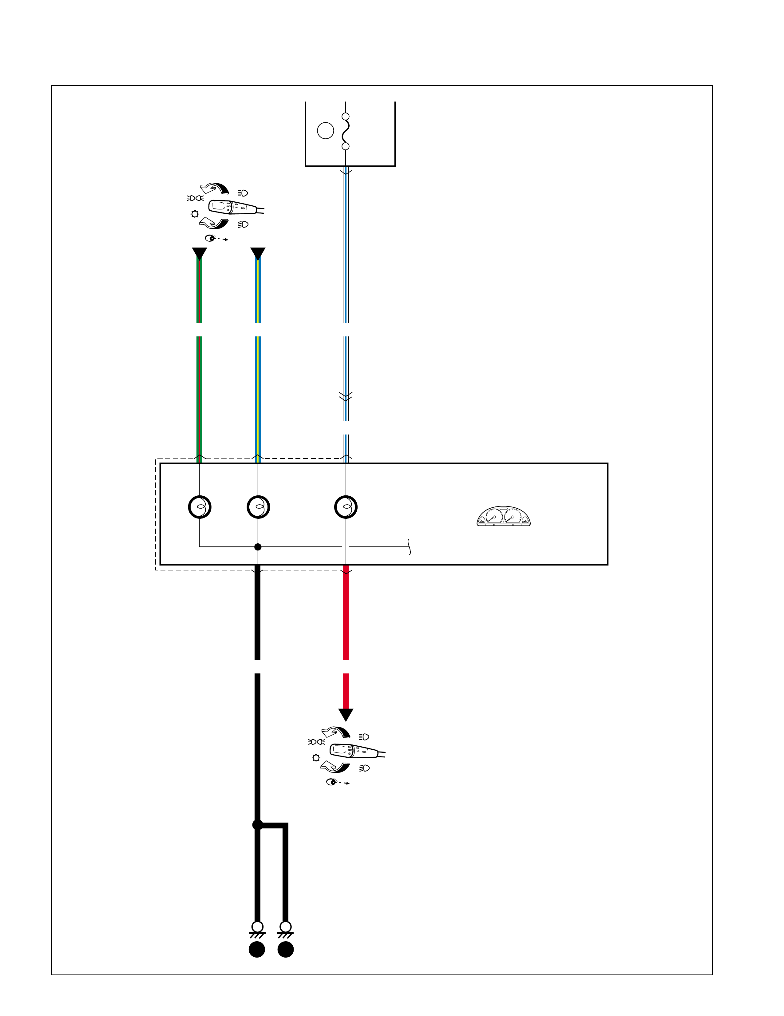
D-1 Headlight
E05 E23
WHT/RED
RED/WHT
WHT/BLU
3
21 12
3
RED/WHT WHT
RED
WHT/BLU
RED/YEL
BLK RED/YEL RED/YEL
2
E12 1
15A 15A 10A
16
G34
E35
16
G37
L07
G21
BEAM
12
9
RED/YEL
Lighting switch
G26
10 9
11
E35
G34
E35
G34
Fuse box
Main fuse TAIL
Dimmer & passing switch
Front position light
License plate light
A/T shift ILL
Brake light
Headlight (L) Headlight (R)
7 6
15
13 15
6
L22
O02
4
57
96
RED
"D-3"
"D-3"
"D-3"
"D-6"
HEAD
PASS
LO
Hi
TAIL
OFF
99512-70H10-GHE.book Page 24 Friday, September 26, 2003 3:16 PM
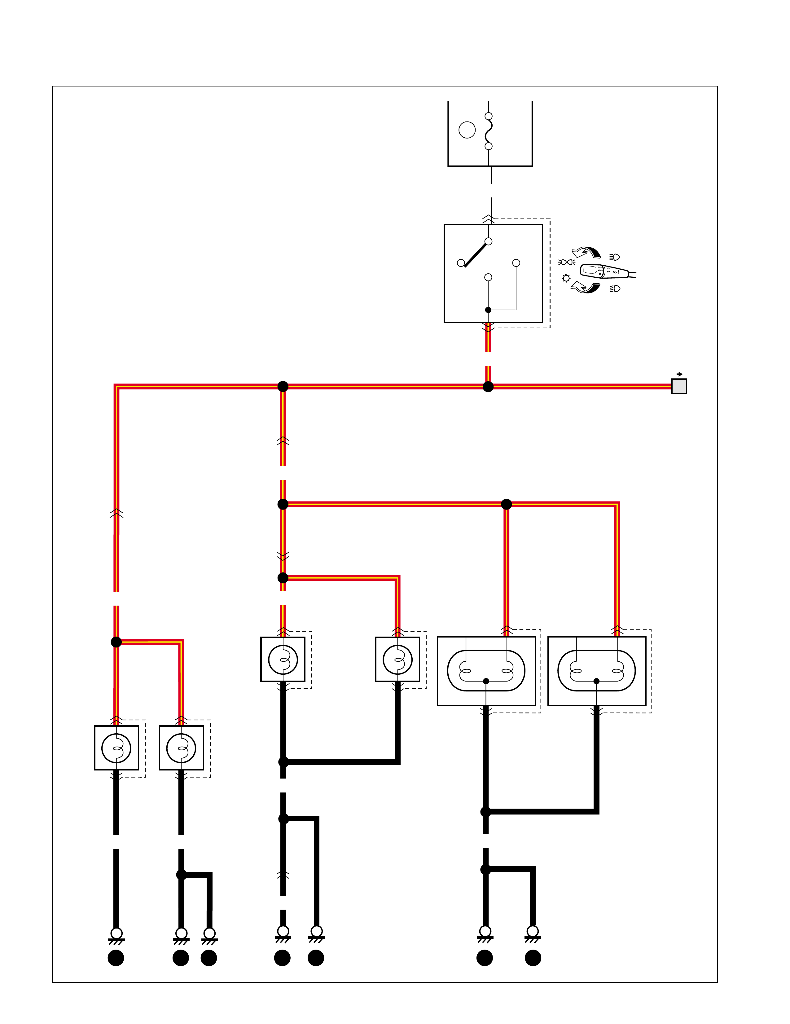
D-3 Position, tail and license plate light
O07
E03 L43 2
1
L44 2
1
16
G37
L07
2
O01
L23
6
L22
O02
16
G34
E35
10A
TAIL
OFF
HEAD
G26
2
1E24
2
11
2
Fuse box
Front position
light
TAIL
License plate
light#1 License plate
light#2
(L) (R)
(L) (R)
15
6
7
9 8 11 20 21 18 20
O08 1
2
RED/YEL
WHT
RED/YEL
RED/YEL
BLK
RED/YEL
RED/YEL
BLK BLK
BLK
BLK
RED/YEL
Brake light
99512-70H10-GHE.book Page 25 Friday, September 26, 2003 3:16 PM
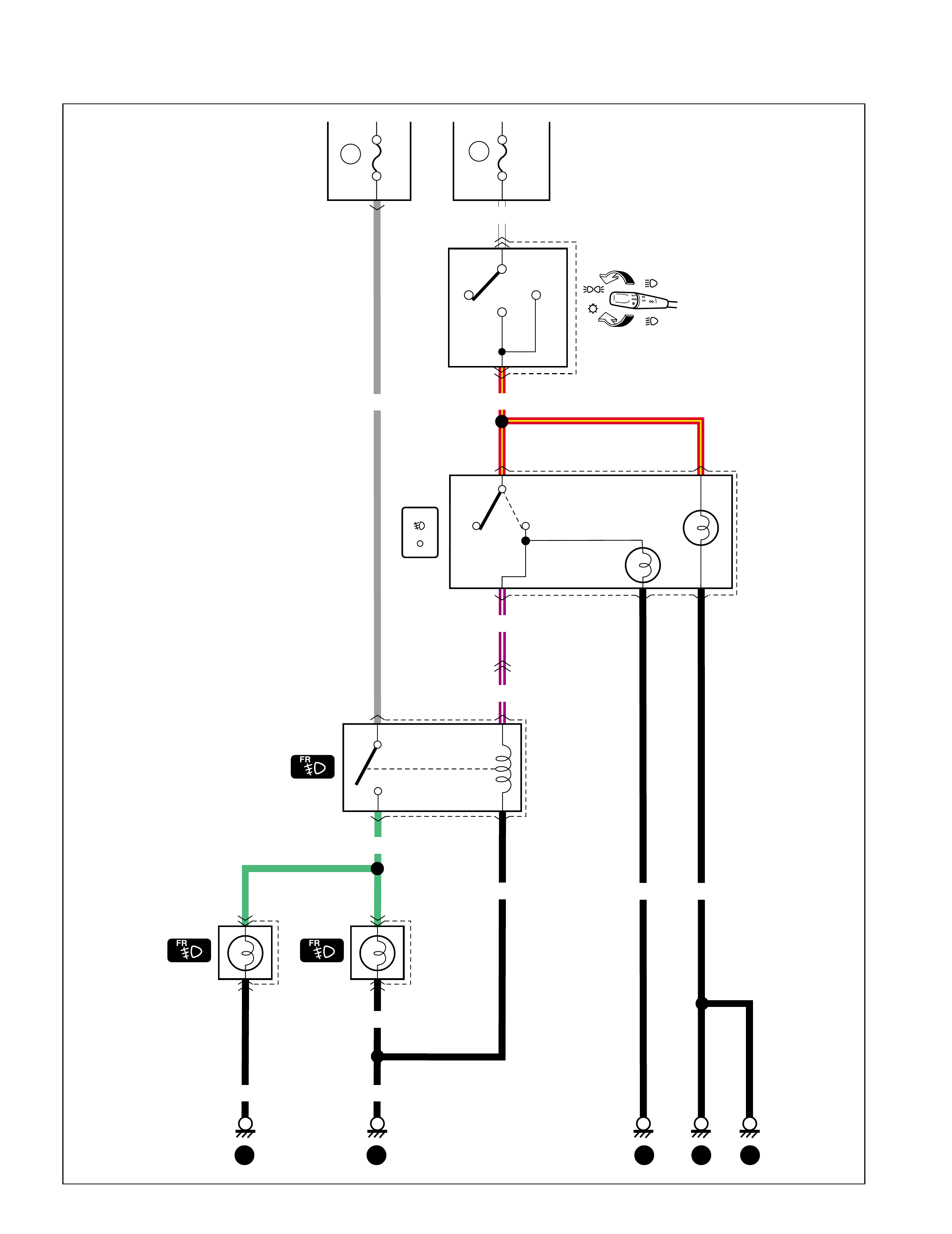
D-4 Fog light
E16
G46
E13
PPL/WHT
PPL/WHT
RED/YEL
LT GRN
5 6
4
1
12
4
2
3
1
E01
E21
BLK
20A
1
2
1
2
BLK
BLK BLK
15
G34
E35
ILL
BLK
BLK
Relay
PUSH
LOCK
FREE
8
151314
710
10A
TAIL
OFF
HEAD
G26
Fuse box
TAIL
15
7
6
WHT
Main fuse
GRY
(L)(R)
99512-70H10-GHE.book Page 26 Friday, September 26, 2003 3:16 PM
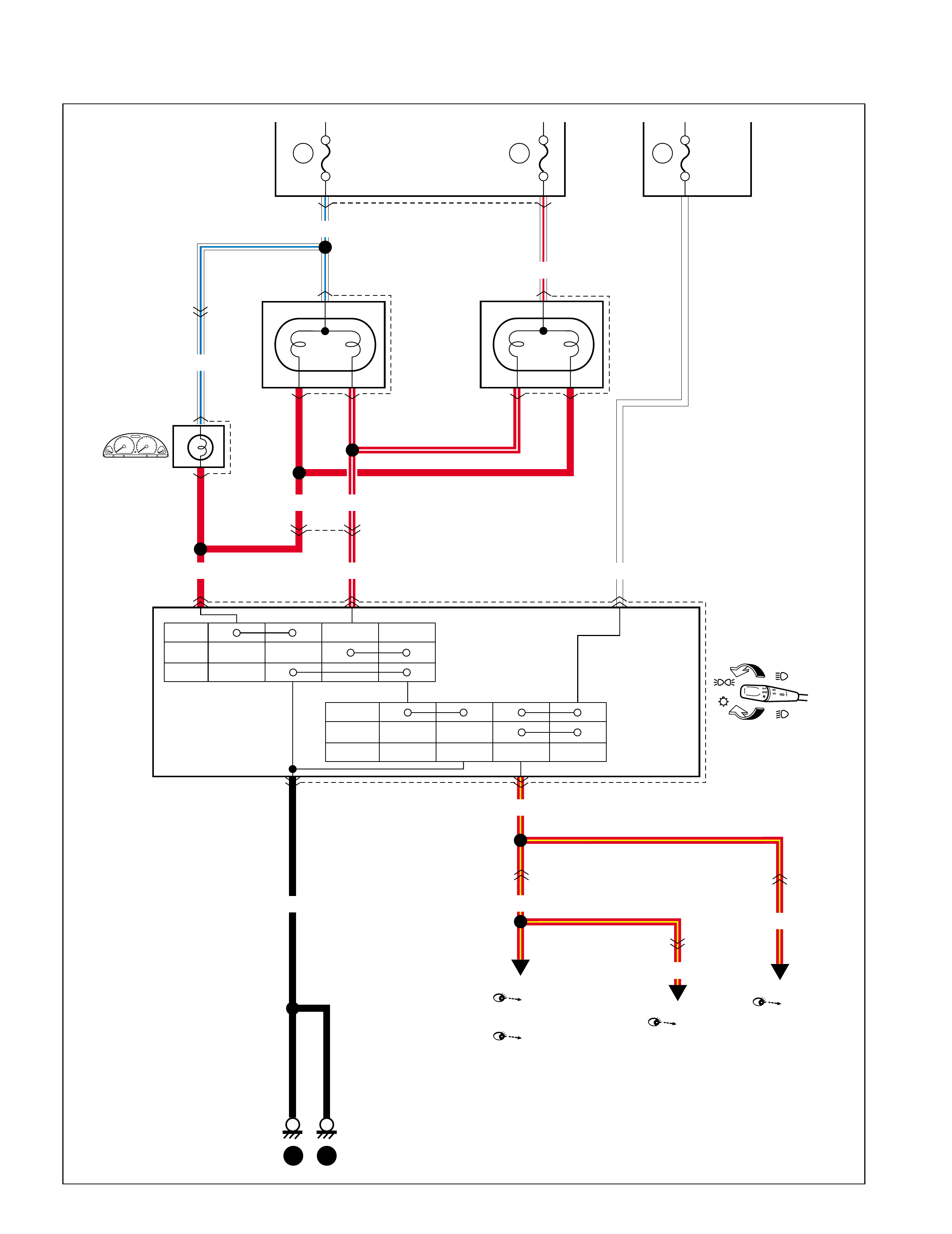
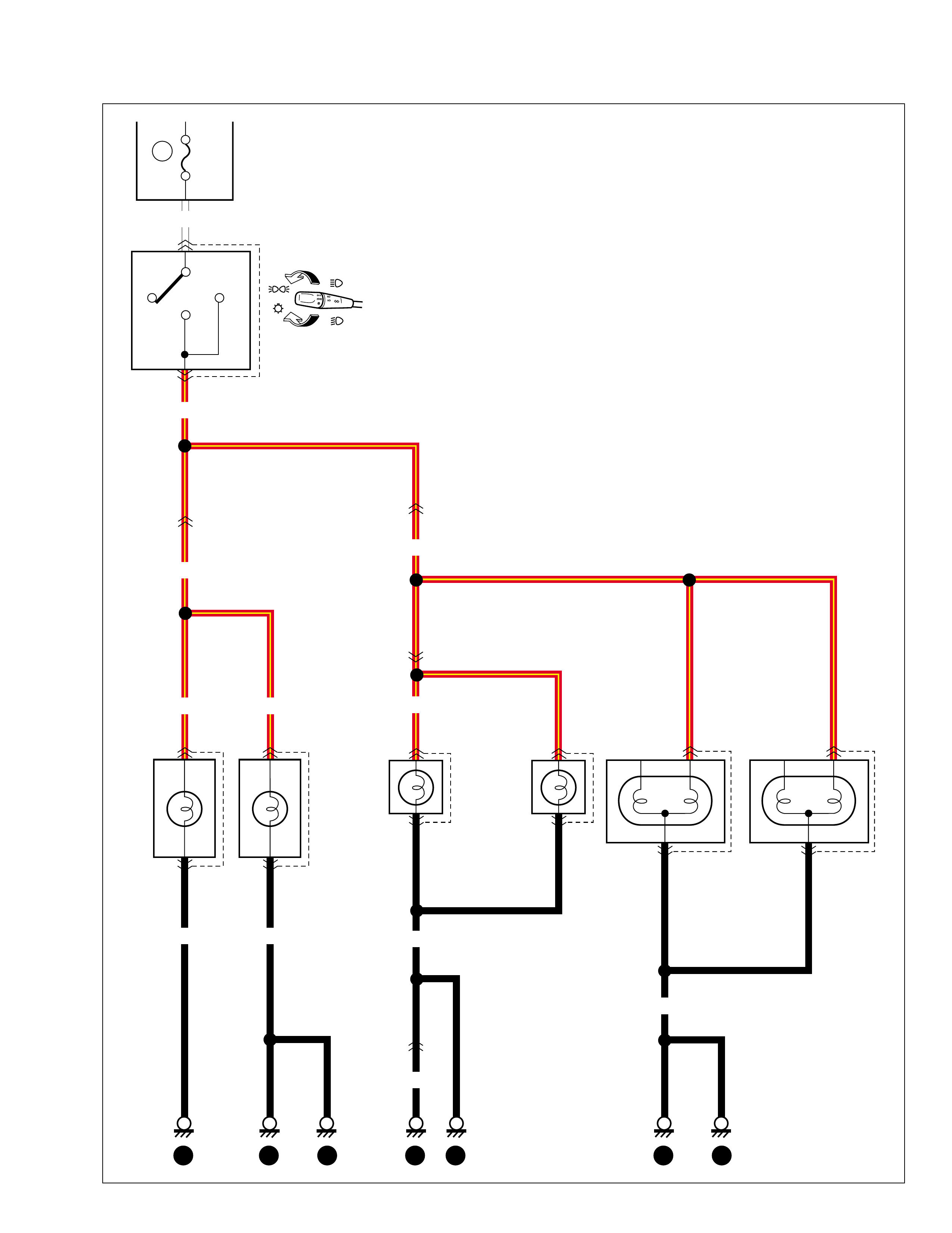
D-6 Illumination light
WHT
10A
TAIL
TAIL
OFF
HEAD
G26
RED/YEL
16
G34
E35
RED/YEL
15
Fuse box
6
7
E03 1
BLK BLK
9
2
E24 1
8
2
Front
position light
(L) (R)
11
O07 L43 2
1
L44 2
1
16
G37
L07
2
O01
L23
6
L22
O02
1
2
License plate
light#1 License plate
light#2
(L) (R)
20 21 18 20
O08 1
2
RED/YEL
BLK
BLK
BLK
RED/YEL
Brake light
1
99512-70H10-GHE.book Page 28 Friday, September 26, 2003 3:16 PM
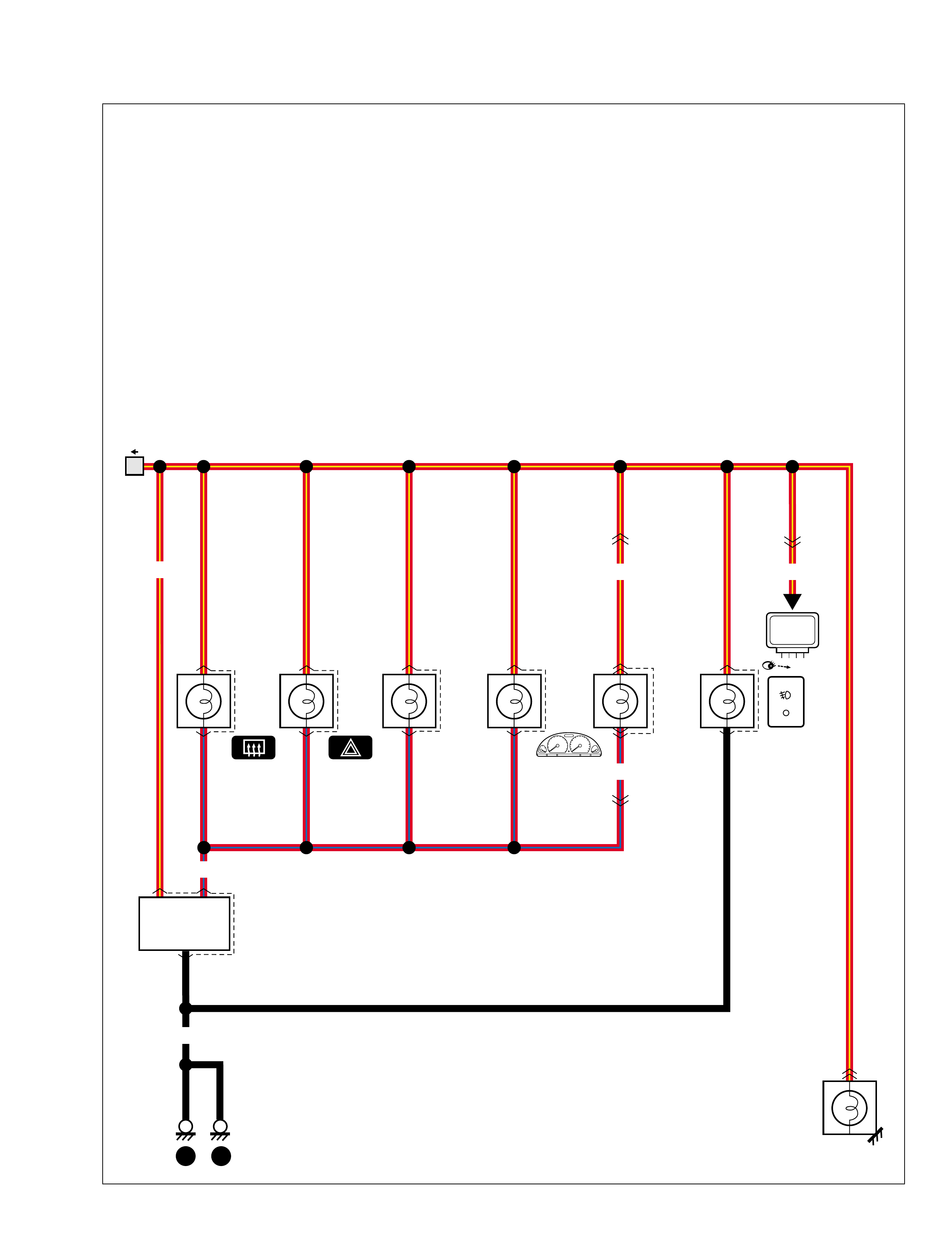
RED/YEL
1
G03
C46
RED/YEL
16
G37
L07
20
L07
G37
RADIO
13 15
G12 2
6
G49 32
1
Switch Switch
ILL controller
BLK
G13 5
4
1
G14 4
1Blower fan
& A/C switch A/T shift
ILL
G21 7
5
RED/BLU
L08 2
5
RED/BLU
G46 6
2
G09 8
"A-6"
RED/YEL
ECM
99512-70H10-GHE.book Page 29 Friday, September 26, 2003 3:16 PM
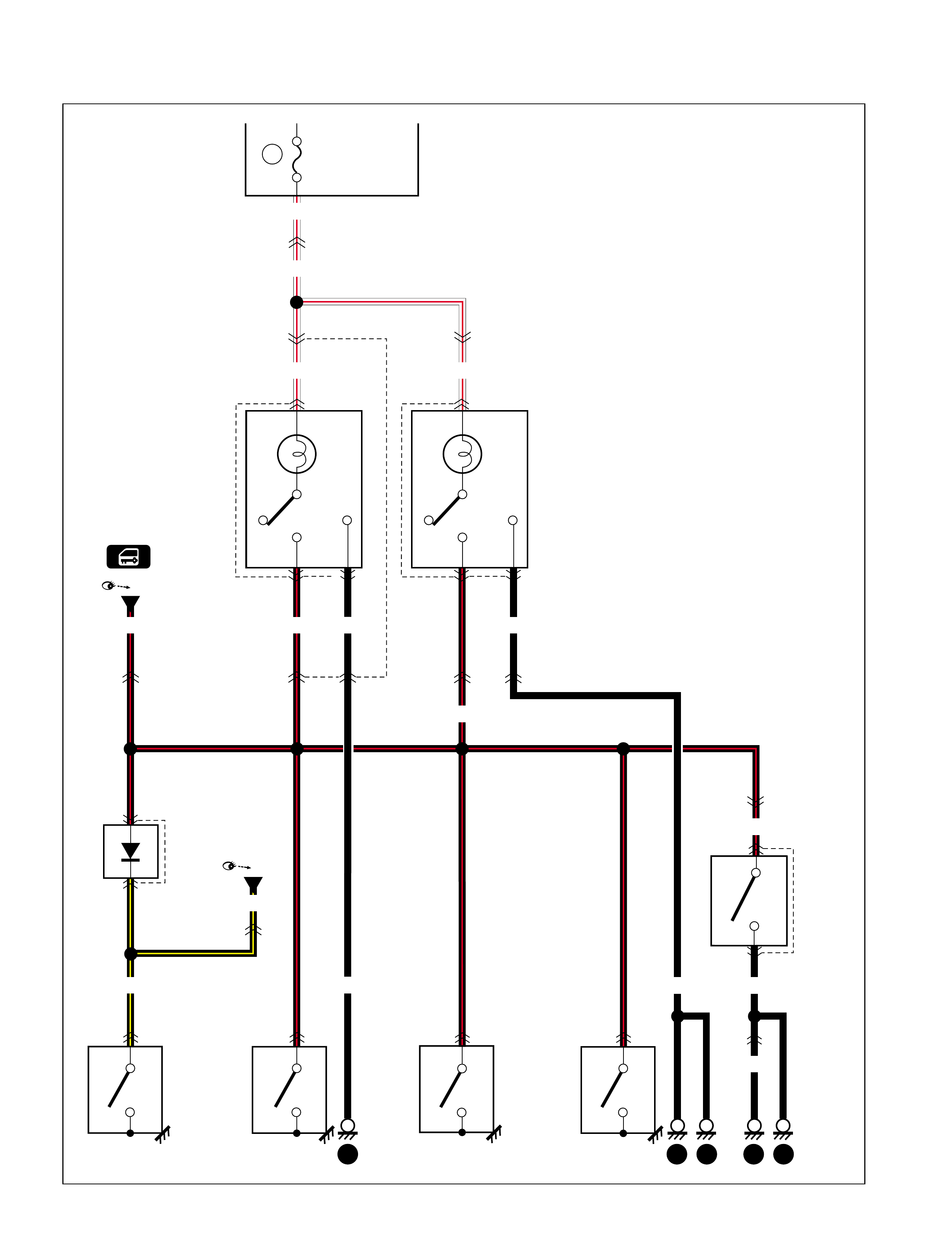
D-7 Interior light
BLK/YEL
WHT/RED
WHT/RED
WHT/RED
BLK/YEL
L14
L10 11
2
L02
1
CLOSE
OPEN
CLOSE
OPEN
L16 1
CLOSE
OPEN
CLOSE
OPEN
CLOSE
OPEN
L20 1
DOOR
OFF
ON
13
2
K03
DOOR
OFF
ON
13
2
O03
3
L01
K01 1
L22
O02
17
G37
L07
2
O01
L23
4
O01
L23
9
G38
L28 K01
L01 2 1 4
O02
L22
18
G37
L07
3
L22
O02
15A
RADIO.
DOME
BLK/RED
BLK/RED BLK/RED BLK
O09
1
2
BLK
BLK/RED
WHT/RED
16
Fuse box
Interior light Interior light (REAR)
BLK
BLK
2018 2120
19
Diode
#2
Front door switch
(R) (L) Rear door switch
(R) (L)
Controller
Warning buzzer
controller
Rearend
door
switch
"B-5"
BLK
"F-4"
BLK
99512-70H10-GHE.book Page 30 Friday, September 26, 2003 3:16 PM

D-8 Turn signal and hazard warning light
1
2378
465
213
5
Fuse
box 15A
17 HORN 10A
26 METER
GRN/WHT
GRN/YELBLU/RED
GRN/WHT
GRN/WHT
BLU
GRN/RED
GRN/RED
BLU/YEL
GRN/RED BLU/YEL
BLU/YEL
GRN/REDGRN/REDBLKRED/BLUBLK BLU/YELBLU/YEL
GRN/REDYEL/REDRED/YEL
YEL/RED
BLU/YEL
BLKBLKBLK
BLKBLKBLKBLKBLK BLK
G27
G42
Turn signal
switch
R
N
L
Turn signal
relay
G37
L07 12 11
G35
E36 13 12
L27
E22E04
G13
L21
1
4
22
11
4
1
Tail light
(L) (R)
18111513 89 20
"C-2"
Turn signal
light
(L) (R)
G49 3
48
57
4
ILL
controller
Controller
"B-5""D-6"
Hazard
switch
ILL
99512-70H10-GHE.book Page 31 Friday, September 26, 2003 3:16 PM
D-9 Brake light
PNK
PNK
GRN/WHT
8
G37
L07
L43
L44 3
1
3
1
10A
STOP
BLKBLK
1
L23
O01
1
O04
O10
O11 2
1
2
BLK
GRN
2
O01
L23
GRN/WHT
2
L05
E33 7
L07
G37
11
G03
C46
GRN/WHT
GRN/WHT
BLK
GRN/WHT
Fuse box
18 2020 21
14
A/TM/T
L04
L03
RELEASE STEP RELEASE STEP
Brake light
switch For L03,L04:See the wire colors to identify the
terminals.There are some kinds of connector
and terminal layout.
High mounted
stop light
Brake light
(L) (R)
ABS
Cont.M
"G-5"
ECM
"A-6"
TCM
"G-1"
99512-70H10-GHE.book Page 32 Friday, September 26, 2003 3:16 PM
D-10 back-up light
M/T A/T
PRND2L
7
17
G03
C46
16
C46
G03
15
G37
L07
BLK
RED/BLK
RED/BLK
RED
RED
RED RED
10A
L27 3
4
L21 3
4
8
C15
1
2
C51
BACK
Back-up light
switch
Fuse box
Back-up light
(L) (R)
20
18 20
Transmission range sensor
99512-70H10-GHE.book Page 33 Friday, September 26, 2003 3:16 PM
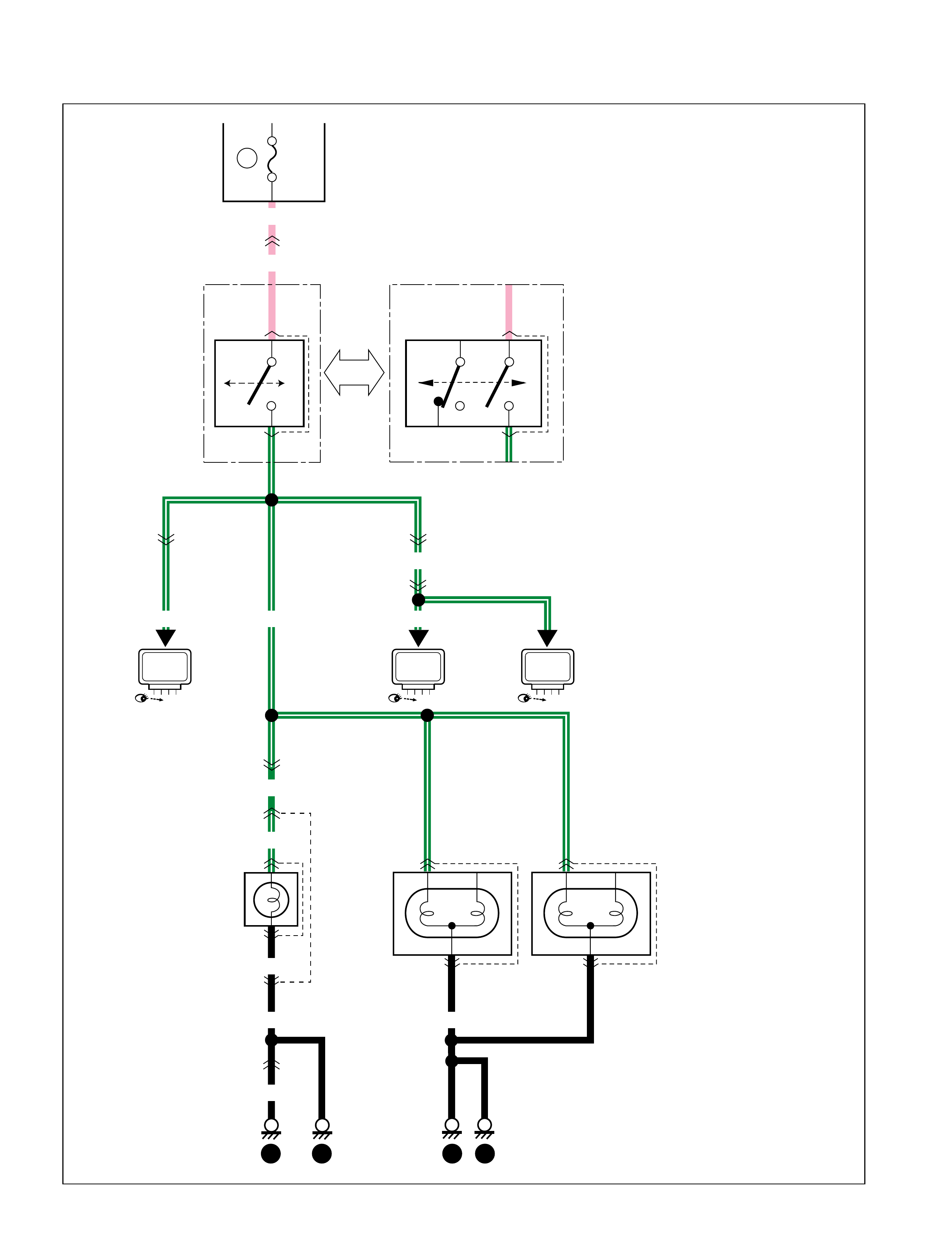
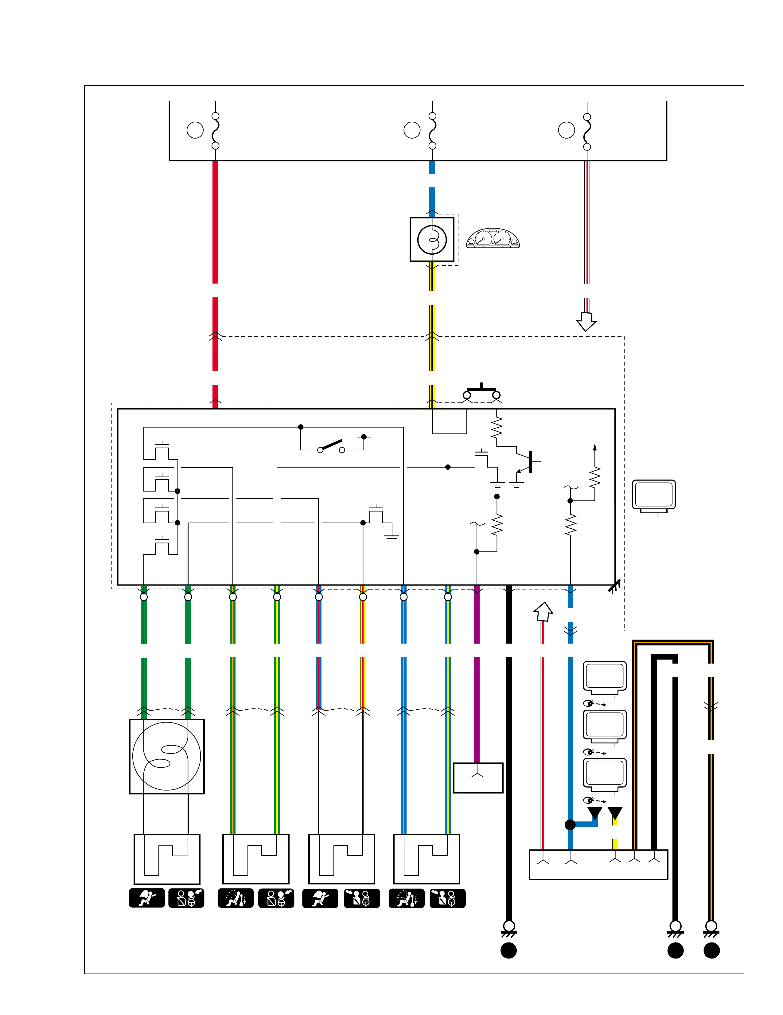
E-1 Heater and air conditioner
17
4123
2
4
10A
G51
G14 8
39 10 5
M
E30 1
2
15
C46
G03
2
G33
E34
25A
HEATER
21
YEL/GRN
RED/BLKGRN/BLK
LT GRN
LT GRN
1
E36
G35
E31
10 1
2
GRN/BLK
PNK
PNK
PNK/BLU
PNK/BLU
BLK/RED
BLK/RED
RED
RED
C53
2
1
Fuse box
Heater resistor
Heater fan
motor
13 15
15 10A BACK
20 11
Dual cut
switch
Blower fan & A/C
switch
A/C switch
DEF switch
TAIL
OFF HEAD
G26
TAIL
6
7
G49
3
4
RED/BLU
ILL controller
BLK
ORNPPL/RED
RED/YEL
WHT
"A-6"
EVAP thermistor
"A-6"
"A-6"
ECM
"A-6"
ECM
ECM
"A-6"
ECM
99512-70H10-GHE.book Page 34 Friday, September 26, 2003 3:16 PM
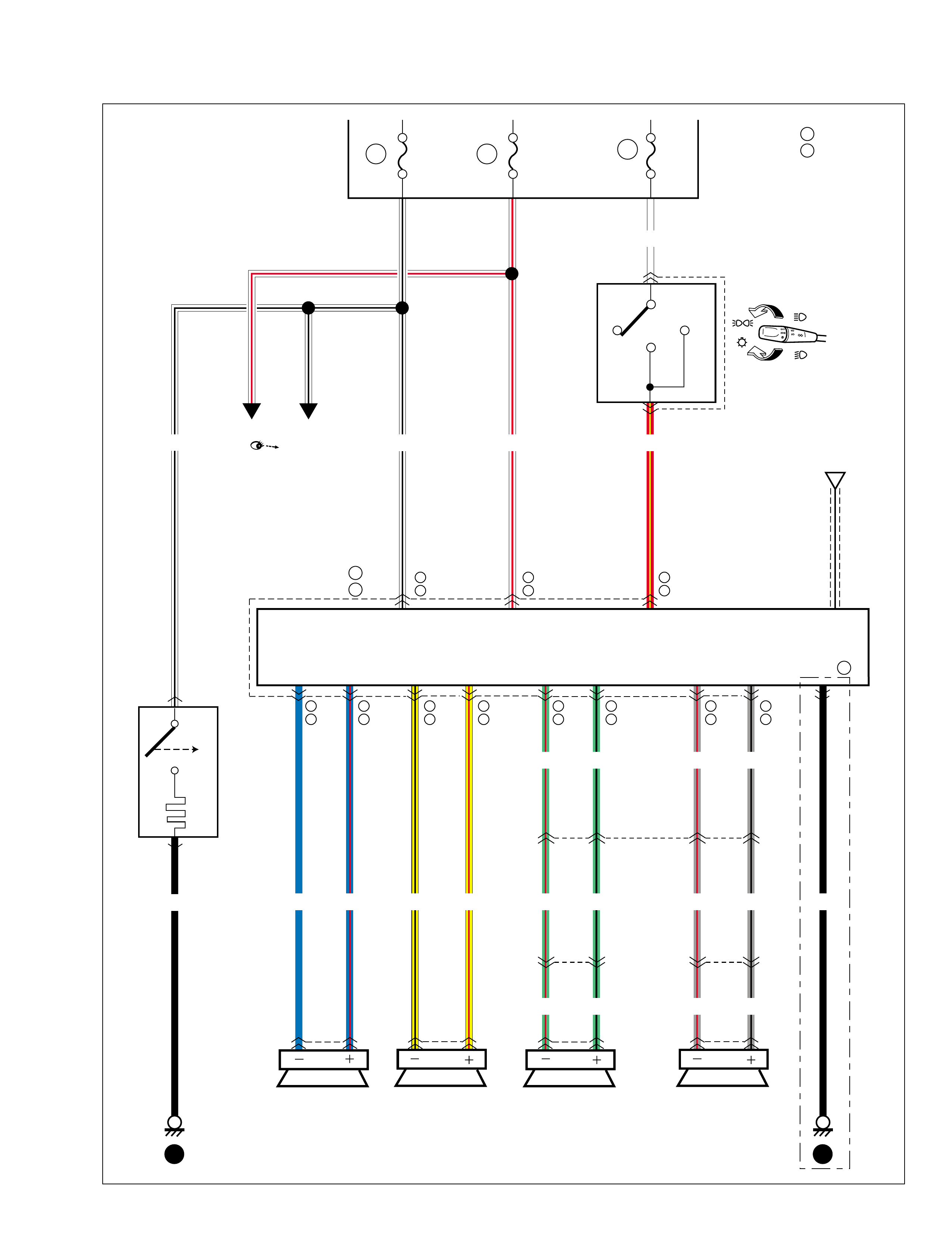
F-1 Radio
G09
G98
G23
G05
8
2
12 12
15A CIGAR 15A RADIO.
DOME
WHT/RED RED/YEL
YEL/REDYEL/BLKBLU/REDBLU
K05
K07 12 12
GRY/BLKGRY/REDLT GRN/RED
LT GRN/RED GRY/REDLT GRN/BLK GRY/BLK
GRY/RED GRY/BLKLT GRN/RED
LT GRN/BLK
LT GRN/BLK
7
G38
L28 17
12 12
L26
K06 L24
K04
8 18
23 16
Fuse box
Front
(L) (R) Rear
(L) (R)
Antenna
Radio
10A
TAIL
OFF
HEAD
G26
TAIL
15
6
7
WHT
Multi information display
"F-2"
WHT/BLK
WHT/BLK
BLK
G16
G17 1
1
PUSH
Cigar lighter
14 15
A Type 1&2
Type 3
B
B
A
B
A
B
10
1
A
B
9
9
A
B
11
13
A
B
4
3
A
B
12
14
A
B
5
4
A
B
1
5
A
B
6
15
A
B
2
6
A
B
BLK
117
16
A
B
99512-70H10-GHE.book Page 35 Friday, September 26, 2003 3:16 PM
F-2 Multi information display
G15 10 2 4 1 3
5
15A CIGAR
15A RADIO.
DOME
WIPER.
WASHER 23
15A
21 16
14
Fuse box
PPL
BLK
10A
TAIL
OFF
HEAD
G26
TAIL
15
6
7
WHT
5
PPL
BLK/RED
1
C20
2
3
4
C46
G03
Vehicle speed
sensor
Relay
Radio
Multi information display
"A-6"
"F-1"
WHT/BLKRED/YEL WHT/RED
YEL
BLK/ORN
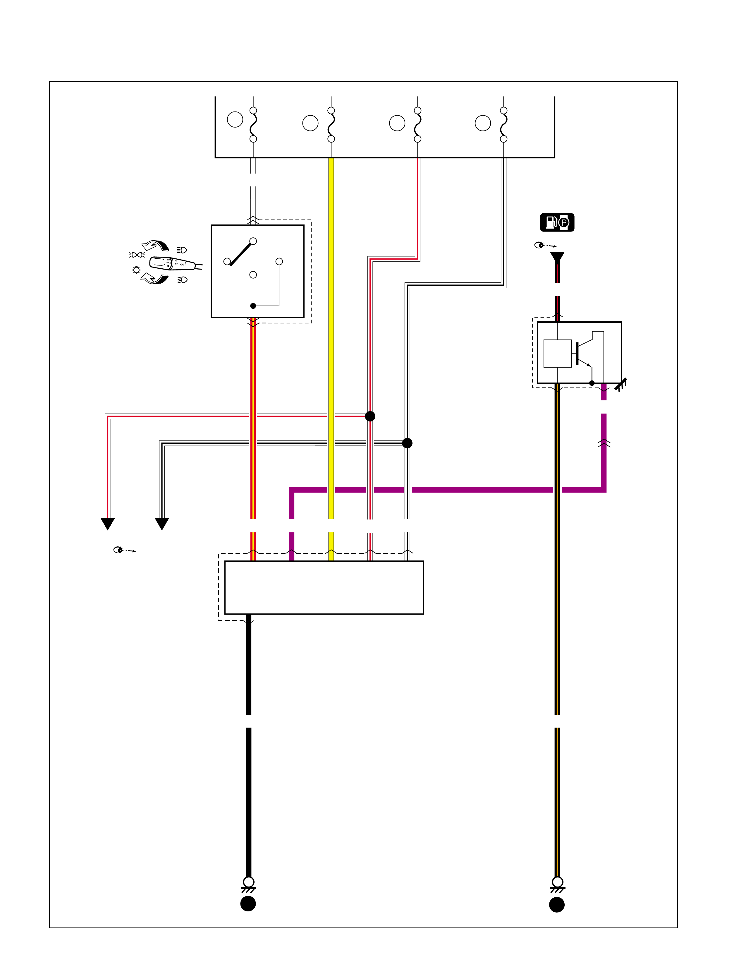
99512-70H10-GHE.book Page 36 Friday, September 26, 2003 3:16 PM
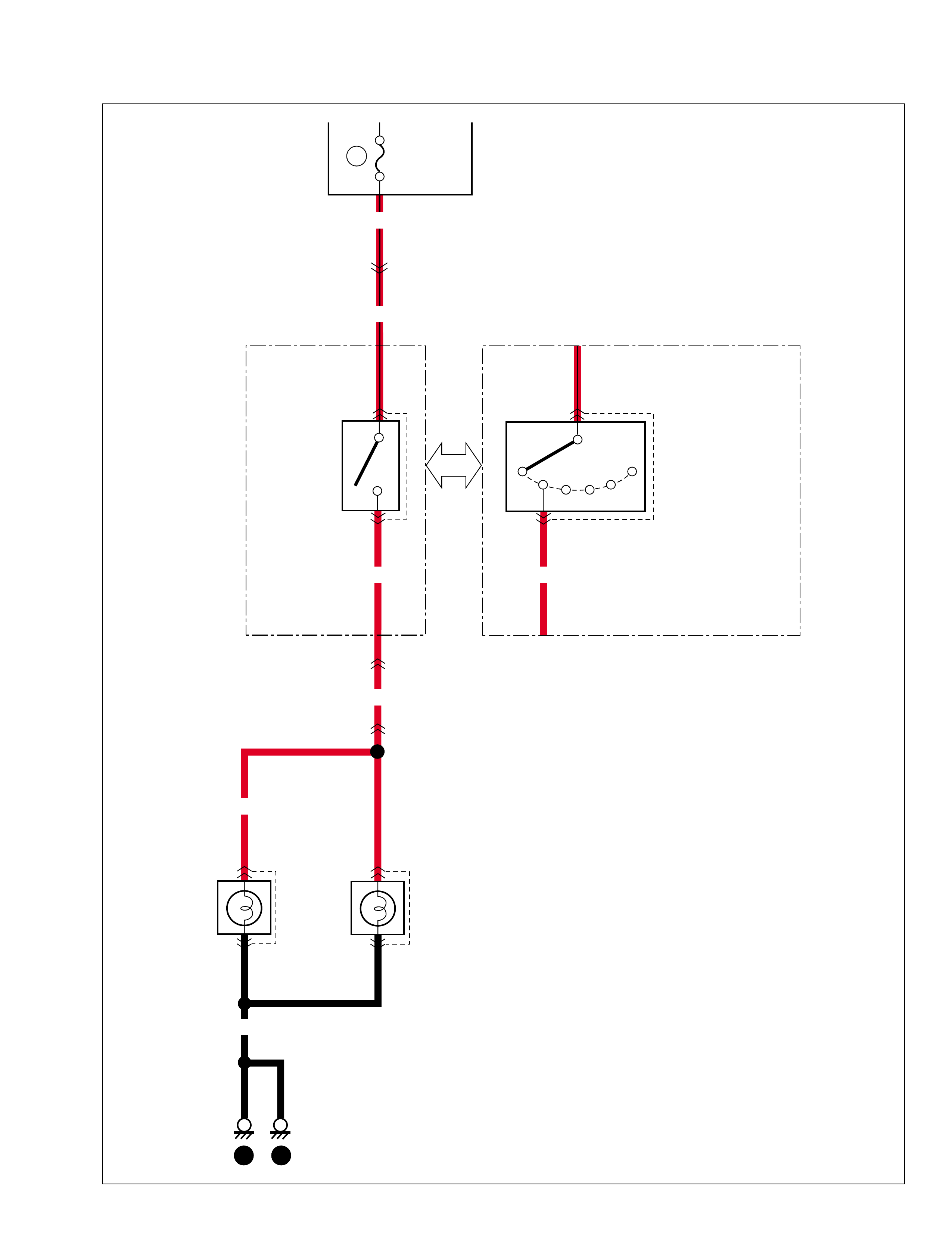
F-4 Warning buzzer
G31
L10
Warning buzzer controller
(In combination meter)
Front door
switch (R)
Diode #2
OPEN
CLOSE
G21 G22
8
1
16
10
7
2
2
1
BLK/YEL
BLK/YEL
BLU/YEL
WHT/RED
BLU
RED/YEL
G20 8
RED
RED
18
G37
L07
16
C46
G03
10A METER RADIO.
DOME
15A
BLK
26 16
13 15
10A
TAIL
OFF
HEAD
G26
Fuse box
TAIL
15
6
7
WHT
Transmission range
sensor
"D-7"
"G-1"
99512-70H10-GHE.book Page 37 Friday, September 26, 2003 3:16 PM
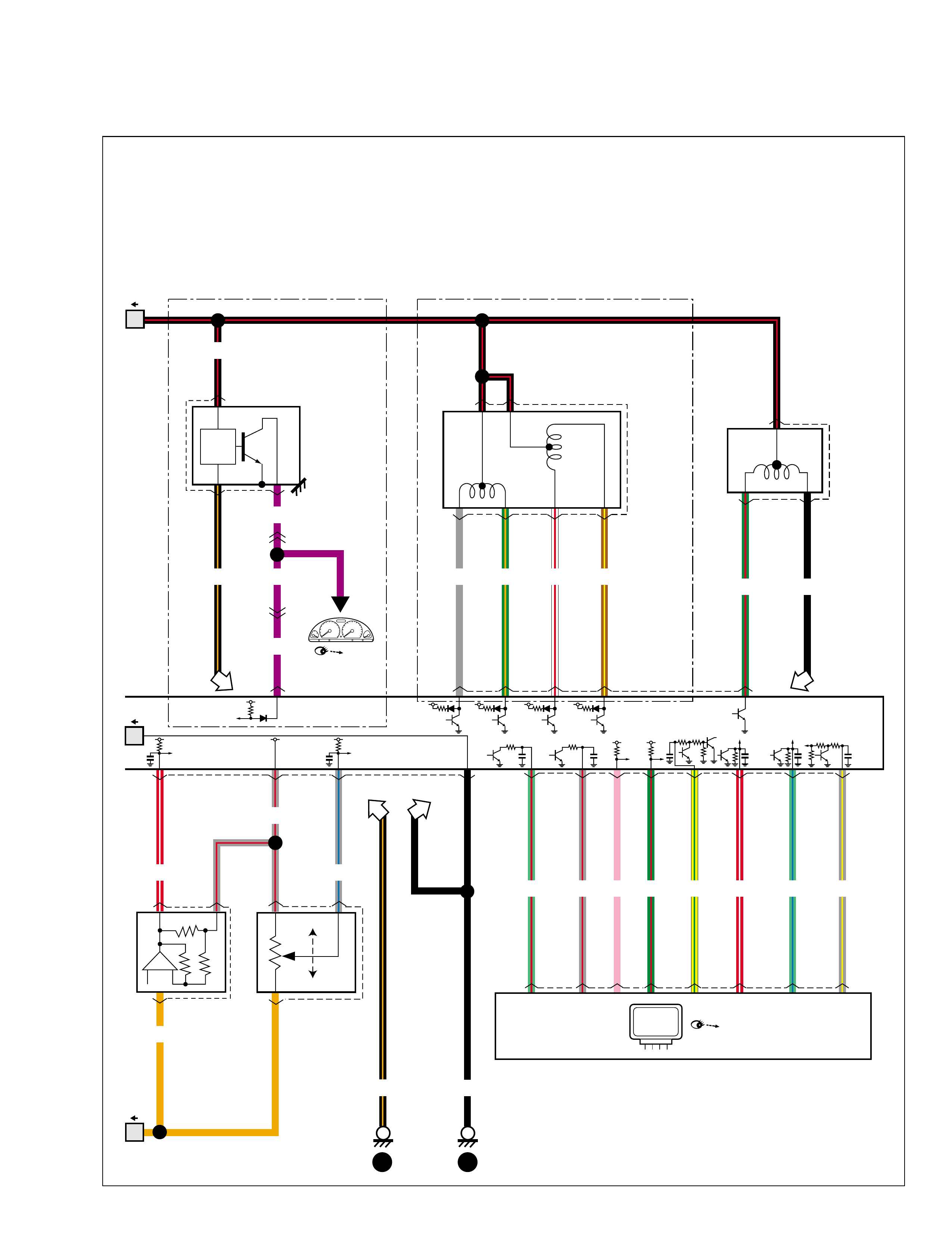
G-1 A/T control system
C43 G99G99
20218912
C43 G99
6
327
985362
PRND2L
C15
RED/BLK
RED/BLK
BLU/WHT
BLU/WHT
10
RED/BLU
28
PPL
GRN/YEL
GRN/YEL
GRN
GRN
GRN/ORN
GRN/ORN
ORN
ORN
RED
RED
BACK
10A
RADIO.
DOME
15A
G19 716945
G07 24
PPL/YEL WHT/RED
BLU
G03
C46 14
BLK
BLK
1
4
L08 3
6
O/D
OFF
SHIFT
LOCK
SOLENOID
STEP
RELEASE
13
ORN
9
G37
L07
G38
L28 1C45
G04 2
RED/BLU PPL/YEL
WHT/RED
GRN/YEL
L04
9
G03
C46
17
C45
G04 16
C46
G03 16
C45
G04 15 14 13
RED/BLU
17
G03
C46
YEL
BLK/ORN
BLK/ORN
2016
Fuse box
7
BLK
Brake light
switch
19 13 15 14 5
Data link connector
Diagnosis connector #2
Back-up light
12V
Transmission
range sensor
A/T shift lever
"A-6"
"D-10"
"A-6"
"A-6"
"C-1"
"G-3"
"C-3"
P/S
Cont.M
ECM
1
1
WHT/RED
412V
12V
TCM
ECM
ECM
For L04:See the wire
colors to identify the
terminals.There are
some kinds of connector
and terminal layout.
99512-70H10-GHE.book Page 38 Friday, September 26, 2003 3:16 PM
19 9
Fuse box Main fuse
36
20
4
16
G02
GRN/WHT
GRN/WHT
11
G03
C46
411
G04
C45 8
15
C99 C43 C43 G99
24
G99
7
L07
G37
22
2
LT GRN/BLK
11
3
RED/WHT
14
4
YEL/GRN
23
5
GRY/YEL
12
6
GRN/RED
18
12
PNK
7
17
GRY/RED
6
15
LT GRN/RED
YEL/BLK
GRN/WHT
BRN
G99C43
C12 2105
20A15A
IG.
METER
C04 24
13
BLK/WHT YEL/GRN
BLK
BLK/WHT
BLK WHT BLK
5 17
15 19
C52 21
BRN
3
BLK/YEL
10
WHT/RED
4
12
WHT/BLU
9
9
WHT/BLK
3
11
BRN/YEL
8
8
LT GRN/RED
1
5
BLU/RED
6
14
GRY
Brake light
switch
Shift
solenoid
#1
Timing
sorenoid
Shift
solenoid
#2
Lock-up
solenoid Pressure
control
solenoid
AT fluid
temperature
sensor
Input shaft speed
sensor
12V12V 12V 12V
5V
5V 12V 12V
2.5V
A/T
A/T relay
WHT BLK
BLK
"A-6"
"C-1" "D-9"
3
C14
2
1
4A/T
speed
sensor
BLK YEL
YEL
3
C45
G04
2 3
32
12V12V12V12V12V 4
ECM
TCM
ECM
"A-6"
ECM
13
G03
C46
99512-70H10-GHE.book Page 39 Friday, September 26, 2003 3:16 PM
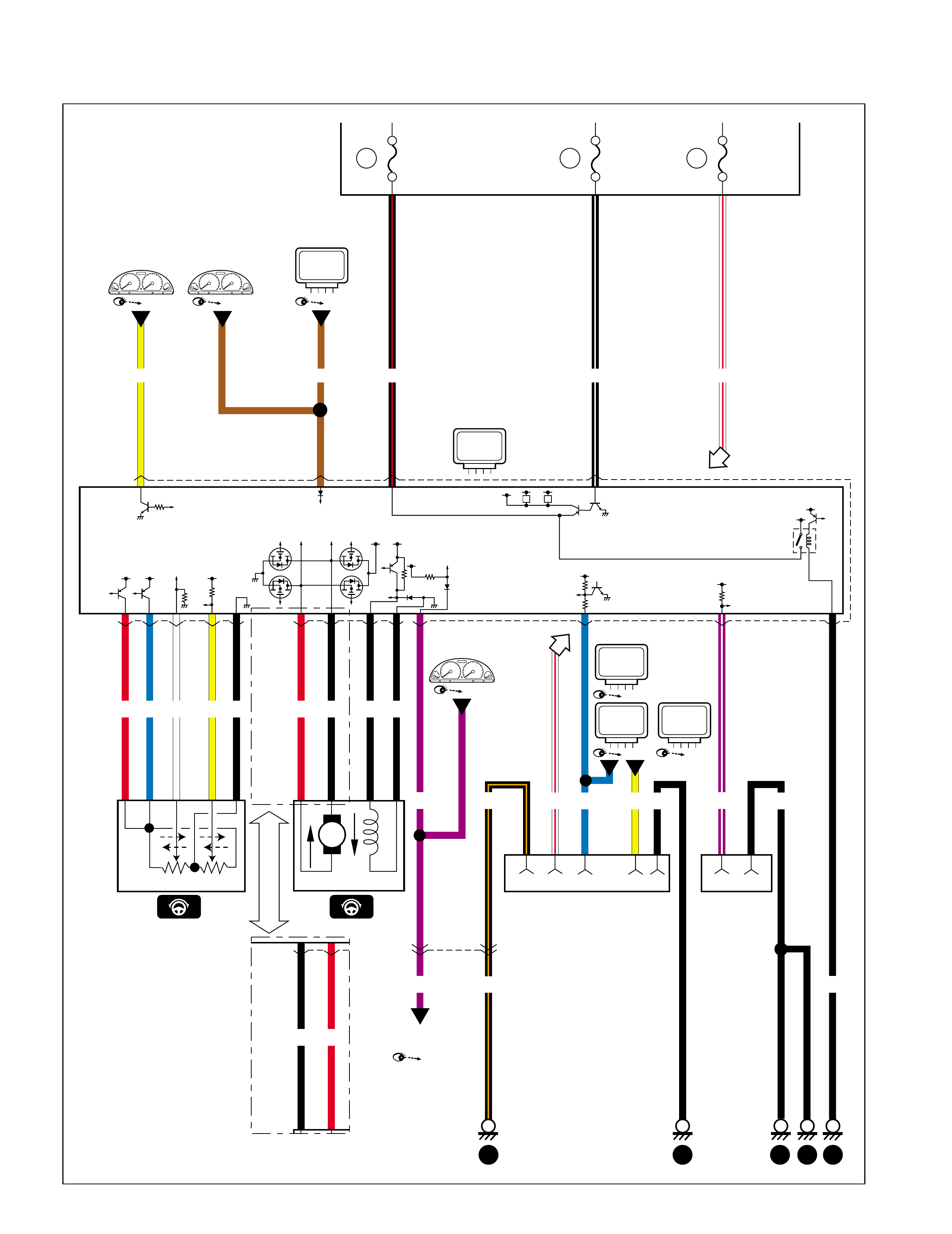
G-3 Power steering
65
7432134521 4
34
4716
18
G24
G24-2G24-1
G07G19
BLK/RED BLK/WHT WHT/RED
30A P/S 15A IG 15A
RADIO.
DOME
9
PPL/WHTPPL BLK
PPL
2
4
G03
C46 14
BRNYEL
MAIN SUB
BLK RED BLK
BLK RED
YELWHTBLURED
M
R
L
BLK BLK
3
RR LL
BLK
BLKBLU YEL
WHT/RED
5
BLK/ORN
BLK/ORN
Fuse box 24 19 16
5 14 13 15 17
Torque sensor
Vehicle speed
sensor
Data link connector Diagnosis
connector #2
"C-3" "C-1" "A-6"
"C-1"
"C-1"
"A-6"
1
1
P/S
Cont.M
ECM
21
G24-2
ECM
"A-3"
ICM
"G-5"
ABS
Cont.M
Motor & clutch
99512-70H10-GHE.book Page 40 Friday, September 26, 2003 3:16 PM
G-4 Air-bag control system
Fuse box
2618 16
51423
2
16
L48
G19 74
RED
RED
GRN/ORN GRN/YEL PPL BLK BLU
BLU
1
G39
L45
14
G03
C46
3
2
10A METER
2
10 9 12 11
BLU/RED YEL/RED
GRN/RED GRN
78
BLU/ORN BLU/YEL
5615 14
17
4
L51
15A AIRBAG 15A
RADIO.
DOME
G22 10
2
AIR BAG
BLU
YEL/BLK WHT/RED
YEL/BLK
BLK
59
BLK/ORN
BLK/ORN
12
L46 12
L49 12
L47 12
L50
WHT/RED
Contact
coil
Connection
detection pin
YEL
Data link connector
Diagnosis
connector #3
A/B
Cont.M
ECM
"A-6"
P/S
Cont.M
"G-3"
ABS
Cont.M
"G-5"
1
1
99512-70H10-GHE.book Page 41 Friday, September 26, 2003 3:16 PM
G-5 Anti-lock brake system
E14
11
L31
L12 2 1
L05
E33 6 5
2
L05
E33
12
WHT/BLUGRN/ORN ORN BLK/ORN
ORN BLK/ORN
GRN/WHT
ORN BLK/ORN GRN/WHT
11
G35
E36
RED/BLU
RED/BLU
2
G34
E35
PNK/BLU
PNK/BLU
10A ABS 15A
RADIO.
DOME
1
G34
E35 14
G37
L07
3
L12
L31
GRN/ORN WHT/RED
1
50A
2
GRN/ORN
GRN/ORN
L32 3
IFR
OFR
IFR
OFL
IRR
ORR
IRF
ORF
M
1
12V
22 16 4
Fuse box
Main fuse
Solenoid
valve relay Motor relay
12V
(ABS indicator) Brake light
switch
G Sensor
(4WD)
12V
5V
"D-9""C-3""C-3" (EBD indicator)
ABS
Cont.M
A Type 1&2
Type 3
B
E19
E41
A
B18
7
AA13
A
B25
14
A
B23
1
A
B14
17
A
B10
23
A
B2
3
A
B
99512-70H10-GHE.book Page 42 Friday, September 26, 2003 3:16 PM
E09 21
E18 21
L15 21
L18 21
WHT/BLKWHTRED/BLKRED LT GRN/BLKLT GRN/RED
LT GRN/BLKLT GRN/RED
YEL BRN
YEL BRN
PNK
PNK
BLK
4
L05
E33 10 3 9
4
6
G07
BLU
457169
G19
6
E36
G35
14
G03
C46
7
BLU BLK
2
BLK
1
12 13 15 14 5
WHT/RED BLK/ORN
BLK/ORN
Wheel speed sensor (FL) Wheel speed sensor (FR) Wheel speed sensor (RL) Wheel speed sensor (RR)
Diagnosis connector #2 Data link connector
5V 5V 5V
12V
12V
5V
ABS
Cont.M
ECM
"A-6"
P/S
Cont.M
"G-3"
YEL
E19
E41
A
B15
21
A
B
24
13
A
B
22
26
A
B
12
20
A
B
21
5
A
B
16
22
A
B
3
19
A
B
4
18
A
B
19
15
A
B
20
16
A
B
7
25
A
B
6
24
A
B
99512-70H10-GHE.book Page 43 Friday, September 26, 2003 3:16 PM

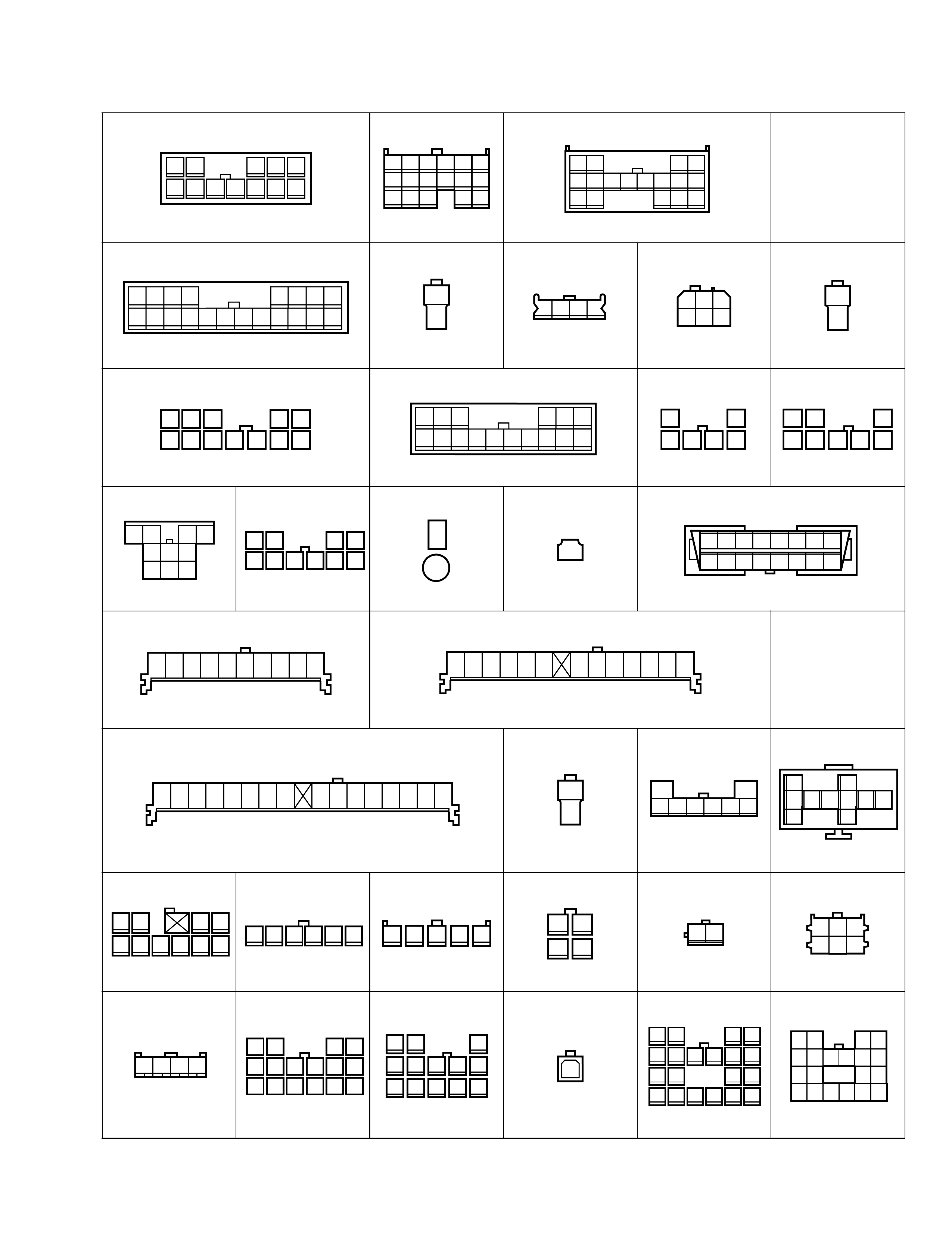
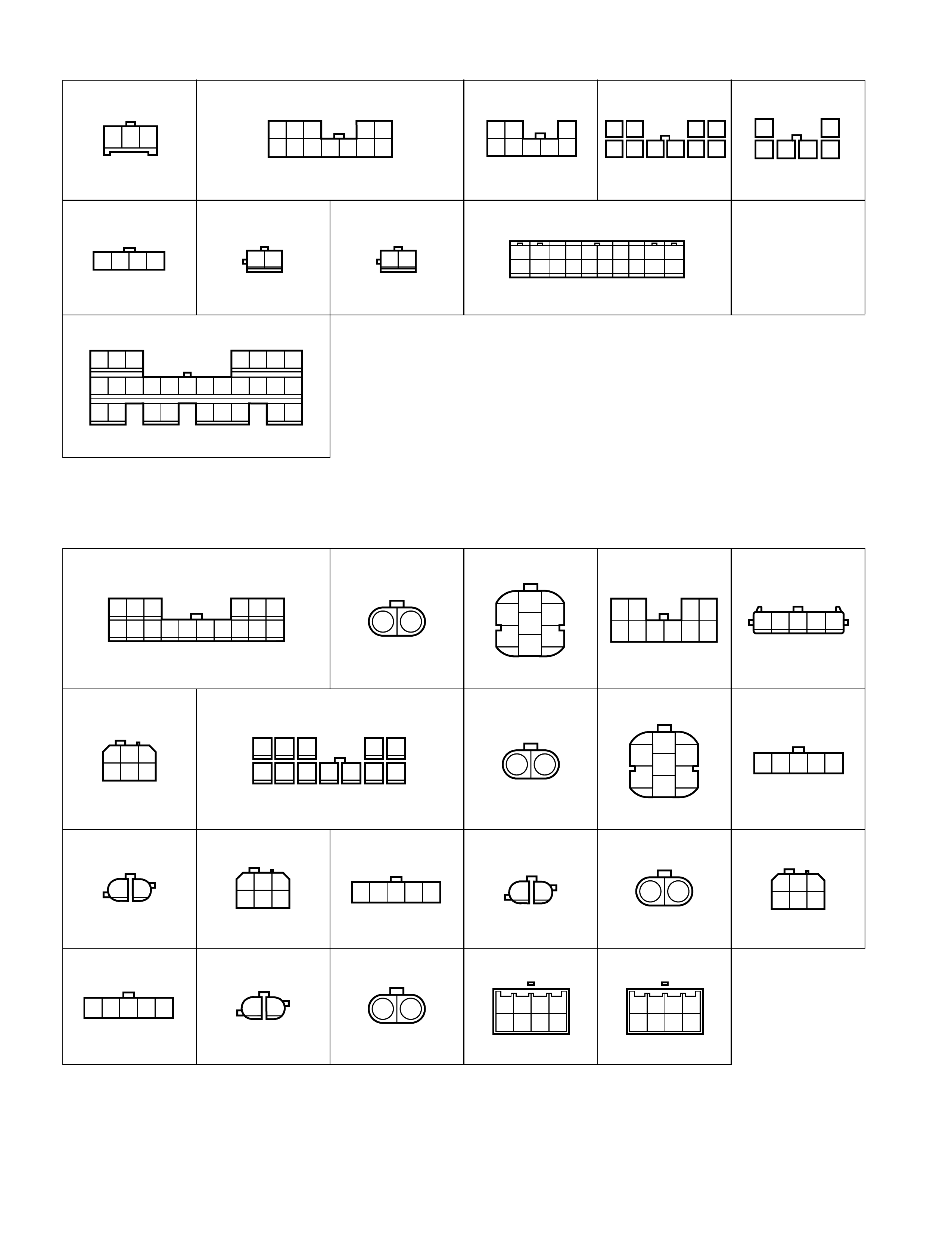
Connector list
C Connector
C01 C02 C03 C04 C05 C06
C08 C09 C10 C11 (TO E10) C12
C14 C15 C17 C18 C19
C20 C21 C22 C23 C24 C25
C26 C27 C28 C29 C30 C31
C32 C34 C35 C36 C37 C38
C39 C40 C41 C42
C43 C45 (TO G04) C46 (T O G03)
1113
4
123
4
123
4
12
3
4
123
4
123
4
1221 12
6
5
10
7
4
9
3
8
123 12
56
3
97 8
4
10 12123 123
123
12
3
23112 12 12
12 123 12 123 11
1
3
2
41123 123 11
1123 17 18 2019 21 22 23 24
12 43567
89 1110 12 13 14 15 16 1
10 11 12 13 14 15 16 17 18 19 20 21
22 23 24 25 26 29 3027 28 31
2 3456789
12 34
5678910111213
14 15 16 17 18 19 20
1 2 3 4
9 10 11 12 5 6 7 8
17 18 19 2013 14 15 16
1 2
5 6 7
13 14
3 4
11 12
16 1715 8 9 10
99512-70 H 10-G H E.book Page 1 Friday, Sept ember 26, 2003 3:16 PM
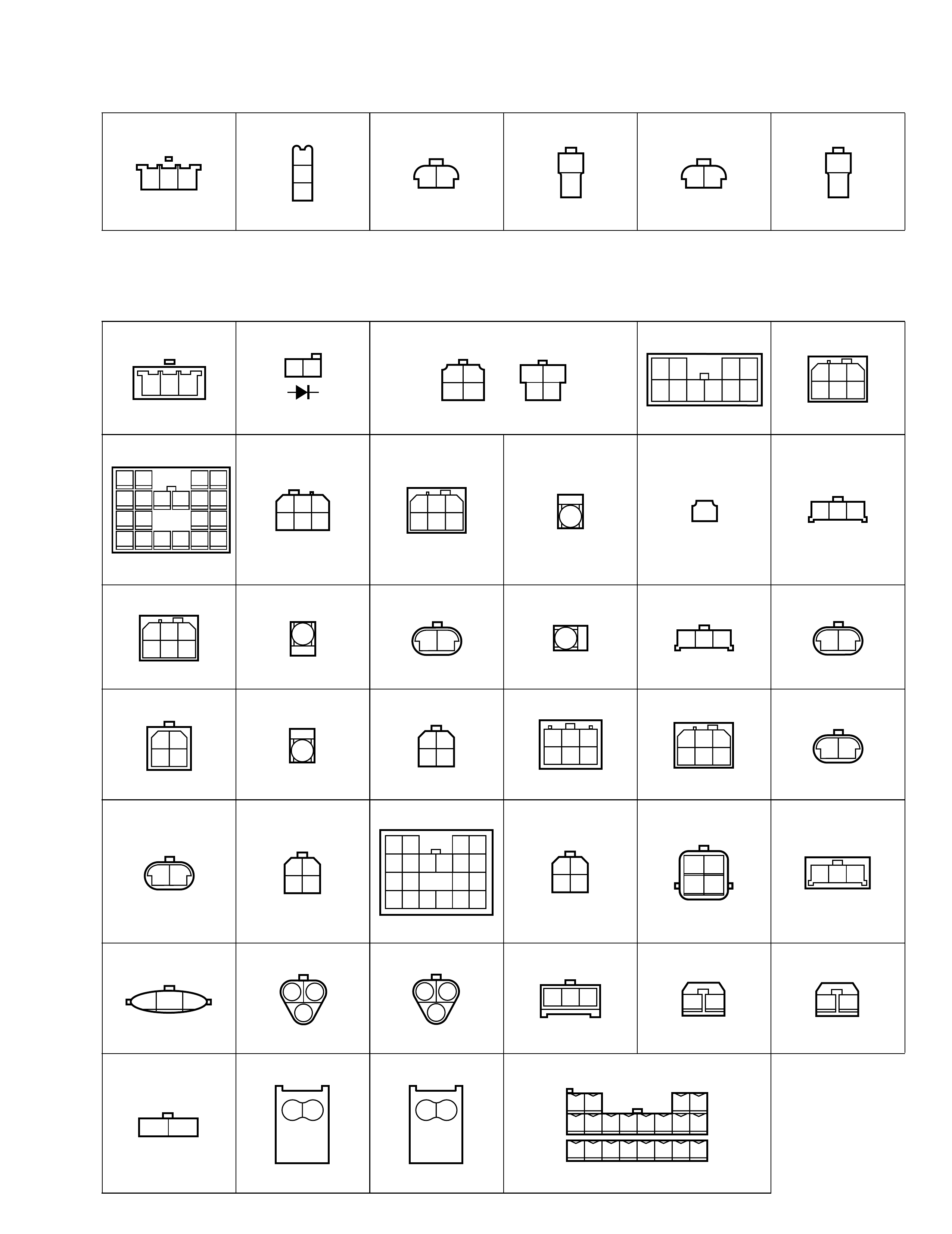
E Connector
C50 C51 C52 C53 C54
123
456 12 12 12 123
465
E01 E03 E04 E05 E06 E07
E09 E10 (TO C11) E11 E12 E13 E14
E15 E16 E17 E18 E19
E20 E21 E22 E23 E24 E25
E26 E27 E28 E30 E31 E33 (TO L05)
E34 (TO G33) E35 (TO G34) E36 (TO G35) E37 E38 E39
E40 E41
211
2121
23 12
34 345
1
28910
6
7
2112 1221 11
1212
34 2
121
1234567
8 9 10 11 12 13 14 22 23
24 25
15 16 17 18 19 20 21
12 21121
23 1
21
2
1
212
34 121
212
34
1234
5678910
1243 111213141516 5678910 1234 3
8
13
2 1
5 4
10 9
7 6
12 11 1121
112 3 4 5 6 7 8 9 10 11 12 13
14 15 16 17 18 19 20 21 22 23 24 25 26
99512-70 H 10-G H E.book Page 2 Friday, Sept ember 26, 2003 3:16 PM
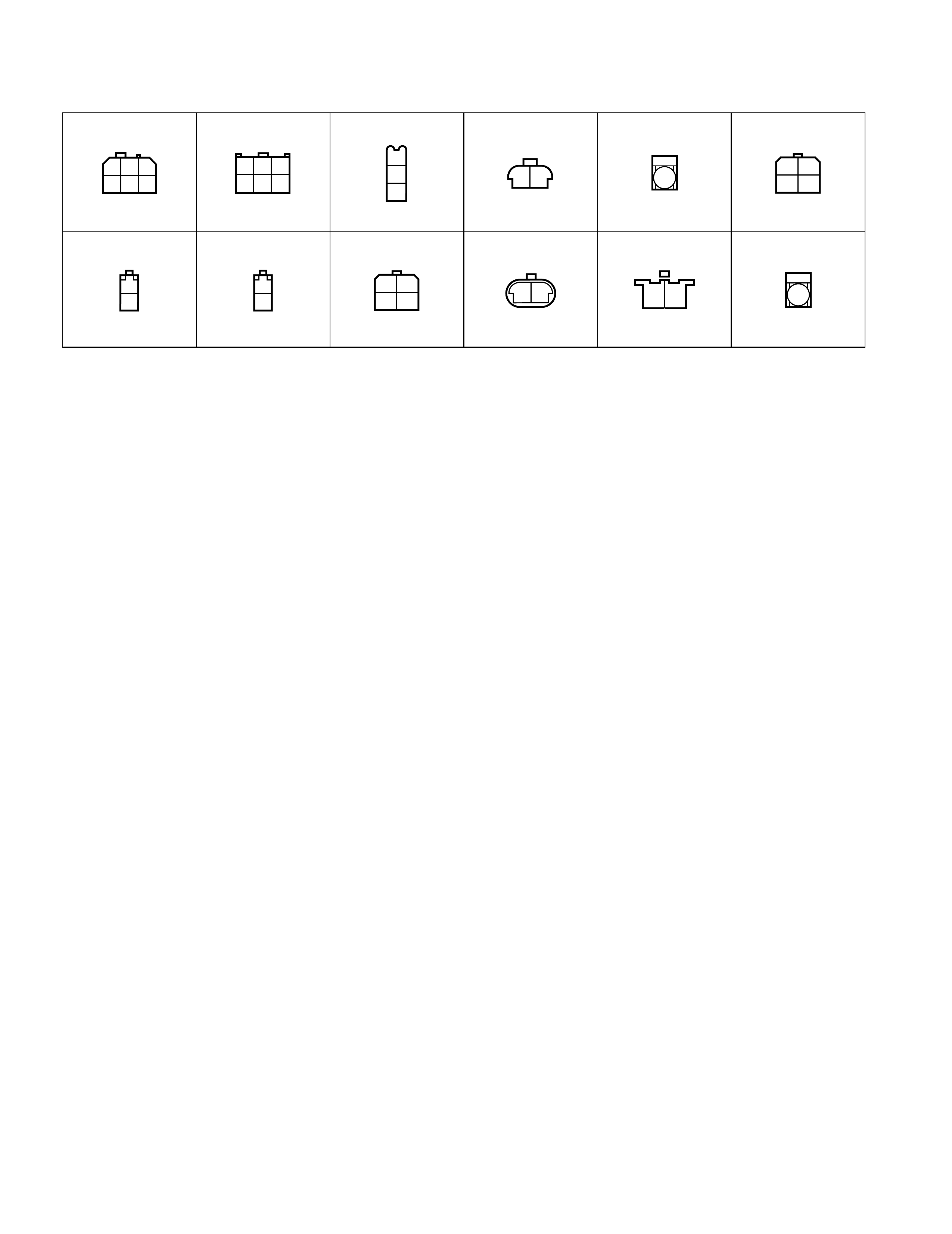
G Connector
G01 (TO J07) G02 G03 (TO C46)
G04 (TO C45) G05 G06 G07 G08
G09 G10 (TO J01) G12 G 13
G14 G15 G16 G17 G19
G20 G21
G22 G23 G24 G25
G26 G27 G28 G29 G31 G32
G33 (TO E34) G34 (TO E35) G35 (TO E36) G36 G37 (TO L07) G38 (TO L28)
5 4
12 11
3 2
8 7
1
610 9
123456
789101112
13 14 15 16 17 12 11 10 9 8 7
17 16
4 3 6
1415
25
13
1
8765 43
16 15 14 13
21
20 19 18 17 12 11 10 9
1
24312 321 645 1
2
1
6
2
7
4
11
5
12
3
8 9 10
654 32
13 101112 1
16 15 14 9 8 7 1
3
2
64 5
1
4
2
5
3
86 7
12 34
567
8910
1
52
63
94
107 8 1112345678
910111213141516
12345678910 123456 78910111213
1 2 3 4 5 6 7 8 910111213141516 1
2
12
843675345
1
28910
6
7
1098765
4321 1 2 3 4 5 6 1 2 3 4 5 1 2
3 4 21 3
21 654
4312
161514131211 1098765 4321 1 2
4 5
9 10
3
8
13
6 7
11 12 1
201918171615 1413
87
1211 10965 4321
20191817
1615 1413
8
7
1211 109
65 43
21
99512-70 H 10-G H E.book Page 3 Friday, Sept ember 26, 2003 3:16 PM
J Connector
G39 (TO L45) G40 G42 G44 G46
G49 G50 G51 G98
G99
321 123 45
6 7 8 9 10 1112 12 3
846751
52
63
94
107 8 1
3
2
64 5
4312 21 21 321 1094 5 6 7 8
131211 20191415161718
123 4567
8 9 10 11 12 13 14 15 16 17 18 19
20 21 22 23 24 25 26 27 28
J01 (TO G10) J02 J03 J04 J05
J06 (TO L06) J07 (TO G01) J08 J09 J10
J11 J12 (TO L09) J13 J14 J15 J16 (TO L13)
J17 J18 J19 J21 J22
123 45
10 131211 6
789 141516 12 13
4
5
2
6
7
1234
5678910 12345
123
465
1
6
2
7
3
8
4
11
5
129 10 12 13
4
5
2
6
712345
12123
46512345 1212 123
465
12345 1212 4325
1
7684325
1
768
99512-70 H 10-G H E.book Page 4 Friday, Sept ember 26, 2003 3:16 PM
K Connector
L Connector
K01 (TO L01) K03 K04 (TO L24) K05 K06 (TO L26) K07
123
1
3
221 1
221 1
2
L01 (TO K0 1) L02 L03/L04 L05 (TO E33) L06 ( TO J06)
L07 (TO G37) L08 L09 (TO J12) L10 L11 L12 (TO L31)
L13 (TO J16) L14 L15 L16 L17 L18
L19 (TO L29) L20 L21 L22 L23 L24 (TO K04)
L26 (TO K06) L27 L28 (TO G38) L29 (TO L19) L3 0 L31 (TO L12)
L32 L43 L44 L45 (TO G39) L46 L47
L48 L49 L50 L51
321 21
()
12 or
34 12
43 4321
10 98765 123 465
151617181920 1112
78
1314 56910 1234
123
465123 465 11123
123 465 11
21123 1
2
21
43 112
34 1
23 456 123 465 1
2
1
212
34 1516
1718
1920 1112
78
1314 56
910 1234
12
34 2
1
34
2
1
34321
2312
13
2
13123 1 2 1 2
1212 12 12 34
56789101112
13 14 15 16 17 18 19 20
99512-70 H 10-G H E.book Page 5 Friday, Sept ember 26, 2003 3:16 PM
O Connector
O01 (TO L23) O02 (TO L22) O03 O04 (TO O10) O05 O06
O07 O08 O09 O10 (TO O04) O11 O12
123
465123
465
1
3
221 112
34
1
21
212
34 1
221 1
99512-70 H 10-G H E.book Page 6 Friday, Sept ember 26, 2003 3:16 PM