
SECTION 8B - AUDIO SYSTEM
1. GENERAL DESCRIPTION
2. ON-VEHICLE SERVICE
2.1 AUDIO UNIT PIN CODE
2.2 AUDIO UNIT
Removal
Disassemble
Installation
2.3 FRONT SPEAKER
Removal
Installation
2.4 REAR SPEAKER
Removal
Installation
2.5 ANTENNA
Removal
Installation
WARNING:
For vehicles equipped with Supplementary Restraint (Airbag) System:
• Service on and around the airbag system components or wiring must be performed only by an
authorised HOLDEN retailer. Refer to AIRBAG SYSTEM COMPONENTS and WIRING LOCATION
VIEW under GENERAL DESCRIPTION in Section 10B AIRBAG SYSTEM in order to confirm
whether you are performing service on or near the airbag system components or wiring. Please
observe all WARNINGS and SERVICE PRECAUTIONS under ON-VEHICLE SERVICE in Section
10B AIRBAG SYSTEM before performing service on or around the air bag system components or
wiring. Failure to follow WARNINGS could result in unintentional activation of the system or
could render the system inoperative. Either of these two conditions may result in severe injury.
• Technical service work must be started at least 90 seconds after the ignition switch is turned to
the “LOCK” position and the negative cable is disconnected from the battery. Otherwise, the sys-
tem may be activated by reserve energy in the Sensing and Diagnostic Module (SDM).
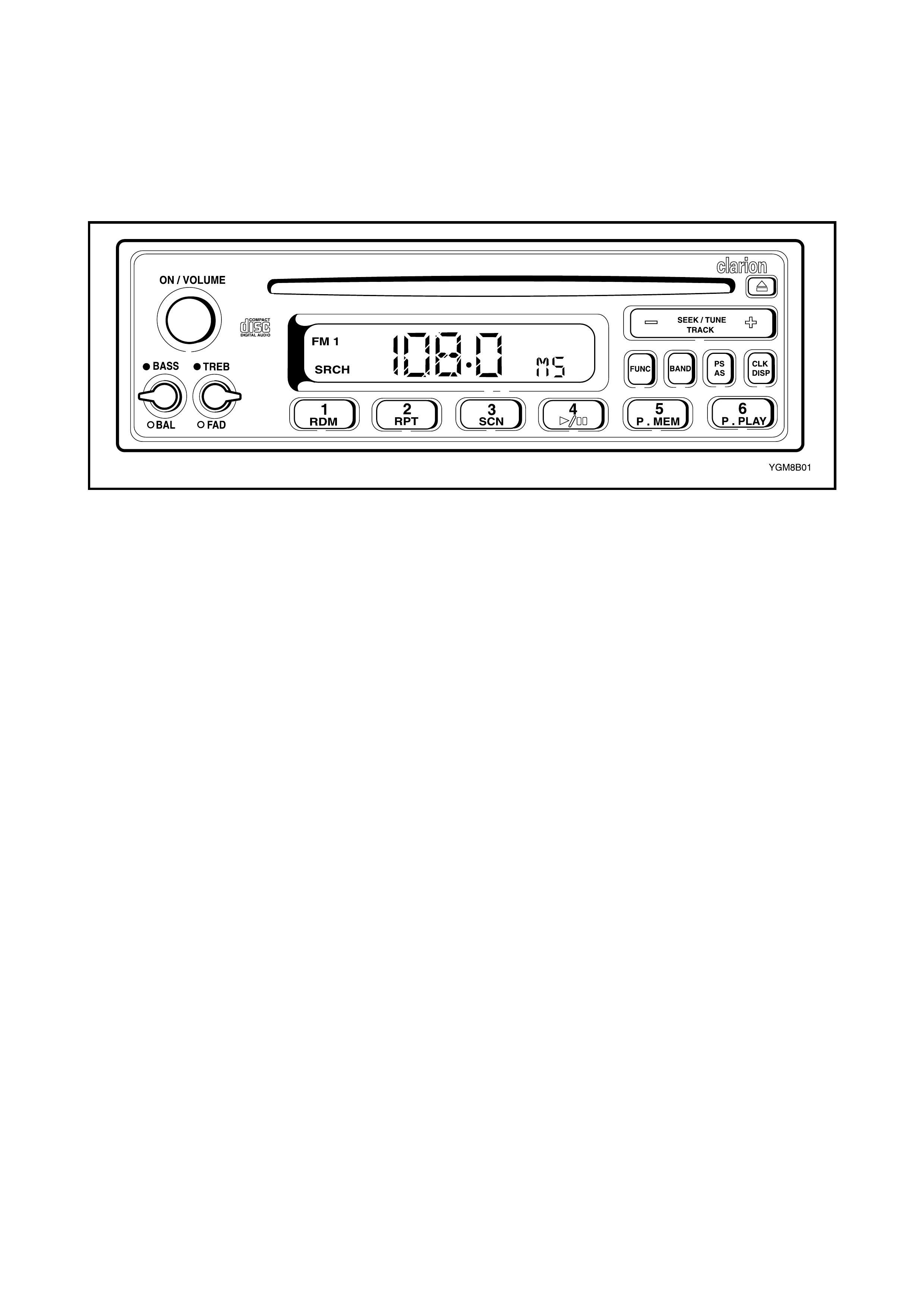
1. GENERAL DESCRIPTION
The aud io system feat ures a singl e disc CD playe r with AM/FM radi o. Four spea kers are in cluded, one each
side of the instrument panel upper and one in each rear body pillar.
For further general information, refer to the audio system operators manual.
2. ON-VEHICLE SERVICE
2.1 AUDIO UNIT PIN CODE
Any ti me the ba ttery voltage supply to the aud io unit is interrupted (batter y discon nection, fus e, etc.) the unit
will require reinstating by entering a personal identification number (PIN) code as follows.
1. Reconnect the battery or reinstate the power supply to the audio system.
2. Obtain the audio unit PIN code from the card provided with the owner’s manual.
3. Turn the ignition switch to ON or ACC position.
4. Switch ON the audio unit be pressing the ON / VOLUME knob.
5. Press and hold the CLK button for at least two seconds until the clock display indicates 0.
6. Press the SEEK / TUNE UP (+) or DOWN (-) button until the correct first number of the PIN is displayed.
7. Briefly press CLK button to set the first number.
8. Repeat Steps 5 and 6 until the remaining numbers are entered.
•If a wrong PIN is entered, the word WRONG will appear in the display. The code can be re-entered using
the above procedure.
•If the correct code is set, the display will return to the radio mode.
2.2 AUDIO UNIT
REMOVAL
1. Disconnect the negative battery cable at the battery.
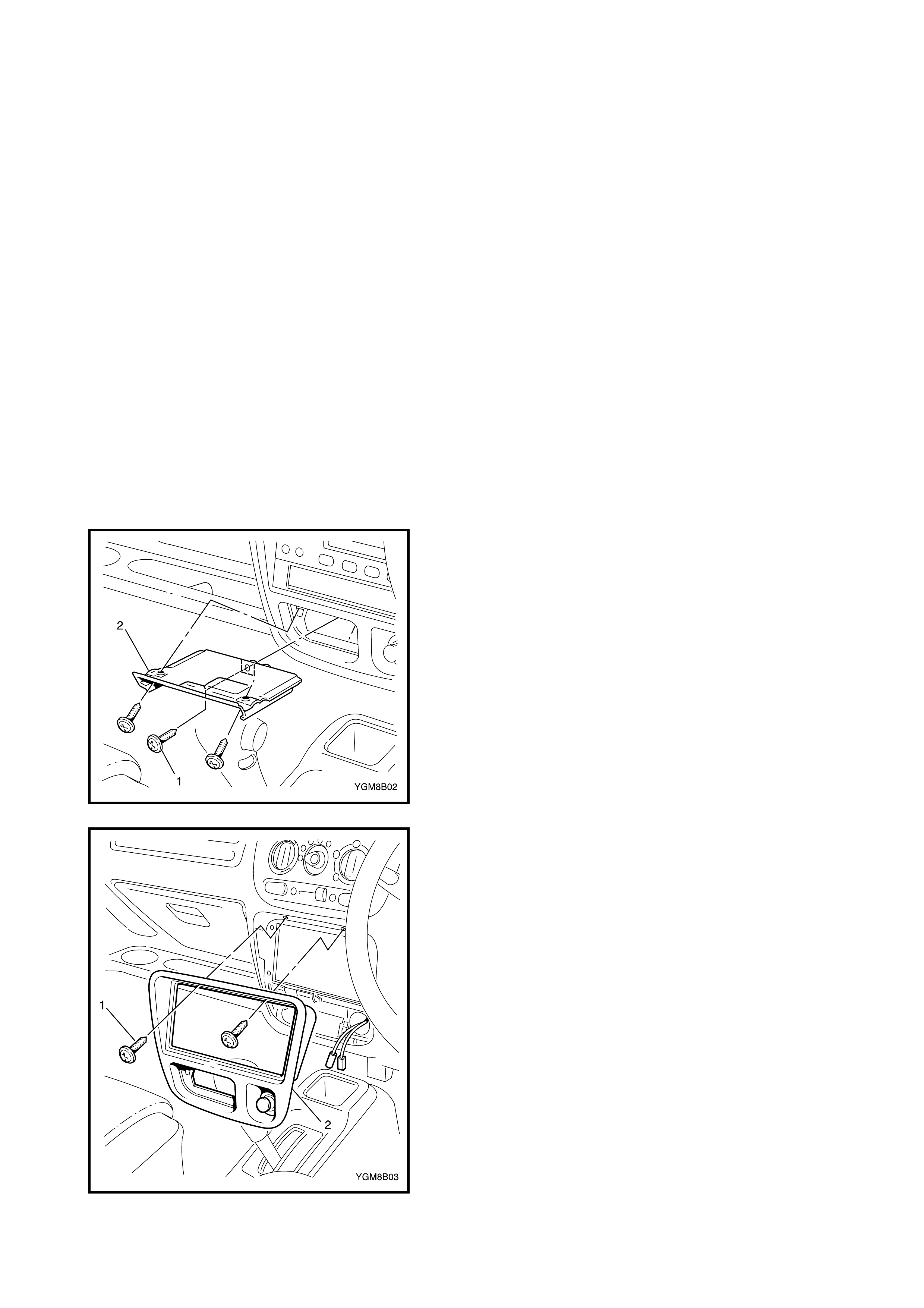
2. Remove the ashtray.
3. Remove the three screws (1) attaching the ashtray
carrier (2) and remove.
4. Remove the two screws (1) attaching the garnish (2)
and carefully prise the garnish from the instrument
panel.
5. Disconnect the cigarette lighter connectors and
remove the garnish.
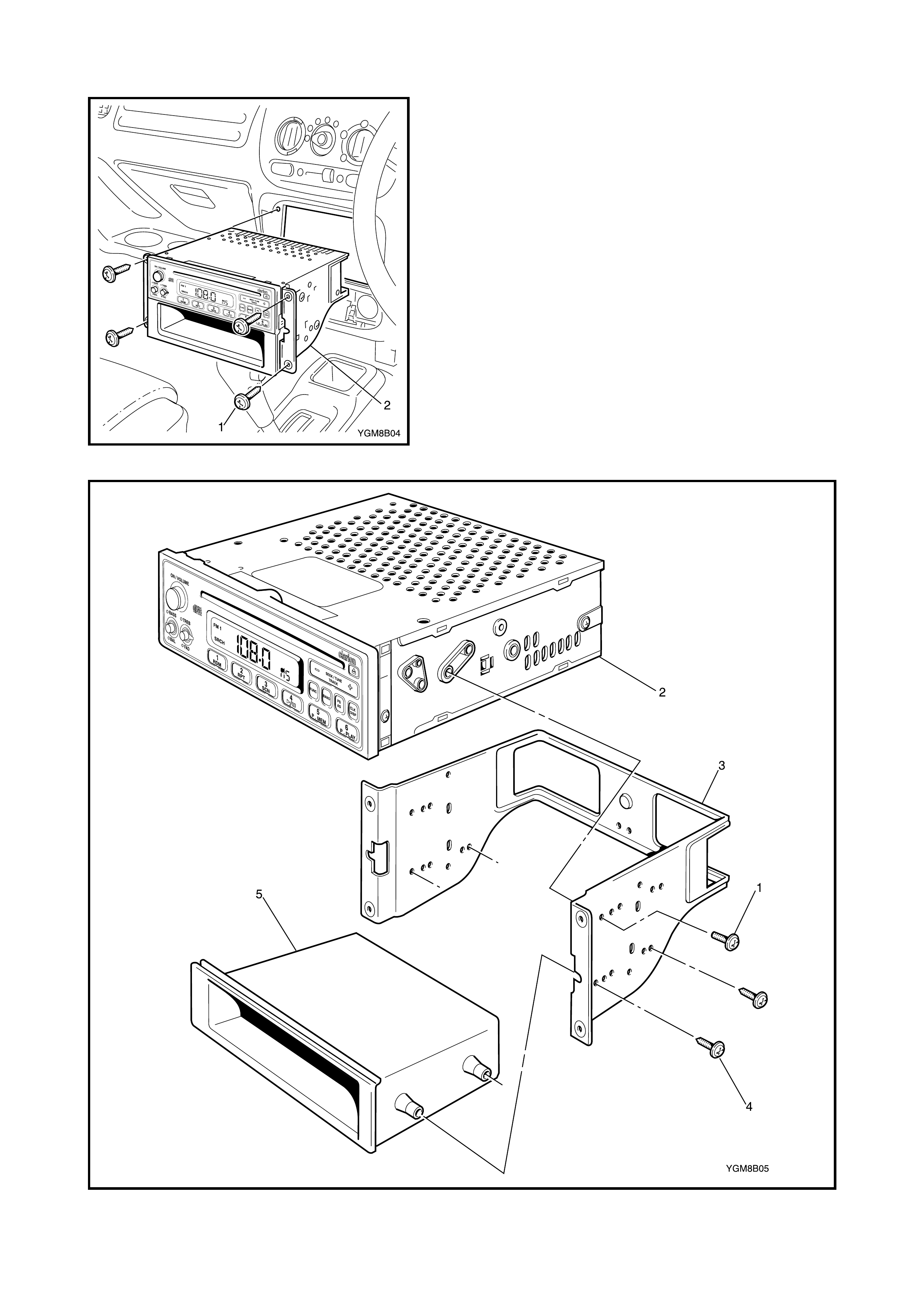
6. Remove the four screws (1) attaching the audio unit
and storage co mpartm ent as se mbly (2 ).
7. Withdraw th e assembly from the in strument panel and
disconnect the wiring and antenna connectors and
remove the assembly.
DISASSEMBLE
Legend
1. Audio unit screw 3. Mounting bracket 5. Storage compartment
2. Audio unit 4. Storage compartment screws
INSTALLATION
1. Install in reverse order of removal. When installation is
complete, reinstate the audio unit by entering the PIN
code, refer to 2.1 AUDIO UNIT PIN CODE in this
Section.
2.3 FRONT SPEAKER
REMOVAL
1. Disconnect the negative battery cable at the battery.
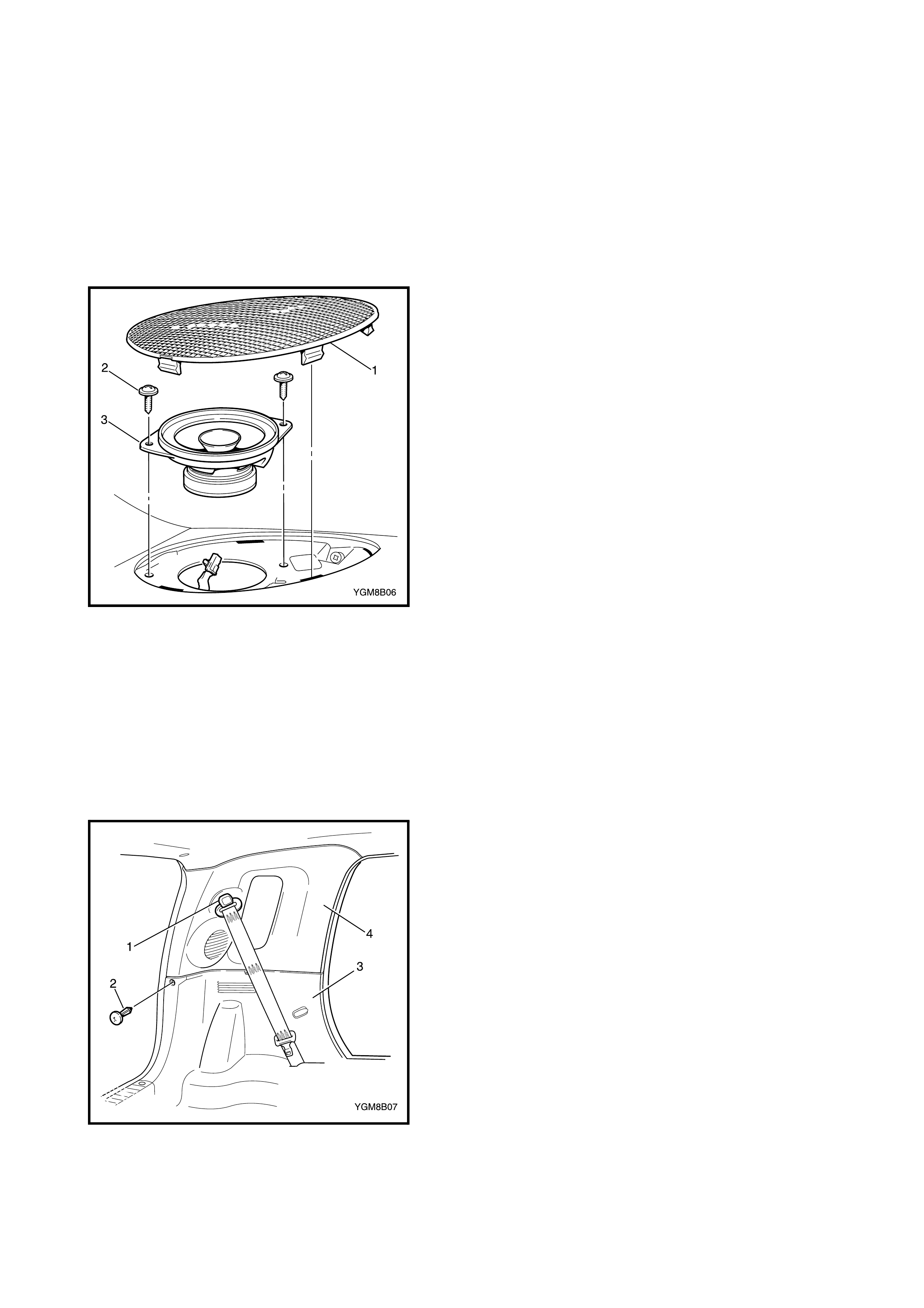
2. Carefully prise the rear edge of the speaker cover at
the notch (1) and remove the cover.
3. Remove the two screws (2) attaching the speaker (3).
4. Lift out the speaker and disconnect the wire connector.
5. Remove the speaker.
INSTALLATION
1. Install in re verse ord er of remo val. Whe n installa tion is
complete, reinstate the audio unit by entering the PIN
code, refer to 2.1 AUDIO UNIT PIN CODE in this
Section.
2.4 REAR SPEAKER
REMOVAL
1. Disconnect the negative battery cable at the battery.
2. Remove the rear seatbelt upper anchor bolt (1).
3. Remove the retainer (2) and remove the upper part of
the lower rear side trim (3).
4. Remove the upper rear side trim. (4)
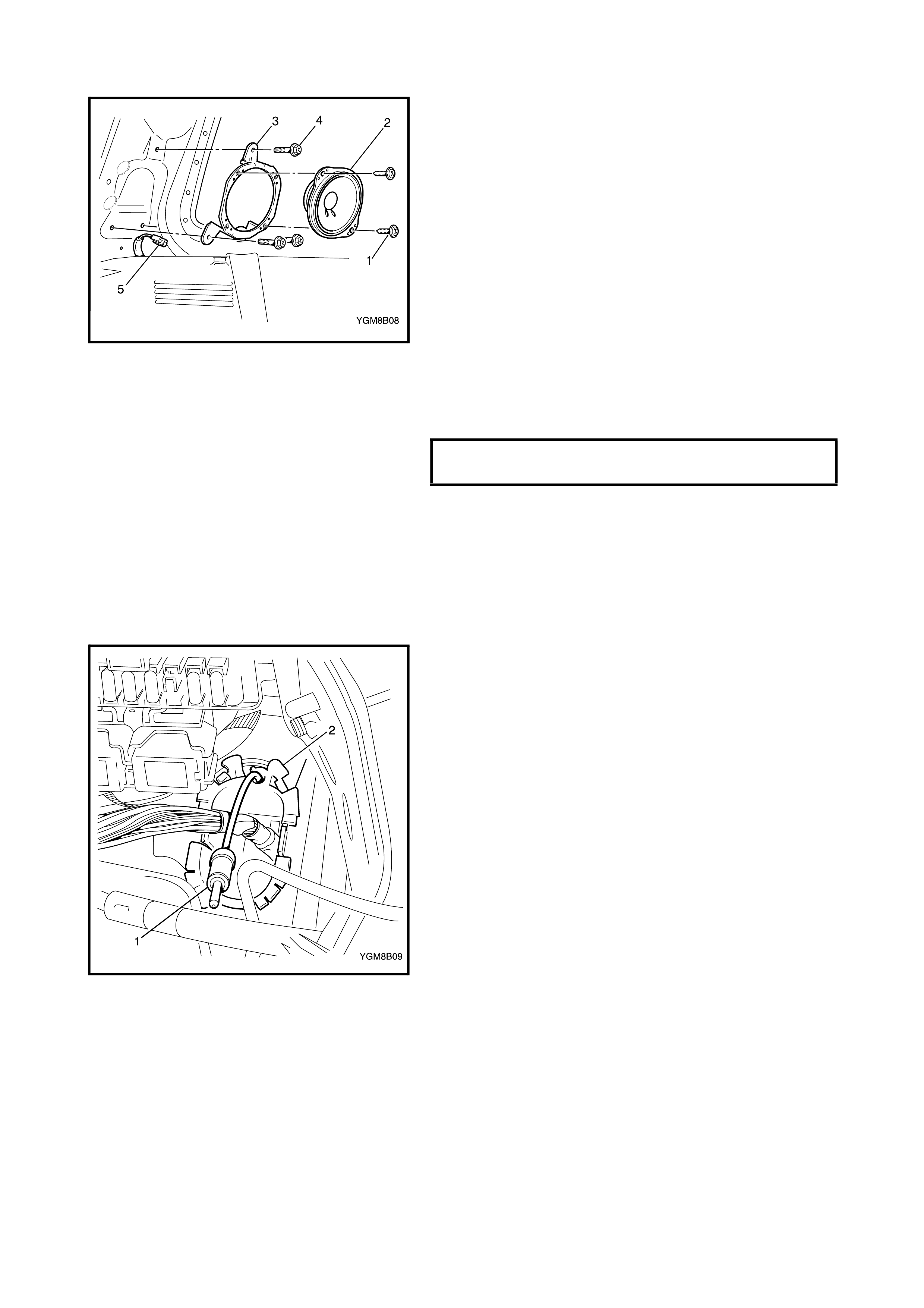
5. Remove the two screws (1) attaching the speaker (2)
to the speaker bracket (3) or, remove the three screws
(4) attaching the bracket to the vehicle.
6. Disconnect the wiring connector (5) and remove the
speaker.
INSTALLATION
1. Install in reverse order of removal.
NOTE: Tighten the seatbelt anchor bolt to the specified
torque.
2. When installation is complete, reinstate the audio unit
by entering the PIN code, refer to 2.1 AUDIO UNIT PIN
CODE in this Section.
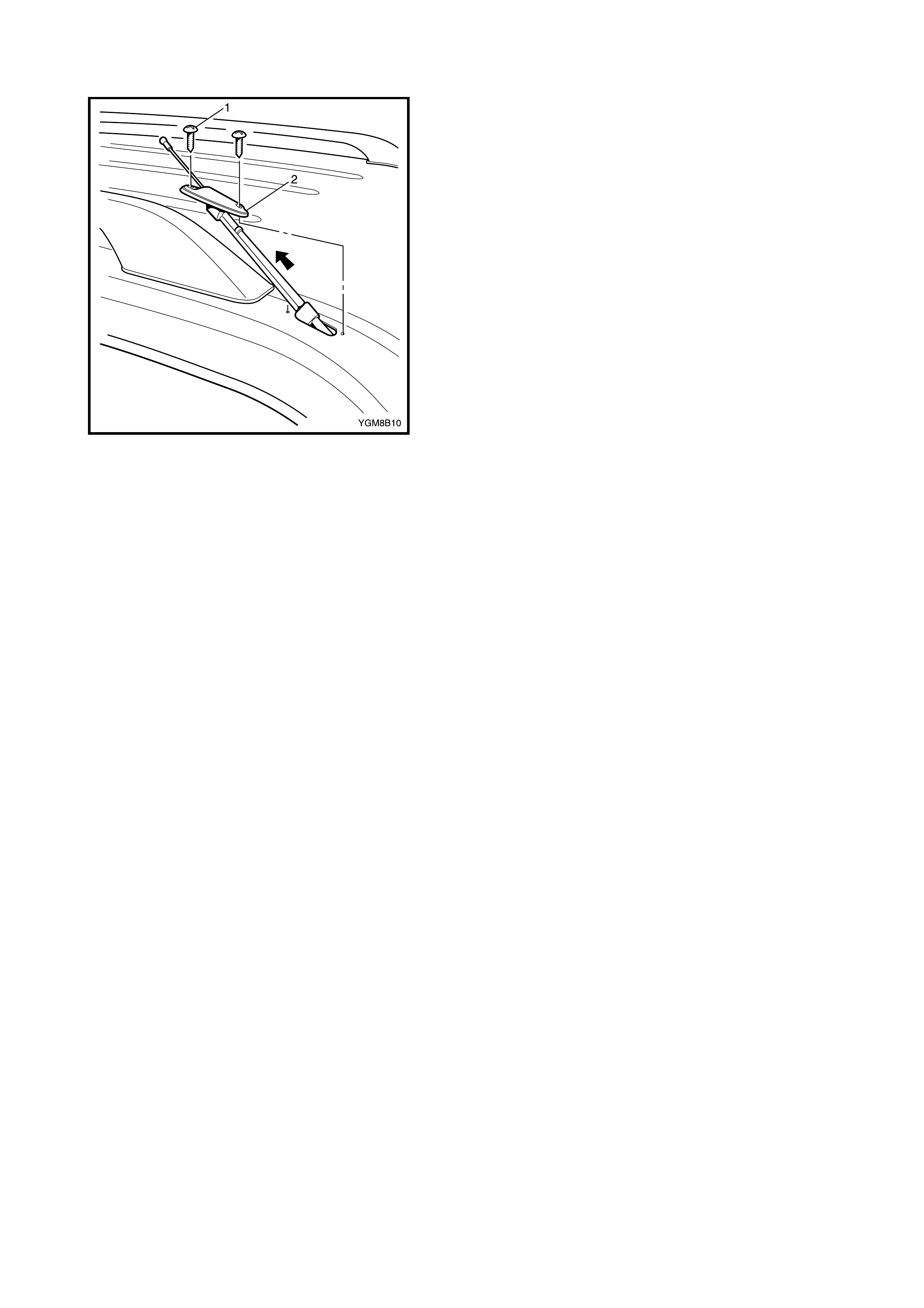
2.5 AN T ENNA
REMOVAL
1. Disconnect the negative battery cable at the battery.
2. Disconnect the antenna lead connector (1) from the
patch lead (2) under the steering column.
3. Tie a length of string securely to the antenna connec-
tor.
4. Unclip the harness retainer from the right-hand side
body pillar, behind the instrument panel.
5. Unhook the antenna lead from the retainer.
SEATBELT ANCHOR BOLT TORQUE
SPECIFICATION 35 Nm
6. Remove the two screws (1) attaching the antenna (2)
to the vehicle.
7. Withdraw the antenna from the vehicle, ensuring the
string does not pull through the hole in the pillar.
8. Untie the string from the connector and secure for
installation.
INSTALLATION
1. Install in reverse order of removal. When installation is
complete, reinstate the audio unit by entering the PIN
code, refer to 2.1 AUDIO UNIT PIN CODE in this
Section.