
SECTION 8G - IMMOBILISER CONTROL SYSTEM
1. GENERAL DESCRIPTION
1.1 WIRING DIAGRAM
1.2 ON-BOARD DIAGNOSTIC SYSTEM
(SELF-DIAGNOSIS FUNCTION)
2. DIAGNOSIS
2.1 PRECAUTIONS IN DIAGNOSING
TROUBLES
Precautions in Identifying
Diagnostic Trouble Code
Intermittent Troubles
2.2 DIAGNOSTIC FLOW TABLE
2.3 DIAGNOSTIC TROUBLE CODE (DTC)
CHECK (IMMOBILISER CONTROL
MODULE)
Using Tech 2
2.4 DIAGNOSTIC TROUBLE CODE (DTC)
CHECK (ECM)
Using Tech 2
Not Using Tech 2
2.5 DIAGNOSTIC TROUBLE CODE TABLE
Immobiliser Control Module
ECM
2.6 TABLE A - DTC IS NOT OUTPUT FROM
IMMOBILISER CONTROL MODULE
Wiri ng Diagra m
Inspection
2.7 DTC11/32 TRANSPONDER CODE NOT
MATCHED
Description
Inspection
2.8 DTC31 TRANSPONDER CODE NOT
REGISTERED
Description
Inspection
2.9 DTC12 FAULT IN IMMOBILISER
CONTROL MODULE
Description
Inspection
2.10 DTC13 NO TRANSPONDER CODE
TRANSMITTED OR COIL ANTENNA
OPENED / SHORTED
Wiring Diagram
Description
Inspection
2.11 DTC21 ECM / IMMOBILISER CONTR OL
MODULE CODE NOT MATCHED
(IMMOBILISER CONTROL MODULE
SIDE)
2.12 DTC81 P1623 ECM / IMMOBILIS ER
CONTROL MODULE CODE NOT
MATCHED (ECM SIDE)
2.13 DTC84 P1620 ECM / IMMOBILIS ER
CONTROL MODULE CODE NOT
REGISTERED
Description
Inspection
2.14 DTC P1622 FAULT IN ECM
Description
Inspection
WARNING:
For vehicles equipped with Supplement Restraint (Airbag) System
• Service on and around the airbag system components or wiring must be performed only by an
authorised H OLDEN retailer. Refer to Section 10B AIRBAG SY STEM COMP ONENTS AN D W IRING
LOCATION VIEW in GENERAL DESCRIPTION in order to confir m whether you are performing ser-
vice on or near the airbag system component s or wiring. Please observe all WARNINGS and SER-
VICE PRECAUTIONS, refer to Section 10B ON-VEHICLE SER VICE before perf orming service on or
around the airbag system components or wiring. Failure to follow WARNINGS could result in
unintentional activation of the system or could render the system inoperative. Either or these two
conditions may result in severe injury.
• Technical service work must not be started for at least 90 seconds after the ignition switch is
turned to the “LOCK” position and the negative cable is disconnected from the battery.
Otherwise, the system may be activated by reserve energy in the Sensing and Diagnostic Module
(SDM).
IMPORTANT:
Prior to connecting Tech 2 to the vehicle, refer to Section 0C TECH 2.
Techline

2.15 DTC22 IGNITION SWITCH CIRCUIT
OPEN/SHORT
Wiri ng Diagra m
Description
Inspection
2.16 DTC23 NO ECM / IMMOBILISER
CONTROL MODULE CODE
TRANSMITTED FROM ECM OR DLC
CIRCUIT OPENED / SHORTED
2.17 DTC83 (P1621) NO ECM / IMMOBILISER
CONTROL MODULE CODE
TRANSMITTED FROM IMMOBILISER
CONTROL MODULE OR DLC CIRC UIT
OPEN ED / SH ORT E D
Wiri ng Diagra m
Description
Inspection
2.18 INSPECTION OF ECM, IMMOBILISER
CONTROL MODULE AND ITS CIRCUIT
Voltage Check
3. ON-VEHICLE SERVICE
3.1 PRECAUTIONS IN HANDLING
IMMOBILISER CONTROL SYSTEM
3.2 IMMOBILISER CONTROL MODULE
Removal
Installation
4. IMMOBILISER FUNCTIONS
5. HOW TO REGISTER IGNITION KEY
6. PROCEDURE AFTER ICM &/OR ECM
REPLACEMENT
7. SPECIAL TOOLS
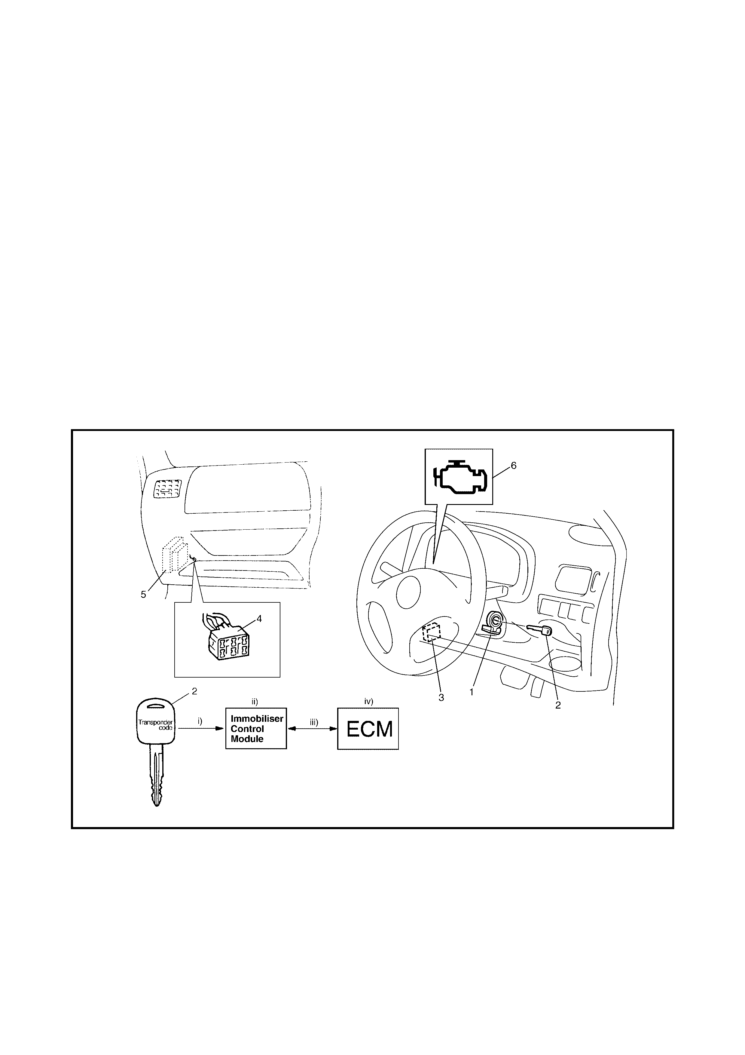
1. GENERAL DESCRIPTION
The immobiliser control system is designed to prevent vehicle theft and consists of the following components:
• Engine control module (ECM),
• Immobiliser control module (1) with coil antenna,
• Ignition key (2) with built-in transponder.
Operation of this system is as follows.
i. Each ignition key has its own code (transponder code) stored in memory. When the ignition switch is
turned O N, the immob iliser control modul e rea ds the tr anspon der code throu gh the coi l ante nna in stalled
with the steering lock assembly.
ii. The immob iliser c ontro l modu le com pares the tr ansp onder co de rea d in Step i. with tha t regi stered i n the
immobiliser control module memory and checks if they match.
iii. When it is confirmed that the two transponder codes match each other, the immobiliser control module
and ECM check if the ECM / immobiliser control module codes registered match.
iv. Only when it is confirmed that the ECM / immobiliser control module codes match is the engine able to
start. If th e t ra ns pon der c od es in Step ii. or the E CM / immobili se r c ontr ol m odu le co des in Ste p i ii. d o n ot
match, the ECM will stop operation of the injectors and spark plugs.
Legend
1. Immobiliser control module with coil antenna 4. Monitor connector
2. Ignition key with built-in transponder 5. ECM
3. Data link connector (DLC) 6. Malfunction indicator lamp (MIL)
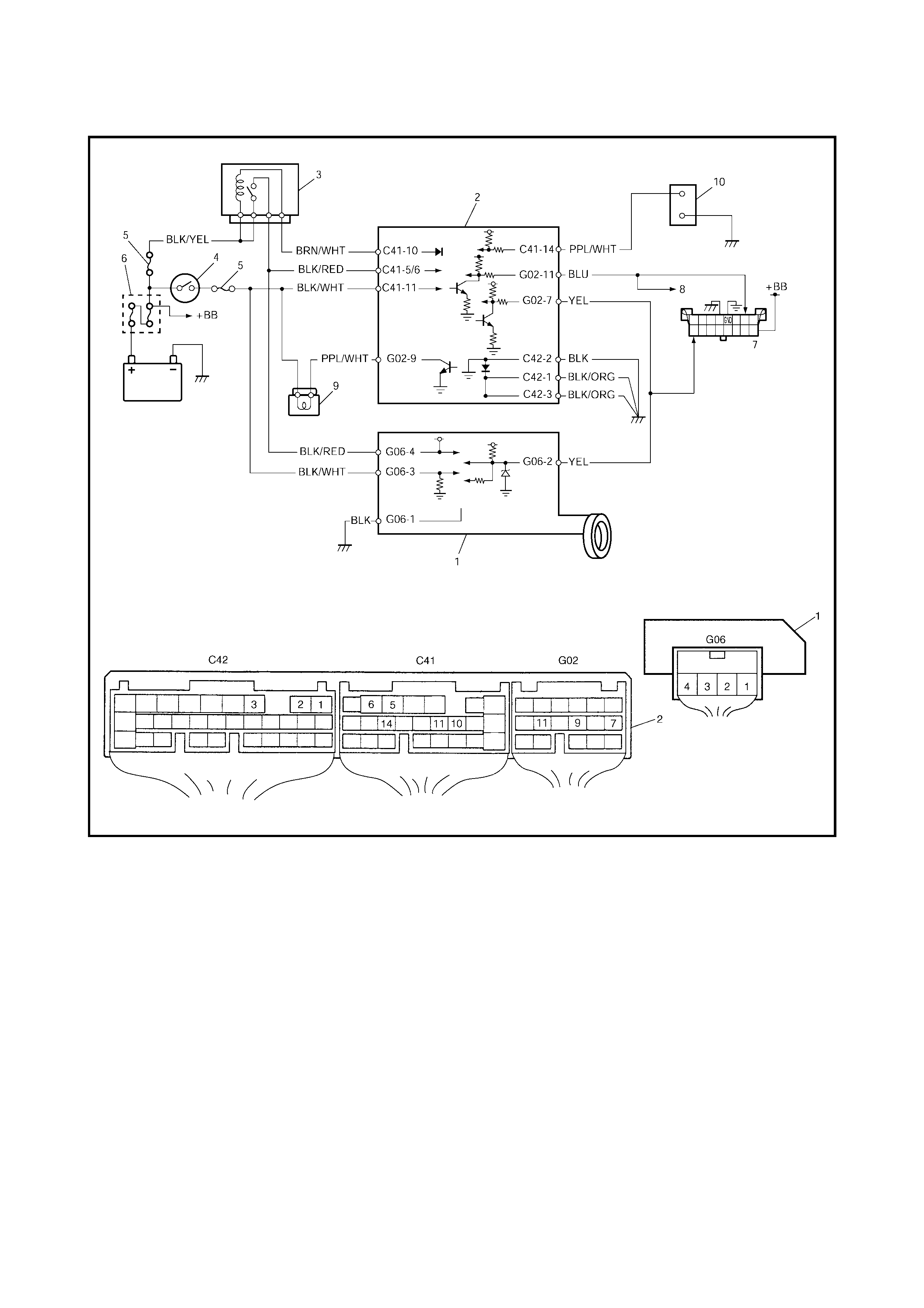
1.1 WIRING DIAGRAM
Legend
1. Immobiliser Control Module 6. Main fuse
2. ECM 7. Data Link Connector (DLC)
3. Main relay 8. To ABS control module, SDM and TCM
4. Ignition switch 9. Malfunction Indicator Lamp (MIL)
5. Fuse 10. Monitor connector
1.2 ON-BOARD DIAGNOSTIC SYSTEM
(SELF-DIAGNOSIS FUNCTION)
The immobiliser control module and ECM diagnose faults
which may occur in the following areas when the ignition
switch is ON.
ECM:
• ECM / immobiliser control module code
• Serial data link circuit
•ECM
Immobiliser Control Module:
• Transponder code
• Coil antenna
• ECM / immobiliser control module code
• Serial data link circuit
• Immobiliser control module
• Ignition signal
With the ignition switch ON and engine stationary, the
Malfunction Indicator Lamp (MIL) will indicate if a failure
has occurred in either the engine management or
immobiliser systems.
Malfunction Indicator Lamp ON
• No fault exists in the immobiliser control system.
Malfunction Indicator Lamp Flashing:
• ECM or immobiliser control module has detected some
fault in the immobiliser control system.
NOTE:
• Immobiliser system DTC’s can only be viewed with
TECH 2.
• Engine Management System DTC’s can be displayed
either on TECH 2 or as MIL flash codes.
NOTE:
As soon as the ignition switch is turned ON, the ECM
and immobiliser control module perform a diagnostic
self-check of the immobiliser control system. While the
diagnostic self-check is performed, the
Malfunction Indi-
cator Lamp
rema ins ON . If no fa ult is d etected , the MIL
will remain illuminated until the engine is started or the
ignition is turned OFF.
Should a fault be detected, the MIL will begin flashing
aft er ap proxima tely 3 seconds . If no faul t is detec te d, the
MIL will remain illuminated until the engine is started or
the igni tio n is tu rned OFF.
When the ECM and immobiliser
control module detects a trouble, it stores the DTC corre-
sponding to the exact trouble area in the ECM and immobi-
liser control module memory.
DTCs stored in memory of each control module can be
read by using the procedure described in
2.3 DIAGNOSTIC TROUBLE CODE CHECK
(IMMOBILISER CONTROL MODULE) and
2.4 DIAGNOSTIC TROUBLE CODE CHE CK (ECM) in this
Section.

2. DIAGNOSIS
2.1 PRECAUTIONS IN DIAGNOSING TROUBLES
PRECAUTIONS IN IDENTIFYING DIAGNOSTIC TROUBLE CODE
ECM
• Do no t d isco nne ct the E CM co nne cto rs, ba tter y o r the E CM gr oun d wi re h ar ness from the e ngi ne be for e
identifying Diagnostic Trouble Codes (DTCs) indicated by the Malfunction Indicator Lamp (MIL) or
TECH 2, .
Removing the ECM power supply or ground connections will clear any DTCs stored in the ECM memory.
• If an abnormality or malfunction exists in two or more areas, the Malfunction Indicator Lamp (MIL) indi-
cates the applicable Diagnostic Trouble Code s (DTCs) three times. Flashing of these codes is repeated
as long as the diagnosis terminal is grounded and the ignition switch remains ON.
• Diagnostic Trouble Codes (DTCs) are displayed in the order of priority.
Immobiliser Control Module
• Diagnostic Trouble Codes (DTCs) are displayed in the order of priority.
INTERMITTENT FAULTS
• There maybe a case where TECH 2 or the Malfunction Indicator Lamp (MIL) indicate a Diagnostic Trouble
Code (DTCs) representing a fault which occurred temporarily and is no longer present. In such case,
parts may be unne ce ssar i ly r eplac ed . To prev en t thi s oc cu rri ng, fol low the instr uc ti ons gi ve n b elo w whe n
checking by using 2.2 DIAGNOSTIC FLOW TABLE in this Section.
When the fault can be identified, it is not an intermittent one. In this case, perform the following:
• Check the coil antenna, ignition key, wires and each connection. If they are all in good condition, sub-
stitute a known-good ECM and recheck.
When the fault cannot be identified but TECH 2 indicates a trouble code:
• Attempt to diagnose the fault by using that DTC.
• If the igniti on key, coil a nten na, wi res and c on nec tio ns ar e al l in good con di tio n, turn O F F the i gnition
switch and then ON.
• If a DTC has set again, substitute a known-good ECM or immobiliser control module and check again.
If TECH 2 th en ind icate s “N o fa ult fo und ”, it me ans that the fau lt is inter m itte nt. In this c ase, re check
wires and connections.
2.2 DIAGNOSTIC FLOW TABLE
NOTE:
After replacing a known-good ECM, register the ECM /
immobiliser control module
code in the
ECM by perf orming the procedure described in 6. PROCEDURE AFTER ECM REPLACEMENT in this
Section.
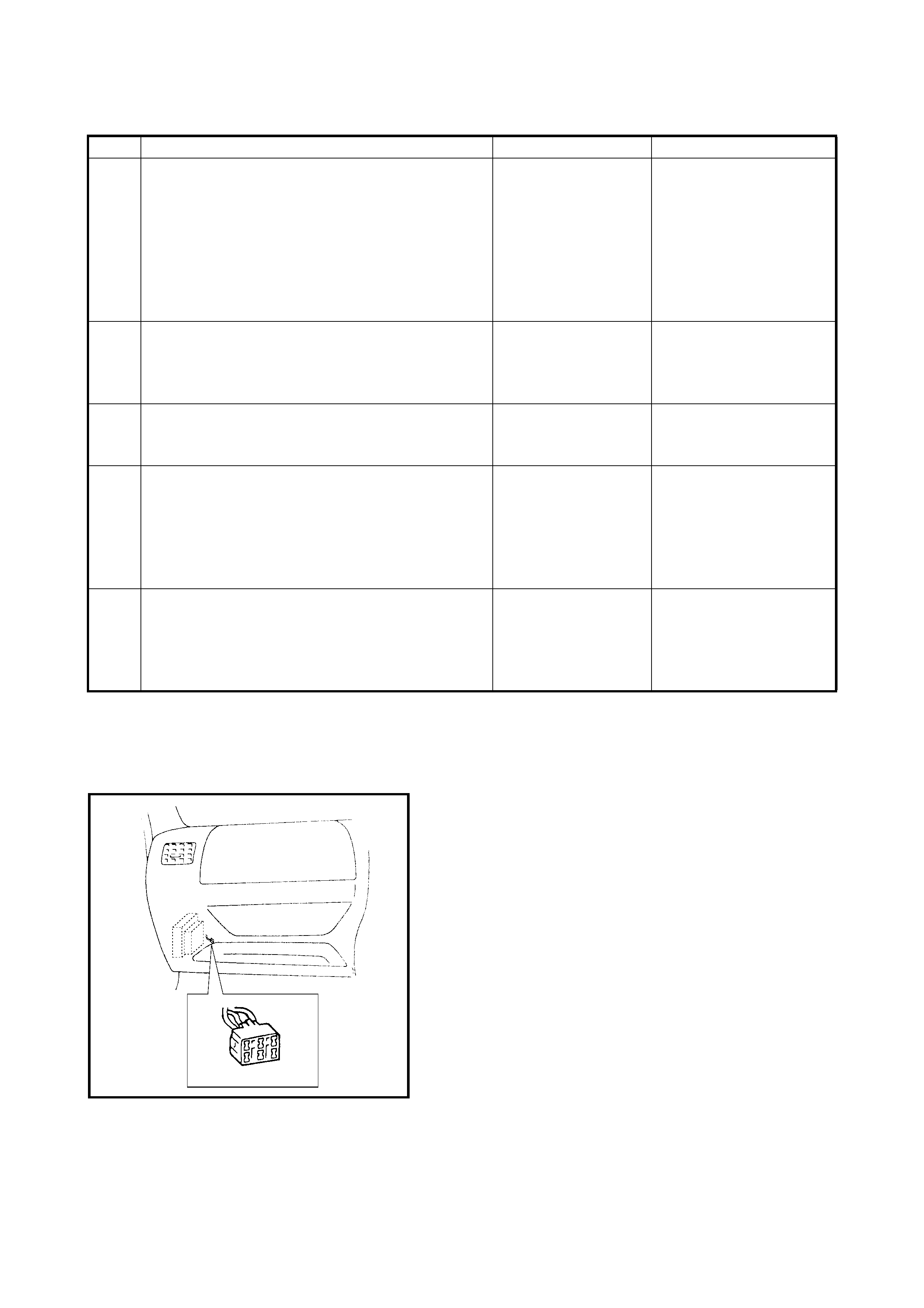
Fig. 1 for Step 1
Step Action Yes No
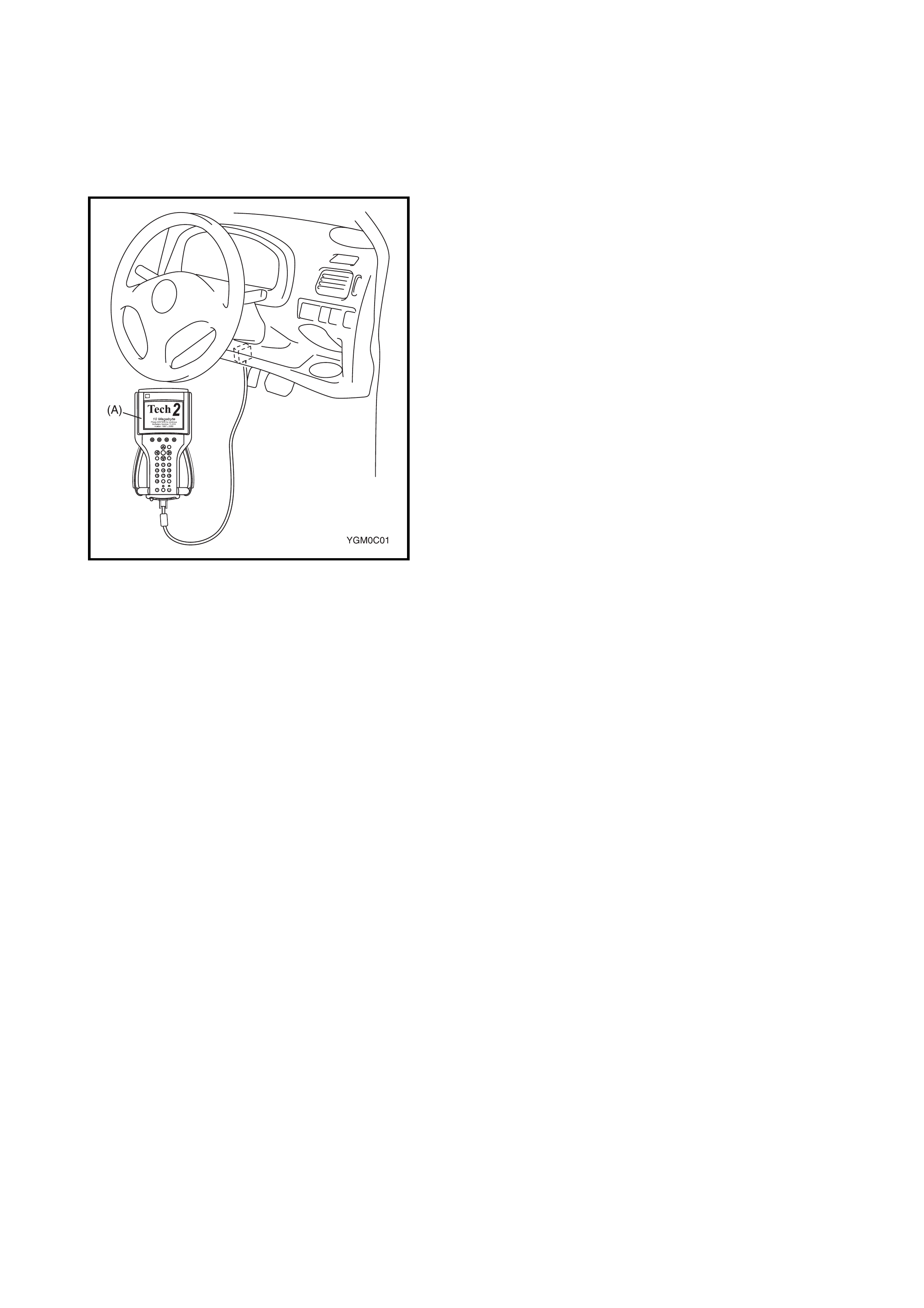
1 1. Ensure the diagnosis switch terminal in the
monitor connector is not grounded with a
service wire. See Fig.1.
2. Check the Malfunction Indicator Lamp while
the ignition switch is ON (but without starting
the engine). See Fig.2.
Does the malfunction indicator lamp flash?
Go to Step 3. If the malfunction indica-
tor lamp remains ON, go
to Step 2.
If the malfunction indica-
tor lamp remains OFF, go
to MALFUCTION
INDICATOR LAMP
CHECK in Section 6.
2 Using a service wire, ground the diagnostic switch
terminal in the monitor connector. See Fig.3.
Does the malfunction indicator lamp flash?
The immobiliser con-
trol system is in good
condition.
Go to MALFUCTION
INDICATOR LAMP
CHECK in Section 6.
3 Does the malfunction indicator lamp flash as
Fig.4? Go to Step 4. Go to MALFUCTION
INDICATOR LAMP
CHECK in Section 6.
4 1. Check DTC stored in the immobiliser control
module, refer to 2.3 DIAGNOSTIC
TROUBLE CODE CHECK (IMMOBLISER
CONTROL MODULE) in this Section.
Are there any DTC(s) stored?
Go to flow table for
that DTC. Go to Step 5.
5 1. Check DTC stored in ECM, refer to
2.4 DIAGNOSTIC TROUBLE CODE
CHECK (ECM) in this Section.
Are there any DTC(s) stored?
Go to flow table for
that DTC. Substitute a known good
ECM and recheck.
See NOTE below.
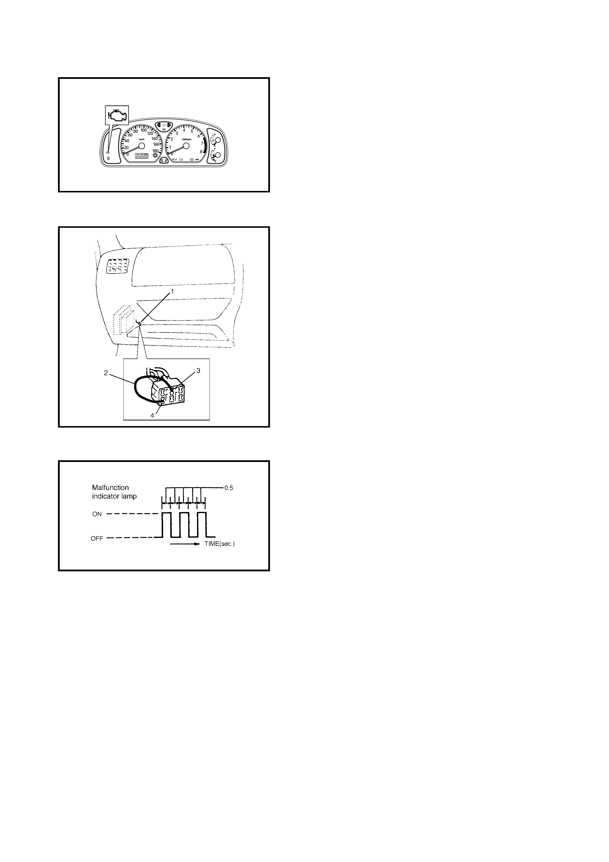
Fig. 2 for Step 1
Legend
Fig. 3 for Step 2
Fig. 4 for Step 3
1. Monitor connector
2. Service wire
3. Diagnostic switch terminal
4. Ground terminal
2.3 DIAGNOSTIC TROUBLE CODE (DTC) CHECK
(IMMOBILISER CONTROL MODULE)
USING TECH 2
1. Turn ignition switch OFF.
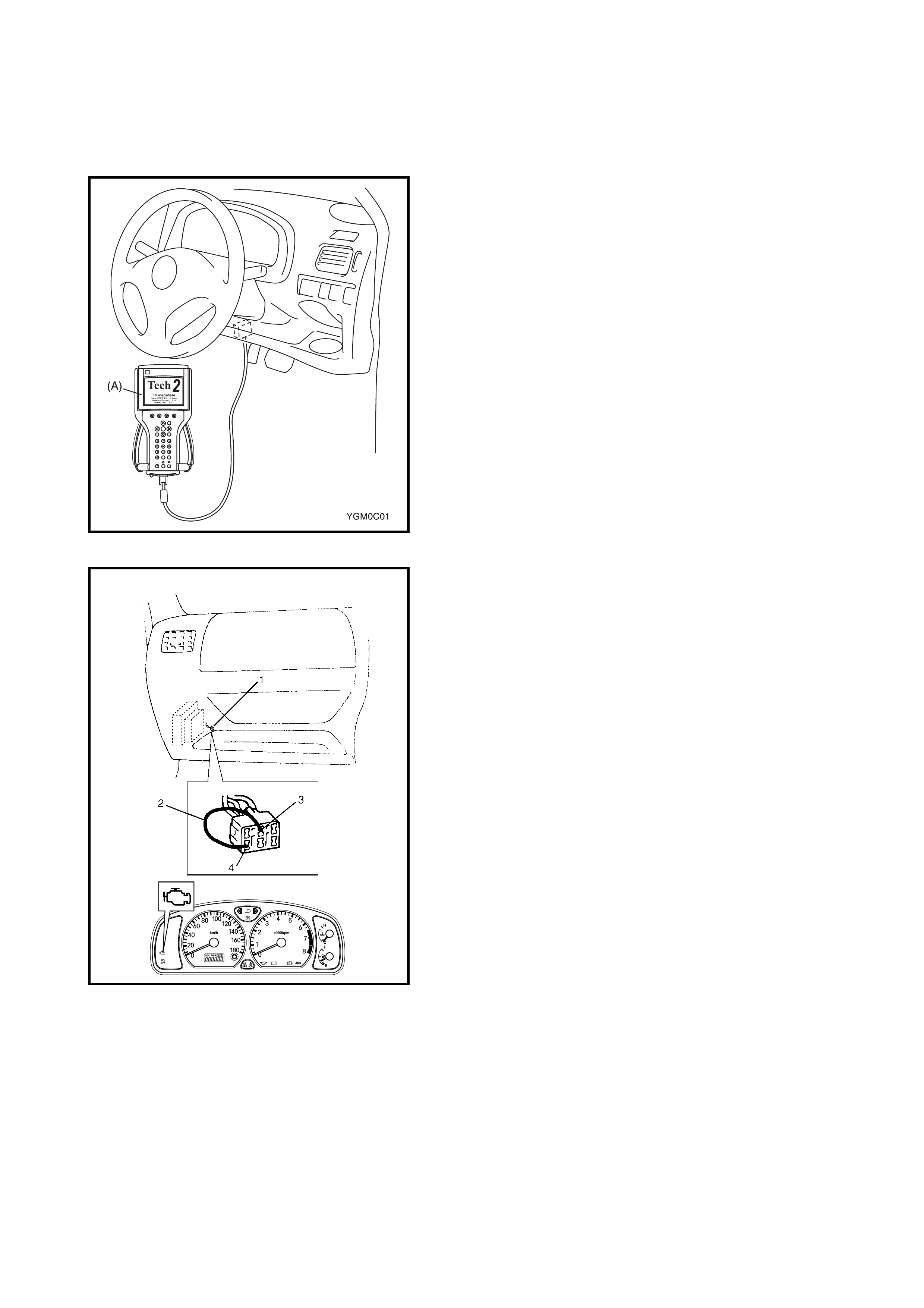
2. After fitting the card into Tech 2 (A), connect it to the
data link connector (DLC) (1) located on underside of
instrument panel at driver’s seat side.
3. Turn the ignition switch ON.
4. Read the DTC stored in the immobiliser control module
accord ing to i nstruct ion s displ ayed o n Tech 2 and pri nt
it or write it down. Refer to the Tech 2 operator's
manual for further details.
If communication between Tech 2 and the immobiliser
control module is not possible, go to 2.6 TABLE A D TC
IS NOT OUTPUT FROM IMMOBILISER CONTROL
MODULE.
NOTE:
When reading DTCs stored in the
immobiliser
contro l module
using Tech 2, select BCM from the appli-
cation s menu and IMMOBILI SER fro m the sel ect syste m
menu displayed on Tech 2.
5. After completing the check, turn ignition switch OFF
and disconnect Tech 2 from the data link connector
(DLC).
2.4 DIAGNOSTIC TROUBLE CODE (D TC) CHECK (ECM)
USING TECH 2
1. Turn ignition switch OFF.
2. After fitting the card into Tech 2 (A), connect it to the
data link connector (DLC) (1) located on underside of
instrument panel at driver’s seat side.
3. Turn ignition switch ON.
4. Read the DTC stored in the ECM according to the
instructions displayed on Tech 2, refer
Section 0C TECH 2 for further details.
If communication between Tech 2 and the ECM is not
possibl e, c he ck if Tech is c om mu nic ab le b y c on nec tin g
it to the ECM in another vehicle. If communication is
possible in this case, the Tech 2 is in good condition.
Check the data link connector and serial data line
(circuit) in the vehicle with which communication was
not possibl e.
NOT USING TECH 2
1. Ground the monit or connector (1) using a s ervice wir e
(2) connector between the ground terminal (3) and
diagnostic switch terminal (4).
2. Turn ignition switch ON.
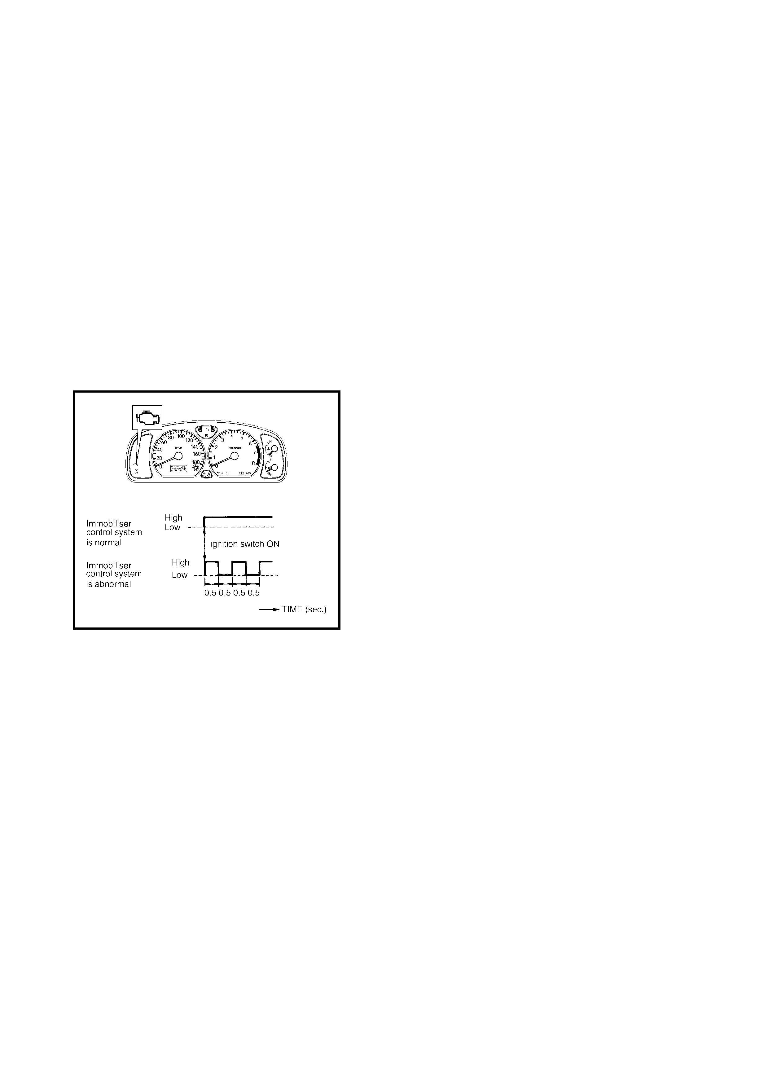
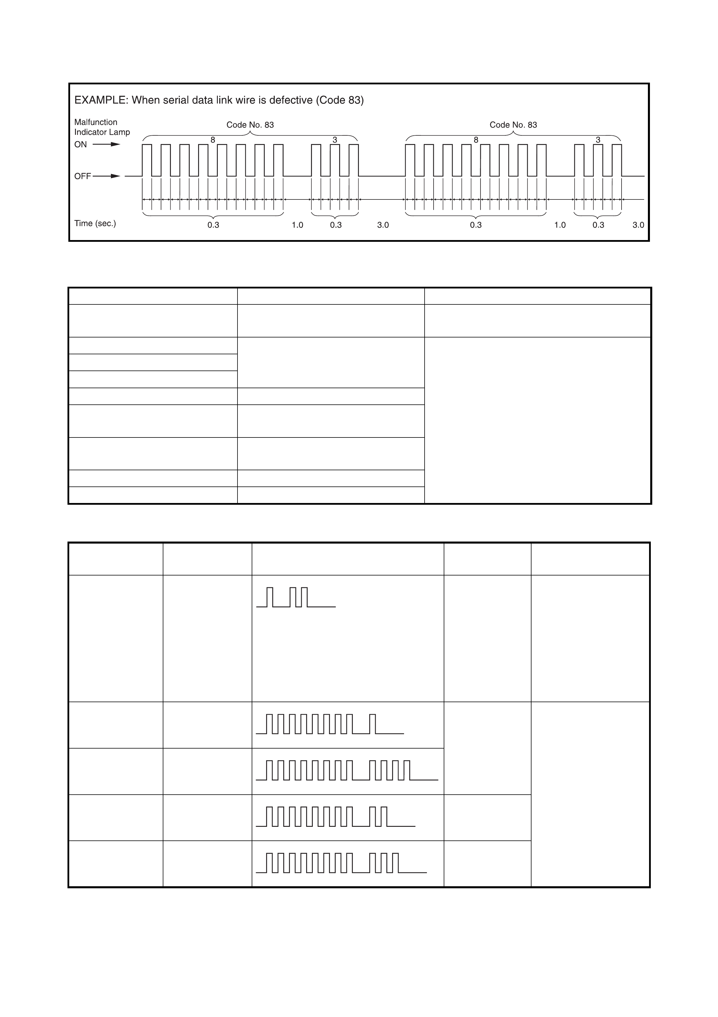
3. Read the DTC from the flashing pattern of the malfunc-
tion indicator lamp (MIL) as shown in the example
below and write it down.
For details of the DTCs, refer to ECM in
2.5 DIAGNOSTIC TROUBLE CODE TABLE in this
Section.
If the lamp remains ON, refer to Malfunction Indicator
Lamp (MIL) Check in 2.4 ENGINE DIAGNOSTIC
FLOW TABLE in Section 6.
NOTE: If an abnormality or malfunction exists in two or
more a reas, the m alfunction ind icator lamp (MIL) indic ates
the applicable codes three times each. Flashing of these
codes is repeated for as long as the diagnosis terminal is
grounded and the ignition switch is ON.
4. After completing the check, turn the ignition switch
OFF and disconnect the service wire from the m onitor
connector.
2.5 DIAGNOSTIC TROUBLE CODE TABLE
IMMOBILISER CONTROL MODULE
ECM
Refer to Section 6 for how to read diagnostic codes (DTCs) from a flashing malfunction indicator lamp.
DTC (indicated on Tech 2) DIAGNOSTIC AREA DIAGNOSIS
NO DTC Normal (No code) This code appears when no other codes
are identified.
1 1 Transponder code Diagnose trouble according to Diagnostic
Flow Table corresponding to each code
No.
31
32
12 Immobiliser control module
13 Coil antenna or ignition key with
built- in trans pon der
21 ECM / immobiliser control module
code
22 Ignition switch circuit
23 Serial data link circuit
DTC (indicated
on Tech 2) DTC (indicated
on MIL) MIL PATTERN DIAGNOSTIC
AREA DIAGNOSIS
NO DTC 12 Normal This code appears
when it is confirmed
that no other trouble
codes are set for
immobiliser control
system or engine and
emission control sys-
tem.
P1623 81 ECM / immobil-
iser control
module code
Diagnose trouble
according to
DIAGNOSTIC FLOW
TABLE
corresponding to
each code No.
P1620 84
P1622 82 ECM
P1621 83 Serial data link
wire
2.6 TABLE A - DTC IS NOT OUTPUT FROM IMMOBILISER CONTROL MODULE
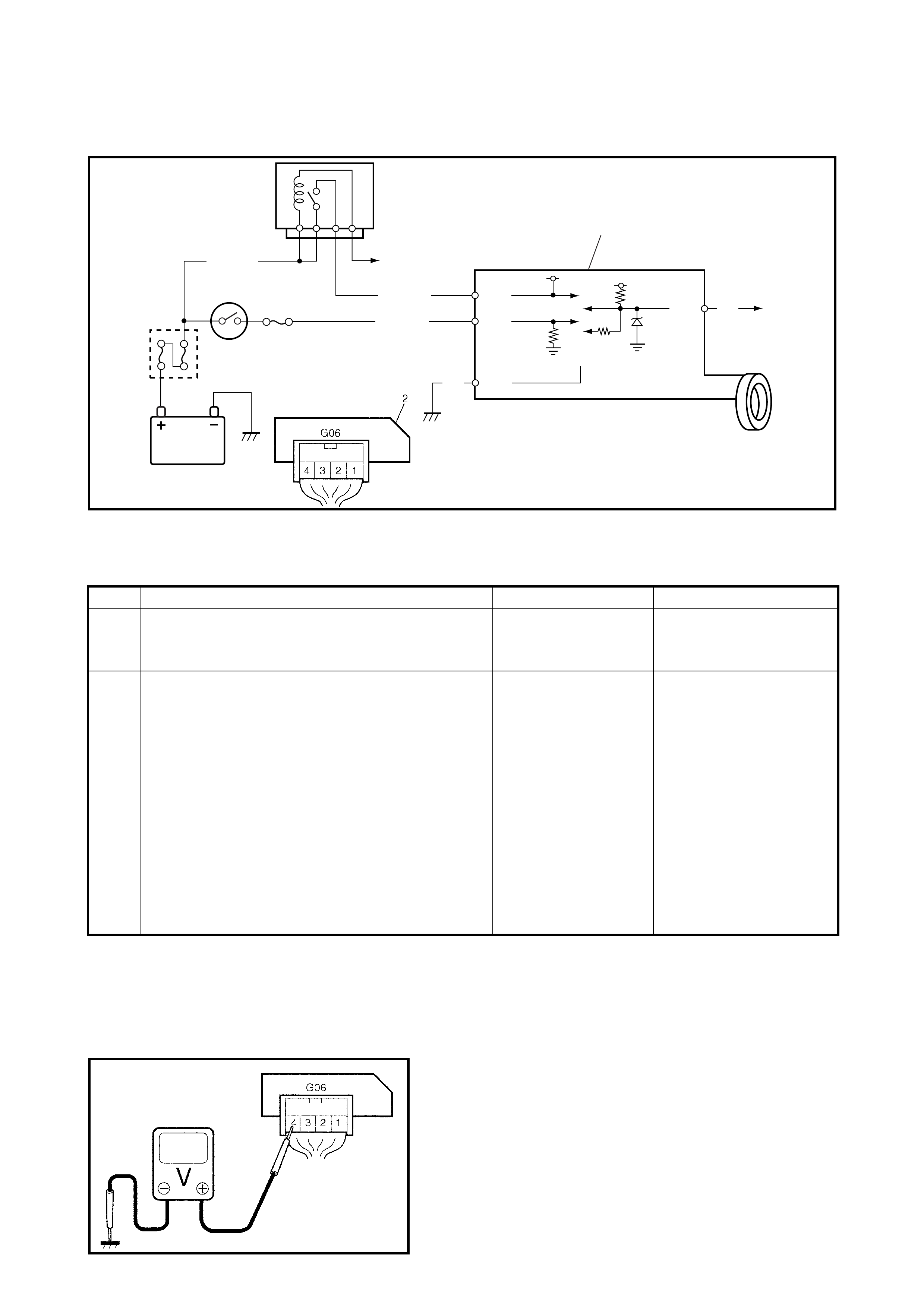
WIRING DIAGRAM
Legend
INSPECTION
NOTE:
After replacing with a known good Immobiliser control module, register the ECM / immobiliser
control module code in ECM and Transponder code and ECM / immobiliser control module code in
immobiliser control module by performing the procedure described in 6. PROCE DURE AFTER
IMMOBILISER CONTROL MODULE REPLACEMENT in this Section.
Fig. 1 for Step 1
BLK/RED
BLK/WHT
BLK/WHT
BLK
2
1
3
YEL
BLK/YEL
G06-4
G06-3
G06-1
G06-2
1. To ECM 2. Immobiliser control module 3. To #9-pin in DLC
Step Action Yes No
1 Check voltage between G06-4 terminal and body
ground with ignition switch turned ON. See Fig 1.
Is it 10 – 14 V?
Go to Step 2. BLK/RED wire open or
short to ground.
2 1. Disconnect connector (1) at immobiliser
control module.
Is there conti nuity between co nnecto r ter minal
G06-1 and body ground? See Fig 2.
• Poor G06-4 or
G06-1 connection
• Poor #9-pin con-
nection in DLC
• Serial data line
YEL open or short
to ground
If connections and
line are OK, subs ti-
tute a known good
Immobiliser Control
Module and recheck.
See NOTE below.
BLK wire open .
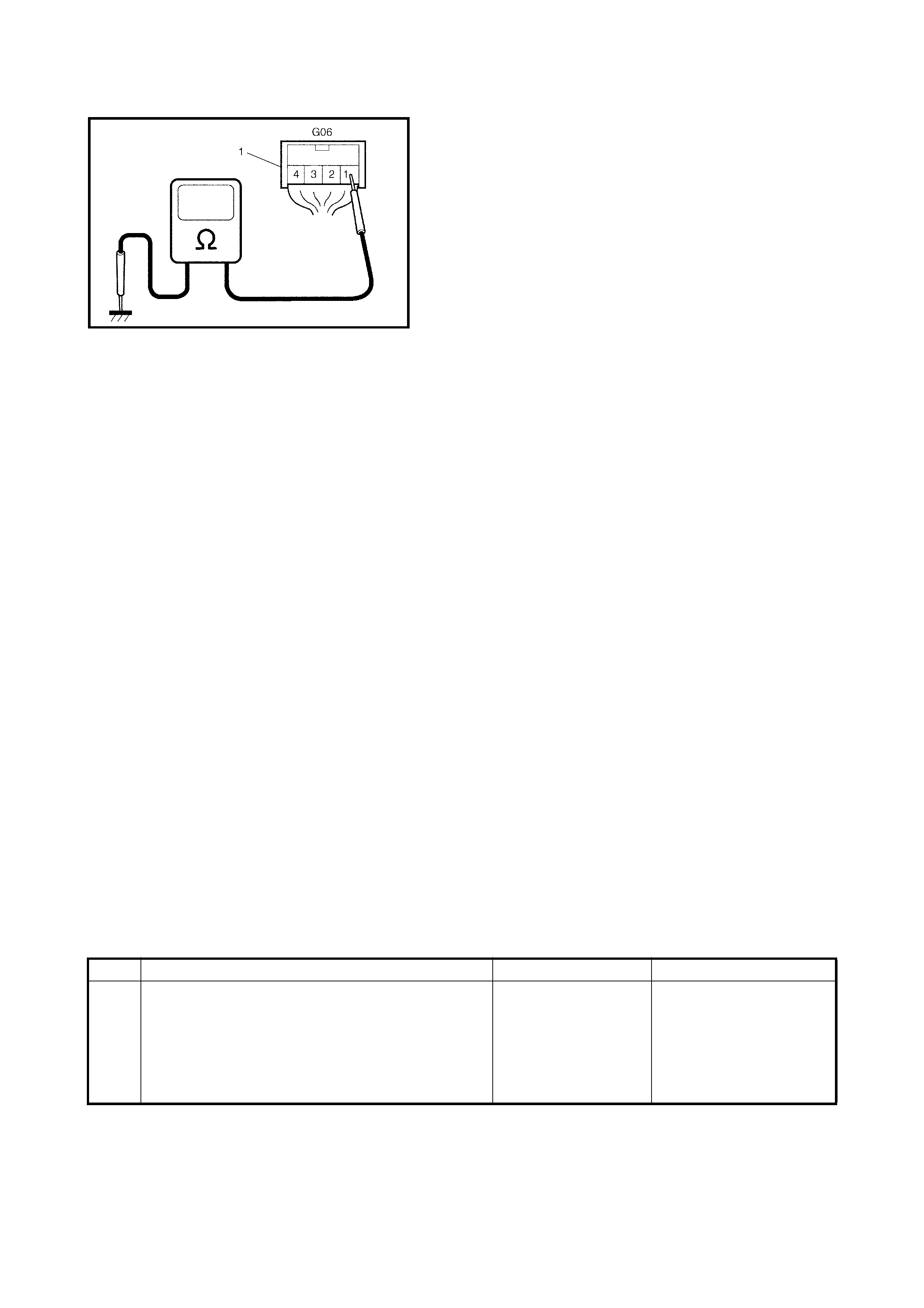
Fig. 2 for Step 2
2.7 DTC11/32 TRANSPO NDER CODE NOT MATCHE D
DESCRIPTION
The immobiliser control module checks if the transponder code transmitted from the ignition key and the code
registered in the immobiliser control module match when the ignition switch is ON. If they do not, DTC 11 and/
or 32 are set.
INSPECTION
Register the ignition key with built-in transponder using Tech 2 and performing following steps.
1. Register the transponder code in the immobiliser control module, refer to 5. HOW TO REGISTER
IGNITION KEY in this Section.
2. Turn the ignition switch OFF, then turn it ON and check that DTC11 and/or 32 are not set.
2.8 DTC31 TRANSPONDER CODE NOT REGISTERED
DESCRIPTION
The immobiliser control module checks if the transponder code transmitted from the ignition key and the code
registered in immobiliser control module match when ignition switch is ON. If there is no transponder code
registered in immobiliser control module, this DTC is set.
INSPECTION
Register the ignition key with built-in transponder using Tech 2 and performing following steps.
1. Register the transponder code in the immobiliser control module, refer to 5. HOW TO REGISTER
IGNITION KEY in this Section.
2. Turn the ignition switch OFF, then turn it ON and check that DTC31 is not set.
2.9 DTC12 FAULT IN IMMOBILISER CONTROL MODULE
DESCRIPTION
This DTC is set when an internal fault is detected in the immobiliser control module.
INSPECTION
NOTE:
After replacing with a known good Immobiliser control module, register the ECM / immobiliser
control module code in ECM and Transponder code and ECM / immobiliser control module code in
immobiliser control module by performing the procedure described in 6. PROCE DURE AFTER
IMMOBILISER CONTROL MODULE REPLACEMENT in this Section.
Step Action Yes No
1 1. Ignition switch OFF.
2. Disconnect the immobiliser control module
connectors.
3. Check for proper connection to immobiliser
control module at all terminals.
Are they in good condition?
Substitute a known
good immobiliser
control module and
recheck.
See NOTE below.
Repair or replace.
2.10 DTC13 NO TRANSPONDE R CODE TRANSMITTED OR COIL
ANTENNA OPENED / SHORTED
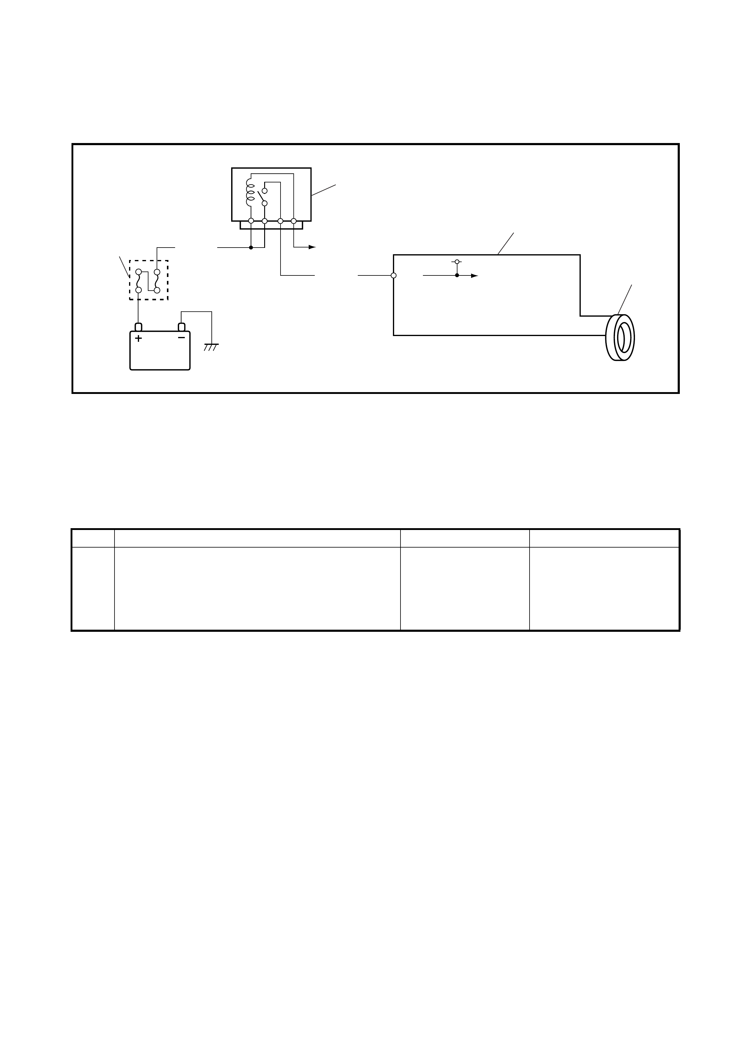
WIRING DIAGRAM
Legend
DESCRIPTION
The immobiliser control module energises the coil antenna when the ignition switch is ON and reads the tran-
sponde r code from the ignition ke y. Whe n the immobil iser control mo dule cannot rea d the transponde r code
from the ignition key, even when the coil antenna is energised, this DTC is set.
INSPECTION
NOTE:
After replacing with a known good Immobiliser control module, register the ECM / immobiliser
control module code in ECM and Transponder code and ECM / immobiliser control module code in
immobiliser control module by performing the procedure described in 6. PROCE DURE AFTER
IMMOBILISER CONTROL MODULE REPLACEMENT in this Section.
BLK/RED
BLK/YEL
G06-4
2
3
4
5
1. Main fuse 2. Main relay 3. Immobiliser control module 4. Coil antenna 5. To ECM
Step Action Yes No
1 Check that the ignition key a transponder key? Substitute a known
good immobiliser
control module and
recheck.
See NOTE below.
Replace ignition key with
correct one and follow
Diagnostic Flow Table
again.

2.11 DTC21 ECM / IMMOBILISER CONTROL MODULE CODE NOT MATCHED
(IMMOBILISER CONTROL MODULE SIDE)
2.12 DTC81 P1623 ECM / IMMOBILISER CONTROL MODULE CODE NOT MATCHED
(ECM SIDE)
2.13 DTC84 P1620 ECM / IMMOBILISER CONTROL MODULE CODE NOT
REGISTERED
DESCRIPTION
•DTC21
The immobiliser control module checks if the ECM / immobiliser control module code transmitted from the
ECM a nd the code regi stered in immob iliser control module ma tch whe n the ig nition switc h is ON. I f they
do not, this DTC is set.
•DTC81 P1623
The ECM checks if the ECM / immobiliser control module code transmitted from the immobiliser control
module a nd the code r egister ed in the EC M matc h when ign ition sw itch i s ON. If th ey do not, thi s DTC is
set.
•DTC84 P1620
The E CM checks if the co de transmitted from immobi liser contr ol module and the code r egistered i n the
ECM match when ignition switch is ON. If there is no ECM / immobiliser control module code registered in
ECM, this DTC is set.
INSPECTION
Perform procedure described in 6. PROCEDURE AFTER ECM REPLACEMENT in this Section.
2.14 DTC P1622 FAULT IN ECM
DESCRIPTION
This DTC is set when an internal fault is detected in the ECM.
INSPECTION
NOTE:
After replacing with a known good ECM, register the ECM / immobiliser control module code in
the ECM, refer 6 . PROCEDURE AFTER ECM REPLACEMENT in this Section.
Step Action Yes No
1 1. Ignition switch OFF.
2. Disconnect the ECM connectors.
3. Check for proper connection to the ECM at all
terminals.
Are they in good condition?
Substitute a known
good ECM and
recheck.
See NOTE below.
Repair or replace.

2.15 DTC22 IGNITION SWITCH CIRCUIT OPEN/SHORT
WIRING DIAGRAM
Legend
DESCRIPTION
The immobiliser control module monitors the ignition signal when the ignition switch is ON. This DTC is set
when no ignition signal input is detected by the immobiliser control module.
INSPECTION
NOTE:
After replacing with a known good Immobiliser control module, register the ECM / immobiliser
control module code in ECM and Transponder code and ECM / immobiliser control module code in
immobiliser control module by performing the procedure described in 6. PROCE DURE AFTER
IMMOBILISER CONTROL MODULE REPLACEMENT in this Section.
Fig. 1 for Step 1
BLK/WHT
BLK/WHT G06-3
12
3
1. Main fuse 2. Ignition switch 3. Immobiliser control module
Step Action Yes No
1 Check voltage between immobiliser control mod-
ule (1) connector terminal G06-3 and body ground
with ignition switch turned ON. (See Fig. 1)
Is it 10 – 14V?
Poor G06- 3 term in al
connection.
If connection is OK,
substitute a known
good immobiliser
control module and
recheck.
See NOTE below.
BLK/WHT wire open or
short.
2.16 DTC23 NO ECM / IMMOBILISER CONT ROL MODULE CODE TRANSMITTED
FROM ECM OR DLC CIRCUIT OPENED / SHORTED
2.17 DTC83 (P1621) NO ECM / IMMOBILISE R CONTROL MODULE CODE
TRANSMITTED FROM IMMOBILISER CONTROL MODULE OR DLC CIRCUIT OPENED
/ SHORTED
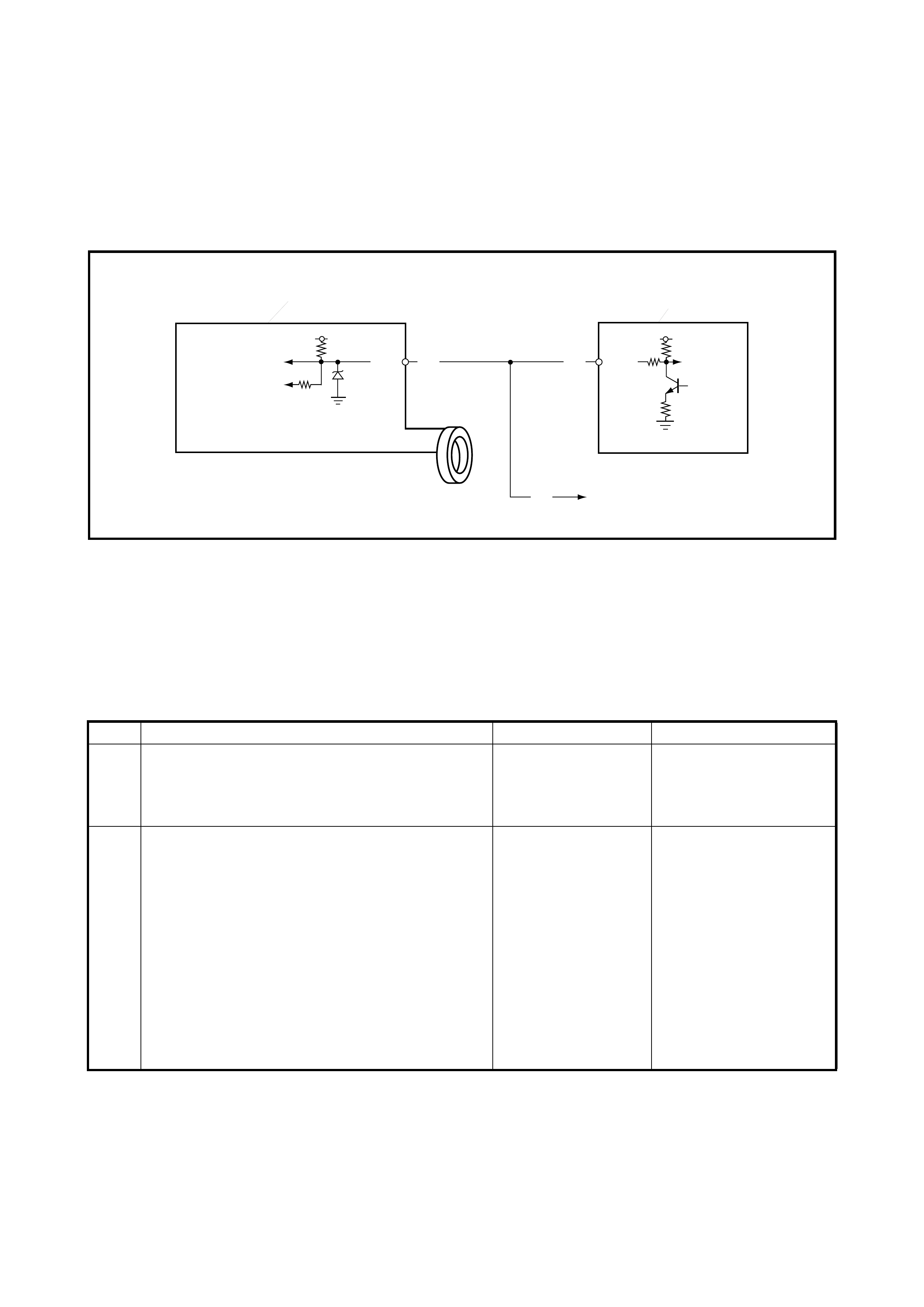
WIRING DIAGRAM
Legend
DESCRIPTION
When the ignition switch is ON, the immobiliser control module requests the ECM and the ECM requests
immobiliser control module to transmit the EC M / immobiliser control module code. If the ECM / immobiliser
control module code is not transmitted from the ECM or immobiliser control module, the immobiliser control
module sets DTC23 and ECM sets DTC83 (P1621).
INSPECTION
NOTE:
• After rep lacing with a known g ood ECM, r egister t he ECM / immo biliser c ontrol module c ode in the ECM
and by performing the procedure described in 6. PROCEDURE AFTER ECM REPLACEMENT in this
Section.
• After replacing with a known good Immobiliser control module, register the ECM / immobiliser control
module code in ECM and Transponder code and ECM / immobiliser control module code in immobiliser
control module by performing the procedure described in 6. PROCEDURE AFTER IMMOBILISER
CONTROL MODULE REPLACEMENT in this Section.
YEL
G06-2 G02-7
YEL
YEL
1
3
2
1. Immobiliser control module 2. ECM 3. To #9-pin in DLC
Step Action Yes No
1 Check voltage between immobiliser control mod-
ule (1) connector terminal G06-2 and body ground
with ignition switch turned ON.
Is it 4 – 5V?
Go to Step 2. YEL wire short.
2 1. Disconnect the ECM connector with ignition
switch turned OFF.
2. Is there continuity between the immobiliser
control module connector (1) terminal G06-2
and serial data link terminal (G02-7) of the
ECM connector?
(For positions of Data link connector terminal
of ECM connector, refer to 1.1 WIRING
CIRCUIT in this Section.)
Poor G06- 2 term in al
connection (immobil-
iser control module)
or poor Data link con-
nector terminal con-
nection (ECM).
If connections are
OK, substitute a
known good ECM or
immobiliser control
module and recheck.
See NOTE below.
YEL wire between immo-
biliser control module and
ECM open.
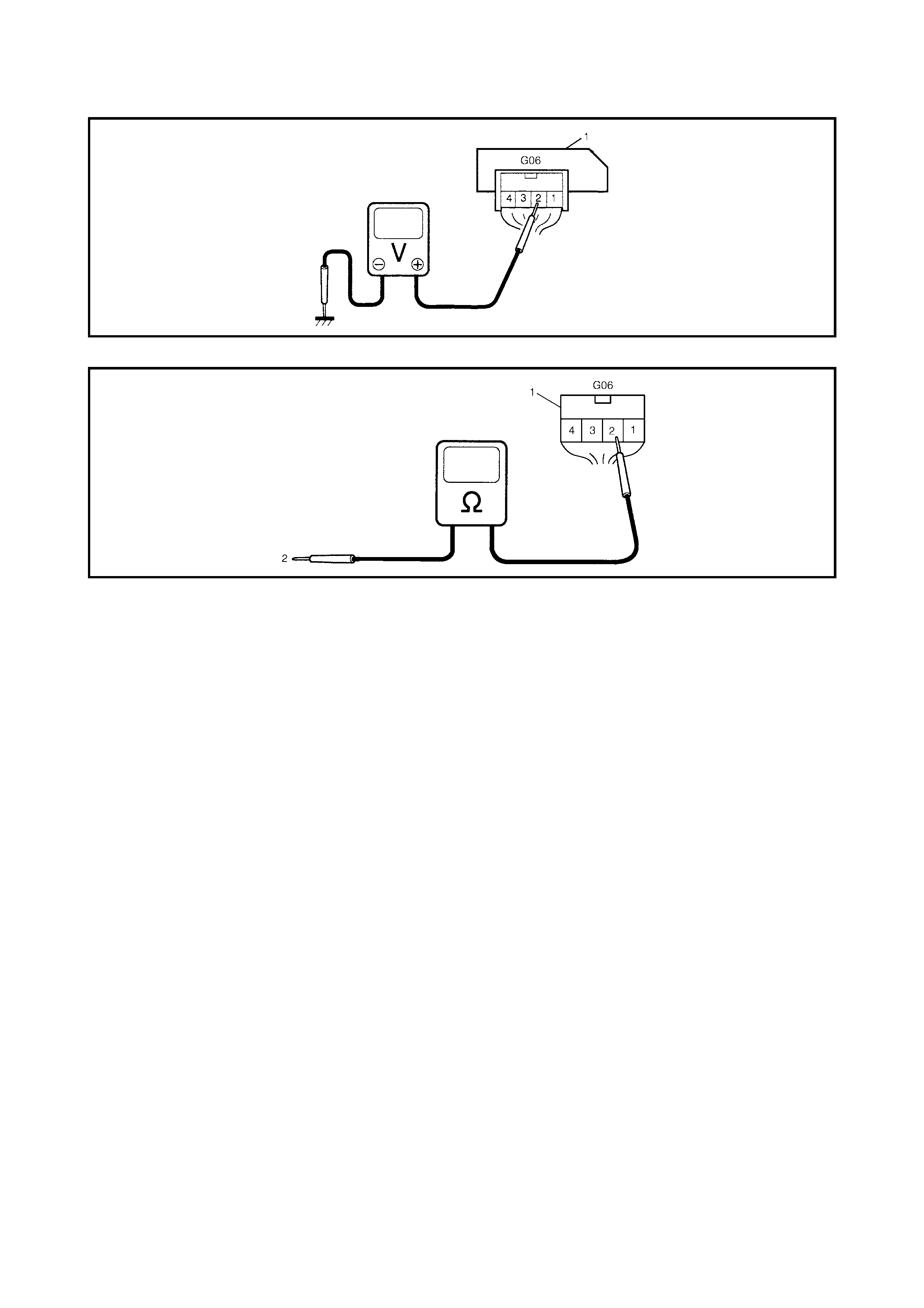
Fig. 1 for Step 1
Fig. 2 for Step 2
Legend
2.18 INSPECTION OF ECM, IMMOBILISER CONTROL MODULE AND ITS CIRCUIT
The ECM, immobil is er con tr ol mo dul e and i ts cir cuit ca n be
checked at the ECM wiring connectors and immobiliser
contro l m odule wiring con nector by measuring the vo ltag e.
Described here is only inspection of the immobiliser control
module. For inspection of the ECM, refer to the Engine &
Emission Control Input/output Table in 1.3 ELECTRONIC
CONTROL SYSTEM in Section 6E1.
CAUTION: The i
mmobiliser control module cannot be
checked by itself. It is strictly prohibited to connect
a voltmeter or ohmmeter to the immobiliser control
module with the connector disconnected.
VO LTAGE CHECK
1. Remove the immobiliser control module from the
steering lock assembly with ignition switch OFF, refer
to 3.3 IMMOBILISER CONTROL MODULE in this
Section.
2. Connect the immobiliser control module connector to
the immobiliser control module.
1. Immobiliser control module connector
2. Connect to serial data link terminal (G02-7) of ECM connector while disconnected
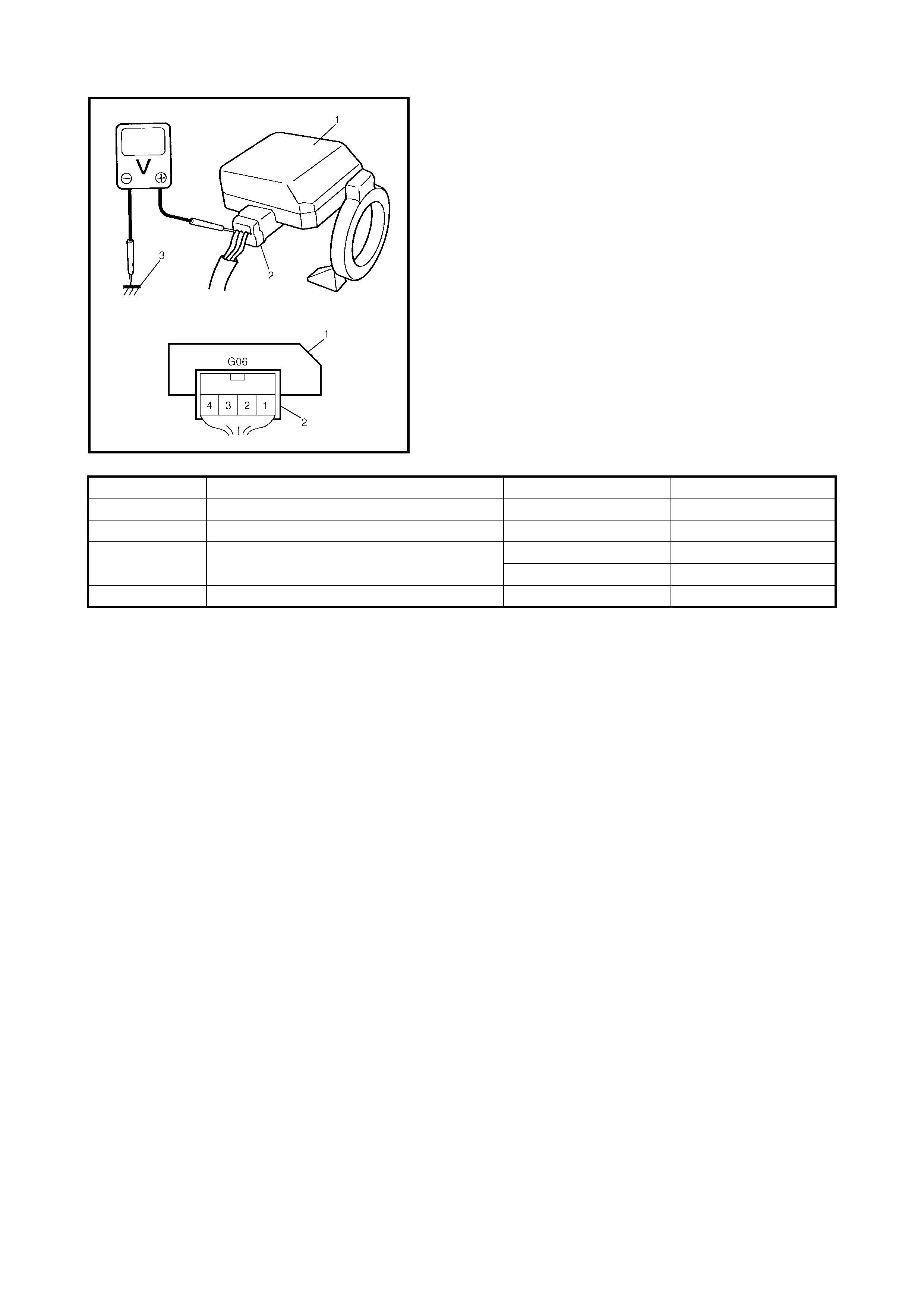
3. Check voltage at each terminal of the immobiliser
control module (1) connector (2) while connected to
ground (3).
NOTE:
As each terminal voltage is affected by the bat-
tery v oltage, con firm th at it is 11V or more w hen ign ition
switch is ON.
TERMINAL CIRCUIT NOMINAL VOLTAGE CONDITION
G06-1 Ground – –
G06-2 Data link connector (Serial data terminal) 4 – 5V Ignition switch ON
G06-3 Ignition signal 10 – 14V Ignition switch ON
0 – 0.8V Ignition switch OFF
G06-4 Power source 10 – 14V Ignition switch ON
3. ON-VEHICLE SERVICE
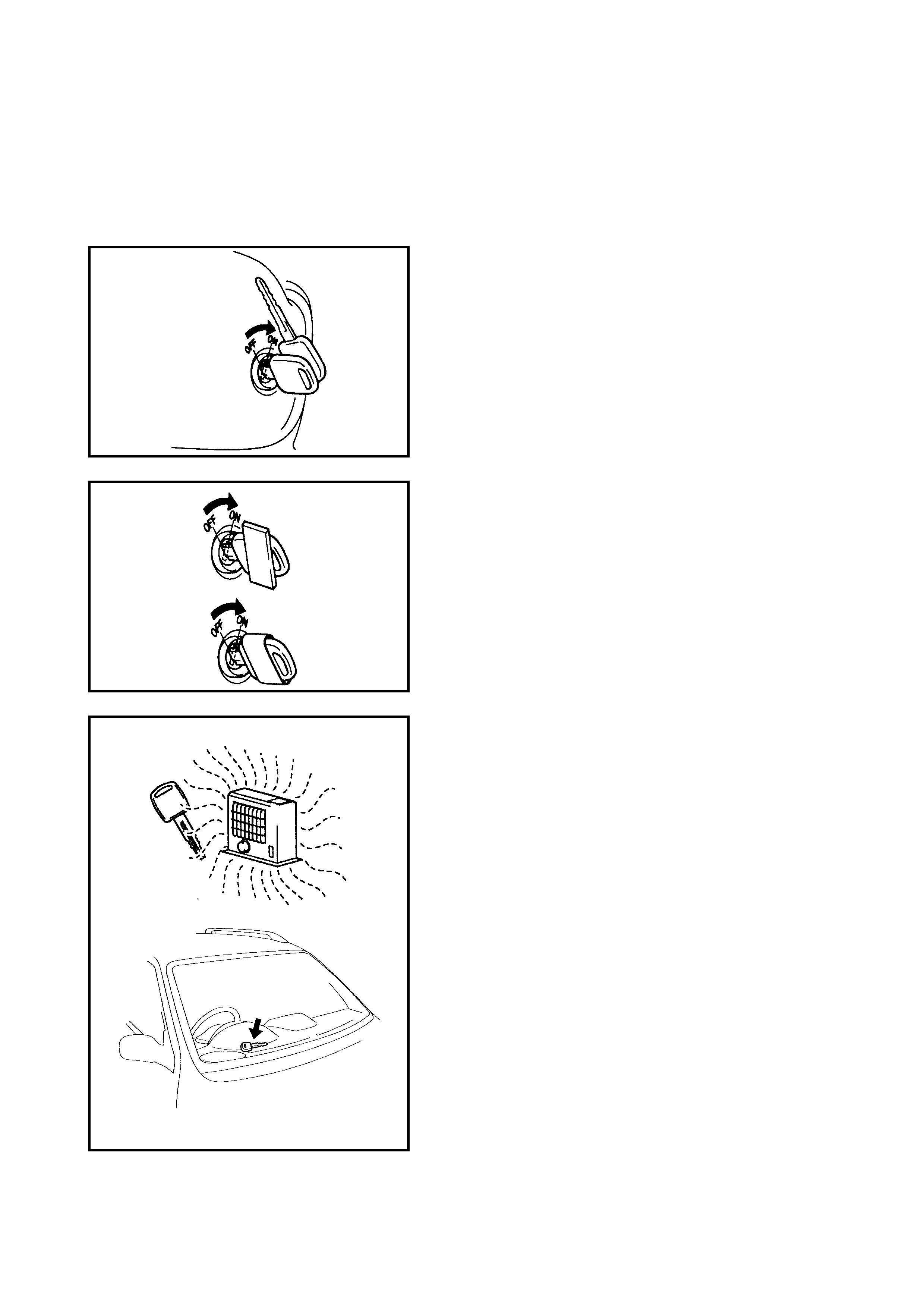
3.1 PRECAUTIONS IN HAND LIN G IMMOBILISER CONTROL SYSTEM
• Don’t turn the ignit ion switch ON while another igni tion
key for the immobiliser control system is placed close
by. The system may dete ct an ab normal con dition and
prevent the engine fr om starting.
• Do not turn the ignition switch ON using an ignition key
that has any type of metal wound around its grip or is in
contact with it. The system may detect an abnormal
condition and prevent the engine from starting.
• Do not leave the ignition key where high temperature is
anticipated. High temperature will cause the transpon-
der in ignition key to malfunction or be damaged.
• Do not turn ignition switch ON with a radio antenna
placed near the immobiliser control module. The sys-
tem may dete ct a n abn or mal co nditio n and prevent th e
engine from starting.
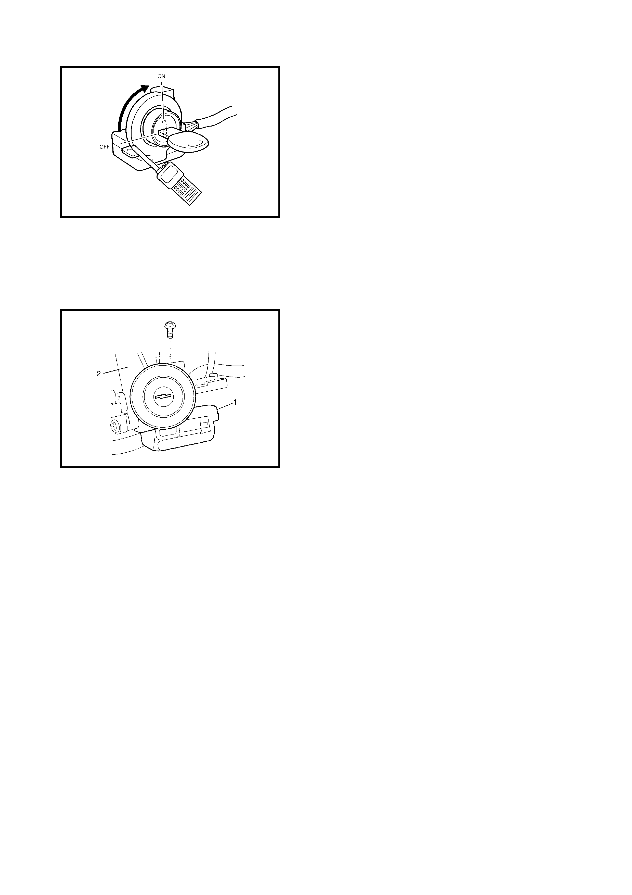
3.2 IMMOBILISER CONTROL MODULE
REMOVAL
1. Disconnect negative (–) cable at the battery.
2. Remove the steering column upper and lower covers.
3. Disconnect the immobiliser control module connector.
4. Remove the immobiliser control module (1) from the
steering lock assembly (2) after tilting the steering
column fully down.
INSTALLATION
Reverse removal procedure for installation.
NOTE:
After replacing the immobiliser control module,
register the transponder code and ECM / immobiliser
control module code in the immobiliser control module
and the ECM / immobiliser control module code in the
ECM, refer to 6. PROCEDURE AFTER IMMOBILISER
CONTROL MODULE REPLACEMENT in this Section.

4. IMMOBILISER FUNCTIONS
F0: DIAGNOSTIC TROUBLE CODES
In this test mode, DTC(s) stored by the Immobiliser Control Module can be displayed . Only one option is pro-
vided:
F0:Read DTC Information As Stored By ECU
As DTCs are stored in the ECM’s volatile memory, a Clear DTC option is not required.
F1: DATA DISPLAY
This mode TECH 2 displays the following data parameter:
Date of ECU Programming
Number of Transponder Keys Programmed.
F2: SNAPSHOT
In th is test mode, the TECH 2 scan tool c aptures data befo re an d after a snapshot trigger ing con ditio n whic h
may or may not set a DTC. The Snapshot mode will help identify problems that may cause intermittent opera-
tion of the Immobiliser system.
F3: ADDITIONAL FUNCTIONS
In this test mode, one additional operation may be carried out on the Immobiliser system.
The following operation can be performed:
F0: Erase Transponder Keys
F4: PROGRAMMING
This mode allows the programming of replacement or additional components to the Immobiliser system.
F0: Program Immobiliser
F1: Program Transponder Key
NOTE:
• Up to four transponder key codes can be registered.
• It is not possib le to register a trans ponder co de for an ignition ke y that is already reg istered in the imm obil-
iser control module.
5. HOW TO REGISTER IGNITION KEY
Register the ignition key with built-in transponder in the immobiliser control module by using the following pro-
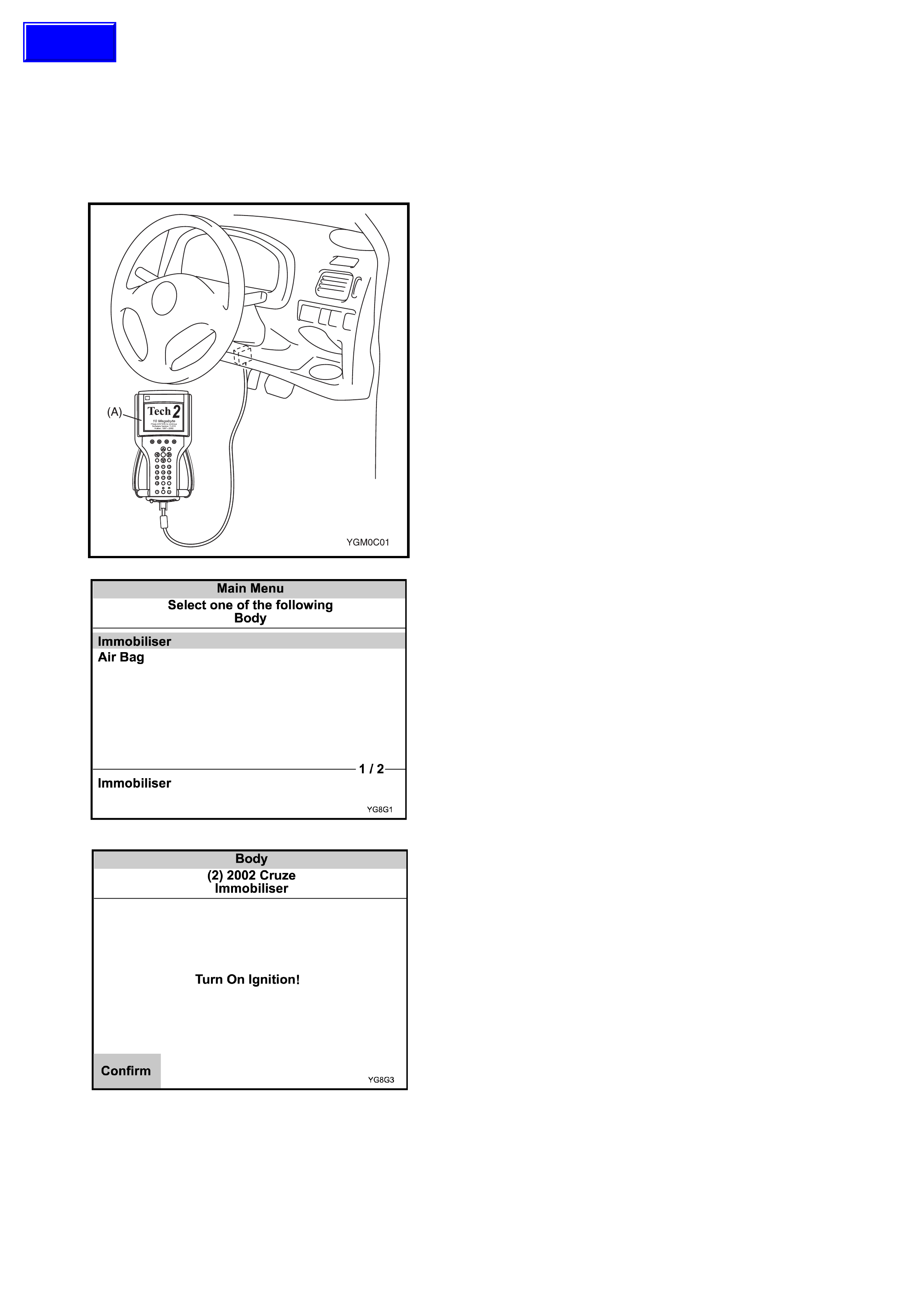
cedure. 1. With the i gnitio n swit ch OF F, con nect Te ch 2 (A ) to the
data link connector (DLC) (1) located on underside of
instrument panel at driver’s seat side.
•NOTE: Refer to Section 0C for complete information
on connecting TECH 2 to the vehicle and navigation
through the initial screens.
I
1. Select the correct body system from the Vehicle
Identification menu with the arrow keys, then press
ENTER and follow the instructions on the screen.
2. Turn on the ignition and press the Confirm soft key.
Techline
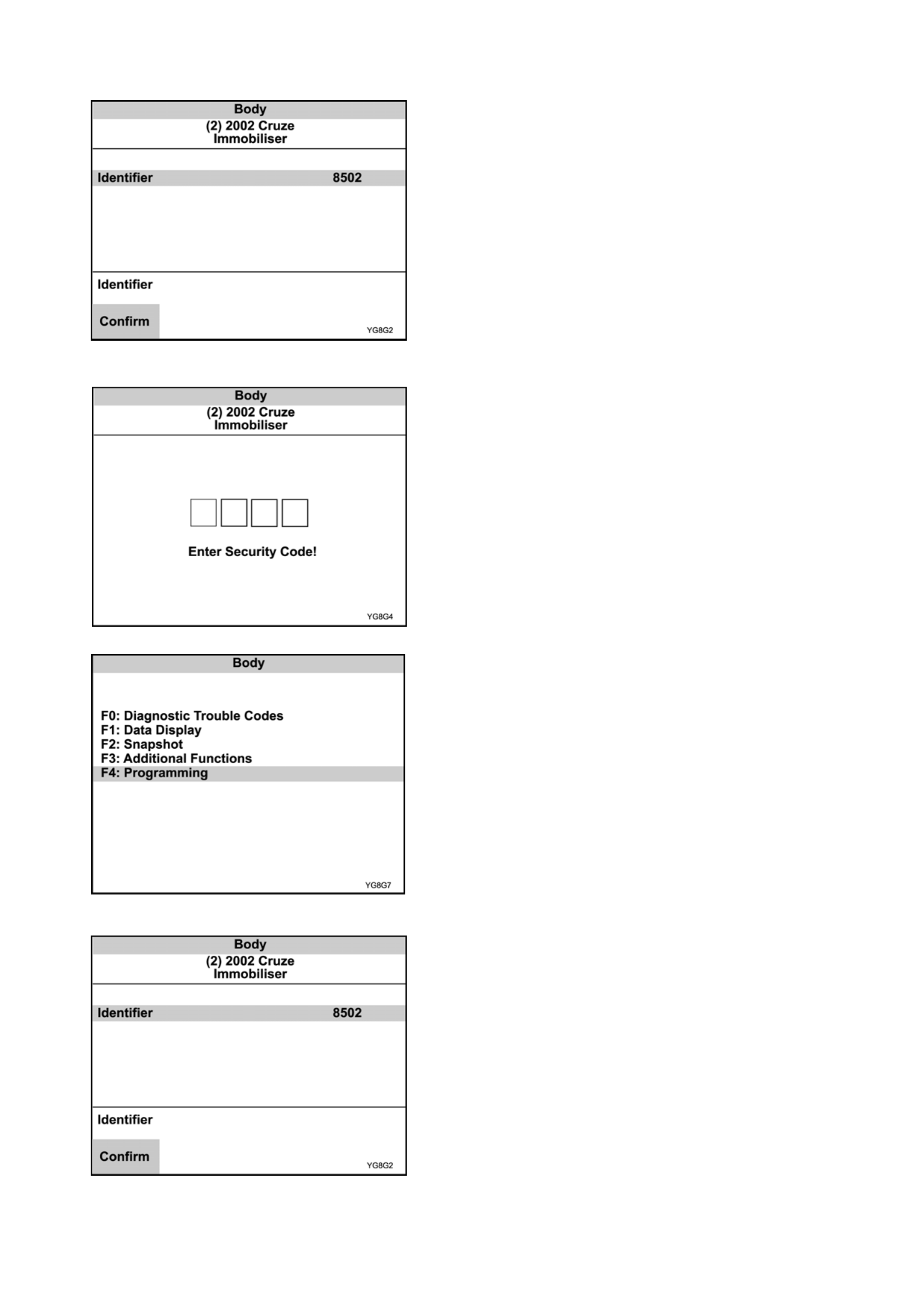
1. The System identification screen will then display the
control module Part number and System type.
Press the Confirm soft key.
2. The Security Screen will then be displayed. Enter the
4 digit securi ty num ber 089 5 usi ng the TECH 2 keypa d
Note: 0895 is used for ALL YG Cruze vehicles.
Confirm the security number when prompted, then follow
the On-screen instructions.
3. Select F4:Programming / F1:Program Immobiliser,
then follow the On-screen instructions.
4. The System identification screen will then display the
control module Part number and System type.
Press the Confirm soft key.
6. PROCEDURE AFTER IMMOBILISER CONTROL MODULE &/OR
ENGINE CONTROL UNIT REPLACEMENT
When an i mmobili ser control mod ule is re placed, in cluding rep lacement due to recheck ing by using a known
good immobiliser control module during trouble diagnosis, register the transponder code and the ECM /
immobiliser control module code in the immobiliser control module by performing the following procedure.
NOTE: The transponder Keys MUST be programmed to the ICM prior to carrying out the ICM registra-
tion procedure.
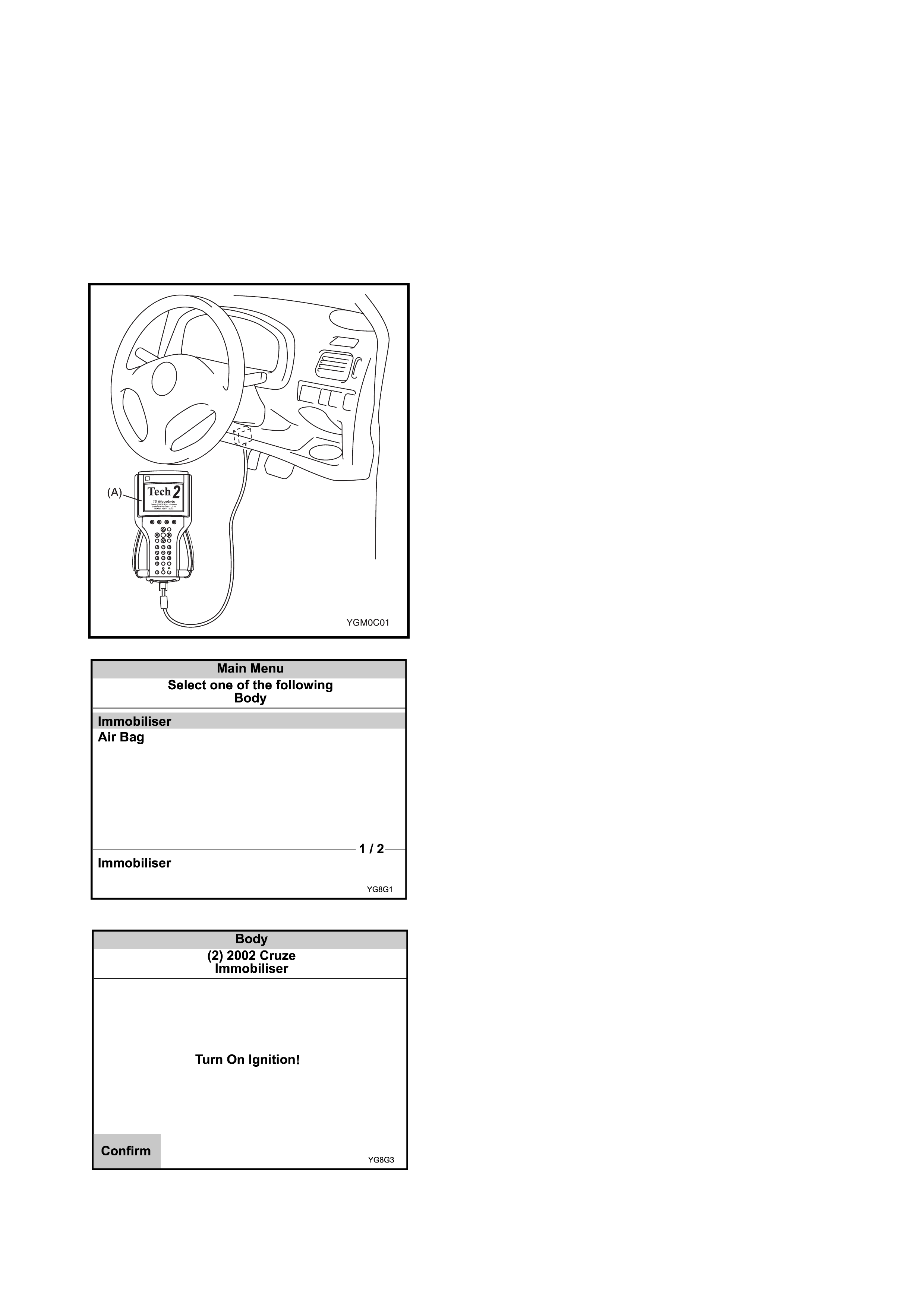
1. With the i gnitio n swit ch OF F, con nect Te ch 2 (A ) to the
data link connector (DLC) (1) located on underside of
instrument panel at driver’s seat side.
•NOTE: Refer to Section 0C for complete information
on connecting TECH 2 to the vehicle and navigation
through the initial screens.
I
1. Select the correct body system from the Vehicle
Identification menu with the arrow keys, then press
ENTER and follow the instructions on the screen.
2. Turn on the ignition and press the Confirm soft key.
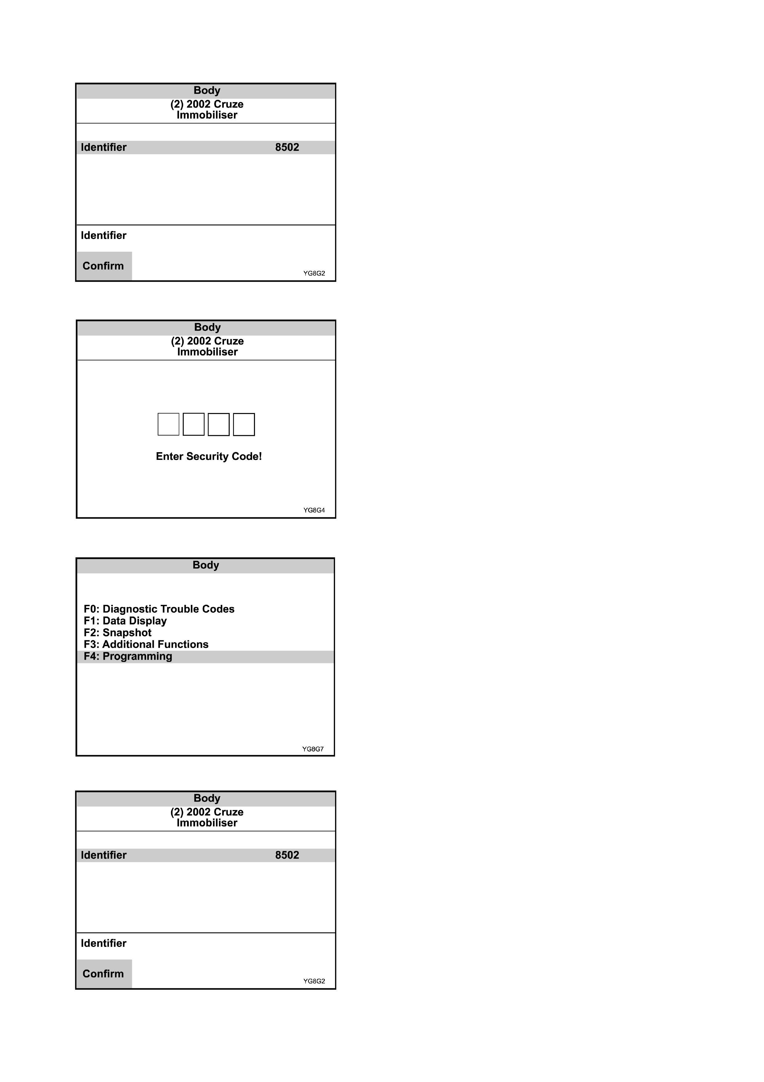
3. The System identification screen will then display the
control module Part number and System type.
Press the Confirm soft key.
4. The Security Screen will then be displayed. Enter the
4 digit securi ty num ber 089 5 usi ng the TECH 2 keypad
Note: 0895 is used for ALL MY2002 YG Cruze
vehicles.
Confirm the security number when prompted, then follow
the On-screen instructions.
5. Select F4:Programming / F1:Program Immobiliser,
then follow the On-screen instructions.
6. The System identification screen will then display the
control module Part number and System type.
Press the Confirm soft key.
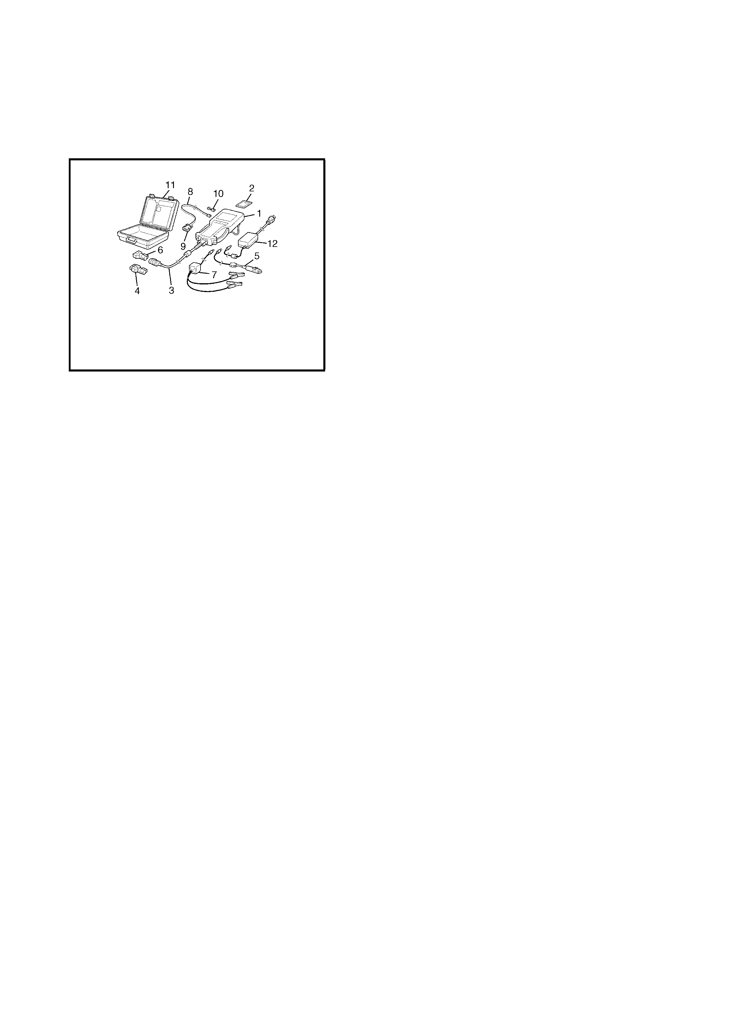
7. SPECIAL TOOLS
NOTE: Refer to Section 0A GENERAL INFORMATION – 7. CONSOLIDATED TOOLS for a detailed list of
special tools and the local equivalent if one is available.
NOTE: This kit includes the following items:
1.Tech 2,
2.PCM C IA ca rd ,
3.DLC cable,
4.SAE 16 /19 adapter,
5.Ciga rette cab le ,
6.DLC loopback adapter,
7.Battery power cable,
8.RS232 cable,
9.RS232 adapter,
10.RS232 loopback connector,
11.Storage case,
12.Power supply.
Tech 2 kit.
See NOTE.