
SECTION 9 - BODY SERVICE
1. GLASS, WINDOWS AND MIRRORS
1.1 FRONT DOOR GLASS
Removal
Installation
1.2 FRONT DOOR WINDOW REGULATOR
Removal
Inspection
Installation
1.3 DOOR MIRROR
Removal
Installation
1.4 REAR DOOR GLASS
Removal
Installation
1.5 REAR DOOR WINDOW REGULATOR
Removal
Inspection
Installation
1.6 WINDSHIELD
Removal
Installation
1.7 QUARTER WINDOW
Removal and Installation
1.8 BACK DOOR GLASS
Removal and Installation
2. BODY STRUCTURE
2.1 FRONT DOOR ASSEMBLY
Removal
Installation
2.2 REAR DOOR ASSEMBLY
Removal and Installation
2.3 BACK DOOR ASSEMBLY
Removal
Installation
2.4 HOOD
Removal
Installation
Adjustment
Inspection
2.5 FRONT BUMPER SIDE EXTENSION
Removal
Installation
2.6 FRONT BUMPER CENTRE EXTENSION
Removal
Installation
WARNING:
For vehicles equipped with Supplemental Restraint (Airbag) System:
• Service on and around the airbag system components or wiring must be performed only by an
authorised HOLDEN retailer. Refer to AIRBAG SYSTEM COMPONENTS and WIRING LOCATION
VIEW under GENERAL DESCRIPTION in Section 10B AIRBAG SYSTEM in order to confirm
whether you are performing service on or near the airbag system components or wiring. Please
observe all WARNINGS and SERVICE PRECAUTIONS under ON-VEHICLE SERVICE in Section 10B
AIRBAG SYSTEM before performing service on or around the airbag system components or wir-
ing. Failure to follow WARNINGS could result in unintentional activation of the system or could
render the system inoperative. Either of these two conditions may result in severe injury.
• Technical service work must be started at least 90 seconds after the ignition switch is turned to
the “LOCK” position and the negative cable is disconnected from the battery. Otherwise, the sys-
tem may be activated by reserve energy in the Sensing and Diagnostic Module (SDM).
• When body servicing, if shock may be applied to airbag system component parts, remove those
parts beforehand. (Refer to Section 10B AIRBAG SYSTEM.)
NOTE:
Fasteners are important attaching parts in that they could affect the performance of vital compo-
nents and systems, and / or could result in major repair expense. They must be replaced with one of
the same part number of with an equivalent part if replacement becomes necessary.
Do not use a replacement part of lesser quality or substitute a design. Torque values must be used
as specified during reassembly to assure proper retention of these parts.
Techline

2.7 SILL PANEL EXTENSION
Removal
Installation
2.8 FRONT FENDER EXTENSION
Removal
Installation
2.9 REAR FENDER EXTENSION
Removal
Installation
2.10 REAR BUMPER CENTRE EXTENSION
Removal
Installation
2.11 REAR BUMPER SIDE EXTENSION
Removal
Installation
2.12 FRONT BUMPER
Removal
Disassemble
Installation
2.13 REAR BUMPER
Removal
Disassemble
Installation
2.14 FRONT FENDER
Removal
Installation
2.15 ROOF RAILS
Removal
Installation
2.16 BODY DIMENSIONS
Engine Room
Back Door
Side Body
Under Body
2.17 PANEL CLEARANCE
3. INSTRUMENTATION AND DRIVER
INFORMATION
3.1 INSTRUMENT PANEL
Removal
Installation
4. SEATS
4.1 FRONT SEAT
Removal
Installation
4.2 REAR SEAT
Removal
Installation
5. SECURITY AND LOCKS
5.1 FRONT DOOR LOCK ASSEMBLY
Removal
Installation
Inspection
5.2 REAR DOOR LOCK ASSEMBLY
Removal
Installation
5.3 BACK DOOR LOCK ASSEMBLY
Removal
Installation
Inspection
5.4 KEY CODING
Key Usage and Identification
Ignition Switch Cylinder Lock
Removal and Install atio n
Electrical Diagnosis
6. EXTERIOR AND INTERIOR TRIM
6.1 FLOOR CARPET
Removal
Installation
6.2 HEADLINING
Removal
Installation
7. PAINT AND COATINGS
7.1 ANTI-CORROSION TREATMENT
7.2 SEALANT APPLICATION AREAS
7.3 UNDER COATING APPLICATION AREAS
7.4 ANTI-CORROSION COMPOUND
APPLICATION AREA
Plastic Par t s Finishing
Painting
Reference
8. REQUIRED SERVICE MATERIAL
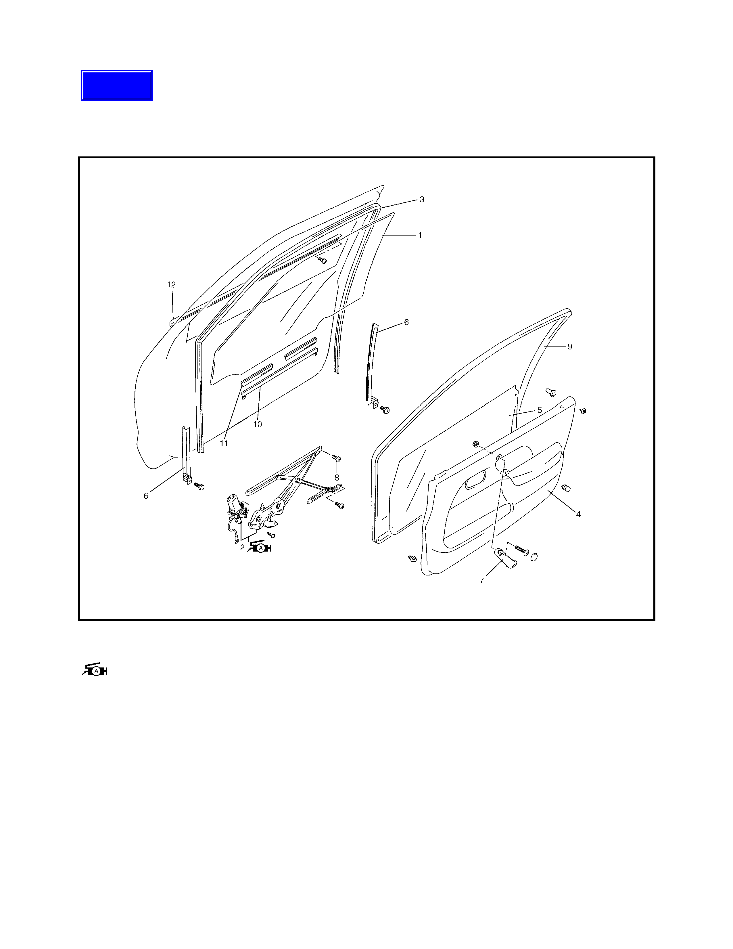
1. GLASS, WINDOWS AND MIRRORS
1.1 FRONT DOOR GLASS
Legend 1. Door glass 5. Door sealing cover 10. Glass bottom channel
2. Window regulator assembly
: Apply Lithium grease
to sliding part
6. Door sash 11. Glass bottom rubber
7. Front door grip 12. Front door outer
weather-strip
8. Bottom channel attaching
screw
3. Glass weather-strip channel
4. Door trim 9. Door opening weather-strip
Techline
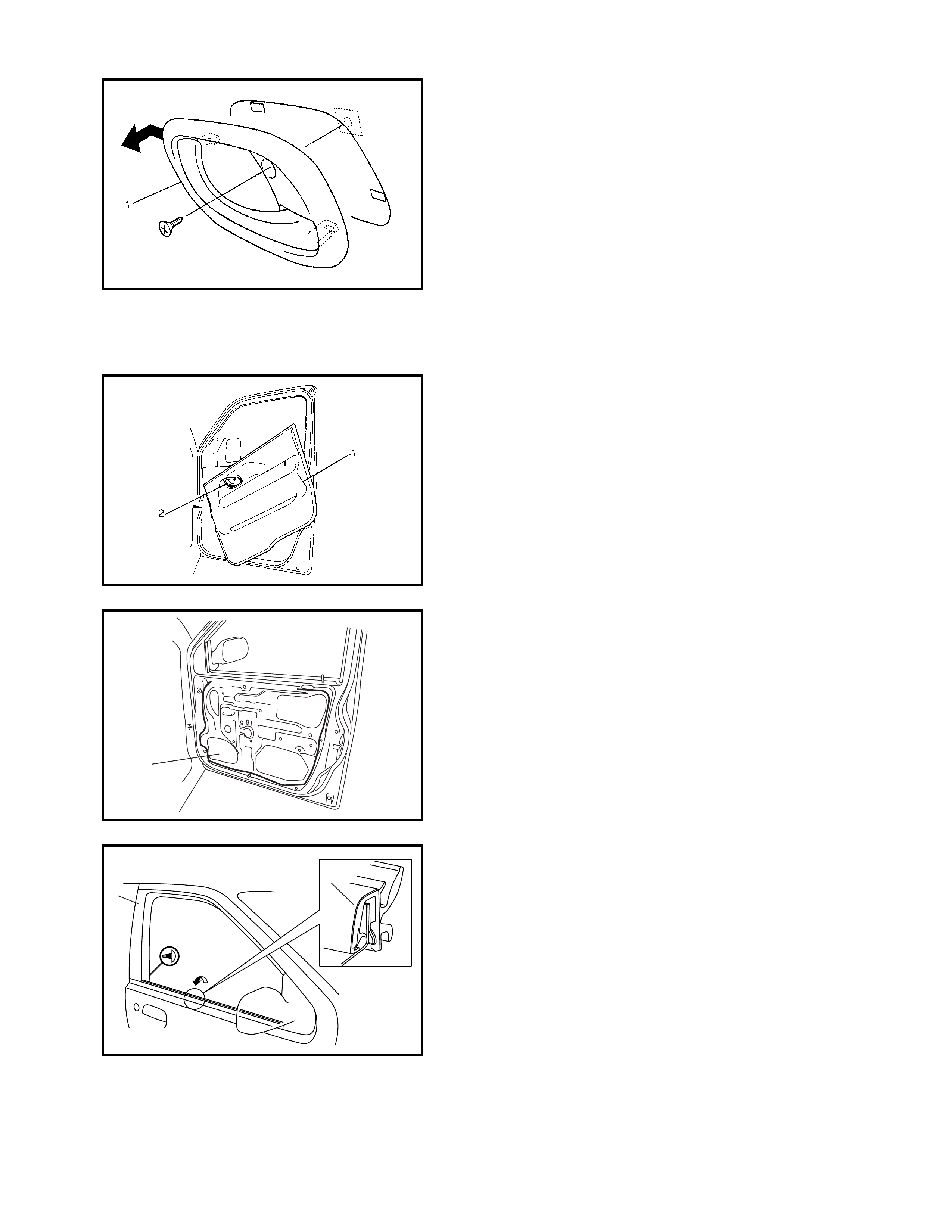
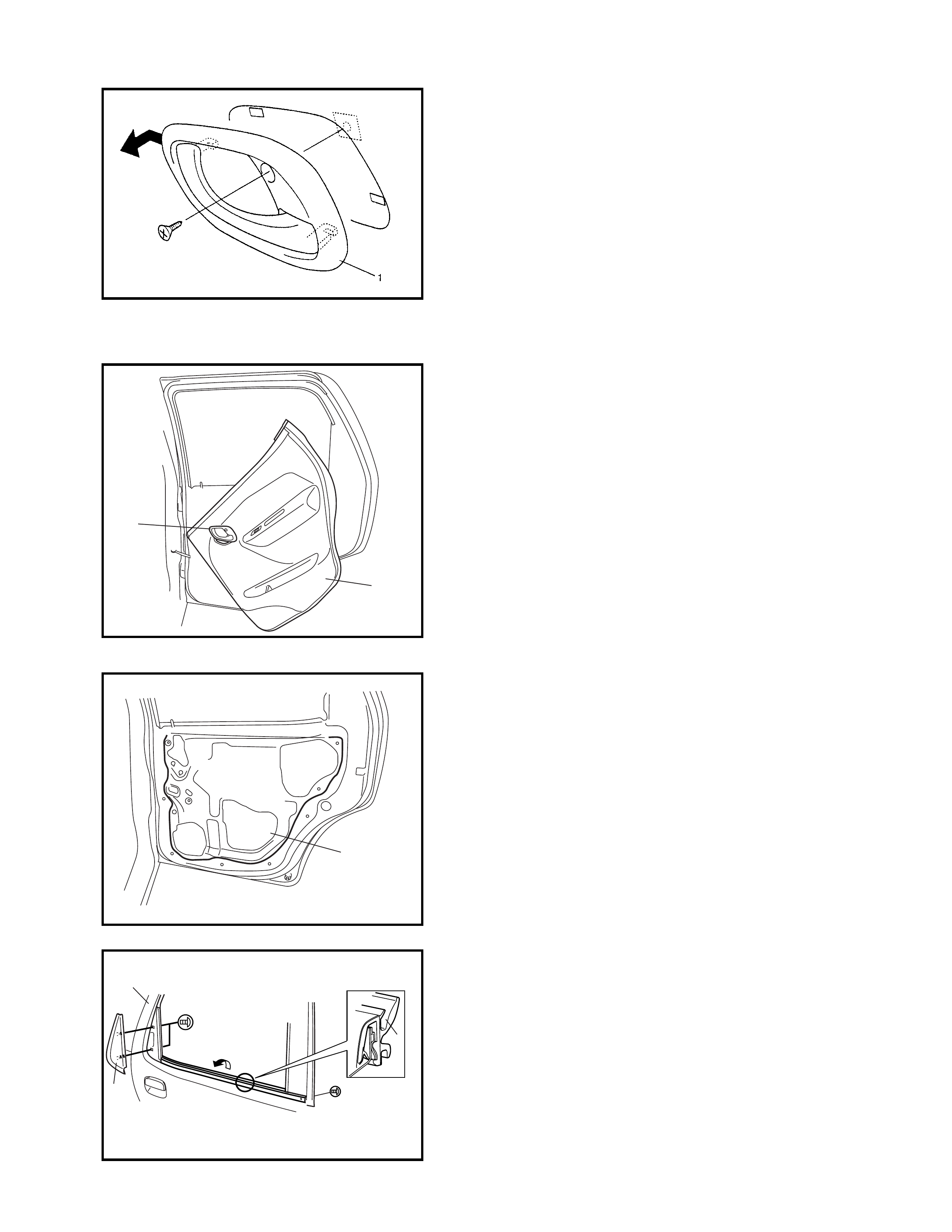
REMOVAL
1. Remove the inside handle bezel (1).
2. Remove the inside door grip.
3. Remove the mirror inner garnish.
Refer to 1.3 DOOR MIRROR in this Section.
4. Remove the door trim (1).
• Remove retainer (2) and unclip from trim from door
panel.
• With the inside handle bezel (2) tilted as shown, turn
the door trim (1) 90° counterclockwise to remove it.
Disconne ct the power window s witch lead wire at c on-
nector.
5. Remove the door sealing cover (1).
6. Remove the door mirror.
Refer to 1.3 DOOR MIRROR in this Section.
7. Remove the outer weather-strip (1).
8. Lower the window all the way down.
9. Use a tape-protected putty-knife to pry off the outer
weather-strip (1).
NOTE: Take care not to deform the outer weather-strip (1)
when removing from door panel (2).
1
1
2
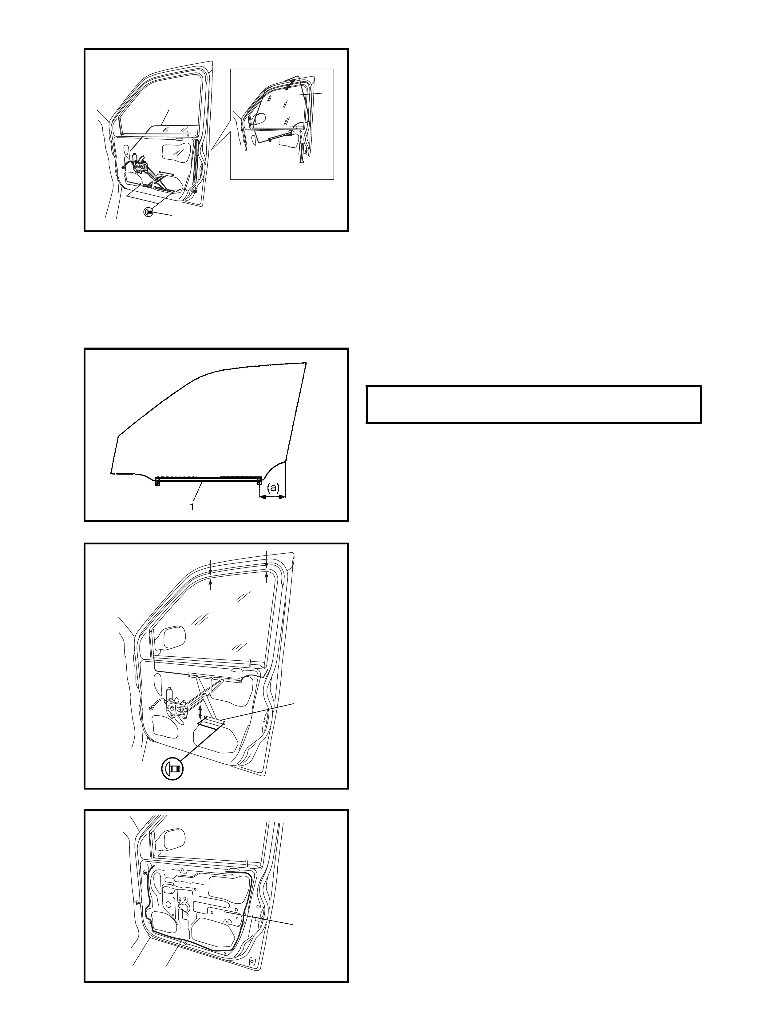
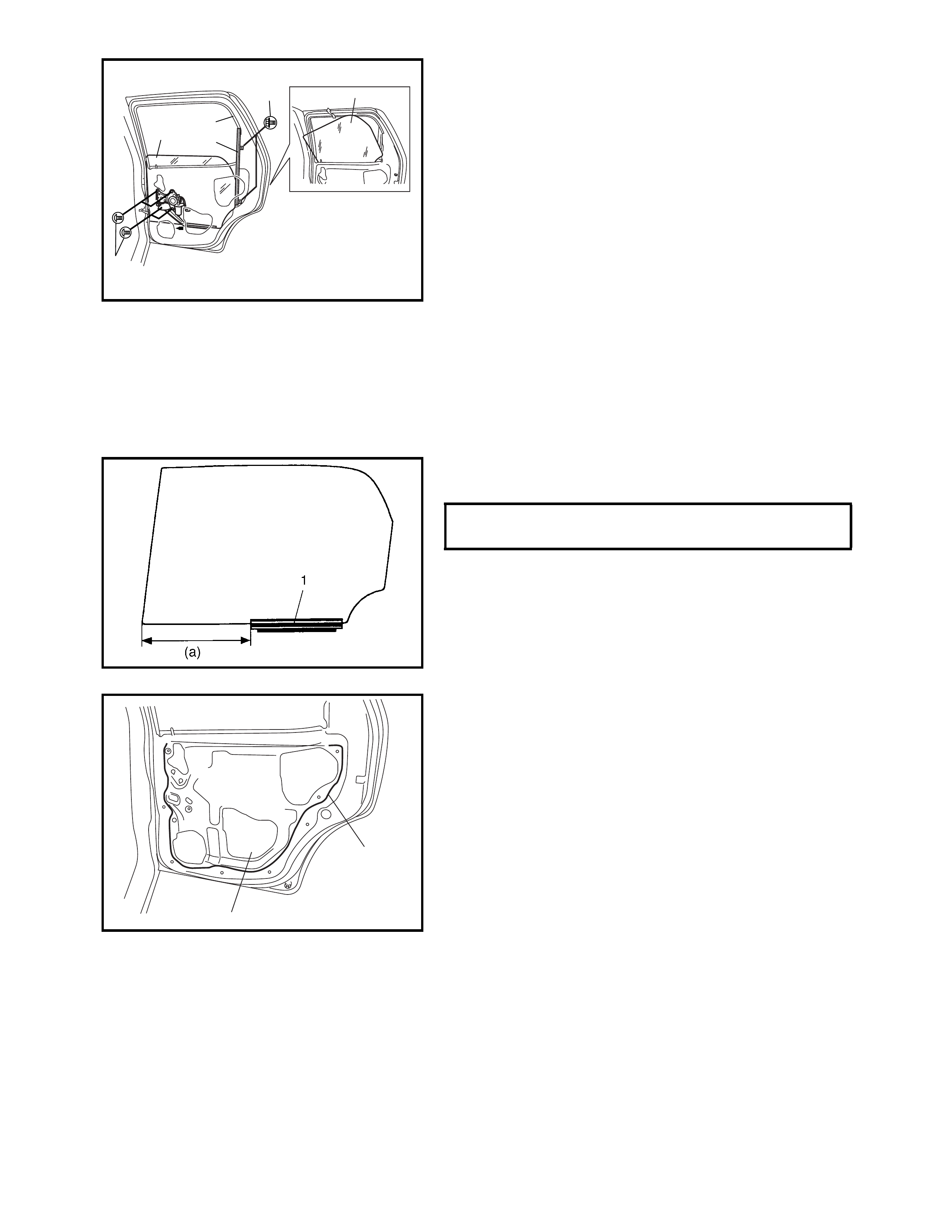
10. Remove bottom channel attaching screws (1).
11. Turn door glass (2) 90° counterclockwise to remove.
INSTALLATION
Reverse r emoval pr ocedure to i nstall door glass noting the
following instructions.
• If glass weather-strip channel is deformed, replace it.
• Tighten the bottom channel attaching screws, the rear
screw first followed by the front screw.
• Fit door glass into bottom channel (1) in the correct
position as shown in figure.
• Adjust window regulator equaliser (1) so that measure-
ment (a) and (b) are equal.
• Secure door sealing cover (1) with adhesive (2).
2
2
1
DOOR GLASS POSITION IN BOTTOM
CHANNEL (a) 90.6 - 93.8 mm
1
(a) (b)
1
2
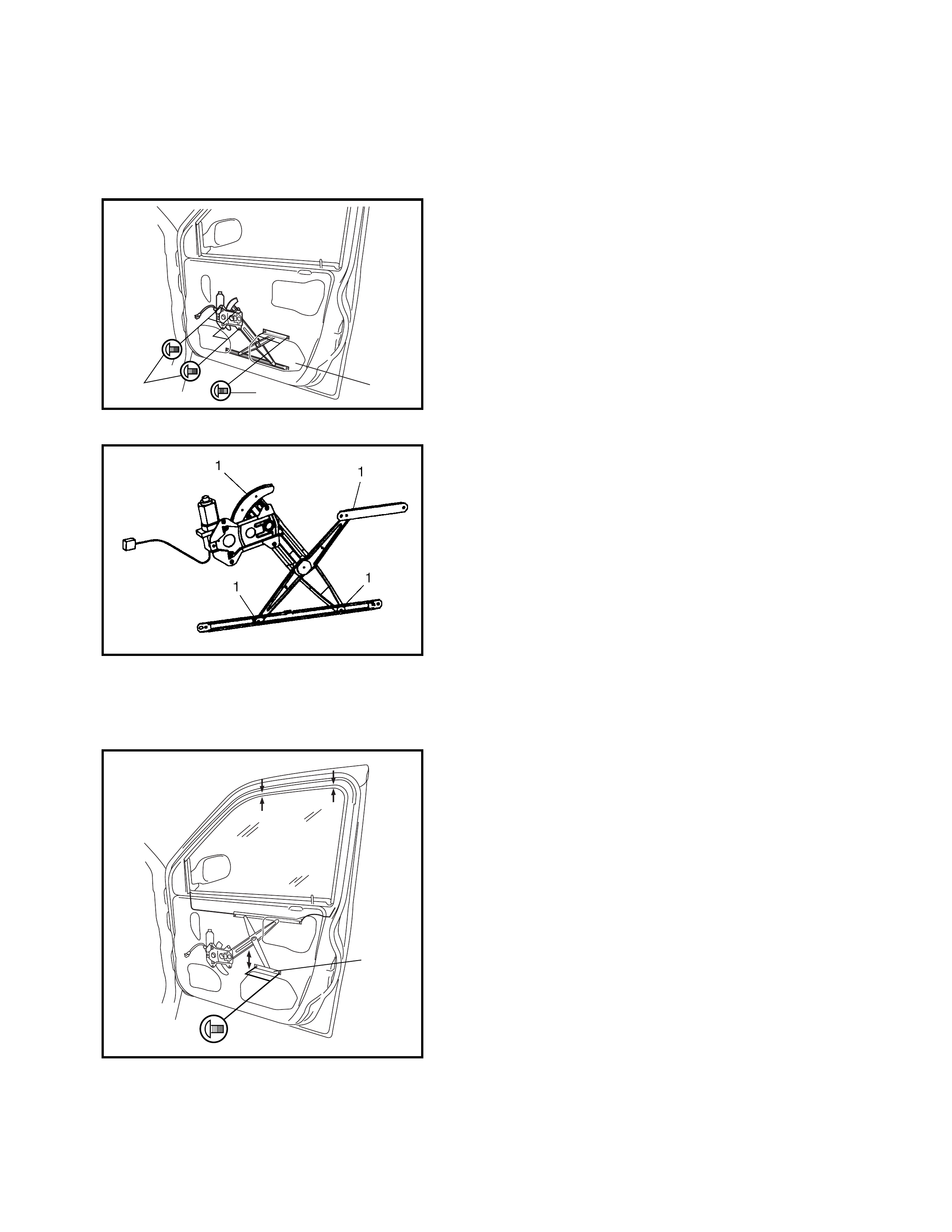
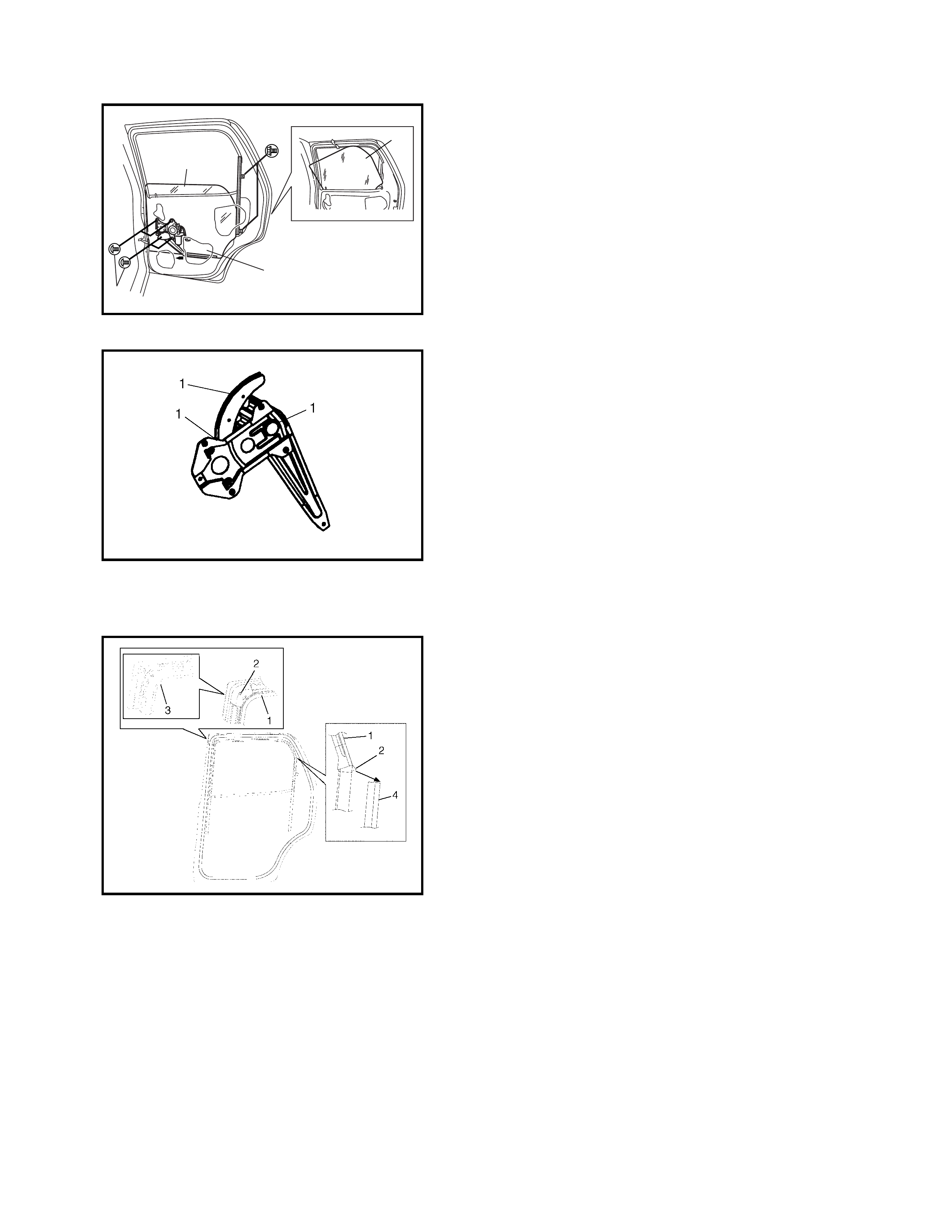
1.2 FRONT DOOR WINDOW REGULATOR
REMOVAL
1. Remove the door glass, refer to 1.1, FRONT DOOR
GLASS in this Section.
2. Disconnect the power window motor lead wire at the
connector and loosen clamp.
3. Loosen the regulator m ounting screws (1) and remove
the regulator through the hole (2) as shown in figure.
INSPECTION
Check the following parts :
• Check regulator sliding and rotating parts for
grease (1).
• Check rollers for wear and damage.
Replace if excessively worn.
INSTALLATION
Reverse r emoval pro cedure to install the win dow regulator
noting the following:
• When installing the door glass, check that the top of
the glass contacts the glass weather-strip channel
evenly and that the glass moves up and down
smoothly.
If the door glass is angled when refitted, adjust the win-
dow regulator equaliser (1) so that measurements (a)
and (b) are equal.
112
1
(a) (b)
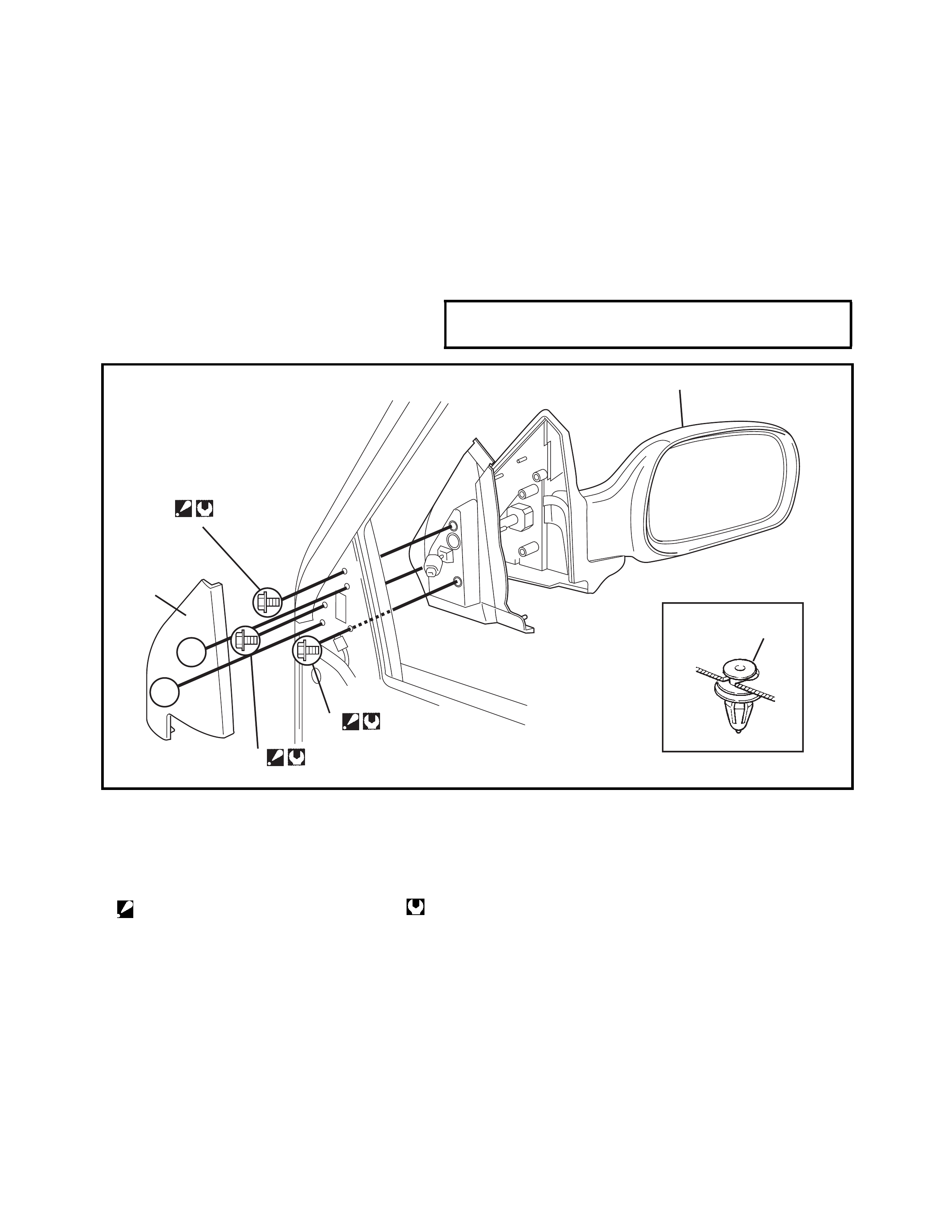
1.3 DOOR MIRROR
REMOVAL
1. Lower the window and ensure the ignition switch is in
the OFF position.
2. Carefully unclip (3) the inner mirror garnish (2) and
unplug electrical connector.
3. Support the door mirror, remove screws (a,b,c) and
carefully lift the door mirror away from the door.
INSTALLATION
Reverse removal procedure to install the door mirror noting
the tightening sequence of screws (a,b,c).
Legend
DOOR MIRROR MOUNTING SCREWS
TORQUE SPECIFICATION 4.5 Nm
a4.5 Nm
c4.5 Nm
4.5 Nm
b
2
2
3
[A]
[A]
[A]
1. Door mirror a. Mirror mount screw .
2. Inner garnish b. Mirror mount screw
3. Clip c. Mirror mount screw
Tighteni ng order : a → b → c Tightening torque

1.4 REAR DOOR GLASS
Legend
1. Door glass 5. Door sealing cover 9. Rear door inner garnish
2. Window regulator assembly
: Apply Lithium grease
to moving section.
6. Door sash 10. Rear door outer garnish
7. Rear door outer 11. Glass bottom channel
weath er-s tr ip 12. Glass bott om rub ber
3. Glass weather-strip channel 8. Rear door inside pull 13. Door inside pull
4. Door trim handle bracket handle case
REMOVAL
1. Remove the inside handle bezel (1).
2. Remove the door inside pull handle case fitting screw.
3. Remove the rear door inner garnish.
4. Remove the door trim (1).
With the inside handle bezel (2) tilted as shown, turn
the door trim 90° counterclockwise to remove it.
Disconnect the power window switch lead wire at the
connector.
5. Remove the door inside pull handle bracket.
6. Remove the door sealing cover (1).
7. Remove the rear door outer garnish (1).
8. Remove the outer weather-strip (2).
9. Lower the window all the way down.
10. Use a tape-protected putty knife (or screwdriver) to pry
off the outer weather-strip.
NOTE: Take care not to deform the outer weather-strip (2)
when removing from door panel (3).
2
1
1
2
3
1
11. Detach rear part o f the gla ss weather -strip chan nel (1)
from the sash (2). Remove the sash retaining screws
(3) and remove the sash (2).
12. Loosen the window regulator mounting screws (5).
13. Turn the door glass (4) 90° counterclockwise to
remove.
INSTALLATION
Reverse the removal procedure to install door gl ass notin g
the following:
• If the gla ss weathe r-strip cha nnel is deforme d, replace
it.
• Tighten the bottom channel attaching screws, the rear
screw first followed by the front screw.
• Fit the door glass into the bottom channel (1) in the
correct position as shown in figure.
• Secure the door sealing cover (1) with adhesive (2).
4
1
2
3
5
4
FITTING POSITION OF GLASS IN
BOTTOM CHANNEL (a) 201.9 - 204.9 mm
1
2
1.5 REAR DOOR WINDOW REGULATOR
REMOVAL
1. Remove the rear door glass (3), refer to 1.4 REAR
DOOR GLASS in this Section.
2. Loosen the regulator mounting screws (1) and take out
the regulator through the hole (2) as shown.
INSPECTION
Check the following points:
• Check the regulator sliding and rotating parts for
grease (1).
• Check the rollers for wear and damage
Replace if excessively worn.
INSTALLATION
Reverse r emoval pro cedure to install the win dow regulator
noting the following:
• When the glass weather-strip channel (1) is installed,
fit the glass weather-strip channel convex part (2) to
the door panel cut part (3) and door sash (4).
3
3
2
1
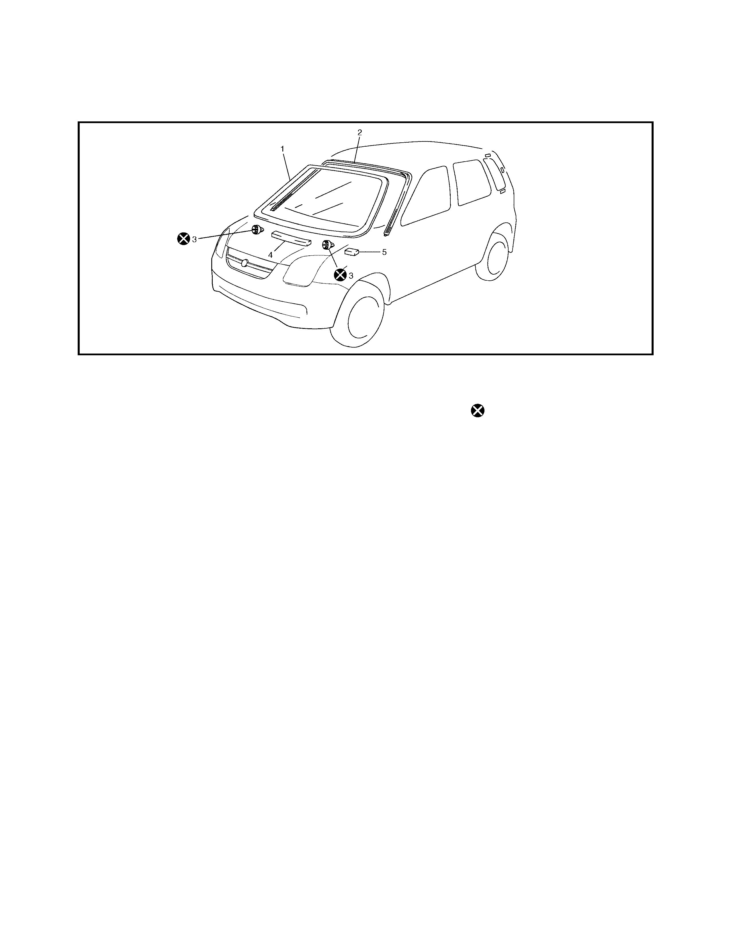
1.6 WINDSHIELD
The front windshield is installed using one component urethane adhesive and primer. When replacing the
windshield it is important to follow the correct procedures and use an approved adhesive which provides suffi-
cient adhe si on strength.
Legend
Caution:
• This section describes the glass replacement using 3 types of primers and 1 type of adhesive.
When using primer and adhesive, be sure to refer to handling instructions supplied by the adhe-
sive manufacturer. Negligence in following the correct procedure or misuse of the adhesive in any
way hinders its inherent adhesive property. Therefore, before beginning work, be sure to carefully
read the instructions and descriptions given by the manufacturer of the adhesive to be used and
to follow the procedure and observe all precautions.
• Should a coated surface be scratched or otherwise damaged, repair the damaged section to avoid
the onset of corrosion.
Use an adhesive of above mentioned type which has the following property.
Glass adhesive shearing strength
: 40 kg / cm2 or more.
Adhesive materials and tools required for removal and installation.
• One component urethane adhesive and primers used in combination (For each windshield replacement).
- Adhesive (470 g)
- Primer for glass (30 g)
- Primer for body (30 g)
- Primer for moulding (30 g)
• Piano string
• Needle punch
• Win ds hie ld kn ife
• Brush for primer application (x 2)
•Knife
• Suction cups
• Sealant gun (for filling adhesive)
• Putty spatula (for correcting adhered parts)
1. Winds hie ld gla ss 3. Stopp er 5. Side spacer
2. Windshield moulding 4. Centre spacer Do not reuse.
REMOVAL
1. Clean both inside and outside of the glass and sur-
rounds.
2. Remove the wiper arms and garnish.
3. Using tape, cover the body surface around the glass to
prevent any damage.
4. Remove the rear view mirror, sunvisor, and front pillar
trims (right & left).
5. If necessary, remove the instrument panel. Refer to
3.1 INSTRUMENT PANEL in this Section.
6. If necessary, remove the headlining. Refer to
6.2 HEADLINING in this Section.
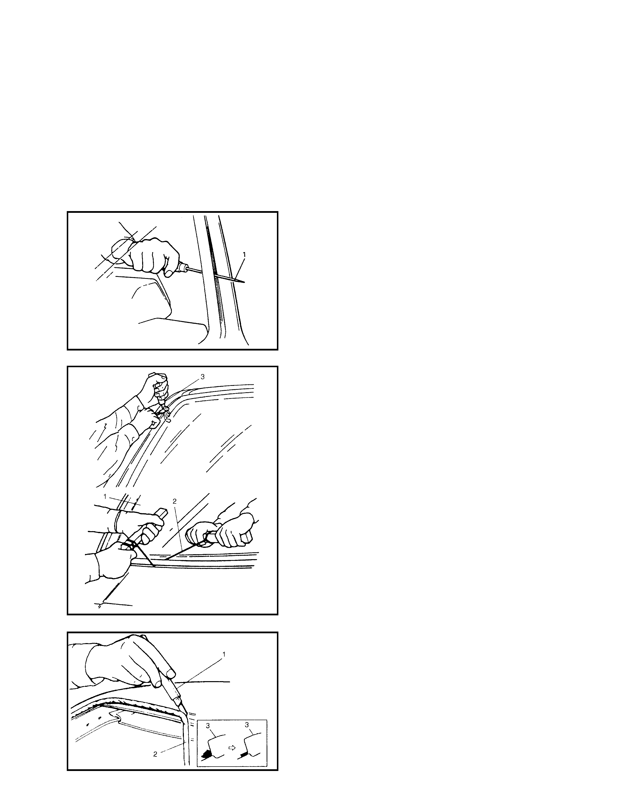
7. Remove (or cut) the windshield moulding.
8. Carefully make a hole through the adhesive with a
needle punch (1) and pass piano string through it.
9. Cut adhesive all around the windshield (1) with piano
wire (2). When using a windshield knife (3) to cut
adhesive, take care not to damage windshield. Use
piano wire to cut adhesive along lower part of wind-
shield.
NOTE: Use the piano wire (2) as close to glass as possible
to prevent damage to the body and instrument panel.
10. Using a knife (1), tidy excess adhesive (2) remaining
on body side (3) so that it is 1 to 2 mm thick around
windsh ie ld open in g.
NOTE: Before us ing knife (1), cl ean it with alcoho l or simi-
lar to remove oil.
11. When reusing windshield, remove the remaining
adhesive (1), taking care not to damage the primer
coated surface (2).
INSTALLATION
1. Clean the windshield edge where windshield glass is to
adhere with cleaning solvent. (Allow to dry for at least
10 minutes.)
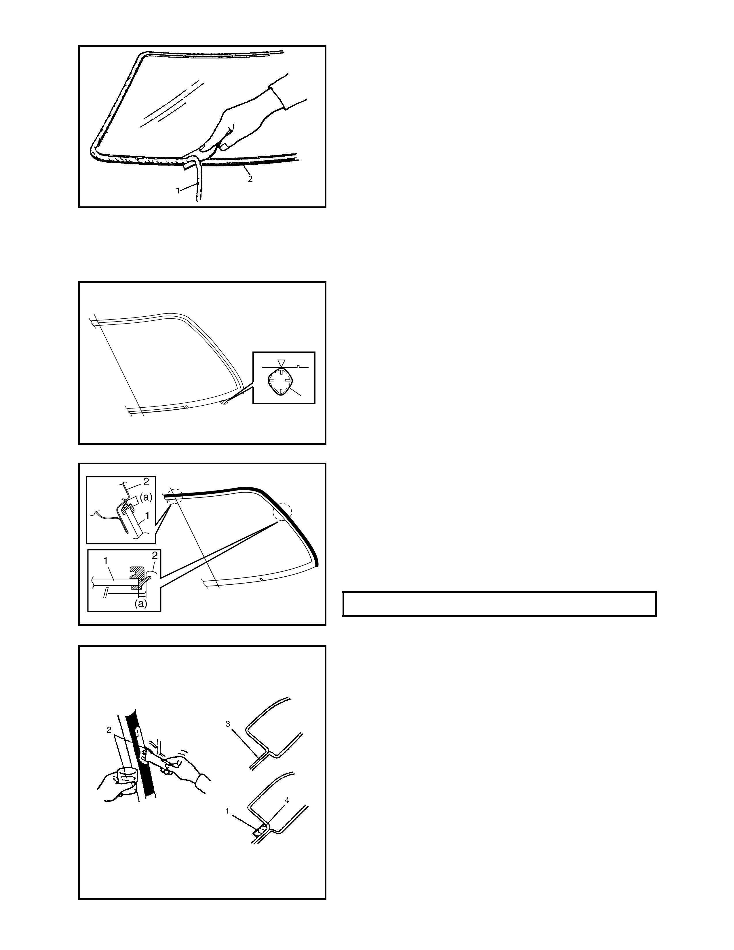
2. Install new glass stoppers (1) (2 pieces) to the lower
side of windshield.
3. To determine the correct installation position of the
glass (1) to the b ody (2) , posi tion the gl ass against th e
body so that the clearance between the upper end of
glass (1) and body (2) is approximately 5 mm and
clearances between each side (right & left) of the glass
(1) and body (2) are even. Make mating marks on the
glass (1 ) and body (2) as shown . Upper cl earance can
be adjusted by moving the position of glass stoppers.
4. Clean old adhesive (4), paint or bare metal thoroughly
from contact surfaces.
If paint lifts off the metal, apply primer (2) to the body
(3) taking care not to apply the primer (2) to the
adhesive (1) remaining on the body.
NOTE:
• Be sure to refer to the primer manufacturer’s instruc-
tion for proper handling and drying time.
• Do not touch the body and existing adhesive surfaces
where the glass is to be adhered.
1
WINDSHIELD CLEARANCE (a) 5 mm
5. Install a new moulding (1) to the glass (2).
6. Clean the glass surface to be adhered to the body with
a clean cloth. If cleaning solvent is used, let it dry for
more than 10 minutes.
7. Install new spacer (1) to the glass (2).
8. Using a new br ush, appl y the c orrect amou nt of pri mer
to the glass surface where it adheres to the body as
shown.
NOTE:
• Be sure to refer to manufacturer’s instruction for proper
handling and dryi ng tim e.
• Do not apply primer on the outside of ceramic coated
surface.
• Do not touch primer coated surface.
CLEANING AREA FOR WINDSHIELD
(DISTANCE FROM EDGE OF GLASS
OR MOULDING) (a) 30 - 50 mm
2
1
12
WIDTHS TO APPLY PRIMER TO
WINDSHIELD (a)
(b) 22 mm
15 mm
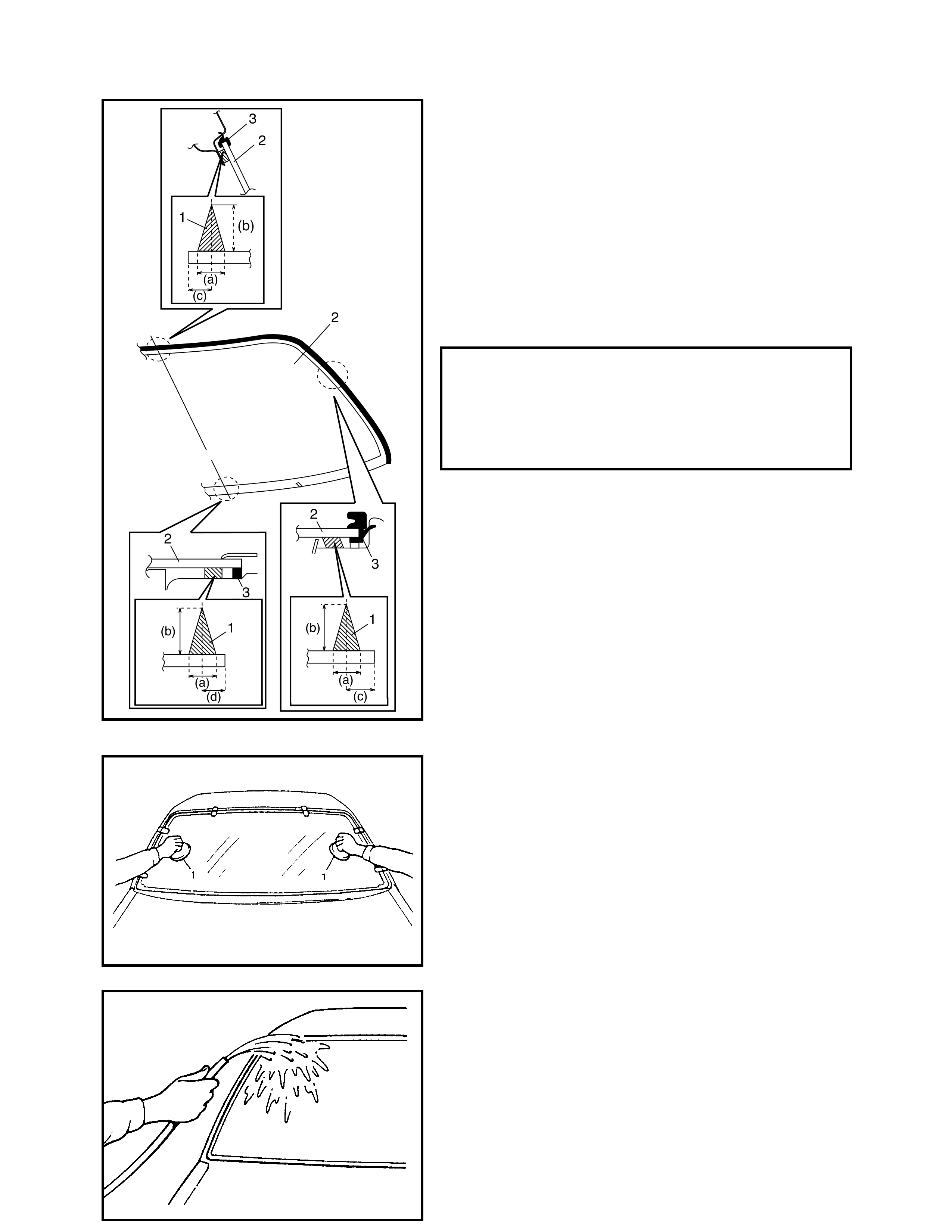
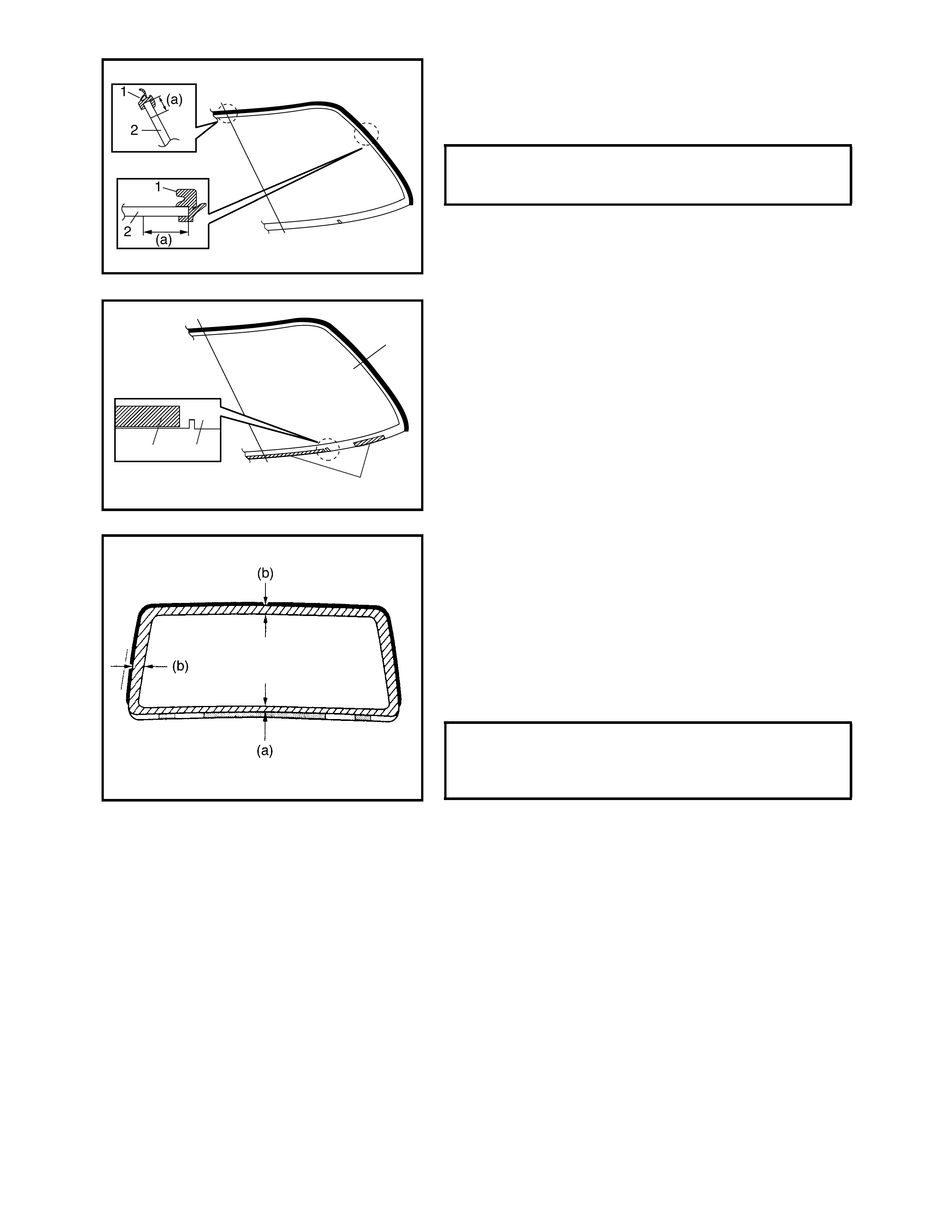
9. Apply primer to the moulding (3) along the moulding
surface.
10. Apply adhesive (1) referring to figure.
NOTE:
• Quickly press the glass (2) against the fitting surface of
the body panel after adhesive (1) is applied.
• Use of suction cups is helpful to hold and carry the
glass after the adhesive (1) is applied.
• Perfo rm Steps 8 to 9 withi n 10 m inutes t o en sure s uffi-
cient adhes ion .
• Be su re to ref er to the a dhe sive make r ’s i nstr uct ion for
proper handling and drying time.
• Start from the bottom side of the glass (2).
• Be careful not to damage the primer.
11. Holding the suction cups (1), place the glass onto the
body by aligning mating marks made in Step 3, then
press into position.
12. Check for water leakage by pouring water over wind-
shield with a hose. If leakage is found, dry windshield
and fill leak point with adhesive. If water still leaks,
remove the glass and repeat the installation procedure.
NOTE:
• Do not use high pressure water.
• Do not blow compressed air directly in areas where
adhesive is still drying.
• Do not use an infrared lamp or similar for drying.
ADHESIVE SPECIFICATIONS AND
POSITIONS FOR WINDSCREEN
(APPROX) WIDTH (a)
HEIGHT (b)
POSITION (c)
POSITION (d)
7 mm
15 mm
10 mm
17 mm
CAUTION:
Upon completion of installation, note the following.
• Sudden closing of the door(s) before adhesive is
completely set may cause the glass to become
loose or to come free. If the door(s) are opened or
closed before adhesive is completely set, ensure
that door windows are open and care is taken.
•If the moulding is not securely in place, hold it
down with tape until adhesive is completely set.
• Each adhesive has its own setting time.
• Be sure to refer to its manufacturer’s instruction,
check setting time of adhesive to be used and
observe precautions to be taken before adhesive is
set.
• Refrain from driving until adhesive is completely
set to ensure proper and sufficient adhesion.
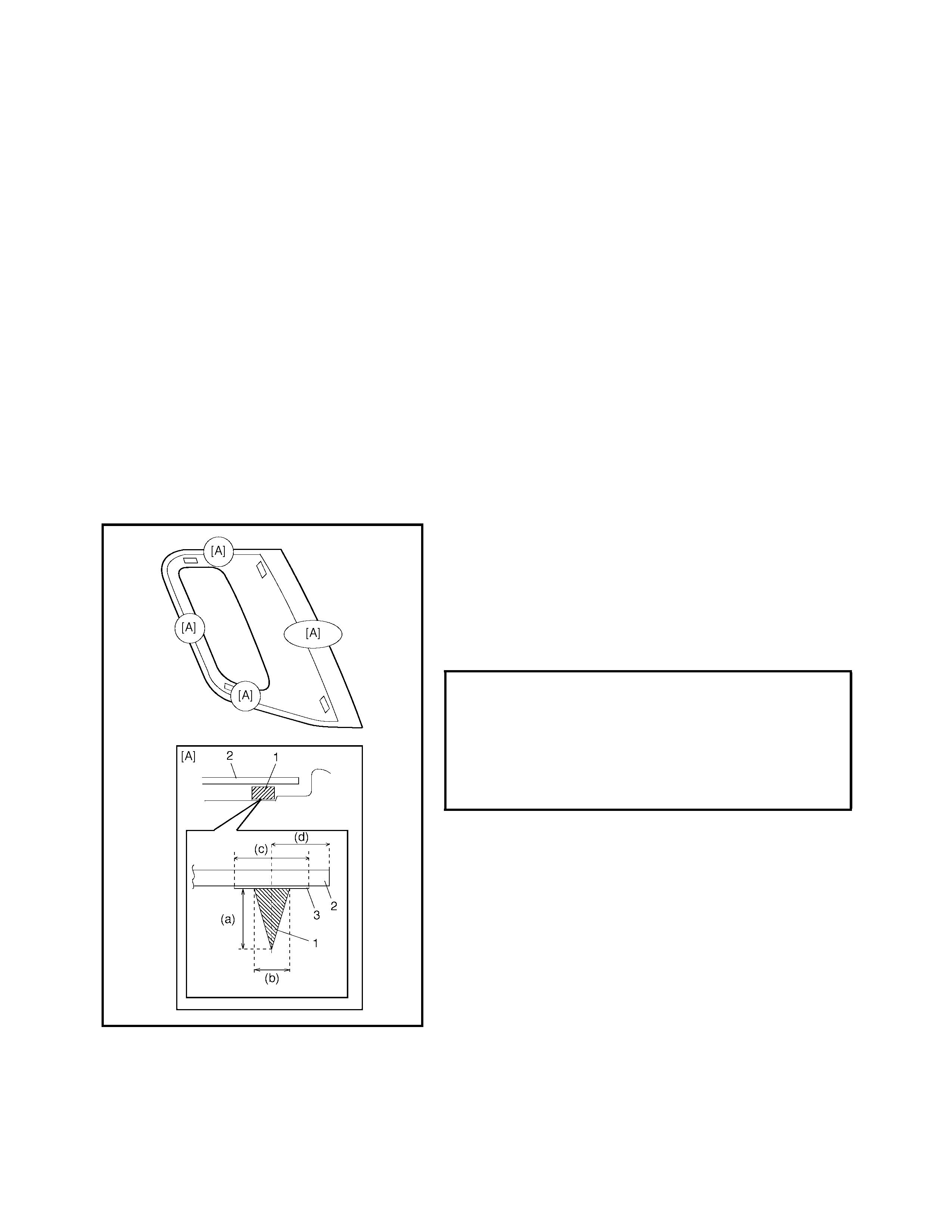
1.7 QUARTER WINDOW
REMOVAL AND INSTALLATION
Refer to 1.6 WINDSHIELD in this Section as removal and
installation procedures are basically the same. However,
note the following:
• Observe the following precautions when applying
adhesive (1) along the glass (2) edge.
• Adhesive (1) should be applied evenly, especially in
height.
• Be careful not to damage the primer (3).
• Press the glass against the body quickly after adhesive
(1) is applied.
.
ADHESIVE SPECIFICATION AND POSI-
TION FOR QUARTER WINDOW
HEIGHT (a)
WIDTH (b)
WIDTH (c)
GLASS FRONT & BOTTOM SECT. (d)
GLASS UPPER SECT. (d)
GLASS REAR SECT. (d)
13 mm
6 mm
14 mm
12 mm
11 mm
45 mm
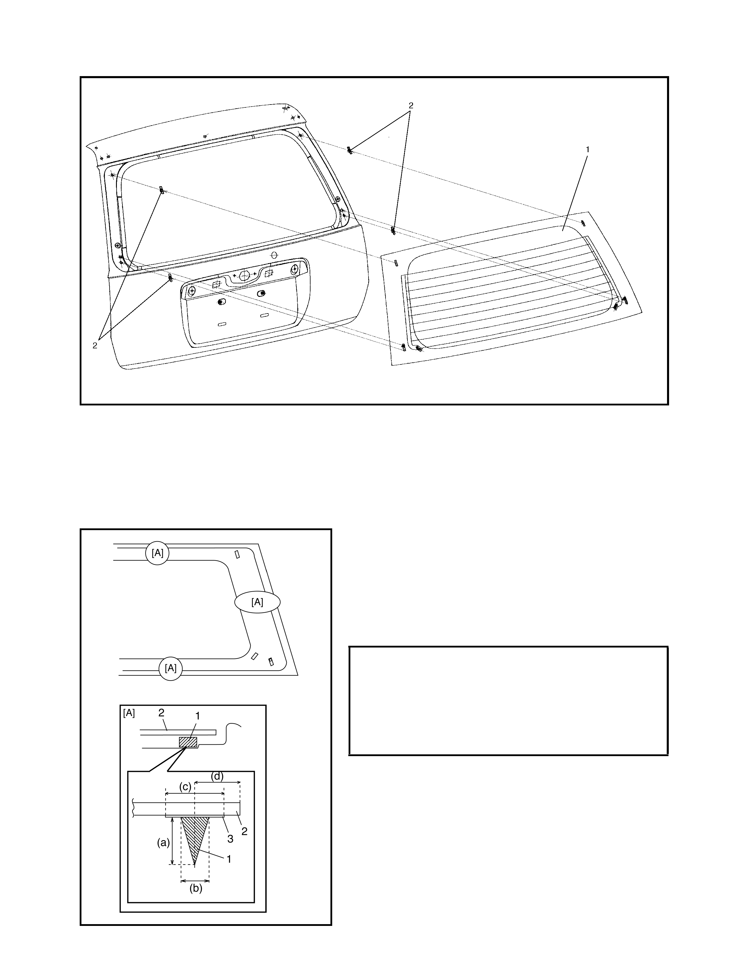
1.8 BACK DOOR GLASS
Legend
REMOVAL AND INSTALLATION
Refer to 1.6 WINDSHIELD in this Section as removal and
installation procedures are basically the same. However,
note the following:
• Observe the following precautions when applying
adhesive (1) along the glass (2) edge.
• Adhesive (1) should be applied evenly, especially in
height.
• Be careful not to damage the primer (3).
• Press the glass against the body quickly after adhesive
(1) is applied.
1. Back door glass 2. Fastener
ADHESIVE SPECIFICATION AND POSI-
TION FOR BACK DOOR GLASS
HEIGHT (a)
WIDTH (b)
WIDTH (c)
GLASS FRONT & BOTTOM SECT. (d)
GLASS UPPER SECT. (d)
GLASS REAR SECT. (d)
13 mm
6 mm
14 mm
14.5 mm
16 mm
45 mm
2. BODY STRUCTURE
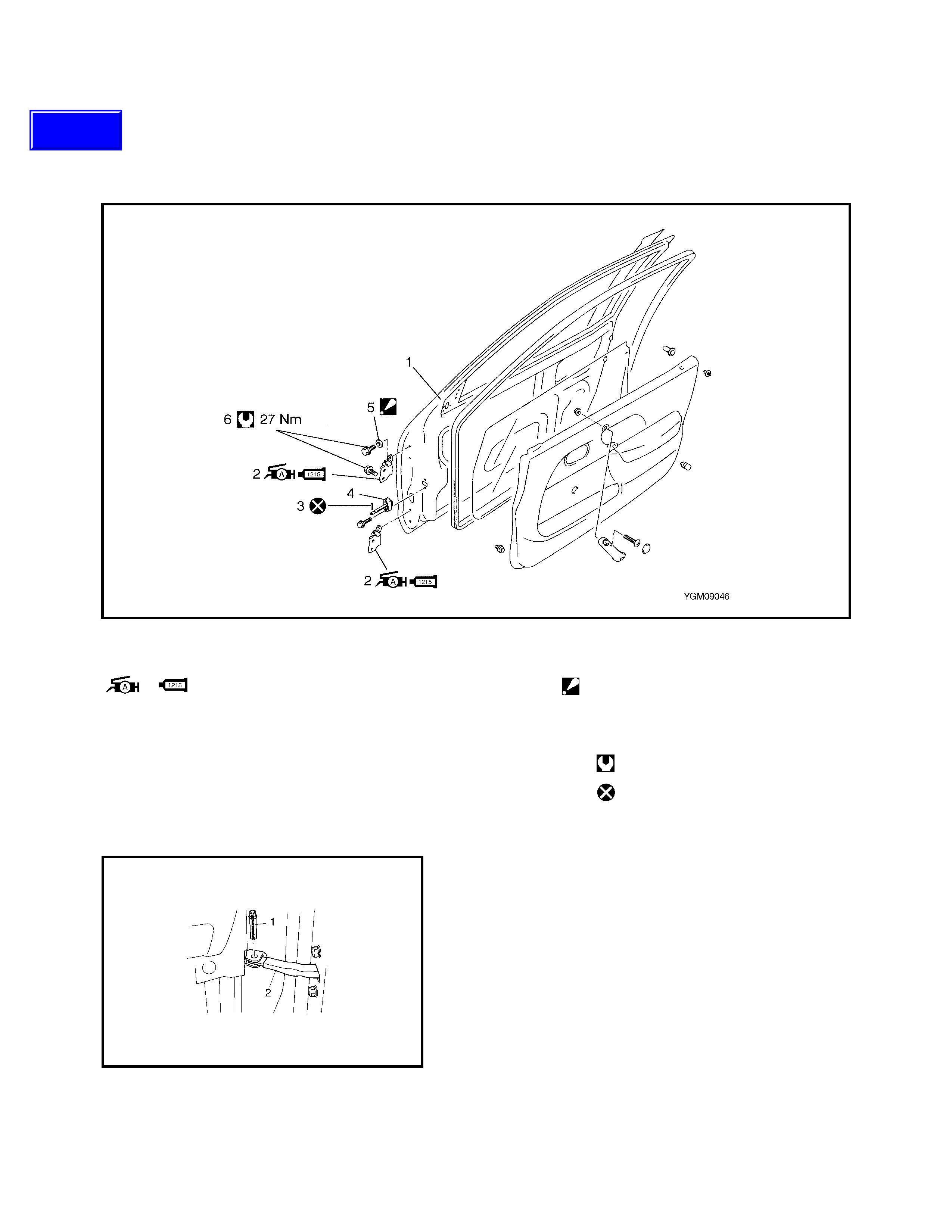
2.1 FRONT DOOR ASSEMBLY
Legend
REMOVAL
1. Remove the front fender, refer to 2.14, FRONT
FENDER in this Section.
2. Disconnect the door harness lead wires at each con-
nector, if equipped.
3. Remove stopper pin (1) from the door open stopper
(2).
1. Door panel 4. Door open stopper
2. Door hinge
: Apply Lithium grease to rotating part
: Apply sealant Three Bond No. 1215 to
contact face
5. Door hinge washer
: Not necessary to install
6. Front door hinge bolt
Tightening torque
3. Door stopper pin Do not reuse
Techline
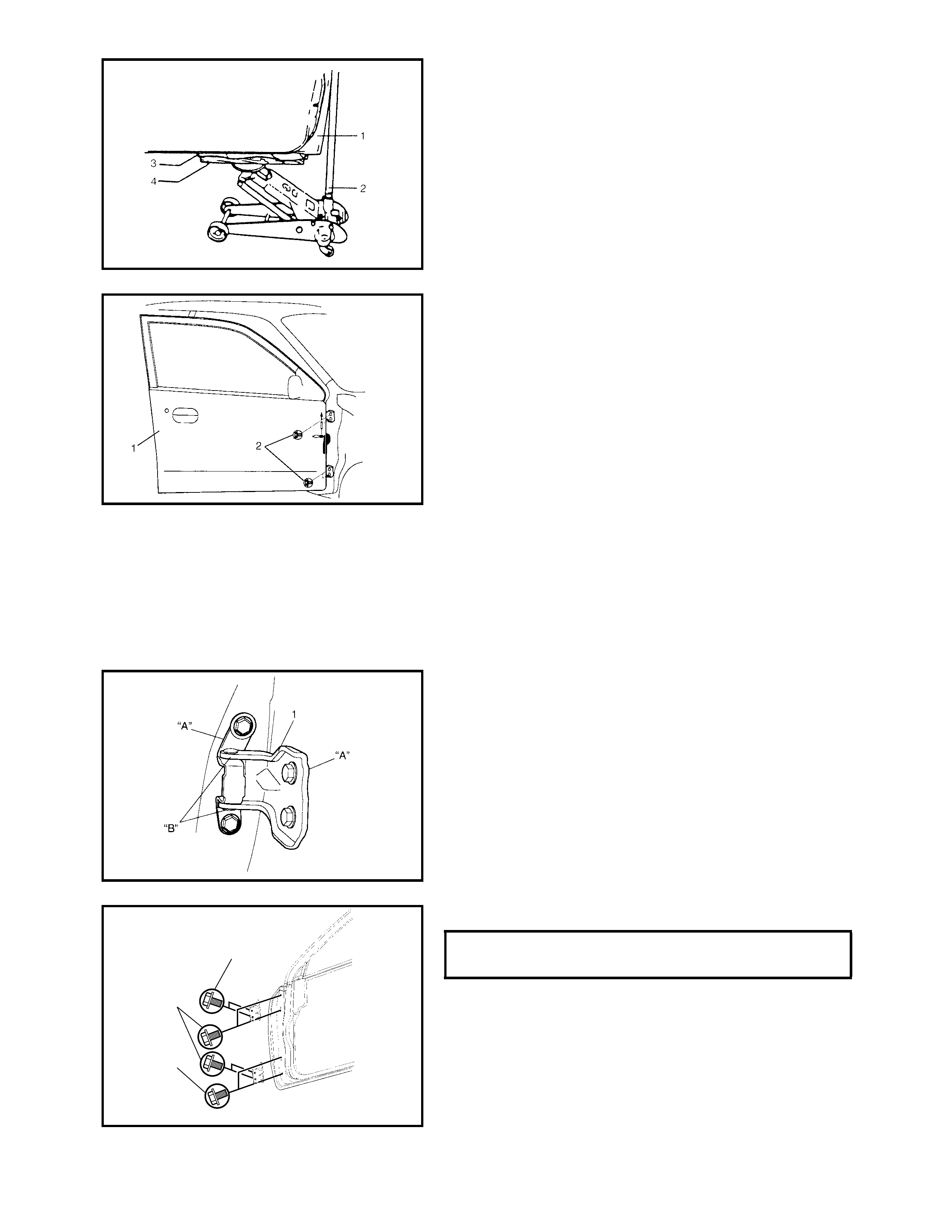
4. Support the door panel (1) using a jack (2) with a piece
of wood (4) covered with a cloth (3) placed between
jack (2) and panel (1) as shown.
5. Remove the door assembly (1) by removing hinge
mounting bolts (2).
INSTALLATION
Reverse removal procedure to install the door assembly
noting the following:
• When replacing the door, coat the inside of the
replacement door with anti-corrosion treatment wax.
Refer to 7.4 ANTI-CORROSION COMPOUND
APPLICATION AREA in this Section.
• Apply sealant to the contact face “A” of the hinge (1)
and apply grease to the rotating part “B” of the hinge
(1).
“A”: Sealant - Three Bond No. 1215
“B”: Lithium grease
• Tighten the hinge bolt (1) to specified torque.
DOOR HINGE MOUNTING BOLT (a)
TORQUE SPECIFICATION 27 Nm
1, (a)
1, (a)
1, (a)
• Ensure the door open stopper (1) is installed in the cor-
rect direction as shown.
• Adjust the door latch striker position, refer to
5.1 FRONT DOOR LOCK ASSEMBLY in this Section.
• Adjust the front door cushion so that the door closes
flush with the side body.
• After installation, open and close the door to check cor-
rect o pera t io n .
Replace the door open stopper pin if there is any
looseness.
• Replace the door weather-strip if it has become hard-
ened to prevent possible water leaks.
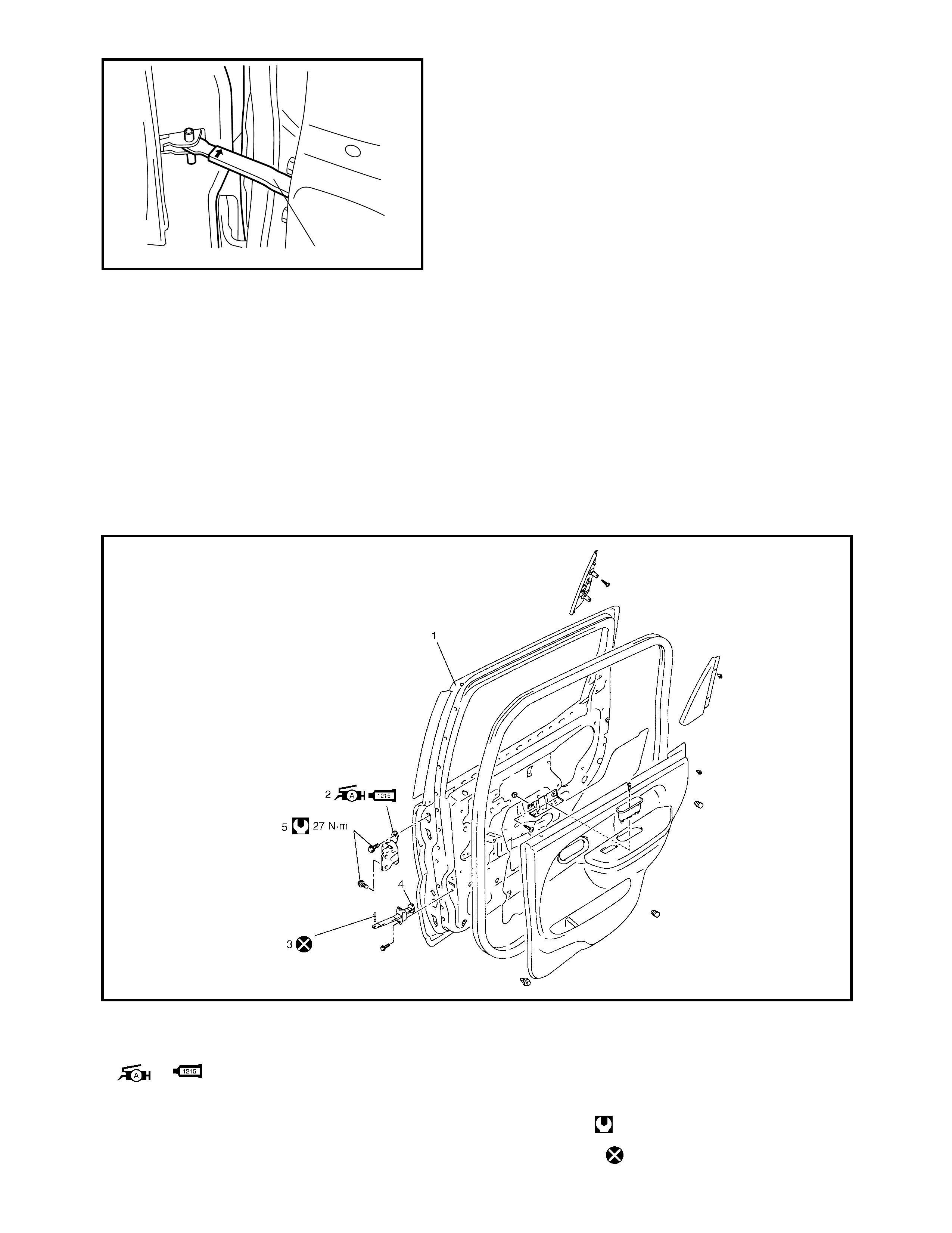
2.2 REAR DOOR ASSEMBLY
Legend
1
1. Door panel 3. Door stopper pin
2. Door hinge
: Apply Lithium grease to rotating part
: Apply sealant Three Bond No. 1215 to
contact face
4. Door stopper
5. Rear door hinge bolt
Tightening torque
Do not reuse.
REMOVAL AND INSTALLATION
Refer to 2.1 FRONT DOOR ASSEMBLY in this Section not-
ing the following instructions.
• Refer to the figure above for tightening torque, grease
and sealant locations.
• When the door open stopper is installed, be sure to
install in the correct orientation, see below.
Door stopper installation direction
Right side door: RR punch mark faces upward.
Left side door: RL punch mark faces upward.
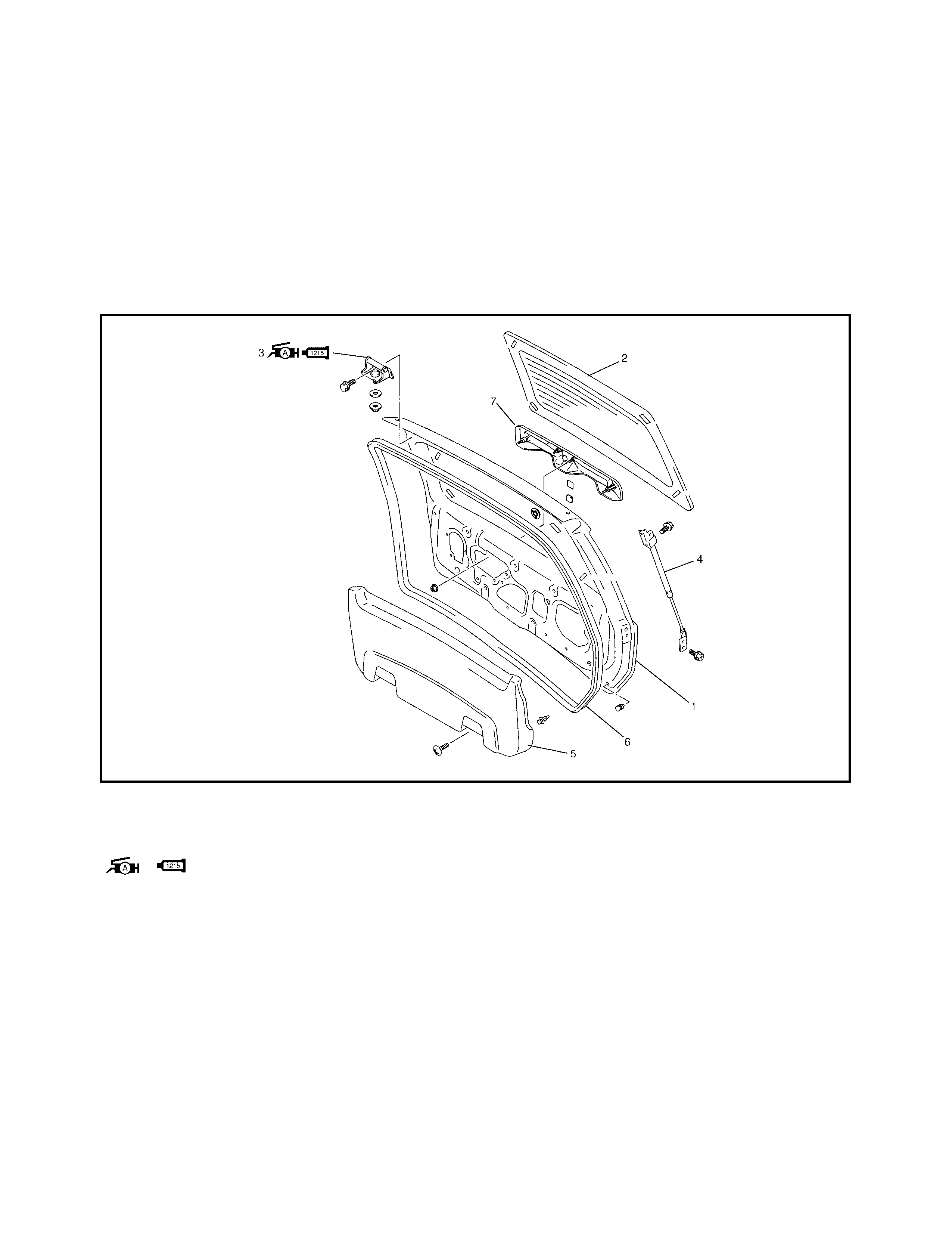
2.3 BACK DOOR ASSEMBLY
Legend 1. Back door panel assembly 4. Back door support strut
2. Back door window glass 5. Back door trim
3. Back door hinge
: Apply Lithium grease to door hinge
: Apply sealant Three Bond No. 1215 to contact
face
6. Weather strip
7. Licence garnish
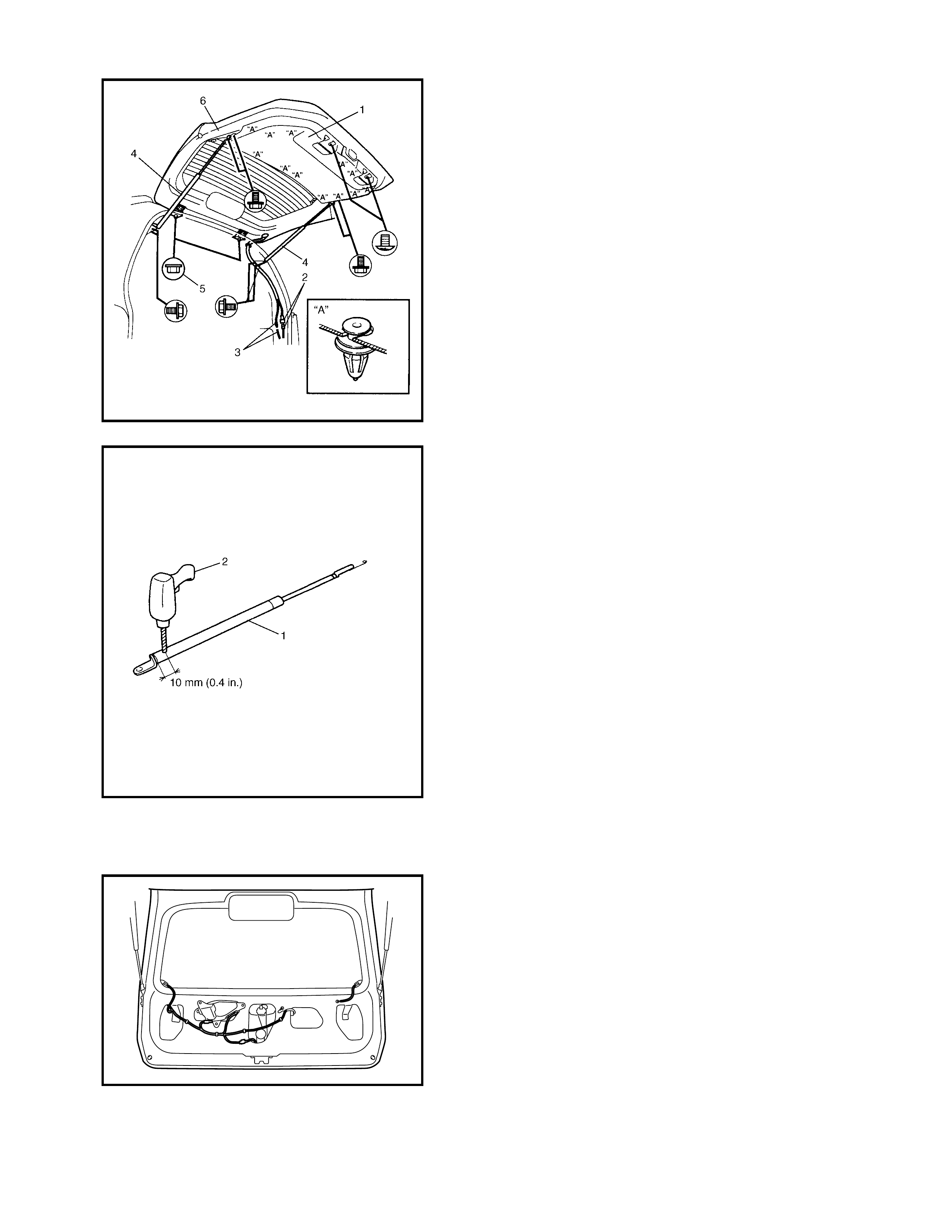
REMOVAL
1. Remove the back door trim (1).
2. Remove the related section of headlining and quarter
trim, refer to 6.2 HEADLINING in this Section.
3. Disconnect the back door harness connectors (2) and
washer hose (3).
4. Remove the wire harness connectors inside the back
door.
5. Remove the back door support strut (4) (unbolt door
side first then unbolt body side).
6. Remove the door hinge nuts (5) and remove the back
door assembly (6).
WARNING:
Handling of Back Door Support Strut
• Do not disassemble the support strut (1) as its cyl-
inder is filled with gas.
• Handle the support strut carefully. Do not scar or
scratch exposed surface of its piston rod, and
never allow any paint or oil to adhere to its surface.
• Do not turn piston rod with support strut fully
extended.
• When discarding the removed back door support
strut, use a 2–3 mm drill bit (2) to make a hole as
shown.
• When drilling (2) wear safety goggles. Although the
gas is harmless it may escape rapidly along with
metal filings creating a safety risk.
INSTALLATION
Reverse removal procedure to install back door noting the
following:
• Secure the wiring harness.
• Adjust the door latch striker position, refer to 5.3 BACK
DOOR LOCK ASSEMBLY in this Section.
• Adjust the door cushion so that the door contacts the
body when closed.
• Adjust the door clearance by loosening the door hinge
mounting bolts and nuts, refer to 2.17 PANEL
CLEARANCE in this Section.
• Apply sealant to the contact face “A” of door hinge (1)
and apply grease to the rotating part “B” of the hinge
(1).
“A”: Sealant - Three Bond 1216
“B”: Lithium grease
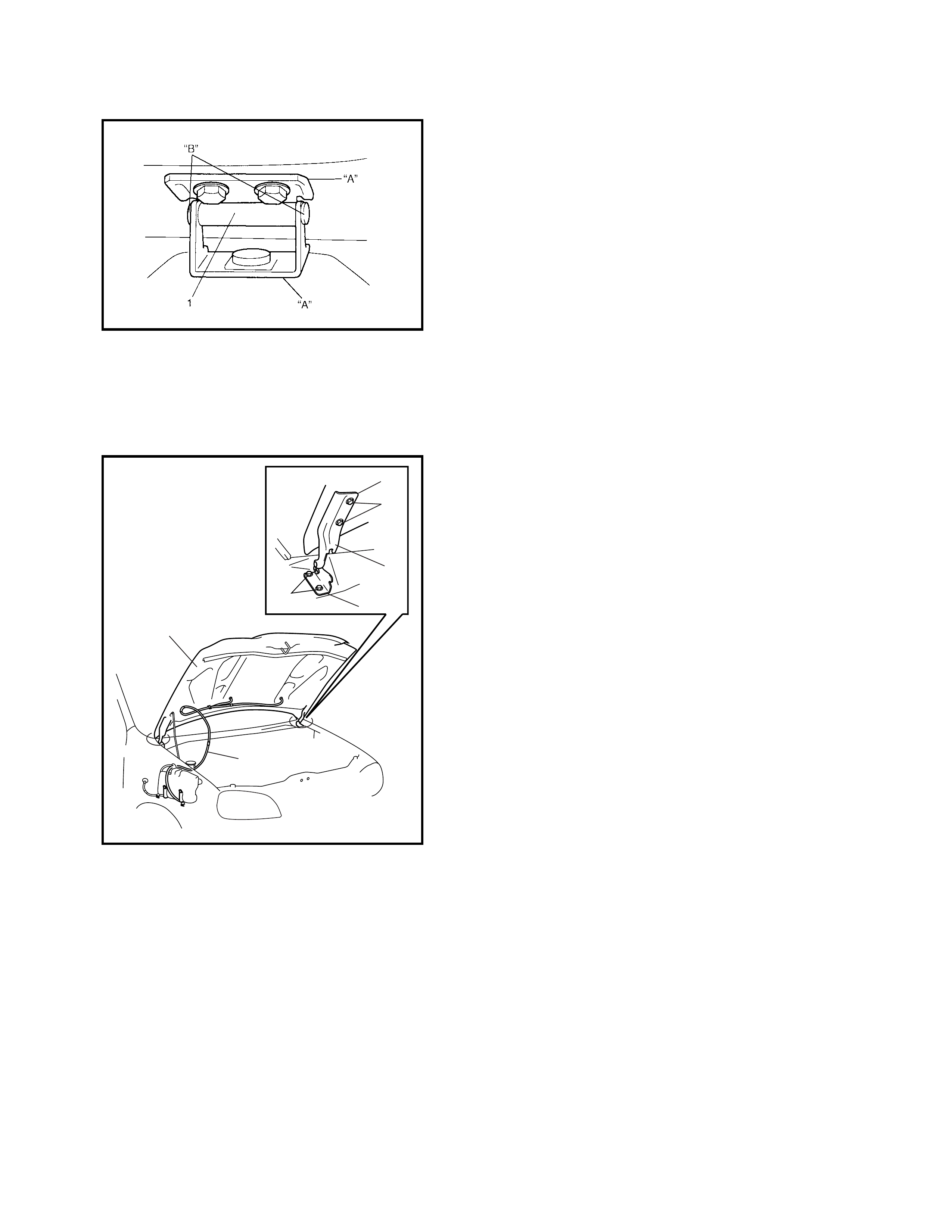
2.4 HOOD
REMOVAL
CAUTION: Place a fender cover on the fender “A” as
shown to prevent damage.
1. Remove the window washer hose (1) from the
hood (2).
2. Remove the four mounting bolts (3) to detach the
hood (2).
INSTALLATION
Reverse removal procedure to install the hood noting the
following:
• Apply sealant to the contact face “B” of the hood
hinge (4).
“B”: Sealant - Three Bond 1216
ADJUSTMENT
To adjust the hood alignment refer to the following:
• Hood position adjustment.
Fore-and-aft and right-and-left adjustment.
Adjust the hood clearance by loosening the hood
mounting bolts, making adjustments then re-tighte ning
the mounting bolts, refer to 2.17 PANEL CLEARANCE
in this Sectio n.
3
3
4
“B”
“B”
1
2
“A”
“A”
• Vertical adjustment
If only one side (right or left) of the hood is not level
with the front fender, adjust by tightening or loosening
the hood cushion (1).
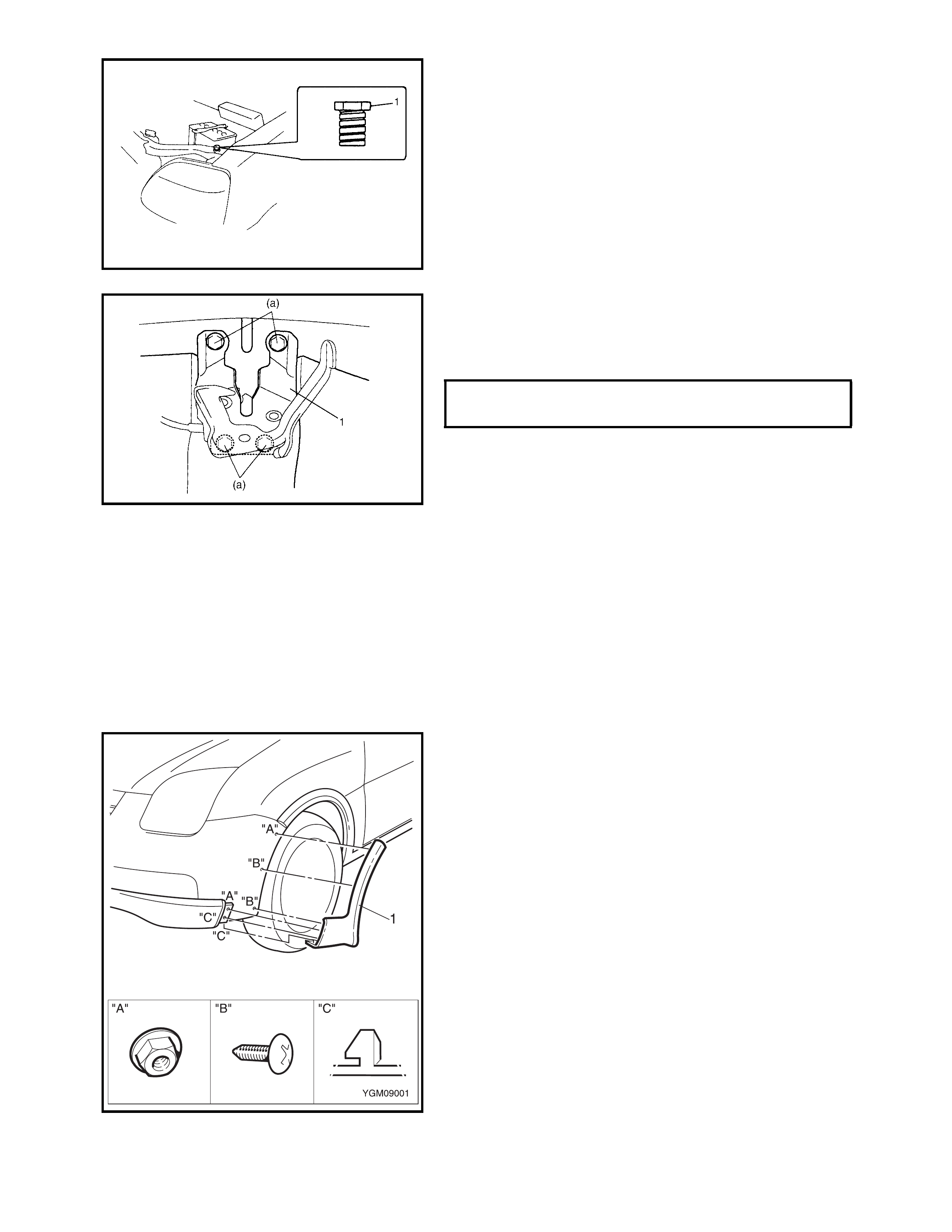
• Hood lock position adjustment
When installing the hood lock (1), set the lock to the
highest position then move it in a vertical direction for
correct adjustment with the hood striker.
INSPECTION
Check that the hood opens and closes smoothly and cor-
rectly. Lubricate if necessary. Also check that the second-
ary latch operates correctly (check that the secondary latch
keeps the hood from opening all the way) and the hood
locks securely when closed.
Adjust the hood lock position if necessary.
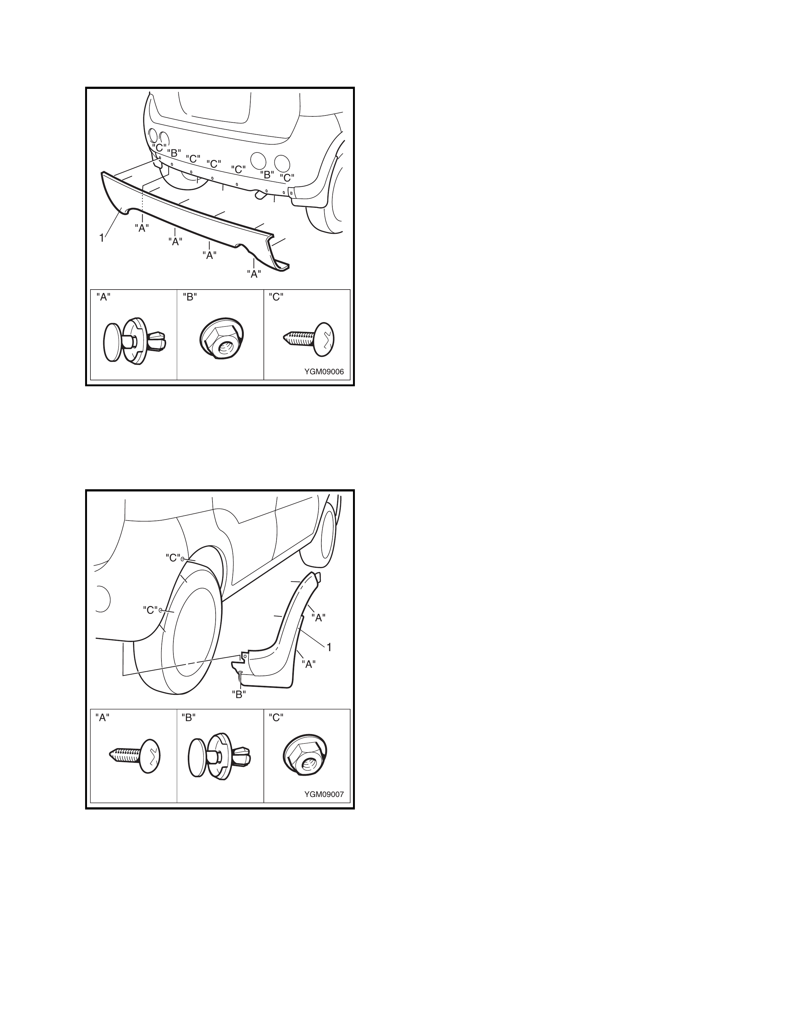
2.5 FRONT BUMPER SIDE EXTENSION
REMOVAL
1. Partially remove the front fender liner, refer
2.14 FRONT FENDER.
2. Remove the nuts “A” two places.
3. Remove the screws “B” two places.
4. Remove the front bumper side extension (1), detaching
the clips “C” two places.
INSTALLATION
Reverse removal procedure for installation.
HOOD LATCH BOLTS (a)
TORQUE SPECIFICATIONS 10 Nm
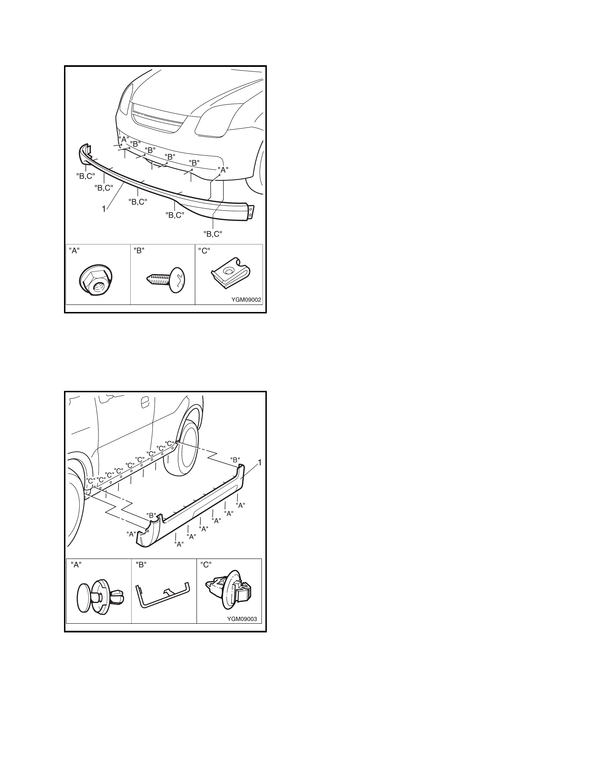
2.6 FRONT BUMPER CENTRE EXTENSION
REMOVAL
1. Remove the front bumper, refer 2.12, FRONT
BUMPER.
2. If required, d etach th e front s ecti on of the fr on t bum per
side extension from the centre extension (1).
3. Remove the nuts “A” two places.
4. Remove the screws “B” four places.
5. Remove the screws “B” and nuts “C” five places.
6. Remove the front bumper centre extension.
INSTALLATION
Reverse removal procedure for installation.
2.7 SILL PANEL EXTENSION
REMOVAL
1. Remove the clip “A” seven places.
2. Protect the paintwork with a shop rag and using a
screwdriver, carefully prise the sill panel extension (1)
from the front and rear fender extensions two places
“B”.
3. Protect the paintwork with a shop rag and using a
screwdriver , carefully prise the sill panel extension from
the vehicle nine places “C” and remove the extension.
INSTALLATION
Reverse removal procedure for installation.
2.8 FRONT FENDER EXTENSION
REMOVAL
1. If required, detach the front section of the sill panel
extension from the front fender extension (1).
2. Remove the clip “A” three places.
3. Protect the paintwork with a shop rag and using a
screwdriver, carefully prise the fender extension from
the front fender five places “B”.
INSTALLATION
Reverse removal procedure for installation.
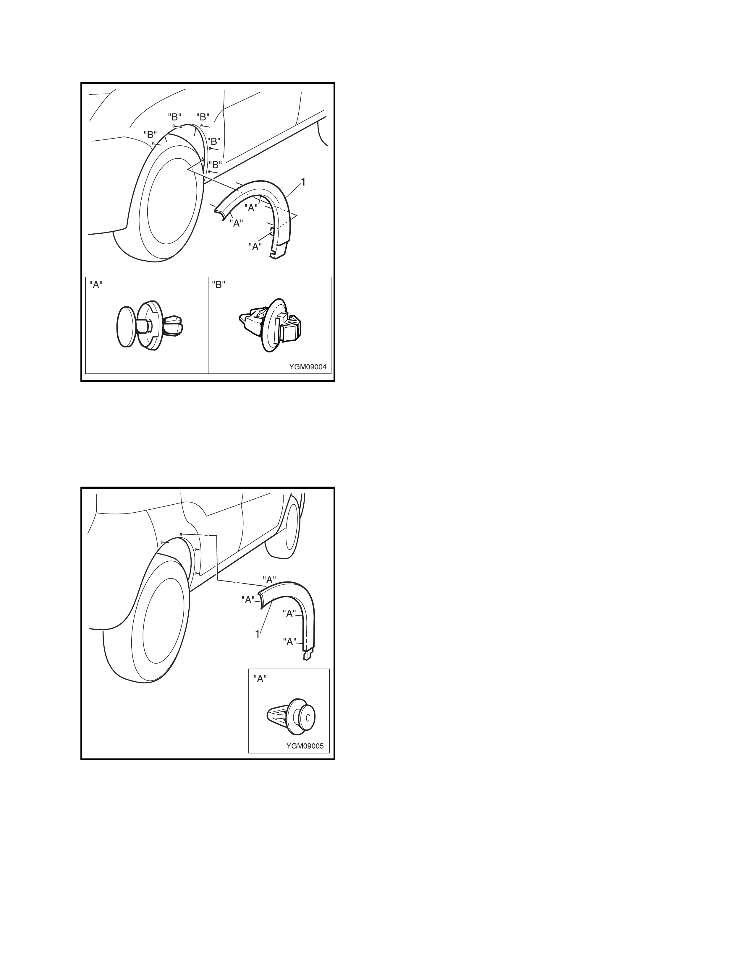
2.9 REAR FENDER EXTENSION
REMOVAL
1. If required, detach the rear section of the sill panel
extension from the rear fender extension (1).
2. Protect the paintwork with a shop rag and using a
screwdriver, carefully prise the fender extension from
the rear fender five places “A”.
INSTALLATION
Reverse removal procedure for installation.
2.10 REAR BUMPER CENTRE EXTENSION
REMOVAL
1. Remove the rear bumper, refer 2.13 REAR BUMPER.
2. Remove the clips “A” four places.
3. Remove the nuts “B” two places
4. Remove the screws “C” five places.
5. Remove the rear bumper centre extension (1).
INSTALLATION
Reverse removal procedure for installation.
2.11 REAR BUMPER SIDE EXTE NS ION
REMOVAL
1. Remove the screws “A” two places
2. Partially remove the rear fender liner.
3. If required, detach the end of the rear bumper centre
extension from the rear bumper side extension (1).
4. Remove the clip “B” one place.
5. Remove the nuts “C” two places.
6. Remove the side extension.
INSTALLATION
Reverse removal procedure for installation.
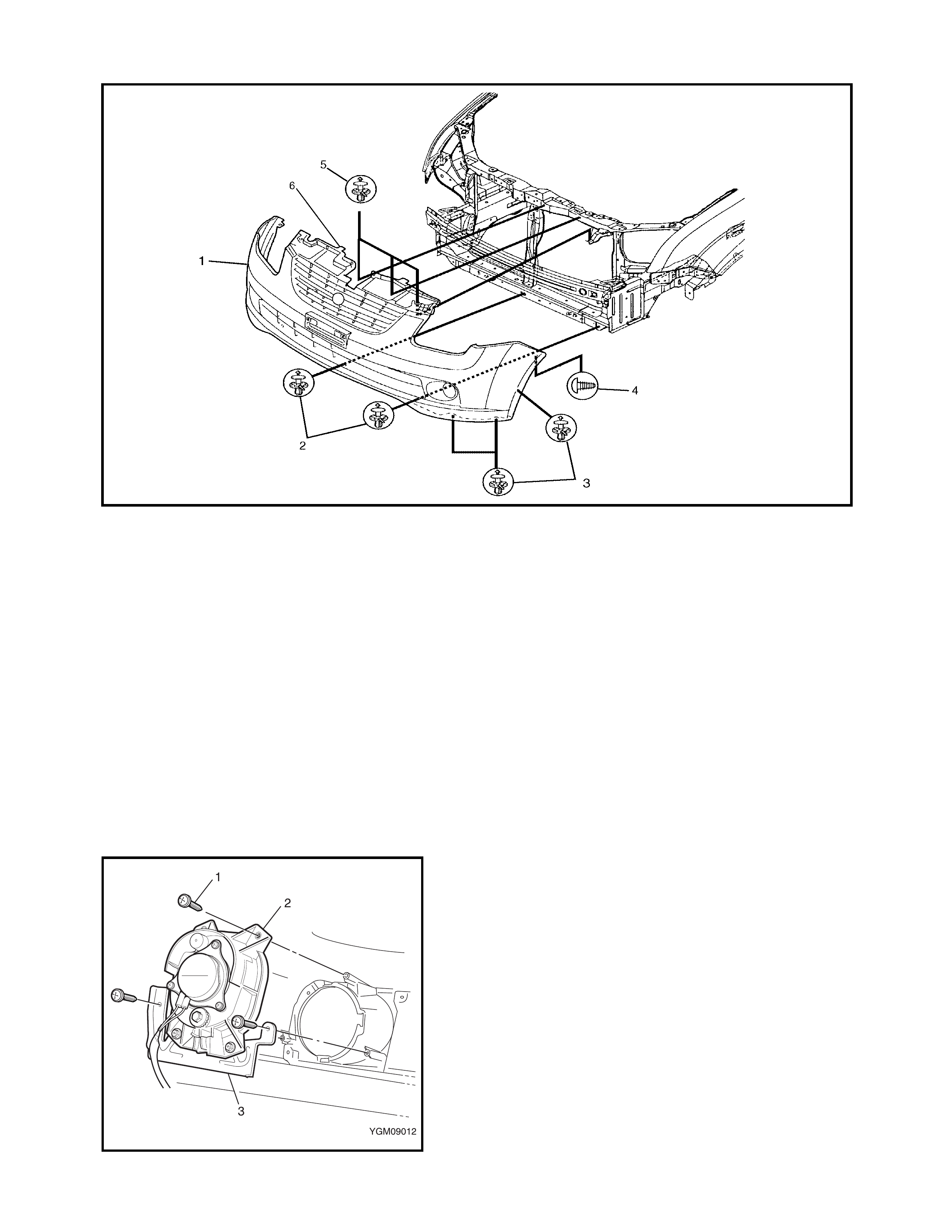
2.12 FRONT BUMPER
Legend
REMOVAL
1. Disconnect the fog lamp connectors.
2. Remove the clips (2) attaching the bumper to the
vehicle, three places.
3. Remove the clips (3) attaching the bumper (and front
bumper side extension) to the fender liner each side.
4. Remove the screw (4) attaching the bumper to the
fender each side.
5. Remove the clips (5) attaching the bumper to the
vehicle.
6. Prise the two retainers securing the bumper to the
radiator support panel and remove the bumper.
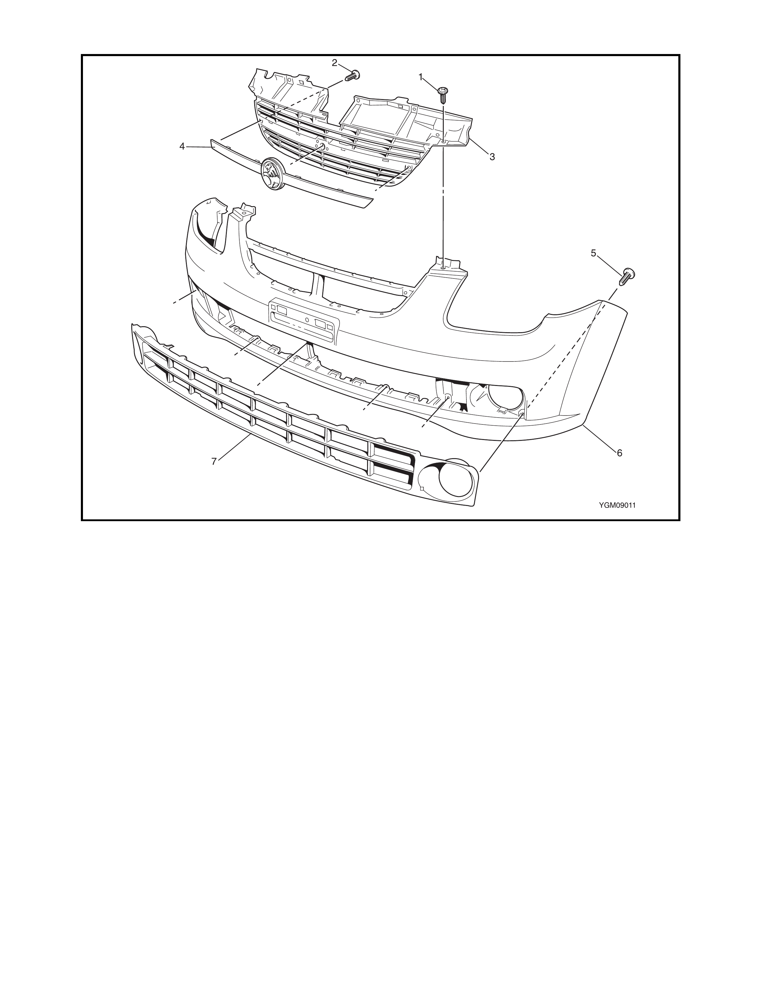
DISASSEMBLE
1. Remove the front bumper side and centre extensions,
refer 2.5 FRONT BUMPER SIDE EXTENSION and
2.6 FRONT BUMPER CENTRE EXTENSION in
this Section.
2. Remove the screws (1) three places attaching the fog
lamp and bracket to the bumper.
3. Remove the fog lamp and repeat for the other side.
4. Remove the screws and unclip the radiator grille,
garnish and lower grille as required, refer following
illustration.
NOTE: Use care the retaining clips can be easily broken.
1. Front bumper 3. Clips 5. Clips
2. Clips 4. Screw 6. Retainer
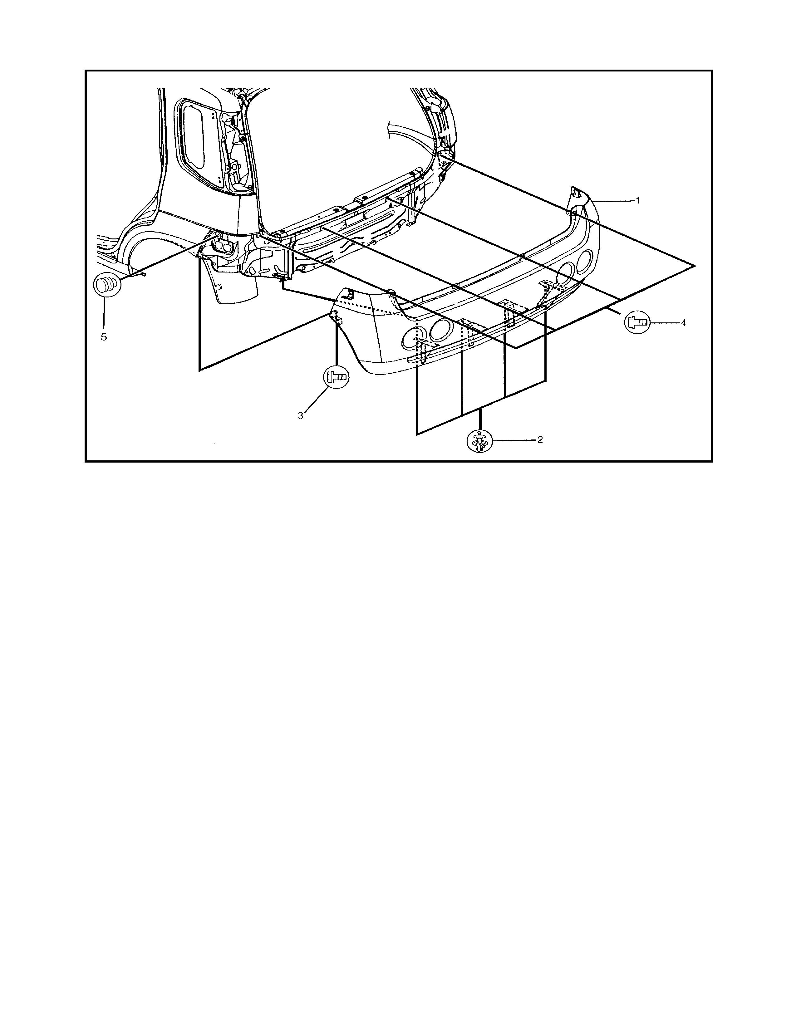
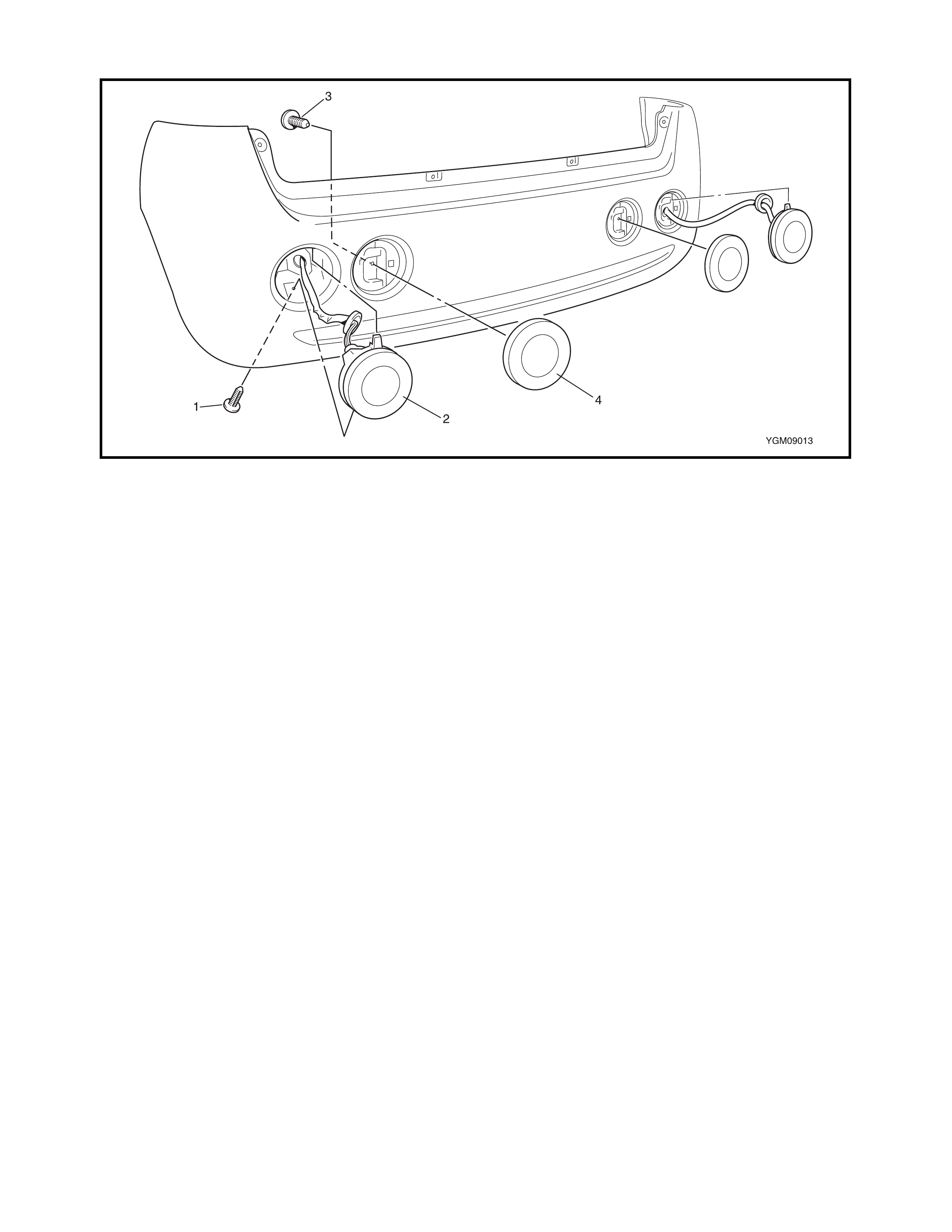
2.13 REAR BUMPER
Legend
REMOVAL
1. Partially remove the rear bumper side extension, refer
2.11 REAR BUMPER SIDE EXTENSION, and the rear
fender liner where it attaches the rear bumper.
2. Remove the clips (2) attaching the bumper to the
vehicle, four places.
3. Remove the bolt (3) attaching the bumper to the
vehicle each side.
4. Remove the bolt (4) attaching the bumper to the
vehicle four places.
5. Remove the bumper from the vehicle, disengaging it
from the damper (5) each side.
6. Disconnect the brake lamp wiring connector.
1. Rear bumper 3. Bolt 5. Damper
2. Clip 4. Bolt
DISASSEMBLE
Legend
1. Remove the rear bumper side and centre extensions,
refer 2.10, REAR BUMPER CENTRE EXTENSION
and 2.11, FRONT BUMPER SIDE EXTENSION in this
Section.
2. Remove the screw attaching the brake & tail light and
remove the light unattaching the upper lug from the
bumper.
3. Remove the screw attaching the reflector and unclip
the reflector from the rear of the bumper.
4. Repeat for the opposite side.
INSTALLATION
Reverse removal procedure to install the front bumper.
Adjust panel clearance, refer to 2.17 PANEL CLEARANCE
in this Section.
1. Screw 3. Screw
2. Brake & tail light 4. Reflector
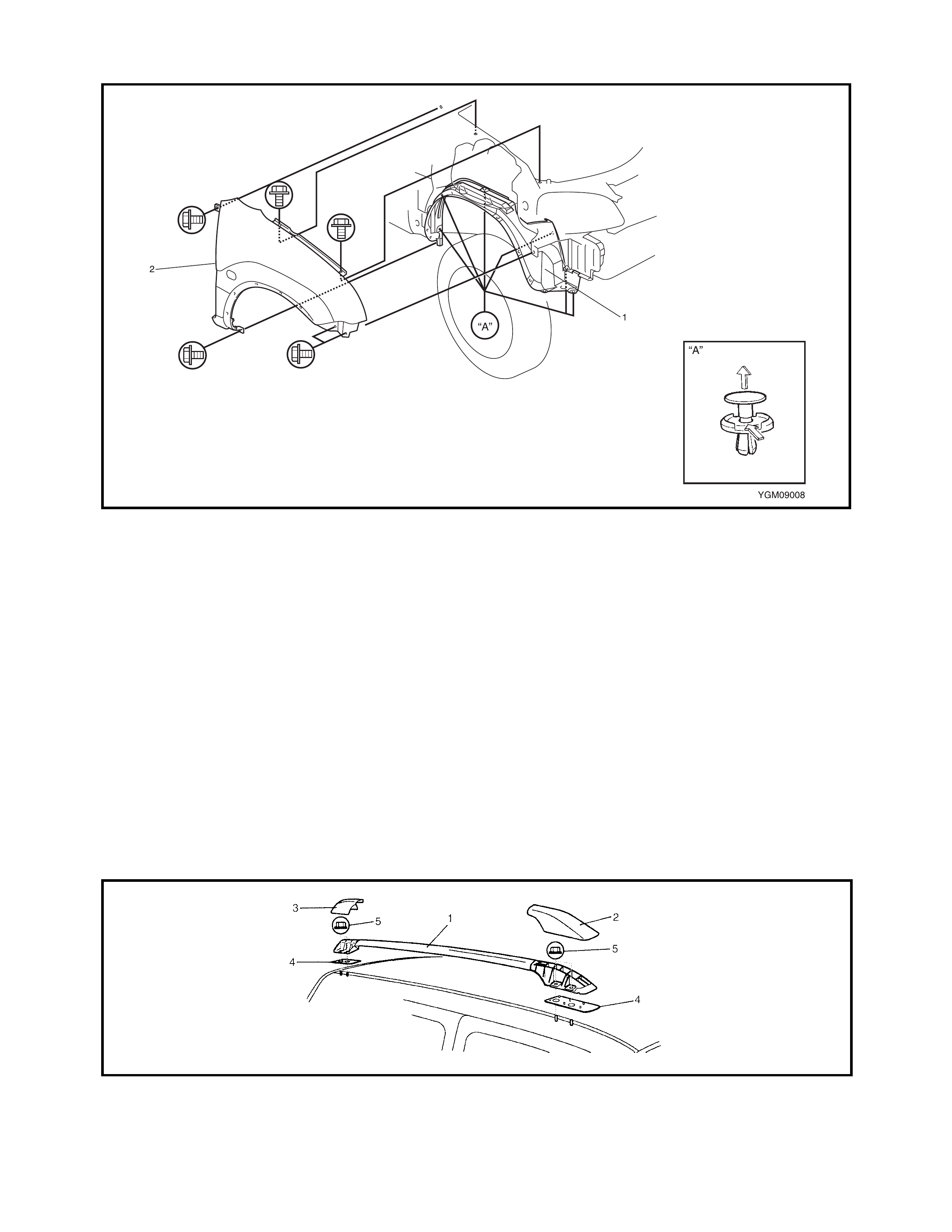
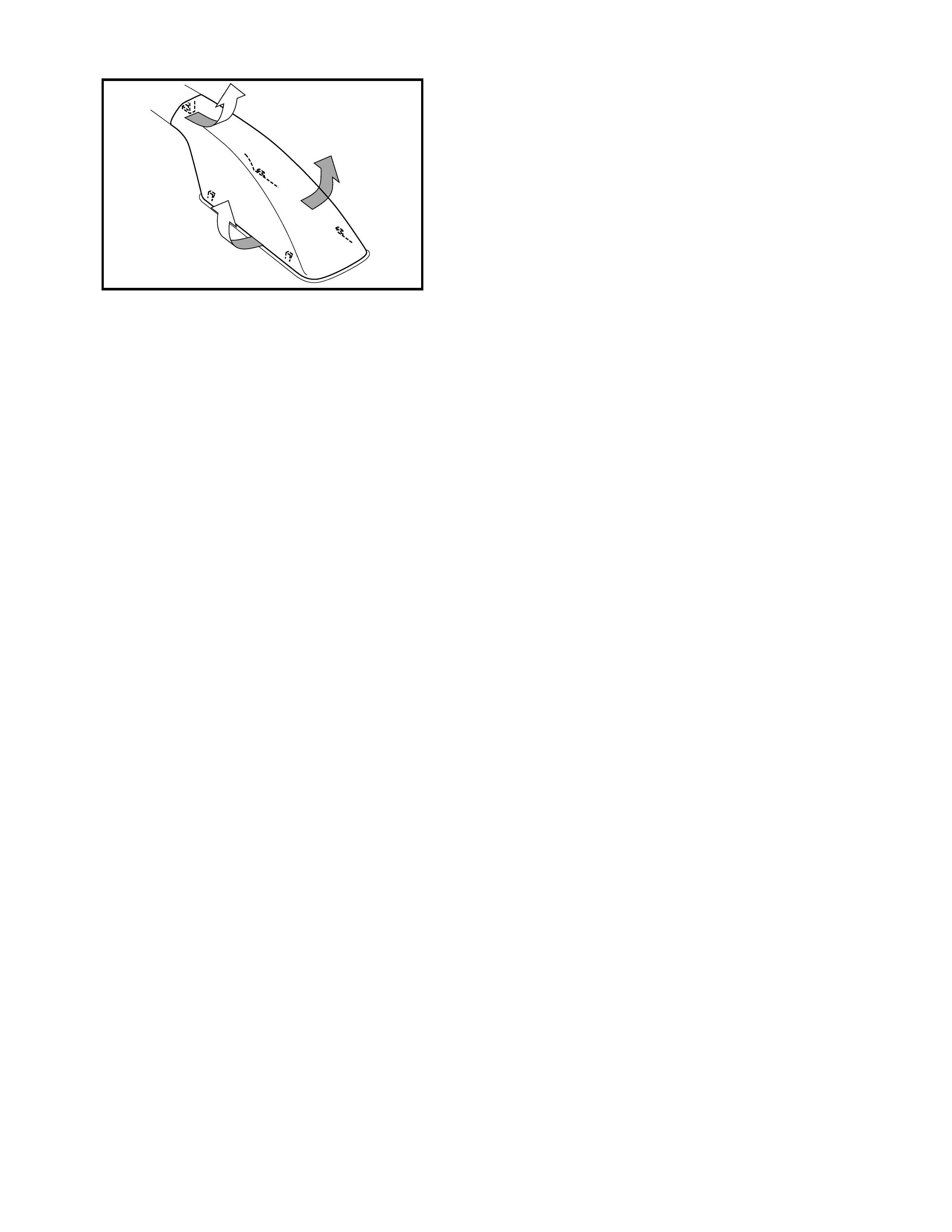
2.14 FRONT FENDER
Legend
REMOVAL
1. Remove the front bumper, refer to 2.12 FRONT
BUMPER in this Section.
2. Disconnect the side turn signal lamp connector.
3. Remove the front fender lining (1).
4. Remove the front fender (2).
INSTALLATION
Reverse removal procedure to install the front fender not-
ing the following:
• Repair any paint damage on the fender bolts.
• Adjust the panel clearance, refer to 2.17 PANEL
CLEARANCE in this Section.
2.15 ROOF RAILS
Legend
1. Front fender lining 2. Front fender 3. Front fender side moulding
1. Roof rail assembly 4. Base seal
2. Front cap 5. Nut
3. Rear cap
REMOVAL
1. Remove the roof rail front and rear caps as shown.
2. Remove the nuts.
3. Remove the roof rail assembly.
INSTALLATION
Reverse removal procedure for installation.
Confirm that each roof rail fixing nut is tightened securely.
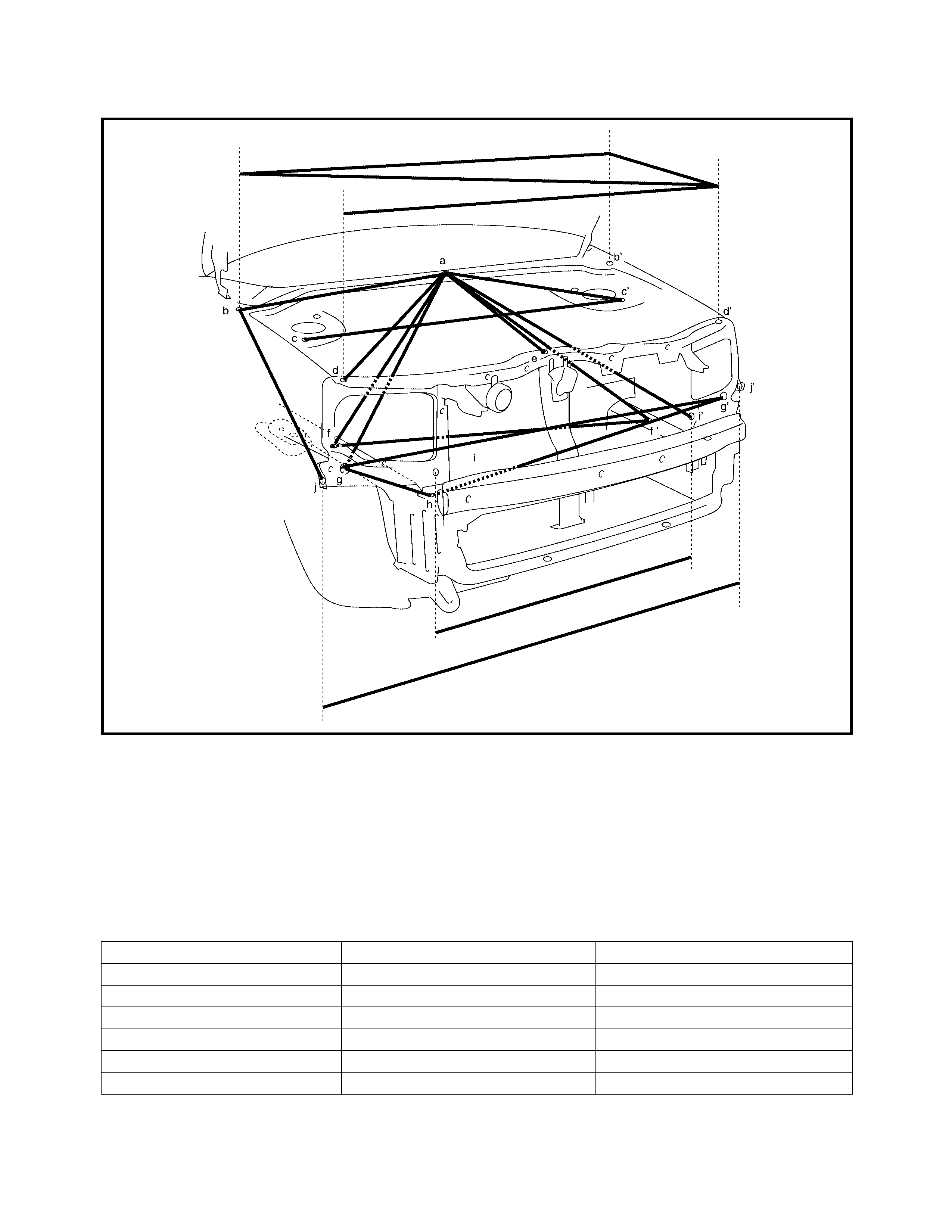
2.16 BODY DIMENSIONS
ENGINE ROOM
Legend
Hole to hole distance
a. Garnish installation
centre hole (φ5) d (d’). Front fender
installation hole g (g’). Jig hole (φ15 mm)
h. Bumper member upper side
installation hole
b (b’). Front fender
installation hole e. Hood cushion installation hole
f (f’). Engine mounting installation
front hole i (i’). Head light installation hole
c (c’). Strut installation front
hole j (j’). Front fender installation hole
a-b: 673 mm a-i’: 798 mm f-f’: 954 mm
a-c’: 584 mm b-b’: 1340 mm g-g’: 1315 mm
a-d: 760 mm b-d’: 1393 mm g-h: 231 mm
a-e: 599 mm b-j: 606 mm g’-h: 1139 mm
a-f: 774 mm b’-d’: 401 mm i-i’: 922 mm
a-f’: 836 mm c-c’: 1098 mm j-j’: 1417 mm
a-g: 889 mm d-d’: 1328 mm
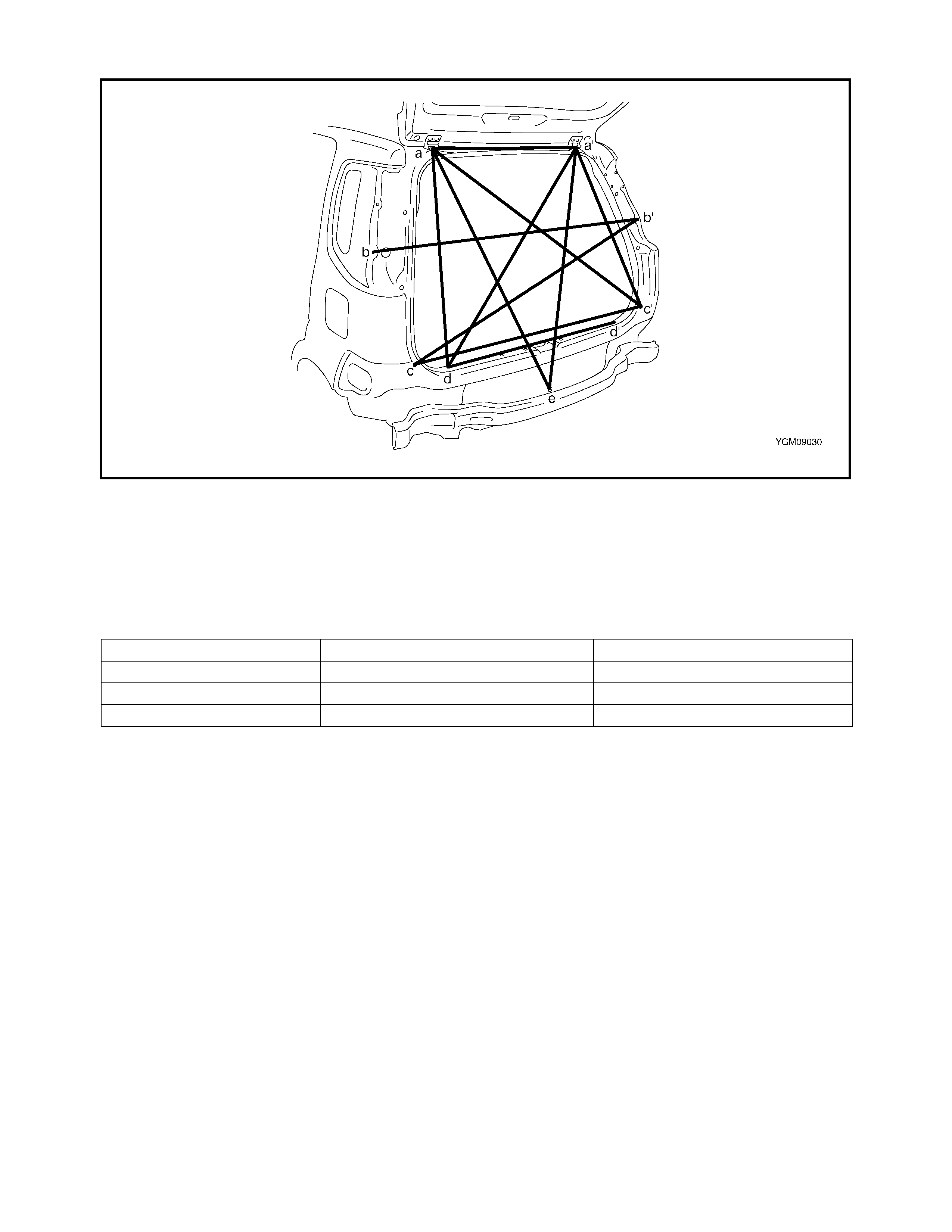
BACK DOOR
Legend
Hole to hole distance
a (a’). Back door hinge installation
hole c (c’). Rear bumper installation
hole e. Centre jig hole (φ7 mm)
b (b’). Rear combination lamp
installation hole d (d’). Tail end member trim
installation hole
a-a’: 725 mm a’-c’: 794 mm b’-c: 1340mm
a-c’: 1229 mm a’-d: 1128 mm c-c’: 1215 mm
a-d: 799 mm a’-e: 1096 mm d-d’: 875 mm
a-e: 1096 mm b-b’: 1340 mm
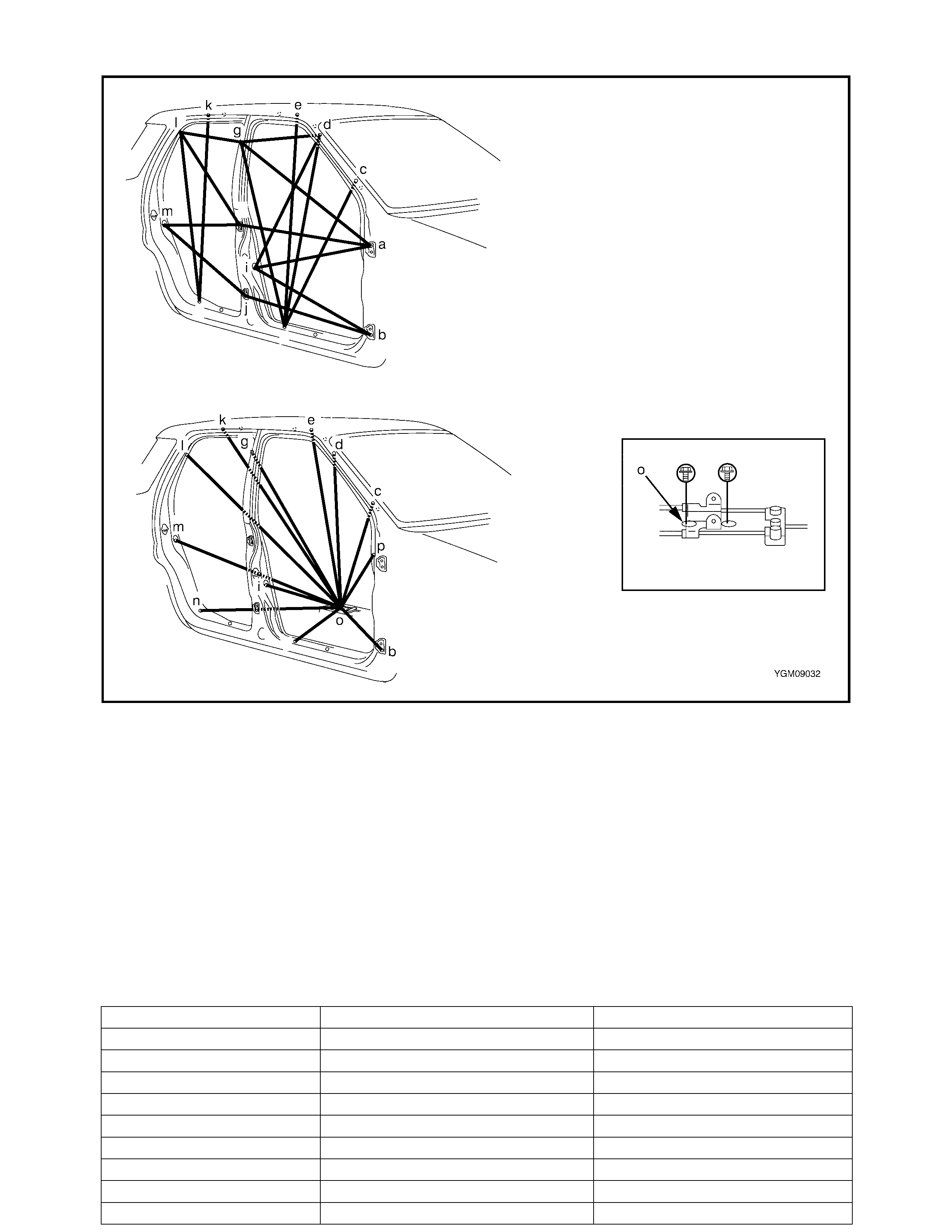
SIDE BODY
Legend
Hole to hole distance
a. Front door upper hinge
installation hol e g. Front shoulder adjuster instal-
lation upper hole l. Rear door rear notch
b. Front door lower hinge
installation hol e h. Rear door upper hinge instal-
lation hole m. Rear door switch installation
hole
c. Front pillar inner trim instal-
lation lower hole i. Front door switch installation
hole n. Side sill scuff installation rear
hole
d. Front pillar inner trim instal-
lation upper hole j. Rear door lower hinge instal-
lation hole o. Parking brake cable bracket
installation rear hole
e. Assistant grip installation
front hole k. Assistant grip installation
hole p. Steering support member
installation upper hole
f. Side sill scuff installation
rear hole
a-g: 1166 mm d-i: 820 mm i-o: 742 mm
a-h: 942 mm d-o: 1252 mm j-m: 895 mm
a-i: 901 mm e- f: 1077 mm k-n: 1089 mm
b-i: 891 mm e-o: 1244 mm k-o: 1321 mm
b-j: 902 mm f-g: 1048 mm l-n: 948 mm
b-o: 1222 mm f-o: 785 mm l-o: 1323 mm
c-f: 884 mm g-l: 621 mm m-o: 1111 mm
c-o: 1282 mm g-o: 1147 mm n-o: 813 mm
d-f: 993 mm h-l: 846 mm o-p: 1229 mm
d-g: 580 mm h-m: 813 mm
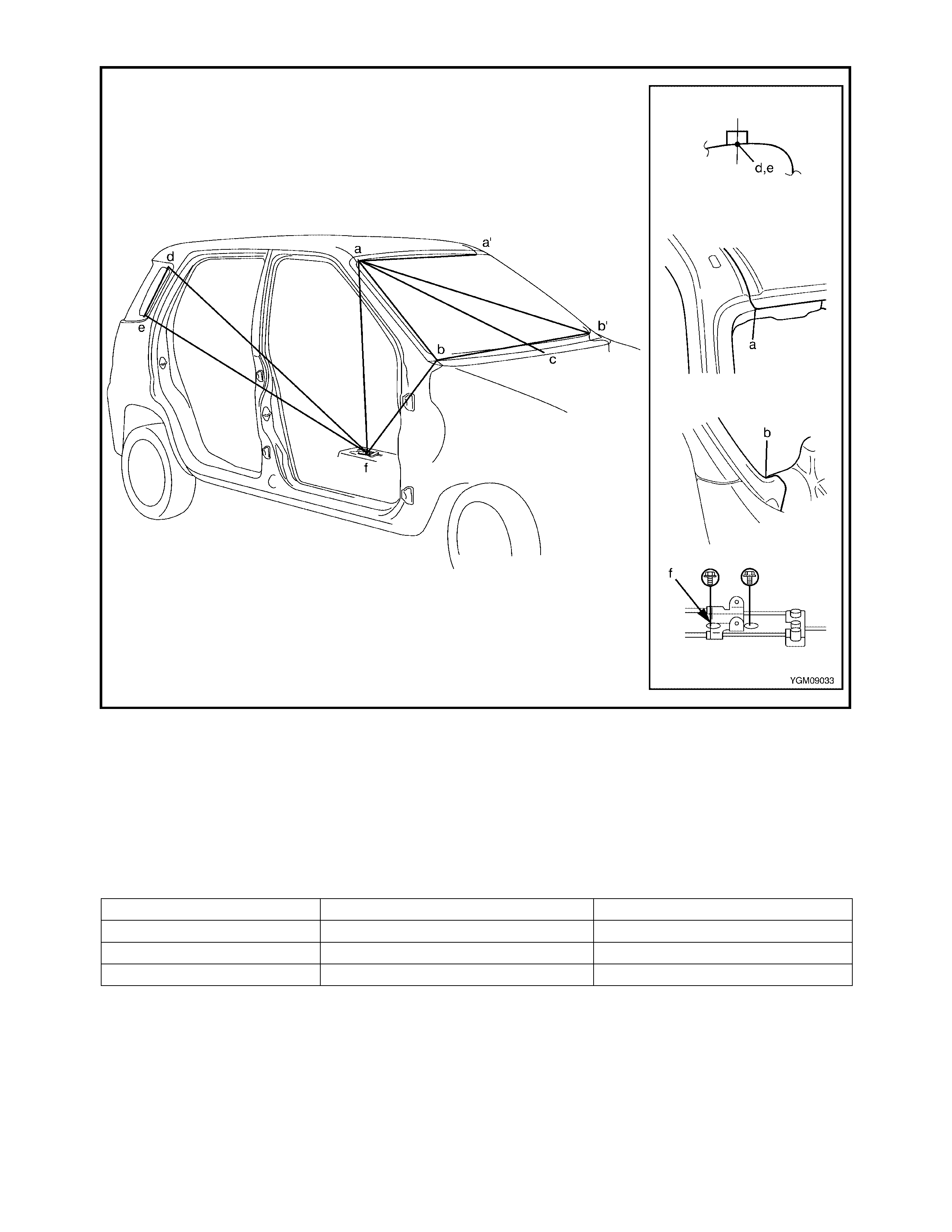
Legend
Hole to hole distance
a
(a’). Front end of front windshield upper installation
section d. Quarter window upper side notch
b (b). Front end of front windshield lower installation
section e. Quarter window lower side notch
c. Garnish installation centre hole (φ5 mm) k. Parking brake cable bracket installation rear
hole
a-a’: 1047 mm a-f: 1282 mm d-f: 1499 mm
a-b: 688 mm b-b’: 1305 mm e-f: 1443 mm
a-b’: 1356 mm b-f: 1411 mm
a-c: 1032 mm d-e: 289 mm
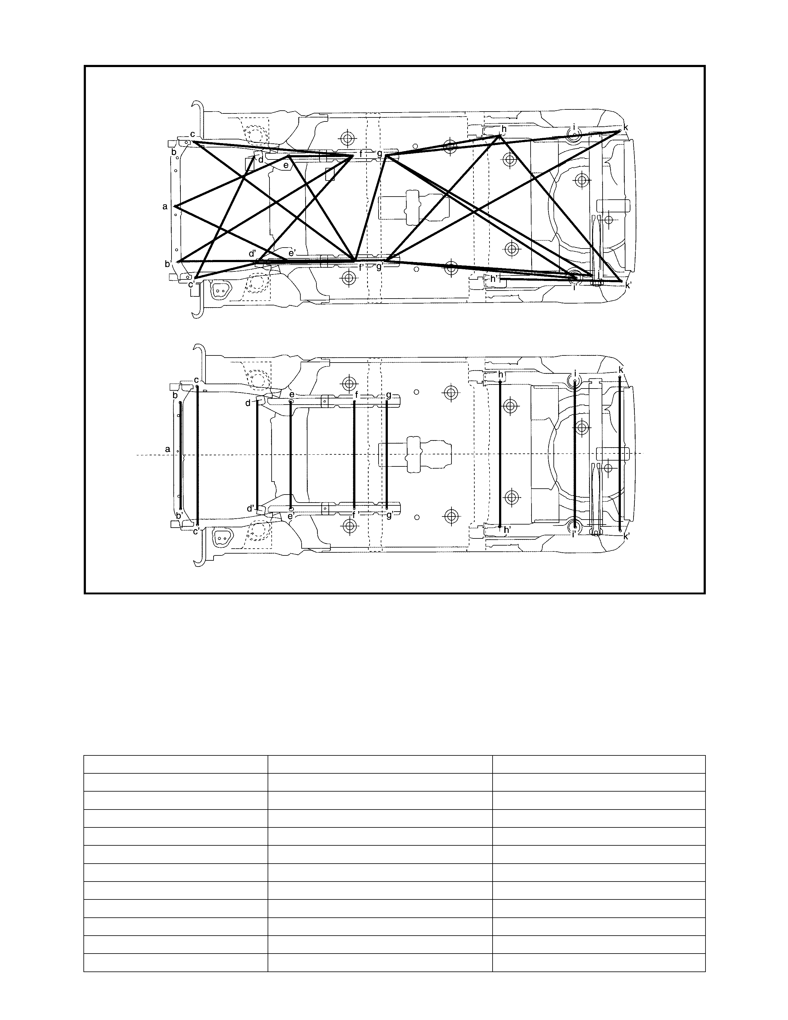
UNDER BODY
Legend
Hole to hole distance
a. Jack bracket installation hole g (g’). Jig hole (φ10 mm)
b (b’). Front stabiliser bracket front installation hole h (h’). Jig hole (φ10 mm)
c (c’). Front stabiliser bracket rear installation hole i (i’). Trailing arm installation hole
d (d’). Suspension control arm installation front hole j (j’). Bump stopper installation hole
e. Rear engine mounting front installation hole k. Lateral rod installation hole
f (f’). Jig hole (φ15 mm) l (l’). Jig hole (φ16 mm)
a-f: 909 mm d’-g’: 708 mm h-k: 1724 mm
a-f’: 862 mm e-g: 702 mm h-l: 1718 mm
b-b’: 740 mm e-g’: 647 mm h’-i: 1204 mm
b’-g: 1464 mm f-f’: 754 mm h’-j’: 1384 mm
b’-g’: 1259 mm f-g: 471 mm h’-k: 1497 mm
c-c: 968 mm f-g’: 889 mm h’-l: 1940 mm
c-g: 1148 mm g-g’: 754 mm i-i’: 1017 mm
c-g’: 1431 mm g’-h: 791 mm i-l’: 1392 mm
c’-d: 970 mm g’-h’: 240 mm i’-l’: 918 mm
c’-d’: 452 mm h-h’: 754 mm j-j’: 1028 mm
d-d’: 761 mm h-i: 826 mm l-l’: 1076 mm
d’-g: 1037 mm h-j’: 1640 mm
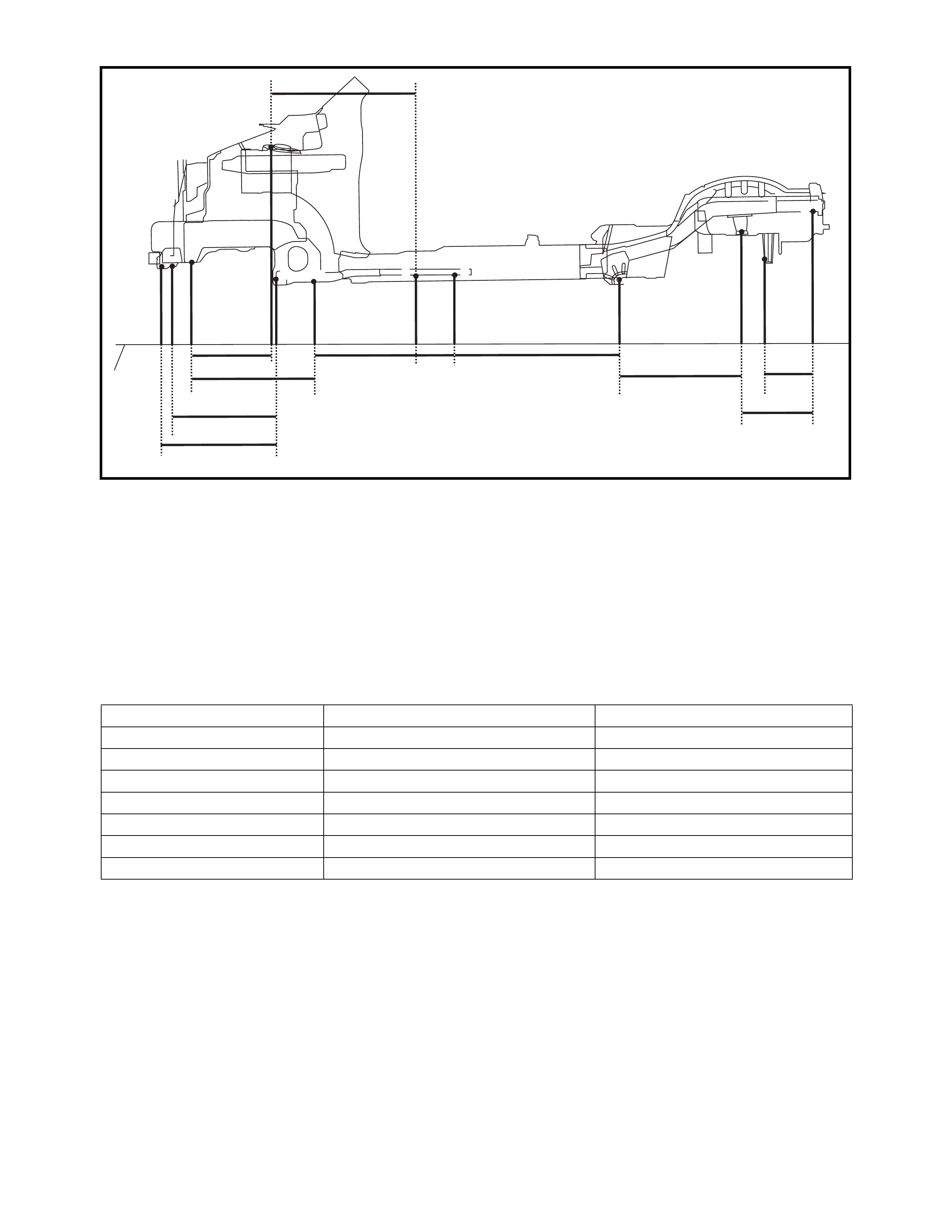
Legend
Point to point distance
d
abcefgh
h’j’
jk
k’l’
l
i’
i
g’f’
e’d’c’b’a’
1
1. Virtual baseline g. Jig hole (φ10 mm)
a. Jack bracket installation hole h. Jig hole (φ10 mm)
b. Front stabiliser bracket front installation hole i. Trailing arm installation hole
c. Front stabiliser bracket rear installation hole j. Bump stopper installation hole
d. Strut installation front hole k. Lateral rod installation hole
e. Suspension control arm installation front hole l. Jig hole (φ16 mm)
f. Jig hole (φ15 mm)
a-a’: 133 mm d’-g’: 749 mm h’-i’: 815 mm
a-e’: 558 mm e-e’: 77 mm i-i’: 85 mm
b-b’: 133 mm e’-f’: 238 mm i’-j’: 546 mm
b’-e’: 550 mm f-f’: 55 mm j-j’: 292 mm
c-c’: 162 mm f’-g’: 470 mm j’-l’: 324 mm
c’-d’: 391 mm g-g’: 80 mm k-k’: 139 mm
c’-e’: 432 mm g’-h’: 240 mm k’-l’: 193 mm
d-d’: 648 mm h-h’: 80 mm l-l’: 375 mm
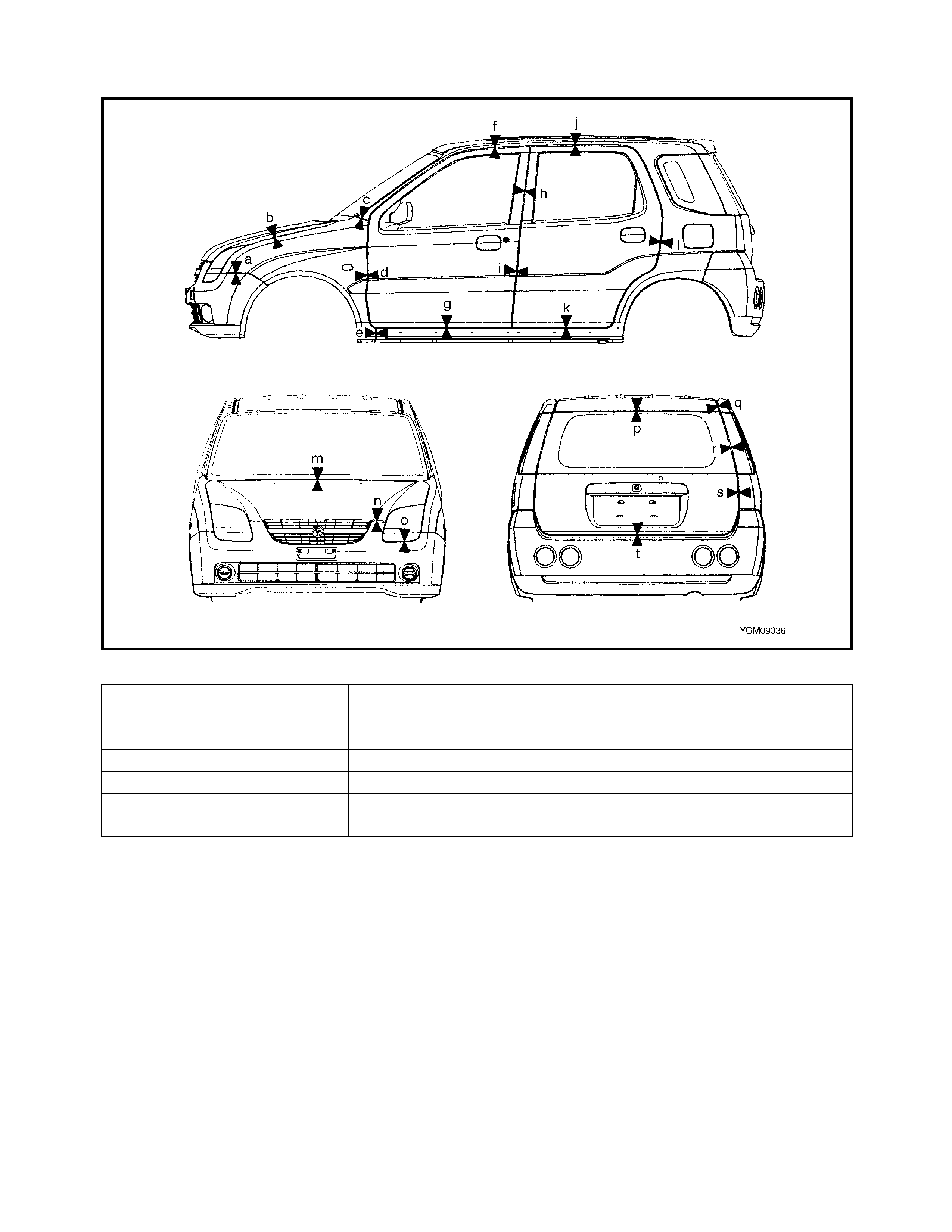
2.17 PANEL CL EARANCE
Panel to panel distanc e
a: 1.5-2.5 mm h: 3.6-5.6 mm o: 3.5-5.5 mm
b: 2.5-3.5 mm i: 4.2-6.2 mm p: 2.6-4.6 mm
c: 1.6-3.6 mm j: 5.0-7.0 mm q: 3.6-5.6 mm
d: 4.1-6.1 mm k: 4.7-6.7 mm r: 4.8-6.8 mm
e: 1.6-3.6 mm l: 3.6-5.6 mm s: 3.7-5.7 mm
f: 5.0-7.0 mm m: 4.8-6.8 mm t: 5.3-7.3 mm
g: 4.7-6.7 mm n: 7.8-9.8 mm
3. INSTRUMENTATION AND DRIVER INF ORM ATION
3.1 INSTRUMENT PANEL
WARNING: See WARNING at the beginning of this sec-
tion.
REMOVAL
1. Disconnect the negative cable at the battery.
2. Disable the airbag system, refer to Section 10B,
3.1 SERVICE PRECA U TIO NS .
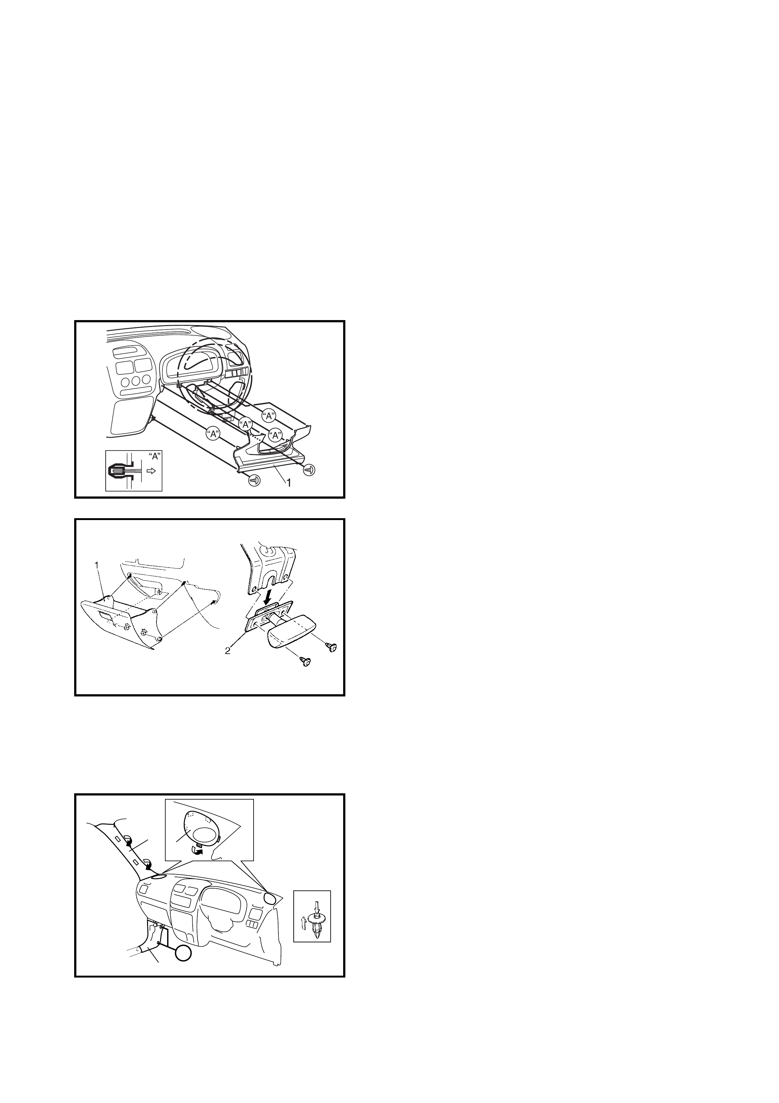
3. Remove the steering column hole cover (1).
4. Remove the glove box (1) and hood latch release
lever (2).
5. Disconnect the instrument panel harness connectors,
antenna and heater control cables.
6. Remove the instrument panel ground wire.
7. Remove the steering column assembly, refer to
Section 3C, 3.6 STEERING COLUMN ASSEMBLY.
8. Remove the front pillar trims (1) and dash side
trims (2).
9. Remove the speaker covers (3).
2“A”
13
“A”
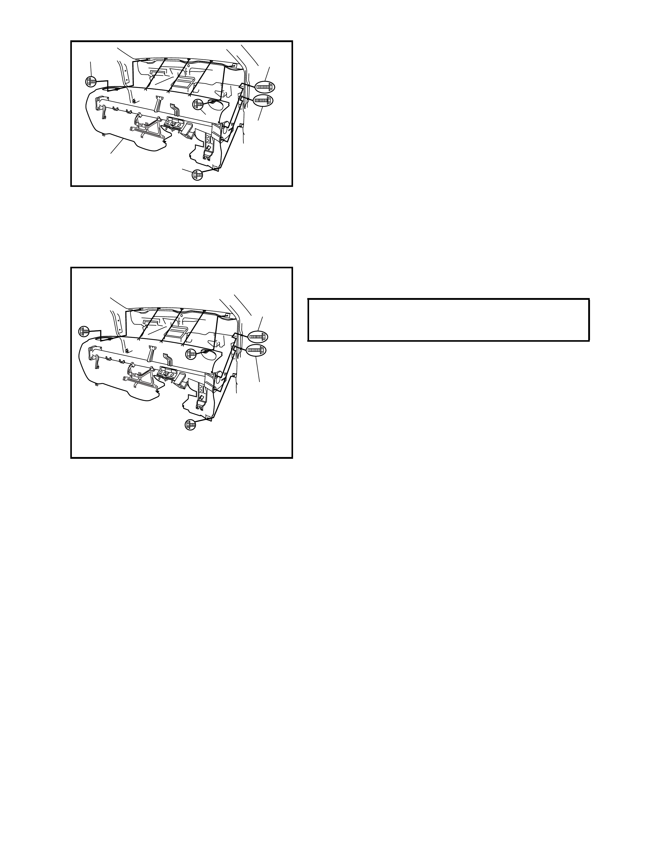
10. Remove the instrument panel mounting bolts (2).
11. Remove the instrument panel (1) with the steering
support member and instrument panel harness.
INSTALLATION
Reverse removal procedure to install the instrument panel
noting the following:
• When installing each part, be careful not to catch any
cable or wiring harness.
• Tighten the instrument panel mounting bolts (1) to the
specified torque.
• When installing the steering column assembly, refer to
3.6 STEERING COLUMN ASSEMBLY in Section 3C.
• Adjust the heater control cables. Refer to Section 1A,
3.4 HEATER CONTROL ASSEMBLY.
• Enable the airbag system if equipped, refer to Section 10B,
3.1 SERVICE PRECAUTIONS.
2
2
2
2
2
1
INSTRUMENT PANEL MOUNTING
BOLTS (a)
TORQUE SPECIFICATION 23 Nm
1, (a)
1, (a)
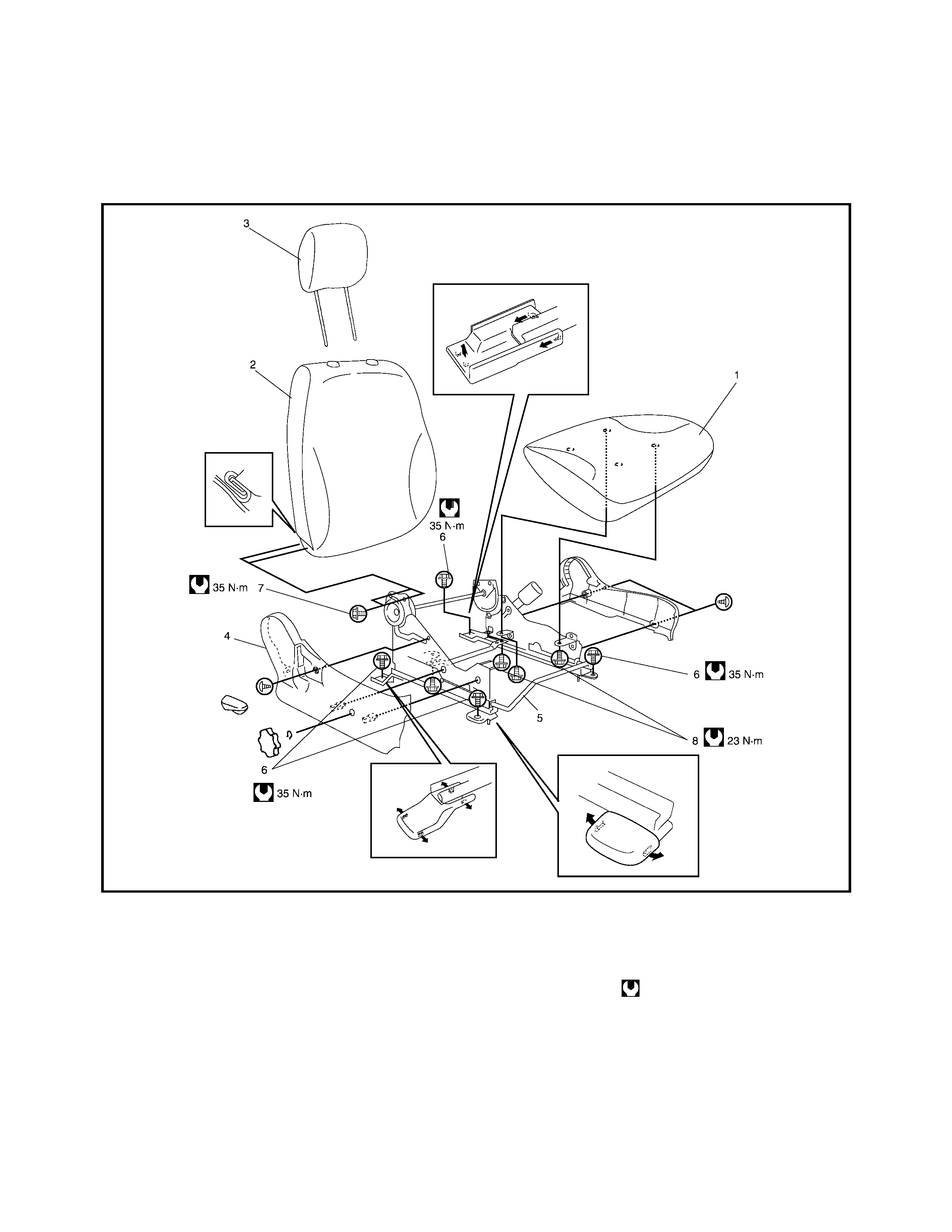
4. SEATS
4.1 FRONT SEAT
Legend
REMOVAL
1. Remove the console box.
2. Remove the four mounting bolts to remove the seat
assembly.
3. Disassemble and repair the seat as necessary.
INSTALLATION
Reverse removal procedure to install the front seat.
Torque to specifications as shown.
1. Seat cushion 4. Side cover 7. Reclining bolt
2. Seat back 5. Seat adjuster (fore and aft) 8. Seat cushion bolt
3. Head rest 6. Seat adjuster bolt Tightening torque
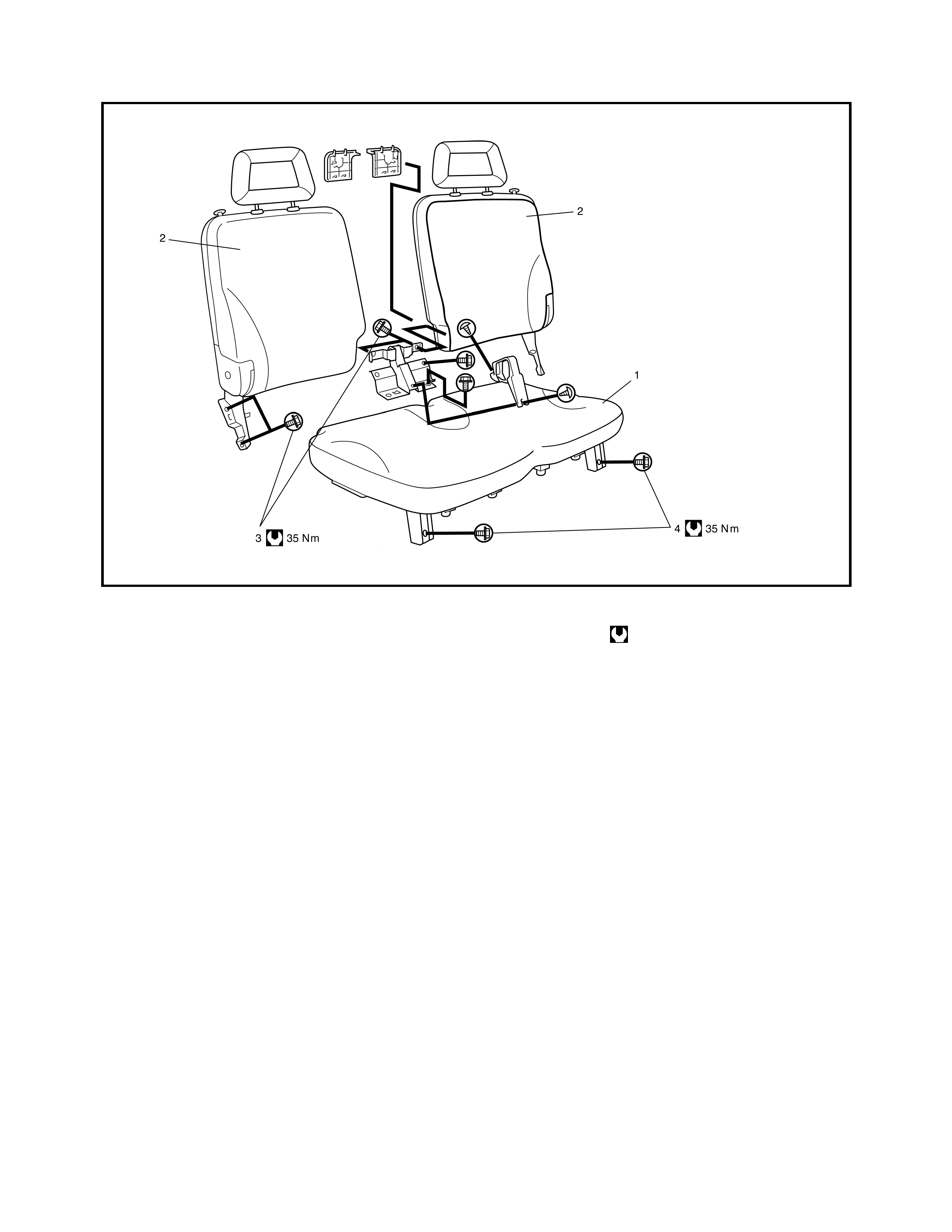
4.2 REAR SE AT
Legend
REMOVAL
1. Remove the two seat cushion bolts (4) to remove the
seat cushion.
2. Remove the three seat back bolts (3) to remove the
seat back.
3. Disassemble and repair the seat as necessary.
INSTALLATION
Reverse removal procedure to install the rear seat.
Torque to specifications as shown.
1. Seat cushion 3. Seat back bolt Tightening torque
2. Seat back 4. Seat cushion bolt
5. SECURITY AND LOCKS
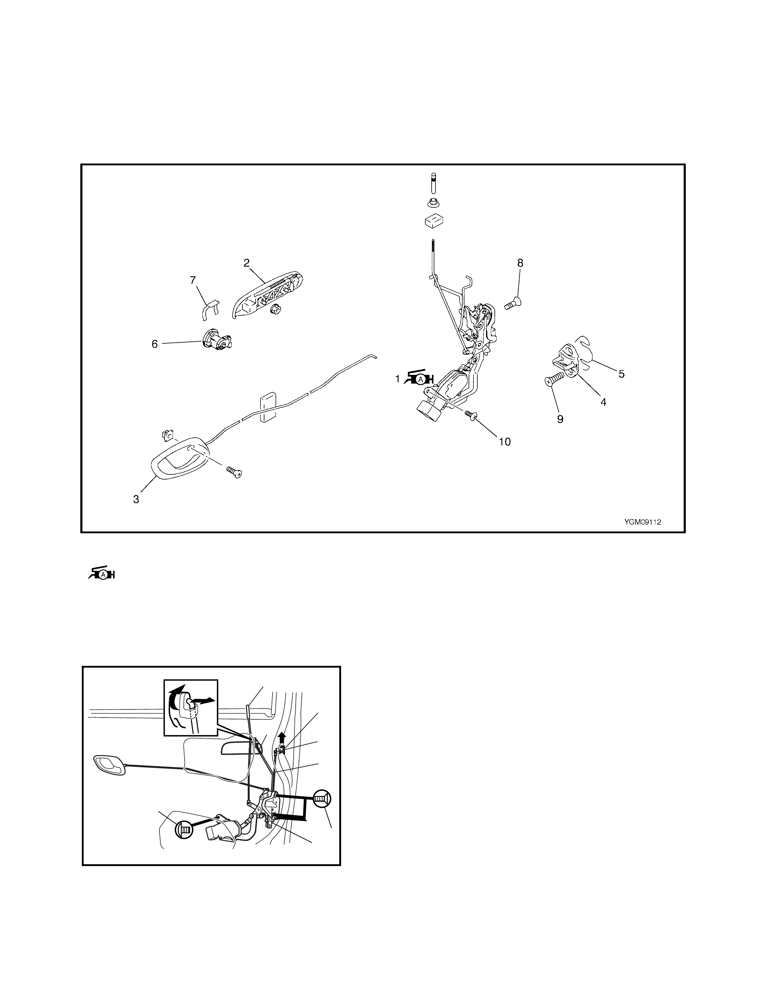
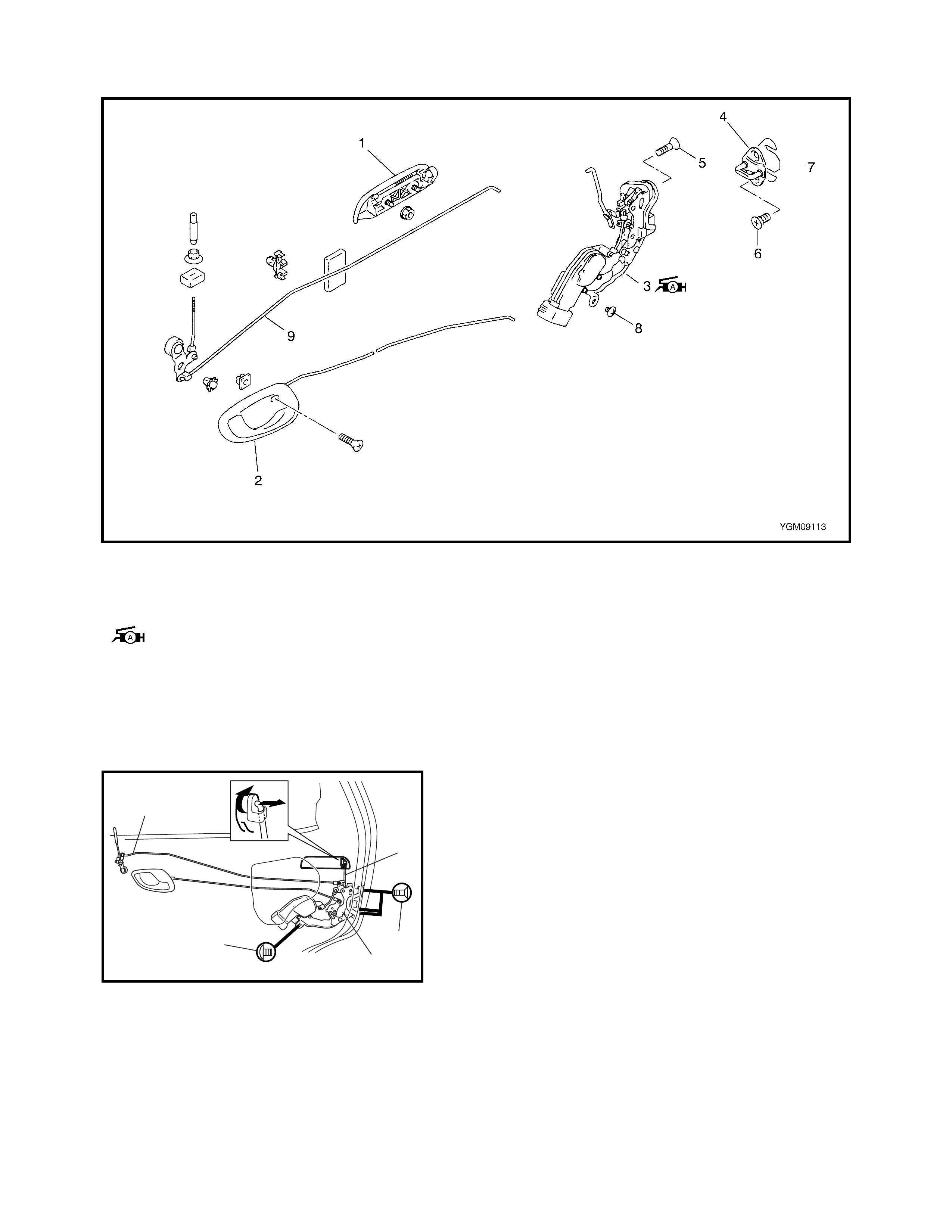
5.1 FRONT DOOR LOCK ASSEMBLY
Legend
REMOVAL
1. Remove the door trim and door sealing cover, refer to
1.1 FRONT DOOR GLASS, REMOVAL in this Section.
2. Raise the window all the way up.
3. Remove the door sash.
4. Disconnect the door opening control rod (1) from the
outside handle.
5. Disconne ct the door latch con tr ol ro d (2).
6. Disconnect the door lock motor lead wire.
7. Remove the door lock knob (3).
8. Loosen the door latch screw (4), door latch actuator
screw (5) and remove the door lock assembly (6).
9. Remove the key cylinder retainer (7).
10. Remove the key cylinder (8).
1. Front door latch assembly
: Apply Lithium grease
to sliding part
3. Inside handle bezel 7. Key cylinder retainer
4. Latch striker 8 . D oo r latch sc r ew
5. Shim 9. Door latch st ri ker scr ew
2. Outside handle 6. Key cylinder 10. Door latch actuator screw
3
1
7
8
2
4
6
5
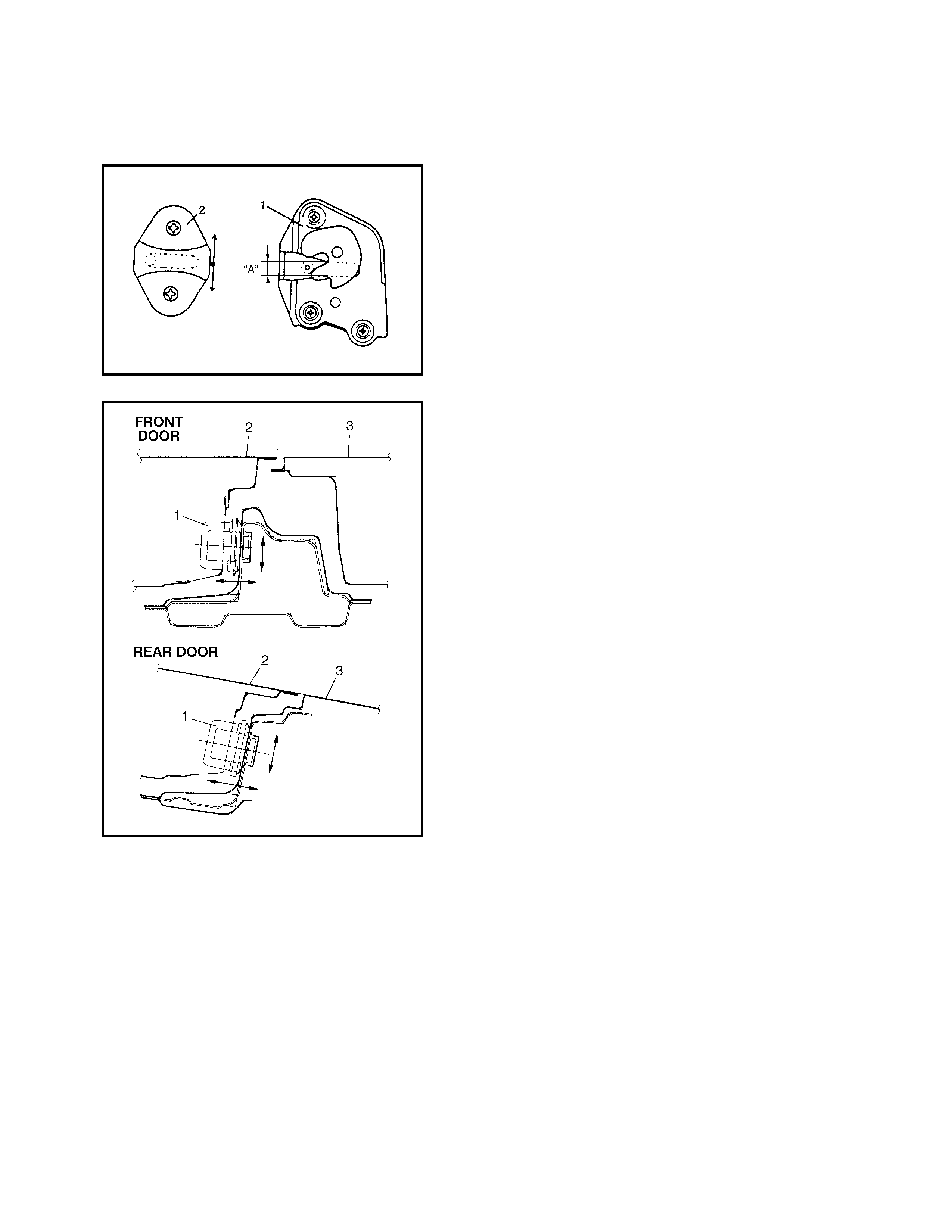
INSTALLATION
Reverse removal procedure to install the front door lock
assembly noting the following:
• Apply grease to the sliding parts of door latch
assembly.
• Move the doo r l atc h st rike r ( 2) up o r do wn s o its ce ntr e
aligns with the centre of groove “A” on the door lock
assembly (1) as shown.
Striker should be moved vertically and placed level. Do
not adjust the door lock.
• Move the door latch striker (1) sideways to adjust the
door outer panel surface (2) to be flush with the rear
door outer panel or body outer panel surface (3) as
shown.
Increase or decrease the number of shims between the
body and latch striker (1) until the door lock operates
correctly.
INSPECTION
Check that the door opens and closes correctly and
smoothly.
Also check that the door latch half lock operates correctly
(check that door latch half lock keeps door from opening all
the way) and that the door latch full lock, locks securely
when closed.
Adjust door latch striker position if necessary.
5.2 REAR DOOR LOCK ASSEMBLY
Legend
REMOVAL
1. Remove the door trim and door sealing cover, refer to
1.4 REAR DOOR GLASS, REMOVAL in this Section.
2. Disconnect the door opening control rod (1) and door
latch control rod (2).
3. Loosen the door latch mounting screw (3), door latch
actuator screw (5) and remove the door lock assembly
(4).
INSTALLATION
Reverse removal procedure to install the rear door lock
assembly referring to 5.1, FRONT DOOR LOCK ASSEMBLY
in this Section.
1. Outside handle 4. Latch striker 7. Shim
2. Inside handle bezel 5. Door latch screw 8. Door latch actuator screw
3. Rear door latch assembly
: Apply Lithium gr ease to
sliding part
6. Door latch striker screw 9. Door lock control rod
2
1
3
4
5
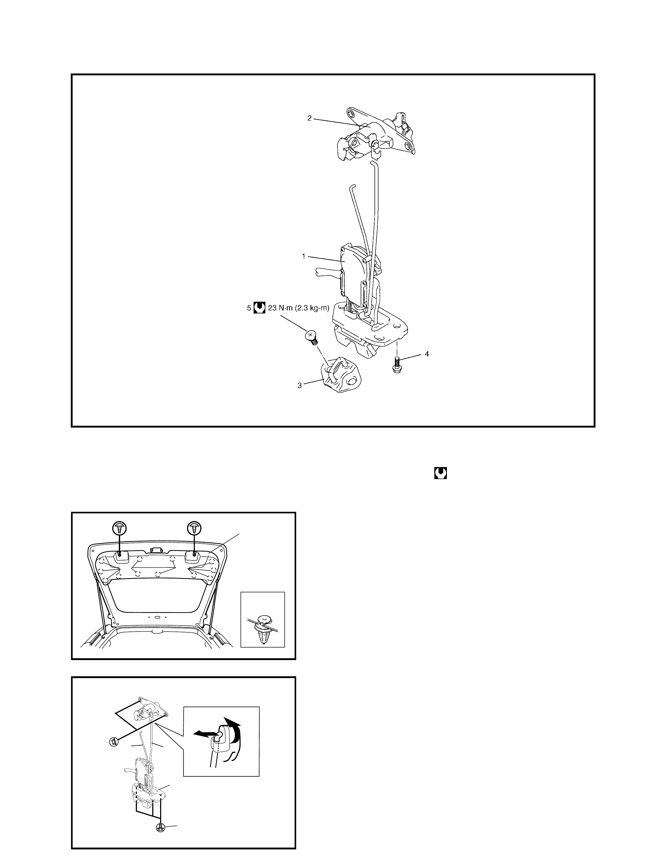
5.3 BACK DOOR LOCK ASS EMBLY
Legend
REMOVAL
1. Remove the door trim (1).
2. Disconnect the door lock control rod (1).
Disconnect the control rod (2).
3. Disconnect the door lock motor lead wire.
4. Loosen the door latch screw (3) and remove the door
latch asse mbl y (4 ).
1. Back door latch assembly 3. Latch striker 5. Latch striker screw
2. Back door lock cylinder 4. Door latch screw Tightening torque
“A”
“A”“A”
1
21
4
3
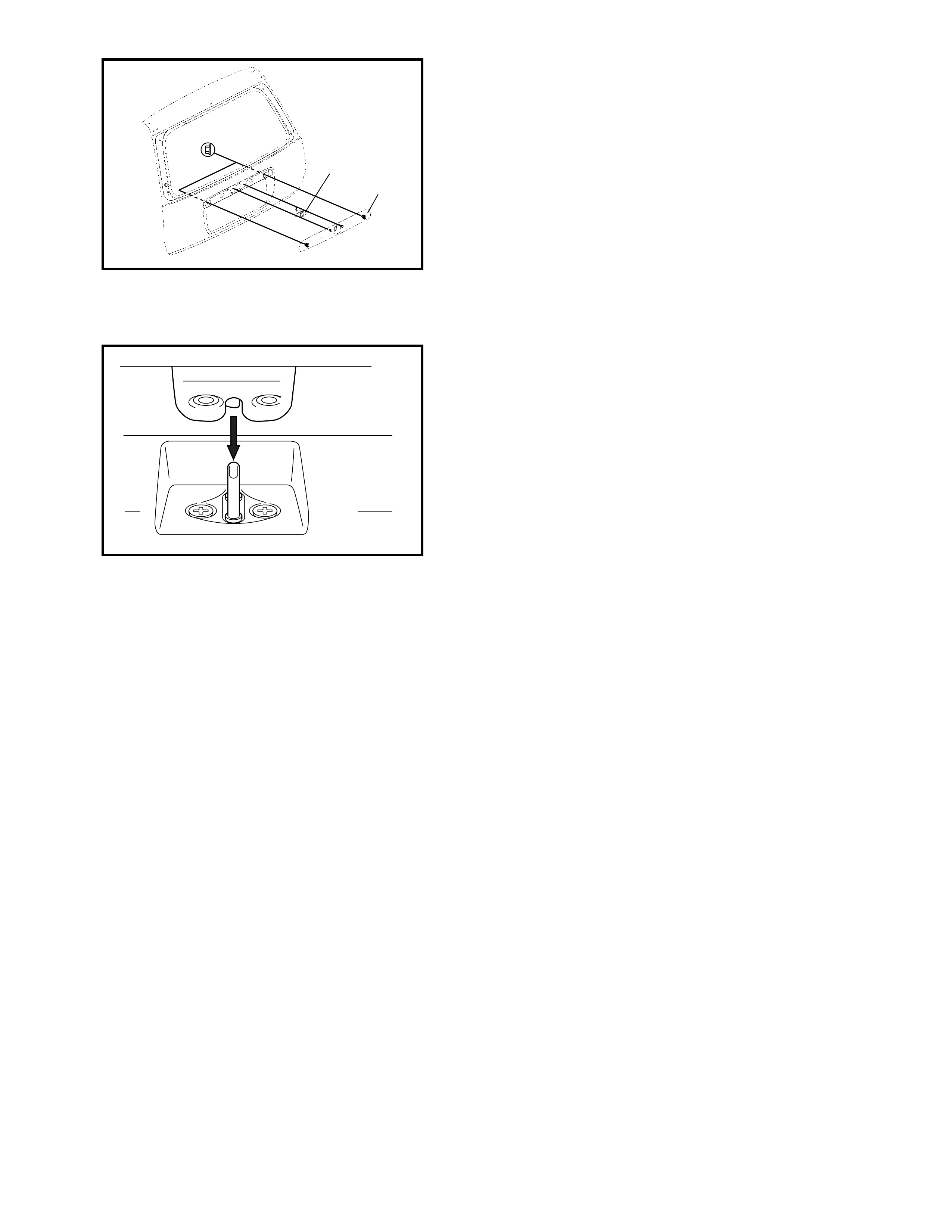
5. Remove the back door licence garnish (1).
6. Remove the back door lock cylinder (2).
INSTALLATION
Reverse removal procedure to install the back door lock
assembly noting the following:
• Adjust the door latch striker so that its centre aligns
with the centre of the groove in the door latch base.
INSPECTION
Check that the door open and closes correctly and
smoothly.
Also check that the door latch half lock operates properly
(Check that door latch half lock keeps door from opening all
the way) and the door latch full lock, locks securely when
closed.
Adjust the door latch striker position if necessary.
5.4 KEY CODING
KEY USAGE AND IDENTIFICATION
The Key is used for the ignition and the door lock cylinders.
Keys are cut on both edges to make them reversible.
Key identification is obtained from the five character key
code stamped on the key code tag. Using this key code,
the key code cutting combination can be determined from a
code list (available to owners of key cutting equipment).
If the key codes are not available from records or tags, the
key code can be obtained from the right hand door lock cyl-
inder (if lock has not been replaced). Lock cylinders sup-
plied as service parts are unmarked.
If the original key is available, key code cutting combination
can be determined by copying key.
IGNITION SWITCH CYLINDER LOCK
REMOVAL AND INSTALLATION
Refer to 3.7 STEERING LOCK ASSEMBLY (IGNITION
SWITCH) in Section 3C.
ELECTRICAL DIAGNOSIS
For ignition switch electrical troubleshooting refer to
Section 8, 2.9 IGNITION SWITCH.
2
1
6. EXTERIOR AND INTERIOR TRIM
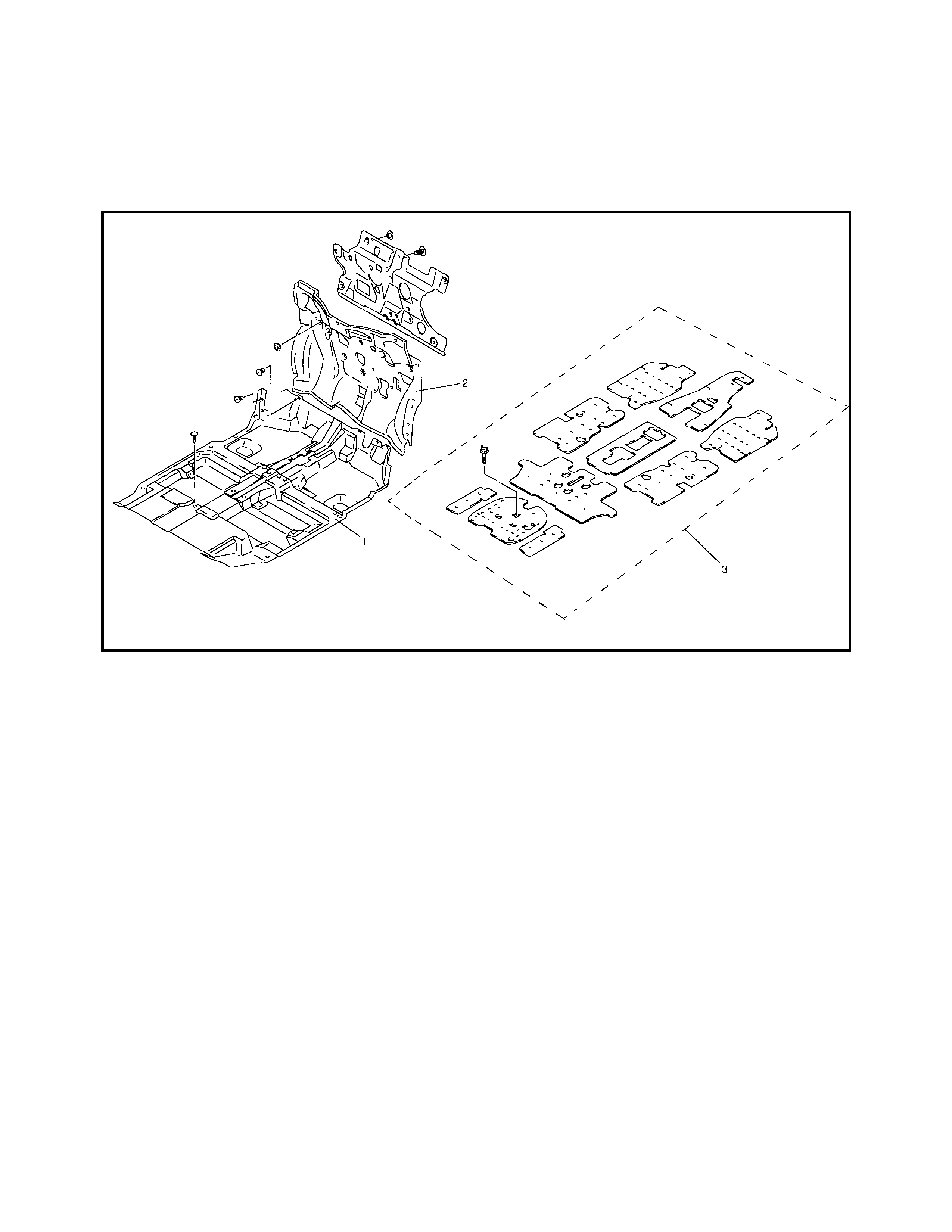
6.1 FLOOR CARPET
Legend
REMOVAL
1. Remove the front seats and rear seat cushion, refer to 4.1., FRONT SEAT and 4.2, REAR SEAT in this
Section.
2. Remove the seat belt lower anchor bolt, refer to Section 10, 3.2 FRONT SEAT BELT ASSEMBLY.
3. Remove the dash side trims, front side sill scuffs, centre pillar inner lower trims, quarter inner trims and
rear side sill scuffs.
4. Remove the parking brake lever cover and console box.
5. Remove the floor carpet.
INSTALLATION
Reverse removal sequence to install the front floor carpet, noting the following instruction.
• For tightening torque of seat belt anchor bolt, refer to Section 10, 3.2 FRONT SEAT BELT ASSEMBLY.
1. Floor carpet 2. Dash panel silencer 3. Silencer seat
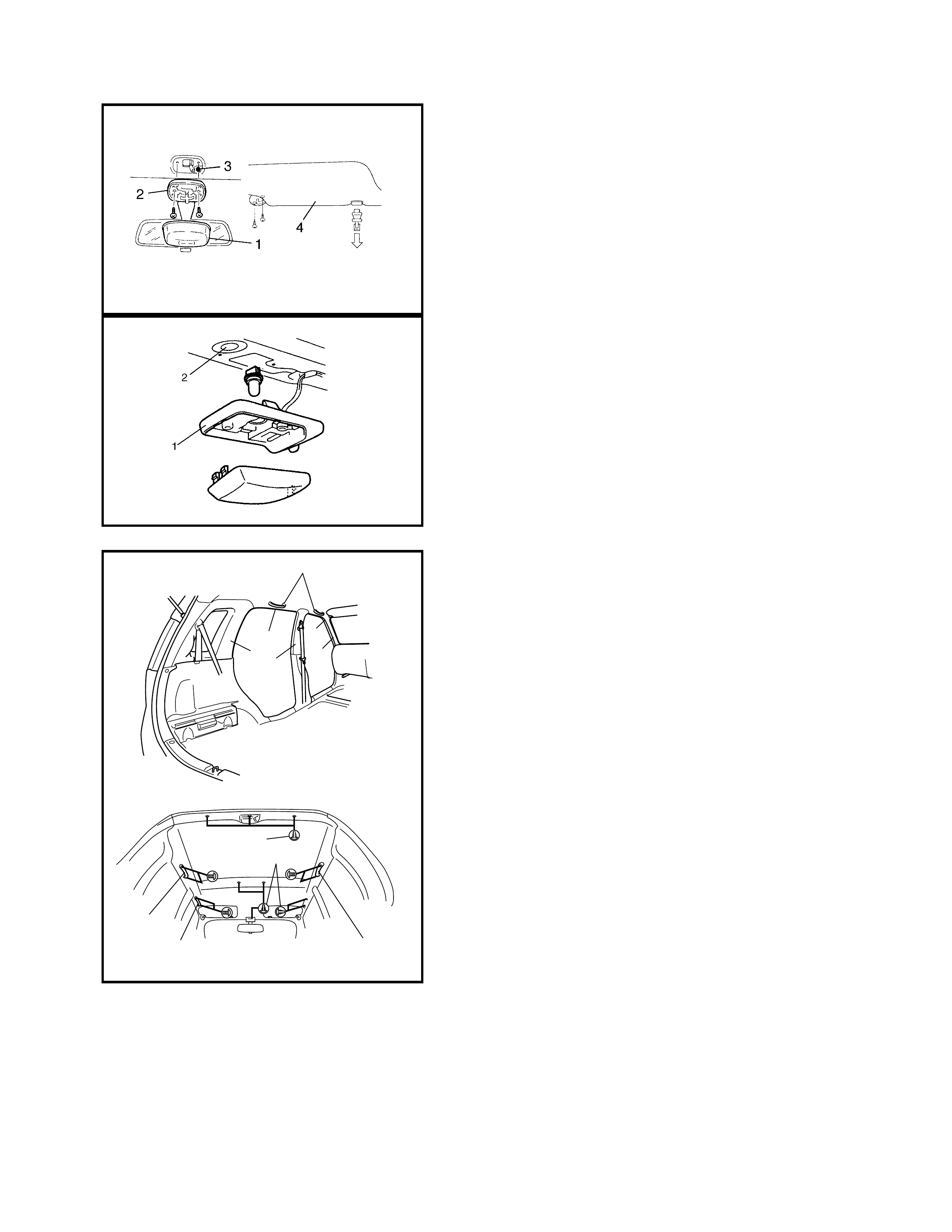
6.2 HEADLINING
REMOVAL
1. Unclip interior light cover (1).
2. Remove the interior light (2) 2 screws.
3. Remove the headlining clip (3).
4. Remove the sun visor (4).
5. Unclip the luggage room light (1).
6. Remove the headlining clip (2).
7. Remove the assistant grip (1).
8. Remove the door opening trim (2) and unclip the upper
section of the inside trims covering the headlining (3).
9. Remove the headlining clips (4) and remove the head
lining.
NOTE: Adhesive is used to attach headlining.
Clean the adhesive from the headlining and the roof after
removing the headlining.
1
11
44
1
223
3
3
YGM09097
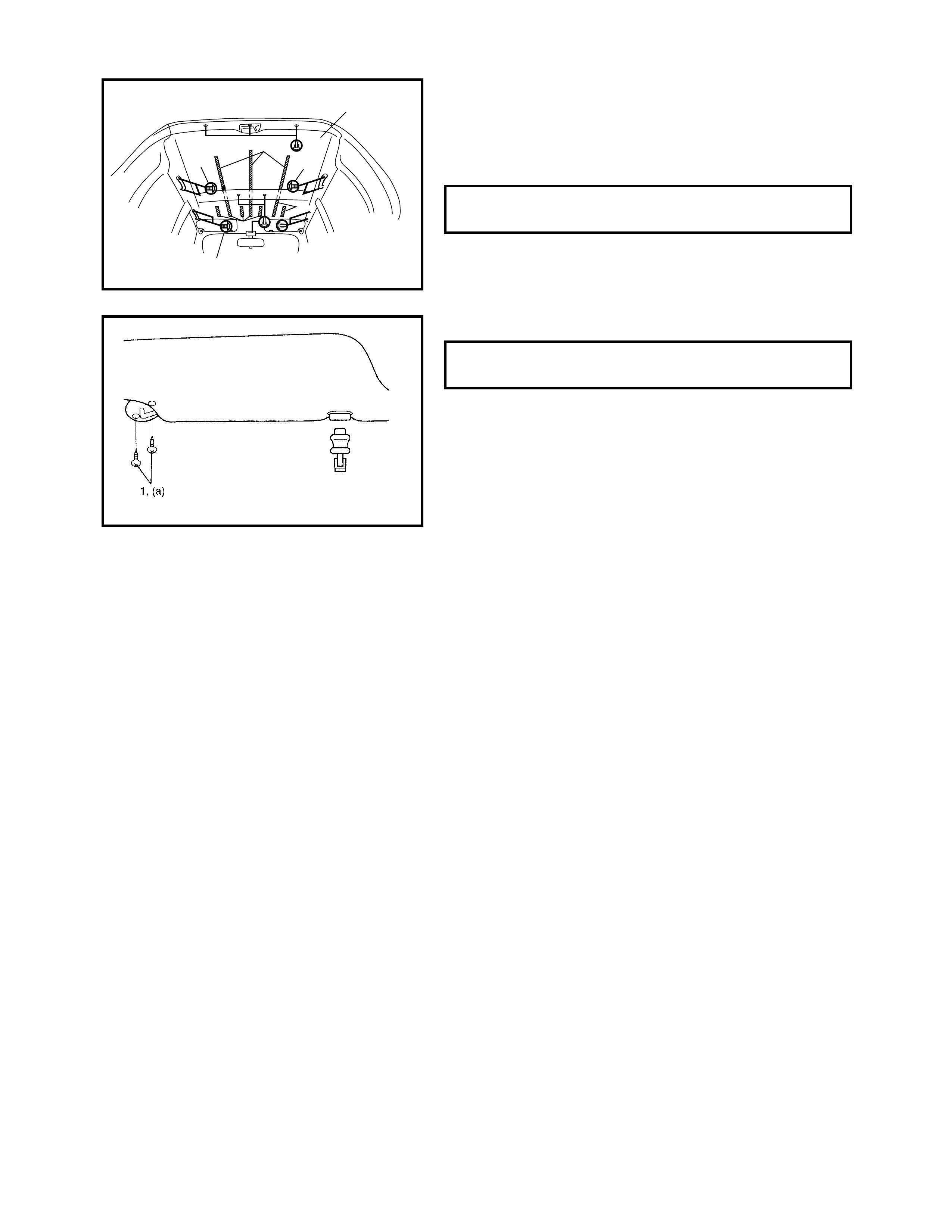
INSTALLATION
Reverse r emoval proced ure to install the headlining notin g
the following:
• Apply double-sided tape (1) to the headlining (2) as
shown in figure then install the headlining (2).
• Tighten the assistant grip screw (3) to specified torque.
• Tighten the sun visor screw (1) to specified torque.
ASSISTANT GRIP SCREW
TORQUE SPECIFICATION 4 Nm
1
1
1
3
33
2
SUN VISOR SCREW (a)
TORQUE SPECIFICATION 4 Nm

7. PAINT AND COATINGS
7.1 ANTI-CORROSION TREATMENT
WARNING: Standard shop practices, particularly eye protection, should be followed during the per-
forming the operations below to avoid personal injury.
To improv e th e c or rosi on res is tance of the body st ru ctu re, one or tw o side d gal v ani se d st eel she et i s used . In
addition, the following anti-corrosion measures are used:
• Steel sheets are treated with cathodic electroprimer which has excellent corrosion resistance.
• Rust proof wax coatings are applied to the inside of doors and side sills where moisture is likely to remain.
• Vinyl coating is applied to the underside of the body and to the inside of the wheel housing.
• Sealant is applied to door hems and panel joints to prevent water penetration and resulting rust.
When panels are replaced or there is collision damage repair, leaving the relevant area unt reated will leave
the area s usceptib le to cor rosion . There fore, it i s an es senti al func tion o f a ny repair operat ion to cor rectly re-
coat the relevant surfaces.
All metal panels are coated with metal conditioners and primer coating during vehicle production. Following
repair and/or replacement part installation, every accessible bare metal surface should be cleaned and coated
with rust proof primer. Perform this operation prior to the application of sealant and rust proof wax coating.
Sealan t is a ppl ied to t he s pec i fic joints of a v eh ic le durin g pr od uc tio n. T he se al ant is int ended to pr ev ent dus t
from ente ring the veh icle and also serves as an anti- corrosion bar rier. The seala nt is applied to the do or and
hood hem areas and between panels and must be correctly resealed if damaged. Reseal the joints of new
replacement panels and reseal the hem area of a replacement door or hood skins.
Use a quality sealant to seal flanged joints, overlapping joints and seams. The sealant must have flexible
characteristics and be able to be painted after it is applied to repaired areas.
Use caulking material to seal op en joints. Select the correct sealant for the situation and the purpose for its
use. Observe the manufacturer’s instructions when using the sealant.
In m any instances, wh ere repaired sectio ns requir e painting, fo llow the n ormal tech niques fo r finish prepara-
tion, colour painting and undercoating build-up.
Rust proof wax, a penetrative compound, is applied to metal-to-metal surfaces (inside doors and side sills)
where i t is di fficult t o use no rm al u nde rc oa tin g met hod s. S el ec t the cor r ect, pe netr at iv e rus t pr oof w ax f or this
application.
When undercoating (vinyl coating) underbody areas, care should be taken to keep engine related parts, shock
absor ber mo unts and mov ab le parts free fro m se al ant. Fo ll owin g un der -co ati ng, e ns ure tha t body dr ai n ho les
remain open.
The correct sequence for the application of anti-corrosion materials is as follows:
1. Clean and prepare the metal surface.
2. Apply primer.
3. Apply sealant (all joints original ly sealed).
4. Apply colour in areas where colour is required such as hem flanges, exposed joints and under body
components.
5. Apply anti-corrosion compound (penetrative wax).
6. Apply undercoating (rust proof material).
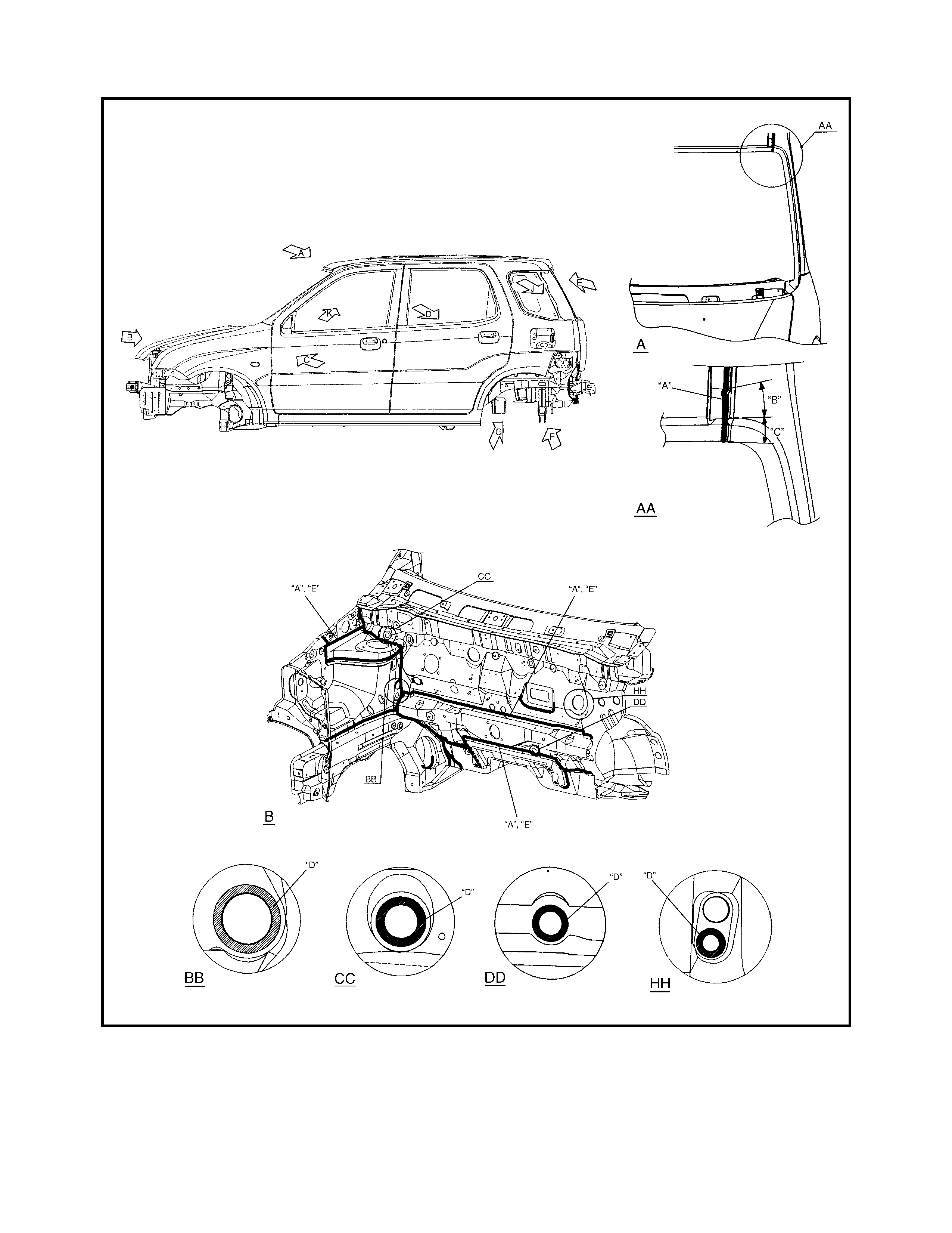
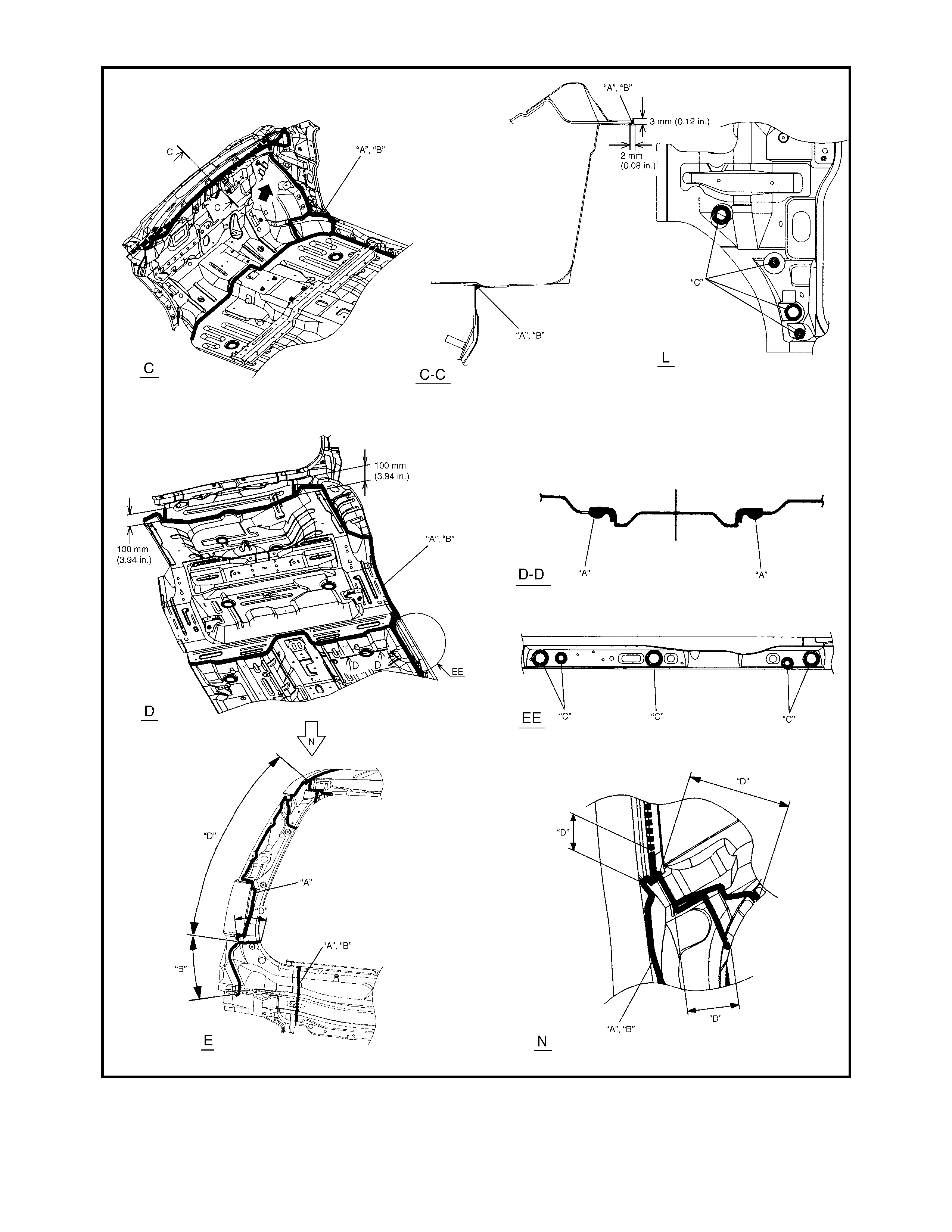
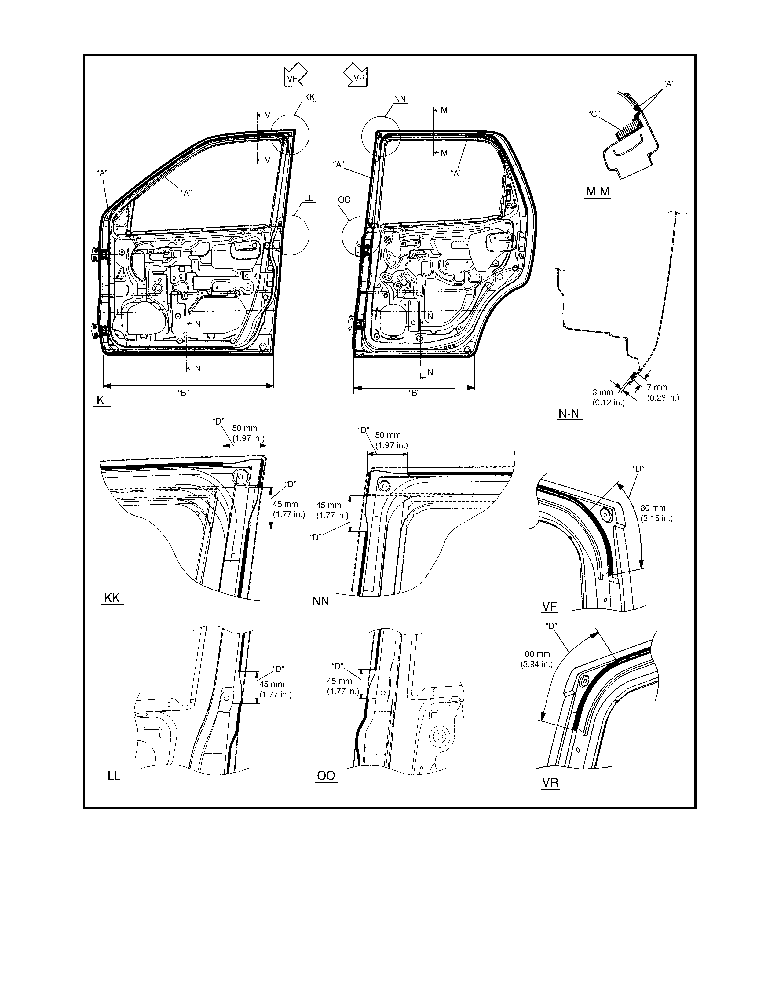
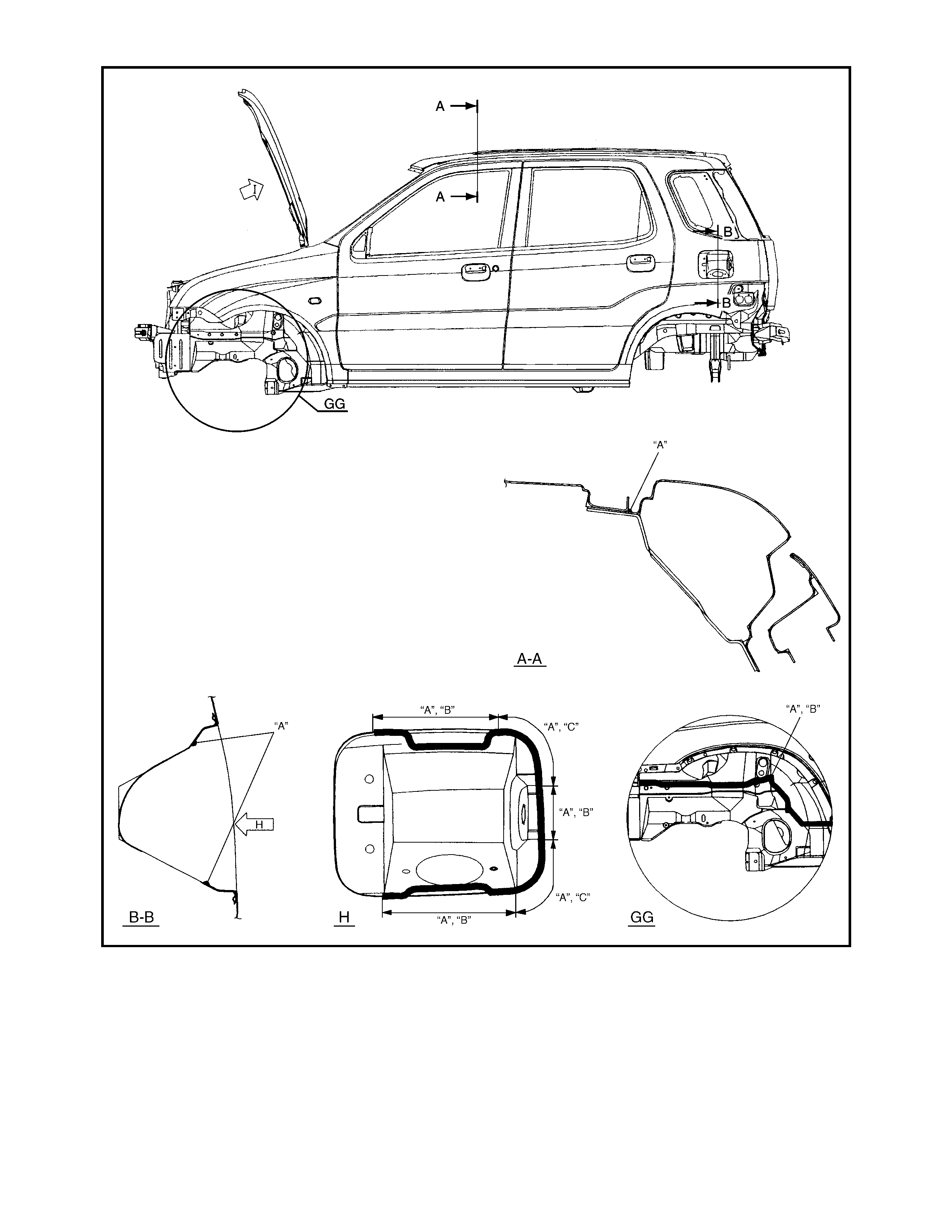
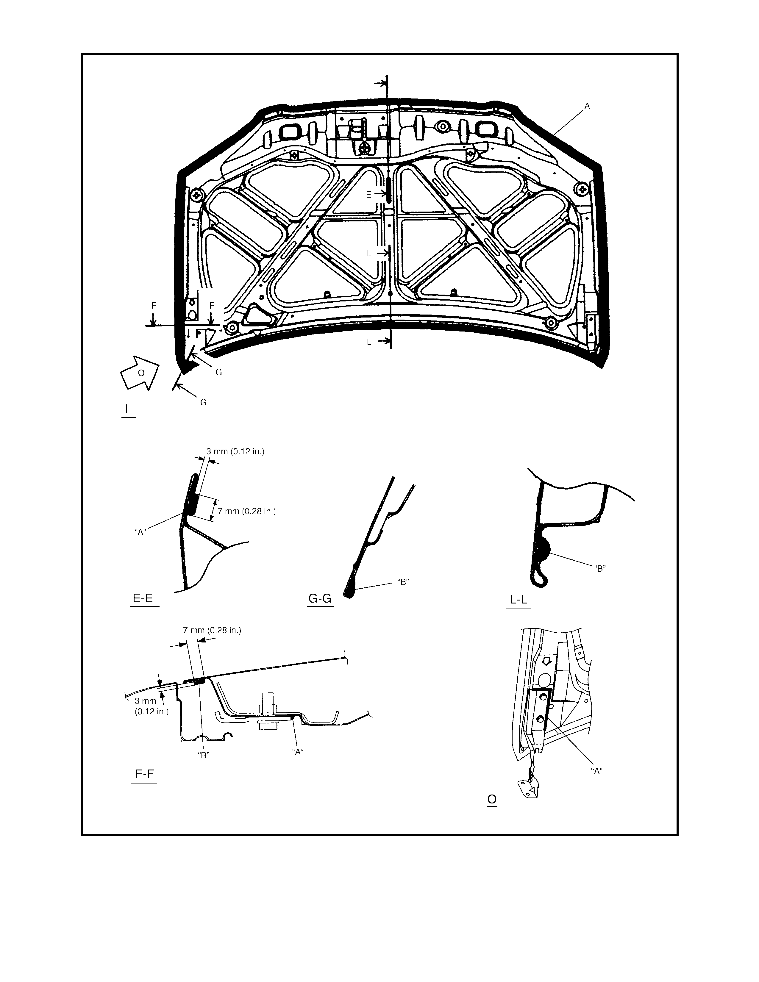
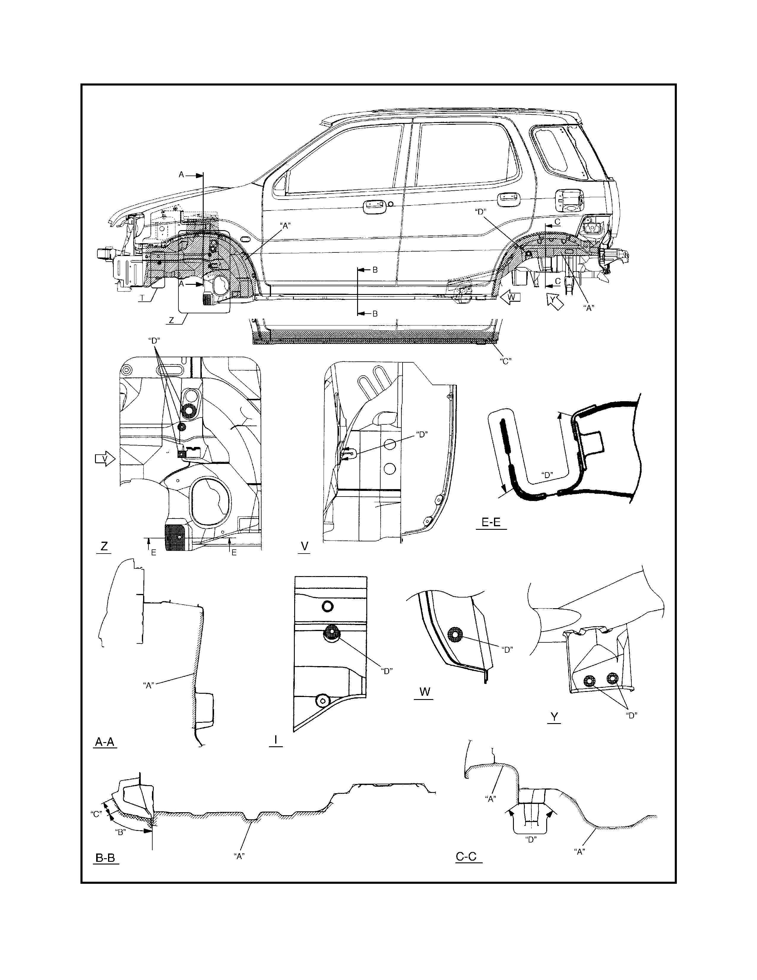
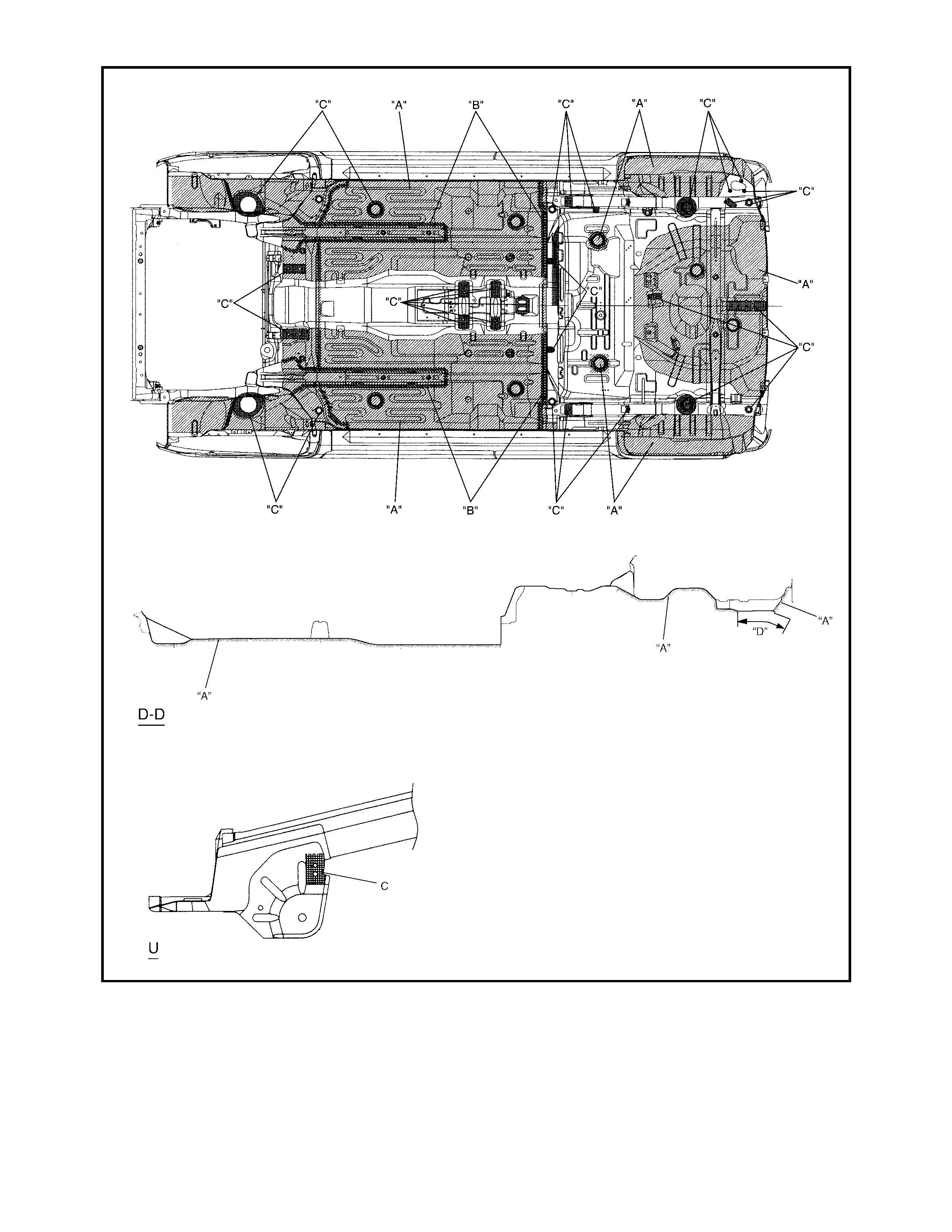
7.2 SEALANT AP PLICATION AREAS
Legend
“A” : Apply sealant “C” : Wipe off excess sealant after
application “E” : Smooth out sealant with a
brush
“B” : Apply sealant without heeling “D” : Do not apply sealant
Legend
“A” : Apply sealant “C” : Do not apply sealant “D” : Wipe off excess sealant after
application
“B” : Smooth out sealant with
a brush
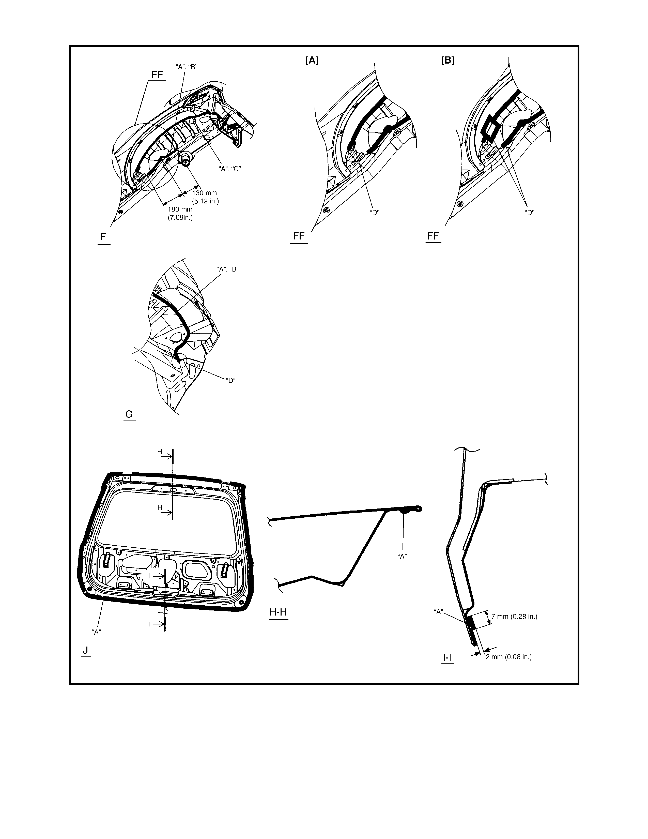
Legend
“A” : Apply sealant “B” : Wipe off excess sealant
after application “C” : S mooth out sealant with a brush
“D” : Fill gap/hole with sealant
Legend
“A” : Apply sealant “C” : Keep hatched area free from
sealant “D” : Wipe off excess sealant
after application
“B” : Never fill up drain holes with
seala nt
Legend
“A” : Apply sealant “B” : Smooth out sealant with a
brush “C” : Wipe off excess sealan t
after application
Legend
“A” : Apply sealant “B” : Apply sealant so that top of
flange is covered
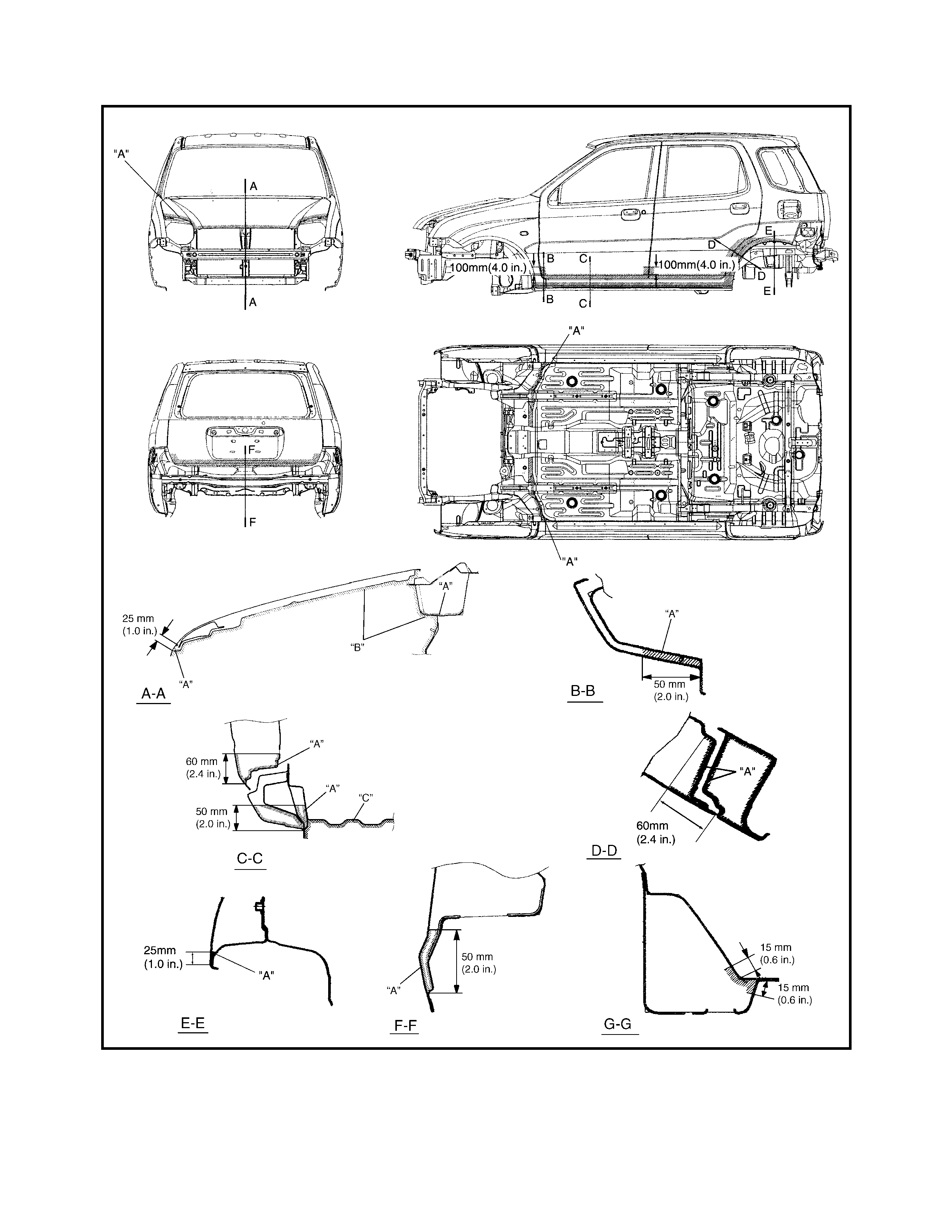
7.3 UNDER COAT ING APPLICATION AREAS
Legend
“A” : Apply undercoating (PCV,
400 µm or more) “B” : Apply anti-chip coat (100 µm
or more) “C” : Apply anti-chip coat (300
µm or more)
“D” : Do not apply undercoating
Legend
“A” : Apply undercoating (PCV,
400 µm or more) “B” : Apply undercoating (PCV,
600 µm or more) “C” : Do not apply undercoating
7.4 ANTI-CORR OSION COMPOUND APPLICATION AREA
Legend
“A” : Apply rust proof wax (hot
wax 50 µm or more) “B” : Apply rust proof wax (low
viscosity wax 10 µm or
more)
“C” : Apply rust proof wax (high
viscosi ty w ax 50 µm o r m ore )
PLASTIC PARTS FINISHING
Paintable plastic parts are made from ABS or PP plastic.
PAINTING
Plastic parts may require priming with specific plastic primer. Refer to your paint manufacturer for further infor-
mation.
1. Parts that require painting should be washed with cleaning solvent.
1. Apply plastic primer to the part in accordance with the paint manufacturer’s directions
2. Apply colour lacquer to the part in accordance with the paint manufacturer’s directions.
3. Follow directions for required drying times. REFERENCE
Plastic parts are identified in an inconspicuous area.
8. REQUIRED SERVICE MATERIAL
Material Recommended product Use
Lithium grease Lithium grease • Window regulator
• Door hing e
Sealant Three Bond No. 1215 • Hood hing e
• Door hing e