
GM POWERTRAIN
VR, VS, VT, VX & VU SERVICE REPLACEMENT TRANSMISSION ASSEMBLY (SRTA) PROGRAM
DL 22/96
March 26, 1996
As a cus tomer satisfac tion initiative, GM-Powertrain in conj unction with Holden has developed a VR/VS/VT Service
Replacement Transmission Assembly (SRTA) Program. This program replaces the existing VR & VS Holden
Warranty Transmission Changeover Program, refer to DL 39/95. Distribution of SRTA units will be through the
existing changeover program distributors. A list of these distributors is provided with this letter.
This program commenced on April 1, 1996.
SRTA transmissions are remanufactured at a single point site in a production environment under strict quality
control conditions.
SRTA distributors are committed to the next business day dispatch for all SRTA models on an FOC (Free of
Charge) basis.
Note:
Transmission orders received early in the day will be dispatched on the same day to Dealers within the
metropolitan area.
GENERAL GUIDELINES
The SRT A Program will operate on a sim ilar basis to the pr evious program in that transm issions will be supplied to
Dealers on an FOC basis.
This SRTA Program is restricted to warranty related transmission failures. Under no circumstances are STRA
transmissions to be used for vehicles outside the new vehicle powertrain warranty period of 100,000 k m or thr ee ( 3)
years.
In the event that the transmission fails and requires replacements on a vehicle with less t han 5,000 km , the Dealer
is to order a new replacement transmission from the local SRTA Distributor.
Dealers should order a SRTA replacem ent transmiss ion for all warranty repairs between 5,000 and 100,000 k m that
cannot be corrected by replacement of parts listed in the on-vehicle service components list. Holden strongly
recommends the use of the SRTA Program for all transmission warranty repairs that fall into the above criteria.
In summary, the on-vehicle service components consist of:
Components that are accessible external to the transmission.
Seals and gaskets for external oil leak repairs excluding torque converter and oil pump seal.
SRTA - ORDERING PROCEDURE
The transmission complaint must be confirmed using the correct diagnosis as detailed in the Diagnosis section of
this letter.
If the repair cannot be carr ied out by replacement of on-vehicle ser vice com ponents, the Dealer will order an SRT A
transmission from the local SRTA Distributor.
All SRTA orders should be faxed to your local Distributor using a completed copy of the SRTA
Order Form (Form F). Transmissions will not be supplied unless the Distributor receives a fully completed SRTA
Order Form.
DIAGNOSIS
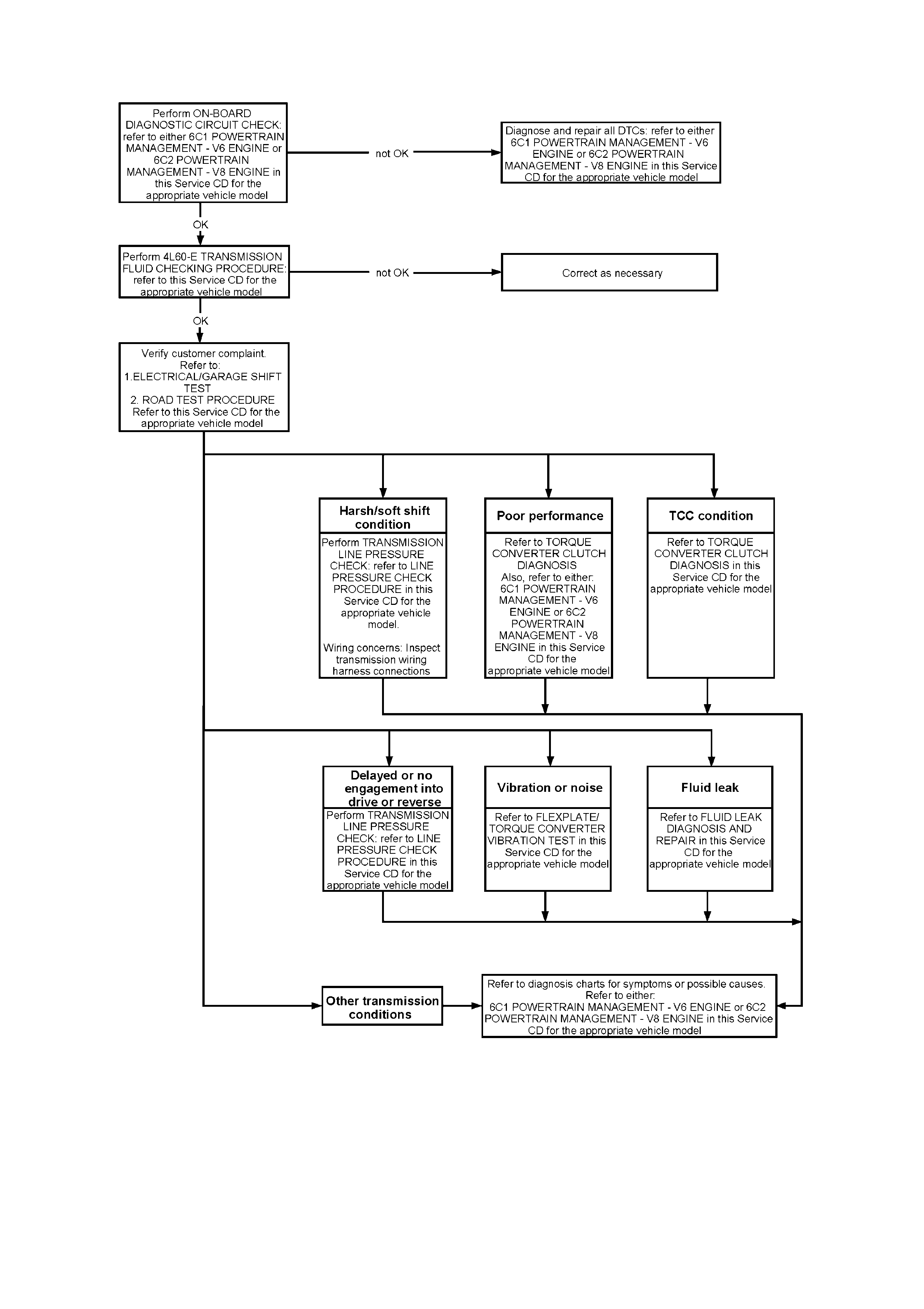
W hen diagnos ing transm ission com plaints, Dealers mus t first c arry out a transm ission f unctional tes t as detailed in
the appropriate section of the Service Information CD. This test procedure is reproduced at the rear of this
document, refer Transmission Function Check.
Technicians must carry out transmission line pressure checks where indicated in the transmission functional test
procedure. The line pressure checking procedure is reproduced at the rear of this document, refer
Line Pressure Check.
Transmission problems can often be attributed to poor electrical connections at the transmission electrical
connector. Guidelines for checking and servicing this connector are provided at the rear of this document, refer
Transmission Electrical Connector.
PlDL 40/00
SRTA - MODEL INFORMATION
Model
Type SRTA Part
Number Description Vehicle Range
4HBD 8688982 VR 5.0L floor shift VR SOP to L778496 (22/11/94)
4HDD 8688983 VR 3.8L floor shift VR SOP to L772125 (2/11/94)
5HBD 24202441 VR/VS 5.0L floor shift L778497 (22/11/94) to
L871025 (17/10/95)
5HCD 24202442 VR 3.8L column shift L772868 (4/11/94) to VS SOP
5HDD 24202443 VR 3.8L floor shift L772126 (2/11/94) to VS SOP
5HSD 24203290 VR/VS 5.7L HSV From L756483 (12/9/94) to
L826471 (6/10/95)
6HDD 24203402 VS 3.8L floor shift From VS SOP
6HCD 24203403 VS 3.8L column shift From VS SOP
6HBD 24203404 VS 5.0L floor shift From L871026 (17/10/95)
6HSD 24203405 VS 5.7L HSV From L826472 (6/10/95)
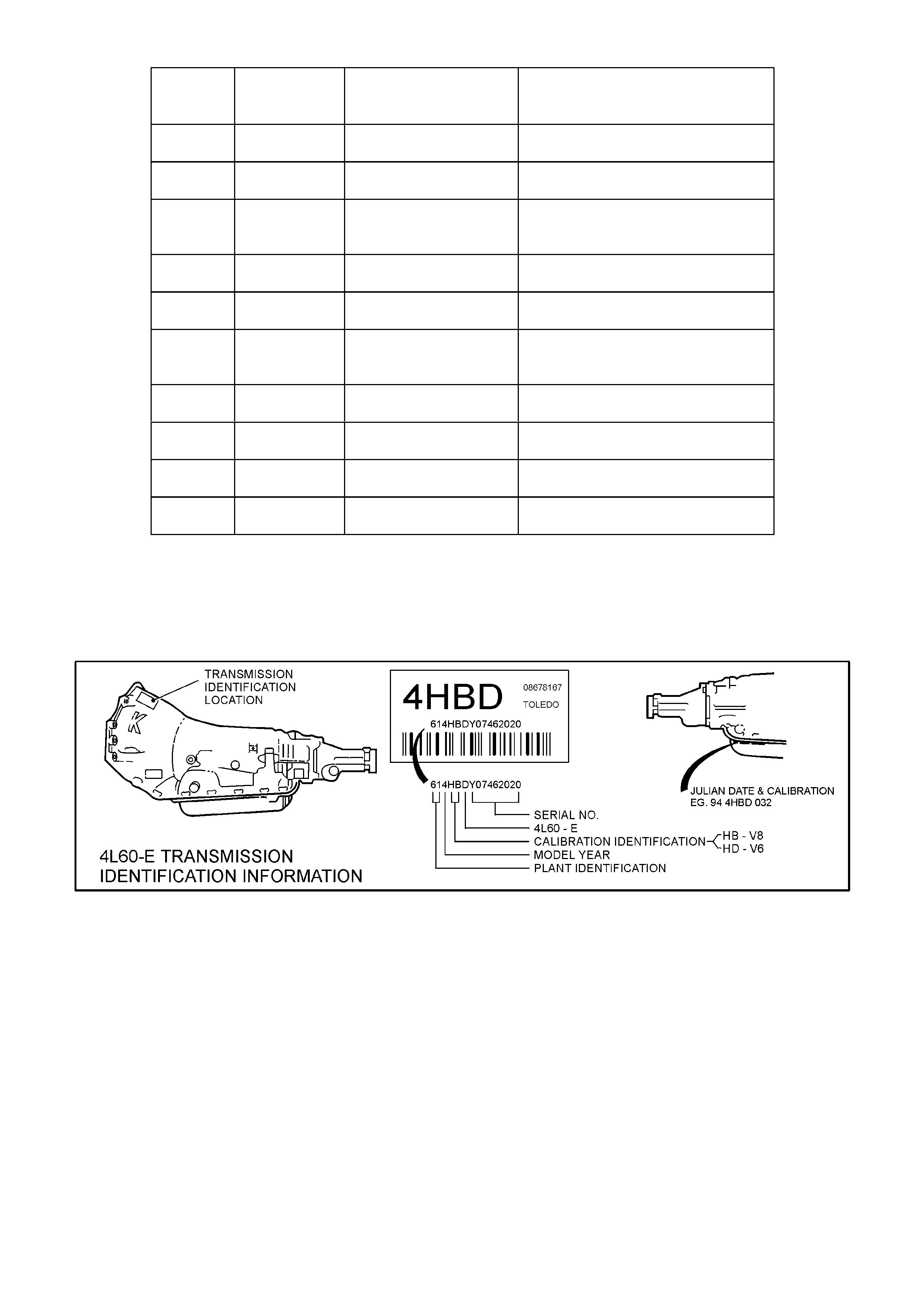
NOTE:
As vehicles can be built out of sequence, the vehicle Production Serial Number breakpoints in the above table
should be used as a guide only. Transmission model type should be confirmed from the transmission ID number,
refer to Figure 1, prior to ordering an SRTA transmission.
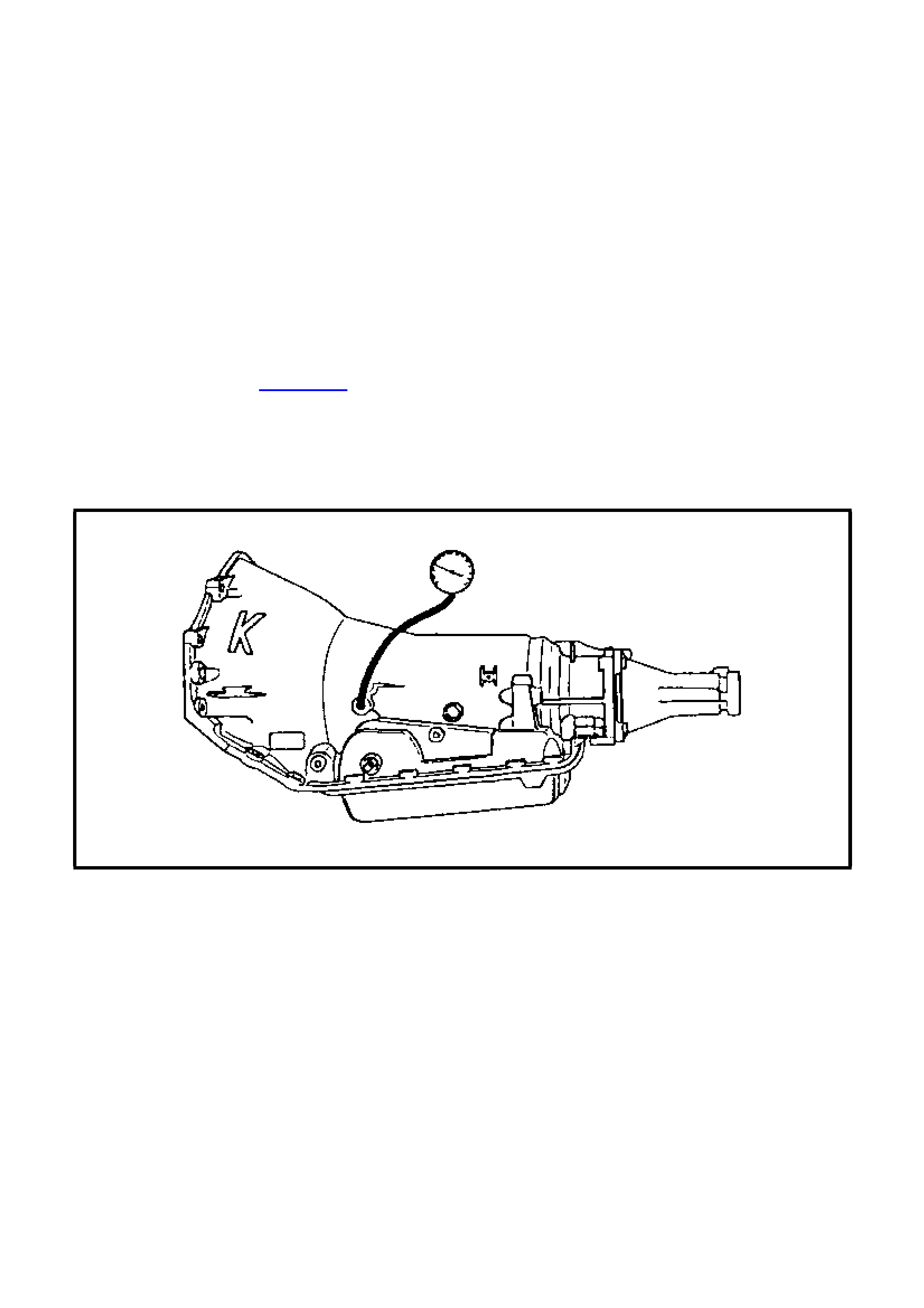
Figure 1 - Hydra-Matic 4L60-E Transmission Identification Information

DISTRIBUTION
SRTA Model transmissions can be ordered from your local SRTA Distributor listed below:
STATE DISTRIBUTOR ADDRESS CONTACT
Qld EAGERS RETAIL PTY LTD 95 Breakfast Creek Road,
Newstead, QLD 4006 Bill McElroy
PH: 07 3364 1124
FAX:07 3364 1044
Vic GM TRANSMISSION
REMANUFACTURING 70 Raglan St., Preston,
Vic. 3072 Mario Males
PH.: 03 9480 0988
FAX : 03 9480 2688
TAS MOTORS HOBART Collins St.
Hobart, TAS 7000 Tony Reardon or Barry Adcock
PH: 03 6220 1255
FAX: 03 6234 4732
SA MOTOR TRADERS 64 Grand Junction Rd
Kilburn, SA 5084 Ian Laughton or Lou Zauch
PH: 08 8349 4141
FAX: 08 8260 2447
NSW BOYDED INDUSTRIES 60 Hampstead Rd
Auburn, NSW 2144 Robert Mizzi
PH: 02 9648 3300
FAX: 02 9648 4534
NSW SUTTONS PARTS 22 Carter St
Lidcombe, NSW 2141 John Sherar
PH: 02 9648 3688
FAX: 02 9647 1483
WA COVENTRY’S 253 Walter Rd
Morley, WA 6062 Charlie Pintabona
PH: 08 9276 0111
FAX: 08 9276 1877
NT KERRY HOLDEN 21-25 Stuart Highway
Darwin, NT 0820 Dale Middleton
PH: 08 8980 8059
FAX: 08 8980 8051
RETURN OF FAILED TRANSMISSION (CORE) ASSEMBLY
Refer to the Core Exchange Return Procedure for the instructions that must be followed when returning the
failed transmission (core) to the Distributor.
The Dealer must complete the Transmission Report Form and the SRTA Transmission Product Feedback
Form supplied with the SRTA transmission.
Metropolitan Dealers: Your local SRTA Distributor will supply a pickup and delivery service to deliver SRTA
transm iss ion to your Dealer ship and pic k up the failed trans m ission f or retur n. The Dealer m ust notif y the Distributor
when a core unit is ready for pickup.
Country Dealers: SRTA transmissions will be shipped to country Dealers via IPEC overnight road express. An
IPEC consignment note preprinted with the address of the Distributor will be supplied with the SRTA transmission
for return of the core to the Distributor as soon as possible.
Note:
The failed transmission (core) must be returned to your local Distributor within 14 days to avoid being charged
$2,800 replacem ent cost. If for any reason the SRTA trans miss ion cannot be used or the failed transmiss ion (core)
cannot be returned within 14 days, the Distributor must be notified to avoid being billed for the transmission core.
Refer to the Transmission Core Return Process.
DOCUMENTATION
The following three pages are copies of the documentation that will be supplied with each SRTA transmission
supplied. The Automatic Transmission SRTA Product Feedback Form and the Transmission Report Form
must be filled out completely to assist in root cause analysis. Preprinted IPEC consignment notes, used for the
return of the failed transmission, will be provided with each SRTA transmission shipped to country Dealers.
A defective material tag (GMH-906) is not required for SRTA transmission replacements.

OIL COOLER FLUSHING
W hen fitting an SRT A transm ission, it is mandator y to carry out a cooler flush and f low chec k as detailed in Gr oup
7B of the November 1995 Service Techline. The cooler flush and flow check procedure in Section 7C4 of the VR
Service Manual was revised in line with this Service T ec hline. Pleas e ensur e that all c opies of your Service Manuals
have been updated accordingly, with “Revised, November 1995” printed at the bottom of page 7C4-24.
Failure to perf orm this cooler flush and f low check procedure m ay result in a repeat of transmis sion failure. Please
ensure your Dealership performs this mandatory procedure.
WARRANTY CLAIM DATA
The cost of removing and replacing the SRTA transmission must be claimed using the following special labour
operation number. The time allowed for this labour operation has been increased buy 0.4 hour to allow for
mandatory cooler flush and flow check procedure.
Description: Remove transmission and fit SRTA unit.
Labour Operation Number: K000225
Standard Time: 3.0 hours
Vendor Handling Allowance: 0.5 hour
SRTA - TRANSMISSION FREIGHT CHARGES
There have been is olated reports of Dealers being char ged freight cos ts for s hipping SRTA cor e units bac k to their
SRTA dist ributor, refer to DL 22/96. The following inf ormation is provided to ensure that all f reight cos ts as sociated
with the program are charged correctly.
Metropolitan Dealers: The SRTA Distributors provide a pickup and delivery service to all metropolitan dealers.
Holden will not accept freight charges for the pickup or delivery of SRTA transmission within the metropolitan area.
Country Dealers: Distributors will be supplied preprinted IPEC consignment notes with the charges payable by
third party section completed. These consignment notes have been delayed due to printing errors. In the interim,
when returning the core transm is sion to your distributor, include the f ollowing details in the charges payable by third
party section of the consignment note.
(Charges payable by third party)
Holden
Accounts Payable
Box 4375 GPO
Melbourne, 3001
Account Number 1501-7341

VT SERVICE REPLACEMENT TRANSMISSION ASSEMBLY (SRTA) PROGRAM UPDATE
DL 66/97
November 11, 1997
Effective immediately, new transmissions for warranty replacement on vehicles with less than 5000 km travelled
and covered by new car warranty, must be procured from SRTA Distributors.
Previously, these transmissions were procured from HSPO (and non-SRTA Distributors).
These transmissions are supplied on an FOC (Free Of Change) basis, and old units must be returned to SRTA
Distributors under the sam e procedur e as all other SRT A transm issions. For details of existing pr ocedures, ref er to
dealer letters DL 22/96, DL 45/96 and DL 5/97.
New transmissions for warranty repairs must not be procured from HSPO (or a non-SRTA Distributor). However,
for any vehicle not covered by new car warranty which requires a tr ansmission, a tr ansmiss ion m ust be purchased
from HSPO.
SRTA - MODEL INFORMATION
The following table lists the new transmissions now stocked by SRTA Distributors:
Year Model ID SRTA Part No. Description & Usage
1997 7HBD 24207572 VS 5.0L floor shift
7HCD 24207574 VS 3.8L column shift
7HDD 24207571 VS 3.8L floor shift
7HLD 24207575 VS 3.8L S/C floor shift
7HSD 24207573 VS 5.7L floor shift
1998 8HBD 24210662 VS & VT 5.0L floor shift
8HCD 24210663 VS 3.8L column shift
8HDD 24210664 VS 3.8L floor shift
8HFD 24210665 VT 3.8L floor shift
8HJD 24210667 VT 5.0L (195Kw, HSV) floor shift
8HLD 24210668 VS 3.8L S/C floor shift
8HND 24210669 VT 3.8L S/C floor shift
8HSD 24210670 VT 5.7L floor shift
1999 9HBD 24212817 VS & VT 5.0L floor shift
9HCD 24212812 VS 3.8L column shift
9HDD 24212813 VS 3.8L floor shift
9HFD 24212814 WH & VT 3.8L floor shift
9HJD 24212818 VS 5.0L (195Kw, HSV) floor shift
9HLD 24212815 VS 3.8L S/C floor shift
9HND 24212816 WH & VT 3.8L S/C floor shift
9HPD 24212821 WH & VT 5.7L (LS1) floor shift
9HSD 24212819 WH & VT 5.7L (L98) floor shift
2000 0HBD 24216091 VS & VT 5.0L floor shift
0HCD 24216092 VS 3.8L column shift
0HDD 24216093 VS 3.8L floor shift
0HFD 24216094 WH & VT 3.8L floor shift
0HJD 24216095 VS 5.0L (195Kw, HSV) floor shift
0HND 24216096 WH & VT 3.8L S/C floor shift
0HPD 24216097 WH & VT 5.7L (LS1) floor shift

DISTRIBUTION
The transmissions noted in the table above can be ordered from your local SRTA Distributor. An updated listing of
distributors is provided in the table below:
STATE DISTRIBUTOR ADDRESS CONTACT
Qld EAGERS RETAIL PTY LTD 95 Breakfast Creek Road,
Newstead, QLD 4006 Bill McElroy
PH: 07 3364 1124
FAX:07 3364 1044
Vic GM TRANSMISSION
REMANUFACTURING 70 Raglan St., Preston,
Vic. 3072 Mario Males
PH.: 03 9480 0988
FAX : 03 9480 2688
TAS MOTORS HOBART Collins St.
Hobart, TAS 7000 Tony Reardon or Barry Adcock
PH: 03 6220 1255
FAX: 03 6234 4732
SA MOTOR TRADERS 64 Grand Junction Rd
Kilburn, SA 5084 Ian Laughton or Lou Zauch
PH: 08 8349 4141
FAX: 08 8260 2447
NSW BOYDED INDUSTRIES 60 Hampstead Rd
Auburn, NSW 2144 Robert Mizzi
PH: 02 9648 3300
FAX: 02 9648 4534
NSW SUTTONS PARTS 22 Carter St
Lidcombe, NSW 2141 John Sherar
PH: 02 9648 3688
FAX: 02 9647 1483
WA COVENTRY’S 253 Walter Rd
Morley, WA 6062 Charlie Pintabona
PH: 08 9276 0111
FAX: 08 9276 1877
NT KERRY HOLDEN 21-25 Stuart Highway
Darwin, NT 0820 Dale Middleton
PH: 08 8980 8059
FAX: 08 8980 8051
Important:
Transmissions purchased from HSPO (or a non-SRT A Distributor) prior to the issue of this letter must be r eturned
when requested via the REPAC Report.
W hen transm issions are supplied on this FOC basis, old units must be returned to SRTA Distributors as per usual
SRTA procedures.
Dealers must assume responsibility for the completion of thorough and accurate diagnosis of fluid leaks prior to
commencing any rectification work or removing the transmission.
As in the past, dealerships are required to f lush and flow check the vehicles automatic transm ission cooling circuit
when changing a transmission. For details of this procedure for VT vehicles, refer to Section 7C4,
2.4 TRANSMISSION COOLER REVERSE FLUSH AND FLOW RATE CHECK, in the VT Series Service
Information CD.

SRTA - CORE RETURN PROCEDURE AND PROCESS CHART
AUTOMATIC TRANSMISSION - 24208340RW
CORE RETURN PROCEDURE
NOTE:
Instructions must be followed by your dealership when returning the core to the distributor.
1. Use care not to damage case.
2. Drain as much oil from the core as possible.
3. Remove all plastic shipping plugs from SRTA and install in core.
4. Install SRTA following the correct service procedures, refer Section 7C4, TRANSMISSION ASSEMBLY -
REINSTALL.
IMPORTANT:
Before installing Automatic Transmission (SRTA), oil cooler(s) and lines must be thoroughly flushed and clean.
5. Contact Holden Technical Assistance if you need diagnostic assistance.
6. Packet (plastic envelope) received with SRTA contains the following for:
VEHICLE OWNER:
Automatic Transmission/Transaxle Assembly (SRTA) Limited Warranty.
TECHNICIAN:
Product Feedback Form (Two-copy)
Must fill out Product Feedback Form completely.
Attach white copy of Product Feedback Form and a copy of the Repair Order inside the plastic envelope
supplied with the SRTA unit.
Place in plastic envelope received with SRTA.
Attach plastic envelope to bellhousing of Core Return.
Attach yellow copy of Product Feedback Form to original Repair Order and return to Service Manager.
SERVICE MANAGER:
Retain for your records yellow copy of Product Feedback Form and original Repair Order.
7. Carefully repack core in shipping container.
IMPORTANT:
Return core as soon as possible to your local distributor.
Core must be returned within 14 days.
If core cannot be returned within 14 days, contact you distributor immediately.
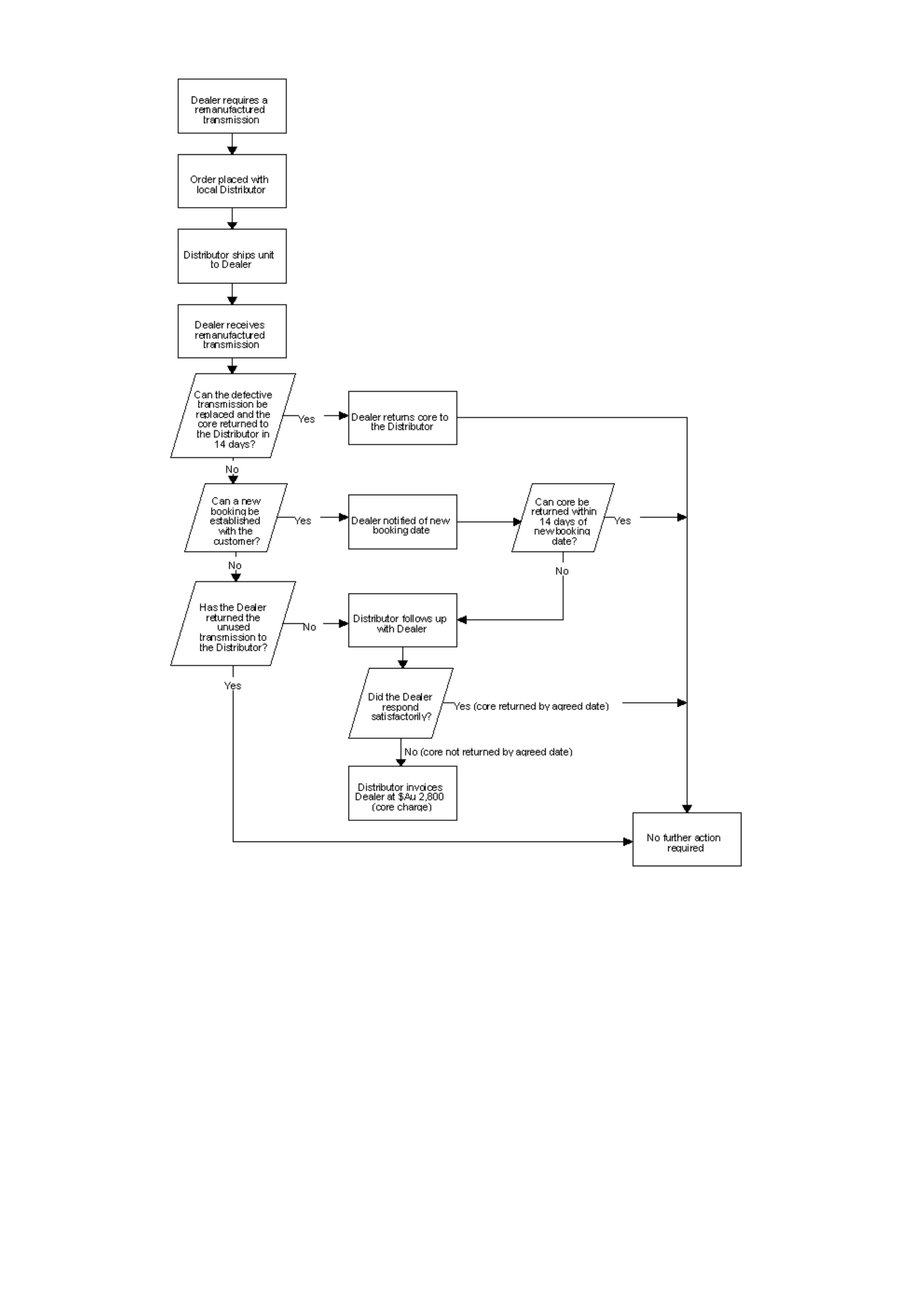
TRANSMISSION CORE RETURN PROCESS

SRTA - TRANSMISSION ORDER FORM (FORM F)
SRTA TRANSMISSION ORDER FORM
Use only black pen
DISTRIBUTOR:
DATE OF ORDER:
PART NUMBER REQUIRED:
(7 or 8 digit SRTA part number)
MODEL TYPE:
(4 digit Model eg. 6HDD)
VEHICLE ISO VIN NO:
(17 CHARACTERS)
ODOMETER READING:
VEHICLE WARRANTY START DATE:
SHIP TO:
DEALER NAME:
DEALER CODE:
CONTACT NAME:
TELEPHONE NUMBER:
ADDRESS:
Distribution Use Only:
Date shipped:
FORM ( F): ALL DETAILS TO BE FULLY CO MPLETED ON FORM.
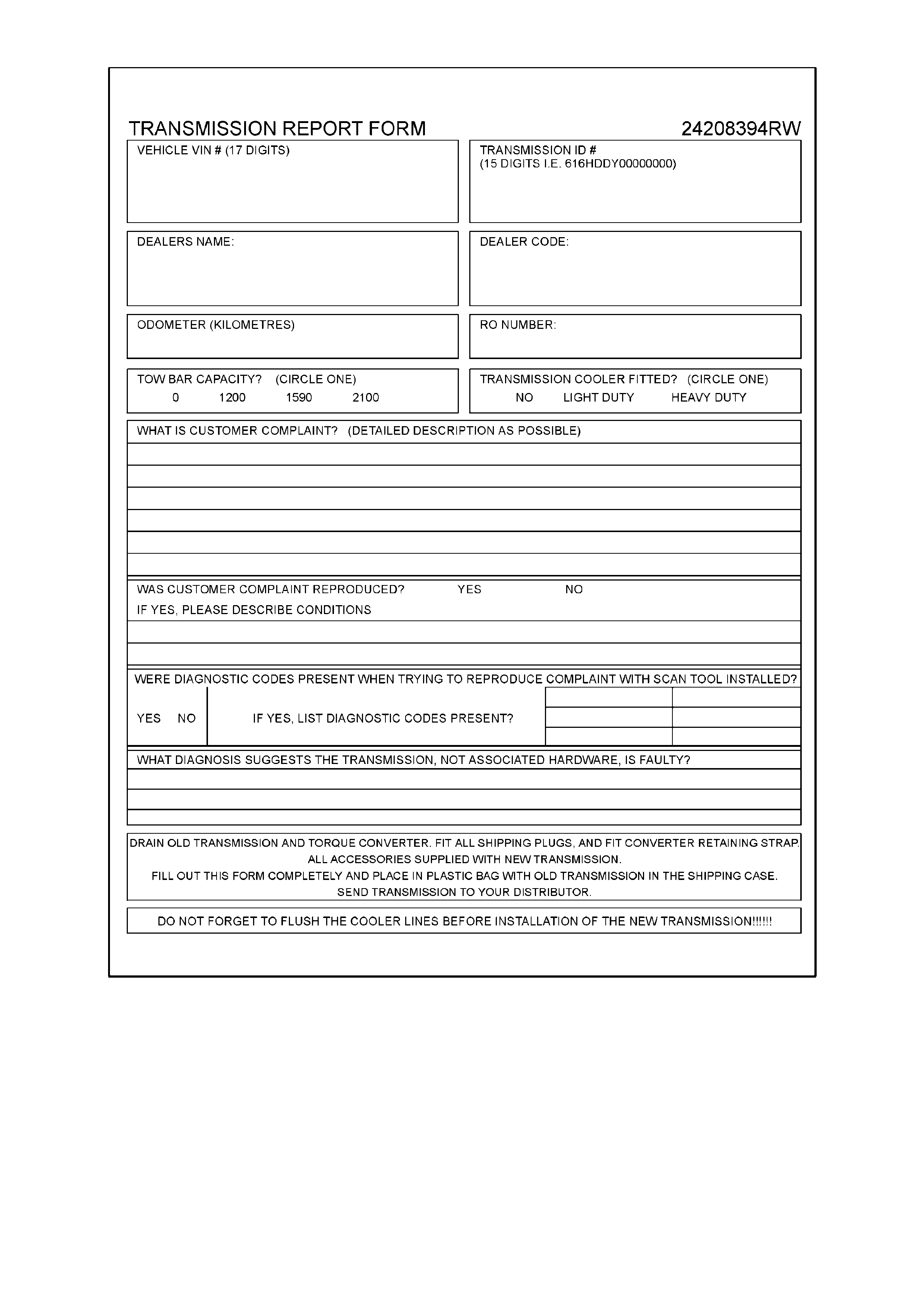
SRTA - TRANSMISSION REPORT FORM (24208394RW)
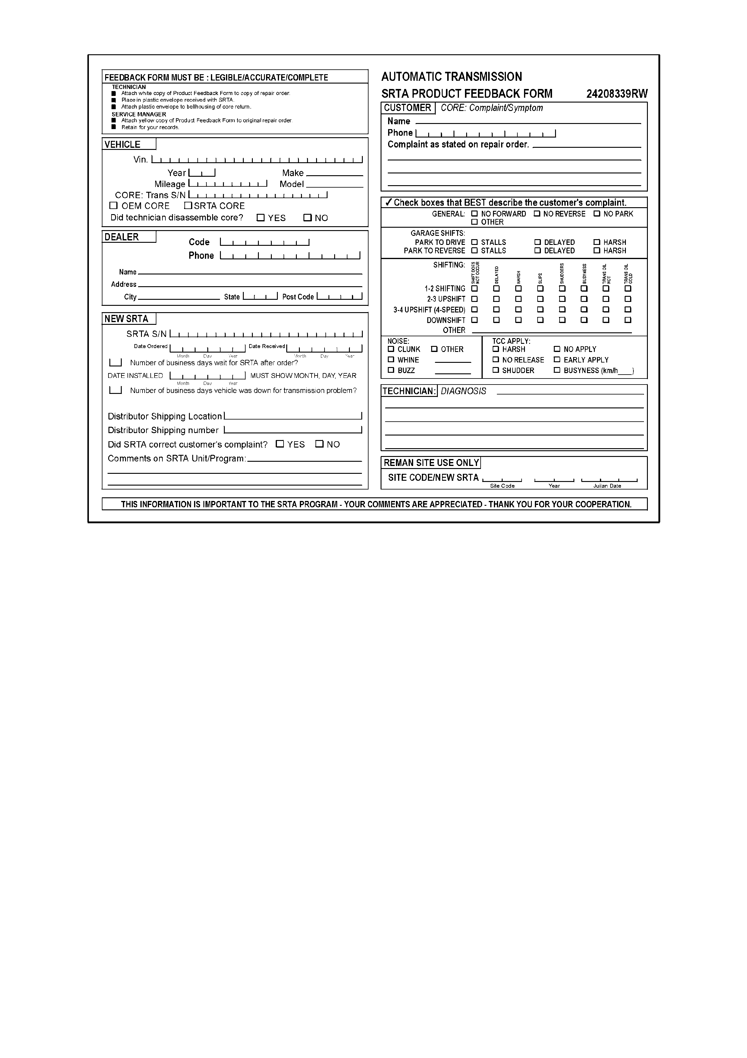
SRTA - PRODUCT FEEDBACK FORM (24208339RW)
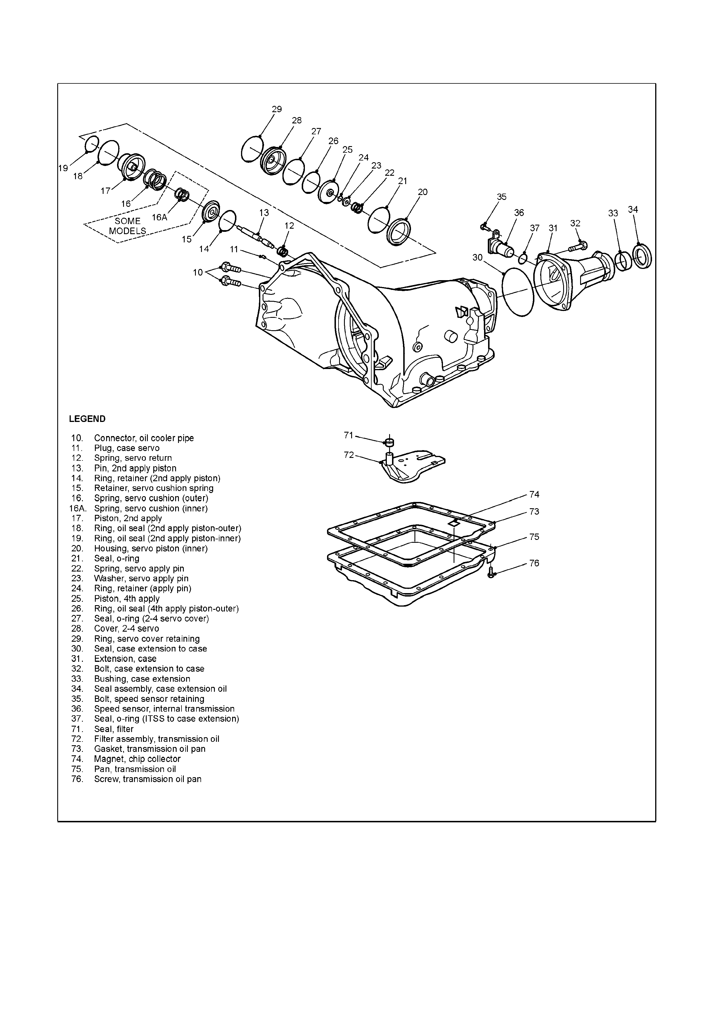
TRANSMIS S ION PARTS DIAGRAM AND TEST PROCEDURES
TRANSMISSION PARTS DIAGRAM
LINE PRESSURE CHECK PROCEDURE
Line pressures are calibrated for two sets of gear ranges, Drive-Park-Neutral and Reverse. This allows the
transmission line pressure to be appropriate for different pressure needs in different gear ranges:
Gear Range Line Pressure Range
Drive, Park or Neutral 55-189 psi
Reverse 64-324 psi
Before performing a line pressure check, verify that the pressure control solenoid is receiving the correct electrical
signal from the PCM:
1. Install the appropriate scan tool for the vehicle model.
2. Start the engine and set parking brake.
3. Check for a stored pressure control solenoid diagnostic trouble code, and other diagnostic trouble codes.
4. Repair vehicle if necessary :
Inspect
Fluid level (refer to Section 7C4 of this Service Information CD.)
Manual linkage
Install or connect
Appropriate scan tool for the vehicle model
Oil pressure gauge at line pressure tap
Oil Pressure Gauge Line Pressure Tap
5. Put gear selector in Park and check that the parking brake is still set.
6. Start engine and allow it to warn up at idle.
7. Access the ‘PCS Control’ test on the scan tool.
8. Increase DESIRED PCS in 0.1 Amp increments and read the corresponding line pressure on the pressure
gauge. Allow pressure to stabilise for 5 seconds after each current change.
9. Compare data to the Drive-Park-Neutral line pressure chart below.
NOTICE:
Total test running time should not exceed 2 minutes, or transmission damage could occur.
CAUTION:
Brakes must be applied at all times to prevent unexpected vehicle motion.
If pressure readings differ greatly from the line pressure chart, refer to the Diagnosis Charts contained in this
Service Information CD, refer Section 6C1 - V6 ENGINE or Section 6C2 - V8 ENGINE.
The s can tool is only available to control the press ure c ontrol solenoid in Par k and Neutr al with the vehicle stopped.
This protects the clutches from extremely high or low pressures in Drive or Reverse ranges.
DRIVE-PARK-NEUTRAL LINE PRESSURE CHART
Pressure Control Solenoid
Current (Amp) Line Pressure (psi)
0.02 170 – 190
0.10 165 – 185
0.20 160 – 180
0.30 155 – 175
0.40 148 – 168
0.50 140 – 160
0.60 130 – 145
0.70 110 – 130
0.80 90 – 115
0.90 65 – 90
0.98 55 – 65
Pressures at 1500 rpm and 66°C (150°F). Line pressure drops as temperature increases.
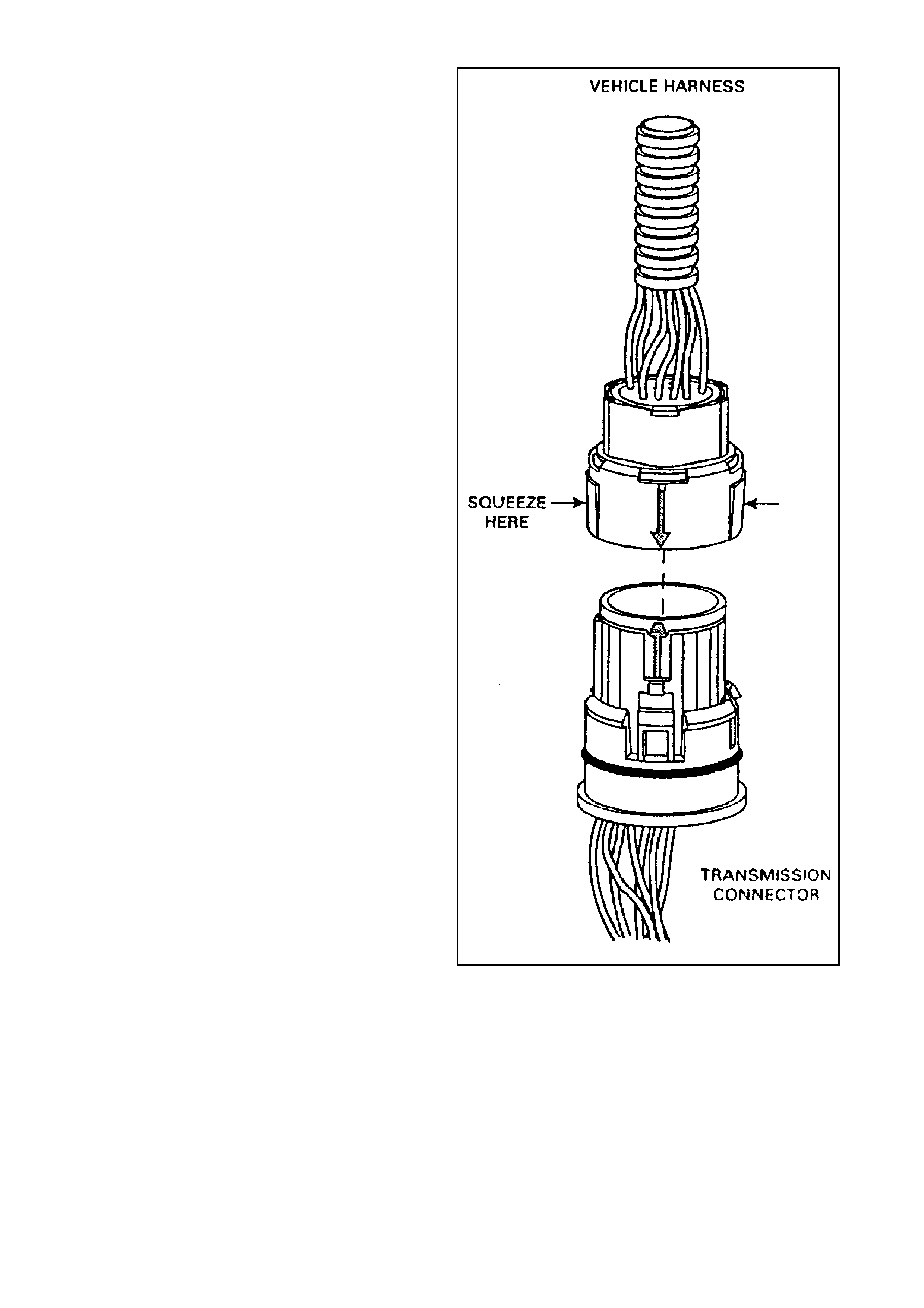
TRANSMISSION ELECTRICAL CONNECTOR CHECK PROCEDURE
The transmission electrical connector is a very
important part of the transmission operating
system. Any interference with the electrical
connection can cause the transmission to set
Diagnostic Trouble Codes (DTCs) and/or affect
proper operation.
The following items can affect the electrical
connection:
Bent pins in the connector f r om rough handling
during connection and disconnection.
Wires backing away from the pins or coming
uncrimped (in either internal or external wiring
harness).
Dirt contamination entering the connector
when disconnected.
Pins in the internal wiring connector backing
out of the connector or pushed out during
reconnection.
Excessive transmission fluid leaking into the
connector, wicking up into the external wiring
harness and degrading the wire insulation.
Water/moisture intrusion in the connector.
Low pin retention in the external connector
from excessive connection and disconnection
of the wiring connector assembly.
Pin corrosion from contamination.
Broken/cracked connector assembly.
Points to remember when working with the
transmission wiring connector assembly:
To remove the connector, squeeze the two
tabs towards each other and pull straight up
(refer to the illustration).
Carefully limit twisting or wiggling the
connector during removal. Bent pins can
occur.
DO NOT pry the connector off with a
screwdriver or other tool.
To install the external wiring connector, first
orient the pins by lining up the arrows on each
half of the connector. Push the connector
straight down into the transmission without
twisting or angling the mating parts.
The connector should click into place with a
positive feel and/or noise.
Whenever the transmission external wiring
connector is disconnected from the internal
harness and the engine is operating DT Cs will
set. Clear these DTCs after reconnecting the
external connector.
Transmission Electrical Connector
HYDRA-MATIC 4L60-E TRANSMISSION FUNCTION TEST