
2
20
00
03
3
S
SE
ER
RV
VI
IC
CE
E
T
TE
EC
CH
HL
LI
IN
NE
ES
S
© 2006 GM Holden LTD. A.B.N. 84 006 893 232
Service Department
A “HOLDEN” Product.
BRISBANE SYDNEY MELBOURNE ADELAIDE PERTH
For the latest and/or any missing Techline bulletins,
please refer to Holden Lionheart
HOLDEN SERVICE TECHLINE_____________________________________________________ __________JANUARY, 2003
5
Glove Box Light Stays on with Glove Box
Lid Closed
VY
(GROUP 12) TL416-0301
PROBLEM DESCRIPTION
There have been several reports of vehicles in which
the glove box light remains on after the glove box lid
is closed. The customer’s complaint may be that
they are able to see the light on in the glove box at
night while driving.
These vehicles may be affected by a condition where
the wiring harness behind the glove box was
incorrectly installed and subsequently touches the
right hand rear corner of the glove box. This may
cause the glove box to distort and the glove box light
switch to turn on.
This condition will not cause the vehicle battery to be
discharged as the glove box light circuit is controlled
via the BCM battery saver function. The light is
switched off at the time period programmed into the
BCM (default is 65 minutes) or 10 seconds after the
vehicle is locked.
PRODUCTION RECTIFICATION
Vehicles were rectified in production by relocating the
wiring harness and fitting an extra tie strap.
ISOVIN: Build Date:
6G1YL52B53L945885 25/11/02
SERVICE RECTIFICATION
Summary: On complaint vehicles, reposition
glovebox wiring harness and increase length of
glovebox switch plunger.
Procedure.
1. Remove the glove box as per the procedure in PV
SIP VY / Internal Fittings / Section 1A3 –
Instrument Panel & Console / 3. Service
Operations - Instrument Panel / 3.2 Instrument
Panel Compartment Assembly / Remove.
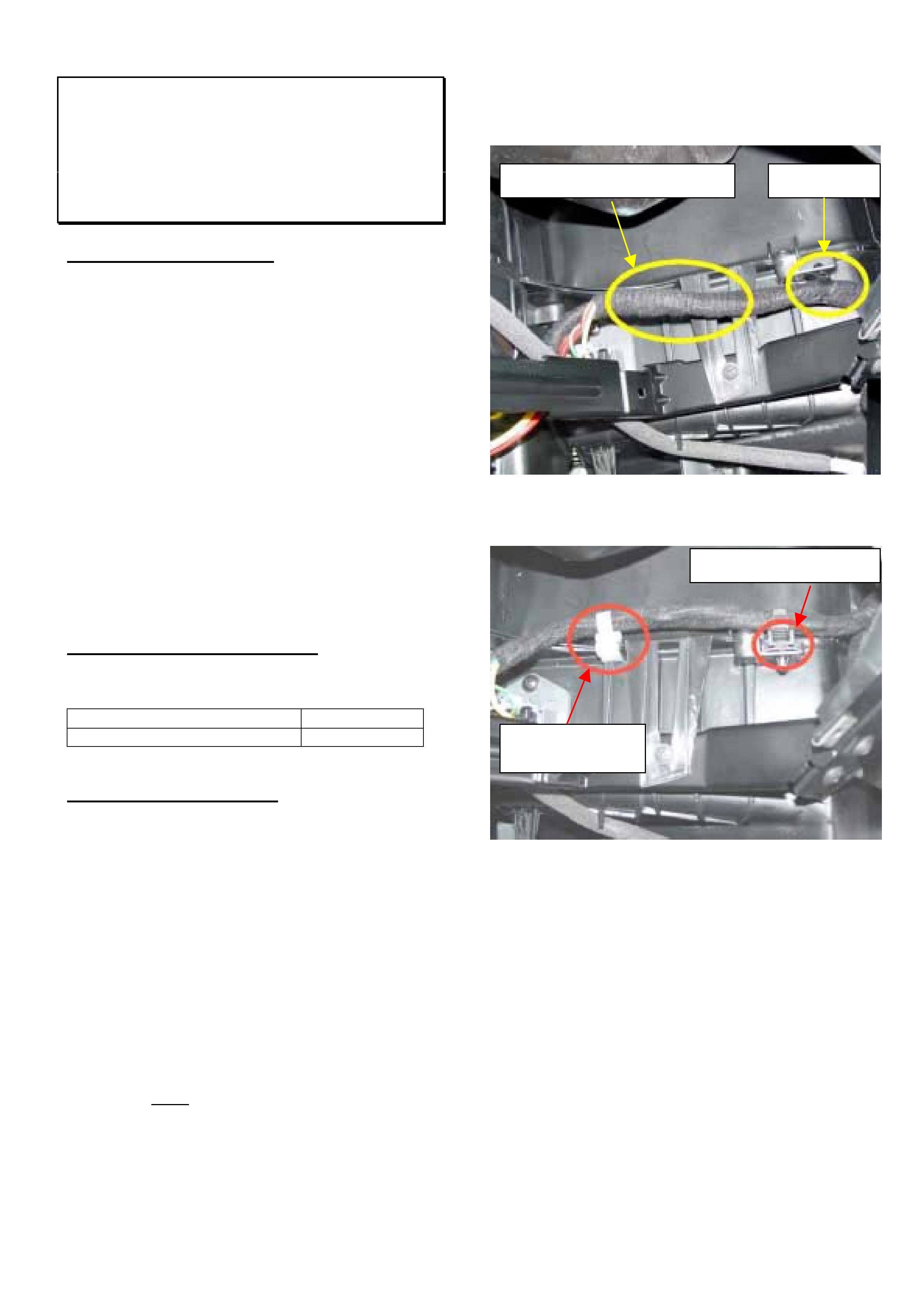
2. Locate the heater fan wiring harness on the right
hand side rear of the glove box opening beside
the HVAC case. Refer Figure 1.
3. Remove, invert, and reinstall the original retaining
tie strap (A) in the HVAC case as shown in
Figure 2.
4. Add a new tie strap (part of kit 92146705) above
the rib in the HVAC case. Refer Figure 2.
Figure 1. Original location of harness and tie strap”A”.
Figure 2. Revised location of harness and tie straps
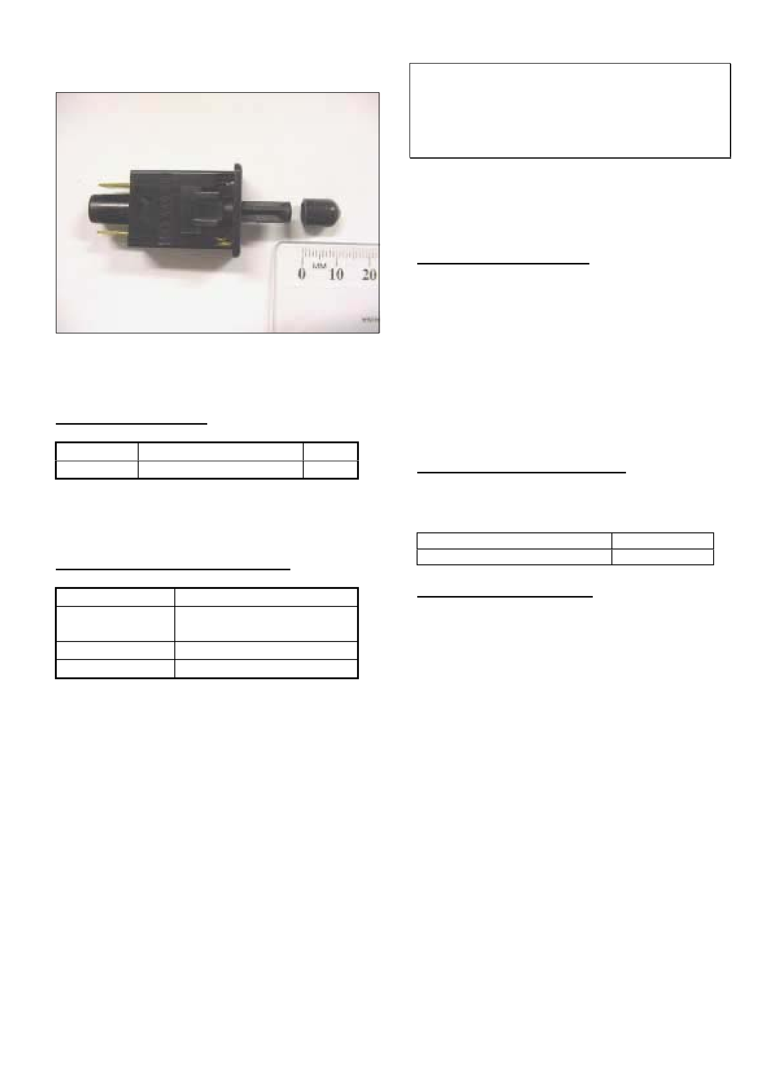
5. Remove the glove box switch from the glove box
housing.
6. Trim the rubber blanking plug (which is part of the
service kit) to an over all length of 8 - 10 mm.
Refer Figure 3.
7. Place the rubber-blanking plug over the switch
plunger (it may be necessary to hold the switch
plunger with pointy nose pliers to ensure the
blanking plug is pushed all the way on).
8. Refit the switch.
Area of contact with glove box Tie Strap A
Tie Strap A, “Inverted”
New Tie Strap
(Above the casting rib)
HOLDEN SERVICE TECHLINE_____________________________________________________ __________JANUARY, 2003
6
9. Check for correct operation of glovebox light.
Figure 3. Trim rubber blanking plug length to 8-10mm
prior to installing onto plunger.
PARTS INFORMATION
Part No.: Description: Qty:
92146705 Glovebox light kit 1
The Kit consists of a tie strap and rubber blanking
plug.
WARRANTY CLAIM INFORMATION
Description Fit glove box light kit
Labour Op.
No.
N000414
Time 0.4
Failure Code 80
Horn Intermittently Stays On
VY
(GROUP 12) TL420-0301
This Techline was instigated by TAS calls and PIRs.
Thanks in particular to James Brown of Canobolas
Holden for submitting the first PIR which detailed the
exact cause of the problem.
PROBLEM DESCRIPTION
Some customers may complain that their vehicle’s
horn intermittently sounds on its own.
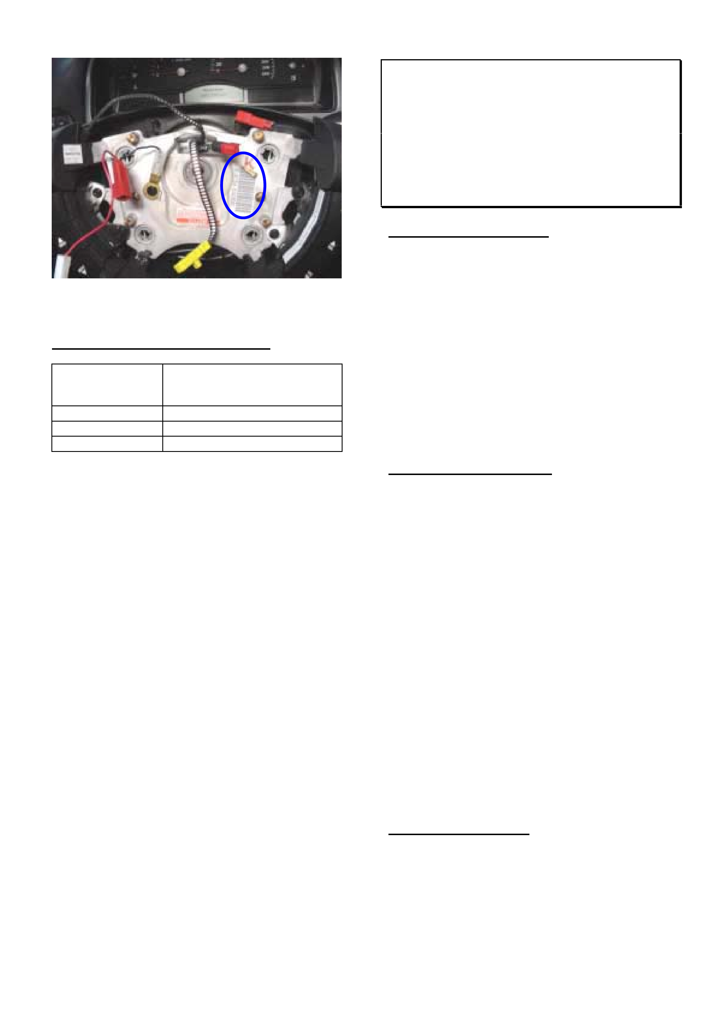
Investigation of these cases reveals that a metallic
backed barcode label fixed to the steering wheel
directly below the horn bar contact (which is located
on the underside of the airbag) may curl up and earth
the horn bar contact which causes the horn to sound.
This condition may be more common with increased
cabin temperatures.
PRODUCTION RECTIFICATION
Steering wheels with relocated barcode labels were
fitted to vehicles from:
ISOVIN: Build Date:
6G1YK43A23L9648463 30/1/03
SERVICE RECTIFICATION
1. Remove the air bag as per the procedure in PV
SIP VY / Electrical System / Section 12M
Occupant Protection System / 2. Service
Operations / 2.3 Steering Wheel Inflatable
Restraint Module Assembly.
2. Inspect the steering wheel hub for a label as
shown in Figure 1.
3. Remove the label highlighted in Figure 1.
4. Reinstall the air bag as per the SIP procedure.
HOLDEN SERVICE TECHLINE_____________________________________________________ __________JANUARY, 2003
7
Figure 1. Bar code label on steering wheel.
WARRANTY CLAIM INFORMATION
Description Airbag unit drivers SRS -
Remove and detach barcode
label from steering wheel.
Labour Op. No. M000187
Time 0.3 hr
Failure Code 62 Improper clearance
“ADVANCED SERVICE INFORMATION”
Ignition Key Jams In Off Position Or Is
Difficult To Turn from Off Position
TS Astra
(GROUP 9) TL421-0301
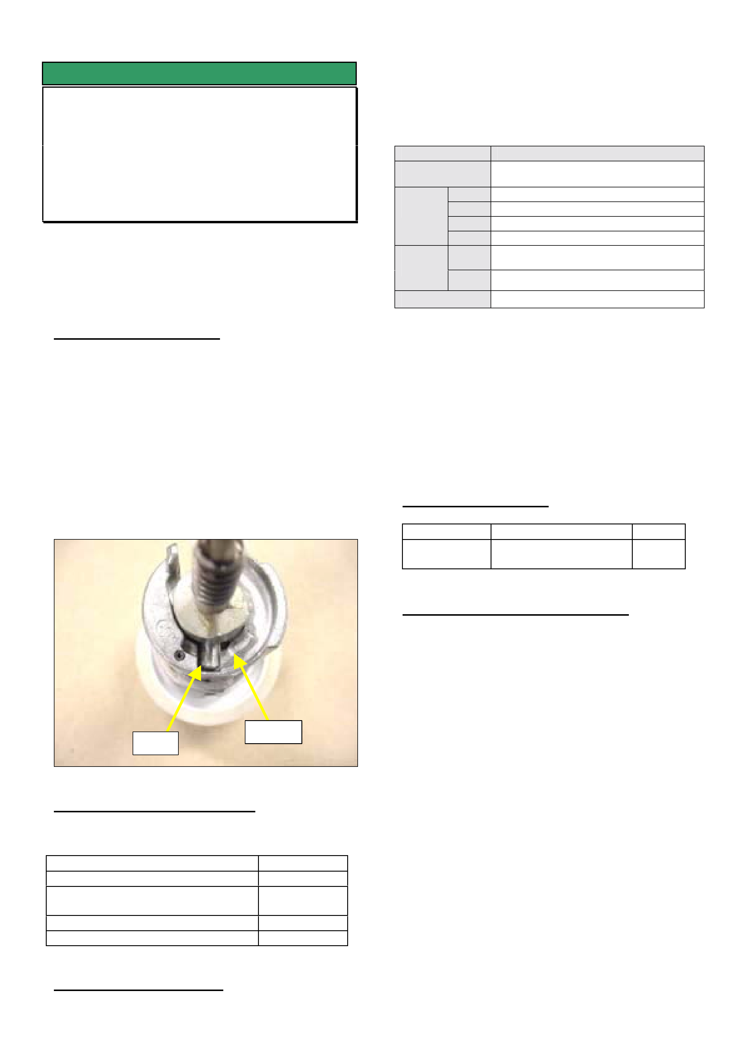
PROBLEM DESCRIPTION
In some vehicles the ignition key may jam in the
“OFF” position or be difficult to turn from the “OFF”
position.
This condition appears only to affect ignition
barrels/keys with “S” profile. It does not affect those
with “D” profile. For profile recognition refer to Part
Finder TS Catalogue, section 06-250A.
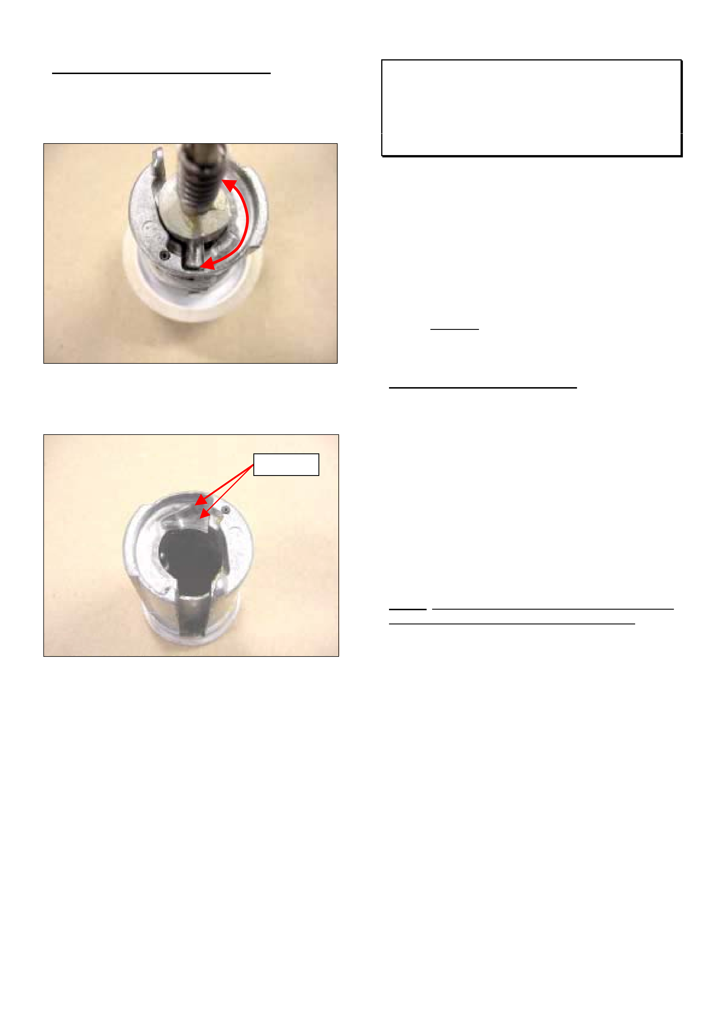
The cause of this condition appears to be due to the
hard pin causing excessive wear on the ramp section
of the barrel. Refer Figure 1. Production rectification
of this condition is in progress. Production
breakpoints and service fix information will be
released when available.
SERVICE RECTIFICATION
Until advised otherwise, complaint vehicles should be
fitted with a new ignition barrel. However, In the
event that new parts are unavailable, the following
procedure can be used to rework existing parts to
eliminate binding.
Rework Procedure For Existing Parts.
1. Disassemble pin and spring from outer barrel
(take care because spring may "eject" pin away).
2. Clean pin wear area with rag - see Figure 1.
3. Inspect outer barrel housing for wear caused by
pin.
4. If pin has excessively worn the barrel, de-burr the
cast barrel material with a sharp blade to allow
smooth pin travel on surface of barrel. Refer
Figure 2.
5. Lubricate with powdered graphite only.
PARTS INFORMATION
Refer to Partfinder for replacement ignition barrel part
numbers.
HOLDEN SERVICE TECHLINE_____________________________________________________ __________JANUARY, 2003
8
WARRANTY CLAIM INFORMATION
Use Labour Times information in Warranty
Information section of current PV SIP CD
Figure 1. Pin wear area on barrel
Figure 2. De-burring pin wear area.
Rocker Arm Bolt Sealing
HSV Gen III V8 – 300Kw Version
(GROUP 6A) TL419-0301
In 300kW Gen III V8 engines, the rocker arm bolts
protrude into the inlet ports because additional
porting has been carried out.
Oil consumption, via oil migrating down the thread/s,
may be possible, if the rocker arm bolt threads are
not sealed.
To ensure this oil migration (and possible oil
consumption) does not occur, the threads are sealed
in production with a Teflon based thread sealant.
NOTE: Standard Gen III V8 engine rocker arm bolts
do NOT protrude into the ports and MUST NOT have
the threads sealed.
SERVICE REC0MMENDATION
Summary: Apply sealant to bolts whenever repairing
a 300kW Gen III V8 engine/cyl. head.
300Kw Engine rocker arm bolts must be sealed
whenever removed for any reason.
This sealing of rocker arm bolts should become a
standard operation whenever rebuilding a 300Kw
Gen III 300kW engine.
The sealant used is a Teflon based thread sealant,
Loctite No. "567", or equivalent, available from
Industrial suppliers such as BSC, CBC, Blackwoods,
etc.).
NOTE: DO NOT CARRY OUT THIS SEALING ON
Standard Gen III V8 engine rocker arm bolts – they
do NOT protrude into the ports and MUST NOT have
the threads sealed. Applying thread sealant to
standard engine rocker arm bolts may stop bolts from
seating correctly or achieving the correct retention
torque.
De-burr

HOLDEN SERVICE TECHLINE_____________________________________________________ __________JANUARY, 2003
9
Instrument Cluster DTC 8
(New Vehicles Only)
VY Ute without ABS / ETC
(GROUP 12 TL417-0301
DTC 8 (no serial data from ABS / ETC) has been
present on all new VY ute’s without ABS / ETC from
start of VY production.
This DTC will not cause any customer detectable
symptoms, and is only evident when DTC’s are
checked with Tech 2 or using the Instrument cluster
self diagnostic mode.
There is no production/service rectification proposed
therefore technicians should ignore this code.
HOLDEN SERVICE TECHLINE____________________________________________________________FEBRUARY, 2003
6
Stop / Tail Light Globe Failure
VX / WH / V2 / VY
(GROUP 12) TL395-0302
PROBLEM DESCRIPTION
Warranty data shows that there is an ongoing high
level of replacement of stop/tail light globes.
A large percentage of the globes returned to REPAC
are tested and found to have no fault.
SERVICE RECOMMENDATION
The following procedure is recommended when
rectifying stop/tail light globe not functioning.
Visually inspect the globe filament or use an Ohm
meter to ensure that you have a circuit through the
globe.
• If the globe is blown it should be replaced with a
long life globe from HSPO, ensuring it has a blue
dot at the base, which confirms that it is long life.
• If the globe is not blown check the stop/tail
globe socket contacts and grommet to ensure that
it is not trapping the wire and preventing good
socket to globe contact. This condition can be
rectified by pushing more wire through the
grommet to relieve tension.
PARTS INFORMATION
Part No.: Description: Qty:
92080588 Long life stop/tail light
globe
1
Power Steering Reservoir Retention
VY with V6
(GROUP 9) TL402-0302
PROBLEM DESCRIPTION
On some vehicles the power steering reservoir may
not be positively retained by the retaining clip on the
fan shroud.
PRODUCTION RECTIFICATION
Vehicles have been checked for correct retention of
power steering reservoir from:
ISOVIN: Build Date:
6G1YK54A63L943179 14/11/02
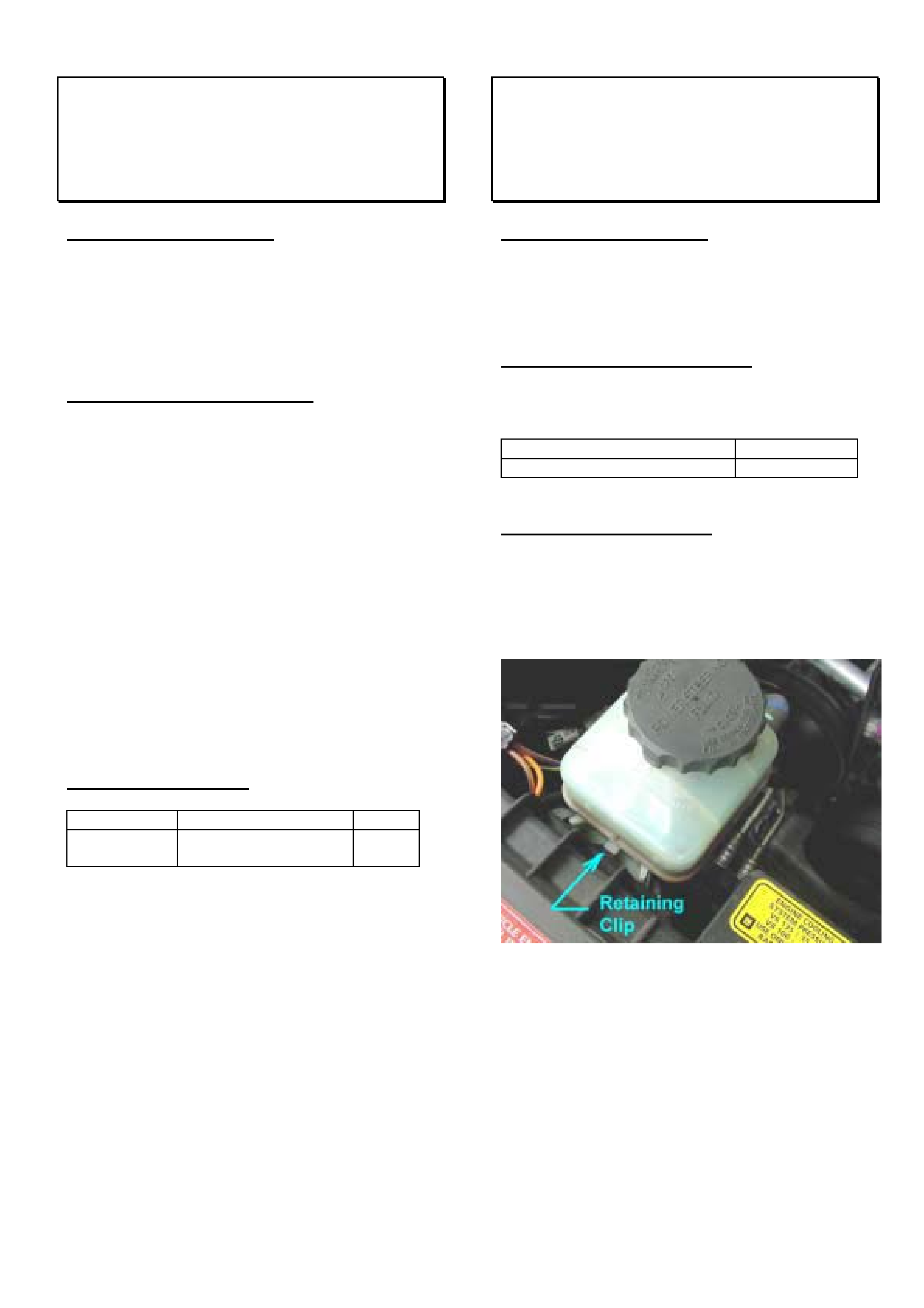
SERVICE RECTIFICATION
Vehicles found to have loose reservoirs should be re-
installed, taking special note that the retaining clip
(moulded as part of fan shroud) is correctly engaged
in position (see Figure 1 below) to ensure positive
retention of the reservoir.
Figure 1.
HOLDEN SERVICE TECHLINE____________________________________________________________FEBRUARY, 2003
7
Knock Or Thud Noise Under Heavy
Acceleration From Rest
VY Gen 3 & M/T
(GROUP 4) TL435-0302
PROBLEM DESCRIPTION
Under hard acceleration from a standing start, some
vehicles may experience a loud knock/thud from the
rear underbody area.
Investigation shows that this condition can occur if
the rear crossmember to underbody insulators are
missing.
NOTE: Some vehicles within the following range may
have been built without these insulators.
From: 6G1YL54F63L949461 - 28 Nov 2002
To: 6G12X14F53L976377 - 12 Feb 2003
SERVICE RECTIFICATION
Summary: On complaint vehicles check if insulator is
missing. Install as required.
Procedure.
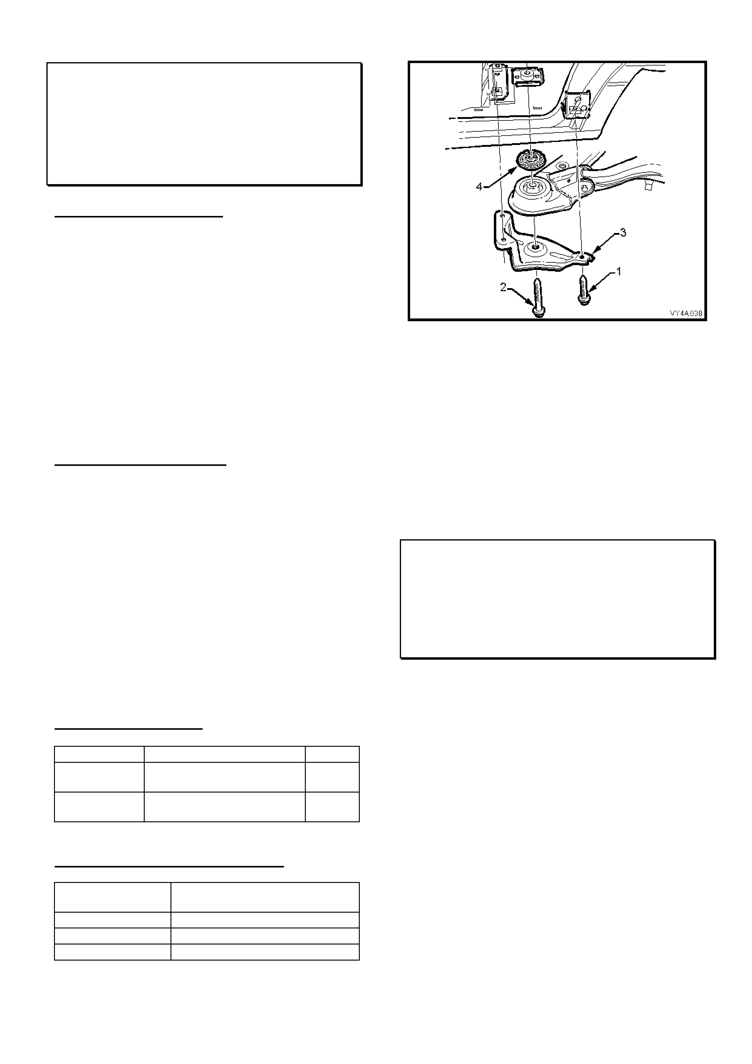
1. Raise car on hoist.
2. Inspect for presence of insulator (both sides).
Refer Figure 1.
3. Install new insulator if required. Refer PV SIP
procedure as follows:
Select - VY Series / Section 4A / 2.5 Rear Susp
crossmember front bush / On car replacement.
Note. New rear suspension front mounting to
underbody bolts will be required.
PARTS INFORMATION
Part No.: Description: Qty:
90447991 Insulator- Rear
Crossmember
2
92038482 Bolt – Rear susp. front
mounting to underbody
2
WARRANTY CLAIM INFORMATION
Description Install insulator - rear
crossmember both sides
Labour Op. No. F000185
Time 0.5 hr
Failure Code 29 missing
Figure 1. (Insulator = No. 4)
New TIS Option Available – “Default To
LPG On Startup”
VY & LPG, Sedan & Ute
(GROUP 6C) TL422-0302
The purpose of this techline is to inform Retailer
Service Departments of a new LPG calibration
available in TIS CD 39.0B which defaults to LPG on
startup.
This feature has been produced to meet the
requirements of those fleet operators who wish to
operate their vehicles on LPG for most of the time.
This calibration can be installed at customers
request. It should be pointed out to customers that
the requirement to keep petrol in the petrol tank as
detailed in the LPG Owners Handbook Supplement
still applies.
The part number for this calibration is 92160884 and
the display in TIS is;
LPG (Liquid Petroleum Gas) – Default LPG Starting.
HOLDEN SERVICE TECHLINE____________________________________________________________FEBRUARY, 2003
8
Engine Stall At Idle Or High Engine Idle
Speed
JR, JS, C20SEL, C22SEL
TR GSi X20XEV
(GROUP 6C) “REVISED” TL431-0302
This Techline supersedes the previous one in Issue 5,
June, 2002. It is revised by adding TR GSi with
X20XEV engine to the models affected . Note: For TR
GSi, a new engine calibration to suit the new IACV is
released on TIS CD 39.
PROBLEM DESCRIPTION
Some owners may complain of the following
symptoms:
With vehicle speed less than 3km/hr or vehicle
stationary, the engine idle is too high; e.g. 1000 RPM+,
and engine may later stall or the idle may remain high.
This is caused by a build-up of engine by-pass gases
and IACV solenoid shaft/bearing wear particles on the
IACV solenoid shaft, which causes the IACV to stick at
any point in its operating range. This will result in either
too high or too low IACV air entry to the throttle body
and engine.
When the IACV subsequently “unsticks” and returns to
normal operation, the result may be a stall or higher
than normal idle RPM. It is not possible to effectively
clean the IACV to correct this condition.
PRODUCTION RECTIFICATION
Revised Idle Air Control Valves (IACV’s) have been
fitted to all vehicles despatched from Port Of Entry
facilities commencing 24th Sep. 2001.
GENERAL MAINTENANCE NOTE
The need to carry out careful checks of all engine
compartment hoses at regular maintenance services is
stressed to all Technicians, to ensure continued,
efficient vehicle operation. This includes checking the
engine PCV and air intake hoses.
SERVICE RECTIFICATION
Summary: Fit revised IACV, flash program as required,
check/clean PCV port, check hoses.
On vehicles with the above symptoms perform
diagnosis to determine if the IACV is, in fact, the cause
of the problem. Refer to previous Techline item in
SIP/2001/Group 6C titled “Engine Stall Diagnosis - Non
IACV Related Causes”. After confirming that nothing
else is causing the stall, proceed to fit the latest
“diaphragm type” IACV using the following procedure.
1. Remove old IACV and install new diaphragm type
IACV and gasket as per procedures shown in TIS
CD.
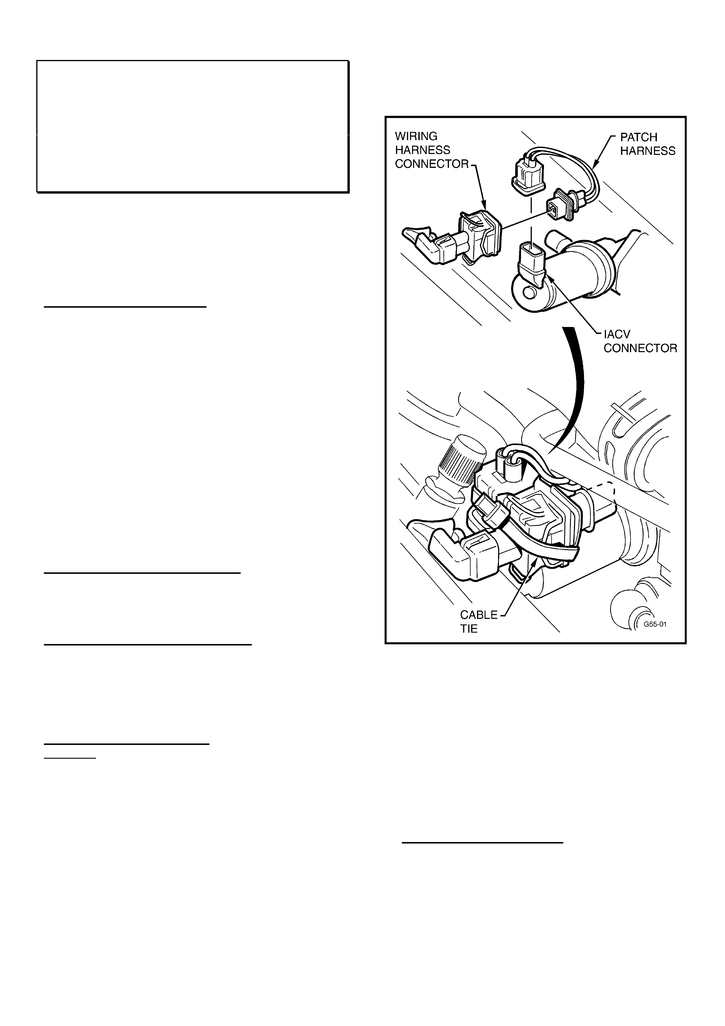
2. Fit the patch harness (refer Figure 1) – this is an
interface patch harness to connect the existing
vehicle wiring harness to the new IACV.
Figure 1.
3. Use a tie strap to firmly bind the wiring harness
connector to the IACV connector as shown in
Figure 1. Cut off any excess strap.
4. Use TIS 2000 CD version 39 or later (and latest
Tech 2 Software ) to flash program the “New IACV”
calibration into the vehicle via TIS Service
Programming System (SPS). Refer to Flash
Programming Details and Calibration Part
Numbers below.
Flash Programming Details:
Select the vehicle parameters that apply to the
vehicle being programmed.
For example: Holden; VECTRA-B; 2000; C22SEL
Engine,
HOLDEN SERVICE TECHLINE____________________________________________________________FEBRUARY, 2003
9
THEN, for “Type of Idle Air Control Valve” select
“New IACV (PN.: 92 065 903)”,
THEN, select the “Type of Transmission”.
When type of Trans. is selected, if you are prompted
for either “Short Y” or “Long Y” types of exhaust
system:
“Short Y” exhaust front engine pipe has a “Y” (2 into
1) joint directly below the front of the engine block;
“Long Y” exhausts have the Y joint further rearward
approximately in line with the sump plug.
NOTE. “Short Y” is used with F18 M/T. “Long Y” is
used with later F23 M/T introduced in JSII from
L482379 22/7/99.
Model: Old
Calibration
New
Calibration
JR & JS C20SEL 90569364.**** 92066071.2657
JS 1, C22SEL
(Short Y front
pipe)
92059405.**** 92066073.2658
JS 2, C22SEL
(Long Y front
pipe)
92085493.2659 92066074.2660
TR (Astra F) &
X20XEV
90519068.2616 93175683.2561
(**** = any Number )
After reprogramming is completed proceed as follows.
5. CHECK FOR AND REMOVE PREVIOUSLY SET
BASE IDLE AS PER FOLLOWING STEPS (a)
to (d).
Failure to remove any previously set base idle
could affect the operating characteristics of the
new IACV.
(a). With Tech 2 connected select the Data Display
screen, start the vehicle and allow it to come to
operating temperature (greater than 70 deg C
coolant and inlet air temp between 20 - 30 deg C)
with moderate to high underbonnet temperatures)
(b). With A/C OFF check "IACV steps" at idle. If
"IACV steps" is less than 20 a base idle was
previously applied. If greater than 20 steps no
adjustment is required.
(c). Loosen the idle screw and decrease the
Throttle Position until the IACV steps are above
20-25 steps with the A/C OFF.
(d). Re-tighten idle screw and conduct a final
check of the IACV steps.
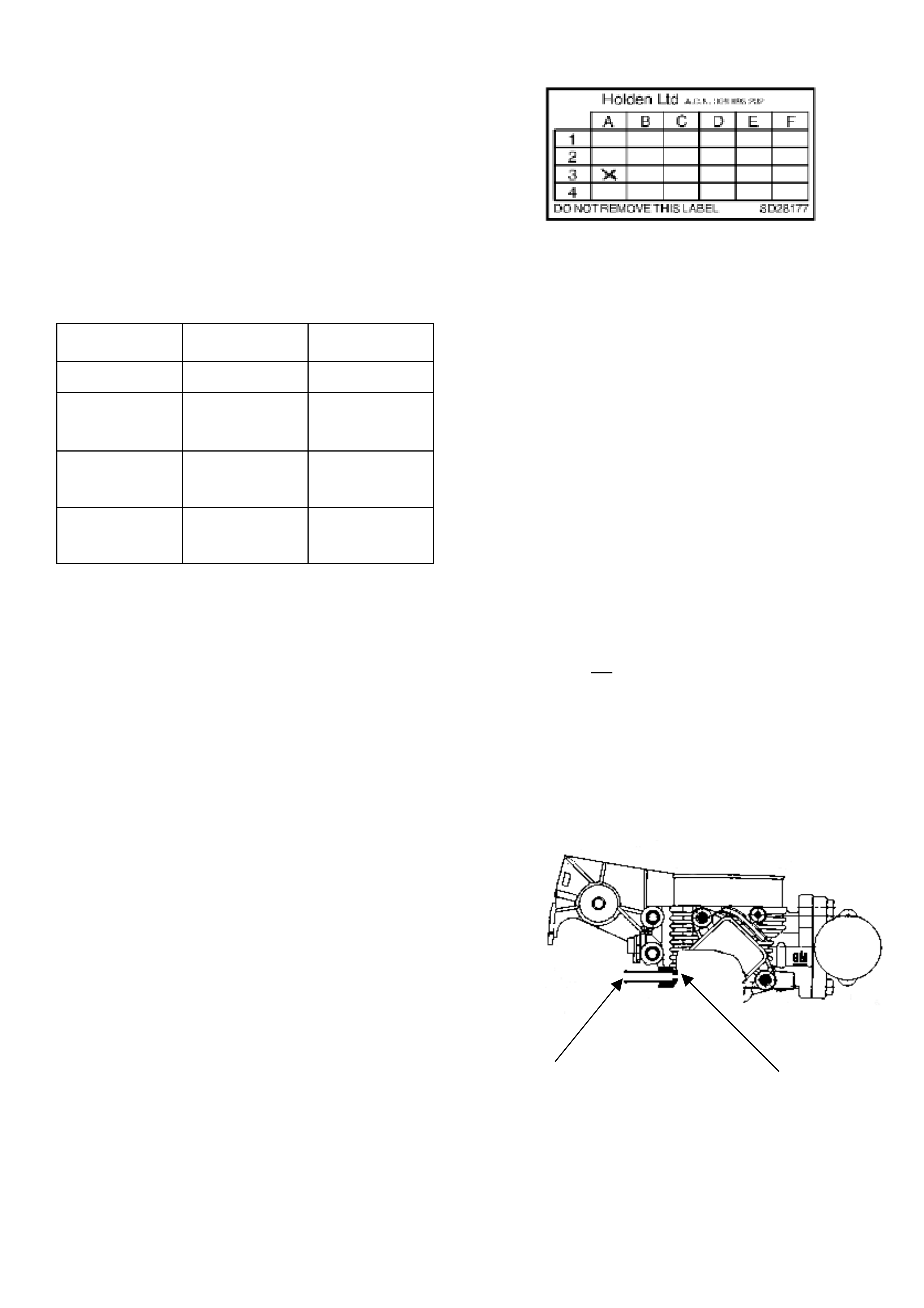
6. Apply a Service History Label (SD-28177) to the
back of the fuse panel cover (lower left corner) and
mark the A-3 co-ordinate on the label.
7. The following PCV hose/port check and clean
procedure must be carried out to all TR Gsi
vehicles and all JR,JS up to
WOLOJBF19YL557427, Build Date 16/02/00
(Breakpoint for introduction of a revised PCV
system that feeds PCV gasses into the lower part
of the inlet manifold.). This check and clean
(where required) ensures no poor idle/stall/DTC
P0100 will result due to blockages, after IACV
fitting.
Blockage of the PCV hose/port will cause the
engine to run on IACV air only at times. Engine
system calibration is based on specific air flow
through the PCV port PLUS IACV air at high
vacuum times (idle/decel) and thus, loss of air flow
through the hose/port can result in poor idle and
possibly stall.
Checking for blockages in PVC hose and port:
While engine is idling, remove the PCV hose from the
cam cover and check if there is vacuum at the free
end of the hose.
If vacuum is not present, remove the PCV hose from
the throttle body port connection and check if there is
vacuum at the port.
(A) - If vacuum is present at the port – replace the
PCV hose. No further action required.
(B) – If there is no vacuum at port then proceed to
clean the port as follows.
The port is shown in the cross section diagram
below, looking from rear of throttle body:
Contamination builds up
in PCV connector. Blocks calibrated hole.
This port may become blocked by contaminants
carried in PCV gas and, over time, the build-up will
block the small calibrated hole in the throttle body.

HOLDEN SERVICE TECHLINE____________________________________________________________FEBRUARY, 2003
10
This hole can be carefully cleaned out as follows:
1. Obtain a 1.5mm Diameter, long drill bit from an
engineering supplies outlet. NOTE: this drill bit
MUST not be larger than 1.5 mm Dia., as the
hole is calibrated. Enlarging the hole will result in
incorrect air flow, and cause driveability or further
code setting problems.
2. Remove the main air intake hose from the throttle
body;
3. Using the 1.5mm Dia. drill bit, carefully insert the
drill into the connection and rotate the drill bit BY
HAND until the deposits in the connection are
dislodged and the drill freely passes through the
calibrated hole into the throttle body inlet passage.
4. Check this by: removing the drill bit from the
throttle body port completely, then open the throttle
blade fully and hold it fully open, insert the drill bit
until it protrudes from the calibrated hole – then
remove drill bit and then close throttle blade.
5. Clean the connection with a solvent or spray
cleaner and remove any debris left in the
connection hole and throttle body;
6. Re-check that the hole is clear using the drill bit,
and re-assemble previously removed components.
PARTS INFORMATION
Obtain IACV kit 92066066 from HSPO.
Part No.: Description: Qty:
92066066 IACV Kit
Kit contains following:
1 - Diaphragm type IACV
1 - Gasket
1 - Patch Harness
1 - Cable Tie
1
WARRANTY CLAIM INFORMATION
Use the following information to claim for the
installation of the new IACV and flash programming
the ECU.
Description Replace IACV
Labour Op. No. J000686
Time 0.6 hr
Failure Code 84
Note: this Labour Operation is useable for vehicles
within and outside new vehicle warranty with the
above noted idle/stall conditions.
Poor AM Radio Reception –
Antenna/Power Leads Loose At Amplifier
TS Convertible
(GROUP 12) TL408-0302
PROBLEM DESCRIPTION
PIRs received indicate that some vehicles experience
poor AM reception due to loose antenna/power lead
connections at the amplifier.
PRODUCTION RECTIFICATION
Antenna/power lead connections at amplifier have
been reworked to ensure tightness from:
ISOVIN: Build Date:
W0L0TGF673B003373 Oct 2002
SERVICE RECTIFICATION
Check tightness of antenna/power lead connections
at amplifier.
This will require removal of the boot trim to access
the left hand quarter panel where the antenna is
mounted.
WARRANTY CLAIM INFORMATION
Description Antenna connector tighten
Labour Op. No. N000420
Time 0.6 hr
Failure Code 27 Loose
Engine Hood Insulator Deleted From
Production
TS With Z18XE 1.8L
(GROUP 1) TL439-0302
From the break point below the engine hood insulator
(Part Number 90559171) has been deleted on all
Astra with 1.8lt (Z18XE) engines. Vehicles fitted with
2.2lt engines will continue to have an engine hood
insulator fitted until further notice.
PRODUCTION CHANGE
ISOVIN: Build Date:
W0L0TGF0835088541 25/11/2002
HOLDEN SERVICE TECHLINE____________________________________________________________FEBRUARY, 2003
11
Brake Pipe Vibrates/Rattles During ABS
Self Test
VTII, VX, VU, VY, WH
(GROUP 5) TL433-0302
PROBLEM DESCRIPTION
During ABS self test, the brake pipes located near
the dash panel can vibrate excessively and cause a
rattle to be heard inside the vehicle.
The cause of this condition is insufficient retention of
the brake pipes in this area.
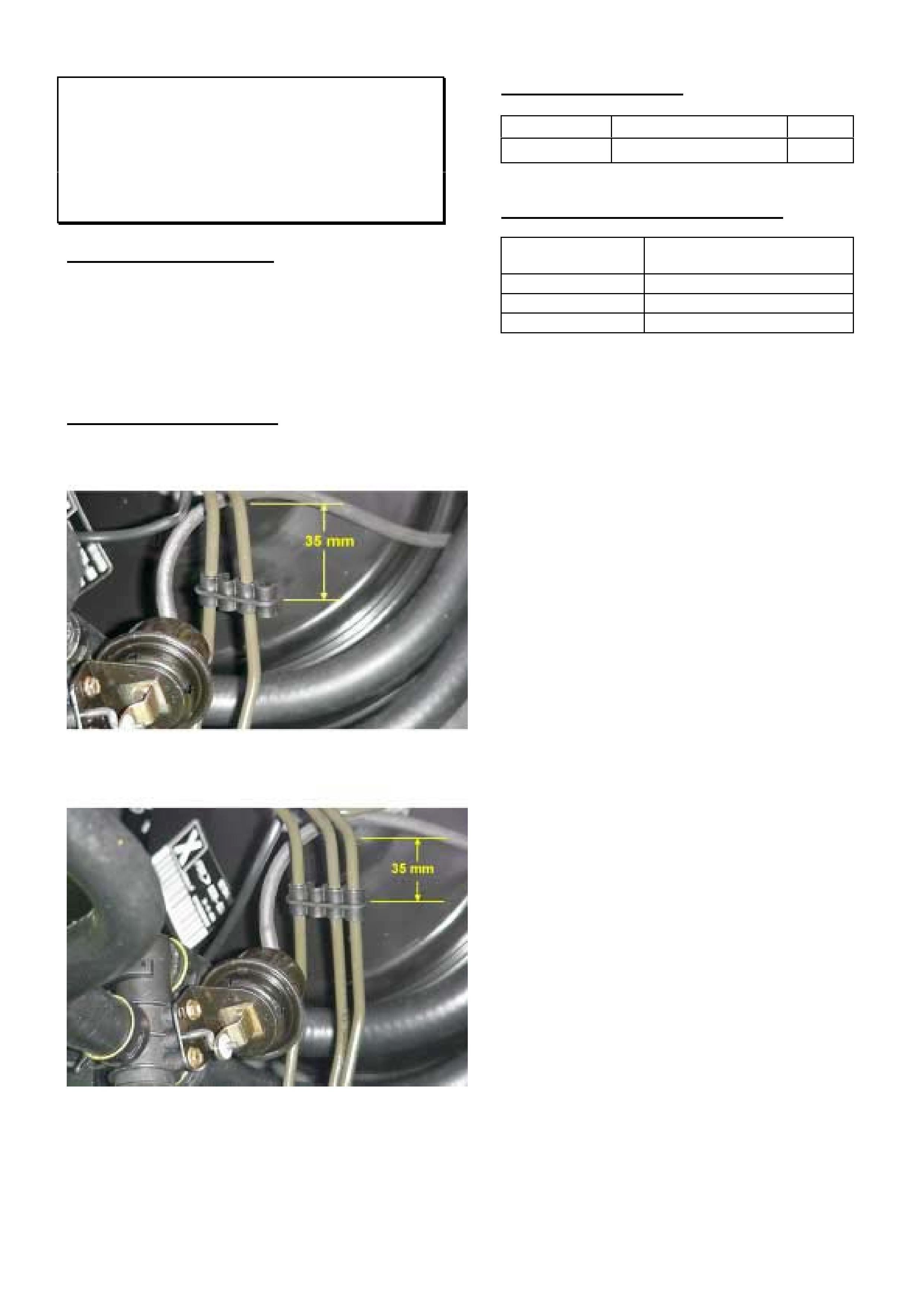
SERVICE RECTIFICATION
Fit additional support clip to pipes in engine bay as
shown in Figure 1 and Figure 2.
Figure 1. Clip added to vehicles with ABS only.
Figure 2. Clip added to vehicles with ABS & traction
control.
PARTS INFORMATION
Part No.: Description: Qty:
92138181 Clip 1
WARRANTY CLAIM INFORMATION
Description Install additional clip to
brake pipes
Labour Op. No. H000240
Time 0.2 hr
Failure Code 28 rattle
HOLDEN SERVICE TECHLINE____________________________________________________________FEBRUARY, 2003
12
New Control Valve Body, Spacer Plate & Gaskets For 4l60-E Auto. Trans.
All V & W with 4L60-E
(Group 7B) REVISED TL203A-0302
This Techline supercedes the previous one in Issue 1, Feb 2002. It is revised by updating spacer plate and gasket kit
part numbers. The previous techline should be destroyed.
All 4L60-E transmissions built after Julian Date “1 ?? D 002 ? ????????” are fitted with a revised valve
body, spacer plate and valve body gaskets. The old and new design valve bodies, spacer plates and
gaskets are shown in Figures 1 to 5. An explanation of the “Julian Date” is given later in this Techline)
SERVICE NOTE:
Whenever repairing transmissions it is vital that the correct spacer plates and gaskets are used.
DO NOT MIX PLATES AND GASKETS FROM DIFFERENT KITS. Refer to the following table for correct
kit usage.
4L60-E built prior to Julian Date 1 002 4L60-E built from Julian Date 1 002
Valve Body Part No. Spacer plate & gasket kit Valve Body Part No. Spacer plate & gasket kit
24210320 - V6
24210321 - V6 S/C
24218822 - Gen3
24221350
24218187 - V6
24218188 - V6 S/C
24218186 - Gen 3
24221137
24221138
24221140
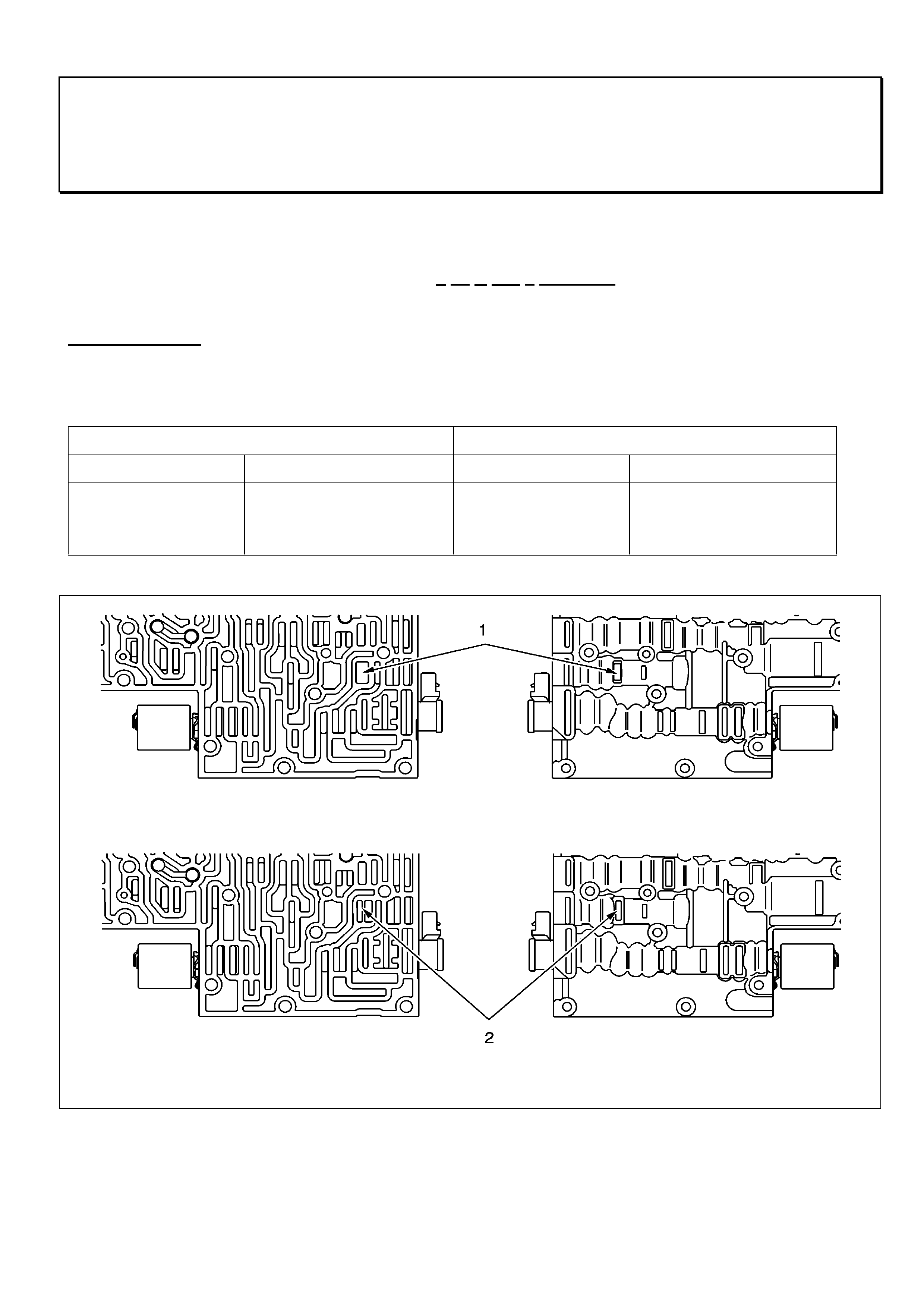
Item 1 Previous Design - shows the wide exhaust port on the TCC regulator valve.
Item 2 Later Design - shows the narrow exhaust port on the TCC regulator valve.
FIGURE 1. Differences between Earlier and Later Design Valve Bodies.
HOLDEN SERVICE TECHLINE____________________________________________________________FEBRUARY, 2003
13
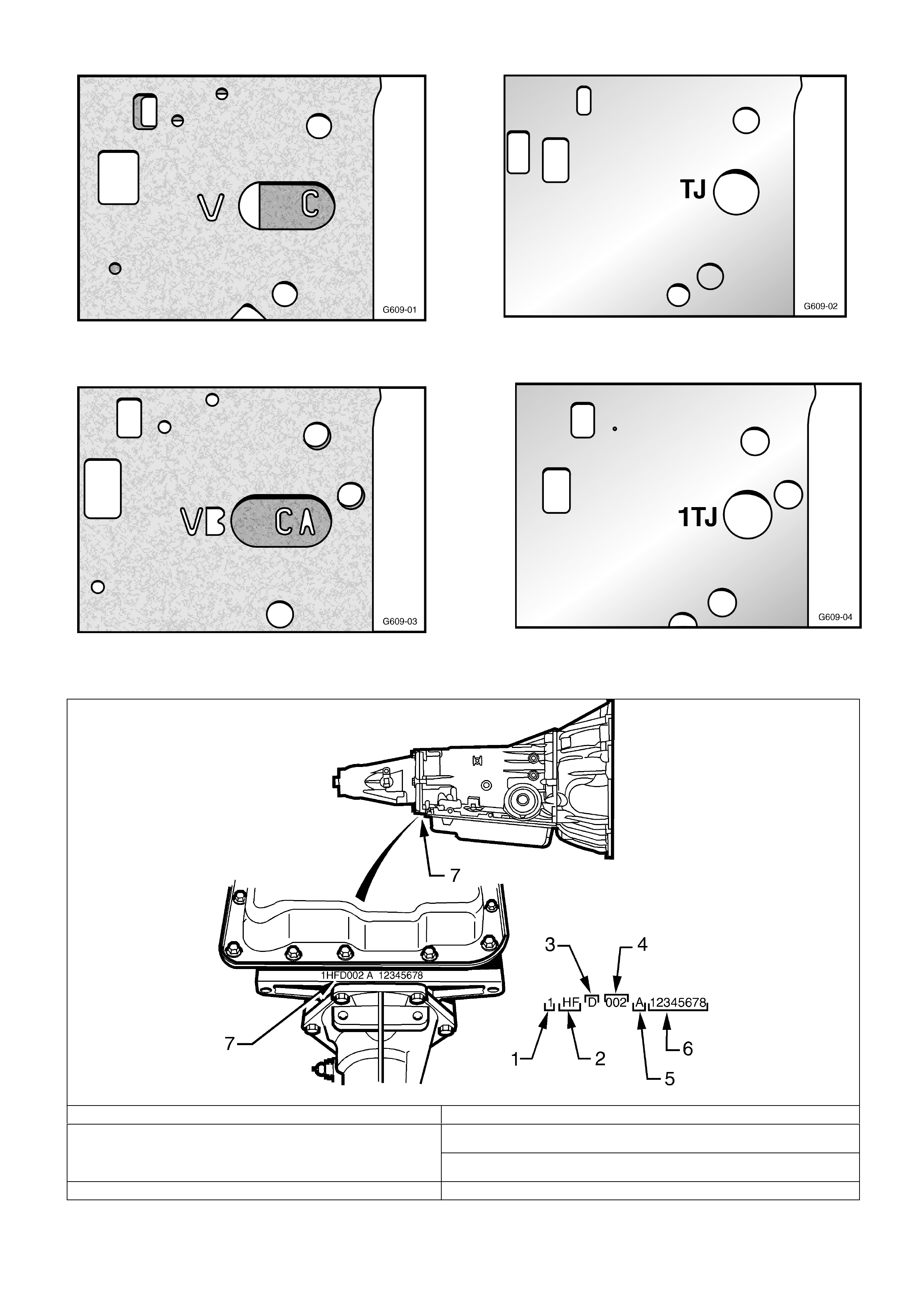
Figure 2. Pre change gasket identifications – “V” for
valve body gaskets and “C” for case gasket.
Figure 3. Post change identification. – “VB” for valve
body gasket & “CA” for case gasket
Figure 4. Pre change spacer plate identification. 2
letter code
Figure 5. Post change spacer plate identification.
“1” is added to the 2 letter code
1. Model Year (1= 2001) 4. Julian Date (Day of the year)
5. Shift built (A,B,J=first shift, C,H,W = second shift) 2. Model: V6 3.8 litre…………………… HF
V6 Supercharged……………HN
Gen3 V8………………… …HP 6. Individual transmission serial no.
3. Transmission Identifier (D = 4L60E) 7. Location of Transmission Identification No.
Figure 6. JULIAN DATE EXPLANATION

HOLDEN SERVICE TECHLINE__________________________________________________________________MARCH, 2003
6
INFORMATION
Holden Assist (Telematics) Clarification
of Modes of Operation
VX / V2 / WH / VY
(GROUP 12) TL444-0303
PROBLEM DESCRIPTION
The Holden Assist Centre advises that some
Retailers are delivering new vehicles to customers
with the Telematics module in the incorrect operating
mode.
This has made it necessary to reiterate the
importance of the information previously published in
All Retailer Letters released in 2001. The bulk of this
information is repeated below.
SERVICE PROCEDURES
New Vehicle Delivery
When the vehicle is delivered from the assembly
plant the Telematics system is in “Pre-delivery
mode”. During vehicle pre-delivery, the “Pre-delivery
mode” of the Telematics module must be disabled
and the “Service mode” enabled using Tech 2.
For all Telematics module programming information
refer to SIP CD, VX / VY Series, Section 12Q .
After the vehicle is handed over to the customer, it is
then the customers responsibility to press the
“Holden Assist” button to register their personal
details with the Holden Assist Centre.
Your Retail outlet may wish to take this opportunity to
demonstrate the features of the Holden Assist
system to your customer.
When all the customer details have been confirmed,
the Holden Assist Centre will, by use of remote
control, disable “Service mode” and place into “Active
mode”.
Servicing
When a vehicle fitted with a Holden Assist system (in
Active mode) is presented to a Retail Outlet for any
service related work it is essential that the system is
placed into “Service Mode” using Tech 2.
In “Service mode”, the Telematics module will ignore
all button presses except for the “Holden Assist“
button. In addition, the unit will not transmit alert
messages for unauthorised entry or if battery is
disconnected. However, the unit will still transmit an
alert message if the SRS system (airbag and/or
seatbelt pre-tensioners) is activated.
On completion of service repairs, use Tech 2 to
disable “Service Mode” (leaving the vehicle in active
mode). Failure to do this will result in 5 beeps each
time ignition is turned ON.
Deactivation & Reactivation
In the situation where a customer wants the Holden
Assist system turned off, Retailers will be required to
de-activate Holden Assist by returning the module to
Pre-delivery mode.
In the situation where the customer changes their
mind and want Holden Assist reactivated, or when
the vehicle is sold and the Holden Assist system is
required by the new owner, the Retailer should
disable Pre-delivery mode leaving the Telematics
module in Service mode.
Summary of Modes of Operation
STATE OF
OWNERSHIP
TELEMATICS
MODULE - MODE
OF OPERATION
RESPONSIBILITY
During Shipping /
Pre-delivery
“Pre-delivery”
Assembly Plant
At vehicle
delivery
“Service”
Retailer
After delivery
“Active”
Customer via
Holden Assist
When Customer
presents for
service
“Service”
Customer via
Holden Assist or
Retailer via Tech 2
When Customer
requests de-
activation
“Pre-delivery”
Retailer
When Customer
sells the vehicle
“Service”
Customer advises
Holden Assist that
they have sold the
vehicle.
Holden Assist place
the account in “Sold”
mode and wait for
reactivation by the
new owner.
Note: To confirm the current mode of operation
refer to the Telematics module data list using
Tech 2.

HOLDEN SERVICE TECHLINE__________________________________________________________________MARCH, 2003
7
SERVICE FIX
Body Control Module- Lock Up / Buzz
VT / VX / VU and V2 (CV6 only)
(Group 12) TL426-0303
This Techline supersedes the previous Techline on
this topic in Issue 1, Feb. 2002, (replace BCM).
PROBLEM DESCRIPTION
Symptoms of BCM Lockup condition are loss of
various BCM related functions resulting in engine no
start, no central locking, etc. This may be
accompanied by a ‘buzzing’ noise emitted from the
BCM.
When the BCM ‘buzzes’ the microprocessor inside
the BCM starts its own self test routine where part of
this test includes switching all BCM internal relays -
hence the ‘buzzing’ sound.
Investigations have found the ‘lock up’ condition is
caused by a static discharge that enters the BCMs’
internal circuitry, causing the BCM to malfunction.
To confirm diagnosis, temporarily remove the BCM
fuse (fuse 31 for vehicles from VT to VXI and fuse 29
for VXII onwards) to reset the BCM. The vehicle
should regain all functionality.
If all the symptoms of ‘lock up / buzz’ have not been
corrected continue with standard vehicle diagnosis.
PRODUCTION RECTIFICATION
BCMs with revised software to prevent “lock-up /
buzz” have been fitted to vehicles from:
BCM Mid Series (p/n 92109212)
ISOVIN: Build Date:
6H8VXK35A2L811439 12/12/01
BCM Low Series (p/n 92109213)
ISOVIN: Build Date:
6H8VXK69A2L812036 13/12/01
SERVICE RECTIFICATION
When presented with a vehicle that has, or is
reported as having, all of the symptoms described
above (engine no start, central locking inoperative
and a buzzing sound from BCM), proceed as follows:
1. Determine if the vehicle is post break point for the
revised BCM or if it has already had the revised
BCM fitted.
If the vehicle does not have the latest BCM
fitted continue to step 2.
If the vehicle already has the post break point
BCM fitted go to step 4.
2. Request a replacement BCM via a Warranty
Changeover Request Form. Refer to All Dealer
Letter 79/00, or SIP, for a copy of the form which is
to be faxed to Australian Arrow. The form must be
completed with all detail as requested.
3. Temporarily return the vehicle to service by
removing the BCM fuse (as previously described)
to reset the module.
4. Fit a slip ring patch harness supplied by HSPO part
number 92108841.
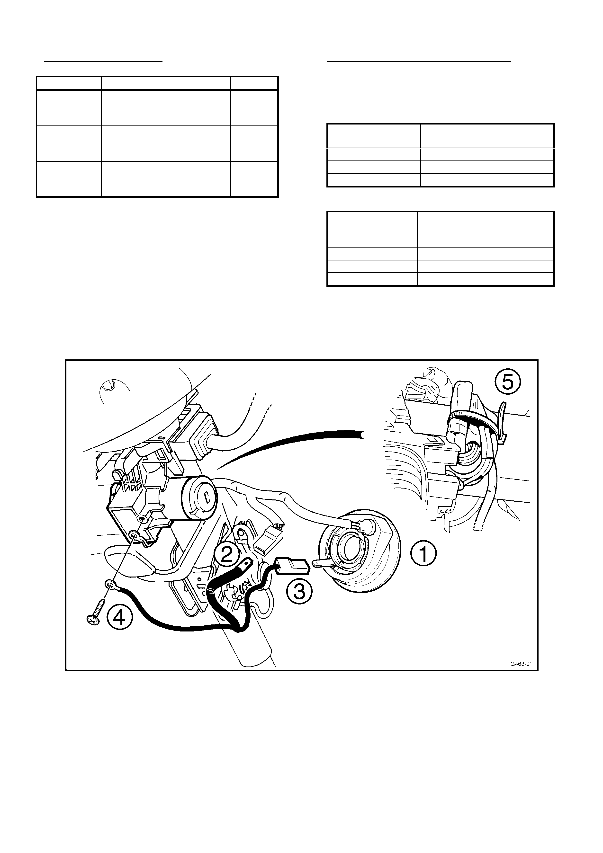
5. Remove the Remote Coded Key Reader (Item # 1
in figure 1), (refer to SIP CD VT SERIES Service
Manual, Section 12J-1, 2.4 Remote Coded Key
Reader).
6. Remove the key reader wiring harness connector
from the key reader and connect it to the male
terminal of the patch harness (Item # 2 in figure 1).
7. Connect the patch harness terminal with black
connector to the key reader terminal. (Item # 3 in
figure 1)
8. Connect the earth lead to the ignition lock housing
earth (underside of steering column). (Item # 4 in
figure 1)
9. Collect and cable tie the excess wiring neatly with
the cable tie, ensuring that there is no interference
when operating the Steering Column lever with the
steering wheel closest to the Instrument Cluster.
(Item # 5 in figure 1)
10. Feed Remote Coded Key Reader globe circuit over
the top of the Ignition lock housing.
11. Reinstall the upper and lower steering column
covers and Remote Coded Key Reader ensuring
that the Reader is aligned correctly (refer to SIP
CD VT SERIES Service Manual, Section 12J-1,
2.4 Remote Coded Key Reader).
HOLDEN SERVICE TECHLINE__________________________________________________________________MARCH, 2003
8
PARTS INFORMATION
Part No.: Description: Qty:
N/A
Revised BCM (from
Australian Arrow via
request form)
1
N/A
Cable tie 2mm x 150mm
1
92108841
Slip ring patch harness
(from HSPO)
1
WARRANTY CLAIM INFORMATION
Use the following warranty claim information for the
installation of the BCM and or Patch Harness to
vehicles experiencing the BCM lock-up condition.
Description Slip Ring Patch Harness
(only) Installation
Labour Op. No. N000423
Time 0.4 hr
Failure Code 29
Description BCM Replacement and
Patch Harness Installation -
Pre Breakpoint vehicles only
Labour Op. No. N000336
Time 0.7 hr
Failure Code 48
Figure 1
HOLDEN SERVICE TECHLINE__________________________________________________________________MARCH, 2003
9
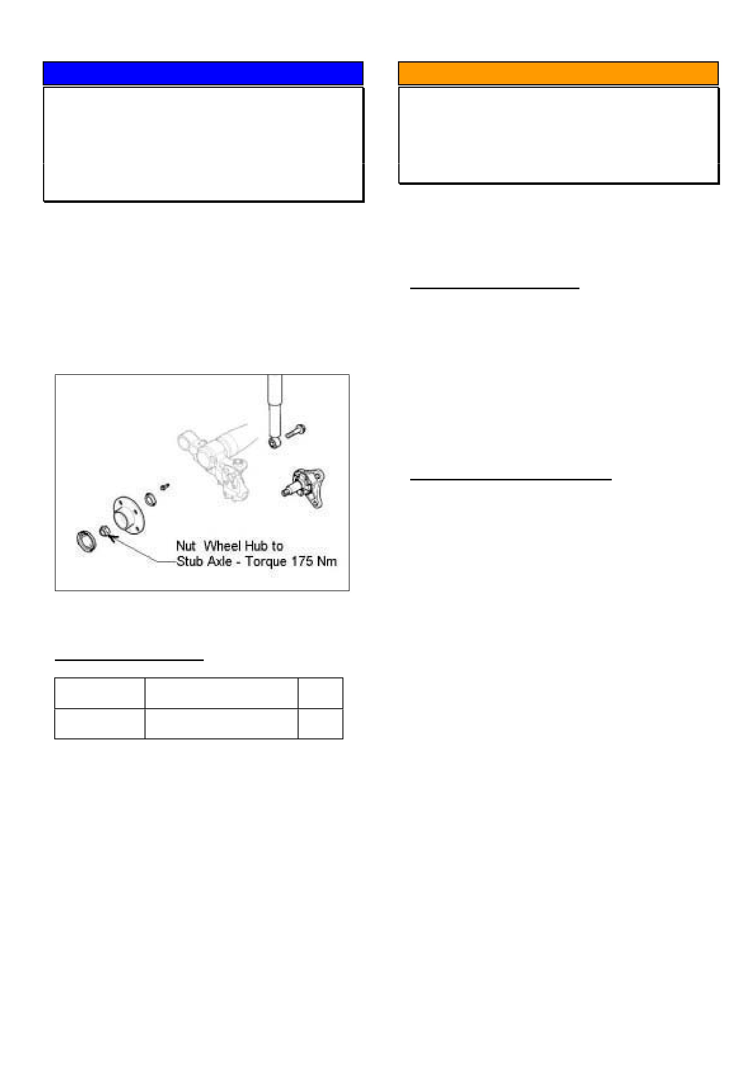
SERVICE PROCEDURE
Rear Wheel Hub to Stub Axle Nut
Replacement Guidelines
XC Barina with rear disc brakes
(GROUP 4) TL453-0303
The following information is provided as it is not
available in current TIS. It will be added to future
versions of TIS.
Whenever the rear wheel hub to stub axle nut is
unscrewed for bearing replacement etc, the NUT
MUST BE REPLACED with a new one and torqued to
175 Nm.
Figure 1.
PARTS INFORMATION
Part No.: Description: Qty
:
09156693 Nut (M20) Rear wheel
hub to stub axle
1
Note. The nut also comes as part of the rear wheel
bearing kit 09196298.
INFORMATION
Clutch Fluid Discolouration
VX,VU,V2
(GROUP 7A) Repeated TL455-0303
This Techline is repeated (previously issued in Issue
5, June, 2002 page 6, but NOT included in Index
pages) to ensure technicians are aware of the
information.
PROBLEM DESCRIPTION
It may be observed on some vehicles that the clutch
fluid darkens in colour after being in service for a
period of time.
Cause
This is a phenomenon that occurs with time due to
the interraction between clutch system rubber parts
with hydraulic fluid. The level of discolouration will
vary with factors such as driving conditions,
underhood temperatures etc.
SERVICE RECOMMENDATION
Laboratory investigations of returned fluid samples
shows that discolouration does not detrimentally
affect performance of the fluid.
Field reports indicate that where clutch system
components and fluid have been replaced for this
condition, the discolouration has reoccurred as
before.
Discoloured clutch fluid should not be replaced in a
normally operating system prior to the interval
specified in the maintenance schedule in the owners
handbook.
HOLDEN SERVICE TECHLINE__________________________________________________________________MARCH, 2003
10
INFORMATION
SERVICE TECHLINES “ON-LINE”
(GROUP 0B) TL458-0303
Service Techlines are available “on-line” at Retailers through the “Holden Lionheart Portal”. The latest Techlines can
be viewed “on-line” immediately they have been approved for publication which means that you can have the latest
Techline information about 2 weeks earlier than you currently receive it. Note; two weeks is about the minimum
period of time it takes to print and distribute Techlines to Retailers via the Technicians Guild program or by direct mail
to Service Managers.
As Techlines are currently prepared on a monthly cycle it is suggested that you check for new bulletins at the
commencement of each month.
The Holden Lionheart Portal should be available on your Sales/Stock Controllers computer and should soon be on
most warranty clerks computers to allow them to access the new On Line warranty system due mid 2003. In order to
have the Holden Lionheart Portal installed on your Service Departments computer you will need to get the necessary
approval from your Retailer’s IT systems administrator.
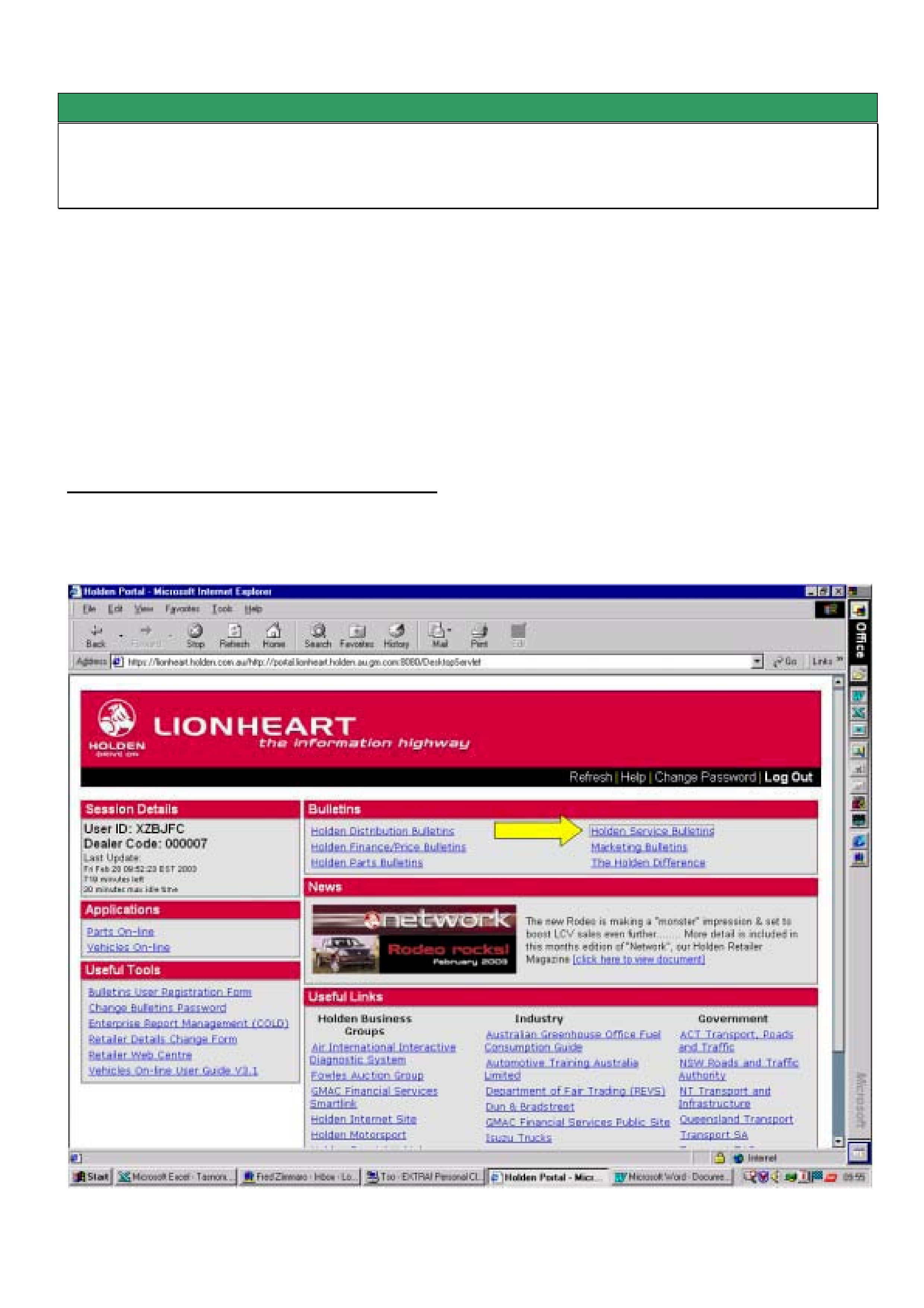
Procedure For Viewing Service Techlines On Line.
Step 1. When the Holden Portal is accessed via Microsoft Internet Explorer the first screen to appear is as follows.
From the section titled “Bulletins” select Holden Service Bulletins.
HOLDEN SERVICE TECHLINE__________________________________________________________________MARCH, 2003
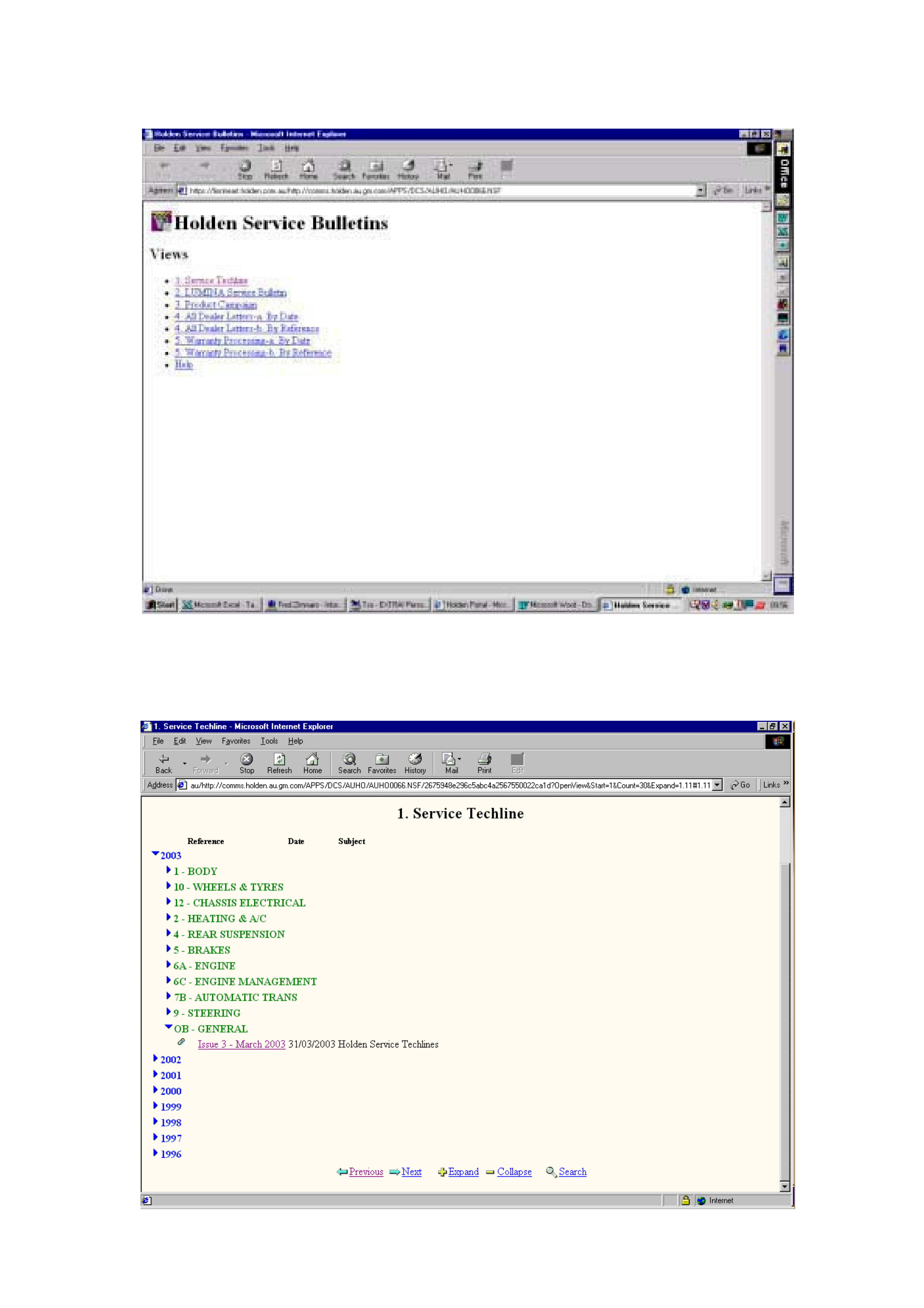
11
Step 2. The next screen to appear is as follows. Select “1. Service Techline”. As you can see from this screen you
can also access other Service information such as Product Campaign Bulletins, All Retailer Letters etc.
Step 3. The next screen to appear is as follows. Select Group OB – General and look for the latest Issue number.
You can then open the file provided you have Acrobat Reader software installed. As Service Techlines are currently
prepared on a monthly cycle it is suggested that you check for new bulletins at the commencement of each month.
HOLDEN SERVICE TECHLINE__________________________________________________________________MARCH, 2003
12
SERVICE FIX
Steering Column Buzz- Height Adjusting
Spring Vibrates
All V & W Models
(GROUP 9) TL440-0303
PROBLEM DESCRIPTION
Some vehicles may exhibit a resonance type buzz
from the steering column area. Typically the noise
may occur when driving at highway speeds on coarse
bitumen roads. The customer may perceive the noise
to come from the steering column, instrument cluster
area or the cockpit module in general
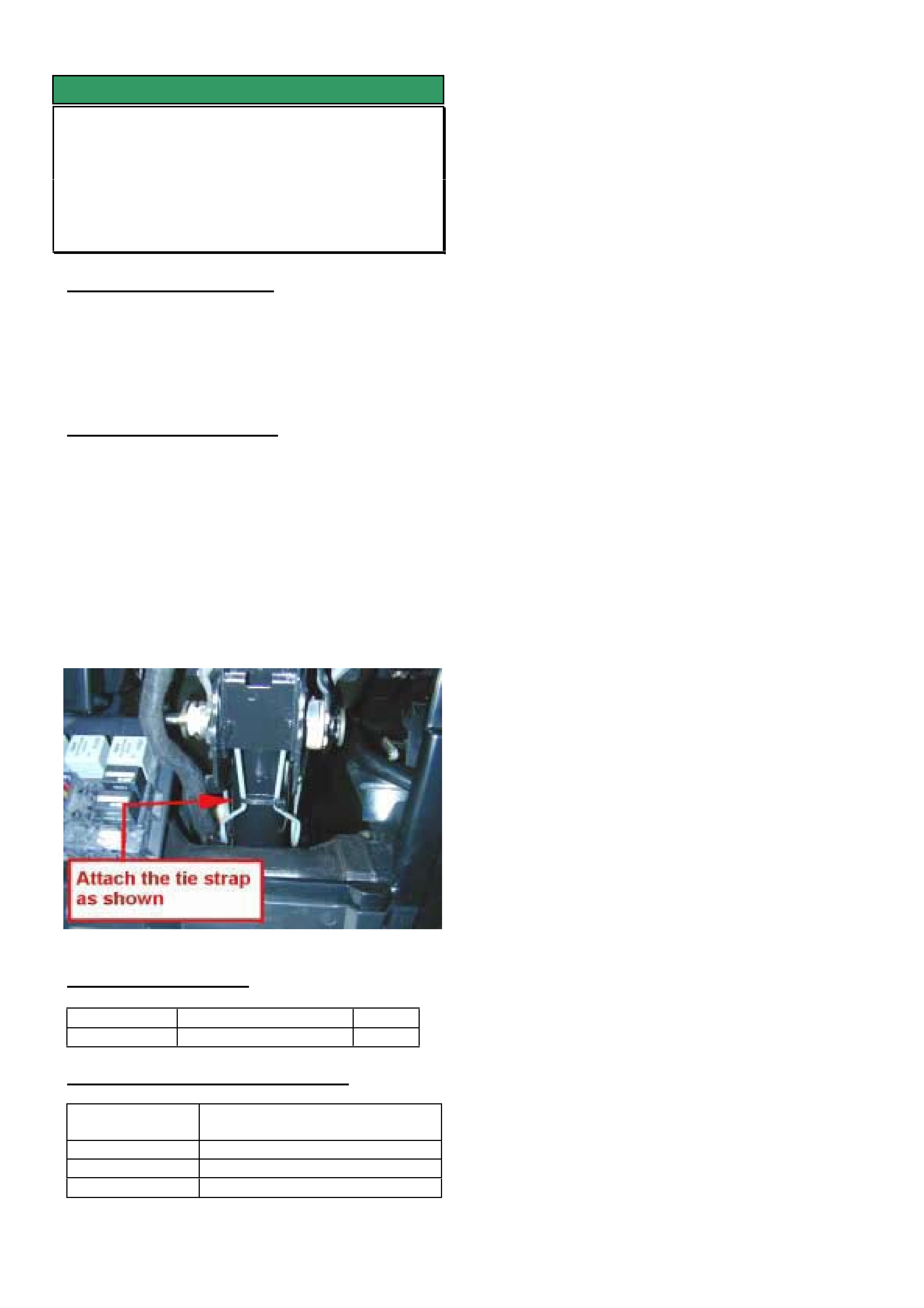
SERVICE RECTIFICATION
Summary: On complaint vehicles apply a tie strap
across the steering column adjust spring.
1. Open the fuse cover.
2. Perform a visual inspection of the steering column
adjust spring to ensure that the spring is
assembled correctly.
3. Attach a tie strap across the spring as shown in
the diagram below. Apply enough tension in the
strap to create 3 mm - 5 mm of deflection in the
spring. Do not overtighten.
PARTS INFORMATION
Part No.: Description: Qty:
92138154 Tie strap 1
WARRANTY CLAIM INFORMATION
Description Steering Column Adjust spring
- attach tie strap.
Labour Op. No. M000190
Time 0.2 hr
Failure Code 36 vibrates
HOLDEN SERVICE TECHLINE__________________________________________________________________MARCH, 2003
13
SERVICE FIX
Ignition Key Jams In Off Position Or Is
Difficult To Turn from Off Position
TS, TT, XC Barina/Combo with “S”
Profile Ignition Keys/Barrels
(GROUP 9) TL421A-0303
This Techline supercedes the Advanced Service
Information in Issue 1, Feb, 2003. It is now
recommended to install the latest revised ignition
barrel instead of reworking existing parts. Production
breakpoints have also been provided.
PROBLEM DESCRIPTION
In some vehicles the ignition key may jam in the
“OFF” position or be difficult to turn from the “OFF”
position.
This condition only affects ignition barrels/keys with
“S” profile. It does not affect those with “D” profile. To
confirm profile type refer to Partfinder® TS
Catalogue, section 06-250A.
This condition results from the hard barrel pin
causing excessive wear of the soft alloy ramp section
of the barrel housing. Refer Figure 1.
PIN RAMP
Figure 1.
PRODUCTION RECTIFICATION
Revised ignition barrels have been fitted to vehicles
from the following breakpoints:
ISOVIN: Build Date:
XC Barina - W0L0XCF6824246086 30/04/02
XC Combo -
W0L0XCF2523030966
30/04/02
TS Astra - W0L0TGF4825195733 May 02
TT Zafira - W0L0TGF752H035990 Aug 02
SERVICE RECTIFICATION
Summary: For complaint vehicles install a new
ignition lock cylinder and tumblers.
To Remove and Reinstall the ignition lock cylinder
refer to TIS 2000 as follows:
TIS Screen ê
êê
ê Select the following ê
êê
ê
Service
Information
Standard Information
Model Astra G/Corsa C/Zafira
Year 2002
Eng. -
Vehicle
Data
Trans. -
Asm.
Group
- Electrical Equipment & Instruments
+Switches, Control Units, Relays, Ign Lock
Standard
Info. Applic’n Repair (Remove,Install,Adjust)
Document List Lock Cylinder for strg. & ign. lock R & R
Tumbler Replacement
The old tumblers must be replaced with the new ones
supplied in the kit. To retain the same key coding,
remove the tumblers one at a time from the old lock
shaft, read the number stamped on the tumbler and
then install a new tumbler with the same code into the
new lock shaft in the equivalent slot.
Note. There are 4 different codes of tumbler and a
total of 10 tumblers per lock cylinder.
PARTS INFORMATION
Part No.: Description: Qty:
92146450 Barrel Kit – Ignition
(S profile)
1
WARRANTY CLAIM INFORMATION
Use Labour Times information in Warranty
Information section of current PV SIP CD
HOLDEN SERVICE TECHLINE__________________________________________________________________MARCH, 2003
14
SERVICE PROCEDURE
Clutch Pedal “Low” – Correct Bleeding
Procedure
V car with Gen III V8 & M/T
(GROUP 7A) TL456-0303
PROBLEM DESCRIPTION
Some retailers have reported difficulty in bleeding
Gen III V8 clutch hydraulic systems, and repeat
customer complaints of “low clutch pedal”, or “hard to
engage gears”.
The cause of these complaints is under investigation.
A number of vehicles have not displayed this
complaint condition until the hydraulic system has
been disturbed during clutch or transmission removal.
During investigation of returned components, it
appears that various methods of bleeding are being
used - with some methods being unsuccessful or
creating aeration of clutch hydraulic fluid.
Because of this, the following SIP procedure has
been repeated in this Techline and is recommended
for use whenever a Gen III V8 clutch hydraulic
system requires bleeding.
CLUTCH HYDRAULIC SYSTEM BLEEDING
PROCEDURE
The clutch hydraulic system must be bled whenever
the hydraulic line has been disconnected, or when a
leak has allowed air to enter the system. Air trapped
in the system can prevent full disengagement of the
clutch.
During bleeding operations, the master cylinder
reservoir must be kept at least half full with hydraulic
brake fluid.
1. Carefully clean any dirt from around the fluid
reservoir cap.
2. Remove the filler cap and top up reservoir as
required, with heavy duty hydraulic brake fluid,
such as Super DOT 4 Plus.
3. Using an 11 mm, 3/8 drive socket, short
extension and socket bar, loosen the slave
cylinder bleeder, located in the upper aperture of
the transmission adaptor plate/clutch housing, on
the left hand side.
4. Then, using just the socket and extension,
tighten the bleeder, using light finger force only.
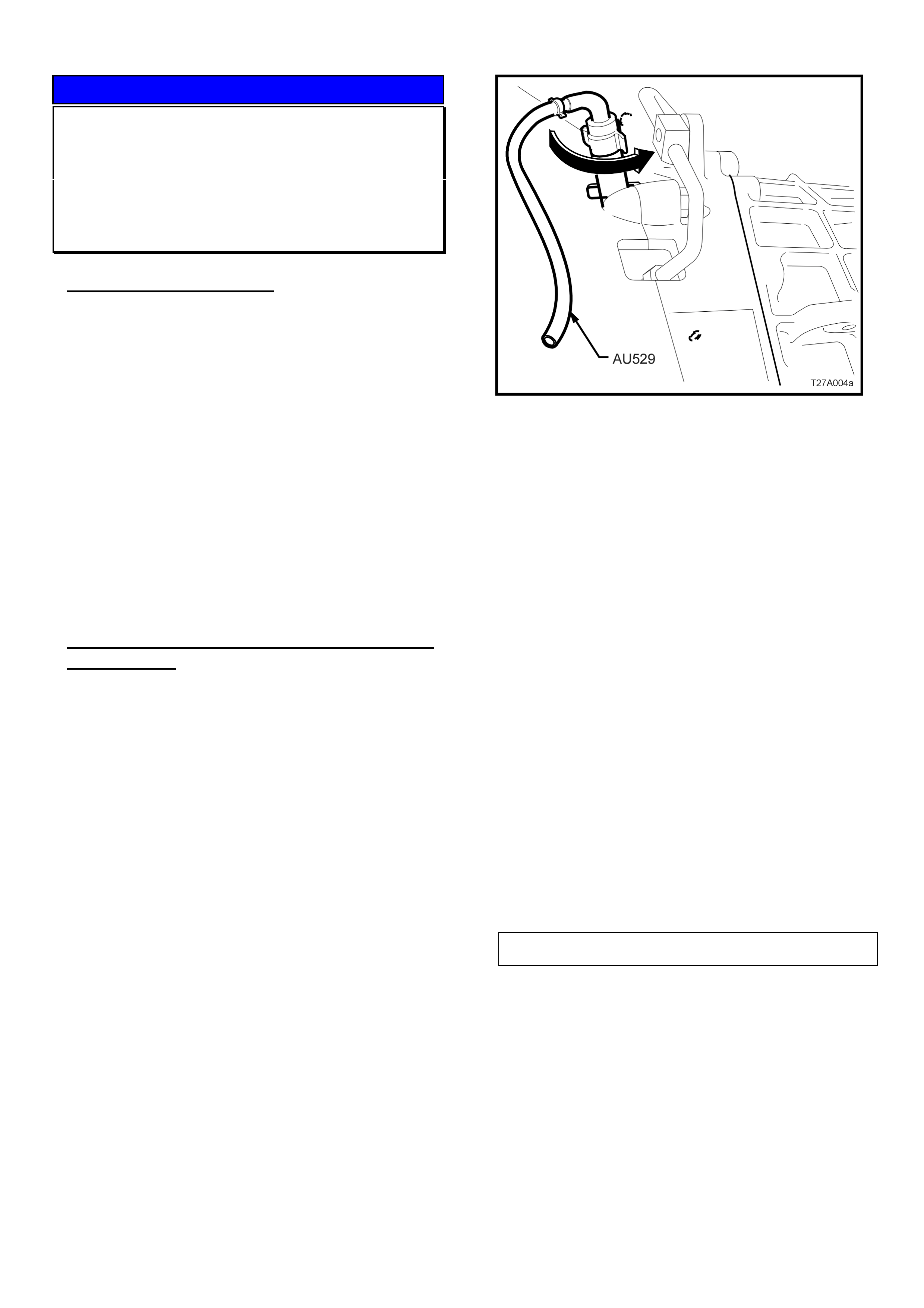
5. Insert the end of the rubber tube of Tool AU529
over the end of the bleeder, positioned at the 9
o’clock position.
6. With the other end of the bleeder tool inserted
into a clean glass container such as a jar, that
has been partially filled with new brake fluid, open
the bleeder 1/4 turn, using the rubber on the
bleeder tool to provide the required grip. Ensure
that the end of the hose always remains
submerged in the brake fluid during bleeding
operations.
7. Using an assistant, slowly depress the clutch
pedal by hand, one single time and, while holding
the pedal depressed, close the bleeder using
Tool AU529. Once the bleeder is closed, the
clutch pedal can be allowed to slowly release.
(ENSURE PEDAL FULLY RETURNS TO THE
“UP” POSITION – lift by hand if required). Repeat
this process until all bubbles cease to appear at
the end of the bleeder hose.
NOTE: Do not pump the clutch pedal
repeatedly during bleeding operations, as
entrapped air will cause the fluid to foam,
making air removal extremely difficult. Also, as
the hydraulic steel piping is routed over the top
of the transmission housing, air can be trapped
in that section.
8. When all air has been removed, close off the
bleeder and remove Tool AU529. With the clutch
pedal still depressed, tighten the bleeder screw to
the correct torque specification.
CLUTCH SLAVE CYLINDER BLEEDER SCREW
TORQUE SPECIFICATION 18 Nm
9. Once all bleeding operations have been
completed, ensure that the reservoir fluid level is
correct.
NOTE 1: “Alternative methods” of bleeding as
mentioned in SIP should not be used on any vehicle
where repeated air entry type symptoms have been
identified. This is to ensure air entry does not occur
during the use of these methods. Only use these
methods as a ‘last resort’.
NOTE 2: Discolouration of fluid is no reason for
replacement of fluid – Refer Service Techline in Issue
3, March 2003.
HOLDEN SERVICE TECHLINE__________________________________________________________________MARCH, 2003
15
INFORMATION
SRTA A/T Exchange Transmission Fitting
Precaution
V & W – with V8 Engine
(GROUP 7B) TL443-0303
Current Condition
Investigation of some returned transmissions from V8
engine vehicles show failure of components is related
to incorrect PCM calibrations being used.
Service Action
Whenever fitting a SRTA transmission, after the
mandatory transmission cooler flow check has been
carried out, technicians should flash program the
PCM with the latest Holden calibration for the vehicle
configuration.
Technicians must also ensure that the SRTA
Feedback form is marked accordingly.
SRTA Action
To remind technicians of this requirement, the
following information will soon be added to all SRTA
replacement transmissions and the Feedback form.
SRTA Feedback Form:
IMPORTANT! On all V8 vehicles confirm that
latest software is installed in the
transmission PCM. Yes
SRTA Transmission Tag:
IMPORTANT NOTICE !
It is essential that you check the transmission PCM
software calibration, ensure that it is the latest for
that model vehicle. If it is not the latest software, it
must be installed before releasing the vehicle.
SERVICE FIX
Stabiliser Bar Drop Link Upper Joint
Bush Splits
VT, VX, VU, VY, WH
(GROUP 3) TL437-0303
PROBLEM DESCRIPTION
The stabiliser bar drop link bushes may fail by
splitting.
PRODUCTION RECTIFICATION
New bushes made of revised rubber with increased
hardness, reduced compression set and improved
performance in high ambients have been fitted to
vehicles from:
ISOVIN: Build Date:
6G1YK54AX3L991753 20/03/2003
SERVICE RECTIFICATION
Summary: Install new bushes as required.
PARTS INFORMATION
Part No.: Description: Qty:
92159373 Bush droplink to strut
asm.
4
WARRANTY CLAIM INFORMATION
Use Labour Times information in Warranty
Information section of current PV SIP CD
HOLDEN SERVICE TECHLINE__________________________________________________________________MARCH, 2003
16
SERVICE FIX
Accessory Drive Belt Tensioner
Rattle/Noise
TR with C16SE, C18SEL, X20XEV engine;
TS with X18XE1 or Z18XE engine
(Group 6Y) UPDATE TL446-0303
This Techline is revised by adding TS model and
changing the case type in warranty claim information.
Please discard previous TR Techline in Issue 1, Feb.
2002.
PROBLEM DESCRIPTION
On some vehicles the following symptoms may be
observed:
• Rattle noisy from front of motor at idle.
• Belt tensioner vibrates excessively up & down.
Investigations show that the alternator induces a high
oscillating load through the accessory belt and
tensioner. This in turn causes the tensioner damping
nylon ring to wear prematurely thus reducing the
damping and causing the tensioner to oscillate and
rattle. The condition is more noticeable when the
engine is cold.
PRODUCTION RECTIFICATION
TS Model: Decoupler pulleys were fitted to vehicles
from:
ISOVIN: Build Date:
W0L0TGF6915264049 N/A
TR Model: Decoupler pulleys were not fitted in
production.
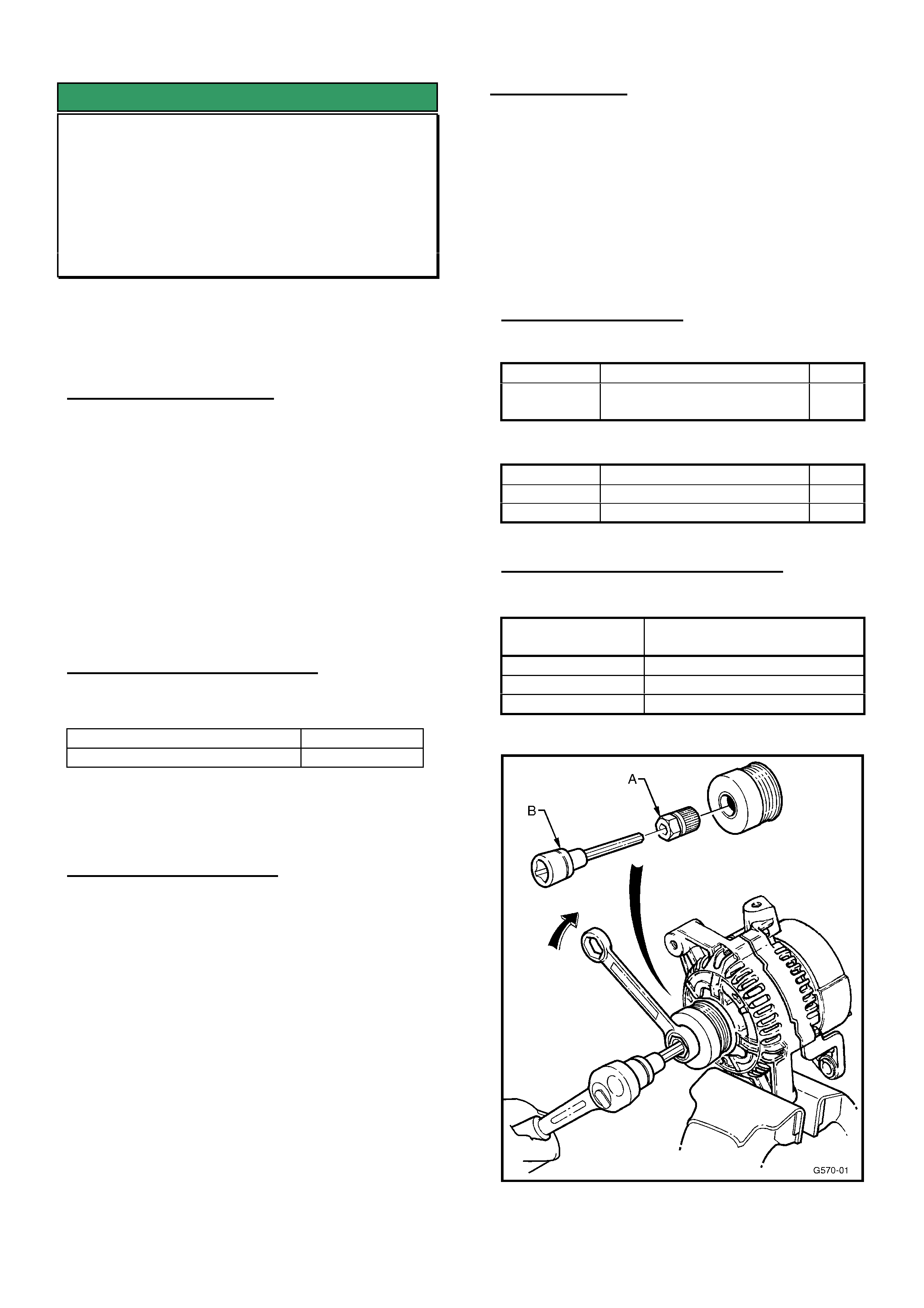
SERVICE RECTIFICATION
Summary: Remove standard alternator pulley and
replace with “decoupler pulley”.
Procedure:
1. Remove alternator assembly from vehicle using
procedure in TIS CD.
2. Remove alternator pulley nut with an impact gun.
3. Install decoupler pulley using special tools A and B
as shown in Figure1.
4. Torque pulley attaching nut to 80 – 100 Nm.
5. Press cap plug into decoupler pulley. It is
important this cap is fitted to prevent the entry of
foreign material.
6. Reinstall alternator to vehicle.
SPECIAL TOOLS
Tool A. - Hazet Tool No. 2592 (Adapter)
Tool B. - Hazet Tool No. 2751 (long hexdrive socket)
For dealerships wishing to purchase their own tools,
contact PB Baumann Tools Australia who will direct
you to the closest Hazet tool Agent.
Telephone: 02 9816 1233.
Email: inf[email protected]om.au
NOTE: These tools can also be obtained on loan
from your Zone Service office.
PARTS INFORMATION
TS:
Part No.: Description: Qty
93170214 Decoupler Pulley and Cap
Plug Asm.
1
TR:
Part No.: Description: Qty
92145105 Decoupler pulley 1
92145244 Plug, sealing cap 1
WARRANTY CLAIM INFORMATION
For vehicles outside of warranty use case type “07.”
Description Install Alternator Decoupler
pulley
Labour Op. No. J000698
Time 1.0hr
Failure Code 28 Rattles
Figure 1.
HOLDEN SERVICE TECHLINE__________________________________________________________________MARCH, 2003
17
SERVICE PROCEDURE
Entertainment System Additional Code
Indexes
VY, V2 Series II
(GROUP 12) TL450-0303
Due to a running change of components within the
VY and V2 Series II Blaupunkt Entertainment system
it has been necessary to add some additional code
indexes. This information is provided below as it is
not yet been added to PV SIP.
SERVICE RECOMMENDATION
When installing an upgrade or warranty replacement
radio, it is necessary to program the code index
within the unit to configure it to the particular vehicle.
To program the code index refer to PV SIP Section
12D / Entertainment System / 3.11 Program / F0:
Program Code Index.
Use the following table to obtain the correct code
index.
• If the code index in the replacement radio is
between 001 and 006 use column A,
• If the code index in the replacement radio is
between 007 and 012 use column B, in the
table below.
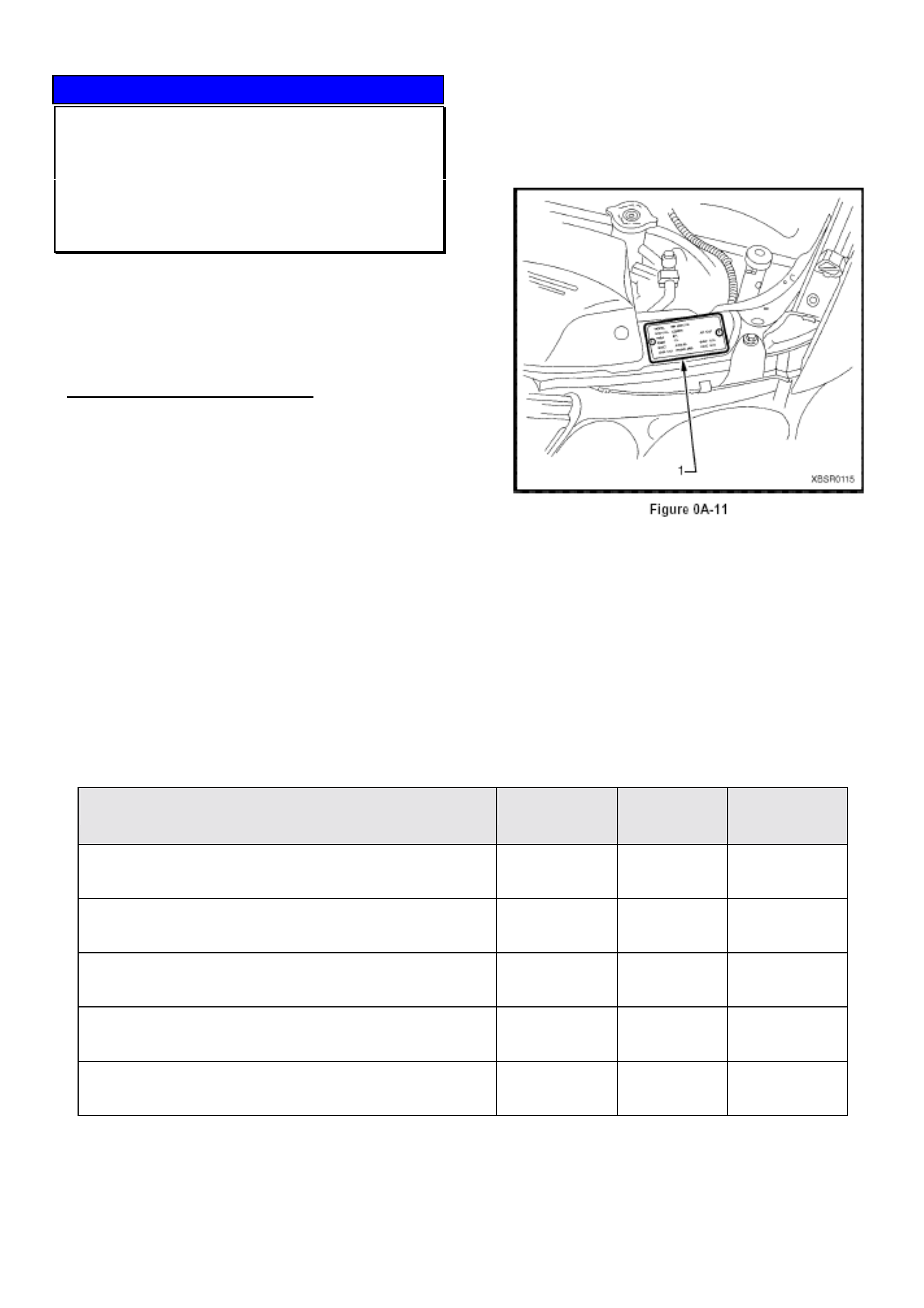
Note: The vehicle description 8VK or 8VL refers to its
luxury level and is found on the Body and Option
plate which is located on the radiator support panel
as can be seen below.
Vehicle
CD unit
Code Index A
Code Index B
All 8VK (Executive, Acclaim, SS, CV6 etc) Except 8VK80
Single
001
007
All 8VK (Executive, Acclaim, SS, CV6 etc) Except 8VK80
6 Stack
001
007
All 8VL (Berlina)
6 Stack
001
007
8VK80 & 8VK03 (Ute / Cab Chassis)
Single
003
009
8VK80 & 8VK03 (Ute / Cab Chassis)
6 Stack
003
009

HOLDEN SERVICE TECHLINE__________________________________________________________________MARCH, 2003
18
INFORMATION
P/S Pump Pulley Replacement
All with Gen III V8
(GROUP 9) TL424-0303
When replacing a power steering pump it is
necessary to remove the pump pulley and fit it to the
replacement pump – refer to May 2001 Service
Techline bulletin: “Removing Pulleys & Hubs From
Power Steering Pumps – Repac Returns Precaution”.
Difficulty may be experienced when removing power
steering pump pulleys.
PRODUCTION RECTIFICATION
Revised power steering pump pulleys with extended
hub centres were introduced into production from:
ISOVIN: Build Date:
6H8VXK69F2L858938 03/05/02
SERVICE RECOMMENDATION
Summary: Three possible installations will be seen in
service – use one of the following procedures as
required:
1. Pumps with standard pulley and pulley location
on pump shaft:
• Pumps before L858938 are able to be removed by
existing special tools as per the relevant SIP
information.
2. Pumps with ‘Relocated’ Pulleys:
Some power steering pump pulleys have been
pressed further onto the power steering pump shaft
to correct engine drive belt squeal - as per Techline
of May, 2001, Issue 5. On these pulleys, the SIP CD
“Method 2” special tool will not fit.
• Remove pulley using press plates under the
pulley and refit using tools shown in the “Method
1” procedure in SIP CD, VT Series II
“Power Steering Service Operations” section.
3. Pumps with Extended Hub Pulleys:
Vehicles with pumps built after L858938, or with
current design pulleys ex-HSPO have a longer hub
centre. On these pulleys, the SIP CD “Method 2”
special tool will not fit.
• Remove pulley using press plates under the pulley
and refit using tools shown in the “Method 1”
procedure in SIP CD, VT Series II Power
Steering Service Operations section.
Note: These same situations will also be evident
when replacing a leaking pump front seal.
Caution:
High press pressures may be required to remove
some pulleys because of the interference fit that
exists. Should it not be possible to remove the power
steering pulley using press plates as per SIP, the
pump will need to be replaced. Note this on the
Defective Material Tag.
PARTS INFORMATION
Pulleys with the ‘longer’ hub centre are the only
replacement parts available from HSPO.
INFORMATION
Removing Pulleys & Hubs From Power
Steering Pumps Returned To Repac
VX, VU, V2, VY, WH
(GROUP 9) REPEAT TL425-0303
This Techline bulletin is repeated from May 2001 for
the benefit of technicians and Warranty personnel –
to ensure power steering pumps are dismantled and
returned in the correct manner – this will avoid
charge-back action being taken by REPAC.
--------------------------------------------------------------
Please circulate this Techline to your Warranty
personnel.
--------------------------------------------------------------
A number of power steering pumps returned to
REPAC under warranty still have hubs (on V6
pumps) and pulleys (on V8 pumps) assembled to
them.
This is a reminder to retailers that hubs and pulleys
can be easily removed from pumps using a standard
workshop hydraulic press with special press plates.
For special tools and removal procedures refer to
Passenger SIP CD, VT Series 1 Service Information,
Section 9A, Parts 3.10(V6) and 3.11(V8).
Provided there are no obvious signs of damage, a
“removed” hub or pulley can be reinstalled onto the
new pump following the installation procedures
shown in SIP.
Warranty Clerks NOTE:
The standard time for pump R & R (labour op.
M147000) includes an allowance for hub removal.
In light of the above, all retailers are requested to
remove pulleys and hubs from pumps before
returning them to REPAC.

HOLDEN SERVICE TECHLINE__________________________________________________________________MARCH, 2003
19
SERVICE FIX
Antenna Extends and Radio Turns on by
Itself
VY / V2 Series II
(GROUP 12) TL445-0303
PROBLEM DESCRIPTION
There have been several reports where customer
advises that they have returned to their vehicle to find
the antenna is up and the radio on.
In some situations the customer will also find their
wipers going if they have switched the ignition off
while they are running.
This problem only occurs on vehicles, which have a
low or mid series BCM and also have electric
antenna.
SERVICE RECTIFICATION
The cause of this problem is water entry in to the two
pin connector at the electric antenna.
1. To rectify this problem, clean the water out of the
antenna connector.
2. Confirm that all seals are correctly located
around each wire in the connector and between
the mating surfaces of the connector.
3. Apply Nyogel grease to the connector cavity and
then re-assemble the connector.
4. Ensure that the connector positively engages.
Please PIR all cases including information about seal
condition and possible water entry points.
PARTS INFORMATION
Part No.: Description: Qty:
92146329 Nye Nyogel 760G
Grease – 30cc syringe
1
WARRANTY CLAIM INFORMATION
Description Dry water out of antenna
connector
Labour Op. No. N000426
Time 0.4 hr
Failure Code 51
INFORMATION
Tech 2 Unable to Communicate with
Instrument Cluster
V2 Series 2 (CV8 only)
(GROUP 12) TL447-0303
PROBLEM DESCRIPTION
There have been several reports of vehicles, where
Tech 2 is unable to communicate to the instrument
cluster.
When this situation occurs Tech 2 displays “Unknown
ECU”.
SERVICE RECTIFICATION
This problem can be rectified in service by using
Tech 2 software version 12.0 which will be released
on TIS 2000 version 40.
Update

HOLDEN SERVICE TECHLINE__________________________________________________________________MARCH, 2003
20
INFORMATION
Brake And Clutch Fluid Colour Changed
In Production
VY, V2, WH
(GROUP 5 & 7A) TL438-0303
The brake and clutch fluid used in production for the
above models is changing colour from green to light
amber.
The new amber coloured fluid is identical in
specification to the green fluid except for the colour.
The fluids can be mixed in service in those situations
where the correct colour fluid is not available.
PRODUCTION BREAKPOINT
The amber coloured brake and clutch fluid is planned
for introduction into vehicles in the first week of April
2003.
Breakpoints will be published when they become
available.
ISOVIN: Build Date:
TBA TBA
PARTS INFORMATION
Part No.: Description: Qty:
92026651 Brake/clutch fluid
500ml green
1
TBA Brake/clutch fluid
500ml amber
1
DIAGNOSIS HINT
Radio Volume - Erratic Operation
Intermittently
VY / V2 Series II
(GROUP 12) TL475-0303
PROBLEM DESCRIPTION
Customers may report the following symptoms with
their radio:
The volume intermittently increases to maximum, or
the volume indicator increases to maximum while the
radio mutes or the radio mutes.
The above symptoms can occur when any of the
speaker circuits are interrupted in the following ways.
1. Intermittent Short to Ground or Battery
Supply
The volume indicator display on the radio will
increase to the maximum or decrease to the
minimum reading and when the volume knob is
turned it will go in the direction indicated on the
display.
E.g. Maximum indication on the display will result in
maximum volume on all speakers.
Note: In some situations it may not be necessary to
turn the volume control knob to have the volume
change.
2 Constant Short to Ground or Battery
Supply
The volume indicator on the radio may display the
maximum or minimum reading and the radio will
mute.
3. Short between both Positive and Negative
Speaker Wires
The radio will mute the affected circuit until the short
is removed.
PIRs Required
Technicians are requested to submit PIRs on any
vehicles in which the above conditions are found.
HOLDEN SERVICE TECHLINE__________________________________________________________________MARCH, 2003
21
SERVICE FIX
Door Checklink Bolts Loose
TS, TT, JS, XC
(GROUP 1) UPDATE TL285B-0303
This Techline supercedes the previous one in Issue
6/2002. It is revised by adding requirement to apply
threadlock compound to new checklink bolts.
PROBLEM DESCRIPTION
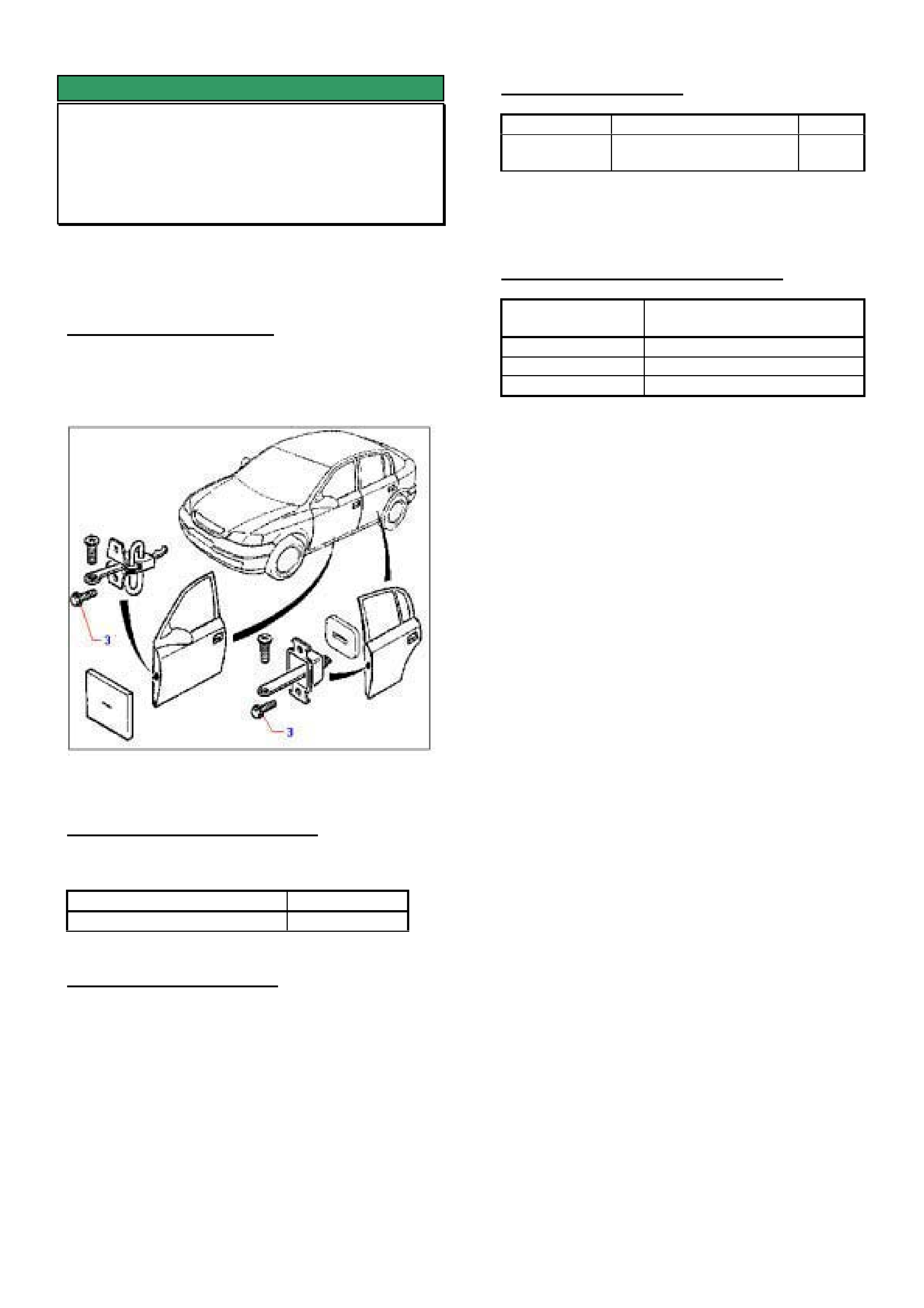
On some vehicles the door checklink attaching bolts
may loosen. Refer item 3 in Figure 1.
Figure 1.
PRODUCTION RECTIFICATION
Revised checklink attaching bolts have been fitted to
vehicles from:
ISOVIN: Build Date:
W0L0TGF4815283442 05/06/2001
SERVICE RECTIFICATION
On complaint vehicles, ensure that the latest
checklink attaching bolts p/n 13104167 are installed
and torque to 4.5 to 5.0 Nm.
IMPORTANT: Apply threadlocking compound Loctite
243 (or equivalent) to the bolt threads prior to
installation. Failure to do so may result in the bolts
coming loose again.
PARTS INFORMATION
Part No.: Description: Qty:
13104167 Bolt Checklink to door. 2 per
door
Threadlocking compound Loctite 243 can be
obtained from most industrial equipment suppliers.
WARRANTY CLAIM INFORMATION
Description Bolt/pin check asm. all four
doors - Replace
Labour Op. No. C634000
Time 0.5 hr
Failure Code 40 (Noisy)
If replacing checklink bolts on individual doors, use
Labour Times information in Warranty Information
section of current PV SIP CD
HOLDEN SERVICE TECHLINE_________________________________________________________________ APRIL, 2003
6
SERVICE FIX
Battery Discharge -Telematics
VX / WH / V2 Series 1
(GROUP 12) TL476-0304
PROBLEM DESCRIPTION
Customers may complain of the vehicle battery going
flat prematurely or receiving repeat low battery alert
calls from Holden Assist when the vehicle is left for
several days.
PRODUCTION RECTIFICATION
Revised software to reduce the current draw of the
Telematics module has been installed from.
ISO VIN Build Date
6G1HK53B63L933021 25/10/02
SERVICE DIAGNOSIS
Ensure the Telematics module in the vehicle has
been placed in Service Mode.
Confirm that the vehicle has no other problems
causing excessive current draw by performing a
Battery Current Draw Test as described in SIP
Section 12A Battery & Cables.
Place the BCM into pre-delivery mode before
performing a Battery Current Draw Test to eliminate
the current draw from the interior illumination relay.
The current draw specification for a vehicle which has
Telematics fitted should be approximately 140 mA
after the vehicle has been left for a period of five
minutes.
Current draw above 140mA
If the Battery Current Draw proves to be higher the
source of the extra current draw should be isolated
and repaired.
Current draw below 140mA
If the Battery Current Draw is approximately 140 mA
or lower the Telematics module BIM software version
number should be checked.
The Telematics System Identification screen can be
viewed by using Tech 2 and making the following
selections; F0: Diagnostics / (1) 2001 / VX
Commodore / F3: Body / Telematics Module
This Identification screen will list the BIM software
version number. If this number is 71 or lower, the
module will require a software upgrade as follows.
For version numbers above 71 no further action is
required.
SERVICE RECTIFICATION
To have a customers module upgraded with the
revised software, complete the Telematics Change
Over Request Form located in the Change Over
section of SIP and fax it to Australian Arrow on (03)
9775 0954.
Australian Arrow will organise for a bridging
connector, acknowledgement form and a return
prepaid box to be shipped to your Retail Outlet.
It will be necessary to re-book the customer’s vehicle
once the package arrives.
When making the customer booking explain to the
customer that if they wish to have the software
upgraded in their vehicle they will be without the use
of the Telematics for a period of a maximum of ten
working days.
Removal of the Telematics module and fitting of the
bridging connector should only take approximately 15
minutes.
Before fitting the bridging connector ensure the
customer has completed and signed the
acknowledgement form. The original should be
filed for future reference.
Remove the Telematics module from the customers
vehicle and fit the bridging connector; this will allow
the customer to drive their vehicle until their
Telematics module with the revised software returns
from Australian Arrow.
When the revised Telematics module returns from
Australian Arrow it will be necessary to re-book the
customers vehicle to re-fit the Telematics module.
When making the customer booking for the module to
be re-fitted advise the customer that the vehicle will
be required for a minimum of two hours.
Once the revised Telematics Module is fitted it is
important to perform the following steps;
1. Use Tech 2 to confirm the VIN number in the
Telematics Module matches the actual VIN
number of the vehicle.
2. Use Tech 2 to disable Pre Delivery mode (you will
require TIS approval to perform this operation) and
program the Code Index using index number 001.
3. Perform a Telematics On Board Diagnostic
System Check as per the SIP Section 12Q
Telematics / 5 Diagnostics.
4. Set the BCM battery saver mode to 10 minutes.
5. Check vehicle battery condition; charge if required.
6. The vehicle can then be returned to the customer.
WARRANTY CLAIM INFORMATION
Description Software upgrade
Telematics Module
Labour Op. No. N000402
Time 1.0
Failure Code 50

HOLDEN SERVICE TECHLINE_________________________________________________________________ APRIL, 2003
7
INFORMATION
Holden Assist (Telematics) GPS Location
Difficulties On Initial Activation
V2II / VY / WK
(GROUP 12) TL478-0304
PROBLEM DESCRIPTION
The Holden Assist Centre advises that they are
having difficulties locating some new vehicles when
customers or Retailers perform a Holden Assist
button press for the first time.
SERVICE PROCEDURE
Due to the time taken for the Telematics module to
gain a GPS location (Latitude & Longitude), when
activated for the first time (eg new vehicle or the
module has been replaced) it is necessary to perform
the following process.
1. Before delivery to the customer the Telematics
module should be taken out of “pre-delivery”
mode and placed into “service” mode using
Tech 2.
2. Park the vehicle outside for at least one hour in a
location where the sky is clearly visible.
SERVICE FIX
Unable To Select Gears
VT,VX,VU,V2,VY with Gen III M/T
(GROUP 7A) TL475-0304
PROBLEM DESCRIPTION
In some cases where excessive effort is used for
gear changes, the Remote Shifter Mechanism front
pivot ball may dislodge from the nylon retainer. This
results in being unable to select gears.
If a customer complains of no gear selection and
rubbery shift feel, proceed with Service Rectification.
SERVICE RECTIFICATION
Summary: Install new remote shifter from HSPO
after fitting reinforcing plate kit obtained from TAS.
Note: For detailed procedures on removing and
reinstalling remote shifter refer to PV SIP CD.
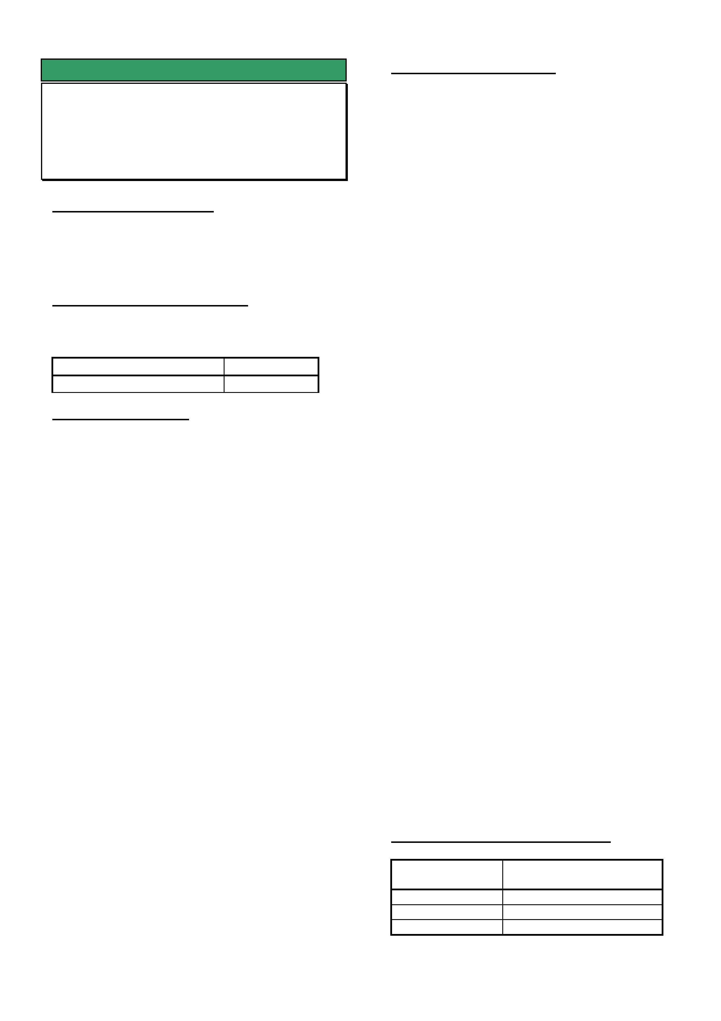
1. Inspect remote shifter to determine if front pivot
ball has dislodged from nylon retainer. Refer to
Figure 1.
2. Once failure has been confirmed, remove remote
shifter assembly from transmission.
3. Check for damage to offset lever cup as shown in
Figure 2. Replace if damaged . If required, order
a new offset lever from HSPO.
4. Order a new remote shifter assembly from HSPO
using part numbers from latest Partfinder.
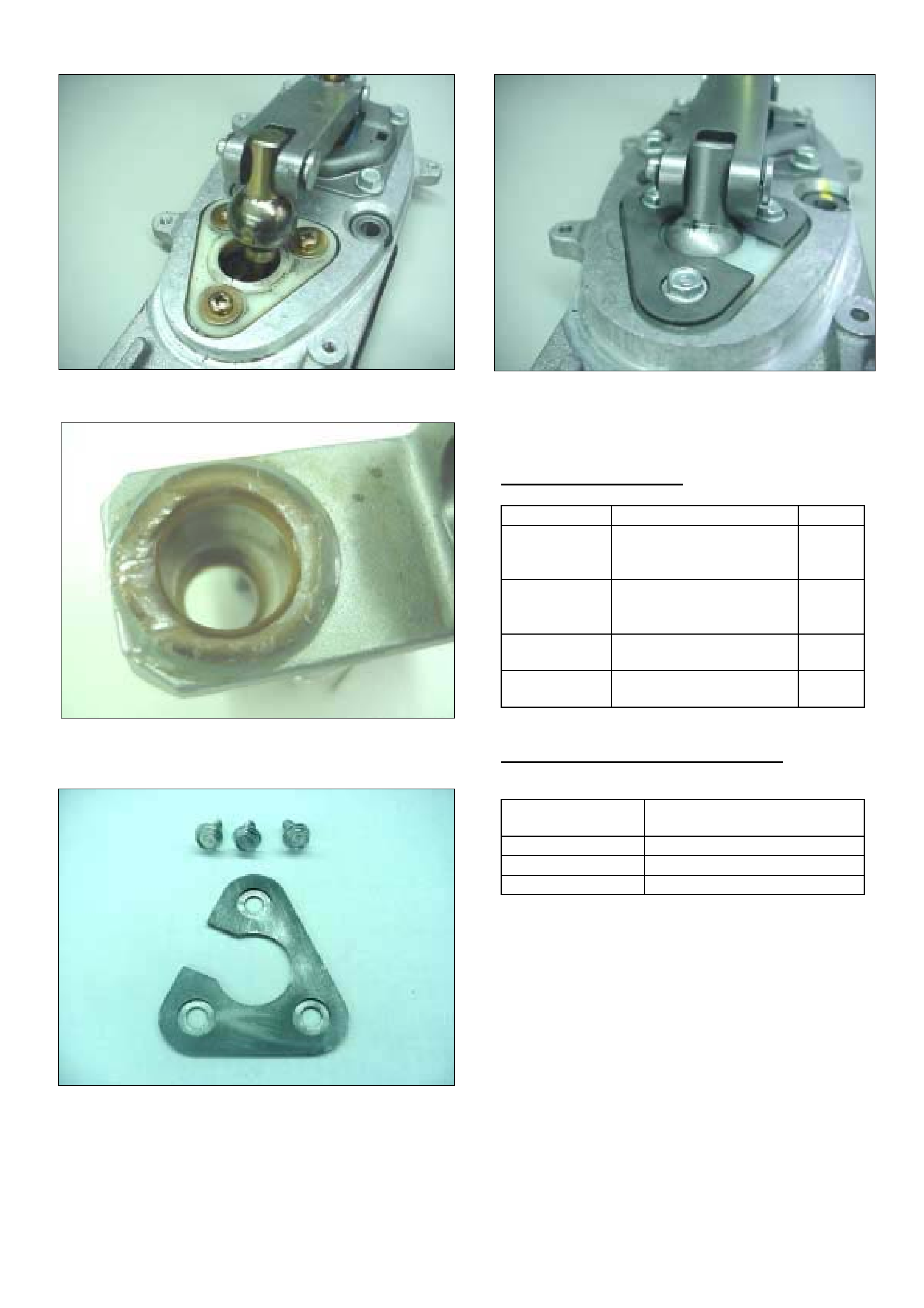
5. Have your nominated TAS contact person ring
TAS for a reinforcing plate service kit. The service
kit contains 1 steel reinforcing plate and three
attaching screws as shown in Figure 3.
NOTE: Prior to fitting the new remote shifter to the
transmission, fit the steel reinforcing plate service
kit on top of the triangular nylon retainer as per
instructions 6 to 8 below:
6. Remove and discard the 3 original attaching
screws for the triangular nylon retainer.
7. Slide steel reinforcing plate over the top of the
nylon retainer. This plate only fits in one direction.
Ensure countersinks for the screws face upwards.
8. Use the 3 screws provided with the service kit to
attach the steel reinforcing plate. Screw torque:
3.5 - 5.5 Nm. Refer to Figure 4 for illustration of
reworked assembly.
9. Fit new offset lever to transmission (if required).
10. Fit new remote shifter with steel reinforcing plate.
HOLDEN SERVICE TECHLINE_________________________________________________________________ APRIL, 2003
8
Figure 1. Failed Remote Shifter
Figure 2. Typical damage to offset lever cup
Figure 3. Steel Reinforcing Plate Service Kit
Figure 4. Remote Shifter with Steel Reinforcing Plate
installed.
PARTS INFORMATION
Part No.: Description: Qty:
92144962 Shifter asm – Pre VY
models up to L832047
(21/2/02)
92146309 Shifter asm – Pre VY
models from L832048
(21/2/02)
1
92146797 Shifter asm. – VY
1
Contact TAS Reinforcing plate
service kit
1
WARRANTY CLAIM INFORMATION
Description Replace remote shifter asm
& fit reinforcing plate kit
Labour Op. No. K000288
Time 2.7 hr
Failure Code 71 Pulled loose

HOLDEN SERVICE TECHLINE_________________________________________________________________ APRIL, 2003
9
INFORMATION
Entertainment System Code Index
ZC Vectra
(GROUP 12) TL467-0304
PROBLEM DESCRIPTION
The radio code index’s which are normally located in
TIS 2000 (for our Opel based products) are missing
for ZC Vectra.
SERVICE RECTIFICATION
Until TIS 2000 is updated with the latest information it
is recommended that the following code indexes are
used whenever a replacement radio is installed.
Model Number of CD's Code Index
Blaupunkt
2620
6 072
Blaupunkt
2020
1 074
Note 1. The above code indexes should only be
required if the original radio is replaced.
Note 2: During the radio manufacturing process,
Blaupunkt program radio’s with the correct code
index for the vehicle they will be fitted to, although
when using Tech 2, the code index will actually
display “0”. Therefore, it is normal for a new
vehicle fitted with its original radio to display “0”
code index.
Note 3. Once the code index has been programmed
with Tech 2 it will display whichever index is used.
SERVICE FIX
Gen III Idle Boom In Drive - Radiator
Contacts Mounting Bracket
VT, VX, VU, VY, V2, WH Gen III with A/T
(GROUP 1 & 6A) TL465-0304
PROBLEM DESCRIPTION
Excessive vibration felt inside the vehicle whilst idling
in Drive, with air conditioning on. Condition could
also be described as a “cyclic cabin boom”.
This condition can be caused by contact between the
radiator plastic end tanks and the upper support
brackets as shown in Figure 1.
SERVICE RECTIFICATION
Summary: Ensure that radiator is not making hard
contact with body mounting points.
Radiator End Tanks.
On any vehicle with the condition described above,
check for clearance between the radiator end tanks
and upper support brackets as shown in figure 1.
There should be at least 3mm clearance.
To provide sufficient clearance bend the bracket.
When bending the bracket, use care to avoid
cracking the radiator end tanks.
Retaining Clip.
Another item to check is the retaining clip mounting.
If the clip is wedged tightly between the radiator end
tank and the support bracket as shown in Figure 2
remove the clip and reduce its width by filing or
grinding. There should be at least 1mm clearance on
each side of the clip.
Destressing Exhaust System
If the above procedures do not reduce the
vibration/cyclic boom sufficiently, it may be
worthwhile looking at destressing the exhaust system
as described in previous Techline - Group 8, May,
2001.
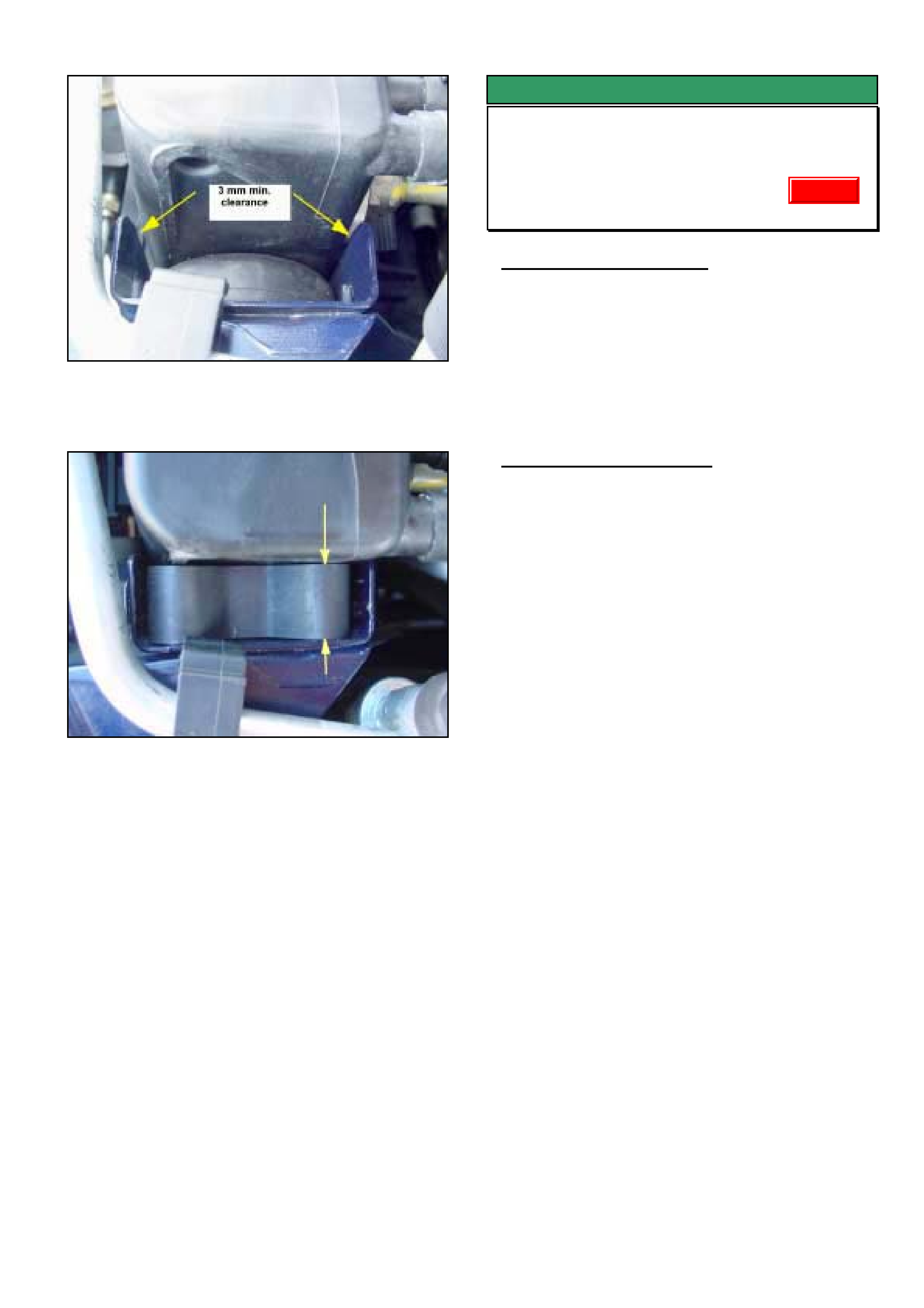
HOLDEN SERVICE TECHLINE_________________________________________________________________ APRIL, 2003
10
Figure 1. Shows potential contact points of radiator
end tanks with body bracket. LHS.
Figure 2. Shows clip making hard contact between
end tank and bracket. LHS.
SERVICE FIX
Park Brake Scrape
VT, VX, VY, VU, V2, WH
(GROUP 5) TL452-0304
PROBLEM DESCRIPTION
Some customers may complain of an intermittent
cyclic scraping noise from the rear of vehicle while
driving. Sometimes the noise appears to go away
after re-applying park brake lever.
The above condition is caused by the secondary park
brake lining (front lining) contacting the drum (in
rotor) without the park brake being applied.
SERVICE RECTIFICATION
Summary: Lubricate park brake shoe contact points
as per following procedure.
Equipment / Materials Required.
• 200 mm vernier caliper capable of reading to
within 0.1mm or better.
• Molybdenum Disulphide grease (Use Shell RD5
or equivalent grease)
• “Brakleen” or similar solvent cleaning product
approved for cleaning brakes.
• Methylated spirits.
Lubricating Procedure (Refer Figure 1.)
1. Remove wheel, caliper and rotor.
2. Check park brake actuation area for gaps in the
following two areas:
Between the adjuster nut and anchor bracket
Between the tappet and anchor bracket
3. If there is a gap, the cable adjustment is too tight
at the park brake lever. Slowly de-adjust cable
until there is no gap.
4. Remove hold-down spring.
5. Remove shoe. If shoe is in good condition then
clean it with Methylated spirits and a rag.
Replace shoe if excessively worn, damaged or
corroded.
6. Hold adjuster nut and tappet in place in the
anchor bracket with rubber band.
7. Spray clean the park brake thoroughly with
'Brakleen' or equivalent.
8. Apply Molybdenum Disulphide grease (Shell RD5
or equivalent) to all six shoe contact points.
The 6 shoe contact points are as follows; 3 points
on the dirt shield, 1 on adjuster nut, 1 on tappet
and 1 on hold-down spring. Hint: If the vehicle is
not brand new, there should be witness marks on
the dirt shield where the shoe has been rubbing.
Grease should be applied to these rubbing
points.
Update
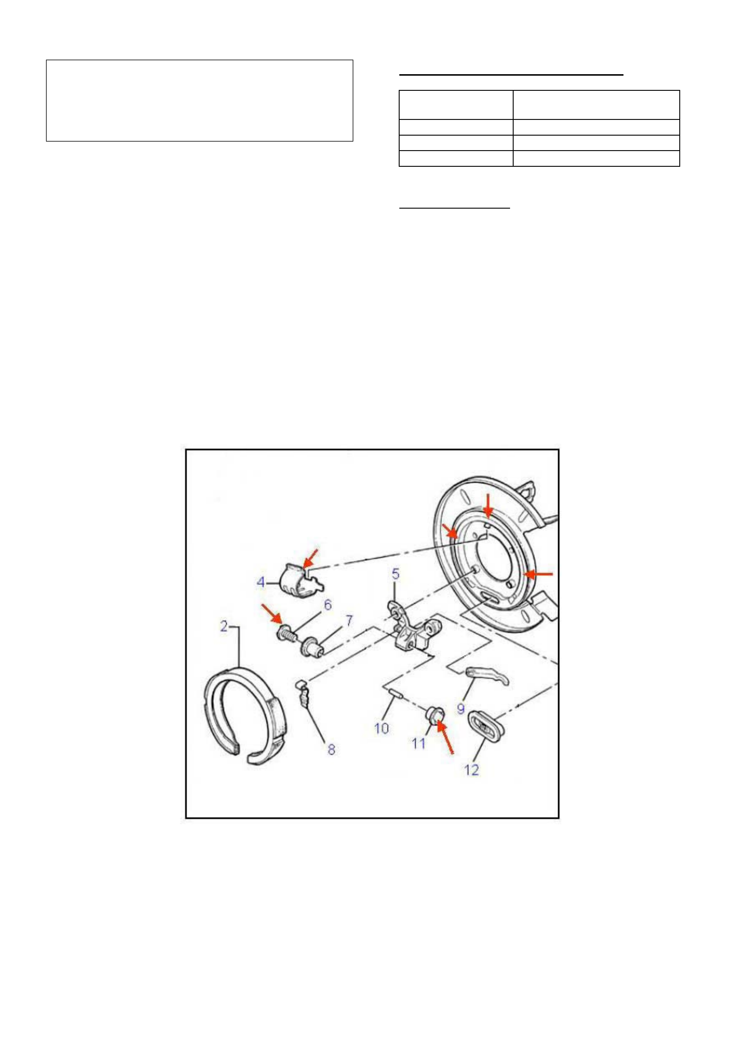
HOLDEN SERVICE TECHLINE_________________________________________________________________ APRIL, 2003
11
IMPORTANT. At no time should grease be allowed
to touch the friction material on the brake shoe
otherwise the shoe must be replaced. It cannot
simply be wiped clean! Please ensure a high level of
cleanliness when handling grease.
9. Remove rubber band holding adjuster nut and
tappet.
10. Re install shoe.
11. Reinstall hold-down spring. (replace if damaged)
12. Set shoe diameter to between 189.5 and 189.7
mm using the adjuster nut. Do not use the cable
at the park brake lever to make this adjustment!.
13. Clean rotor with "Brakleen" or equivalent and
rag.
14. Refit rotor, caliper and wheel.
15. Ensure correct operation of park brake. Adjust
cable if necessary as per service adjustment
procedure.
WARRANTY CLAIM INFORMATION
Description Lubricate park brake shoe
contact points – both sides
Labour Op. No. H000248
Time 1.0 hr
Failure Code 40 noisy
Legend for Figure 1.
2. Park Brake Shoe
4. Brake shoe hold down spring
5. Anchor bracket
6. Brake shoe adjusting screw.
7. Brake shoe adjusting nut
8. Adjuster pawl
9. Brake shoe actuating lever
10. Park brake push rod.
11. brake shoe adjuster tappet
12. Lever to dust shield cover
Figure 1. Grease points (on areas that contact shoe only) shown with arrows
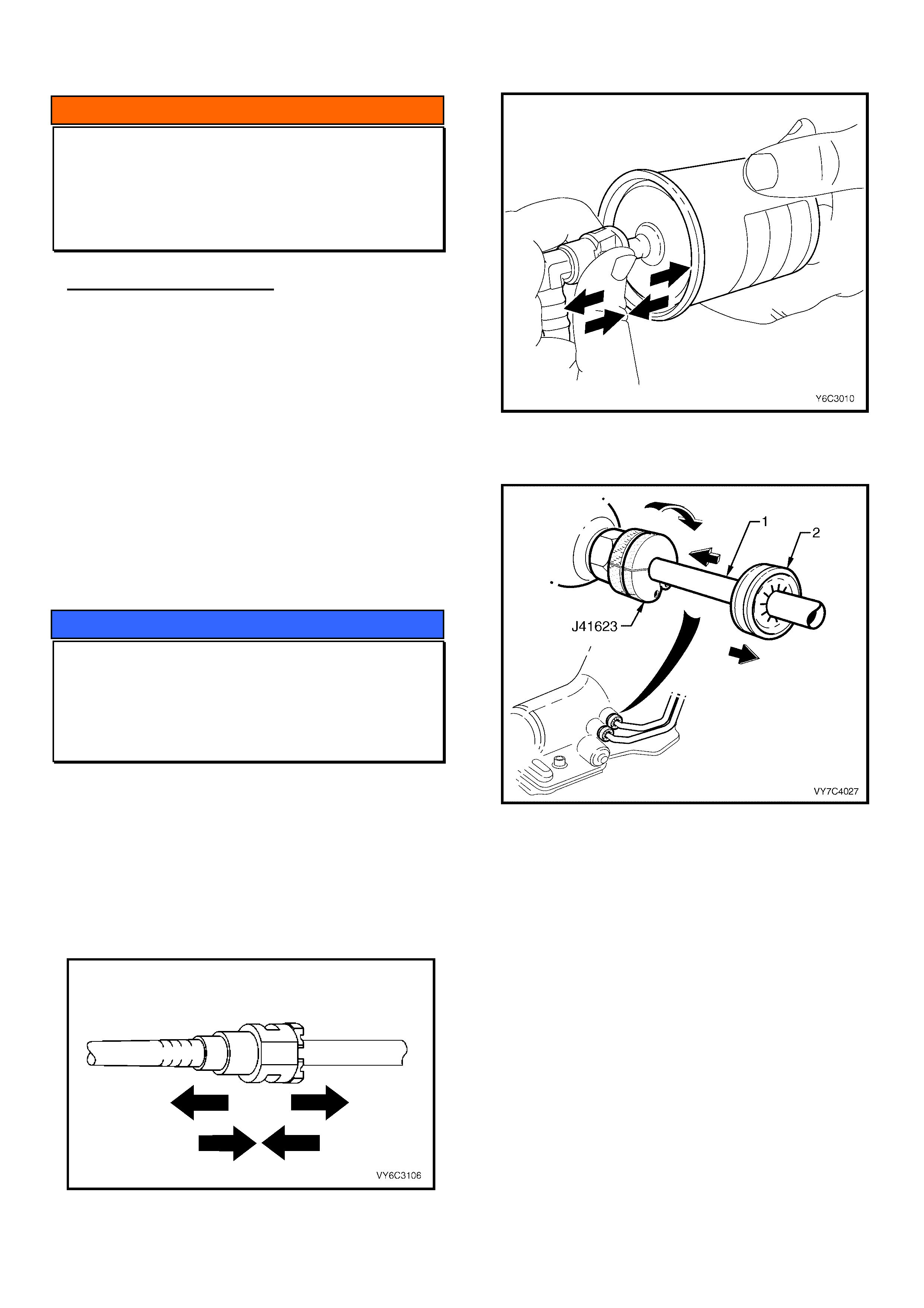
HOLDEN SERVICE TECHLINE_________________________________________________________________ APRIL, 2003
12
INFORMATION
White Marks On Interior Trim
All Models
(GROUP 1) TL468-0304
PROBLEM DESCRIPTION
There have been some dash trims returned to
REPAC that were replaced for exhibiting white stains.
Investigation has found that these stains are in areas
where customer hands are likely to contact the trim.
In all cases the stains were able to be removed using
dish washing liquid diluted with water.
SERVICE PROCEDURE
Quick Connect Fittings
All
(GROUP OB) TL466-0304
The purpose of this techline is to remind technicians
of the importance of always checking quick connect
fittings after reconnection. This is normally done by
pushing/pulling on both sides of the fitting.
Refer to the following drawings from PV SIP which
shows the checking method for some of the different
types of quick connect fittings.
Figure 1. Fuel line fitting (Plastic collar type)
Figure 2. Fuel filter fitting.
Figure 3. 4L60E Auto Trans Cooler lines.
To check A/T cooler pipe quick connect fittings after
reconnection, attempt to pull the pipe free. A 2nd
check is to slide each verifier disc (#2) up to the
fitting. If it engages with the fitting then the pipe has
been correctly installed. NOTE the verifier disc
should be left in this position.
(NOTE; figure 3 shows the quick connect removal
tool J41623 in position)
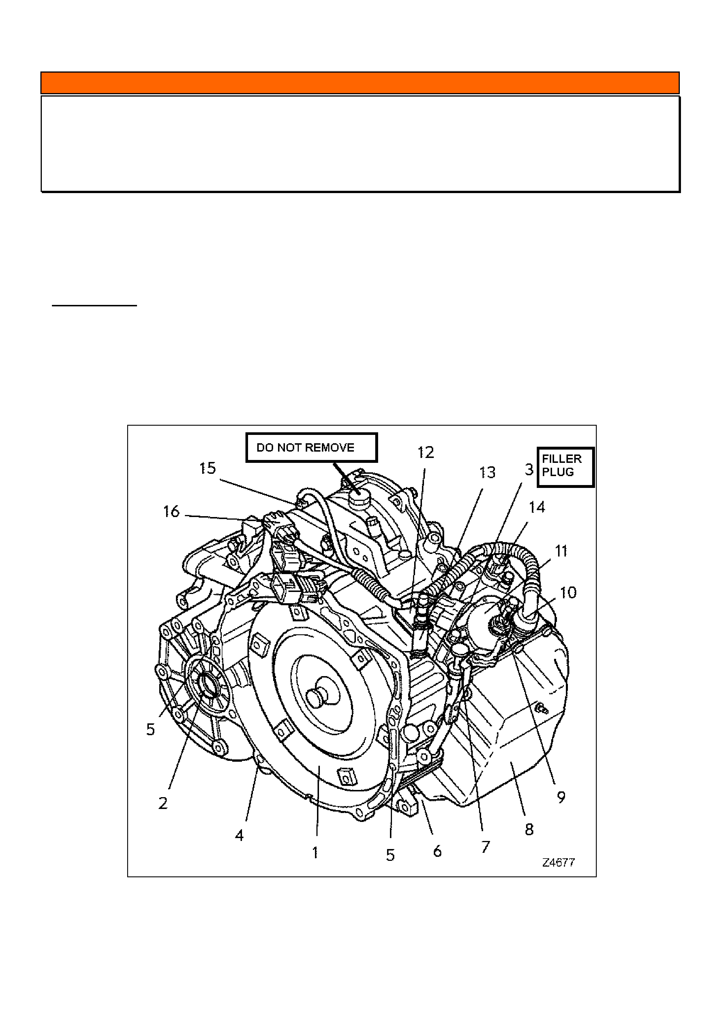
HOLDEN SERVICE TECHLINE_________________________________________________________________ APRIL, 2003
13
INFORMATION
Automatic Transmission Filler Plug Warning
ZC Vectra
(GROUP 7B) TL449-0304
The automatic transmission oil filler plug (internal hex type) is located just next to the transmission switch on top of
the transmission for both the AF23-5 and AF33-5 transmissions. Figure 1, item #3 shows location of the filler plug.
This filler plug must not be confused with the large hex bolt on top of the transmission shown with the “DO NOT
REMOVE” label.
IMPORTANT
DO NOT loosen or remove the large hex bolt on top of the transmission otherwise the
transmission will have to be replaced. This bolt is sealed with white paint up to trans. serial
number 02MV717209. Transmissions after this serial number use a pentagon bolt. Note: This bolt
anchors the B4 band internally in the transmission
Figure 1.

HOLDEN SERVICE TECHLINE_________________________________________________________________ APRIL, 2003
14
INFORMATION
New Body Repair Procedure - MIG Brazing
(Approved Equipment Suppliers)
ZC Vectra
(GROUP 01) TL477-0304
SERVICE INFORMATION
The body panels used on the ZC Vectra utilise a new
range of high tensile steels that must not be welded
during repair using traditional MIG welding. Panels
should only be joined using the MIG brazing repair
procedures outlined in TIS.
If the panels on ZC Vectra are MIG welded, the
composition of the panel metal at the weld will
change, reducing the tensile strength, which
could affect the vehicle performance in durability
and crash performance. Should a MIG weld be
applied the affected panels must be replaced and
then joined using the correct procedure.
MIG Brazing is a low temperature procedure that has
the following advantages:
• Does not alter the composition of the panel
metal.
• Does not remove as much of the panels anti-
corrosive coat.
• Leaves a brazing bead that is more corrosion
resistant
• Lowers distortion to components being joined.
• Allows larger gaps to be filled.
MIG Brazing equipment to Holden’s standards can be
obtained from the following suppliers:
Approved MIG Suppliers
Migatronic
Southern Cross Industrial Supplies P/L
(Includes NZ)
851 Ramsden Drive
Albury NSW 2640
(PO Box 485 Lavington NSW 2641)
Ph: 02 6040 1991
1800 645 587
Fax: 02 6040 1980
Web: www.scws.com.au
Kemppi
Kemppi Australia (Includes NZ)
PO Box 404
2/58 Lancaster Street
Ingleburn NSW 2565
Ph: 02 9605 9500
Fax: 02 9605 5999
Web: www.kemppi.com.au
Fronius
Paul England and Staff
1 Longview Court
Thomastown Vic 3074
Ph: 03 9466 4060
Fax: 03 9464 2106
Web: www.paulengland.com.au
Eutectic New Zealand P/L
Po Box 12559
Unit 0, 20 Sylvia Park Road
Penrose, Auckland
Ph: 95735386
Fax: 95735388

HOLDEN SERVICE TECHLINE___________________________________________________________________ MAY, 2003
6
DIAGNOSIS HINT
Instrument Cluster Lens Replacement
ALL
(GROUP 12) TL497-0305
Holdens Returned Parts Assessment Centre (REPAC)
continues to receive complete instrument cluster
assemblies replaced for complaint of “lens scratched”.
Please note that for most models, replacement lenses
are available from HSPO.
For lens replacement procedure refer to the Service
Instructions in the relevant CD, i.e.
• TIS or
• LCRV SIP or
• PV SIP
WARRANTY CLAIM INFORMATION
For lenses replaced under warranty, use Labour
Times information in Warranty Information section of
current PV SIP CD.
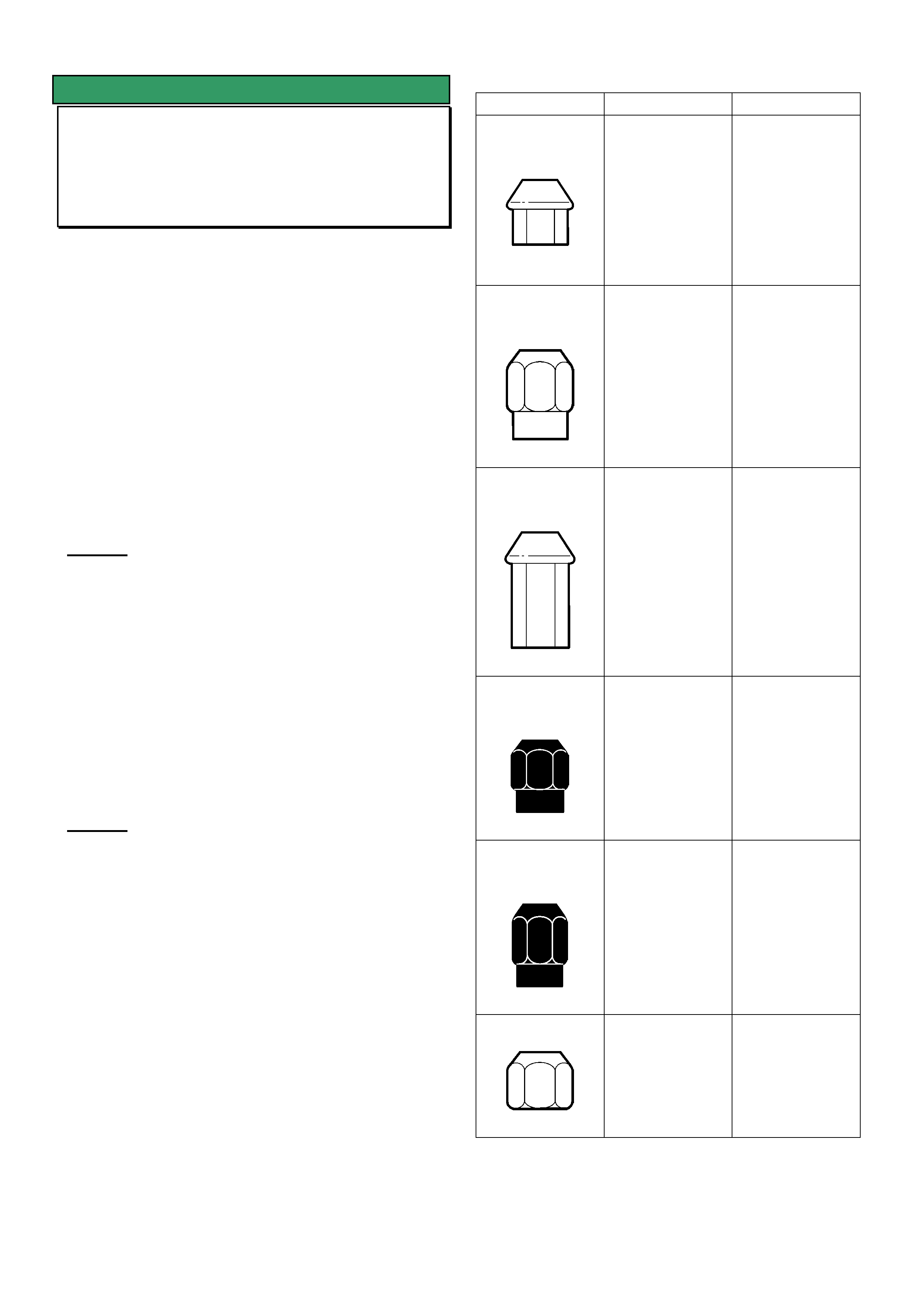
HOLDEN SERVICE TECHLINE___________________________________________________________________ MAY, 2003
7
INFORMATION
Wheel Nut Usage - Alloy & Steel Wheels
All V & W
(GROUP 10) REVISED TL255A-0305
This Techline supercedes the previous one in Issue 3,
April 2002 by revising Note 2 and updating the table.
The purpose of this Techline is to highlight the
importance of only using those wheel nuts that are
specified for the type of wheel fitted to the vehicle.
Originally, alloy wheels had steel nut-seats. However,
in most current design alloy wheels the steel nut-seats
have been deleted and the wheel nuts now bear
directly onto the alloy. The wheel nuts designed for
use on alloy wheels without steel nut-seats have a
much larger taper to provide increased clamping area.
NOTE 1.
Nuts specified for use with steel wheels must not
be used on alloy wheels which do not have steel
nut seats.
If wheel nuts designed for use with steel wheels are
used on alloy wheels without steel nut-seats, there is
potential for the following problems to occur:
1. Lack of sufficient clamp load.
2. Localised nut bite into the alloy nut-seat.
3. Potential fatiguing of the wheel studs.
4. Potential fatigue and/or cracking of the alloy wheel
nut seats.
NOTE 2.
Nuts that are specified for use with alloy wheels
(e.g. 22526184 & 92100089) may in some
circumstances be used on steel wheels. For
example when a vehicle fitted with alloy wheels
has a puncture and a steel spare wheel is fitted
temporarily.
The following table shows many of the nuts specified
in Partfinder® together with the model usage.
Always refer to Partfinder® to determine which nut is
specified for a particular wheel.
Part Number For use on: Models
22526184
Alloy wheels -
without steel nut
seat
May be used
temporarily with
steel wheel.
Refer Note 2.
WK,WH,V2,VY,
VX,VU, VS,VT
92037665
Alloy wheels -
with steel nut
seats.
WH, VT, VS
92100089
Alloy wheel –
without steel nut
seats
May be used
temporarily with
steel wheel.
Refer Note 2.
V2
92045082
Steel wheel only VX,VU,VT,VS,
VP, VR,
92112268
Steel wheel only VY,VX,VU,VT
92015262
Steel wheel only VY,VX,VT,VS,
VP, VR, VQ, VB
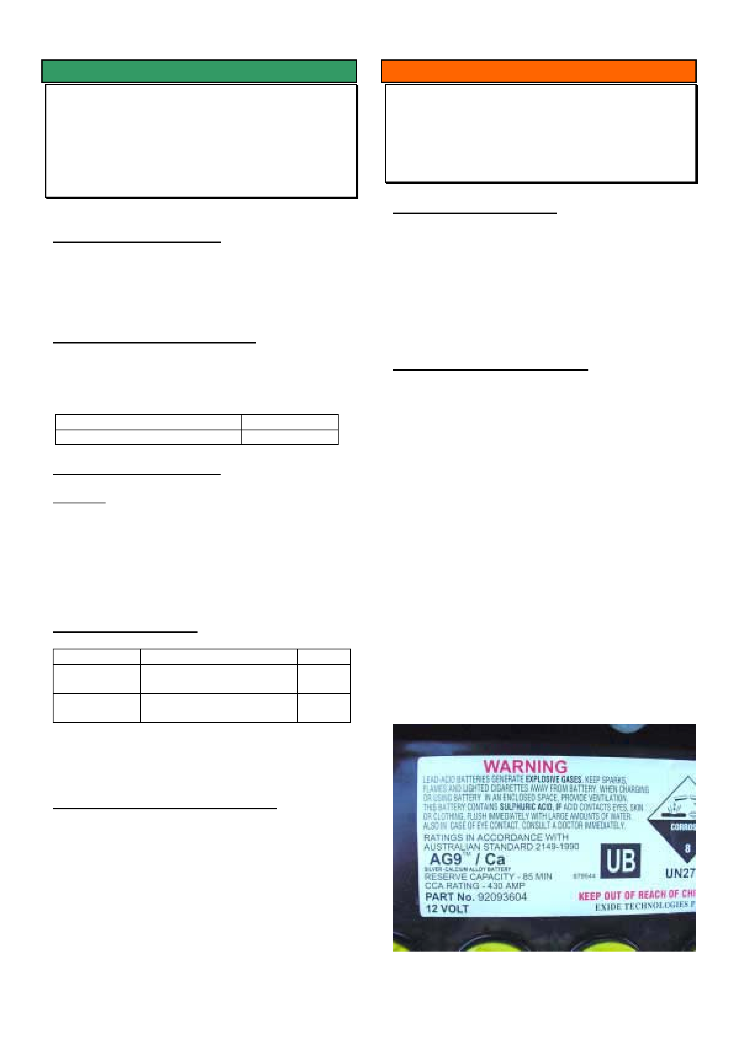
HOLDEN SERVICE TECHLINE___________________________________________________________________ MAY, 2003
8
SERVICE FIX
Roof Joint Moulding Loosens/Detaches
From Roof
VY Ute
(GROUP 01) TL463-0305
PROBLEM DESCRIPTION
The roof joint moulding may become loose and in
some cases detach from vehicle roof. The condition
may be more likely to occur in hot weather.
PRODUCTION RECTIFICATION
To overcome the above condition, roof mouldings
made from revised material have been fitted to
vehicles from:
ISOVIN: Build Date:
6G1YK42F23L102713 02/04/2003
SERVICE RECTIFICATION
Summary: On vehicles built prior to the above
breakpoint where the mouldings have detached from
roof, fit the latest roof mouldings available from
HSPO.
For removal & reinstallation procedures for mouldings
refer to Passenger Vehicle SIP.
PARTS INFORMATION
Part No.: Description: Qty:
92059950 Moulding asm roof panel
joint front finish RH
1
92059951 Moulding asm roof panel
joint front finish LH
1
Note: All the mouldings in HSPO are made from the
latest revised material.
WARRANTY CLAIM INFORMATION
Use Labour Times information in Warranty
Information section of current PV SIP CD
INFORMATION
Battery Replacement During Warranty
VTII / VU / VX / V2 / VY / WH
(GROUP 12) TL482-0305
PROBLEM DESCRIPTION
During Holden’s regular warranty claims analysis it
has been noted that some Retailers are fitting
incorrect batteries to the above listed vehicles.
When replacing any battery under warranty it is
important to ensure that the correctly specified battery
is fitted for the particular vehicle.
SERVICE RECOMMENDATION
The most accurate method of ensuring the correct
battery is fitted is to order it using the part number
specified in Partfinder®.
Early in VT production the battery specification
changed from a Calcium / Calcium battery to a Silver /
Calcium battery.
This change did not affect the Cold Cranking Amps or
the Reserve Capacity but increased the expected
service life.
Through the introduction of silver / calcium alloys in
the production of the positive plates and also a roll
hardening process, the incidence of plate growth and
cracking (which can lead to premature battery failure)
has been dramatically reduced.
Battery material content is generally listed on the label
on top of the battery as follows,
The AG9 represents Silver and the Ca represents
Calcium.
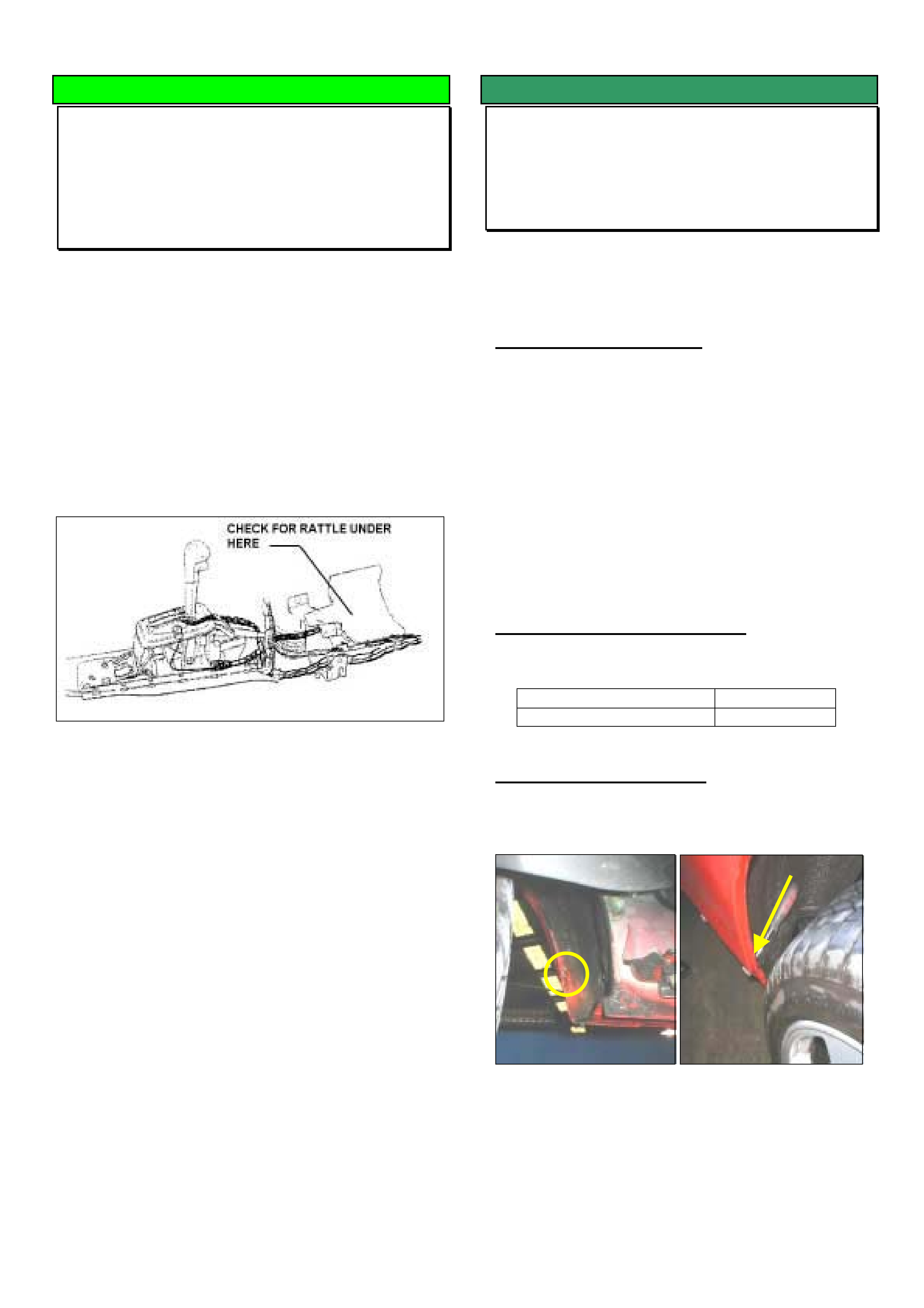
HOLDEN SERVICE TECHLINE___________________________________________________________________ MAY, 2003
9
DIAGNOSIS HINT
Rattle Inside Vehicle (Transmission
Selector Cable)
TS with A/T
(GROUP 7B) TL495-0305
We have received a few isolated reports (PIRs) of a
rattle coming from inside the vehicle which usually
occurs under load, e.g. when lightly accelerating up
hills.
In these cases the transmission selector cable has
been found to be rattling against the Transmission
Control Module located under the centre console.
Technicians report that complaints have been fixed by
wrapping the selector cable with foam in the position
where it rattles.
SERVICE FIX
Water Leak Into Foot Well
V2
(GROUP 1) TL423-0305
Techline Issue 7, 2002 – Page 11 ( V2 Passenger
Side Rocker Panel Water Entry) should be read in
conjunction with this bulletin when completing this
repair.
PROBLEM DESCRIPTION
Water leaks into the foot well/s while driving in heavy
rain.
An unsealed section between two panels in the rear
wheel house allows water and some dirt to enter the
rocker panel. When the volume of water entering
exceeds the capacity of the rocker panel drain holes,
the rocker panel will fill with water and overflow into
the foot well.
The rocker panel moulding could also be applying
pressure to the rocker panel drain plugs preventing
the rocker panel from draining.
PRODUCTION RECTIFICATION
An improved sealing and inspection process has been
introduced from the following ISOVIN:
ISOVIN Date
6G12X14F73L125374 27 May 2003
SERVICE RECTIFICATION
1. Inspect the front of the rear wheel arch to confirm a
gap is present as shown in fig 1.
Figure 1
2. Mark the alignment of the rocker panel drains on
the moulding by placing a small dot near the drain
plugs using a permanent marker.
3. Remove the rocker panel moulding (refer SIP if
required).
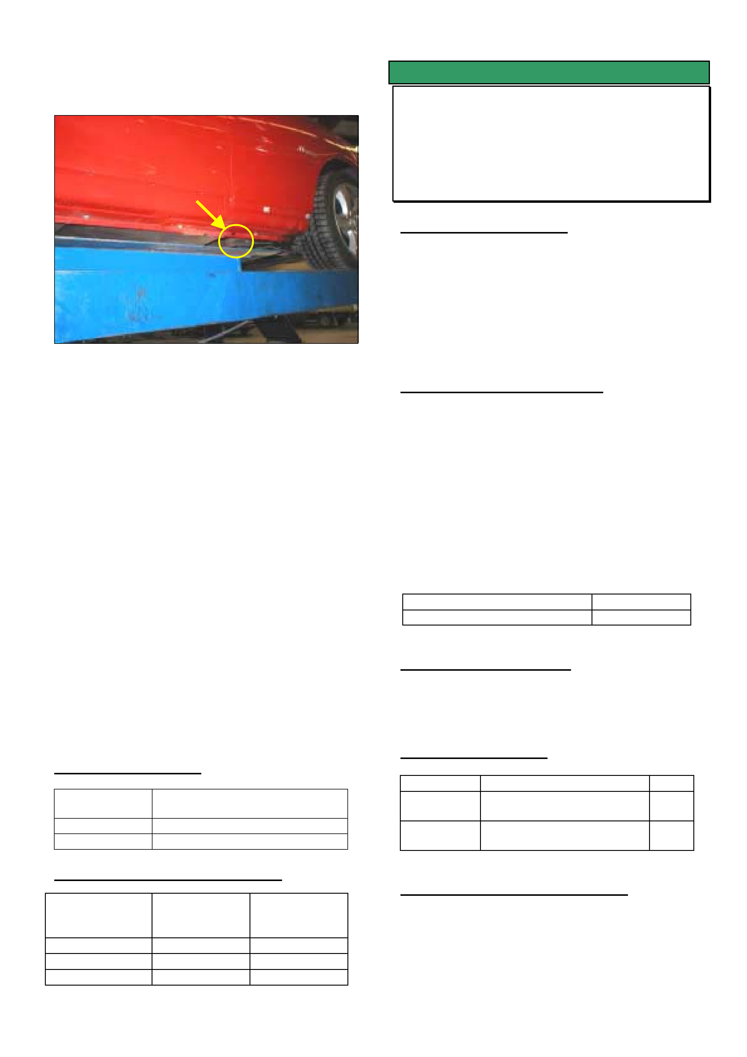
HOLDEN SERVICE TECHLINE___________________________________________________________________ MAY, 2003
10
4. Remove the 4 side drain plugs (Part Number
92036150) and clean any dirt from the rocker panel
drain holes. Refer figure 2.
Fig 2 (there is only one plug shown in this photo)
5. Run water into the gap in the rear wheel house
panels to confirm the leak occurs in this area. This
will also flush any dirt from the rocker panel
preventing further blockage.
6. Check that the drain holes in the rocker panel are
clear.
7. Install four new drain plugs in the rocker panel (do
NOT re-use old plugs).
8. Dry around the gap in the rear wheel house and
seal using Dow Corning 795 grey sealant as
required.
9. File out sufficient material from the rocker
moulding at the previously marked drain locations
to provide clearance and prevent the moulding
from contacting and sealing the drain plug.
10. Refit the rocker panel moulding.
11. Repeat steps 1-8 for the opposite side if a water
leak has been reported on that side. If no water
leak has been reported check for a gap in the
panel sealing as described in Step 1 and seal if
required.
PARTS INFORMATION
Description Plug – Side Door Opening
Frame Hole
Part Number 92036150
Quantity 4 per side
WARRANTY CLAIM INFORMATION
Description Rocker Panel
Water Leaks
- RHS
Rocker Panel
Water Leaks
- LHS
Labour Op. No A000291 A000294
Time 0.6hrs 0.6hrs
Failure Code 87 87
SERVICE FIX
Console Storage Compartment Lid
Broken
VY
(GROUP 1) TL472-0305
PROBLEM DESCRIPTION
Centre console storage compartment door
mechanisms (front and rear) are being broken in
service.
The main cause of breakage is that doors are being
forced open by pulling. The correct opening method
is to push the door and allow the opening mechanism
to function as intended.
PRODUCTION RECTIFICATION
To address the above problem, design changes have
been made which:
(a) reduce finger access to the top edge of the door
and
(b) strengthen the linkage arm pin.
The latest design storage compartment assemblies
can be identified by the rib added below each
mounting hole as shown in drawing below.
Revised storage compartment assemblies have been
fitted to vehicles from:
ISOVIN: Build Date:
6G1YL54A53L973271 11/02/2003
SERVICE RECTIFICATION
On complaint vehicles fit a new storage compartment
assembly of the latest design from HSPO.
PARTS INFORMATION
Part No.: Description: Qty:
92146467 Storage compartment
assembly -Front
1
92109643 Storage compartment
assembly - Rear
1
WARRANTY CLAIM INFORMATION
Use Labour Times information in Warranty
Information section of current PV SIP CD
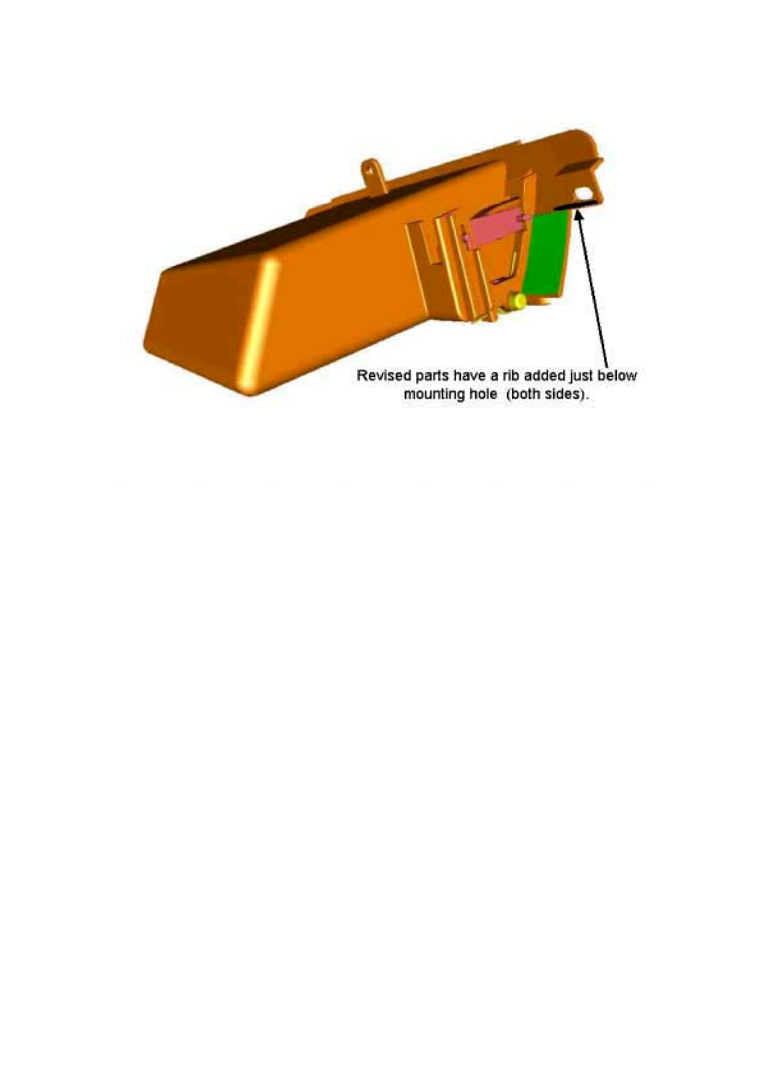
HOLDEN SERVICE TECHLINE___________________________________________________________________ MAY, 2003
11
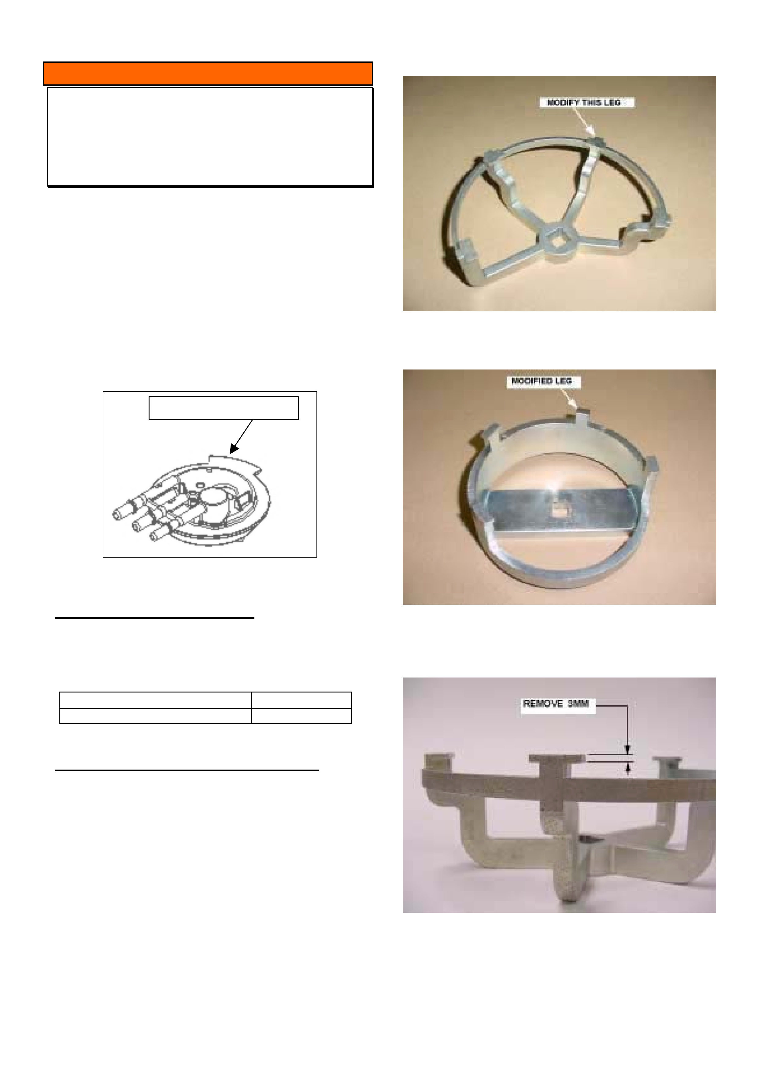
HOLDEN SERVICE TECHLINE___________________________________________________________________ MAY, 2003
12
INFORMATION
MRA Removal Tool Modifications
VT, VX, VY, V2, WH, WK
(GROUP 8) TL490-0305
A design change to the Modular Reservoir Assembly
(MRA) scheduled for production commencement
29/5/03 will necessitate a modification to all existing
MRA service removal tools as detailed below.
The design change involves the addition of a locating
tab to the top of the MRA as shown in Figure 1. This
will provide a consistent orientation of the MRA when it
is installed into the fuel tank.
The design change will be implemented on all body
styles except ute.
LOCATING TAB
Figure 1.
PRODUCTION BREAKPOINTS
A production breakpoint for MRAs with locating tab is
not yet available. Details will be published in the
Breakpoint Summary when they are known.
ISOVIN: Build Date:
TBA TBA
MRA REMOVAL TOOL MODIFICATIONS
There are two versions of the MRA tool. They are part
numbers J39765 and AU 469.
1. Identify which leg requires modification by referring
to Figures 2 and 3.
2. Remove 3mm material (full depth of flange) as
shown in Figure 4 by machining or grinding.
3. Remove any sharp edges or burrs to prevent tool
binding on MRA when in use.
The modified tool is now compatible with MRA's with
and without the additional locating tab and should be
used in accordance with installation and removal
instructions in SIP.
Figure 2. Shows leg to modify on Tool J39765
Figure 3. Shows leg to modify on Tool AU469 (Note:
Photograph shows leg already modified)
Figure 4. Shows amount of metal to be removed.
(Applies to both tools.)
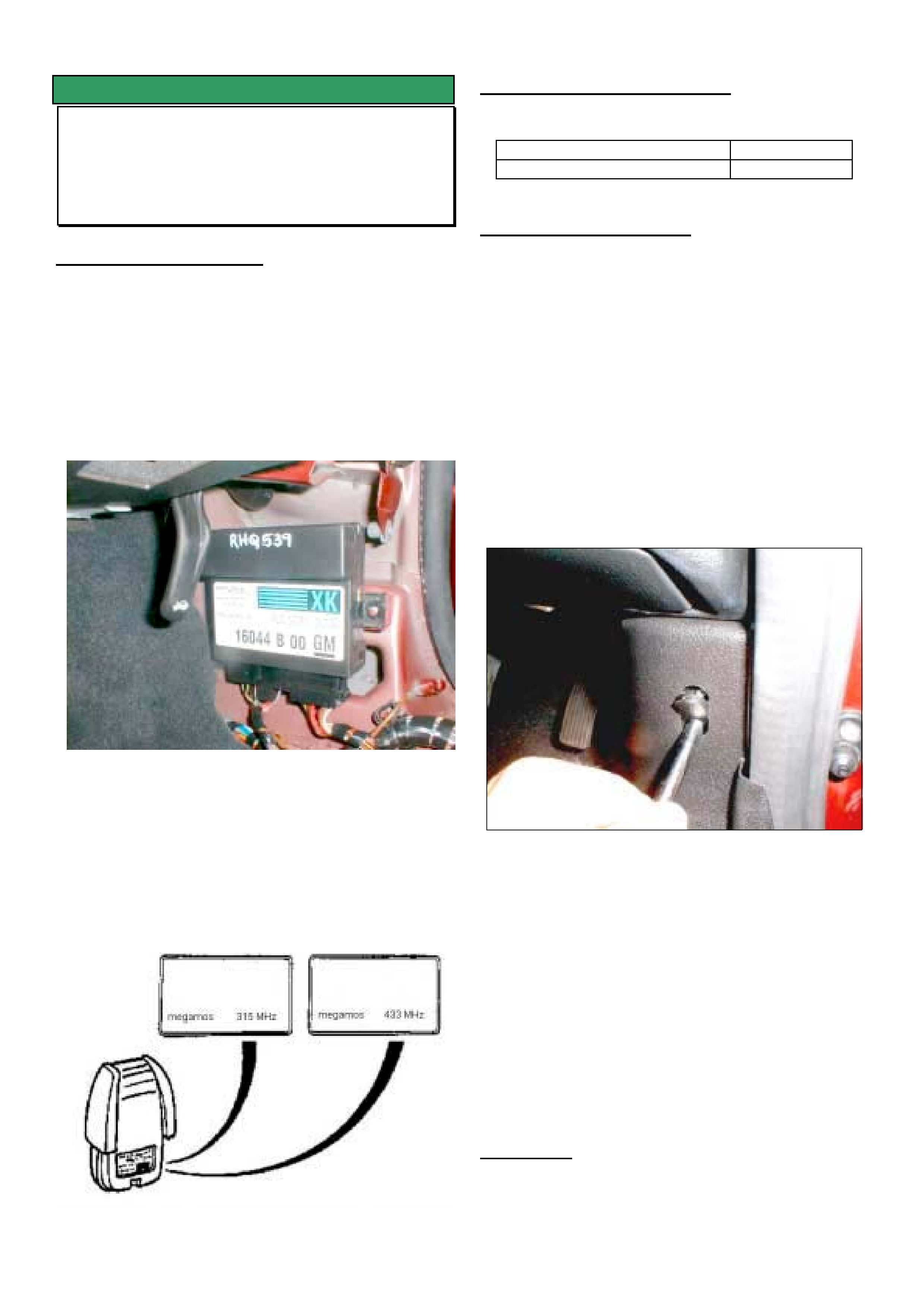
HOLDEN SERVICE TECHLINE___________________________________________________________________ MAY, 2003
13
SERVICE FIX
Central Door Locking - Poor Range
MY02 TS Convertible
(GROUP 12) TL246-0305
PROBLEM DESCRIPTION
Some TS Astra convertible vehicles may experience
poor operating range of the central door locking system
when using the remote sender.
A revised central locking module and remote sender
have been developed to rectify this poor range issue.
The central locking module is located at the bottom of
the right hand “A” pillar as shown in Figure 1.
Figure 1.
The original module used a 315 MHz frequency remote.
The new module uses a 433 MHz remote sender
therefore it is important to ensure the correct remote is
obtained to match the revised module. If the incorrect
frequency remote sender is used, it will not be possible
to program using Tech 2.
The frequency is shown on the remote in following
location.
PRODUCTION RECTIFICATION
433 MHz modules have been fitted to vehicles from:
ISOVIN: Build Date:
W0L0TGF672B009028 31/01/2002
SERVICE RECTIFICATION
Summary: On complaint vehicles built prior to
Production Breakpoint replace 315 MHz Central Locking
Module (& remote) with 433 MHz module (& remote).
Before starting this procedure ensure that you have the
vehicle security code and both customer keys
1. To replace the central locking module, unclip the
front of the right hand side sill cover and remove the
Torx headed screw which secures the lower “A” pillar
cover.
2. Remove the Torx headed screw behind the blanking
plug in the front of the lower “A” pillar cover. Refer
Figure 2.
Figure 2.
3. Once both these screws are removed the cover can
then be removed.
4. This will expose the central locking module which can
be detached from the “A” pillar by removing the two
plastic nuts.
5. Unplug the existing module and install the revised
433 MHz module.
6. Refit the “A” pillar and the sill covers.
7. Program the module and both remotes using Tech 2
updated with software version 10.9 or later.
IMPORTANT: The Central Locking module can only
be programmed once, therefore it is imperative that
the correct information is programmed into the
module.

HOLDEN SERVICE TECHLINE___________________________________________________________________ MAY, 2003
14
The following defines the programming steps using
Tech 2.
Step 1
Step 2
Step 3
Step 4
Step 5
Step 6
Step 7
OR
Step 8
Step 9
Main Menu
F0: Diagnostics
F1: Service Programming System (SPS)
F2: View Capture Data
F3: Tool Options
F4: Download / Upload Help
Vehicle Identification
Select one of the following
Model Year(s)
(2) 2002
(1) 2001
(Y) 2000
(X) 1999
(W) 1998
(V) 1997
Vehicle Identification
Select one of the following
Vehicle Type(s)
VX Commodore
VU Utility
WH Statesman & Caprice
VT Commodore
Corsa-B
Corsa-C
Astra-F
Astra-G
System Selection Menu
(2) 2002 Astra - G
F0: Engine
F1: Transmission
F2: Chassis
F3: Body
Vehicle Identification
Select one of the following
Body
Immobiliser
Airbag
Instrument
Engine Cooling Module
Add On Heater
Electronic Climate Control
Central Door Lock
Anti Theft Warning
Triple Info Display
Body
(2) 2002 Astra - G
Anti Theft Warning
Turn On Ignition
Confirm
Body
F0: Diagnostic Trouble Codes
F1: Data Display
F2: Snapshot
F3: Actuator Test
F4: Programming
Programming
F0: Erase Remote Keys
F1: Program Remote Keys
F2: Program Anti Theft
F3: Program Country Code
F4: Program Central Door Lock. System
Body
(2) 2002 Astra - G
Anti Theft Warning
Partnumber 13515B00
Identifier B0
Confirm
More
Body
(2) 2002 Astra - G
Anti Theft Warning
Partnumber 17157B00
Identifier B1
Confirm
More
HOLDEN SERVICE TECHLINE___________________________________________________________________ MAY, 2003
15
Step 10
Step 11
Step 12
Step 13
Step 14
Step 15
Step 16
Step 17
OR
Step 18
Your
vehicle
security
code
Program Central Door Lock. System
(2) 2002 Astra – G
Anti Theft Warning
Enter Security Code !
0000
Press ENTER key to continue
Program Central Door Lock. System
(2) 2002 Astra – G
Anti Theft Warning
Enter Security Code !
0000
Not Okay Okay
Program Central Door Lock. System
(2) 2002 Astra – G
Anti Theft Warning
Programming Active Please Wait !
Vehicle Identification
Select one of the following
Body
Immobiliser
Airbag
Instrument
Engine Cooling Module
Add On Heater
Electronic Climate Control
Central Door Lock
Anti Theft Warning
Triple Info Display
Programming
(2) 2002 Astra – G
Central Door Lock
Turn On Ignition !
Confirm
Your
vehicle
security
code
Program Central Door Lock. System
(2) 2002 Astra – G
Anti Theft Warning
Central Door Locking System
Programming Completed !
Confirm
Program Central Door Lock. System
(2) 2002 Astra – G
Anti Theft Warning
Please Reselect System !
Confirm
Body
F0: Diagnostic Trouble Codes
F1: Data Display
F2: Snapshot
F3: Actuator Test
F4: Programming
Programming
(2) 2002 Astra - G
Central Door Lock
Part number 13515B00
Identifier
BA
Confirm
Programming
(2) 2002 Astra - G
Central Door Lock
Part number 17157B00
Identifier
BB
Confirm
HOLDEN SERVICE TECHLINE___________________________________________________________________ MAY, 2003
16
Step 19
Step 20
Step 21
Step 22
Step 23
Step 24
Step 25
Step 26
When you have finished programming, exit out of Tech 2
screens and disconnect the Tech 2.
Test the operation of both remote keys!!!
PARTS INFORMATION
The following parts have previously only been available
from TAS. They can now be purchased from HSPO.
Part No.: Description: Qty:
93174750 Central locking module
(433MHz)
1
09153235 Remote Sender
(433MHz)
2
WARRANTY CLAIM INFORMATION
Description R&R Central Door Locking
module(433MHz)
Labour Op.No. N000372
Time 0.6 hr
Failure Code 33
Program Remote Key
(2) 2002 Astra – G
Central Door Lock
Enter Security Code !
0000
Press ENTER key to continue
Program Remote Key
(2) 2002 Astra – G
Central Door Lock
Hold Remote Key To The Receiver And
Activate Several Times !
Your
vehicle
security
code
Programming
F0: Erase Remote Keys
F1: Program Remote Keys
F2: Program Anti Theft
Program Remote Key
(2) 2002 Astra – G
Central Door Lock
Enter Security Code !
0000
Not Okay Okay
Your
vehicle
security
code
Program Remote Key
(2) 2002 Astra – G
Central Door Lock
Do you want to Program the next remote
key?
NO Yes
Program Remote Key
(2) 2002 Astra – G
Central Door Lock
Remote Key Successfully Programmed !
Confirm
Program Remote Key
(2) 2002 Astra – G
Central Door Lock
Hold Remote Key To The Receiver And
Activate Several Times !
Program Remote Key
(2) 2002 Astra – G
Central Door Lock
Remote Key Successfully Programmed !
Confirm
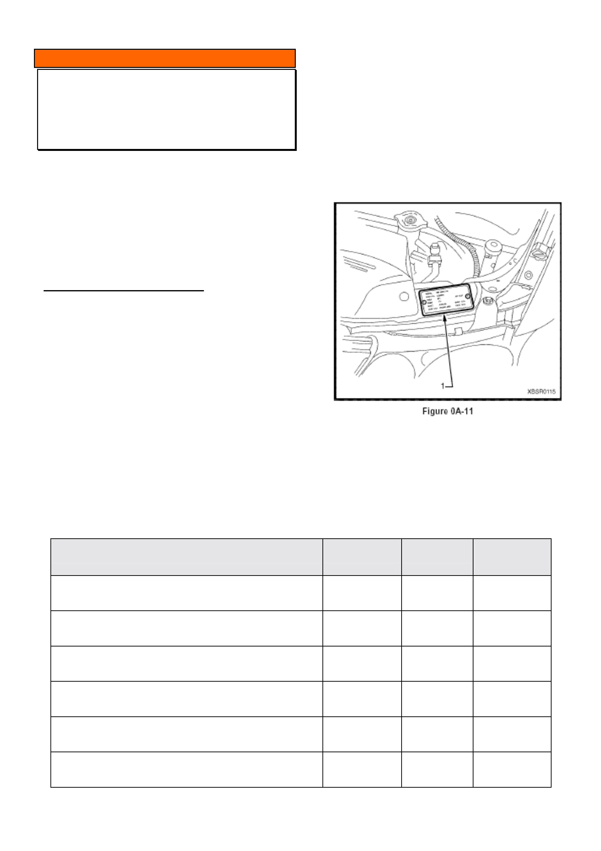
HOLDEN SERVICE TECHLINE___________________________________________________________________ MAY, 2003
17
INFORMATION
New Entertainment System Code Index
VY, V2 Series II
(GROUP 12) TL450A-0303
This Techline supercedes the previous one in Issue 3,
Mar, 2003. It is revised by adding Calais, CV8 and all
HSV to the table.
-----------------------------------------------------------------
Due to a running change of components within the VY
and V2 Series II Blaupunkt Entertainment system it
has been necessary to add some additional code
indexes.
SERVICE RECOMMENDATION
When installing an upgrade or warranty replacement
radio, it is necessary to program the code index within
the unit to configure it to the particular vehicle.
To program the code index refer to PV SIP
Section 12D / Entertainment System / 3.11 Program /
F0: Program Code Index.
Use the following table to obtain the correct code
index.
• If the code index in the replacement radio is
between 001 and 006 use column A,
• If the code index in the replacement radio is
between 007 and 012 use column B, in the table
below.
Note: The vehicle description 8VK or 8VL refers to its
luxury level and is found on the Body and Option plate
which is located on the radiator support panel as can
be seen below.
Vehicle
CD unit
Code Index A
Code Index B
All 8VK (Executive, Acclaim, SS, CV6 etc) Except 8VK80
Single
001
007
All 8VK (Executive, Acclaim, SS, CV6 etc) Except 8VK80
6 Stack
001
007
All 8VL (Berlina)
6 Stack
001
007
8VK80 & 8VK03 (Ute / Cab Chassis)
Single
003
009
8VK80 & 8VK03 (Ute / Cab Chassis)
6 Stack
003
009
8VX (Calais / CV8) and All HSV
6 Stack
004
010
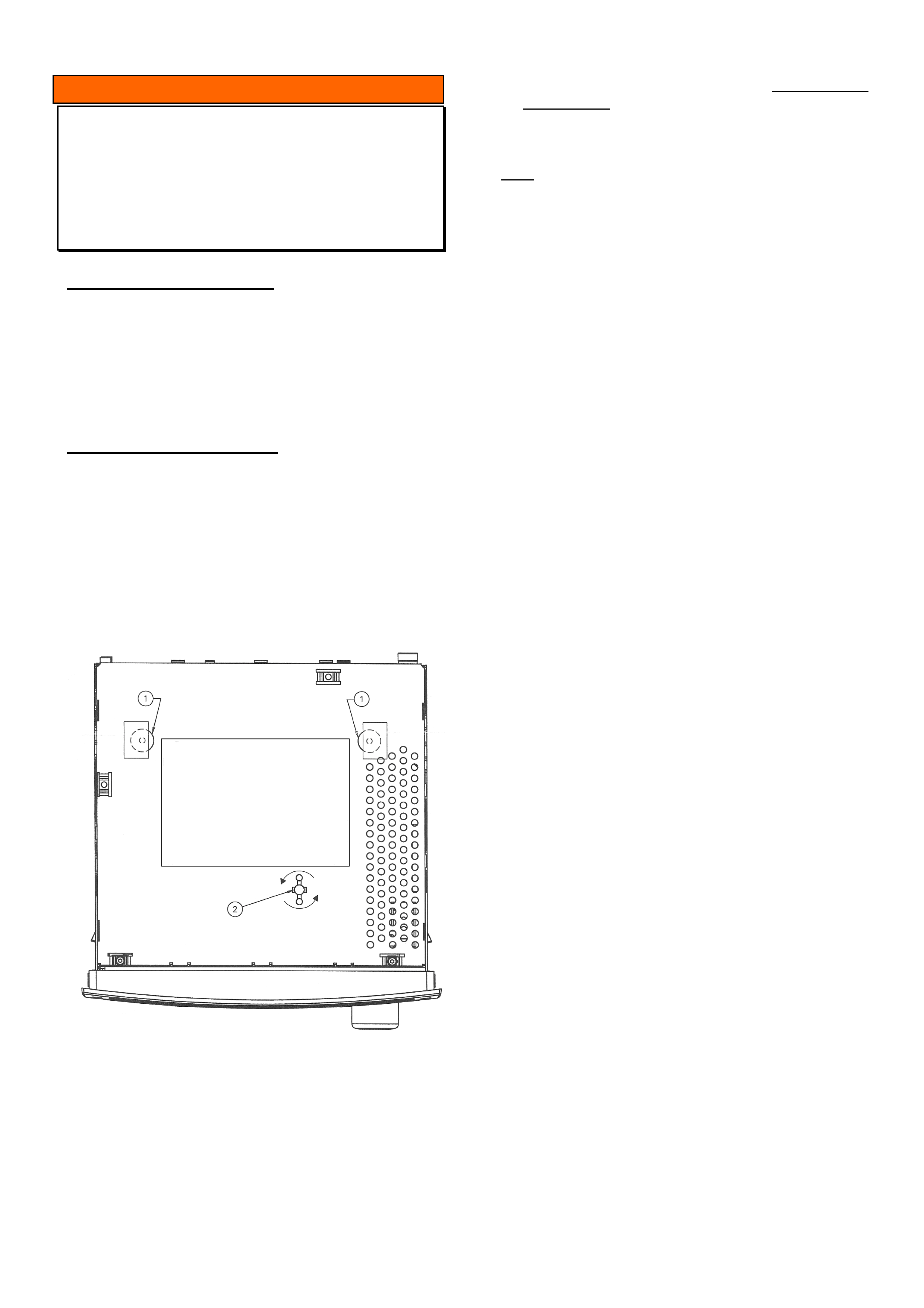
HOLDEN SERVICE TECHLINE___________________________________________________________________ MAY, 2003
18
INFORMATION
Blaupunkt Audio Head Unit Displays
“MECH ERROR” and Won’t Accept CD’s
VY / V2II / WK (Six stack CD only)
(GROUP12) TL480-0305
PROBLEM DESCRIPTION
There have been several reports of Blaupunkt six
stack audio head units not accepting CD’s and LCD
display showing “MECH ERROR”.
The cause of this problem is that the transportation
locking pins have not been removed from the unit.
SERVICE RECTIFICATION
At PDI or after an exchange audio head unit has
been fitted, if it’s discovered that the unit will not
accept CD’s or the LCD displays shows “MECH
ERROR” perform the following operation.
Remove the audio head unit from the vehicle and
inspect the top panel to ensure that the three
transportation locking pins have been removed as
per the diagram below.
If transportation pins are found to be present perform
the following steps,
1. Remove the tape from location #1 (2 places) then
remove both rubber spacers.
2. Rotate transportation pin in location #2 counter
clockwise then remove from the unit.
3. If no transportation pins are present and the unit is
still faulting contact Blaupunkt on 1300 707 036
for diagnosis assistance.
Note: Even if the transportation pin in location #2 is
not obvious, look into the hole to ensure that it has
not been broken off. If the pin has been broken off
and is unable to be removed request a Change Over
unit from Blaupunkt (refer to DL 08/03 or the change
Over section in SIP).
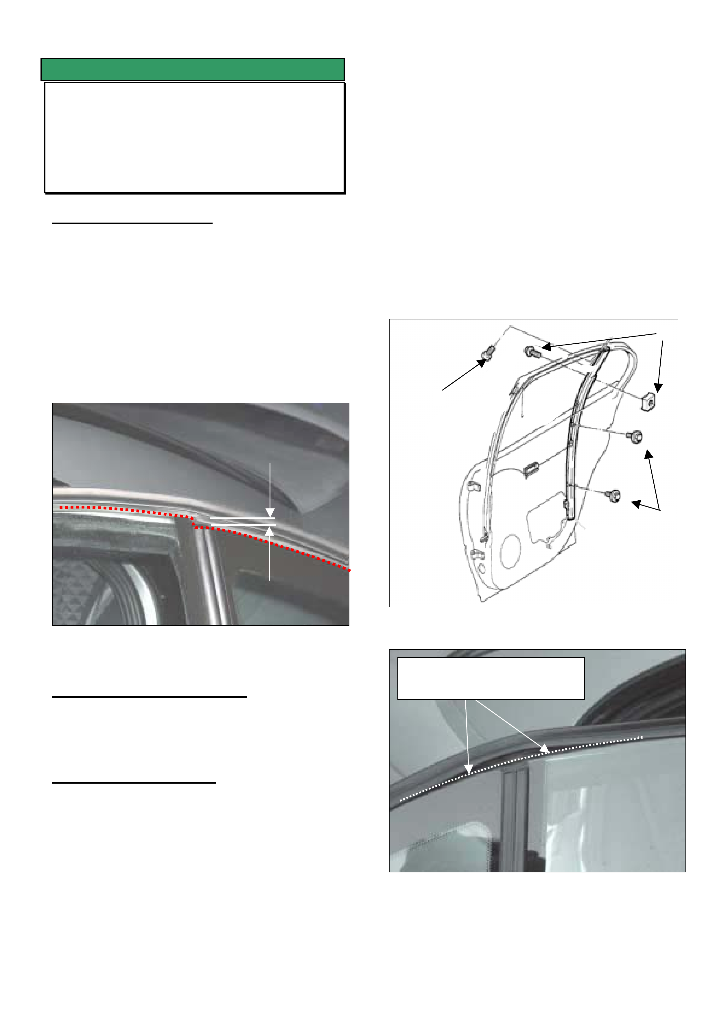
HOLDEN SERVICE TECHLINE___________________________________________________________________ MAY, 2003
19
SERVICE FIX
Rear Door Hard To Close, Water Leak Or
Seal Alignment
VY SEDAN AND WAGON
(GROUP 1) TL484-0305
PROBLEM DESCRIPTION
The rear door glass currently has one stop in the
front channel to stop the glass at the end of its run.
This allows the rear of the glass to over travel
deforming the door frame weather seal. Figure 1
shows the over- travel condition.
This condition can cause high closing effort for the
rear doors, water leaks and poor appearance.
Vehicles fitted with electric windows are more likely to
be affected due to the higher closing force of the
window.
Figure 1. Lift weather seal to inspect glass
alignment.
PRODUCTION RECTIFICATION
The rear run channel will be lanced to form a stop.
The Breakpoint is yet to be achieved and will be
advised when available.
SERVICE RECTIFICATION
Summary: On complaint vehicles install a window
stop to the rear door rear channel as per following
procedure.
1. Move the window to the lowest position.
2. Remove the door trim (refer SIP procedure).
3. Loosen the screws (#1) shown in Fig. 2.
4. Remove screw (#3) shown in Figure 2.
5. Work the top of the channel toward the centre of
the door so the stop can be installed as shown at
position 3 in Figure 2.
6. Re-secure the rear run channel.
7. Adjust the stop so the window stops level with the
rear fixed glass as shown in Figure 3.
8. Torque the adjusting screw to 1-2Nm and confirm
the correct stopping position has been achieved.
9. Confirm that original complaint has been
corrected.
10. Reinstall the interior door trim (the plastic shield
must be correctly installed and sealed).
Figure 2
Figure 3. Lift weather seal to inspect glass
alignment.
1
2
3
Rear fixed glass and window
glass must follow the same line

HOLDEN SERVICE TECHLINE___________________________________________________________________ MAY, 2003
20
PARTS INFORMATION
Part No.: Description: Qty:
90224863 Nut – Window Glass
Stop
1
92138330 Screw – Window
Glass Stop
1
WARRANTY CLAIM INFORMATION
Description Rear Window Stop - LHS
Labour Op. No. C000488
Time 0.5 hr
Failure Code 25
Description Rear Window Stop - RHS
Labour Op. No. C000485
Time 0.5 hr
Failure Code 25
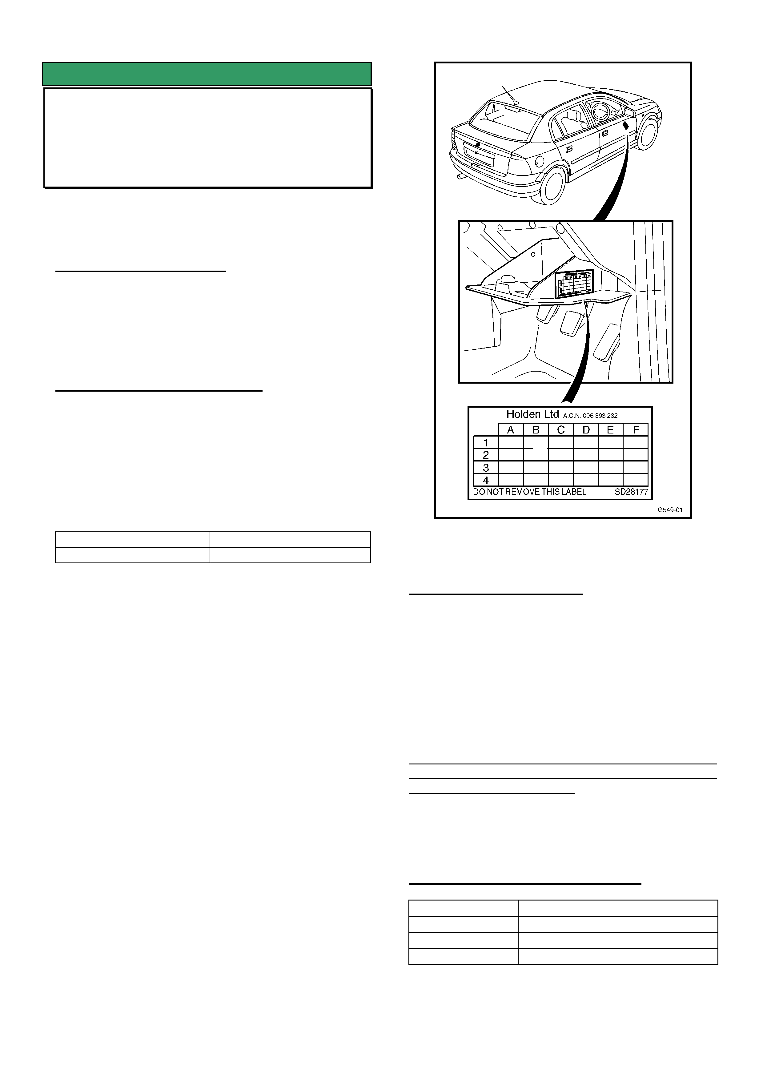
HOLDEN SERVICE TECHLINE________________________________________________________________ JUNE, 2003
6
SERVICE FIX
DTC P0335 sets, CEL Illuminates
TS with Z18XE engine
(GROUP 6C) TL209A-0306
This Techline supercedes the previous one in Issue 1,
Feb, 2002. For all cases of DTC P0335 follow the
procedure in this updated techline.
PROBLEM DESCRIPTION
Engine DTC P0335 sets unecessarily. CEL (Check
Engine Light) on dash illuminates.
Investigations show this condition is caused by an
engine software calibration issue.
PRODUCTION RECTIFICATION
Initial rectification is being done at Port Of Entry. Final
rectification will be done at the Vehicle Assembly Plant
.
1. Port Of Entry.
A revised engine calibration has been reprogrammed
into vehicles at Port of Entry (POE) commencing from:
ISOVIN Date
- 6th June 2003
Vehicles with revised software can be identified by an
“X” in the B1 co-ordinate of the Service History Label
as per Figure 1.
2. Vehicle Assembly Plant
A breakpoint for introduction of the revised engine
calibration into vehicle production will be given in a
future Techline Breakpoint Summary.
FIGURE 1.
SERVICE RECTIFICATION
Summary: Reprogram ECU with TIS CD 42.0 or later.
1. On complaint vehicles, ensure that the ECU has
not already been programmed at Port Of Entry as
shown by a mark in the B1 co-ordinate of the
Service History Label.
2. Reprogram the ECU with revised software from
TIS 2000 CD 42.0 (Tech 2 software version 12.2).
IMPORTANT: If Tech 2 software version 12.2 is not
loaded, then Tech 2 will be unable to communicate
with the reprogrammed ECU.
3. Apply a Service History Label (SD-28177) to the
fuse panel cover as shown in Figure 1 and mark
the B1 co-ordinate of the label.
WARRANTY CLAIM INFORMATION
Description Reprogram ECU - DTC P0335
Labour Op. No. J000707
Time 0.4 hr
Failure Code 57 Registers incorrectly
X
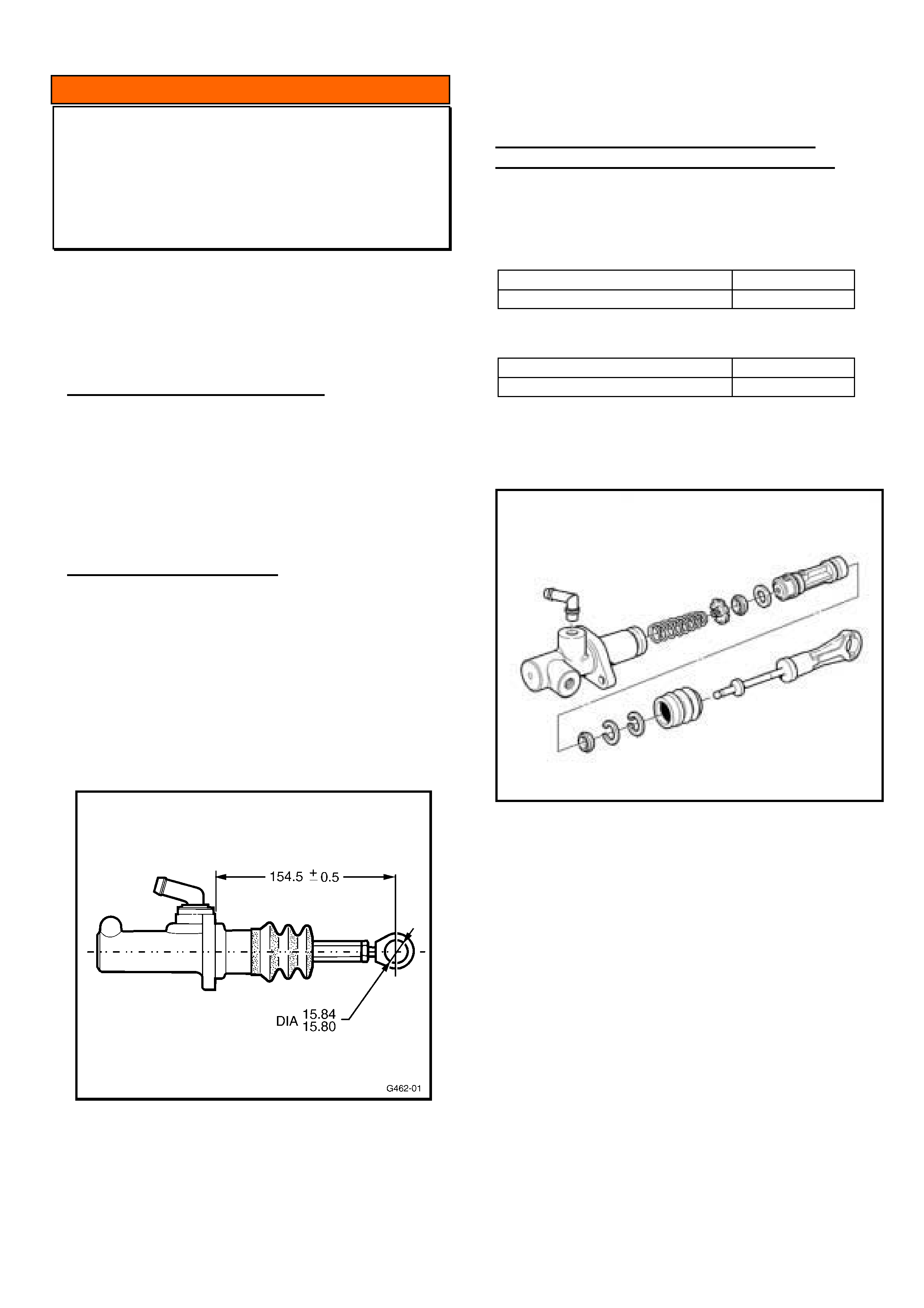
HOLDEN SERVICE TECHLINE________________________________________________________________ JUNE, 2003
7
INFORMATION
Clutch Master Cylinders with Adjustable
Pushrods - Precaution
VT, VX, VU, MY 2002 V2 – All with M/T
(GROUP 7A) Revised TL510-0306
This Techline supersedes the previous one in Issue 2,
February, 2001. It is revised by adding VX & V2 to
models, and breakpoint information on introduction of
non-adjustable pushrods.
SERVICE RECOMMENDATIONS
The clutch master cylinder adjustable type pushrod
should NOT be adjusted in any way.
The pushrod length is pre-set in master cylinder
production.
This dimension must remain unchanged to assure
correct clutch hydraulic system operation.
SERVICE RECTIFICATION
As there is a possibility that technicians may attempt
to adjust this pushrod length, the following Figure 1.
with correct setting dimension is provided only for
purpose of resetting.
Setting this dimension will require master cylinder
removal.
The dimension provided is specifically for VT, VX, MY
2002 V2 & VU models.
Figure 1.
The following information is provided for reference
only:
INTRODUCTION OF NON ADJUSTABLE
CLUTCH MASTER CYLINDER PUSHRODS
Non-adjustable master cylinder pushrods were fitted
to vehicles from:
VX, VU with V6:
Tag No.: Build Date:
L867739 18/05/02
VX, VU with V8:
Tag No.: Build Date:
L867195 18/05/02
V2: All from 2003 Model Year.
VY: All
Figure 2. Clutch Master Cylinder with Non adjustable
Push rod.
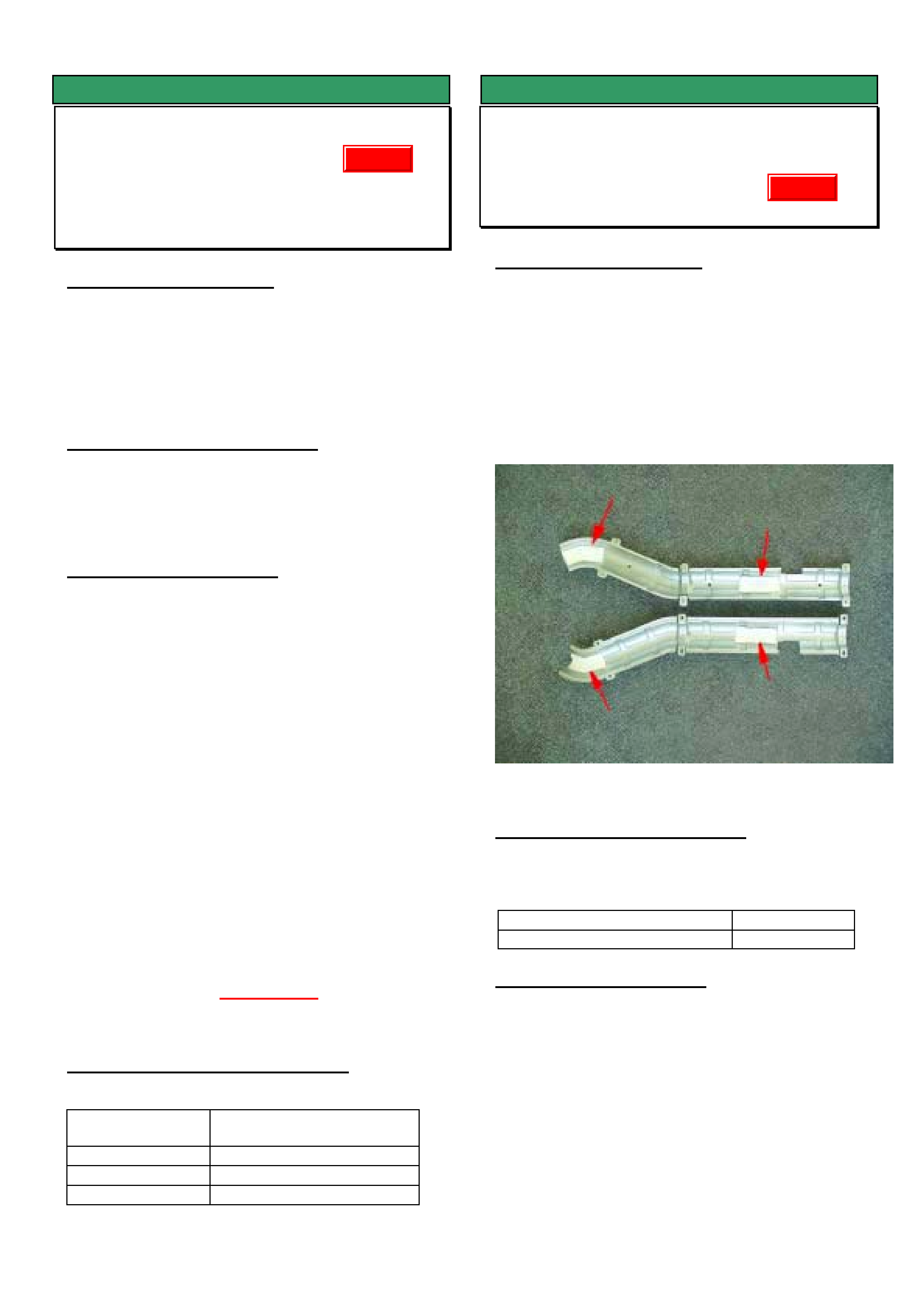
HOLDEN SERVICE TECHLINE________________________________________________________________ JUNE, 2003
8
SERVICE FIX
Gear Lever Rattle Caused By Remote
Shifter Linkage
VTII, VX, VU, VY, V2 with Gen III M/T
(GROUP 7A) TL464-0306
PROBLEM DESCRIPTION
On some vehicles under certain driving conditions the
gear shift lever may rattle. This condition must not be
confused with a gear knob rattle/buzz which may
occur on some vehicles.
The cause of the rattle can be due to excessive
clearances in the remote shifter linkage mechanism.
PRODUCTION RECTIFICATION
Revised remote shifter assemblies to eliminate rattle
are planned for production around September 2003
timeframe. Breakpoint details will be provided at that
time.
SERVICE RECTIFICATION
As mentioned above, revised remote shifter
assemblies will not be available from the supplier until
around Sep. 2003. In the interim, Holden Service
Engineering has arranged the supply of revised shifter
assemblies which have been precision machined and
fitted with anti-rattle washers. These revised shifters
are available via an exchange program run by TAS.
Exchange Program Procedure.
1. To obtain a revised shifter assembly have your
nominated TAS contact person ring TAS to register
a case.
2. TAS will contact you when a revised shifter is
available and they will arrange to have it freighted
to your Retailership.
3. Retailer can then make a firm customer booking to
install the revised shifter.
4. Return the replaced shifter using the REPAC
return process, immediately the shifter is
removed.
Do not wait for the next REPAC report!
WARRANTY CLAIM INFORMATION
For vehicles repaired under warranty :
Description Replace transmission
remote shifter assembly
Labour Op. No. K000291
Time 2.7 hr
Failure Code 28 rattle
SERVICE FIX
Front Exhaust Pipe Heat Shield Vibrates
WK with Gen III
(GROUP 8) TL514-0306
PROBLEM DESCRIPTION
A buzz/vibration from front exhaust pipe heat shields
which occurs on takeoff under light loads such as
driving uphill.
For shield location refer to Figure 2, item 4.
The cause of the buzz has been traced to loose
insulation pads which are normally located as shown
in Figure 1. On complaint vehicles these pads may
become dislodged.
Figure 1. Location of insulator pads
PRODUCTION RECTIFICATION
Exhaust heat shields with revised adhesive for
attaching insulators have been fitted to vehicles from:
ISOVIN: Build Date:
6G1KY54F74L119610 12/5/03
SERVICE RECTIFICATION
Complaint vehicles can be rectified by fitting new heat
shields which are currently only available through
TAS.
To obtain new heat shields register a case with TAS
who will then arrange for shields to be forwarded to
your Retailership.
Update
Update
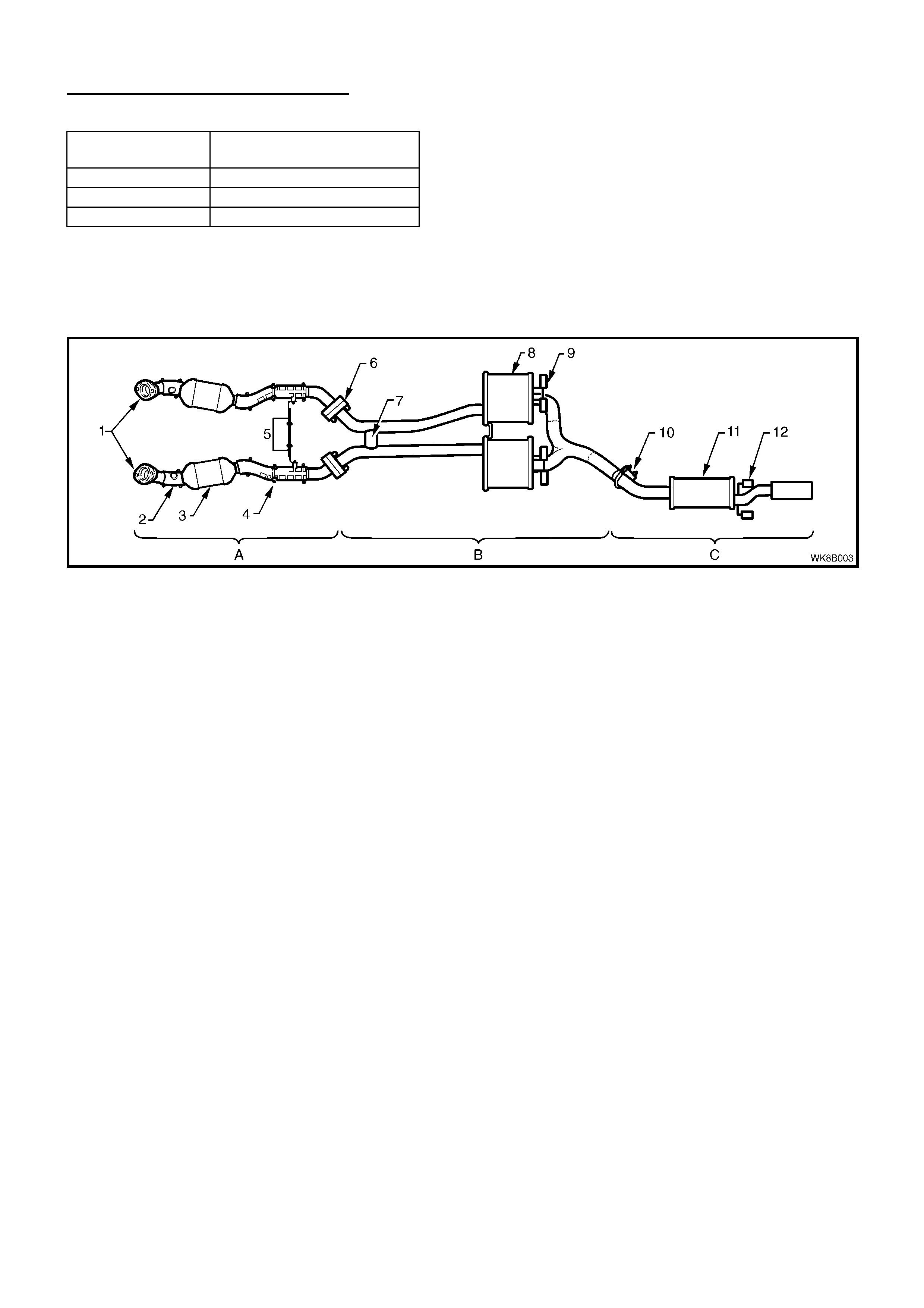
HOLDEN SERVICE TECHLINE________________________________________________________________ JUNE, 2003
9
WARRANTY CLAIM INFORMATION
Description Replace front exhaust
heat shields
Labour Op. No. L000217
Time 0.5 hr
Failure Code 36 vibration
Figure 2. Item 4 = post catalytic converter heat shields
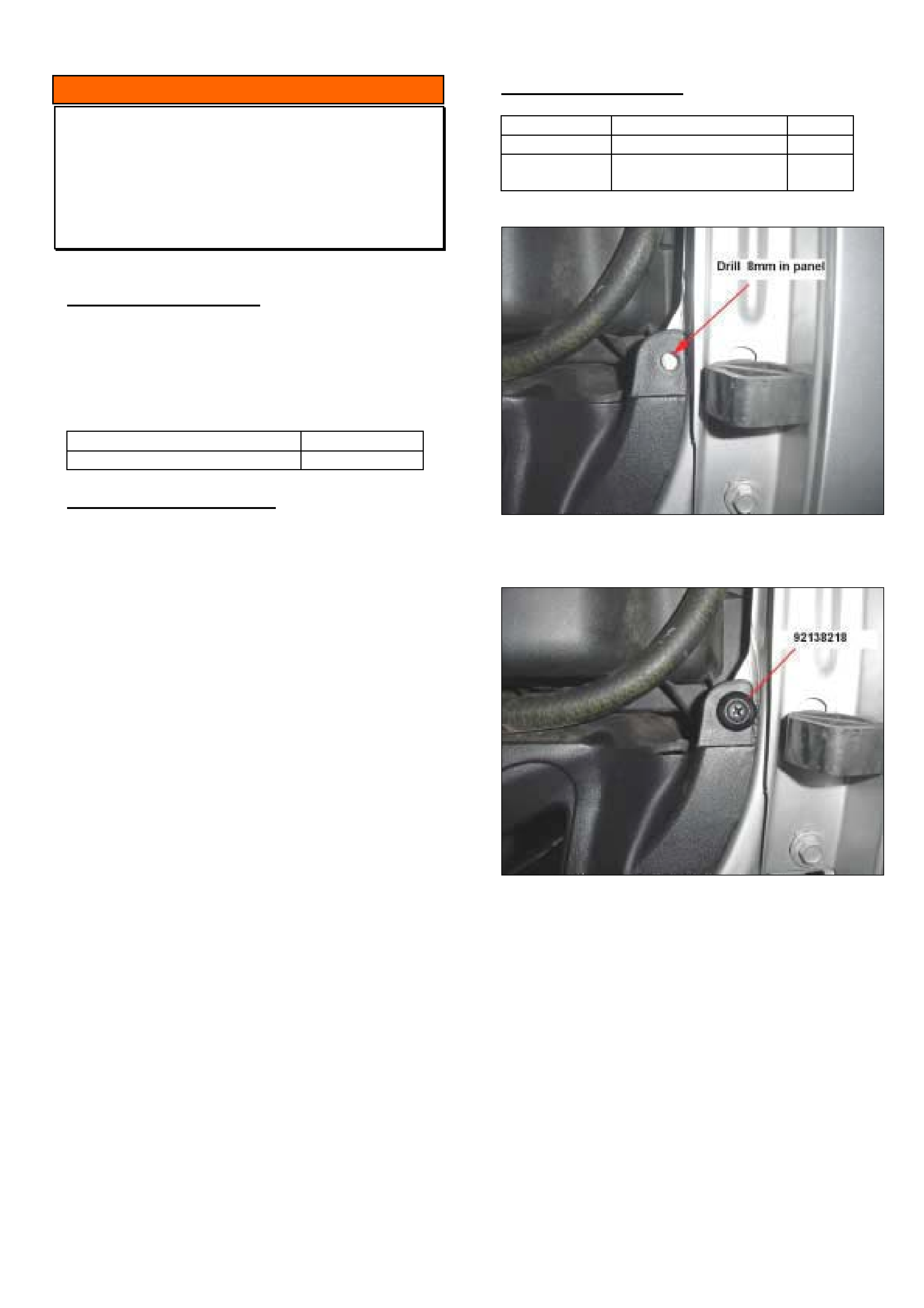
HOLDEN SERVICE TECHLINE________________________________________________________________ JUNE, 2003
10
INFORMATION
Change To Upper Radiator Shroud
Attachment on LHS
VTII, VX, VY, VU, V2, All with Gen III
(GROUP 6K) TL470-0306
PRODUCTION CHANGE
An additional fastener has been added to the left
hand side of the upper radiator shroud.
Revised shrouds with additional fastener on LHS
have been fitted to vehicles from:
ISOVIN: Build Date:
6G12X14F33L978113 19/02/2003
SERVICE REPLACEMENT
Whenever fitting a new shroud p/n 92160585 to a
vehicle built prior to the above breakpoint a hole will
need to be drilled in the body panel to take an extra
fastener.
Procedure.
1. Install the new shroud in position with 4 existing
fasteners.
2. Drill 8mm hole in panel at outer position as
shown in Figure 1. Ensure when drill breaks
through that it does not touch other components
underneath.
3. Apply rust inhibitng paint to exposed metal
surfaces.
4. Install new fastener as shown in Figure 2.
5. All labels from the old shroud should be
transferred to the new shroud. Fit new labels if
required. Refer Partfinder for correct label part
numbers.
PARTS INFORMATION
Part No.: Description: Qty:
92138218 Fastener 1
92160585 Radiator shroud
upper
1
Figure 1.
Figure 2.

HOLDEN SERVICE TECHLINE___________________________________________________________JULY, 2003
2
INFORMATION
DTC P0601 Sets After SPS Programming
Using TIS 2000 CD Version 42 & 43
VY V6 Cab Chassis
(GROUP 6C) TL535-0307
PROBLEM DESCRIPTION
It has been discovered that DTC P0601 (V6 PCM –
Powertrain Control Module Memory) sets after
performing SPS reprogramming of the Powertrain
Control Module (PCM) using TIS 2000 version 42 &
43.
The check powertrain lamp will illuminate
continuously and the DTC will not clear.
The cause of this DTC is a faulty calibration file,
which was released on TIS 2000 CD 42 & 43.
SERVICE RECOMMENDATION
It should not be necessary to reprogram the PCM in
any Cab Chassis, as there is no later calibration than
the one programmed in production.
The present calibration part numbers displayed on
TIS 2000 will be different between the Service and
Production calibration although the calibration is
identical.
SERVICE RECTIFICATION
If you believe that you need to replace or reprogram
the PCM in any V6 Cab Chassis a TAS nominated
contact should contact Holden Technical Assistance.
TIS 2000 version 44 will have revised software, which
will enable programming where required.
SERVICE FIX
Radio Popping Noise
ZC
(GROUP 12) TL520-0307
PROBLEM DESCRIPTION
Investigations show that the radio can experience a
“popping” noise heard through the speakers.
Investigations have found that the above condition;
• will only occur if the battery open circuit voltage
is low and,
• is initiated by pressing most buttons on the radio
after engine start up. Eg Station preset buttons.
Investigations have also shown that on vehicles with
the complaint condition, charging the battery to
maximum charge solves the problem.
SERVICE RECTIFICATION
Retailers are advised to check all new vehicles for
the problem during pre delivery.
If detected, charge the battery to maximum capacity
as per Retailer letter 82/00.
SERVICE PROCEDURE
Clutch Bleed Screw Correct Torque
All with Gen III V8 & MM6 M/T
(GROUP 7A) TL536-0307
PROBLEM DESCRIPTION
Excessive wear has been noticed on clutch slave
cylinder bleed screw seats, on warranty replaced
slave cylinders returned via REPAC. This is most
likely caused by over torqueing of the bleed screw.
SERVICE RECTIFICATION
Clutch slave cylinder bleed screws must be torqued
to the correct nominal torque of 18 Nm (tolerance:
15-20 Nm).
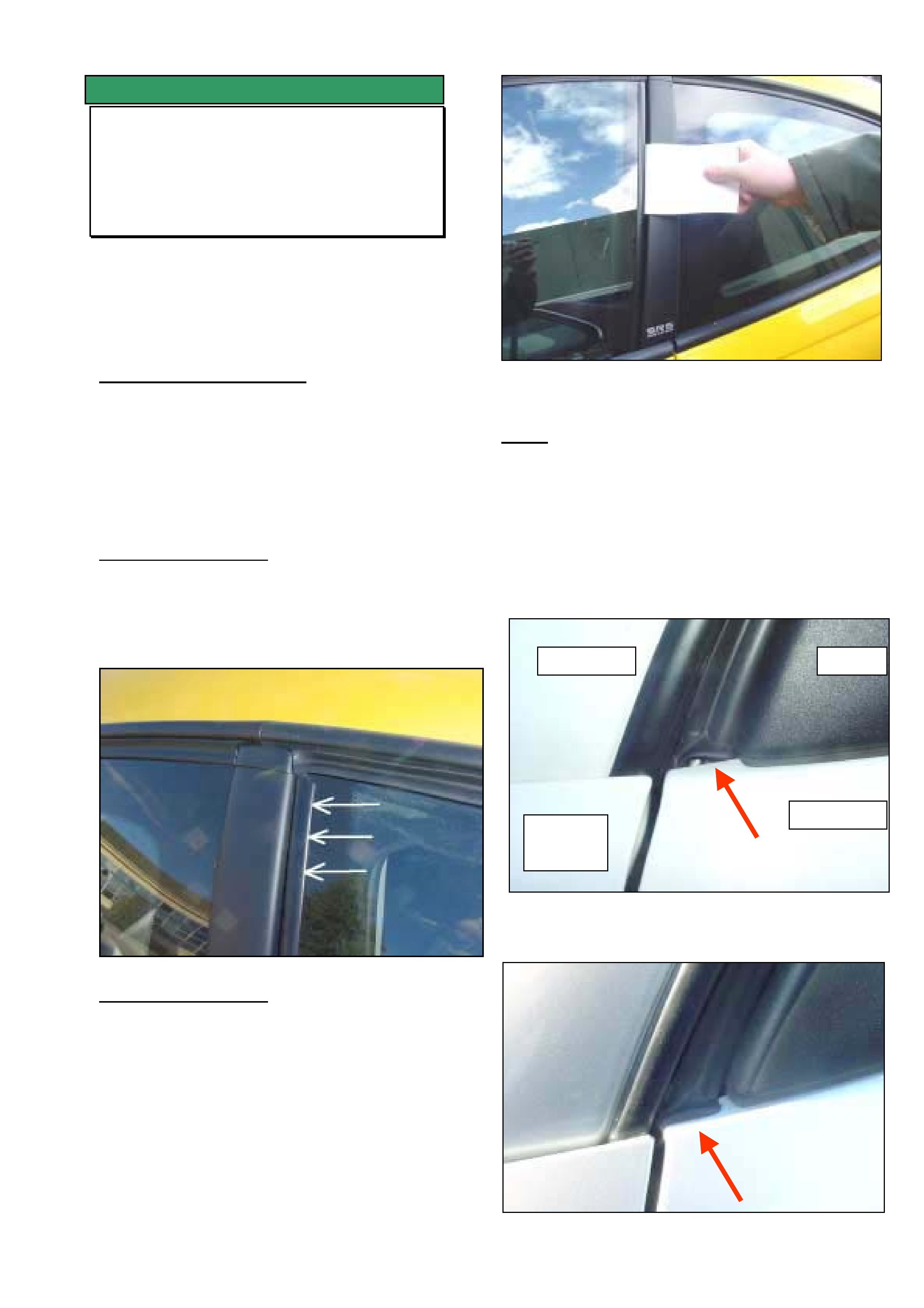
HOLDEN SERVICE TECHLINE___________________________________________________________JULY, 2003
3
SERVICE FIX
Front Door Wind Noise
V2, VY, WK
(GROUP 1) UPDATE TL350A-0307
This Techline supercedes the previous one in
Issue 9, Oct, 2002. It is updated by adding VY &
WK models and two additional causes of wind
noise.
PROBLEM DESCRIPTION
Customer complains of excessive windnoise (air
rush / turbulence) coming from the driver or
passenger doors.
Investigations show three major sources of wind
noise can be as follows:
Area 1. (Refer Figure 1)
A gap between the guide rail (forward edge) and
the glass can cause wind rush noise. Check for
gap over full length of window using a .05mm
feeler gauge.
Figure 1.
Area 2. (Refer Figure 2).
A gap between the B pillar weatherstrip and the
drop window guide rail can cause wind rush
noise.
The best method for checking this gap is to slide
a piece of paper (or business card) between the
window rail and B pillar weatherstrip as shown.
If the paper slides easily with no resistance then
a gap exists and must be rectified. If a slight
resistance can be felt for the full length of the
seal then no work is required in this area.
Figure 2. Check gap over full length of window
Area 3. (Refer Figure 3A and 3B).
A gap between the door frame weatherstrip and
the door panel at the bottom of the A pillar as
shown in Figure 3A can cause a wind rush
noise.
Figure 3B shows how the weatherstrip should
look when installed correctly.
Figure 3A. Incorrect installation (Gap showing)
Figure 3B Correct installation (No gap)
LH A Pilla
r
LH Front
Guard
Mirro
r
LHF Doo
r
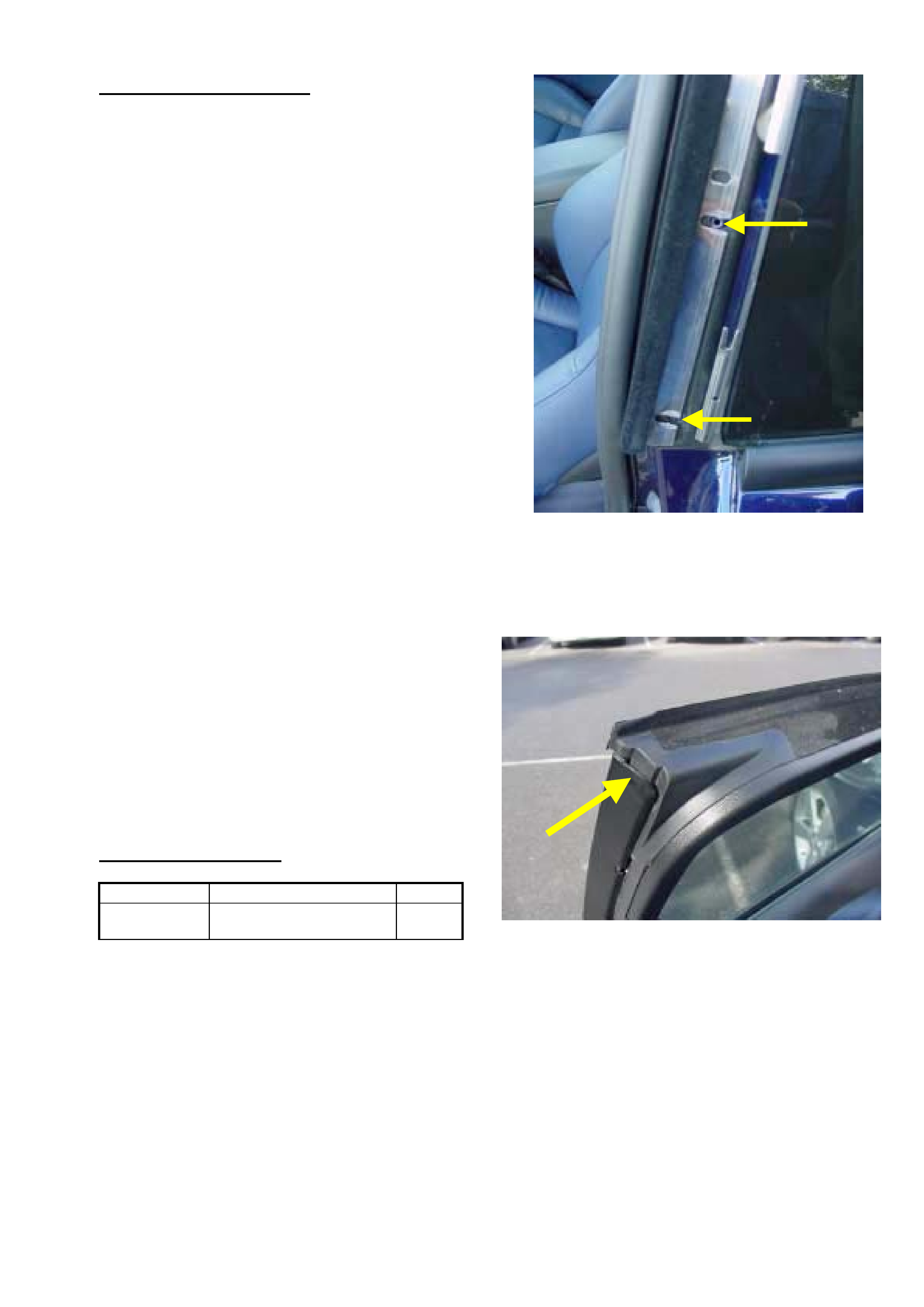
HOLDEN SERVICE TECHLINE___________________________________________________________JULY, 2003
4
SERVICE RECTIFICATION
Summary: On any vehicle with front door wind
noise check the 3 areas described and rectify as
required.
Area 1.
If there is a gap as described above, carefully
apply a smear of urethane as required to
eliminate the gap.
Ensure all excess is wiped away.
Area 2.
If there is a gap as described above, remove the
B pillar moulding (refer procedure in PV SIP) and
proceed to adjust the B pillar weatherstrip until
the gap is eliminated. Use
If the weatherstrip does not have enough
adjustment, modify the slots as shown in Figure
5 to achieve the desired condition.
NOTE. The desired condition is achieved when
a slight resistance is felt whilst withdrawing the
paper.
Tighten screws and refit the B pillar moulding.
Operate the window and check that in the
upwards direction, the top edge of the guide rail
does not tend to “dig” into the B pillar
weatherstrip. If this occurs, use a nylon
hammer and carefully tap the very top edge of
the guide rail towards the window (away from the
weatherstrip). Refer Figure 6.
Area 3.
If there is a gap as described above, remove the
weatherstrip from the door frame and begin to
refit from the bottom edge of the door at the
lower A pillar. Figure 4 shows how the
weatherstrip should look when installed correctly.
PARTS INFORMATION
Part No.: Description: Qty:
92146444 Sealer urethane 300ml
tube
1
Figure 5. Modify 2 lower slots as shown only if
required to achieve correct adjustment.
Figure 6.

HOLDEN SERVICE TECHLINE___________________________________________________________JULY, 2003
5
INFORMATION
Adhesive Residue On New Vehicles
As Delivered From Port Of Entry
TS, XC, ZC
(GROUP 1) TL528-0307
PROBLEM DESCRIPTION
The above vehicles usually have a protective
plastic film on the horizontal panels to protect
them during shipping.
This plastic film is removed at Port Of Entry
(POE). Any traces of the adhesive used to apply
the film to the panel are also removed at POE .
However, there have been a few reports from
Retailers of new vehicles, during pre delivery
detailing, having traces of this adhesive on
panels. It is also reported that this material is
extremely hard to remove.
SERVICE RECOMMENDATION
Should vehicles be received “off the truck” with
adhesive residue marks on panels, immediately
remove with product such as Prepsol.
Failure to remove as soon as possible may
result in this residue “curing” onto panels thus
making future removal very difficult.
SERVICE FIX
Glovebox Lid Distorted
VY
(GROUP 1) TL536-0307
PROBLEM DESCRIPTION
Some customers may report that the glove box
lid looks distorted particularly on the left hand
side.
PRODUCTION RECTIFICATION
The glovebox lid has been revised by adding
extra strengthening ribs and changing to a more
heat stable material.
Vehicles were fitted with revised glovebox
assemblies from:
ISOVIN: Build Date:
6G1YK52A73L982236 10 Mar 2003
SERVICE RECTIFICATION
On any vehicle with the above condition, install a
revised glovebox assembly which includes the
inner and outer panels. In Partfinder this
assembly is known as a “Compartment asm.
instrument panel”.
The lock assembly will need to be transferred
across from the old glovebox.
Refer to Partfinder for the latest part number
applicable to the trim colour in the customers
vehicle.
PARTS INFORMATION
Part No.: Description: Qty:
refer
Partfinder
Compartment assembly
instrument panel
1
WARRANTY CLAIM INFORMATION
Use Labour Times information in Warranty
Information section of current PV SIP CD
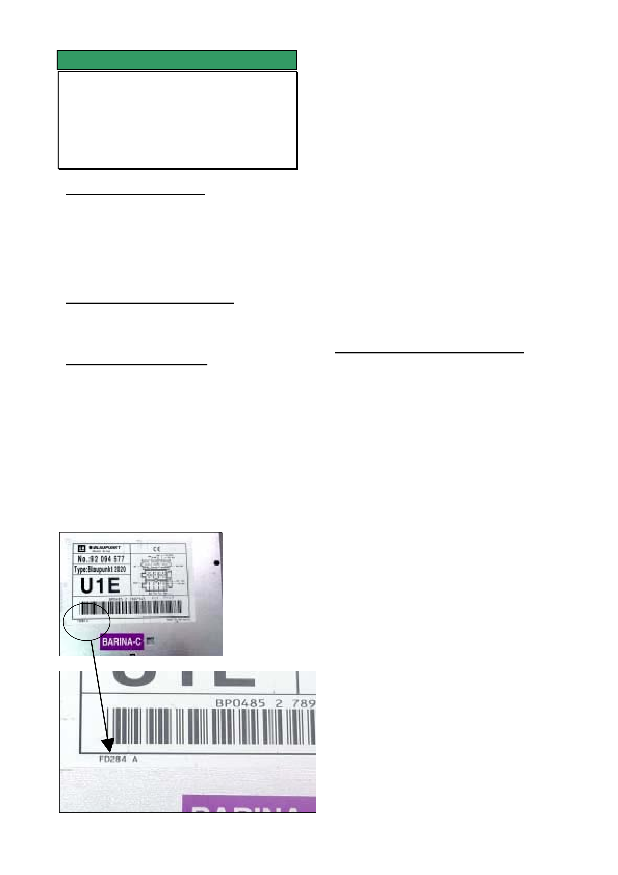
HOLDEN SERVICE TECHLINE___________________________________________________________JULY, 2003
6
SERVICE FIX
Blaupunkt 520 / 2020 CD Player
Inoperative Due To CD Not Ejecting
SB / JR / JS / TS / TT / XC
(GROUP 12) TL479-0307
PROBLEM DESCRIPTION
Customers may complain of Blaupunkt 520 &
2020 CD players becoming inoperative due to
CD’s not ejecting.
After investigation into the root cause Blaupunkt
have made a software revision to rectify this
condition.
PRODUCTION RECTIFICATION
Blaupunkt implemented the software revision in
all CD player fitted to vehicles at the Port Of
Entry on the 1st of November 2001.
SERVICE RECTIFICATION
If you have a customer who presents a vehicle
with the above condition the following steps
should be performed.
Step 1. Determine if the CD player is pre
or post break point by removing it and inspecting
the bottom left corner of the label attached to the
top cover for the FD number. Refer photographs
below.
Pre breakpoint units have an FD number below
FD187. Post break point units have an FD
number FD187 or higher.
If unit is Pre breakpoint go to Step 2.
If unit is Post breakpoint go to Step 3.
Step 2. If the CD player is pre break point,
contact Blaupunkt as per the Special Warranty
Component Replacement Requirement
section in SIP and request approval to replace.
If your Retailship Outlet does not stock a
replacement CD player refit the original unit and
rebook the customer to enable fitment of the
new unit when it arrives.
Step 3. If the CD player is post break
point, removing it from the vehicle to inspect the
label will have rectified the condition
(disconnecting the power supply).
Refit the CD player, check the operation and
submit a PIR indicating the FD number on the
label and the serial number stamped into the
side of the CD player case.
WARRANTY CLAIM INFORMATION
Use Labour Times information in Warranty
Information section of current PV SIP CD
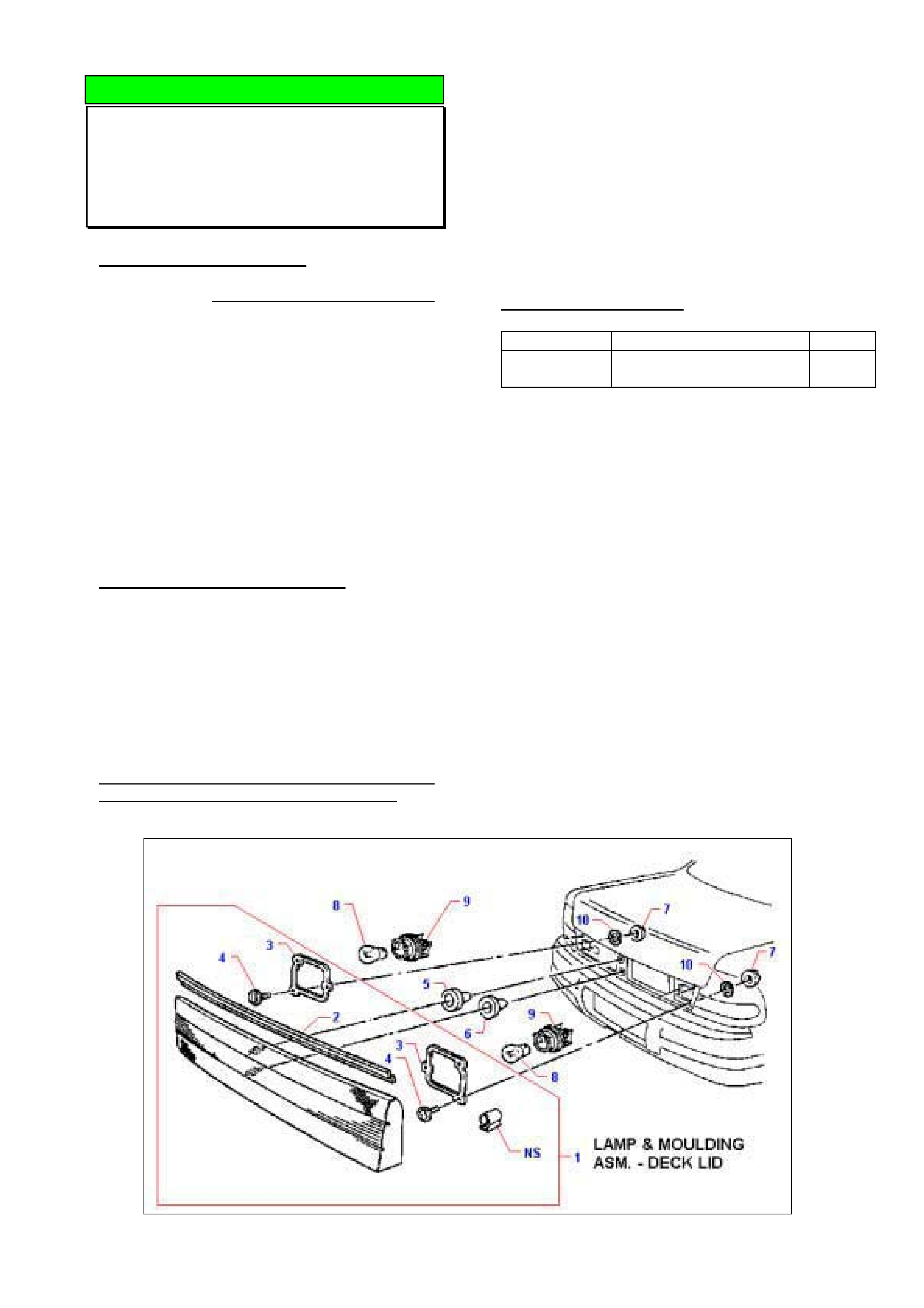
HOLDEN SERVICE TECHLINE___________________________________________________________JULY, 2003
7
DIAGNOSIS HINT
Rear Décor Panel Condensation
WH
(GROUP 1) TL398-0307
PROBLEM DESCRIPTION
Some deck lid lamp and moulding assemblies
are being replaced unnecessarily when
condensation is apparent on the lens.
Because this moulding is vented to atmosphere,
small amounts of condensation may appear
depending on the relative humidity and
temperature conditions. This is a temporary
condition which will eventually disappear and
does not cause any adverse reaction.
NOTE: Normal condensation should not be
confused with the accumulation of water in the
bottom of the moulding. In these cases, damage
or poor sealing should be investigated.
SERVICE RECOMMENDATION
Diagnosis of Condensation.
Condensation can be defined as a visible
concentration of small droplets of water formed
in localised areas on the inside surface of the
lens, surrounded with fogging(misting).
Condensation is usually found in the corners with
little or no internal air flow, and towards the top
where the air is warmest.
Do not replace lamp and moulding assemblies
when condensation is apparent on the lens.
Diagnosis of Water Ingress
Where there is a collection of water on the
bottom surface of the moulding:
• check for poor sealing (incorrectly located,
damaged, perished or missing seals).
• check for damage to external surfaces
(cracks , chips, dents or gouges.
Repair or replace moulding / seals as necessary
to address water ingress.
PARTS INFORMATION
Part No.: Description: Qty:
92142116 Lamp & Moulding Asm –
deck lid
1
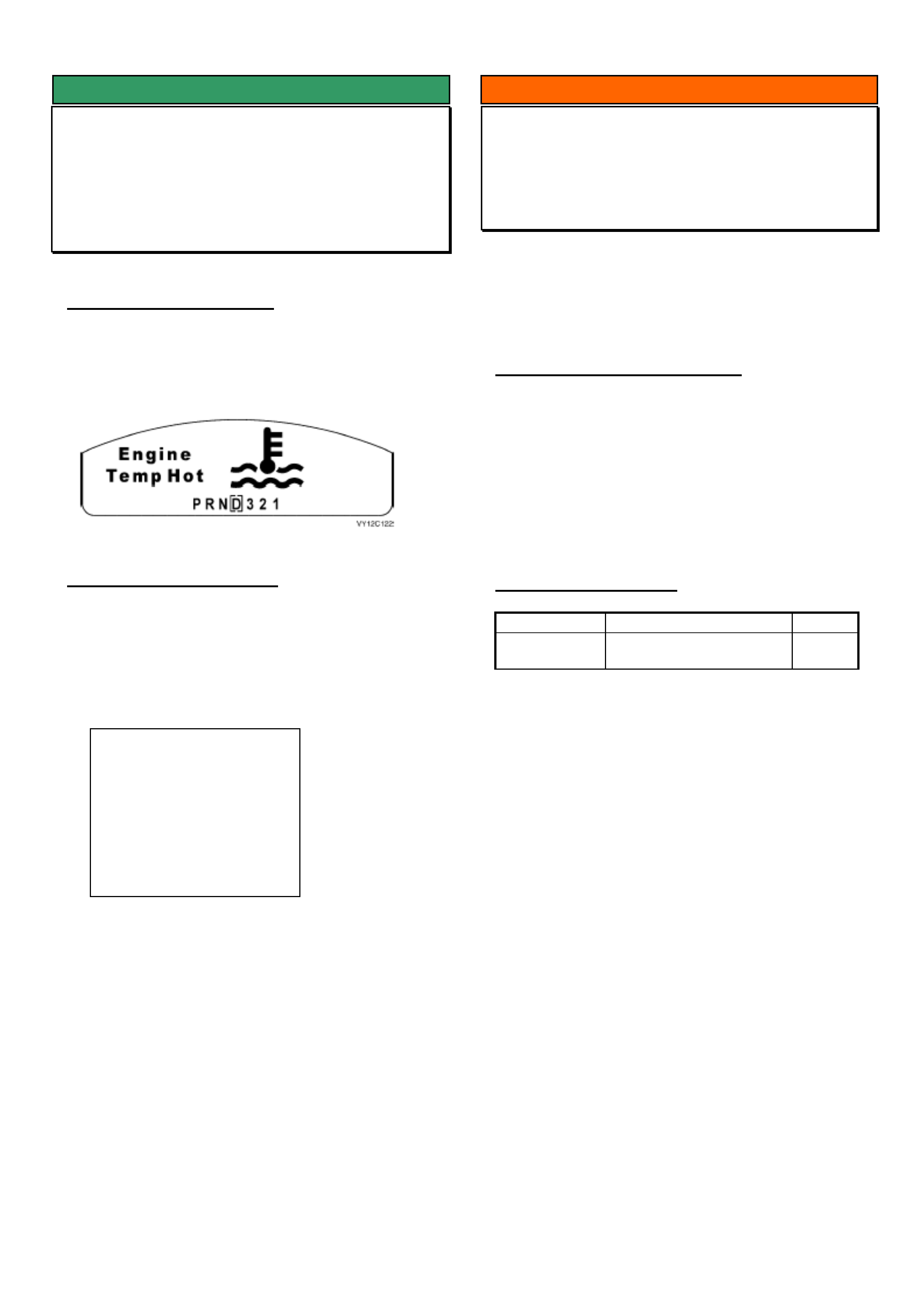
HOLDEN SERVICE TECHLINE_________________________________________________________________AUGUST, 2003
5
SERVICE FIX
Instrument Cluster Programming Error
Using Tech 2 Software Version 12.305
VY / V2II / WK
(GROUP 12) TL543-0308
PROBLEM DESCRIPTION
After programming the instrument configuration using
Tech 2 software version 12.305 from TIS CD 43.1 the
following icon is displayed on the Multi Function
Display and will not clear.
SERVICE RECTIFICATION
To rectify this condition perform the following steps;
Step 1.
Re-enter the configuration sub menu (an example
displayed below) within the instrument cluster
programming menu.
Step 2.
Scroll down to the Engine Type.
Step 3.
Select Modify, (there is no need to change anything).
Step 4.
Select Program.
This will rectify the condition. If any problems are
encountered using this method an alternate method is
to change the Tech 2 software back to 12.2 and
perform the standard configuration.
INFORMATION
Propshaft Front Coupling Improvements
VTII GenIII & M/T, Sedan & Wagon
(GROUP 4) TL346-0308
There has been an improvement to the rubber
material used on the propshaft front coupling on the
above models.
SERVICE RECOMMENDATION
Whenever a propshaft front rubber coupling
replacement is required use latest repair kit as shown
in Parts Information below.
The procedure for coupling replacement is found in
SIP as follows:
VT Series I/Section 4C – Propellor Shaft & Uni joints
/2 Service Operations/2.3 – Front Flexible Joint
PARTS INFORMATION
Part No.: Description: Qty:
92146806 Repair Kit Rubber
Coupling-
1
Parts Managers Note:
Any of the previous kits part number 92142811 should
be returned to HSPO for credit via the CRRM system.
Configuration
(4) 2004 WK Series
Instrument
Country
Australia/NZ
Engine Type V8
Speedometer
6301
SRS Configuration 6
Loop SRS
Transmission Type
Automatic
Occupant Climate Control Present
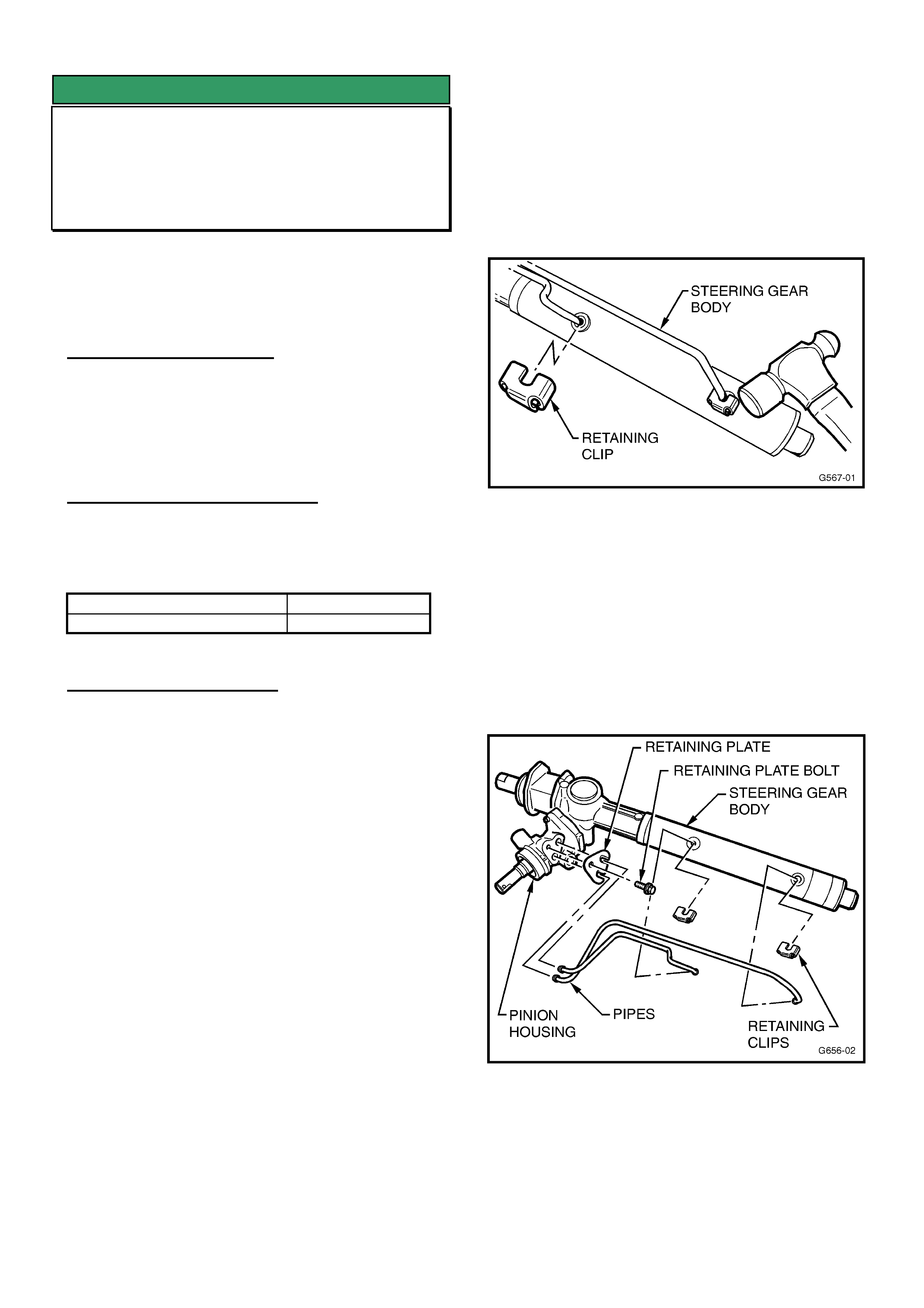
HOLDEN SERVICE TECHLINE_________________________________________________________________AUGUST, 2003
6
SERVICE FIX
Steering Gear Squeak
JR, JS, JS II
(GROUP 9) UPDATE TL504-0308
This Techline supercedes the previous one in Issue
11, Nov, 2001. It includes details of an oil additive
which provides additional resistance to squeaks.
PROBLEM DESCRIPTION
Customers may complain of a squeak noise from the
steering column/rack area when turning the steering
wheel from side to side. Dealer investigation narrows
the source of the squeak to the steering gear.
PRODUCTION RECTIFICATION
Revised pinion housing seals made of a different
material have been fitted to steering gears in
production from:
ISOVIN: Build Date:
W0L0JBF6817005134 06/09/00
SERVICE RECTIFICATION
For complaint vehicles built after the above
breakpoint or which have already had the rebuild kit
92144993 fitted, add 50 ml of oil additive p/n
90004033 to the power steering fluid.
___________________________________________
For complaint vehicles built prior to the above
breakpoint install a rebuild kit that contains the revised
seals as per following procedure.
1. Obtain a repair kit as detailed in the “Parts
Information” section and ensure the contents of the
kit are as follows:
a. 1 x Valve Housing
b. 1 x Lower Housing Pinion Seal
c. 1 x Needle Bearing Sleeve
d. 1 x Upper Housing Pinion Seal
e. 1 x Retaining Washer
f. 1 x Large O-ring
g. 2 x Retaining Clips
h. 4 x Small O-rings
NOTE. Parts (a) to (e) should already be assembled.
2. Remove the steering gear from the vehicle as per
the procedures detailed in the latest TIS2000 CD.
This repair should be conducted in a clean
environment to minimise the chance of
contamination.
3. Mark the steering gear pipes with a permanent
marker or paint pen to clearly identify where to
reinstall them.
4. Using a small hammer (16 oz or 450gm ball pein is
ideal), carefully tap the pipe retaining clips to
remove them from the steering gear body. Discard
these clips. Refer to Figure 1.
Figure 1
5. Remove the pipe retaining plate bolt from the pinion
housing using a Torx T30 bit. Remove the pipe
retaining plate from the steering gear.
6. Carefully pull the pipes from the steering gear body
and pinion housing. THESE PARTS ARE NOT
SERVICED SEPARATELY AND CANNOT BE
PURCHASED IF DAMAGED! Remove the sealing
O-rings from the pipes and discard them. Refer
Figure 2.
Figure 2
7. Remove the two bolts securing the pinion housing
to the steering gear body using 5mm internal hex
bit.
8. Twist the housing to break the seal and remove it
from over the pinion shaft. Refer to Figure 3.
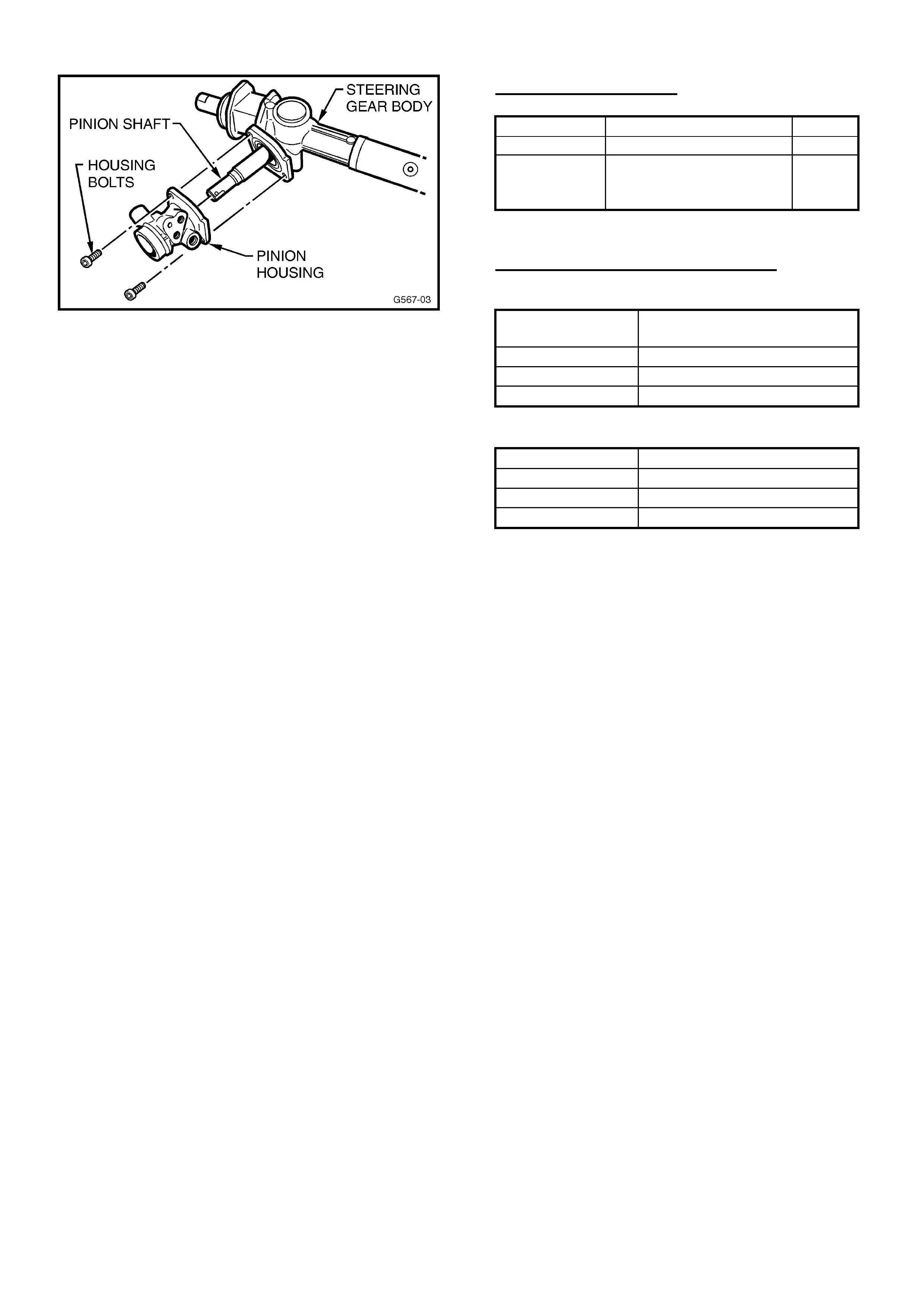
HOLDEN SERVICE TECHLINE_________________________________________________________________AUGUST, 2003
7
Figure 3
9. Remove the large O-ring installed in the steering
gear body that seals the pinion housing and discard
it.
10. Locate the replacement large O-ring in the rebuild
kit and lubricate it with power steering fluid.
11. Carefully install the large O-ring over the spigot in
the steering gear body.
12. Inspect the seals fitted to the valve housing for
grease between the sealing lips. If none is present,
fill the space between the sealing lips with an
Extreme Pressure Grease to NLGI # 00
specification, such as Castrol EPL00.
13. Carefully fit the new pinion housing over the pinion
shaft.
14. Install the two bolts through the pinion housing and
into the steering gear body. Torque these bolts to
17 Nm.
15. Locate the replacement small O-rings in the rebuild
kit and lubricate them with power steering fluid.
16. Carefully install the small O-rings onto the steering
gear pipes.
17. Install the long pipe back into the correct ports in
the steering gear body and pinion housing.
18. Install the short pipe back into the correct ports in
the steering gear body and pinion housing.
19. Install the pipe retaining plate and bolt back onto
the pinion housing. Torque the retaining bolt to 12
Nm.
20. Locate the new pipe retaining clips in position on
the pipe to gear interface. Using the small hammer,
lightly tap these clips onto the rack until they are
home against the pipes.
21. Reinstall the steering gear into the vehicle as per
the procedures detailed in the latest TIS2000 CD.
22. Add rear axle oil additive part number 90004033 (50
ml) into power steering fluid.
PARTS INFORMATION
Part No.: Description: Qty:
92144993 Repair Kit – P/S 1
90004033 Oil additive-50ml
bottle. (Labelled as
Rear Axle Oil Additive)
1
WARRANTY CLAIM INFORMATION
For vehicles repaired under warranty.
Description Install Pinion Housing
Repair Kit & oil additive
Labour Op. No. M000184
Time 3.7 hr
Failure Code 40
Description Install oil additive only
Labour Op. No. M000196
Time 0.2 hr
Failure Code 40
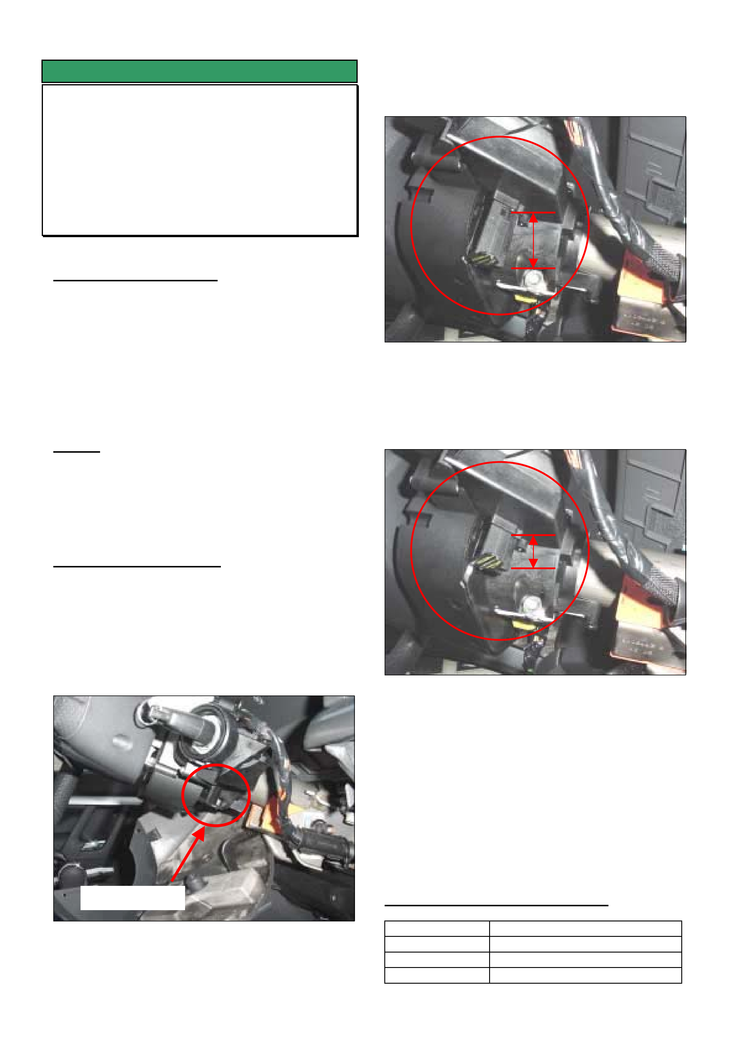
HOLDEN SERVICE TECHLINE_________________________________________________________________AUGUST, 2003
8
SERVICE FIX
Ignition Key Can Be Removed In Any
Gear
DTC B3601 (Key Capture Relay Circuit
Malfunction) Present in CIM
ZC Vectra AF32 / AF22
(GROUP 12) TL550-0308
PROBLEM DESCRIPTION
Customers may report that they are able to remove
the ignition key with the gear selector in any gear. (ZC
Vectra is designed to stop the ignition key being
removed unless the gear selector is in park.)
When performing a DTC check Technicians may find
DTC B3601 Key Capture Relay Circuit Malfunction
present in the Column Integration Module (CIM).
CAUSE
If the ignition key is forced to the off position when the
automatic transmission selector is still in gear the key
capture relay will dislodge from the CIM and allow the
ignition key to be removed.
SERVICE RECTIFICATION
Summary. Relocate Key Capture Relay into the
Column Integration Module as follows.
1. Remove the upper and lower steering column
covers as per TIS 2000 and inspect the lower right
hand side of the CIM below the ignition barrel as per
Figure 1. below.
Figure 1.
Figure 2 below is a picture of the Key Capture Relay
when it is dislodged.
Figure 2.
2. Pushing up on the Key Capture Relay until a
click is heard will relocate it into the CIM as shown in
the picture below.
Figure 3.
3. When the Key Capture Relay is correctly
relocated reassemble the steering column covers as
per TIS 2000 and use Tech 2 to clear DTC B3601.
IMPORTANT NOTE FOR SERVICE ADVISORS:
Discuss with your customer the correct operation of the
ignition switch to avoid this problem reoccurring in the
future.
WARRANTY CLAIM INFORMATION
Description Refitting Key Capture Relay
Labour Op. No N000444
Time 0.5 hr
Failure Code 28 rattle
Key Capture Relay
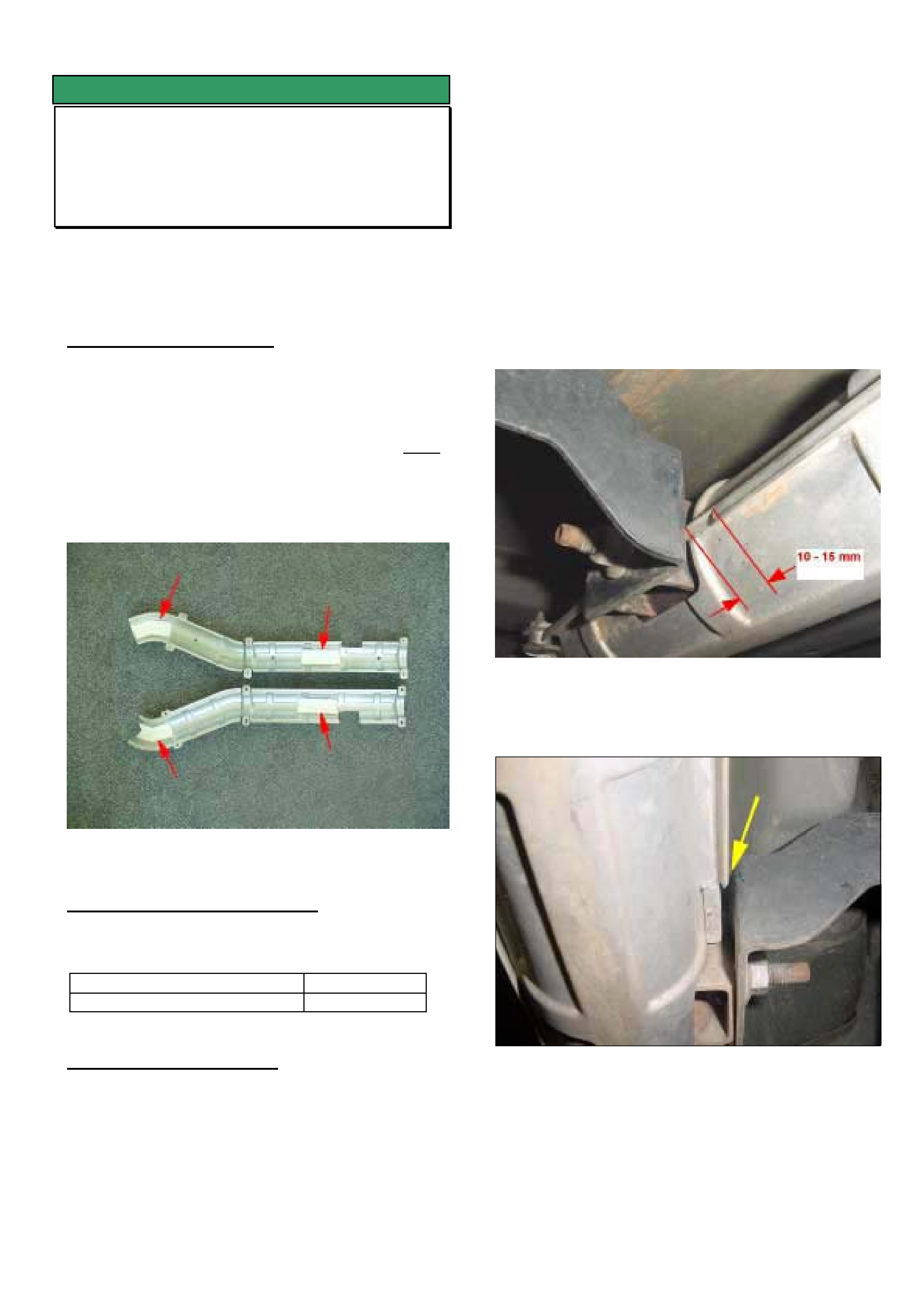
HOLDEN SERVICE TECHLINE_________________________________________________________________AUGUST, 2003
9
SERVICE FIX
Front Exhaust Pipe Heat Shield Vibrates
WK with Gen III
(GROUP 8) REVISED TL514A-0308
This Techline supercedes the previous one in Issue 6,
2003. It includes additional service fix and parts
information.
PROBLEM DESCRIPTION
A buzz/vibration from front exhaust pipe heat shields
which occurs on takeoff under light loads such as
driving uphill. Refer to Figure 4 for location of shields
in question.
The cause of the buzz is a combination of loose
insulation pads and insufficient clearance between the
shields and exhaust support bracket. The insulation
pads are adhered to the shields as shown in Figure 1.
They may become detached and move around.
Figure 1. Location of insulation pads
PRODUCTION RECTIFICATION
Exhaust heat shields with revised adhesive for
attaching insulators have been fitted to vehicles from:
ISOVIN: Build Date:
6G1KY54R74L119610 12/5/03
SERVICE RECTIFICATION
To rectify a complaint vehicle proceed as follows.
A. For vehicles built prior to above breakpoint:
1. Fit a set of new heat shields obtained from HSPO.
2. Crimp shields together as described in Crimping
Procedure below.
B. For vehicles built after the above breakpoint:
1. Inspect heat shield insulation pads. If loose, brittle
or missing, fit new heat shields from HSPO.
2. Crimp shields together as described in the
following procedure.
Shield Crimping Procedure. (refer Figure 2 & 3)
At a distance of 10 to 15mm forward from the exhaust
support bracket, cut the flange of the upper shield
(use tin snips) then use multigrips to crimp the shields
together as shown.
NOTE: This crimping process only needs to be done
on the “inboard” side of the heat shields as shown.
Figure 2. Shows LHS heat shield assembly after
crimping flanges together.
Figure 3. Shows crimping of RHS heat shield
assembly. (Note. There must be clearance between
shield and bracket as shown).
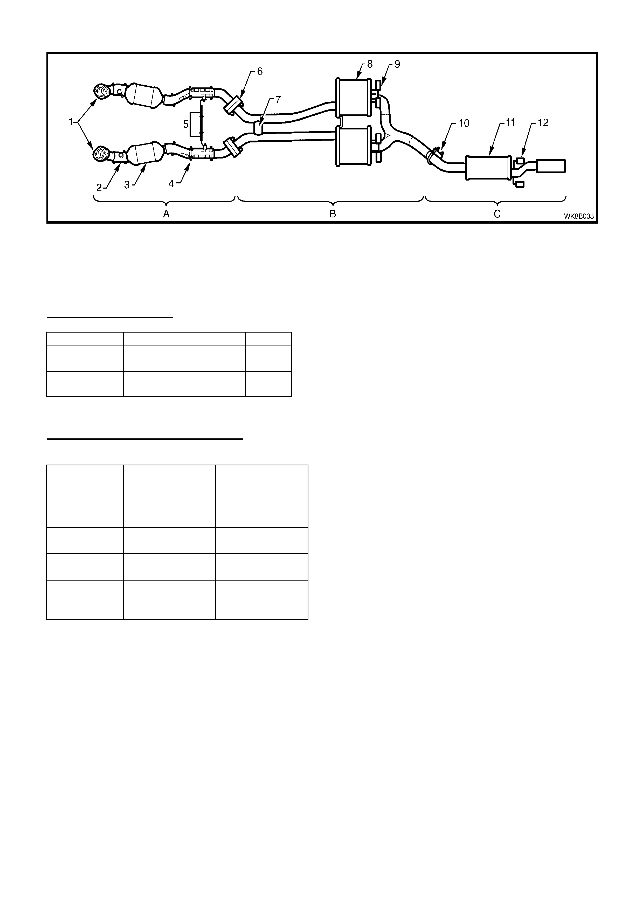
HOLDEN SERVICE TECHLINE_________________________________________________________________AUGUST, 2003
10
Figure 4. Item 4 = heat shield
Item 5 = exhaust support bracket
PARTS INFORMATION
Part No.: Description: Qty:
92147239 Exhaust heat shield –
Right side (2 halves)
1
92147240 Exhaust heat shield –
Left side (2 halves)
1
WARRANTY CLAIM INFORMATION
Description Crimp front
exhaust heat
shields only –
both sides
Replace &
crimp front
exhaust heat
shields – both
sides
Labour Op.
No.
L000220 L000217
Time
0.3 0.5 hr
Failure
Code
36 vibration 36 vibration
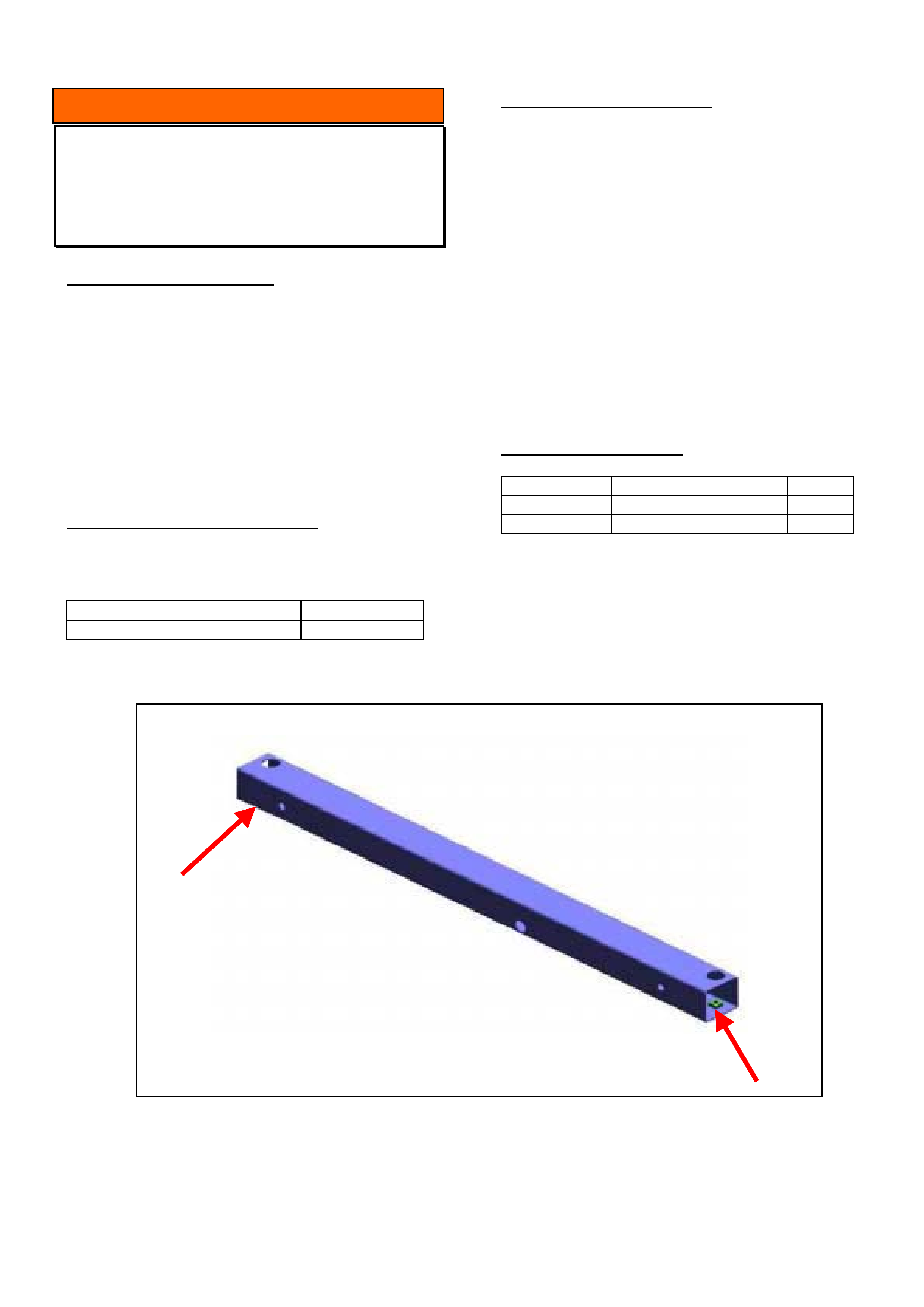
HOLDEN SERVICE TECHLINE ________________________________________________________________ AUGUST, 2003
11
INFORMATION
Tow Bar Attaching Bolts
VY Regular Cab
(GROUP 1) TL539-0308
PROBLEM DESCRIPTION
Some Regular Cab vehicles were built with two M10
weldnuts in the rear frame crossbeam instead of
M12 weldnuts. These weldnuts are used for
installation of the towbar assembly 92160067.
NOTE: The towbar kit is only supplied with M12 bolts
Refer Figure below for location of the weldnuts
concerned.
PRODUCTION RECTIFICATION
M12 weldnuts have been fitted to the rear cross
beam on vehicles from:
ISOVIN: Build Date:
6G1YK03A73L141969 14/07/03
SERVICE RECTIFICATION
If, during installation of the towbar, it is observed that
the vehicle has M10 weldnuts the following action
should be taken.
Order two of part number 11091693 (M10 bolt) and
two of part number 11010024 (washer) from HSPO.
Install M10 bolts and washers in the location shown
below and torque to 60 Nm.
TORQUE M10 BOLT to 60 Nm
NOTE: Testing has shown it is acceptable to use
M10 bolts in the 2 locations in question provided the
specified bolts and torque are used.
PARTS INFORMATION
Part No.: Description: Qty:
11091693 M10 Bolt 2
11010024 Washer 2
Chassis Rear Cross Beam - Location Of Weldnuts Concerned.
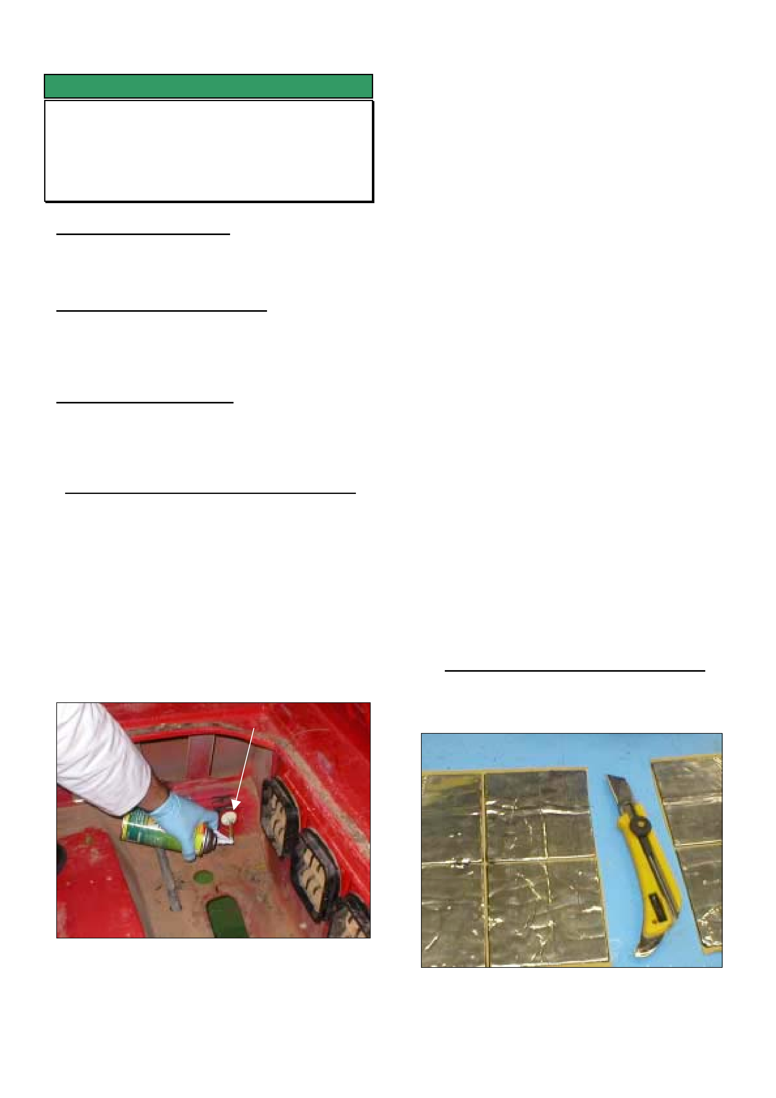
HOLDEN SERVICE TECHLINE_________________________________________________________________AUGUST, 2003
12
SERVICE FIX
Cabin – Dust Entry
VU, VY Utility
(GROUP 1) TL509-0308
PROBLEM DESCRIPTION
Dust enters the cabin through gaps at the panel joins
in the B Pillar area.
PRODUCTION RECTIFICATION
Expanding sealer will be added to the panels in
production. Break Point summary will be updated
when information is available.
SERVICE RECTIFICATION
Summary: Seal pathways in the rocker panel and B-
pillar through which dust can enter the cabin. This
procedure may also help to prevent odours entering
the cabin.
Stage 1. - Blocking Rocker Panels - RHS & LHS
1. Remove the tonneau floor front and the both side
panel covers (Side panel covers shown Fig. 4)
2. Remove the Fuel Tank Asm in order to gain
access to the RHS rocker area ( refer SIP as
required )
3. Remove the tonneau floor drain tube and clamp
from both sides.
4. Identify the 50mm hole in the rocker panel,
shown in figure 1.
Figure 1. Blocking LHS Rocker Panel
5. The rocker panel is divided into two sections.
Inspect the inner rocker panel through the 50mm
hole and identify the second hole.
Note: For the service fix to be effective both
sections of the rocker must be filled with
expanding foam.
6. Use commercially available expandable
polyurethane foam such as Parfix "Foam Fix" by
Parburys available in a 340g container (or
equivalent). Be sure to follow the manufacturers
recommended safety procedures. Two cans may
be required to fill both sections.
7. Use a suitable solvent such as acetone for
cleaning any spillages.
8. Insert the extension tube, provided with the
expandable foam, through the second hole and
into the outer (closest to outer of vehicle) section
of the rocker panel.
9. Apply expandable foam as directed on can,
ensuring to move extension tube up and down to
fill rocker cavity completely from top to bottom.
10. Withdraw extension tube and fill the inner
(closest to centre of the vehicle) side of rocker as
shown in figure 1.
11. Repeat steps 8 - 10 for the opposite side rocker
panel, again ensuring that both sections of rocker
are completely filled.
12. Leave foam to cure and do not disturb.
Instructions on can will indicate when foam is dry.
Stage 2. Blocking the upper B-pillar areas.
1. Order 2 off large Butyl Patches 500mm x 120mm
from HSPO, P/N = 92156600.
Figure 2. Aluminium backed butyl patches used to
cover gaps.
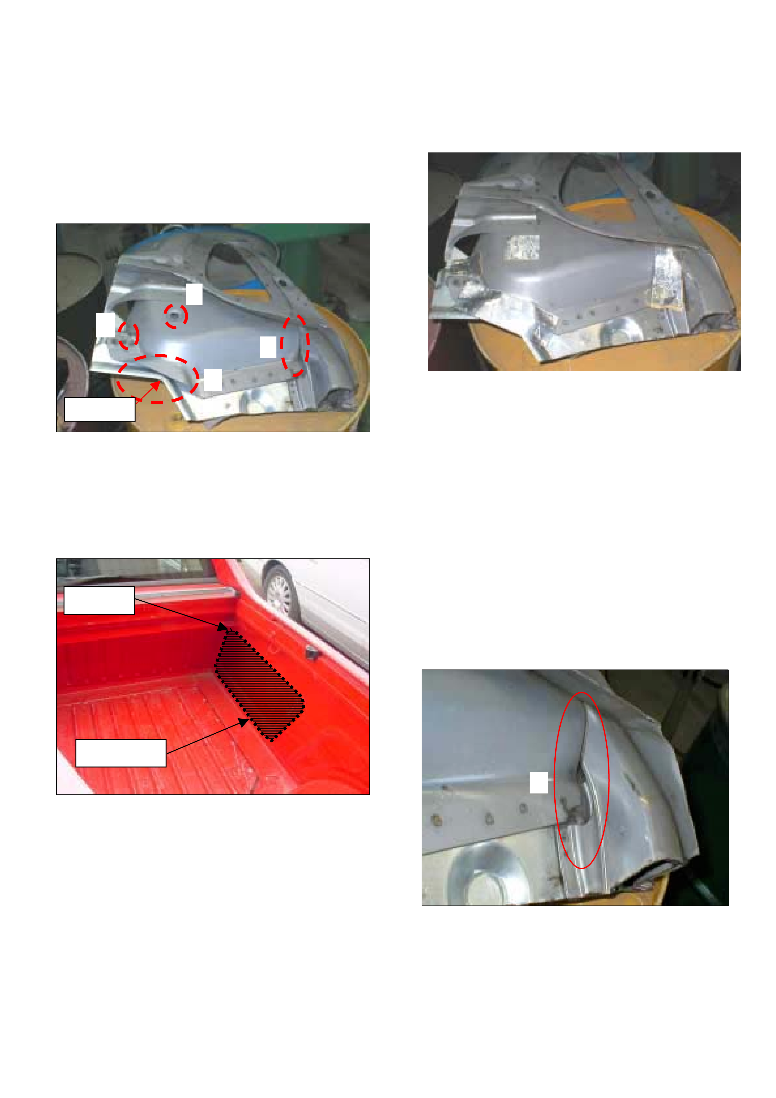
HOLDEN SERVICE TECHLINE_________________________________________________________________AUGUST, 2003
13
2. Survey between the side panel inner and outer via
the side panel opening, using your fingertips to
locate the four panel gaps as shown in figure 3.
HINT: Locate corner A as shown in figures 3 & 4.
Use corner A as your reference then navigate to the
other positions using the joins and curves shown in
the attached photos.
Figure 3. Shows cutaway section of RHS B pillar
with external panel removed. Note the four gaps in
sheetmetal that need to be covered with patches.
Figures 6 and 7 show close up views of gaps.
Figure 4 Shows location of Corner A.
3. Clean the area around gaps 1 - 4 (refer fig. 3)
with prepsol to ensure the patches adhere
correctly.
4. Cut sections of butyl patch to cover each of the
gaps. Suggested sizes are-
Gap 1 - patch size = 50mm x 120mm
Gap 2 - patch size = 60mm x 150mm
Gap 3 - patch size = 50mm x 70mm
Gap 4 - patch size = 50mm x 50mm
5. Apply patches to each of the gaps as illustrated
in figure 5 (RHS of vehicle shown). Place patches
over the difficult to apply positions first (3 & 1).
Then place patches over positions (2 & 4)
Figure 5. Shows the four gaps covered with patches
6. As application of the butyl patches is a blind
operation, exact placement of patches will be
difficult. Apply additional patches as required.
7. With your index finger feel around gaps to ensure
that they are effectively covered and then push
on the patches to make them conform and
adhere to the sheetmetal.
8. Complete the sealing operation for both sides of
the vehicle.
9. Once sealing is completed, reassemble all
components removed.
Figure 6. Close up of gap 1 which is up against the B
-pillar. All of the area enclosed by the red line should
be sealed
Side Panel
Corner A
1
3
2
4
Corner
A
1
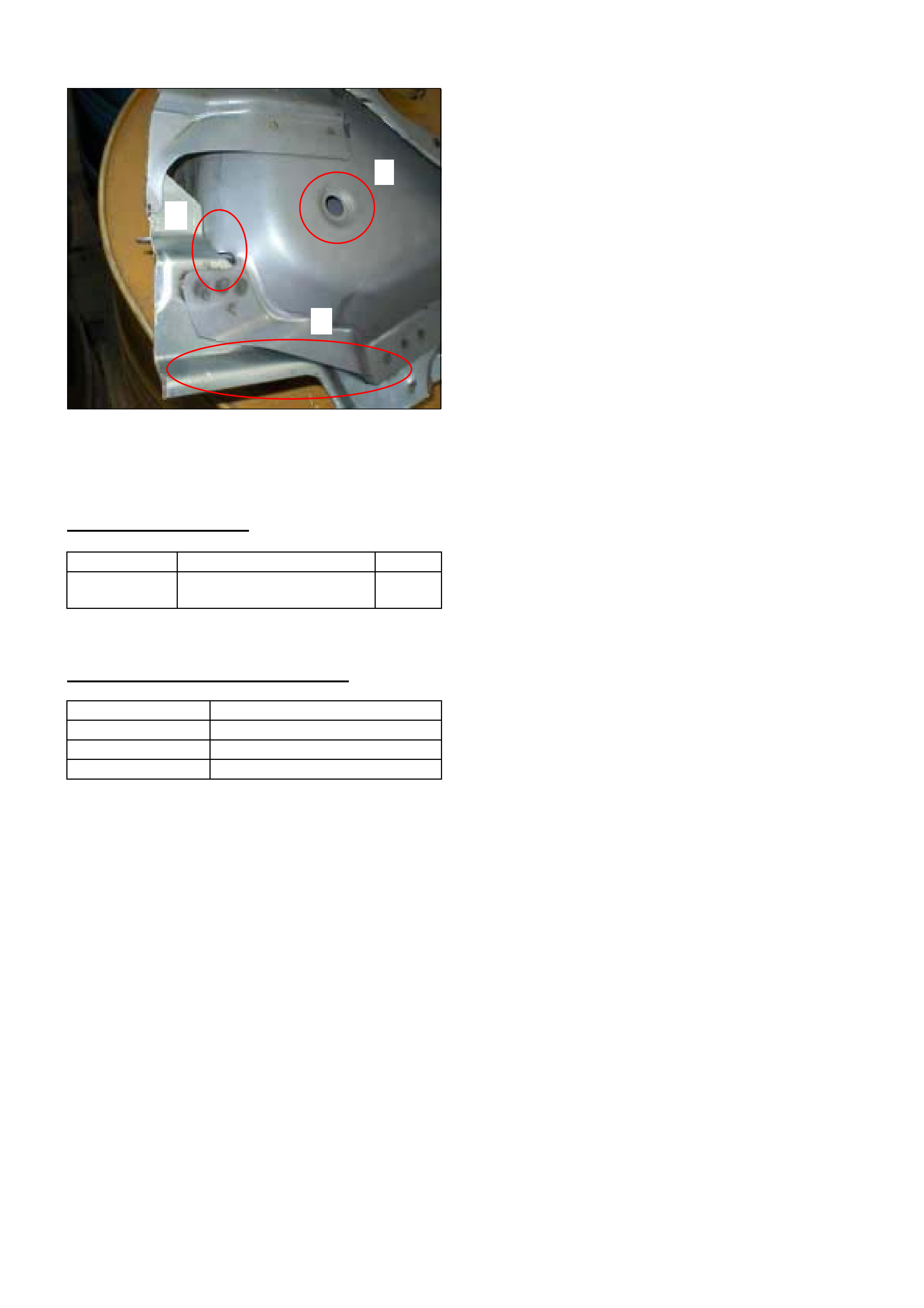
HOLDEN SERVICE TECHLINE_________________________________________________________________AUGUST, 2003
14
Figure 7. Gaps 2 and 4 are easy to reach,
whilst gap 3 is behind the drain tube.
PARTS INFORMATION
Part No.: Description: Qty:
92156600 Deadener - Rear
component lid panel
2
WARRANTY CLAIM INFORMATION
Description Dust Entry – Seal Panels
Labour Op. No. A000297
Time 1.5 hr
Failure Code 88 - Dust Leak
3
4
2

HOLDEN SERVICE TECHLINE_________________________________________________________________AUGUST, 2003
15
INFORMATION
Answering Customer Queries About Fuel
Consumption Labelling On New Vehicles
Passenger Vehicles
(GROUP OB) TL540-0308
The following information is provided to assist
frontline service staff when customers have concerns
that they are not achieving the fuel consumption
figures as shown on the label that was originally
attached to the inside of the windscreen on their new
vehicle.
• As from 1st Jan 2001 a new Australian Design
Rule (ADR 81/00) came into effect which requires
every new vehicle built to have a fuel consumption
label attached to the inside of the windscreen.
• The primary intention of the labelling is to provide
prospective new car buyers with a means of
comparing the fuel consumption of different
vehicles that have been tested to a standardised
procedure.
• The figure shown on the label is the fuel
consumption that model vehicle achieves (on
average) when tested on a dynamometer to the
City Cycle procedure of Australian Standard
AS2877 for Fuel Consumption Testing.
• An owner may experience different figures to
those on the label depending on driving habits,
driving conditions and condition of the vehicle.
A study conducted for the former Department Of
Primary Industries and Energy, found that on
average, drivers may use up to 15% more fuel than
the published figures for city cycle driving
conditions.
Please ensure that all your Sales, Service and
Predelivery staff are made aware of the above
information.
Note: Further information on this topic can be
accessed via the Holden Lionheart Portal on your
retailers PC. On the menu page, go to the section
titled “Useful Links” and select “Australian
Greenhouse Office Fuel Consumption Guide.
This will take you to the website
www.greenhouse.gov.au
SERVICE FIX
Cruise Control Returns To Set Speed
Too Rapidly
ZC Vectra with Z32SE
(GROUP 12) TL552-0308
PROBLEM DESCRIPTION
Some customers may report the following condition
which occurs whilst driving with cruise control set -
After the vehicle loses speed while driving uphill, it
then accelerates too rapidly back to the set speed.
Another customer description may be that when they
press the resume switch to return to the previously
set speed the vehicle accelerates too quickly.
SERVICE RECTIFICATION
A revised engine calibration has been developed to
address this condition and is available on TIS CD
43.1.
The new calibration can be down loaded via the
standard Service Programming System (SPS)
method.
IMPORTANT
Always ensure the latest Tech 2 software from
TIS is loaded into your Tech 2 before attempting
any reprogramming using SPS method.
WARRANTY CLAIM INFORMATION
Use Labour Times information in Warranty
Information section of current PV SIP CD.
Update
HOLDEN SERVICE TECHLINE_________________________________________________________________AUGUST, 2003
16
SERVICE FIX
Gear Shift Lever Rattle/Buzz caused by
- Knob and/or
- Remote Shifter Linkage
VTII, VX, VU, VY, V2, with Gen III M/T
(GROUP 7A) REVISED TL464A-0308
This Techline supercedes the previous one in Issue
6, 2003. It is revised by addition of a detailed rattle
diagnosis procedure and recommendations for fixing
gearshift knob rattle.
PROBLEM DESCRIPTION
During acceleration in any gear a rattle noise may be
emitted from the gear knob and shifter area. The
noise is usually more prominent when vehicle is cold.
There are two possible sources of this noise:
Gear Knob rattle: - this is a plastic rattle sound
Shifter Linkage: - this is a metallic rattle sound
SERVICE RECTIFICATION
Summary: Correctly identify the source of the rattle
(knob or shifter Linkage) and rectify as explained
below.
Gear knob rattle
Gear knob rattle can be heard during heavy
acceleration above 3000rpm in any gear. While
accelerating, twist the gear knob clockwise or anti-
clockwise then slowly release the knob – if the rattle
is reduced or eliminated – this confirms the gear
knob is rattling. This test is best done with a cold
vehicle, as it is much easier to reproduce the rattle
when cold.
When the rattle is confirmed as coming from the gear
knob, proceed as follows.
For VT/VX: Glue the gearshift knob to the lever as
described in Techline in Issue 2/2002.
For VY: Install a new gear knob and lever assembly
from HSPO. These parts have glue added internally
to stop rattles, and are identified by two white paint
dots on the metal shaft of the lever.
IMPORTANT. Gear knob rattle is more intrusive
than shifter linkage rattle. Therefore, correctly
identifying gear knob rattle and rectifying as
described above will have the greatest impact on the
condition described above.
Shifter Linkage Rattle
The shifter linkage rattle occurs mainly during heavy
acceleration in 3rd or 4th gear above 2500rpm. The
rattle is more prominent if you touch the back of the
gear knob with your finger when in 3rd gear, or when
you touch the front of the gear knob with your finger
when in 4th gear. It is recommended that this test be
done with a known non-rattling gear knob/lever fitted,
so that no confusion exists.
Once shifter linkage rattle is confirmed with a non-
rattling gear knob, contact TAS as per following
procedure for supply of a revised shifter assembly.
NOTE: These shifter assemblies have been precision
machined and fitted with anti-rattle washers.
TAS Shifter Exchange Program.
1. Your nominated TAS contact person should
ring TAS to register a case.
2. TAS will contact you when a revised shifter is
available and they will arrange to have it freighted to
your Retailership.
3. Retailer can then make a firm customer
booking to install the revised shifter.
4. Return the replaced shifter using the REPAC
return process, immediately the shifter is
removed. Do not wait for the next REPAC report!
5. Please fill out ALL details on the return
paperwork supplied with the shifter for closure of
your TAS case and to ensure no parts charge is
levied against your Service Department.
WARRANTY CLAIM INFORMATION
For vehicles repaired under warranty :
Description Replace transmission
remote shifter assembly
Labour Op. No. K000291
Time 2.7 hr
Failure Code 28 rattle
Update

HOLDEN SERVICE TECHLINE_________________________________________________________________AUGUST, 2003
17
SERVICE FIX
Holden Assist Receives Invalid Location
Information From Vehicle
VY / V2II / WK with Telematics
(GROUP 12) TL538-0308
PROBLEM DESCRIPTION
Some customers may report that Holden Assist has
advised them that invalid location information is being
received from their vehicle.
The cause for this condition has been traced to a
defect in Telematics software version 001.000.005
when subjected to low GPS signal strength.
This defect causes the Telematics module to transmit
invalid location information when the Holden Assist
button is pressed.
PRODUCTION RECTIFICATION
Software revision 001.000.010 introduced into vehicle
production to rectify this condition from:
ISOVIN: Build Date:
6G1YX54F63L137064 23/06/03
SERVICE RECTIFICATION
If a customer reports the above problem and the
vehicle is built prior to the above breakpoint, install
new software into Telematics module with Tech 2 as
per the following procedure.
IMPORTANT: The following procedure can only be
performed using Tech 2 software version 12.305
from TIS CD 43.1. (or later)
1. Access the Telematics with Tech 2. by making
the following selections:-
Model Year / Vehicle Type / F1:Body /Telematics
Module
If the Telematics module has version 001.000.005
software (old) the following screen will appear.
2. To reprogram the module return to the main
menu as shown in next screen and select “F1:
Service Programming System (SPS)”.
3. The following screen will be displayed on Tech 2.
Follow the screen prompts, and request info from the
Telematics module by selecting “F0: Request Info”.
4. Make the following selections appropriate to the
vehicle being reprogrammed.
Model Year /Vehicle Type / F1:Body / Telematics
Module
5. When prompted by Tech 2 go to your PC,
open TIS 2000 and enter the SPS application
from the main menu.
6. Follow the standard SPS prompts ensuring that all
vehicle information is correct for the vehicle you are
programming.
7. Once the programming information has been
downloaded into Tech 2 return to the vehicle and
follow the screen prompts as per the standard SPS
process.
8. When the programming process is complete,
Tech 2 will prompt to select the continue soft key, and
the following screen will be displayed.
Body
(4) 2004 WK Series
Telematics Module
Use Service Programming System (SPS) to Program this
ECU before Continuing !
Software Version Number 001.000.005
Confirm
Main Menu
F0: Diagnostics
F1: Service Programming System (SPS)
F2: View Capture Data
F3: Tool Options
F4: Download/Upload Help
Service Programming System (SPS)
Version 2.021
F0: Request Info.
ECU to be programmed must be installed before request info.
Tech 2 is ready to request data from the vehicle!
Service Programming System (SPS)
Version 2.021
F0: Request Info.
ECU to be programmed must be installed before request
info.
Tech 2 is ready to request data from the vehicle!
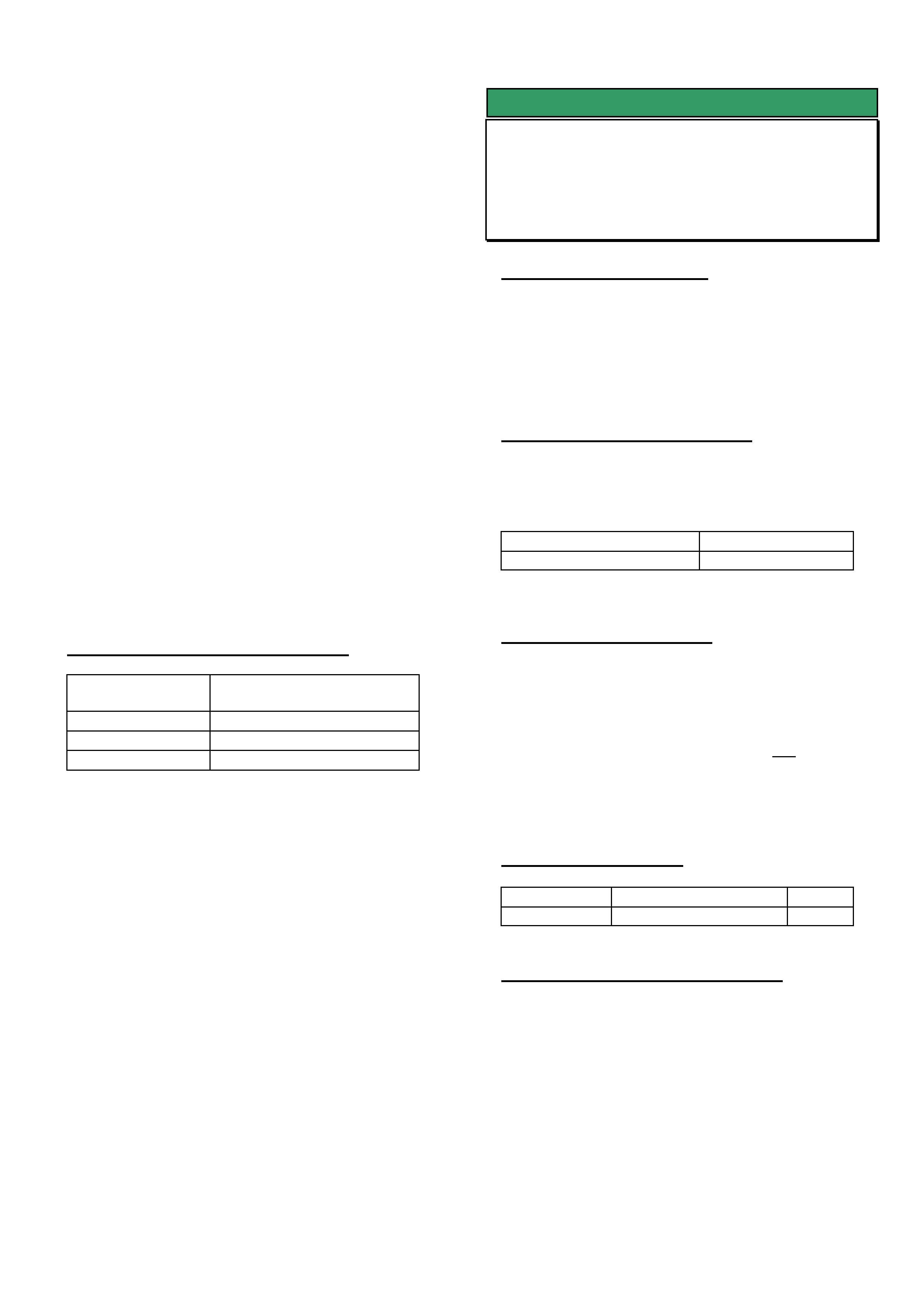
HOLDEN SERVICE TECHLINE_________________________________________________________________AUGUST, 2003
18
9. When this screen is displayed select the EXIT key
to return to the Main Menu.
10. At this stage the programming process is
complete and you will be able to communicate with
the Telematics module.
11. Using Tech 2 access the Telematics module by
making the following selections;
Model Year / Vehicle Type / F1:Body / Telematics
Module
12. Check the VIN number. If different to vehicle
VIN, you will require a Change Over module from
Australian Arrow, which can be obtained via the
standard Change Over process.
13. The Telematics module will automatically be left
in SERVICE mode after completing the programming
process.
NOTE: The vehicle should be returned to the
customer with the Telematics system in the same
operating mode as it was delivered to your
retailership. If unsure which mode the Telematics
module was in when it arrived at your retailership, it
should be left in SERVICE mode.
WARRANTY CLAIM INFORMATION
Description Reprogramming
Telematics Module
Labour Op. No. N000438
Time 0.3 hr
Failure Code 57 Registers Incorrectly
SERVICE FIX
Engine Cover to Clutch Hose Rattle
VT, VX, VU, V2 with LS1 (Gen III) V8
(GROUP 6A) TL542-0308
PROBLEM DESCRIPTION
An engine cover “rattle” may occur in vehicles built
with a plain clutch hydraulic hose and clamps (built
prior to L867194).
This hose may twist and rub against the engine
cover, creating an engine cover “rattle” noise.
PRODUCTION RECTIFICATION
A convoluted hose with ‘quick-connect’ fittings,
allowing stress-free positioning of the hose, has been
fitted in production from:
ISOVIN: Build Date:
6H8V2X37F2L867194 22/5/2002
SERVICE RECTIFICATION
Summary: Fit a new Clutch Hose Asm.
If the above condition is confirmed – replace the
existing plain hose and its two clamps with a
convoluted hose p/n 92145810. This hose is a “snap
fit” onto the existing fittings and needs NO clamps to
retain it. These “snap fit” connections allow the hose
to rotate freely to an unstressed position, clear of the
engine cover.
PARTS INFORMATION
Part No.: Description: Qty:
92145810 Hose Asm. - Clutch. 1
WARRANTY CLAIM INFORMATION
For replacement of plain clutch hose with convoluted
hose – use existing clutch hose labour operation
number and time in the current PV SIP CD.
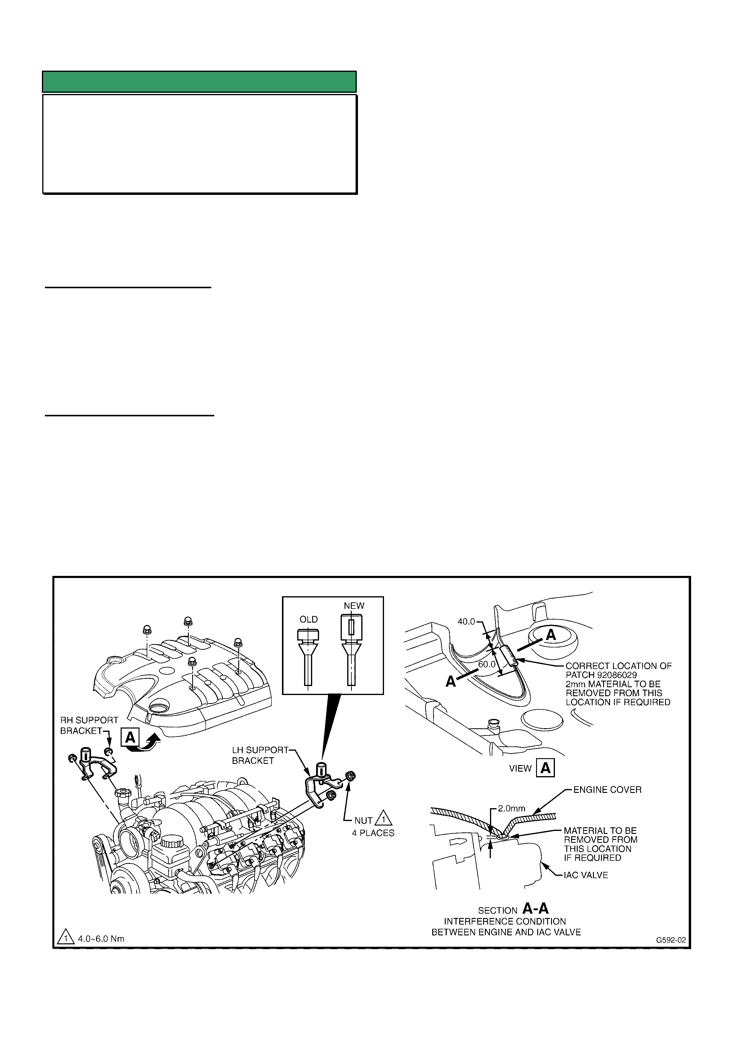
HOLDEN SERVICE TECHLINE_________________________________________________________________AUGUST, 2003
19
SERVICE FIX
Engine Cover Rattle Noise
V & W Models with LS1 (Gen III) V8
(GROUP 6A) UPDATE TL523-0308
This Techline should be used in conjunction with the
previous Techline on this topic (Issue 5, Nov. 2002),
Additional information is supplied together with a NEW
Labour Operation No. for use with both Techlines.
PROBLEM DESCRIPTION
Engine cover “rattle” at idle, or just above idle speed.
This rattle is caused by the engine cover contacting
components under the cover, or the engine cover not
being restrained firmly by the rubber bumpers on which
it is located.
SERVICE RECTIFICATION
Summary: Ensure latest type rubber bumpers are
fitted, and add four foam damper pads.
NOTE: The following procedure is condensed from the
Nov., 2002 Techline, as most engine cover rattle
complaints will have been addressed by that bulletin.
The following procedure is for complaints of “engine
cover rattle” noise on any Gen III V8:
1. Remove four engine cover retaining nuts and
remove the engine cover.
2. Ensure that foam insulator 92086029 is in
place on the engine cover in the location just above
the IAC valve as shown in Figure 1, view A. If foam
insulator is badly damaged due to contact with the
IAC valve it should be replaced. Prior to fitting new
insulator, remove 2 mm of material from the cover
as shown in Figure 1, Section A-A. NOTE: Engine
covers (p/n 92091015) with increased clearance to
IAC valve were fitted to vehicles from: Tag No.
L794821 Build Date 8/11/01.
3. Ensure the “new” design bumpers are
fitted – as per Figure 1 below.
4. Fit four self adhesive foam pads, 92087589 to
underside of engine cover in locations as shown in
Figure 2 below, locations A, B, C, D. To fit the pads,
remove the protective film from the adhesive side of
the foam pad.
5. Re-fit engine cover. Ensure that the cover
does not contact surrounding parts such as engine
oil level indicator, engine and power steering filler
caps and clutch master cylinder hose. (see
separate Techline bulletin regarding Engine Cover
to Clutch Hose “Rattle”).
Fit and Torque the four engine cover retaining nuts to
8-12Nm.
Figure 1.
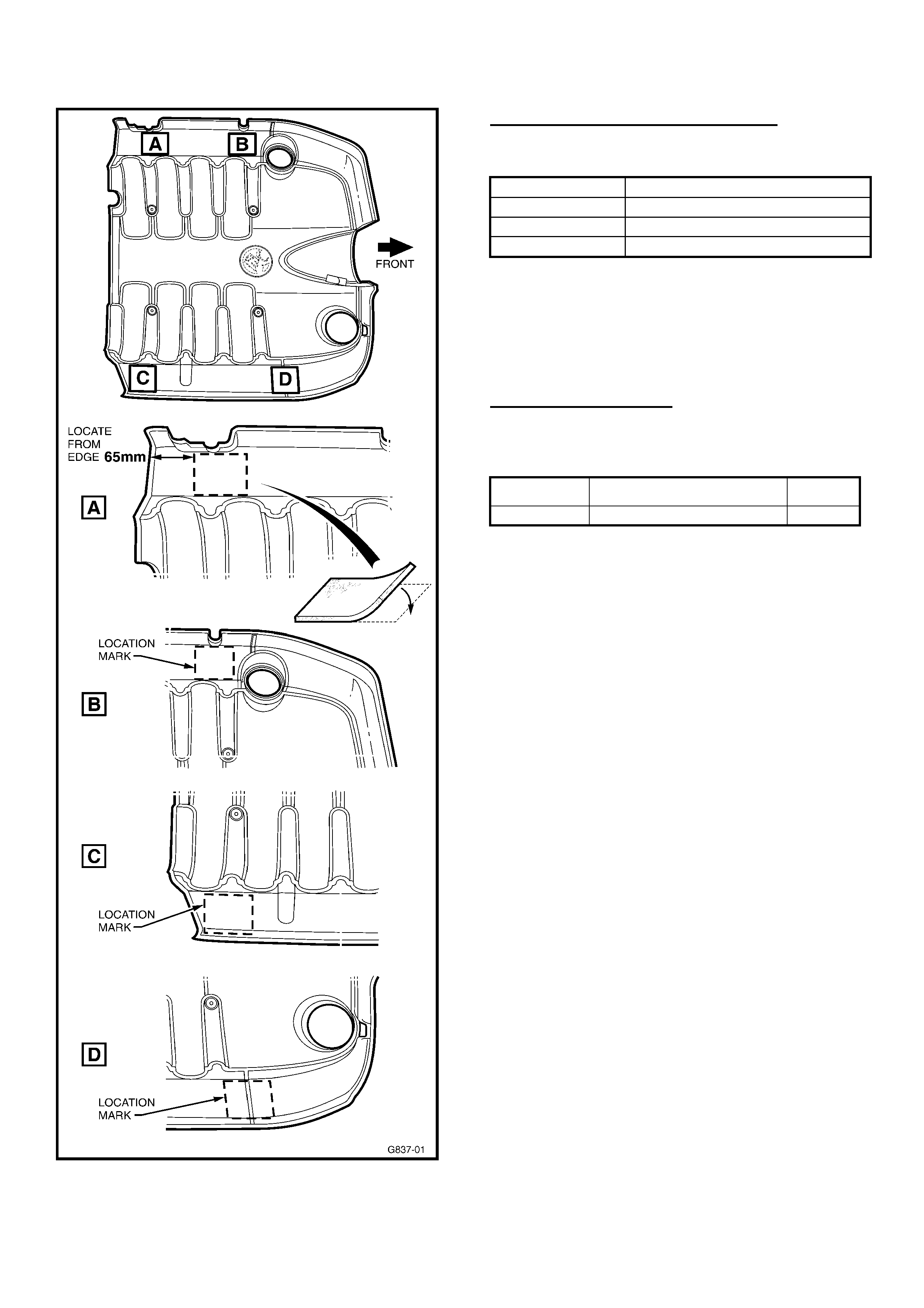
HOLDEN SERVICE TECHLINE_________________________________________________________________AUGUST, 2003
20
Figure 2 – Underside of Engine Cover.
WARRANTY CLAIM INFORMATION:
Use the following information:
Description Fit Engine Cover Rattle Fix Parts
Labour Op. No. J000725
Time 0.3 hr
Failure Code 28 (Rattle)
NOTE: the above Labour Operation No. replaces the
previously used Labour Operation No. J000651 as
given in previous Techline on this topic (Issue 5, Nov.
2002). J000651 can no longer be used.
PARTS INFORMATION
In addition to the parts quoted in the Nov., 2002
Techline, use:
Part No.: Description: Qty
92087589 Damper, Engine Cover 4
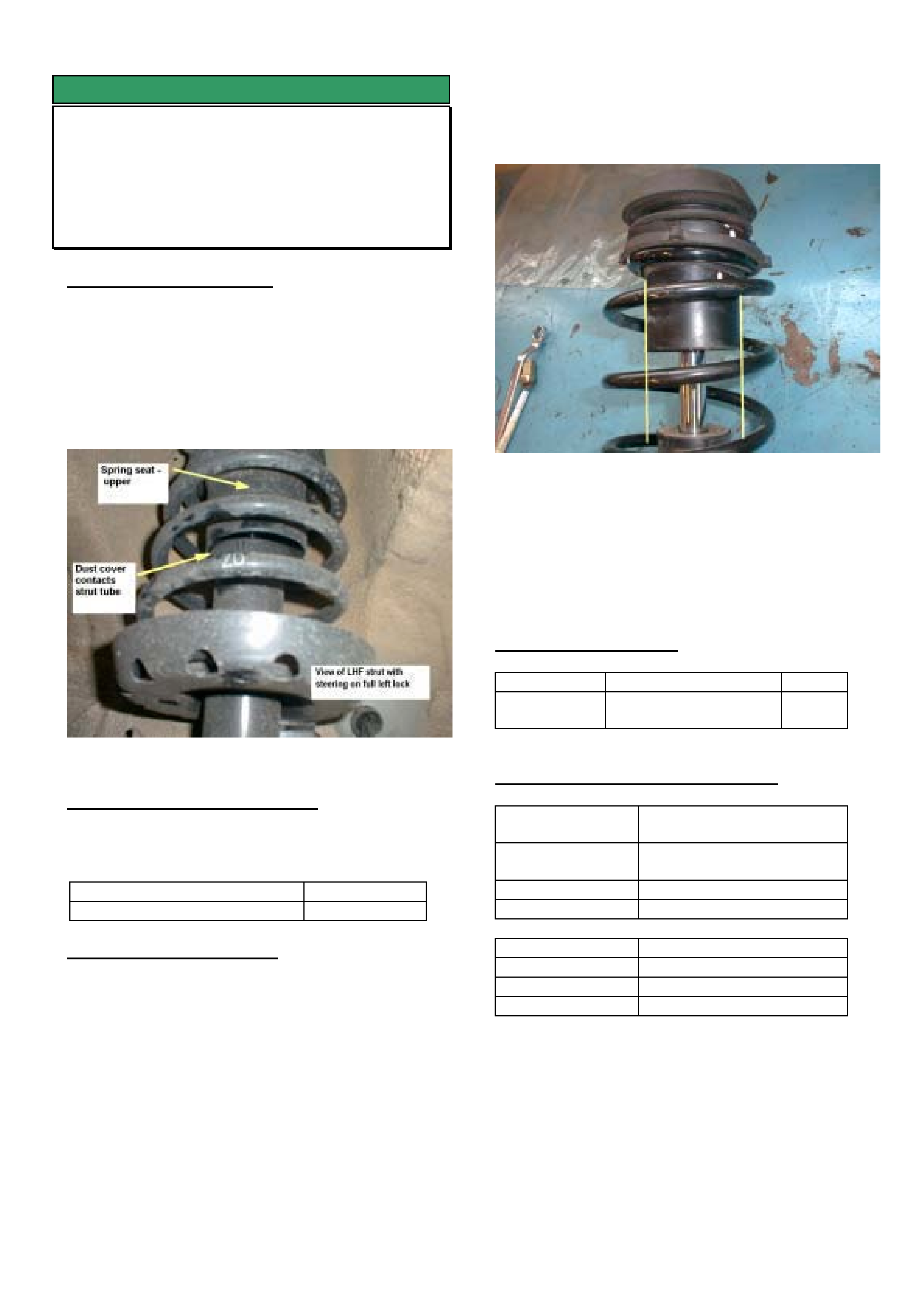
HOLDEN SERVICE TECHLINE______________________________________________________________SEPTEMBER, 2003
6
SERVICE FIX
Front Suspension Noisy – Strut Dust
Cover Fouls On Strut Tube
TS Astra
(GROUP 3) TL560-0309
PROBLEM DESCRIPTION
The dust cover section of the upper spring seat
contacts the strut tube, making a scraping noise over
bumps.
The cause of this condition is misalignment of the
upper front spring seat during assembly.
Figure 1 shows the condition.
Figure 1
PRODUCTION RECTIFICATION
Upper spring seat revised to eliminate misalignment
during assembly on vehicles from.
ISOVIN: Build Date:
W0L0TGF4835227725 10/06/03
SERVICE RECTIFICATION
Summary: Re-align upper spring seat as per following
procedure.
1. Inspect the dust cover.
2. If cover is undamaged, go to step 3.
NOTE: If the dust cover is damaged, the spring seat
upper should be replaced. Replace as per TIS and
ensure correct alignment is achieved as follows.
3. Remove strut from the vehicle as per TIS.
4. Use a spring compressor to relieve the tension on
the spring as per TIS.
5. Once the tension on the spring is relieved, the
upper spring seat (including dust boot) will be
able to be rotated so that the dust cover is parallel
to the strut tube as shown in figure 2.
Figure 2
6. Release spring compressor and re-install strut
into vehicle as per TIS.
7. Perform a wheel alignment on the vehicle.
PARTS INFORMATION
Part No.: Description: Qty:
90468618 Seat-front spring,
upper
1
WARRANTY CLAIM INFORMATION
Description Boot/Bumper, piston rod-
Replace
Labour Op. No. E130210 (RHS), or
E130220 (LHS)
Time 0.9 hr
Failure Code 25 misaligned
Description Wheel Alignment
Labour Op. No. P201120
Time 0.7 hr
Failure Code
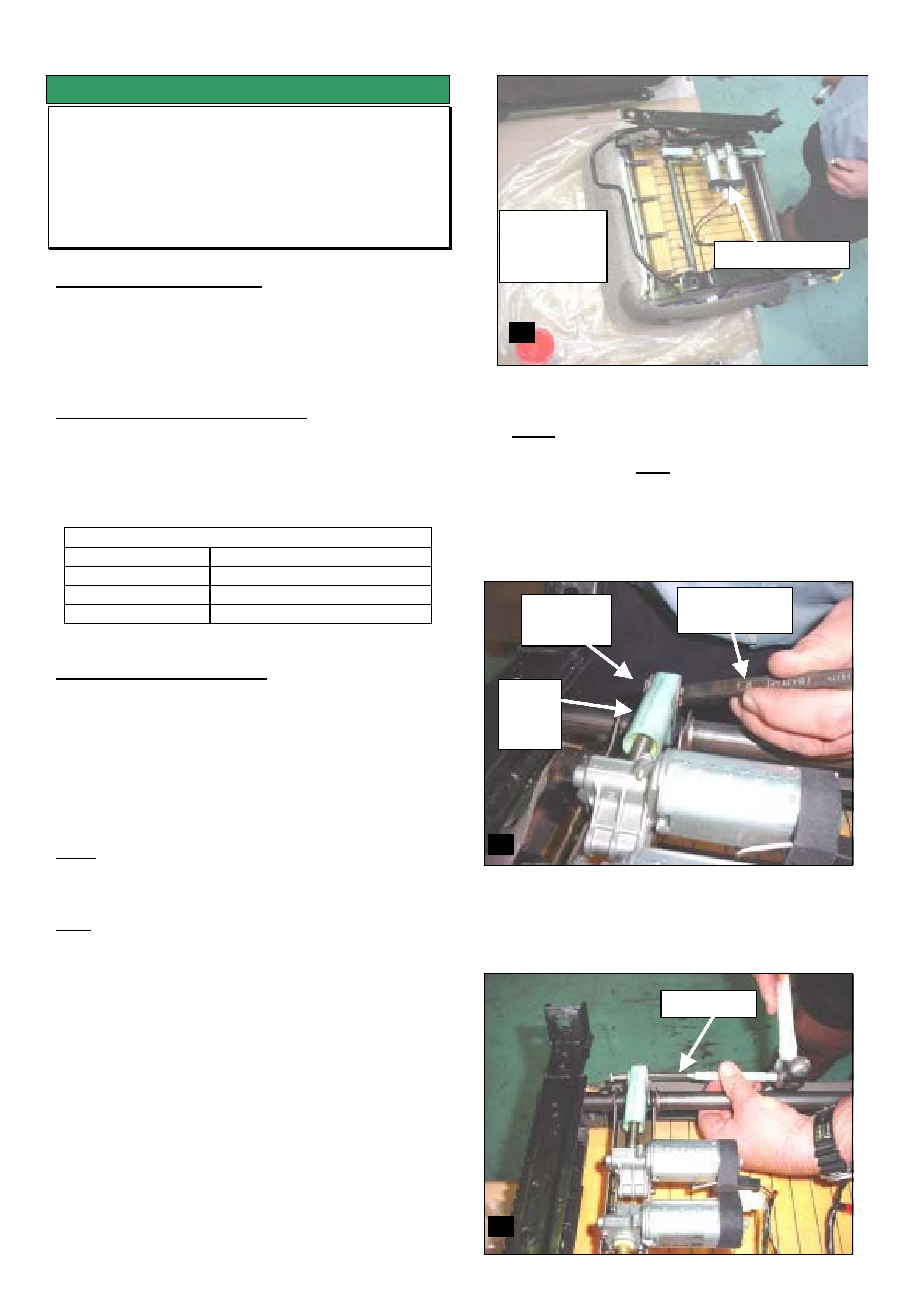
HOLDEN SERVICE TECHLINE______________________________________________________________SEPTEMBER, 2003
7
SERVICE FIX
Seat Height Adjuster Inoperative –
Disengaged Thread
VX, VY, V2, VU & WH
(GROUP 01) TL537-0309
PROBLEM DESCRIPTION
The seat height adjuster becomes inoperative due to
the adjusting shaft dislodging from the clevis (plastic
type). NOTE. The plastic clevis nut was introduced into
seats in mid 2000.
PRODUCTION RECTIFICATION
A new seat base assembly featuring a metal clevis nut
was introduced from the breakpoints shown below.
The new seat base is currently not interchangeable with
the pre B/P seat base.
Vehicle Breakpoints:
VY 31/3/03
WK Start of production
VY ute 20/5/03
V2 Series III Start of production
SERVICE RECTIFICATION
Install the metal clevis nut to seat if the plastic clevis
nut has failed as per following procedure.
1. Operate the seat height adjustment to the highest
upward position.
2. Remove the seat assembly refer to the appropriate
section of SIP if required.
Note: Be careful not to scratch any interior trims when
removing and installing the seat, use a guard cover to
protect the trims if required.
Note: Pay special attention to the instructions for the
deactivation of the side air bags (if fitted)
3. Cover a cleaned workbench with a clean soft cloth
or clean cardboard to avoid damage to the seat
cushion material. Refer diagram 1.1.
4. Place the seat on the workbench with the cushion
facing downwards. Add a piece of cardboard or rag
on the seat cushion under the seat drive motor to
aid in retrieving any parts that might fall.
5. Locate the Clevis nut located on the seat track
mechanism (refer diagram 1.2). Using a small
sharp cold chisel, shear off the Clevis nut retaining
pin “staking” (refer diagram 1.2) on both sides of
the retaining pin. Note: You many have to turn the
retaining pin to access the staking on the underside
of the pin. Using a small flat blade screwdriver “pry”
the locking tab for the retaining pin away from the
pin square head. The retaining pin can now be
turned using a 10mm open spanner.
6. Once the Retaining pin “staking” has been
removed, knock the pin through the mounting
bracket using a suitable pin punch and hammer.
Refer diagram 1.3
Clean
protective
covering Drive motors
1.1
Nylon
Clevi
s nut
Retaining
pin
Small sharp
cold chisel
1.2
1.3
Pin Punch
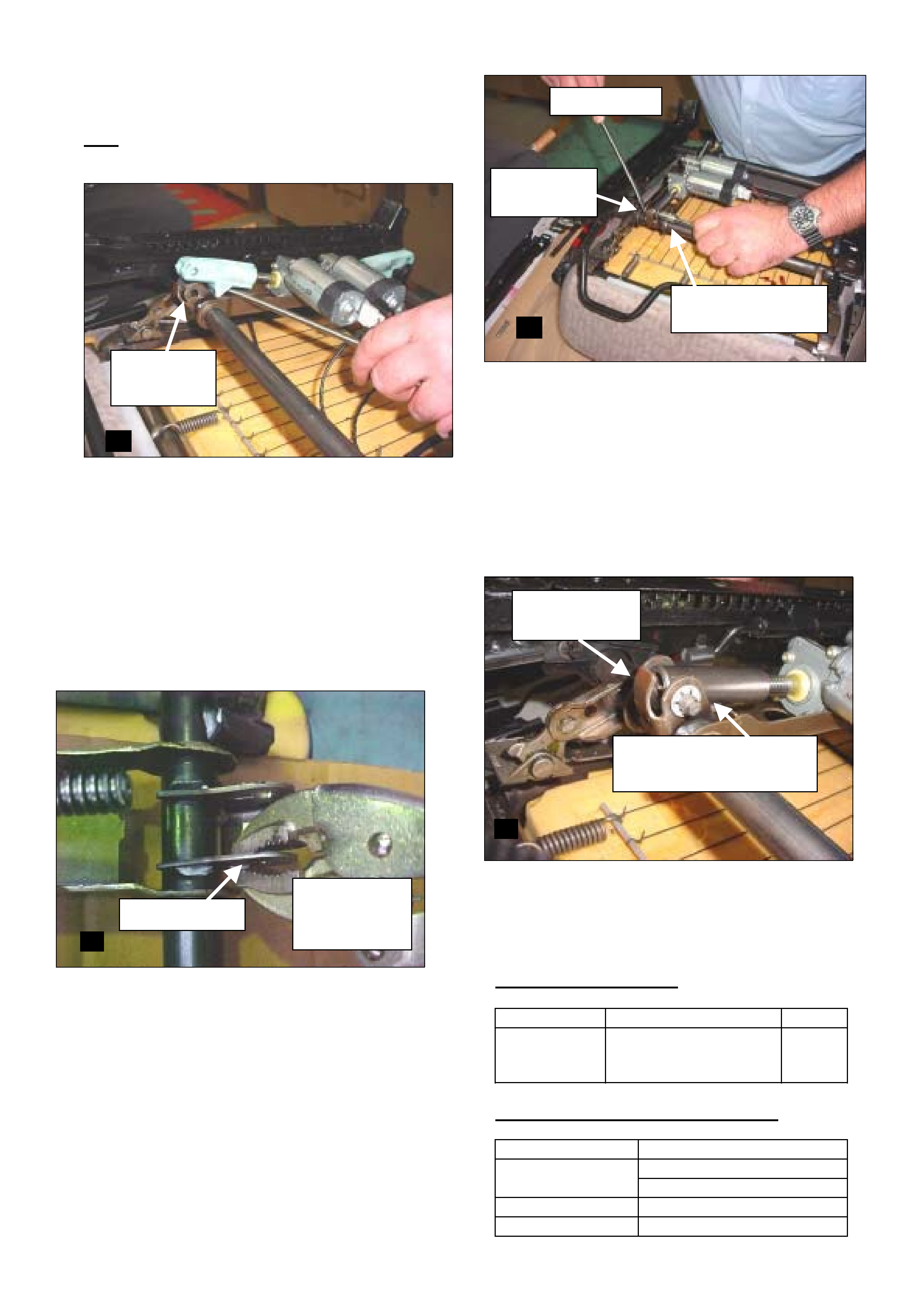
HOLDEN SERVICE TECHLINE______________________________________________________________SEPTEMBER, 2003
8
7. Using a flat blade screwdriver “pry” the Clevis nut
out of the mounting on the seat track.
Note: Avoid damaging the Clevis bracket tab. Refer
to diagram 1.5.
8. Unscrew / remove the Clevis nut from the electric
seat motor spindle in an anti-clockwise direction.
9. Grease the electric seat motor spindle and Clevis
pivot hole with High Temperature / Pressure
Grease.
10. Using Vise grips flatten the retaining pin locking
tab, on the inner of the bracket only, to allow later
assembly of the 8mm internal locking star washer
(Refer to diagram 1.5)
11. Screw the new metal (service pack) Clevis nut ½
way onto the electric seat motor spindle.
12. Place the Clevis nut into the mounting bracket with
the stop plate facing downwards towards the seat
cushion (refer to diagram 1.7). Move the retaining
pin mounting (pivots) until the Clevis nut pivot hole
lines up.
13. Insert the new retaining pin (service pack) through
the Clevis nut mounting (refer diagram 1.6 for pin
fitment direction). Move the retaining pin locking tab
(moved away at step 5) into a position to lock the
square head of the retaining pin.
14. Support the retaining pin head with the end of a flat
blade screwdriver (refer to diagram 1.6). Fit the
retaining pin 8mm internal locking star washer
(from service pack) over the retaining pin end.
Using a 10mm extra deep socket and your hand
push the locking washer all the way towards the
Clevis nut mounting face. Refer to diagram 1.6.
15. If the Clevis bracket tab was bent during initial
retaining pin removal gently tap it back into position
using a hammer. Refer to diagram 1.7.
16. Following steps 5 through 15 replacing the other
Nylon Clevis nut.
17. Refit the seat to the vehicle as described SIP.
PARTS INFORMATION
Part No.: Description: Qty:
92147358 Kit Clevis Nut
(One kit does one
seat)
1
WARRANTY CLAIM INFORMATION
Description Clevis Nut Kit
C000493 - RHF
Labour Op. No. C000496 - LHF
Time 1.0 hr
Failure Code 07 Stripped
Limiting stop plate facing
towards cushion
1.7
Clevis bracket
tab
1.5
Locking tab
Retaining pin
locking
washer side
1.6
Screwdriver
10mm Extra deep
socket
Pin fitment
direction
Clevis nut
mounting
1.4
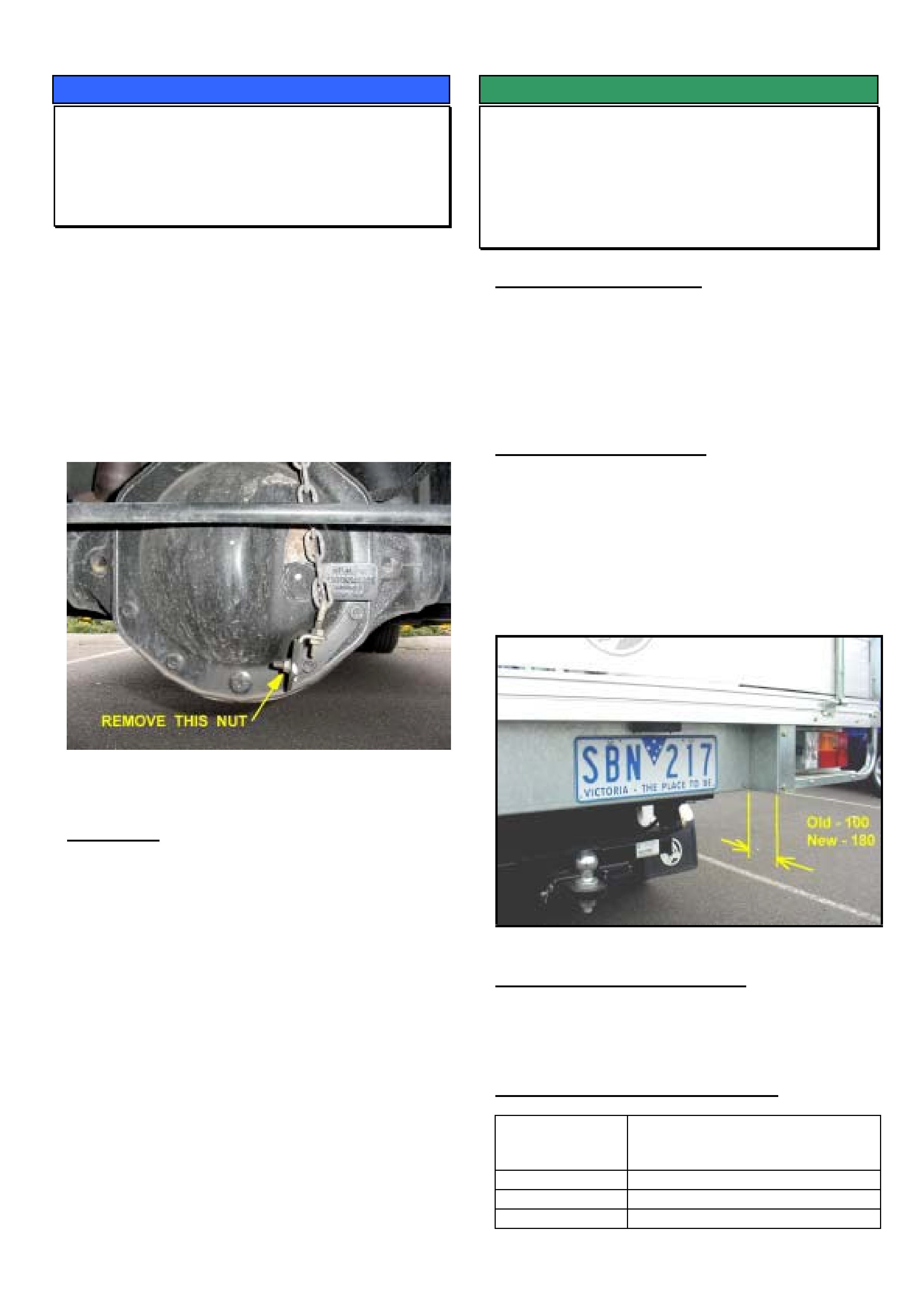
HOLDEN SERVICE TECHLINE______________________________________________________________SEPTEMBER, 2003
9
SERVICE PROCEDURE
Access To Differential Oil Filler Plug
VY Regular Cab
(GROUP 4) TL554-0309
If difficulty is experienced in accessing the differential
oil plug due to the location of the Load Sensing Valve
(LSV) chain, the following procedure is
recommended to access the plug.
• Remove the nut which attaches the LSV chain
bracket to the Diff. housing bracket and swing the
bracket with chain attached out of the way.
The following photograph shows the nut to be
removed.
• When reattaching the chain bracket, torque the
attaching nut to 5 – 8 Nm.
IMPORTANT:
1. DO NOT bend the chain to gain access to the
plug
2. DO NOT remove the chain adjuster from its
bracket.
Either of these actions may alter the adjustment of
the load sensing valve.
SERVICE FIX
Insufficient Clearance Between Tow Ball
And Number Plate Support
VY Regular Cab fitted with Triple M tray
(GROUP 1) TL558-0309
PROBLEM DESCRIPTION
On some vehicles fitted with a Holden towbar and
Holden endorsed Triple M tray (manufactured prior to
mid August 03) there is insufficient clearance between
the tow ball and the number plate support. This may
result in the tow bar hitch fouling the number plate
support.
SERVICE RECTIFICATION
If you have a vehicle with the above condition, contact
Triple M Holdings P/L on freephone 1800 773 030 to
obtain two longer number plate support mounting
brackets and mounting bolts.
The effect of fitting these longer brackets is that the
number plate support member is moved towards the
front of the vehicle by 80mm thereby eliminating the
above condition. Refer photograph below.
PRODUCTION RECTIFICATION
The above condition was rectified on Holden
endorsed Triple M trays from mid August by fitting the
longer (180mm) number plate support brackets.
WARRANTY CLAIM INFORMATION
Description Fit revised number plate support
brackets to Triple M tray – both
sides
Labour Op. No. R000112
Time 0.4 hr
Failure Code 62 Improper clearance
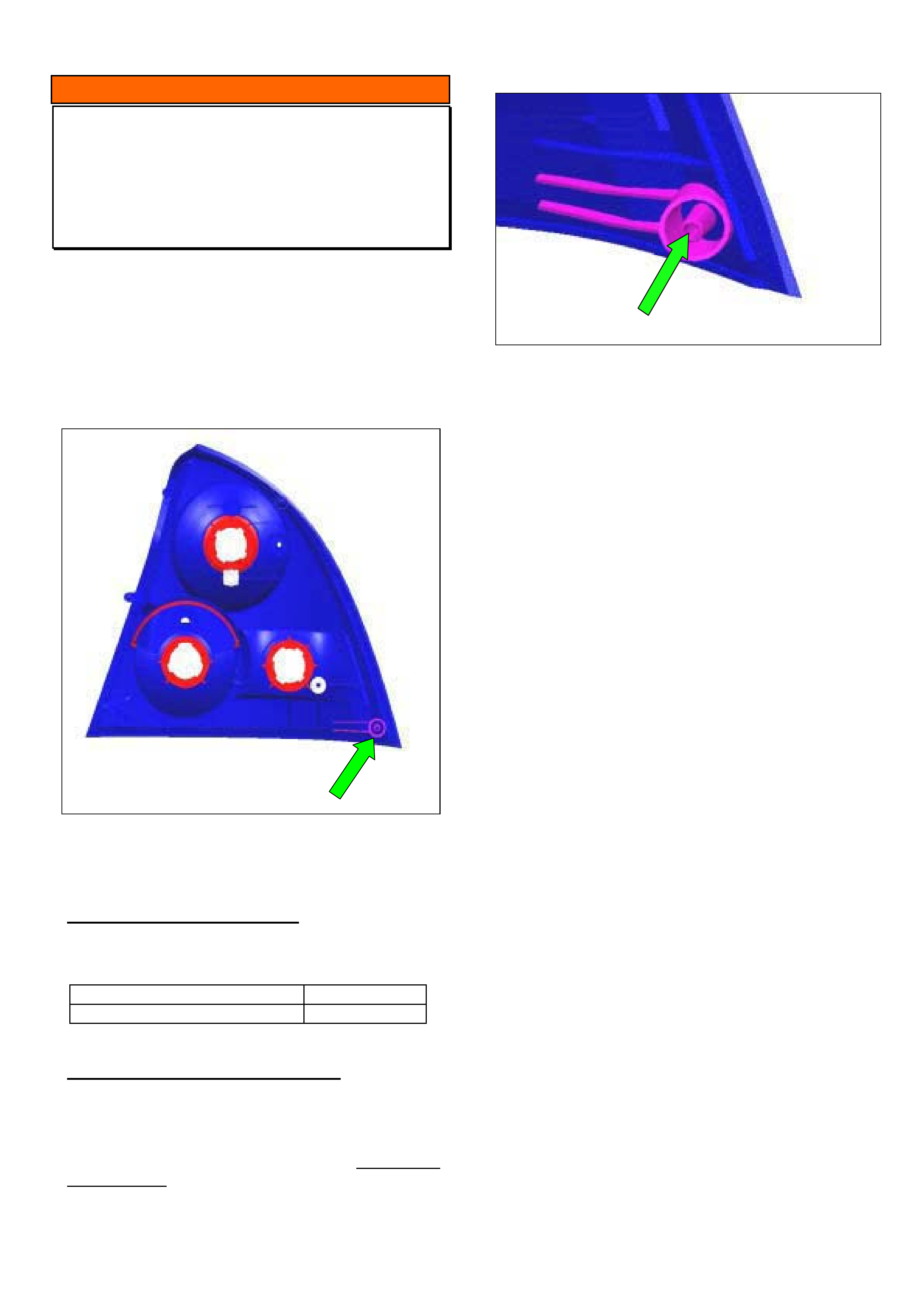
HOLDEN SERVICE TECHLINE______________________________________________________________SEPTEMBER, 2003
10
INFORMATION
Tail Lamps Revised – Additional Datum
Pin
VY Sedan
(GROUP 12) TL551-0309
The tail lamp housing has been modified as follows
to improve fitment of the tail lamp during vehicle
assembly.
♦ A second datum pin has been added to the lower
section of the housing. NOTE; a matching hole
for this datum pin has been added to the rear
quarter panel.
Figure 1. Rear of tail lamp showing position of 2nd
datum pin
PRODUCTION BREAKPOINT
Tail lamps with the additional datum pin have been
fitted to vehicles from:
ISOVIN: Build Date:
* * * * * * * * * * L150811 22/07/03
SERVICE REPLACEMENT LAMPS
All replacement tail lamps supplied from HSPO will
have the second datum pin as described above.
When fitting a new tail lamp to a vehicle built prior to
the breakpoint the 2nd datum pin on the new tail lamp
assembly will need to be removed. This can be done
using a pair of side cutters. Figure 2 shows pin after
removal.
Figure 2. Shows datum pin cut off flush with the
outer ring
When fitting a new tail lamp to a vehicle built after the
breakpoint the datum pin does not need to be
removed.
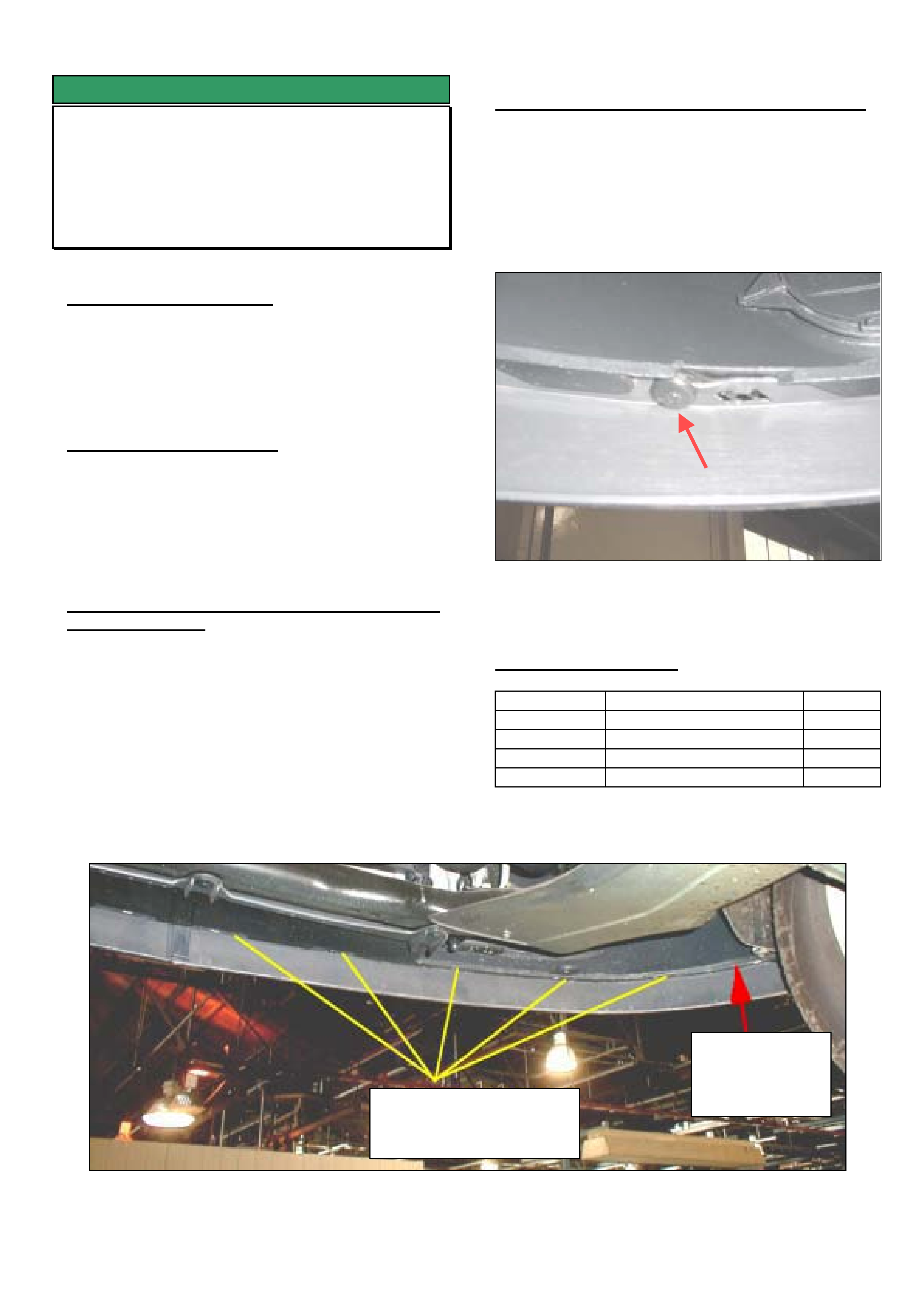
HOLDEN SERVICE TECHLINE______________________________________________________________SEPTEMBER, 2003
11
SERVICE FIX
Front Bumper Extension (Skirt) Loose or
Detached
XC, TS, TT
(GROUP 1) TL544-0309
PROBLEM DESCRIPTION
Front bumper extension (lower rubber skirt) dislodges
from the bumper fascia.
This condition is a result of the extension coming into
contact with obstacles such as concrete parking
barriers, steep driveways etc.
SERVICE RECTIFICATION
Summary: For those customers who frequently
dislodge the front bumper extension as described
above, it is recommended to add additional fastening
to the new extension as per the following procedure.
For TT models only. - Remove front brake air ducts
from both sides before commencing.
Step 1. - Add screw and nut at either end of
bumper extension.
1a. Drill a 5 mm hole through the bumper
extension and fascia at location shown in Fig 1
approx 60mm from end of extension. (To avoid
slipping of the drill bit, drill a 2mm pilot hole
first.)
1b. Insert screw 92138639 upward through hole
and tighten with nut 92138265.
1c. Repeat for other side of car.
Step 2. - Install plastic rivets to bumper extension.
2a. Drill an 8mm hole adjacent to each of the
normal attaching points as shown in Figures 1
and 2. (To avoid slipping of the drill bit, drill a
2mm pilot hole first.)
2b. Insert rivets 90087290 upward through the
8mm holes as shown in Figure 2.
Figure 2. Shows a plastic rivet installed next to the
normal skirt attaching lug.
PARTS INFORMATION
Part No.: Description: Qty:
ref Partfinder Extension - XC, TS, TT
92138639 Screw 2/car
92138265 Nut 2/car
90087290 Rivet 10/car
Figure 1. Shows location of plastic rivets and screw on RHS half. - (Same for LHS)
LOCATE PLASTIC RIVETS
ADJACENT TO NORMAL
ATTACHMENT POINTS
LOCATE SCREW
APPROX 60mm
FROM END OF
FASCIA

HOLDEN SERVICE TECHLINE______________________________________________________________SEPTEMBER, 2003
12
SERVICE FIX
Power Steering Rack Bellows Heat
Affected
V & W with Gen III engine
(GROUP 9) TL415-0309
PROBLEM DESCRIPTION
On some vehicles the steering rack bellows may be
affected by excessive radiated heat from the exhaust
system. HSV vehicles which feature extractor
systems may be more prone to this condition.
To address this condition new bellows containing
silicone are now available as a service replacement
part.
SERVICE RECTIFICATION
On vehicles where one or both bellows have been
affected by heat, install two new bellows part number
92146712.
Refer to PV SIP CD for procedure on bellows
replacement.
PARTS INFORMATION
Obtain the following parts from HSPO.
Part No.: Description: Qty:
92146712 Bellows Tie rod 1
WARRANTY CLAIM INFORMATION
For vehicles repaired under warranty use Labour
Times information in Warranty Information section of
current PV SIP CD
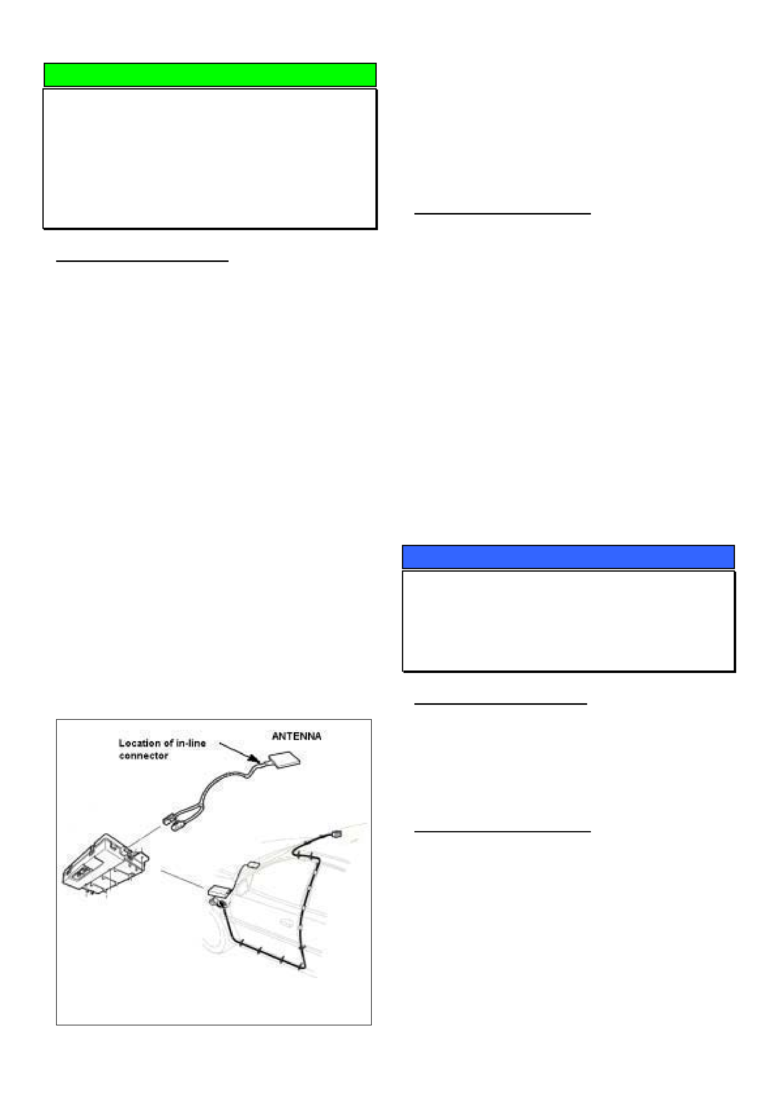
HOLDEN SERVICE TECHLINE______________________________________________________________SEPTEMBER, 2003
13
DIAGNOSIS HINT
Holden Assist Receives Invalid Location
Information From Vehicle – Summary of
Causes
VY / V2II / WK with Telematics
(GROUP 12) TL563-0310
PROBLEM DESCRIPTION
Some customers may report that Holden Assist has
advised them that invalid location information is being
received from their vehicle.
There are three known possible causes for this
problem as described below.
Cause #1 - Software
This condition has been traced to a defect in
Telematics software version 001.000.005 when
subjected to low GPS signal strength. This defect
causes the Telematics module to transmit invalid
location information when the Holden Assist button is
pressed.
Cause #2 – Connector disconnected
The Telematics antenna has two functions, one
function is to send and receive GSM (digital phone)
signals, the other is to receive the GPS (satellite)
signal.
In the Telematics system there is a remote lead
which connects the Telematics antenna to the
Telematics module. Located near the antenna end of
this lead is an in-line connector (taped over) as shown
in Figure 1.
On some Telematics antenna’s this in-line connector
has become disconnected causing the Telematics
antenna to be separated from the Telematics module.
Figure 1
Cause #3 – Terminal Crimping
At the Telematics module end of the Telematics
antenna lead there is a terminal, which is crimped on
to the coaxial cable. During the manufacture of this
lead the terminal in some instances has been over
crimped causing a short between the centre core and
the outer shield of the coaxial cable.
SERVICE RECTIFICATION
Cause #1
Follow Techline issue 8 page number 17.
Cause #2 & Cause #3
The most effective diagnosis for both of these
problems is to plug a new antenna into the Telematics
module, this should be done prior to disassembling
the vehicle to confirm the Telematics antenna is at
fault.
Note: Once the Telematics antenna is connected
allow up to1.5 hours to gain a location. Location
information can be displayed using Tech 2 referring to
the GPS data list.
If location information is still not displayed on Tech 2,
a nominated contact should contact Technical
Assistance (TAS).
SERVICE PROCEDURE
Reflash Procedure Precaution
TS & XC with Z18XE Engine
(GROUP 6C) TL569-0309
PROBLEM DESCRIPTION
Following reflashing/reprogramming an ECU in a
Z18XE engined vehicle, Diagnostic Trouble Codes
(DTC’s) relating to the Electronic Throttle Control
(ETC) may be set and driveability issues may be
experienced.
SERVICE RECTIFICATION
Following reflash/recalibration:
1. Key Ignition OFF for 10+ seconds;
2. Key Ignition ON (engine NOT started) for an
additional 10+ seconds.
These steps allow sufficient time for the ETC to
perform self-tests and relearn its default positions.
If these steps are not followed – and DTC’s set or
driveability issues are experienced, - turn the engine
OFF and perform the steps 1 & 2 above, then with
Tech-2 – proceed to clear all DTC’s stored in the ECU
and TCM.

HOLDEN SERVICE TECHLINE______________________________________________________________SEPTEMBER, 2003
14
SERVICE FIX
Cruise Control Accelerates To Set Speed
Too Rapidly
ZC Vectra with Z32SE (Except Automatic
Transmission part number 09186327 JA)
(GROUP 12) REVISED TL552A-0309
This Techline supercedes the previous one in Issue 8,
Aug 2003. It has been revised to inform that the fix
calibration is not available for vehicles fitted with part
number 09186327 JA automatic transmission.
PROBLEM DESCRIPTION
Some customers may report that with the cruise
control set - after the vehicle loses speed while driving
uphill, it then accelerates too rapidly back to the set
speed.
Another customer description may be that when they
press the resume switch to return to the previously set
speed the vehicle accelerates too quickly.
SERVICE RECTIFICATION
A revised engine calibration has been developed to
address this condition and is available on TIS CD
43.1. NOTE; this calibration is not available for
automatic transmissions part number 09186327 JA
The new calibration can be down loaded via the
standard Service Programming System (SPS)
method.
IMPORTANT
Always ensure the latest Tech 2 software from TIS
is loaded into your Tech 2 before attempting any
reprogramming using SPS method.
WARRANTY CLAIM INFORMATION
Use Labour Times information in Warranty
Information section of current PV SIP CD.
SERVICE FIX
Low Steering Assist (Intermittent)
VTII / VX / WH with Variotronic Power
Steering Option NV7
(GROUP 12) TL462-0309
PROBLEM DESCRIPTION
Some customers may complain that, intermittently,
the effort required to operate their steering increases
immediately after starting their vehicle.
SERVICE RECTIFICATION
When a customer presents their vehicle with the
above complaint the following steps should be
performed in sequence.
Step 1. Inspect the following wiring for terminal
retention and open circuits;
a. Circuits number 3 from the battery to fuse 15
and circuit number 139 from fuse 15 to the
steering solenoid YE58.
b. Circuits number 556 from connector YE58
steering solenoid to connector YB175, terminal
4 of the BCM.
c. The BCM power supplies from circuit number
740 from fuse 31 to terminal 5 YB176 and circuit
number 39 from fuse 14 to terminal 20 YB175
d. The BCM earth circuit number 155 from terminal
1 YB176 to earth point 3 and circuit number 151
from terminal 10 YB174 to earth point 3.
Step 2. Ensure that the slip ring is located
correctly on the ignition barrel and that it is making a
good connection with the key when it’s inserted into
the barrel.
Step 3. If no faults are detected during the
above checks, order a revised BCM and 2 remote
keys from HSPO. NOTE; BCMs and remotes to
rectify this condition were previously only obtainable
from Australian Arrow via TAS.
PARTS INFORMATION
Refer to latest Partfinder for part numbers of BCMs
and remote keys.
WARRANTY CLAIM INFORMATION
Description R&R BCM & program 2
keys - Variotronic Fix
Labour Op. No. N000441
Time 0.8hr
Failure Code 60 Calibration Incorrect
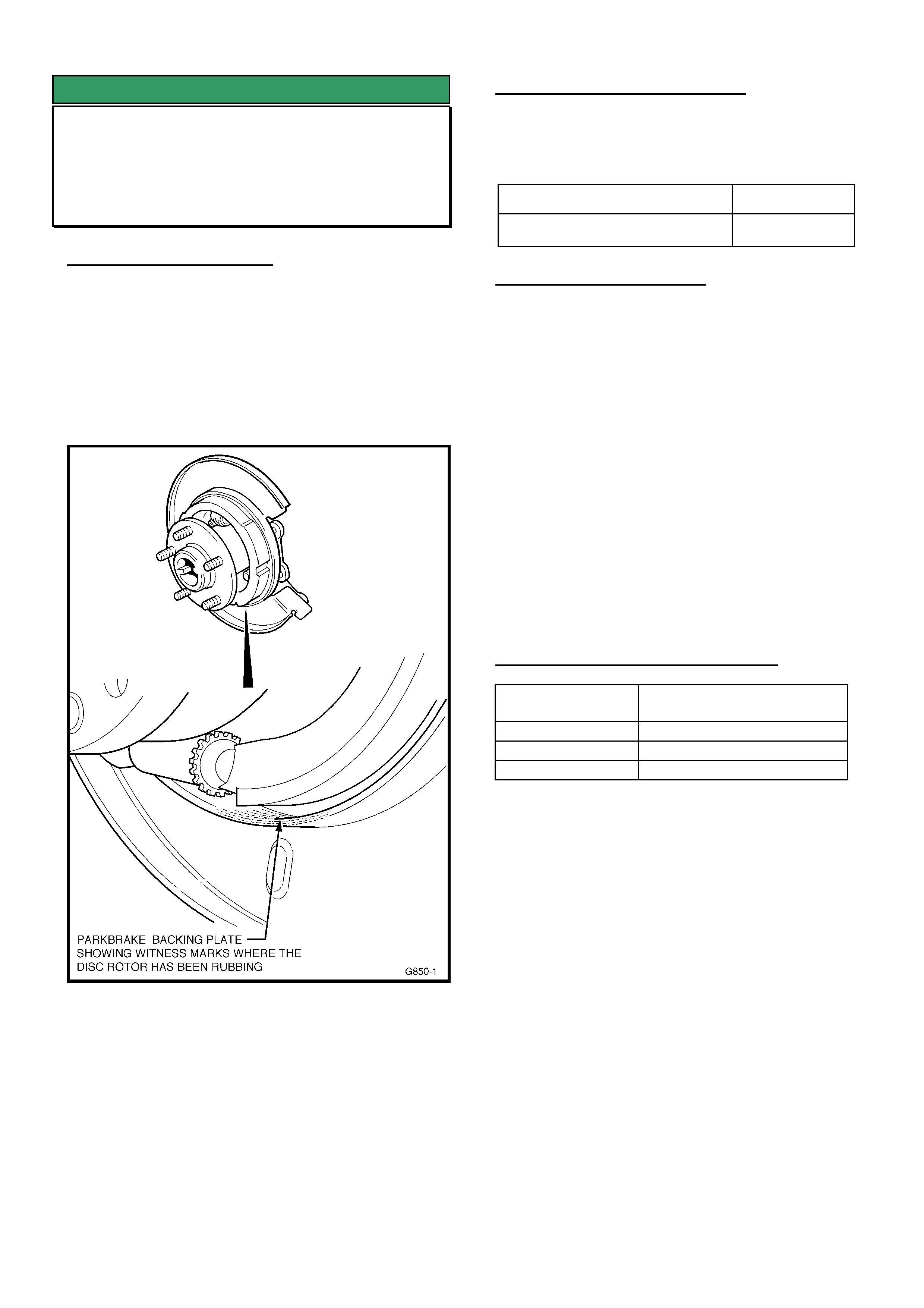
HOLDEN SERVICE TECHLINE______________________________________________________________SEPTEMBER, 2003
15
SERVICE FIX
Rear Disc Brake Scraping Noise
VY Regular Cab
(GROUP 4 & 5) TL555-0309
PROBLEM DESCRIPTION
Some vehicles may experience a scraping noise from
the rear brakes when loaded, cornering or travelling
over bumps at low speed.
Investigations show this noise is caused by the disc
brake rotor scraping on the backing plate sealing
flange, because of insufficient clearance. Figure 1
below shows the exact contact area.
Figure 1 – Showing typical rear backing plate “scrape”
marks on the sealing flange - with disc brake rotor
removed
PRODUCTION RECTIFICATION
Revised rear axle assemblies with increased
clearance between rotor and backing plate have been
fitted to vehicles from:
ISOVIN No.: Build Date:
6G1YK03A33L167677 02/09/03
SERVICE RECTIFICATION
Summary: Replace Axle assembly.
• For any vehicle with the above condition:
Replace the rear axle assembly with a new
changeover unit from DANA. (Refer to the SIP CD
VY “Special Warranty Component Replacement
Requirements” section).
NOTE: When requesting an exchange axle unit –
ensure the description “Disc Brake Scraping” is
shown on the request.
Use the standard procedure as outlined in SIP for
replacing the rear axle assembly.
IMPORTANT:
DO NOT attempt to rectify the above condition by
machining the brake rotor in the area that contacts the
backing plate.
WARRANTY CLAIM INFORMATION
Description Rear Axle Asm. –
Replace for Disc Scrape
Labour Op. No. F000191
Time 2.1 hr
Failure Code 31
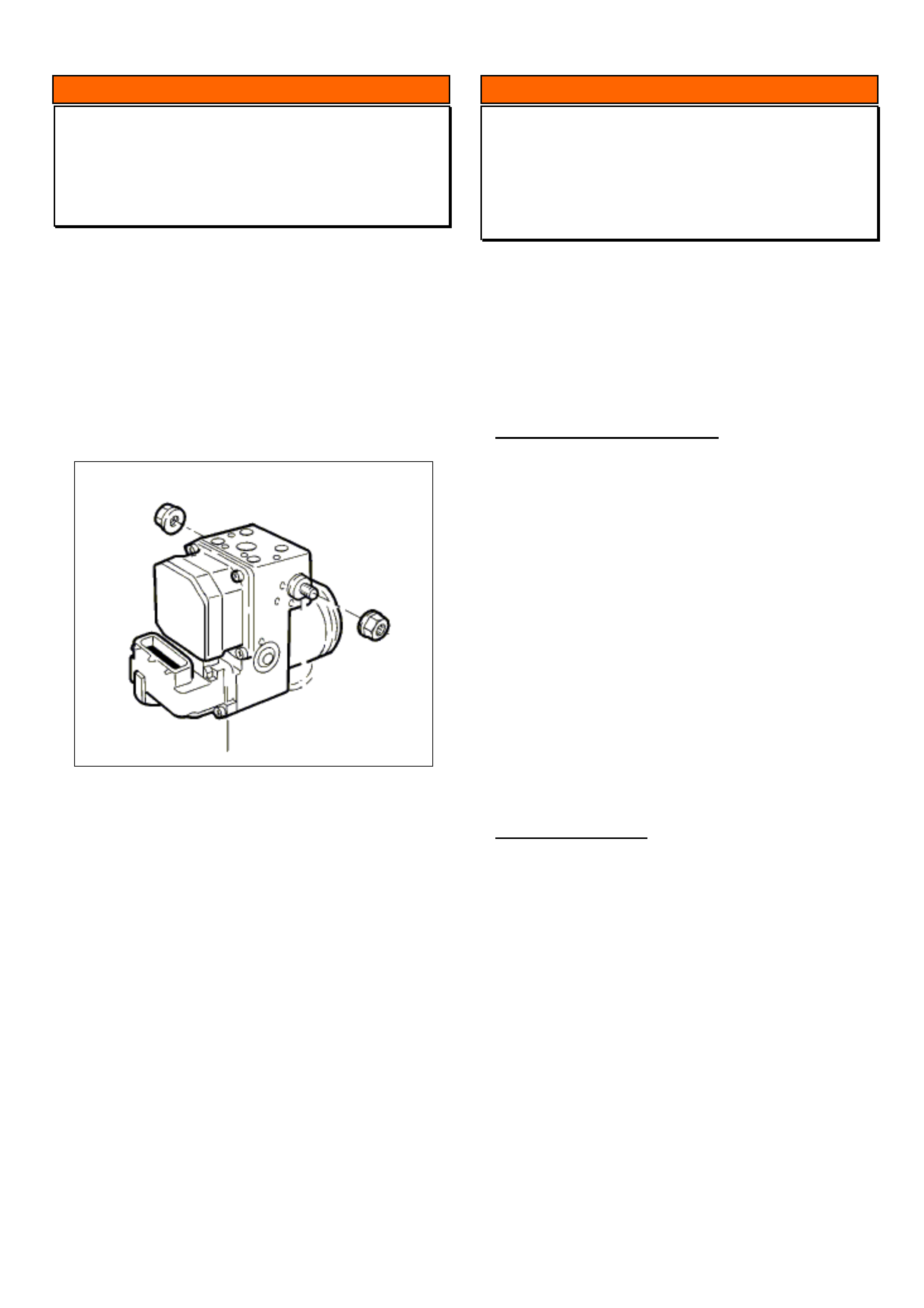
HOLDEN SERVICE TECHLINE______________________________________________________________SEPTEMBER, 2003
16
INFORMATION
ABS Replacement
V & W
(GROUP 5) TL567-0309
If ABS replacement is required under new vehicle
warranty, first seek approval from BOSCH via the
Prior Approval Process.
When BOSCH approval is given, the ABS Control
Module and Hydraulic Modulator assembly must be
replaced as a complete unit.
DO NOT REPLACE INDIVIDUAL COMPONENTS.
INFORMATION
Service Techline Numbering System
All
!
(GROUP OB) TL568-0309
The purpose of this item is to explain about a new
Techline numbering system which commenced in
Issue 2 / March 2002.
Every Techline now has its own unique number as
indicated in the heading box above.
How To Interpret The Number.
To help explain what the number means we will use
this Techline’s number, TL568 – 0309, as an
example.
TL568. This is a specific number which is assigned
to each new Techline. It is the next sequential
number from the Master List of techlines.
If there is a letter after the number, e.g. TL560A, this
signifies the first reissue. TL560B signifies the 2nd
reissue and so on. Techlines are reissued for various
reasons such as revisions, updates, repeats etc.
0309
03 = The year of publication (2003)
09 = The issue number.
RECOMMENDATION
The Techline number should be quoted whenever you
refer to a specific Techline in conversations with TAS,
CAS, Holden Aftersales personnel etc.

HOLDEN SERVICE TECHLINE________________________________________________________________OCTOBER, 2003
6
DIAGNOSIS HINT
Cruise Control “Drops Out” Due to
Incorrect Programming of CIM
ZC
(GROUP 12) TL581-0310
Some customers may report that the cruise control
intermittently drops out for no apparent reason. This
condition usually occurs when the vehicle is
attempting to maintain vehicle speed while on an
incline (going up a hill) or reduces vehicle speed
(going down a hill) with the cruise control set.
Investigations show that the cause for this condition is
incorrect programming of the Column Integration
Module (CIM).
When programming the configuration list within the
CIM there are three options, which can be selected
“Not Present”, “Present” and “Adapt. C.”.
Currently vehicles in Australia or New Zealand only
have standard cruise control not Adaptive cruise
control.
SERVICE RECTIFICATION
To rectify a vehicle with this condition the following
procedure needs to be followed.
Step 1. Ensure that you have all the following before
continuing with this procedure,
• The vehicle security code (on security card
when vehicle is delivered).
• All the keys for the vehicle.
(Failure to reprogram any keys will render
those keys inoperative until they are
reprogrammed.
• Tech 2 with the latest level of software and
CANdi adaptor.
Step 2. Using Tech 2, perform the following
selections, as well as any steps displayed on Tech 2.
F0: Diagnostics / Model Year / Vectra C / F0: Vehicle /
F2: Programming / Body / CIM / Reset CIM
Step 3. Once the CIM has been reset, Tech 2 will
return you to the CIM selection menu.
Now Select Program CIM and follow the Tech 2
screen prompts to the 6th screen, do not change any
parameters (except the one labelled “Cruise Control”),
continue to select the “Program “ & “Confirm” soft
keys until the parameter labelled “Cruise Control” is
displayed.
When this parameter is displayed use the arrow keys
on Tech 2 to highlight it and use the “Modify” soft key
to modify.
Select “Present” if the vehicle has cruise control or
“Not Present” if the vehicle does not have cruise
control.
Now select the “Program “ soft key and continue with
the Tech 2 screen prompts until all programming is
complete.
Note:
• When Tech 2 requests you to select the
Immobiliser programming routine, select “CIM
Installed”.
• When Tech 2 requests you to insert non
programmed transponders, use the original
vehicle keys.
Step 4. Check that the vehicle starts with all keys.
Step 5. Check for any current DTC’s and rectify as
required.
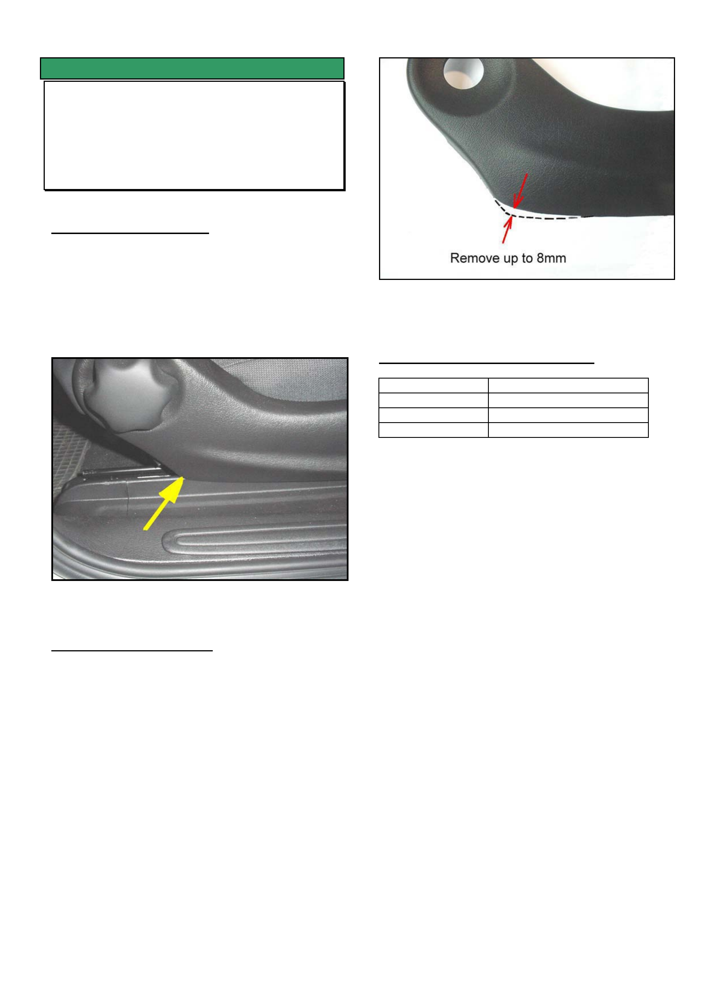
HOLDEN SERVICE TECHLINE________________________________________________________________OCTOBER, 2003
7
SERVICE FIX
Drivers Seat Squeaks in Fully Down
Position
VY built from April ‘03
(GROUP 1) TL577-0310
PROBLEM DESCRIPTION
Customer may complain of a squeak from the driver’s
seat while driving with the seat in the fully down
position.
This condition may be due to the seat cushion side
cover contacting the seat rail trim cover when the seat
is fully down. Refer Figure 1
Figure 1. Shows contact point
SERVICE RECTIFICATION
Summary: On complaint vehicles rework the side
cover as follows:.
1. Remove the seat side cover as per SIP
procedure.
2. Trim material from the cover as shown in Figure 2
Grinding on a bench grinder is the preferred
method to remove material. Remove any sharp
edges.
3. Reinstall side cover
4. Check that interference condition is eliminated.
Figure 2.
WARRANTY CLAIM INFORMATION
Description Trim seat side cover
Labour Op. No. C000499
Time 0.4 hr
Failure Code 62 Improper clearance
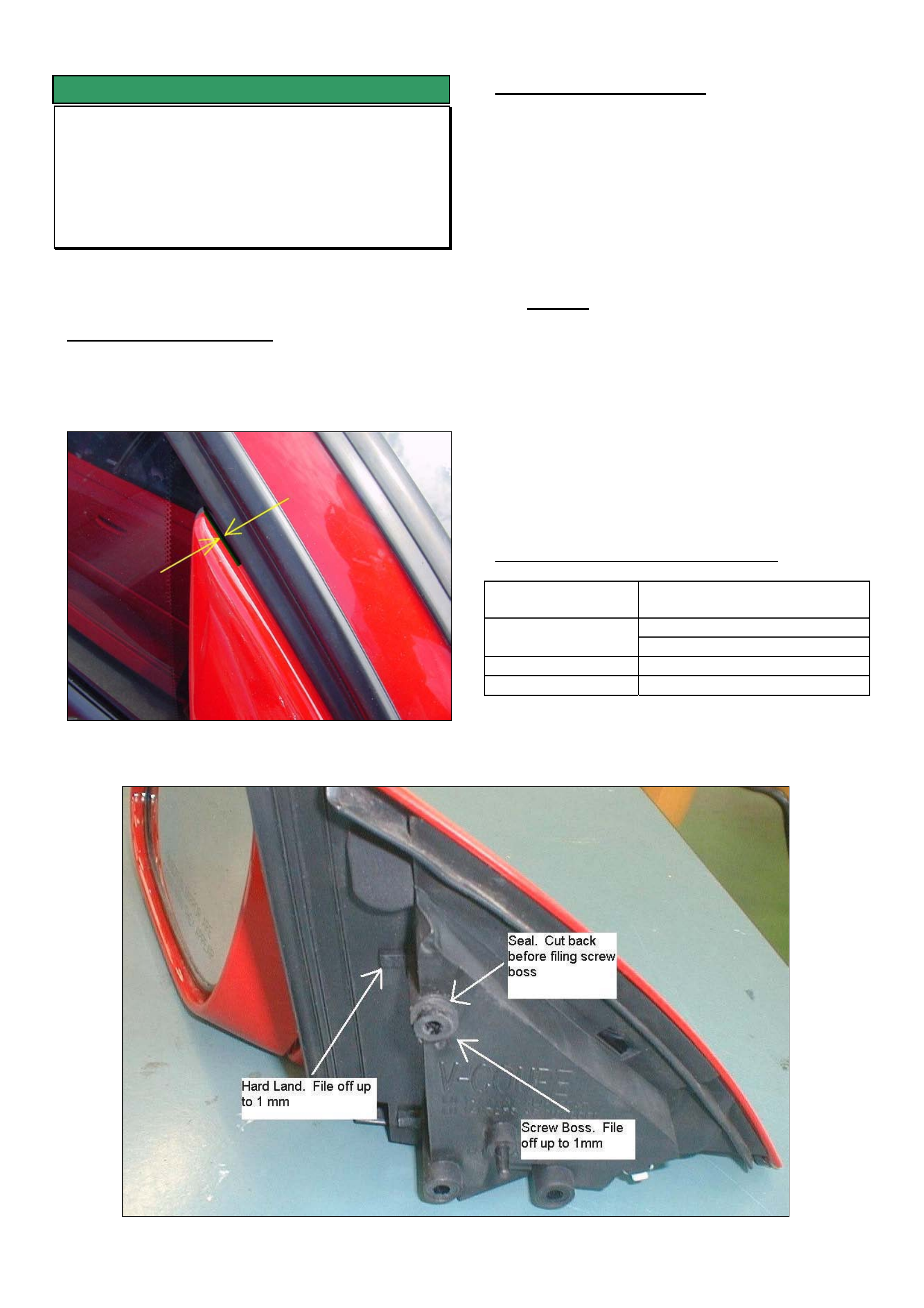
HOLDEN SERVICE TECHLINE________________________________________________________________OCTOBER, 2003
8
SERVICE FIX
Windnoise due to Gap in External
Rearview Mirror Mounting Base
V2
(GROUP 1) TL0557-0310
This techline should be read in conjunction with
Techline TL350A-0307 published in Issue 7, 2003.
PROBLEM DESCRIPTION
Front door windnoise complaints may be caused by
an excessive gap between the mirror base and
window seal as shown in Figure 1.
Figure 1. Shows gap in mirror mounting base
SERVICE RECTIFICATION
Summary: Rectify complaint vehicles by reworking
mirror as per following procedure.
1. Remove mirror from door as per procedure in
Passenger SIP CD.
2. Cut rubber seal back 1mm from the top of the
upper screw mounting boss (refer to Figure 2).
3. File up to 1mm from the upper screw mounting
boss and hard landing (refer to Figure 2).
Caution. Do not remove too much material off
the screw boss and hard landing otherwise the
window operation (and seal) may be adversely
affected.
4. Refit mirror to door.
5. Check that window operates correctly.
6. If wind noise is still evident, ensure that the
service rectification procedures in Techline
TL350A-0307 are performed.
WARRANTY CLAIM INFORMATION
Description Rework exterior mirror
mounting bosses
RHS - C000505
Labour Op. No.
LHS – C000508
Time 0.5 hr per side
Failure Code 45 wind noise
Figure 2. Shows areas to be reworked.
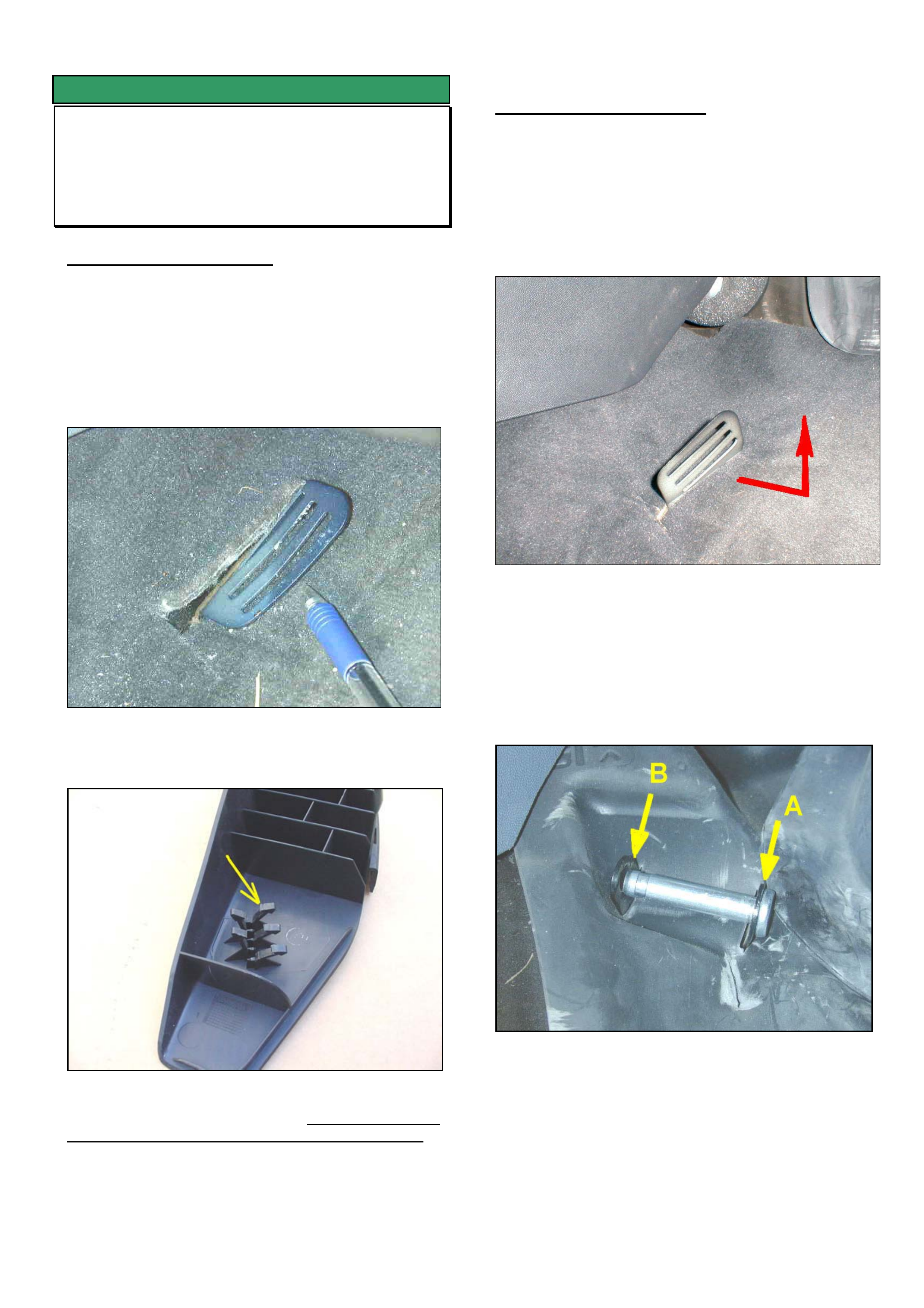
HOLDEN SERVICE TECHLINE________________________________________________________________OCTOBER, 2003
9
SERVICE FIX
Drivers Footrest Loose
ZC
(GROUP 1) TL0506-0310
PROBLEM DESCRIPTION
If the driver's footrest becomes loose, it may be
observed upon removal of the footrest, that the lower
retaining bracket is bent parallel to the floor as shown
in Figure 1. In addition, the plastic legs on the
underside of the footrest may be permanently
damaged as shown in Figure 2.
Figure 1. Shows lower retaining bracket bent parallel
to the floor.
Figure 2. Underside of footrest showing retaining
legs with permanent damage. Footrests with the
retaining legs spread as shown must not be reused.
SERVICE RECTIFICATION
Summary: On vehicles where the footrest has come
loose as described, install a new footrest as follows.
(1) Remove old footrest by removing retaining pin.
Do not reuse old footrest.
(2) Bend the lower metal retaining bracket so that it
is at right angles to the floor. Refer Fig 3.
Figure 3. Lower retaining bracket rebent to upright
position
(3) Insert pin into floor brackets as shown in Figure 4.
When the pin is fully inserted it must protrude
through bracket B. Bend brackets as required to
achieve this. Remove pin and go to next step.
Figure 4. Shows incorrect pin installation. Pin must
protrude through bracket B.
(4) Align new footrest with retaining pin bracket and
fully insert pin. Refer Figure 5. It is
recommended to pivot the footrest upwards and
check from underneath that the pin is correctly
installed.
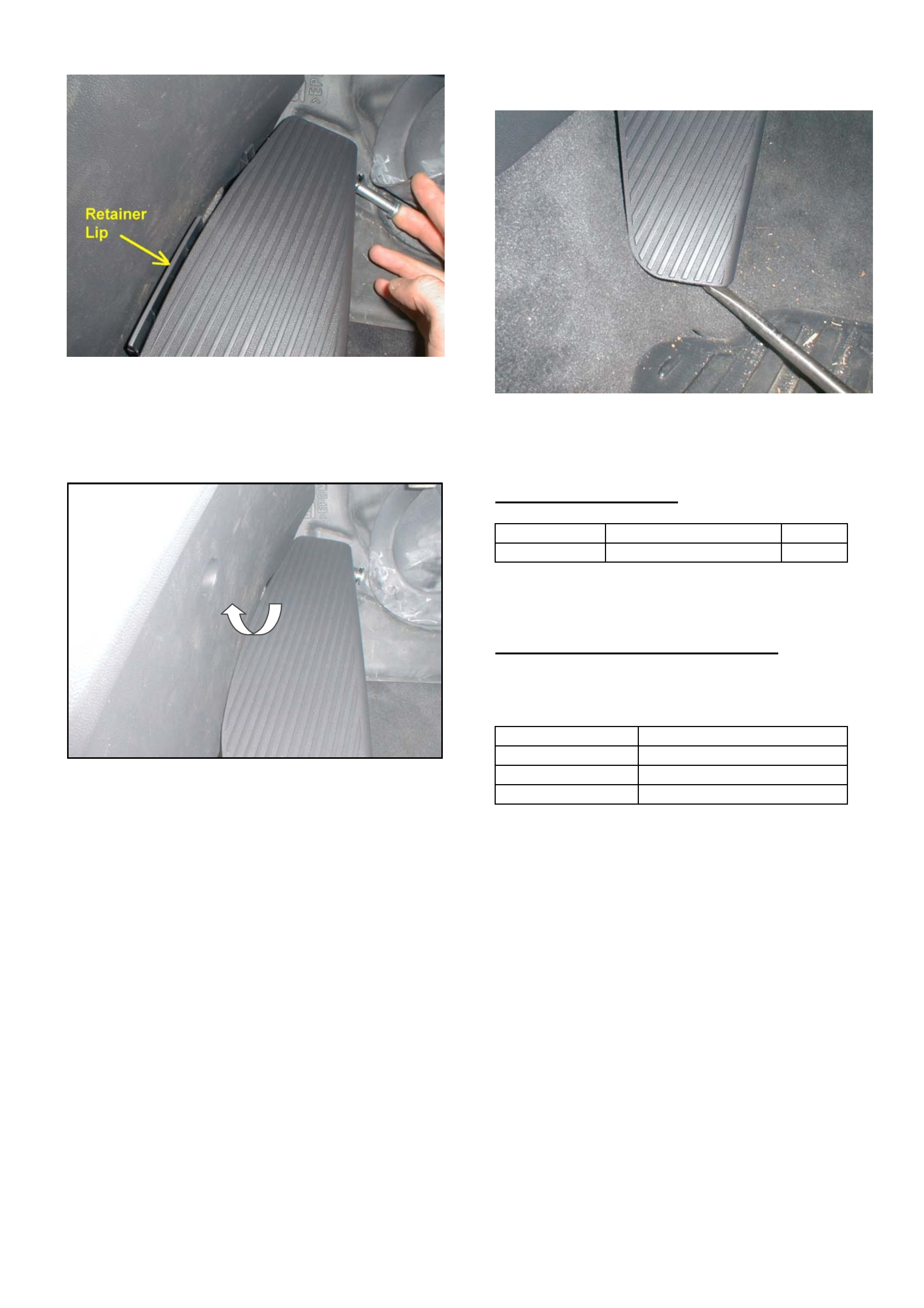
HOLDEN SERVICE TECHLINE________________________________________________________________OCTOBER, 2003
10
Figure 5.
(5) Tuck footrest lip under the centre console trim as
shown in Figures 5 & 6.
Figure 6
(6) Prior to locking the lower edge of the footrest to
the floor bracket, check that the footrest retaining
legs line up with the bracket. Bend the bracket as
required to achieve alignment.
(7) Press footrest down until a click is heard as the
barbed legs engage with the first slot in the floor
bracket.
(8) Push footrest fully down until a 2nd click is heard.
Check the footrest is firmly locked down by gently
levering with a screwdriver as shown in Figure 7.
Figure 7. Checking retention to lower bracket
PARTS INFORMATION
Part No.: Description: Qty:
24453499 footrest 1
WARRANTY CLAIM INFORMATION
Use following Labour Times information which will be
updated in the Warranty Information section of the
next PV SIP CD
Description Footrest - Replace
Labour Op. No. C001100
Time 0.3 hr
Failure Code 27 loose

HOLDEN SERVICE TECHLINE________________________________________________________________OCTOBER, 2003
11
INFORMATION
CDs Jammed in Blaupunkt Audio Head
Units -
VY, V2, WK
(GROUP 12) TL578-0310
Where an audio head unit defect involves CD’s that
do not eject from the unit, Retailer Technicians are
reminded they:
• MUST NOT open the unit to retrieve
the CD’s or forcefully remove them.
• MUST complete the form titled “CD’s Enclosed”
and fax it to Blaupunkt together with the
completed Audio Replacement Authorisation
Request form. Note, both these forms are to be
found in PV SIP CD in the section:
“SPECIAL WARRANTY COMPONENT
REPLACEMENT REQUIREMENTS”
Blaupunkt will exercise all care for the safe remova lof
jammed CDs and prompt return to the Retailer or
directly to the customer (as applicable).
WARNING
Retailers who do not comply with the above
requirement, requesting that the unit not be opened
prior to return, will be charged back by Holden for the
cost of the unit as this voids warranty.
DIAGNOSIS ASSISTANCE HELP LINE
If you require diagnosis assistance of any kind on
Blaupunkt audio units call Blaupunkt on toll free
number 1300 307 036
DIAGNOSIS HINT
DTC P0403 & P1405 set after
Reprogramming ECU
XC SRi (Z18XE engine) built between
W0L0XCF0834185543 (Feb 03) &
W0L0XCF0834255266 (Mar 03)
(GROUP 6C) TL0566-0310
PROBLEM DESCRIPTION
Currently, if a vehicle built within the range specified
has the ECU reprogrammed with the latest software
from TIS 43, 44 or 45, the following DTCs can
become logged:
• P0403 (EGR circuit malfunction)
• P1405 (Feedback Sensor EGR)
Root Cause.
Commencing Feb. 2003 the above models received a
revised catalytic converter and the EGR valve was
deleted. These changes required a new ECU
calibration to be released.
The VIN number breakpoint (for introduction of these
changes) used in TIS2000, versions 43, 44, & 45 is
incorrect as it prompts cars with the new hardware
changes to be re-flashed using the old calibration
software “09 115 113.2307". It should prompt for new
calibration software “55 351 753.2305" to be installed.
SERVICE RECTIFICATION
This issue will be rectified with TIS 2000 version 46
which will be at Retailers in early Nov. 2003.
Until TIS 2000 version 46 is available, be aware that
any XC SRi vehicle between W0L0XCF0834185543
and W0L0XCF0834255266 will set DTCs P0403 and
P1405 after reprogramming the ECU.
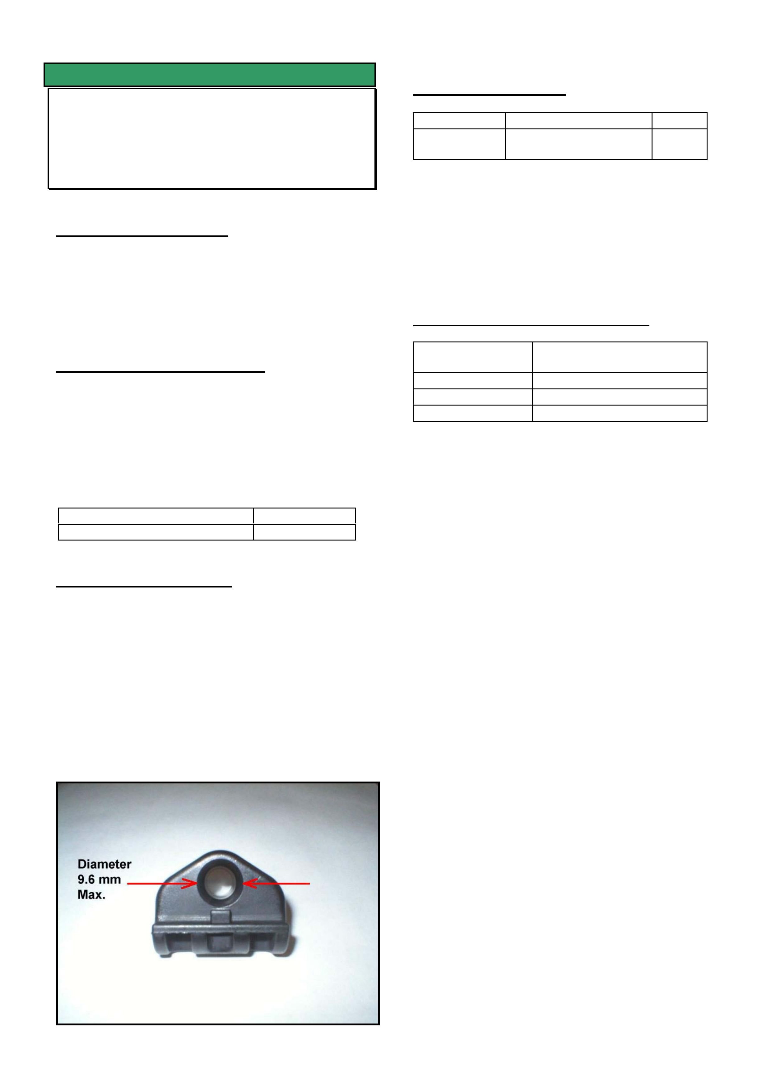
HOLDEN SERVICE TECHLINE________________________________________________________________OCTOBER, 2003
12
SERVICE FIX
Soft Tonneau Cover Rattle
VU, VY Ute
(GROUP 1) TL582-0310
.
PROBLEM DESCRIPTION
Some customers may complain of a rattle noise from
the soft tonneau cover when driving in high cross
wind conditions.
Investigations show the rattle is causd by the two rear
cross bars rattling in their plastic support brackets.
PRODUCTION RECTIFICATION
The plastic support brackets have been modified by
decreasing the diameter of the socket to 9.4 - 9.6mm
as shown in Figure 1. This diameter was previously
10.5 – 10.7mm.
Revised brackets with reduced clearance have been
fitted to vehicles in production from:
ISOVIN: Build Date:
6G1YK43A04L192447 29/10/03
SERVICE RECTIFICATION
On complaint vehicles proceed as follows.
1. If vehicle is fitted with cross bar brackets with a
hole diameter greater than 9.6mm install new
brackets from HSPO.
2. Ensure that the tonneau cover is tensioned
correctly as per page 3-24 of Owner's Manual (refer
'Note' under Fitting tonneau cover to front bar).
_______________________
PARTS INFORMATION
Part No.: Description: Qty:
92089554 Bracket - tonneau
cover bar
4
NOTE: The part number of the revised bracket (with
the smaller hole) has not changed.
Attention Parts Managers:
Any of the old brackets with hole diameter in the
range of 10.5 – 10.7mm should be returned to HSPO
for credit via the CRRM system.
WARRANTY CLAIM INFORMATION
Description Replace tonneau bar
brackets
Labour Op. No. C000502
Time 0.2hr
Failure Code 28 rattle
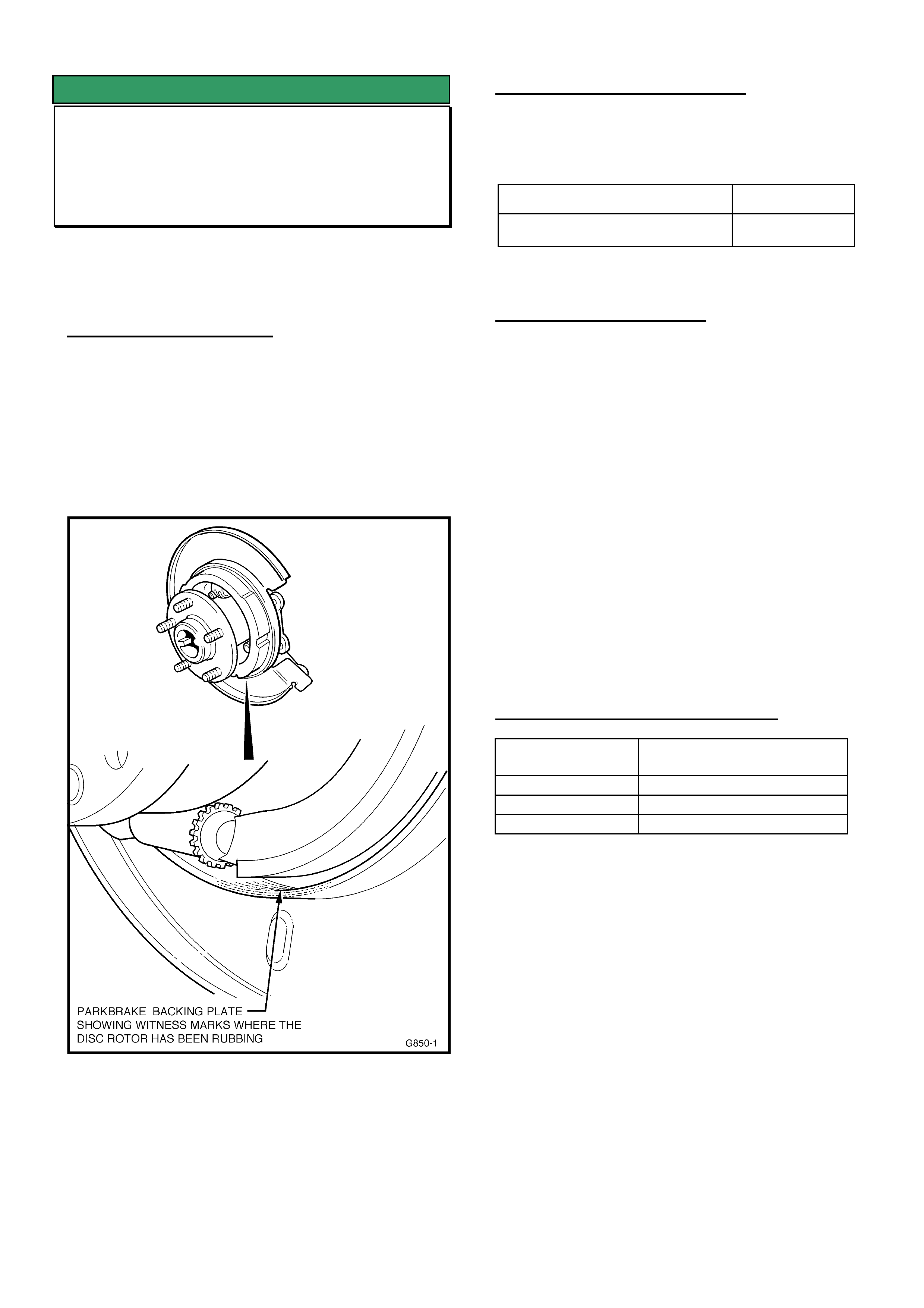
HOLDEN SERVICE TECHLINE________________________________________________________________OCTOBER, 2003
13
SERVICE FIX
Rear Disc Brake Scraping Noise
VY Regular Cab & Crewman
(GROUP 4 & 5) “REVISED” TL555A-0310
This Techline supercedes the previous one
TL555-0309 in Issue 9, Oct, 2004. It is revised by
adding Crewman to the affected models.
PROBLEM DESCRIPTION
Some vehicles may experience a scraping noise from
the rear brakes when loaded, cornering or travelling
over bumps at low speed.
Investigations show this noise is caused by the disc
brake rotor scraping on the backing plate sealing
flange, because of insufficient clearance. Figure 1
below shows the exact contact area.
Figure 1 – Showing typical rear backing plate
“scrape” marks on the sealing flange - with disc brake
rotor removed
PRODUCTION RECTIFICATION
Revised rear axle assemblies with increased
clearance between rotor and backing plate have been
fitted to vehicles from:
ISOVIN No.: Build Date:
6G1YK03A33L167677 02/09/03
SERVICE RECTIFICATION
Summary: Replace Axle assembly.
• For any vehicle with the above condition:
Replace the rear axle assembly with a new
changeover unit from DANA. (Refer to the SIP CD
VY “Special Warranty Component Replacement
Requirements” section).
NOTE: When requesting an exchange axle unit –
ensure the description “Disc Brake Scraping” is
shown on the request.
Use the standard procedure as outlined in SIP for
replacing the rear axle assembly.
IMPORTANT:
DO NOT attempt to rectify the above condition by
machining the brake rotor in the area that contacts the
backing plate.
WARRANTY CLAIM INFORMATION
Description Rear Axle Asm. –
Replace for Disc Scrape
Labour Op. No. F000191
Time 2.1 hr
Failure Code 31

HOLDEN SERVICE TECHLINE________________________________________________________________OCTOBER, 2003
14
INFORMATION
Loss of ECC Temperature Memory
VX, WH and V2 built after Aug. 2001
(GROUP 2) TL507-0310
PROBLEM DESCRIPTION
Customers may complain that the temperature setting
on the ECC controller has changed from the last time
they used it.
The above condition occurs as a result of revised
software that was introduced into ECC controllers
from Aug 2001.
SERVICE RECTIFICATION
On vehicles with the above condition, fit a new ECC
controller from HSPO (part numbers below) which
have been programmed with pre-Aug 2001 software
to eliminate the above condition.
PARTS INFORMATION
Part No.: Description: Qty:
92111236 ECC control module
– dual zone
1
92111235 ECC control module
– single zone
1
WARRANTY CLAIM INFORMATION
Use normal Labour Times information in Warranty
Information section of current Passenger SIP CD
SERVICE FIX
Revised Trailer Wiring Harness
ZC
(GROUP 12) TL573-0310
PROBLEM DESCRIPTION
The intensity of the trailer parking lamps varies under
some conditions.
The above condition is restricted to those vehicles
fitted with the original HSPO harness p/n 92145316.
SERVICE RECTIFICATION
A revised trailer wiring harness that rectifies the
above condition is now available from HSPO.
If a customer complains of the above condition it is
recommended that the existing harness be replaced
with revised harness p/n 92147274.
PARTS INFORMATION
Part No.: Description: Qty:
92147274 Trailer harness with
conrol unit
1
Attention Parts Managers:
Trailer wiring harness p/n 92145316 should be
quarantined and then returned to HSPO for credit via
the CRRM system.
WARRANTY CLAIM INFORMATION
Description Trailer Wiring Harness-
Replace
Labour Op. No. R603600
Time 0.8 hr
Failure Code 48 Electrical Harness
Problem

HOLDEN SERVICE TECHLINE______________________________________________________________NOVEMBER, 2003
7
SERVICE FIX
Fuel Gauge Intermittently Reads Incorrect
Value
V2 II & V2III, WK, VYI & II - excluding VY
Series 1 Ute
(GROUP 12) TL605-0311
PROBLEM DESCRIPTION
Customers may advise that the fuel gauge reads
inaccurately in the region below a quarter of a tank.
The root cause of this condition has been isolated to
the fuel gauge calibration.
PRODUCTION RECTIFICATION
A revised fuel gauge calibration was introduced into
VYII, V2 III and WK production except V6
Supercharged models from:
ISOVIN: Build Date:
6G1YK82A74L199047 11/11/03
SERVICE RECTIFICATION
The revised calibration for all models, except V6
supercharged and VY Series 1 Regular Cab, will be
available on TIS 2000 CD 47, Tech 2 software version
12.700, which is scheduled for despatch on the
17/12/03. An updated techline advising of a revised
calibration for those models not included will be
published in Feb. 2004.
If presented with a vehicle where the customer
advises of this condition perform the following steps:
1. Check the F-4 co-ordinate of the Vehicle Service
History Label located on the inner side of the
lower instrument panel cover. If this co-ordinate
location is marked, the instrument cluster re-
calibration has already been performed. If no
label or co-ordinate markings are present
continue to step 2.
2. To reprogram the fuel gauge calibration refer to
SIP Electrical System / Section 12 C Instruments /
3.15 Programming.
3. After re-programming the fuel gauge calibration a
service history label is required to be fitted to the
inner side of the lower instrument panel cover and
co-ordinate F-4 marked with an X.
WARRANTY CLAIM INFORMATION
Description Re-program Fuel Gauge
Calibration
Labour Op. No. N000453
Time 0.3 hrs
Failure Code 57 Registers incorrectl y
Failure Code NOW N0057 Registers incorrectly
SERVICE FIX
Cabin Boom In Speed Range from
80 – 100 Km/h
VY Reg. Cab, VY Crew Cab, with V6 A/T
(GROUP 1 & 4) TL0595-0311
PROBLEM DESCRIPTION
Some vehicles may experience excessive cabin boom
in the speed range of 80 – 100 km/hr with the TCC
engaged.
PRODUCTION RECTIFICATION
A revised TCC engagement speed (higher) has been
introduced via PCM calibration into vehicles from:
ISOVIN: Build Date:
6G1YK32A54L152926 09/09/03
SERVICE RECTIFICATION
To rectify complaint vehicles, reprogram the PCM
using the latest “High Speed TCC” software as follows
from TIS 46 (or later).
NEW
92209181 - High Speed TCC application.
REPLACES
92165801 - Low Speed TCC application
92163781 - “ “ “
92169214 - “ “ “
IMPORTANT. Vehicles that do not have
the complaint condition must not be
reprogrammed with the High Speed TCC
software.
WARRANTY CLAIM INFORMATION
Description Reflash PCM
Labour Op. No. J000740
Time 0.4 hr
Failure Code 36 Vibrates
Failure Code NOW J0036 Vibrates
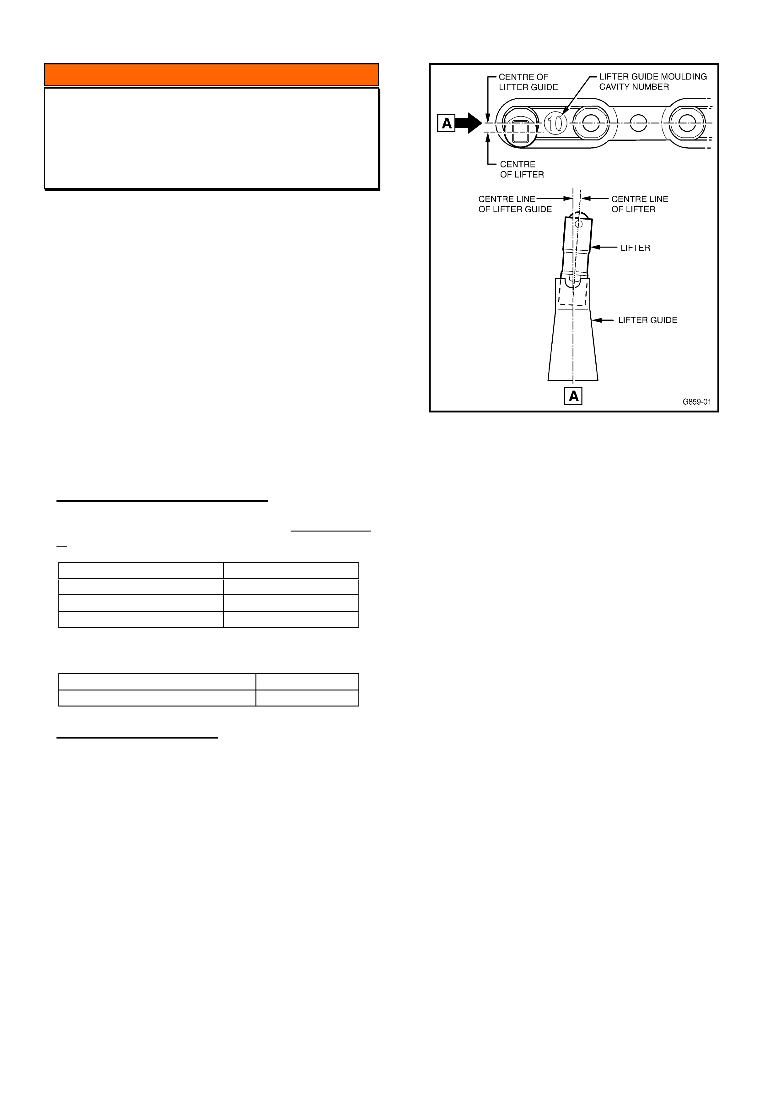
HOLDEN SERVICE TECHLINE______________________________________________________________NOVEMBER, 2003
8
INFORMATION
Hydraulic Lifter Noise
Gen III V8 Engine
(GROUP 6A) TL0604-0311
This bulletin has been released to dispel “concerns” of
hydraulic lifters or lifter guides causing “lifter noise”
and needing replacement during an engine rebuild.
___________________________________________
A small number of lifter guides were manufactured
with distortion. These parts were identified by the
moulding cavity number “10” on the underside of the
guide. Not all parts identified with the “10” are
affected.
The parts with distortion were used in only a small
range of engines and the tooling was revised in
production to remove the possibility of distortion.
The lifter guides with distortion caused loud lifter
noise early in vehicle life, thus were replaced
immediately when the sound was identified.
PRODUCTION RECTIFICATION
The range of engines that contained a small number
of affected lifter guides was:
From Engine No.: Engine Build Date:
VF010010001 01/01/01
To Engine No.: Engine Build Date:
VF011520001 01/05/01
Improved cavity “10” lifter guides were used from:
Engine No.: Build Date:
VF011520002 01/06/01
SERVICE PRECAUTION
To ensure no distorted lifter guides are re-used during
an engine repair – inspect the underside of the lifter
guides for the presence of the moulding cavity
number - as shown in Figure 1 - if a guide with the
number “10” are fitted – place lifters in the guide and
inspect for noticeable mislocation of any lifter. All
lifters should be vertical – on the same centre line as
the lifter guide. If there is any noticeable mislocation
as shown – replace the lifter guide with a new part
from HSPO.
Figure 1 - showing the obvious distortion that a
‘suspect’ lifter guide will cause.
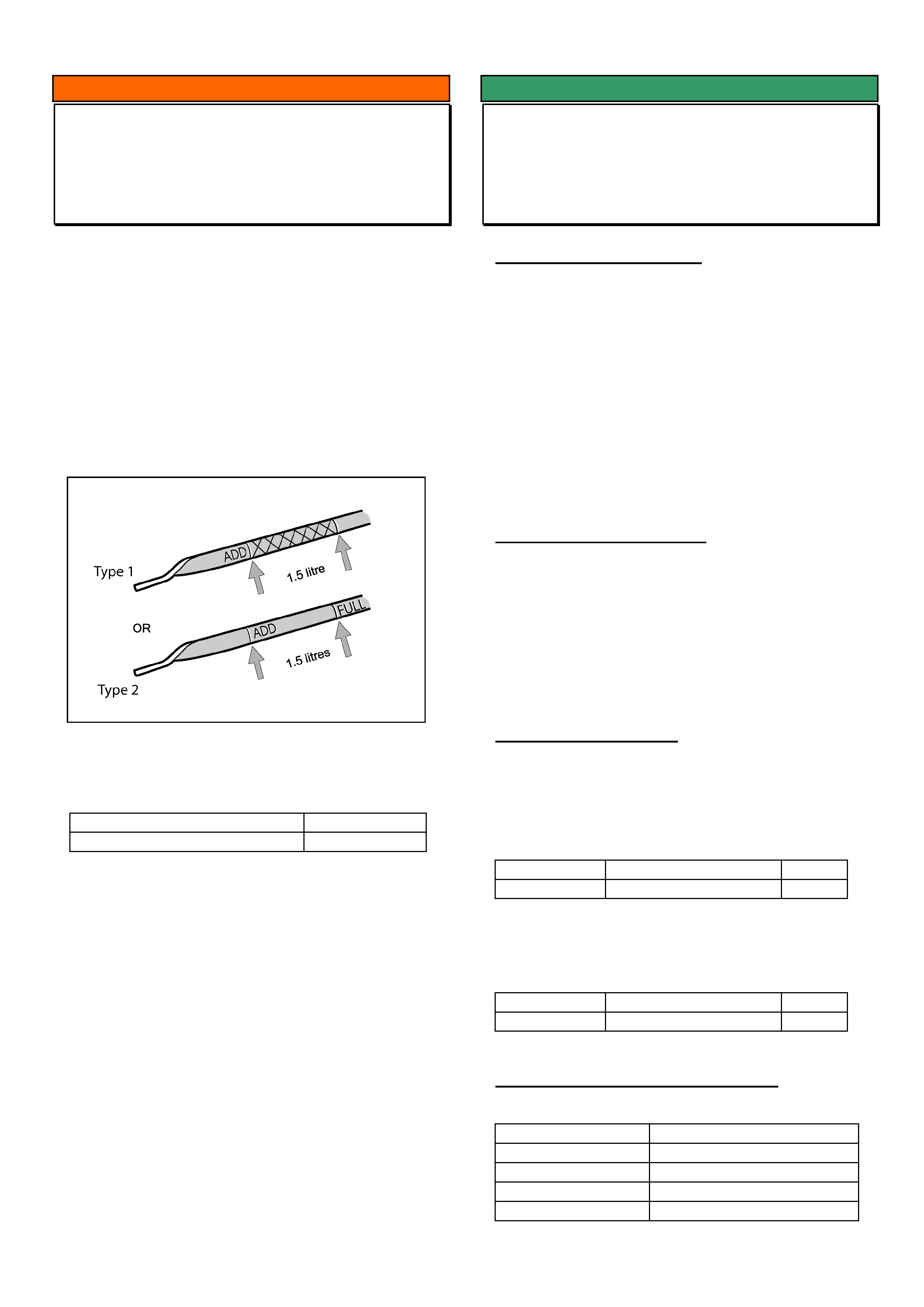
HOLDEN SERVICE TECHLINE______________________________________________________________NOVEMBER, 2003
9
INFORMATION
Engine Oil Dipstick Revision
VY Series II with V6
(GROUP 6A) TL0606-0311
The oil dipstick has been revised by the inclusion of a
cross-hatched section to show the normal ‘operating
range’ for the engine oil level.
The revised dipstick is shown as “Type 1” in Figure 1
below.
The previous dipstick is shown as “Type 2”.
Figure 1 is a copy from the latest Owner Handbook
published for VY Series II since September, 2003.
Figure 1.
Revised oil level dipsticks have been fitted to vehicles
from:
ISOVIN: Built Date:
6G1YK52AX4L206913 TBA
For reference: the first engine using this new dipstick
is: Engine No. VA395155.
SERVICE FIX
TCC Engagement Shudder
JS with C22SEL Engine
(GROUP 7B) TL0591-0311
PROBLEM DESCRIPTION
Some vehicles may display an unacceptable
“shudder” feeling during Torgue Converter Clutch
(TCC) engagement at approx. 80 km/h.
This “shudder” may be pronounced when decelerating
and re-applying throttle around 75 – 85km/h - when
TCC re-applies.
The cause of this shudder is the calibration of the
Transmission Control Module (TCM).
A new TCM with revised calibration to overcome this
condition has been released for service usage.
SERVICE RECTIFICATION
Summary: Fit a new TCM.
Vehicles that display this shudder may be corrected
by fitting a new TCM.
NOTE: There are two different types of TCM – which
must be selected from the “Parts Information” section
below. Inspect the vehicle to define the type of TCM
installed to the vehicle, before ordering the part from
HSPO.
PARTS INFORMATION
NOTE: There are two types of TCM’s used in this
engine/transmission configuration, as follows:
For vehicles up to ISOVIN W0L0JBF19XL446840:
TCM Code “DA”, production part 92059174, (large
type TCM) is used – replaced by New Service Part:
Part No.: Description: Qty:
92147244 Trans. Cont. Module 1
For vehicles from ISOVIN W0L0JBF19XL446841:
TCM Code “DB”, production part 92077883 (small
type TCM) is used – replaced by New Service Part:
Part No.: Description: Qty:
92147245 Trans. Cont. Module 1
WARRANTY CLAIM INFORMATION
Use existing Labour Operation for TCM replacement:
Description Replace TCM
Labour Op. No. K509600
Time 0.4 hr
Failure Code 41 Chatters
Failure Code NOW K0041
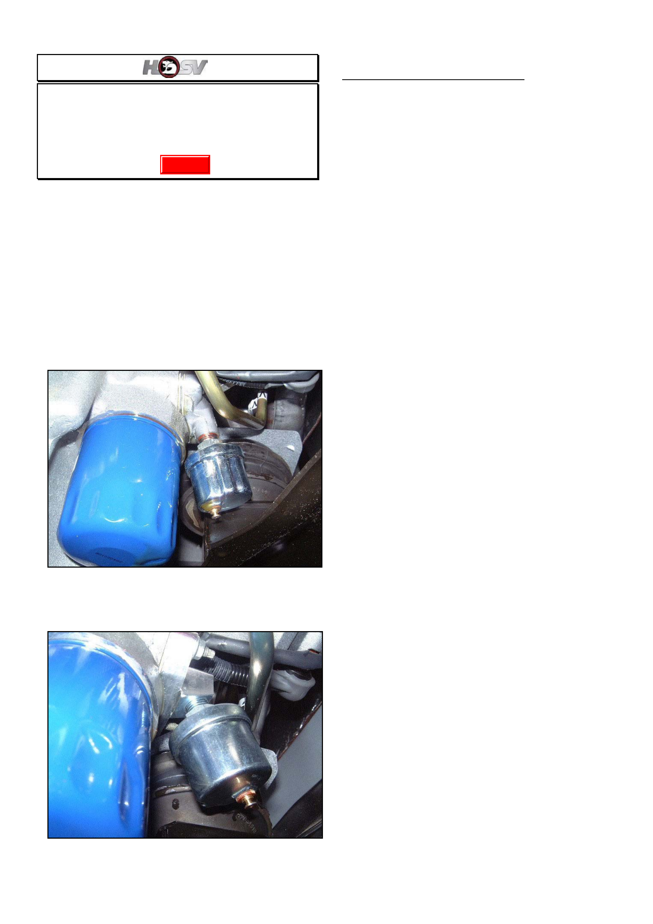
HOLDEN SERVICE TECHLINE______________________________________________________________NOVEMBER, 2003
10
Oil Sender Adaptor Fouls On HSPO Oil
Filters
HSV vehicles with optional gauges
(GROUP 6A) TL0598-0311
The following information has been supplied by HSV
for distribution to all Holden retailers
Oil sender adaptor part No 06G - 020601 as fitted to
HSV vehicles with optional gauges does not provide
enough clearance for some types of oil filters fitted in
service. Refer Figure 1.
New part No 06G – 030601 provides more clearance
(refer Figure 2.) and is available from your HSV
State Distributor.
Figure 1. Old Adaptor
Figure 2. New Adaptor
LIST OF HSV DISTRIBUTORS
SUTTONS PARTS
22 CARTER ST, LIDCOMBE, N.S.W., 2141
PH: 02 9648 3688
FAX: 02 96471483
Email: [email protected]
HSV Specialist. Miss Kerri Wilkens
MD/General Manager Mr Darrall Elson
PRESTON MOTORS
1551 SYDNEY RD, CAMPBELLFIELD, VICTORIA
3061
PH: 03 9359 3999
FAX: 03 9357 3350
Email: [email protected]
HSV Specialist. Mr. Shaun Lacey
MD/General Manager Robin Mc Clean
ZUPPS PARTS
1032 BEAUDESERT RD, COOPERS PLAINS, QLD
4108
PH: 07 3259 5051
FAX: 07 3875 1773
Email: [email protected]
HSV Specialist.Mr Richard Morris
MD/General Manager Mr Robert Lemon
AMCAP BBK
171 WELSHPOOL RD, WELSHPOOL, W.A. 6106
PH: 08 9351 6666
FAX: 08 9351 6636
Email: [email protected]
HSV Specialist. Mr Noel Learson
MD/General Manager Mr Peter Hewett
METRO HOLDEN
THEBARTON, 1 PORT RD, S.A. 5031
PH: 08 8354 0555
FAX: 08 8352 6678
Email: [email protected]
HSV Specialist. Mr Roger Kramer
MD/General Manager Mr Trevor Olsen
Update
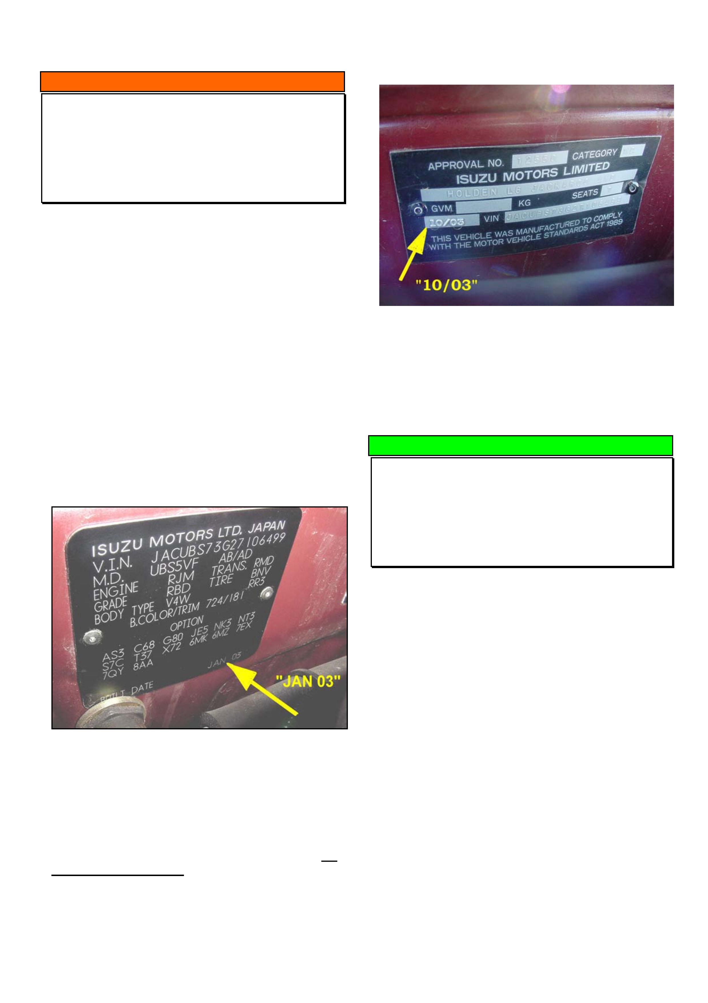
HOLDEN SERVICE TECHLINE______________________________________________________________NOVEMBER, 2003
11
INFORMATION
Built Date Explained
All Imported Vehicles – XC, TS, TT, JS,
ZC, UES, UBS, RA, YG
(GROUP OB) TL0606-0311
Holden Breakpoint Information in Service Techlines,
SMA handout material, Partfinder, etc. usually refers
to a BUILT DATE.
The BUILT DATE is the date the vehicle was
assembled in the factory.
Whenever quoting vehicle details in PIRs, talking to
TAS, etc., always quote the vehicle BUILT DATE.
The BUILT DATE is located in various locations on
imported vehicles.
On TS it is shown on a small label on the radiator
panel. On ZC it is shown on a small label on the strut
tower.
On UBS Jackaroo the BUILT DATE is shown on the
Body/Option plate on the dash panel as shown in
Figure 1.
Figure 1. Body/Option plate - Jackaroo
IMPORTANT. The BUILT DATE described above
must not be confused with the date stamped on the
Safety Compliance Plate rivetted to the dash panel.
Refer Figure 2.
The date shown on the Safety Compliance Plate, for
imported vehicles only, is the date when the plate
was attached to the vehicle at the Port Of Entry (POE)
into Australia. This date can be from 2 to several
months after the vehicle BUILT DATE because of the
time taken for shipping the vehicle to Australia plus
storage at POE.
Figure 2. Safety & Compliance plate - Jackaroo
SERVICE HINT
Transferring Information from Old to New
Modules
All
(GROUP 12) TL0589-0311
When installing a new module the following
information is generally required for inputting into the
new module.
• Vehicle options
• Vehicle configuration
• Code Index
Prior to removing any module, it is recommended to:
1. Connect Tech 2.
2. Record on paper the Vehicle options, Vehicle
configuration, and Code Index.
3. Confirm all the values recorded in step 2 using
TIS 2000 or SIP.
4. Once these values are confirmed they can then
be entered into the new module when called for
by Tech 2 during the installation process.
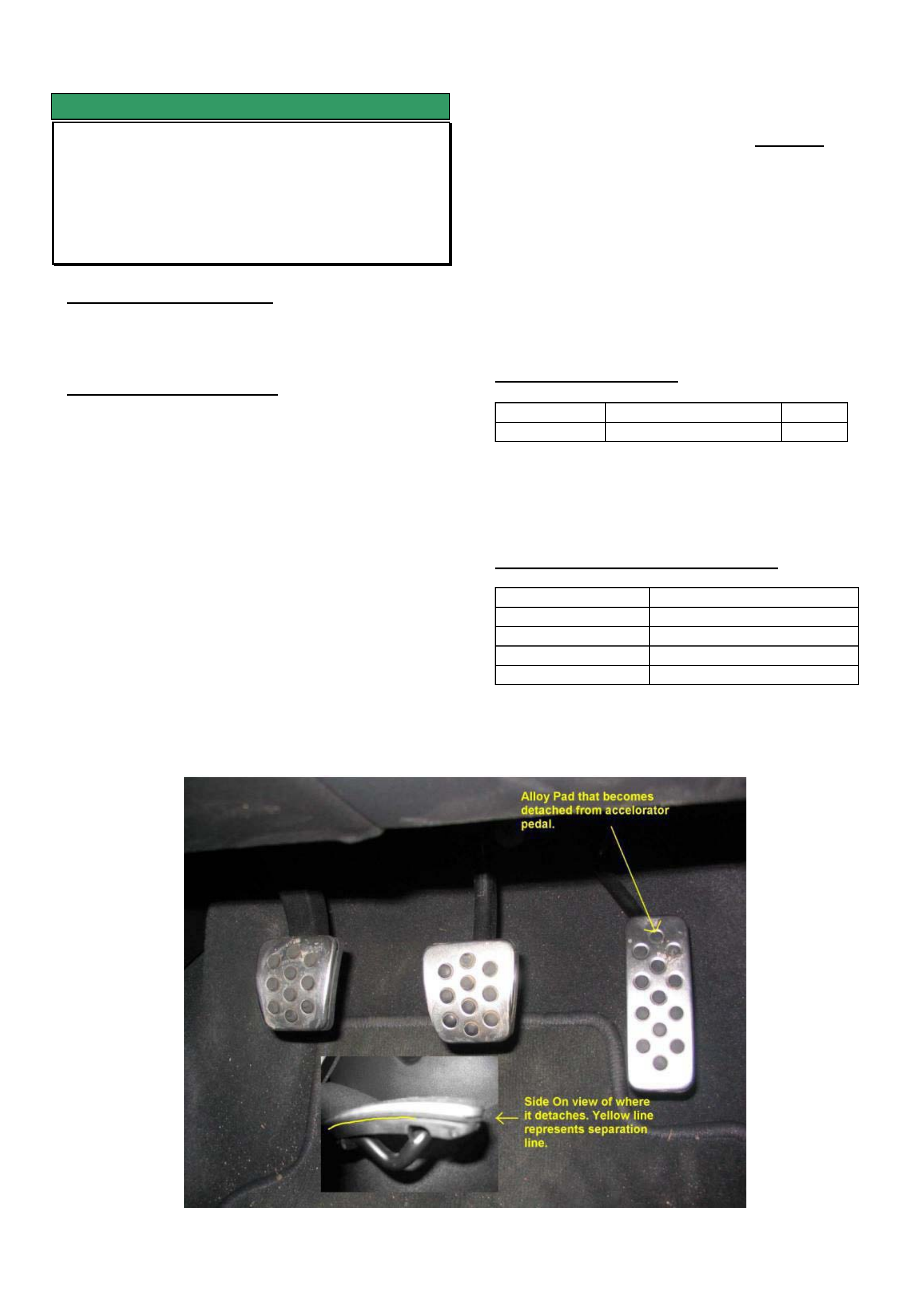
HOLDEN SERVICE TECHLINE______________________________________________________________NOVEMBER, 2003
12
SERVICE FIX
Alloy Pad Detaches from Accelerator
Pedal
TS Models with Alloy Pedals
(GROUP 1) TL0594-0311
PROBLEM DESCRIPTION
On some vehicles the alloy pad may detach from the
accelerator pedal. Refer Figure 1.
SERVICE RECTIFICATION
Summary: On complaint vehicles, reglue alloy pad to
accelerator pedal as follows.
NOTE: This fix is only applicable to the accelerator
pedal.
(1) If required, carefully remove alloy pad completely
from the accelerator pedal.
(2) Thoroughly clean the matching contact surfaces
of the alloy pad and the accelerator pedal with a
solvent such as X55 or Prepsol.
(3) Allow solvent to dry completely before next step.
(4) Apply Loctite 770 primer or equivalent to
completely cover the contact surfaces on both
alloy pad and accelerator pedal.
(5) Allow primer to dry completely (2 - 5 minutes).
(6) Apply Loctite 480 or equivalent, sparingly along
the ridges of the accelerator pedal. Loctite
application must be completed within 1 minute to
avoid curing prior to assembly.
(7) Place alloy pad on accelerator pedal and apply
light even pressure for 1 - 2 minutes until glue
initially sets.
(8) It is recommended to allow a minimum of 1 hour
before using the accelerator pedal.
PARTS INFORMATION
Part No.: Description: Qty:
55351855 Pad -alloy 1
Solvents and adhesives mentioned above can be
obtained from commercial suppliers. They are not
stocked by HSPO.
WARRANTY CLAIM INFORMATION
Description Alloy pad - Replace
Labour Op. No. C000511
Time 0.3 hr
Failure Code 71 Pulled loose
Failure Code NOW C0071
FIGURE 1
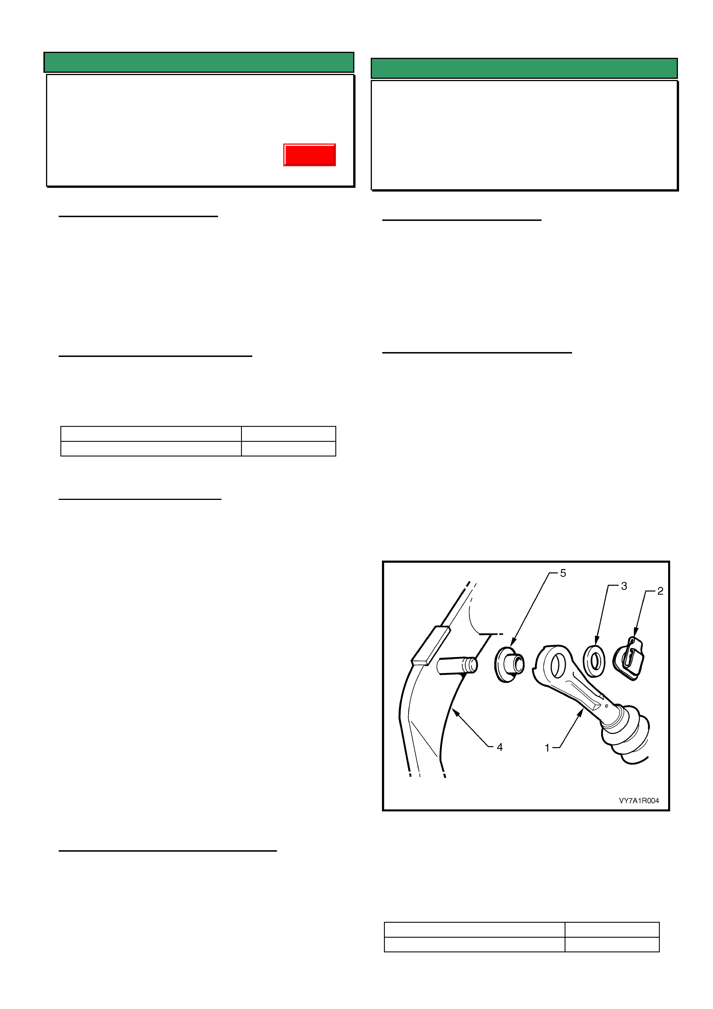
HOLDEN SERVICE TECHLINE______________________________________________________________NOVEMBER, 2003
13
SERVICE FIX
Blaupunkt Radio Losing Time or CD Will
Not Eject
VY / V2 II / WK
(GROUP 12) TL580-0311
PROBLEM DESCRIPTION
Customers may complain of the clock in their
Blaupunkt radio losing time or that the CD will not
eject.
After investigation into the root cause, Blaupunkt has
made a software revision to rectify this condition.
PRODUCTION RECTIFICATION
Blaupunkt has implemented a software revision for all
radios introduced into production as of the following
break point.
ISOVIN: Build Date:
6G1YX54AX4L170039 8/09/03
SERVICE RECTIFICATION
If a customer presents a vehicle with the above
condition, request a replacement radio using the
standard change over request procedure which is
found in SIP “ SPECIAL WARRANTY COMPONENT
REPLACEMENT REQUIREMENTS” section .
IMPORTANT: The Main Software Version number
must also be included on the request form.
Below is an example of the Identification Data screen
displayed on Tech 2 where this information can be
found.
Identifier 404
Part number 92118704
Production Date 60103
Main Software Version ????
Panel Software Version 1A22
Serial Number 804697
VIN Digit 1-10 6G1YK54A74
VIN Digit 11-17 L169008
WARRANTY CLAIM INFORMATION
Use Labour Times information in Warranty
Information section of current PV SIP CD
SERVICE FIX
Recommended Lubricant For Clutch
Pedal Squeak
VT, VU, VX, VY Series 1 – Manual Trans.
(GROUP 7A) TL0588-0311
PROBLEM DESCRIPTION
It has come to Holdens attention that many vehicles
are experiencing repeat repairs for clutch pedal
squeak.
It is believed that these repeat repairs are due to
incorrect lubricants being used and in particular,
aerosol spray lubricants which are considered not
suitable for this job.
SERVICE RECOMMENDATION
To avoid repeat repairs on complaint vehicles,
lubricate the clutch pedal to master cylinder
connection as follows.
1. Refer procedure in PV SIP to perform the
following.
2. Disconnect the clutch master cylinder push rod
(1) by removing the spring clip (2) and washer (3)
from the pin on the clutch pedal (4).
3. Use a brush to apply Molybond GA10 grease, or
equivalent, to the pin and both sides of the
washer. Do not over apply grease to avoid it
dripping onto the carpet.
4. Reassemble all components.
NOTE. The above procedure does not apply to VY
series II vehicles which have a new “quick connect”
(plastic) design for connecting the master cylinder to
the clutch pedal.
VY Series II was introduced from:
ISOVIN: Build Date:
6G1YK52A94L156716 06/08/03
Update
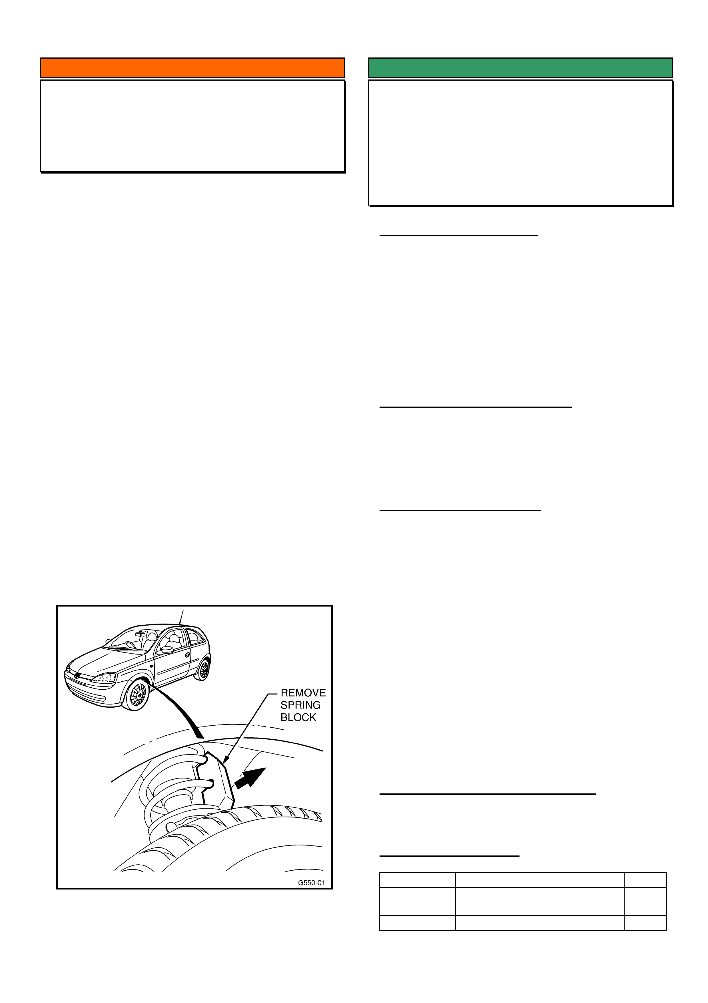
HOLDEN SERVICE TECHLINE______________________________________________________________NOVEMBER, 2003
19
INFORMATION
Front Spring Chock Removal
Various Models
(GROUP 3) TL0590-0311
Front spring chocks are currently fitted to the following
models to reduce instances of damage to front facias
when loading and unloading vehicles from vehicle
transporters. A label advising of spring chocks is
attached to the windscreen of these vehicles.
• VY ‘S' Pack Sedan
• VY 'SS' Sedan
• VY 'SS' Crewman
• VY 'SS' Chassis Cab
• VY 'SS' Ute
• VY 'SS' Wagon
• VY Calais
• V2 Monaro
• HSV vehicles
• XC Sri Barina
Holden is still receiving reports of vehicles being
delivered to customers with chocks not removed!
The spring chocks MUST be removed before
delivery to the customer.
To remove, lift vehicle on hoist, so the front springs
are unloaded, and remove chock from each front
spring. Figure 1 shows spring chocks in Barina Sri.
Other vehicles use timber chocks.
Figure 1. Shows spring chock arrangement in an XC
SRi.
SERVICE FIX
Clutch Pedal Low or Clutch Not
Disengaging Due to Air In Hydraulic
System
All with Gen III V8 & MM6 M/T
(GROUP 7A) TL0570-0311
PROBLEM DESCRIPTION
Some customers may report that the clutch pedal
feels soft and has a low disengagement point (close
to the dash panel). The customer may also report
difficulty in selecting gears.
The above condition has been found to be the result
of a chemical corrosive reaction between the clutch
fluid and the slave cylinder body. During this
chemical reaction, gas is created in the hydraulic
system resulting in the “soft” pedal.
PRODUCTION RECTIFICATION
Clutch slave cylinders made with revised composition
alloy to resist the chemical reaction will be fitted to
vehicles built from early December 2003. When this
occurs, a vehicle tag number will be published in a
future service techline breakpoint summary.
SERVICE RECTIFICATION
Summary: On complaint vehicles, fit revised alloy
clutch slave cylinder p/n 92067460.
Procedure.
1. Check for leaks or damage to the reservoir,
master cylinder and hydraulic lines and rectify as
required.
2. Replace the slave cylinder assembly with new
part number 92067460 from HSPO. Refer to PV
SIP CD for replacement procedures.
3. Use only the specified clutch fluid* for filling and
bleeding the clutch hydraulic system.
* The specified clutch fluid is: Heavy Duty Brake
Fluid Conforming to Holden Specification HN1796
(Super DOT4 ). Refer Passenger Vehicle SIP CD.
WARRANTY CLAIM INFORMATION
Use Labour Times information in Warranty
Information section of current PV SIP CD
PARTS INFORMATION
Part No.: Description: Qty
92067460 Slave cylinder assembly –
Clutch (revised alloy)
1
92026651 Brake/Clutch fluid 500ml bottle 1

HOLDEN SERVICE TECHLINE______________________________________________________________NOVEMBER, 2003
20
SERVICE FIX
Gear Shift Lever Rattle/Buzz caused by
- Knob and/or
- Remote Shifter Linkage
VTII, VX, VU, VY, V2, with Gen III M/T
(GROUP 7A) REVISED TL464B-0311
This Techline supercedes the previous one (TL464A-
0308) in Issue 8, 2003. It is revised by removal of the
TAS Shifter Exchange Program.
PROBLEM DESCRIPTION
During acceleration in any gear a rattle noise may be
emitted from the gear knob and shifter area. The
noise is usually more prominent when vehicle is cold.
There are two possible sources of this noise:
Gear Knob rattle: - this is a plastic rattle sound
Shifter Linkage: - this is a metallic rattle sound
SERVICE RECTIFICATION
Summary: Correctly identify the source of the rattle
(knob or shifter Linkage) and rectify as explained
below.
Gear knob rattle
Gear knob rattle can be heard during heavy
acceleration above 3000rpm in any gear. While
accelerating, twist the gear knob clockwise or anti-
clockwise then slowly release the knob – if the rattle is
reduced or eliminated – this confirms the gear knob is
rattling. This test is best done with a cold vehicle, as
it is much easier to reproduce the rattle when cold.
When the rattle is confirmed as coming from the gear
knob, proceed as follows.
For VT/VX: Glue the gearshift knob to the lever as
described in Techline in Issue 2/2002 Group 7A.
For VY: Install a new gear knob and lever assembly
from HSPO. These parts have glue added internally
to stop rattles, and are identified by two white paint
dots on the metal shaft of the lever.
IMPORTANT. Gear knob rattle is more intrusive than
shifter linkage rattle. Therefore, correctly identifying
gear knob rattle and rectifying as described above will
have the greatest impact on the condition described
above.
Shifter Linkage Rattle
The shifter linkage rattle occurs mainly during heavy
acceleration in 3rd or 4th gear above 2500rpm. The
rattle is more prominent if you touch the back of the
gear knob with your finger when in 3rd gear, or when
you touch the front of the gear knob with your finger
when in 4th gear. It is recommended that this test be
done with a known non-rattling gear knob/lever fitted,
so that no confusion exists.
Once shifter linkage rattle is confirmed with a non-
rattling gear knob, refer to Techline No. TL608-0311
in Issue 11/2003 which gives details on reworking the
remote shifter assembly to eliminate the rattle.
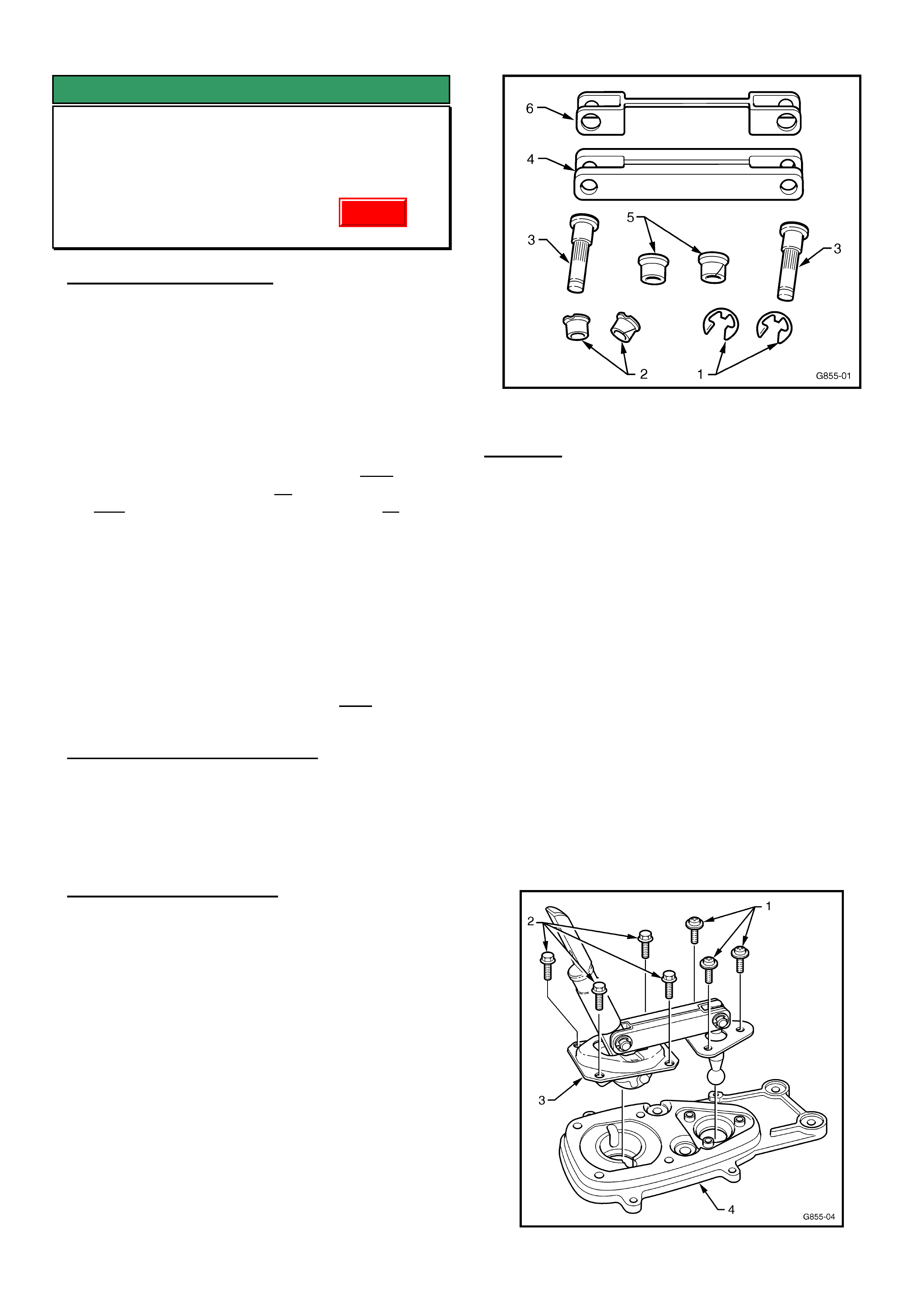
HOLDEN SERVICE TECHLINE______________________________________________________________NOVEMBER, 2003
21
SERVICE FIX
Gear Shift Lever Rattle/Buzz - (Shifter
Linkage Repair)
VTII, VX, VU, VY, V2, with Gen III & M/T
(GROUP 7A) TL608-0311
PROBLEM DESCRIPTION
Complaints may be received of gear shifter “rattle” at
various engine speeds/road speeds. Most common
complaints are from 3rd or 4th gears.
The condition is a “metallic rattle” which can be heard
by removing the gear knob/lever assembly, then
revving the engine in neutral with medium to heavy
throttle, above 2500rpm – as a quick diagnosis. The
shifter linkage rattle occurs mainly during heavy
acceleration in 3rd or 4th gear above 3000rpm. The
rattle is more prominent if you touch the back of the
gear knob with your finger in 3rd gear, or if you touch
the front of the gear knob with your finger in 4th gear.
It is recommended that this test be done with a known
non-rattling gear knob, so no confusion exists.
NOTE: the following procedure must not be carried
out until diagnosis and any necessary repair, as
described in Issue 11, November, 2003 Service
Techline for “Knob Rattle/Buzz” has been carried out.
EG: Where the Gear Lever & Knob Assembly has
been assessed and changed if necessary, and the
source of “gear lever rattle” has been defined as
coming from the shifter mechanism – NOT the lever
and knob assembly.
PRODUCTION RECTIFICATION
Revised shifter assemblies with anti-rattle feature, as
described in this bulletin, are to be introduced in
production shortly. When this occurs, the breakpoint
information will be included in the next Techline
Breakpoint Summary published.
SERVICE RECTIFICATION
Summary: Fit a Shifter Upgrade Kit as described
below.
NOTE: Upgraded “exchange” Shifters have been
supplied via TAS and HSPO since mid 2003 – These
parts do NOT need upgrading as described below,
and must not be upgraded or claimed for as warranty.
These exchange assemblies are identified by the
presence of either four red fibre washers between the
bridging piece and levers, or the black plastic “linked”
washers (6) shown below.
Bridging piece and related retaining parts (latest
types shown).
REMOVAL
1. Disconnect the battery earth lead.
2. Place gear lever in neutral.
3. Remove Gear shift knob/boot/lever assembly, and
centre console including the console cap - as per
the relevant procedures in Passenger SIP Sections
7B3 and 1A3 for the model vehicle being rectified.
4. Remove shifter cover and boot assembly by
removing the three Philips head screws.
5. Remove shift lever boot retaining plate:
Early build vehicles – remove the four bolts
securing the shift lever boot retaining plate,
from inside the vehicle, and lift off the plate;
Late build vehicles – remove the four nuts securing
the shift lever boot retaining plate to the floor pan
after raising the vehicle on a hoist. Front LH nut
access is limited, remove using an open end
spanner.
6. Remove the three self tapping screws (1)
retaining the front selector lever pivot assembly,
using a Phillips screwdriver – see Figure 1.
7. Remove the four hex head screws (2) holding the
rear selector lever pivot retaining plate (3), from
the baseplate (4) – see Figure 1.
Figure 1.
Update
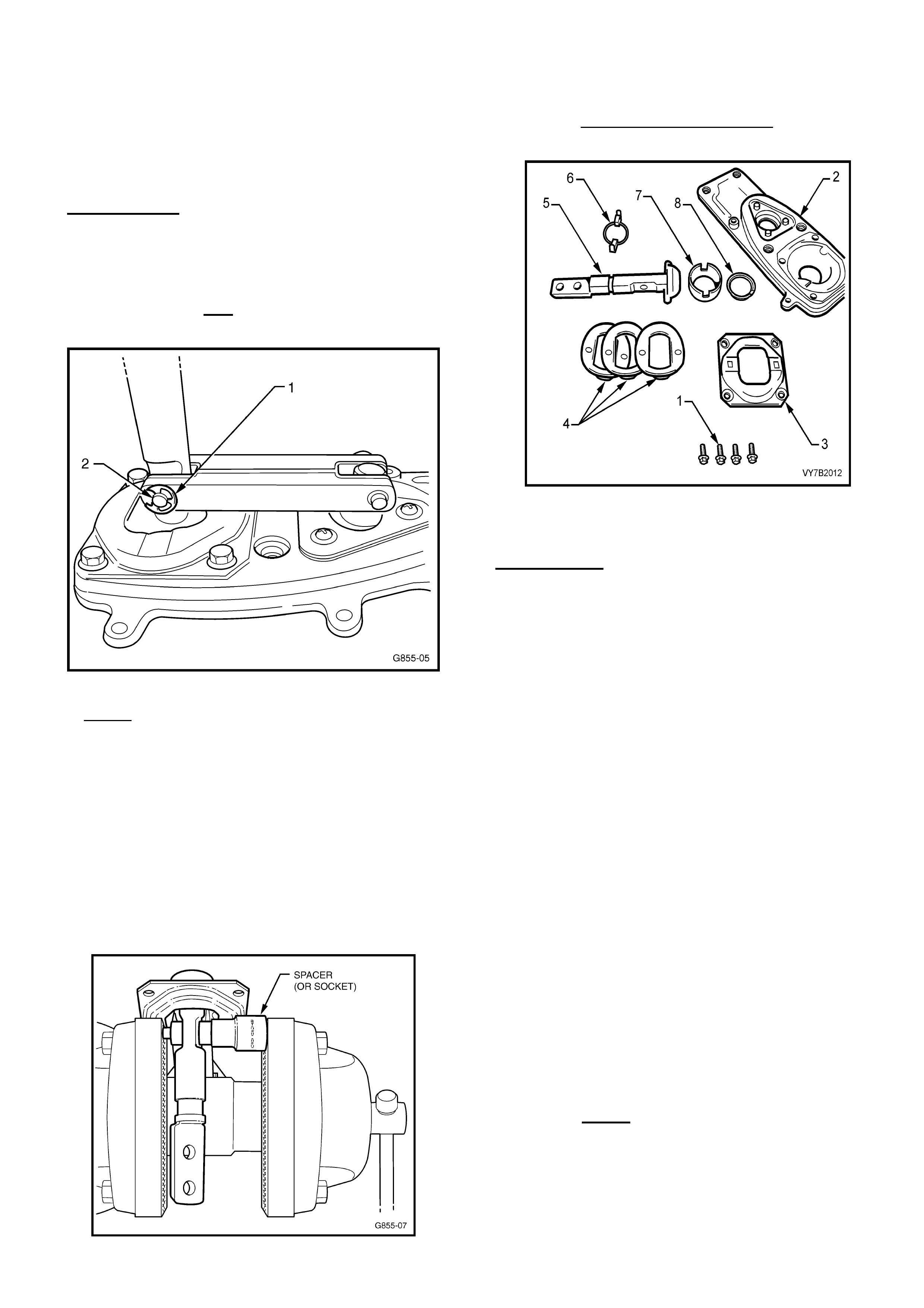
HOLDEN SERVICE TECHLINE______________________________________________________________NOVEMBER, 2003
22
8. Lift the front and rear selector levers and bridging
piece assembly up and out of the shifter base
plate (4) on the transmission, as shown in Figure
1. Ensure the ball seat (7) and seat support ring
(8) remain in the base plate (2) (these parts shown
in Figure 3).
DISASSEMBLE
CAUTION: During the disassembly process - wear
safety glasses to avoid possible eye injury.
1. Using a small flat bladed screwdriver, remove
circlip (1) from the rear lever/bridging piece retaining
pin (2) – see Figure 2.
Figure 2.
2. NOTE: BEFORE STARTING THIS STEP note
carefully the position and direction of the shifter upper
lever bolt holes and the shaft ‘cutaway’ for
reassembly! This determines the final position of the
gear lever, and gear knob direction! Refer Figure 5.
Tap or press the retaining pin – see Figure 2A - out of
the rear selector lever and bridging piece. This pin is
an interference fit into the selector lever, and may
need to be pressed out of the assembly. This can be
done by clamping the rear lever/pin in a vice, using a
spacer to fit over the pin head (if a suitable spacer is
not available, a suitable sized socket may be used).
Figure 2A. Rear Selector Lever Pin Removal.
3. After pin removal, retain the rear retaining plate (3),
the wave springs (4), and guide (6) shown in Figure 3
for re-use. Note the order of removal of the wave
springs and guide for re-assembly.
Figure 3 – showing rear selector shaft and rear
pivot components.
REASSEMBLE
Reassembly uses parts 1, 3, 4, 6, 7, 8 (in Figure 3)
and the following new parts in the Shifter Upgrade Kit,
• Front Selector Lever
• Front Selector Lever Retainer (triangular plastic)
• Front Selector Lever Retainer O-Rings (2)
• Rear Selector Lever
• Bridging Piece
• Anti-rattle “bridged” washers (black plastic)
• Pins
• small Bushes (blue plastic)
• Large Bushes (blue plastic)
• Circlips
CAUTION: During the reassembly process - wear
safety glasses to avoid possible eye injury.
1. Place the guide (6), wave springs (4) and rear
retaining plate (3) onto the new rear selector lever
(5) - shown in Figure 3 - in reverse order to their
removal.
Note: Apply 10% molybdenum disulphide grease
such as Molybond GA 10, or equivalent, to all
moving parts in the rear selector lever assembly.
2. Apply NLGI No. 4 EP grease to the new retainer
(triangular ball socket) of the new front selector
shaft, then assemble by hand, pushing the front
selector lever (1) into the plastic retainer (2) – see
Figure 6. NOTE: ensure the plastic ball retainer is
located with O-ring section toward the ball end of
the lever as shown in Figure 4 below.
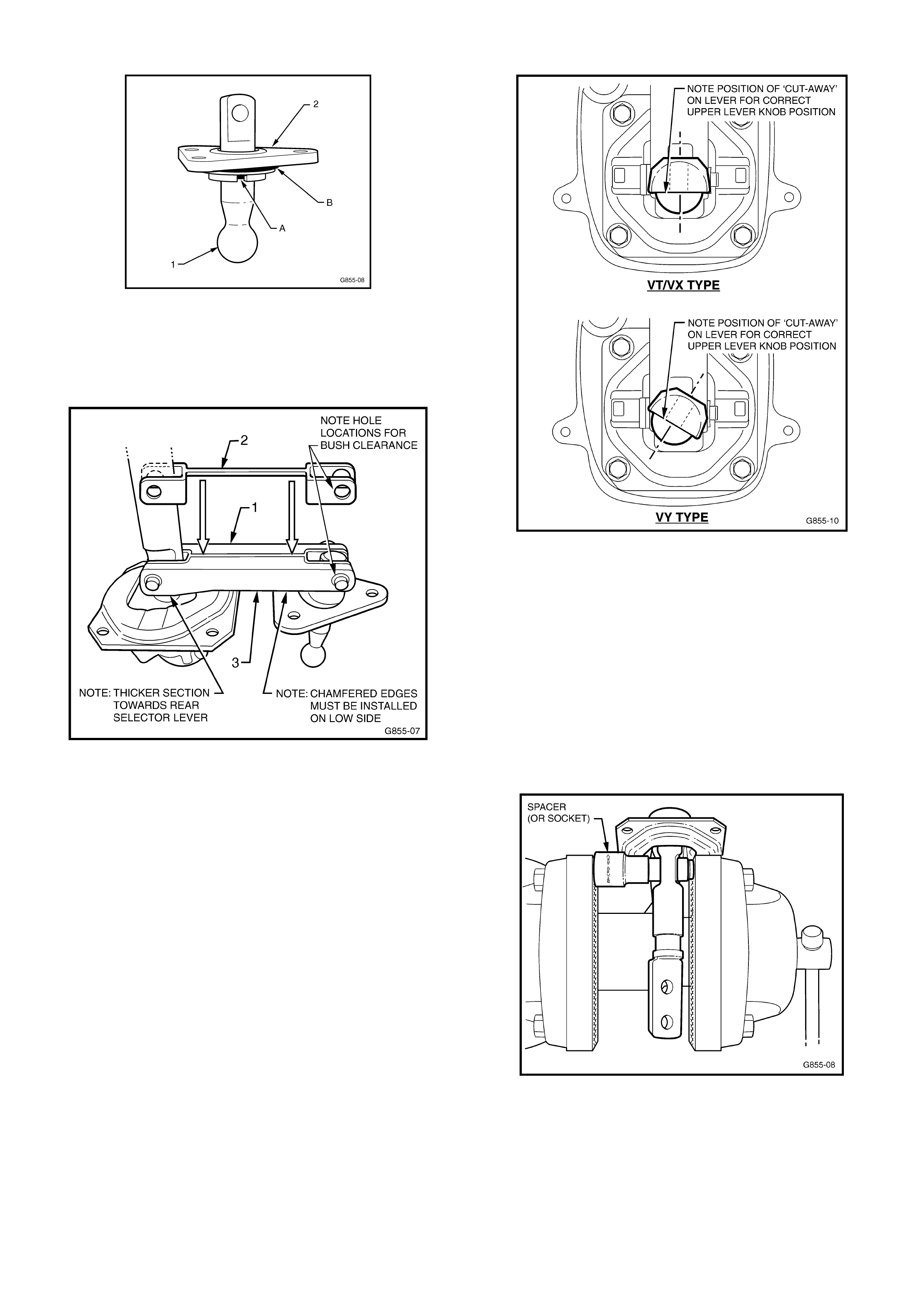
HOLDEN SERVICE TECHLINE______________________________________________________________NOVEMBER, 2003
23
Figure 4 – front selector lever and pivot.
3. Install the new “linked” anti-rattle washers (2) to the
new bridging piece (1) – refer Figure 5 below.
Ensure correct diameter holes match the holes in
the bridging piece.
Figure 5 – showing anti-rattle ‘linked’ washer
location.
4. Install the new (blue) bushes to the bridging piece
(outer) holes after lubricating with NLGI No. 4 EP
grease. Ensure the bushes are in the correct size
holes in the bridging piece/anti-rattle washers.
5. Install the new bridging piece assembly (3) to the
two new front and rear selector lever assemblies –
refer Figure 4 above. NOTE: Ensure that the rear
selector lever top retaining screw ‘cut-away’ and
holes are positioned the same way as when
removed from the shifter, and the chamfer on the
bridging piece is to the bottom, as shown in Figure 5
above. Figure 6 shows the correct location of rear
selector lever for both types of shifter:
Figure 6. Shows correct ‘cut-away’ and hole
locations.
6. Install new pivot pins to bridging piece/selector
levers and press home by clamping in a vice - use a
spacer to fit over the pin circlip grooved pin end and
blue bush (if a suitable spacer is not available, a
suitable sized socket may be used). Refer Figure 7.
NOTE: the pins fit easily into the bushes and
bridging piece holes, but are an interference fit into
the lever holes – after initial pressure to start the
pins into the lever holes – STOP - inspect the pin
installation for straightness - then complete the
pressing operation.
Figure 7. Selector Lever Pin Installation.
7. When the pin head butts up against the blue bush,
stop the pressing operation so that the bushes and
bridged washers are not damaged, then fit new
circlips (1) to secure each pin – refer Figure 8.
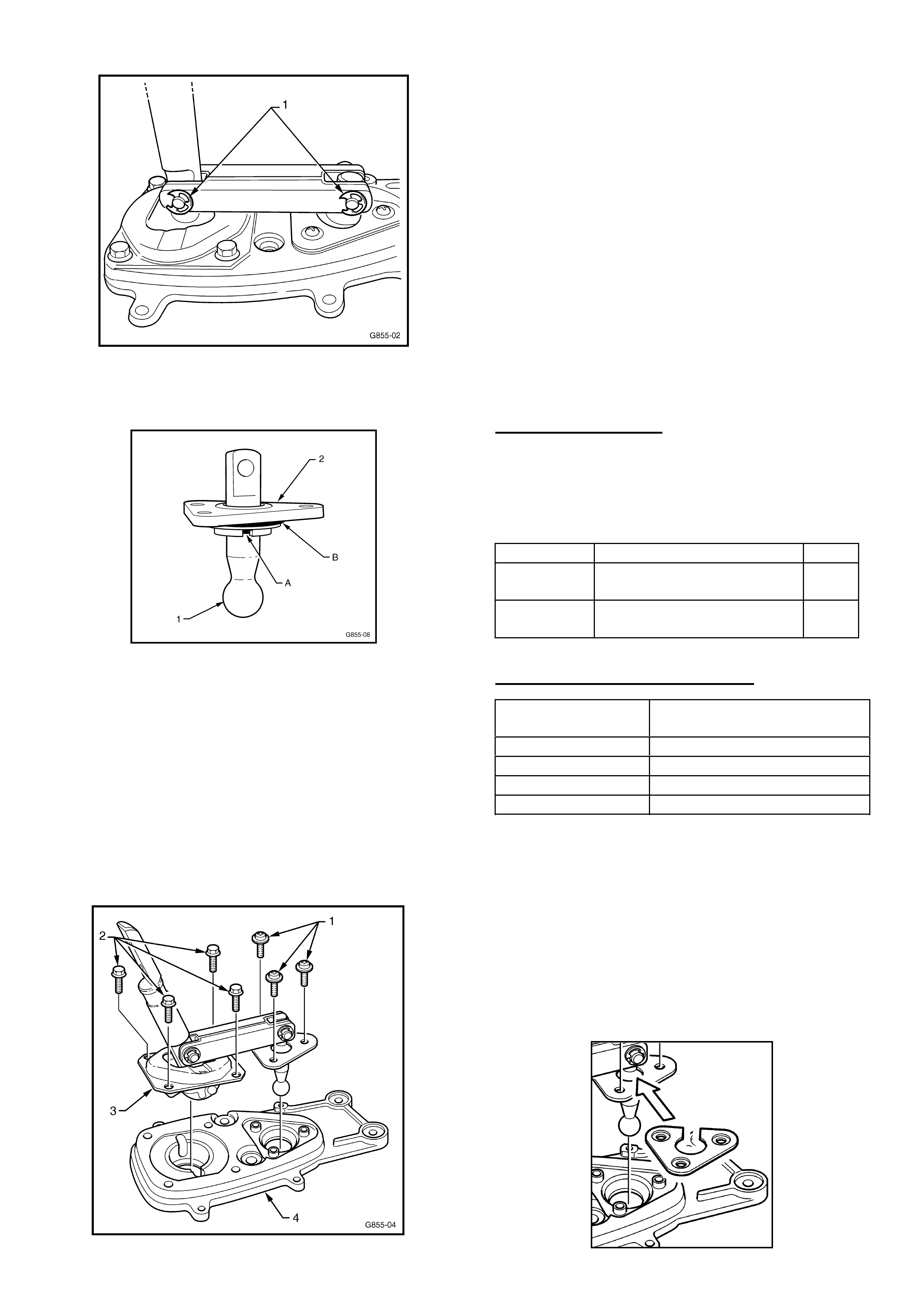
HOLDEN SERVICE TECHLINE______________________________________________________________NOVEMBER, 2003
24
Figure 8. – Circlips in final installed position.
8. Install new O-ring seals ‘A’ & ‘B’ to front selector
lever ball socket (2) – see Figure 9.
Figure 9 – front selector lever and pivot.
9. Reinstall the assembled bridging piece/selector
levers (3) into the base plate (4) on the transmission
and reinstall the four rear retaining plate bolts (2) –
see Figure 9 - tightening to the correct torque
specification: 10 –12 Nm.
10. Reinstall the front selector pivot assembly retaining
screws (1) to the baseplate (4) on the transmission
– see Figure 10 - tightening to the correct torque
specification: 5-8 Nm. Note: If a triangular metal
reinforcing plate was fitted to the shifter – refer to
Additional Information at the end of this Techline.
Figure 10.
11. Reinstall dust cover and boot assembly (4 screws)
to the remote shifter assembly on the transmission.
12 Reinstall the gearshift remote lever boot and plate
and secure to the floor pan as follows:
Early build vehicles – install the four bolts, from
inside the vehicle, tightening to the correct torque
specification: 6-14 Nm.
Later build vehicles - install the four nuts, with
vehicle raised on a hoist, tightening to the correct
torque specification: 15 Nm.
13 Reinstall the gear shift knob/boot/lever assembly
and console/console cap as per procedures in
Passenger SIP Sections 7B3 and 1A3 for the
relevant model.
14 Reinstall the battery ground lead.
PARTS INFORMATION
Use Figure 6 (above) for identification of the shifter
type fitted to the vehicle. To do this, remove the
console boot to determine the angle of the gear lever
retaining bolts and cut-away. Select the correct part
number kit as follows:
Part No.: Description: Qty
92147248 VT/VX type Shifter
Upgrade Kit
1
92147246 VY type Shifter Upgrade
Kit
1
WARRANTY CLAIM INFORMATION
Description Shifter Asm – Rattle
Upgrade
Labour Op. No K000294
Time 1.0 hr
Failure Code 28 rattle
Failure Code NOW K0028
Additional Information:
If a shifter assembly removed from a vehicle is fitted with
the triangular metal reinforcing plate shown below, the
triangular plate and retaining screws (which are longer
than standard screws) should be refitted to the shifter
assembly before reassembly Step 10 above. This action
is only as a precaution, as the new front lever pivot
(white plastic) is a stronger material than the original
part which makes fitting of triangular reinforcing plates
no longer necessary.