
2
20
00
03
3
S
SE
ER
RV
VI
IC
CE
E
T
TE
EC
CH
HL
LI
IN
NE
ES
S
©
2006 GM Holden Ltd. A.B.N. 84 006 893 232
Service Department
A “HOLDEN” Product.
BRISBANE SYDNEY MELBOURNE ADELAIDE PERTH
HOLDEN SERVICE TECHLINE_____________________________________________________ __________JANUARY, 2003
5
Spare Wheel –Soft Cover Staining
UBS Jackaroo & UES Frontera
(GROUP 10) TL410-0301
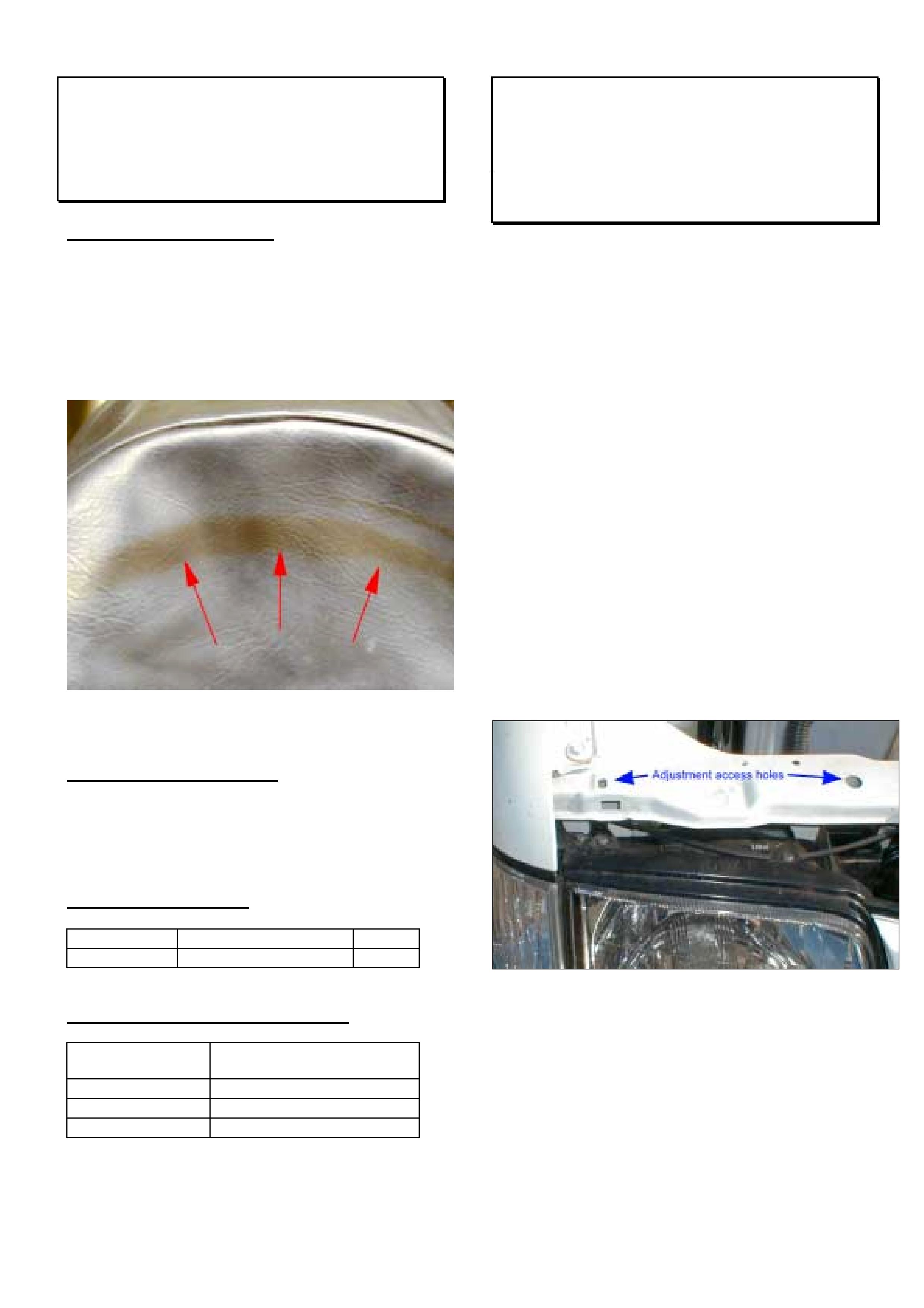
PROBLEM DESCRIPTION
Some customers may complain of stains appearing
on the outside of the soft spare wheel cover.
Investigations show staining can be caused by the
migration of anti oxidants from the tyre onto the PVC
cover.
Figure 1. Staining of spare wheel cover
SERVICE RECTIFICATION
On vehicles with above complaint, install plastic liner
part number 91151997 to the tyre prior to fitting a
new soft spare wheel cover.
PARTS INFORMATION
Part No.: Description: Qty:
91151997 sleeve - spare wheel 1
WARRANTY CLAIM INFORMATION
Description Spare wheel sleeve -
install
Labour Op. No. R000109
Time 0.2hr
Failure Code 78 discoloured
Headlamp Adjustment Procedure
TF Rodeo - LT, LT Sport and all Model
Year 2002
(GROUP 12) TL412-0301
This techline provides instructions for adjusting the
headlamp aim on the flush style lamps as there are
currently no instructions contained in the LCRV SIP
CD. These instructions will be included in a future
LCRV SIP update.
Adjustment Procedure.
To adjust headlamp aim, a Phillips No.2 screwdriver
with a minimum shaft length of 150mm and shaft
diameter no greater than 6.3 mm is required.
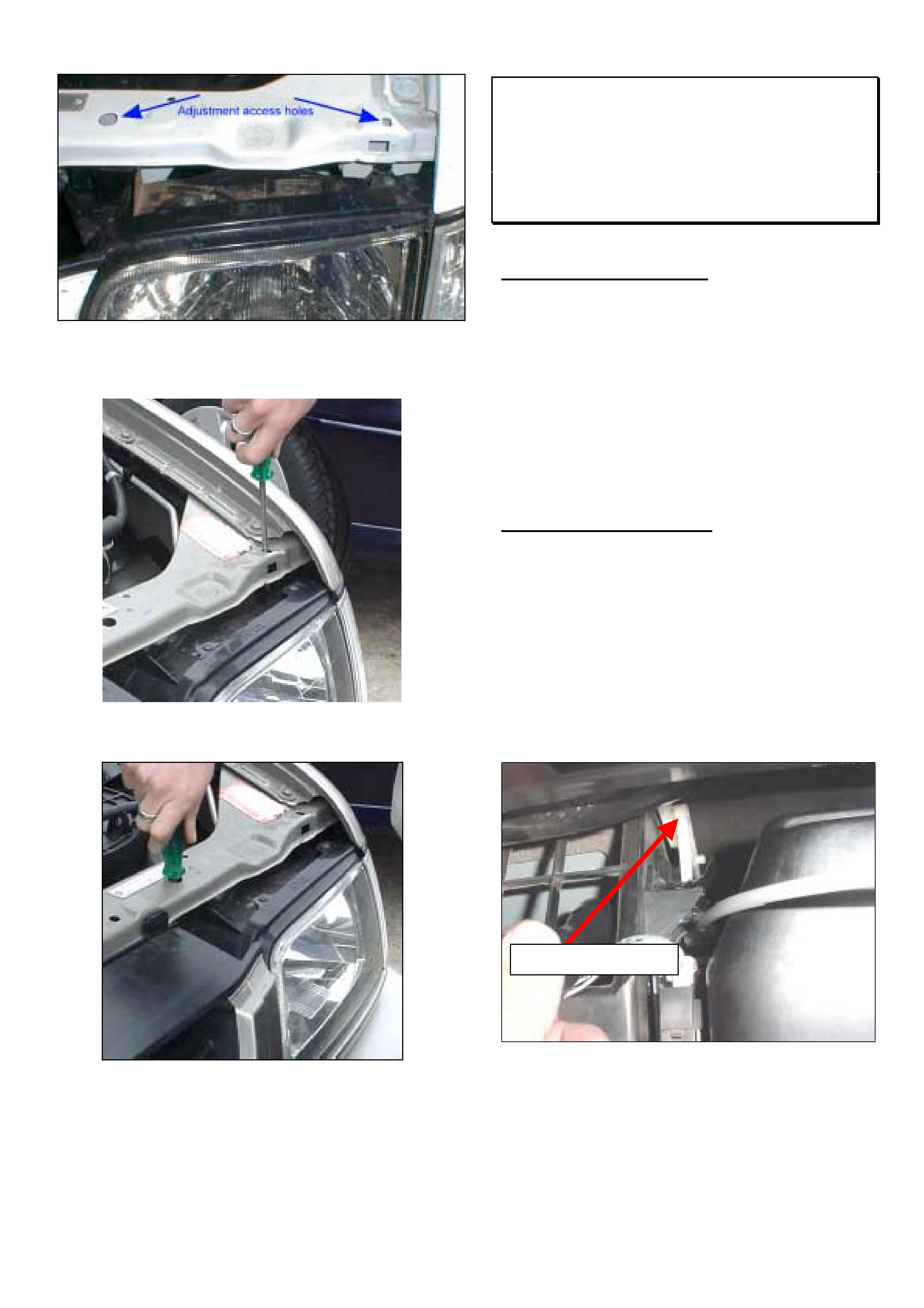
The adjusting mechanisms are accessed through the
holes shown in figures 1 and 2.
To adjust vertical aim use the outer hole as shown in
figure 3, insert the screwdriver so that it meshes with
the white gears of the adjustment mechanism and
turn the screwdriver to achieve the appropriate
movement.
For horizontal adjustment, use the inner hole as
shown in figure 4. Insert the screwdriver so that it
meshes with the adjuster gears and turn in the
required direction.
Figure 1. RHS adjustment access holes
HOLDEN SERVICE TECHLINE_____________________________________________________ __________JANUARY, 2003
6
Figure 2. LHS adjustment access holes
Figure 3. Vertical adjustment
Figure 4. Horizontal adjustment
HVAC Air Source Lever Moves While
Driving At Speed
TF Rodeo – Pre 03 MY
(GROUP 2) TL391-0301
PROBLEM DESCRIPTION
Customers may report that the HVAC air source lever
moves from the re-circulate position to the centre
position while driving. This is most likely to occur
when driving at 80km/hr or above, passing on-coming
trucks or driving with the window down.
Investigation of affected vehicles has found that the
air source cable has been incorrectly adjusted in
production. This does not allow the lever to detent at
the HVAC unit.
SERVICE RECTIFICATION
Complete the adjustment procedure below to obtain
full detent operation.
1. Remove the glove box hinge screws and glove
box.
2. Disconnect the air source flap cable at the
retaining spring.
3. Move the air source control lever (on the dash)
fully to the re-circulate position.
4. Push the air source flap linkage (behind the glove
box) as indicated in figure 1.
Figure. 1
Note: Pushing directly on the air source flap does not
locate the vent correctly.
Apply Pressure Here
HOLDEN SERVICE TECHLINE_____________________________________________________ __________JANUARY, 2003
7
5. Pull gently on the control cable while installing
into the retaining spring, this will ensure good
adjustment is achieved.
Note: The air source control lever and linkage must
remain in the correct position while installing the control
cable.
6. Check that the air source system has full
movement.
7. Reinstall the glove box.
WARRANTY CLAIM INFORMATION
Description Cable Adjustment – Air
Source Lever
Labour Op. No. D000342
Time 0.3 hr
Failure Code 26 Misadjusted
Door Lock Knobs Rattle
YG Cruze
(GROUP 1) TL414-0301
PROBLEM DESCRIPTION
Some customers may complain of a rattle noise from
door trims in the door lock knob area.
Investigations show this condition is caused by
insufficient retention of the door lock knob cap in the
door trim which results in a rattle.
PRODUCTION RECTIFICATION
Door trims with improved retention of knob cap
(dimension A increased) have been fitted to vehicles
from:
ISOVIN: Build Date:
JSAGHY81S00110001 3/09/2002
SERVICE RECTIFICATION
Summary: On all 4 doors, glue door knob cap to
door trim as per following procedure.
1. Remove door trim from each door by referring to
instructions in LCRV SIP. Select: Section 9 –
Body Service / 2 – Body Structure / 2.1 – Front
door asm. OR 2.2 – Rear door asm.
2. Note which way the knob cap is oriented in the
door and then remove it from the door trim by
pushing down hard on cap or carefully levering
with a screw driver from the flared side of the
cap.
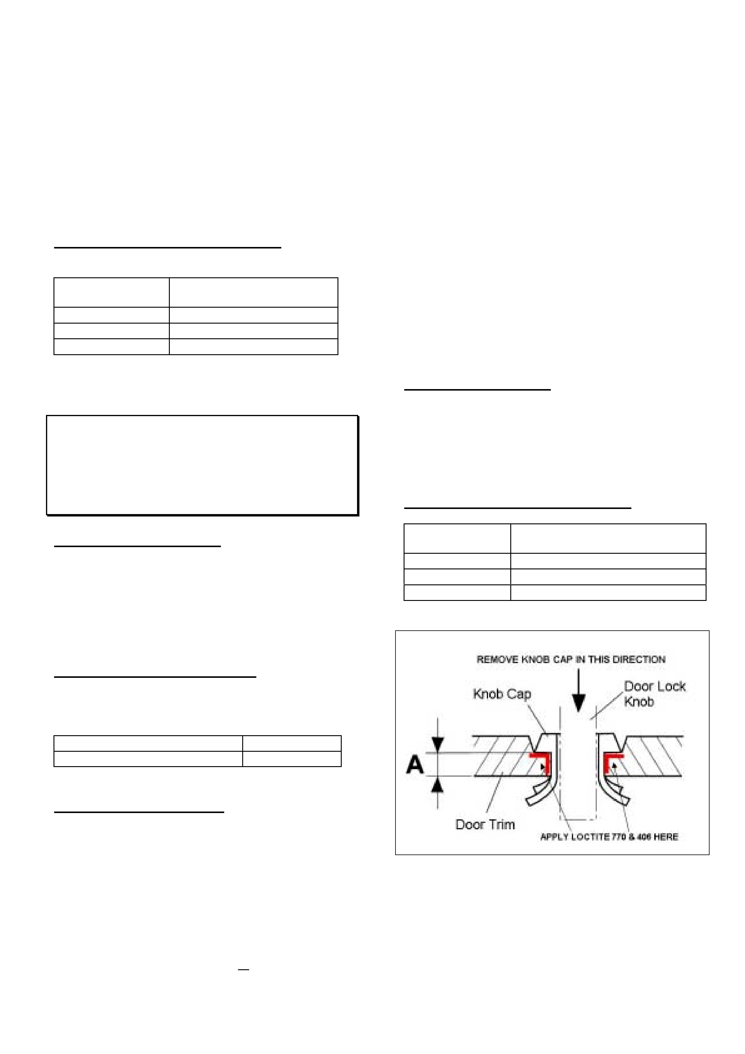
3. Apply LOCTITE 770 Primer (or equivalent) to
both knob cap and door trim where these parts
touch – Refer Figure 1. NOTE: Take care NOT
to apply primer to areas of knob cap or door trim
which are visible by customer. Allow to dry
according to manufacturers instructions.
4. Apply a very small amount of LOCTITE 406 (or
equivalent) instant adhesive to those areas on
the knob cap and door trim where primer has
already been applied. Applying with toothpick-
sized object prevents excessive adhesive being
used.
5. Immediately insert knob cap back into door trim
using correct orientation of knob cap.
6. Allow to cure for 30 seconds.
7. Reinstall door trim into vehicle.
PARTS INFORMATION
LOCTITE 770 (Activator - Polyolefin Primer) and
LOCTITE 406 (Instant Adhesive - Prism) are both
available from most Industrial suppliers such as BSC,
CBC, Blackwoods, etc.
WARRANTY CLAIM INFORMATION
Description Remove door trim and glue
door lock knob cap – All doors
Labour Op. No. C000479
Time 0.9 hr
Failure Code 28 rattle
Figure 1.

HOLDEN SERVICE TECHLINE____________________________________________________________FEBRUARY, 2003
12
Radio Lock Up
UBS Jackaroo / TF Rodeo / UES Frontera
with Eurovox Radios
(GROUP 12) TL406-0302
PROBLEM DESCRIPTION
Customers may advise that they have experienced a
“lock up” condition of their radio. In this condition, the
radio will not operate and the screen is blank when
presented to the Retail Outlet.
NOTE: These radios will normally go into lock up
mode as a protection from a high voltage condition.
SERVICE RECTIFICATION
When investigating a complaint of radio lock up
condition it is recommended that you disconnect the
radio from battery power for at least one hour then re-
enter the radio pin number and re-evaluate the
operation of the radio. This can be done by either
disconnecting the vehicle battery or removing the
radio from the dash.
If the radio still fails to operate then proceed with
normal repair/replacement procedures.
HOLDEN SERVICE TECHLINE__________________________________________________________________MARCH, 2003
6
INFORMATION
SERVICE TECHLINES “ON-LINE”
(GROUP 0B) TL458-0303
Service Techlines are available “on-line” at Retailers through the “Holden Lionheart Portal”. The latest Techlines can
be viewed “on-line” immediately they have been approved for publication which means that you can have the latest
Techline information about 2 weeks earlier than you currently receive it. Note; two weeks is about the minimum
period of time it takes to print and distribute Techlines to Retailers via the Technicians Guild program or by direct mail
to Service Managers.
As Techlines are currently prepared on a monthly cycle it is suggested that you check for new bulletins at the
commencement of each month.
The Holden Lionheart Portal should be available on your Sales/Stock Controllers computer and should soon be on
most warranty clerks computers to allow them to access the new On Line warranty system due mid 2003. In order to
have the Holden Lionheart Portal installed on your Service Departments computer you will need to get the necessary
approval from your Retailer’s IT systems administrator.
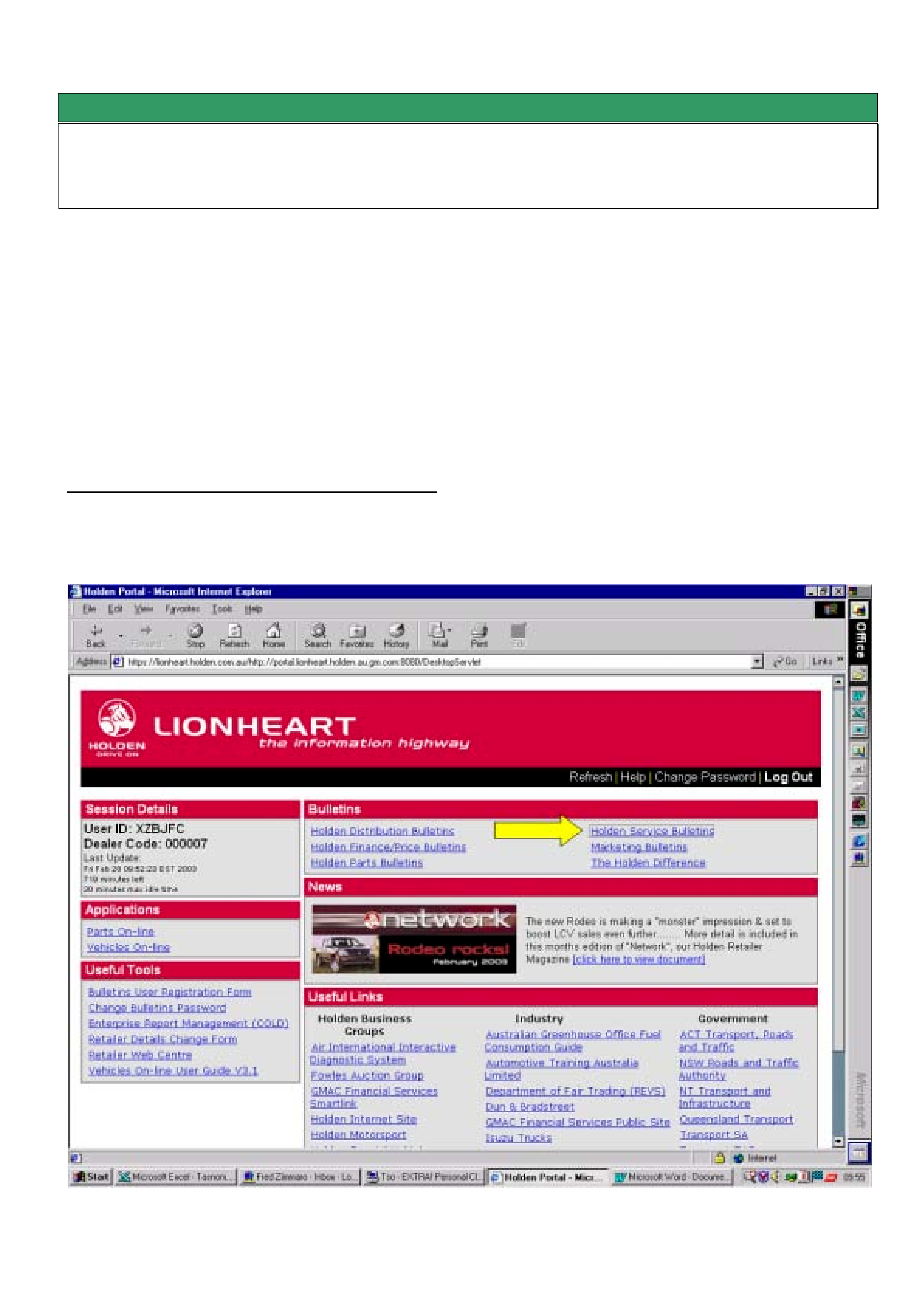
Procedure For Viewing Service Techlines On Line.
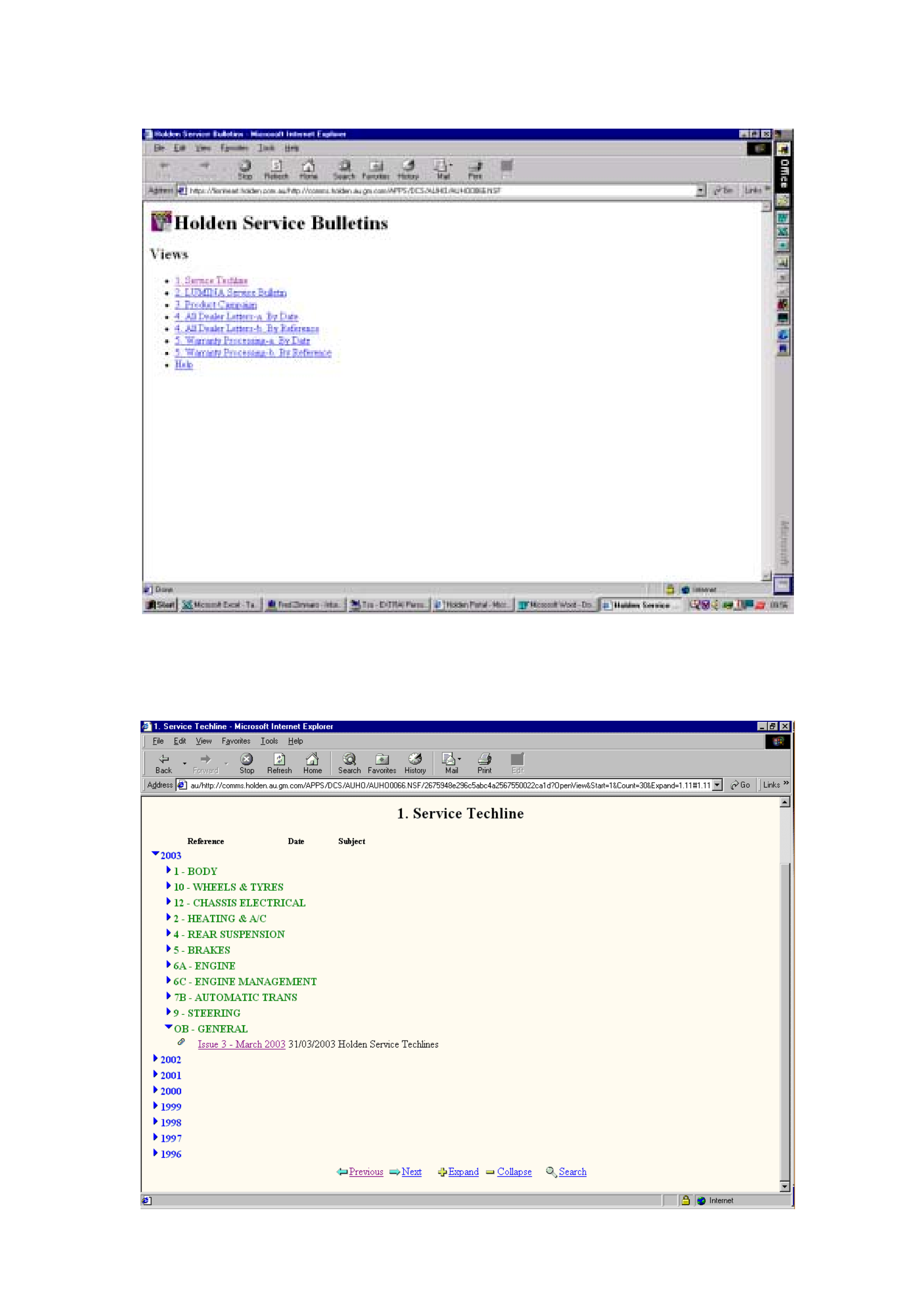
Step 1. When the Holden Portal is accessed via Microsoft Internet Explorer the first screen to appear is as follows.
From the section titled “Bulletins” select Holden Service Bulletins.
HOLDEN SERVICE TECHLINE__________________________________________________________________MARCH, 2003
7
Step 2. The next screen to appear is as follows. Select “1. Service Techline”. As you can see from this screen you
can also access other Service information such as Product Campaign Bulletins, All Retailer Letters etc.
Step 3. The next screen to appear is as follows. Select Group OB – General and look for the latest Issue number.
You can then open the file provided you have Acrobat Reader software installed. As Service Techlines are currently
prepared on a monthly cycle it is suggested that you check for new bulletins at the commencement of each month.
HOLDEN SERVICE TECHLINE__________________________________________________________________MARCH, 2003
8
SERVICE PROCEDURE
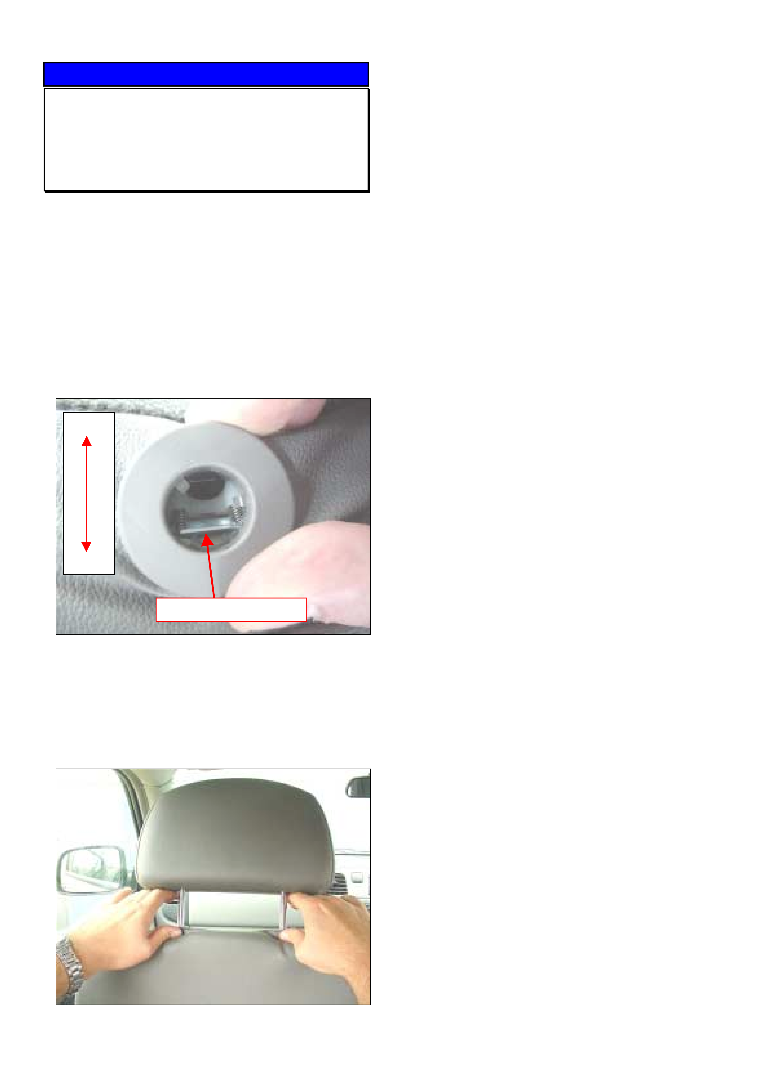
Head Restraint Removal Procedure
RA Rodeo
(GROUP 1) TL455-0303
Retailers have reported difficulties when removing
the head restraint.
Head restraint adjustment is achieved by simply
moving the head rest up or down as required.
However, to remove the head restraint it must be
disengaged whilst in the highest position.
The locking mechanism that prevents the head
restraint being removed is located at the rear of the
white guide immediately under the seat trim. Refer
Figure. 1.
Figure 1.
Note: The release latch must be pressed directly as
there is a solid block below the latch.
Depress both release latches simultaneously while
moving the headrestraint upwards to remove as
shown in Figure 2.
Figure 2.
Press Release Latch
Front
Rear

HOLDEN SERVICE TECHLINE_________________________________________________________________ APRIL, 2003
INFORMATION
Seat Belts Replaced For Complaint Of
Not Extending
UES Frontera, YG Cruze, RA Rodeo
(GROUP 1) TL253A-0304
This Techline supercedes the previous one in Issue
4, May, 2002. It is revised by adding YG & RA
models.
PROBLEM DESCRIPTION
Numerous seat belts returned through the warranty
system cannot be faulted. The reason for
replacement of these belts is given as "seat belt will
not extend" or "seat belt jamming".
It appears that customers and Retailer staff may be
unaware of the Auto Locking Ratchet (ALR) system.
Refer to following for explanation of ALR.
Automatic Locking Ratchet (ALR) Mechanism.
The rear outer seat belts (all rears on RA Rodeo) and
left hand front seat belt have an Automatic Locking
Ratchet (ALR) mechanism. When this mechanism is
activated it will only allow the belt to retract. When
the mechanism is de-activated the belt can be
extended or retracted as normal.
To activate the ALR mechanism, extend the seat
belt to its maximum length.
To de-activate the ALR mechanism, allow the seat
belt to retract fully.
The ALR function may be useful as an additional
means of locating a child seat, when used in
conjunction with the approved child restraint anchor
points.
Note: It is always better to install a child restraint in
the rear seat.
SERVICE RECOMMENDATION
To avoid mis-diagnosis of seat belts, Holden Retailer
frontline staff should familiarise themselves with the
operation of the ALR system . They will then be able
to explain this feature to any customers who
complain that their seat belts “will not extend” or are
“jamming”.
NOTE: Seat belts replaced unnecessarily for
complaint of “not extending” will not be accepted as
warranty.
SERVICE FIX
LSD Shudder/Chatter Noise
Jackaroo, TF & RA Rodeo, Frontera
(GROUP 4) TL442-0304
PROBLEM DESCRIPTION
There have been some reports to TAS and in PIRs of
rear Limited Slip Differential (LSD) chatter on the
Light Commercial Vehicle (LCV) range.
These vehicles all use similar types of LSD and share
the same factory fill of API GL5 LSD Oil, which
contains additives to reduce the amount of chatter
from the differential arising from normal operation.
NOTE: Normal operation of these LSD's will produce
some noise. They are designed so that the amount
of differential movement between the two axle halves
is limited by the use of pre-loaded multiplate clutches.
This means that until the torque difference limit of the
clutches is reached, any differential movement
between the wheels will be taken up by slippage of
the tyres, resulting in noise. When the torque
difference reaches the limit, the clutches may
experience a stick/slip condition resulting in noise.
This will be particularly noticeable on cornering under
power during takeoff etc.
SERVICE RECTIFICATION
Summary: On complaint vehicles add Friction
Modifier Additive to rear axle.
If an owner complains of differential noises that are
caused by LSD operation and the differential oil is of
the correct specification and has not been
contaminated it is recommended to add LSD friction
modifier additive (P/N 1052358) to reduce the noise.
On vehicles that have done 10,000km or less
since last rear axle oil change- the additive can be
poured directly into the differential housing. It may
first be necessary to ensure enough capacity in the
housing by draining approximately 120ml of oil from
the rear axle.
On vehicles that have done more than 10,000km
since last rear axle oil change - drain the
differential when warm. Then pour in the additive and
fill the differential with the specified lubricant.
Friction Modifier Run-in. The friction modifier
requires a run-in to work the additive into the clutch
plates. This can be done either by normal driving
(may take up to 1000 kms), or alternatively, the
Retailer or customer may perform up to 10 minutes of
figure 8 driving on a hard flat surface.
Update
HOLDEN SERVICE TECHLINE_________________________________________________________________ APRIL, 2003
PARTS INFORMATION
Part No.: Description: Qty:
1052358 Additive-friction
modifier for LSD oil
120 ml.
1
WARRANTY CLAIM INFORMATION
Use the following information if submitting a warranty
claim.
Description Add friction modifier to LSD
Labour Op. No. F000188
Time 0.3 hr
Failure Code 40
INFORMATION
White Marks On Interior Trim
All Models
(GROUP 1) TL468-0304
PROBLEM DESCRIPTION
There have been some dash trims returned to
REPAC that were replaced for exhibiting white stains.
Investigation has found that these stains are in areas
where customer hands are likely to contact the trim.
In all cases the stains were able to be removed using
dish washing liquid diluted with water.
HOLDEN SERVICE TECHLINE_________________________________________________________________ APRIL, 2003
SERVICE PROCEDURE
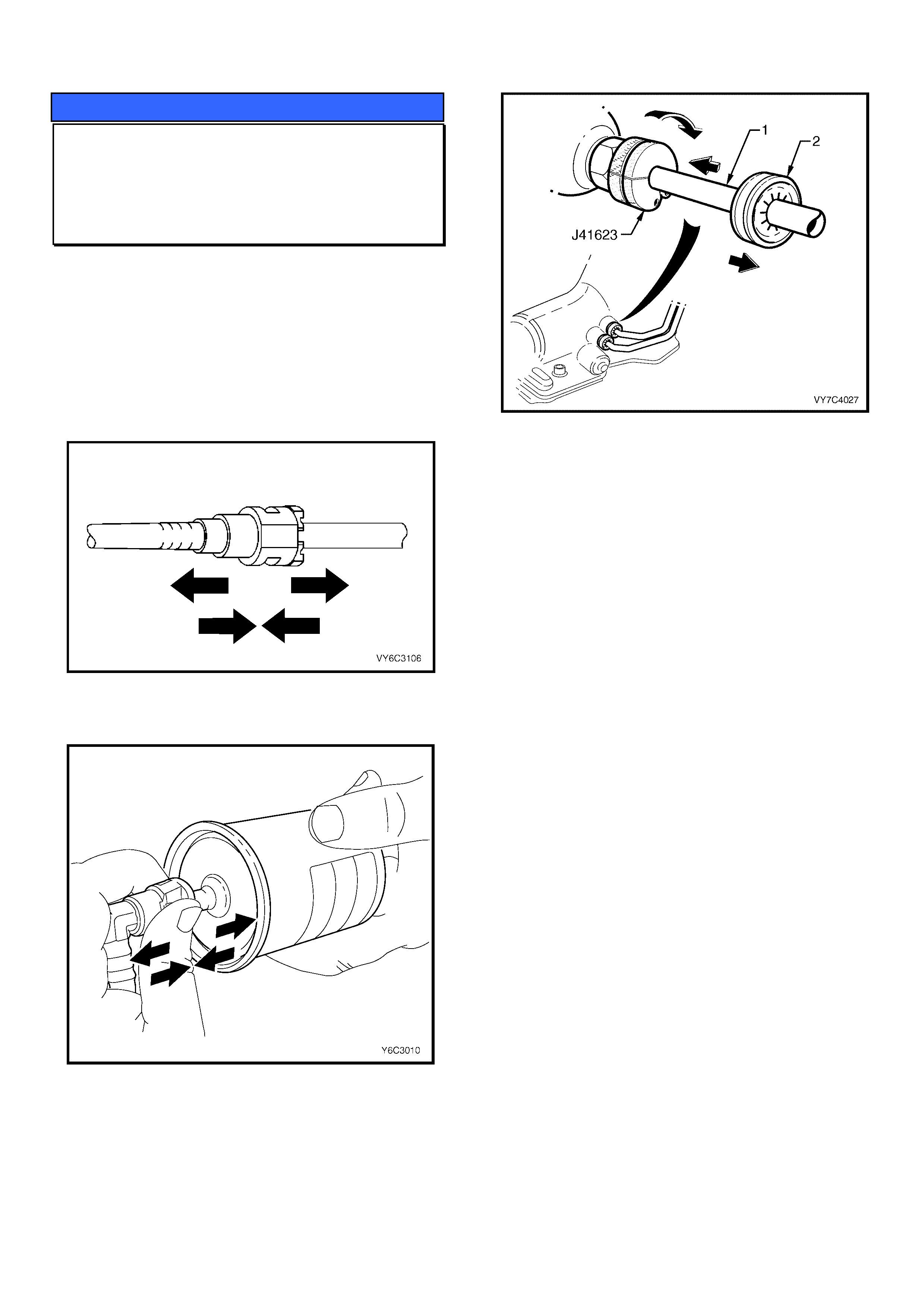
Quick Connect Fittings
All
(GROUP OB) TL466-0304
The purpose of this techline is to remind technicians
of the importance of always checking quick connect
fittings after reconnection. This is normally done by
pushing/pulling on both sides of the fitting.
Refer to the following drawings from PV SIP which
shows the checking method for some of the different
types of quick connect fittings.
Figure 1. Fuel line fitting (Plastic collar type)
Figure 2. Fuel filter fitting.
Figure 3. 4L60E Auto Trans Cooler lines.
To check A/T cooler pipe quick connect fittings after
reconnection, attempt to pull the pipe free. A 2nd
check is to slide each verifier disc (#2) up to the
fitting. If it engages with the fitting then the pipe has
been correctly installed. NOTE the verifier disc
should be left in this position.
(NOTE; figure 3 shows the quick connect removal
tool J41623 in position)

HOLDEN SERVICE TECHLINE_________________________________________________________________ APRIL, 2003
SERVICE FIX
TURBO (SHAFT) FAILURE
UBS JACKAROO with 4JX1 DIESEL
ENGINE
(GROUP 6A) TL430-0304
This Service Techline supersedes the previous
Techline on this topic (Issue 7, 2001 page 12). The
previous Techline should be destroyed.
PROBLEM DESCRIPTION
The engine loses power and emits an abnormal
amount of smoke.
PRODUCTION RECTIFICATION
A revised turbocharger assembly has been
developed with an increase in impeller diameter
which allows the turbo to do the same work at a lower
speed.
PRODUCTION BREAK POINT
The revised turbo was introduced with the Euro 3
compliant engine at the B/P below.
ISOVIN: Build Date:
JACUBS73G27106468 09/01/03
SERVICE RECTIFICATION
Fit a new turbo assembly to any vehicle presented to
your dealership that has a failed turbo assembly.
When fitting a new turbo you must:
1. To prevent further bearing failures, confirm that
the injector sleeve replacement has been carried
out on the vehicle if required (refer All Retailer
Letter RL 72/02).
2. Never run the vehicle before priming the
turbo bearings with oil and, never run the
vehicle with the oil supply to the turbo
disconnected.
3. Check the oil supply to and from the turbo before
fitting the new turbo assembly. Disable the
vehicle by disconnecting the cam sensor and
check oil supply at cranking speed. Oil flow tests
are easier to complete with the failed turbo
removed.
The following are approximate values to use as a
guide only. Oil viscosity, temperature, battery
condition, etc, will cause results to vary between
vehicles.
• Oil should flow from the turbo feed pipe
within approx. 7 seconds of cranking;
• Approximately 25ml of oil should flow from
the turbo lubrication feed pipe for every 1
second of cranking (once the oil flow has
commenced);
• Check the oil return from the turbo to the
crank case. When oil is poured into the return
hose it should flow freely into the crank case.
4. Prime the turbo by adding 100ml of oil to the
turbo oil lubrication inlet. Rotate the turbo shaft
slowly by hand, this will ensure the turbo bearings
are lubricated at initial start up.
Detailed fitting instructions for removal and
installation of the turbo unit are in LCV SIP. Once in
SIP follow the path:
! UBS Jackaroo
! Engine – 4JX1
! Section 6A – Engine Mechanical
! Engine Assembly
! Turbocharger
PARTS INFORMATION
Part No.: Description: Qty:
8973125140 Turbo Assembly 1
WARRANTY CLAIM INFORMATION
Use existing warranty information in LCV SIP as
below.
Description Turbo Asm - Replace
Labour Op. No. J586300
Time 2.2 hr
Failure Code 85

HOLDEN SERVICE TECHLINE___________________________________________________________________ MAY, 2003
6
INFORMATION
Air Conditioning Kit Fitment Concerns
RA Rodeo
(GROUP 2) TL492-0305
It has come to Holdens attention that on some
vehicles the air conditioning kits have not been fitted
in accordance with the manufacturers fitting
instructions.
The short cuts which are being taken, together with
poor fitting practices will have a detrimental effect on
A/C performance and ultimately lead to customer
dissatisfaction.
Some of the deficiencies observed on recent
installations are as follows.
1. Condensor lower seal not fitted.
2. Suction line retaining bracket not fited
3. Evaporator drain hose not fitted.
4. Styrene liner not fitted to inside of evaporator
lower case.
5. Thermister wire routed incorrectly.
6. Condensor fan bolts loose. (Removing fan is not
part of fitting procedure)
7. Incorrect refrigerant charge. (Believed to be
caused by use of smaller than required aerosol
charging can)
IMPORTANT: Warranty on the A/C kit may be voided
if failures can be attributed to kits not being fitted in
accordance with the manufacturers instructions.
Please ensure that if you are fitting A/C kits in your
Retailership that you follow the Manufacturers fitting
instructions.
Fitting instructions for RA Rodeo A/C kits were
mailed to all Retailers in March 2003.
If you require additional copies they can be
purchased from HSPO using the following part
numbers.
Part No. Description
61388910 A/C Fitting Instructions for engine
6VE1
61388898 A/C Fitting Instructions for engine
4JH1
61388906 A/C Fitting Instructions for engine
C24SE
Fitting instructions are also available on the latest
Light Commercial & Recreational Vehicle SIP CD.
DIAGNOSIS HINT
Hard To Start or Lack of Engine
Response (Intake Throttle Valve Sticking)
Jackaroo Diesel 4JX1
(GROUP 6C) TL489-0305
This Techline is repeated from Jan 2001 in response
to a query raised at the April 2003 Queensland SMA
Foremans meeting.
PROBLEM DESCRIPTION
Some 4JX1 engines may with time, develop condition
of “Hard to Start” and/or “Lack of Engine Response
Under Acceleration.”
DTC 1486 (Intake throttle position sensor high
voltage) will usually be set. The check engine light
may also be illuminated.
The problem may disappear once the engine has
warmed up to normal operating temperature.
Possible Cause.
The above conditions can be caused by the Intake
Throttle Valve sticking due to an excessive build up
of carbon.
NOTE: It is normal for the 4JX1 engine to experience
some acceleration lag when cold due to oil viscosity.
SERVICE RECTIFICATION
Summary: Confirm complaint. Perform diagnosis as
per SIP. Clean Throttle Valve.
Procedure.
After confirming the complaint condition, conduct a
thorough diagnosis as per procedures found in Light
Commercial SIP CD via following path:
4JX1 Engine / Section 6D3 - 3.0L Engine Driveability
& Emissions / Symptom Diagnosis / Hard Start,
Lacks Power etc.
If this diagnosis fails to rectify the condition, remove
the Throttle Valve Assembly and thoroughly clean
any carbon buildup which may be causing the intake
throttle valve to stick.
IMPORTANT: Do not remove or immerse the Throttle
Valve Sensors into any form of cleaning agent.
HOLDEN SERVICE TECHLINE___________________________________________________________________ MAY, 2003
7
INFORMATION
Oil Level Checking At PD
TF and RA Rodeo With 4JH1-TC Diesel
Engines
(GROUP 6A) TL498-0305
PROBLEM DESCRIPTION
Engine oil level is reported as low when checked
during the PD inspection.
OIL LEVEL CHECKING PROCEDURE
When checking the engine oil level it is crucial that
the engine oil is at running temperature (hot to
touch). The vehicle must be on level ground and the
engine oil allowed to settle for a few minutes.
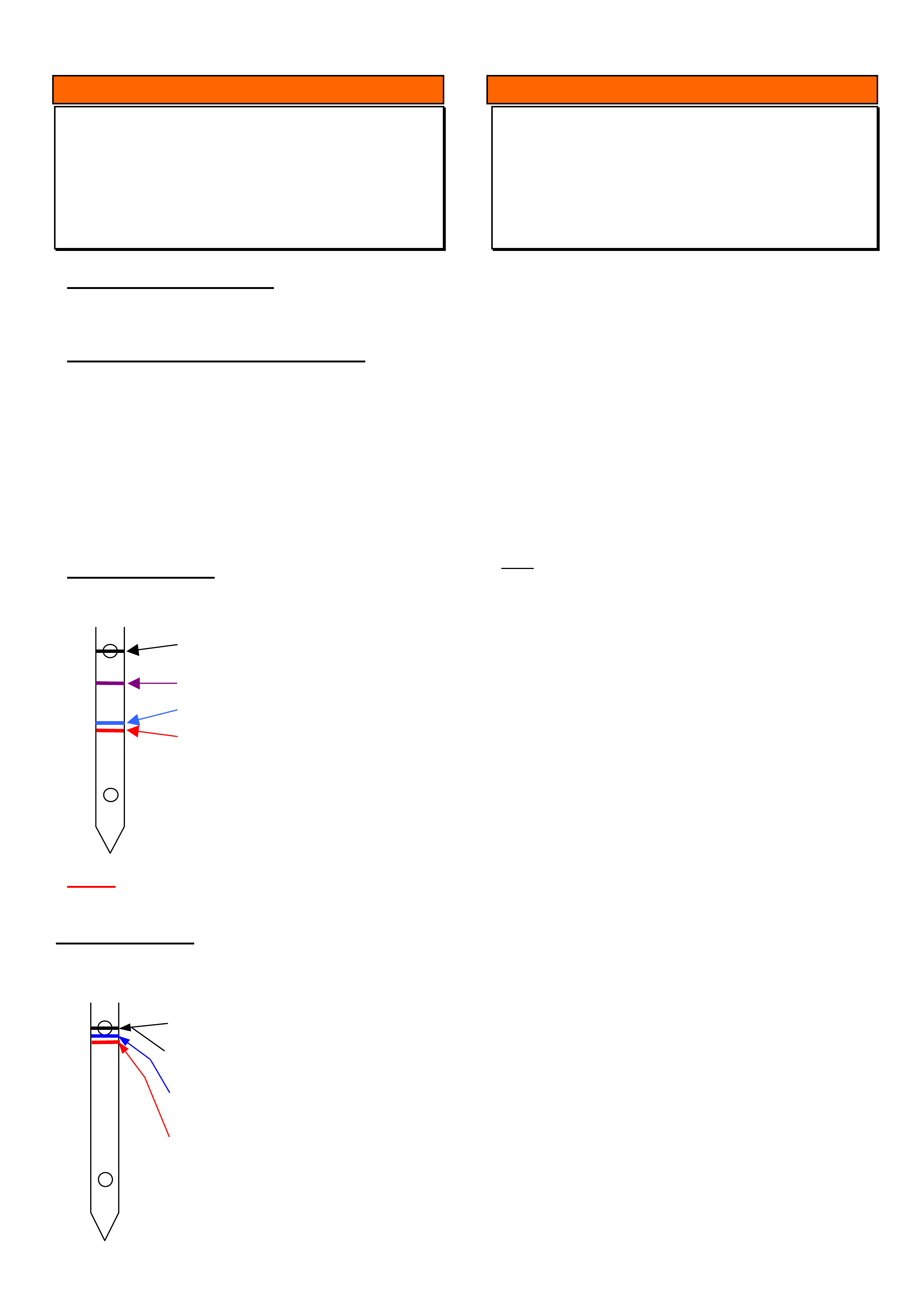
The diagrams below give an indication of how the oil
level will settle after being left for a specified length of
time when the oil is hot and cold.
Note: Oil level was full at the start of each test
Cold Oil Checking – Not Recommended
Vehicle driven for 5 minutes from cold then engine oil
left to settle.
NOTE: The oil level did not completely recover to
the full mark, even after 24hrs.
Hot Oil Checking - RECOMMENDED
Engine run until the oil is at operating temperature then
allowed to settle.
INFORMATION
Remote Central Door Locking Operating
Logic
RA Rodeo
(GROUP12) TL493-0305
The operating logic of the central door locking system
in RA Rodeo is different to other Holden vehicles as
is evident in the following explanation.
If the central locking is activated from inside the
vehicle using the switch on the dash or on the driver's
door (where fitted) to lock all the doors and a door is
then unlocked using the snib on the door, the remote
key will not lock the vehicle until the Remote unlock
button is first pressed to unlock all doors.
The Remote lock button will then activate the central
locking.
The RA Rodeo Owners Handbook will be revised at
the next reprint in line with the above.
Note: Other Holden vehicles will activate the central
locking regardless of the snib position on each
individual door.
Oil level before
Oil settled for 10 min
Oil settled for 3 min
Oil settled for 5 min
Oil level before startin
g
Oil Level Before startin
g
Start
Oil settled for 1 hour
Oil settled for 3 min
Oil settled for 5 min

HOLDEN SERVICE TECHLINE___________________________________________________________________ MAY, 2003
8
INFORMATION
Electronic Odometer Programming
UBS / UES / RA
(GROUP 12) TL481-0305
PROBLEM DESCRIPTION
When a replacement instrument cluster is installed
into a UBS Jackaroo MY98 onwards, a UES Frontera
MY01 onwards or RA Rodeo, it is necessary to
program the odometer to the value of the one
removed.
SERVICE RECTIFICATION
If your Service Department does not know of any
instrument repairers who are capable of performing
this operation below are some contacts of instrument
repairers presently being used by other Retailers.
Victoria
Automotive Instrument Repairs
59 C Glenvale Crescent,
Mulgrave, Victoria 3170
Phone (03) 9561 2366
Fax (03) 9562 2513
NSW
Macarthur Instruments
Unit 2/16 Cawdor Road
Camden, NSW 2570
Phone (02) 4655 3335
Mobile (0416) 241 903
Web site www.macarthurinstruments.com.au
QLD
Future Auto Instruments
P.O. Box 959
Paradise Point QLD 4216
Phone (07) 5529 5325
Fax (07) 5529 5065
Mobile (0414) 518 766
New Zealand
Robinson Instruments
19 Fale Street
Freeman's Bay
Auckland
Phone (09) 3771565
Fax (09) 3580573
Update
HOLDEN SERVICE TECHLINE________________________________________________________________ JUNE, 2003
6
SERVICE FIX
Manual Transmission 2nd Gear
Synchromesh Repairs
YG Cruze
(GROUP 7A) TL505-0306
PROBLEM DESCRIPTION
Transmissions are being replaced under warranty for
synchromesh failure on second gear.
Investigations have traced the cause of these
failures to be the gear shift interlock plate 92124142
incorrectly installed (upside down) in production. This
results in abnormal wear of 2nd synchroniser ring
during reverse drive. (The 2nd synchroniser ring is
also used for synchronising reverse shift).
PRODUCTION RECTIFICATION
Transmissions with the interlock plate installed the
correct way up have been fitted to vehicles from:
ISOVIN: Build Date:
JSAGHY81S00112283 12/02/2003
SERVICE RECTIFICATION
Retailers are requested to repair transmissions for
this problem rather than replace them.
Repair procedure.
Refer to the procedure in LCRV SIP CD to replace
the following parts.
! Hub Asm. low speed synchroniser
! Gear Counter shaft 2nd
! Ring synchroniser, 2nd/3rd counter gear
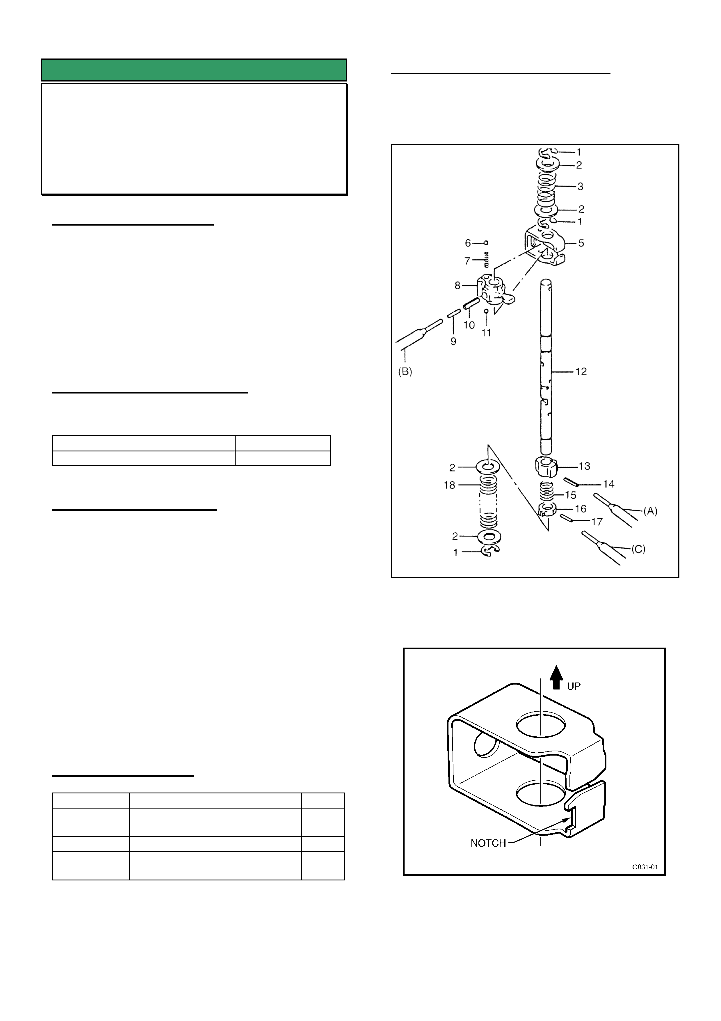
IMPORTANT. During the repair, the gear shift
interlock plate must be installed the right way up as
shown in Figure 2.
PARTS INFORMATION
Part No.: Description: Qty
92124061 Hub Asm. low speed
synchroniser
1
92124055 Gear Counter shaft 2nd 1
92124065 Ring synchroniser, 2nd/3rd
counter gear
1
WARRANTY CLAIM INFORMATION
Use Labour Times information in Warranty
Information section of current PV SIP CD
Figure 1. Drawing from LCRV SIP showing location
of interlock plate (5) in gearshift assembly.
Figure 2. Shows Correct Orientation Of Gearshift
Interlock Plate.

HOLDEN SERVICE TECHLINE________________________________________________________________ JUNE, 2003
7
SERVICE FIX
Front Hub Noises When Turning
YG Cruze
(GROUP 3) TL511-0306
PROBLEM DESCRIPTION
A clicking/knocking type noise from the front wheels
when turning.
Investigations have shown the major cause for
noises in this area is wheel bearings which are
outside manufacturing tolerances.
Retailers who have been replacing driveshafts for this
condition are now requested to cease this practice
and replace wheel bearings as described below.
PRODUCTION RECTIFICATION
Revised front wheel bearings have been fitted to
vehicles from:
ISOVIN: Build Date:
JSAGHY81S00111647 23/01/2003
SERVICE RECTIFICATION
On vehicles with above complaint condition, fit new
wheel bearing as listed in Parts Information to both
sides.
DO NOT replace driveshafts for this condition unless
the noise is still evident after fitting new wheel
bearings.
PARTS INFORMATION
Part No.: Description: Qty:
92125536 Bearing front wheel 2
Attention Parts Managers:
Any of the previous bearings p/n 92124547 should be
returned to HSPO for credit via the CRRM system.
WARRANTY CLAIM INFORMATION
Use Labour Times information in Warranty
Information section of current PV SIP CD
INFORMATION
4WD Selection & Diagnosis
RA 4WD
(GROUP 4) TL499-0306
4WD Selection
Concerns have been raised regarding 4WD shifting
to 4L from 2H.
During this shift, the transfer case ratio is changed,
followed by the front drive being engaged. The front
drive splines must align for front drive engagement to
occur. If spline misalignment occurs, the shift will not
occur and the “4L” indicator lamp in the instrument
cluster will flash more rapidly, indicating an
incomplete shift.
Understanding this will explain the concerns some
customers may have with “4L” engagement from
“2H”.
If the front drive splines do not align exactly and the
warning lamp flashes more rapidly - move the vehicle
slightly to align the front drive splines exactly.
IE.: in A/T vehicles, Select R or D with light brake
application to move the vehicle, then N;
in M/T vehicles select 2nd, move the vehicle slightly,
then select N.
The members will then engage, the “4L” indicator
lamp will stop flashing, and 4L drive is fully engaged.
Note: Use of the handbrake does not affect the
selection of 4L.
Diagnosis
The following five pages of revised “RA Rodeo –
T150 Transfer Case” diagnosis will be provided in the
next LCV SIP CD issue 4.3.
Copy and use of these pages is recommended until
the LCV SIP CD 4.3 becomes available.
For any 4WD shift concerns refer to these pages for
explanations and diagnosis – which will also be
reproduced in future RA Owner Handbooks.

HOLDEN SERVICE TECHLINE________________________________________________________________ JUNE, 2003
8
RA RODEO – T150 TRANSFER CASE
DIAGNOSIS
Neither the Transfer Case Control System or Shift On The Fly (SOF) System can be accessed with the TECH 2 scan
tool. Incorrect diagnosis can be both time-consuming and expensive. Refer to LCRV SIP – MY2003 RA Rodeo –
Section 7 – Transfer Case Control System for correct the diagnostic procedures and symptom charts.
ROAD TESTING
Before attempting diagnosis, the vehicle should be road-tested to determine if a mechanical/electrical fault actually
exists. Many reports of incorrect transfer case or S.O.F. system operation can be attributed to the driving conditions
at the time of “failure”.
Noting the operation of the 4WD, 4 Low, Neutral indicator lamps and the CHECK 4WD warning lamp will provide
valuable information when testing the performance of the four wheel drive system. Observe the operating sequence
of the indicator/warning lamps when operating the transfer case controls, then use the information below to
determine whether or not further diagnosis is required.
SHIFTING FROM 2H TO 4H
1. 4WD Indicator Lamp: Flash rate increases from 2Hz to 4Hz.
Probable Cause: High vehicle speed or extremely low operating temperatures.
Corrective Action: Reduce speed or stop the vehicle and perform the required shift.
At high road speed the relative speed difference between the internal components of the transfer case is too high
for the shift to occur. The TCCM will make four attempts to shift from 2H to 4H. If the shift is not achieved on the
fourth attempt, the 4WD indicator lamp frequency will increase to 4Hz for 10 seconds and then go out. The
transfer case will then remain in 2H.
Similarly, extremely low operating temperature (high transfer case oil viscosity) will give rise to excessive
component speed difference.
2. 4WD Indicator Lamp: Flash rate of 2Hz continues for more than 11.5 seconds.
Probable Cause: Speed or phase difference between LH front wheel and front axle.
Corrective Action: If moving, accelerate and decelerate the vehicle in a straight line.
If stationary, move the vehicle backwards and forwards a few metres.
If there is difference of speed and/or phase between the LH front wheel and axle, the S.O.F. system cannot
operate correctly.
Until the both the transfer case and S.O.F. actions are completed, the 4WD Indicator Lamp flashes at a frequency
of 2Hz. The indicator continues flashing at a frequency of 2Hz until the S.O.F. internal switch indicates front axle
engagement.
By correcting the difference in relative speeds or axle phase, the S.O.F. action can be completed.
SHIFTING FROM 4H TO 2H
1. 4WD Indicator Lamp: Flash rate of 2Hz continues for more than 11.5 seconds.
Probable Cause: High torque loading on drivetrain components – possible ‘wind-up’ condition.
Corrective Action: If moving, accelerate and decelerate the vehicle in a straight line.
If stationary, move the vehicle backwards and forwards a few metres.
High torque loading of the drivetrain will usually occur if the vehicle is driven in 4WD on hard ground, particularly if
performing turning manoeuvres. The high torque load will prevent the ‘separation’ of the front axle and transfer
case components and the vehicle will remain in 4WD.
Moving the vehicle with the road wheels in the straight ahead position will usually reduce the torque loading
sufficiently to allow the shift from 4H to 2H to complete.
NOTE: In cases of extreme drivetrain ‘wind-up’, it will be necessary to lift the front wheels of the vehicle from the
ground to remove the torque loading. This operation should be performed with extreme caution due to the rapid
wheel movement that occurs when the torque load is released.

HOLDEN SERVICE TECHLINE________________________________________________________________ JUNE, 2003
9
SHIFTING FROM 4H TO 4L
1. 4L Indicator Lamp: Flash rate of 2Hz continues for more than 11.5 seconds.
Probable Cause: Spline phase difference between transfer case components.
Corrective Action: A/T – Select [D] range and then [N] range.
M/T – Select 2nd gear and partially engage the clutch, depress the clutch and
select neutral.
Failure to shift due to spline phase difference may occur if the drivetrain is under load. Selecting [D] or [N] (A/T) or
selecting 2nd gear with a gentle application of the clutch (M/T) will generally allow sufficient component movement
for the transfer case shift to complete.
2. 4L Indicator Lamp: Flash rate of 2Hz for 10 seconds, then remains ‘ON’ continuously (A/T only)
Probable Cause: High torque loading on drivetrain components.
Corrective Action: Apply the footbrake and then Select [N] range.
The transfer case H-L Shift Assembly stand-by mechanism cannot overcome the load applied to the H-L shift
components. This condition will usually occur when a high torque loading has been generated between the
drivetrain and the road surface.
Applying the footbrake and then selecting [N] range will allow the components to dissipate the torque loading.
3. 4L Indicator Lamp:` Flash rate of 4Hz
Probable Cause: High engine speed.
Transmission not in [N] or [P] – (A/T)
Transmission not in Neutral – (M/T)
Corrective Action: Reduce engine speed to below 2000rpm.
Select correct transmission range.
Push the 4L Transfer Shift switch.
The TCCM will not allow the transfer case to shift from 4H to 4L or from 4L to 4H if the engine speed is above
2000rpm, the transmission is not in neutral (M/T & A/T) or ‘Park ‘ (A/T). Any of these conditions will cause the
TCCM to enter “Restricted Operation” mode.
NOTE:
‘Restricted Operation’ Mode
The 4H, neutral and 4L shifting mechanism has no synchronisation components. Consequently, attempting to shift
with a high relative component speed difference may lead to component failure. To avoid this incidence, the TCCM
will restrict transfer case and S.O.F. operation if any or all of the following conditions are detected:
• Vehicle is moving.
• Engine Speed above 2000rpm.
• Transmission not in neutral (M/T & A/T) or ‘Park ‘ (A/T).
The programming of the TCCM logic circuit includes a Wait-Time function. When certain conditions are detected
via the input signals to the TCCM, a delay (wait time) will be encountered before the transfer case or S.O.F. system
will operate in response to a driver command.
• A/T: If the vehicle has been idling in any drive range for up to three minutes, the wait-time will be between one
and five seconds.
• M/T: If the vehicle has been idling, with the transmission in any gear and the clutch disengaged, for up to three
minutes, the wait-time will be between one and five seconds.
Should either of the above conditions be continued for longer than three minutes, the wait-time will increase to a
maximum of three minutes.
Wait-time can be reduced to zero by turning the ignition OFF, then ON or driving the vehicle for 5 metres.

HOLDEN SERVICE TECHLINE________________________________________________________________ JUNE, 2003
10
SHIFTING FROM 4L TO 4H
1. 4L Indicator Lamp: Flash rate of 2Hz continues for more than 11.5 seconds.
Probable Cause: Spline phase difference between transfer case components.
Corrective Action: A/T – Select [D] range and then [N] range.
M/T – Select 2nd gear and partially engage the clutch, depress the clutch and
select neutral.
Failure to shift due to spline phase difference may occur if the drivetrain is under load. Selecting [D] or [N] (A/T) or
selecting 2nd gear with a gentle application of the clutch (M/T) will generally allow sufficient component movement
for the transfer case shift to complete.
2. 4L Indicator Lamp: Flash rate of 2Hz for 10 seconds, then remains ‘ON’ continuously (A/T only)
Probable Cause: High torque loading on drivetrain components.
Corrective Action: Apply the footbrake and then Select [N] range.
The transfer case H-L Shift Assembly stand-by mechanism cannot overcome the load applied to the H-L shift
components. This condition will usually occur when a high torque loading has been generated between the
drivetrain and the road surface.
Applying the footbrake and then selecting [N] range will allow the components to dissipate the torque loading.
3. 4L Indicator Lamp: Flash rate of 4Hz
Probable Cause: High engine speed.
Transmission not in [N] or [P] – (A/T)
Transmission not in Neutral – (M/T)
Corrective Action: Reduce engine speed to below 2000rpm.
Select correct transmission range.
Push the 4H Transfer Shift switch.
The TCCM will not allow the transfer case to shift from 4H to 4L or from 4L to 4H if the engine speed is above
2000rpm, the transmission is not in neutral (M/T & A/T) or ‘Park ‘ (A/T). Any of these conditions will cause the
TCCM to enter “Restricted Operation” mode.
SHIFTING FROM 4L OR 4H TO NEUTRAL
1. Neutral Indicator Lamp: Flash rate of 2Hz continues for more than 11.5 seconds.
Probable Cause: Spline phase difference between transfer case components.
Corrective Action: A/T – Select [D] range and then [N] range.
M/T – Select 2nd gear and partially engage the clutch, depress the
clutch and select neutral.
Failure to shift due to spline phase difference may occur if the drivetrain is under load. Selecting [D] or [N] (A/T) or
selecting 2nd gear with a gentle application of the clutch (M/T) will generally allow sufficient component movement
for the transfer case shift to complete.
2. Neutral Indicator Lamp: Flash rate of 4Hz
Probable Cause: High engine speed.
Transmission not in [N] or [P] – (A/T)
Transmission not in Neutral – (M/T)
Corrective Action: Reduce engine speed to below 2000rpm.
Select correct transmission range.
Push and hold the 2H and 4L Transfer Shift switches for 10 seconds.
The TCCM will not allow the transfer case to shift from 2H, 4H or 4L Neutral if the engine speed is above
2000rpm, the transmission is not in neutral (M/T & A/T) or ‘Park ‘ (A/T). Any of these conditions will cause the
TCCM to enter “Restricted Operation” mode.

HOLDEN SERVICE TECHLINE________________________________________________________________ JUNE, 2003
11
SHIFTING FROM NEUTRAL TO 2H, 4H OR 4L
1. 4L or 4WD Indicator Lamp: Flash rate of 2Hz continues for more than 11.5 seconds.
Probable Cause: Spline phase difference between transfer case components.
Corrective Action: A/T – Select [D] range and then [N] range.
M/T – Select 2nd gear and partially engage the clutch, depress the
clutch and select neutral.
Failure to shift due to spline phase difference may occur if the drivetrain is under load. Selecting [D] or [N] (A/T) or
selecting 2nd gear with a gentle application of the clutch (M/T) will generally allow sufficient component movement
for the transfer case shift to complete.
4WD INDICATOR LAMP FLASHES WHEN IGNITION IS TURNED ON
1. 4WD Indicator Lamp: Flash rate of 2Hz.
Probable Cause: Ignition turned OFF with 4H or 4L selected.
Corrective Action: A/T – Select [D] range and then [N] range.
M/T – Select 2nd gear and partially engage the clutch, depress the
clutch and select neutral.
When the ignition is first turned ON, the TCCM initialises and commands the Shift Actuator motor to the 2WD
position. At the completion of initialisation, the TCCM will the command the Shift Actuator motor to the last
selected position. Failure to shift to that position may be due to spline phase difference if the drivetrain is under
load. Selecting [D] or [N] (A/T) or selecting 2nd gear with a gentle application of the clutch (M/T) will generally allow
sufficient component movement for the transfer case shift to complete.
‘CHECK 4WD’ INDICATOR LAMP ON WHEN IGNITION IS ON
1. ‘CHECK 4WD’ Indicator Lamp: ON when ignition is turned ON
Probable Cause: Failure of Shift Actuator motor or harness
Corrective Action: Conduct the test procedure outlined below, replace failed
components.
1. The initial test is best performed at the TCCM. Refer to the TCCM Pin Out illustration and the chart below for
the test conditions and harness pin location.
2. Should the test fail at Step 1, remove the harness connector with the transfer case in each drive range, and
conduct the test on the respective Limit Switch pin.
3. If the test fails at step 1, but passes at step 2, then a harness/connector fault is the most probable cause of
the CHECK 4WD lamp illuminating.
NOTE:
• The ignition switch must be in the OFF position whenever removing or replacing the TCCM or Limit Switch
harness connectors.
• Under no circumstances should the Transfer Case Actuator harness connector be back-probed. This will
damage the weather-pak seal, leading to possible failure of the system due to contamination of the harness
connector and actuator pins.
TCCM Pin Assignment
HOLDEN SERVICE TECHLINE________________________________________________________________ JUNE, 2003
12
TCCM Pin Shift Actuator Pin 2H 4H N 4L
14 LS1 Closed Open Open Closed
5 LS2 Open Open Closed Closed
16 LS3 Closed Closed Open Open
17 LS4 Open Closed Open Closed
NOTE:
“Closed” indicates continuity between the respective pin and GND pin. (Continuity should also exist between the
“Closed” pins.)
TCCM MEMORY ERASE PROCEDURE
1. Bare both ends of two pieces (about 200mm long) of wire,
2. Ensure the ignition is OFF.
3. Remove the driver seat assembly.
4. Locate the TCCM by opening the cut-out in the floor mat.
5. Keeping the TCCM connected, bridge the terminals from the back of the connector as illustrated.
6. Turn ON the ignition, wait for 2 seconds, and turn OFF the ignition after confirming the relay sound.
7. Remove the two pieces of wire, turn ON the ignition again, and confirm the “Check 4WD” lamp in the meter
panel is OFF.
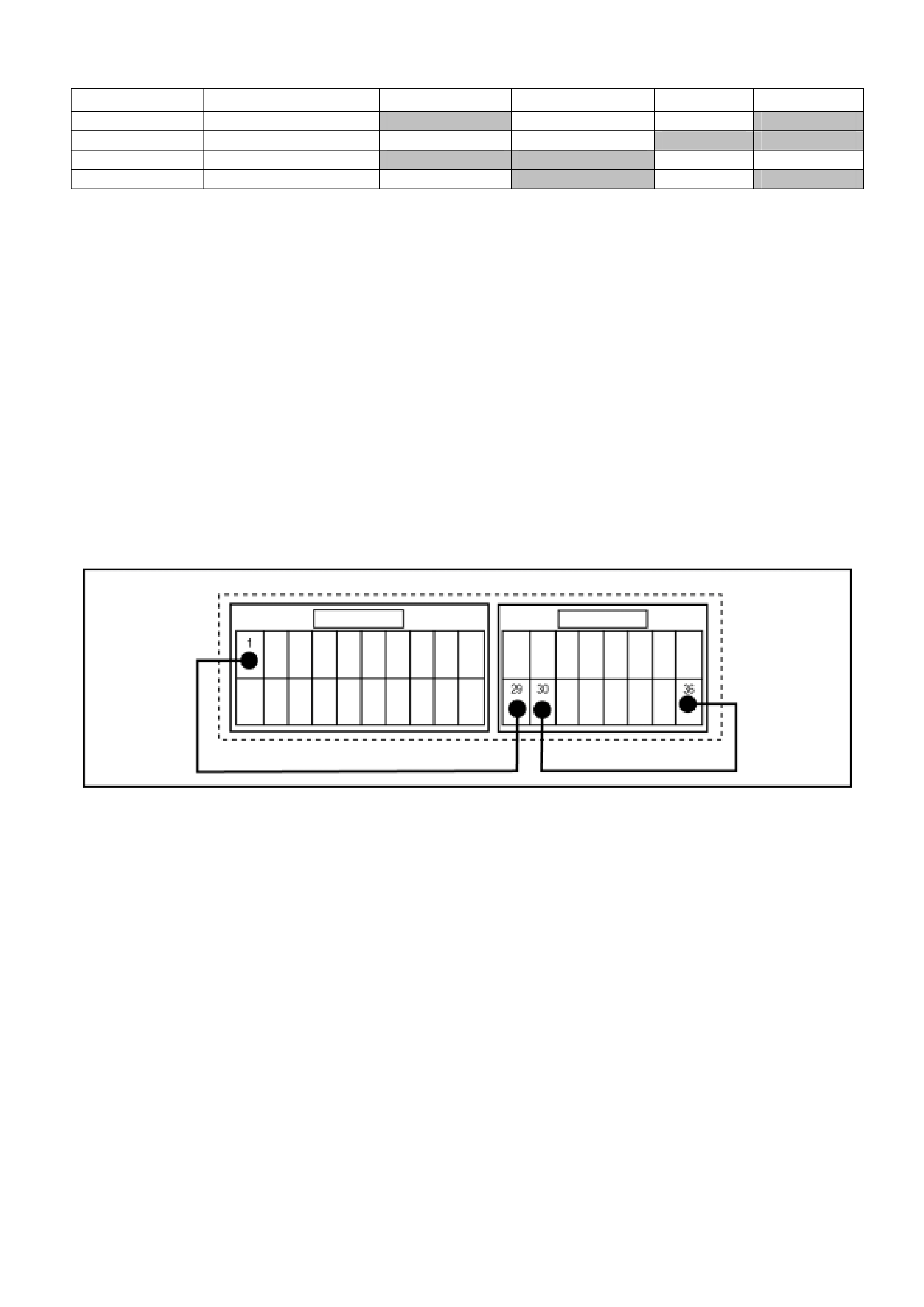
TCCM Memory Clear Pin Assignment

HOLDEN SERVICE TECHLINE___________________________________________________________JULY, 2003
2
DIAGNOSIS HINT
4WD Transfer Controller Memory Erasing
(Resetting) Procedure
RA Rodeo with 4WD
(GROUP 4) TL534-0307
PROBLEM DESCRIPTION
Some Transfer Controller Modules returned to
Holden REPAC have defective material tags with the
following description:
"Check 4WD warning lamp illuminated. Carried out
SIP reset procedure. Unable to reset".
All of these modules have subsequently been reset
using the procedure as detailed in Light Commercial
SIP CD version 4.3 although there was some
difficulty encountered in performing the procedure. It
was found to be difficult to make good contact to pins
29 and 30 on the module which are accessed
through cavity numbers 15 and 16 on the connector.
(The number 15 and 16 pin positions in the connector
do not contain any wiring)
SERVICE RECOMMENDATION
Whenever resetting the Transfer Controller Module
as per SIP procedure, carefully move the wire
probes that are placed in pin positions 15 and 16 to
ensure good electrical contact is made.
In addition, the SIP procedure advises to listen for a
"relay sound". There are in fact two relay sounds; the
first when the ignition is turned on, the second when
the electrical contact necessary for the reset
procedure is made.

HOLDEN SERVICE TECHLINE___________________________________________________________JULY, 2003
3
DIAGNOSIS HINT
Poor A/C Performance In Ambients Above 30 ºC
TF Rodeo Model Year 2002 Petrol and Diesel
(GROUP 2) TL533-0307
The information in this Techline is provided by Air International, supplier of the A/C kits for the above model.
PROBLEM DESCRIPTION
Information received from Holden Retailers has shown that some 2002 Holden Rodeo’s fitted with A/C kit
part numbers 92145593, 92145594 and 92145595 could suffer from “poor A/C performance” in Ambient
temperatures above 30 Degrees.
SERVICE RECTIFICATION
Outlined below is a list of recommended adjustments / procedures / inspections that should help to improve
the A/C system performance on a complaint vehicle:
1. Ensure that the Heater blend door cable is correctly adjusted so that the door is fully closed in the “Max
Cold” position. The following test can be carried out to verify if the Heater blend door is still slightly
opened in the Max Cold position.
! Remove the Glovebox (2 screws)
! Insert the probe of an Electronic Thermometer (approx 100mm) through the hole in the Evaporator
case used for the Thermistor wire.
! Operate the A/C system on Blower Fan speed 2, Recirculation mode, windows closed, Face vent
mode and Max Cold for approx 5 Minutes. Take a reading from your Thermometer, this is the actual
“air off temperature” from the Evaporator coil.
! Remove the Thermometer probe from the Evaporator case and now insert your Thermometer probe
into the Face vent, and take a reading.
! The difference between the “air off” temperature and the Face vent temperature should be no more
than 3 – 5 Degrees C.
! If the Difference is higher the Heater air mix door is still opened – ADJUST and recheck.
2. Check the A/C Drive belt Tension to ensure that no “slippage’ is occurring, the average tension
specification is 50 KG, measured at the longest section of the belt between pulleys. Adjust as required.
3. Remove the Glovebox (2 x screws) Check and Adjust if necessary the Fresh / Recirculation door
activating cable.
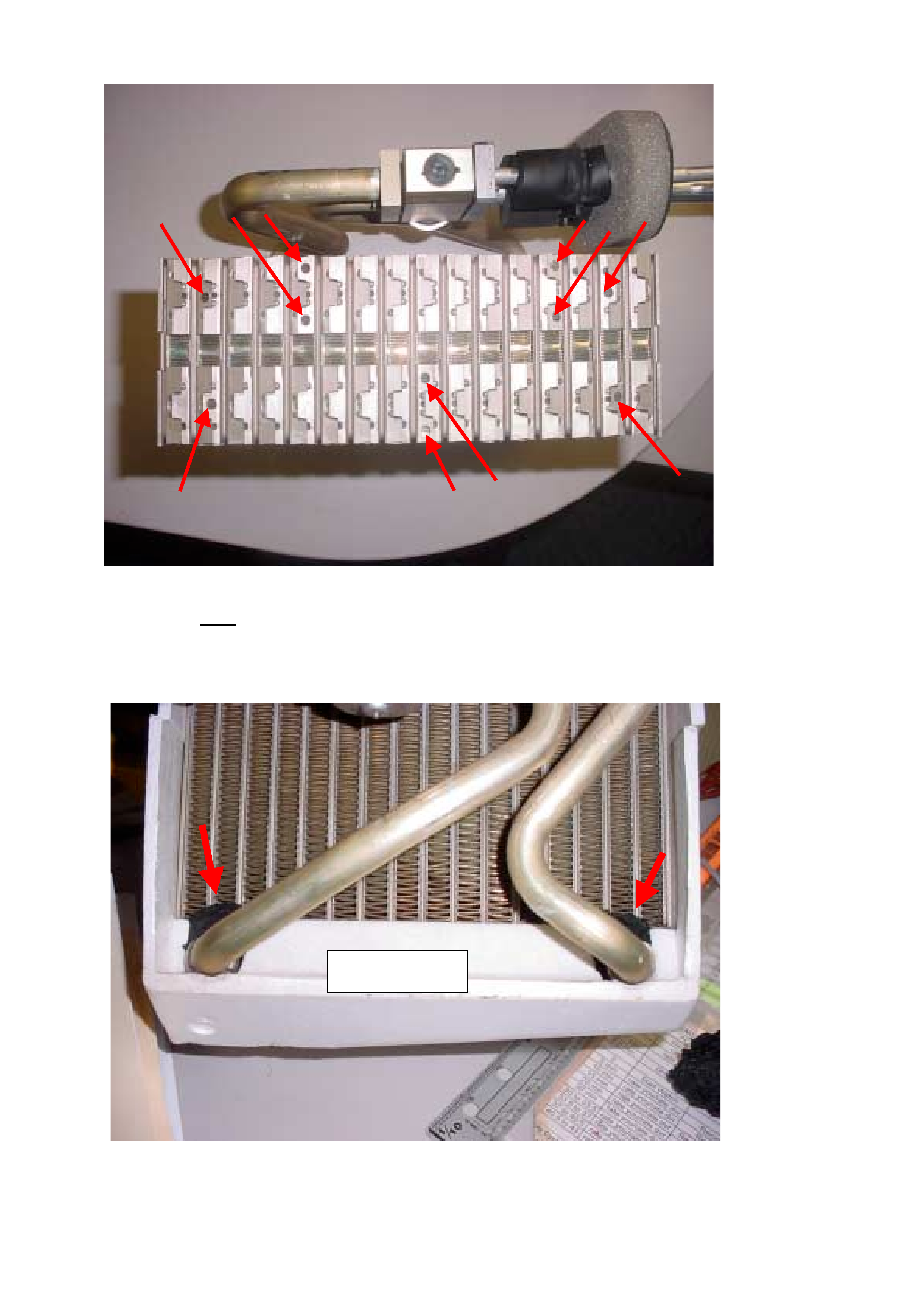
4. Recover the A/C system Refrigerant. Remove the Evaporator assembly (3 nuts). Dismantle the
Evaporator assembly. Carefully remove the Evaporator coil. Referring to Figure A, inspect the
underside of the Evaporator coil to see if the “holes” (paths) outlined on the diagram are in the same
position as the removed Evaporator coil. If your Evaporator has the “holes” in the same location as
Figure A the Evaporator coil is OKAY. Proceed to Step 5. If NOT, replace the Evaporator coil as the
Refrigerant flow paths are incorrect and will affect A/C performance. Refer to Dec 2002 Techline on
“Poor Performance” for details of replacement evaporator.
5. From the Inlet air-side of the Evaporator coil, add “black A/C lagging tape” around the fin area where
the inlet / outlet tubes join the Evaporator tank. See Figure B for the area to be sealed. The reason for
doing this task is to eliminate any possibility of warm / hot inlet air bypassing the Evaporator coil and
mixing with the refrigerated cold air which will then effect the Face vent temperature.
6. If all of the above has been checked and adjusted finally replace the TX valve with part number VS
20558.
7. If all of the above fails to improve the A/C performance to a satisfactory level, contact Air International
Service Department on 1800 673 716.
HOLDEN SERVICE TECHLINE___________________________________________________________JULY, 2003
4
Figure A. Underside Of Evaporator Coil.
Note: Block valve and TX valve Evaporators (Tripac -Gold coloured) must have
the same “hole” positions as shown by arrows.
Figure B. Add black bitumen tape to plug gaps where shown. Apply tape with evaporator coil
in place. DO NOT dismantle.
AIR “ON” SIDE

HOLDEN SERVICE TECHLINE___________________________________________________________JULY, 2003
5
INFORMATION
5000km Service Coupon Error
RA Rodeo
(GROUP OB) TL532-
0307
PROBLEM DESCRIPTION
The first RA Rodeos delivered had yellow
coloured owners handbooks The 5000km
Service Coupons in these books incorrectly
stated that the Manual Transmission and Front
and Rear Differential oil should be changed.
This was corrected in the next reprint of the
owners handbook which was green in colour.
NOTE 1. The first standard oil change for the
M/T and Differentials is at 40,000km or 2 years.
NOTE 2. Owner Handbooks should not be
replaced for this concern.
OWNER HANDBOOK INFORMATION
Part No.: Description: Qty:
92157473 RA Owners Handbook –
yellow printed Nov 2002
1
92162965 RA Owners Handbook –
green printed Feb 2003
1
SERVICE PROCEDURE
Clock Spring Coil Damaged When
Replacing Power Steering Rack
YG Cruze
(GROUP 9) TL526-0307
PROBLEM DESCRIPTION
Investigation of broken clock spring coils
returned to REPAC shows that in every case,
the clockspring damage occurred at the same
time as the steering rack was replaced.
This highlights that technicians are removing the
Rack and Pinion Assembly without observing the
CAUTION notice in the LCV SIP CD Service
Instructions.
The caution notice reads as follows.
CAUTION: Be sure to set front wheels in
straight direction and remove ignition key
from ignition before these steps, otherwise
contact coil of airbag system may be
damaged.
The above caution notice in Light Commercial
SIP CD is found as follows.
Refer Section 3B Manual Rack and Pinion / 3.3
Manual Rack & Pinion Assembly (Steering Gear
Case) - Removal
HOLDEN SERVICE TECHLINE______________________________________________________________NOVEMBER, 2003
6
SERVICE FIX
Intermittent No Crank or No Start
RA
(GROUP 12) TL0541-0311
PROBLEM DESCRIPTION
Customers may advise that intermittently their vehicle
will not crank or will crank and not start.
This problem has been isolated to an intolerance
within the immobiliser control unit software, which can
be highlighted by electrical noise generated from the
accessory socket relay and any accessories powered
from the accessory socket circuit.
PRODUCTION RECTIFICATION
There will be two stages of rectification for this
problem. The first is a revised accessory socket relay
which will be fitted to every vehicle at Port of Entry
starting in early December 2003.
The second will be a revision of the immobiliser
software, which is scheduled for introduction into
production in February 2004.
SERVICE RECTIFICATION
The revised accessory socket relay is now available
from HSPO and should be fitted to any vehicle when
the customer advises of this problem.
Fit the revised relay as per the following steps,
Step 1. Due to the increase in length of the revised
accessory socket relay, fitment may
necessitate the removal of the Instrument
Panel Drivers Side Lower Cover Assembly.
For this procedure refer to:-
LCRV / Service Information / RA Rodeo / Body
/ Section 2C – Cab & Interior Trim / Instrument
Panel.
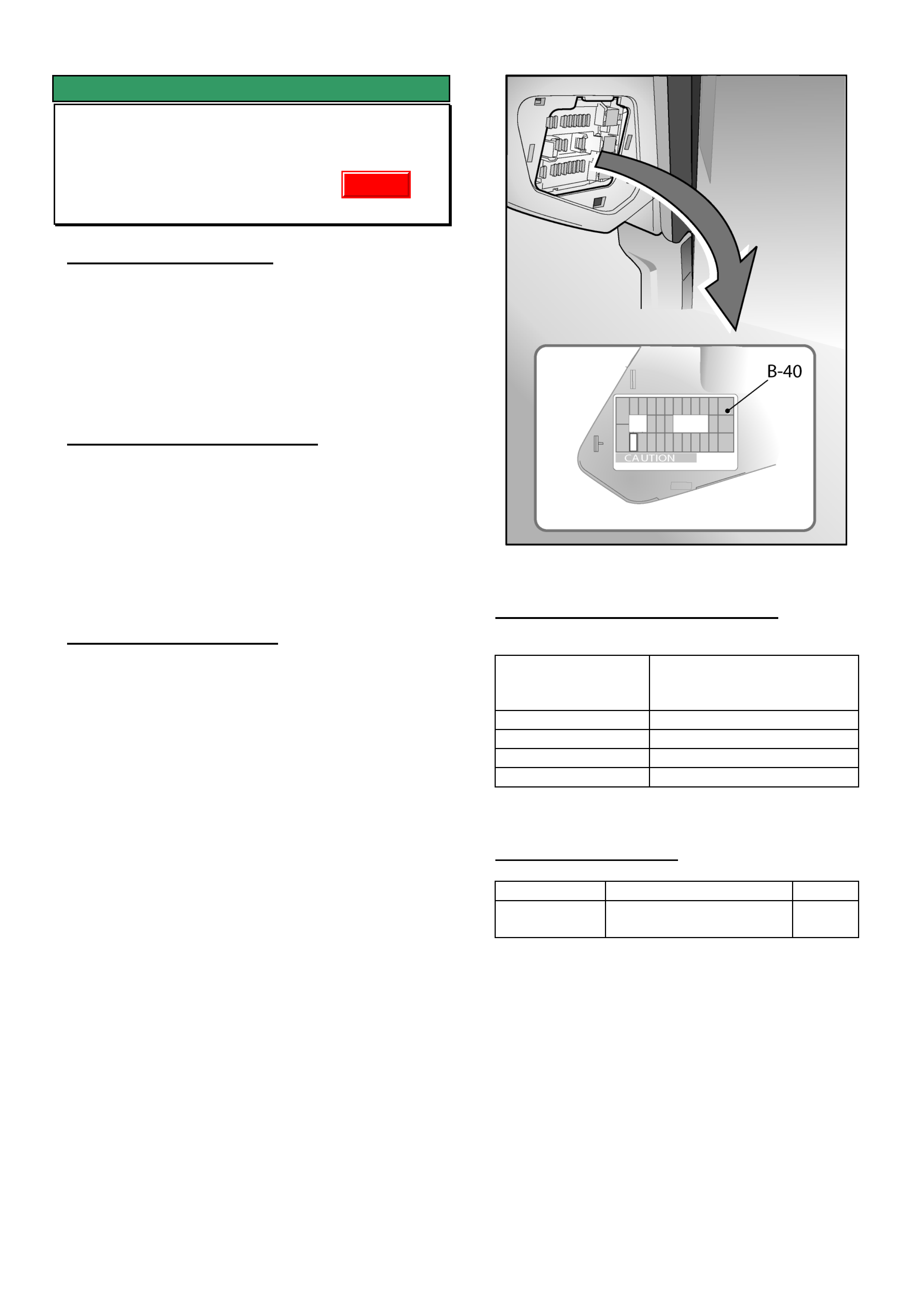
Step 2. Replace the accessory socket relay B-40 with
the revised relay supplied. B-40 is located in
the fuse box at the right hand end of the
instrument panel as per diagram below.
Step 3. If removed, replace the Instrument Panel
Drivers Lower Cover Assembly following LCRV
SIP procedure.
WARRANTY CLAIM INFORMATION
Description Hard Start Service Fix
Accessory Relay
Replacement
Labour Op. No. N000435
Time 0.3 hr
Failure Code 84 Hard Starting
Failure Code NOW N0084 Hard Starting
PARTS INFORMATION
Part No.: Description: Qty:
92147876 Service Fix Accessory
Socket Relay
1
Update
HOLDEN SERVICE TECHLINE______________________________________________________________NOVEMBER, 2003
11
INFORMATION
Built Date Explained
All Imported Vehicles – XC, TS, TT, JS,
ZC, UES, UBS, RA, YG
(GROUP OB) TL0606-0311
Holden Breakpoint Information in Service Techlines,
SMA handout material, Partfinder, etc. usually refers
to a BUILT DATE.
The BUILT DATE is the date the vehicle was
assembled in the factory.
Whenever quoting vehicle details in PIRs, talking to
TAS, etc., always quote the vehicle BUILT DATE.
The BUILT DATE is located in various locations on
imported vehicles.
On TS it is shown on a small label on the radiator
panel. On ZC it is shown on a small label on the strut
tower.
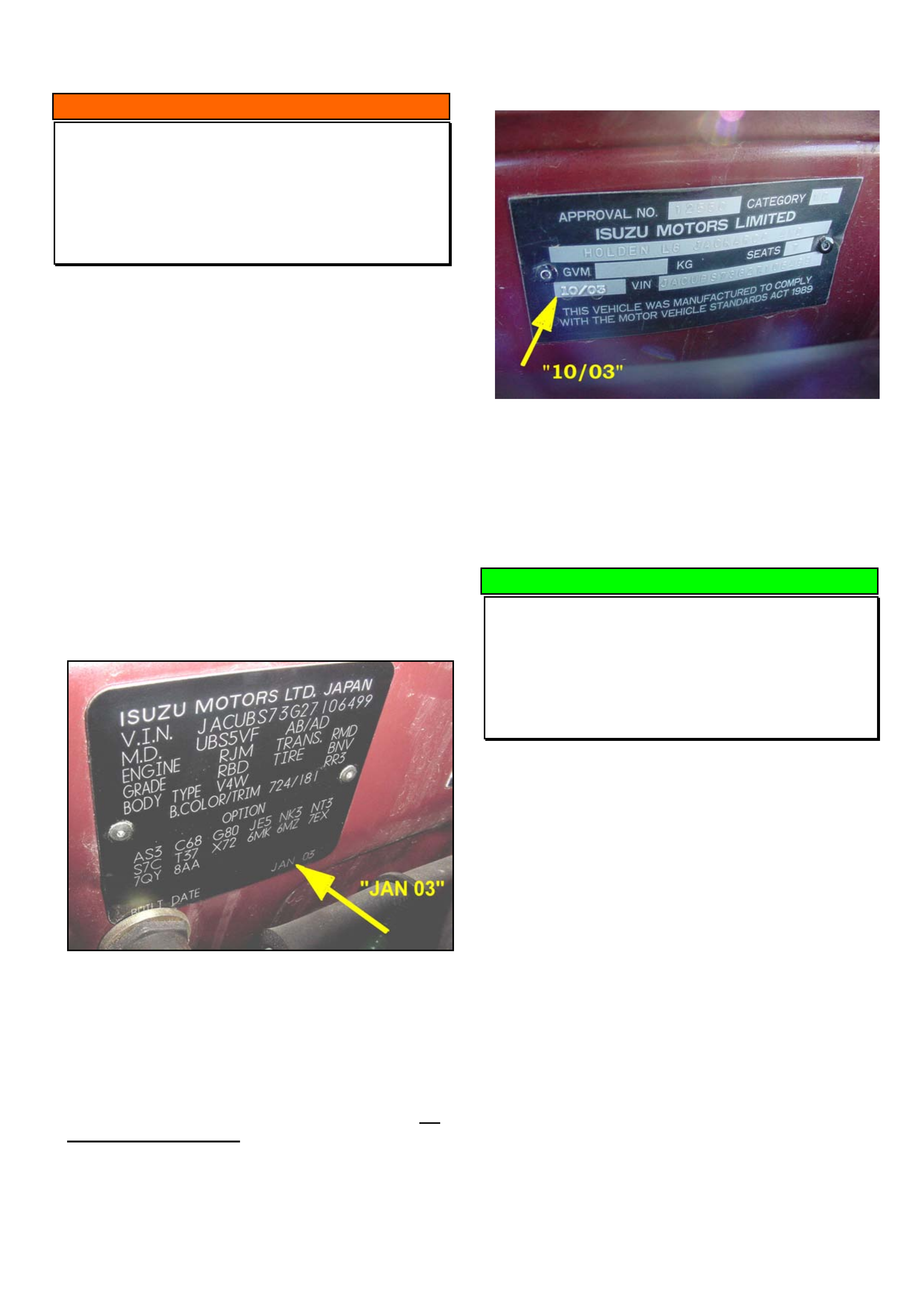
On UBS Jackaroo the BUILT DATE is shown on the
Body/Option plate on the dash panel as shown in
Figure 1.
Figure 1. Body/Option plate - Jackaroo
IMPORTANT. The BUILT DATE described above
must not be confused with the date stamped on the
Safety Compliance Plate rivetted to the dash panel.
Refer Figure 2.
The date shown on the Safety Compliance Plate, for
imported vehicles only, is the date when the plate
was attached to the vehicle at the Port Of Entry (POE)
into Australia. This date can be from 2 to several
months after the vehicle BUILT DATE because of the
time taken for shipping the vehicle to Australia plus
storage at POE.
Figure 2. Safety & Compliance plate - Jackaroo
SERVICE HINT
Transferring Information from Old to New
Modules
All
(GROUP 12) TL0589-0311
When installing a new module the following
information is generally required for inputting into the
new module.
• Vehicle options
• Vehicle configuration
• Code Index
Prior to removing any module, it is recommended to:
1. Connect Tech 2.
2. Record on paper the Vehicle options, Vehicle
configuration, and Code Index.
3. Confirm all the values recorded in step 2 using
TIS 2000 or SIP.
4. Once these values are confirmed they can then
be entered into the new module when called for
by Tech 2 during the installation process.
HOLDEN SERVICE TECHLINE______________________________________________________________NOVEMBER, 2003
13
ACCESSORY INFORMATION
A/C Compressor Clutch Wire Damaged
During Installation
RA Rodeo & 4JH1 Diesel Engine
(GROUP 2) TL0586-0311
PROBLEM DESCRIPTION
It has been found that during installation of the air
conditioning compressor p/n 61366371 for the 4JH1
engine, it is possible to trap the lead wire for the
clutch between the compressor and the mounting
bracket. When the fasteners are tensioned, the wire is
damaged, causing either an open circuit, or short
circuit to ground. This may cause a failure of electrical
components within the compressor (which are not
serviceable), requiring the replacement of the entire
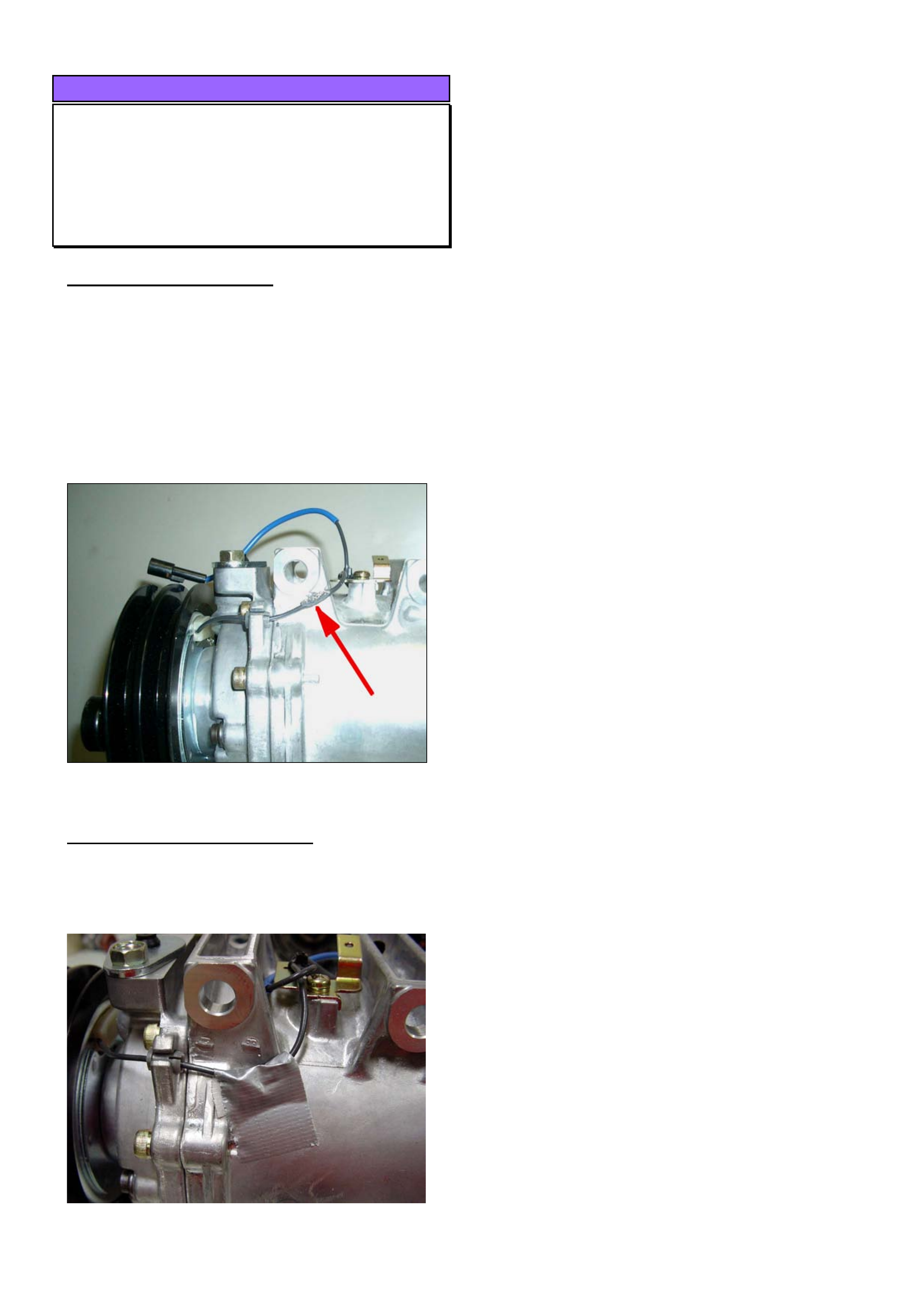
compressor. Figure 1 shows damaged wiring
Figure 1. Shows damaged wire
SERVICE RECOMMENDATION
Prior to installing the compressor, tape the lead wire
against the body of the compressor to ensure it
cannot be trapped when the fasteners are tensioned.
Figure 2 shows recommended taping of wiring.
Figure 2. Shows taping of wire prior to installation
HOLDEN SERVICE TECHLINE______________________________________________________________NOVEMBER, 2003
14
ACCESSORY INFORMATION
HVAC Temperature Control Not Working
– Air Mix Cable Incorrectly Installed
RA
(GROUP 2) TL0587-0311
PROBLEM DESCRIPTION
There have been reports of the HVAC temperature
control (air mix dial) not working.
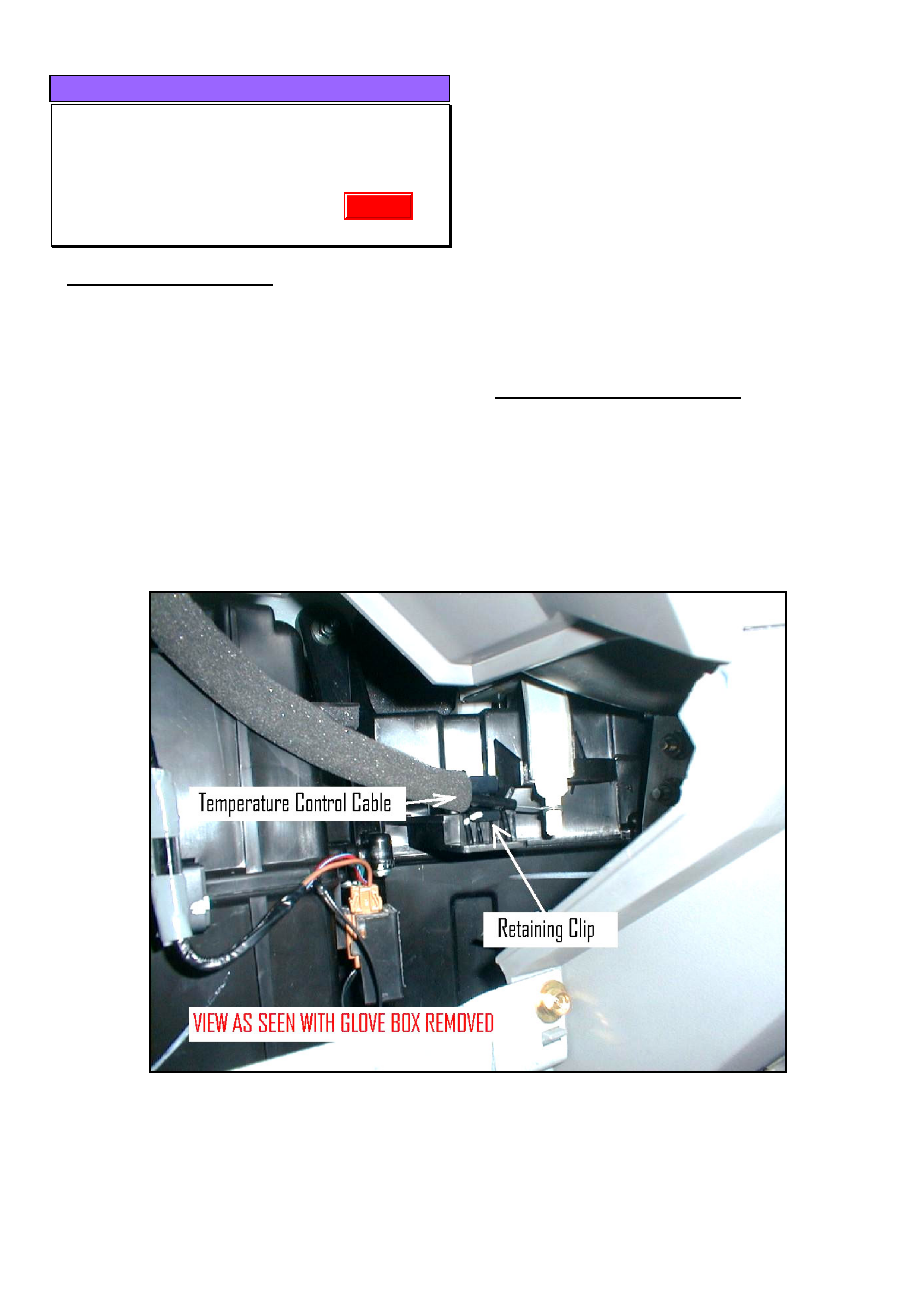
Investigation of complaint vehicles shows this
problem is due to the air mix cable not being held in
the retaining clip. This results in the outer cable
moving, which in turn causes the inner cable to
dislodge from the air mix door control lever.
In most cases, the cause of the above problem is the
cables have not been placed correctly into the
retaining clips when air conditioning has been
originally fitted to the vehicle.
SERVICE RECOMMENDATION
When installing air conditioning (or re-installing the
cable for any reason) it is important to pay special
attention to the correct installation of the air mix cable.
After installing the cable in the retaining clip, ensure
the full range of hot/cold adjustment can be achieved
with the control dial.
Figure 1. Shows Temperature control cable correctly retained in clip on side of HVAC case.
Update
HOLDEN SERVICE TECHLINE______________________________________________________________NOVEMBER, 2003
15
ACCESSORY INFORMATION
Check Engine Light Comes On After
Fitting Cruise Control
RA (LT with 4JH1 Engine Only)
(GROUP 12) TL0601-0311
The following information must be read in conjunction
with the Cruise Control Fitting instructions.
PROBLEM DESCRIPTION
After fitting cruise control, the check engine light
comes on and DTC P0703 (brake switch incorrect
signal) is logged.
The RA Rodeo (LT, 4JH1 diesel) brake switch has 4
contacts. A recent change in vehicle self diagnostics
now requires all four brake switch contacts to be
checked. Consequently, after fitting cruise control,
DTC P0703 will be logged as existing cruise control
patch harnesses do not make contact with all of the
terminals in the brake switch.
REMEDY
On vehicles where the CEL comes on after fitting
cruise control, perform the following rework. This
rework should also be performed on any accessory
cruise control kit made prior to batch code “0025303”.
1. Disconnect the cruise control brake patch
harness.
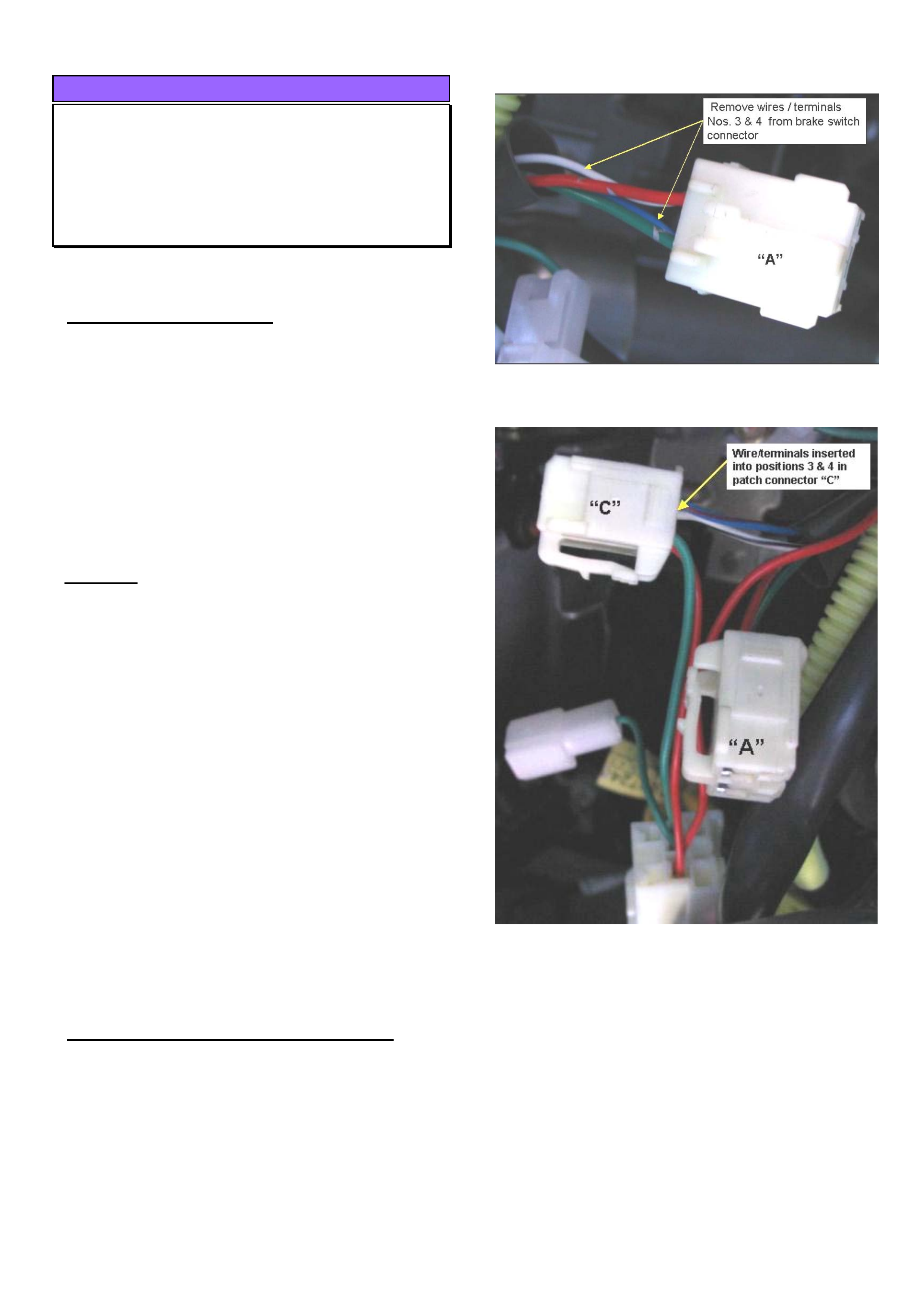
2. Remove the anti back-out combs from both the
vehicle brake switch connector “A” and the cruise
control patch harness female connector “C”.
3. Release the retaining tangs and back out the
terminals 3 & 4 from the brake switch connector
“A”. Refer Figure 1.
4. Now insert these into terminal positions 3 & 4 in
the cruise control connector “C” as shown in
Figure 2.
5. Replace the anti-back out combs and re-connect
the patch harness to the vehicle.
CRUISE CONTROL KIT RECTIFICATION
Cruise control kits P/N 92145334 made from batch
code 0025303 onwards have had their patch
harnesses revised to overcome the above condition.
NOTE: The batch code which is located on the label
on the box refers to the day of the year the kit was
produced. In this case 0025303 refers to the 253rd
day of the year 2003.
Figure 1. Brake Switch Connector A
Figure 2
HOLDEN SERVICE TECHLINE______________________________________________________________NOVEMBER, 2003
16
ACCESSORY INFORMATION
Cruise Control Does Not Engage When
Activated
RA
(GROUP 12) TL0593-0311
The following information is to read in conjunction with
the Cruise Control Fitting instructions.
PROBLEM DESCRIPTION
When checking operation after fitting cruise control
accessory kit, it is observed the "cruise control" LED
illuminates but the system does not engage.
The cause for this condition may be due to incorrect
wiring on the cruise control harness brake switch
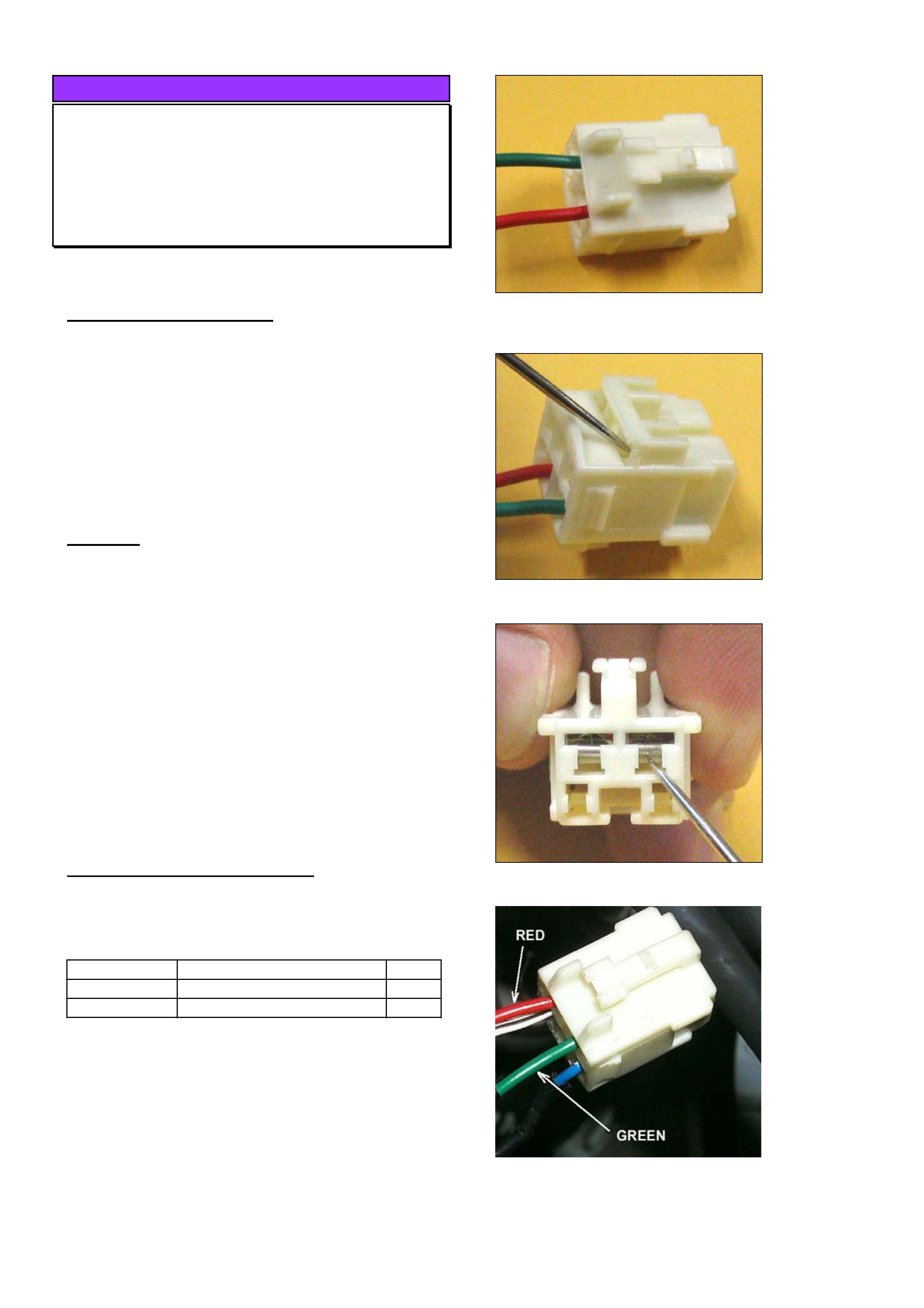
connector. Investigations show the the red and green
wires in the connector have been installed the wrong
way around in some kits manufactured in September
2003. Refer Figure 1.
REMEDY
Check if the cruise control patch harness wires at the
brake switch connector match the colours of the
corresponding wires in the vehicle harness; i.e. Red
to Red, Green to Green. If they don’t match, proceed
to swap the wires around as follows.
1. Remove the anti-backout comb from the cruise
control patch harness. Refer Figure 2.
2. Release the terminals for the Green and Red
wires. Refer Figure 3.
3. Swap the wires over in the connector housing.
The green goes into pin 1 and the red into pin 2
as shown in Figure 4. Refit the anti-backout
comb.
ACCESSORY KITS AFFECTED
The kits affected are those with Batch numbers
between 00025003 and 00025303. The batch
number is stamped on the edge of the part no. label.
Part No.: Description: Qty
92145334 Cruise control kit – 4JH1 1
92145971 Cruise control kit – 6VE1 1
Before installing any kit built between the above batch
numbers check and correct the brake switch
connector wiring as described above.
Figure 1. Shows red and green wires installed wrong way
round in cruise control brake switch connector
Figure 2 Releasing backout comb.
Figure 3 Releasing wire terminals
Figure 4. Shows red and green wires installed correctly
HOLDEN SERVICE TECHLINE______________________________________________________________NOVEMBER, 2003
17
ACCESSORY INFORMATION
Change To Accessory Cruise Control
Fitting Instructions
RA (LT with 4JH1 Engine Only)
(GROUP 12) TL0592-0311
The following information is to be read in conjunction
with the Cruise Control Fitting instructions.
PROBLEM DESCRIPTION
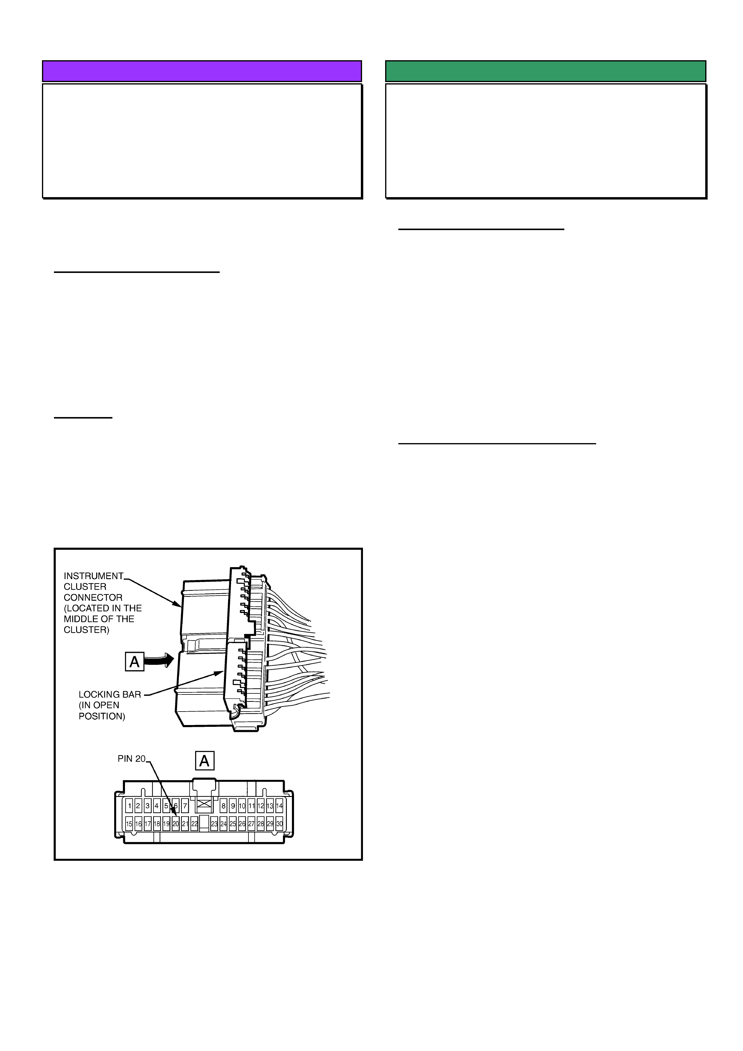
The current fitting instructions for the LT 4JH1 engine
cruise control kit P/N 92145334 indicate that
receptacle 20 in the instrument cluster connector is
vacant, and to place the orange wire/terminal from the
kit into this position. This is no longer correct as
receptacle 20 is now occupied.
REMEDY
As per the current fitting instructions, remove the
terminal retaining clip from the connector. Then
release the terminal in position 20 (Green/Yellow
wire) and tape back against the vehicle harness.
Place the orange wire/terminal from the cruise control
kit into position 20.
NOTE: Fitting Instructions “FD1146 DEC03” have
been modified to reflect above changes.
SERVICE FIX
Air Conditioning Noise Caused By Low
Refrigerant Charge
RA
(GROUP 2) TL0596-0311
PROBLEM DESCRIPTION
Some customers may report a hissing/gurgling noise
coming from the dash area when the A/C is operating.
Investigations show that this noise, which occurs as
refrigerant flows through the TX valve, is louder in
vehicles which have low refrigerant levels.
Low refrigerant level can also cause compressor rattle
(affecting compressor life) therefore, refrigerant level
should be checked before commencing with
compressor noise diagnosis.
SERVICE RECOMMENDATION
For owner complaints of noisy A/C, ensure that the
system has the correct charge of refrigerant. The
only way of ensuring this is to remove the existing
charge and recharge with the specified amounts as
follows:
Refrigerant R134A Diesel 700 ± 25 grams
Petrol 750 ± 25 grams
Retailerships must use A/C charging equipment
capable of accurately measuring out the refrigerant
charge specified. When cans of refrigerant are used
for recharging it is generally not possible to achieve
the same level of accuracy as a proper charging
station. Cans are therefore not recommended for
charging.
The A/C fitting instructions detail the correct
evacuation and charging procedure. Following this
procedure will ensure that the system is correctly
evacuated and that the complete charge is transferred
into the vehicle.
Cooling Performance.
Another essential reason for having the correct
amount of refrigerant in the system is for achieving
best cooling performance. This cannot be achieved
with an undercharged or overcharged system.
Noises from Refrigerant Pipes & Hoses
Refrigerant pipes and hoses can generate noise if
they touch other components. Check all routing and
adjust or isolate all lines from body and engine
components as required.
HOLDEN SERVICE TECHLINE______________________________________________________________NOVEMBER, 2003
18
ACCESSORY INFORMATION
Accessory Pre-Cleaner For Air Cleaner
Element
TF and RA with 4JH1 Diesel
(GROUP 6A) TL0572-0310
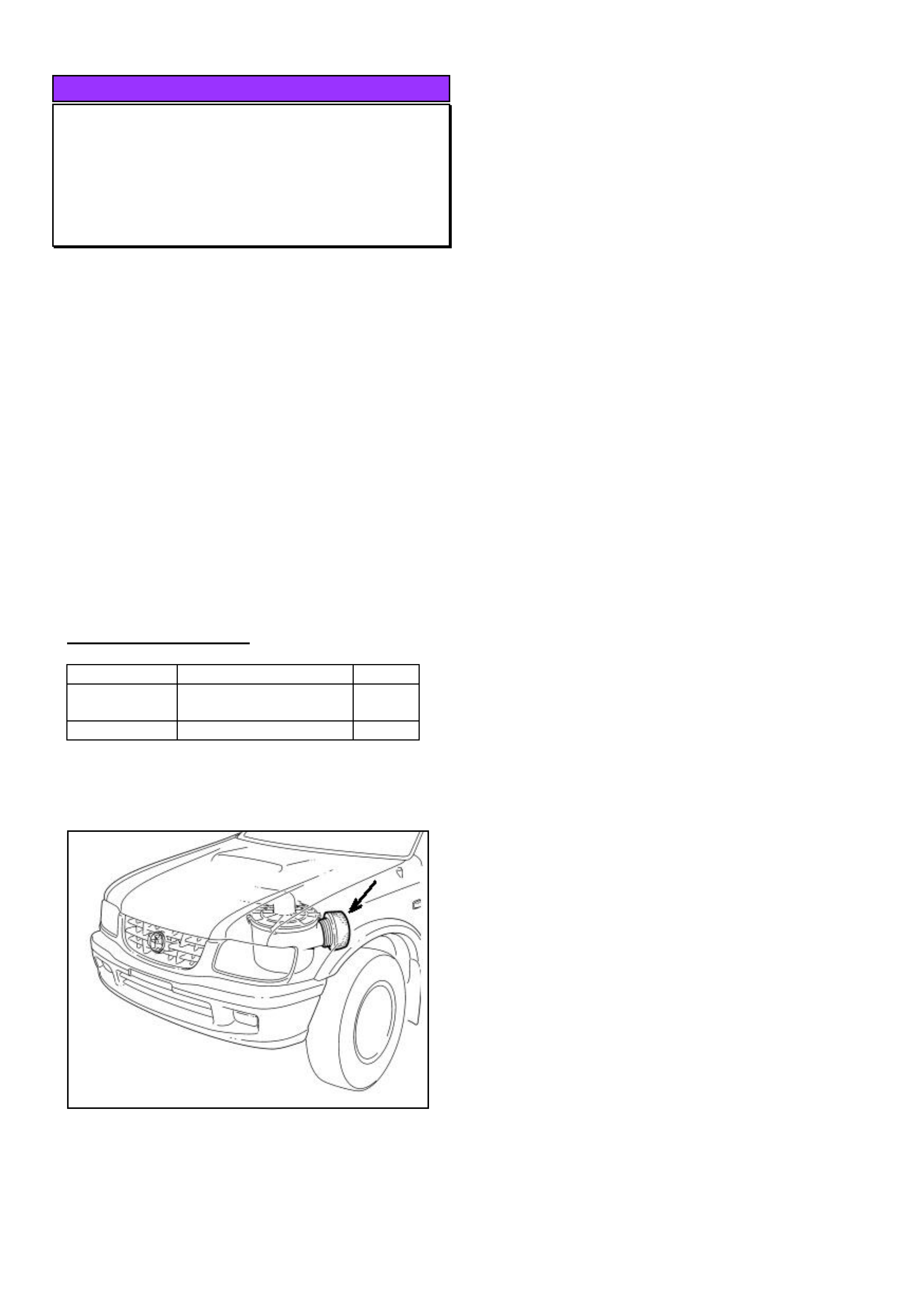
A filter which pre-cleans air prior to it entering the
standard air cleaner element is now available from
HSPO as an accessory fitment.
For vehicles which operate in “extreme”¿ dusty
conditions, this filter is available as an accessory for
prolonging the life of the standard air cleaner element.
¿ ( For a definition of “extreme” conditions refer to the
Servicing section of the Owners Handbook.)
The pre-cleaner is an oil-foam type filter and comes in
a quantity of 2 per package. The package also
contains fitting instructions and an Owner Servicing
Instruction Sheet.
NOTE: The pre-cleaner is to be fitted at customer
expense.
PARTS INFORMATION
Part No.: Description: Qty:
92148001 Air cleaner – prefilter
element.
1
92147879 Filter oil 1
Figure 1. Shows prefilter