
2
20
00
04
4
S
SE
ER
RV
VI
IC
CE
E
T
TE
EC
CH
HL
LI
IN
NE
ES
S
© 2006 GM Holden LTD. A.B.N. 84 006 893 232
Service Department
A “HOLDEN” Product.
BRISBANE SYDNEY MELBOURNE ADELAIDE PERTH
For the latest and/or any missing Techline bulletins,
please refer to Holden Lionheart
HOLDEN SERVICE TECHLINE _____________________________________________________________FEBRUARY, 2004
5
SERVICE FIX
LSD Additive Available For Oil “Top-Up”
VS/VT/VX/VU/WH with IRS LSD
(GROUP 04) Re-Issue TL279A-0401
This Techline supercedes the previous one in Issue 4,
May, 2002. It is revised by correcting the kit contents
and clarifying that usage is only for “top-up”, NOT for
an axle “chatter” fix.
BACKGROUND
Many vehicles have previously had LSD additive and
a revised pinion seal installed for a “chatter” condition
(Refer to Dealer Letter DL 30/02).
The additive is now available separately, for any of
the above vehicles whose differentials require oil
replenishment or top-up following a repair.
This additive is NOT for use in correcting LSD
“chatter” complaints until a chatter kit has
been fitted.
LSD “chatter” complaints must still be corrected in
vehicles covered by warranty by the use of an LSD
“Chatter” Kit – Refer to Dealer Letter DL 30/02 which
advises the method of obtaining LSD Chatter Kits
Free of Charge and the Dana provision of automatic
kit replenishment at Retailers.
PRODUCTION RECTIFICATION
Final drives with the additive and revised seal
included have been fitted to vehicles from:
ISOVIN: Build Date:
6H8VXK69F1L762226 20/08/01
SERVICE RECOMMENDATION
This additive is ONLY for replenishment of oil to final
drive units that:
(a). are fitted to any vehicle built after breakpoint
L762226;
OR
(b). are built before breakpoint L762226 and have
had the additive and the seal installed as per DL
54/01 or RL 30/02. These vehicles are identified by a
metal ID tag fitted to the rear of the differential,
carrying the words “Field Fix”, as shown here:
PARTS INFORMATION
Part No.: Description: Qty:
92145121 Additive Kit 1
This kit consists of: - 1 bottle, 100ml LSD Additive,
IMPORTANT: This additive is NOT suitable
for use in differentials that are not fitted with
the revised seal and additive – as seal
degradation and failure will result.
DIAGNOSIS HINT
Rear Axle Pinion Seal - Oil Leak
Diagnosis
V & W
(GROUP 4) TL0613-0401
PROBLEM DESCRIPTION
Technicians have reported “oil leaks” from the axle
pinion seal on the assumption that the seal is leaking.
Vehicles with such “leaks” have been investigated
and seals returned for checking. No faults could be
found and the oil leakage is only “assembly oil”.
Pinion oil seals are assembled to axles using oil to
assist installation. At times, excessive oil is used, and
after some use and temperature cycling of the axle,
this excessive oil can run out of the pinion nose –
appearing like an oil “leak” from a faulty or damaged
seal.
PRODUCTION RECTIFICATION
Holdens axle supplier will be changing from
installation oil to grease, used in lesser quantity, that
will not migrate out of the pinion seal.
Breakpoint information for this change will be advised
in a future Breakpoint Summary page entry in
Techlines.
SERVICE RECTIFICATION
Summary: Clean off excess oil.
Should any vehicle be presented with an apparent oil
“leak” at low kms or age – do not immediately replace
the seal - wipe off the excess oil and road test for any
continuing immediate leak. If none occurs, monitor the
vehicle at next service.
HOLDEN SERVICE TECHLINE _____________________________________________________________FEBRUARY, 2004
6
SERVICE FIX
Gear Shift Lever Rattle/Buzz - Caused by
Shifter Linkage Rattle
VTII, VX, VU, VY, V2, with Gen III & M/T
(GROUP 7A) REVISED TL608A-0401
This techline replaces the previous one TL608-0311
in issue 11,2003. It is revised by changing the
lubricants to ones that are currently available (shown
in red) and updating Production breakpoint
information.
PROBLEM DESCRIPTION
Complaints may be received of gear shifter “rattle” at
various engine speeds/road speeds. Most common
complaints are from 3rd or 4th gears.
The condition is a “metallic rattle” which can be heard
by removing the gear knob/lever assembly, then
revving the engine in neutral with medium to heavy
throttle, above 2500rpm – as a quick diagnosis. The
shifter linkage rattle occurs mainly during heavy
acceleration in 3rd or 4th gear above 3000rpm. The
rattle is more prominent if you touch the back of the
gear knob with your finger in 3rd gear, or if you touch
the front of the gear knob with your finger in 4th gear.
It is recommended that this test be done with a known
non-rattling gear knob, so no confusion exists.
NOTE: the following procedure must not be carried
out until diagnosis and any necessary repair, as
described in Issue 11, November, 2003 Service
Techline for “Knob Rattle/Buzz” has been carried out.
EG: Where the Gear Lever & Knob Assembly has
been assessed and changed if necessary, and the
source of “gear lever rattle” has been defined as
coming from the shifter mechanism – NOT the lever
and knob assembly.
PRODUCTION RECTIFICATION
Revised shifter assemblies with anti-rattle feature, as
described in this bulletin, introduced in production
from
ISOVIN: Built Date:
6G1YK42F14L213500 08/12/2003
SERVICE RECTIFICATION
Summary: Fit a Shifter Upgrade Kit as described
below.
NOTE: Upgraded “exchange” Shifters have been
supplied via TAS and HSPO since mid 2003 – These
parts do NOT need upgrading as described below,
and must not be upgraded or claimed for as warranty.
These exchange assemblies are identified by the
presence of either four red fibre washers between the
bridging piece and levers, or the black plastic “linked”
washers (6) shown below.
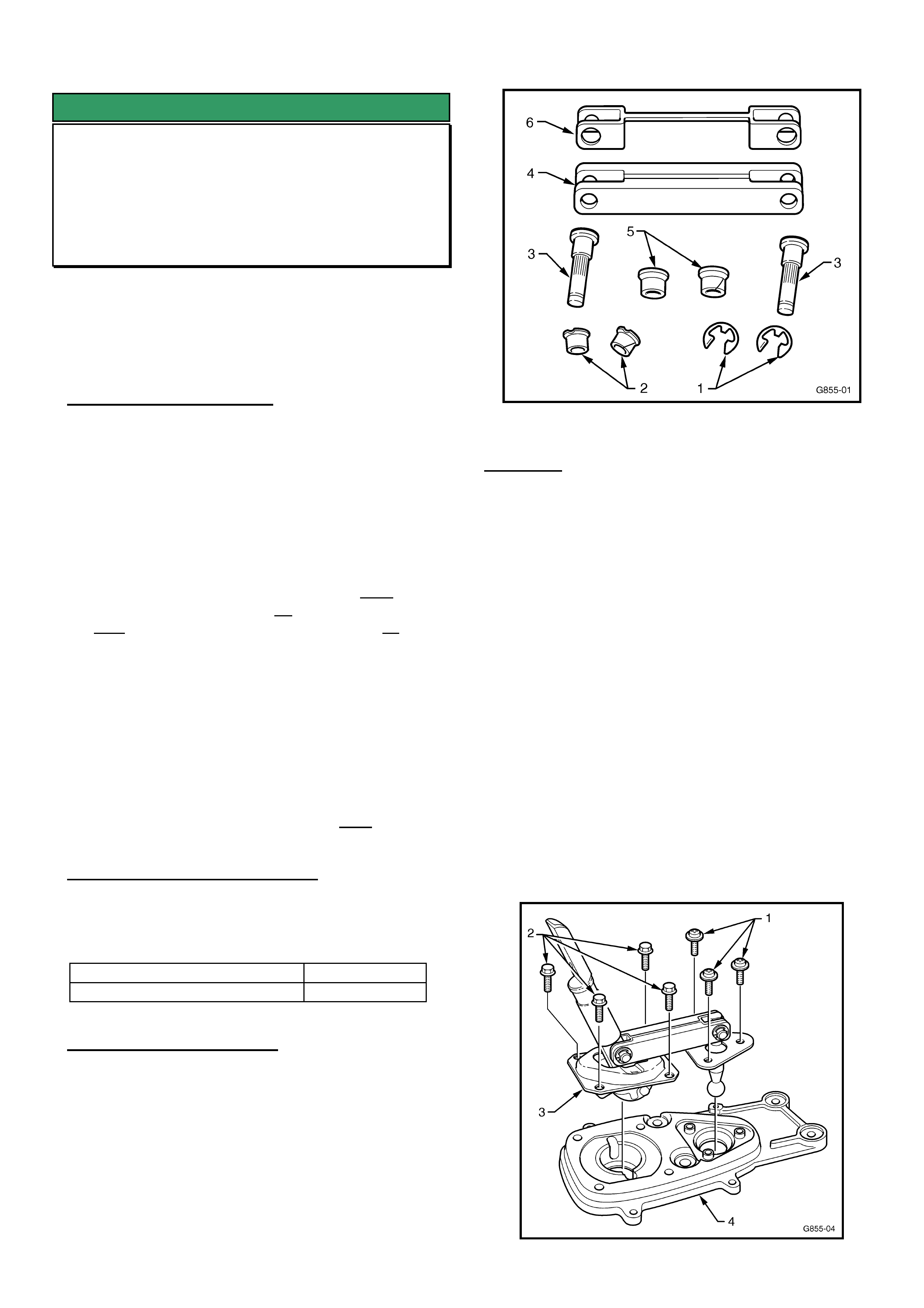
Bridging piece and related retaining parts (latest
types shown).
REMOVAL
1. Disconnect the battery earth lead.
3. Place gear lever in neutral.
4. Remove Gear shift knob/boot/lever assembly, and
centre console including the console cap - as per
the relevant procedures in Passenger SIP
Sections 7B3 and 1A3 for the model vehicle being
rectified.
5. Remove shifter cover and boot assembly by
removing the three Philips head screws.
6. Remove shift lever boot retaining plate:
Early build vehicles – remove the four bolts
securing the shift lever boot retaining plate, from
inside the vehicle, and lift off the plate;
Late build vehicles – remove the four nuts
securing the shift lever boot retaining plate to the
floor pan after raising the vehicle on a hoist. Front
LH nut access is limited, remove using an open
end spanner.
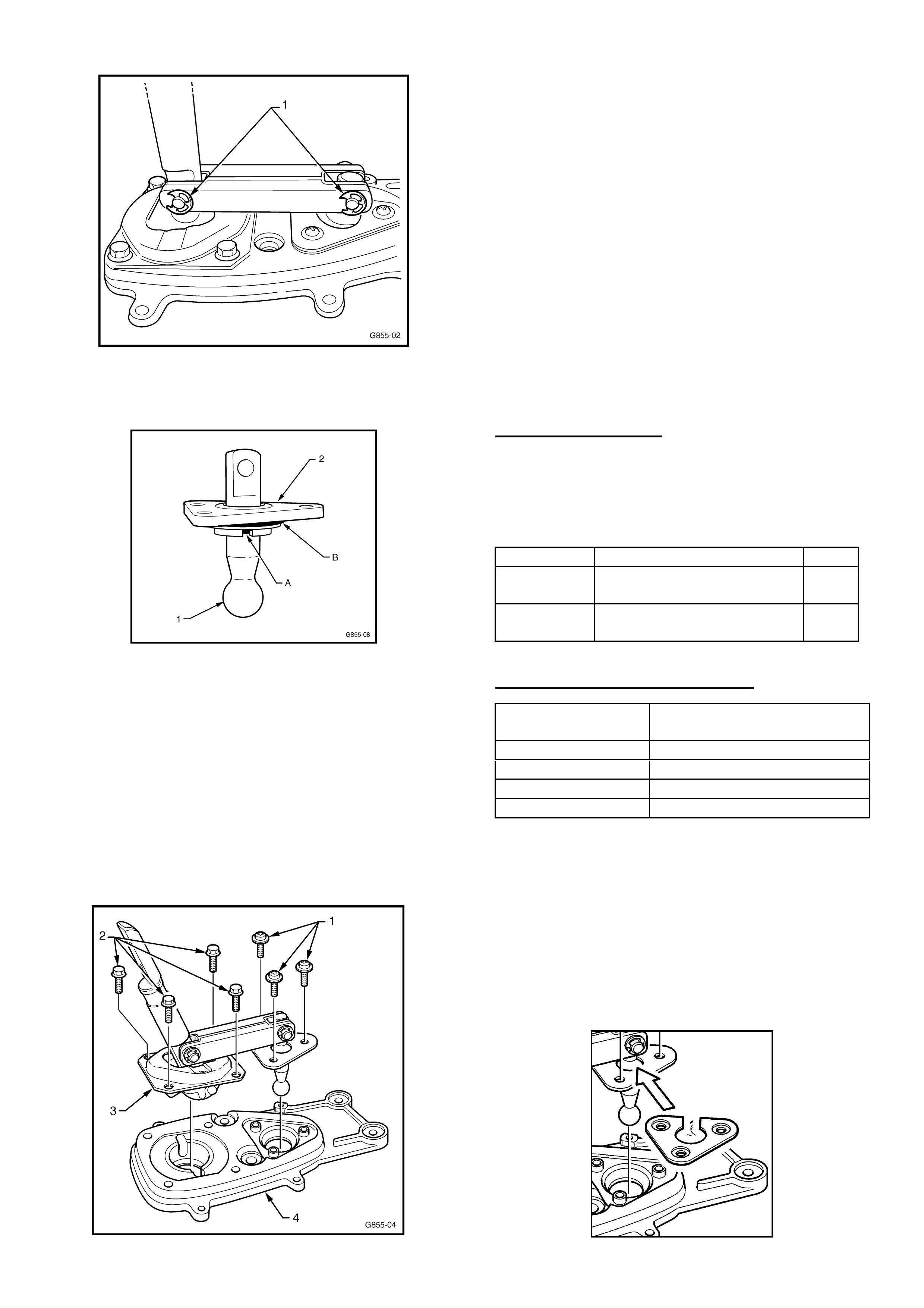
7. Remove the three self tapping screws (1)
retaining the front selector lever pivot assembly,
using a Phillips screwdriver – see Figure 1.
8. Remove the four hex head screws (2) holding the
rear selector lever pivot retaining plate (3), from
the baseplate (4) – see Figure 1.
Figure 1.
HOLDEN SERVICE TECHLINE _____________________________________________________________FEBRUARY, 2004
7
9. Lift the front and rear selector levers and bridging
piece assembly up and out of the shifter base
plate (4) on the transmission, as shown in Figure
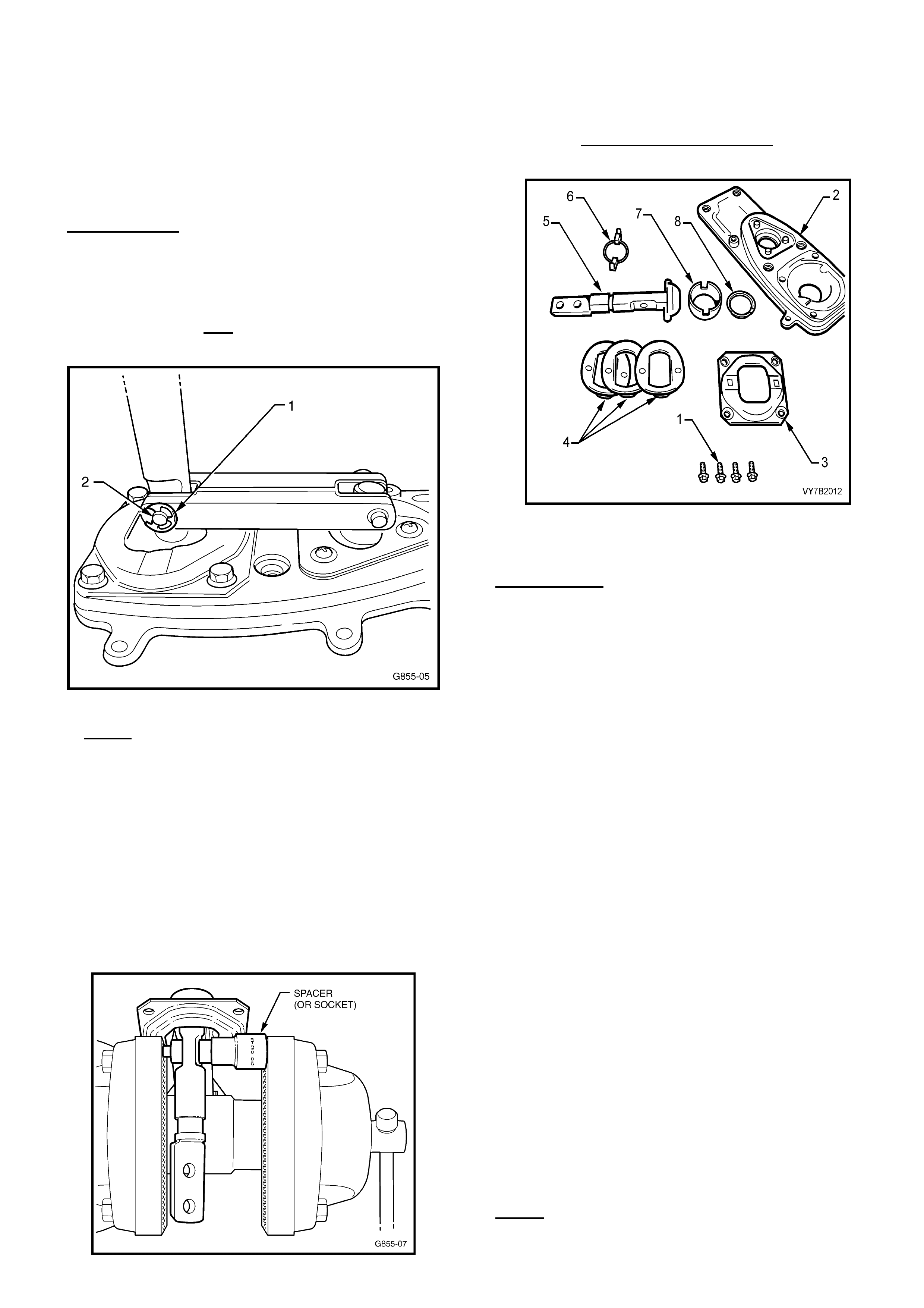
1. Ensure the ball seat (7) and seat support ring
(8) remain in the base plate (2) (these parts
shown in Figure 3).
DISASSEMBLE
CAUTION: During the disassembly process - wear
safety glasses to avoid possible eye injury.
1. Using a small flat bladed screwdriver, remove
circlip (1) from the rear lever/bridging piece retaining
pin (2) – see Figure 2.
Figure 2.
2. NOTE: BEFORE STARTING THIS STEP note
carefully the position and direction of the shifter upper
lever bolt holes and the shaft ‘cutaway’ for
reassembly! This determines the final position of the
gear lever, and gear knob direction! Refer Figure 5.
Tap or press the retaining pin – see Figure 2A - out of
the rear selector lever and bridging piece. This pin is
an interference fit into the selector lever, and may
need to be pressed out of the assembly. This can be
done by clamping the rear lever/pin in a vice, using a
spacer to fit over the pin head (if a suitable spacer is
not available, a suitable sized socket may be used).
Figure 2A. Rear Selector Lever Pin Removal.
3. After pin removal, retain the rear retaining plate (3),
the wave springs (4), and guide (6) shown in Figure 3
for re-use. Note the order of removal of the wave
springs and guide for re-assembly.
Figure 3 – showing rear selector shaft and rear
pivot components.
REASSEMBLE
Reassembly uses parts 1, 3, 4, 6, 7, 8 (in Figure 3)
and the following new parts in the Shifter Upgrade Kit,
• Front Selector Lever
• Front Selector Lever Retainer (triangular plastic)
• Front Selector Lever Retainer O-Rings (2)
• Rear Selector Lever
• Bridging Piece
• Anti-rattle “bridged” washers (black plastic)
• Pins
• small Bushes (blue plastic)
• Large Bushes (blue plastic)
• Circlips
CAUTION: During the reassembly process - wear
safety glasses to avoid possible eye injury.
1. Place the guide (6), wave springs (4) and rear
retaining plate (3) onto the new rear selector lever
(5) - shown in Figure 3 - in reverse order to their
removal.
NOTE: Apply NLGI No.2 lithium soap based EP
grease with molybdenum disulphide, such as Shell
Retinax HDX2 grease, BP Energrease LMS-EP 23 or
equivalent, to all moving parts in the rear selector
lever assembly.
2. Apply NLGI No. 3 Lithium based EP grease,
such as Shell Retinax LX 3 grease or equivalent, to
the new retainer (triangular ball socket) of the new
front selector shaft, then assemble by hand, pushing
the front selector lever (1) into the plastic retainer (2)
– see Figure 6.
NOTE: ensure the plastic ball retainer is located with
O-ring section toward the ball end of the lever as
shown in Figure 4 below.
HOLDEN SERVICE TECHLINE _____________________________________________________________FEBRUARY, 2004
8
Figure 4 – front selector lever and pivot.
1. Install the new “linked” anti-rattle washers (2) to the
new bridging piece (1) – refer Figure 5 below.
Ensure correct diameter holes match the holes in
the bridging piece.
Figure 5 – showing anti-rattle ‘linked’ washer
location.
4. Install the new (blue) bushes to the bridging piece
(outer) holes after lubricating with a NLGI No. 3
Lithium based EP grease, such as Shell Retinax LX
3 grease, or equivalent. . Ensure the bushes are in
the correct size holes in the bridging piece/anti-rattle
washers.
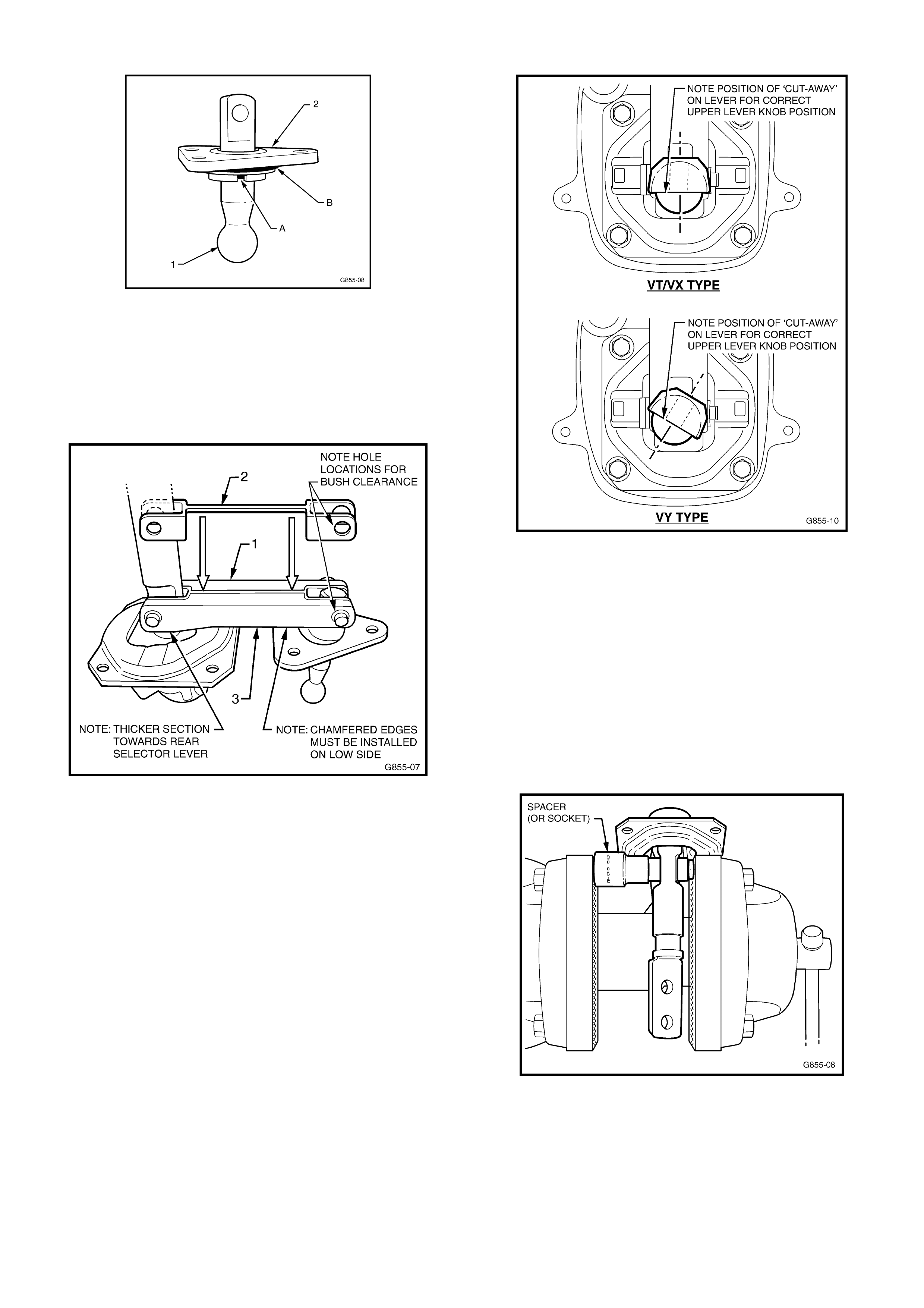
5. Install the new bridging piece assembly (3) to the
two new front and rear selector lever assemblies –
refer Figure 4 above. NOTE: Ensure that the rear
selector lever top retaining screw ‘cut-away’ and
holes are positioned the same way as when
removed from the shifter, and the chamfer on the
bridging piece is to the bottom, as shown in Figure 5
above. Figure 6 shows the correct location of rear
selector lever for both types of shifter:
Figure 6. Shows correct ‘cut-away’ and hole
locations.
6. Install new pivot pins to bridging piece/selector
levers and press home by clamping in a vice - use a
spacer to fit over the pin circlip grooved pin end and
blue bush (if a suitable spacer is not available, a
suitable sized socket may be used). Refer Figure 7.
NOTE: the pins fit easily into the bushes and
bridging piece holes, but are an interference fit into
the lever holes – after initial pressure to start the
pins into the lever holes – STOP - inspect the pin
installation for straightness - then complete the
pressing operation.
Figure 7. Selector Lever Pin Installation.
7. When the pin head butts up against the blue bush,
stop the pressing operation so that the bushes and
bridged washers are not damaged, then fit new
circlips (1) to secure each pin – refer Figure 8.
HOLDEN SERVICE TECHLINE _____________________________________________________________FEBRUARY, 2004
9
Figure 8. – Circlips in final installed position.
8. Install new O-ring seals ‘A’ & ‘B’ to front selector
lever ball socket (2) – see Figure 9.
Figure 9 – front selector lever and pivot.
9. Reinstall the assembled bridging piece/selector
levers (3) into the base plate (4) on the
transmission and reinstall the four rear retaining
plate bolts (2) – see Figure 9 - tightening to the
correct torque specification: 10 –12 Nm.
10. Reinstall the front selector pivot assembly retaining
screws (1) to the baseplate (4) on the transmission
– see Figure 10 - tightening to the correct torque
specification: 5-8 Nm. Note: If a triangular metal
reinforcing plate was fitted to the shifter – refer to
Additional Information at the end of this Techline.
Figure 10.
11. Reinstall dust cover and boot assembly (4 screws)
to the remote shifter assembly on the
transmission.
12 Reinstall the gearshift remote lever boot and plate
and secure to the floor pan as follows:
Early build vehicles – install the four bolts, from
inside the vehicle, tightening to the correct torque
specification: 6-14 Nm.
Later build vehicles - install the four nuts, with
vehicle raised on a hoist, tightening to the correct
torque specification: 15 Nm.
13 Reinstall the gear shift knob/boot/lever assembly
and console/console cap as per procedures in
Passenger SIP Sections 7B3 and 1A3 for the
relevant model.
14 Reinstall the battery ground lead.
PARTS INFORMATION
Use Figure 6 (above) for identification of the shifter
type fitted to the vehicle. To do this, remove the
console boot to determine the angle of the gear lever
retaining bolts and cut-away. Select the correct part
number kit as follows:
Part No.: Description: Qty
92147248 VT/VX type Shifter
Upgrade Kit
1
92147246 VY type Shifter Upgrade
Kit
1
WARRANTY CLAIM INFORMATION
Description Shifter Asm – Rattle
Upgrade
Labour Op. No K000294
Time 1.0 hr
Failure Code 28 rattle
Failure Code NOW K0028
Additional Information:
If a shifter assembly removed from a vehicle is fitted with
the triangular metal reinforcing plate shown below, the
triangular plate and retaining screws (which are longer
than standard screws) should be refitted to the shifter
assembly before reassembly Step 10 above. This action
is only as a precaution, as the new front lever pivot
(white plastic) is a stronger material than the original
part which makes fitting of triangular reinforcing plates
no longer necessary.
HOLDEN SERVICE TECHLINE _____________________________________________________________FEBRUARY, 2004
10
SERVICE FIX
Intermediate Steering Shaft Knock
JR, JS
(GROUP 9) REVISED TL362A-0209
This Service Techline supersedes the previous techline
on this topic TL362-0209 (Issue 9/2002). It is revised
by adding information on greasing the Intermediate
shaft.
PROBLEM DESCRIPTION
A knocking noise on turns caused by clearances within
the steering intermediate shaft components.
SERVICE RECTIFICATION
Summary: On complaint vehicles, replace the
intermediate steering shaft with a new shaft as per
following procedure. If the vehicle has previously been
fitted with a new shaft and still knocks, simply remove
the shaft and add grease as per following procedure
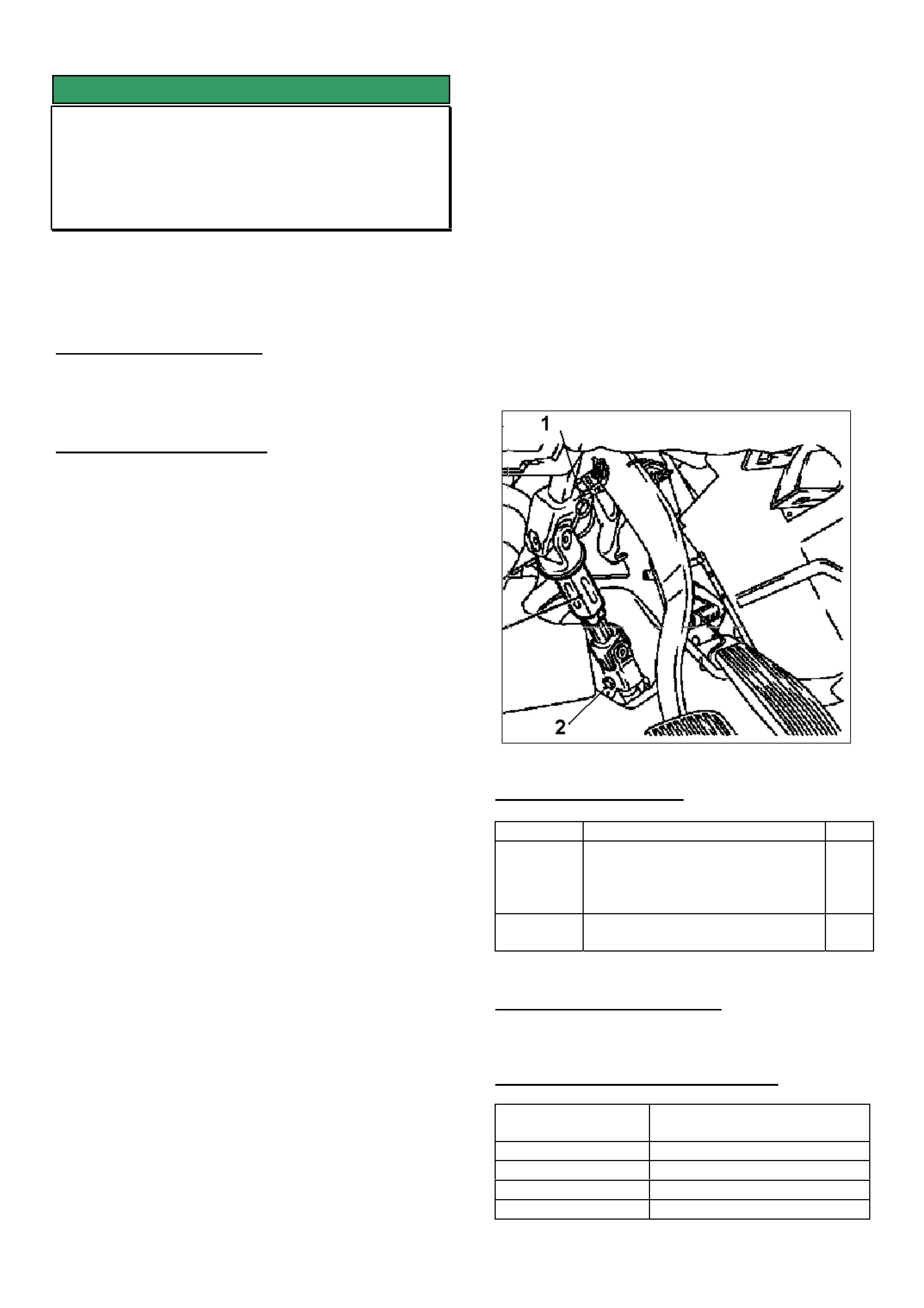
1. IMPORTANT: Disconnect the battery and wait at
least 1 minute for the capacitor in the control unit to
discharge. (Airbag safety precautions as outlined in
service manual Volume 1 must be observed).
2. Centre the steering wheel.
3. Remove foot well panels and air ducting.
4. Loosen the pinch bolts of the steering
intermediate shaft (Nos.1 and 2) and engage the
steering lock, see Figure 1.
5. Compress the steering intermediate shaft and
remove.
6. Unless already installed, fit a new steering
intermediate shaft kit 09119322.
IMPORTANT. Prior to installation, disassemble the
intermediate shaft and grease the sliding area with
grease p/n 90512280. Reassemble the shaft and
slide a few times to spread grease.
7. Release the ignition steering lock, then secure the
shaft using new pinch bolts (Torx screws) and an
appropriate thread locking sealant.
8. Torque the upper and lower pinch bolts to:
22 Nm/16 lbf.ft + 45° + 15°.
Failure to tighten these bolts correctly could result
in not eliminating the knock condition.
9. Refit air ducting and foot well panels.
10. Mark the steering wheel position and remove the
steering wheel using special tool Puller KM 210-A.
11. Offset the steering wheel 2 teeth to the right.
12. If necessary, with a screwdriver, depress the
clock spring locking tab and move the clockspring
until the driving lugs on the steering wheel locate
correctly into the clockspring.
13. Refit the steering wheel and secure the fastening
nut with the locking plate supplied.
Torque to 25 Nm/18 Ibf.ft.
14. Refit the air ducts and foot well panels.
15. Reconnect the battery.
16. Test drive the vehicle and ensure that the steering
is centered.
Figure 1.
PARTS INFORMATION:
Part No. Description Qty.
09119322 Repair Kit - Steering Coupling
Joint (consists of revised shaft,
2 Torx screws, 1 locking
washer)
1
90512280 Grease (High adhesion type)
100 gram
1
SPECIAL TOOL REQUIRED:
KM-210-A Puller
WARRANTY CLAIM INFORMATION
Description Repair Kit - Steering
Coupling Joint - Replace
Labour Op. No. E000302
Time 0.8 hr
Failure Code 28 rattle
Failure Code NOW E0028
HOLDEN SERVICE TECHLINE _____________________________________________________________FEBRUARY, 2004
11
SERVICE FIX
Rear Disc Brake Scraping Noise
VY Regular Cab & Crewman
(GROUP 5) REVISED TL0555B-0401
This Techline supercedes TL0555A-0310 in issue 10,
2003. It is revised by changing Service Rectification
from replacing rear axle asm. to machining the rear
disc brake rotors. This information was also released
in DL 6403 dated 16 Dec 03.
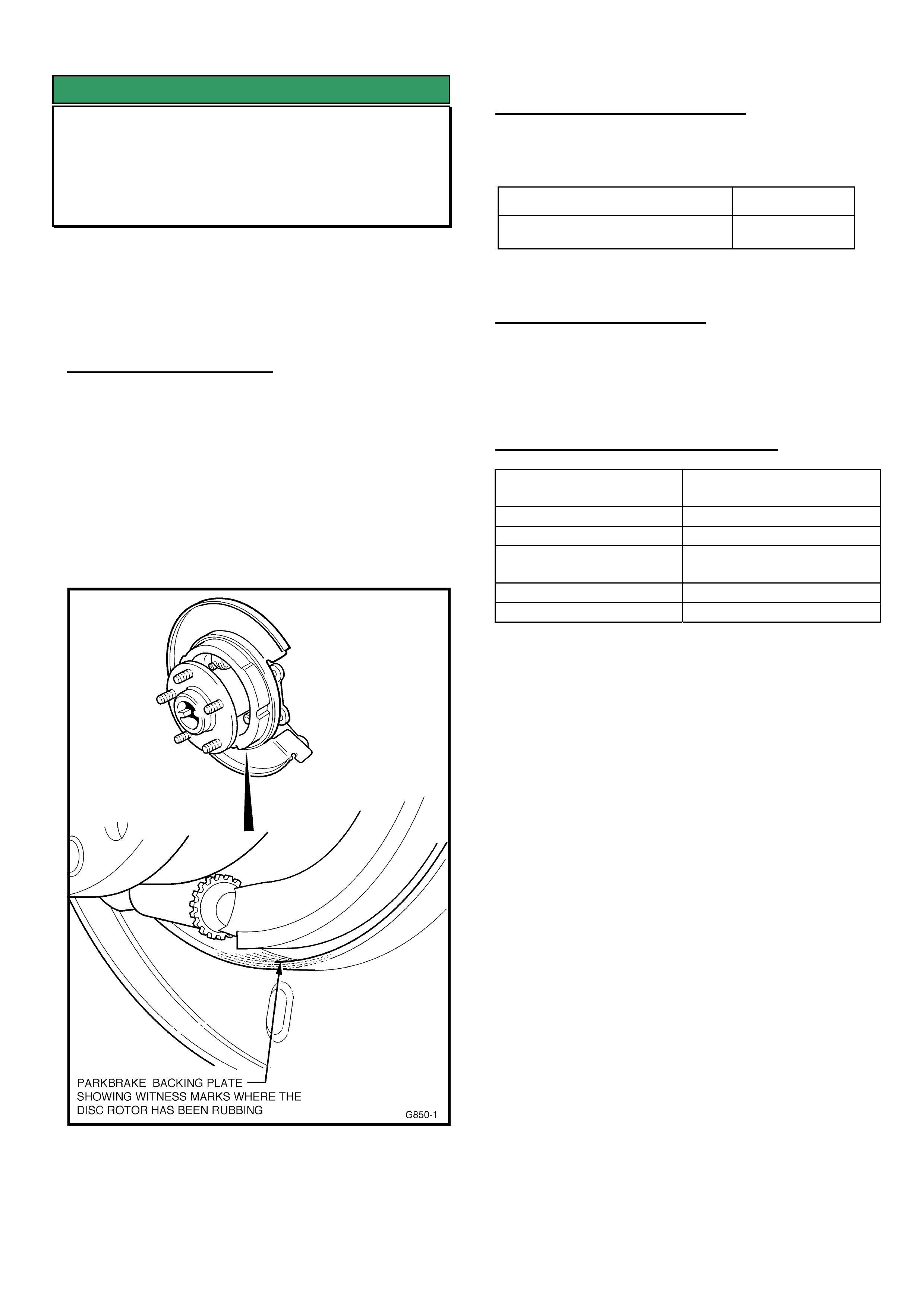
PROBLEM DESCRIPTION
Some vehicles may experience a scraping noise from
the rear brakes when loaded, cornering or travelling
over bumps at low speed.
Investigations show this noise is caused by the disc
brake rotor scraping on the backing plate sealing
flange, because of insufficient clearance. Figure 1
below shows typical rear backing plate “scrape”
marks on the sealing flange - with disc brake rotor
removed
Figure 1.
PRODUCTION RECTIFICATION
Revised rear brake discs to provide clearance to the
backing plate were fitted from:
ISOVIN No.: Build Date:
6G1YK03F64L225326 23/01/2004
SERVICE RECTIFICATION
Summary: Machine the rear disc brake rotors as per
procedure on next page.
WARRANTY CLAIM INFORMATION
Description Remove, Machine & Re-
install Rear Brake Discs
Labour Op. No. H000257
Standard Time 0.4 hr
Add time for
Machining
0.4 hr
Failure Code 31
Failure Code NOW H0031 Poor Machining
NOTE: If machining is sublet, claim expense in “net
items” column. Please note that add times cannot be
claimed when work is sublet
HOLDEN SERVICE TECHLINE _____________________________________________________________FEBRUARY, 2004
12
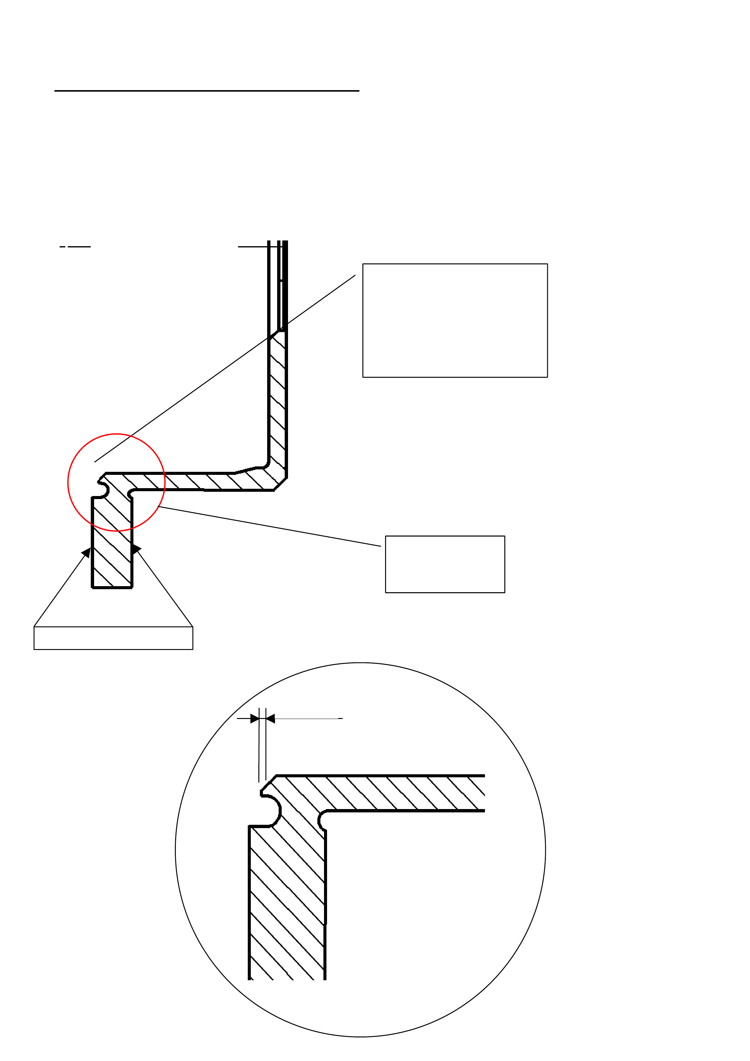
REAR BRAKE DISC MACHINING PROCEDURE
1. Prior to removing brake discs ensure they are marked with side of vehicle and stud position, so that on re-
installation they are put back in the same position. This is to ensure that the least possible installed runout is
achieved.
2. Machine inner lip of the disc as per the drawings below.
3. Re-install brake discs.
1mm
±
Remove 1 mm of material
parallel to the disc friction
surface. See enlarged figure
below for detail. This is to
increase clearance between the
rotor and dust shield to
eliminate scra
p
e
Brake disc section
where machining is
required
Centre line of disc
Friction surfaces of disc
HOLDEN SERVICE TECHLINE _____________________________________________________________FEBRUARY, 2004
13
SERVICE FIX
Ignition Module Failure
XC & Z14XE
(GROUP 6Y) TL0611-0401
PROBLEM DESCRIPTION
On some vehicles the ignition coil module may fail
causing the engine to misfire and/or the vehicle not to
start. Diagnostic Troubles Codes P0300, P0301,
P0302, P0303, P0304 may be logged.
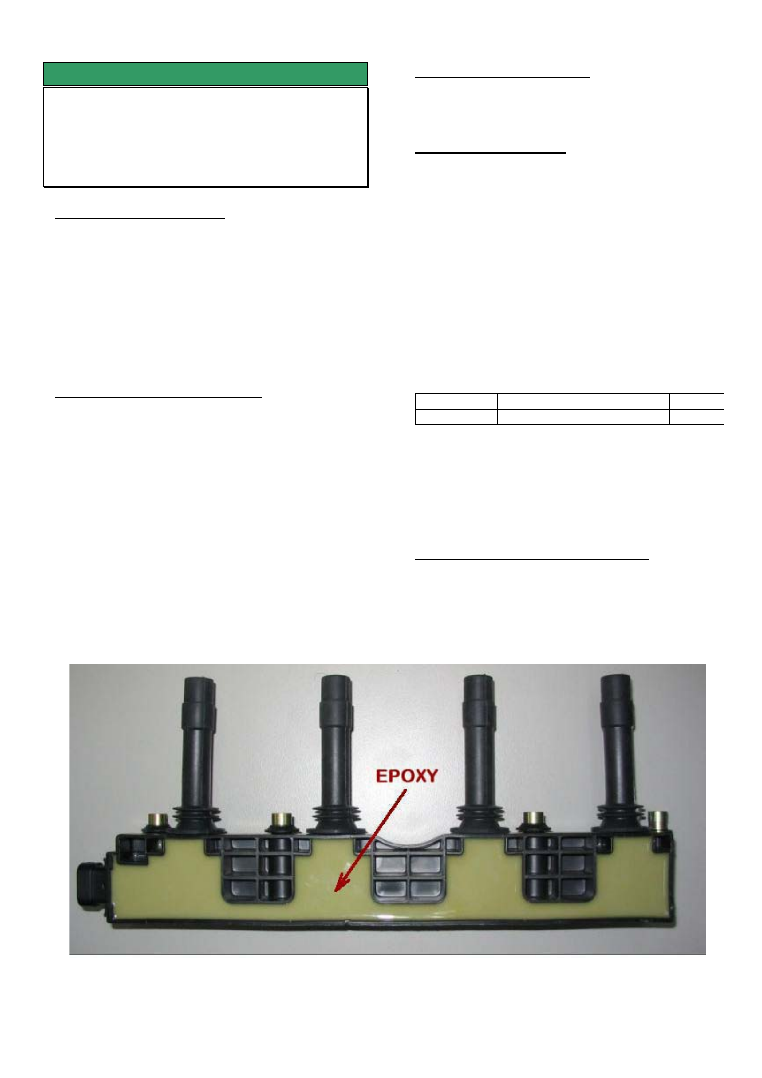
This problem is caused by the epoxy in the ignition
module becoming brittle and cracking, resulting in
internal arcing.
PRODUCTION RECTIFICATION
The corrective action for this problem has been to
replace the epoxy in the ignition module with a new
type of epoxy.
Revised ignition modules with the new epoxy have
been fitted to engines from engine Breakpoint
Z14XE20CB4883. (approx vehicle build date 10th
Oct 2003)
SERVICE RECTIFICATION
On vehicles where the ignition module has failed, fit a
new module from HSPO.
PARTS INFORMATION
NOTE: The new ignition module part number remains
the same.
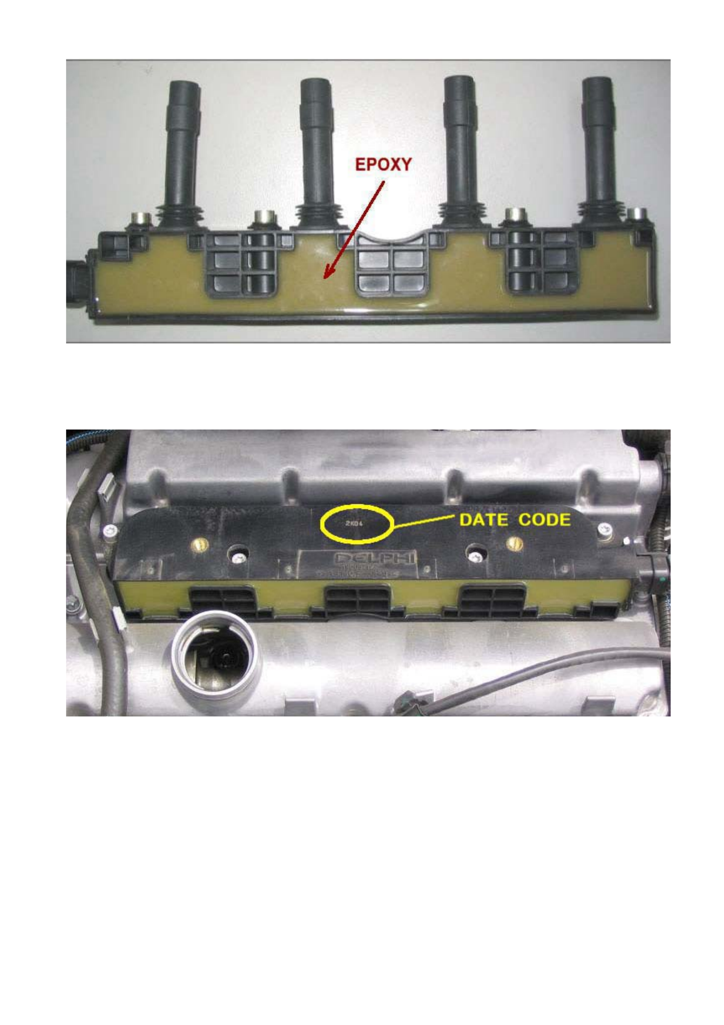
The new ignition module can be identified by the
epoxy colour which is darker, and the date code
stamp. Refer Figure 2.
The date code is stamped on the top of the ignition
module (as seen in Figure 3).
The new module can be identified by a date code that
is post (after) 3J22.
where: 3 = 2003, J = September, 22 = Day
Part No.: Description: Qty:
19005212 Module – direct ignition 1
Attention Parts Managers:
Any ignition coils prior to breakpoint should be
returned to HSPO for credit via the CRRM system.
WARRANTY CLAIM INFORMATION
Use Labour Times information in Warranty
Information section of current PV SIP CD
Figure 1. Old module has light coloured epoxy
HOLDEN SERVICE TECHLINE _____________________________________________________________FEBRUARY, 2004
14
Figure 2. New module has dark coloured epoxy
Figure 3. Location of date code
HOLDEN SERVICE TECHLINE _____________________________________________________________FEBRUARY, 2004
22
DIAGNOSIS HINT
Dash Panel Creak – Glue Track Region
VY Utility & V2
(GROUP 1) TL625-0401
PROBLEM DESCRIPTION
While driving through uneven driveways or on
acceleration and braking a creak may be heard from
the lower dash area.
This creak noise may be due to dash panel sheet
metal contact within the “glue track” in the
transmission tunnel area.
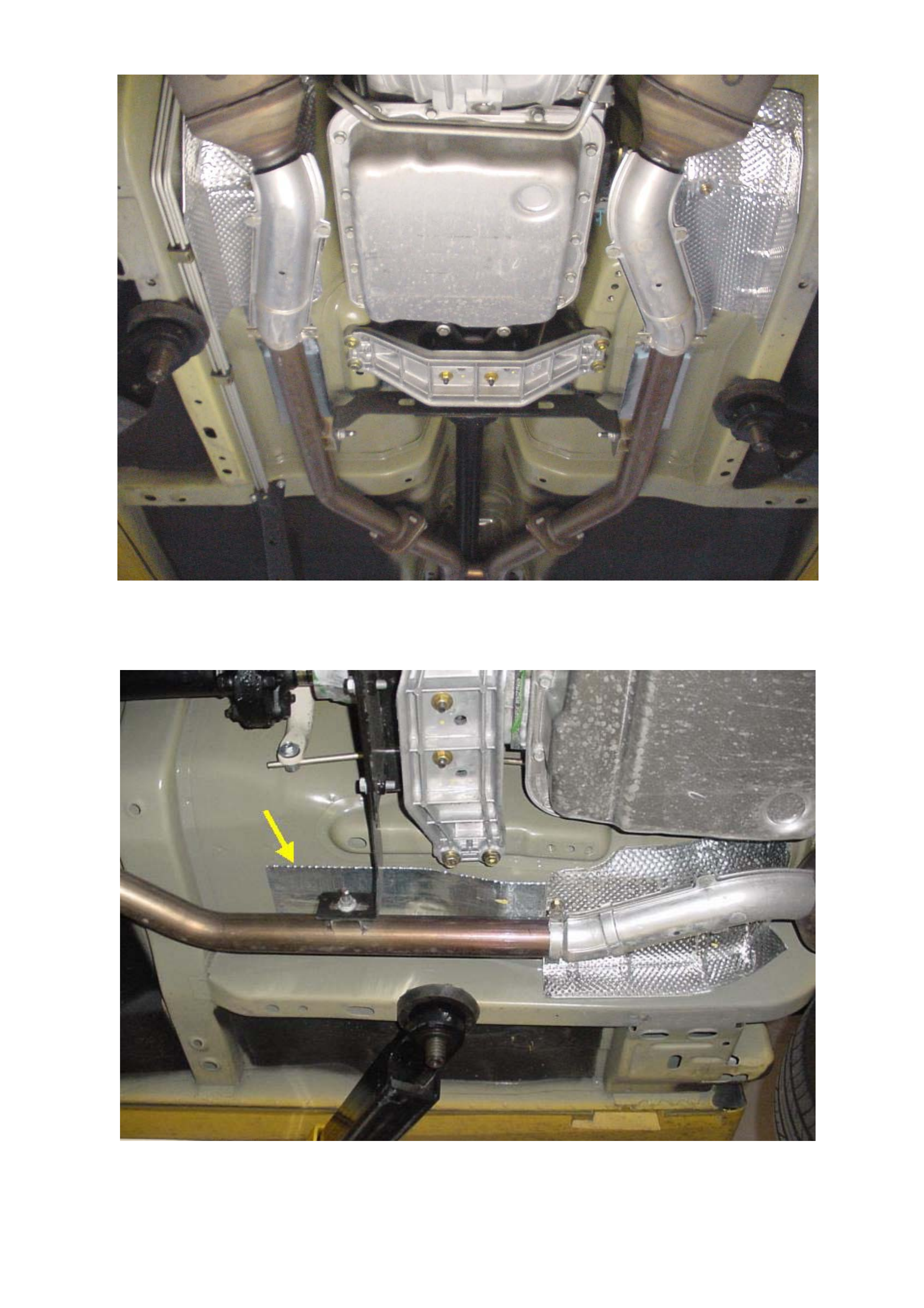
SERVICE RECTIFICATION
To rectify vehicles with the above condition:
1. Attempt to reproduce the noise by jacking the
vehicle from one side at the recommended jacking
points.
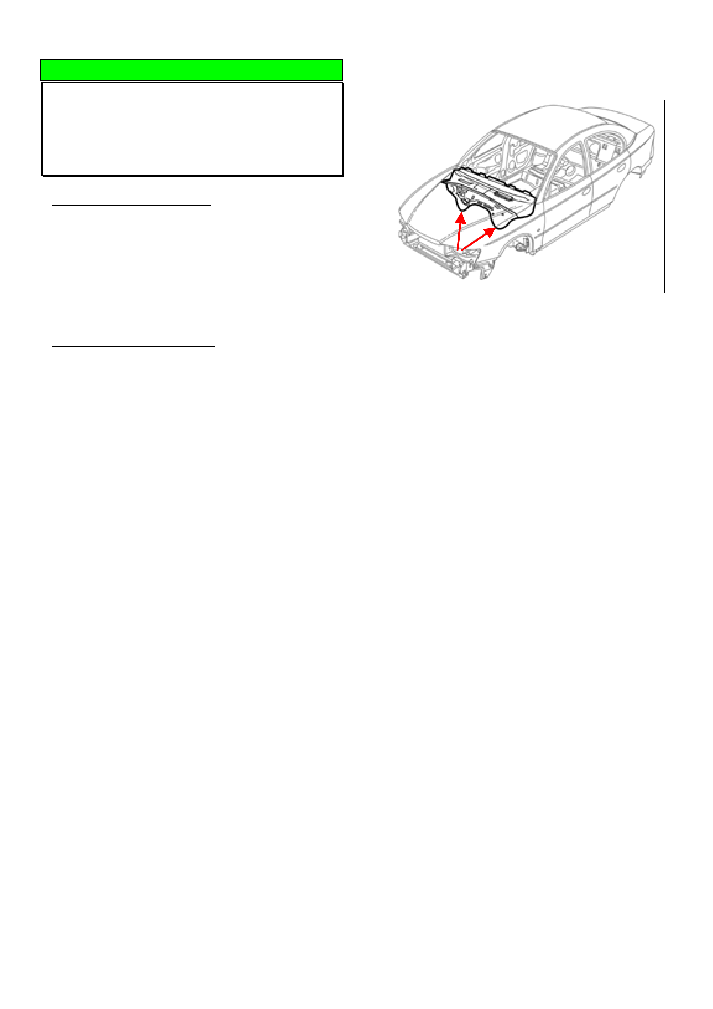
2. Confirm that the noise is loudest on the glue track
in the transmission tunnel area (between the arrows
in Figure 1) using either chassis ears or a
stethoscope.
Note: Reproducing the creak while stationary may
not be possible in every case. The sensitivity of the
listening device will also affect the ability to
reproduce the creak.
Figure 1.
3. After confirming the creak is coming from the
transmission tunnel area (between the arrows in
figure 1), use a pry bar from inside the vehicle to
widen the glue track sufficient to separate the two
panels, starting at the area where the creak was
identified.
4. Confirm that the creak has been eliminated by
repeating step 1.
5. Fill the “widened” glue track with RTV 732
silicone sealer to prevent the creak from returning
and to ensure the join is sealed.
NOTE: Sufficient access to the transmission tunnel
may require removal of the HVAC unit.
HOLDEN SERVICE TECHLINE _____________________________________________________________FEBRUARY, 2004
23
SERVICE FIX
Front Exhaust On-Pipe Heat Shields
Vibrate
WK, VYII, V2 with Gen III
(GROUP 8) REVISED TL514B-0401
This Techline supercedes the previous techlines
TL514-0306 & TL514A-0308. It includes revised
service fix and parts information.
PROBLEM DESCRIPTION
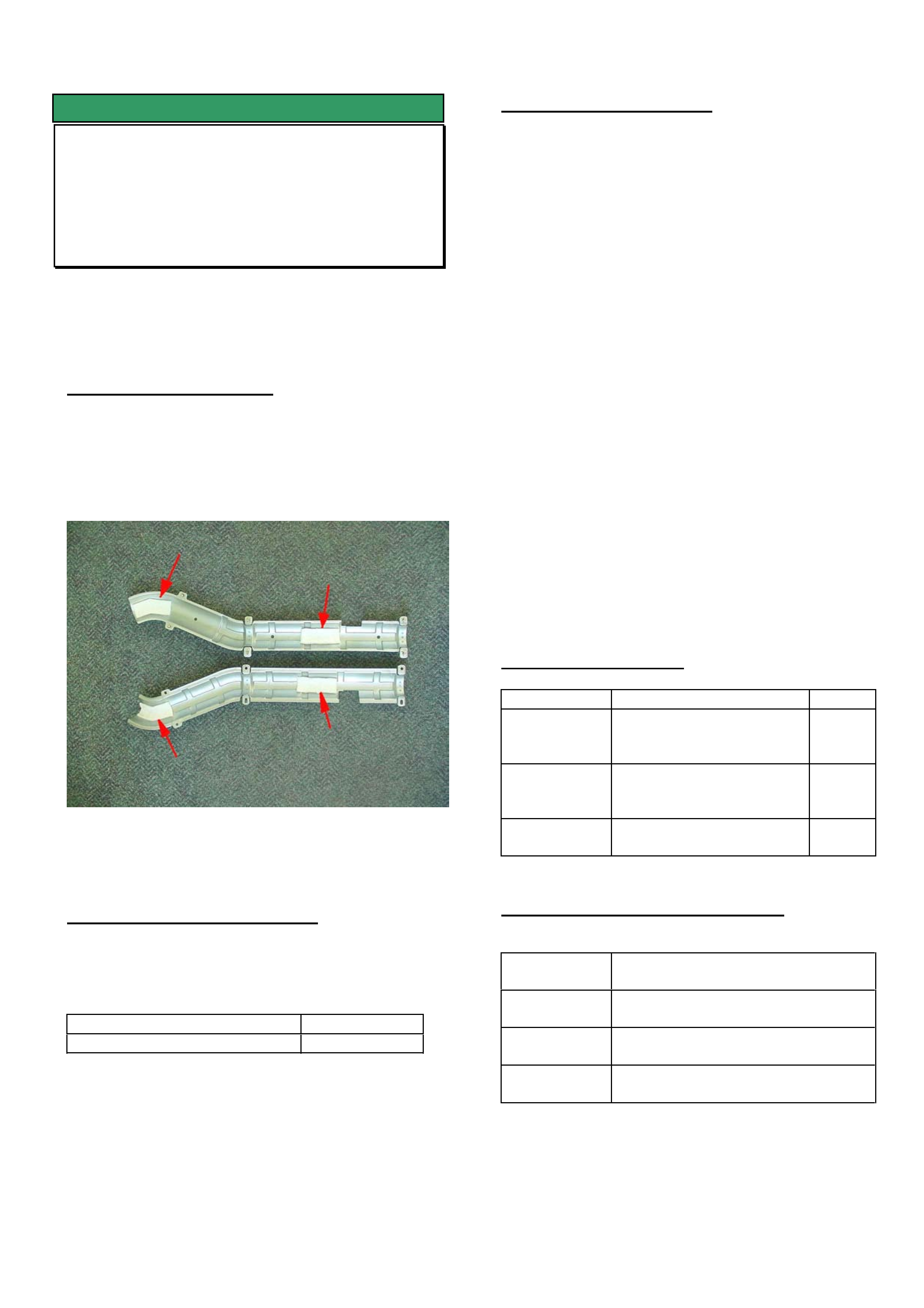
A buzz/vibration from front exhaust pipe heat shields
(long type) which occurs on takeoff under light loads
such as driving uphill.
The insulator pads adhered to the inside of the heat
shields may have become detached.
Figure 1. Shows insulation pads adhered to inside of
long-type heat shields.
PRODUCTION RECTIFICATION
The long type heat shields were replaced with
shorter heat shields and underfloor reflective foil
insulators from:
ISOVIN: Build Date:
L172001 12/9/2003
NOTE:
On-pipe heat shields and underfloor stick-on
reflective foil insulators have been removed from all
vehicles with Gen III engines built from 9/1/04. All
vehicles built from this date are fitted with floor
mounted “bolt on” type heat shield.
SERVICE RECTIFICATION
Summary: On complaint vehicles featuring the long
type on-pipe heat shields install new shorter on-pipe
heat shields as per following procedure.
1. Remove existing long-type exhaust heat shields.
2. Check if there are underfloor stick-on reflective
foil insulators located as shown in Figure 2. If
not, order new part 92056511 and install as
follows
.
(a) Clean underfloor area using a solvent
soaked rag to remove any dirt, sealer or paint
overspray.
(b) Soften the new reflective foil insulator by
heating with a heat gun to approximately 40 deg C.
(c) Wearing heat resistant protective gloves,
peel the adhesive paper from the reflective foil
and apply to the underfloor area in-line with the
exhaust pipe as shown in Figure 2. Smooth out
any bubbles.
3. Install new short-type heat shield kits 92210214
and 92210217 as shown in Figures 1 & 2.
PARTS INFORMATION
Part No.: Description: Qty:
92210214 Exhaust heat shield kit –
RHS (2 halves plus 4
nuts)
1
92210217 Exhaust heat shield kit –
LHS (2 halves plus 4
nuts)
1
92056511 Heat shield - self
adhesive
1
WARRANTY CLAIM INFORMATION
Description Replace heat shields both sides
and install underfloor reflective foil
Labour Op.
No.
L000223
Time
0.5hr
Failure
Code
36 vibration
HOLDEN SERVICE TECHLINE _____________________________________________________________FEBRUARY, 2004
24
Figure 1. Shows installation of new shorter “on-pipe” heat shields
Figure 2 Close up view of LHS underfloor stick-on heat shield
HOLDEN SERVICE TECHLINE _____________________________________________________________FEBRUARY, 2004
25
SERVICE FIX
Rear Brake Groan/Graunch - Repeat
Failure After Dampers Have Been Fitted
TS & TT MODEL YEAR 2002 Fitted with
Lucas Calipers
(GROUP 5) TL0441-0401
The procedure below should only be followed after
the previously issued information in Service Techline
July 2002, Issue 6 for Rear Brake Graunch has been
carried out (i.e. fitting dampers).
PROBLEM DESCRIPTION
Some vehicles are reported as having the low
frequency graunch still evident even after the
dampers have been fitted as per Service Techline
July 2002, Issue 6.
This noise must not be confused with brake squeal,
drag or scraping. Therefore, to avoid misdiagnosis,
the complaint noise needs to be
demonstrated/reproduced to a Technician/Service
Manager to confirm it is the low frequency graunch.
Cause
The dampers are tuned to damp out a specific
frequency. Testing has revealed that on vehicles
where the graunch is still evident with the dampers
fitted, the components are vibrating at a frequency
that is slightly different to that which the damper is
tuned for.
PRODUCTION RECTIFICATION
Dampers fitted in production from :
ISOVIN: Build Date:
W0L0TGF3535043736 27/09/02
Solid slide pins fitted in production from:
Calendar Week 36 (Sept) 2002.
SERVICE RECTIFICATION
Summary: Confirm complaint noise, confirm vehicle
has Lucas calipers, check damper installation, then
install solid slide pin kit.
IMPORTANT: Although the solid pin kit has been
successful in rectifying repeat graunch vehicles it will
not eliminate all brake noises. It is therefore vital to
confirm that the vehicle has the low frequency brake
graunch noise before proceeding to fit a solid pin kit.
Procedure:
1. Check that the damper to caliper attaching screw
has been set to the correct torque of 9-11Nm.
NOTE. Failure to check this torque may result
in the graunch noise remaining. Refer Figure 1.
Figure 1
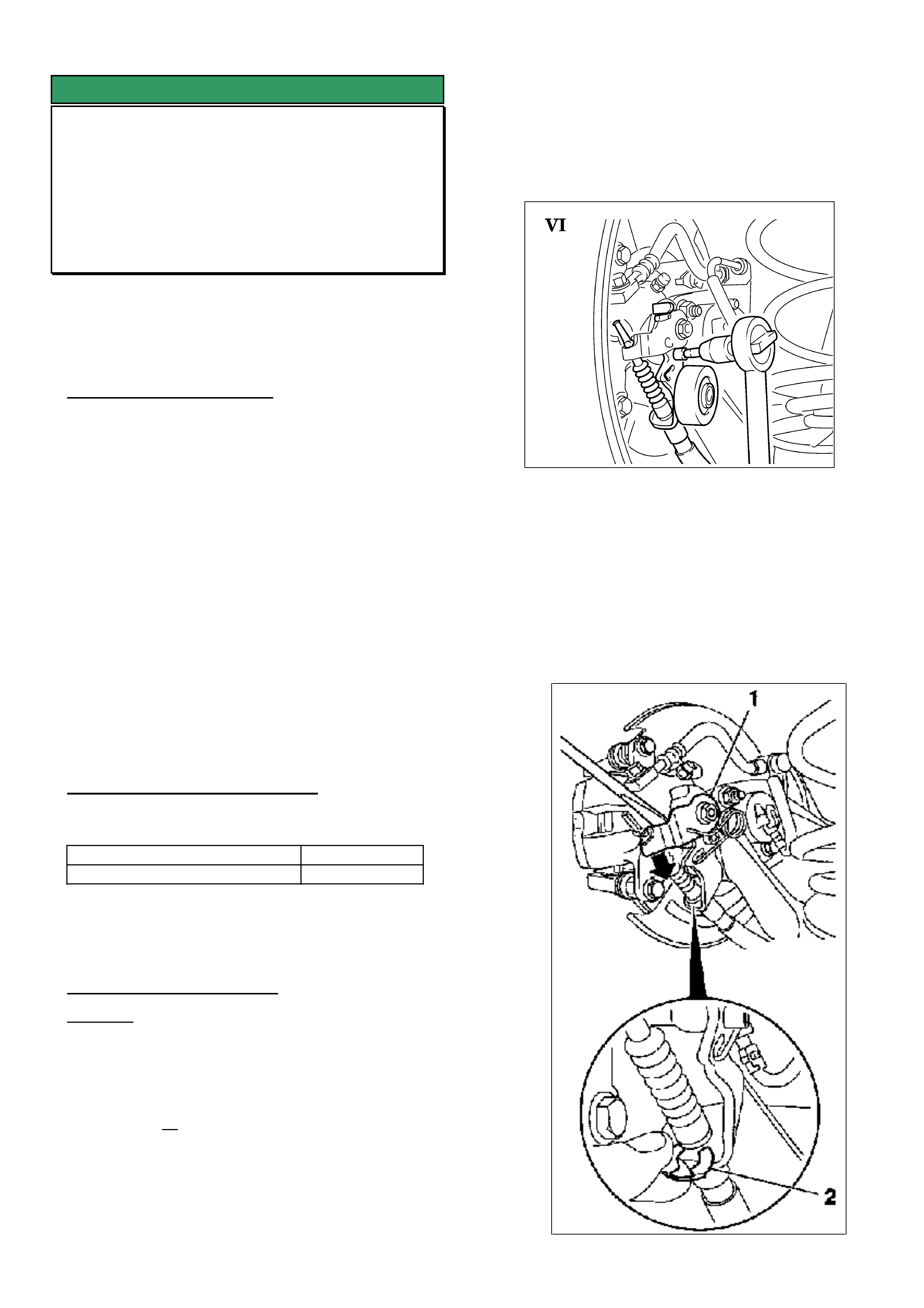
2. Release/disengage the park brake. Remove park
brake handle cover and release tension on the park
brake cable by unscrewing the adjustment nut.
3. Remove rear wheels.
4. Push brake caliper actuation lever (1) with a
screwdriver downwards in direction of arrow and
detach parking brake cable. Remove the retention
clip (2) and withdraw parking brake cable from
bracket. Refer Figure 2.
Figure 2
HOLDEN SERVICE TECHLINE _____________________________________________________________FEBRUARY, 2004
26
Solid Pin
Rubber Sleeved
Pin
Shim Grease
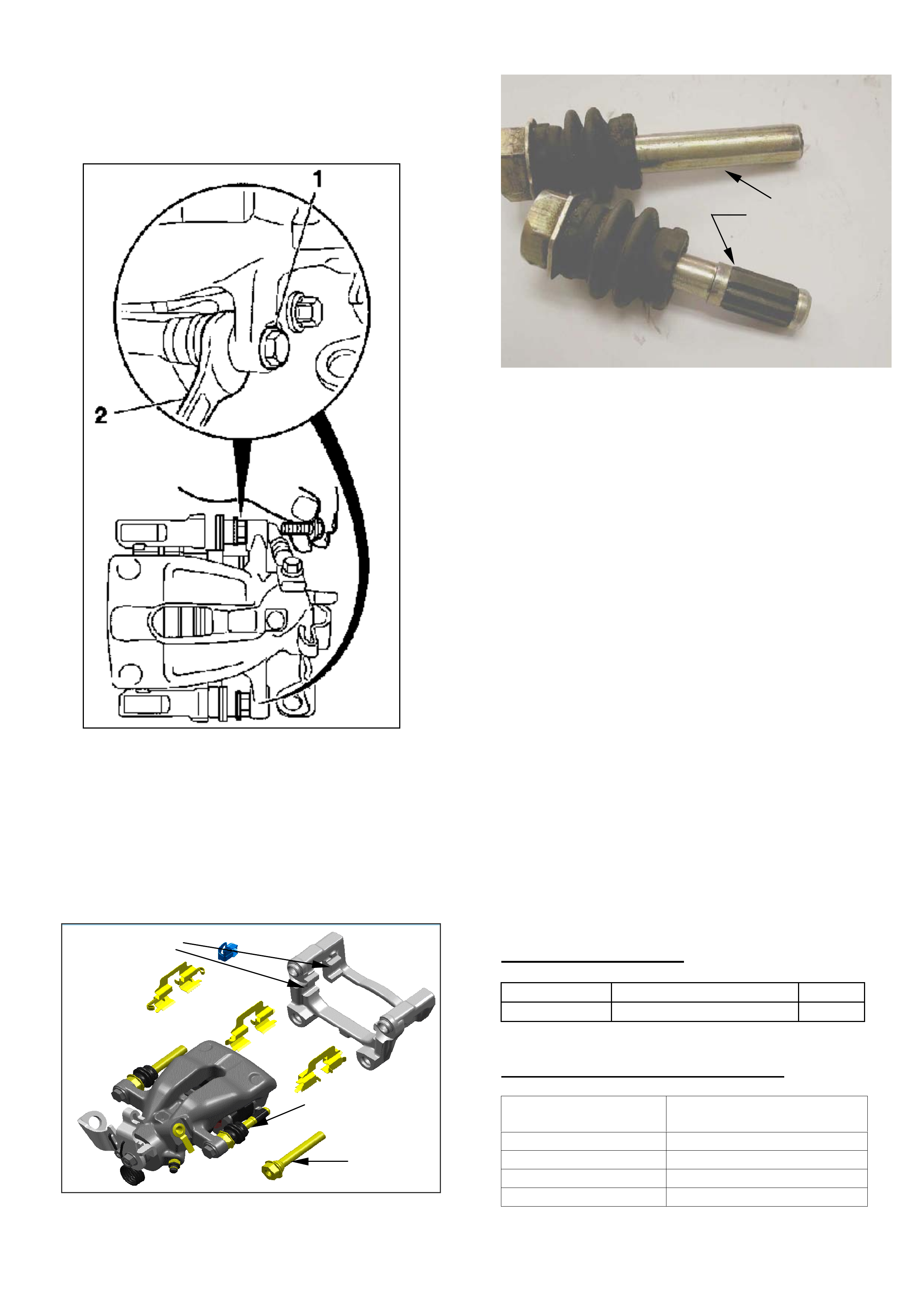
5. Remove fastening bolts (1) from brake calliper –
counterhold with open-ended wrench (2). Refer
Figure 3
Figure 3
6. Remove the rear brake caliper from brake carrier
and secure to the rear spring with cable ties or
suitable wire.
7. Remove carrier from vehicle.
8. Remove the caliper slide pins from the brake
carrier. See Figure 4.
9. Swap the rubber sleeved pin for a plain pin as
supplied in the kit. Refer Figure 5.
Figure 4.
Figure 5 Shows difference between pins
10. Coat slide pins with silicon type grease (Dow
Corning No. 44 or equivalent)
11. Install the slide pins into the brake carrier
12. Install carrier shims as supplied into carrier with
installation grease (p/n 32960041), making sure
the carrier is cleaned with a wire brush to remove
old grease prior to installation of the new shims.
Note: Grease is to go between the shim and the
carrier. It is not the same grease as the slide pin
grease.
13. Install the new pads ,as supplied, into the carrier-
do not remove the self adhesive backing paper
from the pad.
14. Install the brake carrier to the vehicle. Use thread
locking compound – tightening torque 100 Nm/74
lbf.ft.
15. Clean the caliper piston and fingers where the
pads contact the caliper.
16. If necessary retract caliper piston to allow for new
pads.
17. Remove backing paper from pads self adhesive
section and slide the caliper into position over the
pads.
18. Install new mounting bolts (as supplied) for brake
caliper to brake carrier – tightening torque 25 Nm /
18 lbf. ft.
19. Repeat for the other side of the vehicle
20. Adjust handbrake cable.
21. Confirm that graunch noise has been eliminated.
PARTS INFORMATION
Part No.: Description: Qty:
93176419 Solid Slide Pin Kit 1
WARRANTY CLAIM INFORMATION
Description Solid Slide Pin Kit
Installation – Both sides
Labour Op. No. H000243
Time 1.0 hr
Failure Code 40 Noisy
NOW Failure Code H0040 Noisy
Plain pin
Rubber sleeve pin
HOLDEN SERVICE TECHLINE _____________________________________________________________FEBRUARY, 2004
27
SERVICE PROCEDURE
LPG Mixer Removal and Reinstallation
Precaution
HBD fitted LPG
(GROUP 6C) TL0607-0401
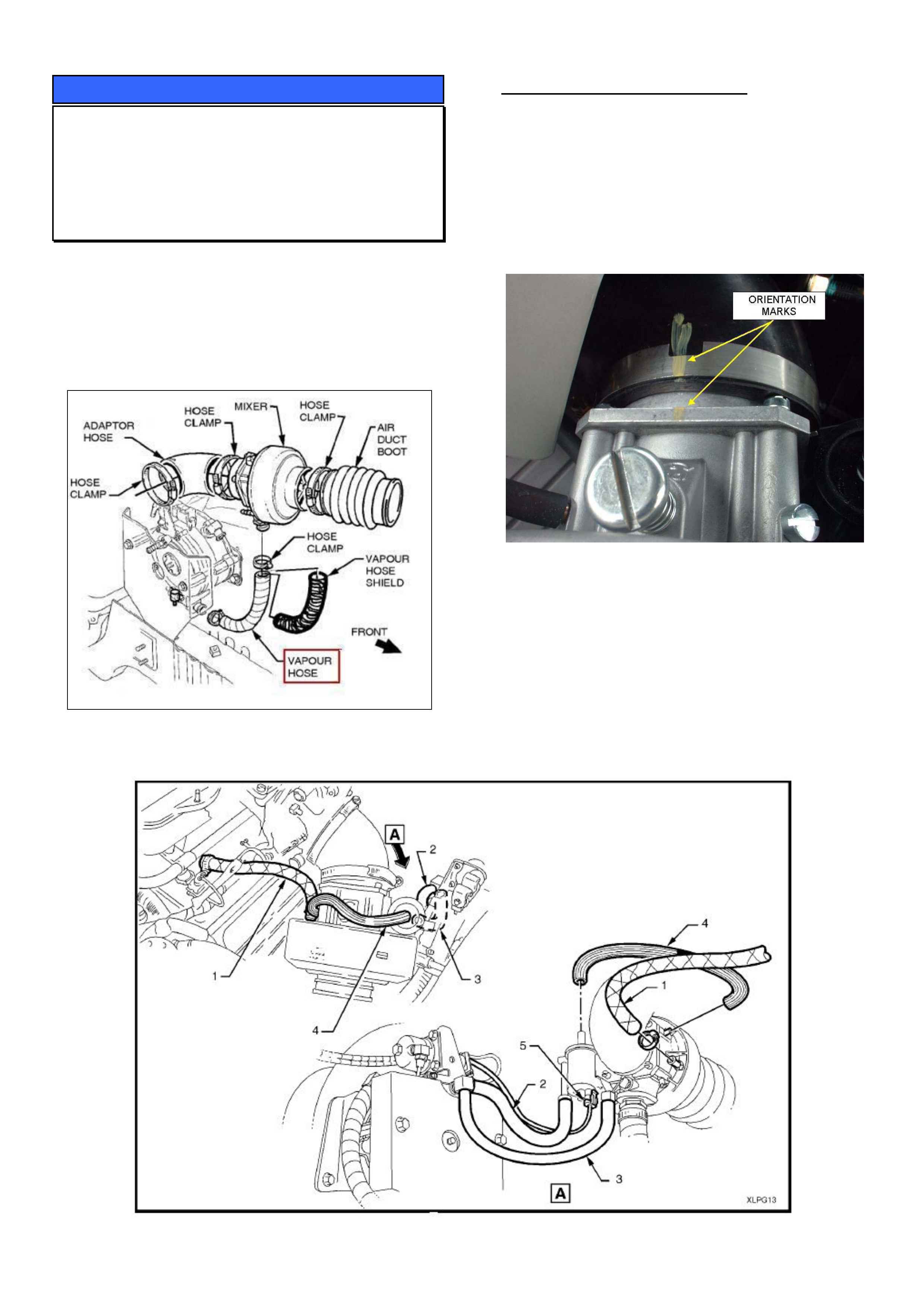
Whenever the LPG mixer is removed to service
spark plugs etc. it must be reinstalled in exactly the
same orientation it was in prior to removal. If the
mixer is twisted slightly from its original position, this
may result in the vapour hose fouling on the spark
plug leads. Figure 1 shows the parts in question.
Figure 1
SERVICE RECOMMENDATION
If the mixer is removed for any reason it should be
reinstalled in exactly the same orientation it was in
prior to removal. To ensure this happens, place
alignment marks on the mixer and elbow as shown in
Figure 2 prior to unclamping the mixer.
NOTE: Holden By Design (HBD) have been adding
alignment marks on the mixer and elbow as shown in
Figure 2 from July 2002.
Figure 2.
NOTE. Holden TAS report that they have had some
cases where the following DTCs have been set due
vacuum hoses (numbers 2 & 3 in Figure 3) being
swapped around when reinstalling the mixer.
P0132 - RH oxygen sensor signal voltage high
P0152 - LH oxygen sensor signal voltage high
Please ensure that these vacuum hoses are
reinstalled correctly if they are taken off when
removing the mixer.
Figure 3.
HOLDEN SERVICE TECHLINE __________________________________________________________________MARCH, 2004
5
INFORMATION
Gen III Oil Pan Drain Plug Sealing Washer
VY II
(GROUP 6A) TL0635-0402
At introduction of VY Series II, the engine oil pan drain
plug and sealing washer were revised as follows.
A. The plug changed from 13mm to 15mm hex.
B. The sealing washer was no longer available
as a serviceable part.
Therefore, when servicing vehicles do not remove
and discard the existing sealing washer from the plug.
Wipe the sealing washer to remove excess engine oil
and reinstall drain plug and washer assembly.
In the event the sealing washer is damaged, a
complete drain plug and washer assembly will need to
be fitted.
PARTS INFORMATION
Part No.: Description: Qty
11519408 Plug and seal assembly
oil pan drain A9W
1
NOTE: A9W is the production option code for
introduction of VY series II.
INFORMATION
Dana Contacts for Exchange Axles
V & W cars
(GROUP 4) TL0640-0402
Dana Automotive Systems Group is Holdens supplier
of V & W car rear and front drive axle units for vehicle
production, and exchange axle units for warranty
replacement. Dana has recently changed address
and contact details are as follows:
Dana Website
Dana should be contacted on their Website for all
warranty axle exchange requests and LSD “chatter”
kits.
For use of the Dana Website refer to Dealer Letters
DL 54/01 and DL 83/02.
Dana Website address is:
http://www.spiceraxle.com.au
Axle Warranty Enquiries
For any issues relating to supply of exchange axle
units not addressed by the Website – contact:
Robert Linton : (02) 9892 9237, Fax: (02) 9892 9310
Michael Morgan: (02) 9892 9343, Fax: (02) 9892
9442
Address Details
Dana Automotive Systems Group
205 - 231 Fairfield Road (Cnr. Foray Street)
Yennora, NSW 2161
These details will be updated in the next issue of
Passenger SIP.
INFORMATION
SPS Programming and Linking
All Models
(GROUP 0B) TL0664-0402
TAS receive many calls from retailer technicians who
run into problems when trying to perform the
"Program Immobiliser Function" or PCM to BCM link.
Please be aware that if you are installing a new
PCM/ECU you must do SPS programming before
carrying out the above.
This is only required for new PCMs/ECUs.

HOLDEN SERVICE TECHLINE __________________________________________________________________MARCH, 2004
6
DIAGNOSIS HINT
Interior Light Fuse Blows or Interior
Lights Staying On
VY / V2 / WK
(GROUP 12) TL0639-0402
CONDITION
Interior light fuse (number 6) blows or interior lights
stay on.
DIAGNOSIS HINT
If presented with a vehicle having either of above
conditions, it is recommended that the following areas
be inspected (in the order shown) for possible wiring
damage prior to performing the standard diagnosis.
1. The driver’s and passenger’s sun visor pivot area.
2. Rear map lamps (above the passengers doors).
3. Passenger door light switch circuit trapped behind
the PCM / PIM mounting bracket.
4. The wiring around the key reader slip ring.
5. Door sill screws holding the sill trim panels on.
6. Upper B pillar, B pillar trim clips or seat belt
bracket.
DIAGNOSIS HINT
Centre Rear Seat Belt Cannot Be
Withdrawn
ZC
(GROUP 1) TL0656-0402
A Retailer call to TAS has highlighted the following
issue relating to the operation of the centre rear seat
belt.
If the seat back is not correctly latched in the
vertical position, the centre rear seat belt “locks-
up” and cannot be withdrawn from the seat back.
Therefore, if a customer complains that the centre
rear seat belt has locked-up and cannot be
withdrawn, the first thing to check is if the seat back
is correctly latched in the upright position.
Please ensure that all your Service Advisors are
aware of this item.
HOLDEN SERVICE TECHLINE __________________________________________________________________MARCH, 2004
7
SERVICE PROCEDURE
Clutch Pressure Plate Bolt Torque
Revised
All with Gen III 6-Speed M/T
(GROUP 7A) TL0634-0402
The pressure plate bolt torque specification has been
revised in production to 70 +/- 7 Nm from:
ISOVIN: Built Date:
6G1VX12F04L234149 12/2/2004
NOTE: Whenever performing repairs to the clutch
assembly, ensure that the 6 pressure plate retaining
bolts are tightened in sequence as shown in PV SIP
and evenly over 4 stages until the correct torque is
reached.
CLUTCH PRESSURE PLATE
BOLT TORQUE SPECIFICATION.
Stage 1 15 Nm
Stage 2 35 Nm
Stage 3 55 Nm
Stage 4 70 Nm
Holden PV SIP will be updated at the earliest
opportunity to show this new specification.
SERVICE PROCEDURE
Revised Door Lock Knob Assembly
VYII, V2, WK
(GROUP 1) TL0636-0402
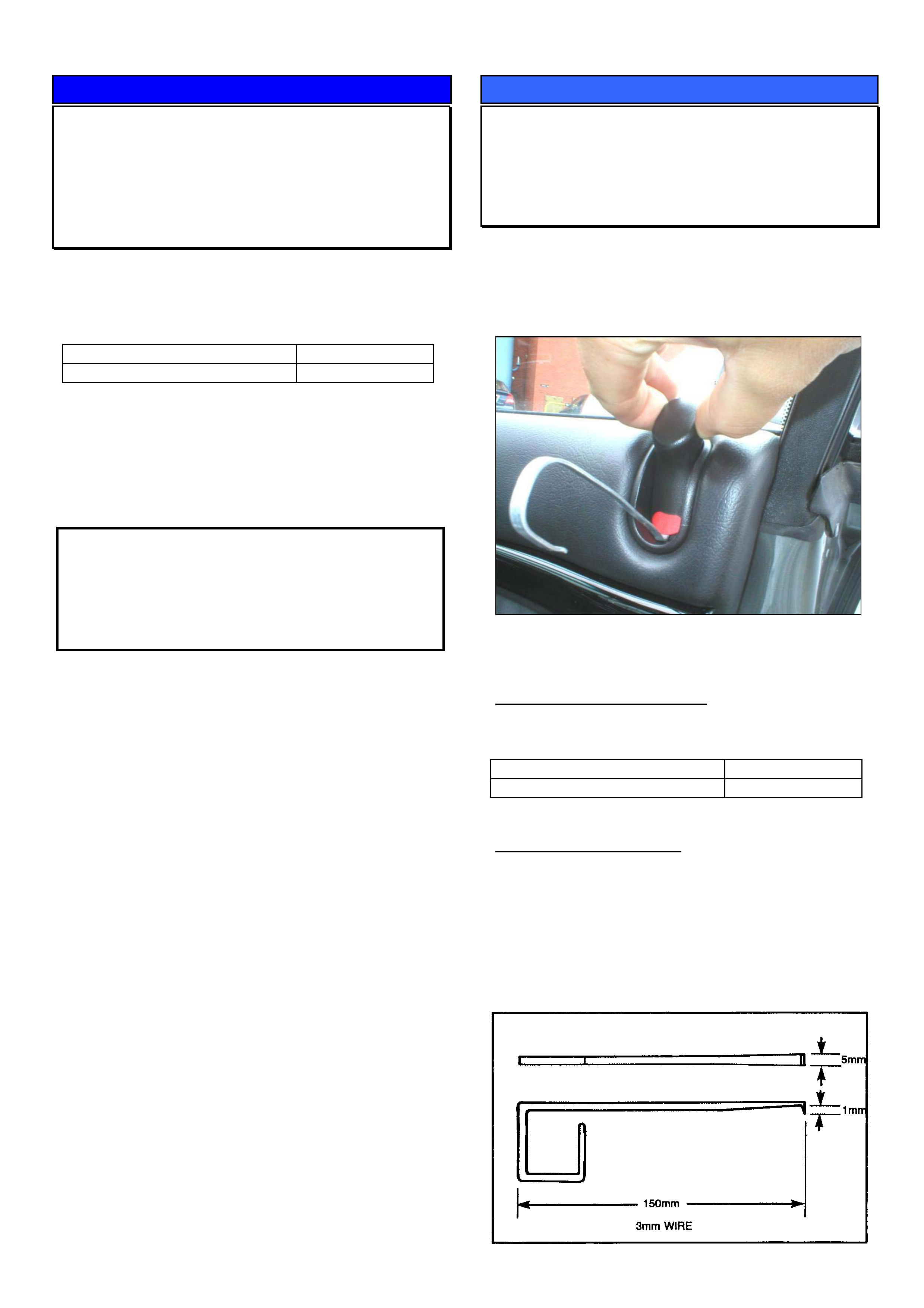
A revised door lock knob assembly has been
introduced which has a tool access slot added below
the red locking insert. This slot allows the red locking
insert to be released without damage. Refer Figure 1.
Figure 1. Shows a removal tool inserted into slot
below red locking insert.
PRODUCTION BREAKPOINT
Revised door lock knob assemblies with added
access slot have been fitted to vehicles from:
ISOVIN: Built Date:
L238377 18/2/2004
REMOVAL PROCEDURE.
1. Pull door lock knob up to reveal slot below red
locking insert.
2. Insert removal tool into slot.
3. Pull red locking insert outwards to allow door lock
knob to be withdrawn.
A removal tool can be manufactured from steel to the
following dimensions. (previously used for VN)
HOLDEN SERVICE TECHLINE __________________________________________________________________MARCH, 2004
8
INFORMATION
New design Blower Speed Controller for
ECC Vehicles
VYII, WK, V2
(GROUP 2) TL0642-0402
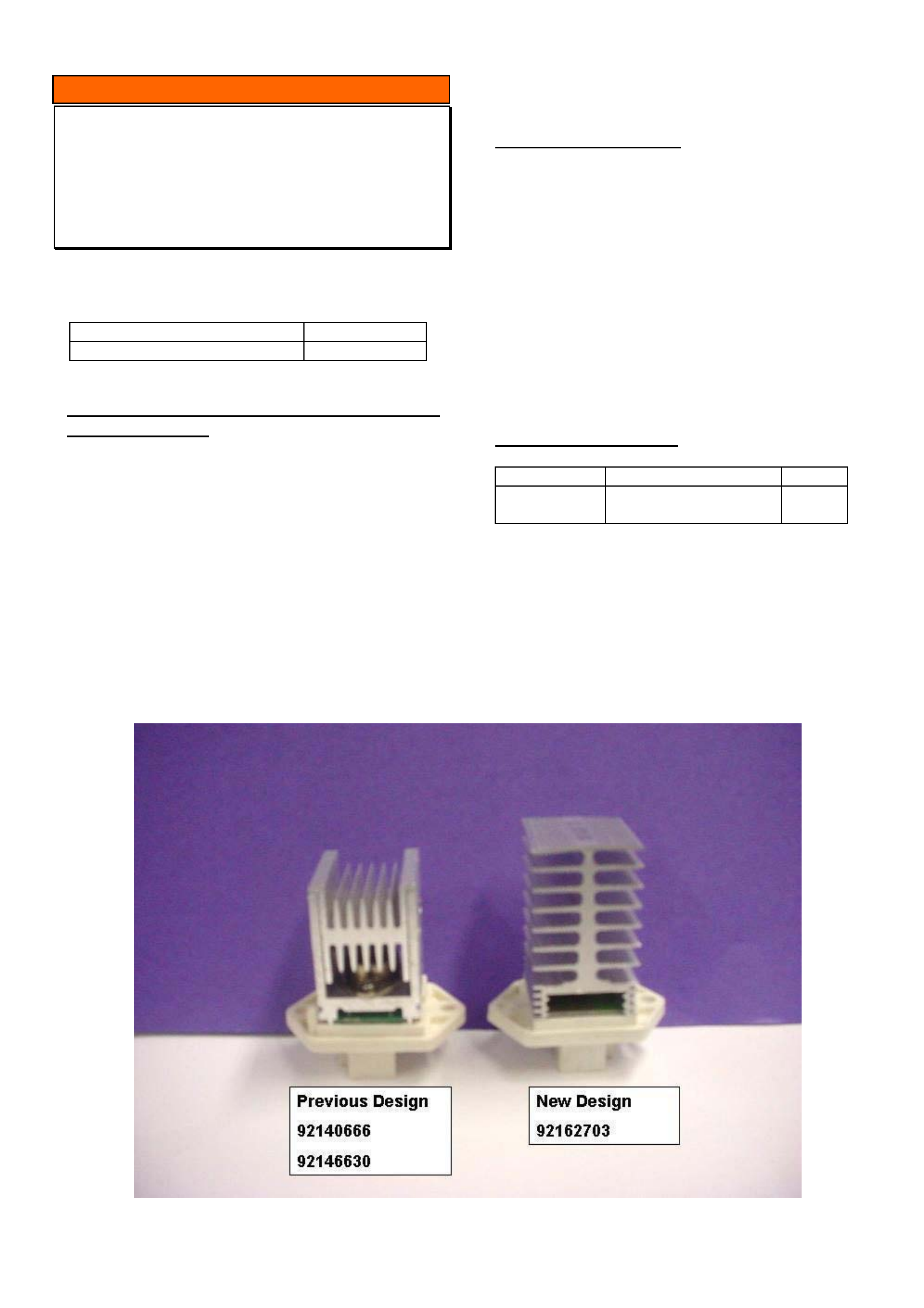
A new design HVAC blower speed controller has
been introduced into vehicles from:
ISOVIN: Built Date:
6G1YX54F44L236466 10/02/2004
Operating Characteristics Of New Blower
Speed Controller.
The main feature of the new blower speed controller
is an internal resettable circuit breaker. This circuit
breaker is to prevent damage to the blower motor
electrical circuit in the case of electrical current
surges, blower motor lock up on slower speeds or
extreme temperature build up.
If any of the above situations occur in the blower
motor circuit, the circuit breaker will open circuit and
render the blower motor inoperative.
The circuit breaker will reset after the ignition is cycled
from OFF to ON.
PROBLEM DIAGNOSIS
If a customer reports that “the blower motor switched
off while driving and resumed after the ignition was
cycled from OFF to ON do not replace the blower
speed controller as it has performed the function it
was designed for. Check the following:
- Blower motor and circuit for excessive current draw.
- Blower motor for foreign material caught in plastic
impeller.
In cases where the blower speed controller switches
the blower motor OFF regularly, and the above
checks do not reveal any abnormalities, replace the
blower motor as this could be the cause of excessive
current.
PARTS INFORMATION
Part No.: Description: Qty:
92162703 Blower Speed
controller ECC
1
The blower speed controller 92162703 can be used
as a replacement for previous controllers 92146630
and 92140666, from VT to VY.
Note that the new controller has 3 terminals whereas
the previous controllers had 4 terminals.

HOLDEN SERVICE TECHLINE __________________________________________________________________MARCH, 2004
9
SERVICE FIX
Blaupunkt Radio Speed Dependent
Volume Malfunction
TS / XC / ZC
(GROUP 12) TL0660-0402
This is advance service fix information. An updated
techline will be issued when Production Correction
information is available.
CONDITION
Customers may advise that the speed dependent
volume control feature does not function even when
the highest level of speed dependent volume control
is selected on the audio head unit.
CAUSE
The above condition is related to a change in the
software in Blaupuntkt audio head units from the
middle of 2003. The revised software can be
identified by adjusting the volume control; if the word
VOLUME is displayed, the head unit has the affected
software level.
CORRECTION in PRODUCTION
To be advised in a future techline
CORRECTION in SERVICE
To rectify customer complaints of this condition,
perform the following operation. Ensure that only the
PULSE setting is changed.
1. Turn radio off.
2. Push and hold number 5 and 6 buttons then
press ON.
3. Keep all three buttons pressed until the word
"Service" appears on the screen.
4. Release buttons.
5. Push "SEEK" button unit the word "PULSE 2"
appears on screen.
6. Push the "TUNE/TRACK" button left to reduce
setting to "PULSE 1".
7. Turn radio off then back on or leave for 10
seconds (Radio automatically exits service
mode)
NOTE: For reference, the configuration of
each parameter shown within the “Service” selection
should be as follows;
ZC Vectra equipped with a 2620 audio head unit
Range2
GID
MAXVOL40
P01 007
Pulse 1
ZC Vectra equipped with a 2020 audio head unit
Range2
10T CHAR
MAXVOL40
P01 007
Pulse 1
TS Astra equipped with a 520 audio head unit
Range2
MAXVOL40
P01 006
Pulse 1
XC Barina equipped with a 2020 audio head unit
Range2
MAXVOL40
P01 007
Pulse 1
HOLDEN SERVICE TECHLINE __________________________________________________________________MARCH, 2004
11
INFORMATION
Trailer Harness – Location of Electric
Brake Connection
AWD Adventra Wagon
(GROUP 0B) TL0647-0402
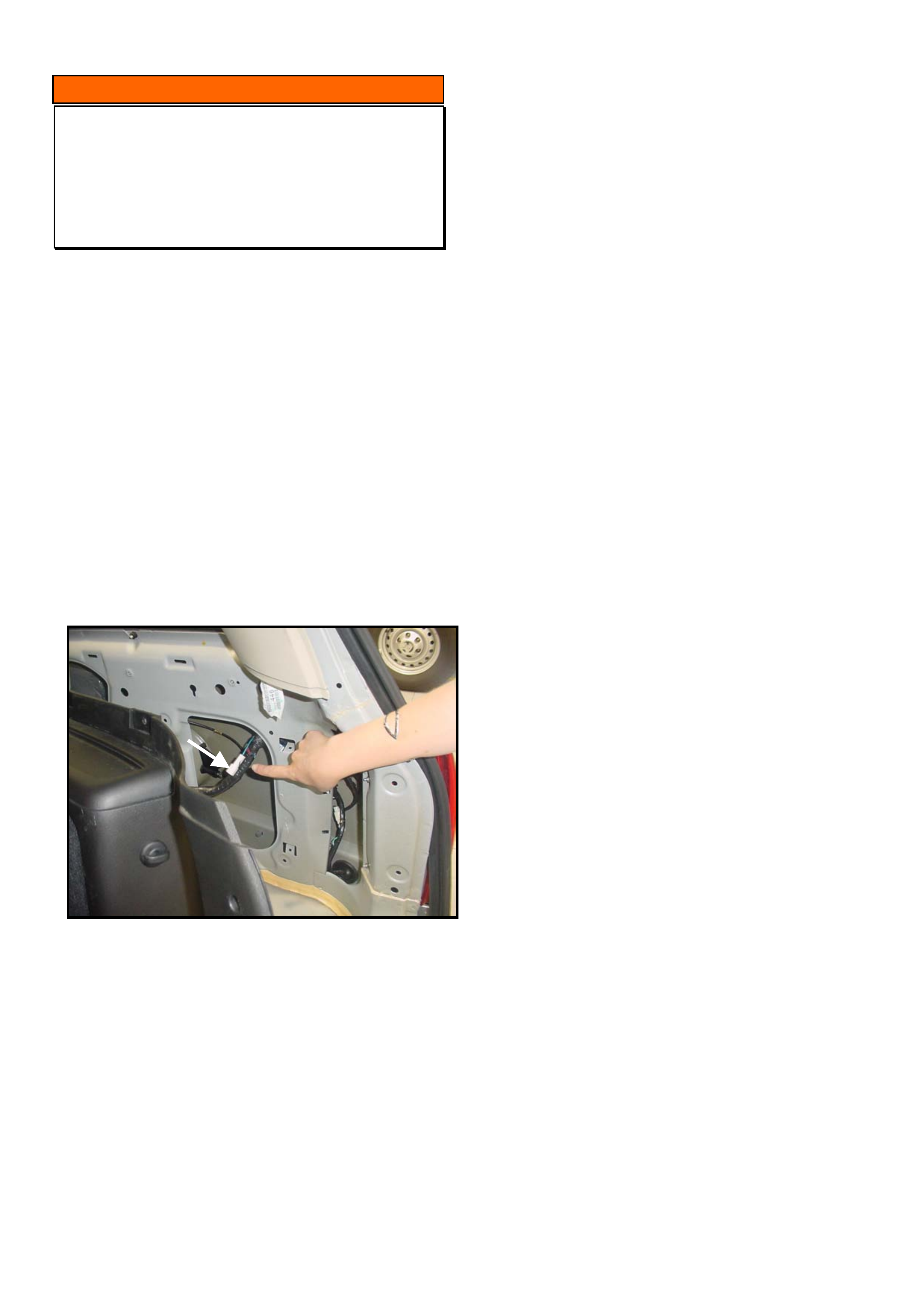
Trailer harnesses are fitted as standard equipment to
Adventra.
The trailer harness is connected to the vehicle wiring
harness behind the right hand tail light assembly.
The blue wire within the trailer harness used for
connecting electric brakes, has previously been tied
near the end of the harness connector. On Adventra,
this blue wire continues through the connector to the
vehicle harness and terminates approximately 10 -15
cm along the vehicle wiring harness behind the inner
rear panel / trim.
The wire and connector is taped to the vehicle
harness which is hidden behind the panel. Refer to
Figure 1 below.
Figure 1. Shows harness pulled down to reveal
electric brake connection.
HOLDEN SERVICE TECHLINE __________________________________________________________________MARCH, 2004
12
INFORMATION
Revision to Con Rod Big End
Manufacturing Process
All V6 3.8L Engines
(GROUP 6A) TL0650-0402
Commencing from Engine No. VA375970, fitted to
vehicle tag No. L179991, all 3.8L V6 engines are
fitted with connecting rods manufactured using the
latest powder forged metal technology and the “big
ends” are cracked apart in lieu of conventional
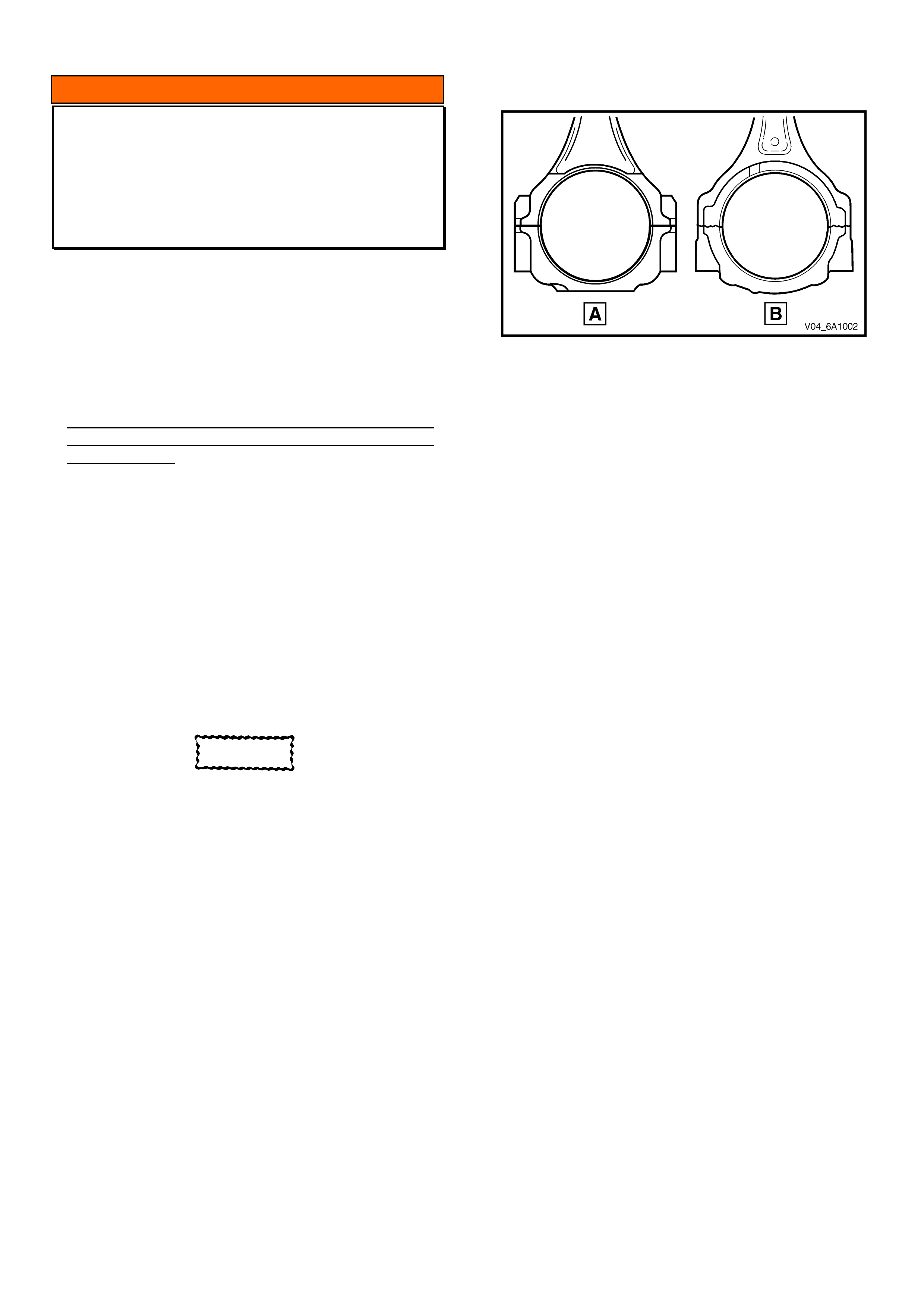
machining – refer illustration 6A2-1
The following information is provided for use by
technicians until the information is available in
Passenger SIP:
Powder forged cracked type connecting rods were
introduced into production as a running change
during September 2003. Illustration 6A2-1 shows the
difference in the early cast and machined type (A)
and later powder forged and cracked type (B)
connecting rods.
NOTE
Other than the revised manufacturing process and a
revised connecting rod cap bolt torque specification,
all other specifications and servicing procedures
relating to the connecting rods remain unchanged.
CAUTION
The early type connecting rods can be replaced
by the late type connecting rods.
However, to avoid confusion with having different bolt
torque values, when replacing early type connecting
rods with the late type, it is recommended that the
connecting rods be replaced as an engine set.
Illustration 6A2-1
Connecting Rods:
Early Type: Malleable Cast Iron 'I' Section
Late Type: Powder Forged ‘I’ Section
Length: (centre to centre)
Std V6 : 143.20 – 143.30 mm
S/C V6: 145.90 – 145.80 mm
Alignment: Bend 0.020/25.4 mm;
Twist 0.038/25.4 mm
Torque Wrench Specifications:
Early Type Connecting Rod (machined big
ends) Cap Bolts:
27 ±3 Nm plus 50 ±3° turn angle
Late Type Connecting Rod (cracked big ends)
Cap Bolts:
20 ±3 Nm plus 75 ±3 ° turn angle

HOLDEN SERVICE TECHLINE __________________________________________________________________APRIL, 2004
6
INFORMATION
Holden Contacts and Procedures
(GROUP OB) TL0679-0403
This techline summarises some of the Holden
contact procedures and gives a quick reference
guide for contact numbers.
Security information.
To obtain security information a completed security
information request form must be faxed through to
the security information department, as security
information cannot be given out by phone. TAS does
not process security information requests. Please
ensure you have the latest security information
request form, which is available on SIP. Contact
details are listed below. There can be up to a 4-hour
turn around on requests however if the information
needs to be obtained from overseas, it may take up
to 24 hrs. Do not phone the security information
department unless you have not received a response
in the normal turn around time. For further
information please refer to ADL 63/99.
Parts inquiries and information
If any information or assistance is required in regards
to part numbers or Partfinder, please refer to the
Holden Help section in Partfinder.
Warranty Authorisation and enquiries
Warranty can only be authorised by your Aftersales
District Manager. Labour times information is
available on SIP or from the warranty department.
For any other warranty inquiries please contact
Warranty Administration.
TAS
Technical Assistance Service (TAS) is a service
provided by Holden to assist Holden Dealers in
problem resolution.
TAS operating hours are:
Monday to Thursday 8.30am – 8.00pm and Friday
9.30am – 5.00pm Melbourne time. Contact to TAS
must be made by a Nominated Contact as outlined in
Section 5 of the TAS procedures manual. All
techlines, dealer letters and service information must
be checked prior to contacting TAS. The Nominated
Contact must not contact TAS until he/she has been
fully involved with the faulting vehicle and all Dealer
expertise has been exhausted. Problems should be
escalated through the Dealership to the senior
technician/foreman before contacting TAS.
TAS cases must be updated or closed within 30 days
unless a Dealer is waiting on a service fix to be
provided. It is the Dealers responsibility to update
cases. All cases should be recorded in the TAS
procedures manual, which should be referred to prior
to contacting TAS. Please note that an electronic
copy of the TAS procedures manual is also available
on passenger SIP.
Under no circumstances are TAS or other Holden
contact details to be supplied to customers or
independent repairers. TAS is a service restricted to
assisting Holden Dealer service departments.
Quick reference contact numbers
Air International Ph 1800 673 716
Australian Arrow Ph 03 9785 0792
Blaupunkt/Bosch Ph 1300 307 036
Clarion Ph 03 8558 1115
Fax 03 9551 0377
Customer Assistance Ph 1800 033 349
Dana Ph 02 9892 9237
Fax 02 9892 9310
www.spiceraxle.com.au
Delphi Ph 1800 335 777
Eurovox Ph 03 9237 0800
Fujitsu Ten Ph 03 9646 6008
Holden Assist Ph 1300 880 088
HSV Ph 03 9265 9500
Infomedia Ph 1800 810 103
Panasonic Ph 02 9986 7635
Petro-Ject Ph 02 9890 5701
Ph 02 9890 5244
Philips/Siemens-VDO Ph 1800 335 282
Salmat Ph 03 9358 2900
Security Ph 03 9647 2001
SPX Australia Ph 03 9544 6222
TAS Ph 1800 033 417
Fax 03 9647 2495
Warranty Ph 03 9647 1972
Ph 03 9647 2401
Ph 03 9647 1970
HOLDEN SERVICE TECHLINE __________________________________________________________________APRIL, 2004
7
DIAGNOSIS HINT
Electric Power Steering (EPS) Problems
Due To Poor Ground Point
XC Barina
(GROUP 9) TL0680-0403
Background Information
TAS has received calls from retailers regarding no
Tech 2 communication with the Electric Power
Steering (EPS), EPS light on in instrument cluster,
and/or repeat failure of the EPS module.
Investigation has found the EPS module high current
earth to ground point 4 at the drivers side A pillar, to
be loose, stripped or disconnected.
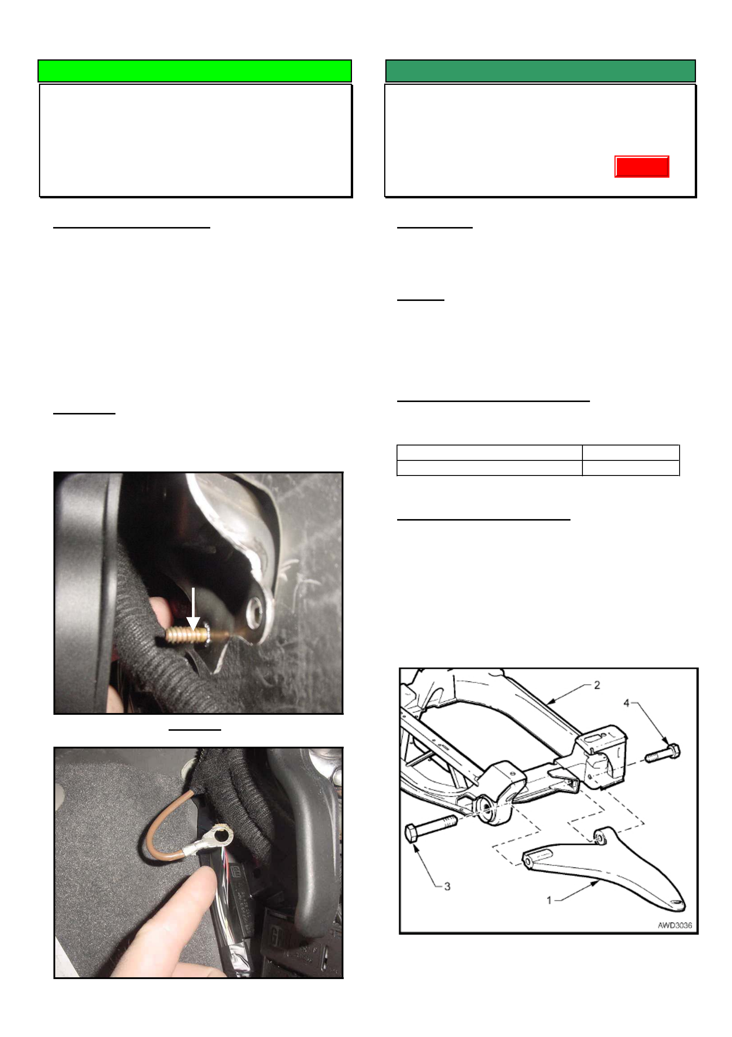
This ground point is located on a metal bracket to the
righthand side of the bonnet release lever as shown
in figure 1.
Important
When diagnosing any EPS related fault, check
ground point 4 retaining nut is fitted and tightened.
Figure 1
Figure 2.
SERVICE FIX
Front Suspension Clunk (Lower Control
Arm Rear Bush Movement)
VY Adventra
(GROUP 3) TL0638-0403
CONDITION
Clunk from front suspension usually heard when
wheel impacts deep pot hole.
CAUSE
One potential cause of front suspension clunk which
has been identified is movement of the control arm
bush in the cross member due to insufficient clamp
load.
CORRECTION – in Production
Front lower control arm bush rear bolt torque revised
on vehicles from:
ISOVIN: Built Date:
**********L237289 23/02/2004
CORRECTION – in Service
After verifying that vehicle has symptoms as
described above, increase torque on the front lower
control arm rear bush bolt to 175 – 185 Nm. Refer
bolt No. 4 in Figure 1.
Note. The bolt does not need to be replaced prior to
applying revised torque.
Figure 1.
B
O
N
N
E
T
L
E
V
E
R
Ground Point
4
Update
HOLDEN SERVICE TECHLINE __________________________________________________________________APRIL, 2004
8
SERVICE FIX
Front and Rear Accessory Mudflaps
Dislodge
TS
(GROUP 1) TL0675-0403
CONDITION
Accessory mudflaps become dislodged.
CAUSE
The mudflaps are attached to a metal mounting
bracket with plastic “heat stakes”. These joints may
be damaged in service which allows the plastic
mudflap to detach from its mounting.
CORRECTION
On any vehicle where the mudflaps become
dislodged as a result of damage to the “heat stakes”,
perform the following procedure.
Use fasteners P/N 92138352, to re-attach the
mudflap to the metal mounting bracket by simply
screwing the fasteners into the original heat stake
positions. Refer Figure 2
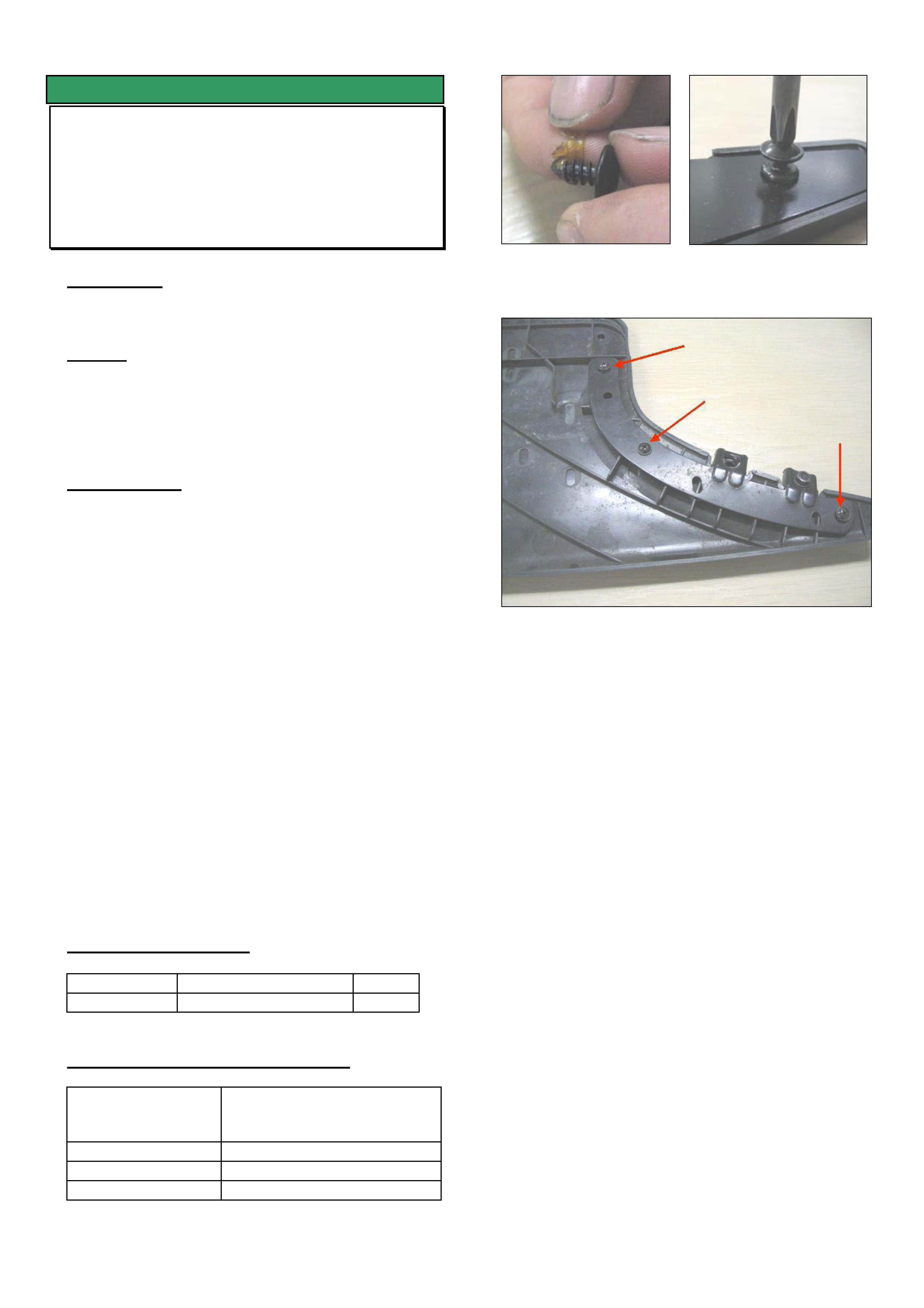
NOTE: The fastener tip is covered in a sealant
material which needs to be removed prior to
screwing into the plastic. (Refer Figure 1)
Add fasteners to each heatstake position regardless
of whether they are broken or not. This will ensure
the mudflap does not fail in the same manner again.
Front – 2 screws per mudflap
Rear – 3 screws per mudflap
NOTE: Fasteners, as described in this techline, will
be applied to all new Holden accessory mudflaps.
PARTS INFORMATION
Part No.: Description: Qty:
92138352 Screw 10
WARRANTY CLAIM INFORMATION
Description Attach mudflap to mounting
bracket with screws (4
mudflaps)
Labour Op. No. C000517
Time 0.4 hr
Failure Code 71 / C0071 Pulled loose
Figure 1. Remove
sealer from screw.
Figure 2. Screwing into
heatstake
Figure 3. Add a screw to each heatstake position.
HOLDEN SERVICE TECHLINE __________________________________________________________________APRIL, 2004
9
SERVICE FIX
Fuel Odour and Dust Entry
VU, VY Ute
(GROUP 8) TL0603-0403
ThisTechline should be read in conjunction with
Techline TL509-0308 (issue 8, Aug. 2003) which
provides sealing procedures for preventing dust/fuel
odour entering cabin.
PROBLEM DESCRIPTION
Customer complains of fuel smell in cabin usually
after the vehicle has been parked for some time.
Investigations show that small amounts of fuel
vapour may permeate the fuel filler hose and result in
a fuel odour.
PRODUCTION RECTIFICATION
An improved fuel filler hose with lower permeability
was installed into vehicles from
ISOVIN: Built Date:
**********L209199 4/12/2004
In addition to the above, expanding foam has been
added into the rocker panels (to prevent dust/fuel
odours entering the cabin) on vehicles from:
ISOVIN: Built Date:
**********L238316 17/2/2004
SERVICE RECTIFICATION
Summary: On complaint vehicles, replace the fuel
filler hose and seal the dust/fuel odour pathways in
body as per following procedure .
1. Replace fuel filler hose with new hose shown in
Parts Information.
2. On vehicles built before tag L238316,
(A) Seal all dust/fuel odour pathways as
described in Techline No. TL509-0308 (Issue 8,
Aug. 2003).
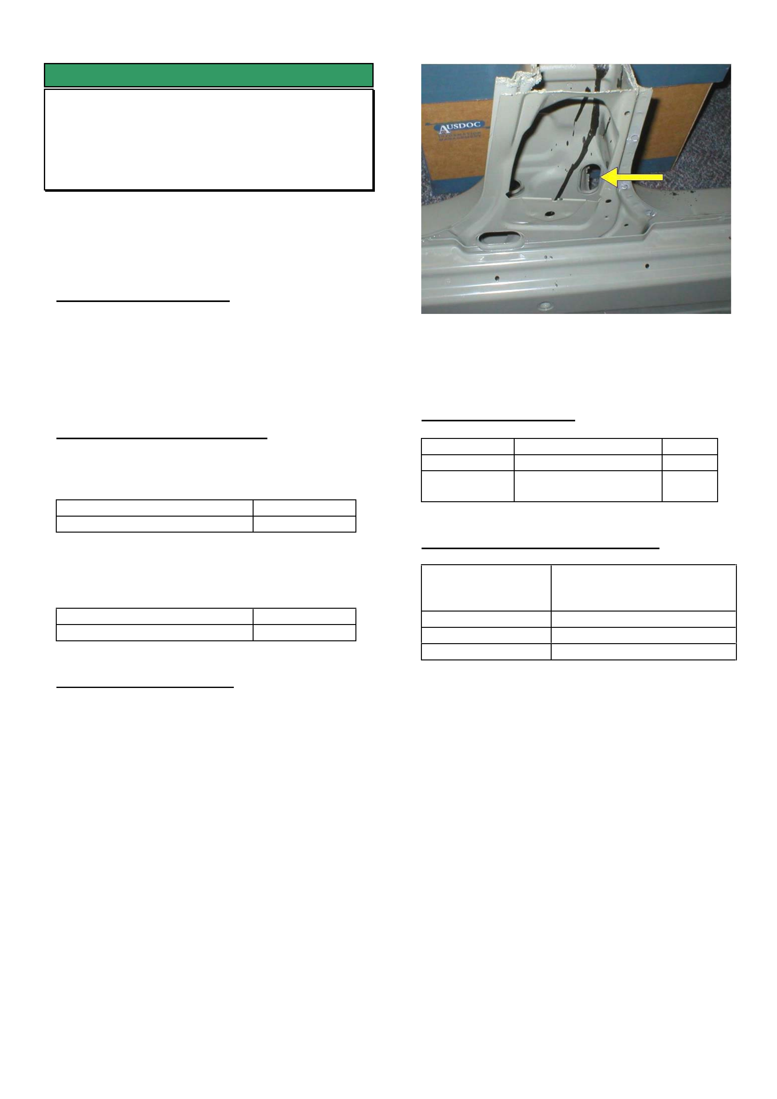
(B) Seal the hole in the sheetmetal at the base of
the drivers side B-pillar behind the seatbelt
retractor as shown in Figure 1. Seal the hole with
butyl patches cut from part No. 92156600.
NOTE: Vehicles built after tag L238316 do not
require above sealing procedures as they have
expanding foam inside the rocker panels to restrict
dust/fuel odours.
Figure 1. Section of lower RHS B-pillar showing oval
shaped hole (behind seat belt retractor) that requires
covering with a butyl patch.
PARTS INFORMATION
Part No.: Description: Qty:
92211421 Hose fuel filler 1
92156600 Deadener (butyl
patch)
1
WARRANTY CLAIM INFORMATION
Description Replace fuel filler hose and
add butyl patch to oval hole
in base of RHS B Pillar
Labour Op. No. L000226
Time 0.9
Failure Code 74/ L0074
HOLDEN SERVICE TECHLINE __________________________________________________________________APRIL, 2004
10
SERVICE FIX
Low Speed Engine Cooling Fan Relay
Sticking On
VYI, WK, V2 II With Gen III
(GROUP 12) TL0673-0403
CONDITION
Engine cooling fan remains on continuously after
ignition is switched off. In some instances the
vehicle battery may be fully discharged.
CAUSE
Contaminant on internal relay contacts due to a
quality control issue at the relay manufacturer.
Relays from the suspect batch were fitted to all
vehicles built between Jan 03 and Jul 03.
CORRECTION - Production
Known good relays were fitted to vehicles from:
ISOVIN: Built Date:
**********L145369 11/07/2003
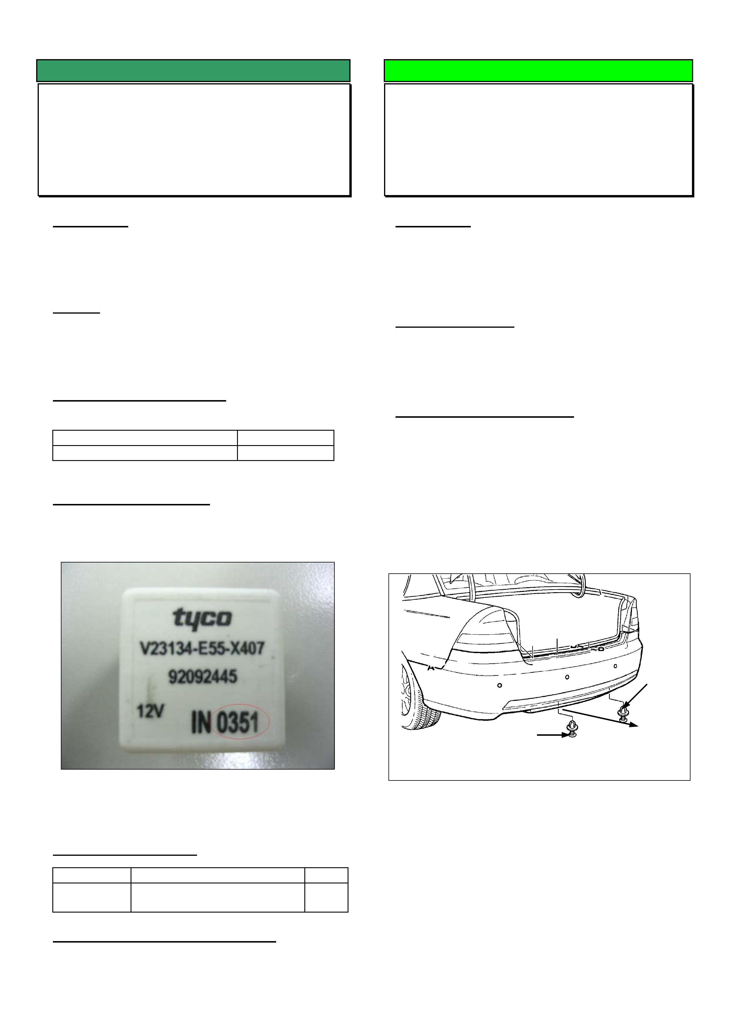
CORRECTION – Service
On vehicles affected by this condition, replace the
relay with one where the date code, as shown in
Figure 1, reads “IN 0314” or higher.
All relays manufactured prior to date code IN 0314
have been removed from HSPO stock.
PARTS INFORMATION
Part No.: Description: Qty
92092445 Low Speed Cooling Fan
Relay
1
WARRANTY CLAIM INFORMATION
Use Labour Times information in Warranty
Information section of current PV SIP CD
DIAGNOSIS HINT
False Triggering Of Reverse Park Aid By
Tow Ball
VY, WK, V2
(GROUP 12) TL0654-0403
CONDITION
Reverse Park Aid is triggered for no “apparent
reason, i.e. there are no objects within range behind
the vehicle
POSSIBLE CAUSE
The reverse parking aid sensors may be detecting
the tow ball.
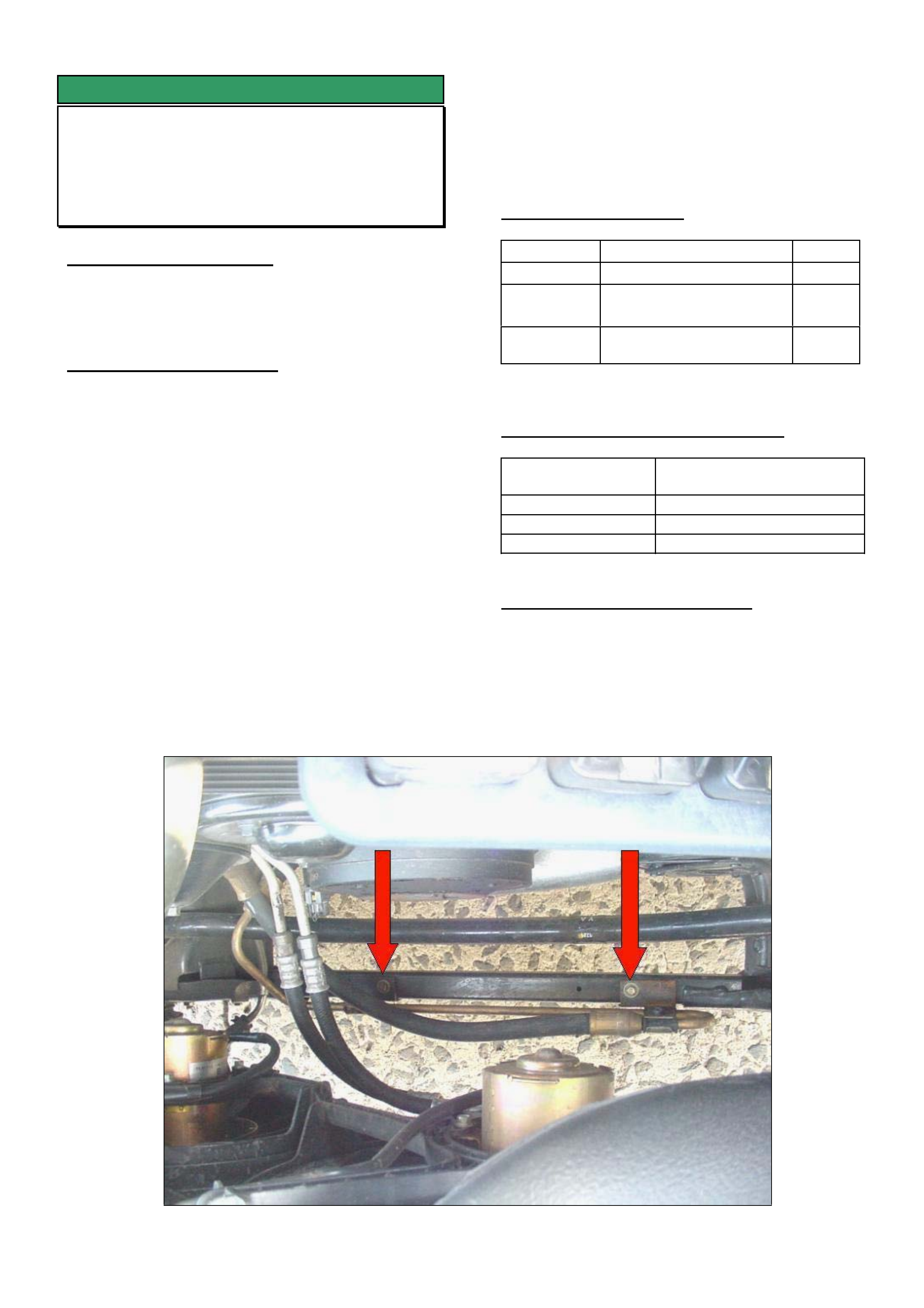
SUGGESTED CORRECTION
1. For vehicles with the above condition it is
recommended to adjust the bottom of the rear
bumper fascia rearwards by 10mm. This action is
intended to alter the angle of the sensors.
NOTE: Relocating the bottom of the fascia rearwards
by 10mm will require drilling new holes in the lower
attaching metal bracket for the 2 retainers.
2. Check the Rear Parking Aid system operation
again. If the system no longer detects and triggers off
the tow ball then adjustment is complete.
3. If the system continues to be triggered off the
tow ball, interchange the two inner sensors with the
two outer sensors and re evaluate system operation.
4. If the system continues to be triggered off the
tow ball perform the rear park aid diagnosis
procedure as shown in Passenger SIP.
Retainer
Retainer
PULL

HOLDEN SERVICE TECHLINE __________________________________________________________________APRIL, 2004
11
SERVICE FIX
DTC’s P0171 & P0174 Fuel system lean,
Banks 1 & 2
VY II, V2 III, with GEN III V8 and M/T
(GROUP 6C) TL0682-0403
PROBLEM DESCRIPTION
DTC’S P0171 and P0174 setting (banks 1 & 2 lean
indication). After conducting extensive diagnosis
including checking for low fuel pressure, fuel quality
and vacuum leaks, no fault can be found.
The cause of codes P0171 & P0174 setting when no
evidence of running lean can be found, is
oversensitive PCM software calibration.
PRODUCTION RECTIFICATION
Breakpoint information for the introduction of revised
PCM software calibration into vehicle production will
be advised in a future Techline.
SERVICE RECTIFICATION
Revised PCM software to rectify P0171 and P0174
setting unnecessarily was released on TIS 2000 CD
50.
HOLDEN SERVICE TECHLINE __________________________________________________________________APRIL, 2004
12
SERVICE FIX
Low Speed Steering Shudder
VY with V6 engine (non S/C)
(GROUP 9) TL0615-0403
PROBLEM DESCRIPTION
Some vehicles may experience a shudder felt
through the steering wheel, when very low speed or
stationary steering operation is performed.
SERVICE RECTIFICATION
Summary: Fit revised high pressure power steering
hose between pump and steering gear.
Procedure:
1. Remove power steering high pressure hose
between pump and steering gear.
2. Fit revised high pressure power steering hose
(p/n 92174786) between the pump and steering
gear. Use new seals at the pump and the
steering gear (p/n 08526398).
3. The new hose has extra length which is to be
routed across the front of the engine. Refer figure
1.
4. The two brackets that are integral to the new
hose are to be fixed to the front cross member
brace using screws (p/n 11069615) inserted into
existing holes as shown in figure 1 by arrows.
5. Top up power steering system and bleed as per
SIP procedure.
PARTS INFORMATION
Part No.: Description: Qty:
92174786 High Pressure Hose 1
11069615 Screw -Pressure power
steering hose
2
08526398 Seal – Pressure Pipe to
pump and steering gear
2
WARRANTY CLAIM INFORMATION
Description Power Steering Hose Kit
Installation
Labour Op. No. M000205
Time 0.5 hr
Failure Code 36/ M0036 vibrates
PRODUCTION RECTIFICATION
At the time of printing, the breakpoint for fitting
revised high pressure hoses to vehicles has not
been established. When it is established, this
techline will be updated on Holden Lionheart.
HOLDEN SERVICE TECHLINE __________________________________________________________________APRIL, 2004
13
SERVICE FIX
Steering Wheel Spokes - Satin Chrome
Finish Comes Off
V2, WK, VY
(GROUP 9) TL0655-0403
CONDITION
On some vehicles the satin chrome finish may come
away from the steering wheel spoke substrate
material.
CORRECTION in SERVICE
Summary: On complaint vehicles, replace faulty
spoke covers as per following procedure.
1. Remove steering wheel as per procedure in PV
SIP.
2. Detach rear cover from steering wheel.
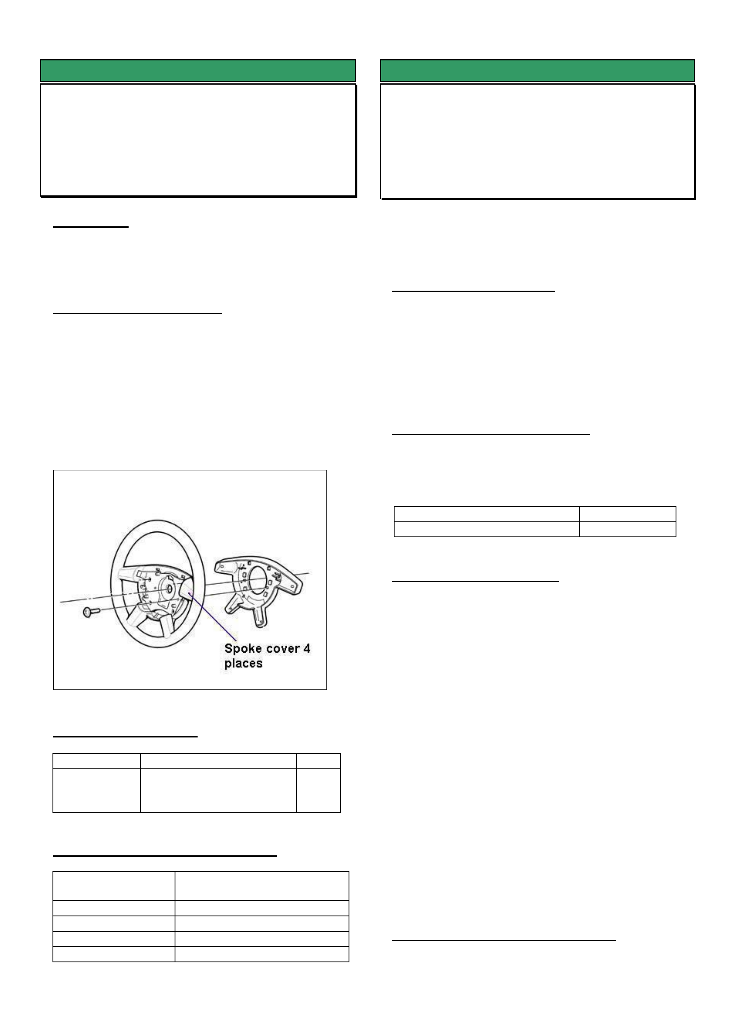
3. Remove four spoke covers by undoing attaching
screws from rear.
4. Install new spoke covers.
5. Reinstall all parts.
PARTS INFORMATION
Part No.: Description: Qty
92147964 Cover package steering
wheel spokes (contains
4 covers)
1
WARRANTY CLAIM INFORMATION
Description Replace steering wheel
spoke covers
Labour Op. No. C000514
Time 0.5 hr
Failure Code 23 - Finish comes off
Failure Code NOW C0023 – Finish comes off
SERVICE FIX
Blaupunkt Radio Losing Time or CD Will
Not Eject
VY / V2 II
(GROUP 12) REVISED TL0580A-0403
This techline supersedes the previous one
TL580-0311) in Issue 11, Nov. 2003. It is revised
by removing WK from the models affected.
Please correct all previous copies of TL0580-0311.
PROBLEM DESCRIPTION
Customers may complain of the clock in their
Blaupunkt radio losing time or that the CD will not
eject.
After investigation into the root cause, Blaupunkt has
made a software revision to rectify this condition.
PRODUCTION RECTIFICATION
Blaupunkt has implemented a software revision for all
radios introduced into production as of the following
break point.
ISOVIN: Build Date:
6G1YX54AX4L170039 8/09/03
SERVICE RECTIFICATION
If a customer presents a vehicle with the above
condition, request a replacement radio using the
standard change over request procedure which is
found in SIP “SPECIAL WARRANTY COMPONENT
REPLACEMENT REQUIREMENTS” section .
IMPORTANT: The Main Software Version number
must also be included on the request form.
Below is an example of the Identification Data screen
displayed on Tech 2 where this information can be
found.
Identifier 404
Part number 92118704
Production Date 60103
Main Software Version ????
Panel Software Version 1A22
Serial Number 804697
VIN Digit 1-10 6G1YK54A74
VIN Digit 11-17 L169008
WARRANTY CLAIM INFORMATION
Use Labour Times information in Warranty
Information section of current PV SIP CD

HOLDEN SERVICE TECHLINE __________________________________________________________________ MAY, 2004
DIAGNOSIS HINT
Tech 2 Communications with
ABS/ TC/ ESP
TS Convertible & SRi Turbo
(GROUP 5) TL0689-0404
TAS receive many calls where technicians are
experiencing difficulty when trying to communicate
with ABS on the vehicles listed above.
Technicians are selecting ABS/TC from the Chassis
menu on Tech 2 as they are unaware that ESP is
fitted standard to these vehicles. Tech 2 will continue
to display “waiting for data” until “abort” is chosen.
ESP should be selected from the Chassis menu. This
will allow Tech 2 communications for the
ABS/TC/ESP system including all data lists,
miscellaneous tests and diagnostic trouble codes.
HOLDEN SERVICE TECHLINE __________________________________________________________________ MAY, 2004
SERVICE FIX
ABS Light Comes On, DTC 71 Set
VY, V2, WK
(GROUP 5) TL0685-0404
CONDITION
Customer reports the ABS Instrument panel light
comes on.
Dealer diagnosis reveals DTC 71 “Control Module
Internal Fault” is being logged. Diagnostic checks as
per SIP lead to module replacement.
CAUSE
An abnormality with the electronics in the ABS control
module which only occurs at vehicle start up.
CORRECTION – Production
Revised ABS control modules have been fitted to
vehicles from:
ISOVIN: Built Date:
**********L239319 20/2/2004
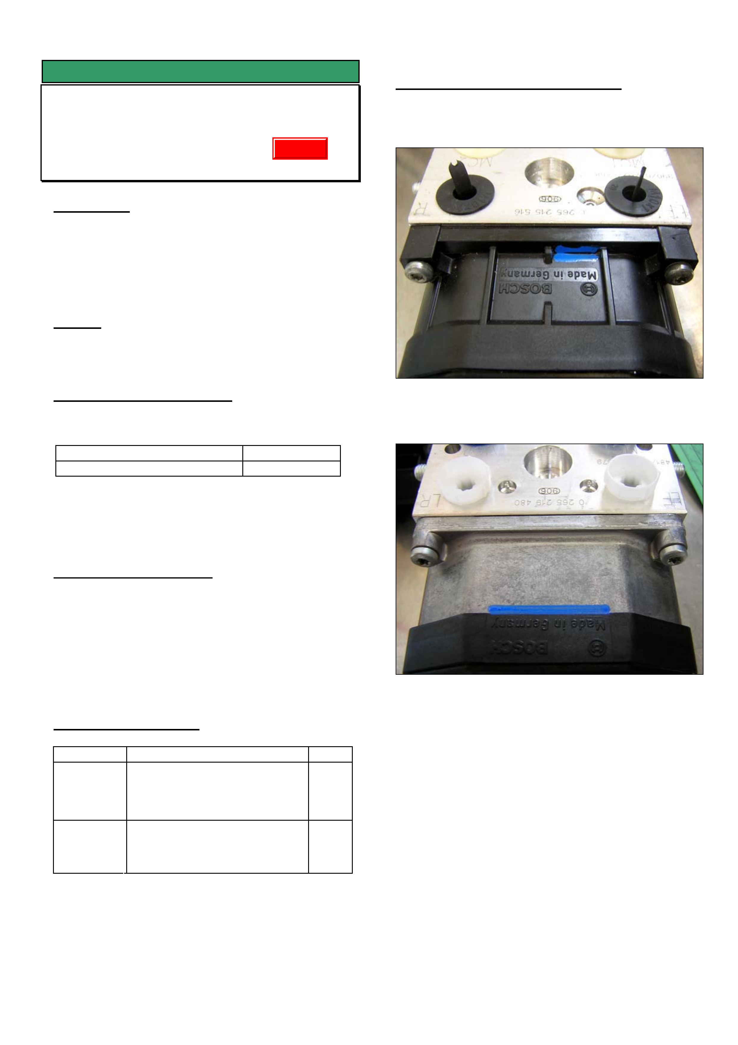
NOTE: Revised modules fitted in production and
supplied from HSPO are identified with blue paint as
shown in the attached photographs.
CORRECTION – Service
After verifying that vehicle has symptoms as
described above, fit a new ABS control module and
hydraulic modulator assembly.
This can only be obtained from HSPO after receiving
approval from BOSCH via the Prior Approval
program.
PARTS INFORMATION
Part No.: Description: Qty
92093868ABS control module &
hydraulic modulator assembly
(V6 & V8 without traction
control)
1
92093870ABS control module &
hydraulic modulator assembly
(V6 with traction control)
1
Attention Parts Managers!!
Any ABS control module & hydraulic modulator
assemblies prior to breakpoint (i.e units without blue
paint mark) should be returned to HSPO for credit via
the CRRM system.
WARRANTY CLAIM INFORMATION
Use Labour Times information in Warranty
Information section of current PV SIP CD
Figure 1. 92093868
Figure 2. 92093870
Update
HOLDEN SERVICE TECHLINE __________________________________________________________________ MAY, 2004
INFORMATION
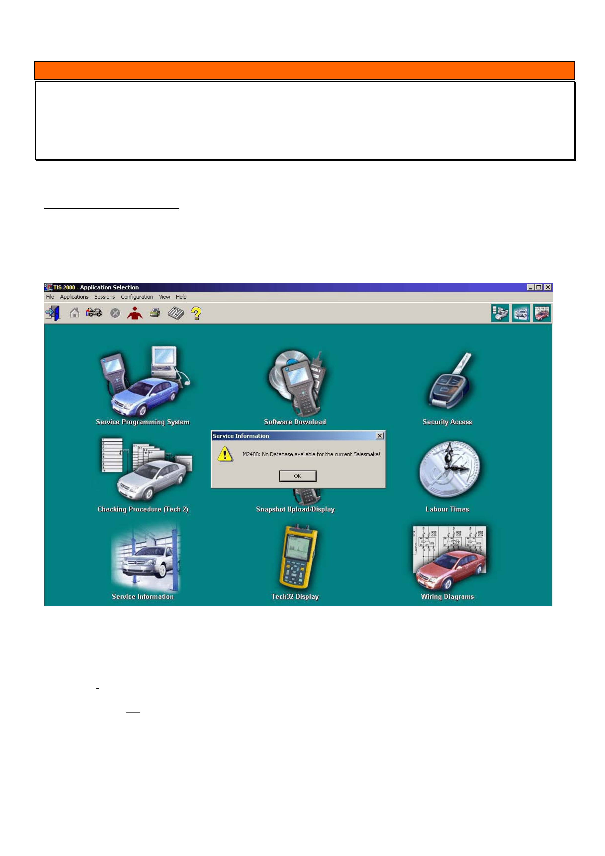
TIS 2000 error message when accessing Service Information or Security Access
TIS 2000
(GROUP OB) TL0690-0404
This techline is to be used in conjunction with Technicians guild article number 8 of 2003
PROBLEM DESCRIPTION
TIS 2000 displays error codes when user attempts to access some functions. Prior to seeking help from
TAS, it is recommended you perform the following checks.
When accessing Service Information the following screen may appear.
To overcome this problem, click the “ok” button in the message box. Click on the word “configuration” at the top of
the screen, select “options”. Starting from the left tab make sure the following selections are made.
Language: English (united states)
Country: Australia or New Zealand as applicable
Salesmake: Opel (unless doing Isuzu product then select Isuzu, do not select Holden for any product)
Dealership: Holden
WWW: Do not tick the enable java box
Click “ok”
After the settings have changed, a message box will appear advising that the salesmake settings have changed and
TIS must be restarted, click YES to this. Another message about closing open sessions will appear. If there are no
other open sessions click “YES”. Restart TIS and retry service information. If you continue to have problems with
service information a TAS nominated contact should contact TAS.
HOLDEN SERVICE TECHLINE __________________________________________________________________ MAY, 2004
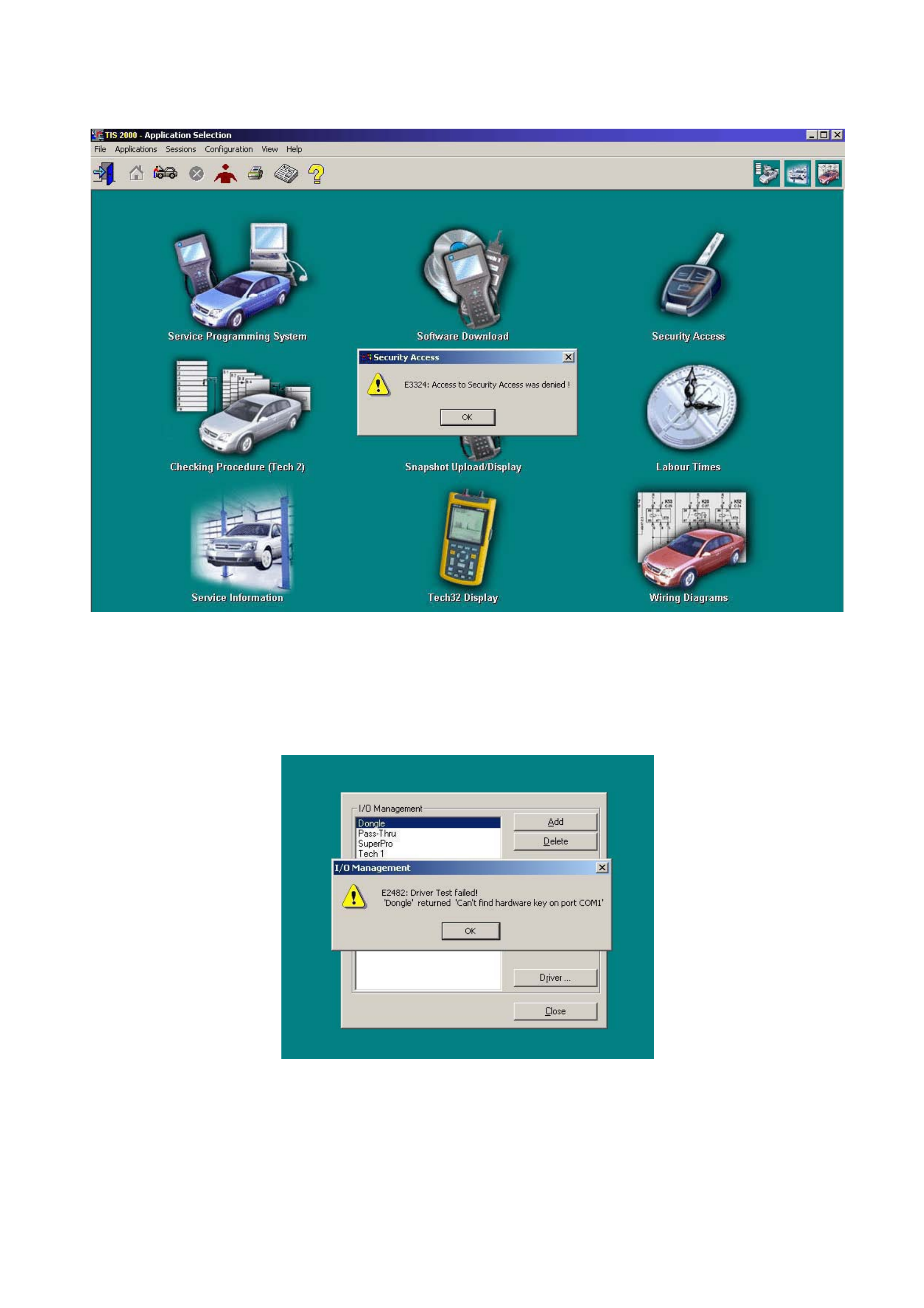
When accessing Security Access the following message may appear.
(Make sure your hardware key is installed prior to attempting to obtain Security Access).
.
Click the “ok” button in the message box and then click on the word “configuration” at the top of the screen.
Select “I/O management” and make sure “Dongle” is highlighted (unless you have the new super pro USB hardware
key in which case “super pro” will need to be highlighted). Press the “test” button on the right hand side. The
following message may appear.
Click “ok” in the message box and then press the “properties” button on the right hand side. A box displaying the
current com port that is selected will appear. Click on the black arrow on the right of the message box; this will
display the other com ports available. Select a different com port than the one displayed (not LPT1) and click ok.
Press the test button again. If more than 2 com ports available then this may have to be done again on all com ports
until it passes. When message appears saying “Driver test successful” click “ok” and close I/O management box.
Retry Security access.
If problems still occur a TAS nominated contact should contact TAS.

HOLDEN SERVICE TECHLINE __________________________________________________________________ MAY, 2004
INFORMATION
TIS 2000 Update And Uninstall Procedure
(GROUP 0B) TL0691-0404
TAS receive many calls where a TIS 2000 Update or
a new TIS 2000 Installation has failed. This techline
is to clarify the following procedures:
• Update TIS 2000
• Uninstall TIS 2000
• TIS 2000 Configuration Options
If your Dealership has a PC specialist, it would be an
advantage to utilise his/her expertise.
Update TIS 2000
To update TIS 2000 proceed as follows:
• Place TIS CD1 in your disc drive, wait a few
seconds and then click on the icon, which
opens TIS 2000. This will then see the disc as
an update and continue to upload. On
completion of the first, it will request that you
load the second disc. When the second disc
is inserted, click OK in the dialog box to begin
the upload.
• Both LCV TIS and Wiring Diagrams CD’s
should be treated as an Update.
Uninstall TIS 2000
To uninstall TIS 2000 proceed as follows:
• Remove any cd’s from all drives.
• Shut down and Restart your computer (PC).
• Click on the Start button (lwr left of screen).
• Move up to programs then across to TIS 2000
and again across to TIS 2000 Uninstall.
Select Uninstall from this menu.
• When the Uninstall is fully complete it should
advise if it was successful. If not, you will
need to run through the following procedures.
• Click on the Start button again and choose
Search or Find, moving over to Files or
Folders.
• Type cosids in the search field, and then
choose local hardrives in the look-in field.
Now select Search/Find now. This will
generate a search for the TIS 2000 main files.
(If any files are found it will be displayed in the
large box to the right, if not continue to next
step)
• Delete all files that have been found, by
selecting with your mouse and hitting the
delete button on your keyboard.
• Now click on the Start button again and scroll
up to Settings, then move across to Control
Panel. In this menu, double click on
Add/Remove Programs and look for the
following items:
JAVA 2 RUNTIME ENVIRONMENT STD EDITION
and
JAVA SERVLET DEVELOPMENT KIT.
• If they are available, select one at a time then
hit the Change/Remove button for each.
Close this window.
• It is now very important to restart your
computer.
TIS 2000 CONFIGURATION OPTIONS
When attempting a complete TIS 2000 install, place
CD1 in the drive and this should now begin the
installation. It will request the second CD when
required.
Follow all prompts until the installation is complete.
NOTE: it is very important that you select the following
configuration when prompted:
• Language – English
• Country – Australia/New Zealand (whichever
is applicable)
• Salesmake – OPEL
• Dealership – HOLDEN
• WWW – not checked (ticked)
You will also need to select which COM port you
would like your TECH 2 and Hardware Key to
communicate with. You must ensure these are both
the same. E.g.; COM1 or COM2.
HOLDEN SERVICE TECHLINE __________________________________________________________________ MAY, 2004
INFORMATION
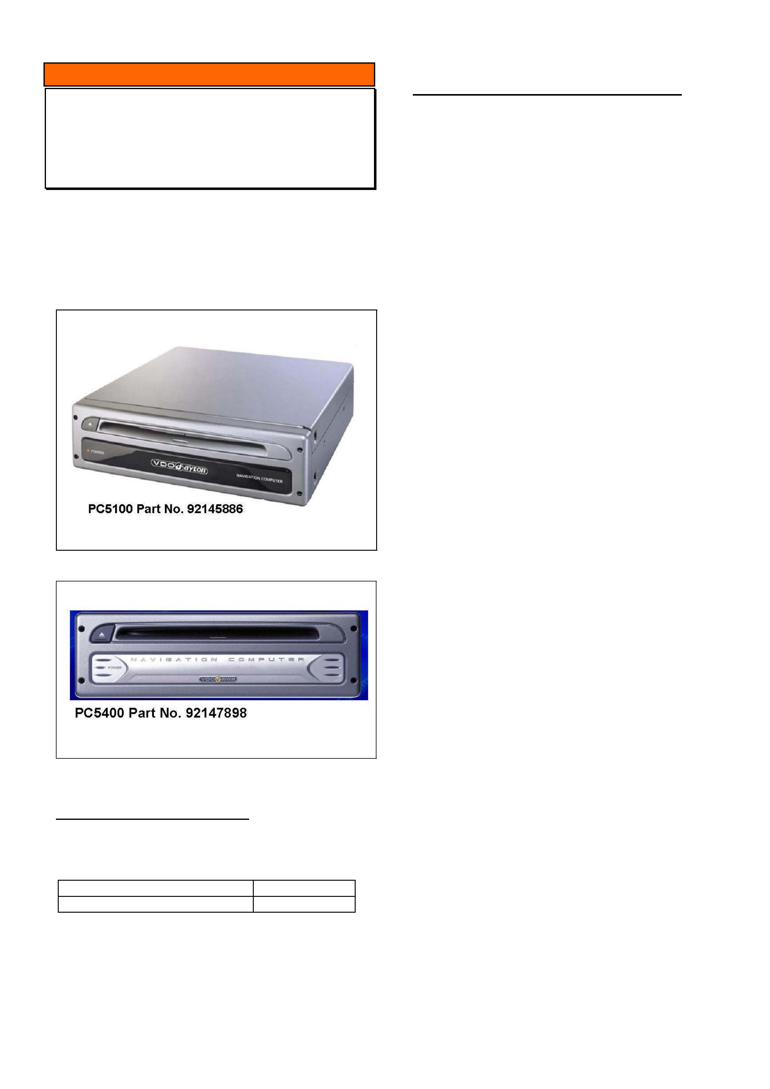
Sat Nav Computer Upgrade
All with HBD SATNAV
(GROUP 12) TL0658-0404
The PC5100 Navigation Computer Part No. 92145886
has been superseded by an upgraded PC5400
Navigation Computer Part No. 92147898.
The PC5100 Navigation Computer Part No. 92145886
is no longer available.
PRODUCTION BREAKPOINT
The improved PC5400 Navigation Computer
92147898 has been fitted to vehicles from:
ISOVIN: Built Date:
6G1YK52A84L226898 23/1/2004
SERVICE REPLACEMENT PROCEDURE
If a vehicle with a PC5100 Navigation Computer
(92145886) ever requires replacement with a PC5400
Navigation Computer (92147898) the following
additional parts are required for correct operation:
• Patch harness Part No. 92147901 (includes zero
ohm link).
• Disc - Navigation Data (Map) Part No. 92211882.
The patch harness is installed in line between the
Navigation Computer and the vehicle wiring harness.
Installation procedure:
1. Disconnect vehicle battery.
2. Remove the vehicle wiring harness connector
from the back of the Navigation Computer located
in the boot.
3. Replace the plug-in resistor in the vehicle wiring
harness with the zero ohm links.
4. Remove the Navigation Computer from the cradle
using the removal tools.
5. Plug the patch harness 92147901 into the vehicle
wiring harness.
6. Insert the patch harness connectors into the back
of the newly installed Navigation Computer.
7. Install the PC5400 Navigation Computer Part No.
92147898 into the Cradle.
8. Reconnect vehicle battery.
9. Follow installation instructions as supplied with
the Disc - Navigation Data (Map) Part No.
92211882.
10. NOTE: When inserting a C-IQ Map disc (this is
the Map disc p/n 92211882 compatible with the
PC5400 Part No. 92147898) into a system for the
first time, a code to activate the map data will be
required. This code can be obtained from
Siemens VDO direct on 1800 335 282.
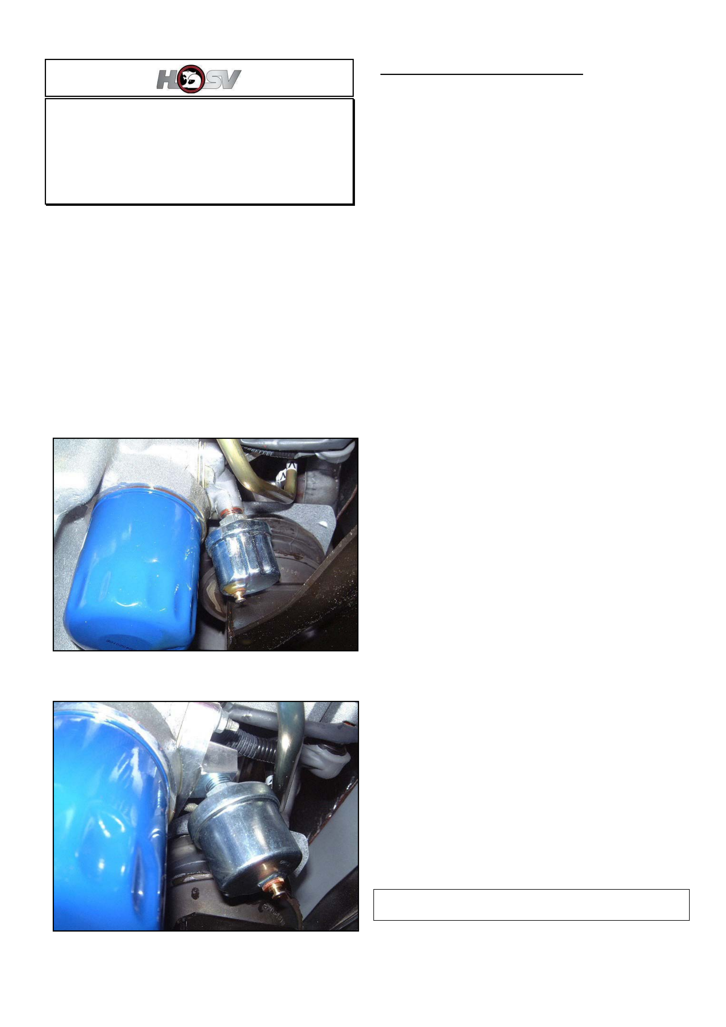
HOLDEN SERVICE TECHLINE __________________________________________________________________ MAY, 2004
Oil Sender Adaptor Fouls On HSPO Oil
Filters
HSV vehicles with optional gauges
(GROUP 6A) TL0598A-0404
This techline supersedes previous techline TL0598-
0311. All copies of that techline should be marked
“superseded”.
Oil sender adaptor part No 06G - 020601 as fitted to
HSV vehicles with optional gauges does not provide
enough clearance for some types of oil filters fitted in
service. Refer Figure 1.
New adaptor part No 06G – 030601 provides more
clearance (refer Figure 2). On vehicles with a built
date prior to 6 Feb. 2003, sender part No. 12J-020608
will also be required. Both parts are available from
your HSV State Distributor.
Figure 1. Old Adaptor
Figure 2. New Adaptor
LIST OF HSV DISTRIBUTORS
SUTTONS PARTS
22 CARTER ST, LIDCOMBE, N.S.W., 2141
PH: 02 9648 3688
FAX: 02 96471483
Email: [email protected]
HSV Specialist. Miss Kerri Wilkens
MD/General Manager Mr Darrall Elson
PRESTON MOTORS
1551 SYDNEY RD, CAMPBELLFIELD, VICTORIA
3061
PH: 03 9359 3999
FAX: 03 9357 3350
Email: [email protected]
HSV Specialist. Mr. Shaun Lacey
MD/General Manager Robin Mc Clean
ZUPPS PARTS
1032 BEAUDESERT RD, COOPERS PLAINS, QLD
4108
PH: 07 3259 5051
FAX: 07 3875 1773
Email: [email protected]
HSV Specialist.Mr Richard Morris
MD/General Manager Mr Robert Lemon
AMCAP BBK
171 WELSHPOOL RD, WELSHPOOL, W.A. 6106
PH: 08 9351 6666
FAX: 08 9351 6636
Email: [email protected]
HSV Specialist. Mr Noel Learson
MD/General Manager Mr Peter Hewett
METRO HOLDEN
THEBARTON, 1 PORT RD, S.A. 5031
PH: 08 8354 0555
FAX: 08 8352 6678
Email: [email protected]
HSV Specialist. Mr Roger Kramer
MD/General Manager Mr Trevor Olsen
The above information has been supplied by HSV for
distribution to all Holden dealers……………………

HOLDEN SERVICE TECHLINE __________________________________________________________________ MAY, 2004
SERVICE FIX
Antenna Extends and Radio Turns on by
Itself
VY / WK / V2 Series II & III
(GROUP 12) TL445A-0404
This Techline supercedes TL445-0303 published in
Issue 3, March 2003. This Techline now includes
information on a replacement antenna connector.
PROBLEM DESCRIPTION
There have been several reports where customer
advises that they have returned to their vehicle to find
the antenna is up and the radio on.
In some situations the customer will also find their
wipers going if they have switched the ignition off
while they are running.
This problem only occurs on vehicles, which have a
low or mid series BCM and also have an electric
antenna.
The cause of this problem is water entry into the two
pin connector at the electric antenna.
SERVICE RECTIFICATION
Summary: Remove water from antenna connector. If
damaged or corroded replace connector.
1. Remove all water from the antenna connector.
2. Confirm that all seals are correctly located around
each wire in the connector and between the
mating surfaces of the connector.
3. Apply Nyogel grease to the connector cavity and
then re-assemble the connector.
4. Ensure that the connector positively engages.
Antenna Connector Replacement
If the antenna connector is damaged or corroded a
replacement connector and lead is available from
HSPO (refer parts information).
When replacing the antenna connector ensure that
the wires are joined using the methods outlined in
Passenger vehicle SIP.
MY2003 VY & V2 II Including Ute / Wiring Diagrams /
Section 12P-Wiring Diagrams / 5. Wiring Repair
Procedures / Performing Wiring Harness Repairs.
Note: Once the wires are joined, ensure they are
appropriately insulated using electrical tape or heat
shrink tubing.
Ensure the wires are connected to the correct location
(the replacement connector wires are both black).
PARTS INFORMATION
Part No.: Description: Qty:
92146329 Nye Nyogel 760G
Grease – 30cc syringe
1
92147807 Connector & Lead 1
WARRANTY CLAIM INFORMATION
Description Dry water out of antenna
connector
Labour Op. No. N000426
Time 0.4 hr
Failure Code N0115
Description Connector Replacement
Labour Op. No. N000460
Time 0.5 hr
Failure Code N0100

HOLDEN SERVICE TECHLINE __________________________________________________________________ MAY, 2004
INFORMATION
VIN – Vehicle Identification Number
ALL
(GROUP 0B) TL0692-0404
It has come to our attention that some technicians
have difficulty interpreting the 17 digit Vehicle
Identification Number (VIN). This number is also
known as ISOVIN which stands for “International
Standards Organisation Vehicle Identification
Number”.
It is important for technicians to understand the
makeup of VIN as many Holden systems/processes
may require the model year, body style and engine
type from the VIN.
To refer to the makeup of VIN refer to Passenger
Vehicle SIP as follows.
VT, VX, V2, VU, WH – SIP Section 0A, 8.5
VY, V2II, WK – SIP Section 0A, 9.5
The Vehicle Owners Handbook always has an
explanation of VIN in Section 8.
NOTE: The model year for vehicle manufacturing
does not change from January 1 each year, but
usually in September/October in the calendar year
before.
For example, a vehicle built in October 2003 will have
a ‘4’ (2004 model year) listed as the tenth digit in the
VIN.
SERVICE FIX
Whistle from HVAC case
VY II, V2 II, WK
(GROUP 2) TL0641-0404
CONDITION
A “whistle” noise from the HVAC that increases as the
blower fan speed is increased.
CAUSE
Distortion of the evaporator upper cover to the HVAC
case. This distortion causes a gap of between 1 and
2 mm between the HVAC case and the evaporator
cover.
CORRECTION in PRODUCTION
HVAC assemblies with two extra screws attaching the
evaporator upper cover to the HVAC case have been
fitted to vehicles from:
ISOVIN: Built Date:
6G1KY54F74L233256 29/01/04
CORRECTION in SERVICE
Remove the IP pad and HVAC assembly and add 2
additional screws to evaporator cover as per the
procedure on following page.
NOTE: Zone approval must be obtained prior to
proceeding with this work.
PARTS INFORMATION
Part No.: Description: Qty:
92147967 Screw (pack of 10) 1
Butyl Mastic sealer can be obtained from most
hardware retailers.
WARRANTY CLAIM INFORMATION
NOTE: Zone approval is required to claim for this
work.
Description Add 2 extra screws to
HVAC evaporator cover.
Labour Op. No. D000345
Time 4.3 hr
Failure Code D0042 Leaks
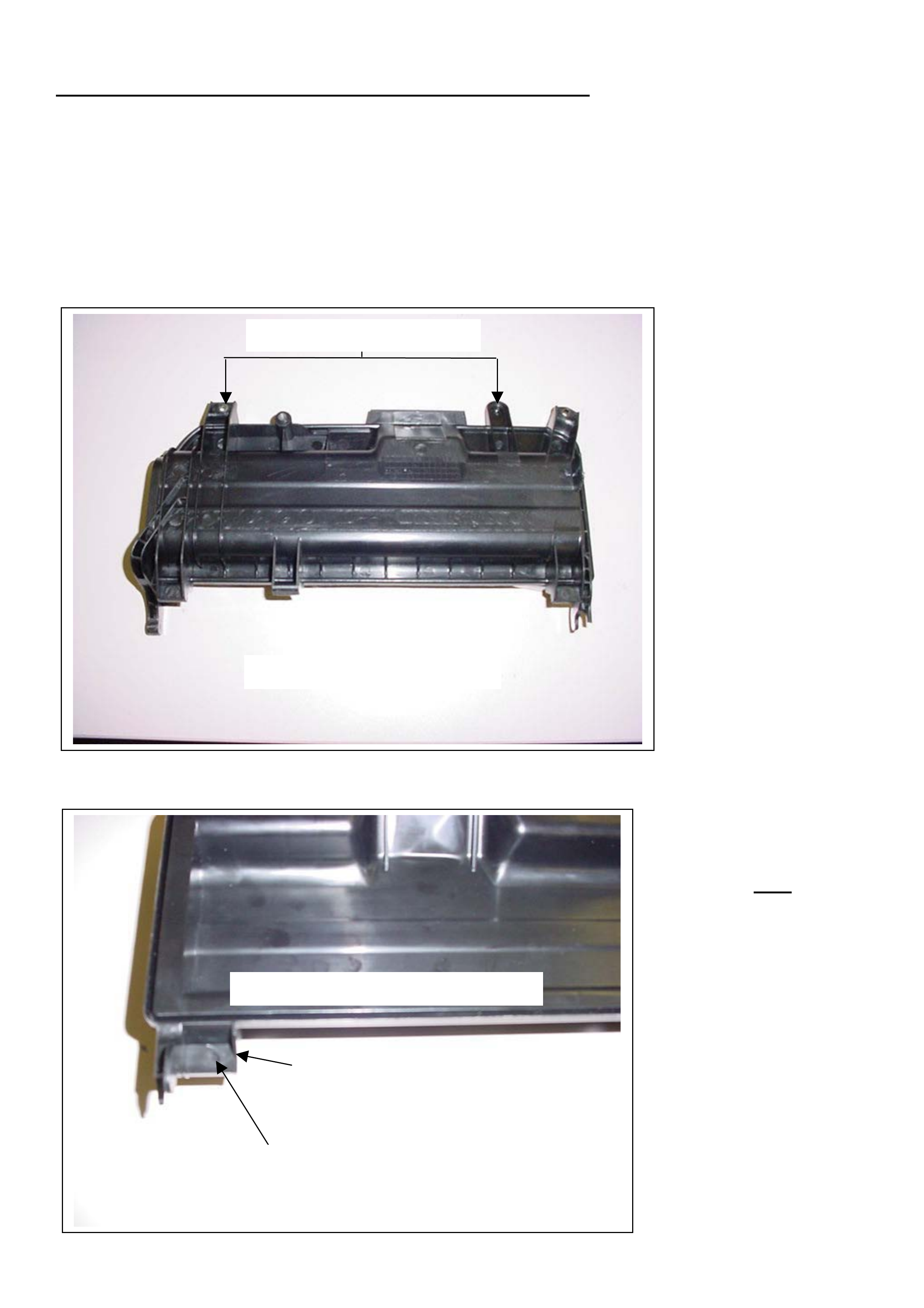
HOLDEN SERVICE TECHLINE __________________________________________________________________ MAY, 2004
Instruction For Adding 2 Extra Screws To Evaporator Cover.
NOTE: Zone approval must be obtained prior to proceeding with this work.
1 Recover the refrigerant.
2 Remove the vehicle instrument panel pad
3 Remove the HVAC assembly.
4 Detach the ECC aspirator tube (if fitted) and the Two (2) self tapping screws retaining the upper
cover to the HVAC.
5 Remove the evaporator upper cover.
6. Drill a 5mm hole
through the plastic
tabs of the upper
cover. Note: on
the underside of
this cover the tabs
already have a
recess to guide the
drilling position.
(refer to diagram)
EVAPORATOR UPPER COVER
2 SELF TAPPING SCREWS
RECESS IN TAB (BOTH SIDES OF
COVER
)
–
DRILL 5MM HOLE
UNDERSIDE OF EVAPORATOR COVER
TAB
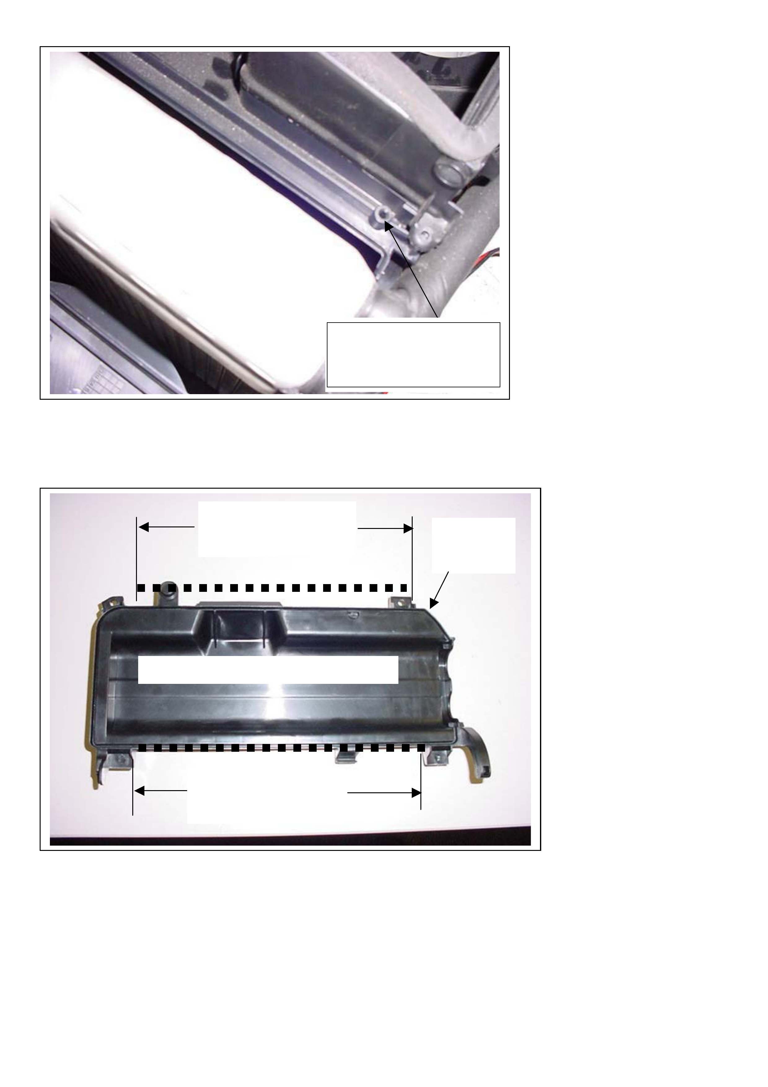
HOLDEN SERVICE TECHLINE __________________________________________________________________ MAY, 2004
8.
A
pply Butyl mastic to
the groove area of
the evaporator upper
cover as shown in
the diagram.
9. Two (2) extra self
tapping screws are
required to reinstall
the evaporator upper
cover. These screws
are available
through HSPO p/n.
92147967 (packet of
10)
10. Refit the evaporator
upper cover using
the Four (4) self
tapping screws
ensuring that the
tongue and grooves
joints are correctly
joined together.
11. Reassemble all
removed
components in their
reverse order.
7. When the upper
cover is refitted the
self tappers used in
the new positions will
be inserted into the
screw bosses shown
in diagram.
BOSS IN HVAC CASE,
AIR ON SIDE (2 PLACES)
HOLES FOR SELF
TAPPING SCREWS
A
PPLY BUTYL MASTIC
INTO THE GROOVE IN
THIS AREA
UNDERSIDE OF EVAPORATOR COVER
GROOVE
AROUND
COVER
A
PPLY BUTYL MASTIC
INTO THE GROOVE IN
THIS AREA

HOLDEN SERVICE TECHLINE __________________________________________________________________ MAY, 2004
SERVICE FIX
Park Brake Shoe Scrape
VT, VX, VY, VU, V2, WH, WK
(GROUP 5) TL0452A-0404
This techline supercedes TL452-0304 published in
Issue 4, 2003. The rectification procedure now
involves fitting a spring to centralise the park brake
shoe.
PROBLEM DESCRIPTION
Some customers may complain of an intermittent
cyclic scraping noise from the rear of vehicle while
driving. Sometimes the noise appears to go away
after re-applying park brake lever.
The above condition is caused by the park brake
shoe front lining contacting the drum (in brake disc)
without the park brake being applied.
PRODUCTION RECTIFICATION
A spring, to centralise the park brake shoe in the
drum, is scheduled to be added to vehicles in June.
When this happens, the vehicle breakpoint details
will be published in the Breakpoint Summary.
SERVICE RECTIFICATION
Summary: Fit centralising spring to park brake shoe
as per following procedure.
Refer to Passenger SIP for any procedures not
specified.
1. Raise and support the vehicle. Ensure the park
brake lever is fully released.
2. Remove the rear wheel and brake caliper.
3. Mark the brake disc and hub prior to disassembly
to ensure same fitment position on re-assembly.
(Do not use excessive force to remove the disc as
it may be catching on the shoes. Back off the
shoe adjusting nut, if required, with a screwdriver
through the disc service hole).
4. Remove the park brake shoe as per SIP
procedure.
5. Spray clean the parkbrake thoroughly with
Brākleen or equivalent product.
6. Remove the upper rear mounting bolt. (Refer Fig. 1)
7. Install the spring bracket, and re-fit the upper
mounting bolt. Tighten to 75Nm. (Refer to Fig. 2 )
8. Drill a 4mm hole in park brake shoe outer flange
using attached template as a guide.
NOTE: Only one hole is required per shoe as
shown in Figure 3.
9. Carefully apply a thin film of Molybedenum
Disulphide grease (Shell RD5 or equivalent) to all
shoe contact points (refer Fig 1). Ensure that
grease does not contaminate the shoe brake lining
surfaces
10. Re install park brake shoe.
11. Install the new centralising spring as shown in
Figure 2. The spring should provide a small
amount of tension on the shoe. It should not sit
loose.
12. Clean brake disc with Brākleen or equivalent.
13. Set the shoe diameter to between 189.5 and 189.7
mm across the mid-point of the linings using the
adjuster nut. Do not use the cable at the park
brake lever to make this adjustment.
14. Refit brake disc in its original position according to
the marks made earlier.
15. Re-fit caliper and wheel.
16. With vehicle on ground, ensure correct operation
of park brake. Adjust cable if necessary as per
procedure in SIP.
PARTS INFORMATION
Part No.: Description: Qty
9214781
3
Park brake shoe scrape kit
(includes 2 brackets and 2
springs)
1
WARRANTY CLAIM INFORMATION
Description Install Park Brake Shoe
Spring kit – both sides
Labour Op. No. H000260
Time 1.2 hr
Failure Code H0040 noisy
Update
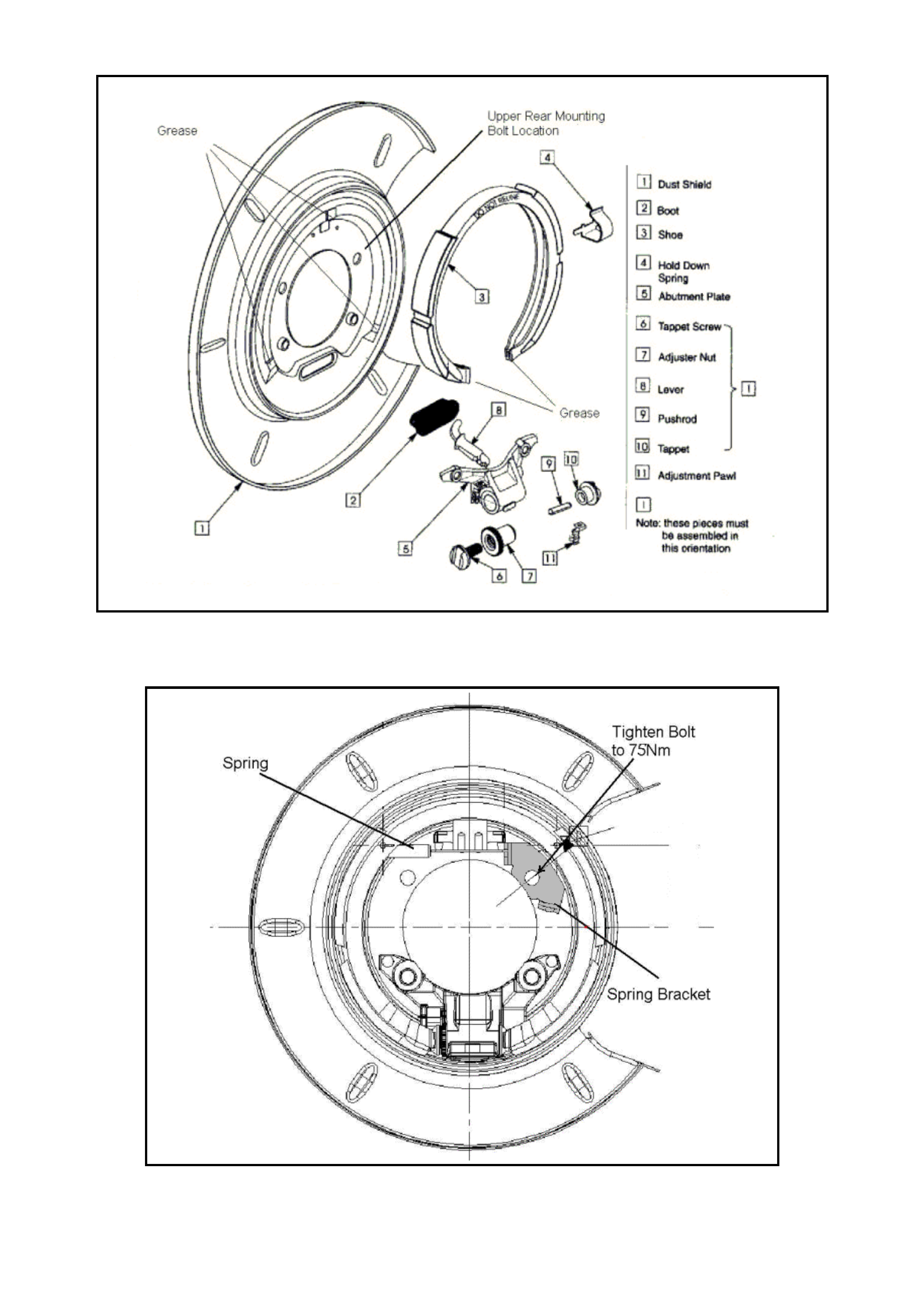
HOLDEN SERVICE TECHLINE __________________________________________________________________ MAY, 2004
Fig 1. Shows Left Hand Side Park Brake Components
Figure 2. Shows installation of centralising spring & bracket – Left Hand Side of vehicle.
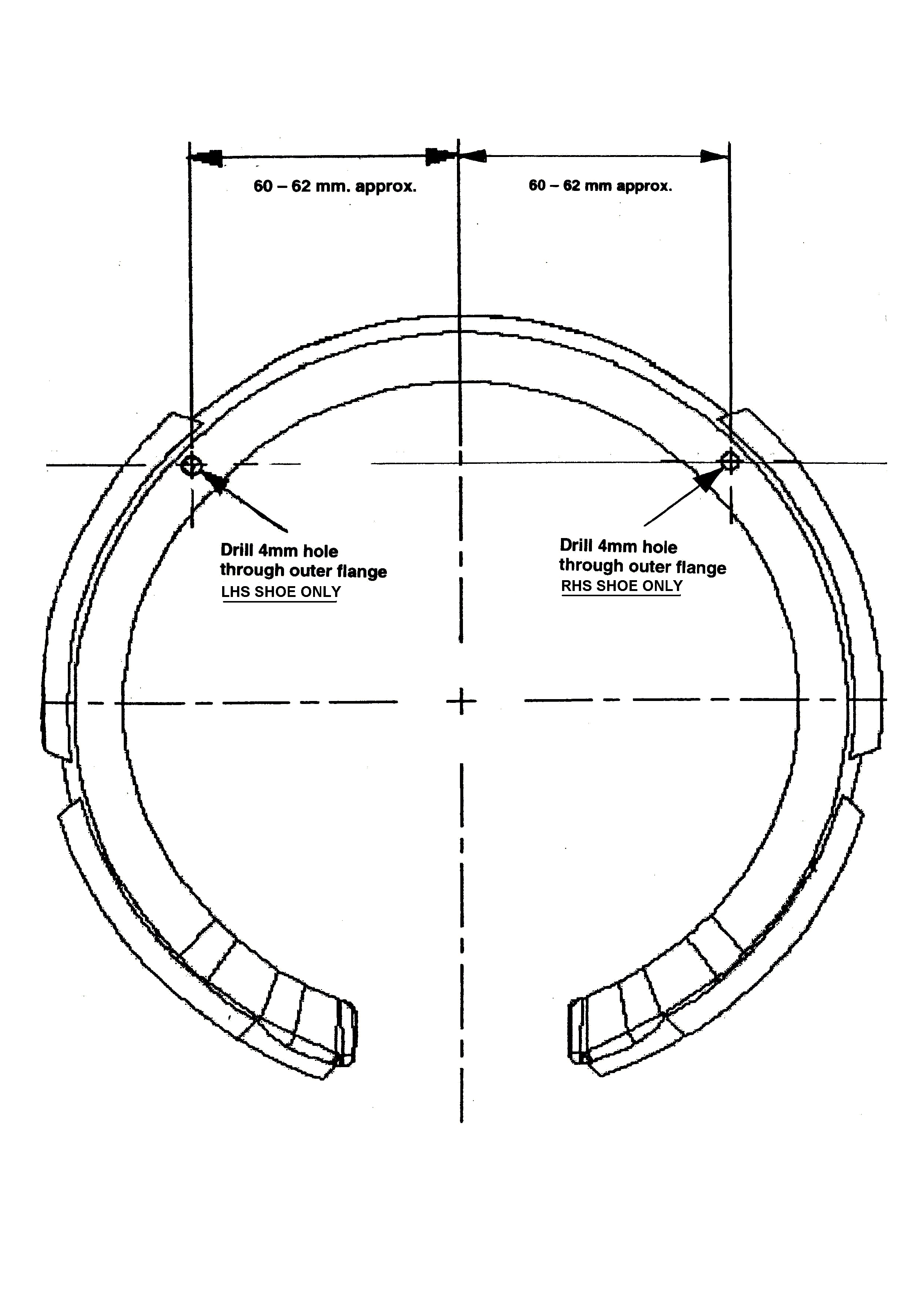
HOLDEN SERVICE TECHLINE __________________________________________________________________ MAY, 2004
Figure 3. Template for drilling holes in shoe (FULL SIZE)
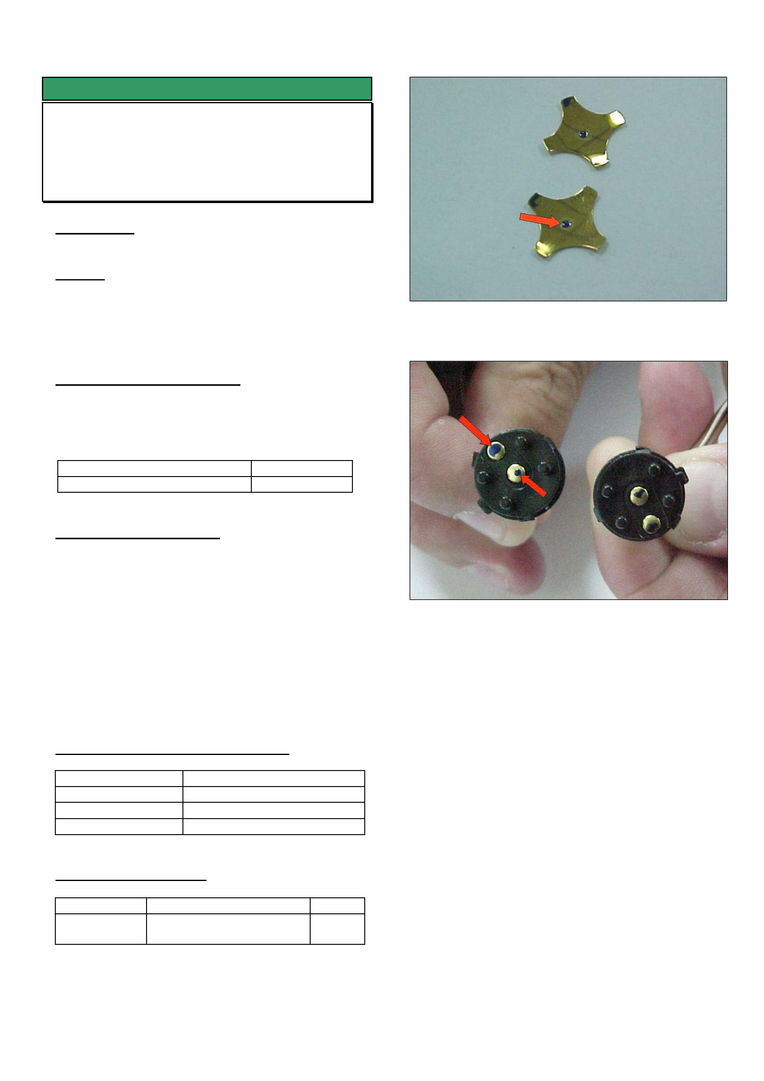
HOLDEN SERVICE TECHLINE __________________________________________________________________ MAY, 2004
SERVICE FIX
Horn Switch Contacts Corroded
XC Barina Sri (leather steering wheel)
(GROUP 12) TL0695-0404
CONDITION
Corrosion build-up on horn switch contacts.
CAUSE
A chemical reaction, between the copper in the switch
contacts and a polyurethane additive contained in
leather steering wheels, occurring in a high humidity
atmosphere.
CORRECTION – Production
Steering wheels manufactured with revised materials
and production processes to eliminate horn contact
corrosion have been fitted to vehicles from:
ISOVIN: Built Date:
W0L0XCF6844321975 19/04/04
CORRECTION – Service
Summary: Clean the horn switch contacts as per
following procedure.
Refer to TIS CD for any procedures not specified.
1. Remove switches/wiring harness from steering
wheel.
2. Disassemble switches to access contacts as
shown in Figures 1 and 2.
3. Wipe corrosion from contacts with a clean cloth.
4. Reassemble switches.
5. Reinstall switches into steering wheel.
WARRANTY CLAIM INFORMATION
Description Whatever Asm - Replace
Labour Op. No. N000466
Time 0.4 hr
Failure Code N00100 terminal corroded
PARTS INFORMATION
Part No.: Description: Qty:
09196058 Buttons – Horn, with
harness
1
Figure 1 Shows corrosion buildup.
Figure 2. Corrosion buildup on switch contacts.
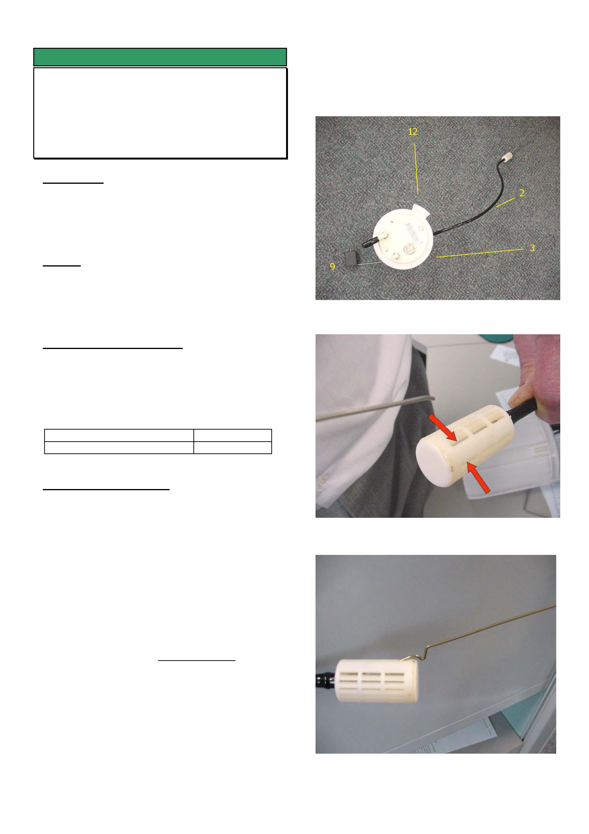
HOLDEN SERVICE TECHLINE __________________________________________________________________JUNE, 2004
5
SERVICE FIX
Fuel Gauge Problems Due To Auxiliary
Pickup Pipe Mislocated Inside Tank
VY Regular Cab / Crewman & Cross 8
(GROUP 8) TL0672-0405
CONDITION
Customers may report one of the following conditions:
• They can only get 35 to 40 litres of fuel in fuel
tank when fuel gauge shows Empty.
• Fuel gauge reads Empty after filling tank.
CAUSE
Auxiliary pickup pipe becomes dislodged from its
normal location in the tank and in some instances
may rest on top of the float arm.
CORRECTION - Production
A stiffening wire inserted into the MRA auxiliary
pickup pipe is scheduled to be added to vehicles in
early June. When available, vehicle breakpoint
details will be added to this techline on Holden
Lionheart.(on-line)
ISOVIN: Built Date:
TBA TBA
CORRECTION – Service
Summary. Remove MRA and install wire into auxiliary
pickup pipe as follows.
1. Remove the MRA from fuel tank as per SIP
procedure.
2. Place MRA on a flat bench and position the
components as shown in Figure 1. With the float
arm in the 9 o’clock position locate the auxiliary
pipe in the 2 o’clock position by twisting hose on
the MRA fitting. (use pliers if necessary).
3. Take stainless steel wire and insert the end
without the loop into the plastic filter through
either of the two slots on the upper side as shown
by the arrows in Figure 2.
4. Push the wire into the pickup pipe until the
locating notch touches the end of the filter as
shown in Figure 3.
5. Lift the notch up over the end of the filter so that it
locks into the filter as shown in Figure 4.
6. With the MRA sitting flat on the bench ensure that
the plastic filter sits parallel to the bench as
shown in Figure 4.
7. Reinstall MRA into the fuel tank taking care to
ensure that the auxiliary pickup pipe is sitting in
the secondary part of the fuel tank.
Figure 1. Layout of MRA prior to inserting wire.
Figure 2 Insert wire into either of the slots shown
Figure 3. Shows locating notch just prior to inserting
into the filter
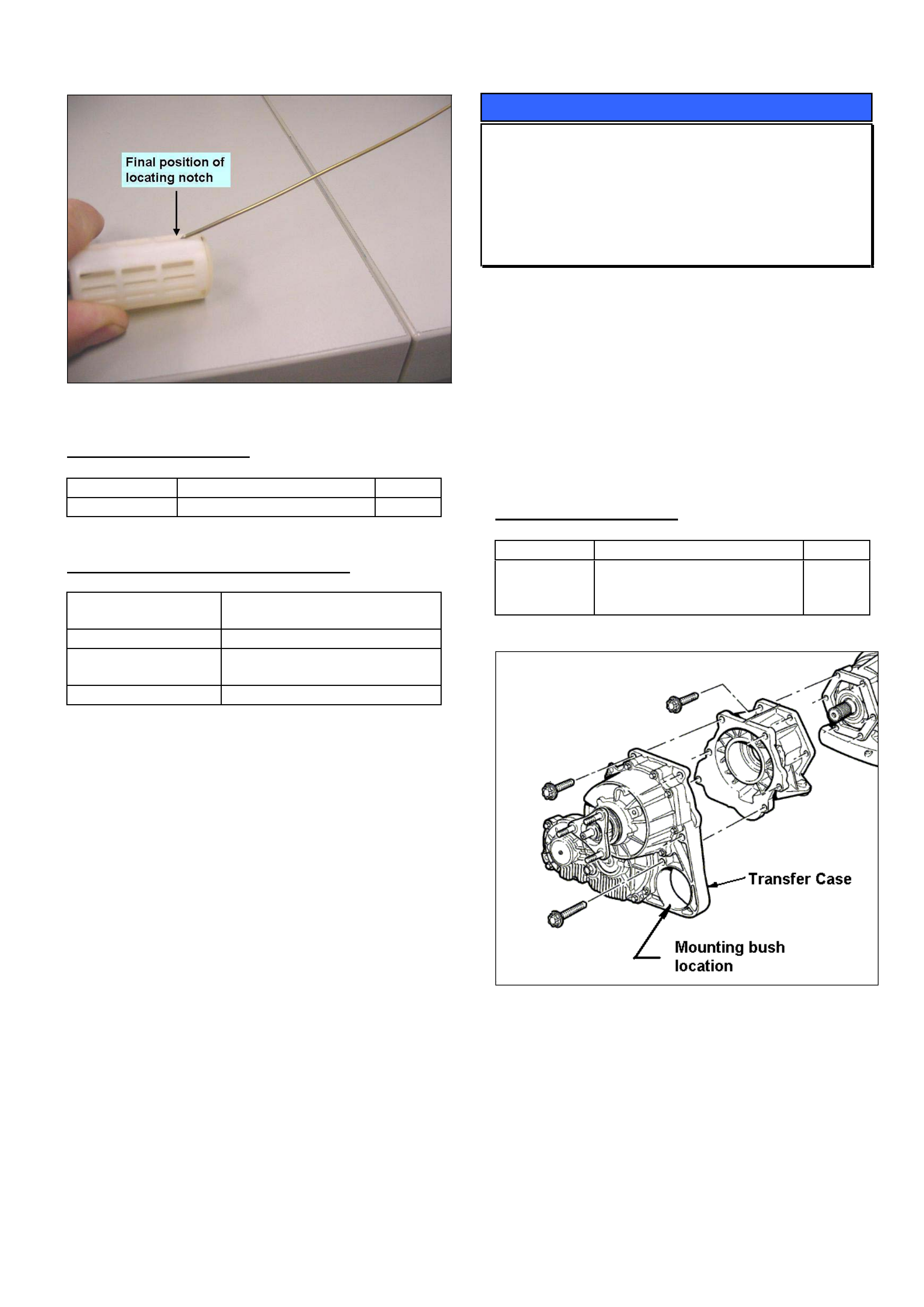
HOLDEN SERVICE TECHLINE __________________________________________________________________JUNE, 2004
6
Figure 4. Shows final position of locating notch.
PARTS INFORMATION
Part No.: Description: Qty:
92148344 Wire 1
WARRANTY CLAIM INFORMATION
Description Install wire into MRA
auxiliary pickup pipe
Labour Op. No. L000242
Time 0.9 hr – Regular cab
1.1 hr – Crew cab
Failure Code L0057 Registers incorrectly
SERVICE PROCEDURE HINT
Transfer Case Mounting Bush
Replacement
VY AWD Adventra & Cross 8
(GROUP 3) TL0704-0405
Whenever ordering a replacement transfer case from
spare parts, please note that it does not come with
the mounting bush 92114780. If required, this bush
will need to be ordered separately.
NOTE: If the existing mounting bush is still
serviceable you will need special tool DT- 47597 to
remove it from the old transfer case. This tool is
available from SPX.
PARTS INFORMATION
Part No.: Description: Qty:
92114780 Mount Assembly –
Transmission & Transfer
case
1
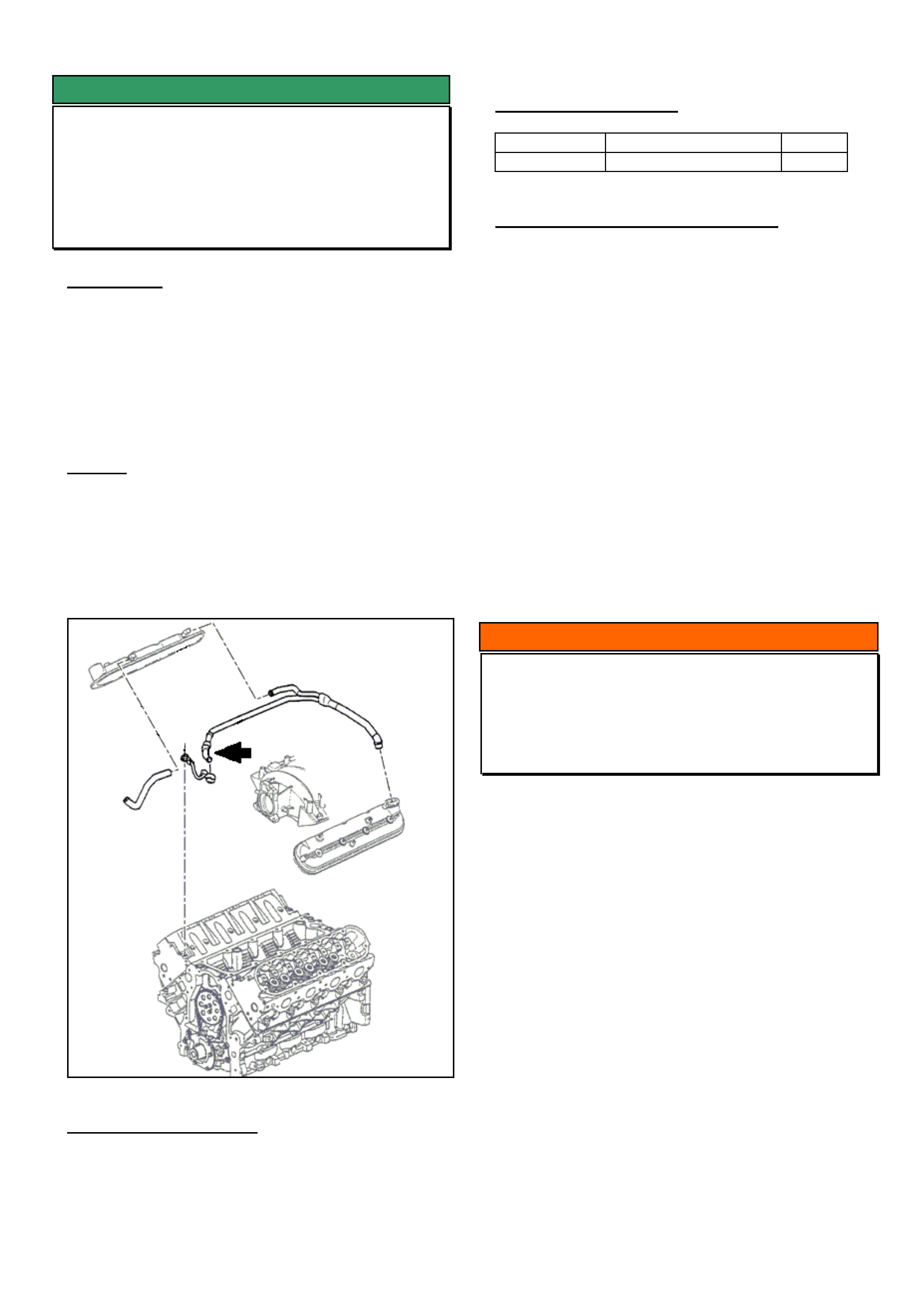
HOLDEN SERVICE TECHLINE __________________________________________________________________JUNE, 2004
7
SERVICE FIX
Gen III V8 - PCV Valve Pipe Material Revised
VT, VX, VY Series I, V2 up to 3L959133 ,
WH, WK up to 4L162085
(GROUP 6A) TL0622-0405
CONDITION
Some vehicles may experience the following
symptoms;
• Engine idles roughly,
• High pitch hissing noise
• Engine light on
• The following DTCs may set: P0131, P0151,
P0171, P0174.
CAUSE
Failure of the PCV valve pipe at the elbow as shown
by arrow in following diagram.
NOTE: WK and VY Series II vehicles are not affected
by this condition as they have a different PCV system.
CORRECTION - Service
Summary: Replace PCV valve pipe assembly, clear
DTCs with Tech2 and reset fuel trim cells.
NOTE: New PCV valve pipe assemblies from HSPO
are made from a revised material to prevent the
above failure condition.
PARTS INFORMATION
Part No.: Description: Qty:
12590632 Pipe – PCV valve 1
WARRANTY CLAIM INFORMATION
Use Labour Times information in Warranty
Information section of current PV SIP CD
INFORMATION
Tech 1 Dealer Cartridge
VR - VS
(GROUP OB) TL0714-0405
In order to obtain a Tech 1 Dealer cartridge with
security function, Dealers are required to fax a
request with their Dealer letterhead to the publications
department with details of the cartridge they require.
The fax number is listed below.
Fax: 03 9647 2525
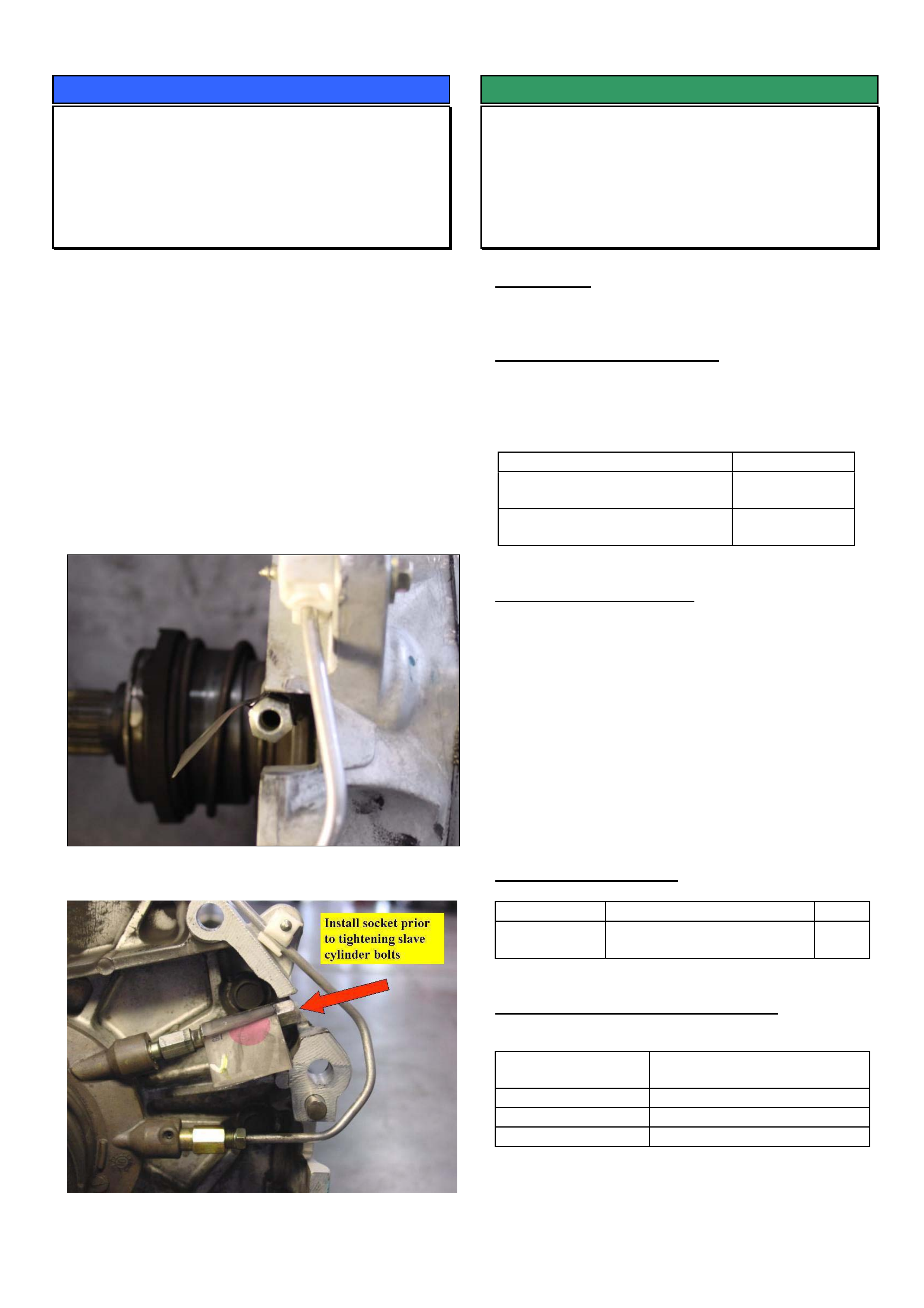
HOLDEN SERVICE TECHLINE __________________________________________________________________JUNE, 2004
8
SERVICE PROCEDURE HINT
Clutch Slave Cylinder Bleeder Alignment
All with Gen III V8 and Manual
Transmission
(GROUP 7A) TL0705-0405
Whenever reinstalling the clutch slave cylinder on
Gen III models it is important to ensure the bleed
screw is aligned centrally in the bell housing opening.
Figure 1 shows a bleeder that is not located centrally
in the bell housing opening. In this condition it will not
be possible to fit a socket to the bleed screw for
subsequent bleeding operations once the
transmission is reinstalled.
To align the bleeder it is recommended to install a
long socket to the bleed screw (refer Figure 2) prior to
tightening the 2 slave cylinder retaining bolts.
Figure 1. Bleeder not central in opening.
Figure 2.
SERVICE FIX
Transmission Selector Lever Loose Pivot
Pin
VY Adventra
(GROUP 7B) TL0661-0405
CONDITION
Transmission selector lever feels loose in operation
due to the selector lever pivot pin working loose.
CORRECTION – Production
Transmission shifters with revised pivot pins (knurled)
and circlips to prevent loosening have been fitted to
vehicles from:
ISOVIN: Built Date:
LX8
6G1YM34F64L239771
20/02/04
CX8
6G1YM84F84L236786
23/2/04
CORRECTION – Service
Summary: On complaint vehicles fit a new (knurled)
pivot pin and circlip.
1. Remove the transmission gear selector
assembly from the vehicle as per the procedure in
SIP CD.
2. Remove the existing selector pivot pin and
replace with new pivot pin and circlip as listed in
Parts Information below.
3. Reinstall all parts.
PARTS INFORMATION
Part No.: Description: Qty
92148174 Pin Kit – A/T Selector
Lever Pivot (pin & circlip)
1
WARRANTY CLAIM INFORMATION
Description Lever asm selector (auto
floor shift) - Replace
Labour Op. No. K500100
Time 0.8 hr
Failure Code K0027 Loose
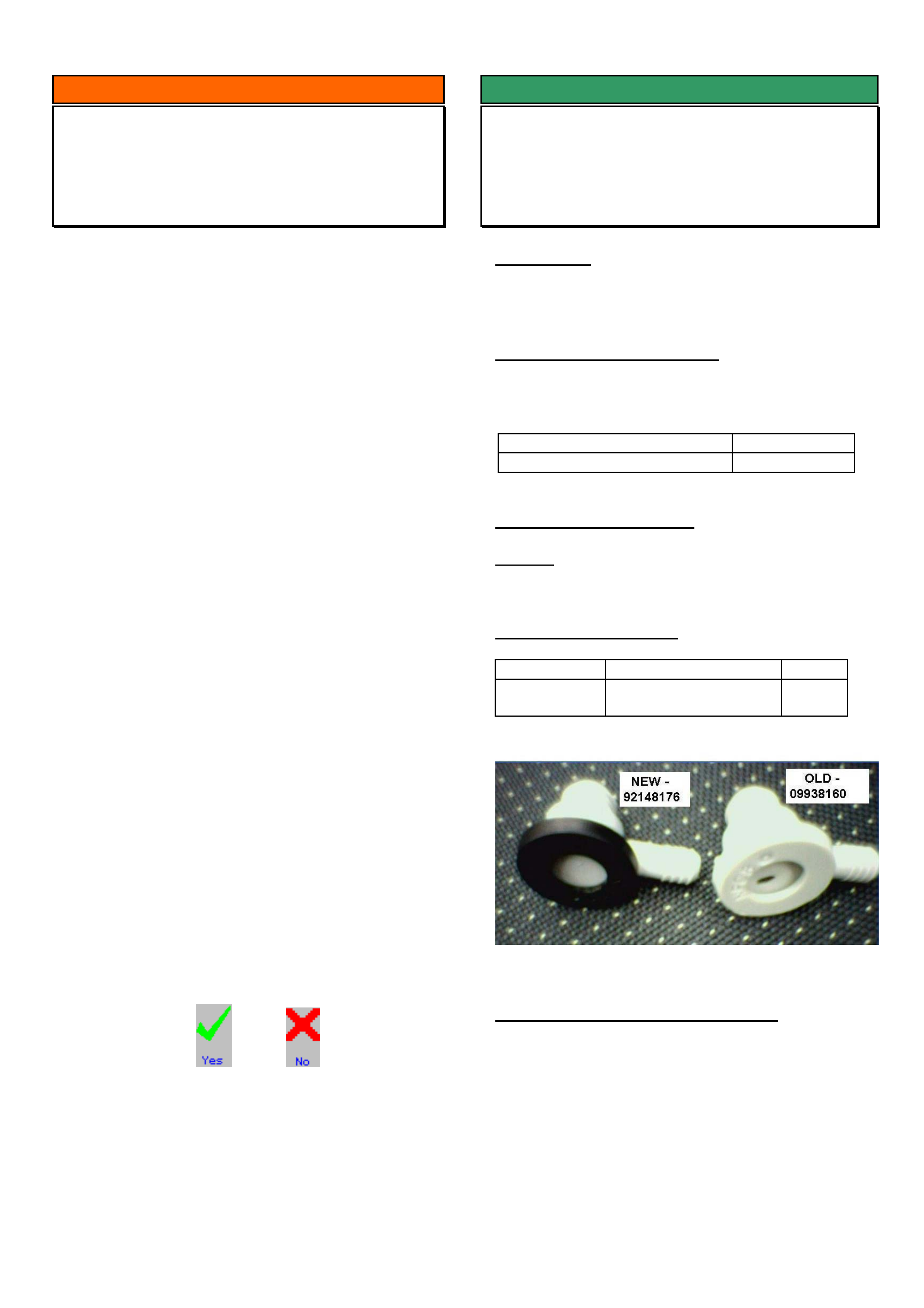
HOLDEN SERVICE TECHLINE __________________________________________________________________JUNE, 2004
9
SERVICE FIX
Brake Booster Check Valve Noisy
VY, V2, WK
(GROUP 5) TL0659-0405
CONDITION
Brake booster check valve noisy in operation.
CORRECTION – Production
Check valves with new rubber diaphragm material
have been fitted to vehicles from:
ISOVIN: Built Date:
**********L242772 26/02/04
CORRECTION – Service
Summary: After verifying that vehicle has condition as
described above, fit a new brake booster check valve.
PARTS INFORMATION
Part No.: Description: Qty:
92148176 Check Valve
Assembly
1
WARRANTY CLAIM INFORMATION
Use Labour Times information in Warranty
Information section of current PV SIP CD
INFORMATION
TIS 2000 – FINDING A CODE INDEX
SB XC TR TS JR JS
(GROUP 12) TL0712-0405
Often TAS receive calls from dealers who are having
trouble locating the code index in TIS 2000 for the
vehicles listed above. The following procedure is
recommended for finding these code indexes.
1. From the TIS 2000 main screen, select
Checking Procedure (Tech 2).
2. Choose Diagnostic Mode, then click Next.
3. Now enter in as many of the Vehicle Details as
possible, then click Next.
4. Double click on the word ‘Vehicle’ and this will
expand to display the vehicle type/model. Then
double click vehicle type/model and it will display
‘General Vehicle Checking Procedure’. Click
on this once to highlight the phrase and then
choose Next.
5. The screen now shown is ‘Validate Vehicle
Options’. This is completely optional but may
help to refine your search. Complete if the
options are known and then choose Next.
6. You will then be prompted to select the
Diagnostic Mode in which to search. For the
models listed above please use ‘Non-Guided’.
7. Now expand group ‘B’ (functional group test) at
the top left of screen by clicking on the + sign.
This will open up a list of all of the functional
groups relating to the vehicle chosen e.g. audio,
instrument, airbag etc.
8. Choose the group you would like the code index
for. Do this by moving the mouse pointer over the
actual word e.g. Audio System, then select once
highlighted. From here you will be required to
use the right of screen and may need to answer
some questions to further refine your search.
9. By using the and symbols at the
lower right of the screen, continue to answer the
questions above until you are presented with the
final table supplying your code index. Note that
you may need to scroll down the page to view
the full table.
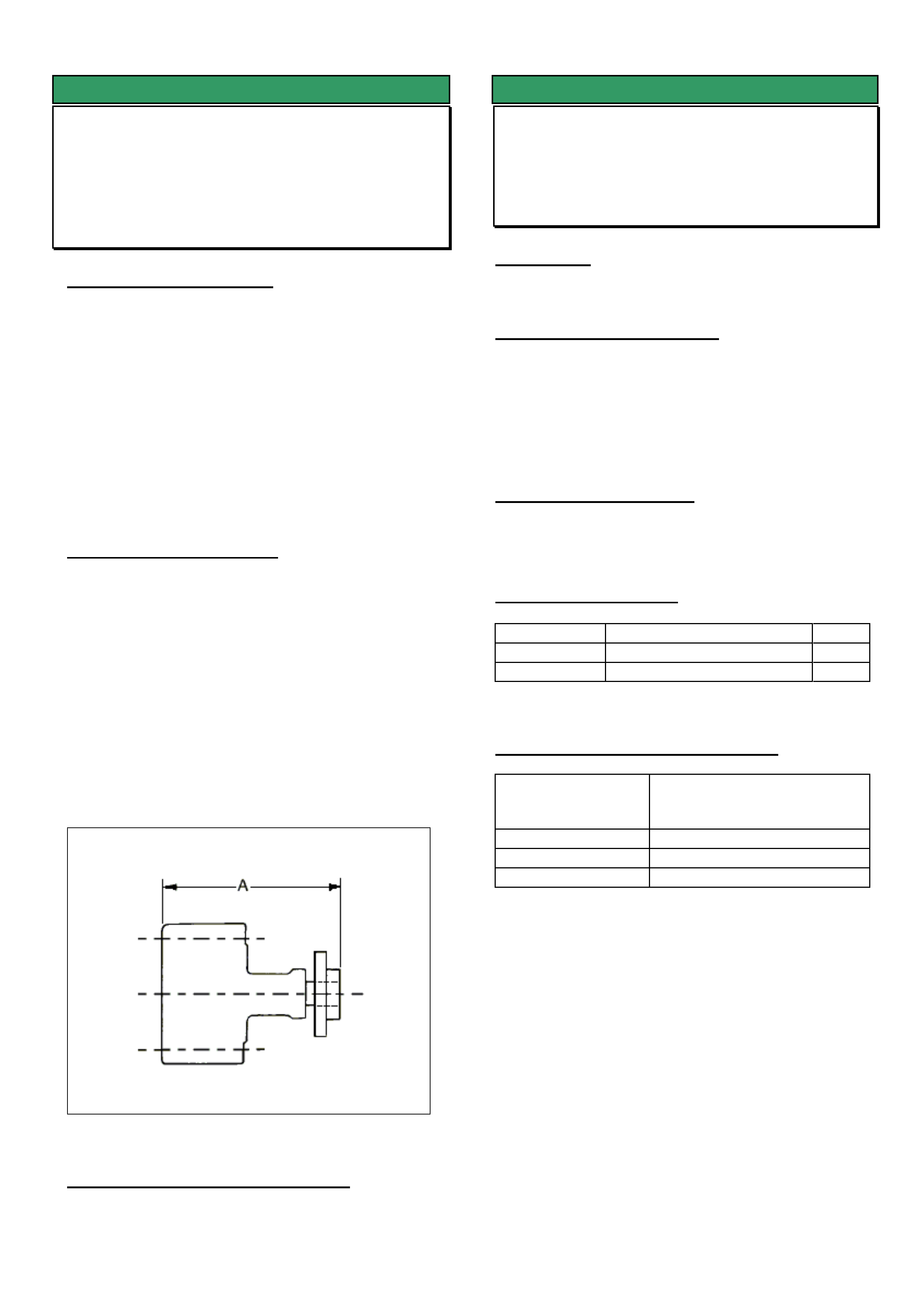
HOLDEN SERVICE TECHLINE __________________________________________________________________JUNE, 2004
10
SERVICE FIX
Drive Belt Squeal - Power Steering Pump
Pulley Misalignment
VY & WK with V6 Engine
(GROUP 6A) TL0671-0405
PROBLEM DESCRIPTION
A squeaking noise from engine bay at idle and while
driving. On closer examination the squeaking noise
can be heard coming from where the accessory belt
rubs on the flange of the power steering pump pulley.
The root cause of this condition may be traced to
misalignment of the power steering pump pulley with
the crank pulley and alternator pulley. Investigation of
cases of misalignment has shown that the pump
pulley hub has not been pressed far enough onto the
pump shaft.
SERVICE RECTIFICATION
Summary: Ensure the pulley hub is located in the
correct position as per following procedure.
1. Remove drive belt and power steering pump
pulley.
2. Using vernier calipers check that the assembled
dimension “A” from the rear of power steering
pump to front of hub equals 128 ± 0.3 mm. Refer
Figure 1.
3. If required, press hub further on to the shaft as
per Holden SIP procedure "3.12 Power Steering
Pump Pulley Hub - V6 Engine" until the 128 ±
0.3mm is achieved.
4. Reinstall all components.
Figure 1.
WARRANTY CLAIM INFORMATION
Use Labour Times information in Warranty
Information section of current PV SIP CD
SERVICE FIX
Tow Bar Tongue Rattle
VY Adventra
(GROUP 1) TL0697-0405
CONDITION
Tow bar tongue rattles in tow bar.
CORRECTION – Production
Tow bars with a threaded hole for an anti rattle bolt
are scheduled for fitment in production in June. When
this occurs, vehicle breakpoint details will be
published in the Service Techline Breakpoint
Summary.
CORRECTION – Service
Summary: On vehicles with tow bar tongue rattle, fit
an “anti rattle” bolt as detailed on next page..
PARTS INFORMATION
Part No.: Description: Qty
11091693 Bolt (M10 x 1.5 x 30mm) 1
92066006 Nut (M10 x 1.5) 1
WARRANTY CLAIM INFORMATION
Description Remove towbar, drill and
tap hole for anti rattle bolt
and reinstall
Labour Op. No. R000115
Time 0.7 hr
Failure Code R0028 Rattle
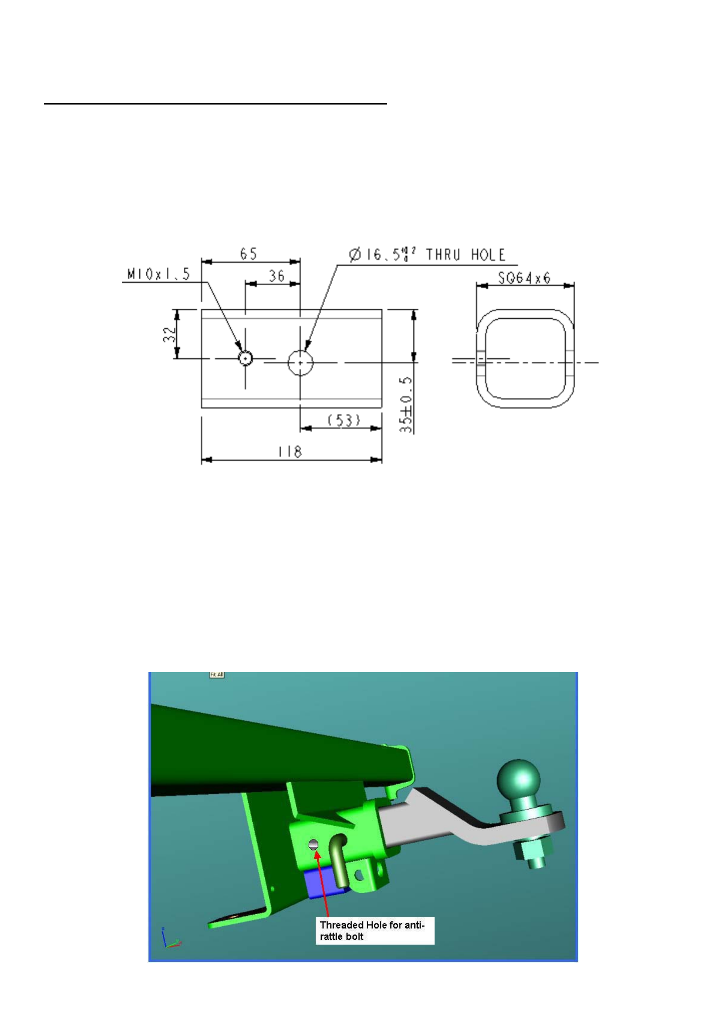
HOLDEN SERVICE TECHLINE __________________________________________________________________JUNE, 2004
11
AWD Wagon Anti-Rattle Bolt Fitment Instructions
Step 1) Remove tongue from towbar.
Step 2) Remove towbar from vehicle.
Step 3) Mark-up position of hole/thread as per drawing below. Note that the thread is on the left side (passenger side)
of the towbar when looking from the rear of vehicle.
Step 4) Drill an 8.5mm hole, and tap an M10 x 1.5 thread at the location specified in the above diagram.
Step 5) Refit towbar to vehicle.
Step 6) Install tongue into towbar and fit hitch/lock pin.
Step 7) Screw bolt 11091693, with locking nut 92066006, into the threaded hole.
Step 8) Torque anti-rattle bolt to 10Nm and secure by tightening locking nut.
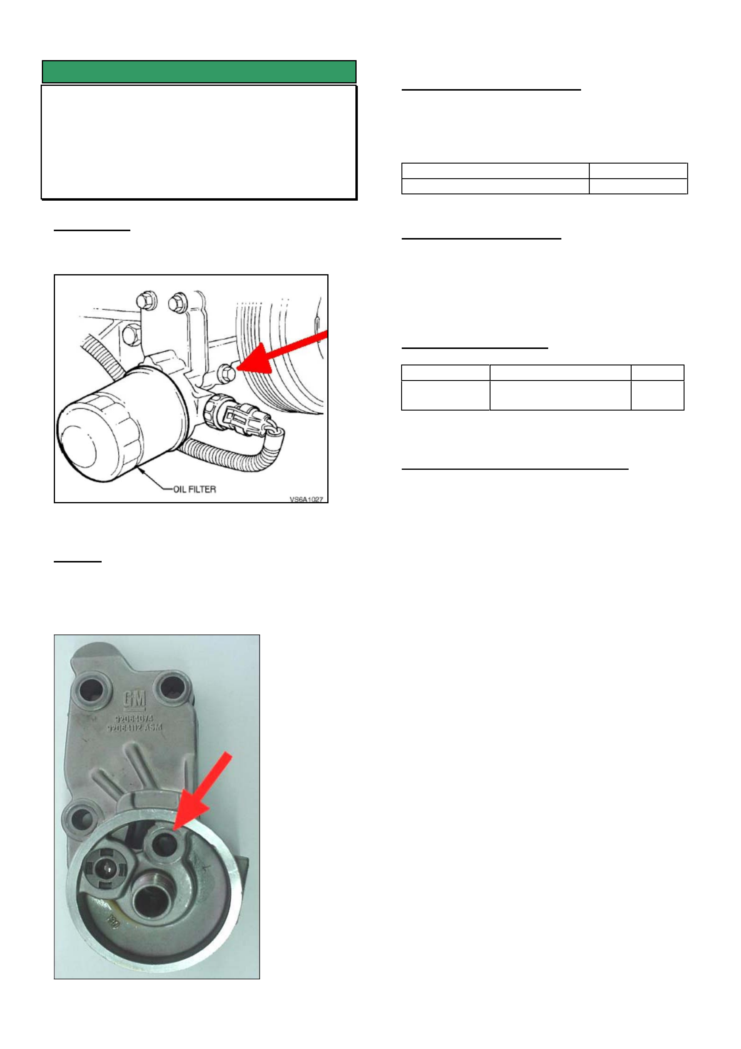
HOLDEN SERVICE TECHLINE __________________________________________________________________JUNE, 2004
12
SERVICE FIX
Engine Front Cover Bolt Oil Leak
Correction
VY with V6 Engine
(GROUP 6A) TL0646-0405
CONDITION
Oil leak from the front timing cover bolt. Refer Figure
1.
Figure 1.
CAUSE
Inadequate sealing surface under the head of the oil
filter adaptor retaining bolt. Refer Figure 2. This
allows oil to travel internally and weep externally from
front timing cover bolt.
Figure 2.
CORRECTION – Production
Revised oil filter adaptors with machining of the
sealing surface under the bolt head have been fitted
to engines in vehicles from:
ISOVIN: Built Date:
6G1YK52A14L268085 20/4/04
CORRECTION – Service
On vehicles with oil leaking from the front timing
cover bolt, fit a revised oil filter adaptor assembly p/n
92067787. For replacement procedure refer to the
Passenger SIP CD.
PARTS INFORMATION
Part No.: Description: Qty:
92067787 Adaptor assembly -
Oil filter
1
WARRANTY CLAIM INFORMATION
Use Labour Times information in Warranty
Information section of current PV SIP CD
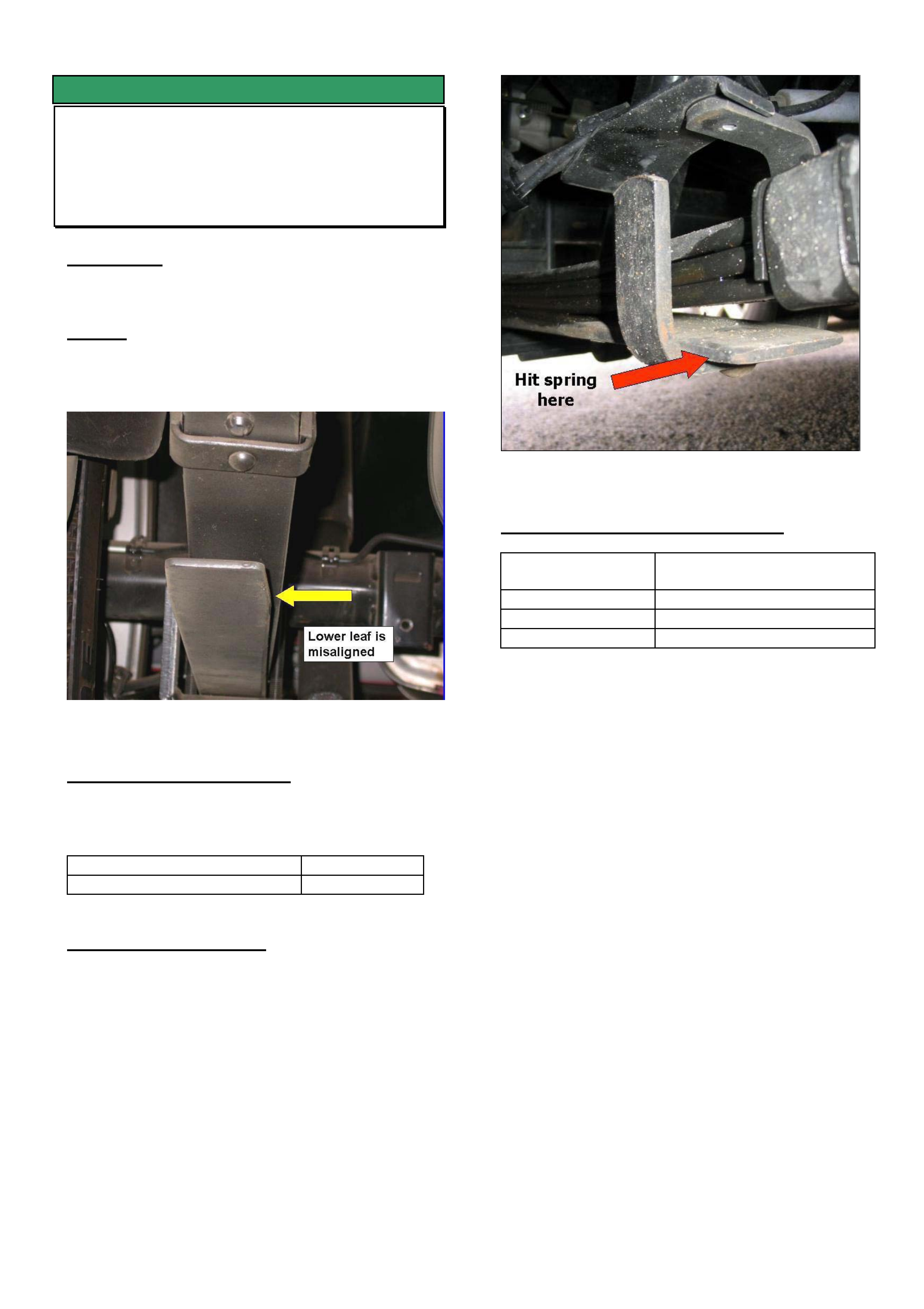
HOLDEN SERVICE TECHLINE __________________________________________________________________JUNE, 2004
13
SERVICE FIX
Rear Spring Squeak
VYII Crewman, Regular Cab, Cross 8
(GROUP 4) TL0700-0405
CONDITION
Rear spring squeaks during suspension movement.
CAUSE
Misalignment of bottom leaf spring causing it to rub
on the spring guide bracket as shown in Figure 1.
Figure 1. LHS spring as viewed from rear end.
CORRECTION – Production
Correctly aligned rear springs have been fitted to
vehicles from:
ISOVIN: Built Date:
6G1YM34FX4L244648 2/3/2004
CORRECTION – Service
Summary: On vehicle with symptoms as described
above, realign bottom leaf of springs on both sides of
vehicle as follows.
Tap side of bottom leaf spring (not bracket) with a
heavy hammer until the leaf is aligned with the triple
leaf pack above it.
Figure 2. Forward section of LHS spring.
WARRANTY CLAIM INFORMATION
Description Realign bottom leaf of rear
springs – both sides
Labour Op. No. F000194
Time 0.3 hr
Failure Code F0025 Misaligned

HOLDEN SERVICE TECHLINE __________________________________________________________________JUNE, 2004
15
INFORMATION
Repairing Vehicles After SRS Deployment
(Refer SIP and TIS2000)
ALL
(GROUP 0B) TL0711-0405
On vehicles involved in accidents that result in airbag
deployment, there are many requirements that need
to be followed with regard to proper repair of the
damaged vehicle. This will include the mandatory
replacement of certain vehicle and airbag system
components.
SIP and TIS 2000 have the latest repair information
which should be adhered to before releasing
previously damaged vehicles back to customers.
Listed below is a quick reference guide to finding this
information for all current model Holden vehicles.
Here you will find the information regarding all Airbag
repair procedures including a full list of mandatory
parts replacement following a deployment.
V & W Car
• Using the latest version of Passenger SIP,
select the model you require from the main
menu, go to
Electrical Section 12M / 2.10, Repairs and
Inspections After an Accident for Version
6.2 SRS or
Electrical Section 12M / 2.6, Repairs and
Inspections After an Accident for Version
8.0/8.1 SRS.
Note: you may need to read the General
Information section first to see if the SRS you
have selected refers you back to a previous
model.
SB, XC, TR, TS, JR, JS, ZC, TT
• Select Service Information from the main
menu of TIS 2000. Click on Standard
Information and then click ‘Next’. Add all
relevant vehicle data in the fields provided and
again click ‘Next’. Tick the boxes named
‘General Vehicle Information’ from the
assembly group as well as ‘Warnings,
Disclaimers, Safety’ from the application box.
Now click ‘Next’.
• As you will see, this is where all General
Warnings and Safety Regulation information is
stored for all functional groups for our imported
vehicles listed above.
• Scroll down to the bottom of the document list
to find the heading
‘Safety Regulations – Restraint Systems’.
Select and then click ‘Next’.
UBS JACKAROO
• Using the latest version of LCV SIP, select the
model you require from the main menu, go to
Electrical Section 12M SRS/ General
Description/Repairs and Inspections
Required After an Accident
RA RODEO
• Using the latest version of LCV SIP, select the
model you require from the main menu, go to
Restraints/Section 9A SRS Servicing/
Repairs and Inspections Required After an
Accident
UES FRONTERA 2001/2002
• Using the latest version of LCV SIP, select the
model you require from the main menu, go to
Electrical/Section 12M2 – SRS/ SRS Airbag
System Inspection Standards for Repair
YG CRUZE
• Using the latest version of LCV SIP, select the
model you require from the main menu, go to
Restraints/Section 10 Restraint System/2.1
Inspection and Repair Required After a
Collision
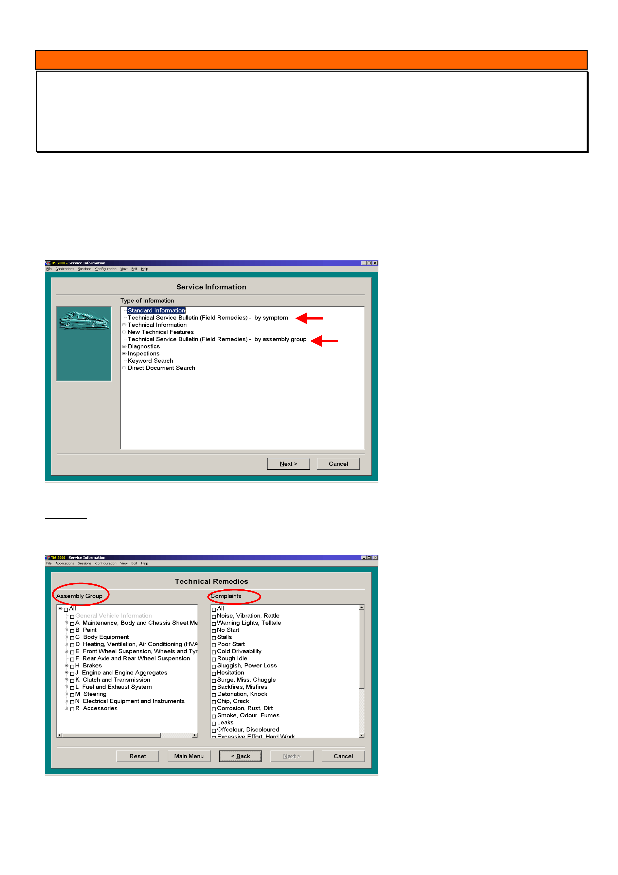
HOLDEN SERVICE TECHLINE __________________________________________________________________JUNE, 2004
16
INFORMATION
Field Service Remedies (Helpful Hints) Available in TIS 2000
JR,JS, & ZC Vectra, TS Astra, SB & XC Barina, TT Zafira,
(GROUP 0B) TL0709-0405
TIS 2000 contains service information on known product issues on Opel based vehicles worldwide.
When confronted with a problem on one of the above listed models for which there is no published Holden Service
Techline, it maybe helpful to refer to TIS 2000 to see if there is a relevant “Field Service Remedy” for the problem
being experienced. To search for this information use the following procedure.
From the main TIS screen, select Service Information. On the Service Information screen (Refer Figure 1) there are
two headings you can select as shown by the arrows.
Figure 1.
Option 1. “Technical Service Bulletin (field remedy) - by symptom” Select this heading then click Next.
The next screen which appears is “Select the vehicle data”. Enter as many of the vehicle details as possible then
click Next. The next screen which appears is shown in Figure 2.
Figure 2
Choose from “Assembly Group” the
group you are interested in. For example:
Body equipment
Heating Ventilation, Air Conditioning(HVAC)
Front Wheel Suspension Wheels and Tyres
Brakes
Engine and engine aggregrates
Clutch and Transmission
Electrical Equipment
etc
Now choose from “Complaints” the actual
symptoms. For Example:
Noise,vibration rattle
Warning lights, telltale
No start, stall
Cold driveability, rough idle
Backfires, misfires
Corrosion, rust, dirt,
Leaks
Poor operation, incorrect operation
etc
Now click Next. What appears next is a list of Field Remedies in which there may be one or more known issues
relating to the area of your selection that may have valuable information to help assist in your diagnosis.
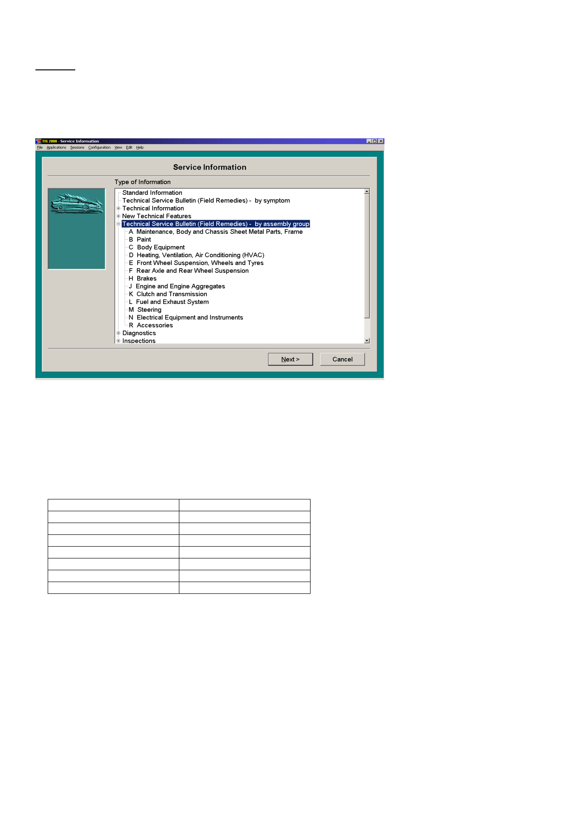
HOLDEN SERVICE TECHLINE __________________________________________________________________JUNE, 2004
17
Option 2. “Technical Service Bulletin (field remedy) - by assembly group.” Select this heading then click Next.
The next screen which appears is “Select the vehicle data”. Enter as many of the vehicle details as possible then click
Next. The next screen which appears is shown in Figure 3.
Now choose the area of the vehicle you are interested in and click Next. For example if you select “Steering”, a list of
field remedies (if any) will be displayed on steering issues. If there are no field remedies for that particular assembly
group it will be “greyed out”.
Figure 3.
IMPORTANT:
Remember that not all Field Remedies are applicable to Opel vehicles imported into Australia. When reading a Field
Remedy it is important to check that the model, engine, transmission and any options specified are relevant to
Australian vehicles.
The following table gives the equivalent Opel Model designation
Holden Designation Opel Designation
JR/JS Vectra Vectra - B
ZC Vectra Vectra - C
TR Astra Astra - F
TS Astra Astra - G
TT Zafira Zafira
SB Barina Corsa - B
XC Barina Corsa - C
NOTE: Found within these Field Remedies there may be labour operation details, that are not applicable to the
Australian Market. Also, special part numbers are sometimes mentioned but are not listed in Partfinder and are also
not available from HSPO.
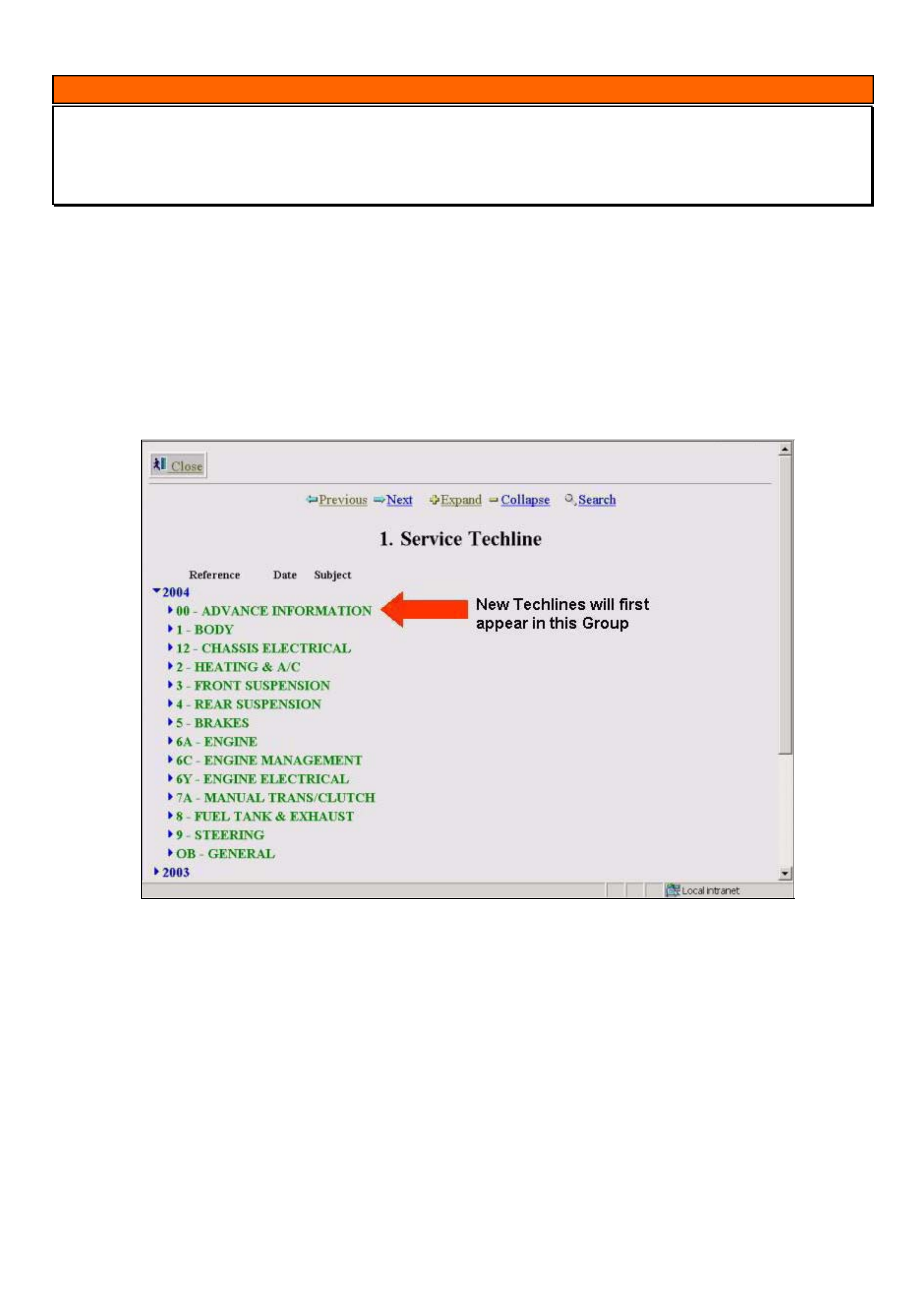
HOLDEN SERVICE TECHLINE __________________________________________________________________JUNE, 2004
18
INFORMATION
Service Techlines “On- Line” – New Group “00 Advance Information”
(GROUP OB) TL0698-0405
In order to speed up the process for providing the latest service fix information to the Holden Dealer network the
following procedure is now operational.
New Service Techlines are now placed onto the Holden Lionheart Portal as soon as they have been approved for
release.
They will first appear in the group “00 – Advanced Information”.
The “Reference” will be the issue number of the next full issue of Service Techlines to be printed.
Once the next issue has been printed and delivered, each individual Techline in group “00 – Advanced
Information” will be moved into its relevant grouping. For example, an item on brakes will be moved into Group
5.
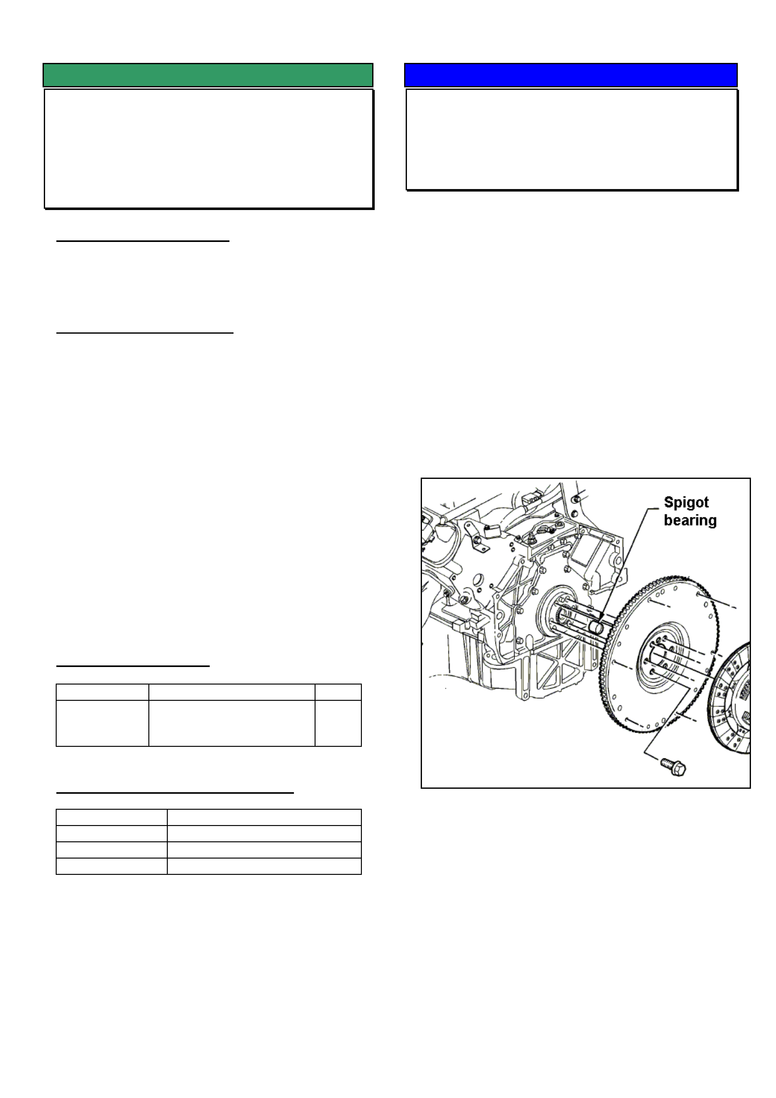
HOLDEN SERVICE TECHLINE __________________________________________________________________JUNE, 2004
19
SERVICE FIX
Supercharger Belt Chirp/Squeal on Cold
Start
V & W with Supercharged V6
(GROUP 6A) TL0487-0405
PROBLEM DESCRIPTION
Some customers may report a belt squeal or chirp for
a short time during engine cold starts.
SERVICE RECTIFICATION
Summary: Fit a new supercharger drive belt.
For complaints of belt ‘chirp’ or ‘squeal’ on start-up,
replace the existing drive belt with a new belt, part
number 92062955 or 92067829
Ensure that the new belt to be fitted carries part
number 92062955 or 92067829 on the outer surface
of the belt.
Before returning the vehicle to the customer, carry
out a quick supercharger drive belt system alignment
check – by running a long straight edge over the
pulleys, to ensure the tensioner or idler pulleys are
not out of alignment by more than 2mm.
Should the tensioner or idler pulleys be out of
alignment by more than 2mm – replace the relevant
pulley and mounting to ensure alignment is
corrected.
PARTS INFORMATION
Part No. Description Qty
92062955
or
92067829
Belt - Supercharger 1
WARRANTY CLAIM INFORMATION
Description Supercharger Belt - Replace
Labour Op. No. J607050
Time 0.2 hr
Failure Code J0040 (noisy)
SERVICE PROCEDURE HINT
Spigot Bearing Installation Precaution
Gen III V8 engine & Manual Transmission
(GROUP 6A) TL0703-0405
This is a reminder to Technicians that replacement
engine assemblies generally do not come with a
spigot bearing installed. For manual transmission
vehicles, this bearing will need to be ordered and
fitted prior to engine installation.
NOTE: Failure to fit a spigot bearing will result in
excessive vibration when operating clutch pedal.
On the other hand, when installing a replacement
engine in an automatic transmission vehicle,
ensure that a spigot bearing has not been installed
by mistake.
In this situation, when the torque convertor is bolted
up to the flex plate, the spigot bearing will dislodge
the welch plug in the end of the crankshaft resulting
in an external oil leak.
Figure 1. Manual Transmission engine shown
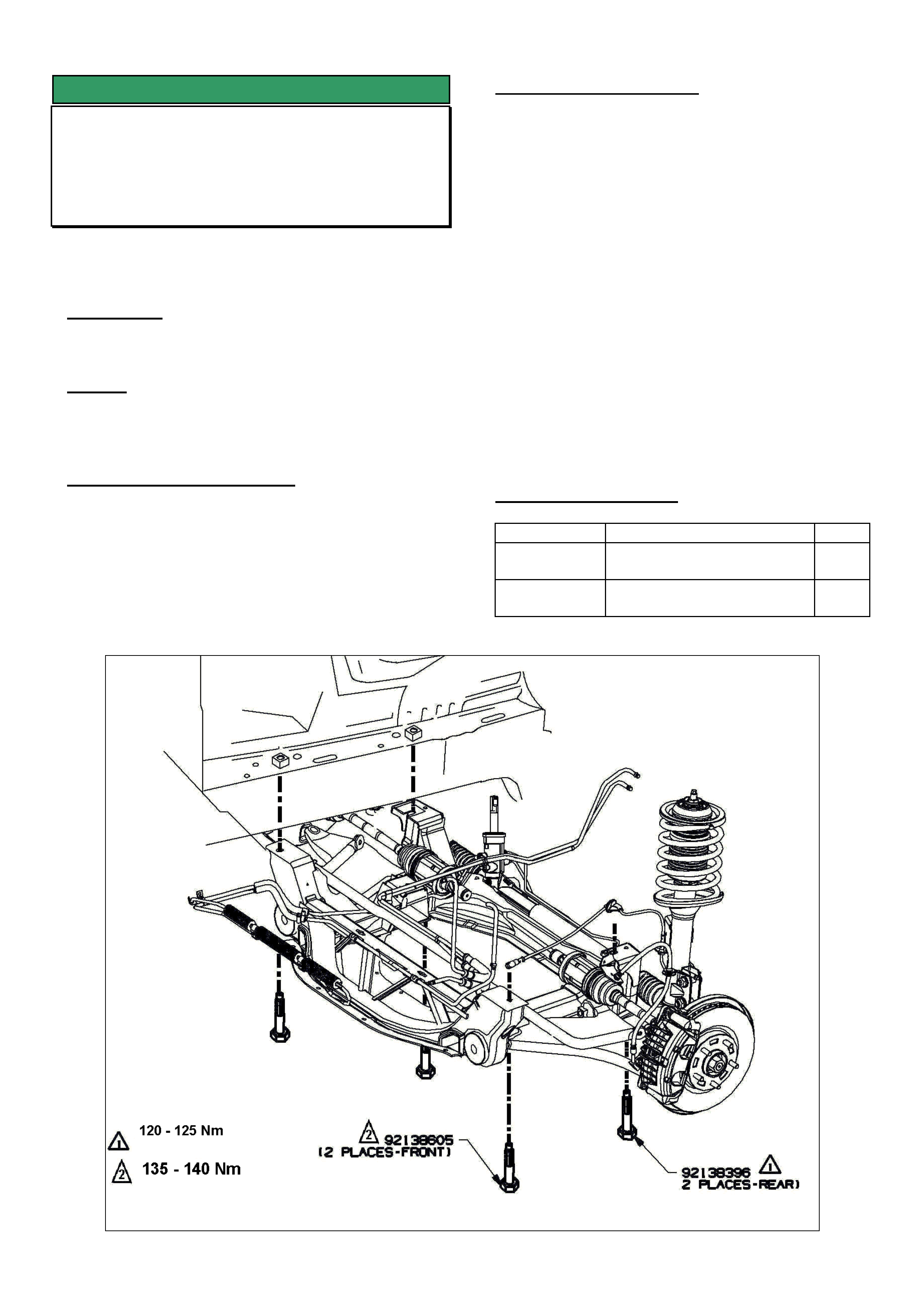
HOLDEN SERVICE TECHLINE __________________________________________________________________JULY, 2004
5
SERVICE FIX
Front Suspension Clunk (Front Subframe)
VY Adventra
(GROUP 3) TL0718-0406
Technicians should also refer to Techline TL0638-
0403 published in Issue 3, 2004. which gives another
possible cause for front suspension clunk
CONDITION
Clunk from front suspension usually heard when
wheel impacts deep pot hole.
CAUSE
One possible cause for this condition is fore-aft
movement of the front subframe relative to the body
due to insufficient clamp load at the attaching points.
CORRECTION – Production
Correction in progress at time of publication.
Breakpoint information will be published when it
becomes available.
CORRECTION – Service
Summary: Check existing subframe mounting bolt
torques. If loose, replace mounting bolts and tighten
to torque settings as shown below.
1. Check tightness of existing bolts using “follow on”
torque method. If torques are below the values in
steps 3 & 4 then proceed to step 2. If torques are
above these values then this techline procedure is
not applicable.
2. Replace all 4 subframe mounting bolts one at a
time with new parts.
NOTE: These are “micro encapsulated” bolts
which have a locking compound on the threads
and should only be reused once. As a general
rule, if in doubt as to previous useage, always
replace a micro encapsulated fastener.
3. Torque the two front bolts to 135-140 Nm.
4. Torque the two rear bolts to 120-125 Nm.
PARTS INFORMATION
Part No.: Description: Qty
92138605 Bolt Front suspension
frame - front
2
92138396 Bolt Front suspension
frame - rear
2

HOLDEN SERVICE TECHLINE __________________________________________________________________JULY, 2004
6
SERVICE FIX
Low Clutch Pedal, Difficult To Select
Gears, Vibration In Pedal At Idle (Pressure
Plate Bolts Loose)
All with Gen III 6-speed M/T
(GROUP 7A) TL0723-0406
CONDITION
Low clutch pedal engagement and disengagement,
difficult to select gears, vibration through clutch pedal
at idle or clutch fluid leaking.
A possible cause for the above conditions is loose
clutch pressure plate bolts.
CORRECTION – Production
The pressure plate bolt torque has been revised to 70
+/- 7 Nm on vehicles from:
ISOVIN: Built Date:
**********L234149 12/2/2004
CORRECTION – Service
Summary: After verifying that vehicle has symptoms
as described above, proceed as follows.
NOTE: Always refer to Holden SIP CD for any
procedures not detailed in this techline.
1. Switch engine off and check clutch pedal feel. The
clutch pedal should feel firm (with no spongy feel)
throughout the complete travel. Start engine and
re-check clutch pedal feel. If the clutch pedal
becomes spongy or soft on the initial travel this is
an indication that the pressure plate bolts are
loose.
2. When inspecting the clutch, look for uneven
pressure plate finger heights or a gap between the
pressure plate and flywheel both of which indicate
loose pressure plate bolts.
3. Remove slave cylinder release bearing and
inspect stroking sleeve on slave cylinder for
abnormal wear. Replace slave cylinder assembly
only if the stroking sleeve is worn.
4. Remove pressure plate and flywheel assembly
and reset self adjusting mechanism prior to
reinstalling into vehicle. Refer to Passenger SIP
CD for procedure.
5. Replace clutch pressure plate and flywheel
assembly and driven disc only if there is damage
to the components (eg. cracks)
6. Replace pressure plate bolts with new bolts from
HSPO and tighten to 70+/-7Nm
Tighten bolts in correct sequence in 4 stages :
Stage 1 Tighten all bolts to 15 Nm
Stage 2 Tighten all bolts to 35 Nm
Stage 3 Tighten all bolts to 55 Nm
Stage 4 Tighten all bolts to 70 Nm
Pressure plate bolt tightening sequence
PARTS INFORMATION
Refer to Partfinder for current part numbers.
WARRANTY CLAIM INFORMATION
Use Labour Times information in Warranty Information
section of current PV SIP CD
1
23
4
5
6
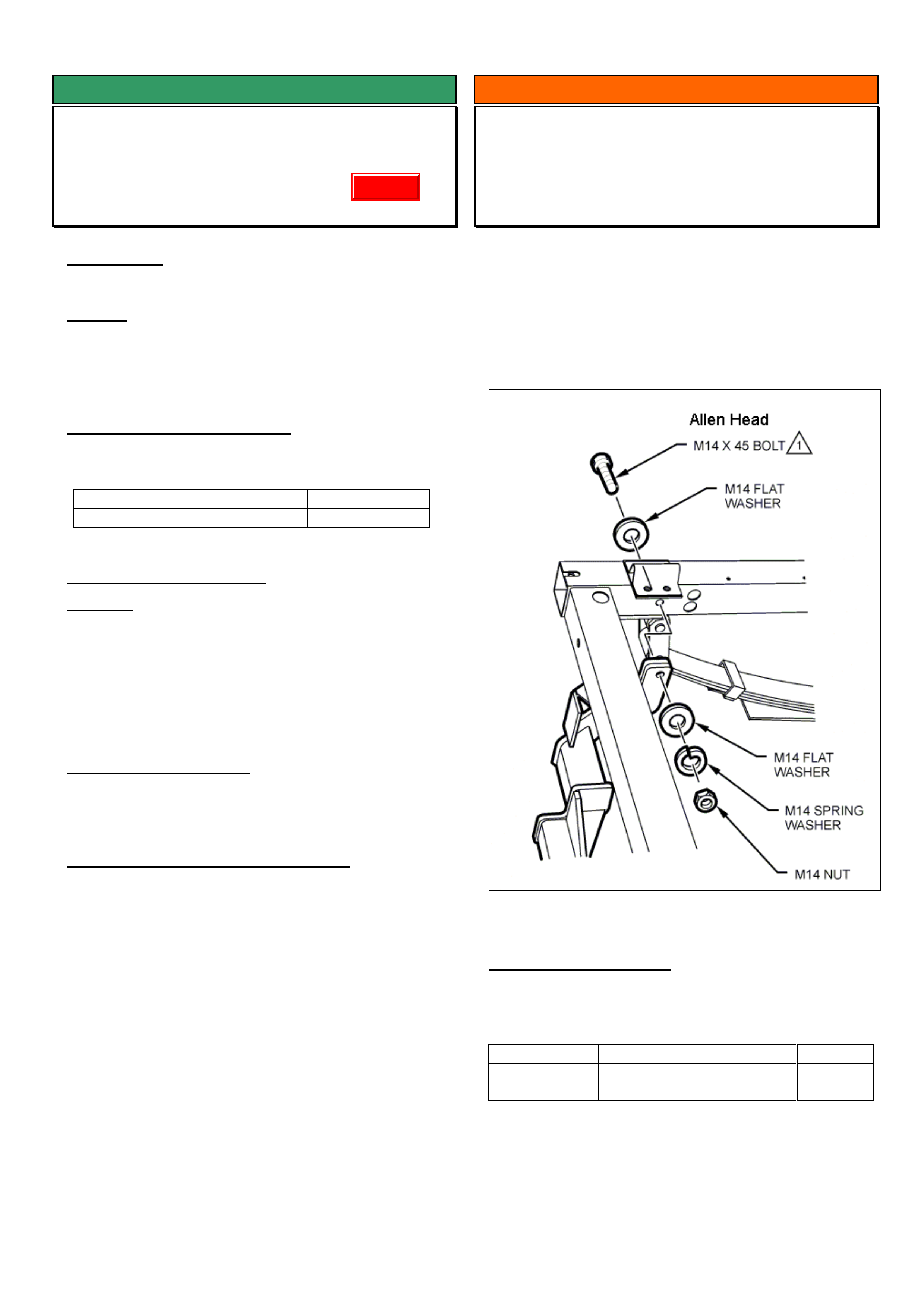
HOLDEN SERVICE TECHLINE __________________________________________________________________JULY, 2004
7
SERVICE FIX
Door Lock Malfunction
VY, WK, V2
(GROUP 1) TL0667-0406
CONDITION
Door lock will not unlock or lock intermittently.
CAUSE
This condition may be due to binding up of the lock
mechanism due to insufficient operating clearances in
the linkages.
CORRECTION – Production
Locks produced with modified operating clearances
within the linkages have been fitted to vehicles from:
ISOVIN: Built Date:
**********L225024 20/01/2004
CORRECTION – Service
Summary: After verifying that vehicle has symptoms as
described above, fit a new lock assembly from
Holden Service Parts Operation (HSPO).
NOTE. All lock assemblies currently available from
HSPO have been checked for correct operating
clearances in the linkages.
PARTS INFORMATION
Refer to Partfinder for part numbers
WARRANTY CLAIM INFORMATION
Use Labour Times information in Warranty Information
section of current PV SIP CD
INFORMATION
HSPO Tow Bar Attaching Bolt Revised
VY Crewcab
GROUP 1 TL0630-0406
To enable better access for a tightening tool, the tow
bar attaching bolts shown in Figure 1 have been
changed from hexagon head to Allen head type bolts.
This change took effect from 16th March 2004 at
Holdens supplier of tow bars.
Figure 1.
PARTS INFORMATION
NOTE: The two Allen head bolts come as part of the
tow bar small parts kit.
Part No.: Description: Qty:
92606817 Small parts kit – tow bar
assembly
1
Update
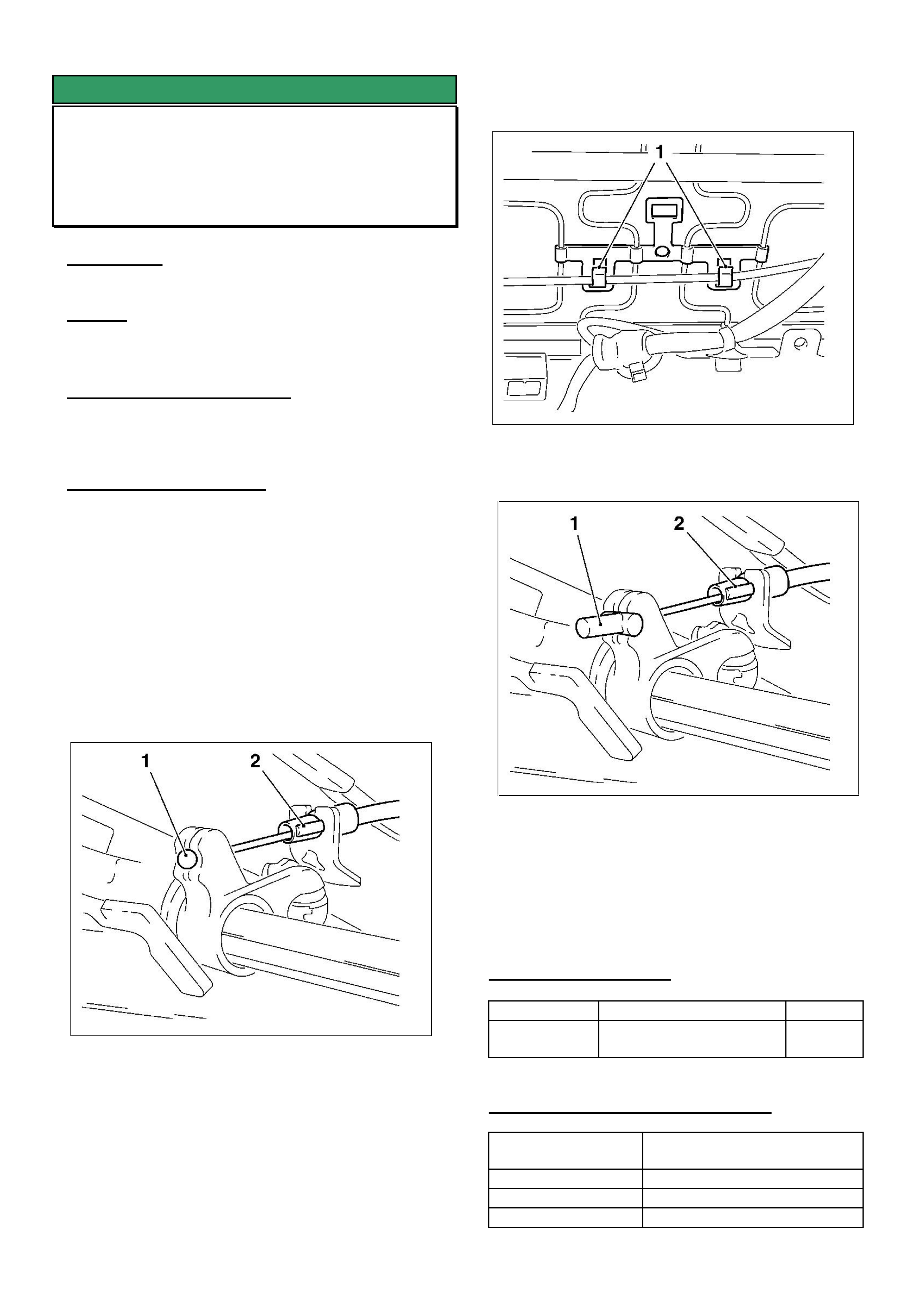
HOLDEN SERVICE TECHLINE __________________________________________________________________JULY, 2004
8
SERVICE FIX
Front Seat Adjuster Cable Dislodges
ZC Vectra
(GROUP 1) TL0688-0406
CONDITION
Cannot adjust front seat forwards or rearwards.
CAUSE
Front seat adjusting cable (with ball end) dislodges
CORRECTION – Production
Revised adjustment cable with cylindrical shaped end
have been fitted to vehicles from 6/6/2003:
CORRECTION – Service
Summary: On vehicles with condition as described
above, fit a new seat adjustment cable with cylindrical
end.
Procedure.
1. Remove front seat.
Refer TIS procedure “ Front Seat, Remove and
Install”, group “C”, Service Instruction Vectra-C.
2. Remove adjuster cable (1) from seat adjustment
guide by clipping off holder (2) Refer Figure 1.
Figure 1.
3. Remove cable from retaining clips. Refer Figure 2.
Figure 2
4. Install new adjuster cable. Refer Figure 3.
Figure 3
5. Reinstall front seat.
Refer TIS procedure “ Front Seat, Remove and
Install”, group “C”, Service Instruction Vectra-C.
6. Repeat procedure for other front seat.
PARTS INFORMATION
Part No.: Description: Qty:
13100008 Cable adjustment front
seat
1 per
seat
WARRANTY CLAIM INFORMATION
Description Replace seat adjuster cable
– both seats
Labour Op. No. C000520
Time 0.7 hr
Failure Code C0071 Pulls Loose
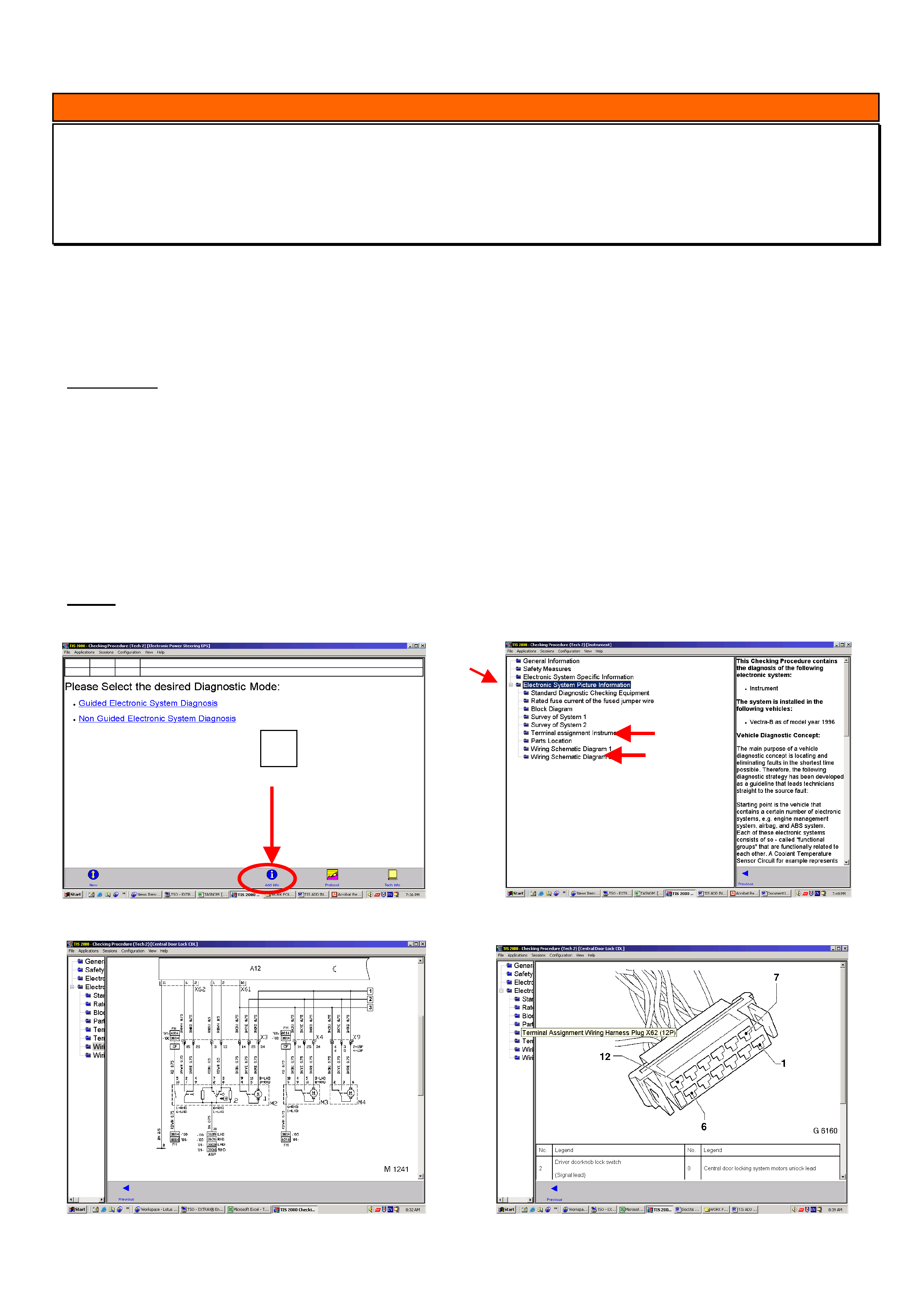
HOLDEN SERVICE TECHLINE __________________________________________________________________JULY, 2004
9
INFORMATION
Electrical Circuit Information, (Additional Information) Found in TIS 2000
SB, TR, TS, JR, JS, (Some info. XC, TT,)
(GROUP 12) TL0732-0406
TIS 2000 contains extra information relating to electrical circuits, wiring connector end views, (known as Terminal
Assignments), electrical component locations, and other valuable information regarding vehicle electrical systems.
This Additional Information which is found within “Checking Procedures,” relates to the Opel range of vehicles NOT
FOUND in the usual TIS 2000 Wiring Diagrams section.
The Additional Information is for the electrical systems in which TECH2 IS USED for diagnosis,
For example:
Engine Multi Information Displays Immobiliser
Transmission Instruments Air bag
Anti Lock Brakes Audio Systems Central Locking
Electric Hydraulic Steering
This information can be found within “Checking Procedures” by selecting the blue colored “ADD INFO” icon at the
bottom of the screen, Refer Figure 1. Next displayed is the selection menu shown in Figure 2. Click on the “+” box
for “Electrical System Picture Information”. Then you have a choice of Block Diagrams, Terminal Assignment, Parts
Location, and Wiring Schematic which may be divided into two or more separate diagrams.
Pictures of circuit diagrams, connector terminal pin outs along with all necessary abbreviations are shown in Figures
3 and 4.
NOTE: There is also some Electronic System Picture Information for the later range of Opel product such as
XC Barina, TT Zafira, but for ALL Opel vehicles as of MY02, this information is found in TIS 2000 Wiring Diagrams.
Figure1. Figure.2
Figure 3 Figure 4
+
Add Info
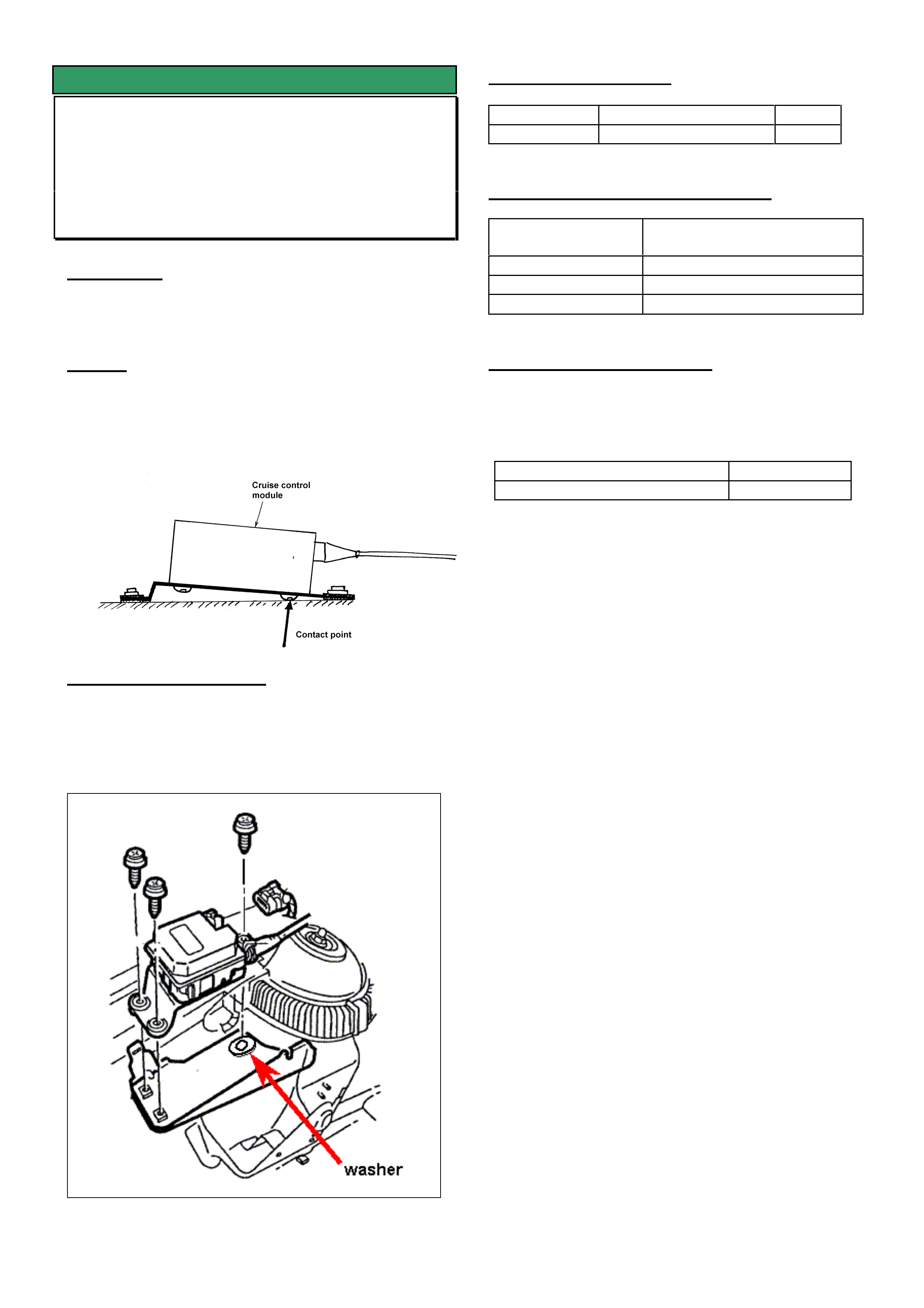
HOLDEN SERVICE TECHLINE __________________________________________________________________JULY, 2004
10
SERVICE FIX
Noise when Cruise Control is Activated or
Deactivated
VY, WK all with Cruise Control
(GROUP 12) TL0717-0406
CONDITION
A knock or thud noise can be heard in some vehicles
when the cruise control is activated and/or deactivated.
CAUSE
This noise is caused by a lack of clearance between
the cruise control module and the ABS/cruise control
module mounting bracket and is transmitted into the
cabin through the body.
CORRECTION – Service
Add washer 92094572 to rear mounting point as
shown in Figure 1 to give clearance between the cruise
control module assembly and the sheet metal bracket.
Figure 1. Add spacer washer to rear mounting point
PARTS INFORMATION
Part No.: Description: Qty:
92094572 Washer 1
WARRANTY CLAIM INFORMATION
Description Add spacer washer to
cruise control module
Labour Op. No. R000118
Time 0.3 hr
Failure Code R0040
CORRECTION – Production
The sheetmetal bracket the cruise control module is
bolted to has been modified to provide clearance to
bolt heads. Fitted to vehicles from:
ISOVIN: Built Date:
**********L300701 22/6/2004

HOLDEN SERVICE TECHLINE _________________________________________________________________AUGUST, 2004
5
DIAGNOSIS HINT
DTC’s P0335 & P0340 Crankshaft and
Camshaft Sensor “INCORRECT” Signal
All Opel Engines
(Group 6C) TL0754-0407
PROBLEM DESCRIPTION
TAS receives many calls relating to crankshaft and
camshaft sensor diagnostics, P0335 and/or P0340
sensor(s) incorrect signal.
Dealers are reporting that after extensive diagnosis of
the wiring and connections, the sensors and/or ECU
have been replaced, the DTC’s are still present.
The DTC description of “Incorrect Signal” differs from
“No Signal”. A DTC for either sensor referring to
incorrect signal usually means the signal is present,
but may not be correct or complete due to a mismatch
between the two sensors.
POSSIBLE CAUSE
Incorrect cam timing can cause either of these codes
to set. Often these codes may appear shortly after a
service where the cam belt required replacement or
any other reason where the timing belt required
removal then reinstallation.
If, after thorough diagnosis of the sensor and all
associated wiring, connectors and terminals, no fault
can be found, be sure to check for correct camshaft
timing.
INFORMATION
Vehicle Search Function in SIP and NOW
All
(Group OB) TL0753-0407
Due to a technical problem, the vehicle search
function was removed from PV SIP 6.5 but was able
to be reinstated on SIP 6.6.
It should be noted that vehicle searches can now be
performed using the New Online Warranty system
(NOW). The information received from New Online
Warranty system (NOW) is the latest and most
accurate information available.
For information on using the New Online Warranty
system (NOW) contact the Warranty Administration
Department. Contact numbers are listed in the April
Techline issue 3/2004.
SERVICE PROCEDURE
Telematics Module Change Over
Procedure
VX VY WH WK V2
(Group 12) TL0752-0407
PROBLEM DESCRIPTION
Australian Arrow have advised that they have
received a number of returned telematics modules
where the module is still registered to the vehicle it
was removed from. This indicates that the
replacement module has not been registered with
Holden Assist as only one module can be registered
against a vehicle at any one time.
CORRECT PROCEDURE
It is a requirement of the change over procedure that
the replacement telematics module be “tested &
registered” after it is fitted to the vehicle. This is done
by pressing the Holden Assist button on the mirror
and registering the vehicle details with Holden Assist.
Please refer to the telematics change over procedure
whenever you are required to replace a telematics
module. This can be found in Passenger Vehicle SIP.
NOTE. Failure to carry out the above procedure will
result in the Holden Assist system not having the
correct vehicle details registered against the
telematics module in the customers vehicle.
SERVICE FIX
Park Brake Shoe Scrape
VT, VX, VU, V2, WH, WK
VY with IRS only
(Group 5) TL0452B-0407
This techline supercedes the previous one (TL0452A-
0404) published in Issue 4, 2004. It is revised by
clarifying which models the service fix can be applied
to. Note that the park brake shoe scrape kit cannot
be fitted to vehicles with a “live” axle, e.g. VY regular
and crew cab.
Please mark your printed copies with this revision.
The revised techline can be found on the Holden
Lionheart Portal.
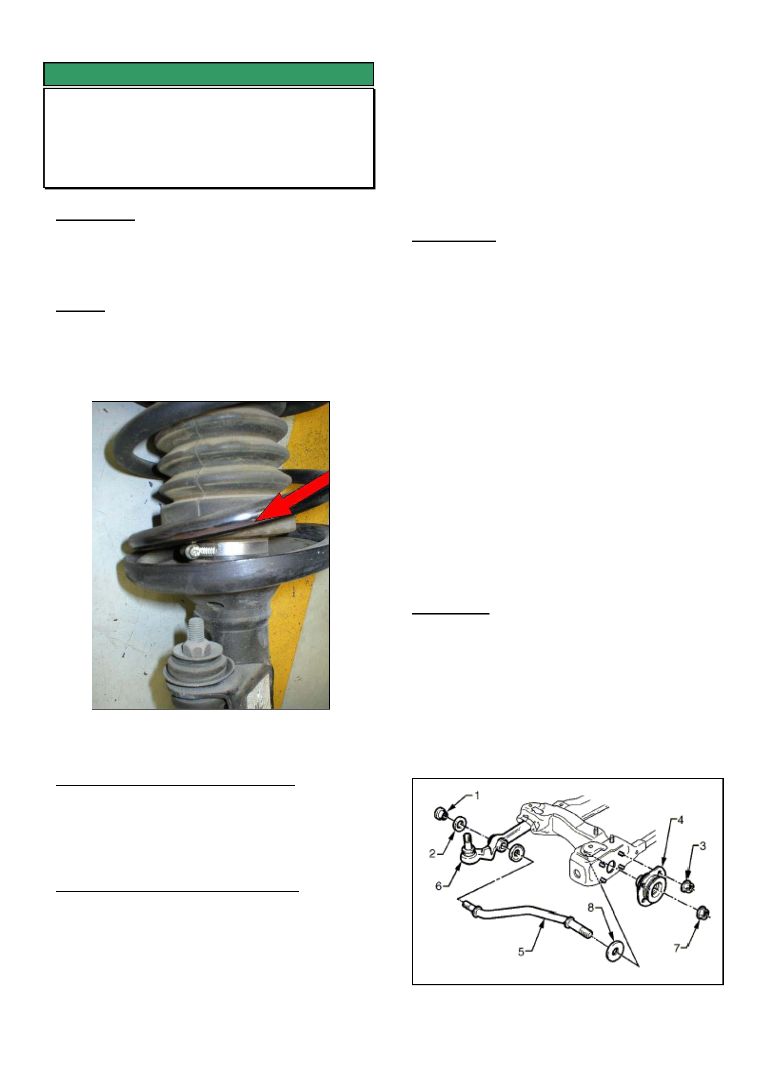
HOLDEN SERVICE TECHLINE _________________________________________________________________AUGUST, 2004
8
SERVICE FIX
Front Strut Spring Noise
VX, VY, V2, WH, WK
(Group 3) TL0746-0407
CONDITION
A knock/graunch noise from front suspension when
driving at low speeds over speed humps, gutters
undulating roads etc.
CAUSE
Possible causes for the above condition are:
1. Lower coil of the spring touching on side lip of
spring seat. Refer Figure 1.
2. Spring coils touching on body sheet metal within
the wheel arch area.
Figure 1. Shows rub mark on spring coil
CORRECTION – Vehicle Production
Production changes are in progress to rectify this
condition. Breakpoint details will be advised in a
future techline.
CORRECTION – Vehicles in Service
Note: For procedures not given in detail, refer to PV
SIP.
Diagnosis.
1. Check tightness of all front suspension fasteners.
If all ok proceed to step 2.
2. Inspect body sheet metal around inside of strut
tower (wheel arch) for signs of spring coil rubbing.
3. Inspect the second lower coil on inboard side of
spring for signs of chipped or marked paint as
shown in Figure 1.
4. If witness marks are evident in above steps 2 & 3,
go to procedure A.
Procedure A (Both sides of vehicle)
1. Remove spring from strut assembly and re install
upside down. i.e. with the thin coil end resting on
the spring seat.
2. Carefully reinstall the upper bearing (yellow
plastic housing) ensuring that it is located
correctly in the upper spring seat.
3. While the strut is removed from the vehicle, cycle
the control arm up and down. If a graunching
noise is heard from the lower control arm rod front
hydraulic bush, then do procedure B after
completing step 4.
4. Reinstall strut assembly into the vehicle.
Install new strut to steering knuckle attaching
bolts and nuts. Tighten bolts while applying
pressure to the top of the brake rotor ensuring
that the camber adjustment bolt is against the
strut tube. This removes the need to perform a
front-end alignment.
Procedure B (Only do this if the check in Procedure
A, step 3 confirms it is required)
1. Remove the front lower control arm rod nut.
(Number 7 in Figure 2)
2. Install new nut as specified in SIP, but do not fully
tighten yet.
3. Bounce the front of the vehicle up and down
several times to settle the suspension.
4. Torque the control arm rod nuts to 140 – 155 Nm
as specified in SIP.
Figure 2.
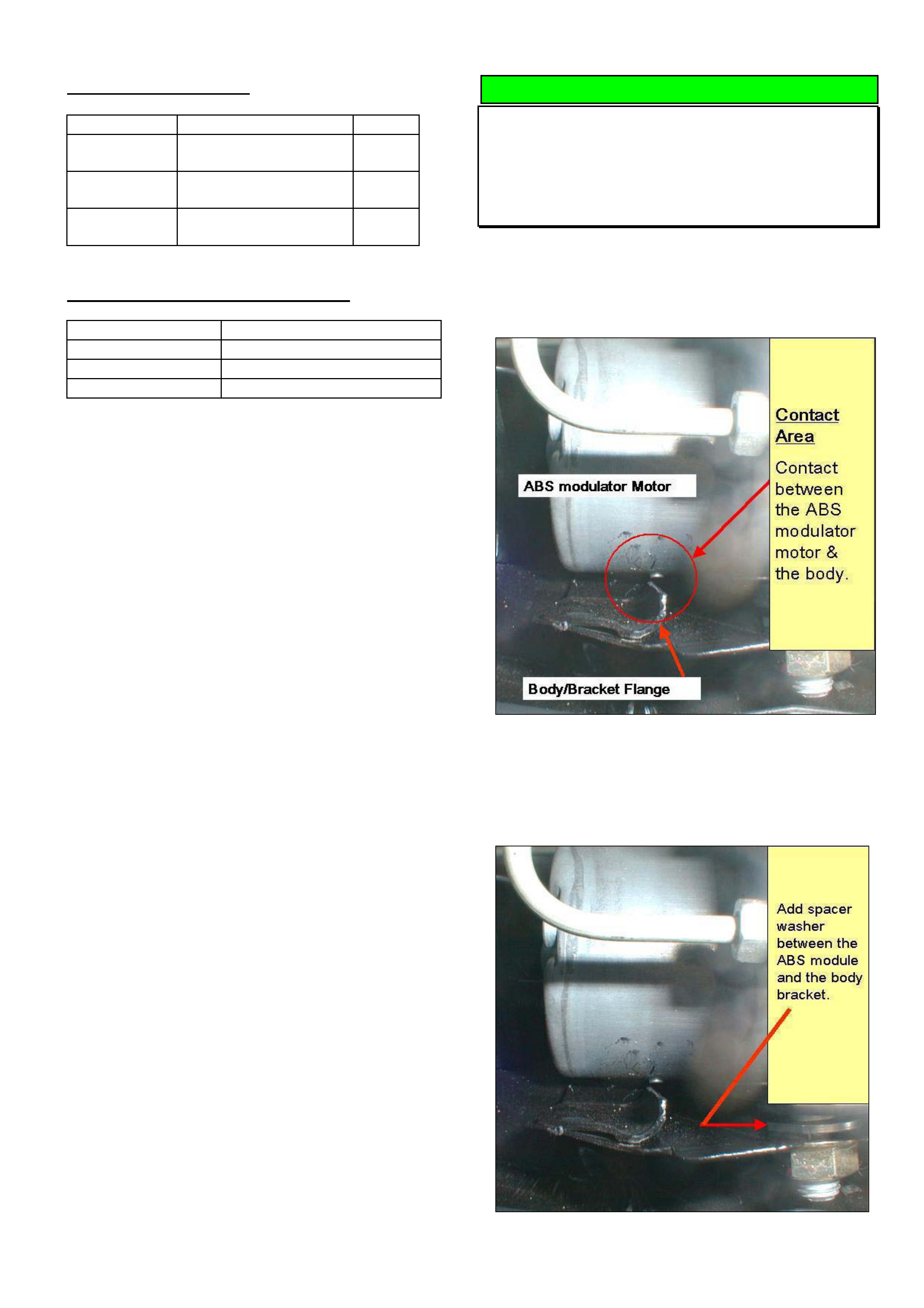
HOLDEN SERVICE TECHLINE _________________________________________________________________AUGUST, 2004
9
PARTS INFORMATION
Part No.: Description: Qty:
11090821 Bolt – front
suspension strut
4
92138205 Nut – front
suspension strut
4
11084241 Nut – control arm rod
lower
2
WARRANTY CLAIM INFORMATION
Description Invert spring – both sides
Labour Op. No. E000370
Time 1.7 hrs
Failure Code E0040 Noisy
DIAGNOSIS HINT
Excessive Noise During ABS Self test
VX, VY, WH, WK
(Group 5) TL0734-0407
The characteristic noise/pulsation generated by the
ABS modulator during “self test”, can be made worse
if the modulator motor rubs on the mounting bracket
as shown in Figure 1.
Figure 1
To increase the clearance between modulator motor
and bracket, insert a spacer washer as shown in Figure
2.
Figure 2.

HOLDEN SERVICE TECHLINE _________________________________________________________________AUGUST, 2004
10
SERVICE PROCEDURE
A/T Cooler Flush & Flow Rate Check
Requirement
V & W – with A/T
(Group 7B) TL0748-0407
CONDITION
Returned parts analysis shows that there is often
debris from failed transmissions causing cooler
blockages.
Failure to reverse flush, and carry out a transmission
cooler flow rate check may result in a repeat
transmission failure, if a cooler blockage exists.
SERVICE RECOMMENDATION
It is recommended that Service Managers, Workshop
Controllers or Service Advisors advise technicians to
perform a cooler flush and flow rate check by adding
the wording “Cooler Flush & Flow Rate Check
Required” to Repair Orders whenever:
• a changeover or replacement transmission is
installed.
• fluid contamination is suspected.
• whenever the oil pump and/or torque converter is
replaced.
All Service personnel should take note of the following
statement which is repeated from the All Dealer Letter
on SRTA Auto/Trans. replacement (DL 40/00). Pay
particular attention to the charge-back expense that
may result from NOT flushing and flow rate checking
a transmission.
“Dealerships are required to flush and flow rate check
the vehicles’ auto. trans. cooling circuit when
changing a transmission. Lack of cooler flush and flow
rate checking has resulted in repeat transmission
replacements. In addition, cooler flow restrictions
result in specific heat damage to components and
gear failure due to restricted lubrication, which is
obvious during transmission teardown at the SRTA
remanufacturing facility. Any transmissions returned
to SRTA which exhibit extreme damage such as this,
may be subject of cost recovery from SRTA, of the
remanufacture cost and the replacement of
transmission components – current cost is $2800.00+
per transmission.
----------------------------------------------------------------------
Following is a copy of reverse flush and flow rate
checking procedure from Passenger Vehicle SIP.
2.1 TRANSMISSION COOLER REVERSE
FLUSH AND FLOW RATE CHECK – ALL
LT Section No. – 04-200
IMPORTANT: It is essential that a reverse flush and oil
cooler flow rate check is performed, after ANY of the
following situations:
• Transmission is replaced.
• Fluid contamination is suspected.
• Whenever the oil pump and/or torque converter is
replaced.
NOTE: The reverse flush must be completed prior to
conducting a flow rate check.
Reverse Flush
The recommended procedure for reverse flushing the
transmission cooler and lines, particularly after an
overhauled or replaced transmission has been installed
into the vehicle, is as follows:
1. Disconnect both cooler lines at the transmission and
at the radiator cooler end. Refer to 3.15 TRANSMISSION
COOLER PIPES/HOSES, in this Section. Do not lose the
pipe to fitting sealing washer, when the pipe is removed.
2. Carefully check the cooler inlet fitting (lower) to see
whether any material is evident at this point. If so, dislodge
and remove with a suitable tool and/or compressed air
blown in the reverse direction through the cooler.
3. Using a commercially available pressure spray gun
and clean solvent, such as white spirit:
a. Back flush through both cooler lines.
b. Back flush through the cooler, including an external
cooler (if fitted).
c. Blow compressed air through return and inlet pipes
to remove solvent.
d. Flush pipes with transmission fluid.
4. Check the cooler pipe to cooler fitting, sealing
washers for damage, replacing as required.
5. Reconnect cooler lines to the transmission and
cooler but leave the cooler return line to transmission
connection open.
6. Conduct a flow rate test as described below, to
ensure that any restriction has been cleared.
7. If flow rate is satisfactory, reconnect the return line to
the transmission quick connect fitting.
8. Tighten the cooler pipe flange buts at the cooler end
(V6 engines only) to the specified torque. Refer to 3.15
TRANSMISSION COOLER PIPES/HOSES, Reinstall for
the correct procedure.
OIL COOLER PIPE TO RADIATOR FITTING TORQUE
SPECIFICATION V6 Engines
25 Nm
9. Lower vehicle and check fluid level as detailed in 2.1
FLUID LEVEL CHECK, in this Section.
FLOW RATE CHECK
IMPORTANT: Do not run engine any longer than absolutely
necessary, as too low a fluid level can cause aeration and
foaming.
1. When installing the transmission assembly, leave the
cooler return line disconnected from the transmission
(upper fitting).
2. Ensure that the fluid level is to the ecommended
level, as detailed in 2.1 FLUID LEVEL CHECK, in this
Section.
3. Place a container underneath the disconnected
cooler line.
4. With the selector lever in the Neutral position, start
the engine and observe the fluid flow into the container,
after all air bubbles have ceased and a steady flow is
evident. Measure the flow rate.
Result: The fluid flow rate should be approximately 0.7 litre
in a 20 second period, with cold automatic transmission
fluid (ATF). With ATF at normal operating temperature (86
– 93° C), the flow rate will increase and should be
approximately 1.2 litres in a 20 second period.
If the flow rate is less than this specification, the source of
the restriction must be located and rectified. Possibilities
are either radiator tank cooler, faulty flexible hoses and/or
external cooler (if fitted).
5. Reinstall the cooler return line to the transmission
quick connect. Refer to 3.15 TRANSMISSION COOLER
PIPES/HOSES, Reinstall for the correct procedure.
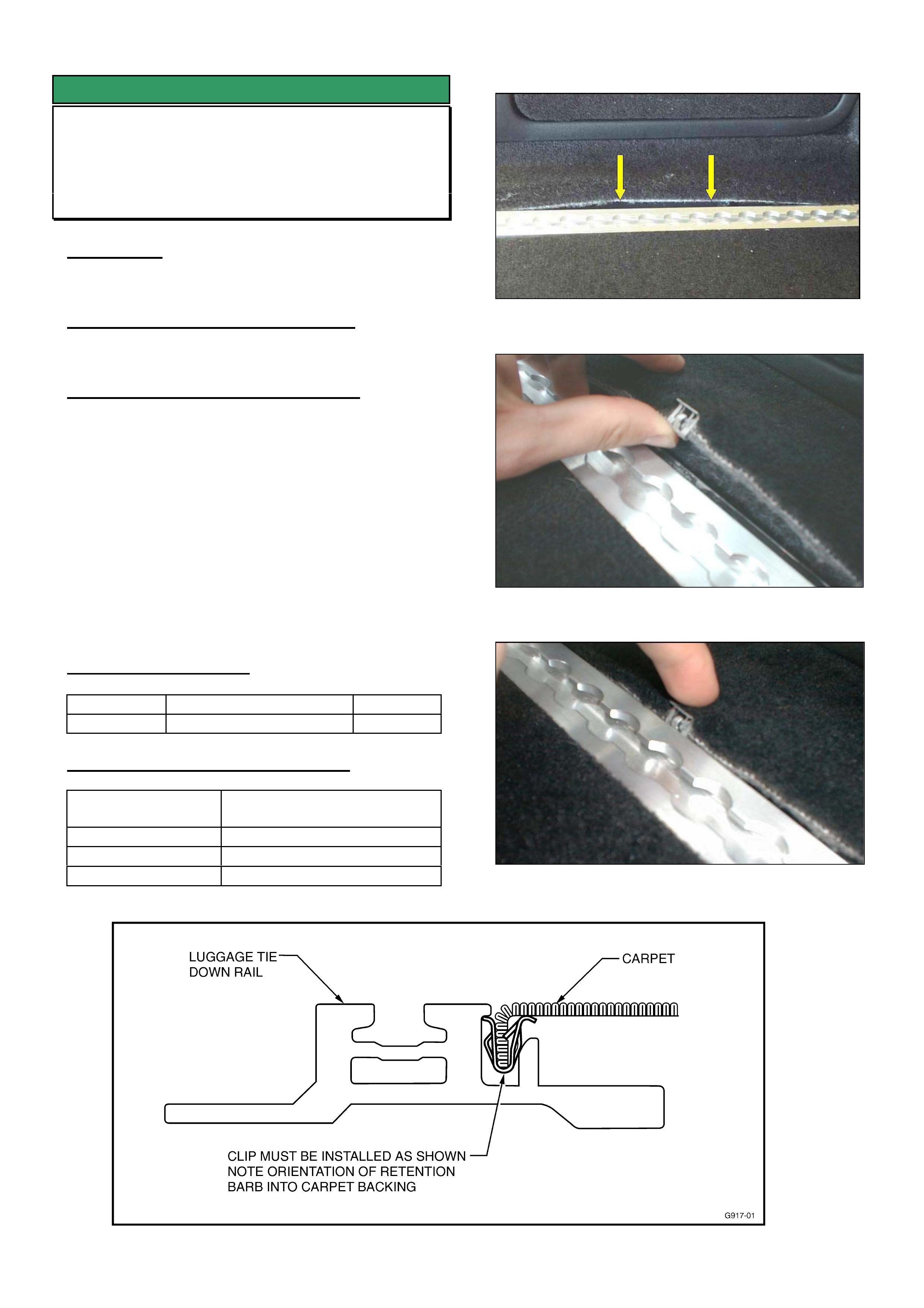
HOLDEN SERVICE TECHLINE _________________________________________________________________AUGUST, 2004
11
SERVICE FIX
Poor Fitment Of Carpet In Load Area
VYII Wagon
GROUP 1 TL0696-0407
CONDITION
Gap between carpet and luggage tie down rail at rear
of load area as shown in Figure 1.
CORRECTION – Vehicle Production
Clips were added to retain carpet to the luggage tie
down rails on all wagons built from 11/6/2004:
CORRECTION – Vehicles In Service
Summary: On vehicles with above condition, fit
retaining clips as per following procedure.
1. Attach clips to carpet at locations shown in Fig 1.
2. IMPORTANT: When attaching clips to the edge of
the carpet as shown in Figure 2, ensure the clip
“barb” digs into the underside of the carpet.
3. Press the clip into the rail as shown in Figure 3.
Ensure the clip locks in under the lip of the rail as
shown in Figure 4.
4. Repeat procedure for other side of load area.
PARTS INFORMATION
Part No.: Description: Qty:
92138869 Clip, Quarter Lower trim Pack of 5
WARRANTY CLAIM INFORMATION
Description Install retaining clips to carpet
in load area - both sides
Labour Op. No. C000523
Time 0.3 hr
Failure Code C0071 Pulled loose
Figure 1. Attach clips at arrows
Figure 2. Firmly push clip onto edge of carpet
Figure 3 Push clip into rail
Figure 4. Sectioned view showing clip installed into load rail

HOLDEN SERVICE TECHLINE _________________________________________________________________AUGUST, 2004
12
DIAGNOSIS HINT
Compressor – Intermittent, Knocking
Noise
V & W Cars
(Group 2) TL0741-0407
Some customers may complain of a knocking noise
from engine bay when slowing down just before
stopping at the traffic lights”. This particular noise is a
normal characteristic of this compressor under high
ambient operating conditions.
On the following two pages is a description of when
and why this knock occurs including internal diagrams
of the variable stroke compressor.
Where appropriate, this information should be
conveyed to customers to reassure them that the
“knock” will not affect compressor performance or
durability.
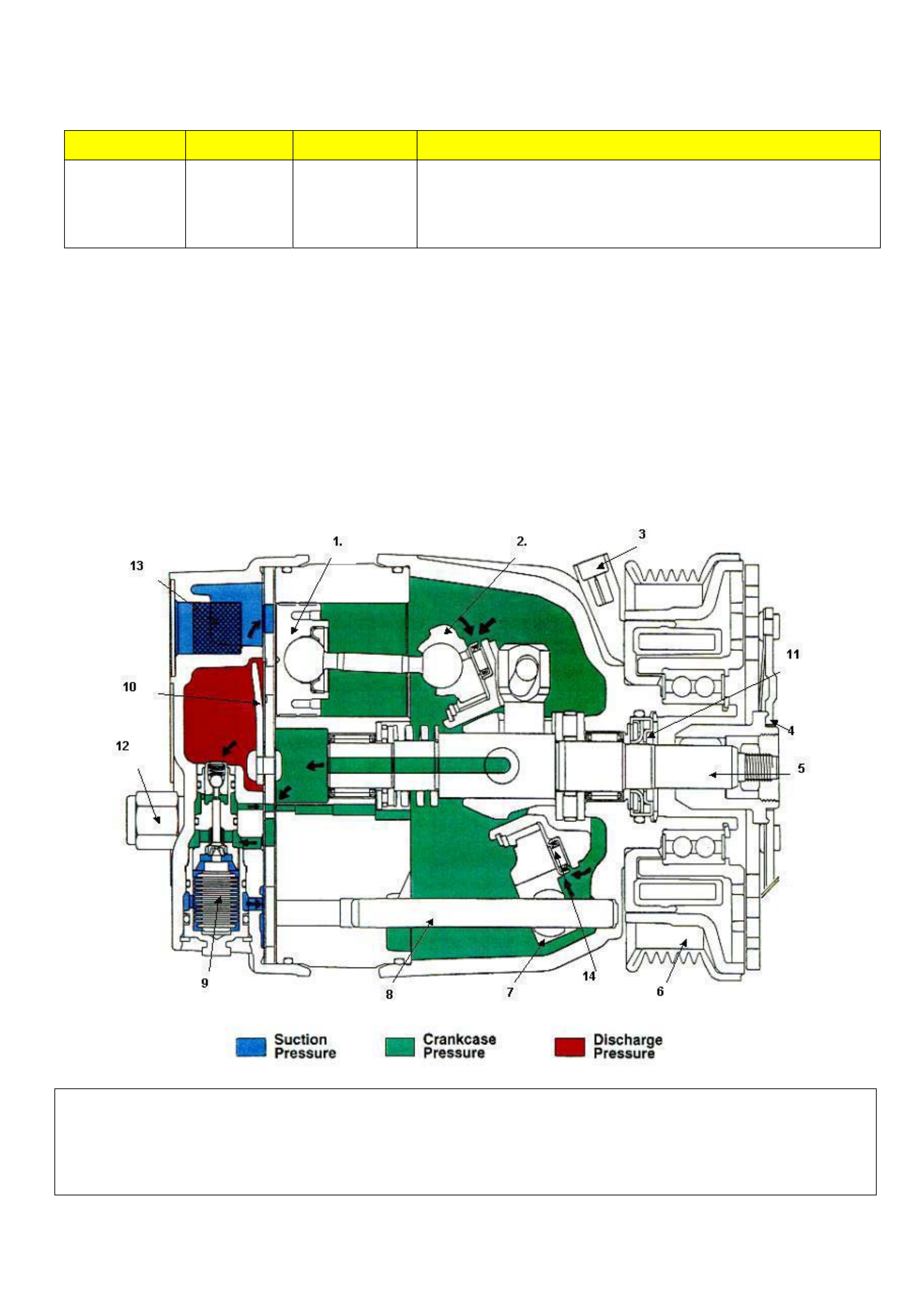
HOLDEN SERVICE TECHLINE _________________________________________________________________AUGUST, 2004
13
NOTE: The following information does not apply if a continuous noise is heard.
SYMPTOM WHEN CONDITION COMMENTS
Intermittent
Knocking noise
Short Duration
(3 Sec or less)
Slowing down.
Stopped at
traffic lights
High Ambient
Temperature.
This is an operational noise experienced on some compressors
when the pumping capacity is self adjusting.
Occurs under unique ambient and system conditions and is not
indicative of internal fault or damage inside compressor
• A typical condition under which the noise is heard is on a hot day when a vehicle slows down or stops (e.g. at
traffic lights), thus reducing the airflow through the condenser. This reduction in airflow increases the demand
on the A/C system to maintain cooling capacity.
• When the load on the A/C system increases the compressor responds by increasing it’s stroke and therefore
refrigerant pumping capacity to maintain system cooling (see image below). During transition to maximum
stroke the wobble plate mechanism slides along the shaft. On some compressors when the stroke increases
very rapidly the wobble plate mechanism can vibrate briefly in response to the pumping action of the pistons
producing the “knocking” noise. The reason the wobble plate mechanism can vibrate is there is a very tight
clearance between the mechanism and the shaft that must be present to allow movement.
• The vibration as described above does not affect the compressor performance or indicate any internal
compressor damage or fault and will not shorten the reliability or durability of the compressor.
1. Piston 2. Wobble plate 3. Field coil connector 4. Front plate 5. Drive shaft
6. Rotor pulley 7. Guide ball 8. Guide pin 9. Control valve 10. Reed valve plate
11. Front seal 12. Pressure relief valve (V8 5.0 Lonly) 13. Mesh strainer (Suction port)
14. Bearing plate 15. Sliding Sleeve.
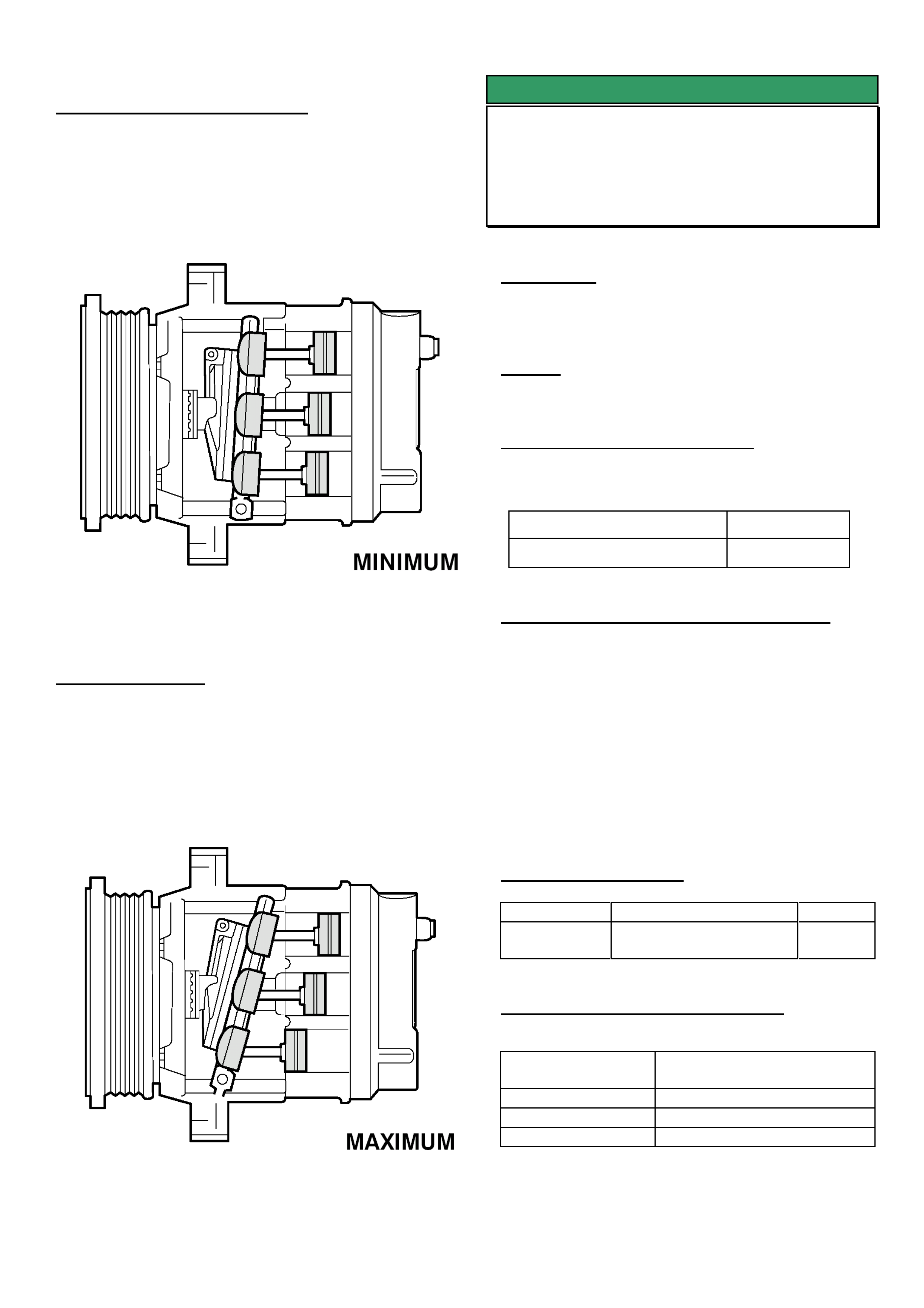
HOLDEN SERVICE TECHLINE _________________________________________________________________AUGUST, 2004
14
Minimum Stroke (destroked)
The Crankcase pressure behind the Pistons is equal to
the pressure in front of the Pistons. Causing the
“Wobble” plate to change it’s angle to almost vertical.
Reducing the stroke of the Pistons and the output off
the Compressor. Approx 0.9 Cubic Inch Capacity
Maximum Stroke
The Crankcase pressure behind the Pistons is less
than the pressure in front of the Pistons. Causing the
“Wobble” plate to change it’s angle . Increasing the
stroke of the Pistons and the output off the
Compressor. Approx 10 Cubic Inch Capacity
SERVICE FIX
Water Leaks Into Rear Load Area
VU, VY Utility - With Hard Tonneau Cover
(Group 1) TL0629-0407
CONDITION
Water leaks into rear load area on some vehicles
when washing vehicle or in heavy rain.
CAUSE
Load area seal design.
CORRECTION – PRODUCTION
Improved seal kits 92147943 have been fitted to all
HSPO hard tonneau cover kits from:
Tonneau Cover Serial No: Built Date:
14967 27/4/04
CORRECTION – VEHICLES IN SERVICE
After confirming that customers vehicle has the
condition as described above, fit a new seal kit part
number 92147943.
Revised fitting instructions “FD1000/22AP04” are
supplied in the kit.
NOTE: Prior to fitting the new seal kit, the old cap
seals and the drain seals must be removed from the
vehicle.
PARTS INFORMATION
Part No.: Description: Qty:
92147943 Load compartment
seal kit
1
WARRANTY CLAIM INFORMATION
Description Replace Load
Compartment Seal Kit
Labour Op. No. R000224
Time 0.7 hours
Failure Code R0042 leaks

HOLDEN SERVICE TECHLINE _________________________________________________________________AUGUST, 2004
15
DIAGNOSIS HINT
Intermittent Remote Key Operation –
DTC 24 (Remote Key Rolling Code Error)
VY, V2 series II & III, WK
(Group 12) TL0744-0407
CONDITION
Customers may advise that, intermittently, their
central locking remote key doesn’t work until the key
is cycled in the ignition.
CAUSE
When a body control module (BCM) has been
replaced under warranty via the change over
program it is more susceptible to setting DTC 24
(Remote Key Rolling Code Error) after an additional
remote key is programmed.
CORRECTION
When presented with a vehicle with the above
condition perform the following steps,
Step 1. Check for DTC 24 in the BCM. If the code
is present or in history, continue with step
2. If DTC 24 has not been set continue
with standard diagnosis as per SIP.
Step 2. Check the vehicle history in the New
Online Warranty system to determine if the
vehicle has been fitted with a change over
BCM.
Step 3. If the vehicle has not been fitted with a
change over BCM continue with standard
diagnosis as per SIP.
If the vehicle has been fitted with a
change over BCM contact Australian
Arrow for additional diagnosis assistance.
Note: Prior to contacting Australian Arrow please
ensure all vehicle remote keys have been
supplied by the customer. Further diagnosis is
not possible without all remote keys.
DIAGNOSIS HINT
Intermittent Remote Key Operation –
External Electrical Interference
All V & W
(Group 12) TL0739-0407
CONDITION
Remote keys and BCM’s are being replaced by
dealers attempting to rectify customer reports of
intermittent operation of the central door locking
system.
Testing of returned components shows that a high
percentage of these parts are not faulty.
CAUSE
High levels of external environmental electrical
interference can potentially cause intermittent
operation of remote key.
The following are examples of generators of external
interferences;
• Telephone transmitter towers
• Television transmitter towers
• Radio transmitter towers
• Multi story and under ground car parks
• Over head and under ground power lines,
transformers or sub stations
• Wireless computer networks
• Electronic dog collars
• Other vehicles central locking remotes
• Remote transmitters (ie: Roller Doors)
• Automatic Doors (ie: Supermarkets,
Hospitals)
• Vehicle access tunnels (ie: Sydney Harbour,
Melbourne City Link)
• Climatic conditions such as rain
Some vehicle accessories or luggage can also cause
interference with remotes keys. The following are
examples of items which are known to have caused
remote operational issues:
• Excess or metallic base window tinting
• Large metallic objects in vehicle (ie: golf
clubs, fire extinguishers)
• Excess keys on key-Ring
• Satellite, digital or analogue mobile phones
• Faulty in-vehicle phone wiring connections
• Aftermarket electronic accessories

HOLDEN SERVICE TECHLINE _________________________________________________________________AUGUST, 2004
16
CORRECTION
Before attempting diagnosis on vehicles for
intermittent operation of the central locking remote
it is important to find out from the customer the
exact operating conditions and location where
the fault occurs so that the root cause of the
problem can be determined.
Remote keys and BCM’s should not be replaced for
customer reports of intermittent operation, unless the
problem can be reproduced and the same problem
does not occur on another vehicle of the same
specification in the same location.
SERVICE PROCEDURE
Cylinder Head Expansion (Welch or Welsh) Plug Replacement Guidelines
V & W carlines V6 and Gen III V8
(Group 6A) TL0733-0407
The following information is repeated from Warranty processing Bulletin 19/04
Please note that Standard Times for replacing expansion plugs are now based on using the following procedures.
V6 / V8 Cylinder Head - Rear Plug
Replacement of the plugs in the rear of the cylinder heads requires removal of the engine/transmission assembly.
V6/V8 Cylinder Head - Front Plug
Replacement of the plugs in the front of the cylinder head can be done in the car.
NOTE The V8 right hand side front plug will require removal of the water pump.
Plug Sealant – Always apply a sealer such as Loctite 242 (or equivalent) around the plug prior to installation.
WARRANTY CLAIM INFORMATION
The following Labour Times information will be included in PV SIP number 6.6.
LAB OP LAB CODE DESCRIPTION STD TIME
J314740 WELSH PLUG, CYL HEAD FRONT - REPLACE CYLS 1,3,5,(7) .5
ADD FOR :GEN III .1
J314750 WELSH PLUG, CYL HEAD FRONT - REPLACE CYLS 2,4,6,(8) .7
ADD FOR :GEN III .7
J314760 WELSH PLUG, CYL HEAD REAR - REPLACE CYLS 1,3,5,(7) 6.5
REMOVE ENGINE & TRANS FOR V6 & GEN III -
ADD FOR: GEN III .3
ADD FOR: AWD 1.0
ADD FOR: A/C .5
J314770 WELSH PLUG, CYL HEAD REAR - REPLACE CYLS 2,4,6,(8) 6.5
REMOVE ENGINE & TRANS FOR V6 & GEN III -
ADD FOR: GEN III .3
ADD FOR: AWD 1.0
ADD FOR: A/C .5
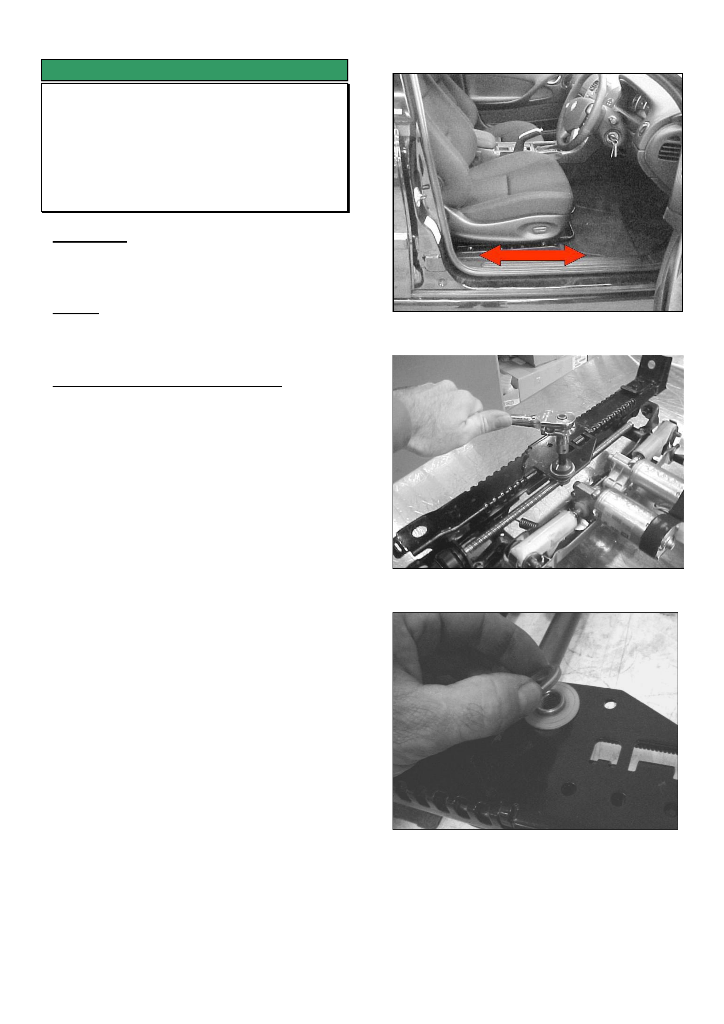
HOLDEN SERVICE TECHLINE _________________________________________________________________AUGUST, 2004
18
SERVICE FIX
Electric Seat - Fore Aft Movement
VT,VX & VY series I - Calais models only
V2 series I & II,
WH, WK up to L162085 (A9W)
(Group 1) TL0699-0407
CONDITION
Fore-aft movement of front seat. Usually most
noticeable under braking when vehicle comes to a
sudden low speed stop.
CAUSE
The lead-screw nut, which is fixed to the lower
section of the seat track, may be loose in its
mounting plate.
CORRECTION – Vehicles In Service
Summary: This condition can be rectified without
replacing the seat track.
After confirming the complaint condition, replace the
steel washer shown in Figure 4. The thicker washer
provides extra compression of the rubber insulators
and thus reduces the amount of movement between
the lead screw nut and the mounting plate.
Confirmation of condition.
To confirm that seat has fore-aft movement, sit in the
seat and attempt to slide the seat backward and
forward as shown in Figure 1. If there is noticeable
travel in the sliding section of the seat, then proceed
as follows.
1. Move the seat adjustment to the mid position
2. Remove the seat track covers and remove the 4
seat mounting bolts.
3. Tip the seat assembly backward and rest against
the rear seat. Ensure that both the seats are
protected against accidental damage.
4. Remove the Lead screw nut retaining bolt (torx
head). Refer Figure 2.
5. Remove existing steel washer (2.5mm) and
replace with washer 92148372 (3.5mm). Refer
Figure 3.
6. Reinstall the retaining torx bolt and torque to 40
to 45 Nm. Refer Figure 4.
7. Repeat for the other seat track.
8. Reposition seat and reinstall the 4 seat mounting
bolts. Tighten to 35 to 50Nm.
9. Reinstall the seat track plastic covers.
10. Repeat procedure for other front seat.
Figure 1. Fore-Aft movement check
Figure 2 Removing lead-screw retaining bolt.
Figure 3. Replace steel washer
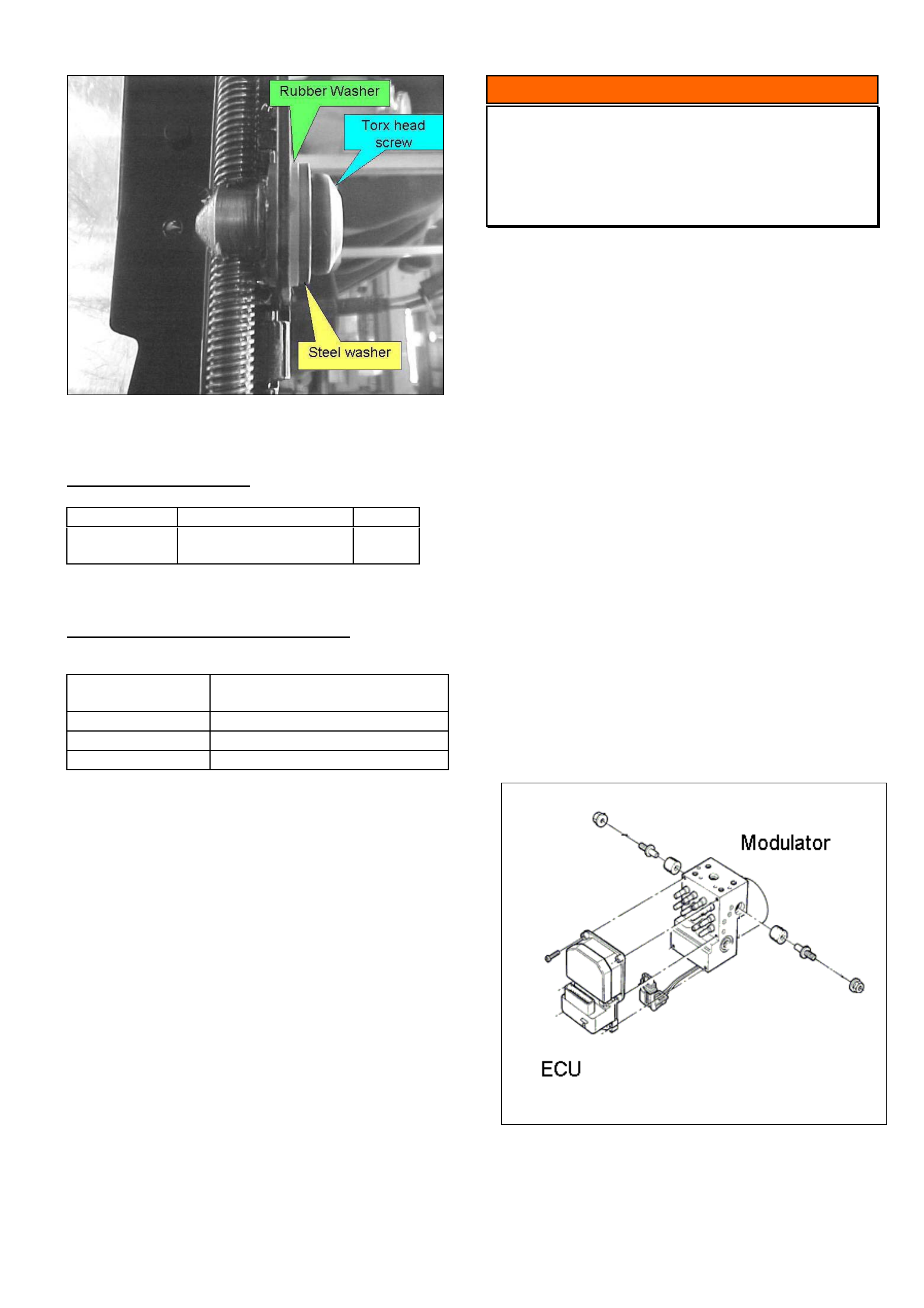
HOLDEN SERVICE TECHLINE _________________________________________________________________AUGUST, 2004
19
Figure 4.
PARTS INFORMATION
Part No.: Description: Qty:
92148372 Seat Fore/Aft Kit
(contains 4 washers)
1
WARRANTY CLAIM INFORMATION
For vehicles covered under warranty.
Description Replace seat track lead screw
nut washers – Both front seats
Labour Op. No. C000526
Time 0.6 hr
Failure Code C0027 loose
INFORMATION
Revised ABS Replacement Guidelines
V & W
(Group 5) TL0567A-0407
This Techline supercedes the previous one in Issue
9, Sep, 2003. All copies of the previous techline
should be marked “Cancelled”. The following
information is also contained in All Dealer Letter
25/2004.
Holden now recommends replacing the ECU
(Electronic Control Unit) component of the ABS
module as a separate part.
Previous policy was to replace the complete ABS
module only during the warranty period.
When diagnosis as per SIP indicates a fault with the
ECU component of the ABS module the ECU can be
removed and replaced from the ABS module.
Although the ECU is a relatively robust unit,
technicians still need to take care and follow correct
procedures in order to avoid ECU damage.
The procedure for ECU replacement is in Passenger
Vehicle SIP.
Service Prior Approval Process (SPAP) is still
required for ABS module or ECU replacement as per
Special Warranty Component Replacement
Requirements in SIP.

HOLDEN SERVICE TECHLINE _________________________________________________________________AUGUST, 2004
20
INFORMATION
Disabling Seat Belt “Audible” Warning
VY, V2 Series 2 & 3, WK – Police use only
Group 12 TL0722-0407
IMPORTANT: The procedure described in this
techline is to be performed on Police vehicles
ONLY when requested by the Police to do so.
----------------------------------------------------------
Before commencing, ensure Tech 2 has software
version 13.101 or greater.
Using Tech2, perform the following selections.
F1: Diagnostics / Model Year / VY Series / F3: Body /
Instrument / F5: Program / F1: Configuration
You will then be presented with the configuration list
similar to the one below.
1.
Scroll down using the arrow key to show the
following screen. You will notice that Seat Belt
Warning is a new addition.
2.
Place the cursor over ‘Seat Belt Warning’ then
select Modify to display the following screen.
3.
Using the arrow keys select OFF, and then select
the Modify key.
Tech 2 will then display the following screen.
4.
Select Program to save the change to the
configuration list.
NOTE: on some instrument clusters you may
notice that the Engine Type is flashing. You will be
required to update this field or programming will
not be successful.
Enabling Seat belt warning
The seat belt warning can be enabled again by
repeating the above procedure and when you
reach screen No. 3, use the arrow keys to select
ON before proceeding.
Configuration
(4) 2004 VY Series
Instrument
Engine Type V6 & V6 SC
Speedometer Pulses 6307
SRS Configuration 4 Loop SRS
Transmission Type Manual
Occupant Climate Control Not Present
Police Mode No
Seat Belt Warning OFF
________________________________1/8____
Engine Type
Abort Modify Program
Please Reselect System !
Configuration
(4) 2004 VY Series
Instrument
Seat Belt Warning
OFF
ON
_
____________________________________1/2____
Abort Modify
Configuration
(4) 2004 VY Series
Instrument
Country Australia / NZ
Engine Type V6 & V6 SC
Speedometer Pulses 6307
SRS Configuration 6 Loop SRS
Transmission Type Manual
Occupant Climate Control Not Present
Police Mode Yes
________________________________1/8____
Country
Abort Modify Program
Configuration
(4) 2004 VY Series
Instrument
Engine Type V6 & V6 SC
Speedometer Pulses 6307
SRS Configuration 6 Loop SRS
Transmission Type Manual
Occupant Climate Control Not Present
Police Mode Yes
Seat Belt Warning On
________________________________1/8____
Engine Type
Abort Modify Program

HOLDEN SERVICE TECHLINE _____________________________________________________________SEPTEMBER, 2004
6
DIAGNOSIS HINT
Loss of Power with No DTC’s set
Opel Engines with Electronically
Controlled Throttles
(GROUP 6C) TL0771-0408
PROBLEM DESCRIPTION
TAS have received calls reporting - “intermittent loss
of power or engine appears to return to idle while
driving”.
Preliminary checks show no stored DTC’s relating to
electronic throttle failure and/or pedal position sensor
(located within accelerator pedal assembly).
In most cases the symptoms can be reproduced,
although no fault can be found relating to these
components or associated wiring.
POSSIBLE CAUSE
On engines with electronic throttles, the status of the
brake pedal switch is monitored by the engine ECU,
and is used to control throttle position.
If, during normal driving or accelerating, the ECU
sees a brake pedal input as being active for a
predetermined period of time, the ECU will command
the throttle to return to idle position until brake pedal
status returns to inactive, or vehicle speed
significantly decreases.
This operating characteristic of the ECU does not
cause any trouble codes to set and has often led to
time consuming misdiagnosis of ECU’s and electronic
throttle components.
SERVICE RECOMMENDATION
If presented with a vehicle fitted with electronic throttle
control with any of the above symptoms:
1. Check the adjustment and sensitivity of the
brake light switch. This can be done using
Tech 2; then selecting Engine - “Data list” and
monitoring brake pedal switch or brake pedal
status.
Adjust brake pedal switch as required.
2. If the brake light switch does not require
adjustment, then the above condition may be
caused by the customers driving technique; i.e.
driving with left foot resting on brake pedal and
right foot on accelerator pedal. This should be
discussed with the customer.
DIAGNOSIS HINT
Cruise Control Inoperative DTC P0567
Opel Models with Z18XE Engine
(GROUP 12) TL0781-0408
PROBLEM DESCRIPTION
Customer may complain that cruise control becomes
Inoperative.
CAUSE
Investigation has found that if the cruise control is set
and the driver holds the decel button to reduce
vehicle speed and simultaneously applies the brake,
DTC P0567 will set in the engine ECU and the cruise
control will become inoperative.
SERVICE RECTIFICATION
This is a function programmed into the engine ECU
as a safety feature. Operator education is required to
provide the driver with an understanding of the
system to prevent further incident.
The DTC will need to be cleared by Tech 2 before
normal operation can be achieved.
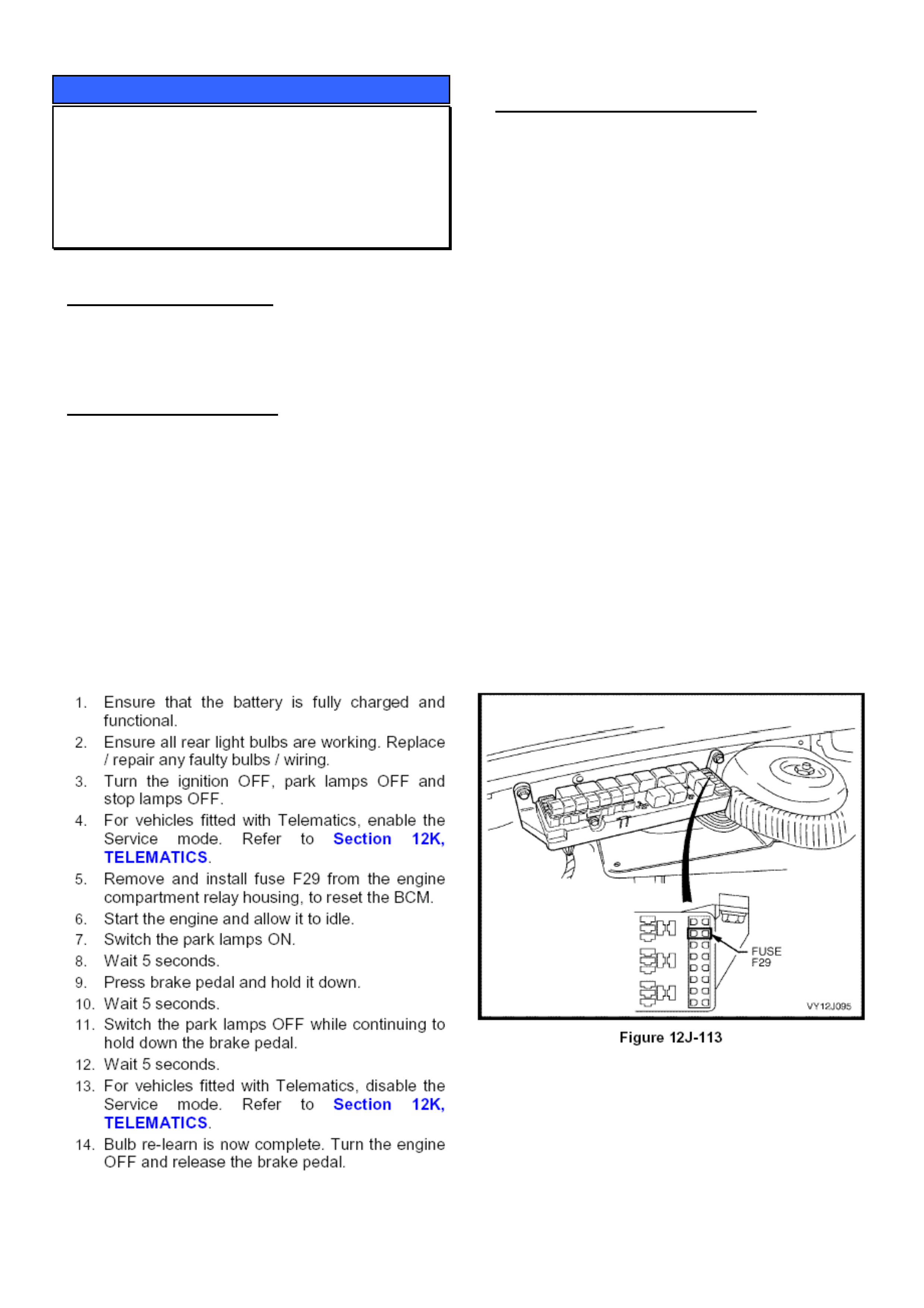
HOLDEN SERVICE TECHLINE _____________________________________________________________SEPTEMBER, 2004
7
SERVICE PROCEDURE
Rear Lamp Failure Warning – Re-learn
Procedure
VY, V2, WK
(GROUP 12) TL0779-0408
PROBLEM DESCRIPTION
Rear lamp failure warning light is showing on dash
when all rear lights are working normally.
SERVICE RECTIFICATION
Technicians are reminded of the requirement to
perform the bulb re-learn procedure after the battery
has been disconnected or the power supply to the
BCM has been removed.
The following bulb relearn procedure is taken from
SIP.
Refer Section 12J – Body Control Module / 4 – BCM
Diagnostics / 4.20 – Rear Lamp failure warning
system
PREVIOUS MODELS REMINDER
All earlier Holden vehicles equipped with a BCM that
has the rear lamp function, also require the bulb re-
learn procedure to be carried out.
For VP / VQ / VR / VS / VT / VX Vehicles please refer
to the relevant sections in SIP or the workshop
manuals.
In SIP this can be found under High series BCM,
Diagnosis section.
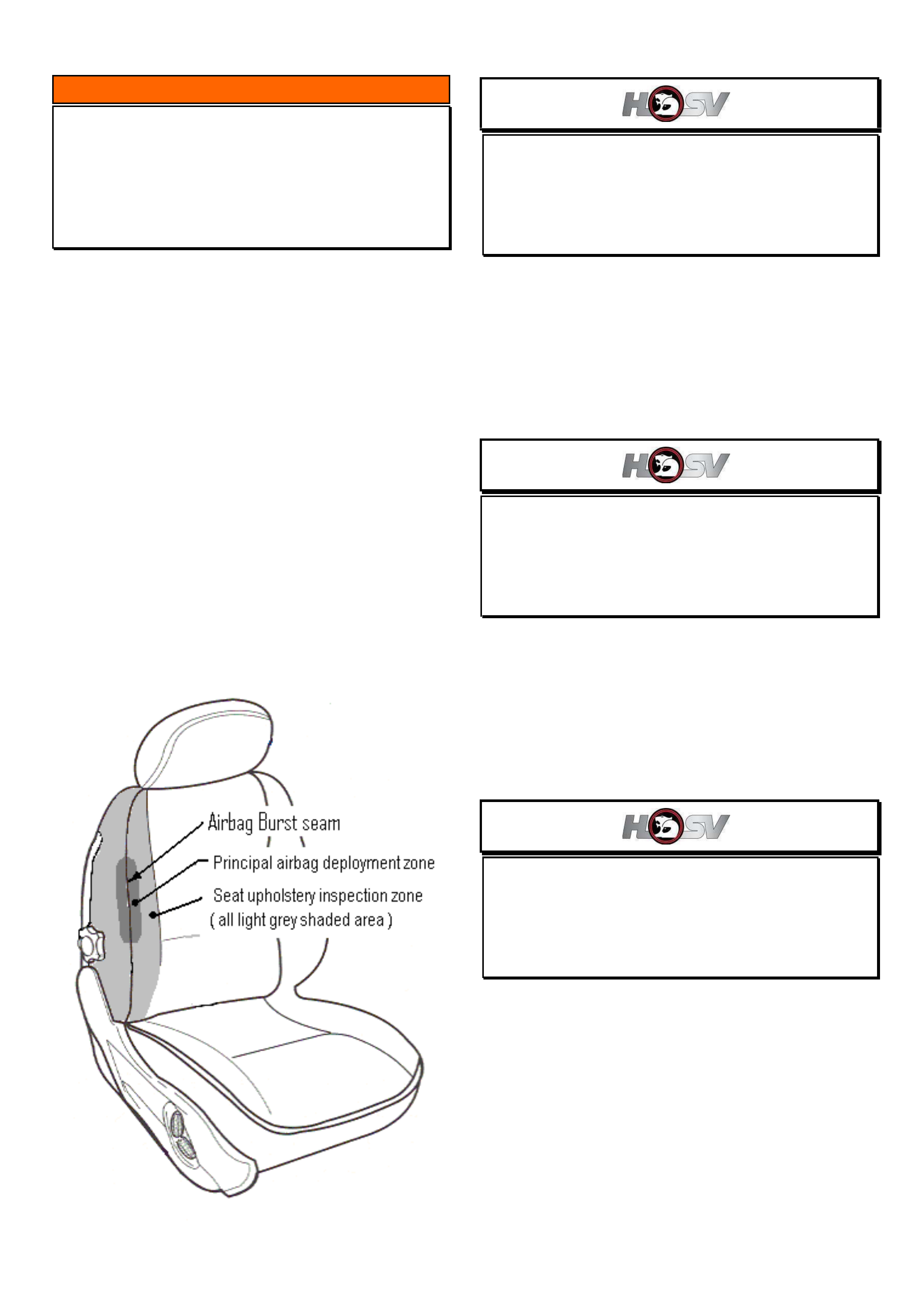
HOLDEN SERVICE TECHLINE _____________________________________________________________SEPTEMBER, 2004
8
INFORMATION
Inspection Of Seat Back Upholstery
All V & W Models with Side Impact
Airbags
(GROUP 1) TL0759-0408
In the event of an airbag deployment, the Side Impact
Airbag uses the “burst seam” (shown in Figure 1) as a
controlled path out of the seat.
Because the “burst seam” together with the seat
cover fabric and seat foam comprise part of the
airbag system, damage to any of these components
may influence the deployment characteristics of the
airbag.
Therefore, any customer vehicle in which the seat
back upholstery is worn/damaged in the area
identified by the light grey shading in Figure 1, should
be inspected thoroughly for evidence of the following:
• Extensive wear through or tearing of fabric
• Loose or broken “burst seam” threads
• Extensive damage to foam pad.
Replace damaged components as required.
NOTE: Superficial scratches and wear on the front
seat plastic backcover will not influence airbag
deployments and does not require rectification.'
Figure 1.
High Intensity Discharge (HID) lights
Various HSV models at VY2 level
(GROUP 12) TL0768-0408
For full technical details on HID lights refer to HSV
Bulletin No. 079/04 which can be viewed on the
Holden Lionheart Portal website. It can be found
under Service Techlines, Year 2004, Group 12 -
Electrical.
Ohlins Suspension
VYII GTS Coupe and sedan
(GROUP 3) TL0769-0408
For a detailed explanation of Ohlins Suspension refer
to HSV Bulletin No. 078/04 which can be viewed on
the Holden Lionheart Portal website. It can be found
under Service Techlines, Year 2004, Group 3 –
Front Suspension.
Tyre Pressure Monitoring System - TPMS
Various HSV models at VYII level
(GROUP 10) TL0761-0408
TPMS stands for Tyre Pressure Monitoring System.
This system monitors Pressure, Temperature and
Pressure deviation. It will warn the driver of an
impending flat tyre or over temperature condition that
may damage tyres.
TPMS has a remote sensor in each wheel that sends
tyre temperature and pressure information via RF
wireless signals to a receiver inside the vehicle.
For a full description of TPMS refer to HSV Bulletin
No. 076/04 which can be viewed on the Holden
Lionheart Portal website. It can be found under
Service Techlines, 2004, Group 10 - Wheels &
Tyres.

HOLDEN SERVICE TECHLINE _____________________________________________________________SEPTEMBER, 2004
12
SERVICE PROCEDURE
A/C Compressor Startup Procedure on
Vehicles Stored For Long Periods
ZC Vectra
(GROUP 2) TL0686-0408
The following information should be passed onto
dealership personnel who are responsible for
retrieving vehicles from the new vehicle storage yard.
CONDITION
There is a possibility of compressor internal damage
occurring on some new vehicles on first start after a
lengthy storage period. e.g. Held in dealer holding
yard for months prior to sale.
SERVICE RECOMMENDATION
The following procedure is recommended when
starting any new ZC Vectra after it has been stored in
a dealer holding yard.
This procedure will help ensure that the compressor
internal moving parts are properly lubricated/bedded-
in prior to being subjected to high speed
engagement.
Procedure
1. Open all instrument panel air outlet vents.
2. Ensure A/C is switched off.
3. Start engine and stabilise idle speed. (approx 5
seconds)
4. Switch HVAC fan to max speed.
5. Switch on A/C and let it run for 5 – 10 minutes
without interruption at engine speed under 1500
rpm.
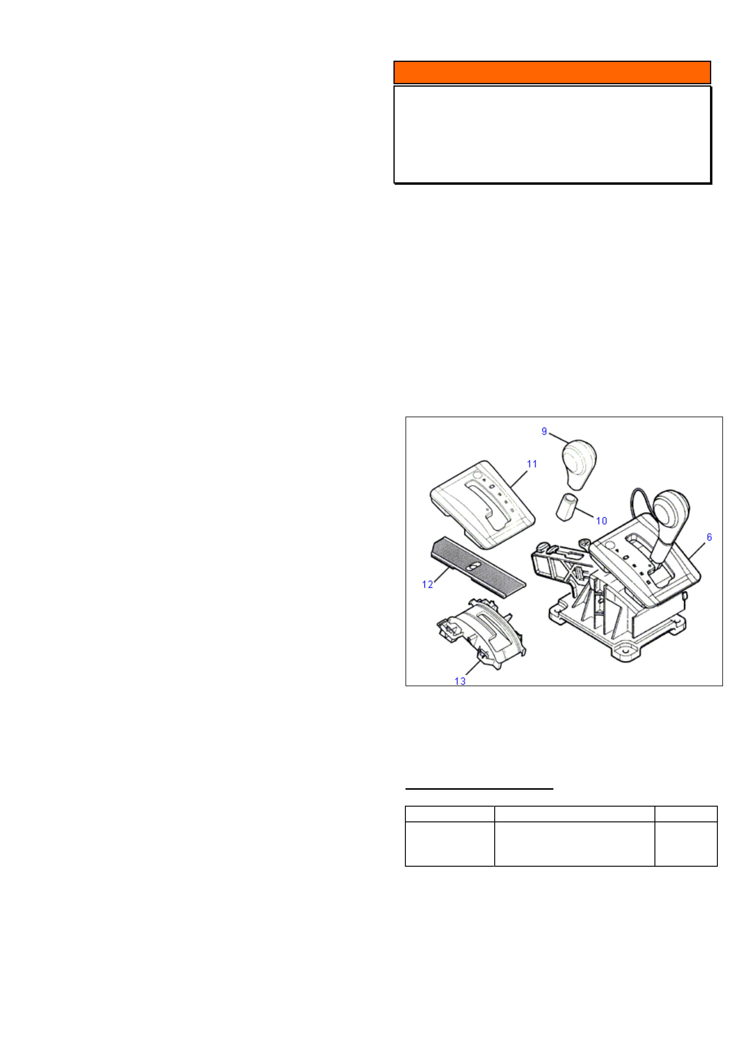
HOLDEN SERVICE TECHLINE _____________________________________________________________SEPTEMBER, 2004
13
INFORMATION
A/T Shifter Slide Replacement Parts
ZC Vectra
(GROUP 7B) TL0561-0408
Holden REPAC still receive complete A/T shifter
assemblies, replaced under warranty, in which only
the convoluted slide component has been damaged.
The convoluted shifter slide (item 12 in Figure 1) is
now available as a replacement part.
From now on, do not replace complete shifter
assemblies when only the slide is damaged.
NOTE: The other components which are also
available as replacement parts are items 9,10,11 &
13 in Figure 1.
Figure 1. Shows A/T shifter assembly (6) and
individually serviced parts 9,10,11,12,13.
PARTS INFORMATION
Part No.: Description: Qty:
93176688 Slider – gear selector
control
(refer item 12 in Figure 1)
1

HOLDEN SERVICE TECHLINE _____________________________________________________________SEPTEMBER, 2004
14
SERVICE FIX
Erratic Fuel Gauge Operation Within the
Full to ¾ Range
VY Ute and Cab Chassis
(GROUP 12) TL0778-0408
CONDITION
Customers advise that their fuel gauge drops from
full within a very short distance or when the gauge is
between full and ¾ it will intermittently return to full
without adding fuel.
CAUSE
Fuel gauge calibration.
CORRECTION – Production
Revised fuel gauge calibration was introduced into
vehicles from the following breakpoint:
ISOVIN: Built Date:
******************L304521 20/07/04
CORRECTION – Service
Use Tech 2 with software version 13.404 (or later)
available on TIS 2000 CD 54 to reprogram the fuel
gauge calibration in the instrument cluster.
Note: When investigating fuel gauge complaints on
any Cab Chassis vehicle ensure that the fuel
pick up hose is not mislocated inside the fuel
tank refer to Techline TL0672 published in
June 2004 page 5.
WARRANTY CLAIM INFORMATION
Refer to PV SIP
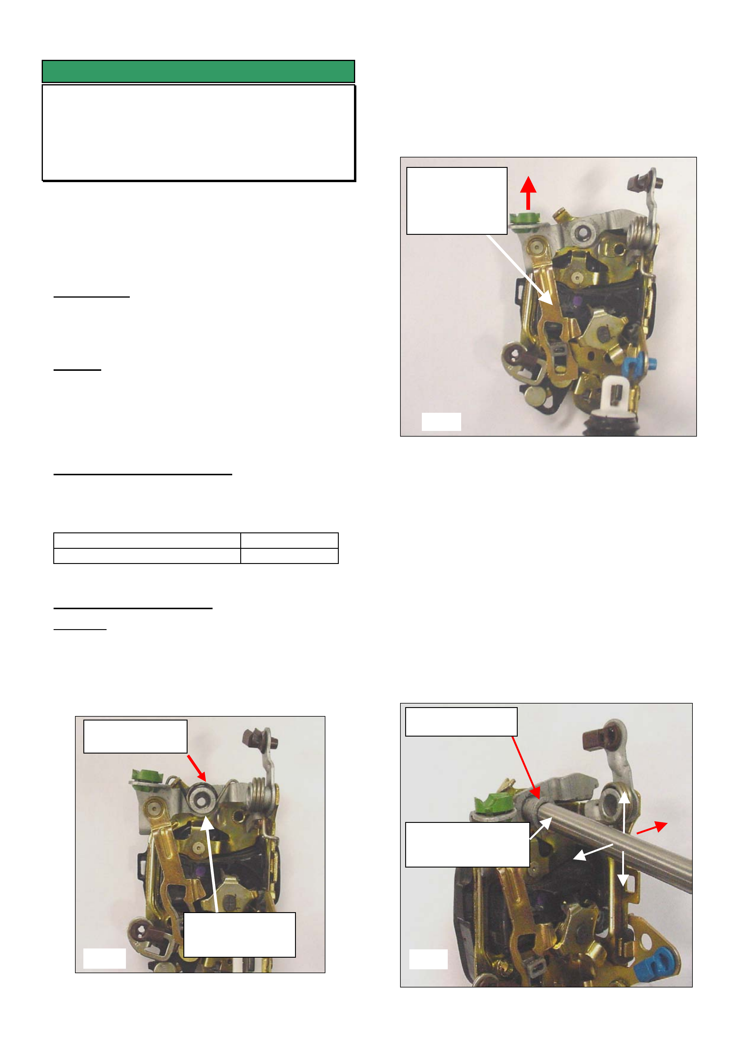
HOLDEN SERVICE TECHLINE _____________________________________________________________SEPTEMBER, 2004
15
SERVICE FIX
Door Lock Malfunction - Revised
VY, WK, V2
(GROUP 1) TL0667A-0408
This techline supersedes the previous article ‘Door
Lock Malfunction’ released in issue 6, 2004 which
recommended replacing the door lock with a new
assembly. This techline issue advises repairing the
lock assembly in lieu of replacing with a new part.
CONDITION
Door lock will intermittently not unlock via remote key
or snib button.
CAUSE
This condition may be caused by binding up of the
latch mechanism due to insufficient operating
clearances at the paddle actuating lever pivot - Refer
fig 1.
CORRECTION – Production
Locks produced with modified operating clearances
within the linkages have been fitted to vehicles from:
ISOVIN: Built Date:
**********L225024 20/01/2004
CORRECTION – Service
Summary: Repair the lock by creating clearance at
the external door handle actuating lever pivot.
1. Remove the door lock from the vehicle and
remove the paddle actuating lever return spring as
shown in figure 1.
2. Check the paddle actuating lever for binding
or sticking as follows: Hold the lock assembly upright
in the “as installed” position then raise the actuating
lever (at red arrow) and release the lever. Check if
the paddle actuating linkage falls under its own
weight.
3. If the linkage DOES fall under its own
weight as per test in step 2, then replace the door
lock assembly.
4. If the linkage DOES NOT fall under its
own weight the paddle actuating lever pivot
needs to be loosened off as per following
procedure
5. Using an 8mm bar or suitable substitute tool
(e.g. pin punch) carefully work the rivet up and down
– left and right continually until the rivet can be
rotated 360o with finger effort; refer figure 3.
Note: When working the rivet, do not permanently
distort the rivet mounting plate. Loosen the rivet only
sufficiently to allow 360o rotation by finger effort.
Paddle Actuating
Return Spring
Linkage
should fall
under its own
weight.
Rotate rivet 360o
Fig 1
Fig 2
Fig 3
Paddle actuating
lever pivot.
8mm diameter bar
or equivalent tool.

HOLDEN SERVICE TECHLINE _____________________________________________________________SEPTEMBER, 2004
16
6. Install the return spring (lubrication is not
required)
7. Check that the linkage has correct
movement and does not catch on any other
components.
8. Install the lock assembly to the door (Torque
screws to 3-5 NM)
9. Ensure the inner door trim water seal is
sealed correctly to prevent any water leaks.
10. Check the operation of the door lock (manual
and remote), interior and exterior door handles.
WARRANTY CLAIM INFORMATION
Refer PV SIP if new lock assembly was fitted.
Refer table below if lock was repaired.
Lock
location
Labour Operation Time Allowed
RHF C000529 0.8 Hr
LHF C000532 0.8 Hr
RHR C000535 0.6 Hr
LHR C000538 0.6 Hr

HOLDEN SERVICE TECHLINE _____________________________________________________________OCTOBER, 2004
6
INFORMATION
Change To Electric Mirror Operation
ZC Vectra
(GROUP 12) TL0780-0409
A new feature has been added to the electric mirror
operation on above model from the start of 2004.
Now, whenever the drivers mirror is adjusted Up or
Down, the passenger mirror will automatically adjust
Up or Down to suit.
This change was introduced on ZC models from:
ISOVIN: Built Date:
W0L0ZCF6848050018 27 Jan 2004
(This “built date” is normally shown on a label attached
to the top of the strut tower.)
DIAGNOSIS HINT
Clicking noise from front wheels
YG Cruze
GROUP 10 TL0791-0409
PROBLEM DESCRIPTION
Clicking noise from front wheels when turning. It may
sound like a clicking drive shaft or front wheel bearing.
DIAGNOSIS HINT
Recent investigation has shown that on YG Cruze
vehicles the above condition can be caused by over-
tightened wheel nuts.
Therefore, the first step in diagnosing this condition
should be to verify that the wheel nuts are tightened
using a HAND HELD TENSION WRENCH and
torqued to the spec of 85 Nm (63 lbf-ft) as specified in
LCRV SIP.
NOTE: If the complaint vehicle is built before
23/01/2003, VIN - JSAGHY81S00111647, the front
wheel bearings should be replaced as recommended
in the June 2003 Techline. Refer to techline for more
details.
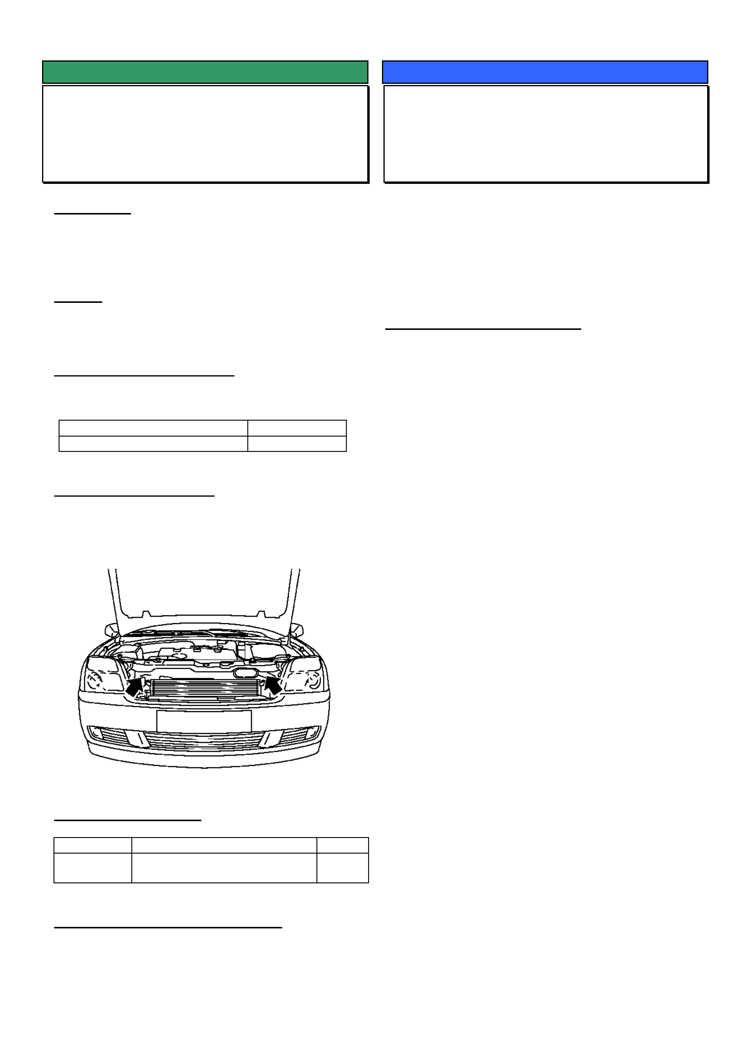
HOLDEN SERVICE TECHLINE _____________________________________________________________OCTOBER, 2004
8
SERVICE FIX
Radiator – Rattling Creaking noise
ZC Vectra
(GROUP 6K) TL0766-0409
CONDITION
Noise heard in passenger compartment when driving
on uneven road or driving off from rest. Can be
mistaken for front suspension noise.
CAUSE
Upper radiator pins/bumpers creak during relative
movement between components.
CORRECTION – Production
Revised radiator upper bumpers have been fitted to
vehicles from:
ISOVIN: Built Date:
W0L0ZCF3541135295 30/6/2004
CORRECTION – Service
In cases of customer complaint, replace the two
radiator upper bumpers with new parts as listed below.
Refer to TIS 2000 for replacement procedure.
PARTS INFORMATION
Part No.: Description: Qty
13186475 Bumper - radiator to front
panel upper
2
WARRANTY CLAIM INFORMATION
Use Labour Times information in Warranty Information
section of current PV SIP CD
SERVICE PROCEDURE
ECU Replacement Procedure
All OPEL Products
GROUP 6C TL0793-0409
TAS receive a high number of calls from technicians
unsure of the correct procedure to use when replacing
an ECU on OPEL products.
The following, is a step by step procedure that must be
used whenever replacing an ECU on OPEL products.
REPLACEMENT PROCEDURE
1. Obtain the security number before starting.
2. Reset the original ECU with Tech 2 as follows:
1. F0 Diagnosis
2. F3 Body / immobiliser
3. F3 Additional Functions
4. F2 Reset Engine Control Unit
5. Enter Security Code
6. Press OKAY if correct security code has been
entered
7. The following warning will appear: “Warning
Engine will not start after reset”
8. Programming Completed.
3. Remove original ECU and install the new ECU.
1. F1 Service Programming system (SPS)
2. F0 Request Info. When finished, disconnect
Tech 2 from vehicle and go to your PC that has
TIS installed. Select Service Programming
System and download the new calibration for
that vehicle. Return to the vehicle and download
the new calibration into the new ECU.
3. To link the new ECU to the vehicle proceed as
follows:
4. F0 Diagnosis.
5. F3 Body / Immobiliser.
6. F4 Programming
7. F0 Program Immobiliser Function
8. Get programming approval from TIS. Once
approval has been obtained, return to
programming immobiliser function.
9. Enter the correct Engine type
10. Engine controller installed.
11. Perform the CAN and VARIANT configuration,
in ECU programming menu.
12. Follow the remaining Tech 2 instructions
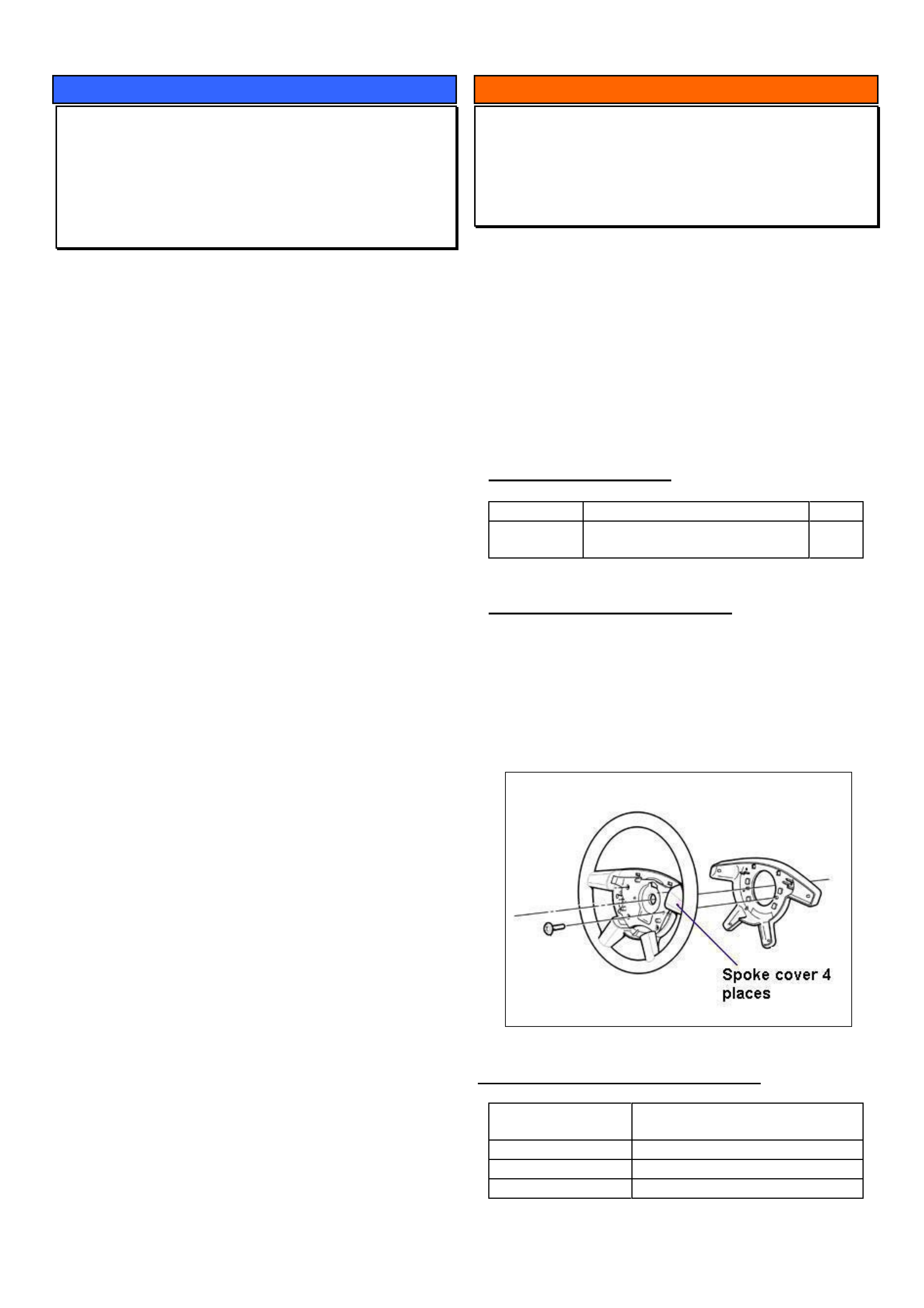
HOLDEN SERVICE TECHLINE _____________________________________________________________OCTOBER, 2004
9
SERVICE PROCEDURE
ECU Programming Precaution
All Opel engines with Electronic Throttle
Control
GROUP 6C TL0795-0409
After using Tech 2 to reprogram an existing ECU or
program a new ECU the following MUST BE
ADHERED TO as the final step in the procedure.
1. Key Ignition OFF for 10+ seconds;
2. Key Ignition ON (engine NOT started) for an
additional 10+ seconds.
3. Start engine.
These steps allow sufficient time for the Electronic
Throttle Control to perform self-tests and relearn its
default positions.
If the above procedure is not adhered to, the following
may occur:
• Setting of DTC’s relating to the Electronic
Throttle Control.
• Driveability issues
• Engine may not start.
To rectify the above conditions, the following
procedure must be performed.
1. Key Ignition OFF for 10+ seconds.
2. Key Ignition ON (engine NOT started) for an
additional 10+ seconds.
3. Connect Tech 2
4. Clear all DTC’s stored in ECU and TCM.
INFORMATION
Steering Wheel Painted Spoke Covers
VY, WK
(GROUP 9) TL0724-0409
The purpose of this techline is to advise that the
painted steering wheel spoke covers are now
available as a replacement kit.
Previously, only the satin chrome spoke covers were
available as replacement parts; Refer Techline No.
TL0655-0403 published in Issue 3, April 2004. The
replacement procedure and warranty information is
identical and is repeated below for information.
PARTS INFORMATION
Part No.: Description: Qty
92148830 Cover package steering wheel
spokes (dark tempest)
1
REPLACEMENT PROCEDURE
1. Remove steering wheel as per PV SIP procedure.
2. Detach rear cover from steering wheel.
3. Remove four spoke covers by undoing attaching
screws from rear.
4. Install new spoke covers.
5. Reinstall all parts.
WARRANTY CLAIM INFORMATION
Description Replace steering wheel
spoke covers
Labour Op. No. C000514
Time 0.5 hr
Failure Code 23 - Finish comes off
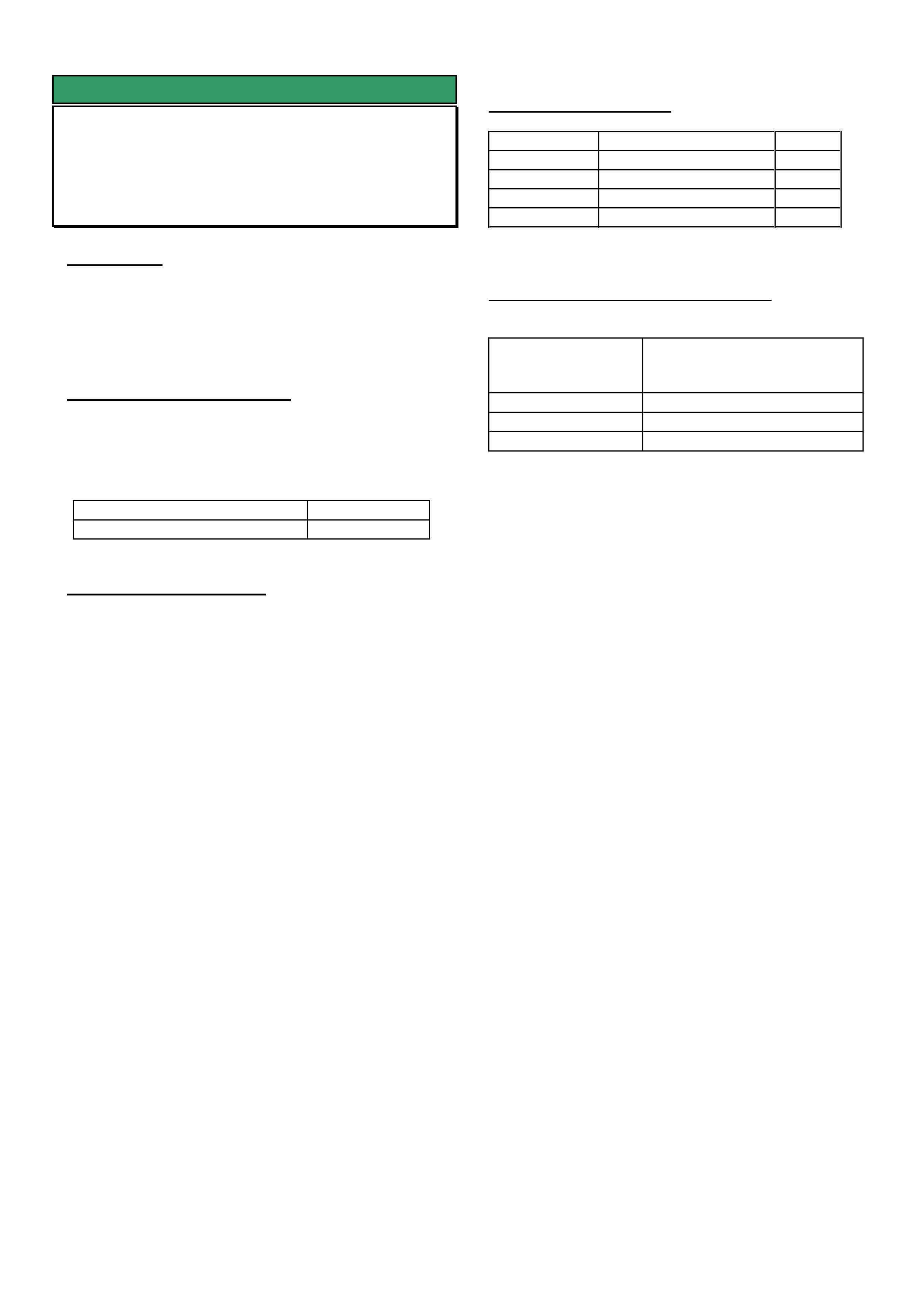
HOLDEN SERVICE TECHLINE _____________________________________________________________OCTOBER, 2004
10
SERVICE FIX
Diff Whine 80 – 100 km/hr
VY Crewman V8 Auto - excluding Cross 8
GROUP 4 TL0631-0409
CONDITION
Some vehicles may experience an unacceptable
“whine” noise from the differential at approximately 80 -
100 km/h at light to medium throttle cruising.
This noise should not be confused with noises
resulting from possible faulty diff bearings or gears.
CORRECTION – Production
Two countermeasures introduced into production are:
• revised (lower) durometer rubber bush in the
front eye of the leaf spring.
• revised (2 spoke) pinion flange.
ISOVIN: Built Date:
**********L218227 9/3/2004
CORRECTION – Service
Summary: After verifying that vehicle has condition as
described above, fit a new diff companion flange and
revised bushes in front eye of rear springs.
Procedure.
(For specific procedures not covered in detail refer to
current PV SIP.)
1. Remove rear springs.
2. Press out existing front eye bush from each spring.
3. Press in new eye bush 92148815.
4. Reinstall spring assemblies.
NOTE: There are four large washers p/n
76543210 that need to be fitted – one on each side
of the front spring eye bush as spacers/locators.
These washers are only fitted to vehicles with the
revised spring eye bushes (so any future removal
of springs should be done carefully – to ensure
that any washers fitted in these locations are
replaced).
5. The revised pinion flange 92176653 should be
fitted with the new nut 92146565 exactly as per
procedure found in PV SIP.
Section 4B – Final Drive & Drive Shafts
2. Minor Service Operations
2.11 Pinion Flange / Replace using old seal.
6. The alternative to step 5 is to have a sublet
repairer (diff specialist) fit the flange. – any such
repairer must use a torque reading tension wrench
to ensure the pre-load before and after are the
same, otherwise, preload related noise/failure may
occur at a later date.
PARTS INFORMATION
Part No.: Description: Qty:
92148815 Bush Rr Spring Front 2
76543210 Washer, Rear 4
92176653 pinion flange
92146565 Flange nut 1
WARRANTY CLAIM INFORMATION
Description Replace bush, leaf spring
front eye – both sides and
replace diff pinion flange
Labour Op. No. F000197
Time 2.1 hr
Failure Code F0040 noisy
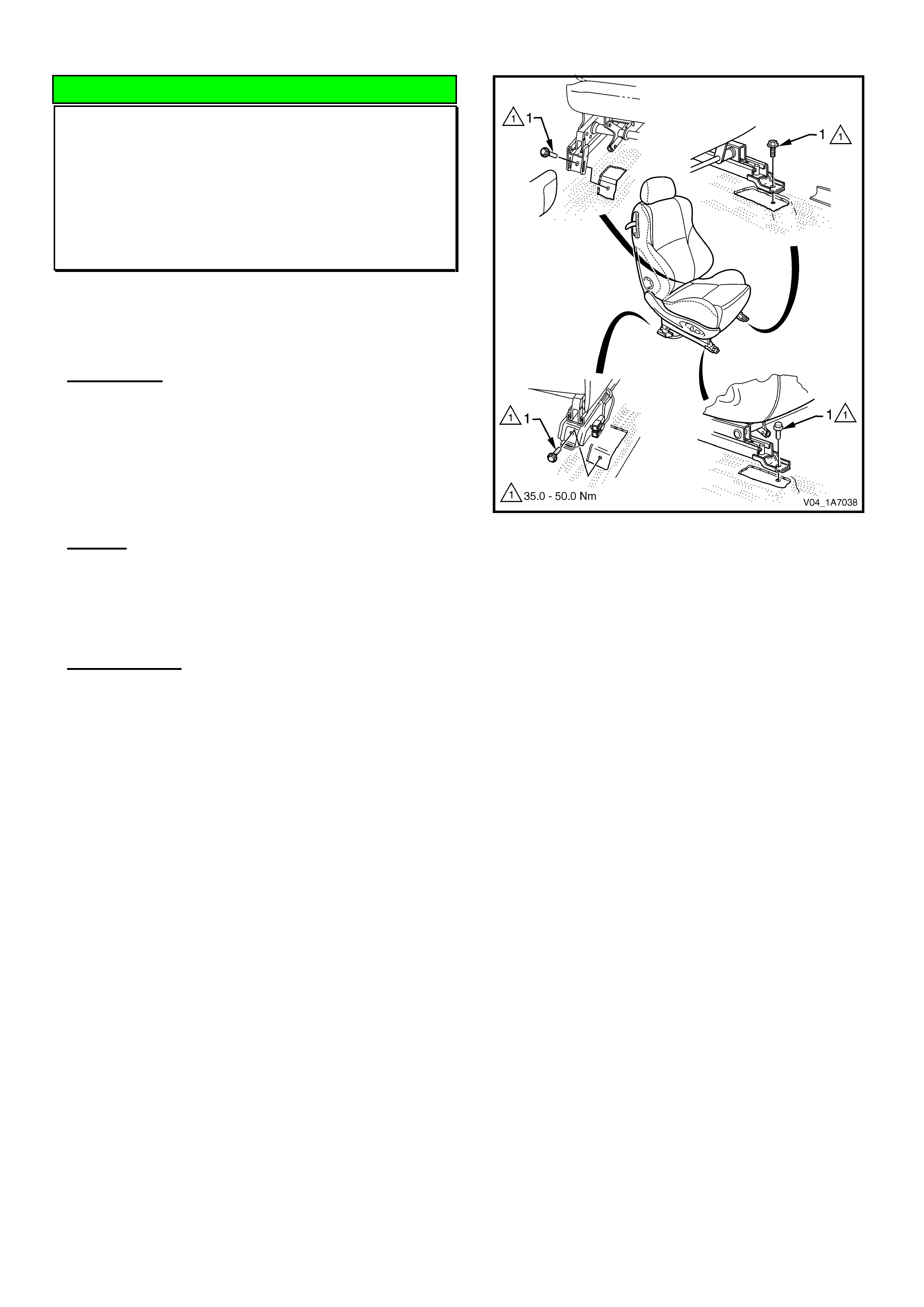
HOLDEN SERVICE TECHLINE _____________________________________________________________OCTOBER, 2004
11
DIAGNOSIS HINT
Seat Track - Excessive Fore/Aft Movement
or “Loose”
V & W with 2 Way and 4 Way Seat Track
Only
(GROUP 1) TL0735-0409
The following applies only to vehicles built after
April 2003.
CONDITION
Symptoms may include:
• Seat track has slight movement under acceleration
and braking.
• Seat stiff to move fore/aft.
CAUSE
The seat track runners may have been slightly
misaligned when the seat was installed in vehicle
assembly.
CORRECTION
1. Remove seat track trims to gain access to all
seat-track-to-floor attaching bolts.
2. Loosen all seat-track-to-floor mounting bolts
(Do not remove the bolts).
3. While sitting in the seat, move the seat to the
mid position, where all bolts can be accessed
without moving the seat, and ensure both track
latches are engaged.
4. Without moving the seat, tighten bolts to 35-
50 Nm in the following sequence. (Refer figure 1).
1. Rear Inboard,
2. Front inboard,
3. Front Outboard,
4. Rear Outboard.
Important: The seat must always be latched
completely and correctly when tightening the
mounting bolts.
5. Check that carpet has not been caught
between the seat track and floor panel at all
mounts positions.
6. Check for elimination of the symptoms.
Figure 1
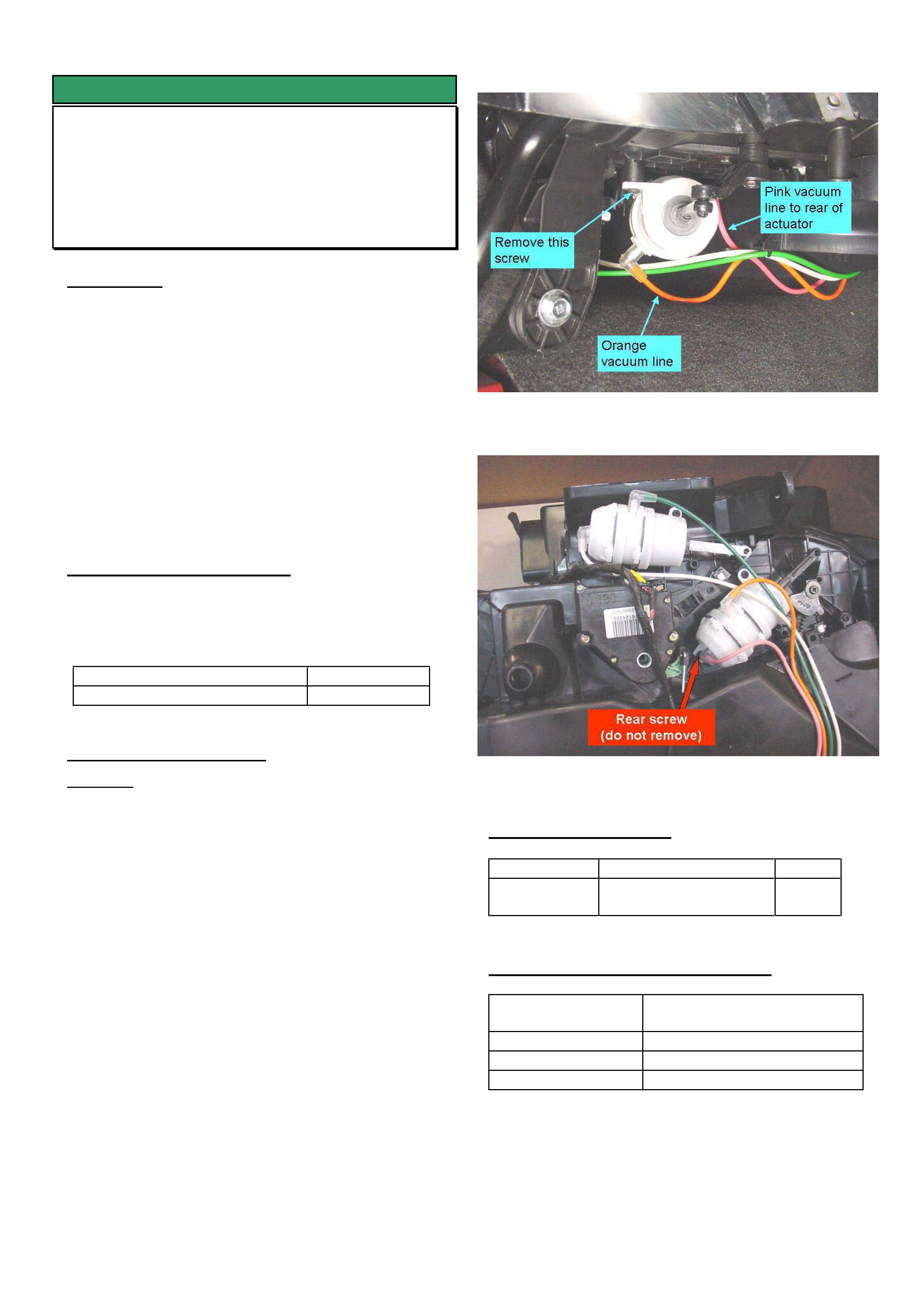
HOLDEN SERVICE TECHLINE _____________________________________________________________OCTOBER, 2004
12
SERVICE FIX
Fluttering Noise From HVAC on High Fan
Speed
VYII, WK
GROUP 2 TL0787-0409
CONDITION
A fluttering noise (like helicopter rotor noise) may be
evident on some VY series 2 vehicles coming from the
HVAC assembly.
This noise, if present, will occur when HVAC control
mode is on highest blower fan speed, “blend mode”
(demist/floor), either hot /cold temperature setting and
vehicle at idle.
The noise is caused by the floor mode door vibrating in
it’s stop position. If you hold the demist door
linkage/gear under the HVAC case drivers side, you
will also note that these also vibrate when the noise
occurs.
CORRECTION – Production
HVAC units with floor actuators the same as the face
actuator (92140681) have been fitted to all models
from:
ISOVIN: Built Date:
**********L318160 11 AUG 2004
CORRECTION – Service
Summary: Replace the floor mode actuator (black
coloured actuating rod) with a face mode actuator
(white coloured actuator rod).
Procedure:
1. Remove the fuse panel cover from below the
steering column.
2. Remove the drivers side centre-console side
cover.
3. From under the HVAC assembly, locate the floor
vacuum actuator as shown in figure 1.
4. Remove the pink and orange vacuum lines from
actuator.
5. Remove the actuator mounting screw shown in
Figure 1.
6. Disconnect the actuator rod from the demist lever.
7. Carefully pull on the vacuum actuator to withdraw it
from the rear attaching screw. (This is made
possible due to the forked rear mounting) Do not
loosen or remove the rear attaching screw.
8. Install new vacuum actuator 92140681 in the
reverse order to removal.
Figure 1. Shows floor actuator to be replaced.
Figure 2. Shows underneath view of HVAC unit
PARTS INFORMATION
Part No.: Description: Qty:
92140681 Vacuum actuator
1
WARRANTY CLAIM INFORMATION
Description Replace floor/demist
vacuum actuator
Labour Op. No. D021420
Time 0.6 hr
Failure Code 40 noisy
IMPORTANT: The time shown in SIP (4.2hrs) against
labour operation No. D021420 for replacing the floor
actuator no longer applies. That time was based on
removing the HVAC unit from the vehicle as specified
in SIP. That procedure is now superseded by the
procedure shown in this techline.

HOLDEN SERVICE TECHLINE _____________________________________________________________OCTOBER, 2004
13
SERVICE FIX
Welch Plug Leaks
Gen III V8 Engine
GROUP 6A TL0777-0409
CONDITION
Suspected coolant leak from the cylinder head welch
plugs.
CORRECTION – Service
Summary: Confirm if stain or actual leak. If leaking,
add cooling system pellets to seal leaks. If pellets are
unsuccessful then replace welch plugs.
Inspection:
If there is evidence of a coolant leak at the cylinder
head welch plugs, the area should be cleaned and
inspected to determine if an actual leak is present or if
it is only a coolant stain.
Coolant Stain:
At the engine manufacturing plant, some engines are
built with cooling system sealing pellets to ensure
complete sealing of the welch plugs. A small amount
of seepage (which causes the staining) may occur
during the first 15 minutes of operation before the
coolant pellets dissolve and seal the plug to cylinder
head area.
Coolant leak:
If an actual leak is present, the cooling system should
be partially drained (say 2-3 litres) then refilled with the
addition of 2 crushed sealing pellets (part number
92140053) added to the coolant mixture. Refer to SIP
procedure 6B3 - 2.3 for refilling procedure.
NOTE 1. There are 3 pellets in the packet but only 2
are required per engine.
NOTE 2. Although SIP states not to use sealing pellets
with extended life antifreeze coolant (conforming to
GM6277M), the use of sealing pellets part number
92140053 is acceptable.
After filling the cooling system, the engine should be
operated for at least 15 minutes before inspecting for
leaks again.
If the welch plugs continue to leak after installing the
sealer pellets, new welch plugs should be installed as
follows.
NOTE 3. Please PIR all cases where sealer pellets
were not successful in stopping leaks.
NOTE 4. To replace plugs in the rear of the cylinder
heads, first remove the engine/transmission assembly.
1. Lower the coolant level so there is no coolant in the
cylinder heads.
2. Remove the cup welch plugs and clean the bores.
3. Apply Primer N (Loctite product number 7649) to the
new plug.
4. Apply Loctite 620 adhesive to the welch plug bore in
the cylinder head.
By applying adhesive and accelerator to the seperate
components, you avoid any cross contamination. This
will avoid any potential pre-curing of adhesive that is
applied to an activated surface.
5. The vehicle should be allowed to sit for a minimum
of 1 hour prior to refilling with coolant and retesting
engine for leaks.
NOTE: The above commercial products have been
found to be suitable for use in this repair procedure.
Other equivalent products may be used in their place.
PARTS INFORMATION
Part No.: Description: Qty:
92140053 Sealing pellets
(pack of 3)
1
WARRANTY CLAIM INFORMATION
Refer to Warranty Claim Information in latest PV SIP
(6.6 onwards).
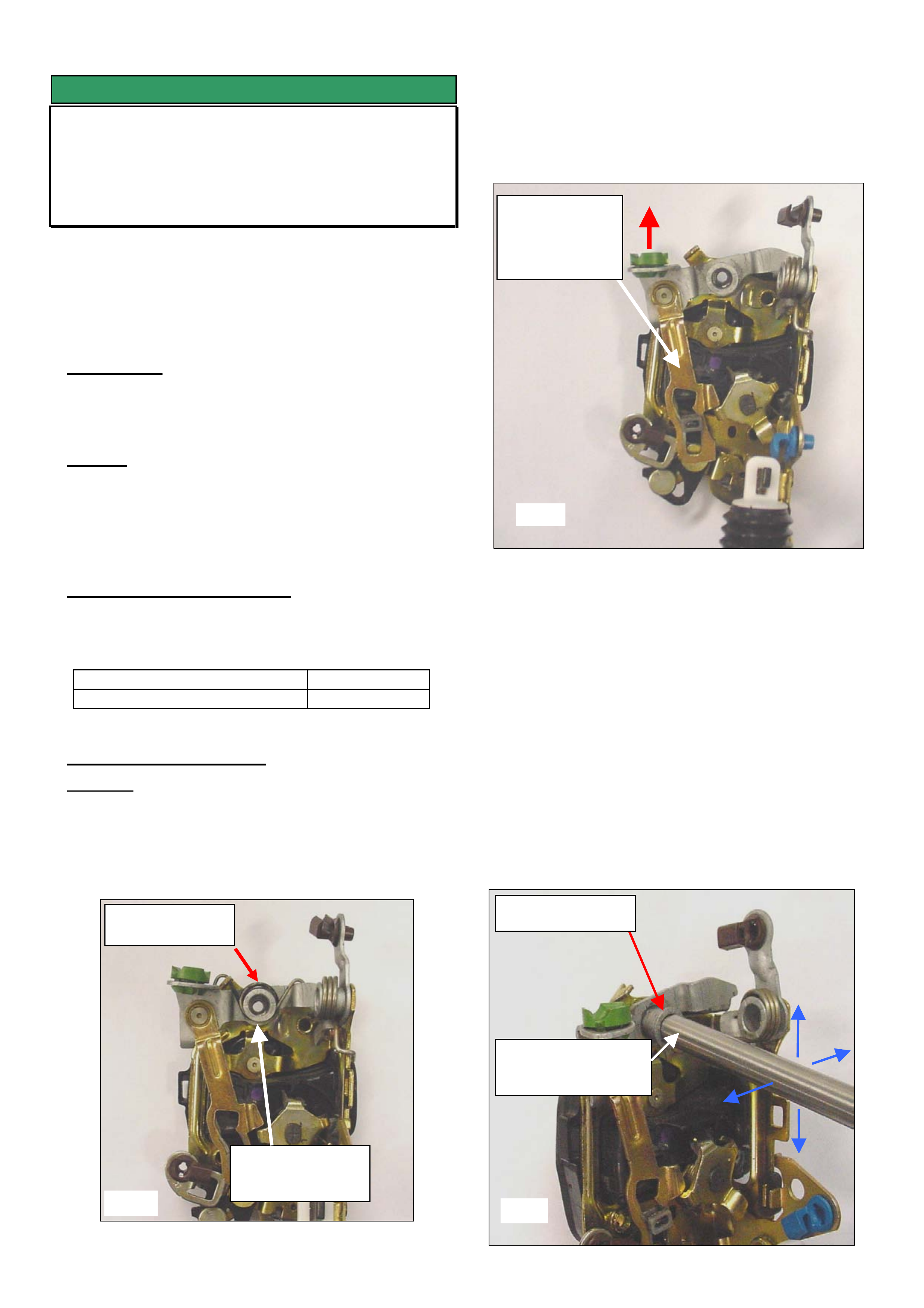
HOLDEN SERVICE TECHLINE _____________________________________________________________OCTOBER, 2004
14
SERVICE FIX
Front Door Lock Malfunction
VY, WK, V2
(GROUP 1) TL0667B-0409
This techline supersedes the previous one in issue 8,
2004. It is revised by making the repair procedure only
applicable to front door locks and rewording step 3 of
procedure. Please mark all previous copies as
superseded.
CONDITION
Front door lock(s) will intermittently not unlock via
remote key or snib button.
CAUSE
This condition may be caused by binding up of the
latch mechanism due to insufficient operating
clearances at the paddle actuating lever pivot - Refer
fig 1.
CORRECTION – Production
Locks produced with modified operating clearances
within the linkages have been fitted to vehicles from:
ISOVIN: Built Date:
**********L225024 20/01/2004
CORRECTION – Service
Summary: Repair the lock by creating clearance at the
external door handle actuating lever pivot.
1. Remove the door lock from the vehicle and
remove the paddle actuating lever return spring as
shown in figure 1.
2. Check the paddle actuating lever for binding or
sticking as follows: Hold the lock assembly upright in
the “as installed” position then raise the actuating lever
(at red arrow) and release the lever. Check if the
paddle actuating linkage falls under its own weight.
3. If the linkage falls under its own weight as per
test in step 2, do not perform step 5. Further diagnosis
for the lock intermittently not unlocking is required.
4. If the linkage DOES NOT fall under its own
weight the paddle actuating lever pivot needs to be
loosened off as per following procedure
5. Using an 8mm bar or suitable substitute tool
(e.g. pin punch) carefully work the rivet up and down –
left and right continually until the rivet can be rotated
360o with finger effort; refer figure 3.
Note: When working the rivet, do not permanently
distort the rivet mounting plate. Loosen the rivet only
sufficiently to allow 360o rotation by finger effort.
Paddle Actuating
Return Spring
Linkage
should fall
under its own
weight.
Rotate rivet 360o
Fig 1
Fig 2
Fig 3
Paddle actuating
lever pivot.
8mm diameter bar
or equivalent tool.
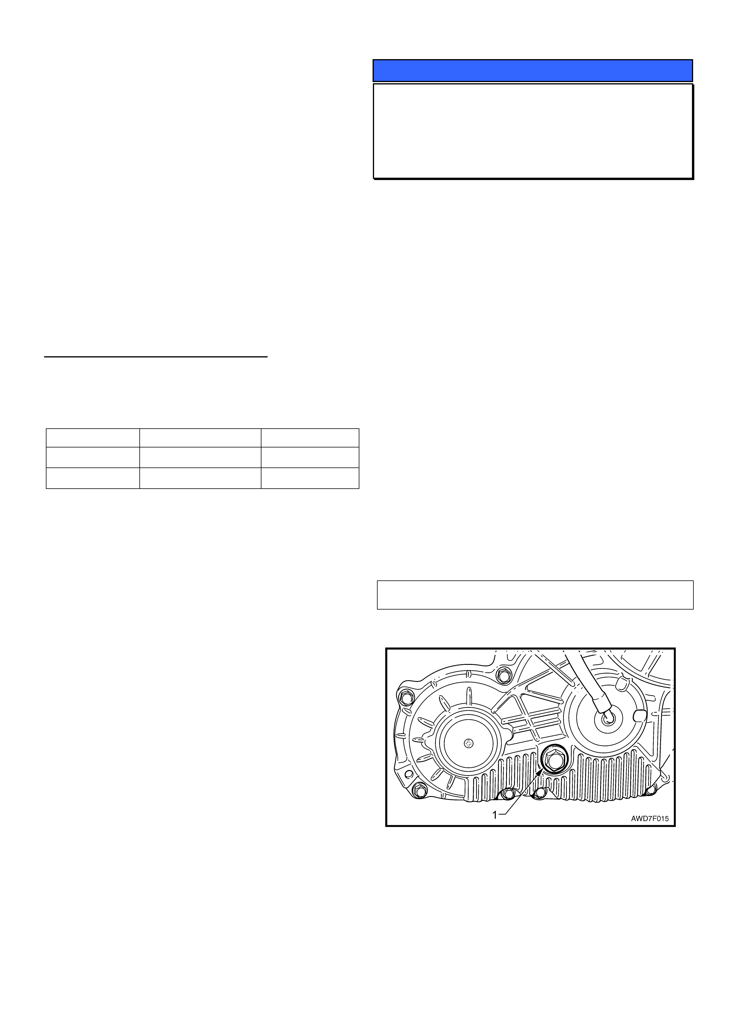
HOLDEN SERVICE TECHLINE _____________________________________________________________OCTOBER, 2004
15
6. Install the return spring (lubrication is not
required)
7. Check that the linkage has correct movement
and does not catch on any other components.
8. Install the lock assembly to the door (Torque
screws to 3-5 NM)
9. Ensure the inner door trim water seal is sealed
correctly to prevent any water leaks.
10. Check the operation of the door lock (manual
and remote), interior and exterior door handles.
NOTE: It is not possible to use the above tool on the
rear door locks.
WARRANTY CLAIM INFORMATION
Refer PV SIP if new lock assembly was fitted.
Refer table below if lock was repaired.
Lock location Labour Operation Time Allowed
RHF C000529 0.8 Hr
LHF C000532 0.8 Hr
SERVICE PROCEDURE
Checking Transfer Case Oil Level
VY AWD Models
GROUP 3 TL0796-0409
The following extract from PV SIP is provided to
highlight the method for checking oil level in the
transfer case on AWD models.
2.1 Checking Transfer Case Lubricant
Level
1. Ensure that the vehicle is level.
2. Clean the area around the filler plug (1).
3. Remove the filler plug and gasket using a suitable size
ring spanner.
4. The level is correct when the lubricant just reaches the
filler plug threads in the rear transfer case housing, when
COLD.
5. Replace the filler plug gasket, then reinstall the filler
plug, tightening to the correct torque specification.
6. Should the lubricant level be found to be low, then the
reason must be investigated and corrected.
7. After correction of the leakage condition, drain and refill
the transfer case. Refer to 2.2 Draining/Filling Transfer
Case Lubricant, in this Section.
Transfer case filler plug torque specification 32 Nm
NOTE
The above view shows the transfer case mount bracket and
rear crossmember removed, to more clearly show the filler
plug location.

HOLDEN SERVICE TECHLINE _____________________________________________________________OCTOBER, 2004
16
Engine Rough Idle – Valve Spring Failure
300 Kw V8 engine
GROUP 6A TL0762-0409
The complete HSV Techline can be viewed on the
Holden Lionheart Portal website.
It can be found under Service Techlines, Year 2004,
Group – HSV.

HOLDEN SERVICE TECHLINE _______________________________________________________________NOVEMBER, 2004
6
SERVICE FIX
A/T Shift Improvements
VY AWD (Adventra & Cross 8)
(GROUP 7B) TL0790-0410
CONDITION
Some customers may report the following:
“aggressive” or “harsh” downshifts or,
“driveline clunk” on light throttle upshifts
CORRECTION – Service
A service fix calibration has been released on TIS CD
54 that improves the above shift conditions. Therefore,
customer complaint vehicles should be reflashed with
current calibration provided on TIS CD 54 (or later).
WARRANTY CLAIM INFORMATION
Use existing Labour Time information in current PV SIP
CD as follows:
Description PCM - Reprogram
Labour Op. No. J987710
Time 0.4 hr
Failure Code NOW K0084 (Hard Shift, Hot)
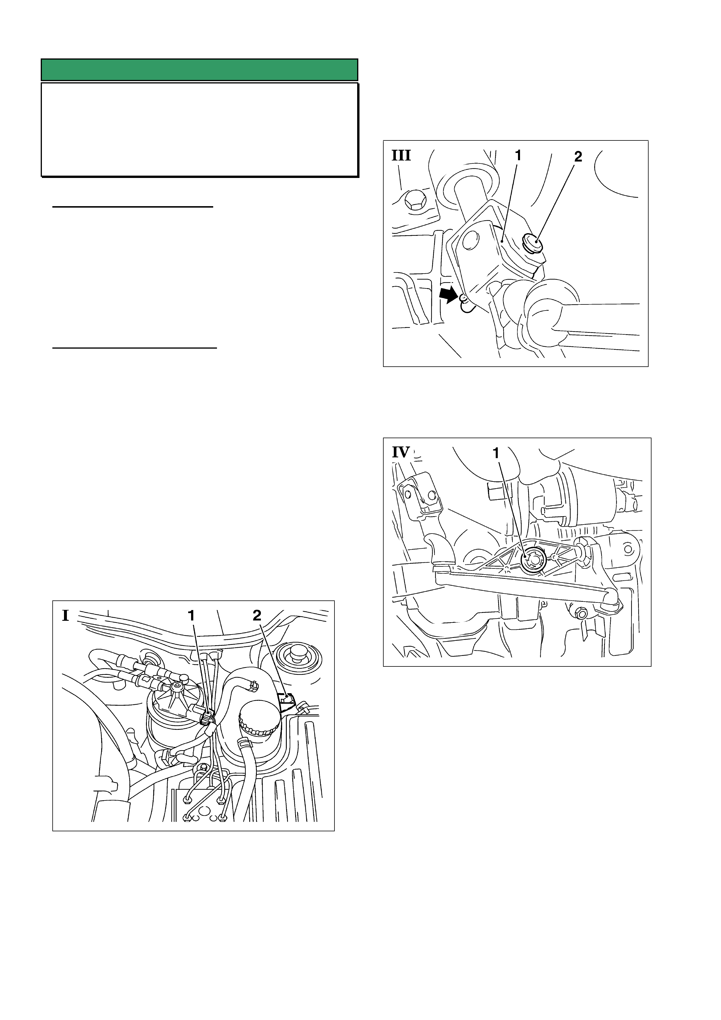
HOLDEN SERVICE TECHLINE _______________________________________________________________NOVEMBER, 2004
7
SERVICE FIX
Gear Shift Linkage Rattle/Failure
XC Barina with M/T
(GROUP 7A) TL0574-0410
PROBLEM DESCRIPTION
A rattle noise may develop in the gear shift linkage on
vehicles which operate for lengthy periods on roads
where substantial amounts of dirt, dust, debris, etc, are
deposited on the shift linkage. Eventually, this may
result in gear shift linkage pivots wearing and
dislodging, with subsequent gear selection problems.
SERVICE RECTIFICATION
On complaint vehicles where the gearshift linkage
pivots have worn excessively, install an improved
linkage assembly as follows:
1. Disconnect battery.
2. Raise vehicle.
3. Remove shift guide from shift rod.
4. Lower vehicle.
5. Remove fastening clip of coolant reservoir
(Picture I, item 2). (Item 1 for other markets Diesel
vehicles only)
6. Unclip coolant hose and lay coolant reservoir aside.
7. To remove universal joint, remove hollow pin with
KM-569-A (Picture III).
Note: For removal of universal joint (1) press in
retaining spring (arrow) of hollow pin (2):
8. Remove safety clip for linkage (Picture IV, item 1).
Note: Safety clip will be destroyed at removal.
9. Detach and remove linkage assembly upwards.
10. Install new linkage assembly, p/n 93176772 and fix
safety clip.
Important: Lubricate all movable parts with silicone
grease, p/n 90167353
11. Install universal joint, secure with new hollow pin.
Important: Retaining spring must engage audibly.
12. Raise vehicle.
13. Install shift rod to shift guide.
Note: Do not fasten the clamp yet.
14. Lower vehicle.
(Step 15 on next page)

HOLDEN SERVICE TECHLINE _______________________________________________________________NOVEMBER, 2004
8
15. Adjust transmission shift linkage
See TIS working procedure "Transmission Shift
Linkage, Adjust (F13/F17)", Group "K", Service
Instruction Corsa-C (Holden Barina).
16. Install coolant reservoir.
17. Install coolant hose.
18. Connect battery.
19. Program volatile memories (radio, etc).
20. Road test vehicle to confirm correct gear selection.
PARTS INFORMATION
Part No.: Description: Qty:
9317677
2
Linkage Asm. 1
9016735
3
Silicone Grease, 100gm 1
9052318
9
Pin – Guide Control to
Trans.
1
NOTE: Grease shown above is a bulk quantity, NOT
for each repair.
WARRANTY CLAIM INFORMATION
Use existing Labour Operation and Time as shown in
Passenger SIP.
INFORMATION
Seat Belt Warning Inoperative Above 25
Km/h
VZ & WL
GROUP 12 TL0817- 0410
Holden is currently investigating reported instances of
where the seat belt warning chime does not operate
following re-configuration of the instrument cluster.
Until the cause of this condition and a solution is
available technicians should avoid re-configuration
where possible.
When a solution is available a further Techline will be
published.
In the event that a customer reports the seat belt chime
is not functioning a nominated contact should contact
Holden Technical Assistance (TAS) for advice.
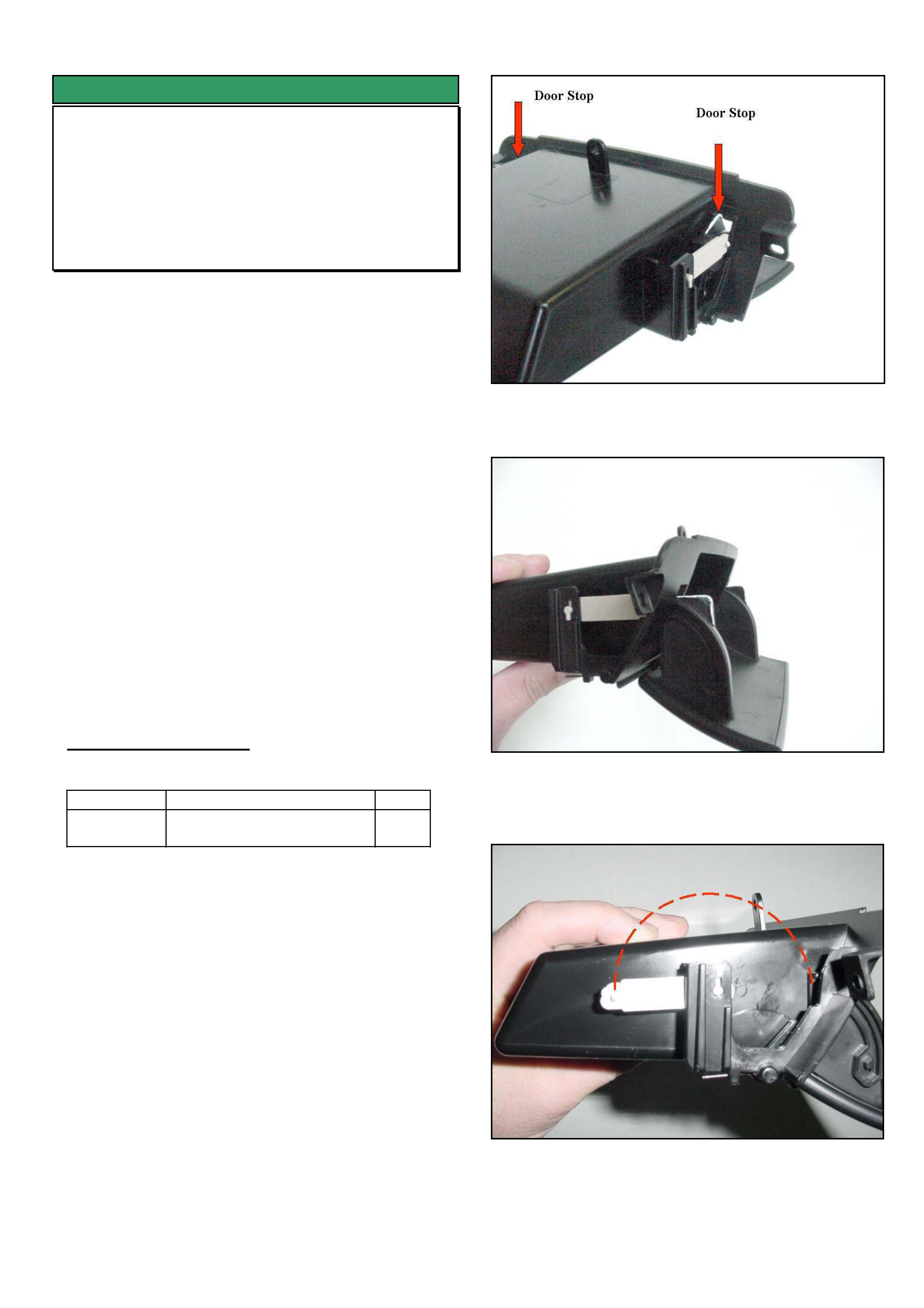
HOLDEN SERVICE TECHLINE _______________________________________________________________NOVEMBER, 2004
9
SERVICE FIX
Front and Rear Console Storage
Compartment – Door Latch Lever
Replacement
VY, VZ, WK, WL
GROUP 1 TL0755-0410
This techline should be read in conjunction with
techline TL472-0305 of May, 2003 which described the
requirement to replace complete storage compartment
assemblies for breakage of the door latch lever.
----------------------------------------------------------------
The purpose of this techline is to advise that the
storage compartment door latch levers are now
available as individual replacement parts. The
replacement procedure is shown as follows.
Replacement Procedure – Door Latch Lever.
1. Push down firmly on the door stops shown in
Figure 1 to allow the door to fully open as shown in
Figure 2.
2. Rotate the latch lever 180 deg. (refer Figure 3) to
allow the lever to be withdrawn.
3. Install new lever and reconnect to door.
4. Return door to original position. (Figure 1)
PARTS INFORMATION
Part No.: Description: Qty:
92148457 Lever - instrument panel
compartment door latch
1
Figure 1.
Figure 2
Figure 3.
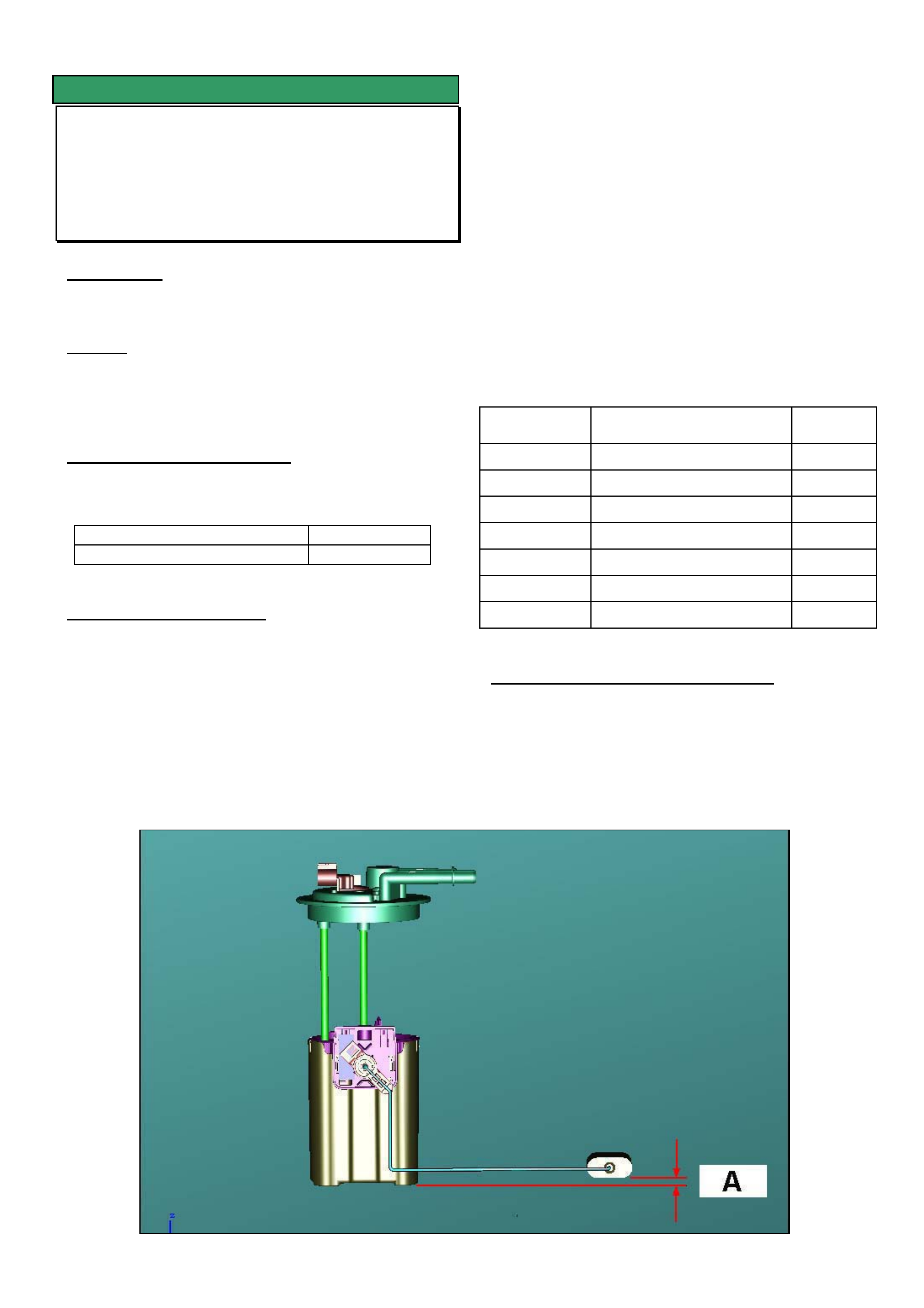
HOLDEN SERVICE TECHLINE _______________________________________________________________NOVEMBER, 2004
10
SERVICE FIX
Fuel Gauge Indicates Higher Level Than
Actual - (Bent Float Arm)
VZ, WL
GROUP 8 TL0809-0410
CONDITION
Fuel gauge indicates higher level of fuel than is actually
in tank.
CAUSE
One possible cause is that the Modular Reservoir
Assembly (MRA) float arm may have been bent during
installation into the tank.
CORRECTION – Production
Checks to ensure that float arm is not bent have been
implemented in vehicles from:
ISOVIN: Built Date:
**********L345644 6/10/04
CORRECTION – Service
1. Remove all useable fuel by pumping using vehicle
fuel pump. Do not remove MRA at this stage.
2. Measure the fuel sender resistance at the body
harness connector for the MRA using a multimeter.
Resistance should be 248.5 +/- 3.3 ohm.
3. If measured resistance is outside of specification
remove MRA and check for a bent float arm. If
resistance is within specification call TAS for
assistance.
4. If arm is bent, carefully rebend to achieve
dimension A shown in picture below.
NOTE: Prior to measuring “A”, ensure that the
bottom of the float is parallel to the surface that the
MRA is sitting on. Dimension A can be determined
from the table below.
5. Recheck the sender operating resistance with float
positioned as shown in picture. i.e. at Empty
position.
Resistance should be 248.5 +/- 3.3 ohm. (245.2 -
251.8 ohm)
6. If resistance is within specification reinstall MRA
into fuel tank.
7. Before filling with fuel, recheck resistance as
before, to ensure arm has not been bent .
MRA Part No. Model Dimension
A
92159903 WL Gen 3 V8 2.0 +/- 2
92163120 WL, VZ Sed & Wag – V6 2.0 +/- 2
92163122 VZ Ute - V6 5.5 +/- 2
92174478 VZ all Gen 3 V8 5.5 +/- 2
92176989 HSV - VZ Ute Gen 4 V8 5.5 +/- 2
92176988 HSV - VZ Sed. Gen 4 V8 2.0 +/- 2
92148352 VZ Cab Chassis tba
WARRANTY CLAIM INFORMATION
Use Labour Times information in Warranty Information
section of current PV SIP CD
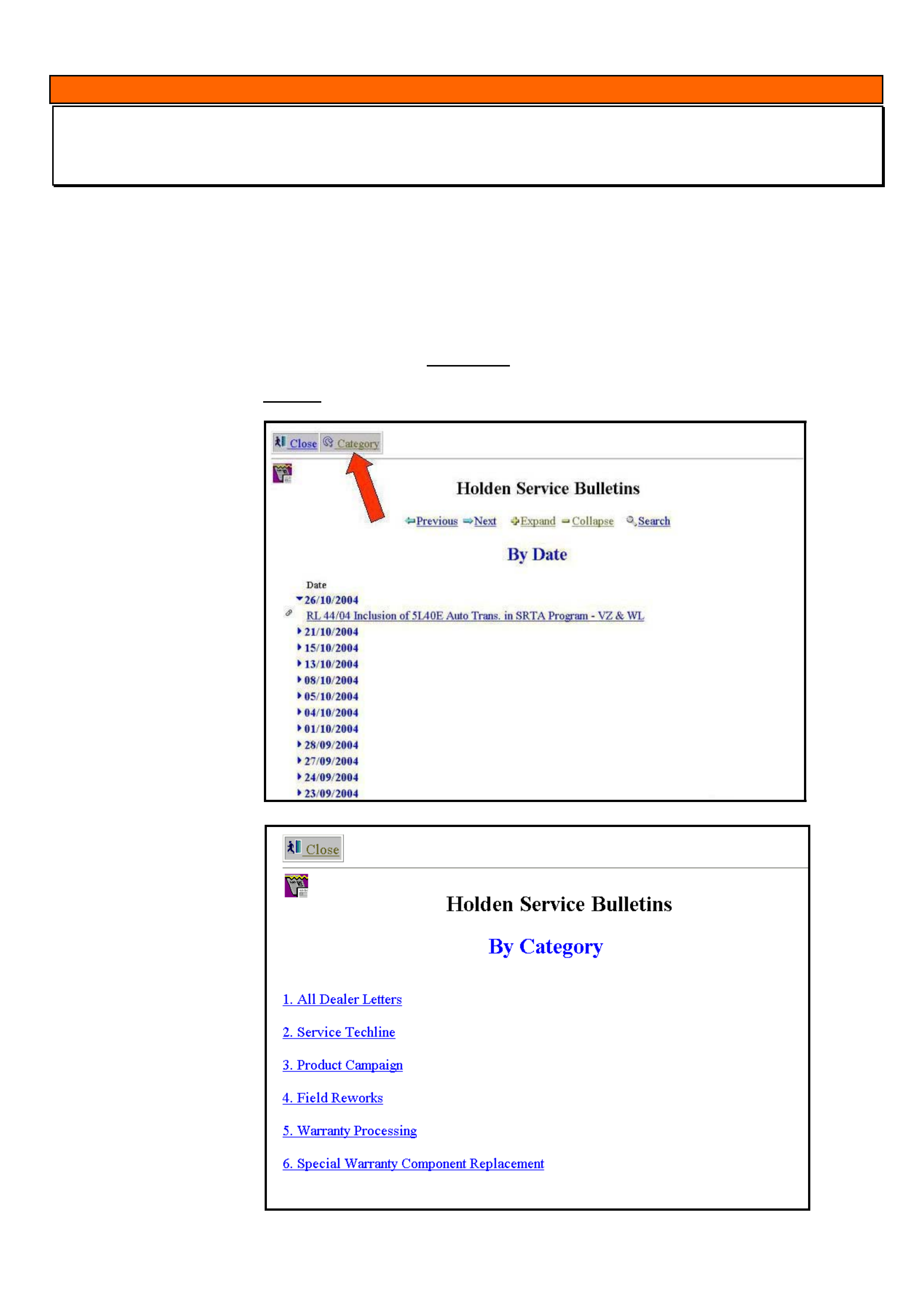
HOLDEN SERVICE TECHLINE _______________________________________________________________NOVEMBER, 2004
11
INFORMATION
Holden Lionheart Portal – Improvements For Viewing Latest Service Bulletins
GROUP OB TL0821-0410
To assist dealers to check the most recent Service Bulletins “posted” onto the Portal we have made the following
revisions.
When you logon to the Lionheart Portal and select “HOLDEN SERVICE BULLETINS”, the first page now appears as
shown in FIGURE 1. The date at the top of the list is the most recent date that a Service Bulletin was loaded onto
the Portal. In this example Retailer Lettter RL 44/04 was loaded onto the Portal on the 26/10/2004. To view the
bulletin simply click on it.
If you wish to view bulletins by category, select the “Category” button at the top of the page shown with red arrow.
This will take you to FIGURE 2, where you can then select whichever category you wish to view. To return to first
page (FIGURE 1) select the “Close” button.
FIGURE 1
FIGURE 2
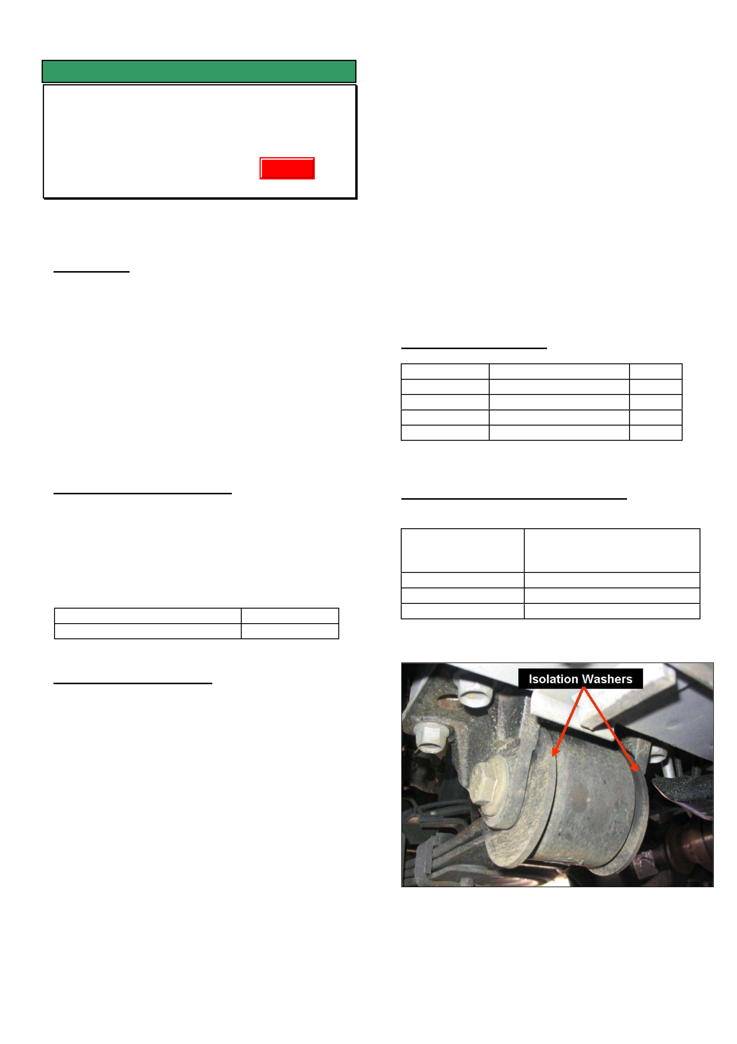
HOLDEN SERVICE TECHLINE _______________________________________________________________NOVEMBER, 2004
12
SERVICE FIX
Diff. Period Whine 80 – 110 km/hr
VY, VZ, V8 One-Tonner & Crewman
(excluding Cross 8)
GROUP 4 TL0631A-0410
This Techline supercedes the previous one in Issue
9, Oct, 2004. It is revised by adding V8 One-Tonner
and correcting the washer part number.
CONDITION
Some vehicles may experience an unacceptable
period whine noise from the differential at
approximately 80 - 110 km/h at light to medium
throttle cruising.
A certain level of rear axle assembly noise is normal
and to be expected on these light commercial type
vehicles due to their cab chassis structure and
associated load carrying requirements.
NOTE: This noise must not be confused with noises
resulting from possible faulty differential bearings or
gears.
CORRECTION – Production
Two countermeasures introduced into production are:
• A softer rubber bush in the front eye of the leaf
spring. - Crewman V8 Auto & M/T
• A 2-spoke pinion flange - Crewman V8 Auto
Breakpoint for both countermeasures is:
ISOVIN: Built Date:
**********L218227 9/3/2004
CORRECTION – Service
Summary: On complaint vehicles, fit a 2-spoke diff
pinion flange and softer bushes in front eye of rear
springs.
Procedure. (For specific procedures not covered in detail
refer to latest PV SIP.)
1. Remove rear springs.
2. Press out existing front eye bush from each
spring.
3. Press in new eye bush 92148815.
4. Reinstall spring assemblies.
NOTE: There are four large washers p/n
92175916 that need to be fitted – one on each
side of the front spring eye bush as
spacers/locators. These washers are only fitted
to vehicles with the revised spring eye bushes.
5. The revised pinion flange 92176653 should be
fitted with the new nut 92146565 exactly as per
procedure found in PV SIP:
Section 4B – Final Drive & Drive Shafts,
2. Minor Service Operations,
2.11 Pinion Flange / Replace using old seal.
CAUTION: Overtightening of the pinion nut may
result in excessive bearing preload and bearing
damage.
6. The alternative to Dealers doing step 5 is to have
a sublet repairer (diff specialist) fit the flange.
Any such repairer must use a torque reading
tension wrench to ensure the pre-load before and
after is the same, otherwise, preload related
noise/failure may occur at a later date.
PARTS INFORMATION
Part No.: Description: Qty:
92148815 Bush Rr Spring Front 2
92175916 Washer 4
92176653 pinion flange 1
92146565 Flange nut 1
WARRANTY CLAIM INFORMATION
Description Replace bush, leaf spring
front eye – both sides and
replace diff pinion flange
Labour Op. No. F000197
Time 2.1 hr
Failure Code F0040 noisy
Update

HOLDEN SERVICE TECHLINE _______________________________________________________________NOVEMBER, 2004
13
DIAGNOSIS HINT
Differential Clunk Noise
VY & VZ One-Tonner & Crewman
GROUP 4 TL0815-0410
CONDITION
A clunk noise heard coming from the rear end of the
vehicle during “tip-in” or “tip-out” or whilst operating
the clutch on M/T vehicles.
Tip-in = applying the throttle (lightly)
Tip-out = de-applying the throttle.
CAUSE
A possible cause for the clunk is excessive backlash
in the rear axle.
CORRECTION - Service
Step 1. Perform a thorough under-vehicle
visual inspection of the entire driveline, including
transmission, propshaft CV's and rear axle for any
obvious looseness.
Step 2. Perform a rear axle backlash check
using the procedure described in PV SIP found as
follows:
Section 4B2 – Rear Final Drive and Live Axle
2 – Minor Service Operations
2.6 – Combined Rear Axle Backlash Check
IMPORTANT: Backlash reading should be 3.0 mm
maximum, when measured on the head of one of
the pinion flange bolts. PV SIP currently states
7.0 mm. which is now revised to 3.0mm and will
be corrected in the next issue of SIP.
Should the measured backlash be greater than
3.0mm when requesting a replacement axle
assembly – the measured backlash dimension MUST
be included in the Dana request application (via the
Dana website).
DO NOT request a replacement axle if backlash is
less than 3.0mm, as a replacement axle assembly is
not expected to improve the noise heard.
NOTE: A certain level of rear axle assembly noise is
normal and to be expected on these light commercial
type vehicles due to their cab chassis structure and
associated load carrying requirements.
Update

HOLDEN SERVICE TECHLINE _______________________________________________________________NOVEMBER, 2004
14
SERVICE PROCEDURE
Resetting Automatic Power Window
Operation - Includes Comfort Opening
& Closing On ZC Vectra & AH Astra
All OPEL Vehicles with Power Windows
GROUP 12 TL0812-0410
The following 3 functions apply to ALL Opel vehicles
with power windows:
• Auto up and down if the window switch button is
held for more than 0.5 second,
• Pinch Guard. During the auto up operation the
window will stop, then retract downward
approximately 100mm if anything prevents it from
reaching the top of its travel.
• Automatic closing of any power window from the
drivers door lock, when the key is held in the lock
position for more than 1 second.
Comfort Opening & Closing – ZC & AH.
• A new feature fitted only to ZC Vectra and the
new AH Astra is opening or closing all the
windows via the remote key. Holding down the
unlock button will lower the windows. Holding
down the lock button will raise the windows.
All the above automatic functions will be lost if
the vehicles battery is disconnected, or the
appropriate fuse or power supply to the power
window system is disconnected. Each electric
window motor has its own module attached to it.
This also applies whenever a door wiring harness is
disconnected.
RESETTING PROCEDURE
To reset all the above automatic functions, do the
following:
1. Reconnect power supply to the power window
system or an individual door that may have been
disconnected
2. Turn on the ignition.
3. Ensure all windows are at the top.
4. For each window, hold down the “up button” at
the drivers door main switch for 5 seconds –
usually a “click” will be heard coming from each
door.
5. After this, ensure that each window’s automatic
up and down function operates.
DIAGNOSIS HINT
Reverse Gear Selection “Hard”
VZ V6 with M/T
GROUP 7A TL0822-0410
Condition
Some customers may be concerned by a high effort
being required when shifting into Reverse gear.
Cause
This transmission has First and Reverse gears
located side by side. The Reverse gear detent has
been designed with a distinct “step” in the
mechanism to ensure that either gear cannot be
selected accidentally.
If Reverse gear is selected slowly – a very high effort
will naturally be required to overcome the “step”.
Solution
If Reverse gear is selected “with momentum” - IE: if
the lever is moved rapidly towards the Reverse gate -
the mechanism “step” is easily overcome and the
reverse selection will be achieved with much less
effort.
This method of selecting Reverse gear should be
explained to any customers who raise “hard” Reverse
selection as a concern.
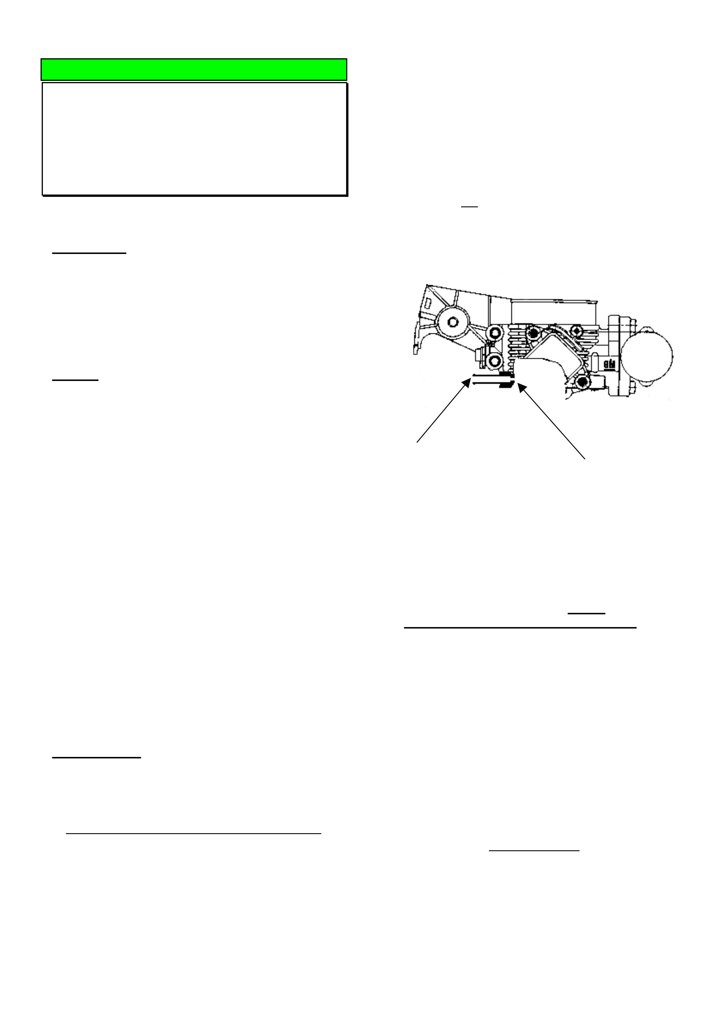
HOLDEN SERVICE TECHLINE _______________________________________________________________NOVEMBER, 2004
15
DIAGNOSIS HINT
DTC P0100 / Poor Idle / Engine Stall
(Non - IACV Related Causes)
JR, JS, C20SEL, C22SEL
(GROUP 6C) TL0708-0410
This information is repeated from June 2002
Techline.
CONDITION
PIR’s have been received advising that vehicles have
not responded to fitting of new IAC valves as
described in June 2002 Techline titled “Engine stall at
idle” or “High engine idle speed”. These reports
mention that vehicles have a DTC P0100 (MAF
Sensor Voltage Low) set and the engine idle is
unstable or may stall at odd times.
CAUSE
Investigations have shown that possible causes for
above symptoms are as follows.
A. Blocked PCV hose/port in throttle body.
The hose/port may become blocked by
contaminants carried in PCV gas and over
time, the build-up will block the small calibrated
hole in the throttle body.
B. Loose elbow in air intake duct (above throttle
body);
C. Damaged TPS housing on the throttle body;
D. Damage/deterioration to secondary PCV hose;
E. Purge valve hoses fitted in reverse.
F. MAF sensor faulty
G. Fuel Pump or Injection valve relay fitment.
H. Crankshaft or Camshaft sensor.
NOTE: As a general rule, any stall that occurs above
4km/h is not IACV related, and requires diagnosis to
ensure a cause is found and corrected.
CORRECTION
On any vehicle with the condition as described
above, check the identified potential problem areas
(A - H) and rectify as required.
A. BLOCKED PCV HOSE/PORT IN THROTTLE BODY
Blockage of the PCV hose/port causes the engine to
run on IACV air only. Engine system calibration is
based on specific air flow through the PCV port PLUS
IACV air at high vacuum times (idle/decel) and thus,
loss of air flow through the hose/port can result in
poor idle and possibly stall.
NOTE: The following procedure applies to JR/JS
C22SEL engined vehicles built prior to introduction of a
revised PCV system that feeds PCV gas into the lower
part of the inlet manifold – these were built from:
WOLOJBF19YL557427, Build Date 16/02/00, Engine
No.: C22SEL25015395.
Diagnosis:
While engine is idling, remove the PCV hose from the
cam cover and check if there is vacuum at the free
end of the hose.
If vacuum is not present, remove the PCV hose from
the throttle body port connection and check if there is
vacuum at the port. This port is shown in the cross
section diagram below, looking from rear of throttle
body
Contamination builds up
in PCV connector, Calibrated hole
(A) – If vacuum is present at the port replace the
PCV hose. No further action is required.
(B) - If there is no vacuum at port then proceed to
clean the port as follows.
This hole can be carefully cleaned out as follows:
1. Obtain a 1.5mm Diameter, long drill bit from an
engineering supplies outlet. NOTE: this drill bit
MUST not be larger than 1.5 mm Dia., as the
hole is calibrated. Enlarging the hole will result in
incorrect air flow, and causing driveability or further
code setting problems.
2. Remove the main air intake hose from the throttle
body;
3. Using the 1.5mm Dia. drill bit, carefully insert the
drill into the connection and rotate the drill BY
HAND until the deposits in the connection are
dislodged and the drill freely passes through the
calibrated hole into the throttle body inlet passage.
4. Check this by: removing the drill bit from the
throttle body port completely, then open the throttle
blade fully and hold it fully open, insert the drill bit
until it protrudes from the calibrated hole – then
remove drill bit and then close throttle blade.
5. Clean the connection with a solvent or spray
cleaner and remove any debris left in the
connection hole and throttle body;
6. Re-check that the hole is clear using the drill bit,
and re-assemble previously removed components.
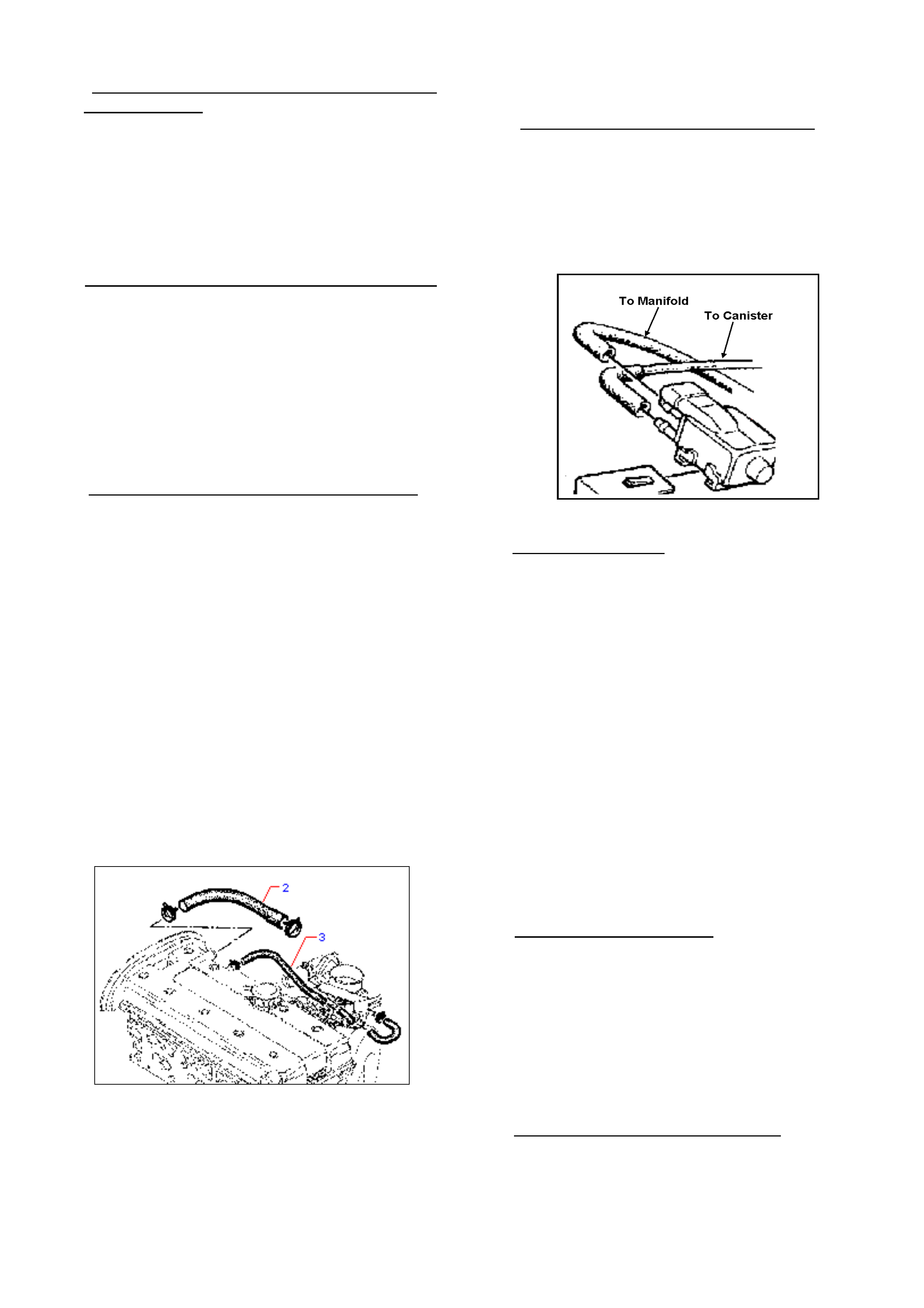
HOLDEN SERVICE TECHLINE _______________________________________________________________NOVEMBER, 2004
16
B. LOOSE ELBOW IN AIR INTAKE DUCT ABOVE
THROTTLE BODY
Should this elbow be “loose” in the main air intake
duct, the additional un-metered air entering the
system can cause driveability problems, poor idle,
and a P0100 to set.
If the elbow is loose – replace the inlet duct
(containing the elbow).
C. DAMAGED TPS HOUSING ON THE THROTTLE BODY
While this should be a rare occurrence - if the TPS
housing has been damaged in some way that allows
air/water/dust, etc to enter the body, the resulting
contamination can cause incorrect
operation/readings. EG: Damage during any service
operations, engine/trans. removal, etc. Any TPS
found with damage to the external body must be
replaced with a new TPS.
D. DAMAGED/ DEGRADED SECONDARY PCV HOSE
Stalling may be caused if the secondary PCV hose
(Item 2 shown in the diagram below) is split or torn, or
the inner hose walls deteriorate:
Damage (split or torn):
Allows air to by-pass the mass airflow sensor, leading
to incorrect airflow readings which affect the engine
fuel ratio (runs lean). A DTC P0100 may be set.
Degraded:
Degradation of the hose can result from age and
exposure to PCV gases, and external contaminants
which affect the hose. The hose should be carefully
examined for physical degradation, EG: softness,
cracking, hardness, etc, and replaced if necessary.
Extreme build-up of PCV contaminants to the point
where the hose is blocked or cleaning is
uneconomical also dictates that the hose should be
replaced.
Deterioration of hose inner walls:
Allows particles of the deteriorated hose material to
separate from the hose, and these may become
lodged in the ‘early design’ or “old” IACV leading to a
stall. This will not occur with the ‘later design’ or
“new” IACV – however, the hose should be examined
and replaced where necessary.
NOTE: kinking, or clamping any other components to
the secondary PCV hose is NOT permitted.
E. PURGE VALVE HOSES FITTED IN REVERSE
The hoses at the canister purge valve must be fitted
the correct way – with the throttle body hose at the
top purge valve fitting – as shown below:
If these hoses are reversed – damage to the purge
valve may result – if this has occurred it is
recommended that the purge valve be replaced.
F. MAF SENSOR FAULTY
Stalling associated with the MAF Sensor can occur
either while vehicle is moving or stationary. Usually a
DTC P0100 is set. (this DTC may also be set by a
fluctuating idle, so correct diagnosis of type of stall is
required).
Some findings on failed MAF Sensors have been:
♦ Fretting corrosion of the MAF Sensor terminals.
(Replace suspect terminals.)
♦ Connectors not fully or correctly installed. (Check
connections and re-install if required.)
♦ Incorrect routing or attachment of sensor wiring.
(Check wiring against a known OK vehicle to ensure
the wiring is not run in an incorrect routing, so it does
not pick up any ‘stray’ electrical signals from other
wiring or components.)
G. RELAY INCORRECT FITMENT
If the “Fuel pump” or “injection valves” relays are not
properly fitted – with their terminals fully engaged in
the mating connector/wiring, a stall may be caused.
Check relays for full and proper connection, re-install
if required. Some relays are a very tight fit and may
not have been fully seated on fitting or subsequent
replacement.
H. CRANKSHAFT OR CAMSHAFT SENSOR
Refer to Techline bulletins of February and March,
2000 relating to these sensors – available on your
SIP CD. Replace any pre-breakpoint parts.
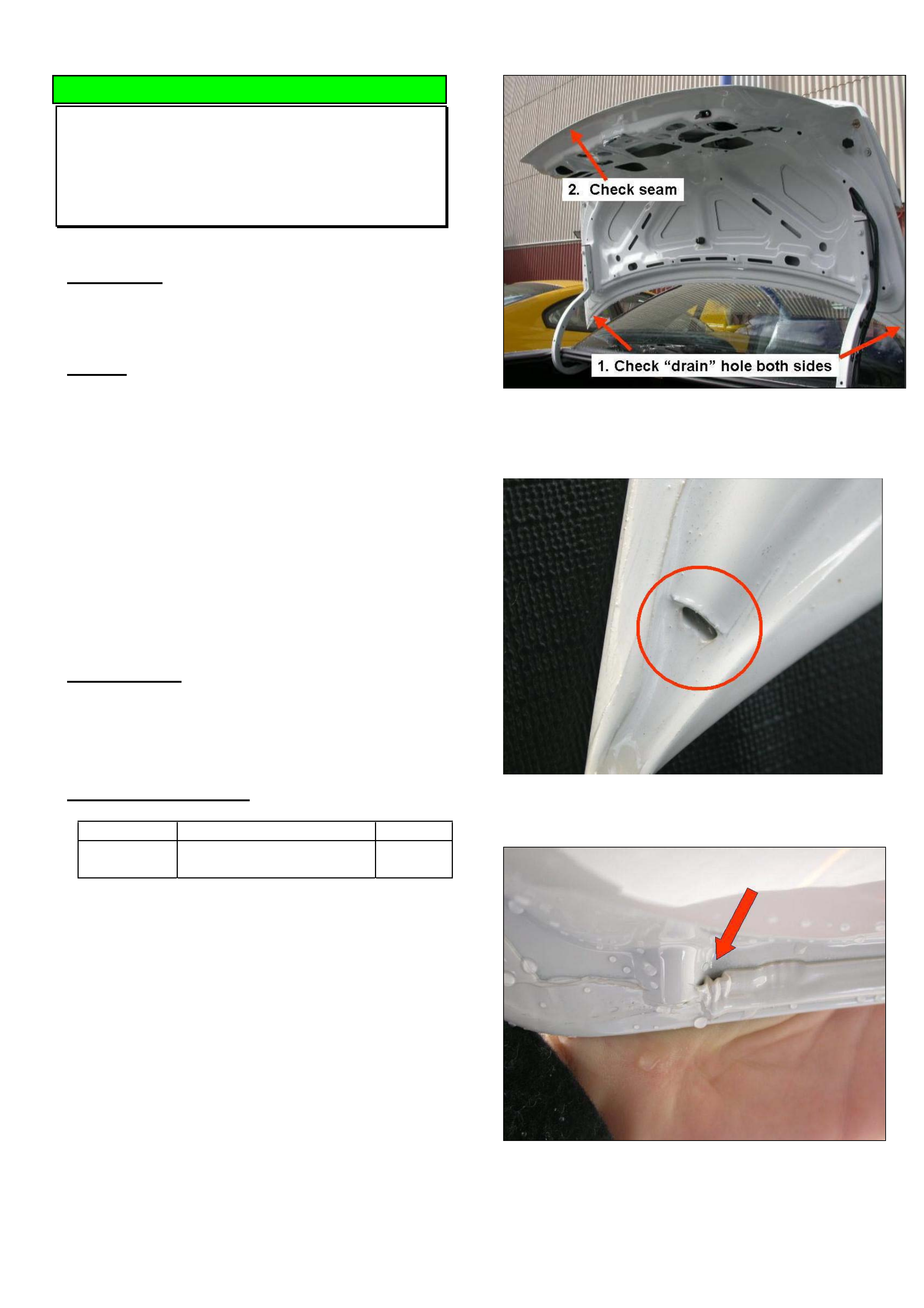
HOLDEN SERVICE TECHLINE _______________________________________________________________NOVEMBER, 2004
17
DIAGNOSIS HINT
Water In Decklid
VY, VZ, V2, WK, WL,
Group 1 TL0767-0410
CONDITION
Water in decklid.
CAUSE
Two possible water entry areas are shown in Figure
1.
1. Production Drain Holes
There are two holes in the leading edge of the
decklid used as drain holes in the corrosion
protection dipping process. These holes are normally
sealed prior to the painting process. Refer Figure 2.
2. Seam
The seam between the outer and inner decklid
panels should be inspected for missing sealer. Check
full circumference of the decklid. Refer Figure 3.
CORRECTION
Seal drain holes or gaps in seam as required with a
sealer such as silicone RTV sealer part number
92140051 (75g tube) .
PARTS INFORMATION
Part No.: Description: Qty:
92140051 Silicone RTV sealer 75g
tube
1
Figure 1. Potential water entry points.
Figure 2. Shows an “un-sealed” drain hole.
Figure 3. Shows gap which can occur in seam
sealer.
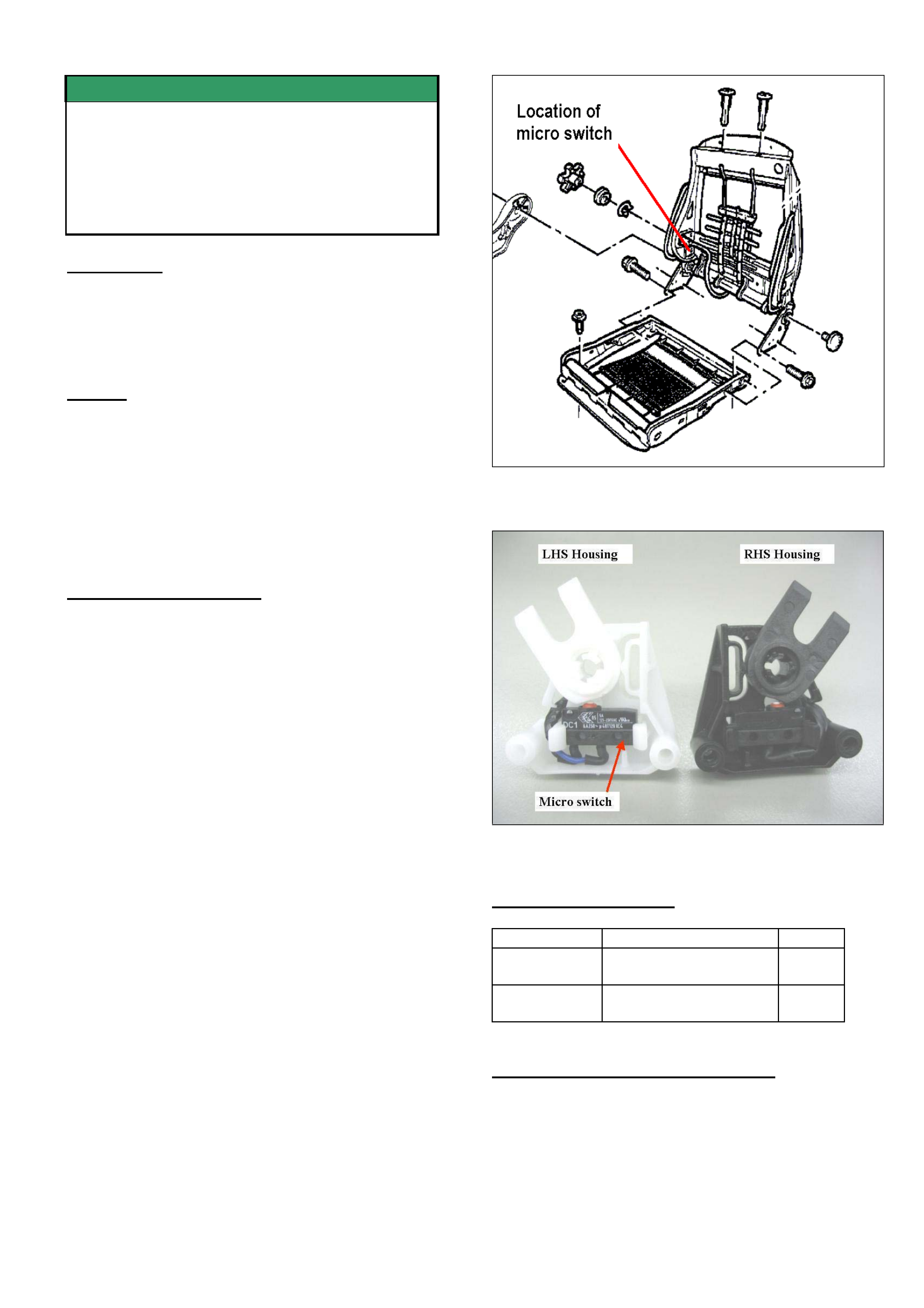
HOLDEN SERVICE TECHLINE _______________________________________________________________NOVEMBER, 2004
18
SERVICE FIX
Front Seat Easy Entry Function
Inoperative In Forward Direction
V2 Series 3
GROUP 1 TL0801- 0410
CONDITION
Front seat does not move forward when the “Easy
Entry” lever is unlatched and the seat back tilted
forward.
CAUSE
A potential cause for this condition is poor retention of
the micro switch in its housing. (Refer to Figure 1 for
location of switch). If the switch is loose in its
housing, the Easy Entry lever cam will fail to activate
the switch. To verify if this is the cause, remove the
front seat back upper cover and check if the micro
switch is firmly retained in its housing.
CORRECTION – Service
Summary: After verifying that vehicle has condition
as described above, fit a new micro switch housing
as per following procedure.
Procedure.
(For specific procedures not covered in detail, refer to PV SIP.)
1. Remove seat-back cover.
2. Remove lumbar knob.
3. De-trim the side of seat to gain access to the 2
micro switch housing attaching screws located
just below the lumbar knob.
4. Remove micro switch housing from seat frame.
5. Detach micro switch from old housing and
discard housing.
6. Take new housing and rotate U shaped cam to
the up position as shown in Figure 2.
7. Insert micro switch into the new housing & press
firmly until the securing hooks snap into place.
8. Feed the switch wire through the hook in the
housing.
9. Re-attach switch housing to the seat frame.
10. Re-trim seat side.
11. Re-assemble seat back.
Figure 1.
Figure 2. Shows microswitch installed into housing.
PARTS INFORMATION
Part No.: Description: Qty:
92148933 Retainer power seat
switch/wiring -RH
1
92148934 Retainer power seat
switch/wiring - LH
1
WARRANTY CLAIM INFORMATION
At the time of printing, warranty claim
information was still being developed. Until this
information is published, contact your Aftersales
District Manager.
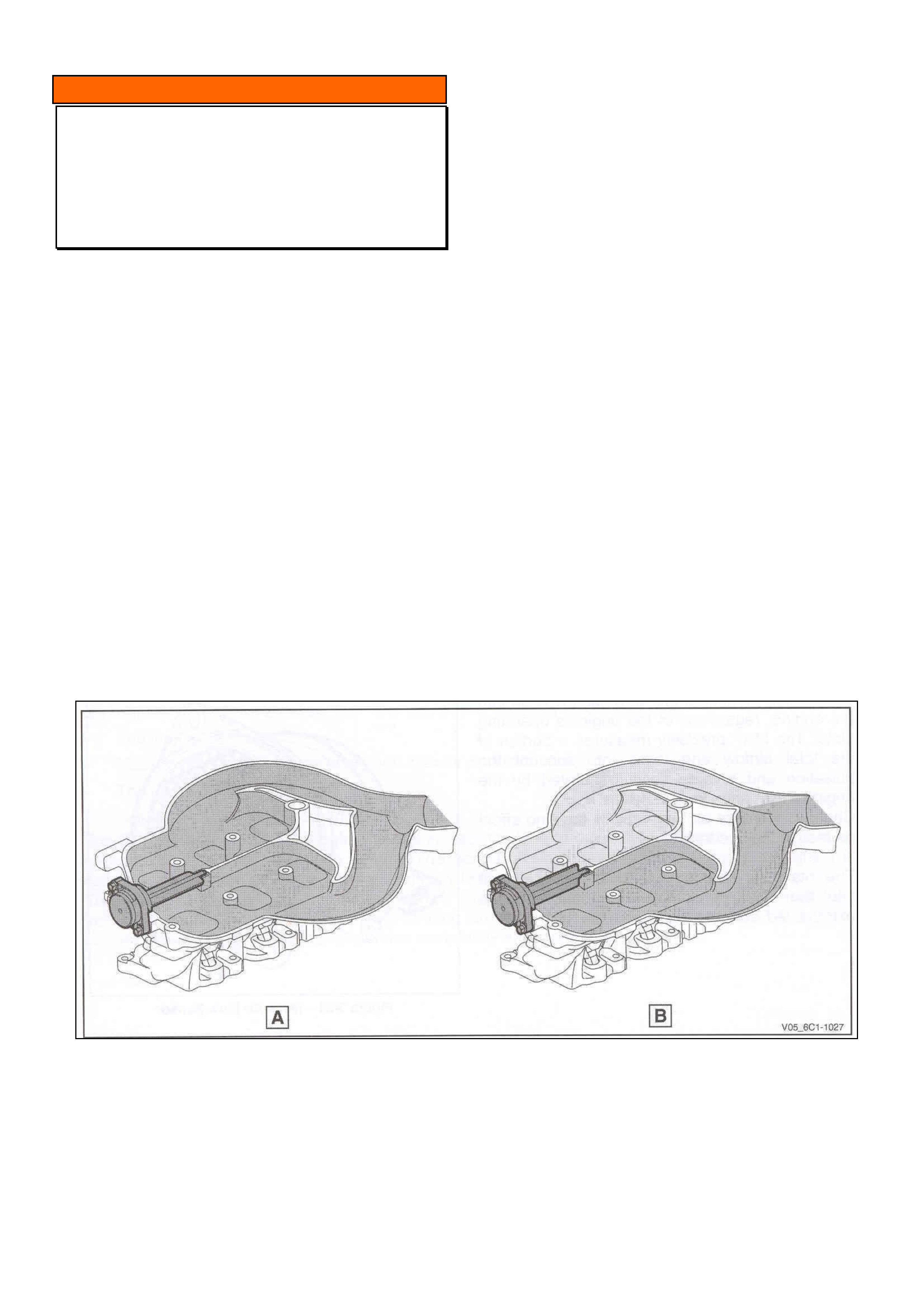
HOLDEN SERVICE TECHLINE _______________________________________________________________NOVEMBER, 2004
19
INFORMATION
Intake Manifold Runner Control Valve
Clunk
Alloytec V6 “190”
GROUP 6C TL0799-0410
A small number of customers may notice a light clunk
sound coming from the Alloytec 190 engine at low
engine speeds and high loads.
In most cases this sound will be due to the operation
of the Intake Manifold Runner Control (IMRC) valve
fitted to the Alloytec 190 engine.
The purpose of the IMRC is to alter the volume of the
intake manifold runners. Varying the intake manifold
takes advantage of natural pulse / pressure waves
occurring in the manifold that are created by the
process of air induction into the cylinders. At a given
engine speed, the manifold can be tuned to increase
the air charge into the cylinders via the returning
pulse waves to achieve higher engine torque.
Note the IMRC valve is two position only as shown
below, open (A) / closed (B), It is not continuously
variable. In the rest position the valve is open.
Use this techline to help customers understand the
reason for the noise they are concerned about.
A = VALVE OPEN
B = VALVE CLOSED
HOLDEN SERVICE TECHLINE _______________________________________________________________NOVEMBER, 2004
20
Service Tools
HSV – Z Series Coupe
GROUP OB HSV Bulletin 099/04
There are 2 new service tools required for mechanical
repairs on this new model.
• Pinion flange holding tool.
• Pinion flange extractor tool.
For complete details refer to HSV Bulletin No. 99/04
on the Holden Lionheart Portal website. It can be
found under Service Techlines, Year 2004, Group
OB – General Information.
Service Readiness
HSV – Z Series
GROUP OB HSV Bulletin 101/04
For complete details on the following:
Tech II Software, SIP, Technician Training, Special
Service Tools, Revised Service Schedules, Exterior
Changes, Interior Changes and New Powertrain
Features,
refer to HSV Bulletin No. 101/04 on the Holden
Lionheart Portal website. It can be found under
Service Techlines, Year 2004, Group OB - General
Information.
Tech II Software
HSV - Z Series
GROUP OB HSV Bulletin - 108/04
Should you require Engine or Transmission
calibrations for HSV VZ or WL before January 2005
contact HSV on (03) 9265 9500. for further
instructions.
Engine and transmission calibrations will be available
on TIS 2000 in January 2005.
Refer to HSV Bulletin No. 108/04 on the Holden
Lionheart Portal website. It can be found under
Service Techlines, Year 2004, Group OB – General
Information.
Matt Paint Finish
HSV – Z Series
GROUP 1 HSV Bulletin 100/04
This new model has matt finish paint accents which
require specific care.
For complete details refer to HSV Bulletin No. 100/04
on the Holden Lionheart Portal website. It can be
found under Service Techlines, Year 2004, Group 1 -
Body.
Use Of Mobil 1 in HSV LS1 Engines
HSV
GROUP 6A HSV Bulletin - 115/04
This bulletin provides information on use of Mobil 1 in
LS1 engines and clarifies the oil consumption
specification for these engines.
Refer to HSV Bulletin No. 115/04 on the Holden
Lionheart Portal website. It can be found under
Service Techlines, Year 2004, Group 6A – Engine.
Tyre Rotation Caution
HSV AWD Coupe 4
GROUP 10 HSV Bulletin - 102/04
On the HSV Coupe 4 model the front to rear tyre
rotation cannot be performed due to the rear wheels
being wider than the front wheels.
For complete details refer to HSV Bulletin No. 102/04
on the Holden Lionheart Portal website. It can be
found under Service Techlines, Year 2004, Group 10
– Wheels & Tyres.
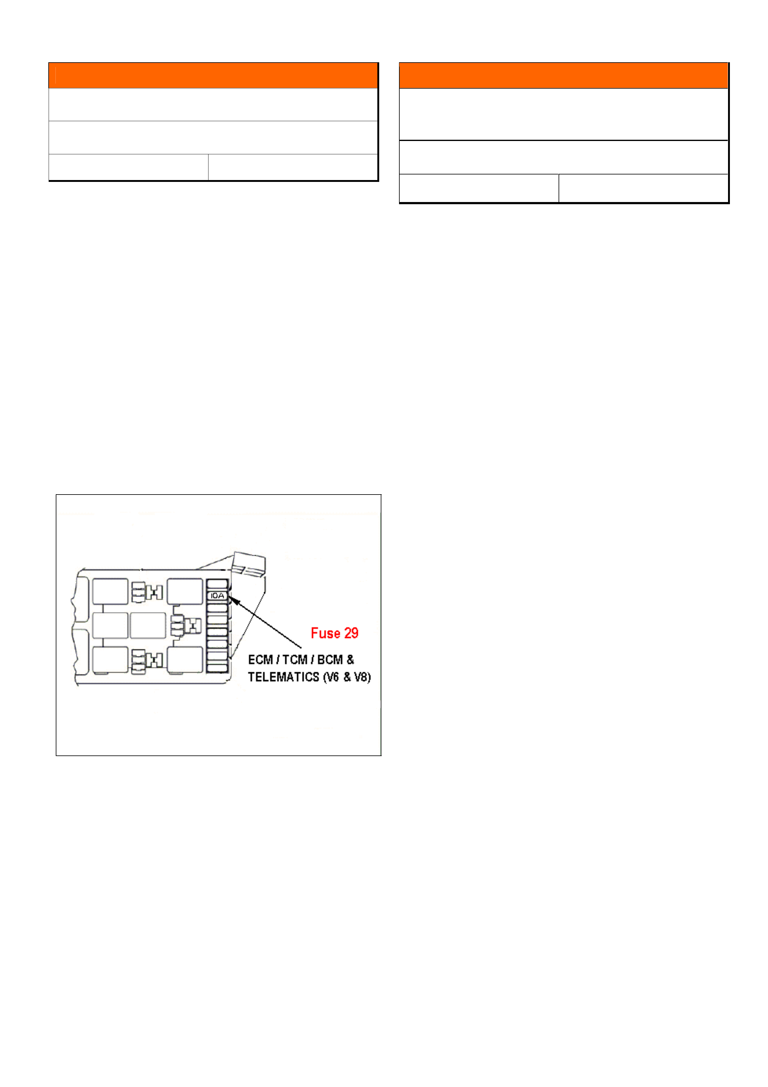
HOLDEN SERVICE TECHLINE _______________________________________________________________DECEMBER, 2004
7
INFORMATION
Incorrect Fuse Fitted
VZ, WL
Group 12 Ref. No. TL0823- 0411
Some dealers may observe that fuse No. 29 - ECM /
TCM / BCM & Telematics (V6,V8) in the engine
compartment fuse/relay box is a different rating to that
shown on the cover.
Typically, a 7.5A fuse is fitted in a V6 and a 15A fuse in
a V8 although a 10A fuse is shown on the cover.
Despite this discrepancy, Engineering Dept. advise
there are no adverse consequences.
However, we suggest if you are replacing fuse 29 for
any reason, it be replaced with a fuse of the same
rating as that shown on the fuse box cover.
The above situation will be rectified in vehicle
production at the earliest opportunity.
INFORMATION
Tripmeter Resets When Battery
Disconnected
VZ , WL
Group 12 Ref. No. TL0827- 0411
After the battery is disconnected and reconnected on
the above models, the tripmeter will reset to the value
shown on the odometer. If the odometer reading is
greater than the maximum allowable trip distance of
99,999 the trip meter will reset to this value (99,999).
This is normal operation.
On previous models the trip distance will reset to zero
when the battery is disconnected / reconnected.
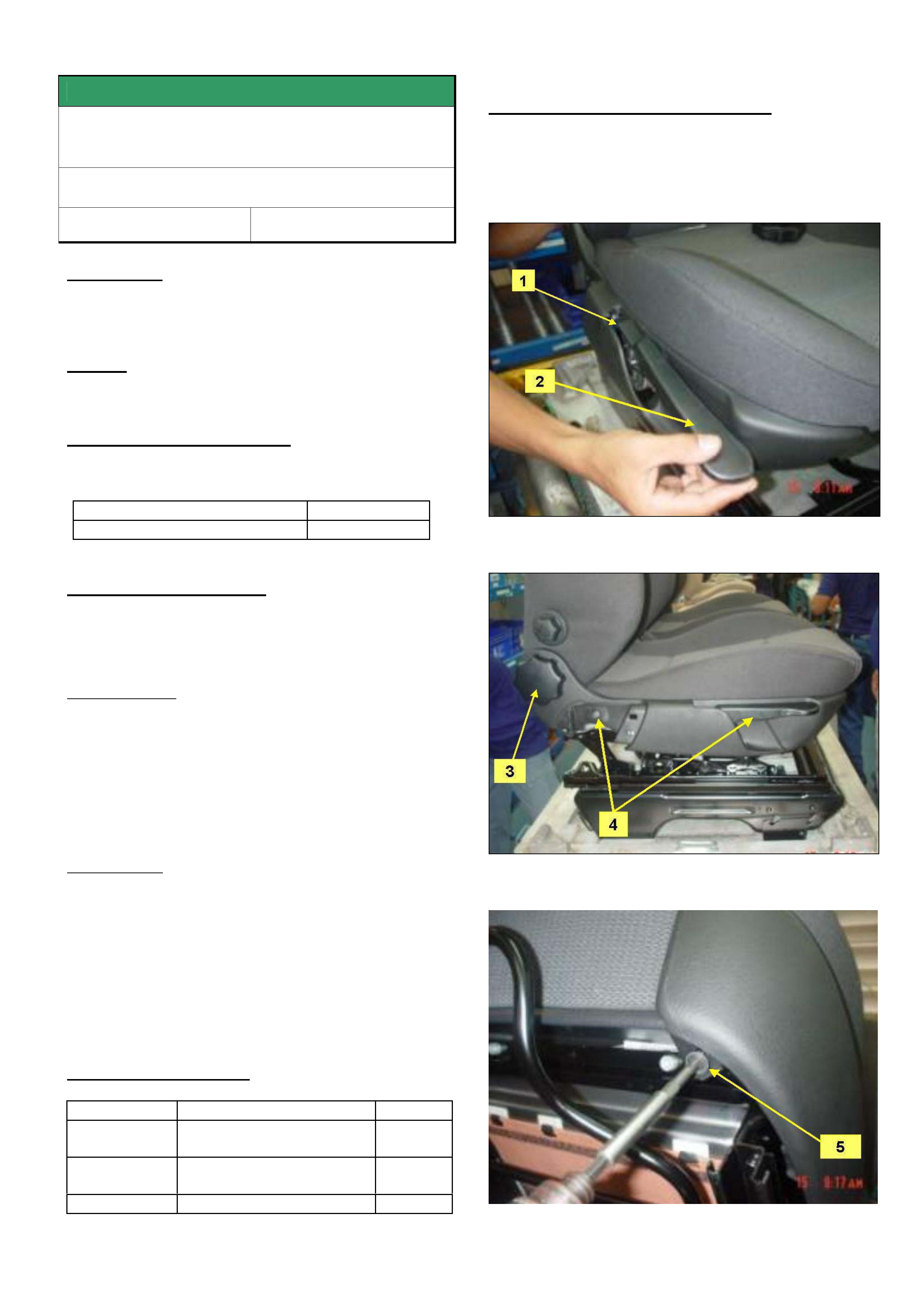
HOLDEN SERVICE TECHLINE _______________________________________________________________DECEMBER, 2004
8
SERVICE FIX
Front Seat Plastic Side Covers Fracture
At Attaching Point
TT Zafira
Group 1 Ref. No. TL0801- 0410
CONDITION
Front seat side outer cover comes loose at front
attaching point.
CAUSE
Side cover mounting tab breaks.
CORRECTION – Production
A washer has been added under the head of the side
cover front attaching screw on vehicles from:
ISOVIN: Built Date:
All vehicles built from 01/07/04
CORRECTION – Service
Summary: On vehicles with above condition, replace
broken side cover and add specified washer under the
front attaching screw.
Remove Cover
1) Remove seat belt cover.
2) Remove screw to plastic cover height adjuster and
plastic clip handle (RHS only)
3) Remove plastic adjuster wheel.
4) Remove height adjuster handle retaining clip (RHS
only)
5) Remove attaching screw - seat cover side outer.
Re-assemble
1) Replace damaged seat side cover with a new one.
2) Refit plastic clip handle height adjuster (rh side
only)
3) Refit plastic adjuster wheel.
4) Fix screw to plastic cover height adjuster and
plastic clip handle (rh side only).
5) Add a washer p/n 92171381 under attaching screw
as shown in Figure 3.
PARTS INFORMATION
Part No.: Partfinder Name: Qty:
90455894 Cover - Seat Rail Outer
– Drivers side
1
90455889 Cover - Seat Rail Outer
– Passenger side
1
92171381 Washer 1/ side
WARRANTY CLAIM INFORMATION
Use Labour Times information in Warranty Information
section of current PV SIP CD.
Figure 1
Figure 2
Figure 3
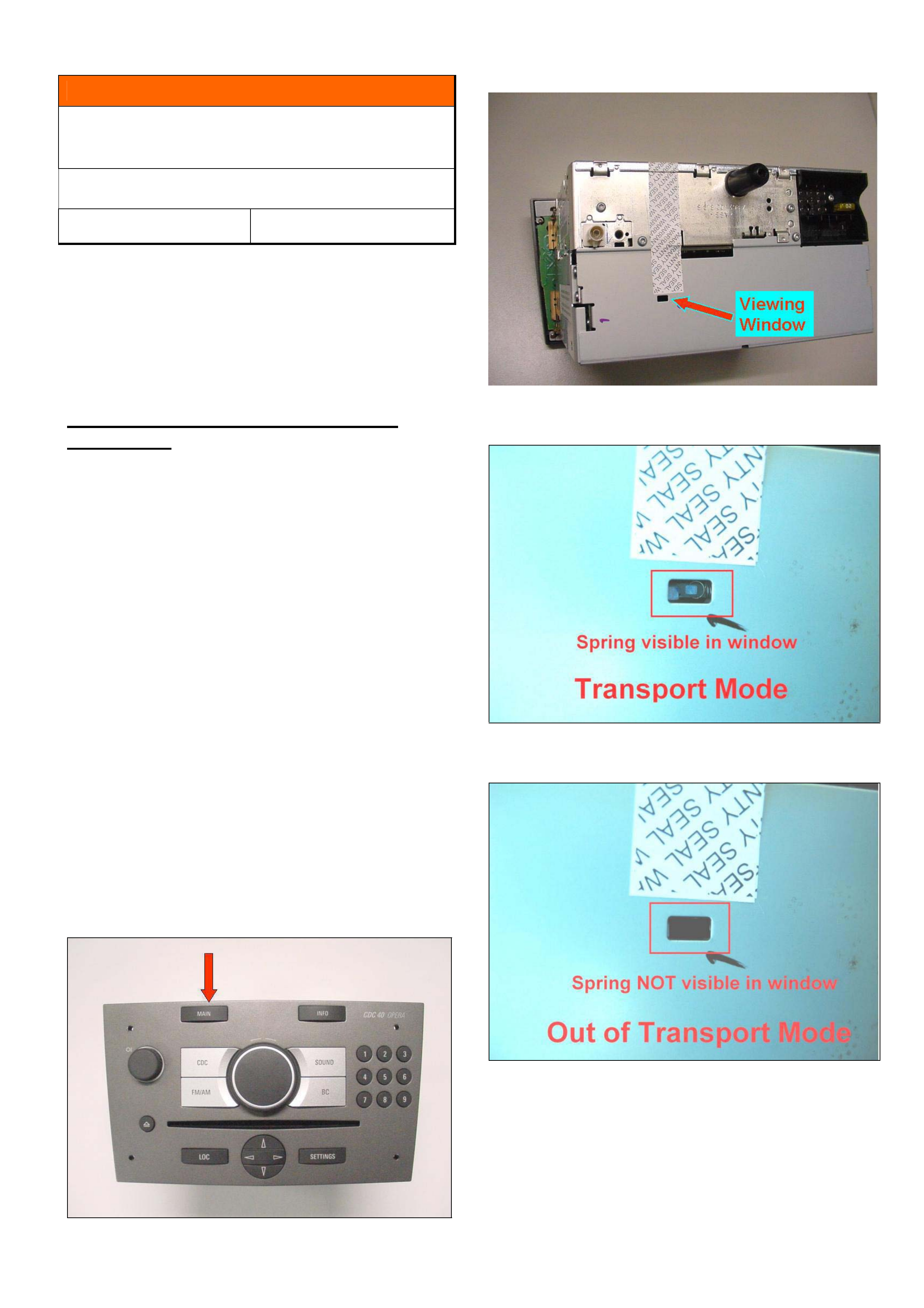
HOLDEN SERVICE TECHLINE _______________________________________________________________DECEMBER, 2004
9
INFORMATION
Activating “Transport Mode” on 6 Stacker
CD Unit
AH Astra, ZC Vectra (Model Year 05)
Group 12 Ref. No. TL0828- 0411
Whenever a “CDC 40 OPERA” audio head unit is to be
returned to Bosch for warranty purposes, the unit must
be set into TRANSPORT MODE as per the following
procedure.
This action is necessary to avoid internal damage to
the CD mechanism during shipping.
TRANSPORT MODE - CDC 40 OPERA
Audio Units
Activation:
1. Switch off Radio
2. Press “MAIN” button (see Figure 1) on Radio and
hold while switching on via ON/Off Button.
3. Keep “MAIN” button pressed for approx. 5 seconds,
until beep is heard.
When transport mode is active, a spring is visible in a
small window at the back of the unit . Refer Figure 2 &
3. When transport mode is inactive, there is no spring
visible in the window. Refer Figure 4.
Notes:
• This procedure MUST be performed before
removal of the radio from the vehicle.
• It can be done any time the unit is powered up,
either before or after security deactivation has
been performed with Tech 2.
• Programming the unit takes it out of transport
mode automatically.
Figure 1. Shows “MAIN” button.
Figure 2.
Figure 3
Figure 4.

HOLDEN SERVICE TECHLINE _______________________________________________________________DECEMBER, 2004
10
SERVICE FIX
Front Bumper Fascia Stained
VZ models with Chrome Engine Hood
Mouldings
Group 1 Ref. No. TL0825- 0411
CONDITION
Front fascia is stained by a fluid which appears to be
leaking from the chrome moulding on the front edge of
the engine hood.
CAUSE
Some residual process fluid used in the production of
the engine hood chrome moulding slowly leaks out of
the moulding via the cavity plug and onto the front
fascia.
CORRECTION – Production
Chrome mouldings with the offending production fluid
removed have been fitted to vehicles from:
ISOVIN: Built Date:
**********L355929 22/10/2004
CORRECTION – Service
Summary: After verifying that vehicle has condition as
described above, proceed as follows.
1. Remove stain from front fascia by paint
finesse/polishing if possible. Only repaint the
fascia if staining cannot be removed.
2. Replace the engine hood chrome moulding
92211005 to prevent repeat failures. DO NOT
SIMPLY WIPE CLEAN AS THE CONDITION WILL
PROBABLY RE-APPEAR.
PARTS INFORMATION
Part No.: Partfinder Name Qty:
92211005 Moulding Hood Front
(Chrome)
1
NOTE: All HSPO stock of 92211005 is ok.
WARRANTY CLAIM INFORMATION
Use Labour Times information in Warranty Information
section of current PV SIP CD

HOLDEN SERVICE TECHLINE _______________________________________________________________DECEMBER, 2004
11
SERVICE FIX
Rear Axle “Cyclic Knock” .
All V & W with IRS (non LSD)
Group 4 Ref. No. TL0602- 0411
CONDITION
Cyclic knock noise which may occur when coasting in
speed range between 70-40km/hr whilst driving in a
straight line.
This condition is confirmed if the cyclic knock noise
disappears when the vehicle is driven in a slalom
motion.
CAUSE
Excessive axial float of the inner axle shafts within the
differential.
Problem affects all V and W models with the exception
of cab-chassis and crew-cab vehicles.
CORRECTION – Production
Revised rear axle assemblies with reduced clearance
circlip grooves in the inner axle shafts are being
phased into vehicle production with completion
expected in December 2004. When it becomes
available, breakpoint information will be published.
CORRECTION – Service
Summary: After verifying that vehicle has symptoms as
described above, proceed as follows:
Procedure.
1. Contact Dana via their website to register a case
of “cyclic knock”. Once approved, Dana will send
a set of “upper spec spline” differential inner-axles
for the complaint vehicle.
2. Remove LHS and RHS driveshafts.
(Refer SIP Section 4B, 2.7 "Driveshaft Assembly”)
3. Remove LHS and RHS inner-axles from
differential.
(Refer SIP Section 4B, 2.9 "Inner Axle Shaft Seal".
Note: Diff does not need to be removed from
vehicle.)
4. Remove circlip from each inner-axle.
5. Place each circlip in a vice using protective jaws,
with the "c" opening facing downward and
clamped across the middle diameter (Refer Fig.
1).
6. Use a hammer to bend the circlip to the
approximate angle/deflection shown in Fig. 1.
7. Install circlip to the new shafts (supplied by Dana)
then reassemble shafts into differential.
8. “Invert” both driveshafts before reinstalling. This
means reinstalling driveshafts with the inner CV
joint now on the outside.
WARRANTY CLAIM INFORMATION
For vehicles covered under warranty use the following
information.
Description Diff Cyclic knock noise
reduction procedure
Labour Op. No. F000200
Time 1.8 hr
Failure Code F0040 noisy
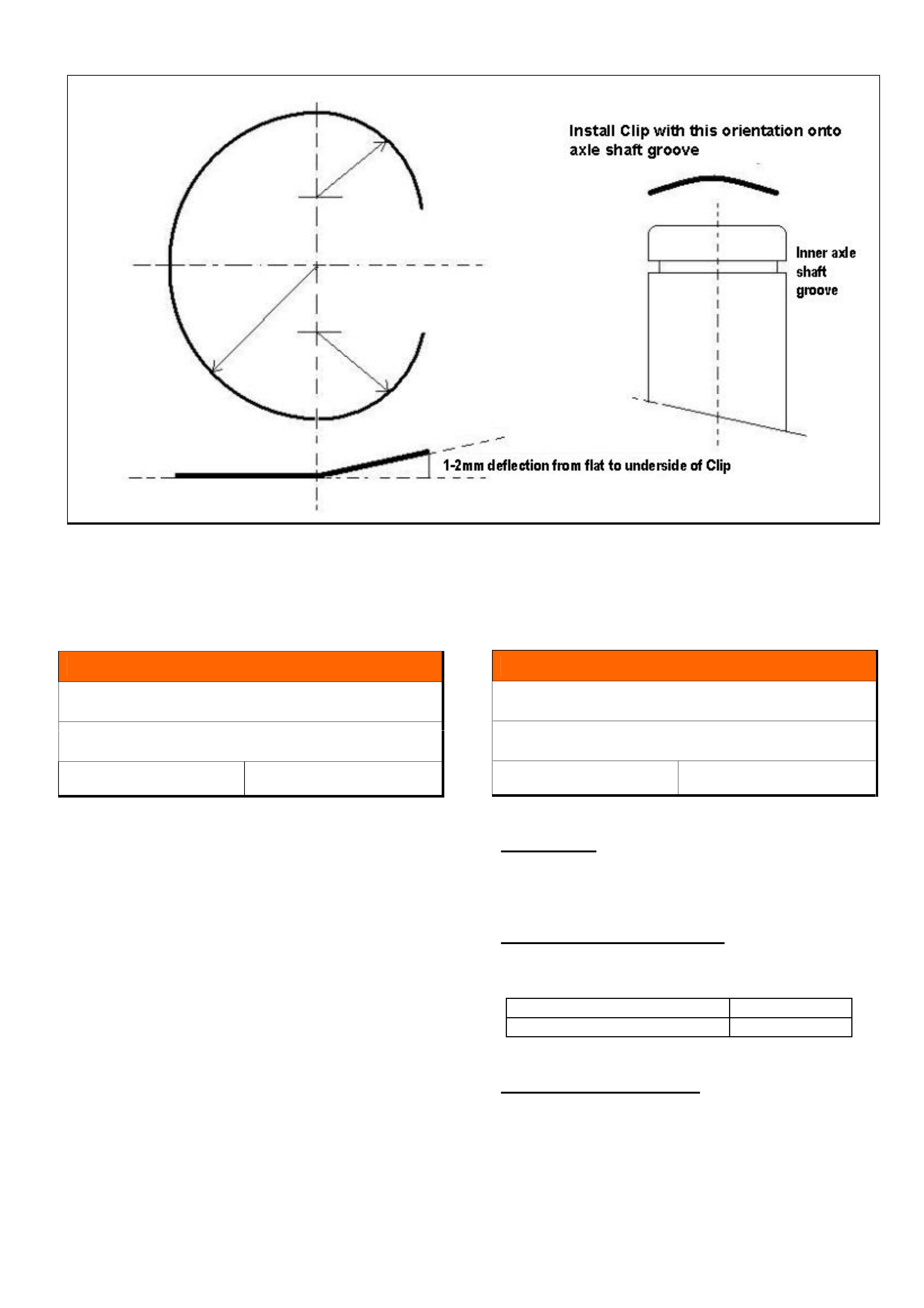
HOLDEN SERVICE TECHLINE _______________________________________________________________DECEMBER, 2004
12
Figure 1. Shows modification to Inner Axle shaft C clip
INFORMATION
Misfire With Traction Control Enabled
VZ & WL Gen 3 V8
Group 6C Ref. No. TL0830- 0411
Dealers have reported a misfire condition on above
models when loading up the engine while stationary
This is normal operation when traction control is
enabled as the system recognises this condition as a
traction control event.
Cylinders are disabled at random to reduce engine
torque and avoid wheel spin (unlike previous models
VT-VY).
INFORMATION
Service Reminder Intervals Incorrect
VZ & HFV6
Group OB Ref. No. TL0831- 0411
CONDITION
Service reminder set incorrectly to show 10,000km
service intervals instead of 15,000 km.
CORRECTION – Production
Instrument clusters with correct service reminder
intervals have been fitted to vehicles from:
ISOVIN: Built Date:
All vehicles built from 24/11/2004
CORRECTION – Service
Explain situation to customer when vehicle booked in
for service.
Rectify by reconfiguring instrument cluster with Tech
2 at next service opportunity.
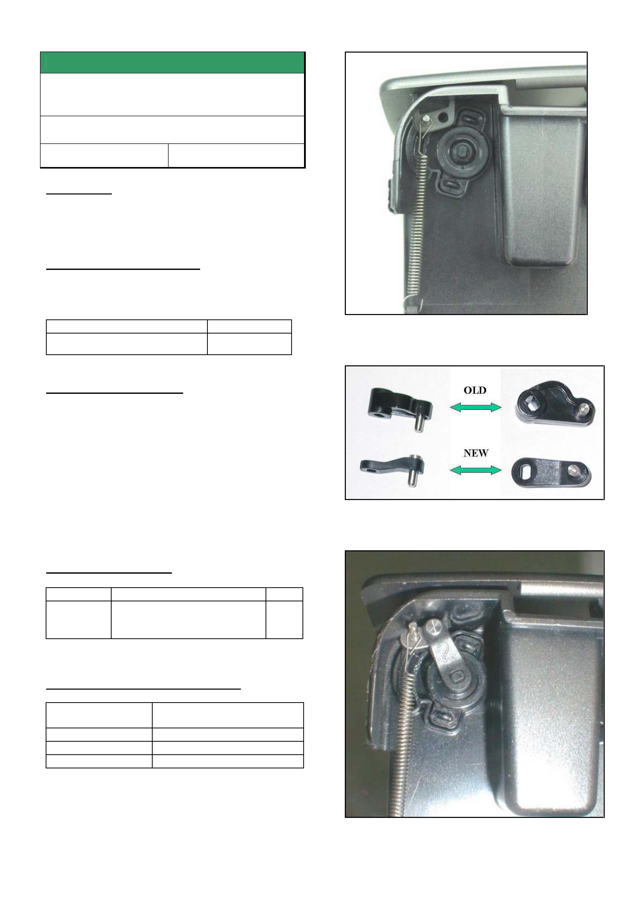
HOLDEN SERVICE TECHLINE _______________________________________________________________DECEMBER, 2004
13
SERVICE FIX
Phone Storage Compartment Lid Won’t
Open
VY, V2, VZ, WK, WL
Group 1 Ref. No. TL0716- 0411
CONDITION
Phone Storage Compartment Lid not functioning
correctly – one or both of linkage arms disconnecting
from damper.
CORRECTION – Production
Phone storage compartments with revised linkage
arms have been fitted to vehicles from:
ISOVIN: Built Date:
**********L327099 2 Sep 2004
CORRECTION – Service
Summary. Repair phone compartment instead of
replacing.
On any vehicle where the phone storage
compartment linkage arms have disconnected, (refer
figure 1) install revised arms to both sides.
The difference between the old and new arms is
shown in Figure 2.
Figure 3 shows the new arm installed.
PARTS INFORMATION
Part No.: Partfinder Name Qty
92148008 Rod – Front floor console
compartment door latch
release
2
WARRANTY CLAIM INFORMATION
Description Phone compartment
damper arm– Replace
Labour Op. No. C457500
Time 0.2 hr
Failure Code C0029 part missing
Figure 1. Shows door mechanism minus the arm.
Figure 2. Shows the old and new design arms
Figure 3. Shows new arm installed
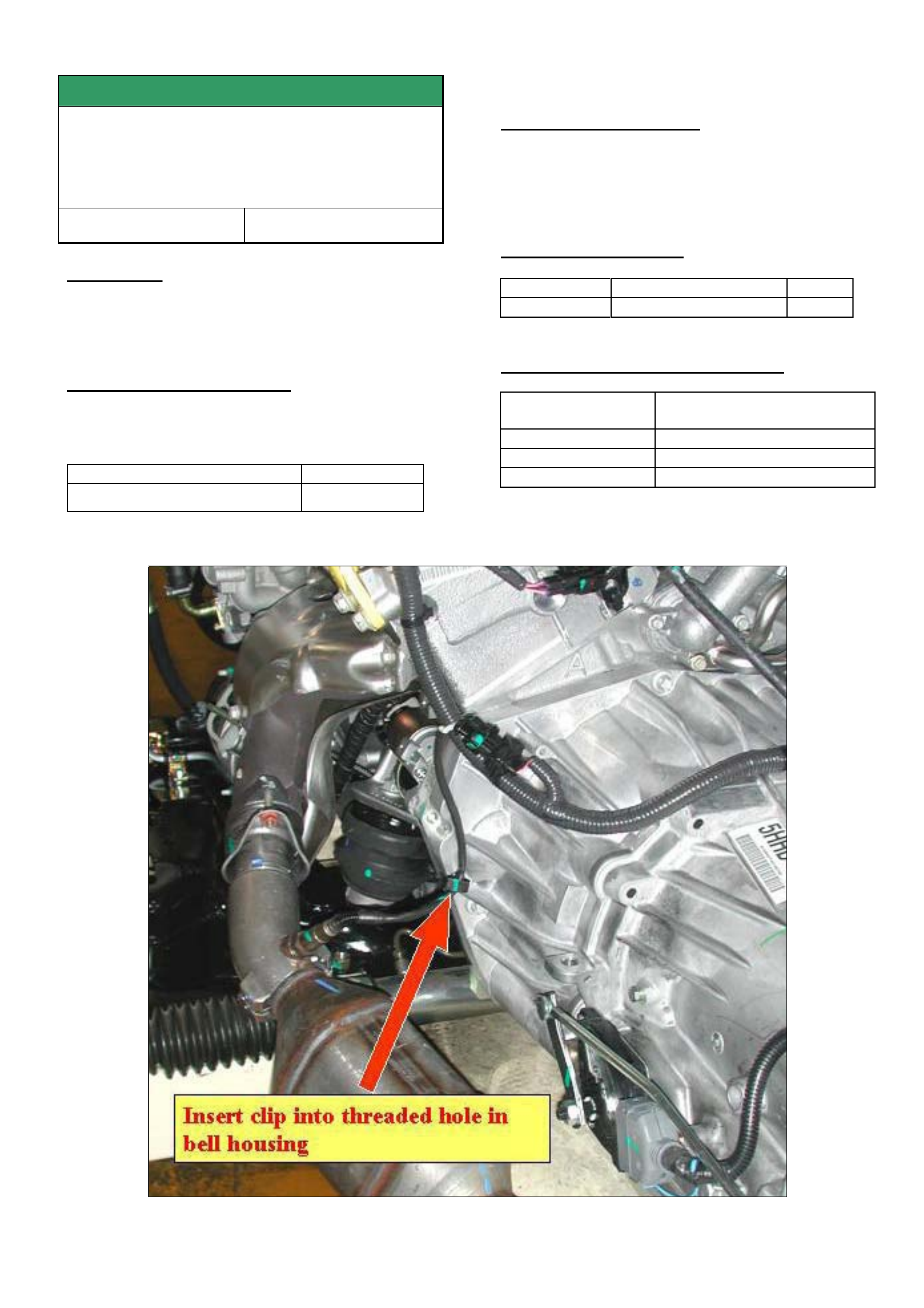
HOLDEN SERVICE TECHLINE _______________________________________________________________DECEMBER, 2004
14
SERVICE FIX
LHS O2 Sensor Wiring Insufficient
Clearance To Exhaust Heat Shield
VZ with HFV6 (175 kw)
Group 6C Ref. No. TL0819- 0411
CONDITION
On some vehicles the Left Hand O2 sensor wiring
harness may have insufficient clearance to the heat
shield (less than 30mm).
CORRECTION – Production
An additional clip was added to restrain the harness
on vehicles from:
ISOVIN: Built Date:
**********L358859 28/10/2004
CORRECTION – Service
On vehicles where the wiring harness is observed to
have less than 30mm clearance to the exhaust heat
shield install a clip as shown in figure 1.
PARTS INFORMATION
Part No.: Description: Qty:
92168425 Clip 1
WARRANTY CLAIM INFORMATION
Description Install LH O2 sensor wiring
restraining clip
Labour Op. No. J000764
Time 0.2 hr
Failure Code J0062 improper clearance
Figure 1. Add clip as shown to restrain LH O2 sensor harness.