
2
20
00
04
4
S
SE
ER
RV
VI
IC
CE
E
T
TE
EC
CH
HL
LI
IN
NE
ES
S
© 2006 GM Holden Ltd. A.B.N. 84 006 893 232
Service Department
A “HOLDEN” Product.
BRISBANE SYDNEY MELBOURNE ADELAIDE PERTH
For the latest and/or any missing Techline bulletins,
please refer to Holden Lionheart
HOLDEN SERVICE TECHLINE _____________________________________________________________FEBRUARY, 2004
15
SERVICE PROCEDURE
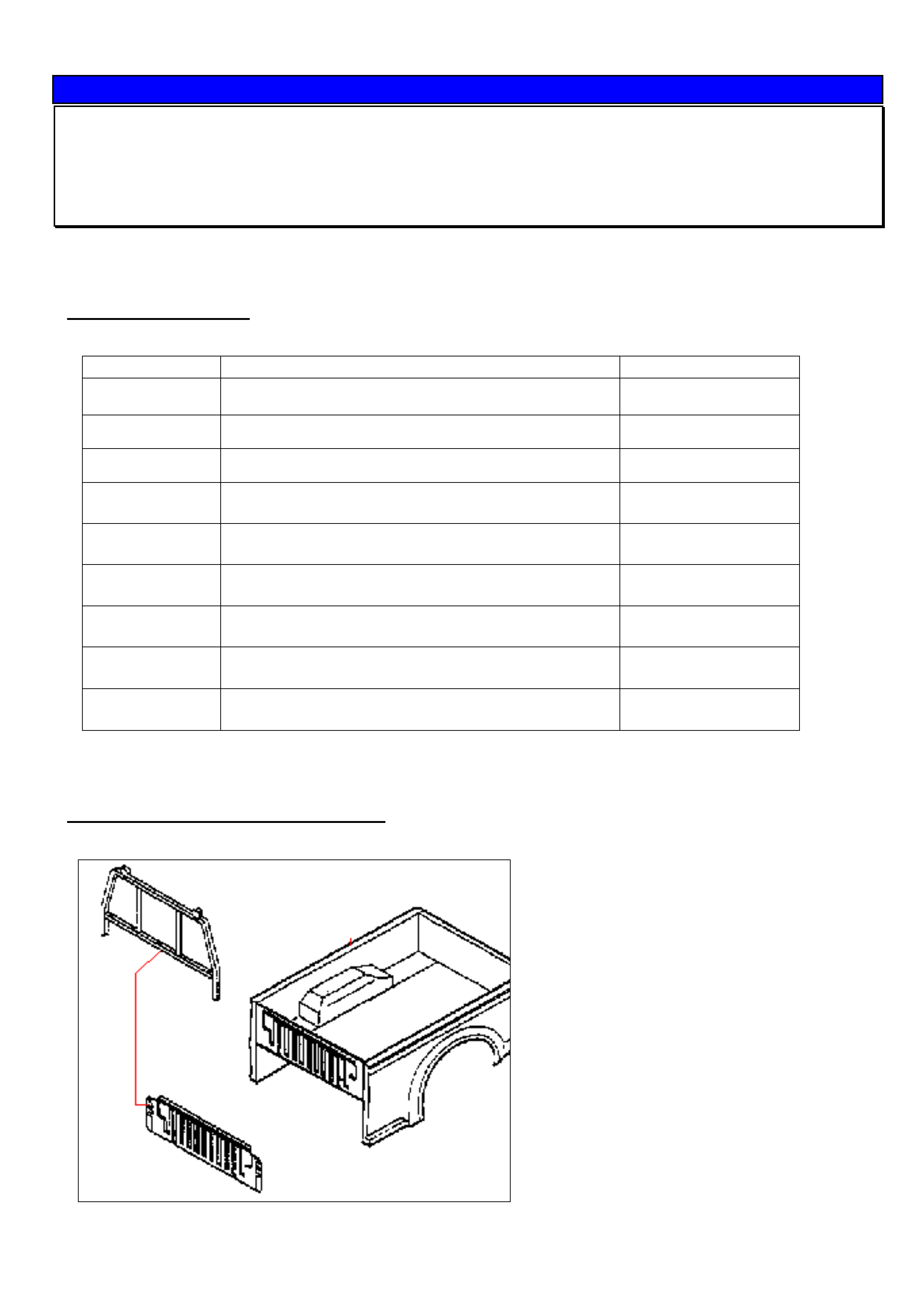
Fitting Instructions For Cargo Bar
RA Rodeo Space & Crew Pickup Models
(GROUP 01) TL0610-0401
The following instructions are provided in the event a customer requires a Cargo Bar Guard fitted to the rear body of
one of the above models.
PARTS INFORMATION
For vehicles that require a cargo bar fitted the following parts will be required.
P/N DESCRIPTION QUANTITY (PER CAR)
8973100752 FRAME - GUARD, REAR BODYSPACE/CREW CAB 1
8973526240 STOPPER - GUARD FRAME, REAR BODY
2
9091606060 WASHER - GUARD FRAME STOPPER
2
8944810220 BOLT - GUARD FRAME STOPPER, REAR BODY
- M6x45
2
8944814280 NUT - GUARD FRAME
- M6 FLANGE
2
0280806120 BOLT - GUARD FRAME
- M6x12 FLANGE
7
09440004 NUT - GUARD FRAME
- M6
5
8973106112 BOLT - REAR BODY MOUNT
- M12X50
- 4 (CrewCab)
- 6 (SpaceCab)
8973542010 BOLT - REAR BODY MOUNT
- M12X50
- 2 (CrewCab)
Also, PPG Multi Surface Epoxy Primer 410-39790 will be required. This is a 2-pack air-dry black paint available from
PPG Distribution centres in 1 and 4 litre containers. NOTE. An equivalent paint may be used.
Cargo Bar (Frame – Guard, Rear Body)
HOLDEN SERVICE TECHLINE _____________________________________________________________FEBRUARY, 2004
16
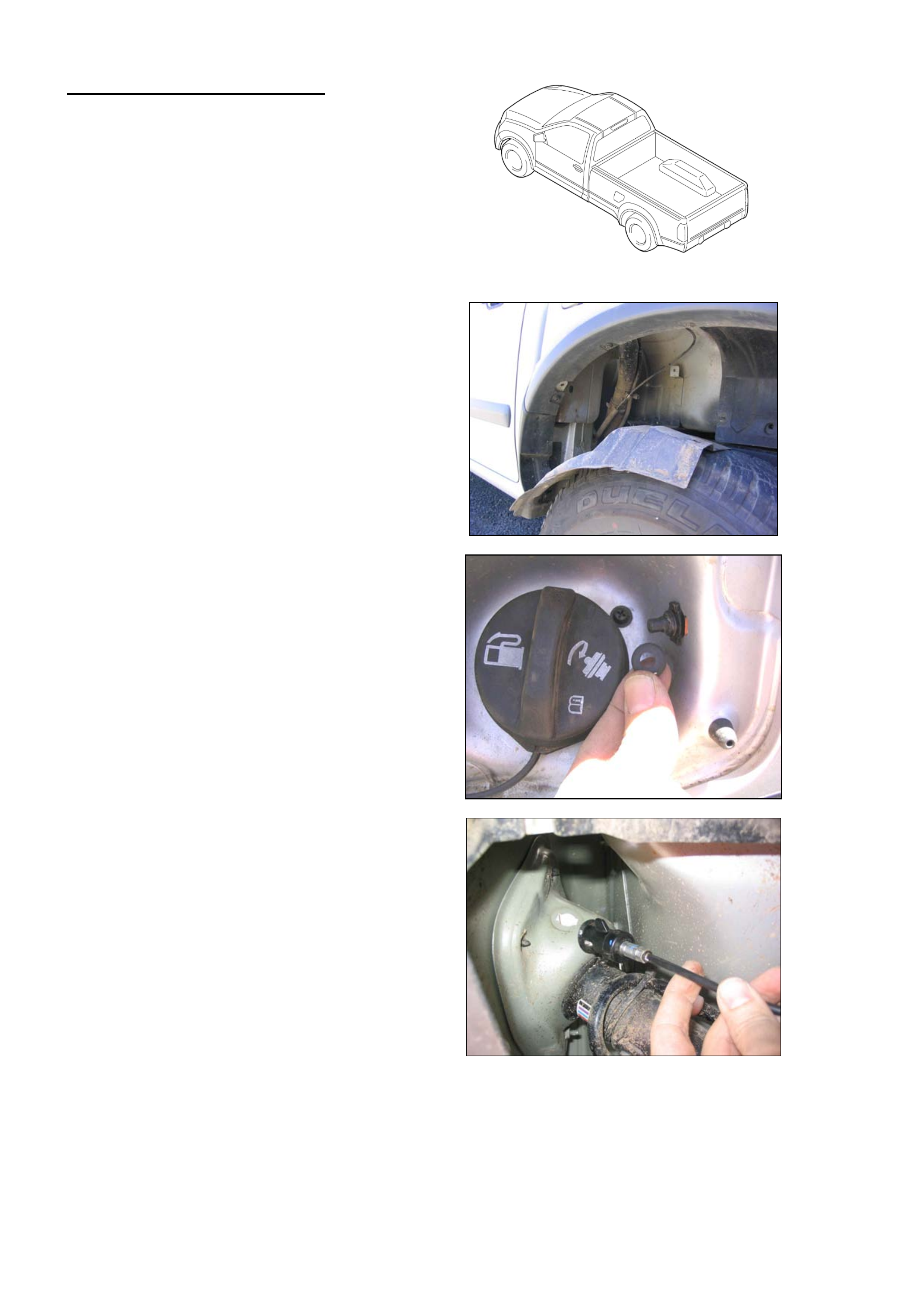
Rear Body Removal (Steps 1-6)
1. Disconnect negative battery terminal.
2. Disconnect rear combination lamp &
license lamp harness connector.
3. Remove rear wheelhouse extension
panels (LH & RH)
4. Disconnect fuel filler door release cable
assembly.
- Remove seal
- Twist and pull cable to remove
5. Disconnect fuel filler pipe and evaporator hose. Cover filler pipe with a rag to prevent
contamination of the fuel tank
HOLDEN SERVICE TECHLINE _____________________________________________________________FEBRUARY, 2004
17
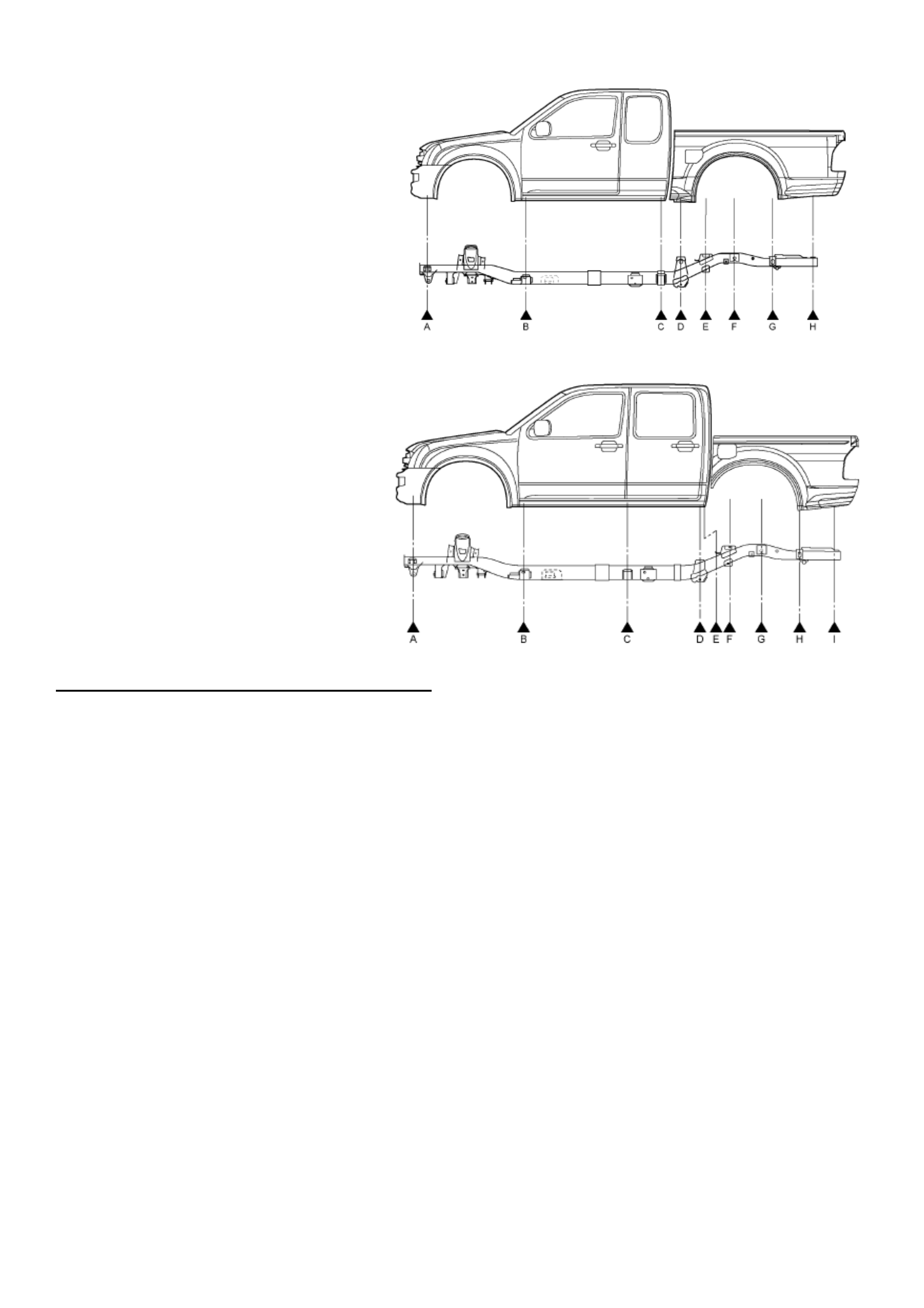
6. Unbolt rear body from frame
– Space Cab
- Undo bolts at points ‘D’, ‘G’ &
‘H’
- Lift rear body off the frame
and move
back from the cab to gain
access.
6. Unbolt rear body from frame
– Crew Cab
- Undo bolts at points ‘F’, ‘H’ &
‘I’
- Lift rear body off the frame
and move
back from the cab to gain
access.
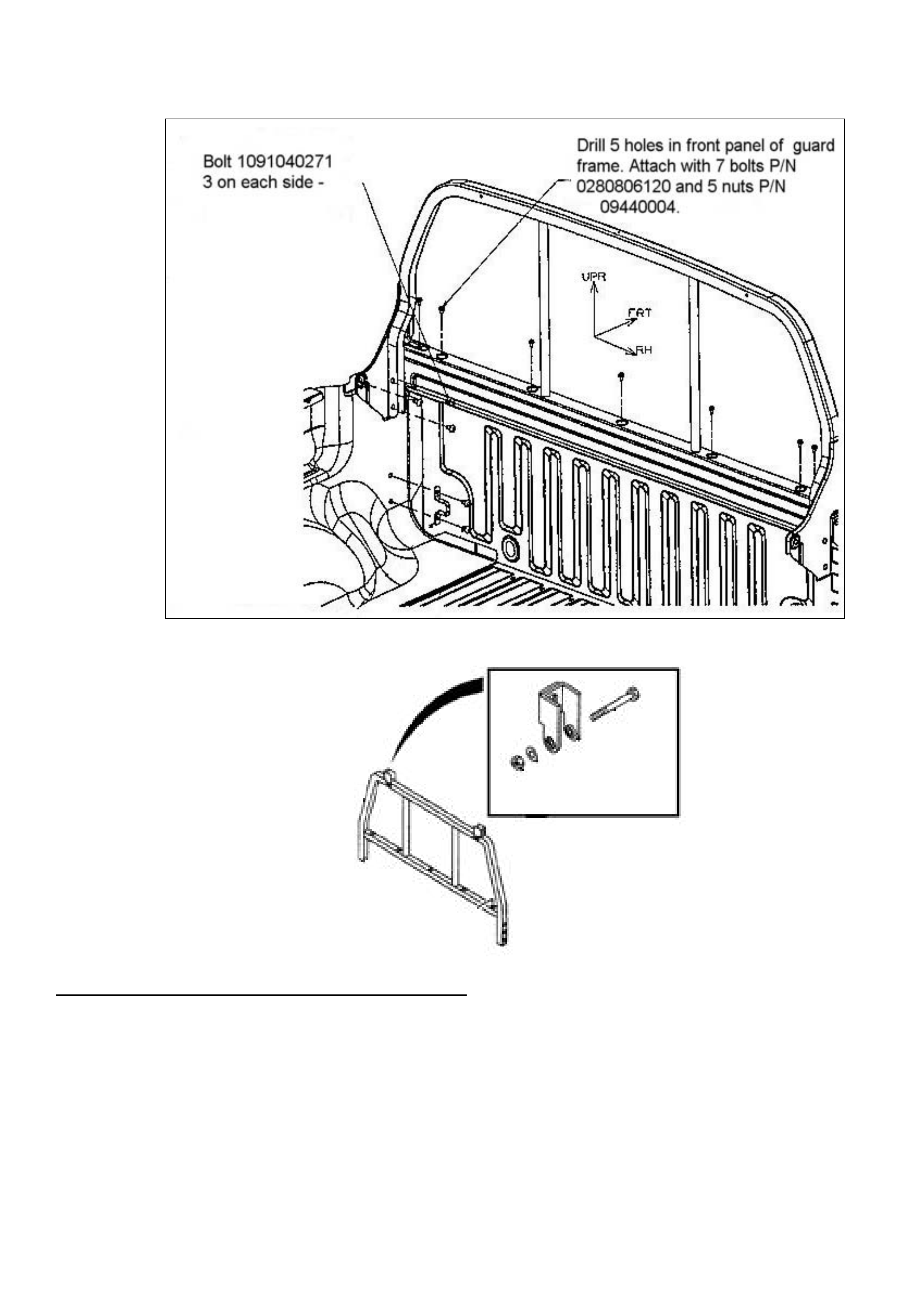
Guard Frame Installation – Refer Figures 1 & 2
1. Paint the following parts to match rear body colour:
• 1 x guard frame P/N 8973100752
• 2 x stopper – guard frame P/N 8973526240
Hint: The next steps show how to use the guard frame as a template for drilling the 5 holes in the front panel of the rear body.
2. Remove the 6 bolts P/N 1091040271 (3 on each side) that are already attached to the rear body.
3. Fit the guard frame P/N 8973100752 to the side walls of the rear body and fasten the 6 bolts with torque: 13.0 +/-
5.0 Nm.
4. Ensure that the Guard Frame is aligned correctly. Drill 5 holes with 7mm diameter drill in the centre of the 5 guard
frame bar holes.
5. Remove the Guard Frame from the rear body.
6. Apply PPG Multi Surface Epoxy Primer 410-39790 (or equivalent) to 5 holes just drilled. Ensure that surrounding
rear body area is protected from overspray.
7. Repeat step 3 to refit the Guard Frame.
8. Fit 2 bolts P/N 0280806120 to the outer holes on Guard Frame bar. Fit 5 bolts P/N 0280806120, and 5 nuts P/N
09440004. Torque all 7 bolts to 6.0 +/- 2.0 Nm
9. Fit the following parts to the top of the Guard Frame to construct the two guard frame stoppers. (Figure 2)
STOPPER - GUARD FRAME P/N 8973526240
WASHER - GUARD FRAME STOPPER P/N 9091606060
BOLT - GUARD FRAME STOPPER P/N 8944810220
NUT - GUARD FRAME P/N 8944814280
HOLDEN SERVICE TECHLINE _____________________________________________________________FEBRUARY, 2004
18
Figure 1.
Figure 2
Rear Body Installation Steps (Reverse of Removal)
1. Bolt rear body to frame.
NOTE: Discard used mounting bolts and replace with new ones.
Torque for all mounting bolts is 54 Nm(40 ft-lb)
2. Attach Fuel filler pipe and evaporator hose.
3. Connect fuel filler door release cable assembly
4. Attach rear wheel house extension panels
5. Connect the rear combination lamp & license Lamp connector.
6. Connect negative battery terminal
HOLDEN SERVICE TECHLINE _____________________________________________________________FEBRUARY, 2004
19
SERVICE INFORMATION
Laden Vehicle Trim Height Specification
RA Rodeo
(GROUP 4) TL0624-0401
The following information is provided to assist
Retailers when a customer complains of excessive
spring deflection when vehicle is loaded.
SERVICE RECOMMENDATION
To check spring deflection against specification
proceed as follows.
Step 1. Have the customer present the vehicle
to the retailership in the complaint condition (i.e.
loaded). Check all spring shackles/bushes for
condition. Rectify/replace as required.
Step 2. The vehicle must then be loaded to
achieve the Gross Vehicle Weight (GVW) Axle
Loadings as shown in following table. This will need
to be done on a vehicle weighing platform. It is
recommended to use sand bags to achieve the GVW
axle loadings.
Gross Vehicle Weight - Axle Loadings (kgs)
4x2 vehicle 4x4 vehicle
Front axle 1120 kg 1220 kg
Rear axle 1680 kg 1680 kg
Step 2 After achieving the above front and
rear axle loads, the dimensions as shown in the
following figures 1, 2, 3, & 4 can now be measured.
Step 3. Compare measurements taken in step
2 to those in Figure 5. Remember to take into
account the tolerances (+/-) on the specifications.
Also, the bump stop clearances are given for
reference only. If the measured vehicle trim heights
are below the specifications given, the spring
deflection is greater than production specification.
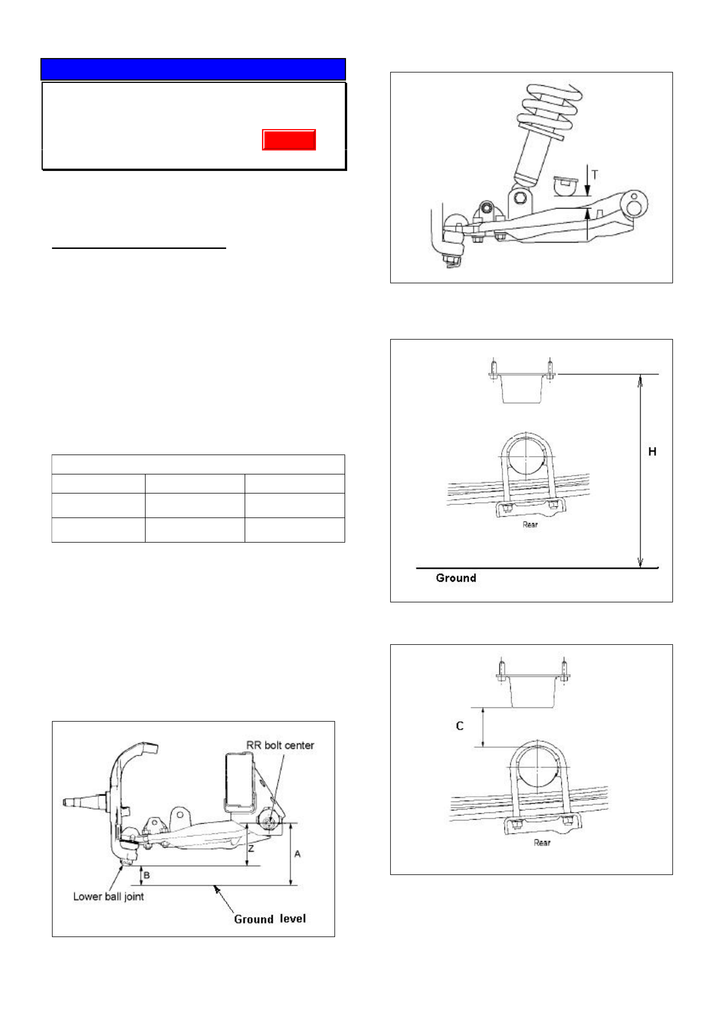
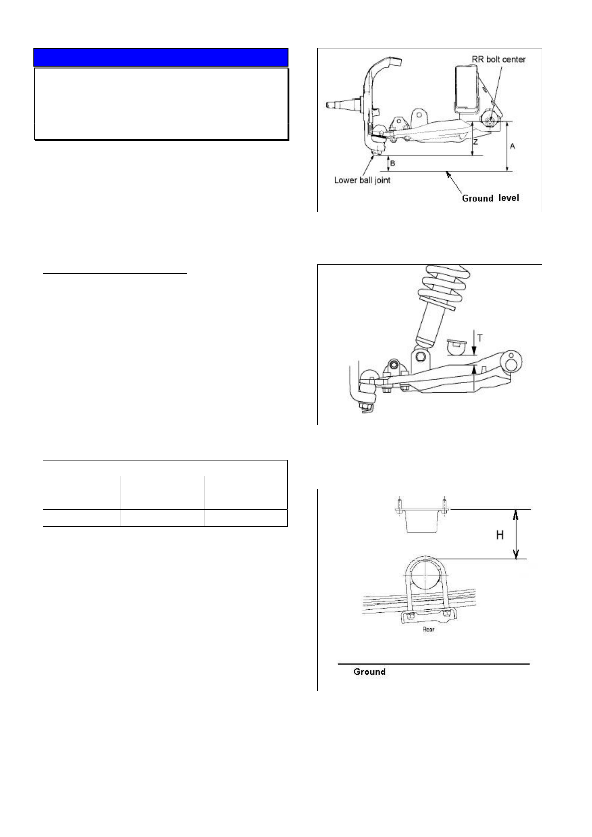
Figure 1. Front Trim height “Z” = A - B
Figure 2. Front bump stop clearance T (for
reference only)
Figure 3. Rear bump stop mount height “H”
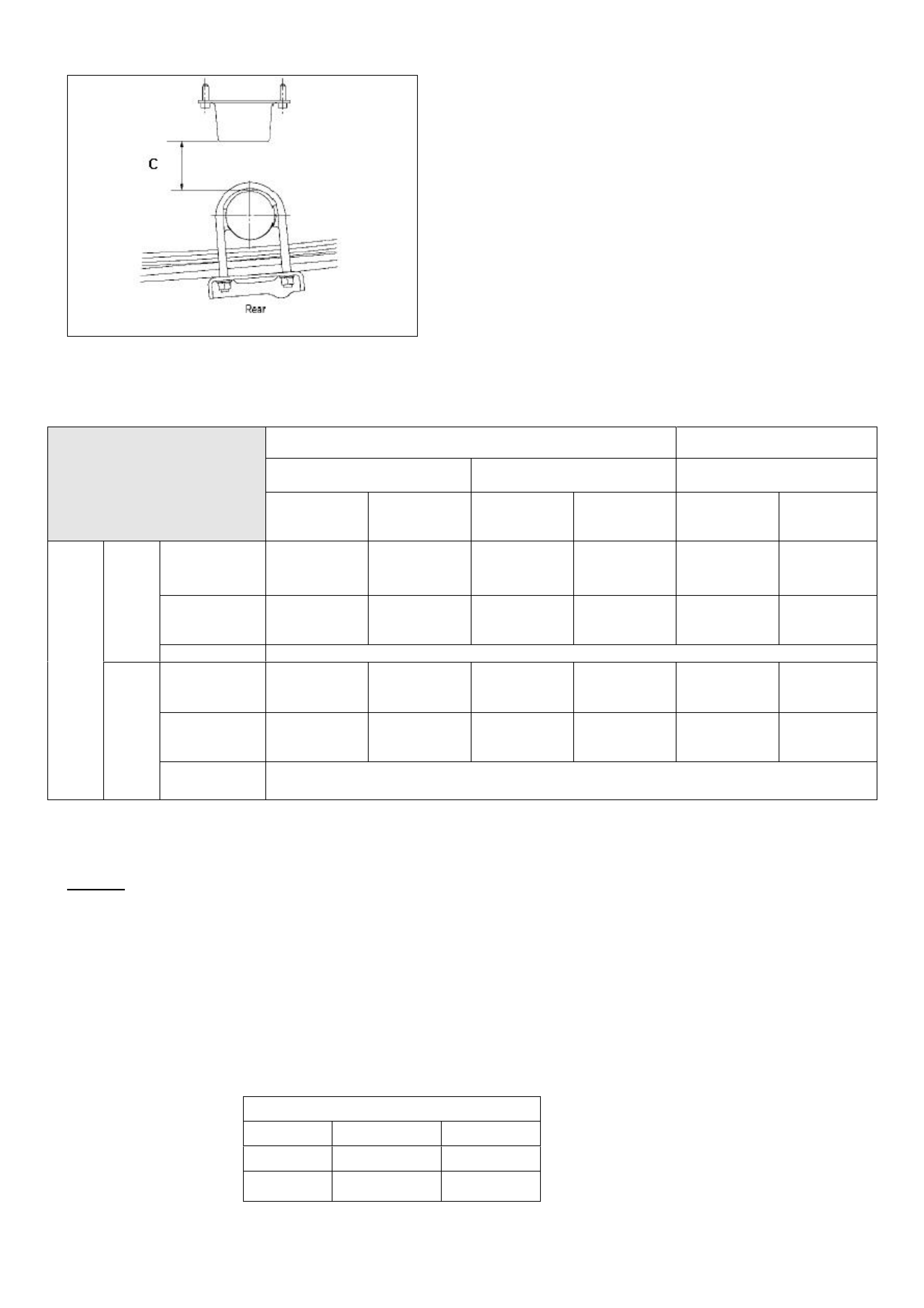
Figure 4. Rear bump stop clearance “C” (for
reference only)
Update
HOLDEN SERVICE TECHLINE _____________________________________________________________FEBRUARY, 2004
20
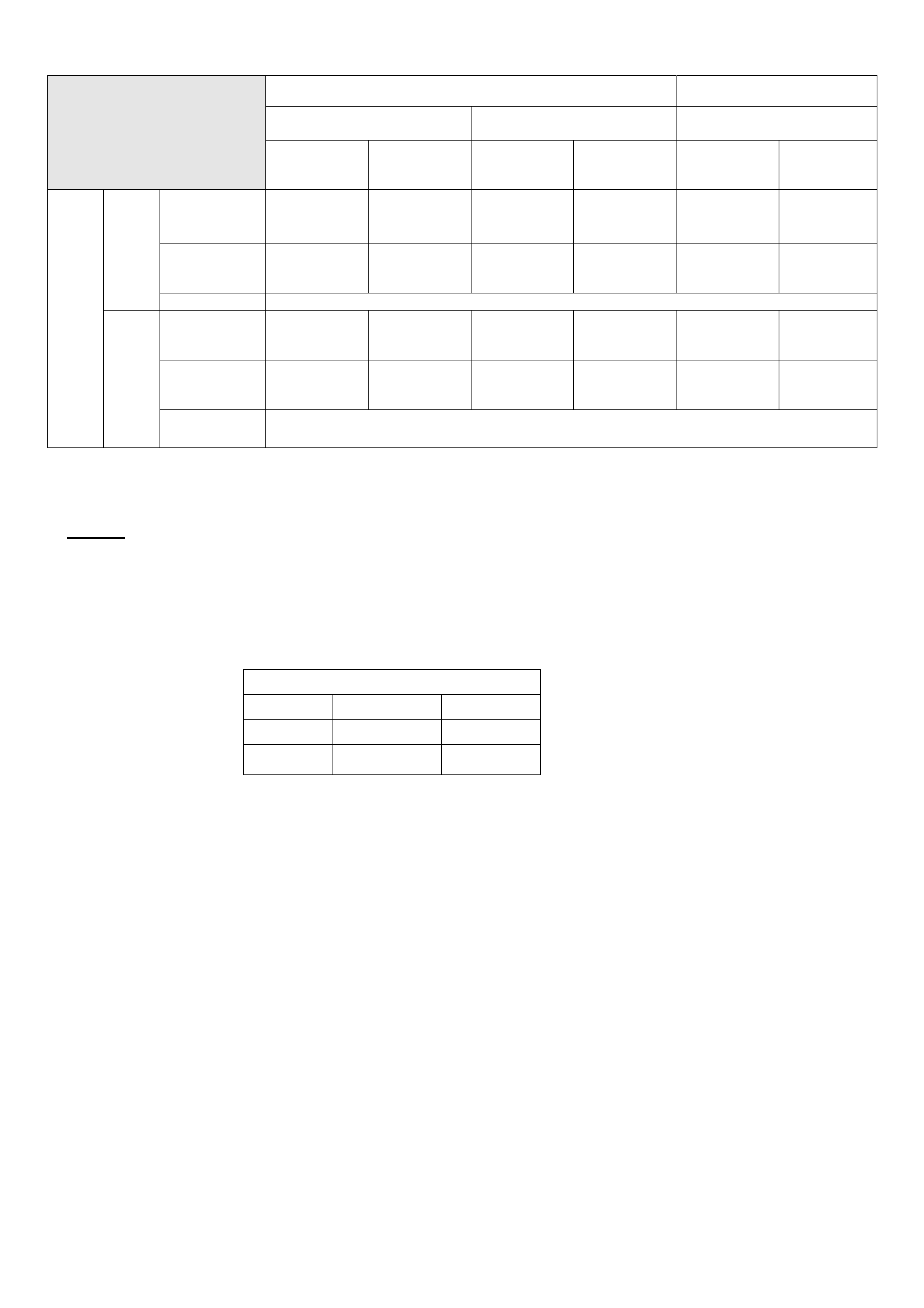
4 x 2 4 x 4
4JH1 & 6VE1 C24SE 4JH1 & 6VE1
RA Rodeo
Vehicle Trim Height
Specifications @ GVW Standard
Rear springs
(5 leaves)
HD
Rear springs
(7 leaves)
Standard
Rear springs
(5 leaves)
HD
Rear springs
(7 leaves)
Standard
Rear springs
(5 leaves)
HD
Rear springs
(7 leaves)
Trim Height
Z 83.2 83.2 60.8 60.8 108.0 108.0
Bump stop
clearance
T (Ref only)
17.8 17.8 9.4 9.4 17.0 17.0
Front
Tolerance mm +/- 7
Bump stop
mount height
H
446.8 433.7 446.8 433.7 490.5 478.4
Bump stop
clearance
C (Ref only)
22.5 9.4 22.5 9.4 21.6 9.5
GVW
Rear
Tolerance
(mm) +/- 6
Figure 5. RA Rodeo -Trim Height Specifications at Gross Vehicle Weight. (All dimensions are in mm).
NOTES.
• Front Trim Height “Z” and Rear Bump stop mount height “H” are the critical dimensions to be looked at
when assessing the condition of the vehicle springs.
• Front ( “T” ) & Rear ( “C” ) bump stop clearance should be used as reference data only.
• All measurements should be taken with the vehicle on a flat surface
• Vehicle weight distribution must comply with the front and rear axle weights for GVW loading as per
following table.
Gross Vehicle Weight - Axle Loadings (kgs)
4x2 vehicle 4x4 vehicle
Front axle 1120 kg 1220 kg
Rear axle 1680 kg 1680 kg
• The above information will be available in the next update to LCRV SIP (i.e. version 4.6)
HOLDEN SERVICE TECHLINE _____________________________________________________________FEBRUARY, 2004
21
SERVICE PROCEDURE
Throttle Position Sensor Replacement
UBS – Jackaroo Diesel (4JX1)
(GROUP 6C) TL0585-0401
Previously, the TPS was not available as a separate
component. This required the complete throttle body
assembly to be replaced if the TPS required
replacing.
SERVICE PROCEDURE
1. Remove intake throttle body from intake manifold
2. Clean the throttle body of any carbon sludge.
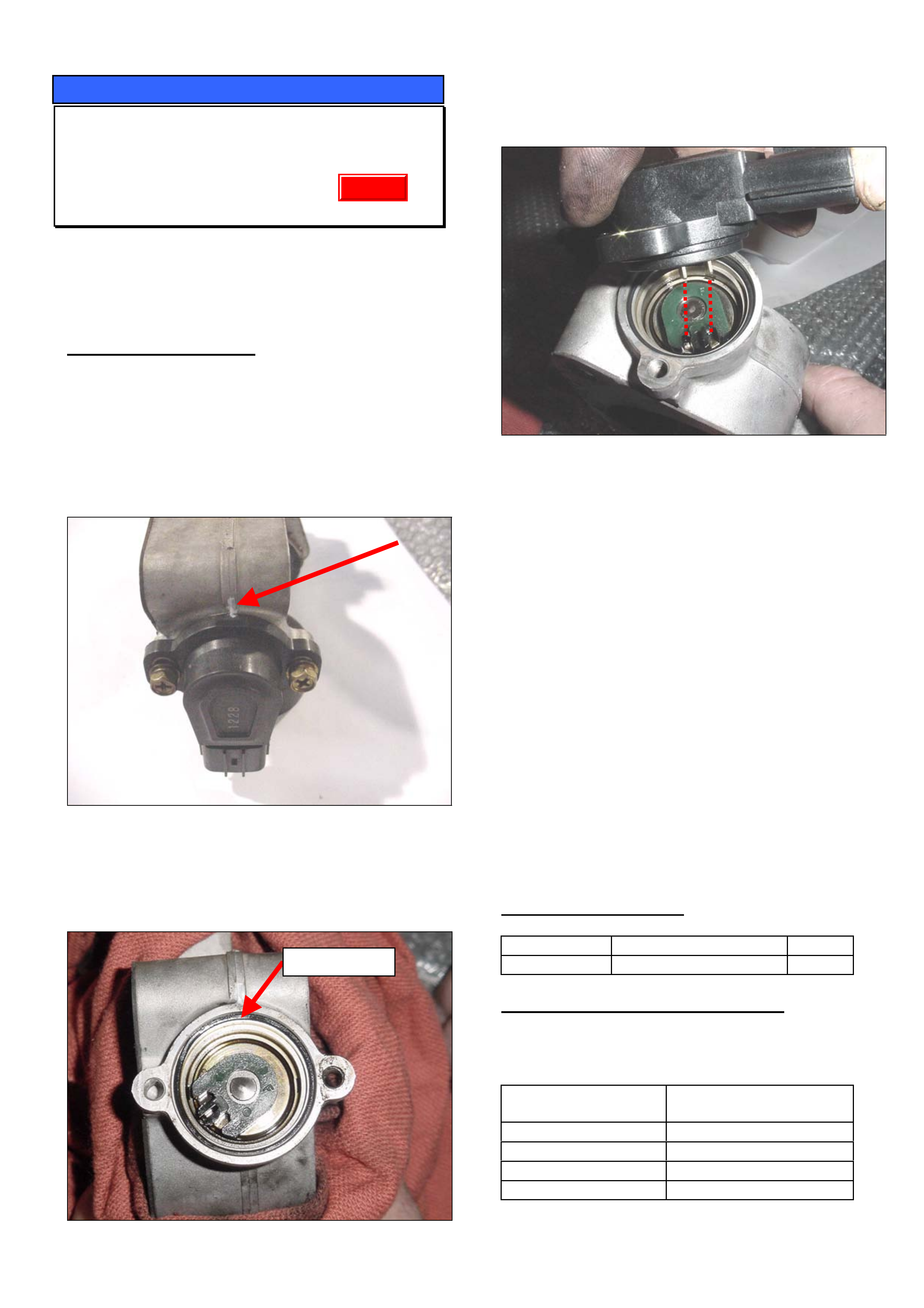
3. Mark the throttle body, with a marker pen, in a
position that can act as a reference on both the
new and old sensor e.g. casting mark (Fig. 1).
Figure 1.
4. Remove the TPS From the Throttle Boby.
5. Clean inside the TPS mount and replace the o-ring
seal.
Figure 2
6. Fit a new TPS to the throttle body and torque
screws to 3.0 Nm. Ensuring that TPS teeth are
engaged correctly as shown in figure 3.
Figure 3.
7. Reinstall the throttle body to the vehicle.
8. Connect Tech-2 and enter the correct vehicle and
engine information:
• Select F3: Miscellaneous Tests function.
• Select F3: Throttle position Motor Control function.
• Scroll down until Throttle Position Sensor
Voltage and Throttle Position Steps are displayed.
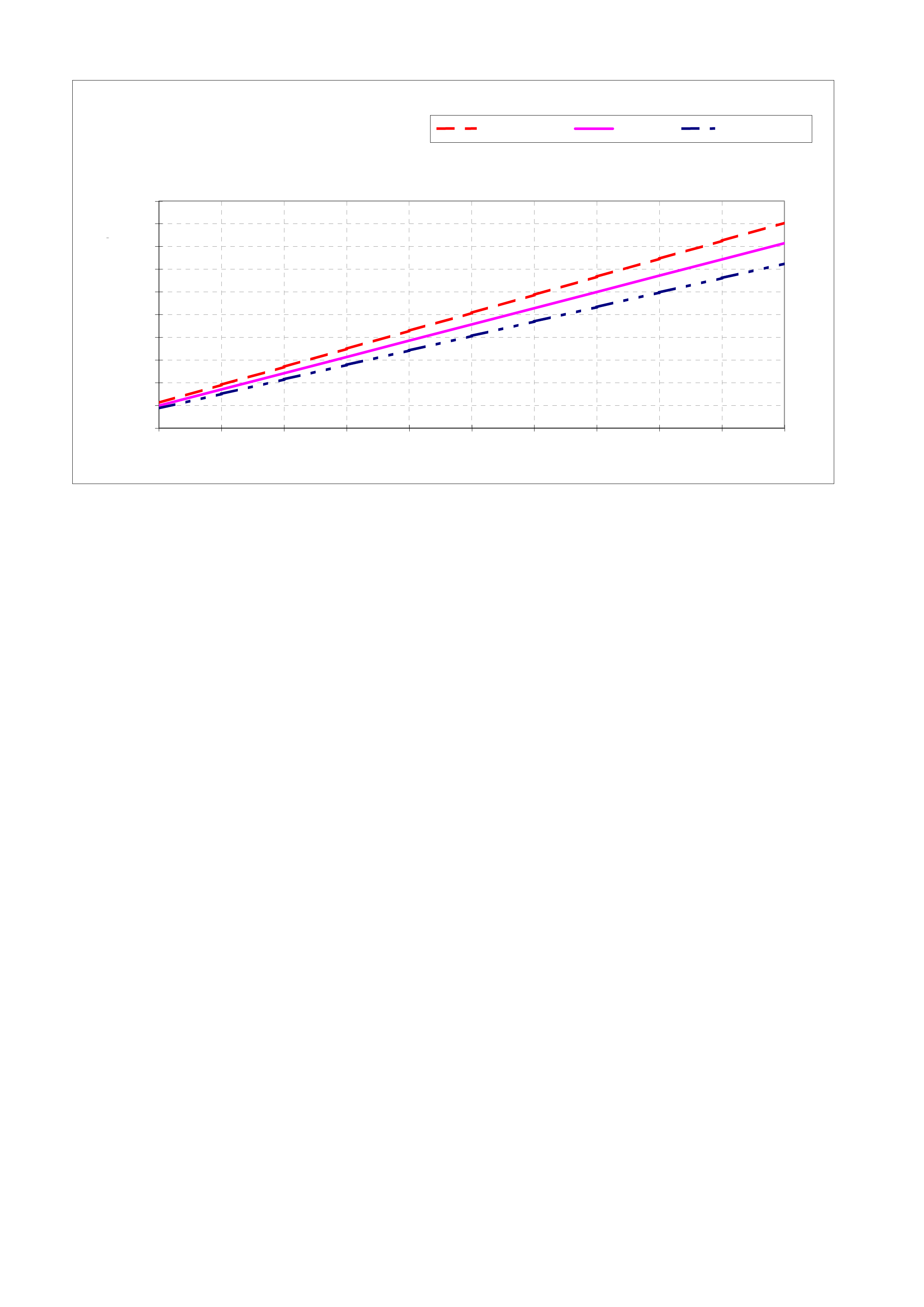
9. Verify the Throttle Position Sensor Voltage at each
valve step is within the threshold values shown in
graph 1 below.
10. If the values are outside the threshold range,
adjust the TPS so that they fall within the
threshhold range.
11. Reassemble the vehicle and check the complaint
has been rectified.
PARTS INFORMATION
Part No.: Description: Qty:
8973728510 Sensor, TPS 1
WARRANTY CLAIM INFORMATION
If the vehicle is still covered by new vehicle warranty
use the information below:
Description Sensor, Throttle
Position - Replace
Labour Op. No. J637400
Time 0.5 hr
Failure Code 50
Failure Code NOW J0050
O-rin
g
Seal
Update
HOLDEN SERVICE TECHLINE _____________________________________________________________FEBRUARY, 2004
22
Threshold Value at Each Step of Throttle Valve
0.95
1.35
1.75
2.14
2.54
2.94
3.33
3.73
4.13
4.52
0.75
1.07
1.39
1.71
2.03
2.35
2.67
2.99
3.31
3.62
0.56
0.44
0.00
0.50
1.00
1.50
2.00
2.50
3.00
3.50
4.00
4.50
5.00
012345678910
T hro ttle Valve Step
TPS Output Signal Voltag
e
Upper Limit Median Lower Limit

HOLDEN SERVICE TECHLINE __________________________________________________________________MARCH, 2004
5
INFORMATION
Security Code
YG
(GROUP 0B) TL0662-0402
The vehicle security code for all YG Cruze is the
same.
Technicians often request the security number
through the Security Information request procedure
only to be advised by Security Department that the
number is available on LCV SIP.
The number is located in System Electrical, Section
8G / 5 / page 24.
INFORMATION
SPS Programming and Linking
All Models
(GROUP 0B) TL0664-0402
TAS receive many calls from retailer technicians who
run into problems when trying to perform the
"Program Immobiliser Function" or PCM to BCM link.
Please be aware that if you are installing a new
PCM/ECU you must do SPS programming before
carrying out the above.
This is only required for new PCMs/ECUs.

HOLDEN SERVICE TECHLINE __________________________________________________________________MARCH, 2004
6
DIAGNOSIS HINT
Erratic Tachometer Operation, and/or
4WD Not Operating (if fitted)
RA Petrol or Diesel
(GROUP 12) TL0649-0402
CONDITION
Erratic tacho or speedo operation and/or no 4WD
operation (if 4wd equipped).
CAUSE
This condition may be caused by a blown or missing
fuse located at Position 2 in the interior fuse box.
CORRECTION
Verify that the ABS fuse at position 2 in interior fuse
box isn’t blown / missing.
NOTE: Vehicles without ABS require this fuse to be in
place for correct instrument cluster and 4WD
operation.
SERVICE PROCEDURE
Throttle Position Sensor Replacement
UBS – Jackaroo Diesel (4JX1)
(GROUP 6C) TL0585-0401
There has been an update to this Techline which was
previously published in Issue 1, 2004.
It has been updated by highlighting the fact that when
a new sensor is ordered, it also comes with a new O-
ring and sensor attaching screws. These parts do not
need to be ordered separately .
NOTE. The updated techline is now available on the
Holden Lionheart Portal which is accessed via your
Retailer’s PC.
The updated techline number is TL0585A-0402
Update
HOLDEN SERVICE TECHLINE __________________________________________________________________MARCH, 2004
10
SERVICE FIX
4WD Transfer Case Control Module
(TCCM) “Lock- up”
RA 4WD
(GROUP 4) TL0623-0402
CONDITION
Complaints have been received of Transfer Case
Control Module (TCCM) “lock-up” – e.g. the CHECK
4WD lamp on the instrument panel stays on to
indicate a 4WD selection malfunction. The condition
appears to occur at random.
CAUSE
The above condition is due to the TCCM
engagement signal “recognition” timing being too
short – these are the vehicle’s electrical system
feedback or monitoring signals that define correct
operation of the 4WD selection components.
CORRECTION in PRODUCTION
Revised TCCM’s with increased recognition timing
were introduced into production from:
ISOVIN: Built Date:
MPATFS77H4H510581 August, 2003
CORRECTION in SERVICE
Summary: Check electrical circuit integrity, correct
any problems. Fit a new TCCM if required.
Step 1.
Vehicles that suffer from “cannot select 4WD”, or
“module lock-up” when 4WD Hi or Low is being
selected; may have loss of continuity of one or more
of the limit switch circuits to the transfer case
actuator, or to the module’s return control. These
vehicles should have continuity checks of the
connections to TCCM, Trans. Case Actuator circuits
LS1, LS2, LS3, LS4 as described in Techline
published in June, 2003 titled “4WD Selection &
Diagnosis” . These checks are also in current LCV
SIP.
IMPORTANT. Any electrical faults must be
corrected, as only resetting or replacing the TCCM
will allow the customer complaint to re-occur, as the
root cause has not been addressed.
Step 2.
If all connections/circuits prove to be OK and the
condition is still present, replace the TCCM with later
TCCM, 8973684490. This module features a greater
internal time delay, allowing the module to better
monitor the return signals from the 4WD selection
components.
PARTS INFORMATION
Part No.: Description: Qty:
8973684490 TCCM Asm. 1
WARRANTY CLAIM INFORMATION
Warranty Administrators please note – the following
standard Labour Operation number has been
released for this module.
Failure Code 37 is recommended for use when
replacing as per this Techline instruction.
Description Transfer Case Control
Module Asm – R & R,
Replace or Reset
Labour Op. No. K651800
Time 0.4 hr
Failure Code 37 – Poor Engagement
Failure Code NOW K0037
Understanding 4WD Selection Criteria
To help technicians understand the 4WD selection
criteria, a Service Techline was released in June,
2003, Issue 6, page 11. Information in that Techline
has also been reproduced in Owner Handbooks and
the LCV SIP.
Customers who complain they have difficulty in
selecting 4WD, or may have “lock-up” occur may not
fully understand the 4WD selection criteria. It may
be helpful to show them this information.

HOLDEN SERVICE TECHLINE __________________________________________________________________MARCH, 2004
11
INFORMATION
Isuzu Tech 2 Software Downloading from
TIS 2000
RA
(GROUP 0B) TL0663-0402
With the introduction of RA Rodeo, LCV Tech 2
software is downloaded from TIS 2000 to the 10
megabite PCMCIA card.
When downloading the LCV software, Technicians
need to have the 10 Meg card in the slot closest to
the screen and select "Isuzu - General Export"
from the menu in the software download screen as
shown below.
Select Dealer Software Type:
Holden
Isuzu–General Export, North America (Isuzu Based Veh), Domestic
Isuzu NA (GM Based Veh.) – North America
Isuzu NA (Isuzu Based Veh.) – North America
Opel/Vauxhall

HOLDEN SERVICE TECHLINE __________________________________________________________________APRIL, 2004
5
DIAGNOSIS HINT
Engine Poor Performance After Driving
Through Water Or Washing Engine
RA with 3.0L 4JH1 Diesel Engine
(GROUP 6C) TL0677-0403
PROBLEM DESCRIPTION
Complaint of poor engine performance or lack of
power on RA Rodeo fitted with 3.0L 4JH1 diesel
engine after driving through water or washing the
engine.
This can be caused by dust in the Electrical Vacuum
Regulating Valve (EVRV) getting wet and blocking
the filter in the valve.
The EVRV valve is located in the engine
compartment on the RHS guard area and is used to
control the operation of the EGR valve.
SERVICE RECTIFICATION
Verify correct operation of the EGR valve. If the
EGR valve is not operating correctly, remove the
EVRV, and visually inspect for dust or water entry to
the valve. If the valve is found to be contaminated it
must be replaced.
TIP
For testing purposes, the vacuum line to the EGR
valve can be removed and plugged for duration of
test drive to confirm if it is the EGR system that is
causing the low performance.
THIS HOSE MUST BE RECONNECTED AFTER
THE TEST.
DIAGNOSIS HINT
Engine Poor Performance Due to
“Oil type” Air Filters
RA / TF with 3.0L 4JH1 Diesel Engine
(GROUP 6C) TL0678-0403
PROBLEM DESCRIPTION
Complaint of poor engine performance or lack of
power on RA/TF Rodeo fitted with 3.0L 4JH1 diesel
engine.
This condition can be caused by the use of non
approved foam oil-type air filters being used in place
of the specified paper element type air filter. The oil
can be drawn from the foam air filter and
contaminate the Mass Air Flow (MAF) sensor.
DTC’s may or may not be set.
SERVICE RECTIFICATION
Retailers are reminded that Holden does not
recommend the fitting and use of non specified foam
oil type air filters in the above models.
If fitted, these filters should be removed and replaced
with the recommended paper element type filter.
Remove the MAF from the vehicle, clean with a
cleaning solution such as throttle body cleaner and
refit to the vehicle.
If engine performance is still poor, a new MAF will
need to be fitted after confirming that the MAF is
damaged.
NOTE 1: The above non approved foam oil type air
filter must not be confused with the approved foam
pre-cleaner that can be fitted as described in Service
Techline issue 11, 2003, page 18.
NOTE 2: The above rectification work is not covered
by new vehicle warranty.
Update

HOLDEN SERVICE TECHLINE __________________________________________________________________APRIL, 2004
6
INFORMATION
Holden Contacts and Procedures
(GROUP OB) TL0679-0403
This techline summarises some of the Holden
contact procedures and gives a quick reference
guide for contact numbers.
Security information.
To obtain security information a completed security
information request form must be faxed through to
the security information department, as security
information cannot be given out by phone. TAS does
not process security information requests. Please
ensure you have the latest security information
request form, which is available on SIP. Contact
details are listed below. There can be up to a 4-hour
turn around on requests however if the information
needs to be obtained from overseas, it may take up
to 24 hrs. Do not phone the security information
department unless you have not received a response
in the normal turn around time. For further
information please refer to ADL 63/99.
Parts inquiries and information
If any information or assistance is required in regards
to part numbers or Partfinder, please refer to the
Holden Help section in Partfinder.
Warranty Authorisation and enquiries
Warranty can only be authorised by your Aftersales
District Manager. Labour times information is
available on SIP or from the warranty department.
For any other warranty inquiries please contact
Warranty Administration.
TAS
Technical Assistance Service (TAS) is a service
provided by Holden to assist Holden Dealers in
problem resolution.
TAS operating hours are:
Monday to Thursday 8.30am – 8.00pm and Friday
9.30am – 5.00pm Melbourne time. Contact to TAS
must be made by a Nominated Contact as outlined in
Section 5 of the TAS procedures manual. All
techlines, dealer letters and service information must
be checked prior to contacting TAS. The Nominated
Contact must not contact TAS until he/she has been
fully involved with the faulting vehicle and all Dealer
expertise has been exhausted. Problems should be
escalated through the Dealership to the senior
technician/foreman before contacting TAS.
TAS cases must be updated or closed within 30 days
unless a Dealer is waiting on a service fix to be
provided. It is the Dealers responsibility to update
cases. All cases should be recorded in the TAS
procedures manual, which should be referred to prior
to contacting TAS. Please note that an electronic
copy of the TAS procedures manual is also available
on passenger SIP.
Under no circumstances are TAS or other Holden
contact details to be supplied to customers or
independent repairers. TAS is a service restricted to
assisting Holden Dealer service departments.
Quick reference contact numbers
Air International Ph 1800 673 716
Australian Arrow Ph 03 9785 0792
Blaupunkt/Bosch Ph 1300 307 036
Clarion Ph 03 8558 1115
Fax 03 9551 0377
Customer Assistance Ph 1800 033 349
Dana Ph 02 9892 9237
Fax 02 9892 9310
www.spiceraxle.com.au
Delphi Ph 1800 335 777
Eurovox Ph 03 9237 0800
Fujitsu Ten Ph 03 9646 6008
Holden Assist Ph 1300 880 088
HSV Ph 03 9265 9500
Infomedia Ph 1800 810 103
Panasonic Ph 02 9986 7635
Petro-Ject Ph 02 9890 5701
Ph 02 9890 5244
Philips/Siemens-VDO Ph 1800 335 282
Salmat Ph 03 9358 2900
Security Ph 03 9647 2001
SPX Australia Ph 03 9544 6222
TAS Ph 1800 033 417
Fax 03 9647 2495
Warranty Ph 03 9647 1972
Ph 03 9647 2401
Ph 03 9647 1970
Update
HOLDEN SERVICE TECHLINE __________________________________________________________________APRIL, 2004
11
SERVICE FIX
Low Clutch Engagement Point
YG Cruze with M/T
(GROUP 7A) TL0653-0403
CONDITION
Customer complains clutch engagement point is
lower than normal.
Technicians should confirm condition by checking
clutch pedal freeplay adjustment as per LCV SIP
Section 7C-Clutch/Section 3.1-Clutch Cable
CAUSE
Clutch cable adjusting nut loosens.
CORRECTION - Production
Lock nut added to clutch cable from:
ISOVIN: Built Date:
JSAGHY81S00112181 Mar 2003
CORRECTION - Service
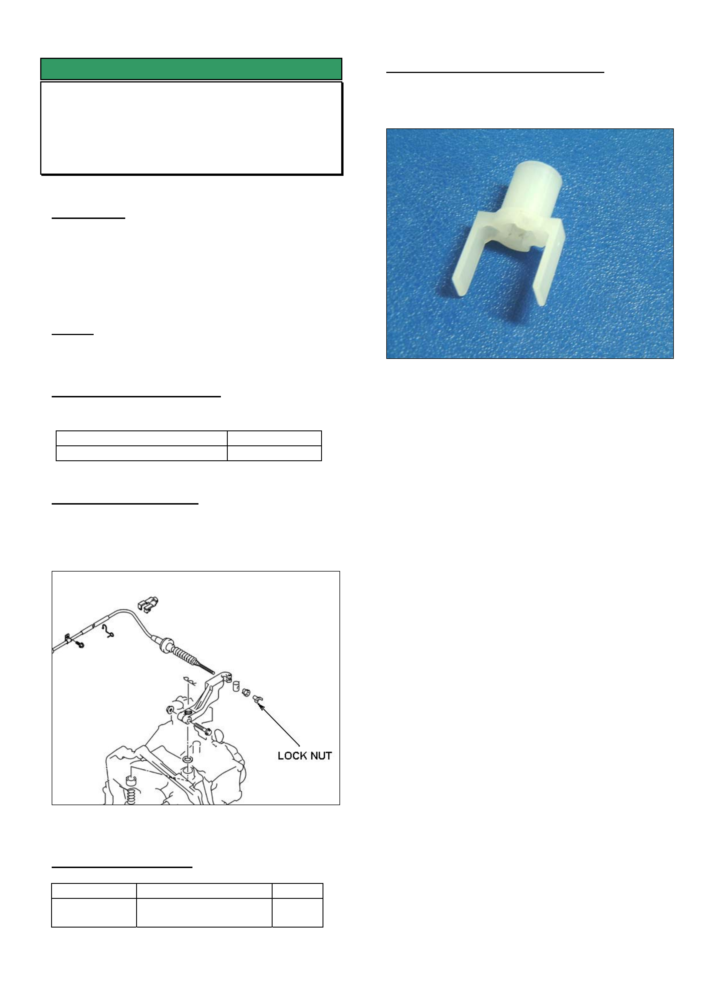
1. Add locknut 92125625 to end of clutch cable.
Refer Figure 1.
2. Adjust clutch cable as per procedure in LCV SIP
Figure 1
PARTS INFORMATION
Part No.: Description: Qty:
92125625 Nut Lock Cable
adjusting
1
WARRANTY CLAIM INFORMATION
Use Labour Times information in Warranty
Information section of current PV SIP CD
Figure 2. Closeup of Locknut
HOLDEN SERVICE TECHLINE __________________________________________________________________APRIL, 2004
14
SERVICE INFORMATION
Laden Vehicle Trim Height Specification
RA Rodeo
(GROUP 4) REVISED TL0624A-0403
This techline supersedes the previous one (TL0624-
0401) published in Issue 1, 2004.
IMPORTANT: All copies of the previous techline
should be destroyed or marked as being superseded.
----------------------------------------------------------------------
The following information is provided to assist Dealers
when a customer complains of excessive spring
deflection when the vehicle is loaded.
SERVICE RECOMMENDATION
Use the following procedure to check spring deflection
against factory specification.
Step 1. Have the customer present the vehicle
to the retailership in the complaint condition (i.e.
loaded).
Check all spring shackles/bushes for condition and
rectify as required.
Step 2. The vehicle must then be loaded to
achieve the Gross Vehicle Weight (GVW) Axle
Loadings as shown in following table. This will need
to be done on a vehicle weighing platform. It is
recommended to use sand bags to achieve the GVW
axle loadings.
Gross Vehicle Weight - Axle Loadings (kgs)
4x2 vehicle 4x4 vehicle
Front axle 1120 kg 1220 kg
Rear axle 1680 kg 1680 kg
Step 2 After achieving the above front and
rear axle loads, the dimensions as shown in the
following figures 1, 2, 3, & 4 can now be measured.
Step 3. Compare measurements taken in step
2 to those in Figure 5. Remember to take into
account the tolerances (+/-) on the specifications.
Also, the bump stop clearances are given for
reference only. If the measured vehicle trim heights
are below the specifications given, the spring
deflection is greater than production specification.
Figure 1. Front Trim height “Z” = A - B
Figure 2. Front bump stop clearance T (For
reference only)
Figure 3. Rear suspension height “H”
HOLDEN SERVICE TECHLINE __________________________________________________________________APRIL, 2004
15
Figure 4. Rear bump stop clearance “C”
(for reference only)
4 x 2 4 x 4
4JH1 & 6VE1 C24SE 4JH1 & 6VE1
RA Rodeo
Vehicle Trim Height
Specifications @ GVW Standard
Rear springs
(5 leaves)
HD
Rear springs
(7 leaves)
Standard
Rear springs
(5 leaves)
HD
Rear springs
(7 leaves)
Standard
Rear springs
(5 leaves)
HD
Rear springs
(7 leaves)
Trim Height
Z 83.2 83.2 60.8 60.8 108.0 108.0
Bump stop
clearance
T (Ref only)
17.8 17.8 9.4 9.4 17.0 17.0
Front
Tolerance mm +/- 7
Suspension
height
H
75.2 88.3 75.2 88.3 91.9 104.0
Bump stop
clearance
C (Ref only)
9.4 22.5 9.4 22.5 9.5 21.6
GVW
Rear
Tolerance
(mm) +/- 6
Figure 5. RA Rodeo -Trim Height Specifications at Gross Vehicle Weight. (All dimensions are in mm).
NOTES.
• Front Trim Height “Z” and Rear Suspension height “H” are the critical dimensions to be looked at when
assessing the condition of the vehicle springs.
• Front ( “T” ) & Rear ( “C” ) bump stop clearance should be used as reference data only.
• All measurements should be taken with the vehicle on a flat surface
• All measurements should be taken at the specified tyre pressure
• Vehicle weight distribution must comply with the front and rear axle weights for GVW loading as per
following table.
•
Gross Vehicle Weight - Axle Loadings (kgs)
4x2 vehicle 4x4 vehicle
Front axle 1120 kg 1220 kg
Rear axle 1680 kg 1680 kg

HOLDEN SERVICE TECHLINE __________________________________________________________________ MAY, 2004
5
SERVICE FIX
Intermittent No Crank or No Start
- Immobiliser Related
RA Rodeo
(GROUP 12) TL0541A-0404
This Techline supersedes and cancels the previous
one (TL0541-0311) published in Issue 11 Nov, 2003.
PROBLEM DESCRIPTION
Customers may advise that intermittently their vehicle
will not crank or will crank and not start.
This problem has often been isolated to an
intolerance within the immobiliser control unit
software, which can be highlighted by electrical noise
generated from the accessory socket relay and any
accessories powered from the accessory socket
circuit.
PRODUCTION RECTIFICATION
Revised immobiliser software was introduced into
vehicle production in May 2004. The specific
breakpoint will be published in the breakpoint
summary when available.
SERVICE RECTIFICATION
A revised immobiliser is now available from HSPO
and should be fitted to any vehicle when the customer
advises of this problem.
Install the revised immobiliser as per the LCV SIP
procedures:
• RA Rodeo/Section 11 – Immobiliser
System/Tech 2 Scan Tool/Reset Immobiliser.
• RA Rodeo/Section 11 – Immobiliser
System/Tech 2 Scan Tool/Programming ICU.
• RA Rodeo/Section 11 – Immobiliser
System/Tech 2 Scan Tool/Transponder
Program.
Please note the following;
Ensure that the vehicle is presented with both the
original ignition keys so they can be programmed to
the new immobiliser.
Use the original vehicle security code when
programming the new immobiliser.
WARRANTY CLAIM INFORMATION
Description Immobiliser Replacement
Labour Op. No. R123000
Time 0.4 hr
Failure Code R0084
PARTS INFORMATION
Part No.: Description: Qty:
8973773240 Diesel Immobiliser 1
8973773230 Petrol Immobiliser 1
HOLDEN SERVICE TECHLINE __________________________________________________________________ MAY, 2004
6
Central locking module
SERVICE FIX
Central Locking System Poor Remote
Range
RA Rodeo
(GROUP 12) TL0669-0404
CONDITION
Some customers may advise that intermittently their
central locking remotes do not operate.
CAUSE
High levels of environmental electrical interference
caused by mobile telephone transmitter towers or
high voltage power lines may interfere with the
operation of the central locking remote.
CORRECTION – Production
The central locking module has been repositioned
and revised central locking remotes with improved
range have been fitted in production from the
following breakpoint.
ISOVIN: Built Date:
MPATFS77J4H533835 01/04/04
CORRECTION – Service
When presented with a vehicle where the customer
advises the central locking remotes intermittently do
not operate, the following steps should be performed.
Step 1. Ensure the vehicle has been presented
with both original remotes and the
vehicle security code.
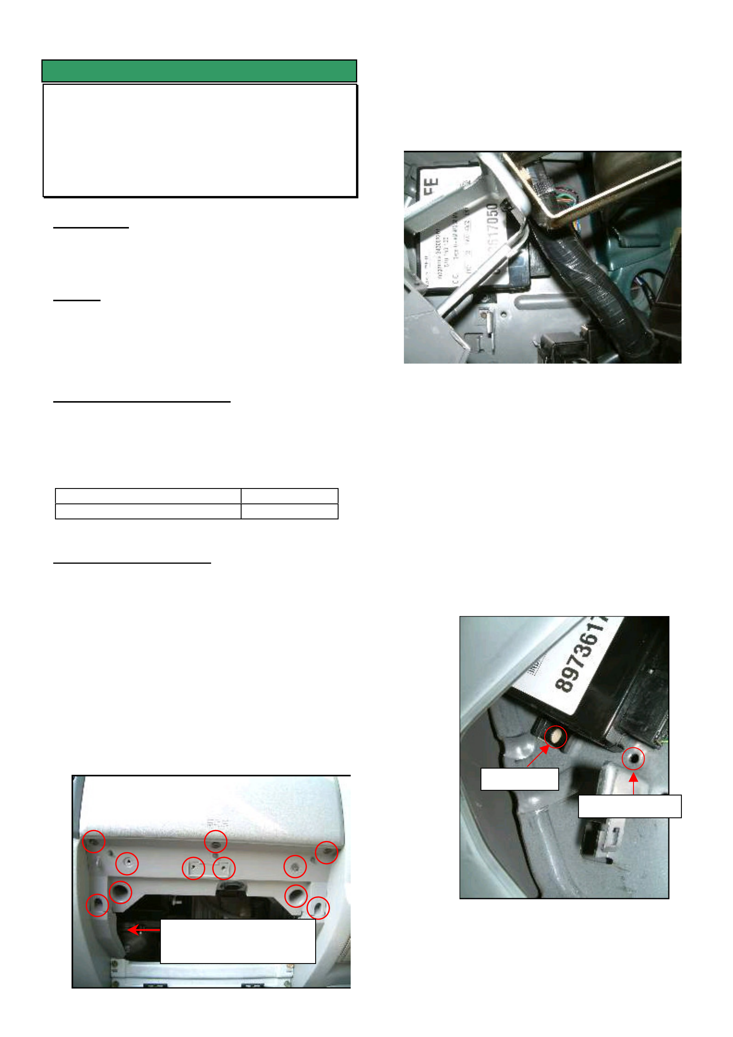
Step 2. Remove the glove box (two screws on the
lower edge) and the glove box cover (9
screws and two bolts as per the picture
below).
Step 3. Remove the central locking module located
to the left hand side of the glove box
opening (as per the photo below) by
removing the two attaching screws.
Step 4. Clean any grease or oil from the back of
the central locking module and the panel it
mounts to (to allow the double sided tape
to stick).
Step 5. Attach one side of the double-sided tape
(92148253) to the lower attaching lug of the
central locking module, refit the module in
position with the top attaching screw only
(do not tighten yet).
Step 6. Rotate the module clockwise approximately
300 (or as far as possible) around the top
mounting screw (as per the picture below).
Step 7. Tighten the top mounting screw and
confirm the module is securely located.
Ori
g
inal
New
HOLDEN SERVICE TECHLINE __________________________________________________________________ MAY, 2004
7
Step 8. Using Tech 2 program the two new remote
keys as per LCV SIP.
RA Rodeo / System Electrical / Section 8A Electrical –
Body and Chassis / Keyless Entry
Step 9. Ensure that both remotes operate after
programming.
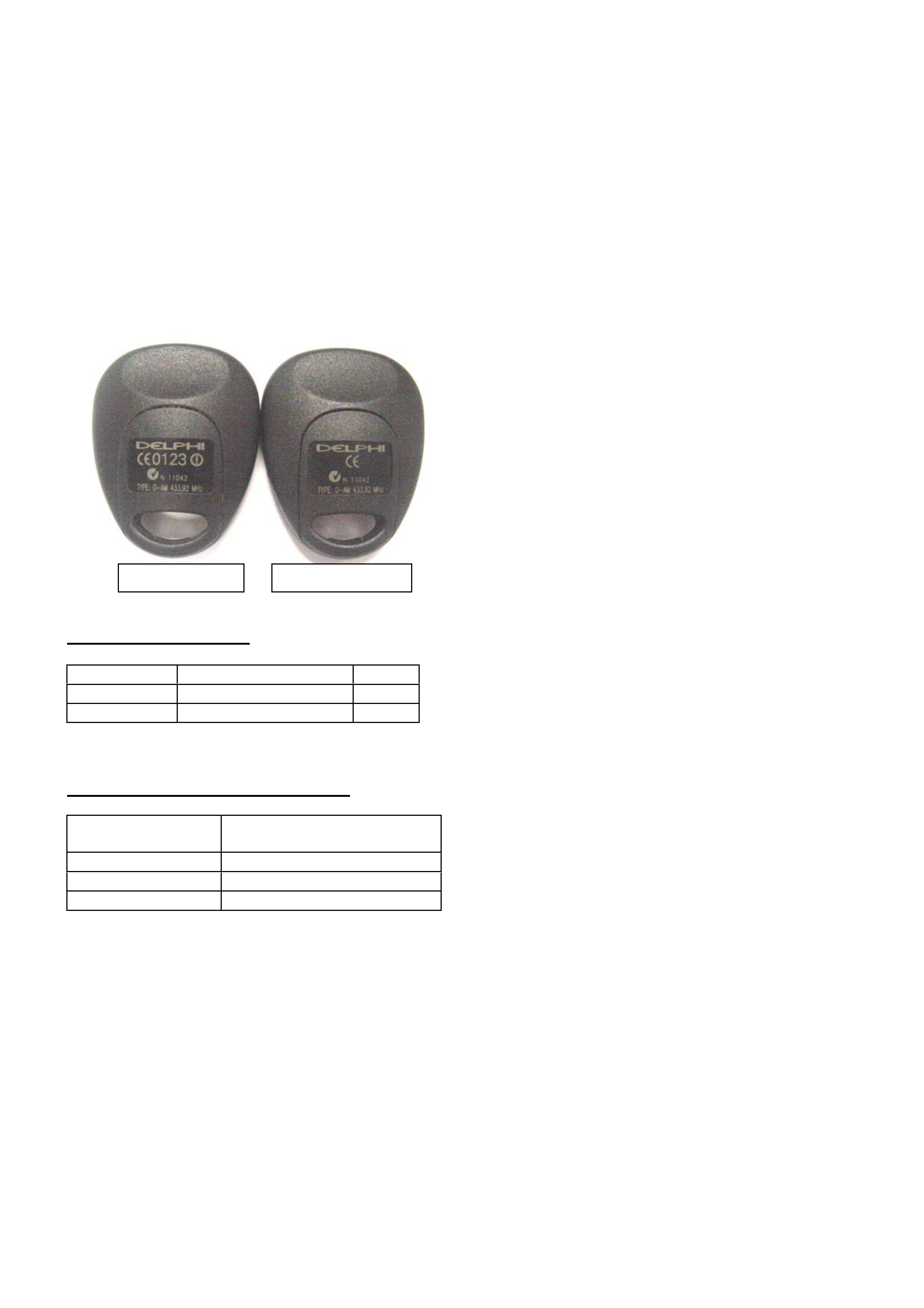
The new remotes can be identified by a change to the
numbering on the back as per the photo below.
PARTS INFORMATION
Part No.: Description: Qty:
8973784420 Remote Transmitter 2
92148253 Double sided tape 1
WARRANTY CLAIM INFORMATION
Description Central Locking Remote
Improved Range
Labour Op. No. N000463
Time 0.5 hr
Failure Code N0057
Old t
yp
e remote
N
ew t
yp
e remote

HOLDEN SERVICE TECHLINE __________________________________________________________________ MAY, 2004
8
INFORMATION
Immobiliser VIN Number Programming
RA Rodeo
(Group 12) TL0693-0404
PROBLEM DESCRIPTION
When programming the VIN number into the
immobiliser on an RA Rodeo, only 8 digits can be
programmed
PRODUCTION RECTIFICATION
When installing a new immobiliser into an RA Rodeo
you are requested via Tech 2 to program the VIN
Number into the new immobiliser. Tech 2 only allows
you to program 8 of the numbers. The 8 numbers
required are the last 8. Even if the old immobiliser
had something other than the last 8 you are still
required to program the last 8 .
E.g. Full VIN number is: MPATFS77J3T100177
Number to be programmed is: 3T100177
To program letters use the up/down arrow keys and
scroll through the alphabet, numbers can be
programmed in the same way or by using the
numbers on the keypad.
Please note the following;
Ensure that the vehicle is presented with both the
original ignition keys so they can be programmed to
the new immobiliser.
Use the original vehicle security code when
programming the new immobiliser.
HOLDEN SERVICE TECHLINE __________________________________________________________________ MAY, 2004
10
INFORMATION
TIS 2000 error message when accessing Service Information or Security Access
TIS 2000
(GROUP OB) TL0690-0404
This techline is to be used in conjunction with Technicians guild article number 8 of 2003
PROBLEM DESCRIPTION
TIS 2000 displays error codes when user attempts to access some functions. Prior to seeking help from
TAS, it is recommended you perform the following checks.
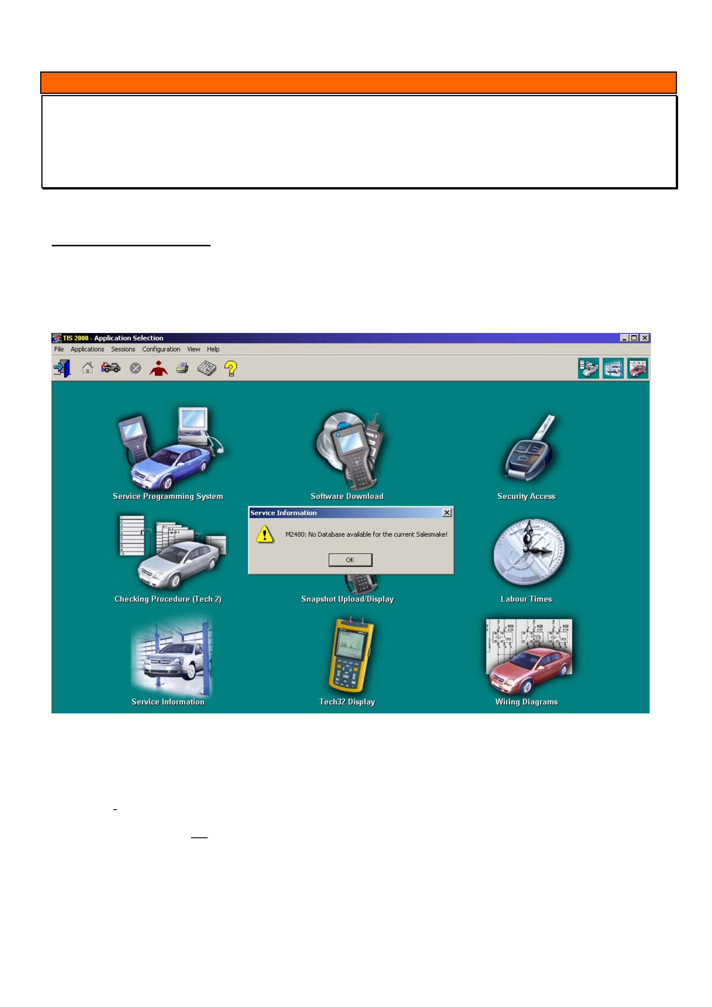
When accessing Service Information the following screen may appear.
To overcome this problem, click the “ok” button in the message box. Click on the word “configuration” at the top of
the screen, select “options”. Starting from the left tab make sure the following selections are made.
Language: English (united states)
Country: Australia or New Zealand as applicable
Salesmake: Opel (unless doing Isuzu product then select Isuzu, do not select Holden for any product)
Dealership: Holden
WWW: Do not tick the enable java box
Click “ok”
After the settings have changed, a message box will appear advising that the salesmake settings have changed and
TIS must be restarted, click YES to this. Another message about closing open sessions will appear. If there are no
other open sessions click “YES”. Restart TIS and retry service information. If you continue to have problems with
service information a TAS nominated contact should contact TAS.
HOLDEN SERVICE TECHLINE __________________________________________________________________ MAY, 2004
11
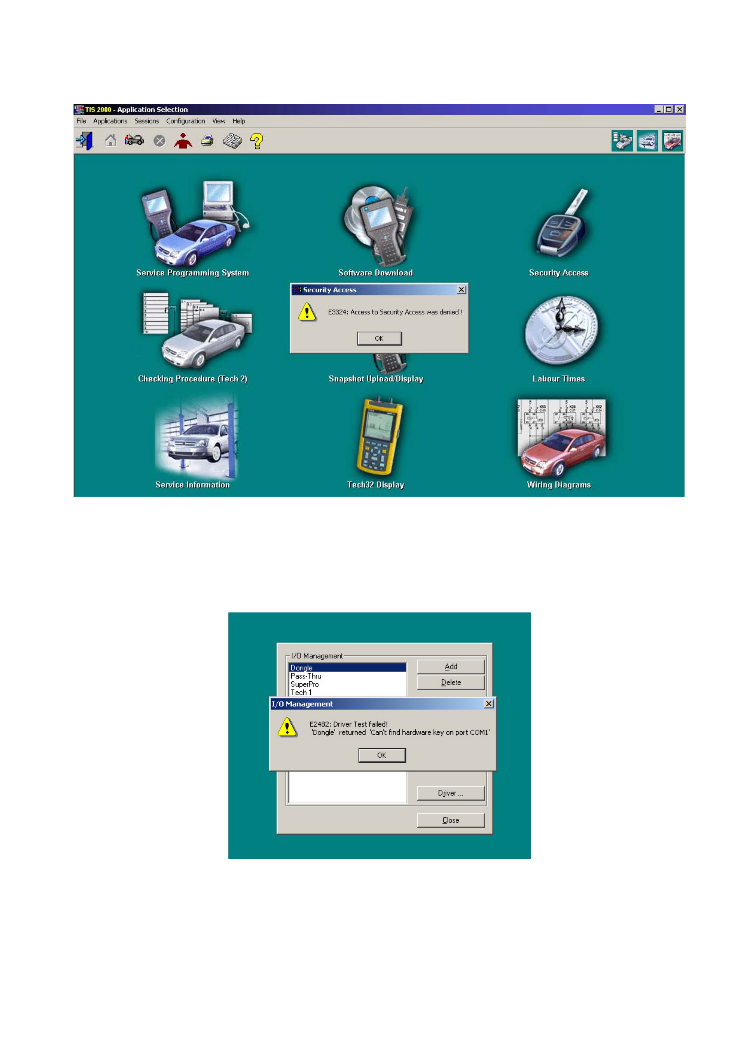
When accessing Security Access the following message may appear.
(Make sure your hardware key is installed prior to attempting to obtain Security Access).
.
Click the “ok” button in the message box and then click on the word “configuration” at the top of the screen.
Select “I/O management” and make sure “Dongle” is highlighted (unless you have the new super pro USB hardware
key in which case “super pro” will need to be highlighted). Press the “test” button on the right hand side. The
following message may appear.
Click “ok” in the message box and then press the “properties” button on the right hand side. A box displaying the
current com port that is selected will appear. Click on the black arrow on the right of the message box; this will
display the other com ports available. Select a different com port than the one displayed (not LPT1) and click ok.
Press the test button again. If more than 2 com ports available then this may have to be done again on all com ports
until it passes. When message appears saying “Driver test successful” click “ok” and close I/O management box.
Retry Security access.
If problems still occur a TAS nominated contact should contact TAS.

HOLDEN SERVICE TECHLINE __________________________________________________________________ MAY, 2004
12
INFORMATION
TIS 2000 Update And Uninstall Procedure
(GROUP 0B) TL0691-0404
TAS receive many calls where a TIS 2000 Update or
a new TIS 2000 Installation has failed. This techline
is to clarify the following procedures:
• Update TIS 2000
• Uninstall TIS 2000
• TIS 2000 Configuration Options
If your Dealership has a PC specialist, it would be an
advantage to utilise his/her expertise.
Update TIS 2000
To update TIS 2000 proceed as follows:
• Place TIS CD1 in your disc drive, wait a few
seconds and then click on the icon, which
opens TIS 2000. This will then see the disc as
an update and continue to upload. On
completion of the first, it will request that you
load the second disc. When the second disc
is inserted, click OK in the dialog box to begin
the upload.
• Both LCV TIS and Wiring Diagrams CD’s
should be treated as an Update.
Uninstall TIS 2000
To uninstall TIS 2000 proceed as follows:
• Remove any cd’s from all drives.
• Shut down and Restart your computer (PC).
• Click on the Start button (lwr left of screen).
• Move up to programs then across to TIS 2000
and again across to TIS 2000 Uninstall.
Select Uninstall from this menu.
• When the Uninstall is fully complete it should
advise if it was successful. If not, you will
need to run through the following procedures.
• Click on the Start button again and choose
Search or Find, moving over to Files or
Folders.
• Type cosids in the search field, and then
choose local hardrives in the look-in field.
Now select Search/Find now. This will
generate a search for the TIS 2000 main files.
(If any files are found it will be displayed in the
large box to the right, if not continue to next
step)
• Delete all files that have been found, by
selecting with your mouse and hitting the
delete button on your keyboard.
• Now click on the Start button again and scroll
up to Settings, then move across to Control
Panel. In this menu, double click on
Add/Remove Programs and look for the
following items:
JAVA 2 RUNTIME ENVIRONMENT STD EDITION
and
JAVA SERVLET DEVELOPMENT KIT.
• If they are available, select one at a time then
hit the Change/Remove button for each.
Close this window.
• It is now very important to restart your
computer.
TIS 2000 CONFIGURATION OPTIONS
When attempting a complete TIS 2000 install, place
CD1 in the drive and this should now begin the
installation. It will request the second CD when
required.
Follow all prompts until the installation is complete.
NOTE: it is very important that you select the following
configuration when prompted:
• Language – English
• Country – Australia/New Zealand (whichever
is applicable)
• Salesmake – OPEL
• Dealership – HOLDEN
• WWW – not checked (ticked)
You will also need to select which COM port you
would like your TECH 2 and Hardware Key to
communicate with. You must ensure these are both
the same. E.g.; COM1 or COM2.
HOLDEN SERVICE TECHLINE __________________________________________________________________ MAY, 2004
16
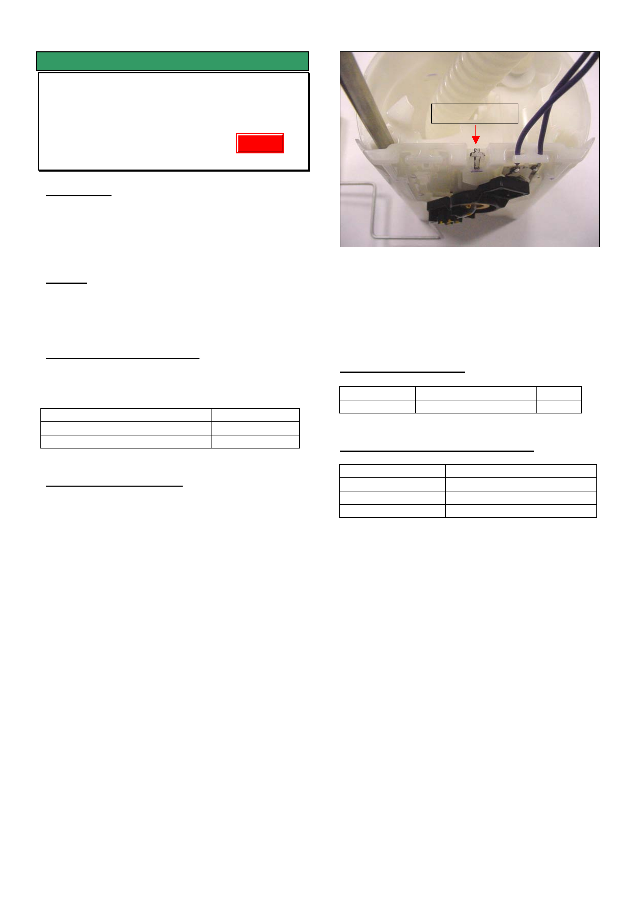
SERVICE FIX
Fuel Gauge Reads Empty With 25 Litres
Left In The Tank
RA Diesel
(GROUP 12) TL0576-0404
CONDITION
Customers may advise that when the fuel gauge
reads empty they can still have approximately 25
litres left in the tank.
CAUSE
The fuel sender card calibration results in “Empty”
being displayed too early.
CORRECTION – Production
A revised fuel sender card has been fitted in
production from the following breakpoint.
ISOVIN: Built Date:
MPATFR77H4H514631 (2 X 4) 10/11/03
MPATFS77H4H515657 (4 X 4) 19/11/03
CORRECTION – Service
The revised fuel sender card assembly is available
from HSPO and should be fitted to the original
Modular Reservoir Assembly (MRA).
Step 1. Remove the MRA as per the LCV SIP
instructions.
RA Rodeo / Engine 4JH1 / Section 6C-Engine Fuel / Fuel
Gauge Unit
Step 2. Once the MRA is removed disconnect the
sender card wiring under the top cover.
Step 3. The fuel sender card assembly can now be
removed from the MRA body by
disengaging the double-sided clip at the
top. (refer picture)
NOTE: Care should be taken not to damage the MRA
when removing the sender card assembly.
Step 4. Refit the new sender card assembly and
reconnect the wiring.
Step 5. Refit the fuel tank as per the LCV SIP
procedure and check the operation of the
fuel gauge.
PARTS INFORMATION
Part No.: Description: Qty:
8979431780 Fuel Sender Card 1
WARRANTY CLAIM INFORMATION
Description R& R Fuel Sender Card
Labour Op. No. L000239
Time 1.1 hr
Failure Code NOW N0057
Double sided
Update
HOLDEN SERVICE TECHLINE __________________________________________________________________ MAY, 2004
20
SERVICE FIX
Air Outlet Vents Difficult To Adjust
RA Rodeo
(GROUP 2) TL0668-0404
CONDITION
Customer complains the interior air vent(s) are difficult
to adjust.
Closer inspection reveals the vent is fractured.
CAUSE
Incorrect chemical composition of vent material which
results in embrittlement of the material with age.
CORRECTION – Production
Revised material vents have been fitted to vehicles
from:
ISOVIN: Built Date:
MPATFS77H4H501806 01/07/2003
CORRECTION – Service
On any vehicle built prior to the above Breakpoint
which has a fractured air vent grille, it is
recommended to replace all four vents in the dash
pad with latest revised parts.
PARTS INFORMATION
To obtain a kit of revised vents (kit contains 1 x LH
outer, 1 x RH outer and 2 centre) fax an order form to
Salmat on 9358 2999. The order form is to be a
copy of this page.
NOTE: When the sets of revised vents can no longer
be obtained from Salmat (supplies are limited) the
following parts will need to be obtained from HSPO.
Refer to the latest Partfinder for part numbers of these
components.
Part No.: Description: Qty
refer latest
Partfinder
Cluster – Instrument centre
(contains 2 centre vents)
1
refer latest
Partfinder
Grille – side, air outlet LH 1
refer latest
Partfinder
Grille – side, air outlet RH 1
WARRANTY CLAIM INFORMATION
Description Replace all 4 air outlet
vents in dash.
Labour Op. No. D000348
Time 0.6 hr
Failure Code D0005 Cracked
REQUEST for - RA Air Vent Car Set
Fax this form to Salmat on 03 9358 2999
Date of request :
Dealer Name :
Dealer Code :
Dealer Address for parts
delivery :
17 digit ISOVIN of vehicle
parts are required for :
Name of person
requesting parts :
Contact Numbers : Phone: Facsimile:
For Salmat Use Only:
Date Parts Despatched