
SECTION 1 - GENERAL INFORMATION
IMPORTANT:
Before performing any Service Operation or other procedure described in this Section, refer to
Section 00 CAUTIONS AND NOTES and Section 2 PRECAUTIONS in this Supplement for correct
workshop practices with regard to safety and/or property damage.
CAUTION:
The Structure of the VY & V2 Series II Ser ies body shell has be en developed using complex design and
development techniques. In addition to meeting all required standards, the vehicle body is also a
critical part of the overall safety systems. It is therefore imperative the repair procedures described
here are adhered to during all vehicle body repairs.
CONTENTS
1. INTRODUCTION
2. GENERAL INDEX
3. REPAIR PROCEDURES
3.1 FRAME STRAIGHTENING
3.2 ROUGH CUTTING
3.3 CUTTING MIG WELDS
3.4 SPOT WELD CUTTING
3.5 LAP JOINTING
3.6 REPAIRING THE BODY ALIGNMENT
4. WELD REPAIR METHODS
4.1 GENERAL INFORMATION
4.2 SPOT WELDING
SPOT WELDER
PANEL CONDITION
NUMBER OF WELDS
WELD TESTING
4.3 PLUG WELDING
4.4 FUSION WELDING
BUTT WELDED JOINTS
LAP WELDED JOINTS
BRONZE WELDS
WARP PREVENTION ON LONG WELDS
4.5 WELDING LEGEND

1. INTRODUCTI O N
The MY 2003 VY & V2 Series vehicles are designed to meet or exceed all frontal, offset frontal and side impact
standards. It is imperative therefore, that any repairs to a MY 2003 VY & V2 Series vehicle does not compromise:
• the vehicle’s compliance with relevant statutory regulations,
• the performance of the body structure, or
• the vehicle’s safety systems – including the occupant protection system.
Any repairs are to be performed in accordance with this Supplement, which provides replacement procedures for
MY 2003 VY & V2 Series body panels and structural members.
Hang-on panels suc h as the engine hood, deck lid and f ront f ender s are not covered and refer ence should be made
to the appropriate Section in the MY 2003 VY & V2 Series Service Information.
Replacement procedures for the door assemblies and outer panels, along with instructions for disassembling and
removing the glued-in dash panel assembly, are the only instructions in this Supplement that do not involve
components welded to the vehicle structure.
This Supplement has been prepared for trades persons suitably qualified in the Automotive Body Repair Industry.
As such, welding technique, panel beating or surface finishing instruction, etc. is not included. The purpose of this
Supplement is to ass ist the repairer to use his/her expertis e in m ak ing the correct judgem ents to restore the vehicle
to original condition and specification.
Prior to beginning repair work on a vehicle, the repairer should becom e fam iliar with Section 1 through Section 3 in
this Supplem ent, Section 00 in the MY 2003 VY & V2 Series II Service Inf orm ation and any appropriate regulations
covering repairs, welding and joining motor vehicles and accepted industry practices.
As collision damage differs in each case, this Supplement can only be a guide for the repairer. The best repair
procedure for each vehicle will need to be determined according to the judgements of a qualified trade’s person.
The Supplement describes the replacement procedures of service parts available for MY 2003 VY & V2 Series
vehicles. If several adjoining parts are replaced at the one time, modify the replacement procedures accordingly.
The nam ing of body sections and parts in this Supplement fo llows Global Part Descr iption System (GPDS) nam ing
conventions.
The information contained in this Supplement is correct at the time it was approved for printing. However, as the
motor vehicle industry is constantly updating and improving vehicle construction techniques, the repairer must use
his/her acquired skill in determining the appropriate procedure for replacing panels.
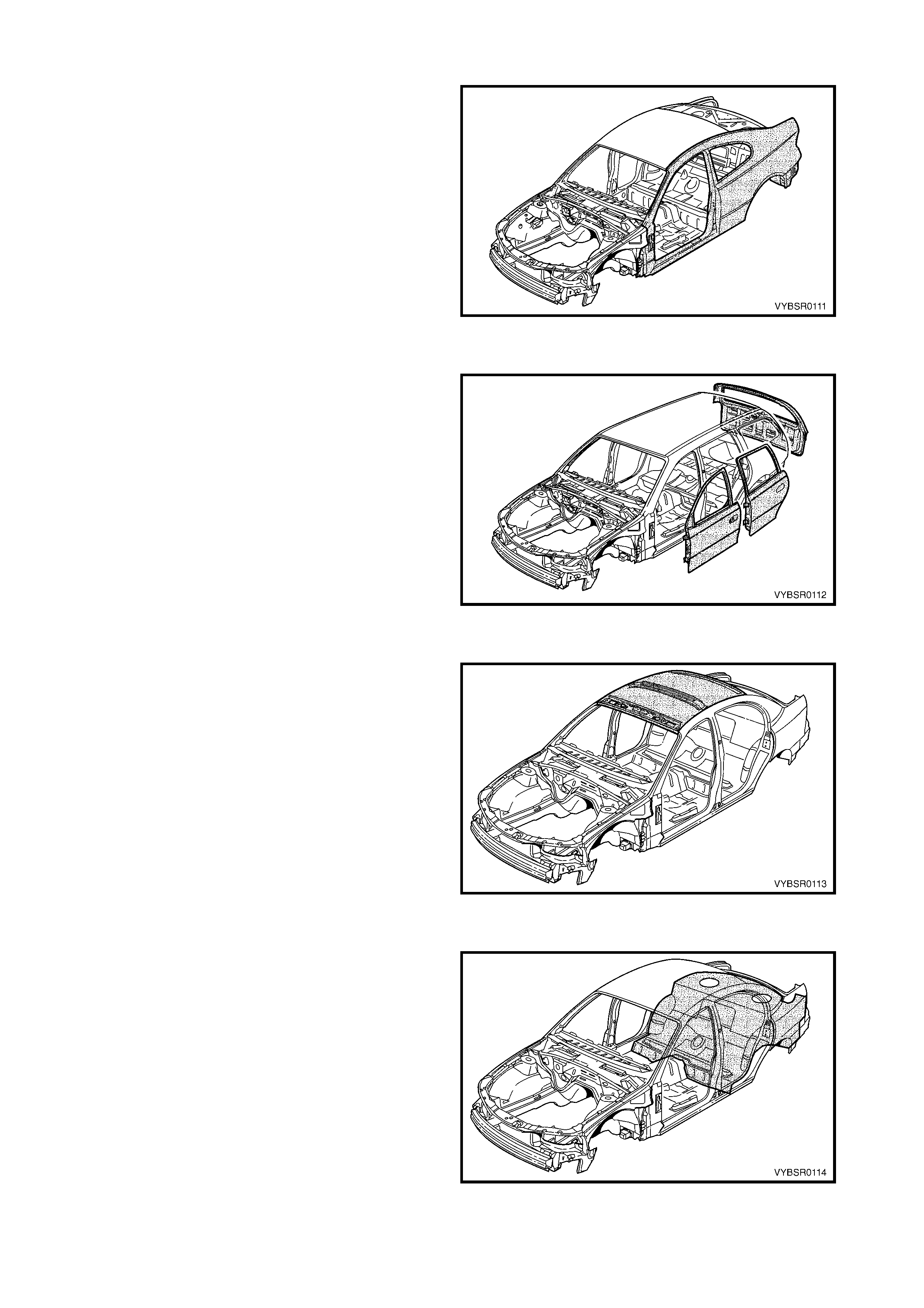
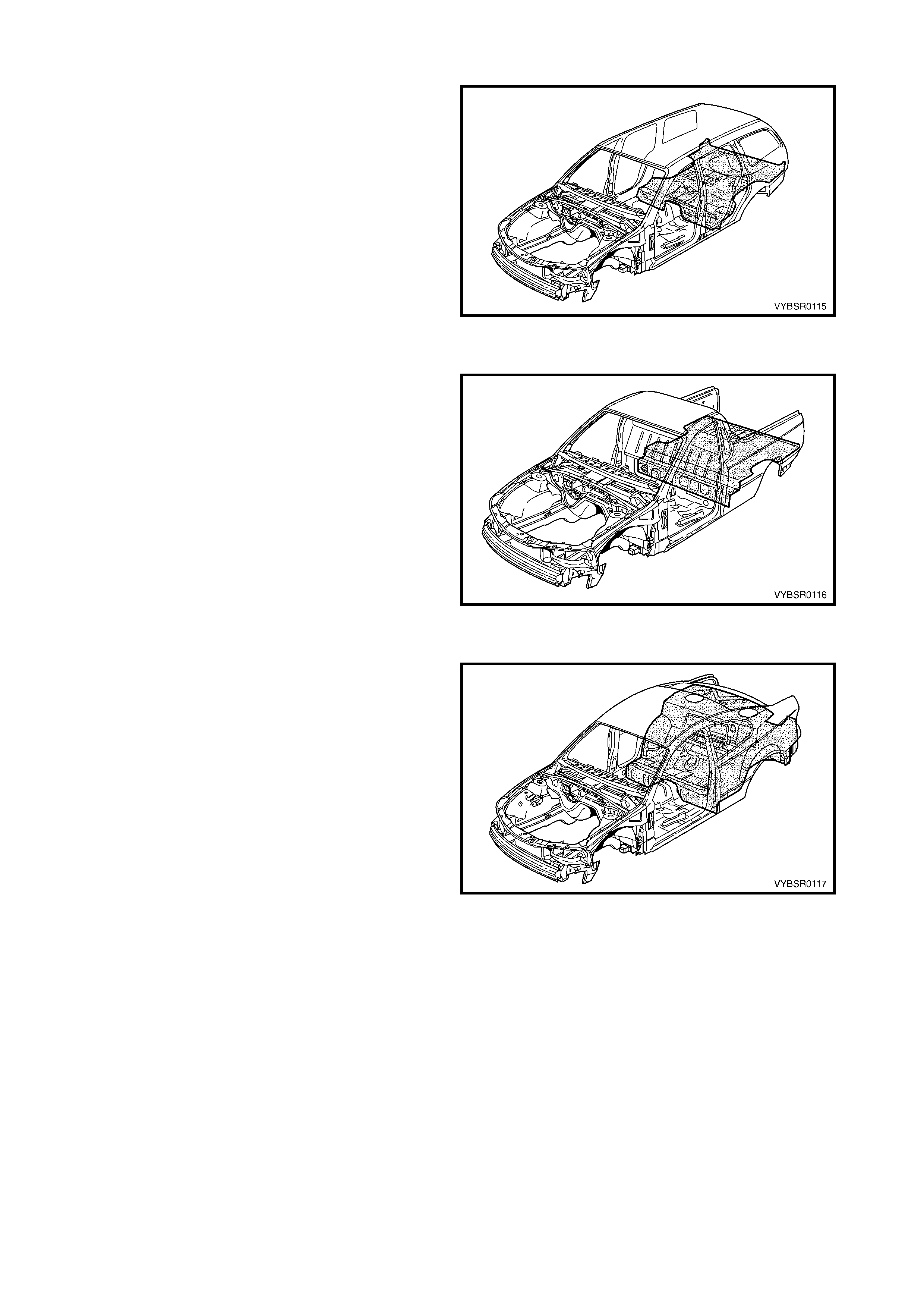
Figure 1-1 shows the MY 2003 VY & V2 Series II body structure as covered by this Supplement.
NOTE: The Vehicle Data information previously included in this Section is now located in Section OA GENERAL
INFORMATION of the MY 2003 VY & V2 Series Service Information.
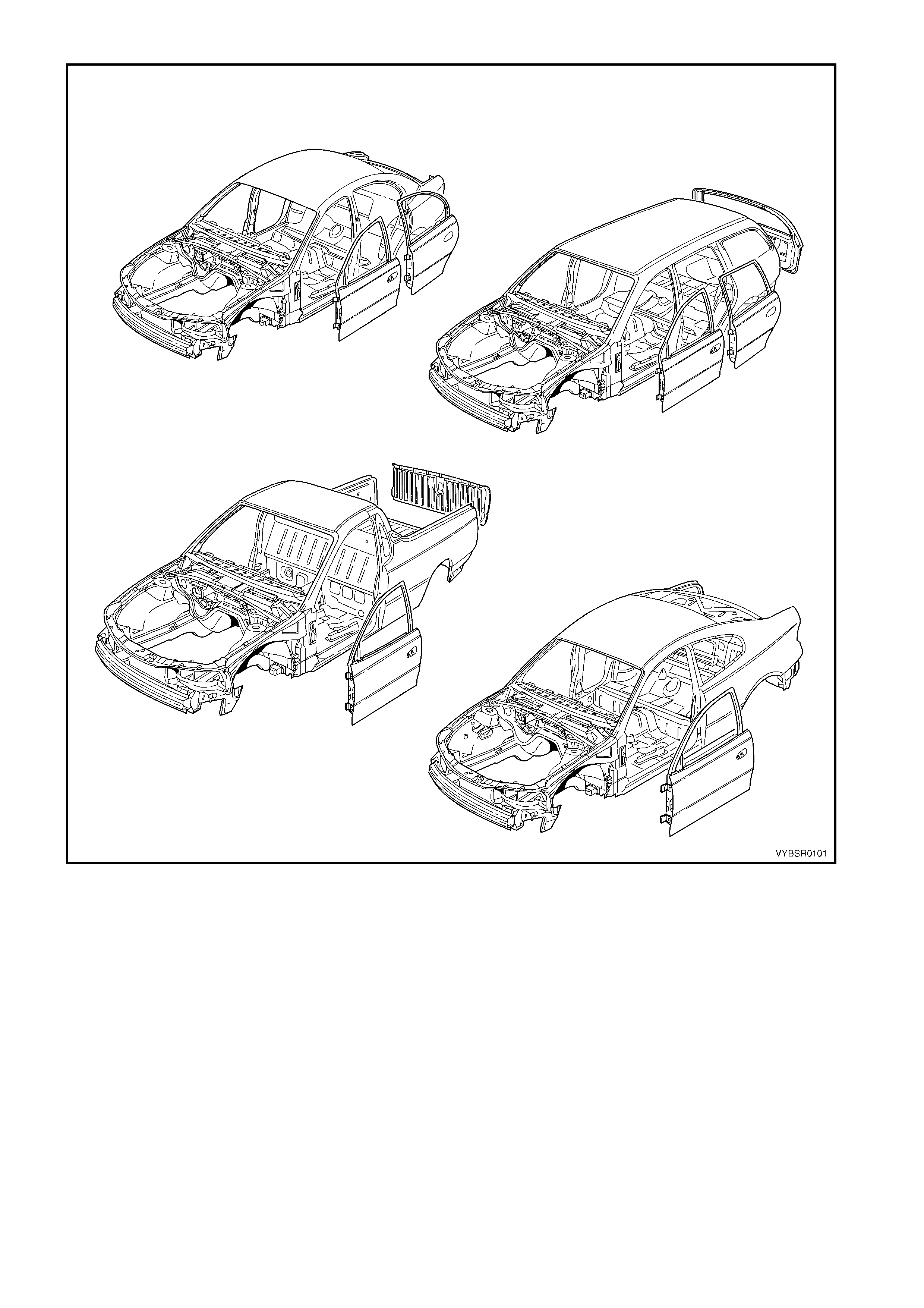
Figure 1-1
2. GENERAL INDEX
SECTION 1 GENERAL INFORMATION
Description
1. Introduction
2. General Index
3. Repair Procedures
4. Weld Repair Methods
SECTION 2 PRECAUTIONS
Description
1. General Description
2. Personal Safety Precautions
3. General Precautions
4. Occupant Protection System Precautions
5. Electrical Precautions
6. Jacking Precautions
7. Towing Precautions
8. Plastic Components
9. Special Steel Precautions
10. Cavity Foam
11. LPG Precautions
SECTION 3 BODY CONSTRUCTION
Description
1. General Description
2. Bumper Impact Bar Assemblies
3. Special Tools
SECTION 3A BODY CONSTRUCTION – SEDAN
Description
1. General Description
2. Body Structure Panels
3. Body Dimensions
4. Body Margins
5. Body Sealing, Adhesives and Deadeners
6. Cavity Wax
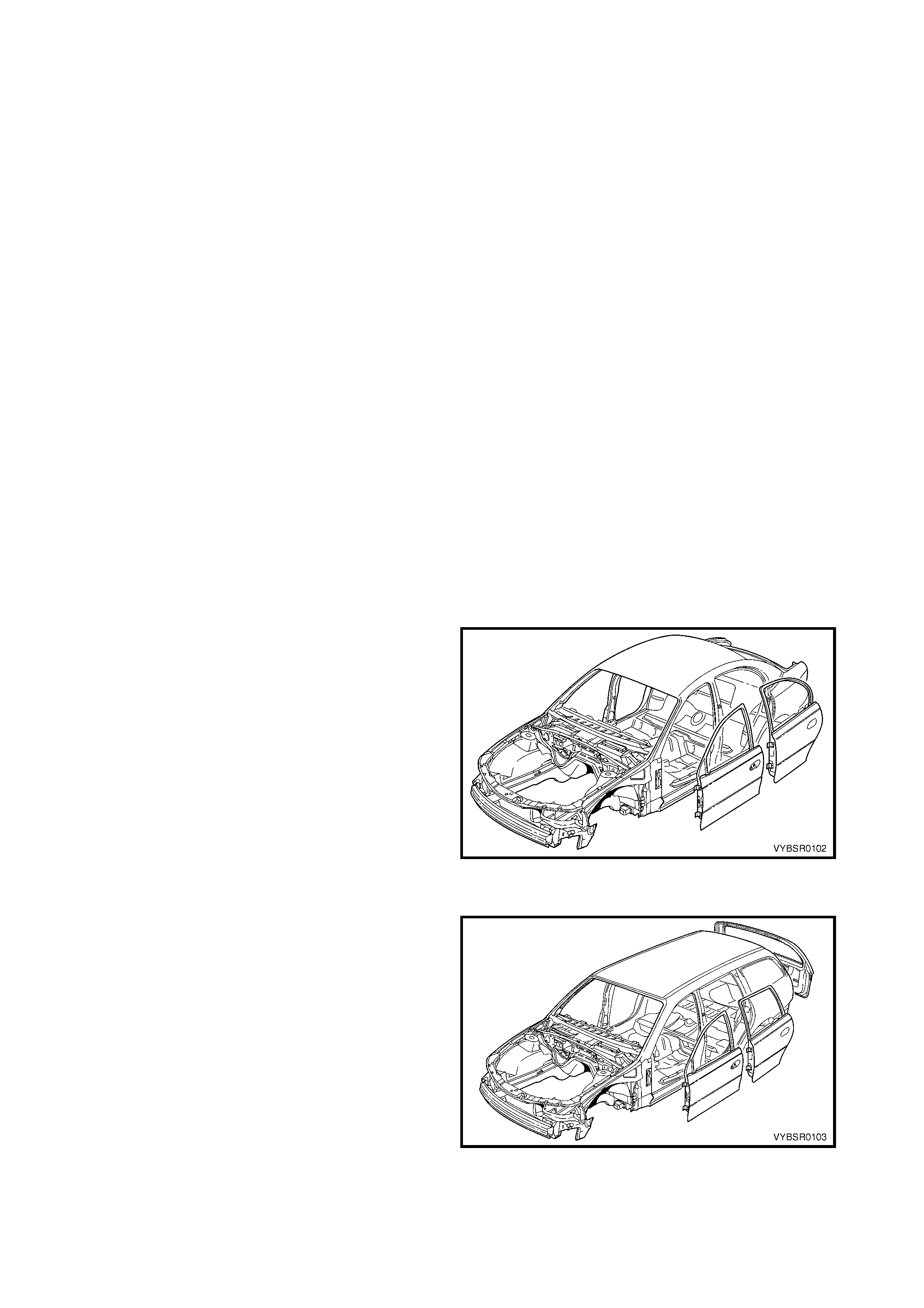
Figure 1-2
SECTION 3B BODY CONSTRUCTION – WAGON
Description
1. General Description
2. Body Structure Panels
3. Body Dimensions
4. Body Margins
5. Body Sealing, Adhesives and Deadeners
6. Cavity Wax
7 Roof Joint Moulding
Figure 1-3
SECTION 3C BODY CONSTRUCTION – UTILITY
Description
1. General Description
2. Body Structure Panels
3. Body Dimensions
4. Body Margins
5. Body Sealing, Adhesives and Deadeners
6. Cavity Wax
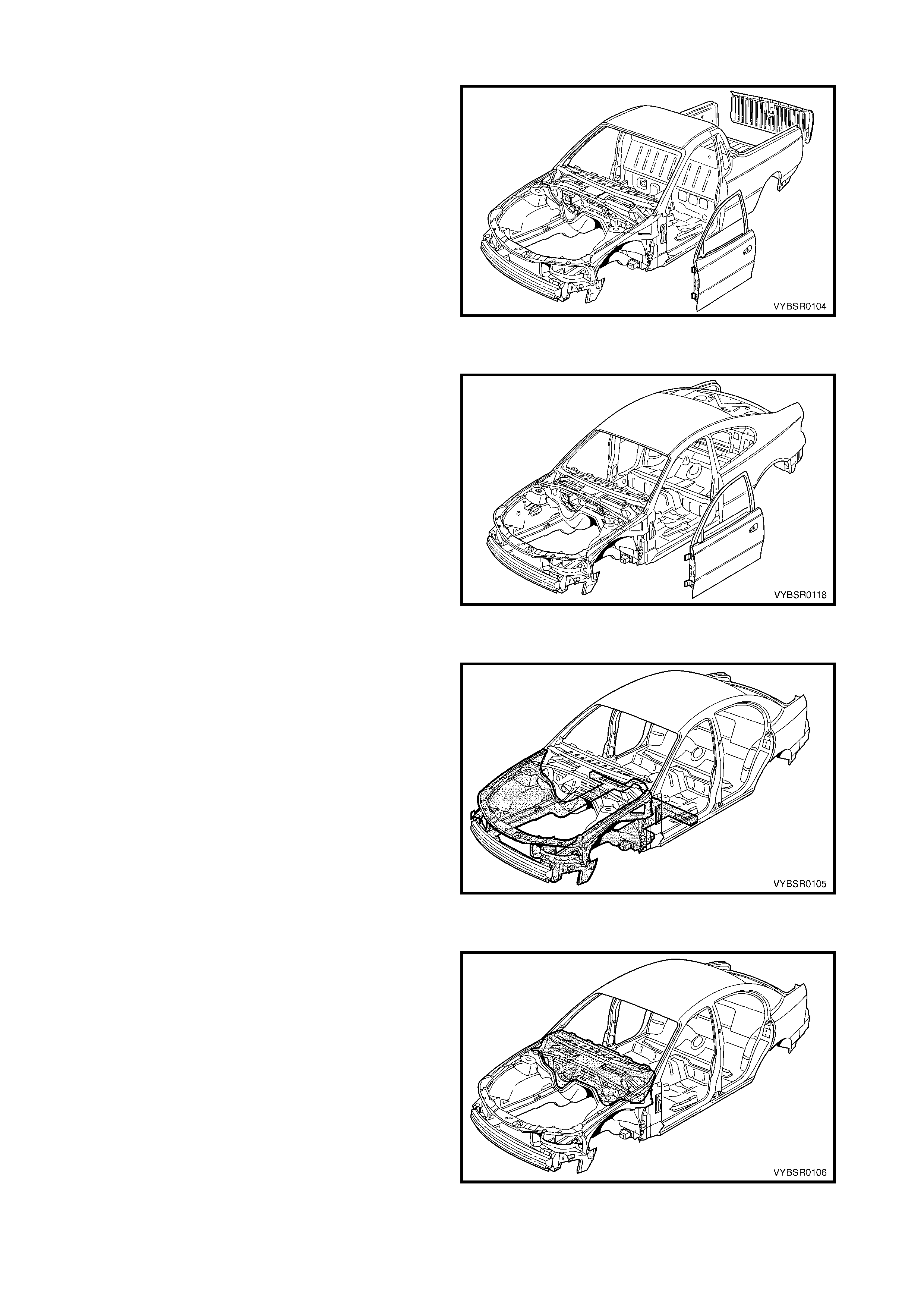
Figure 1-4
SECTION 3D BODY CONSTRUCTION – COUPE
Description
1. General Description
2. Body Structure Panels
3. Body Dimensions
4. Body Margins
5. Body Sealing, Adhesives and Deadeners
6. Cavity Wax
7 Rear Seat Back Panel Centre Extension
Figure 1-5
SECTION 4 FRONT END
Description
1. General Description
2. Service Operations
Figure 1-6
SECTION 5 COCKPIT MODULE
Description
1. General Description
Figure 1-7
SECTION 6 CABIN FLOOR & UTILITY SEATBACK ASSEMBLY
Description
1. General Description
2. Service Operations – Cabin Floor
3. Service Operations – Utility Seat Back
Assembly
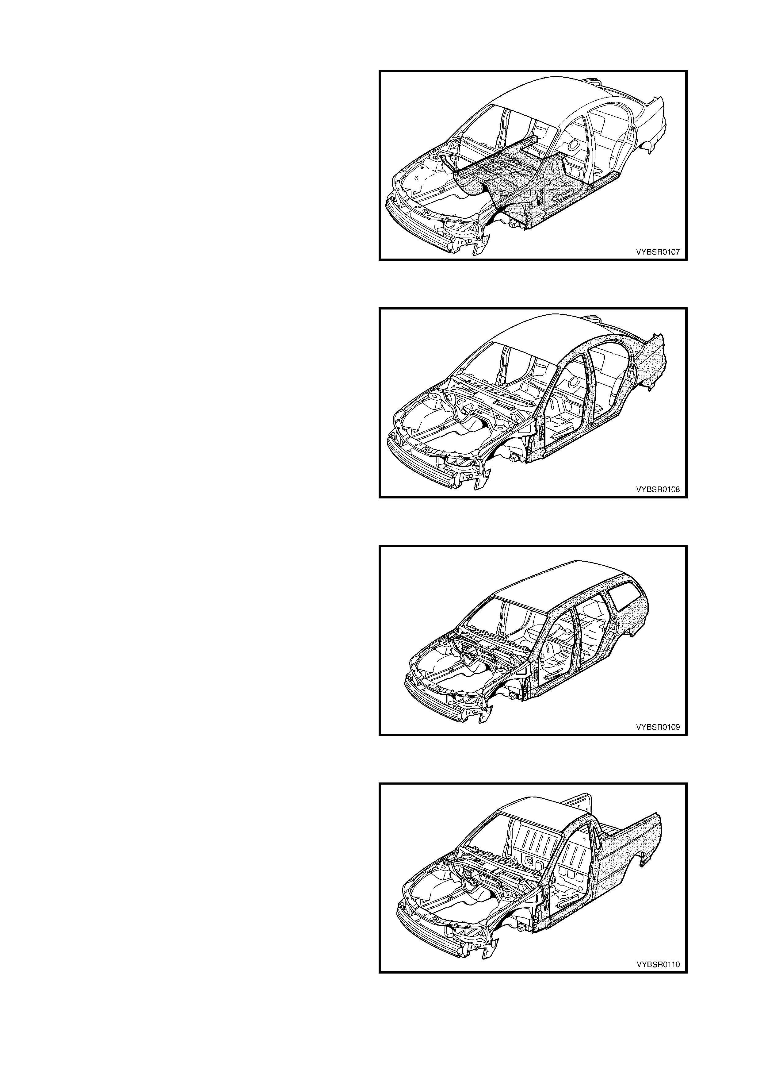
Figure 1-8
SECTION 7A BODY SIDE – SEDAN
Description
1. General Description
2. Service Operations
Figure 1-9
SECTION 7B BODY SIDE – WAGON
Description
1. General Description
2. Service Operations
Figure 1-10
SECTION 7C BODY SIDE – UTILITY
Description
1. General Description
2. Service Operations
Figure 1-11
SECTION 7D BODY SIDE – COUPE
Description
1. General Description
2. Service Operations
Figure 1-12
SECTION 8 DOORS, LIFTGATE & ENDGATE
Description
1. General Description
2. Service Operations
3. Special Tools
Figure 1-13
SECTION 9 ROOF
Description
1. General Description
2. Service Operations
Figure 1-14
SECTION 10A BODY REAR – SEDAN
Description
1. General Description
2. Service Operations
Figure 1-15
3. REPAIR PROCEDURES
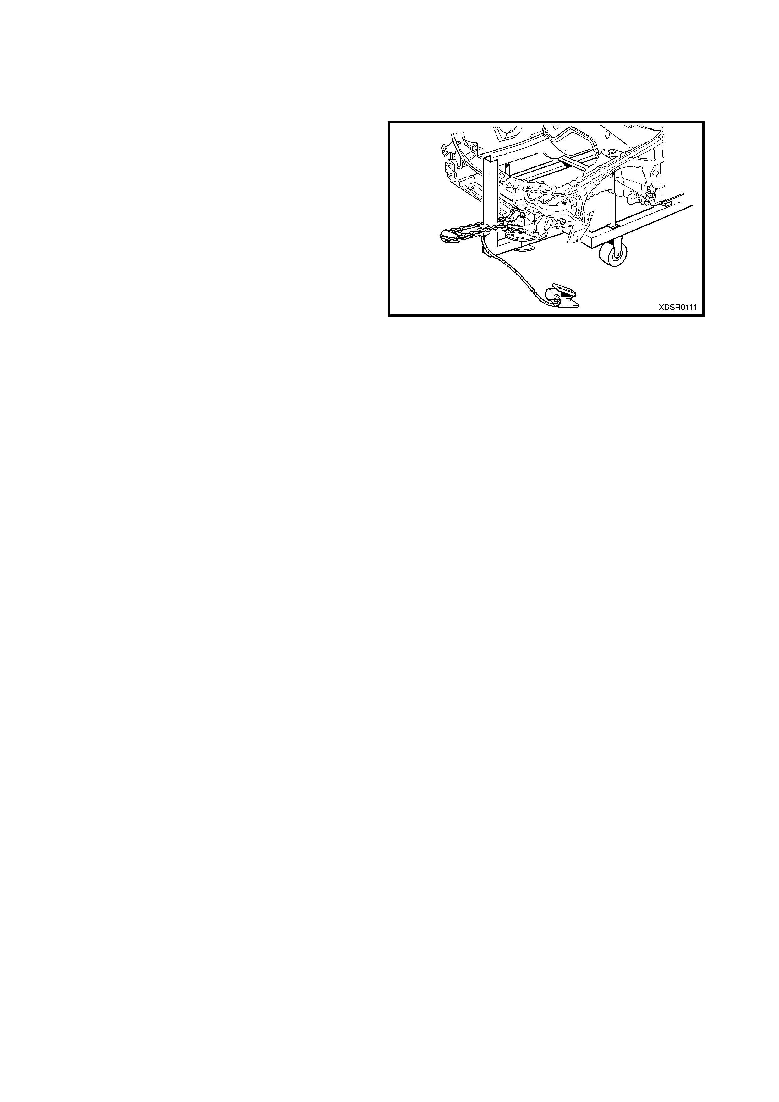
3.1 FRAME S TRAIGHTENING
Fram e st raightening equipm ent should be used initially
to return the vehicle to its approximate shape before
detailed repairs begin. The Equipment should be set
up in such a way as to reverse the direction of impact
that caused the damage. The use of an alignment
bench with either a jigging or measuring system is
prefer red for the r ealignment of VY Series & V2 Series
II vehicles.
CAUTION: Do not allow personnel to stand in the
direction of the pull. Make use of safety chains or
cables to minimise accidents.
Figure 1-19
3.2 ROUGH CUTTING
Damaged panels should be rough cut f rom the vehicle
to make it easier to access and remove spot welds.
NOTE 1: Ensure that r einforcem ent panels are not cut
when the outer panels are being rough cut.
NOTE 2: Check for wiring harnesses, hoses, etc.
behind or inside the panels before performing any
cutting operations.
Figure 1-20
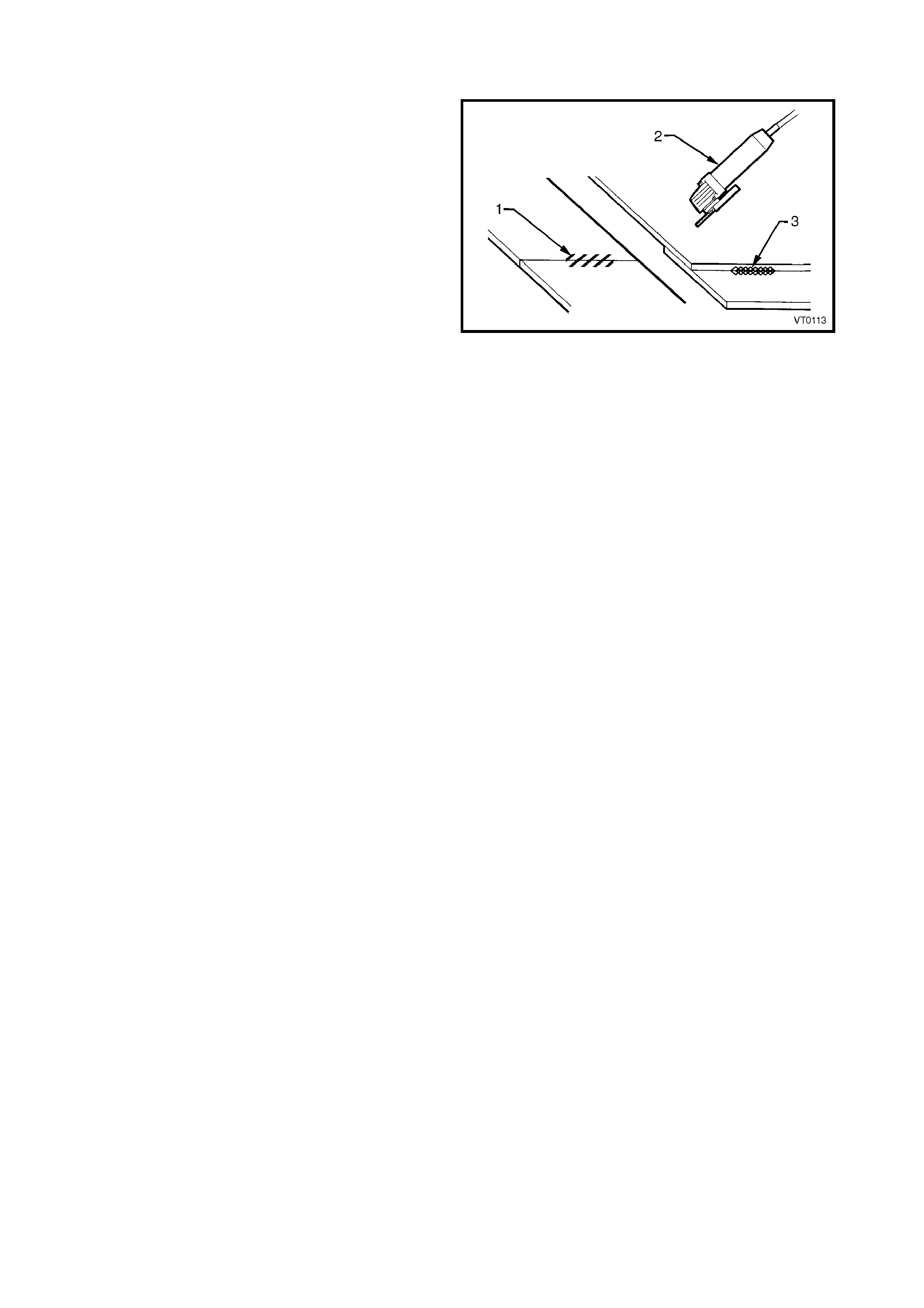
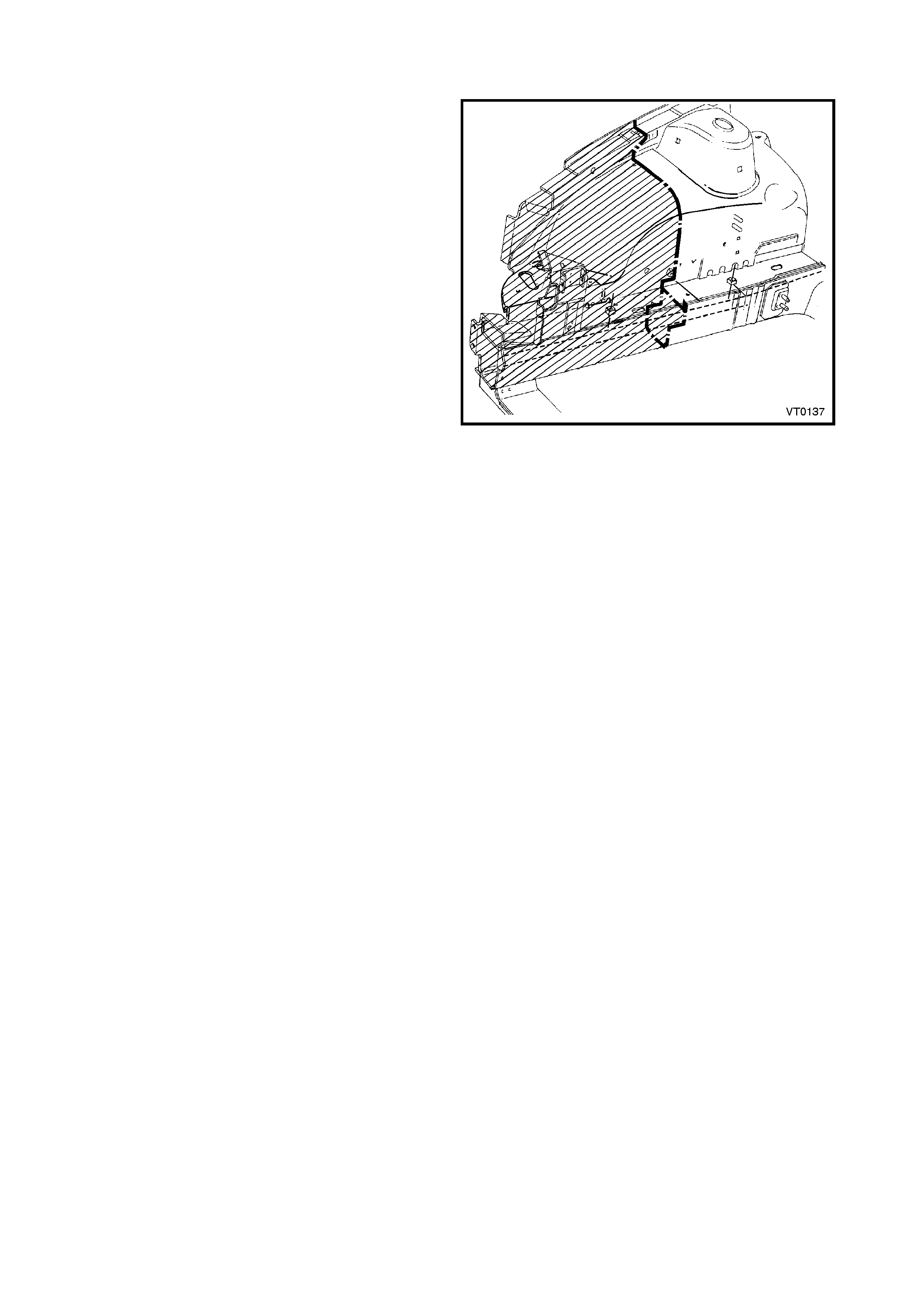
3.3 CUTTING MIG WELDS
MIG welding is used in various places on the body
structure for additional reinforcement and strength.
MIG welds (1) should be cut with a grinder (2) or power
saw. Where practical, a cross sectional view of areas
that may be MIG welded over a tw o panel thickness (3)
is shown.
NOTE 1: Chis elling MIG welds is not recom mended at
any time, as the weld is harder than the surrounding
material, which will tear before the weld is cut.
NOTE 2: Always take care when grinding or cutting,
not to damage either panels adjoining or panels below
the part being removed.
Figure 1-21
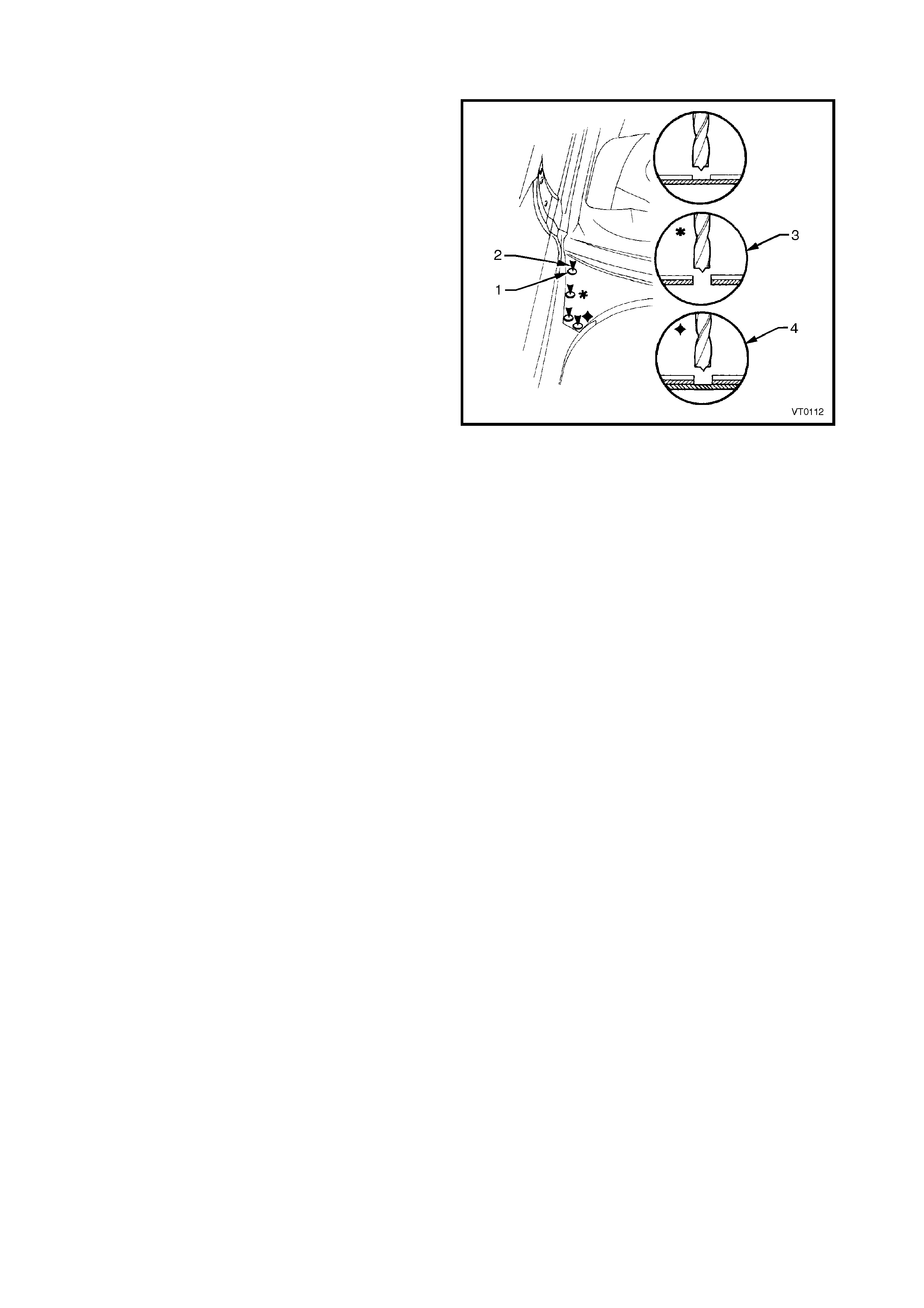
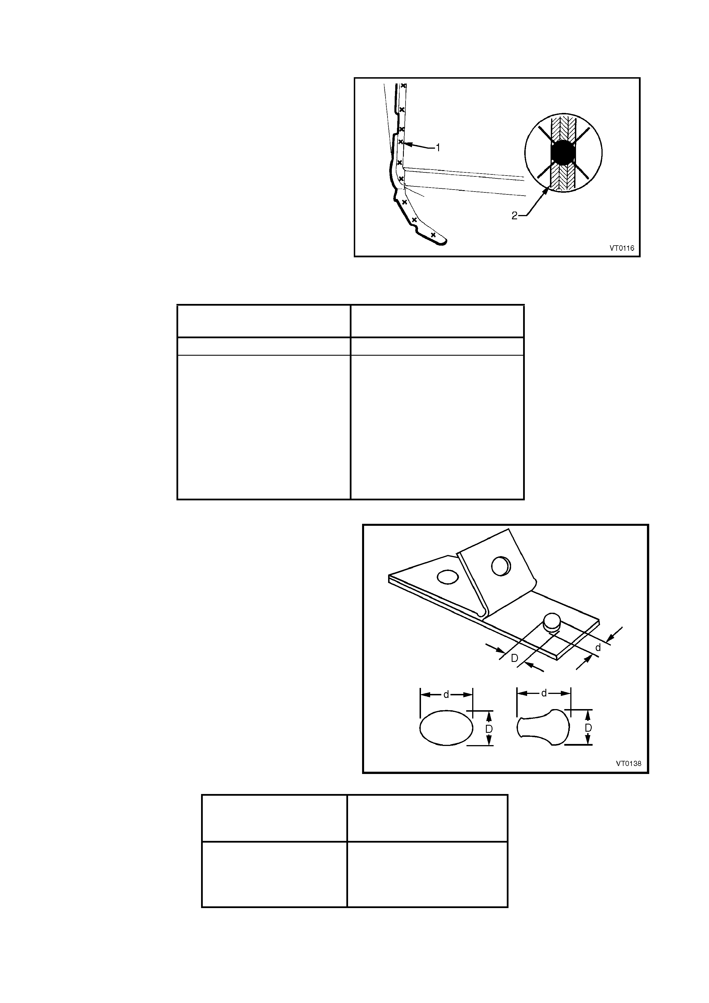
3.4 SPOT WELD CUTTING
Spot welding is the most predominate method of
welding used on the body s tructure. Spot welds should
be cut using a suitable spot cutting tool and a low
speed drill, preferably pneumatic.
Before spot cutting, deeply indent the centre of the
spot weld nuggets using a centre punch and hammer.
It is important to accurately indent the centre of the
spot weld nugget to completely remove the weld.
Referring to Figure 1-22, the symbol for spot cutting is
a circle (1). The arrows in the illustrations (2)
accom panying each oper ation procedure indicate fr om
which side the spot weld should be cut. Do not spot cut
through both panels unless specified to do so (3).
Repair any holes using a MIG welder.
W here it is necessary to spot cut three or m ore joined
panels, an encircled area within the accompanying
illustration will indicate the extent of the spot cut (4).
There will be some incidents where it is necessary to
chisel through spot welds rather than spot cut them.
Use care when ch iselling to avoid distor tion or damage
to the adjacent sheet metal.
Figure 1-22
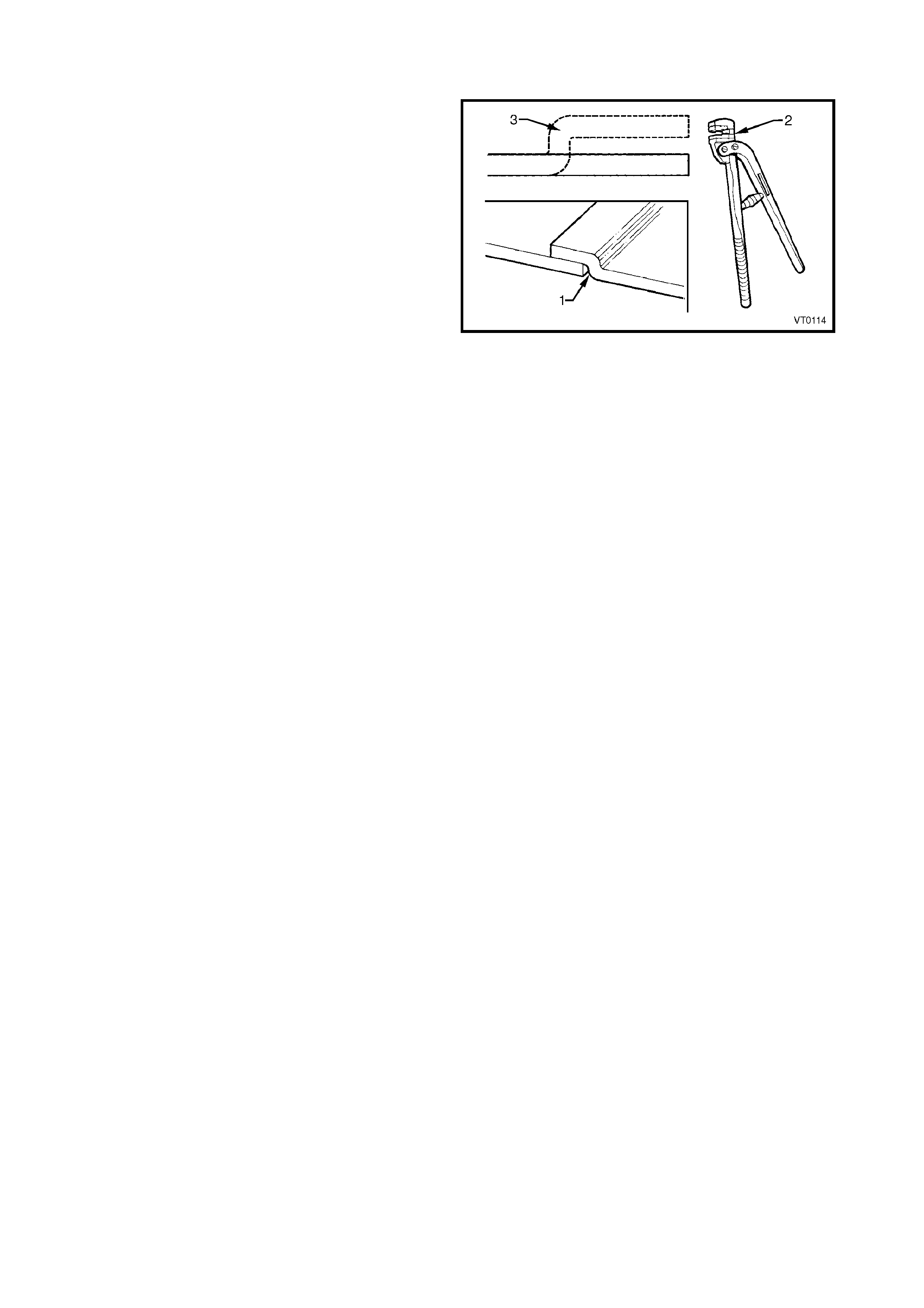
3.5 LAP JOINTING
A lap j oint ( 1) is the m ethod of forming an over -lapping
seam between two panel sections. This should always
be done with an appropriate tool (2), and care should
be taken to maintain any original curvature of the
panel. It may be necessary the make som e incisions at
the corners to form the joint smoothly.
The joggle (3) is the part of the lap joint being formed
to over lap or under lap the adj acent panel. T he joggle
should always be orientated as specified or illustrated.
NOTE: Lap joints should be used wherever possible
when partially replacing panels because of the
additional strength this method provides.
Figure 1-23
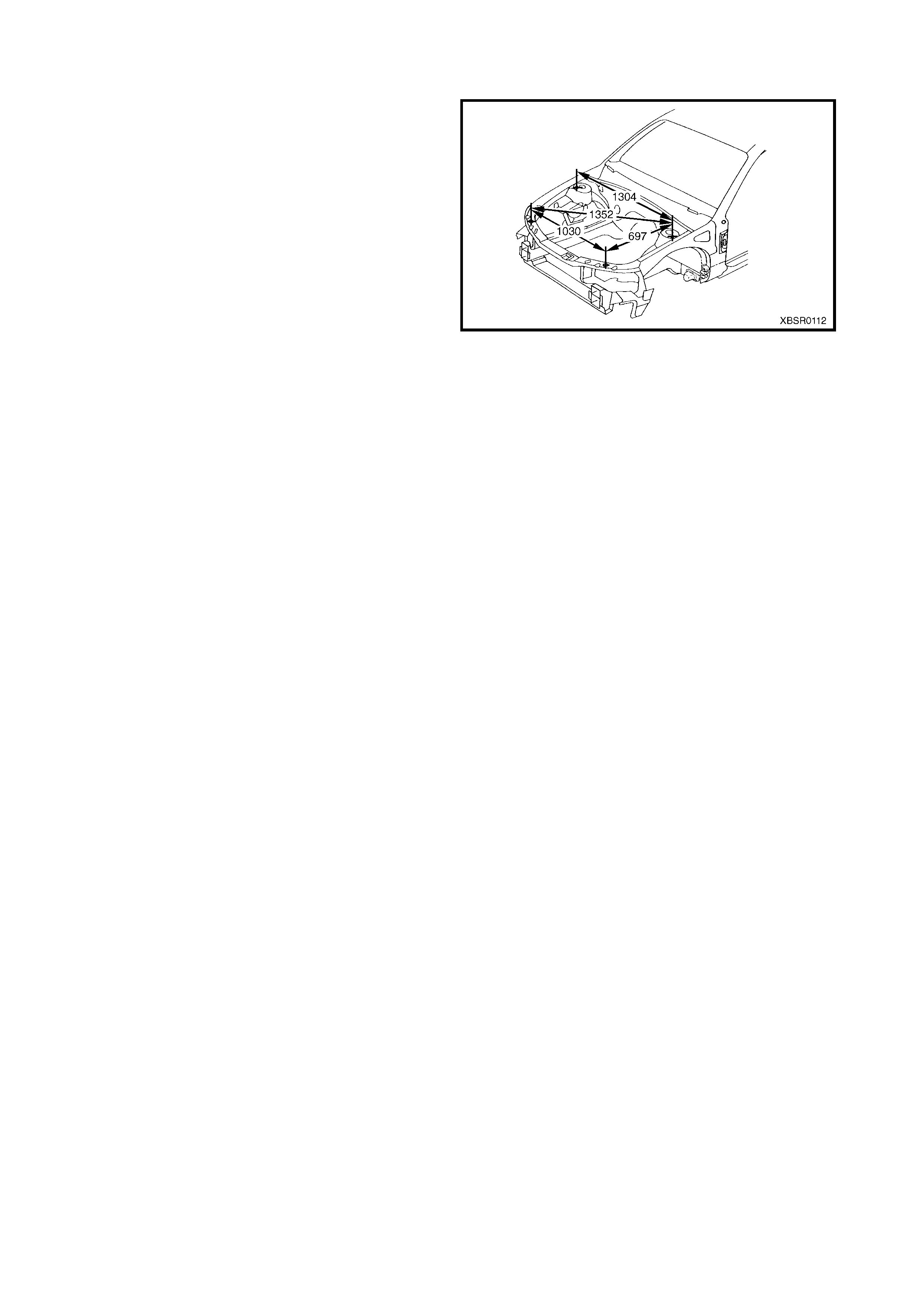
3.6 REPAIRING THE BODY ALIGNMENT
At all times when repairing the vehicle, use a suitable
jigging or measuring system and utilise any tooling
which is either specified or deemed necessary to
maintain the body alignment.
Check the alignment of the body using the charts in
BODY CONSTRUCTION in the following Sections,
3A – Sedan, 3B – Wagon, 3C – Utility or
3D – Coupe. The upperbody dimensions shown are
point to point in a direct line.
The underbody dimensions are projected; the
measuring points are transposed onto a two
dimensional (flat) surface and the measurements are
taken along the one plane.
All dimensions are in millimetres unless otherwise
specified.
NOTE: Always check the body alignment before
welding panels in position.
Figure 1-24

4. WELD REPAIR METHODS
4.1 GENERAL INFORMATION
Spot welding is the preferred method for attaching of panels and should be used whenever possible.
This Supplement indicates where spot welding is practical in repair conditions using portable spot welding
equipment. One repair weld shall be added for each spot weld being repaired, by using either a spot weld or a
plug weld.
Spot welding is not only faster and more efficient than other welding processes, but also causes less rust
formation, reduces the amount of refinishing and causes little distortion to the panel due to heat.
W here the spot welding equipment is not available, or it will not access the required weld position, a plug weld
should be performed. MIG welding should be used for plug welding and also for fusion welding when required.
Gas welding (oxy / acetylene welding) should be avoided as a m ethod of repair. The heat generated in mak ing
the fused joint causes both a decline in the strength of the areas surrounding the welded parts, and also
introduces a high possibility of warping.
CAUTION 1: Always take care when welding. Look behind the parts being welded to avoid additional
damage or poss ible fire.
CAUTION 2: Flammable materials are used in the vehicle, always take care to avoid fire when welding.
Also re fer to 4.5 WELDING LEGEND in this Section.
4.2 SPOT WELDING
Spot W elding (or electric resistance spot welding) is a
method of fusing metal parts together over a small
area.
Two or m ore metal s heets are positioned between two
electrodes (weld tips) where pressure and a large
current are applied. Due to the electrical resistance of
the me tals, a large amount of heat is locally generated
causing the metals to fuse together.
As a guide for weld tip selection and for the
recommended minimum spot weld diameter, the
repairer should refer to Table 1 below. The
recommended minimum spacing between spot welds
is provided in Table 2.
The symbol for spot welding is an " X " (1). Where
multi-ply panels are involved, they will be identified as
shown (2).
Figure 1-25
Governing Metal
Thickness (GMT) Minimum Average Diameter
of Button at Fay ing Plane
mm mm
0.40 – 0.59 3.0
0.60 – 0.79 3.5
0.80 – 1.39 4.0
1.40 – 1.99 4.5
2.00 – 2.49 5.0
2.50 – 2.99 5.5
3.00 – 3.49 6.0
3.50 – 3.99 6.5
4.00 – 4.50 7.0
Table 1
NOTE 1: To determine the minimum weld size for a
two metal st ack, us e the metal thic kness of the thinner
of the two sheets, called the Governing Metal
Thickness (GMT), when referring to Table 1. When
three or more sheets are being welded, the second
thinnest metal thickness in the total stack up will
determine the minimum weld size for each pair of
contacting sheets where fusion is required.
NOTE 2: Nominal sheet thickness is used to
determine GMT.
NOTE 3: Average button (nugget) diameter = (D+d)/2.
NOTE 4: Faying Plane. The mating surface of a sheet
which is in contac t with or in close proxim ity to another
sheet to which it is to be joined.
Figure 1-26
Governing Metal
Thickness
(mm)
Minimum Spot Weld
Spacing Centre to Centre
(mm)
0.7 – 0.9 12.0
1.0 – 1.4 22.0
1.6 25.0
1.8 28.0
Table 2
The efficiency of the spot welding operations during the repair will control the strength and durability of the
finished vehic le. It is recom m ended that the following points be adhered to in or der that a high quality of welding
is achieved.
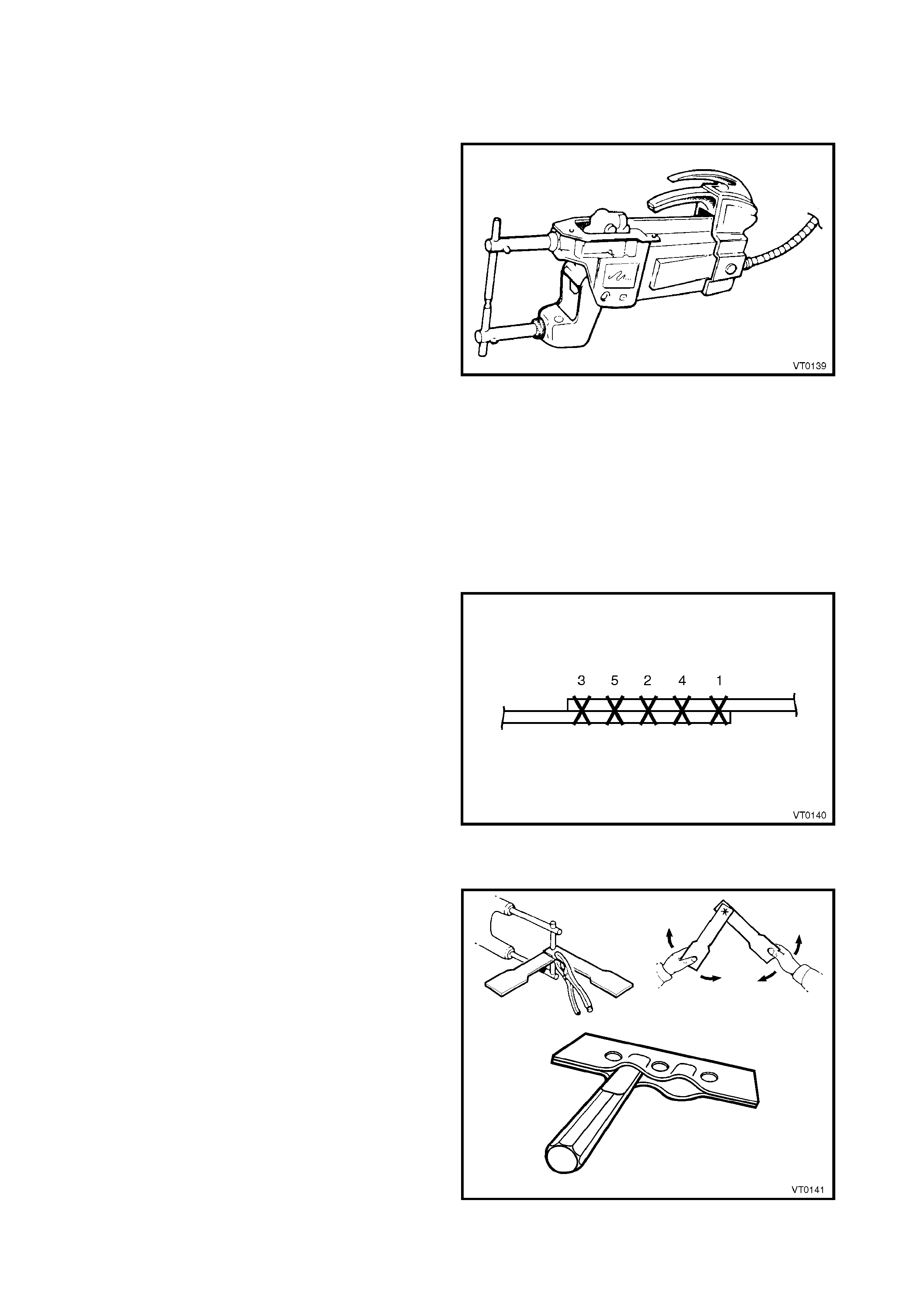
SPOT WELDER
1. The spot welding machine should be adjusted for
the minimum length of arm appropriate to the
particular weld, so that maximum clamping
pressure is available.
2. The electrode tips should be aligned to be parallel
and on the same axis to maintain maximum
pressure and weld alignment.
3. The correct welding tips should be employed as
per Table 1 on the previous page.
Figure 1-27
PANEL CONDITION
1. The panel surface must be free of paint film, rust, dirt and other contaminates so that current flow will be
sufficient for proper fusion.
2. The m ating surfac es should be prepared suc h that there are no gaps between the surfaces . Current flow is
reduced considerably by poor contact.
3. All mating surfaces must be treated with a weld through primer to prevent corrosion in this inaccessible area.
The correct primer has high conductivity to facilitate the weld. Refer to 5 BODY SEALING, ADHESIVES &
DEADENERS in the following Sections, 3A – Sedan, 3B – Wagon, 3C – Utility or 3D – Coupe.
NUMBER OF WELDS
1. The same number and similar position of spot
welds should be used when replacing the panel, as
was used during manufacture. It is important to
maintain the original structural strength of
the vehicle, par ticular ly because of the implications
in deployment of the SRS system. Refer to
Section 2, PRECAUTIONS in this Supplement for
further information on the SRS.
2. The required spot weld diameter is specified in
Table 1, earlier in this Section.
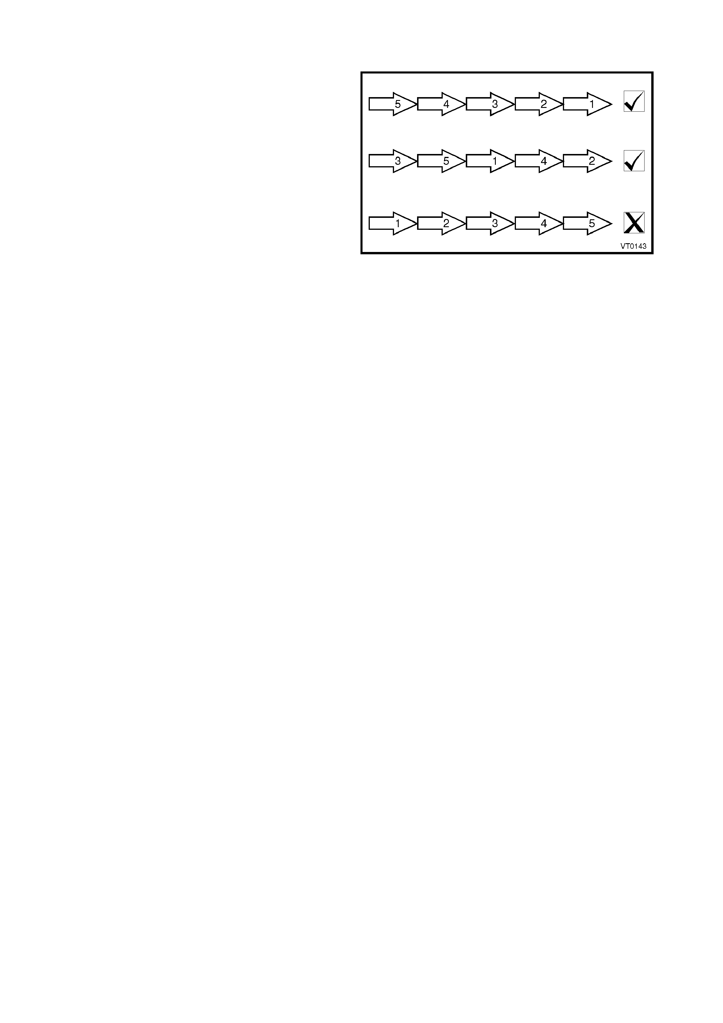
3. Spot welding too closely spaced weakens the
welds due to the shunt effect of the current. Apply
a non-sequential welding procedure.
Figure 1-28
WELD TESTING
1. Prior to welding, two (or more) pieces of same
thickness panel should be test welded, using the
intended weld settings. The weld should then be
destroyed by twisting the pieces. If the settings are
correct, there should be a weld button (nugget)
pulled out of one test piece with the dimensions
recommended. If not, the weld settings must be
adjusted, and the test repeated.
2. Completed weld sections may be tested using a
hammer and chisel (or flat bladed screwdriver).
The testing should cease once the size of the
nuggets can be determined, and the welds should
still be intact.
NOTE: The test section must be returned to the
correct shape after testing.
Figure 1-29
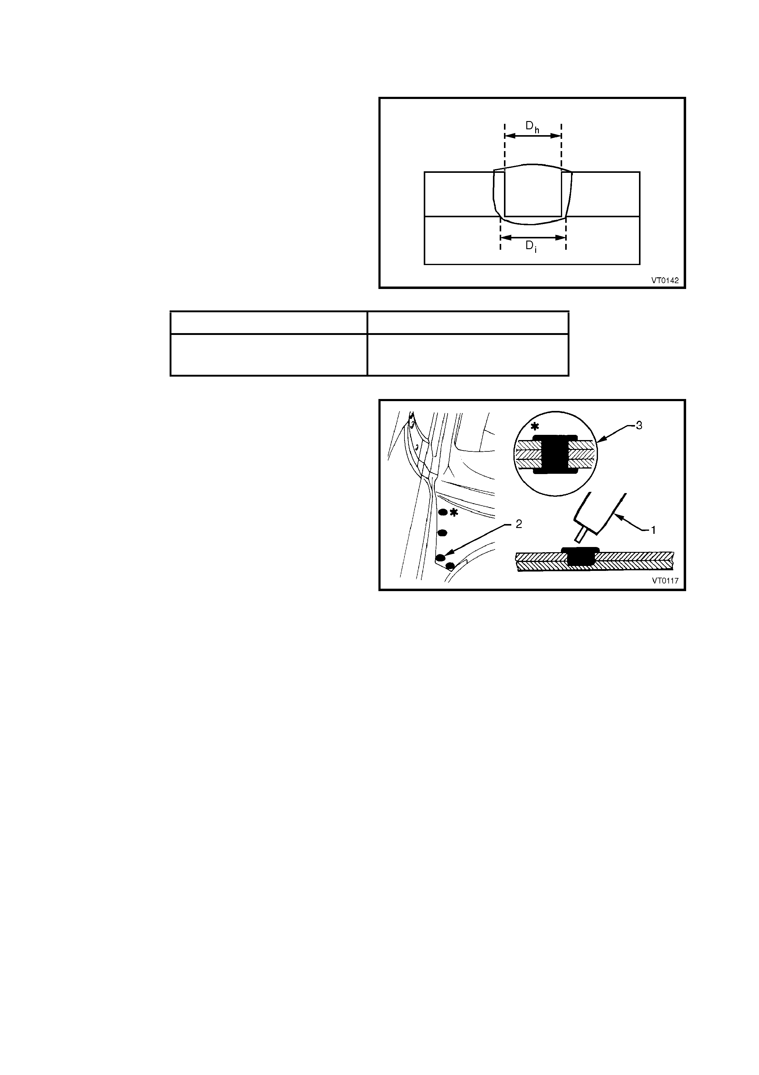
4.3 PLUG WELDING
In this Supplement, plug welding describes a weld
made inside a pre-drilled hole in one panel of a lap
joint, fusing that panel to the other in the joint.
Plug welding should be perf ormed us ing a MIG welder
of suitable capacity. The hole is filled with a puddle of
MIG weld, ensuring penetration into the panel below.
The weld interface diameter, Di must be at least equal
to the hole diameter, Dh. The nominal hole diameters
are given in Table 3.
Figure 1-30
Top Sheet Thickness (mm) Nominal Hole Diameter (mm)
0.40 – 1.0 6.0
1.0 – 2.0 8.0
Table 3
For plug welds with a top sheet thickness less than
2 mm, the welds shall be at leas t filled to the surface at
the hole circumference. For a thickness greater than
2 mm , all plug welds shall be filled to at least 2 m m or
90% of the top sheet thick ness ( whichever is larger) at
the hole circumference, unless otherwise specified.
Plug welding is best performed with a MIG welder (1)
of sufficient capacity. The required holes, as
recom m ended in Table 3, ar e drilled in the appropriate
panel which is secured in position using clamps.
The weld setting and wire gauge are at the discretion
of the operator, and theref ore only qualif ied individuals
should perform welding tasks during repairs.
The symbol for plug welding is a solid black dot (2) and
the plug welding of m ulti-ply panels will be identified as
shown (3).
Figure 1-31
4.4 FUSION WELDING
Fusion welding is a welding method in which the
metals to be joined are raised to a molten state and
fused together. Molten filler metal may also be
deposited at the point of welding to fuse with the base
metal/s.
Fusion welding repairs should be performed using a
MIG welder. Both butt and lap joint methods are
utilised, as specified in the repair procedures.
CAUTION: Always take care when welding. Look
behind the parts being welded to avoid additional
damage or possible fire. Use an assistant for this
purpose if required.
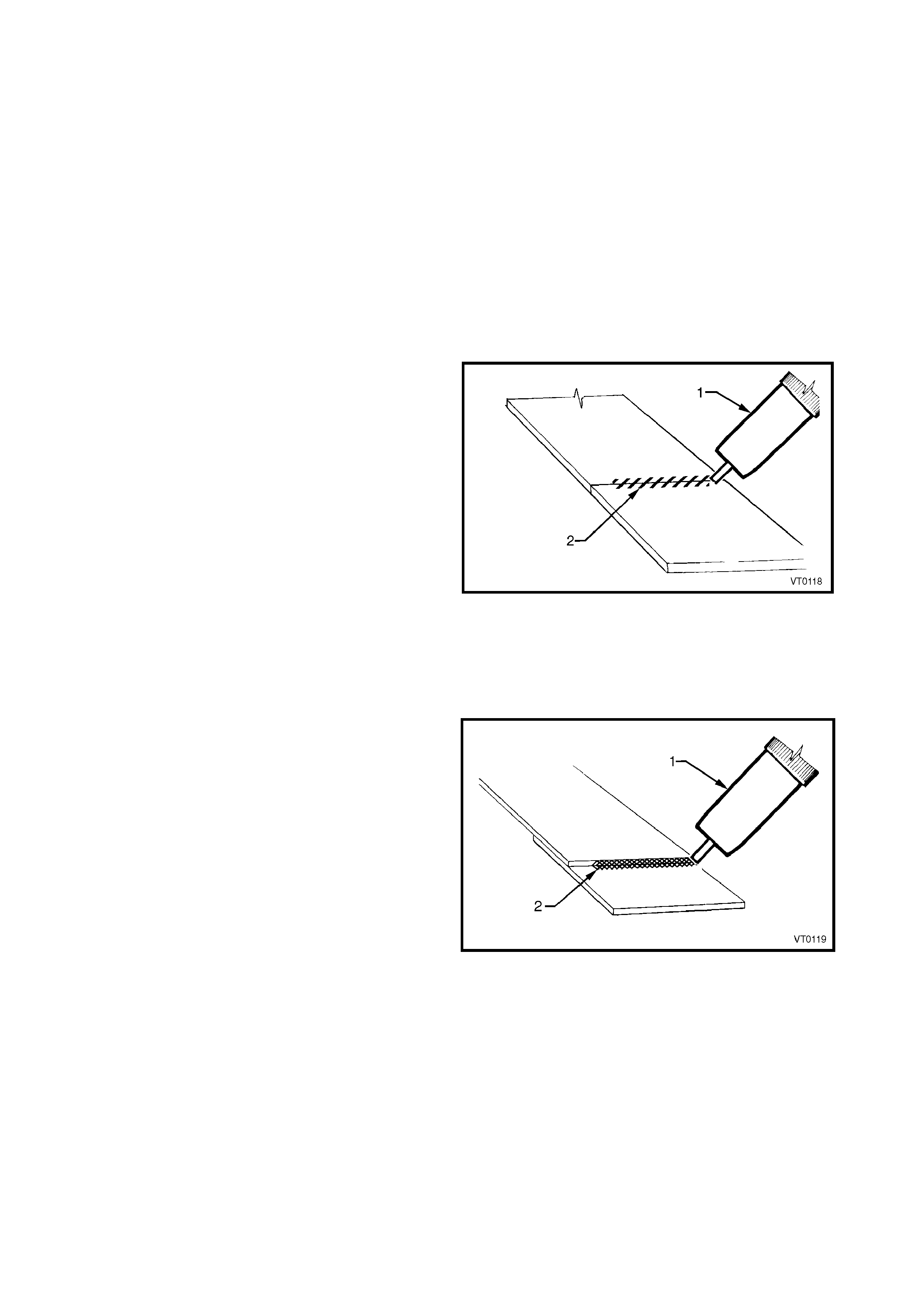
BUTT WELDED JOINTS
Joining two panels together on the same plane is butt
welding. There should be no gaps between the
adjoining edges, so that a strong weld is obtained.
A MIG welder (1) should be used for butt welding, as it
provides localis ed heat in c omparis on to other f orms of
welding (especially in com paris on to gas welding). T h is
localisation of heat significantly reduces panel
deformation.
An industrial MIG welder of suffic ient capacity m ust be
used in order to obtain the correct weld penetration
and maintain the strength and integrity of the structure.
The weld settings and the wire gauge are at the
discretion of the operator and therefore only qualified
individuals should perform the welding tasks on
repairs.
The s ymbol used in this Supplem ent f or butt welding is
shown (2).
Figure 1-32
LAP WELDED JOINTS
Where panels overlap or are placed together with flat
surfaces mating, fillet welding should be used to form
this lap joint. It is important that the gap between the
surfaces is minimal, to ensure a satisfactory result.
For the same reasons as outlined previously, a MIG
welder (1) of suitable capacity should be used for lap
welded joints.
The symbol for fillet welding is shown (2).
Figure 1-33
BRONZE WELDS
Bronze welding is used to complete the lock pillar
join of the rear quarter panel to the door opening
frame assembly on Coupe vehicles, refer to
Section 7D BODY SIDE – COUPE.
Other than for the aforementioned, bronze welding
should not be us ed in vehicle repair procedures as it is
not considered strong enough for the welding of body
sections or panels.
WARP PREVENTION ON LONG WELDS
A long continuous weld is likely to cause warping and
residual stresses. Various weld sequences can be
utilised to minimise this effect when long sections of
weld are required.
Figure 1-34
4.5 WELDING LEGEND
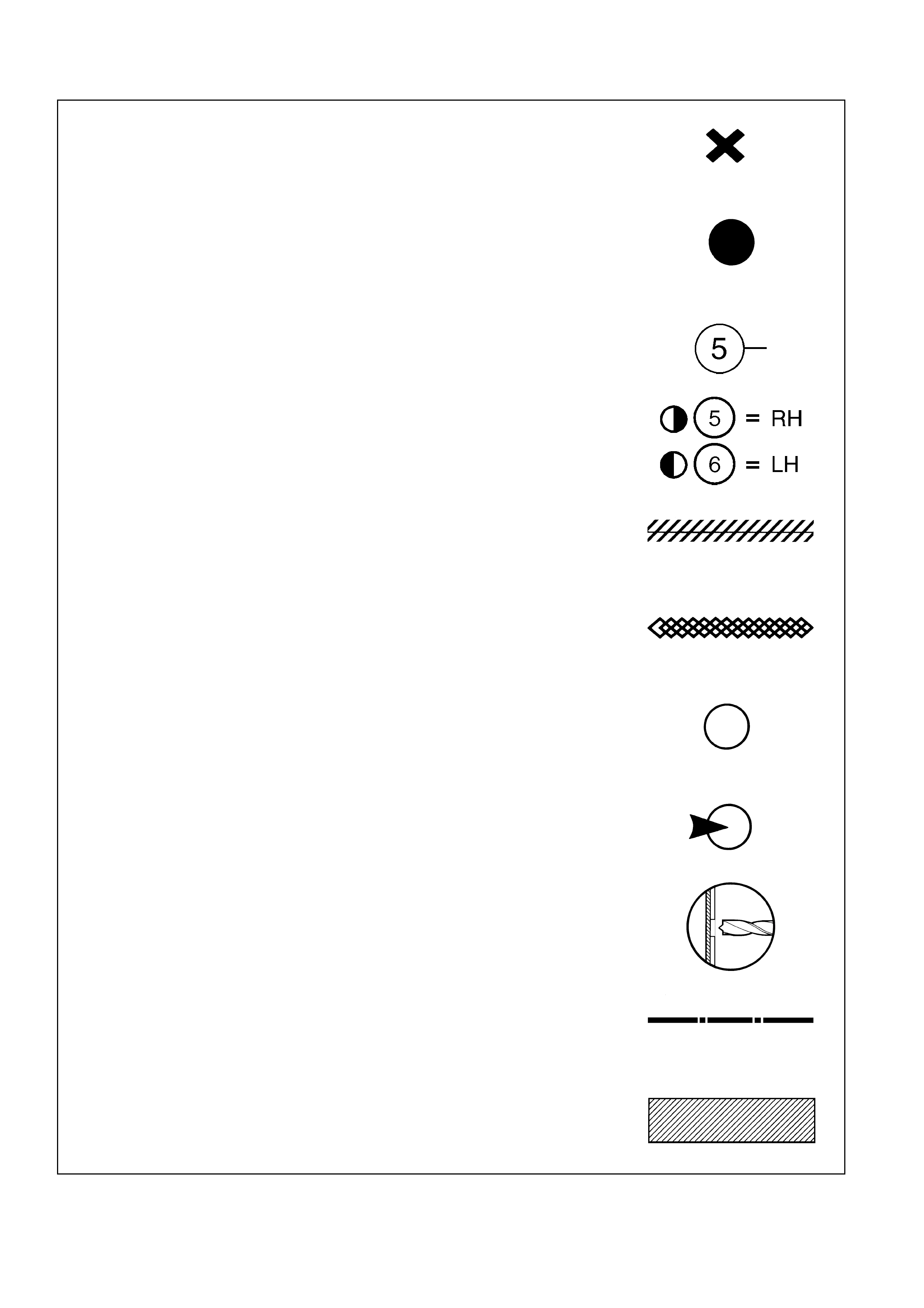
SPOT WELDING...............................................................................................
PLUG WELDING ..............................................................................................
NUMBER OF WELDS ......................................................................................
NUMBER OF WELDS (OR DRILLS) ON EACH SIDE OF VEHICLE..............
BUTT WELDING...............................................................................................
FILLET WELDING............................................................................................
SPOT WELD TO BE CUT ................................................................................
SPOT CUT FROM THIS SIDE..........................................................................
SPOT CUT TO THE DEPTH INDICATED........................................................
CUT THE PANEL ALONG THE LINE SHOWN ...............................................
DISCARD THIS PORTION ...............................................................................