SECTION 6 - CABIN FLOOR & UTILITY
SEATBACK ASSEMBLY
IMPORTANT
Before performing any Service Operation or other procedure described in this Section, refer to
Section 00 CAUTIONS AND NOTES and Section 2 PRECAUTIONS in this Supplement for correct
workshop practices with regard to safety and/or property damage.
CAUTION
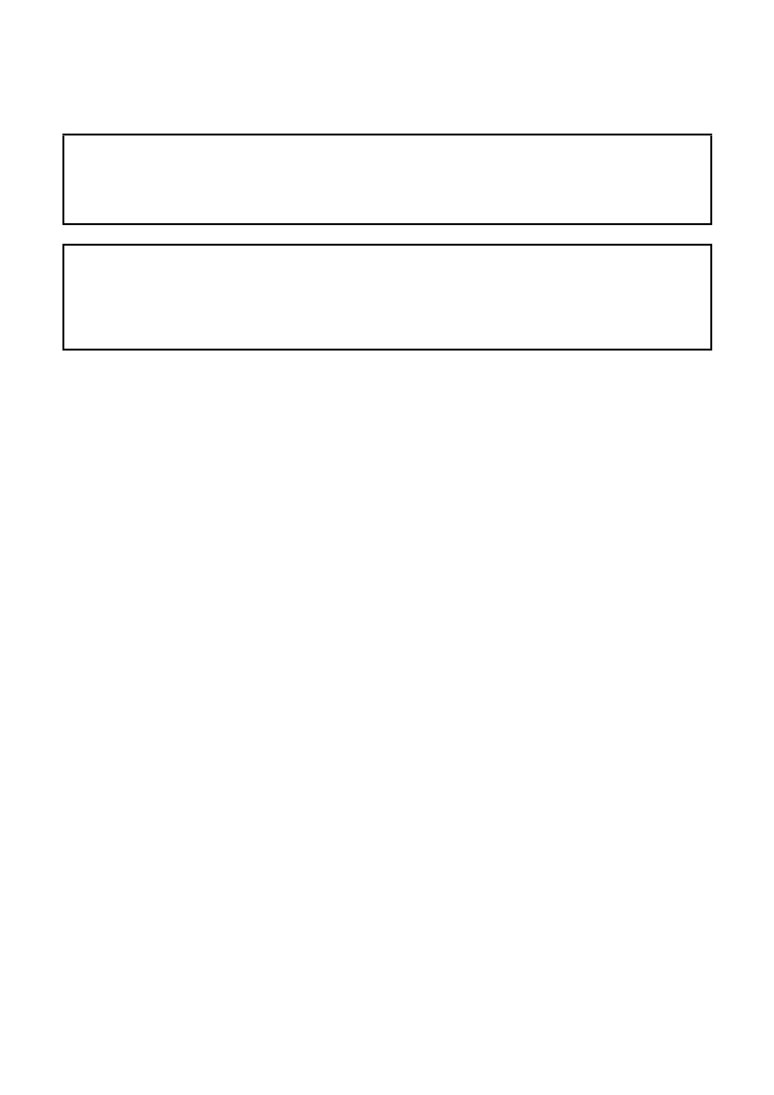
The Structure of the M Y 2003 VY & V2 Series II body shell has been developed using complex design
and development techniques. In addition to meeting all required standards, the v ehicle body is also a
critical part of the overall safety systems. It is therefore imperative the repair procedures described
here are adhered to during all vehicle body repairs.
1. GENERAL DESCRIPTION
1.1 CABIN FLOOR COMPONENTS
1.2 UTILITY SEATBACK ASSEMBLY COMPONENTS
2. SERVICE OPERATIONS – CABIN FLOOR
2.1 FRONT FLOOR PANEL EXTENSION – REPLACE
REMOVE
REPLACE
2.2 FRONT FLOOR PANEL EXTENSION –
PARTIAL REPLACE
REMOVE
REPLACE
2.3 FRONT FLOOR PANEL ASSEMBLY –
REPLACE
REMOVE
REPLACE
2.4 INNER ROCKER PANEL ASSEMBLY –
REPLACE
REMOVE
REPLACE
2.5 TRANSMISSION SUPPORT BRACKET –
REPLACE
REMOVE
REPLACE
2.6 SEAT INNER BRACKET ASSEMBLY –
REPLACE
REMOVE
REPLACE
2.7 SEAT OUTER BRACKET ASSEMBLY –
REPLACE
REMOVE
REPLACE
2.8 PROPELLER SHAFT HANGER ASSEMBLY –
REPLACE
REMOVE
REPLACE
3. SERVICE OPERATIONS – UTILITY
SEATBACK ASSEMBLY
3.1 LOAD COMPARTM ENT EXTENSION OUTER
PANEL & BRACKET – REPLACE
REMOVE
REPLACE
3.2 FRONT SEAT BACK PANEL OUTER –
REPLACE
REMOVE
REPLACE
3.3 FRONT SEATBACK PANEL – REPLACE
REMOVE
REPLACE
3.4 FRONT FLOOR REAR EXTENSION
ASSEMBLY – REPLACE
REMOVE
REPLACE

1. GENERAL DESCRI PTI O N
This Sect ion desc ribes the r eplacem ent procedur es f or the cabin f loor com ponents of the MY 2003 VY & V2 Series
II body structure as well as the seatback assembly components for MY 2003 VY Series Utility vehicles.
For the servicing of the rear floor components refer to Section 10A (Sedan), 10B (Wagon), 10C (Utility) or
10D (Coupe).
Removal of bolt-on panels and mechanical components is not covered. For information on the removal of these
parts, reference must be made to the appropriate Section in the MY 2003 VY & V2 Series II Service Information.
NOTE: It is imperative that the correct body adhesives, sealers, deadeners and cavity waxes are used when
repairing the body structure of MY 2003 VY & V2 Series II vehicles. Refer to 5. BODY SEALING, ADHESIVES &
DEADENERS and 6. CAVITY W AX in Section 3A (Sedan), 3B (Wagon), 3C (Utility) or 3D (Coupe) for details of
the correct materials and their commercially available equivalents.
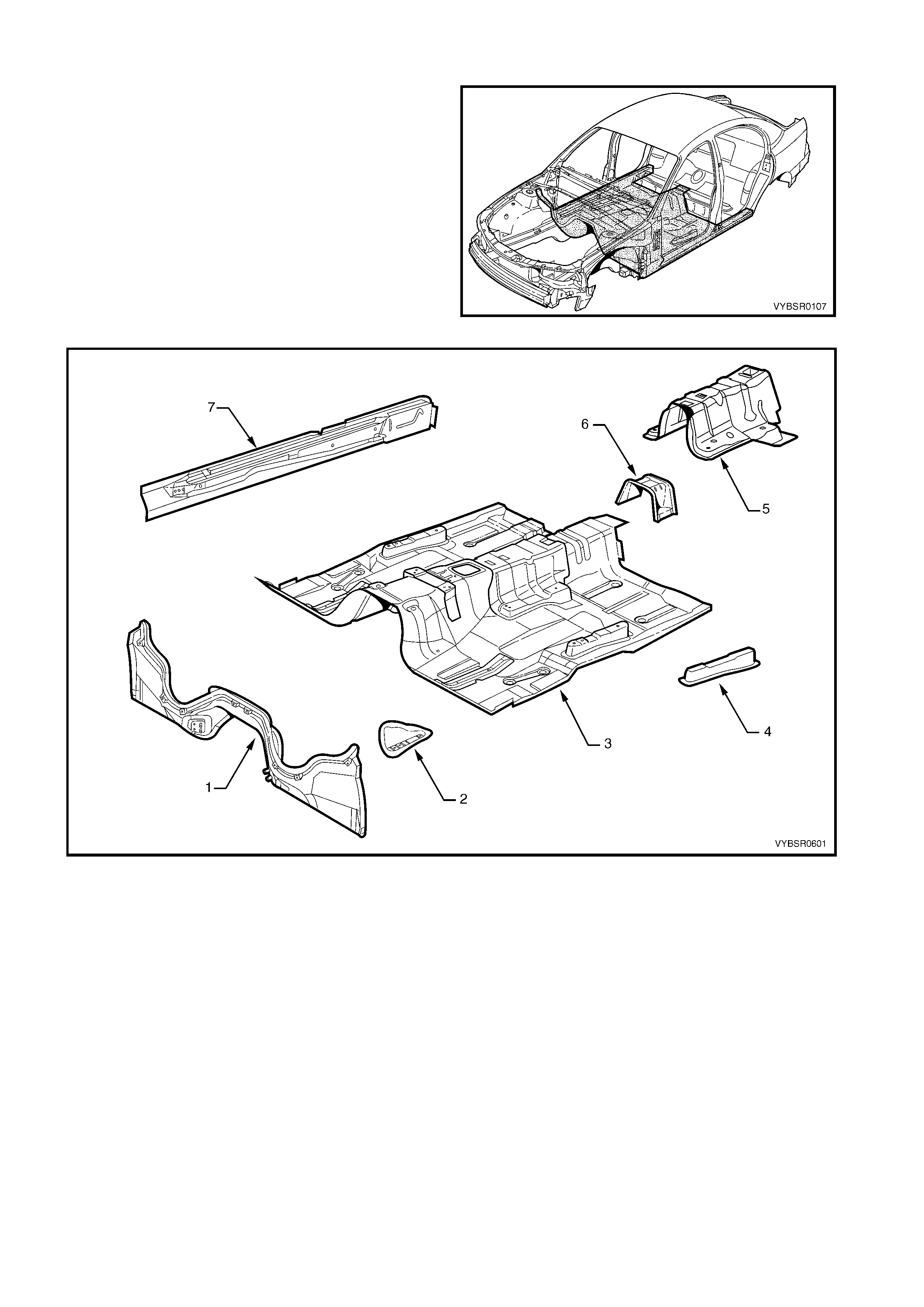
1.2 CABIN FLOOR COMPONENTS
The shaded components in Figure 6-1 are the cabin
floor components dealt with in this Section.
The components and assemblies shown in Figure 6-2
are the parts serviced for MY 2003 VY & V2 Series II
vehicles which form the basis of the repair
procedures in this Section. For a detailed view of the
body components, refer to Section 3A (Sedan),
3B (Wagon), 3C (Utility) or 3D (Coupe).
NOTE: Always refer to your Authorised Retailer for
spare parts availability configurations.
Figure 6-1
Figure 6-2
Legend
1. Front Floor Panel Extension
2. Transmission Support Bracket
3. Front Floor Assembly
4. Seat Outer Bracket Assembly
5. Seat Inner Bracket Assembly
6. Propeller Shaft Hanger Assembly
7. Inner Rocker Panel Assembly
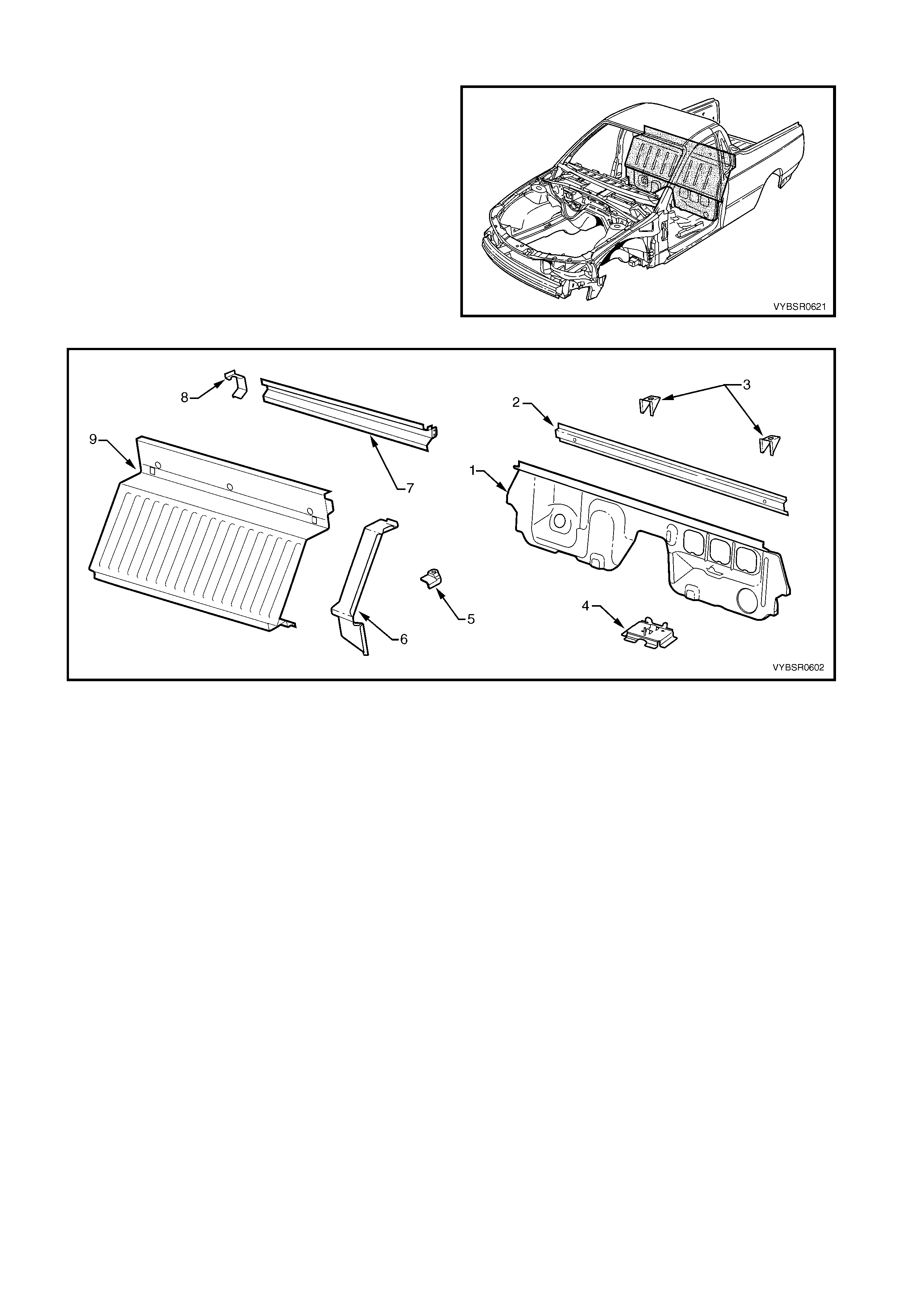
1.3 UTILITY SEATBACK ASSEMBLY COMPONENTS
The shaded components in Figure 6-3 are the
seatback assembly components fitted to MY 2003 VY
Series Utility vehicles dealt with in this Section.
The components and assemblies shown in Figure 6-4
are the parts serviced which form the basis of the
repair procedures in this Section. For a detailed view of
the body components, refer to Section 3C.
NOTE: Always refer to your Authorised Retailer for
spare parts availability configurations.
Figure 6-3
Figure 6-4
Legend
1. Front Floor Rear Extension Assembly
2. Front Floor Rear Extension Reinforcement
3. Fuel Tank Bracket Assembly
4. Jack Stowage Bracket
5. Front Tie Down Bracket
5. Front Seat Back Panel Outer
6. Load Compartment Extension Outer Panel
7. Load Compartment Extension Panel Bracket
8. Front Seatback Panel
2. SERVICE OPERATIONS – CABI N FLOOR
2.1 FRONT FLOOR PANEL EXTENSION – REPLACE
REMOVE
1. Remove the adjacent bolt-on panels and
components as described in the appropriate
Section of the MY 2003 VY & V2 Series II Service
Information.
2. Secure the vehicle on a suitable fixture. As a
minimum, support the appropriate structural
sections of the vehicle on safety stands.
3. Remove the dash panel assembly, refer to
Section 5 COCKPIT MODULE.
4. Remove the adjoining panels as required, refer to
the relevant Section in this Supplement.
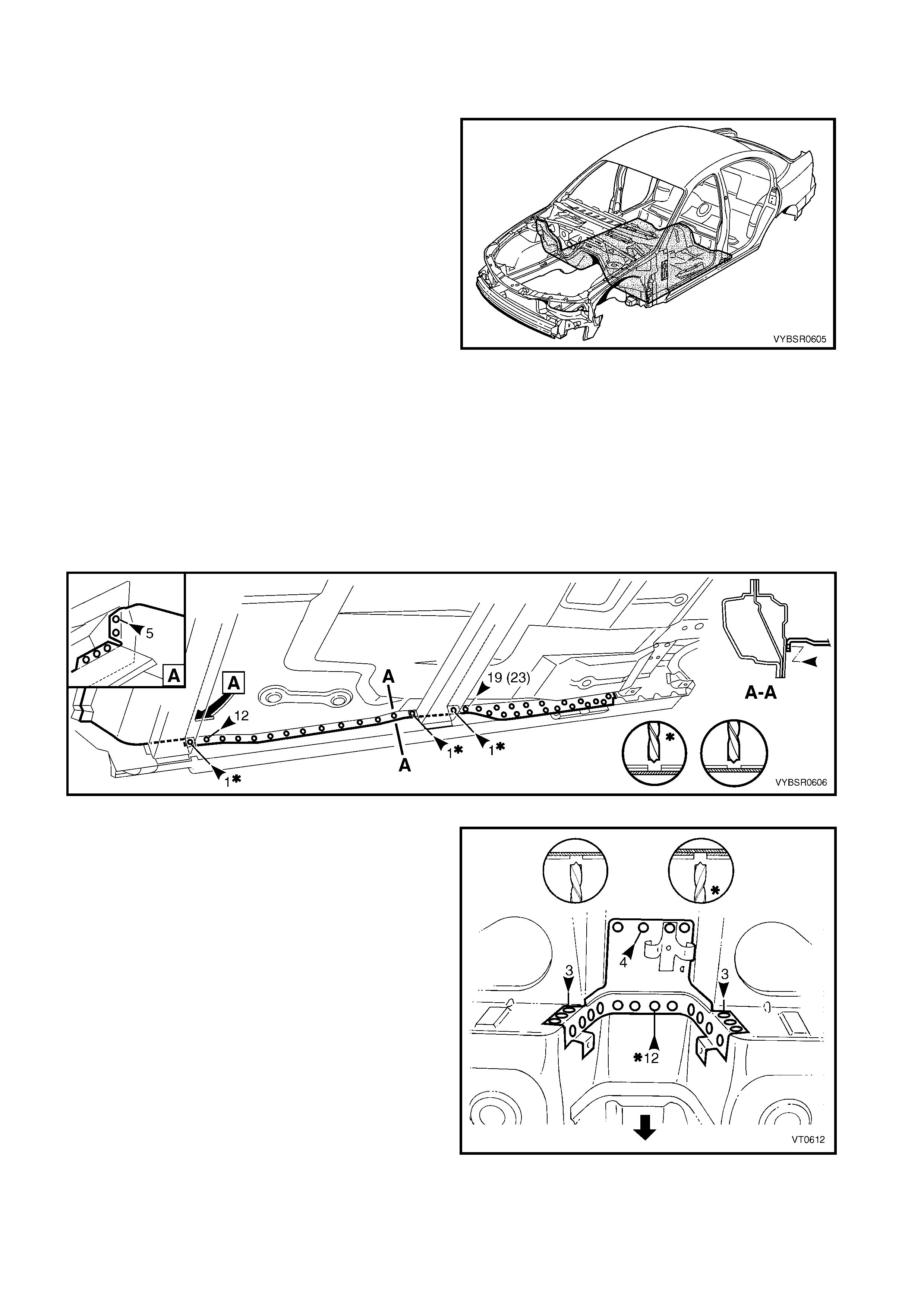
5. Using a scraper and heat gun, remove the body
sealer and deadener from the front floor and floor
extension attaching areas. Figure 6-5
6. Spot cut the welds on each side of the vehicle,
attaching the front floor panel extension to the front
side rail assembly, front wheelhouse panel
assembly and front floor panel assembly.
Figure 6-6
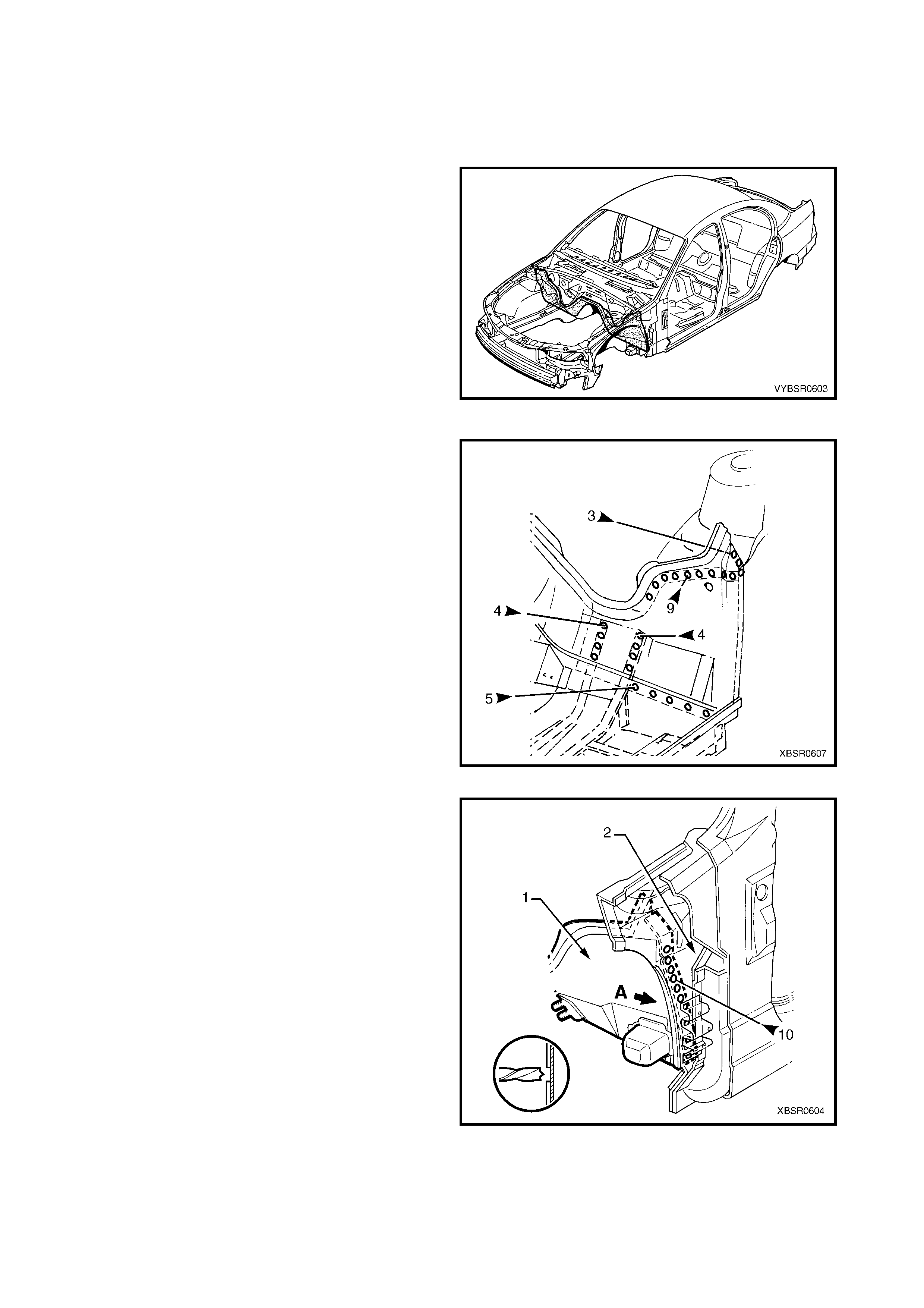
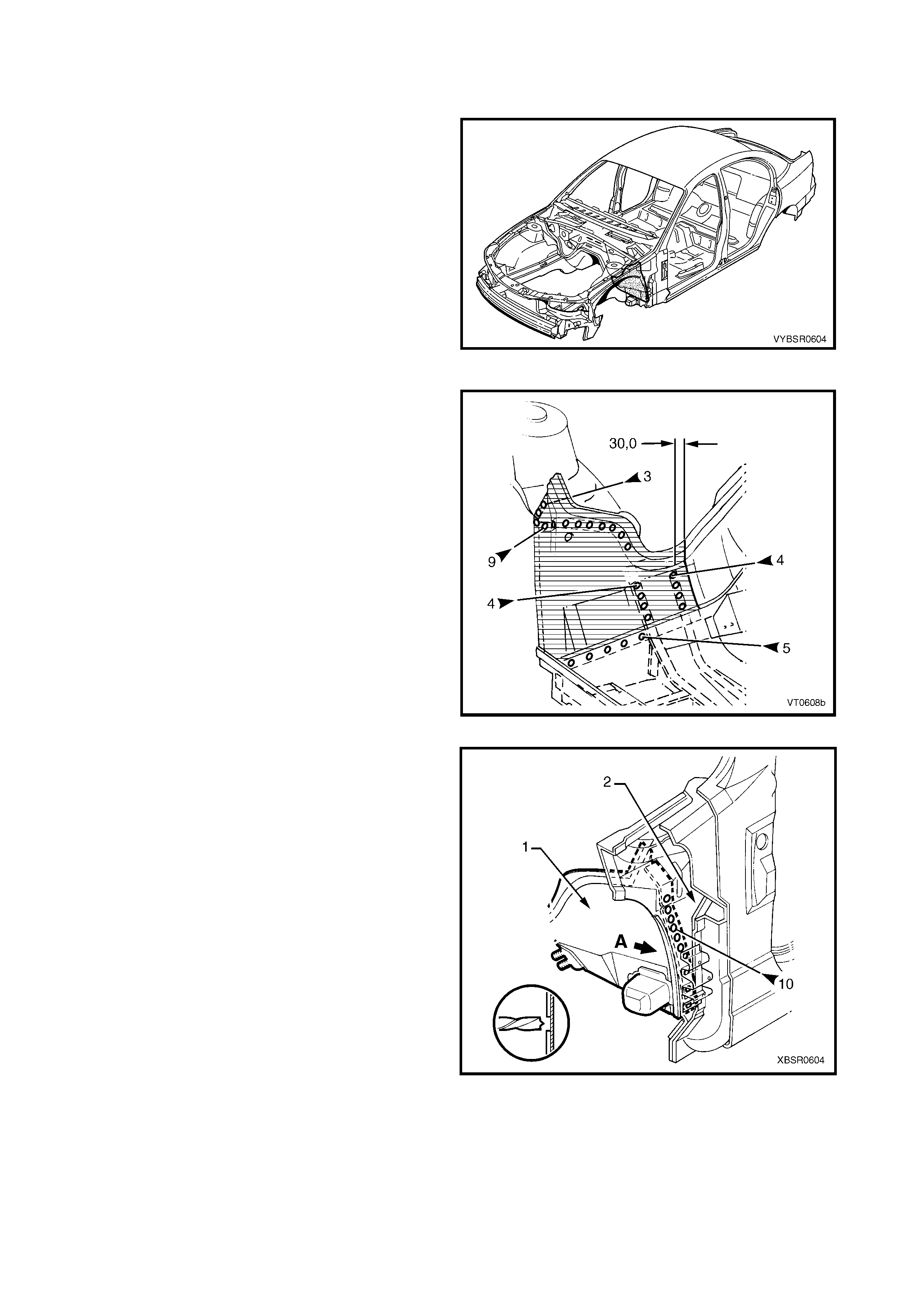
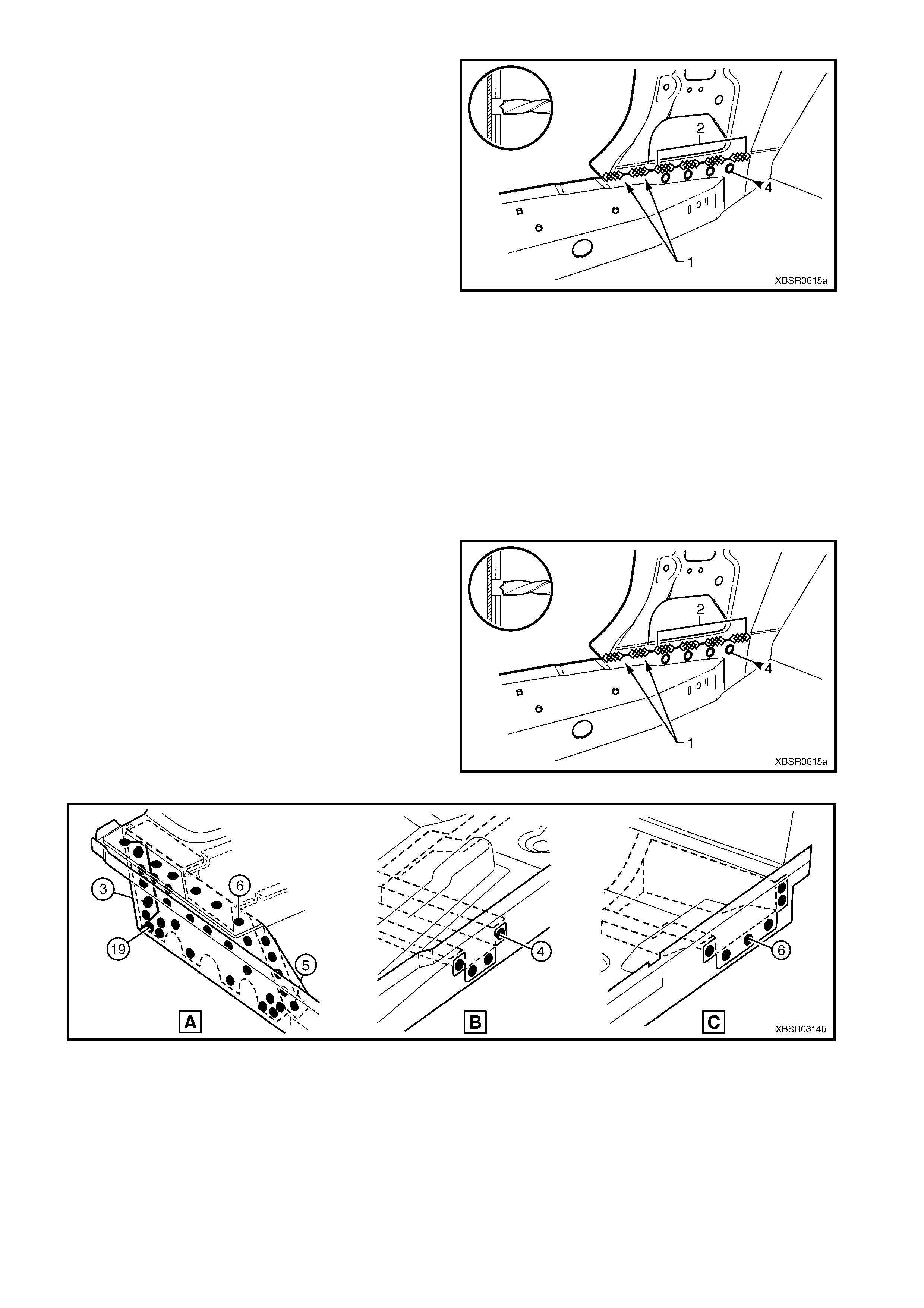
7. Spot cut the welds on each side of the vehicle,
attaching the front floor panel extension (1) to the
hinge pillar inner panel (2) from the direction
shown A.
Figure 6-7
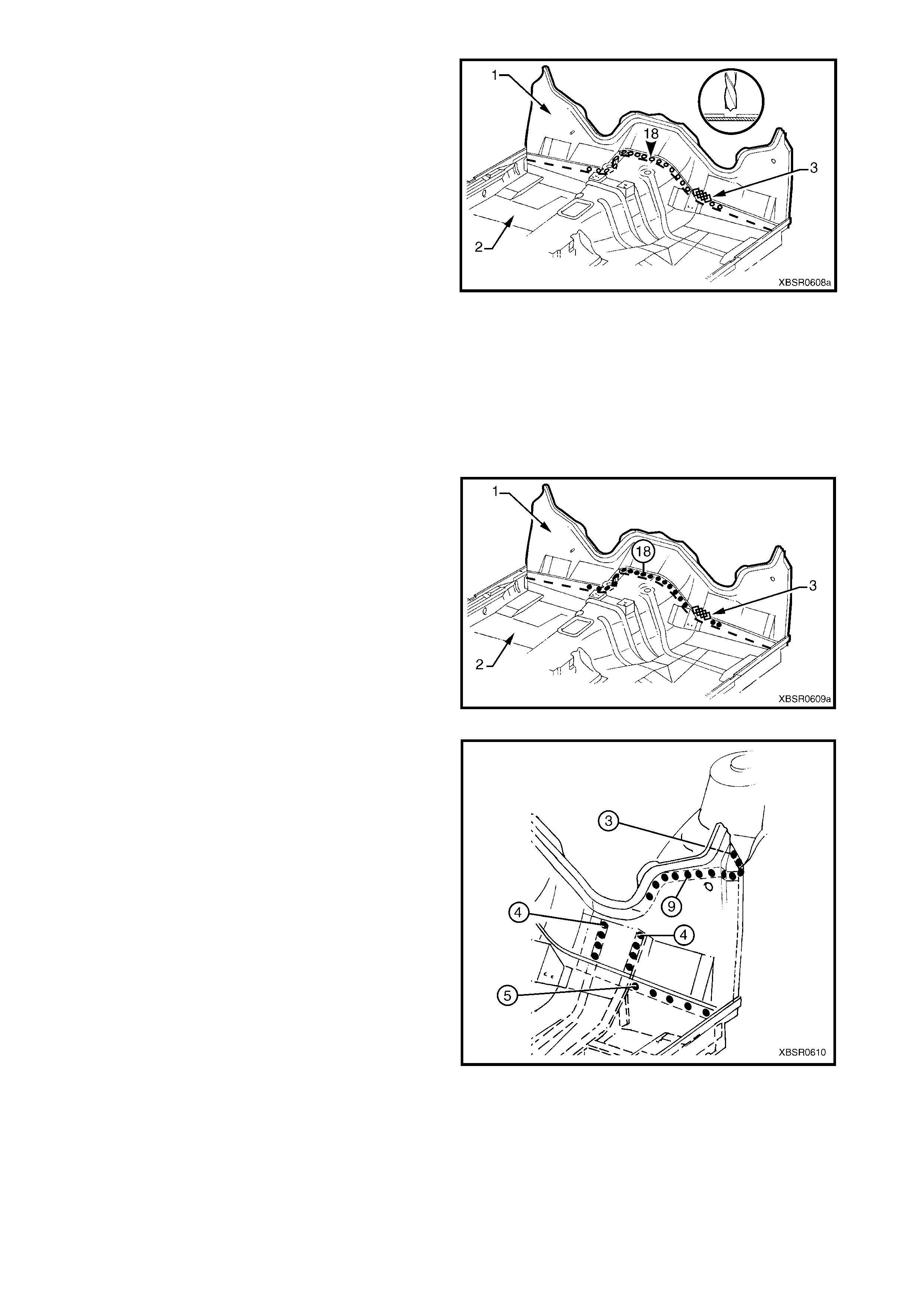
8. Spot cut the welds attaching the front floor panel
extension (1) to the front floor panel assembly (2).
9. Remove the MIG weld (3) from near the footrest
bracket.
NOTE: Some models may not have this weld.
10. Remove the front floor panel extension from the
vehicle, then repair any damage to adjacent parts
as required.
11. Check and rectify the alignment of the body as
required, refer to 3. BODY DIMENSIONS in
Section 3A (Sedan), 3B (Wagon), 3C (Utility) or
3D (Coupe).
Figure 6-8
REPLACE
NOTE 1: Spot welding is the preferred method for attaching of panels and should be used whenever possible.
Where the spot welding equipment available will not access the required weld position, a plug weld should be
performed.
NOTE 2: The s ame number and pos ition of spot welds ( or plug welds) s hould be used when replac ing the panel,
as was used during manufacture, in order to maintain the original structural strength of the vehicle.
1. As required, mark the new panel with drilling locations in preparation for plug welding. Drill holes as required.
NOTE: The new f ront floor panel extens ion (1) may be
plug welded in position from above, utilising the holes
cut in the front floor panel assembly (2) during
removal.
2. Prepare all mating surfaces and treat with Weld
Through Primer (Item 1) as required, refer to
5. BODY SEALING, ADHESIVES & DEADENERS
in Section 3A (Sedan), 3B (Wagon), 3C (Utility)
or 3D (Coupe).
3. Clamp the new panel in position in the vehicle.
4. Plug weld the front floor panel extension to the
front floor panel assembly.
5. Make a MIG weld (3) near the footrest bracket.
Figure 6-9
6. On each side of the vehicle, spot or plug weld the
front floor panel extension to the front side rails,
front wheelhouse panel assembly and front floor
panel.
Figure 6-10

7. Spot or plug weld the front floor panel extension
(1) to the hinge pillar inner panel (2).
8. Replace any other removed panels as required,
refer to the relevant Section in this Supplement.
9. Refinish and paint panels and other components
as required. Refer to Section 3, 1.3 PAINT
REFINISHING.
10. Apply Joint Sealer (Item 3) as required. Refer to
5. BODY SEALING, ADHESIVES & DEADENERS
in Section 3A (Sedan), 3B (Wagon), 3C (Utility)
or 3D (Coupe).
11. Apply Cavity Wax (Item 8) as required to
the inside of any box sections or areas
inaccessible to paint, refer 6. CAVITY WAX in
Section 3A (Sedan), 3B (Wagon), 3C (Utility) or
3D (Coupe).
12. Apply floor deadeners as required, refer to 5.
BODY SEALING, ADHESIVES & DEADENERS in
Section 3A (Sedan), 3B (Wagon), 3C (Utility) or
3D (Coupe).
13. Replace the dash panel assembly, refer to
Section 5 COCKPIT MODULE.
14. Reinstall the remaining bolt-on panels and
components as required, refer to the appropriate
Section of the MY 2003 VY & V2 II Series Service
Information.
Figure 6-11
2.2 FRONT FLOOR PANEL EXTENSION – PARTIAL REPLACE
REMOVE
1. Remove the adjacent bolt-on panels and
components as described in the appropriate
Section of the MY 2003 VY & V2 II Service
Information.
2. Secure the vehicle on a suitable fixture. As a
minimum, support the appropriate structural
sections of the vehicle on safety stands.
3. Remove the dash panel assembly, refer to
Section 5 COCKPIT MODULE.
4. Remove the adjoining panels as required, refer to
the relevant Section in this Supplement.
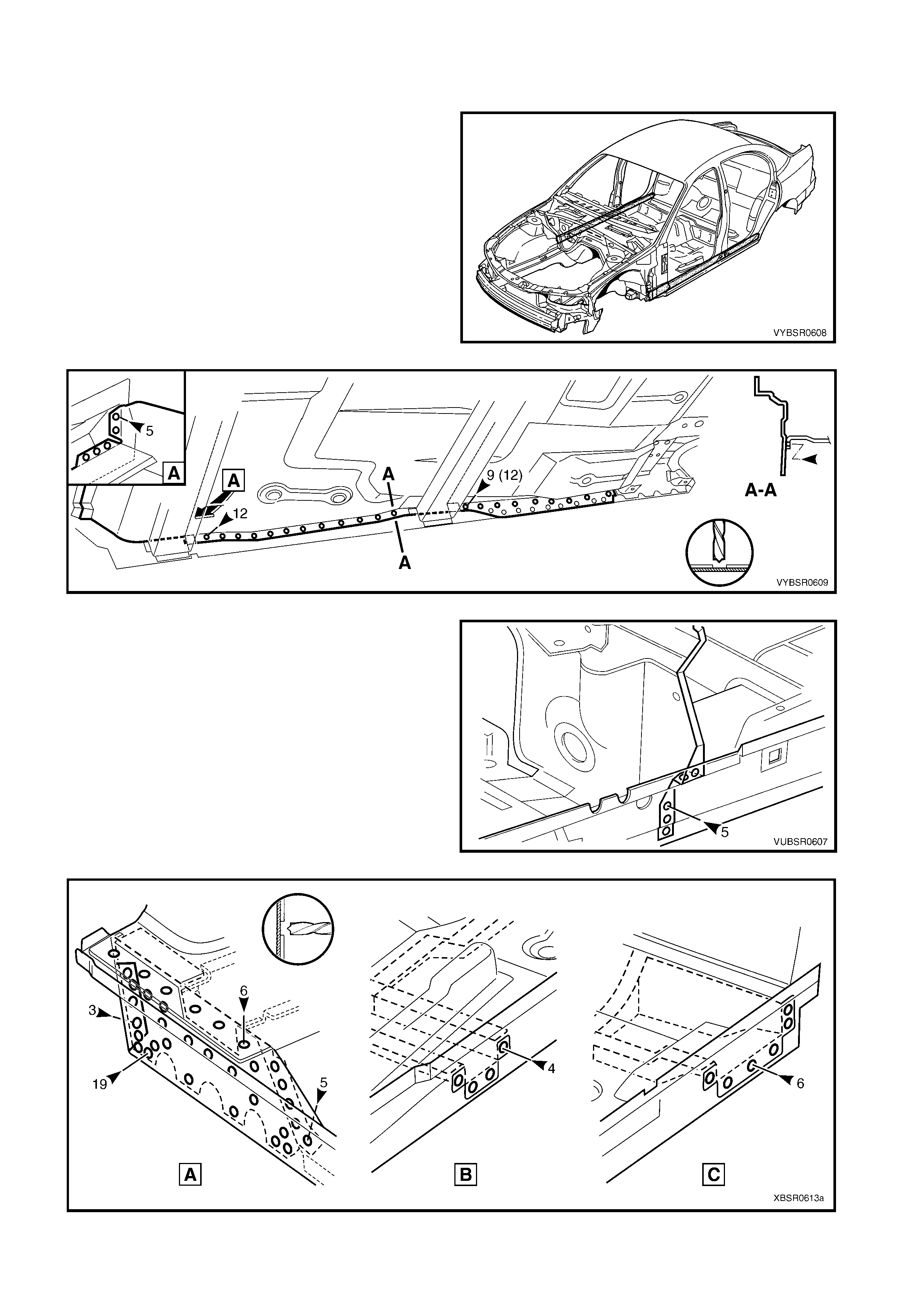
5. Using a scraper and heat gun, remove the body
sealer and deadener from the front floor and floor
extension attaching areas.
Figure 6-12
6. Mark the front floor panel extension for cutting as
shown. Cut the panel 30 mm inboard from the
front side rail flange.
7. Spot cut the welds attaching the partial front floor
panel extension to the front side rail assembly,
front wheelhouse panel assembly and front floor
panel assembly.
Figure 6-13
8. Spot cut the welds attaching the front floor panel
extension (1) to the hinge pillar inner panel (2)
from the direction shown A.
9. Remove the partial front floor panel extension and
repair any damage to adjacent panels as required.
10. Check and rectify the alignment of the body as
required, refer to 3. BODY DIMENSIONS in
Section 3A (Sedan), 3B (Wagon), 3C (Utility) or
3D (Coupe).
Figure 6-14
REPLACE
NOTE 1: Spot welding is the preferred method for attaching of panels and should be used whenever possible.
Where the spot welding equipment available will not access the required weld position, a plug weld should be
performed.
NOTE 2: The s ame number and pos ition of spot welds ( or plug welds) s hould be used when replac ing the panel,
as was used during manufacture, in order to maintain the original structural strength of the vehicle.
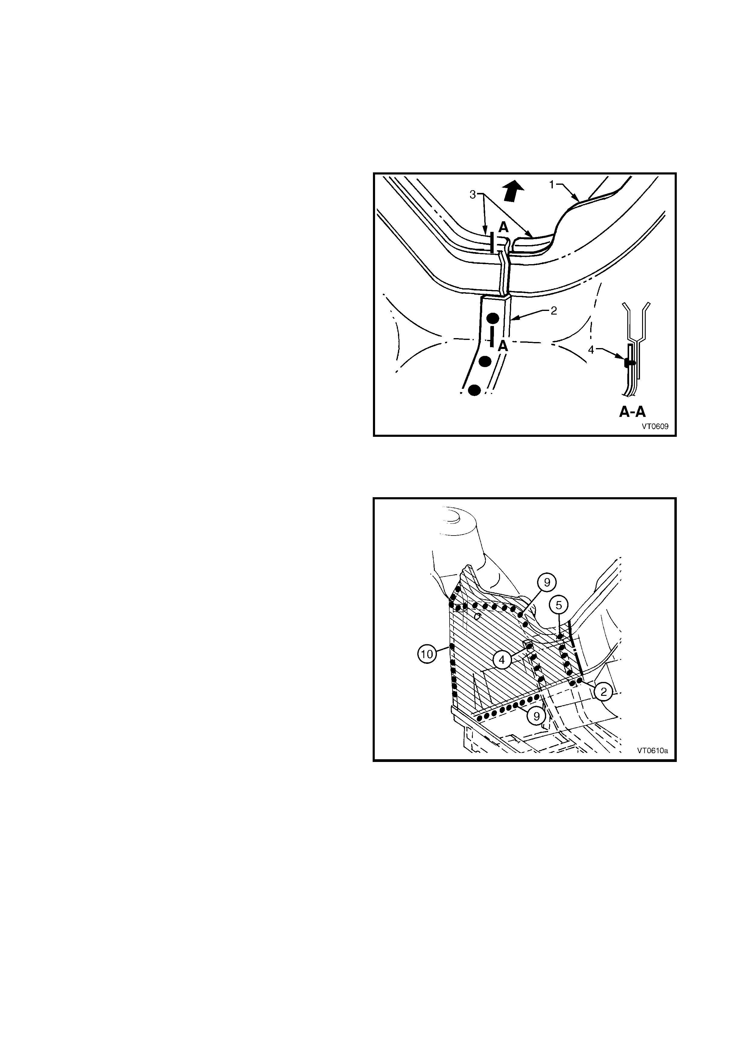
1. Accurately cut the required section from a new panel, allowing approximately 15 mm overlap for the lap joint.
2. On the new section, trim the glue track back 15
mm to allow butting against the section on the
vehicle.
3. Flange the new section of front floor panel
extension (1) using a suitable tool to form a
joggle (2) to facilitate the lap joint. The joggle
should be towards the interior of the vehicle.
4. Ensure that the old and new glue tracks (3) align,
to allow installation of the dash panel assembly.
The glue tracks need not be butt welded.
5. As required, mark the new panel with drilling
locations in prepar ation f or plug welding. Drill holes
as required.
6. Prepare all mating surfaces and treat with Weld
Through Primer (Item 1) as required, refer to
5. BODY SEALING, ADHESIVES & DEADENERS
in Section 3A (Sedan), 3B (Wagon), 3C (Utility)
or 3D (Coupe).
7. Spot or plug weld (4) the lap joint at a minimum
spacing of 35 mm along the join, then MIG weld
along the engine compartment side of the panels.
Figure 6-15
8. Spot or plug weld the partial floor panel extension
to the front side rails, front wheelhouse panel
assembly and front floor panel.
Figure 6-16
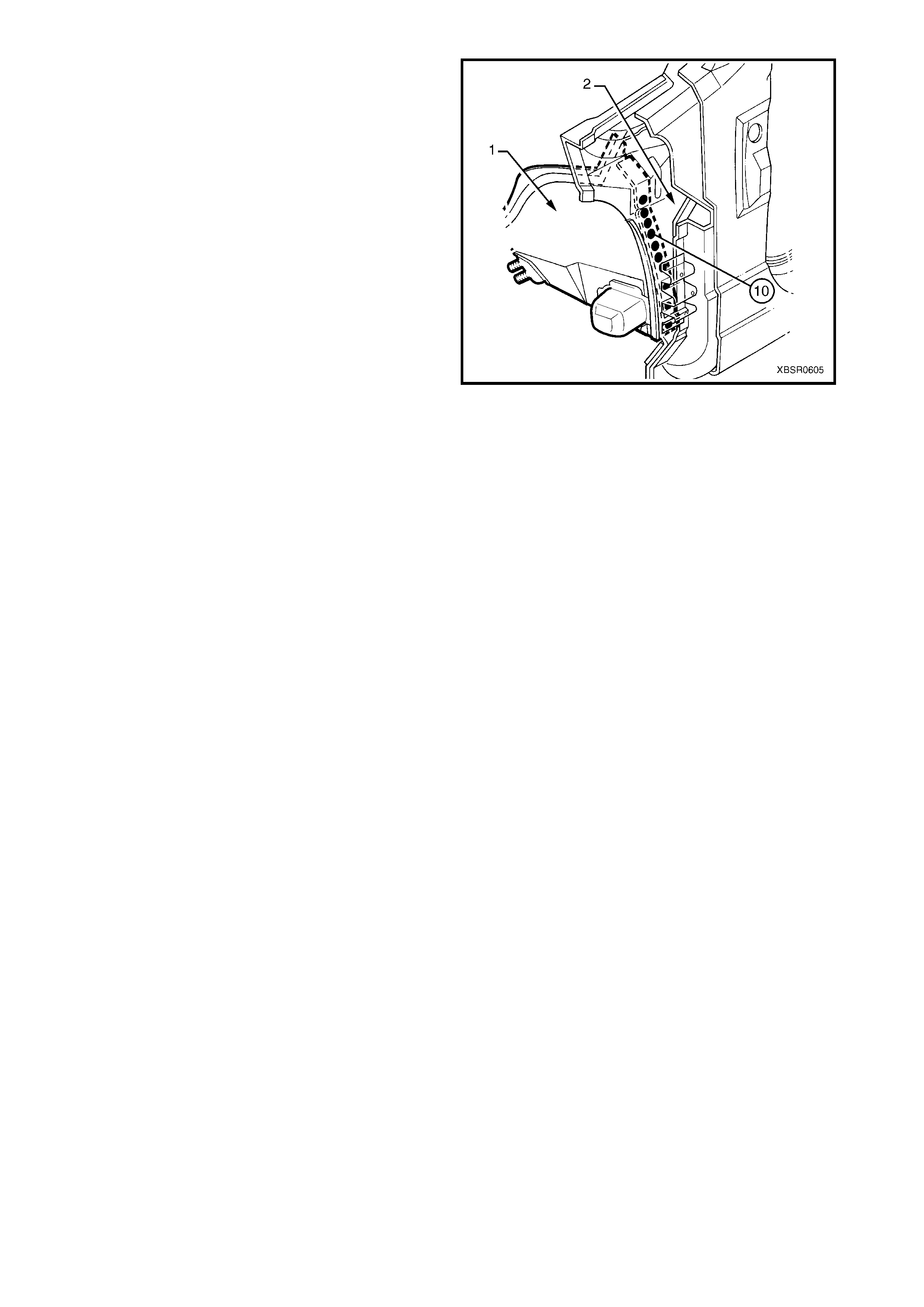
9. Spot or plug weld the front floor panel extension
(1) to the hinge pillar inner panel (2).
10. Replace any other removed panels as required,
refer to the relevant Section in this Supplement.
11. Refinish and paint panels and other components
as required. Refer to Section 3, 1.3 PAINT
REFINISHING.
12. Apply Joint Sealer (Item 3) as required. Refer to
5. BODY SEALING, ADHESIVES & DEADENERS
in Section 3A (Sedan), 3B (Wagon), 3C (Utility)
or 3D (Coupe).
13. Apply Cavity Wax (Item 8) as required to
the inside of any box sections or areas
inaccessible to paint, refer 6. CAVITY WAX in
Section 3A (Sedan), 3B (Wagon), 3C (Utility) or
3D (Coupe).
14. Apply floor deadeners as required, refer to
5. BODY SEALING, ADHESIVES & DEADENERS
in Section 3A (Sedan), 3B (Wagon), 3C (Utility)
or 3D (Coupe).
15. Replace the dash panel assembly, refer to
Section 5 COCKPIT MODULE.
16. Reinstall the remaining bolt-on panels and
components as required, refer to the appropriate
Section of the MY 2003 VY & V2 II Series Service
Information.
Figure 6-17
2.3 FRONT FLOOR PANEL ASSEMBLY – REPLACE
REMOVE
CAUTION: Care must be taken to avoid cutting the
fuel, brake or emission control pipes.
1. Remove the adjacent bolt-on panels and
components as described in the appropriate
Section of the MY 2003 VY & V2 Series II Service
Information.
2. Remove the adjoining panels as required, refer to
the relevant Section in this Supplement.
3. Secure the vehicle on a suitable fixture. As a
minimum, support the structural sections of the
vehicle on safety stands.
4. Using a scraper and heat gun, remove the body
sealer and deadener from the front floor attaching
areas.
5. For Utility vehicles, spot cut the welds attaching
the front floor rear extension to the front floor panel
assembly, refer to 3.4 FRONT FLOOR REAR
EXTENSION.
Figure 6-18
6. Spot cut the welds attaching the front floor panel extension to the front floor panel assembly, refer to
2.1 FRONT FLOOR PANEL EXTENSION – REPLACE.
7. From underneath the vehicle, s pot cut the welds attaching the front f loor panel assem bly to the inner rocker
panel assembly, refer to Figure 6-19.
NOTE: Sedan / Coupe (Wagon / Utility)
Figure 6-19
8. From underneath the vehicle, spot cut the welds
attaching the park brake cable bracket to the rear
floor panel assembly.
9. On each side of the vehicle, spot cut the welds
attaching the fr ont f loor panel as s embly to the front
side rail assemblies, refer to Figure 6-21.
Figure 6-20
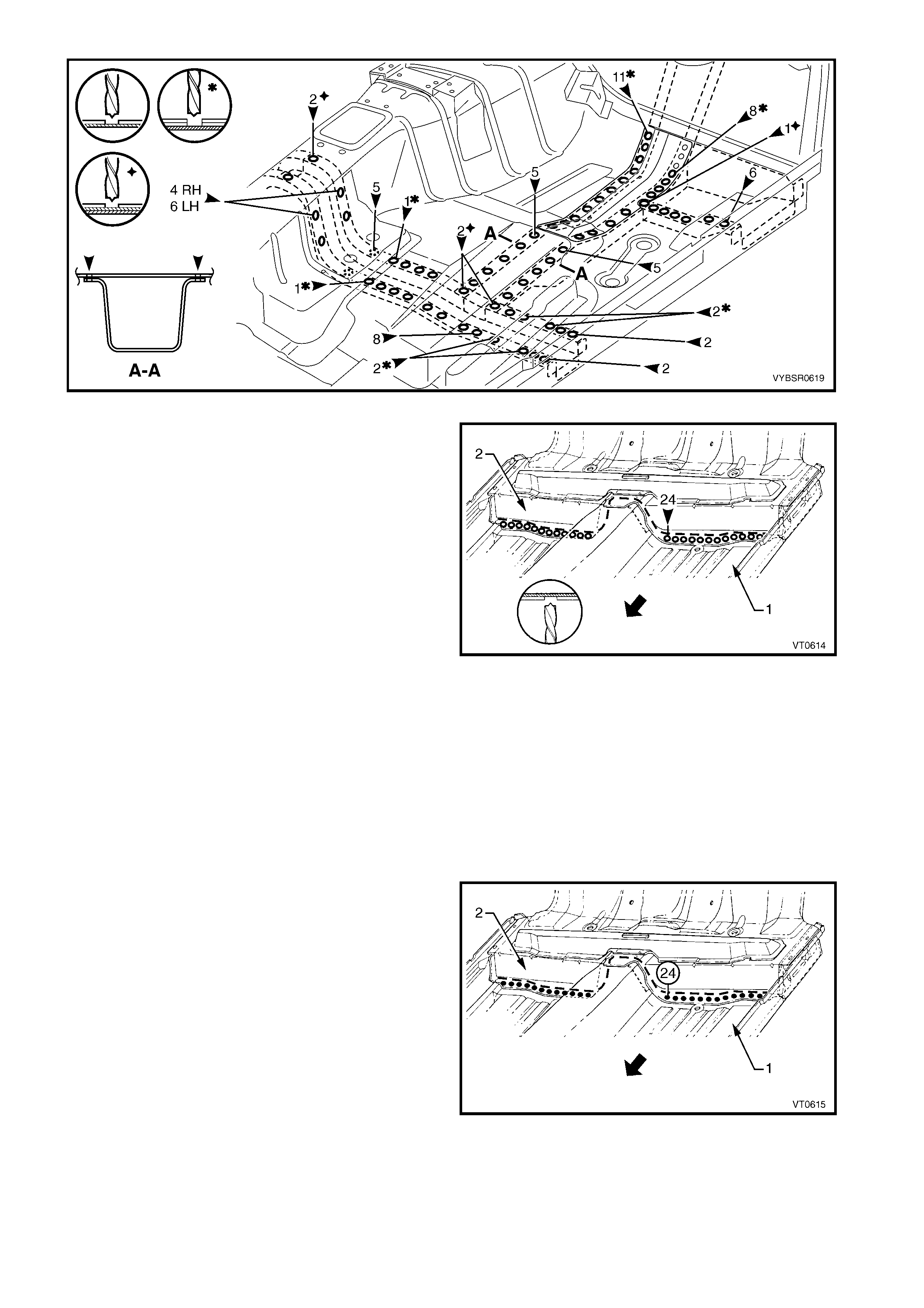
Figure 6-21
10. Spot cut the welds attaching the front floor panel
assembly (1) to the rear floor panel assembly (2).
11. Remove the front floor assembly from the vehicle
and repair any damage to adjacent panels as
required.
12. Check and rectify the alignment of the body as
required, refer to 3. BODY DIMENSIONS in
Section 3A (Sedan), 3B (Wagon), 3C (Utility) or
3D (Coupe).
Figure 6-22
REPLACE
NOTE 1: Spot welding is the preferred method for attaching of panels and should be used whenever possible.
Where the spot welding equipment available will not access the required weld position, a plug weld should be
performed.
NOTE 2: The s ame number and pos ition of spot welds ( or plug welds) s hould be used when replacing the panel,
as was used during manufacture, in order to maintain the original structural strength of the vehicle.
1. As required, mark the new panel with drilling locations in preparation for plug welding. Drill holes as required.
2. Prepare all mating surfaces and treat with Weld Through Primer (Item 1) as required, refer to 5. BODY
SEALING, ADHESIVES & DEADENERS in Section 3A (Sedan), 3B (Wagon), 3C (Utility) or 3D (Coupe).
3. Secure the front floor panel assembly (1) in
position and make several tack welds around its
circumference. Plug weld to the rear floor panel
assembly (2).
4. F rom under neath the vehicle, s pot or plug weld the
front floor assembly to the inner rocker panel
assembly, 14 places forward of the crossmember
and 20 places for Sedan and Coupe or 24 places
for Wagon and Utility rear of the crossmember.
From inside the vehicle, also spot weld 5 places.
Refer to Figure 6-24.
Figure 6-23
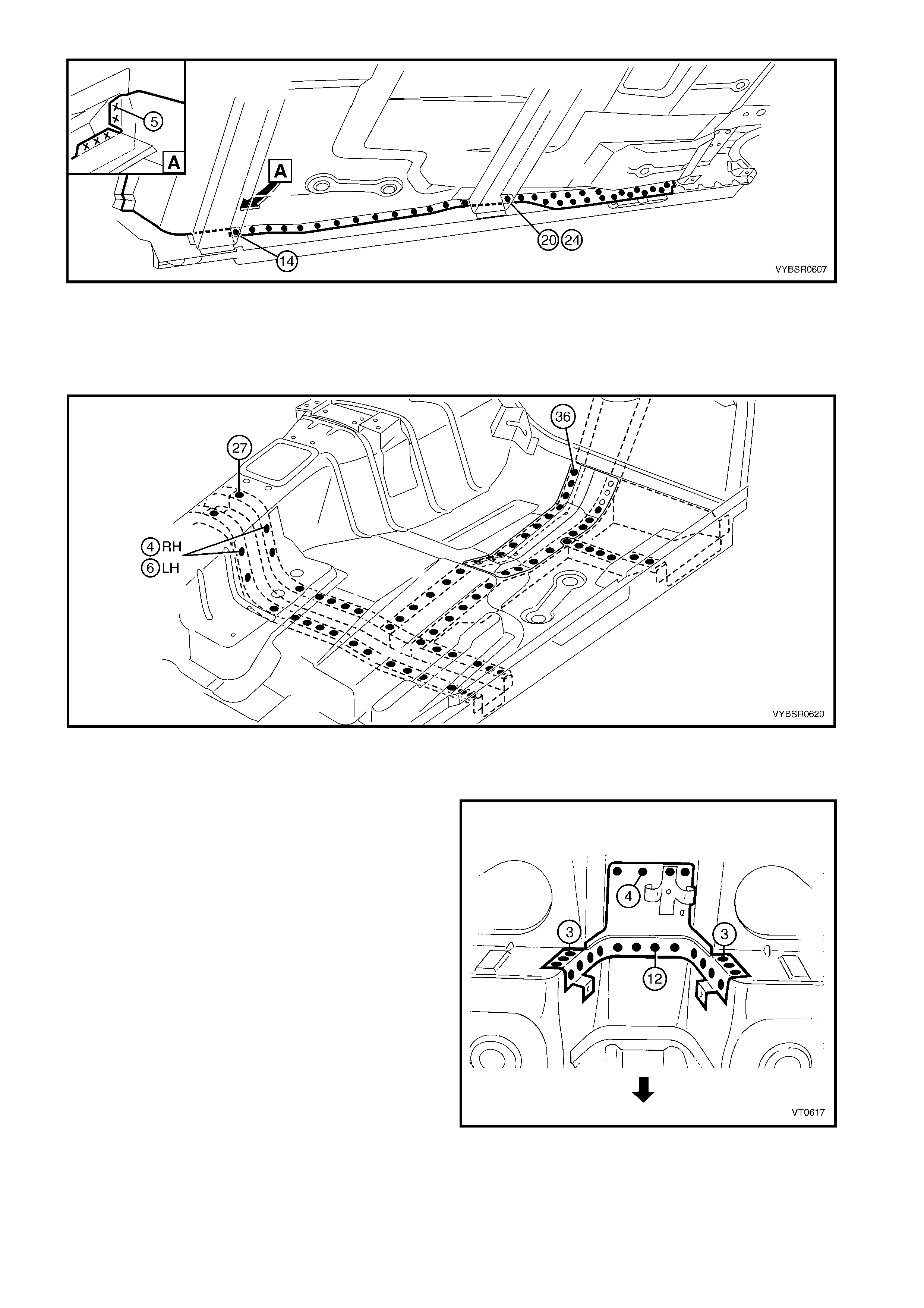
Figure 6-24
6. Replace the front floor panel extension, or weld the extension to the front floor panel assembly, refer to
2.1 FRONT FLOOR PANEL EXTENSION – REPLACE.
7. On each side of the vehicle, plug weld the front floor panel assembly to the front side rail assemblies, refer to
Figure 6-25.
Figure 6-25
8. For Utility vehicles, plug weld the front floor rear extension to the front floor panel assembly, refer to
3.4 FRONT FLOOR REAR EXTENSION.
9. Reinstall the park brake cable bracket to the rear
floor panel assembly.
10. Replace any other removed panels as required,
refer to the relevant Section in this Supplement.
11. Refinish and paint panels and other components
as required. Refer to Section 3, 1.3 PAINT
REFINISHING.
12. Apply Joint Sealer (Item 3) as required. Refer to
5. BODY SEALING, ADHESIVES & DEADENERS
in Section 3A (Sedan), 3B (Wagon), 3C (Utility)
or 3D (Coupe).
13. Apply Cavity Wax (Item 8) as required to the
inside of any box sections or areas inacces sible to
paint, refer to 6. CAVITY WAX in Section
3A (Sedan), 3B (Wagon), 3C (Utility) or
3D (Coupe).
Figure 6-26

14. Apply floor deadeners as required, refer to 5. BODY SEALING, ADHESIVES & DEADENERS in Section
3A (Sedan), 3B (Wagon), 3C (Utility) or 3D (Coupe).
15. Apply Spray-on deadener (Item 7) as required to the underside of the floor, refer to 5. BODY SEALING,
ADHESIVES & DEADENERS in Section 3A (Sedan), 3B (Wagon), 3C (Utility) or 3D (Coupe).
16. For all vehicles exc ept Utility, apply fusible reinf orc em ent patches, r efer to 5.7 FUSIBLE REINFO RCEMENT
PATCHES in Section 3A (Sedan), 3B (Wagon) or 3D (Coupe).
17. Reinstall the remaining bolt-on panels and components as required, refer to the appropriate Section of the
MY 2003 VY & V2 II Series Service Information.
2.4 INNER ROCKER PANEL ASSEMBLY – REPLACE
REMOVE
1. Remove the adjacent bolt-on panels and
components as described in the appropriate
Section of the MY 2003 VY & V2 Series II Service
Information.
2. Secure the vehicle on a suitable fixture. As a
minimum, support the structural sections of the
vehicle on safety stands.
3. Remove the adjacent panels as required, refer to
the relevant Section in this Supplement.
4. Spot cut the welds attaching the front floor panel
assembly to the inner rocker panel as required.
Refer to Figure 6-28.
NOTE: Sedan / Coupe (Wagon / Utility)
Figure 6-27
Figure 6-28
5. For Utility vehicles, spot cut the welds attaching
the inner rocker panel assembly to the front floor
rear extension assembly.
6. Spot cut the welds attac hing the inner rocker panel
assembly to the rear floor panel outer extension
(A), centre crossm ember (B), and front floor panel
support (C), refer to Figure 6-30.
Figure 6-29
Figure 6-30
7. Remove the two MIG welds (1) attac hing the inner
rocker panel to the hinge pillar inner assembly.
8. If not alr eady done so, remove the f our spot welds,
or for some models four MIG welds (2), attaching
the inner rocker panel to the hinge pillar inner
assembly and rocker panel reinforcement.
9. Remove the inner rocker panel from the vehicle
and repair any damage to adjacent panels as
required.
10. Check and rectify the alignment of the body as
required, refer to 3. BODY DIMENSIONS in
Section 3A (Sedan), 3B (Wagon), 3C (Utility) or
3D (Coupe). Figure 6-31
REPLACE
NOTE 1: Spot welding is the preferred method for attaching of panels and should be used whenever possible.
Where the spot welding equipment available will not access the required weld position, a plug weld should be
performed.
NOTE 2: The s ame number and pos ition of spot welds ( or plug welds) s hould be used when replacing the panel,
as was used during manufacture, in order to maintain the original structural strength of the vehicle.
1. As required, mark the new panel with drilling locations in preparation for plug welding. Drill holes as required.
2. Prepare all mating surfaces and treat with Weld Through Primer (Item 1) as required, refer to 5. BODY
SEALING, ADHESIVES & DEADENERS in Section 3A (Sedan), 3B (Wagon), 3C (Utility) or 3D (Coupe).
3. Clamp the inner rocker panel in position, noting to ensure it fits behind the hinge pillar inner assembly.
4. Make two MIG welds (1) and if rem oved, four MIG
welds (2), to attach inner rocker panel to the hinge
pillar inner assembly.
NOTE: If r em oved, the four plug welds ar e to be m ade
once the door opening frame assembly is installed.
5. Plug weld the inner rocker panel to the rear floor
panel outer ex tension ( A), c entr e cr os smember (B)
and front floor panel support (C), refer Figure 6-33.
Figure 6-32
Figure 6-33
6. Spot or plug weld the front floor panel assembly to the inner rocker panel, underneath and inside. Refer to
Figure 6-34.
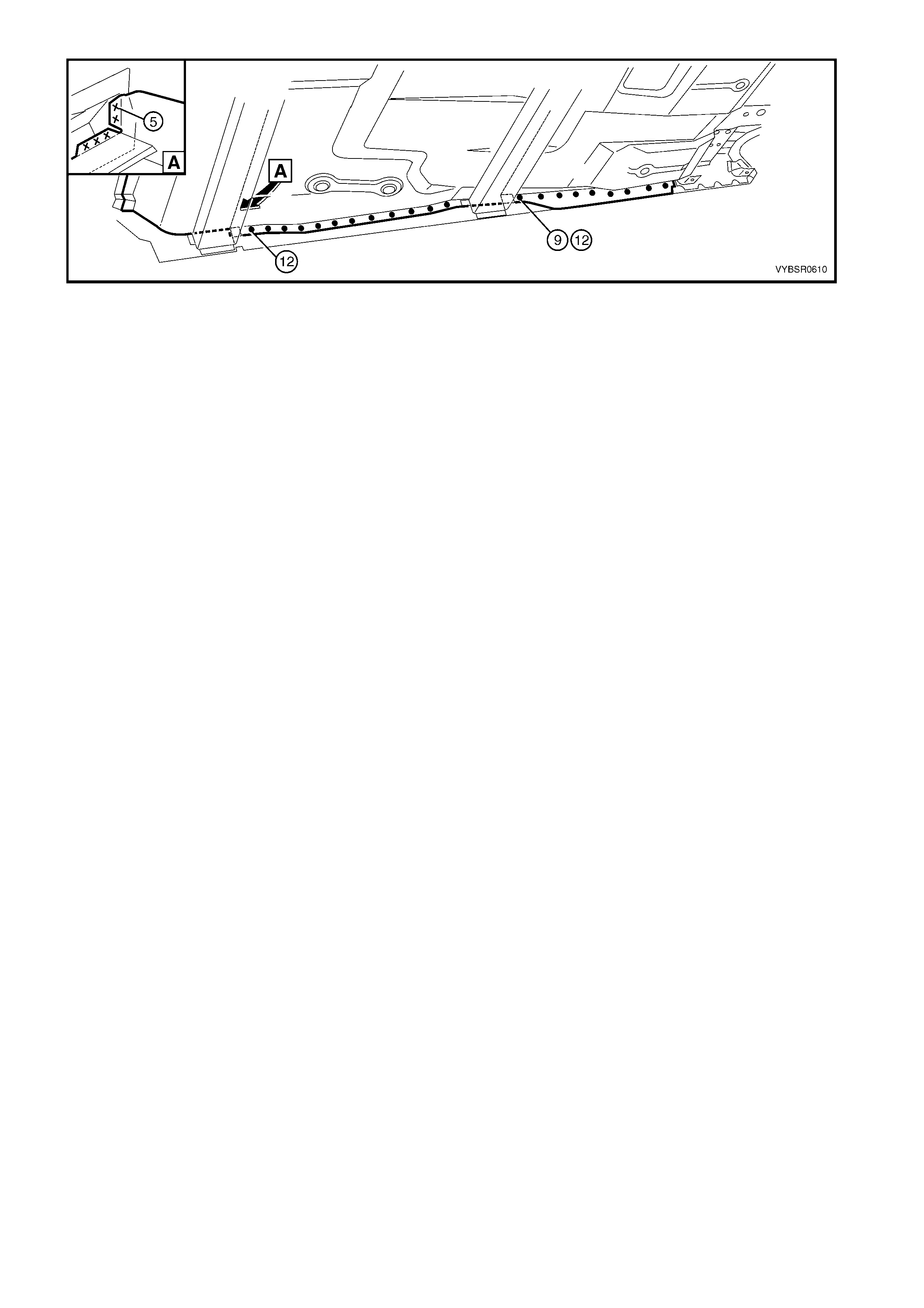
Figure 6-34
7. Replace the adjoining removed panels as required, refer to the relevant Section in this Supplement.
8. Refinish and paint panels and other components as required. Refer to Section 3, 1.3 PAINT REFINISHING.
9. Apply Joint Sealer (Item 3) as required. Refer to 5. BODY SEALING, ADHESIVES & DEADENERS in
Section 3A (Sedan), 3B (Wagon), 3C (Utility) or 3D (Coupe).
10. Apply Cavity W ax (Item 8) as required to the ins ide of any box s ections or areas inac cessible to paint, ref er
to 6. CAVITY WAX in Section 3A (Sedan), 3B (Wagon), 3C (Utility ) or 3D (Coupe).
11. Reinstall the remaining bolt-on panels and components as required, refer to the appropriate Section of the
MY 2003 VY & V2 II Series Service Information.
2.5 TRANSMISSION SUPPORT BRACKET – REPLACE
REMOVE
1. Remove the adjacent bolt-on panels and components as described in the appropriate Section of the
MY 2003 VY & V2 Series II Service Information.
2. Using a scraper and heat gun, remove the body sealer and deadener from the front floor attaching areas.
3. Spot cut the 18 welds for the right-hand side or 23 welds for the left-hand side attaching the transmission
support bracket to the front floor panel assembly as required. Refer to Figure 6-35.
4. Remove the transmission support bracket from the vehicle and repair any damage to the adjacent area as
required.
Figure 6-35
REPLACE
NOTE 1: Spot welding is the preferred method for attaching of panels and should be used whenever possible.
Where the spot welding equipment available will not access the required weld position, a plug weld should be
performed.
NOTE 2: The s ame number and pos ition of spot welds ( or plug welds) s hould be used when replacing the panel,
as was used during manufacture, in order to maintain the original structural strength of the vehicle.
1. As required, mark the new panel with drilling locations in preparation for plug welding. Drill holes as required.
2. Prepare all mating surfaces and treat with Weld Through Primer (Item 1) as required, refer to 5. BODY
SEALING, ADHESIVES & DEADENERS in Section 3A (Sedan), 3B (Wagon), 3C (Utility) or 3D (Coupe).
NOTE: Positioning of the transmission support bracket is critical to driveline orientation. Incorrect location can
cause driveline vibrations.
3. Position the transmission support bracket so that the rear tooling hole centre is 190 mm from the vehicle
centre and 225 mm rearward of the datum hole centres in the floor, refer to Figure 6-36.
4. Temporarily bolt the transmission crossmember in position to help locate the mount. Check the
crossmember for correct orientation to the vehicle.
5. Clamp or tack weld the mount in position and recheck positioning.
6. Spot or plug weld the m ount ass em bly to the floor, 18 places for the right-hand side or 22 places f or the left-
hand side, refer to Figure 6-36.
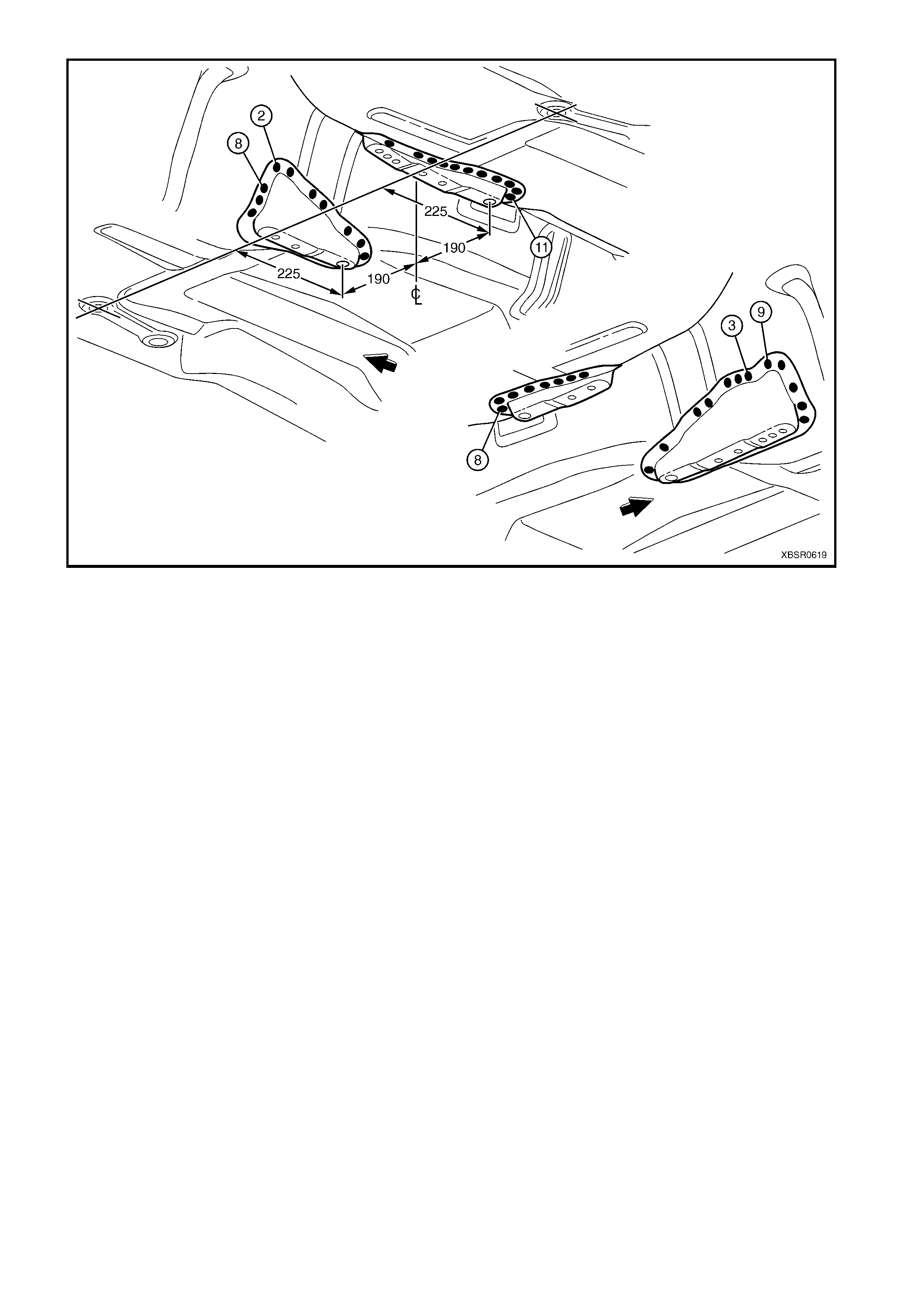
Figure 6-36
7. Refinish and paint panels and other components as required. Refer to Section 3, 1.3 PAINT REFINISHING.
8. Apply Joint Sealer (Item 3) as required. Refer to 5. BODY SEALING, ADHESIVES & DEADENERS in
Section 3A (Sedan), 3B (Wagon), 3C (Utility) or 3D (Coupe).
9. Apply Cavity W ax (Item 8) as required to the inside of any box sections or areas inac cessible to paint, ref er
to 6. CAVITY WAX in Section 3A (Sedan), 3B (Wagon), 3C (Utility ) or 3D (Coupe).
10. Apply floor deadeners as required, refer to 5. BODY SEALING, ADHESIVES & DEADENERS in Section
3A (Sedan), 3B (Wagon), 3C (Utility) or 3D (Coupe).
11. Apply Spray-on deadener (Item 7) as required to the underside of the floor, refer to 5. BODY SEALING,
ADHESIVES & DEADENERS in Section 3A (Sedan), 3B (Wagon), 3C (Utility) or 3D (Coupe).
12. Reinstall the remaining bolt-on panels and components as required, refer to the appropriate Section of the
MY 2003 VY & V2 II Series Service Information.
2.6 SEAT INNER BRACKET ASSEMBLY – REPLACE
REMOVE
1. Remove the adjacent bolt-on panels and components as described in the appropriate Section of the
MY 2003 VY & V2 Series II Service Information.
2. As required, use a scraper and heat gun to remove the body sealer and deadener from the front floor and
floor extension attaching areas.
3. Lower the transmission rear mount and propeller shaft centre bearing assembly to avoid damage from heat.
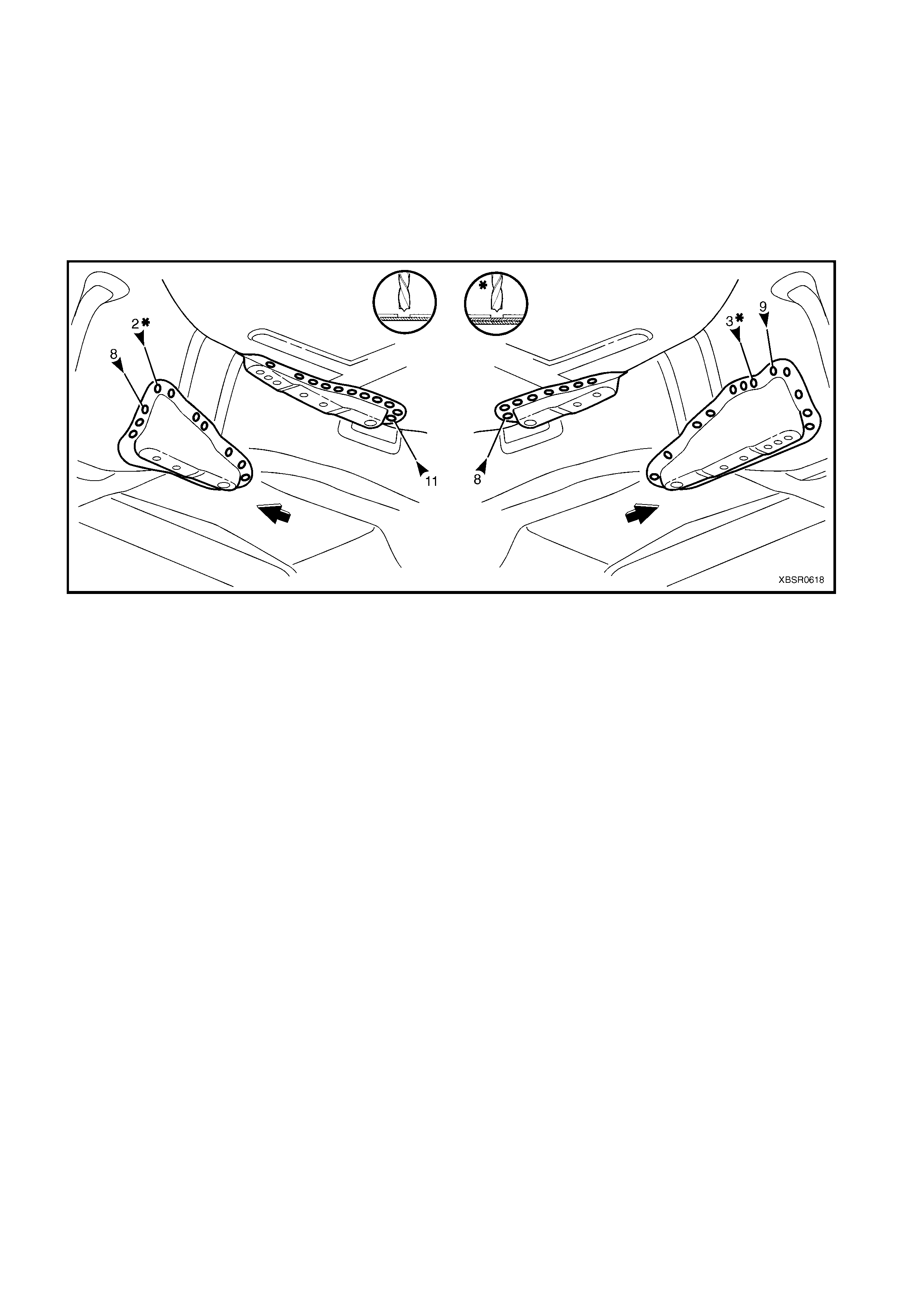
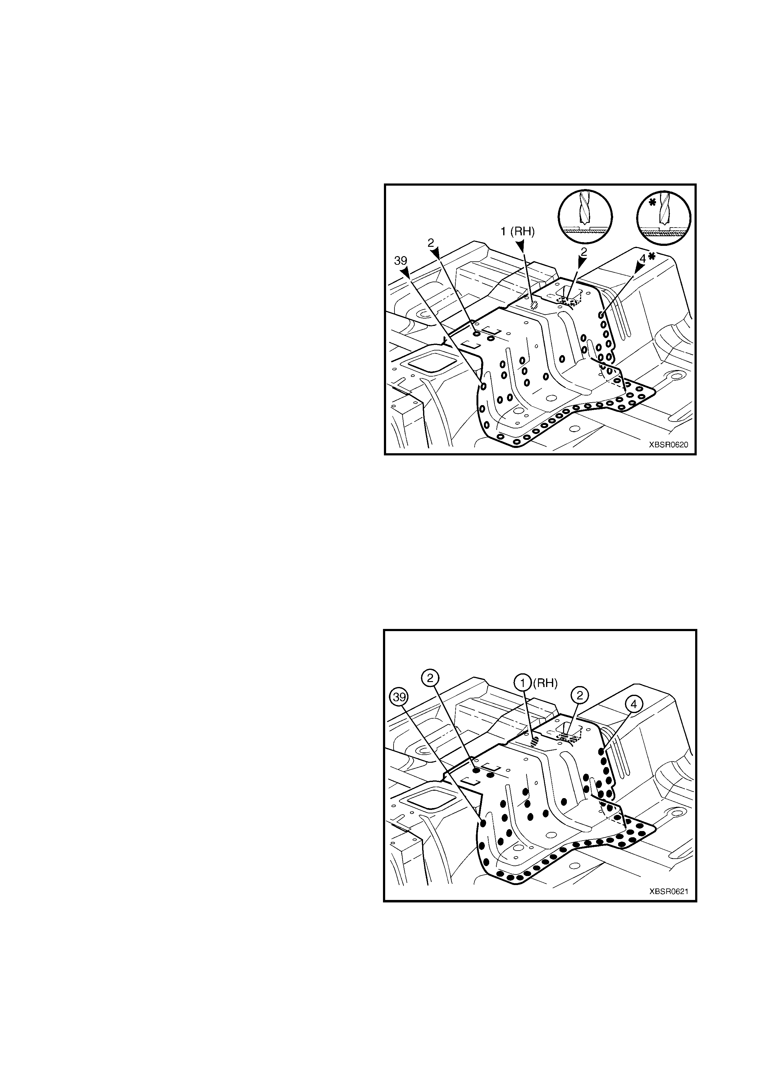
4. Spot cut the 39 welds each side attac hing the seat
inner bracket assembly to the floor.
5. Spot cut the four welds each side attaching the
bracket assembly to the floor and propeller shaft
hanger assembly.
6. Spot cut the two welds front and rear attaching the
top of the bracket assembly to the floor.
7. Spot cut the weld attaching the right-hand side of
the bracket assembly to the floor.
8. Remove the bracket assembly from the vehicle
and repair any damage to the adjacent area as
required.
Figure 6-37
REPLACE
NOTE 1: Spot welding is the preferred method for attaching of panels and should be used whenever possible.
Where the spot welding equipment available will not access the required weld position, a plug weld should be
performed.
NOTE 2: The s ame number and pos ition of spot welds ( or plug welds) s hould be used when replacing the panel,
as was used during manufacture, in order to maintain the original structural strength of the vehicle.
1. As required, mark the new panel with drilling locations in preparation for plug welding. Drill holes as required.
2. Prepare all mating surfaces and treat with Weld Through Primer (Item 1) as required, refer to 5. BODY
SEALING, ADHESIVES & DEADENERS in Section 3A (Sedan), 3B (Wagon), 3C (Utility) or 3D (Coupe).
3. Install the seat inner bracket assembly in position
and chec k that the seat m ount holes will align with
the seat.
4. Spot or plug weld the br ac ket assembly to the floor
(and propeller shaft hanger assembly if required)
as shown.
5. Refinish and paint panels and other components
as required. Refer to Section 3, 1.3 PAINT
REFINISHING.
6. Apply floor deadeners as required, refer to 5.
BODY SEALING, ADHESIVES & DEADENERS in
Section 3A (Sedan), 3B (Wagon), 3C (Utility) or
3D (Coupe).
7. Reinstall the transmission rear mount, refer to
appropriate section in the MY 2003 VY & V2
Series II Service Information.
8. Reinstall the propeller shaft centre bearing
assembly, refer to Section 4C, PROPELLER
SHAFT AND UNIVERSAL JOINT in the MY 2003
VY & V2 Series II Service Information.
9. Reinstall the remaining bolt-on panels and
components as required, refer to the appropriate
Section of the MY 2003 VY & V2 II Series Service
Information.
Figure 6-38
2.7 SEAT OUTER BRACKET ASSEMBLY – REPLACE
REMOVE
1. Remove the adjacent bolt-on panels and components as described in the appropriate Section of the
MY 2003 VY & V2 Series II Service Information.
2. Using a scraper and heat gun, remove the body sealer and deadener from the front floor attaching areas.
3. From the underside of the floor, remove deadener in the area of the reinforcement.
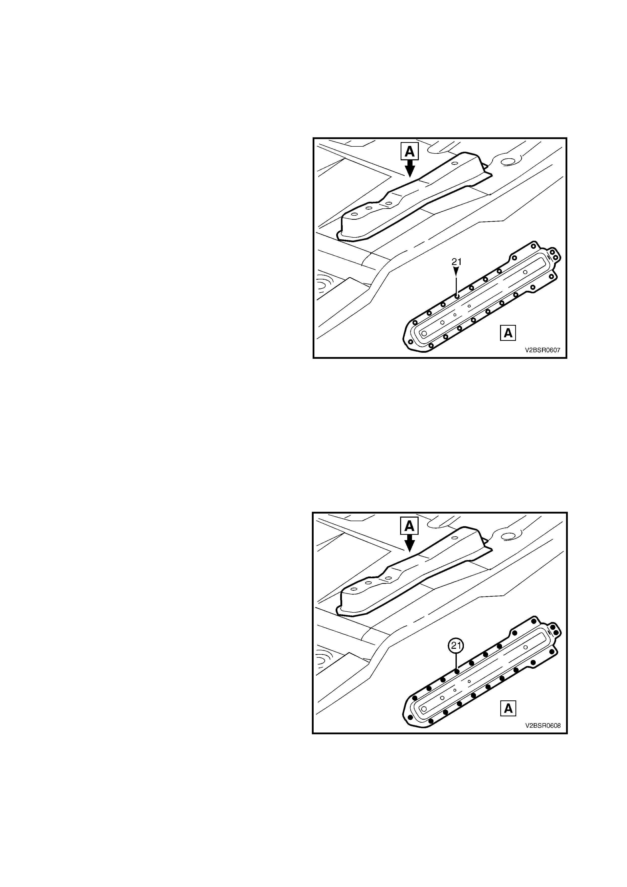
4. Spot cut the 21 welds attaching the seat outer
bracket assembly to the floor.
5. Remove the bracket assembly from the vehicle
and repair any damage to the adjacent area as
required.
Figure 6-39
REPLACE
NOTE 1: Spot welding is the preferred method for attaching of panels and should be used whenever possible.
Where the spot welding equipment available will not access the required weld position, a plug weld should be
performed.
NOTE 2: The s ame number and pos ition of spot welds ( or plug welds) s hould be used when replacing the panel,
as was used during manufacture, in order to maintain the original structural strength of the vehicle.
1. As required, mark the new panel with drilling locations in preparation for plug welding. Drill holes as required.
2. Prepare all mating surfaces and treat with Weld Through Primer (Item 1) as required, refer to 5. BODY
SEALING, ADHESIVES & DEADENERS in Section 3A (Sedan), 3B (Wagon), 3C (Utility) or 3D (Coupe).
3. Install the seat outer bracket assembly in position
and chec k that the seat m ount holes will align with
the seat.
4. Spot or plug weld the bracket assembly to the
floor, 21 places as shown.
5. Refinish and paint panels and other components
as required. Refer to Section 3, 1.3 PAINT
REFINISHING.
6. Apply Spray-on deadener (Item 7) as required to
the underside of the floor, refer to 5. BODY
SEALING, ADHESIVES & DEADENERS in
Section 3A (Sedan), 3B (Wagon), 3C (Utility) or
3D (Coupe).
7. Apply floor deadeners as required, refer to 5.
BODY SEALING, ADHESIVES & DEADENERS in
Section 3A (Sedan), 3B (Wagon), 3C (Utility) or
3D (Coupe).
8. Reinstall the remaining bolt-on panels and
components as required, refer to the appropriate
Section of the MY 2003 VY & V2 II Series Service
Information.
Figure 6-40
2.8 PROPELLER SHAFT HANGER ASSEMBLY – REPLACE
REMOVE
1. Remove the adjacent bolt-on panels and components as described in the appropriate Section of the
MY 2003 VY & V2 Series II Service Information.
2. Remove the propeller shaft and centre bearing assembly, refer to Section 4C PROPELLER SHAFT AND
UNIVERSAL JOINT in the MY 2003 VY & V2 Series II Service Information.
3. Using a scraper and heat gun, remove the body sealer and deadener from the front floor attaching areas.
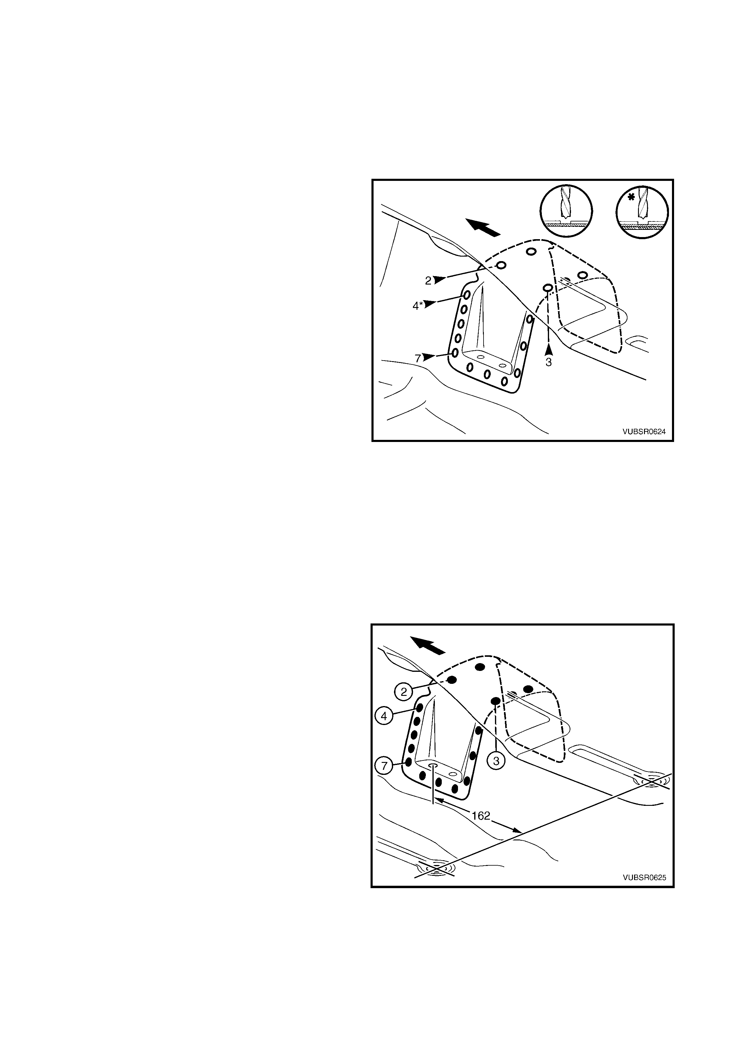
4. Spot cut the 2 welds front and 3 welds rear
attaching the propeller shaft hanger assembly to
the floor.
5. Spot cut the 7 welds each side attaching the
hanger assembly to the floor.
6. Spot cut the 4 welds each side attaching the
hanger assembly to the floor and seat inner
bracket assembly.
7. Remove the hanger assembly from the vehicle and
repair any damage to the adjacent area as
required.
Figure 6-41
REPLACE
NOTE 1: Spot welding is the preferred method for attaching of panels and should be used whenever possible.
Where the spot welding equipment available will not access the required weld position, a plug weld should be
performed.
NOTE 2: The s ame number and pos ition of spot welds ( or plug welds) s hould be used when replacing the panel,
as was used during manufacture, in order to maintain the original structural strength of the vehicle.
1. As required, mark the new panel with drilling locations in preparation for plug welding. Drill holes as required.
2. Prepare all mating surfaces and treat with Weld Through Primer (Item 1) as required, refer to 5. BODY
SEALING, ADHESIVES & DEADENERS in Section 3A (Sedan), 3B (Wagon), 3C (Utility) or 3D (Coupe).
3. Install the propeller shaft hanger assembly,
positioning each f ront datum hole 162 m m forward
of the datum hole centres in the floor.
4. Spot or plug weld the hanger ass embly to the floor,
two places front and three places rear.
5. Spot or plug weld the hanger ass embly to the floor,
seven places each side.
6. Spot or plug weld the hanger assem bly to the f loor
and seat inner brack et assem bly, four places each
side.
7. Refinish and paint panels and other components
as required. Refer to Section 3, 1.3 PAINT
REFINISHING.
8. Apply Spray-on deadener (Item 7) as required to
the underside of the floor, refer to 5. BODY
SEALING, ADHESIVES & DEADENERS in
Section 3A (Sedan), 3B (Wagon), 3C (Utility) or
3D (Coupe).
9. Apply floor deadeners as required, refer to
5. BODY SEALING, ADHESIVES & DEADENERS
in Section 3A (Sedan), 3B (Wagon), 3C (Utility)
or 3D (Coupe).
Figure 6-42

10. Install the propeller shaft and centre bearing assembly, refer to Section 4C PROPELLER SHAFT &
UNIVERSAL JOINTS in the MY 2003 VY & V2 Series II Service Information.
11. Reinstall the remaining bolt-on panels and components as required, refer to the appropriate Section of the
MY 2003 VY & V2 II Series Service Information.
3. SERVICE OPERATIONS – UTILITY SEATBACK ASSEMBLY
3.1 LOAD COMPARTMENT EXTENSION OUTER PANEL & BRACKET – REPLACE
REMOVE
1. Remove the adjacent bolt-on panels and
components as described in the appropriate
Section of the MY 2003 VY & V2 Series II Service
Information.
2. Remove the rear window, refer Section 1A6
STATIONARY WINDOWS in the MY 2003 VY &
V2 Series II Service Information
3. Remove the adjacent panels as required, refer to
the relevant Section in this Supplement.
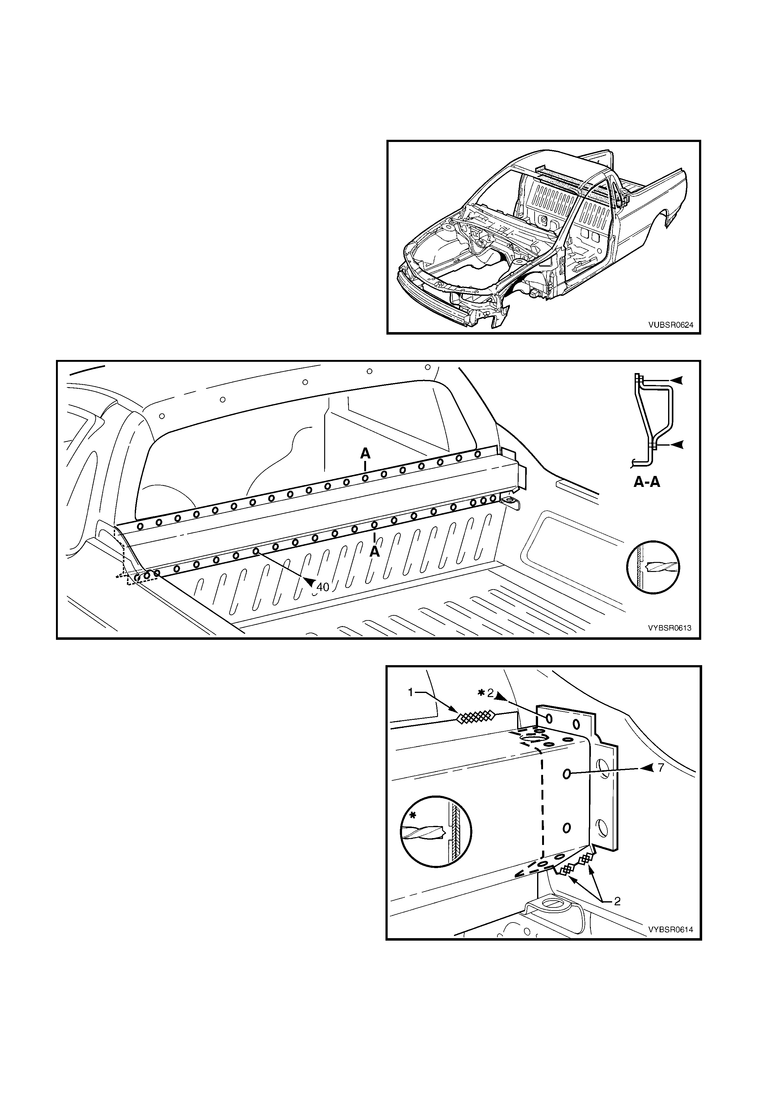
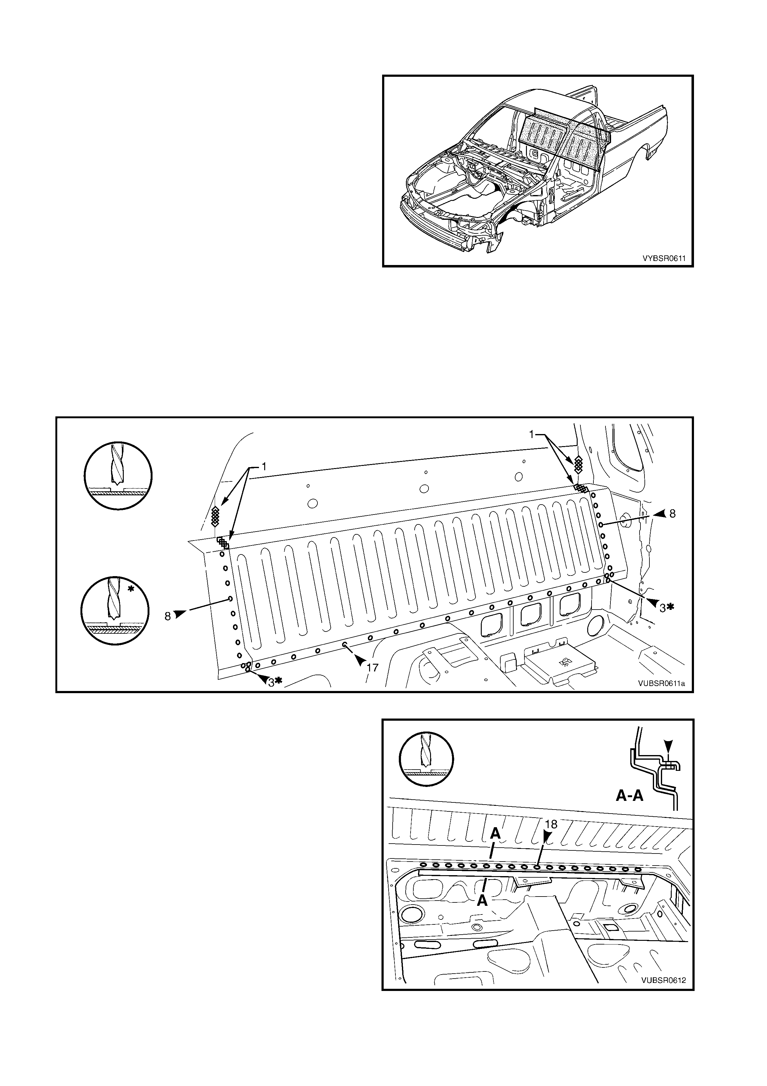
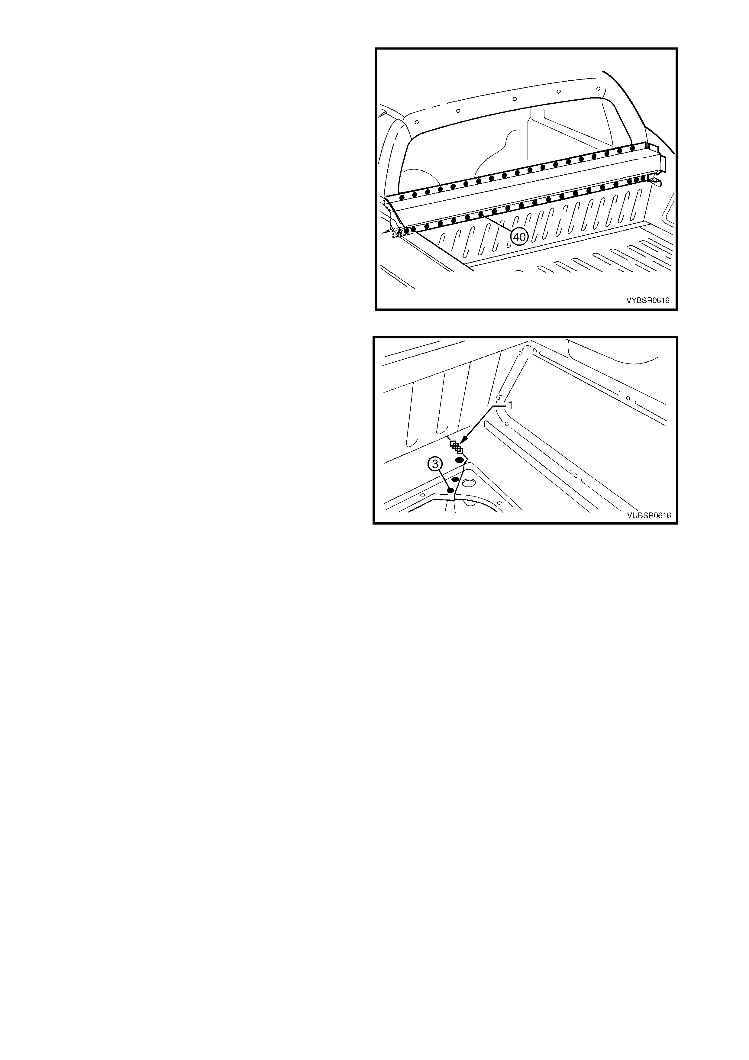
4. Spot cut the 40 welds attaching the load
compartment extension outer panel to the front
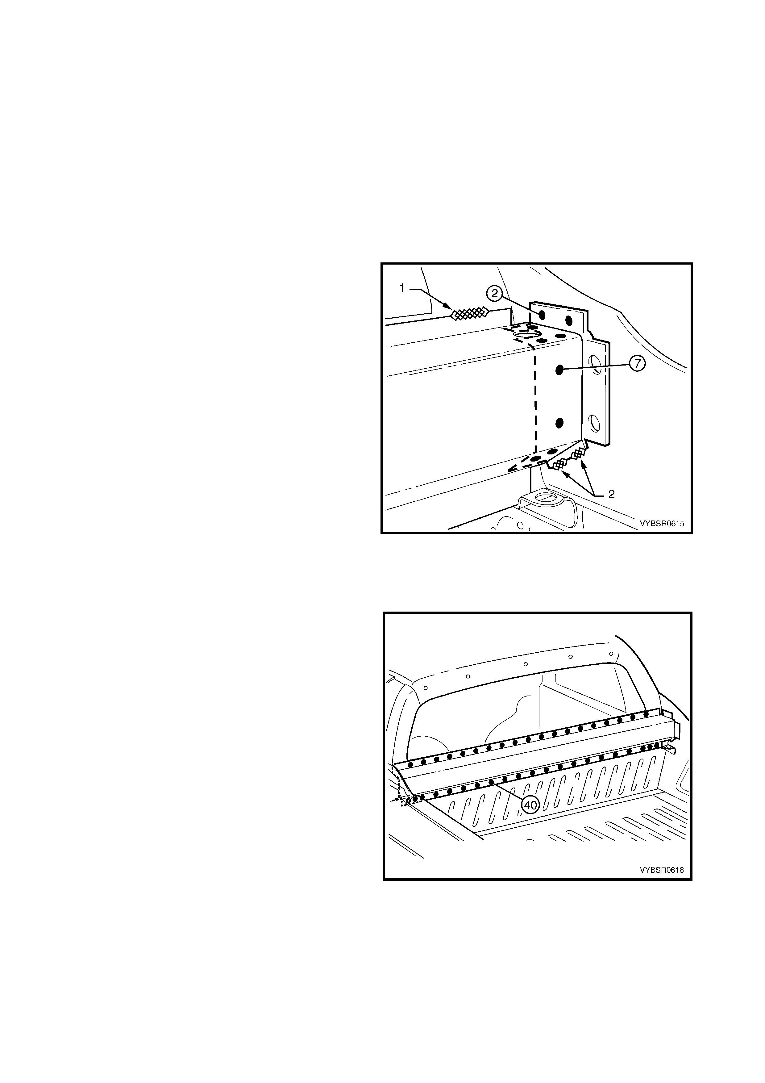
seat back panel, refer to Figure 6-44.
Figure 6-43
Figure 6-44
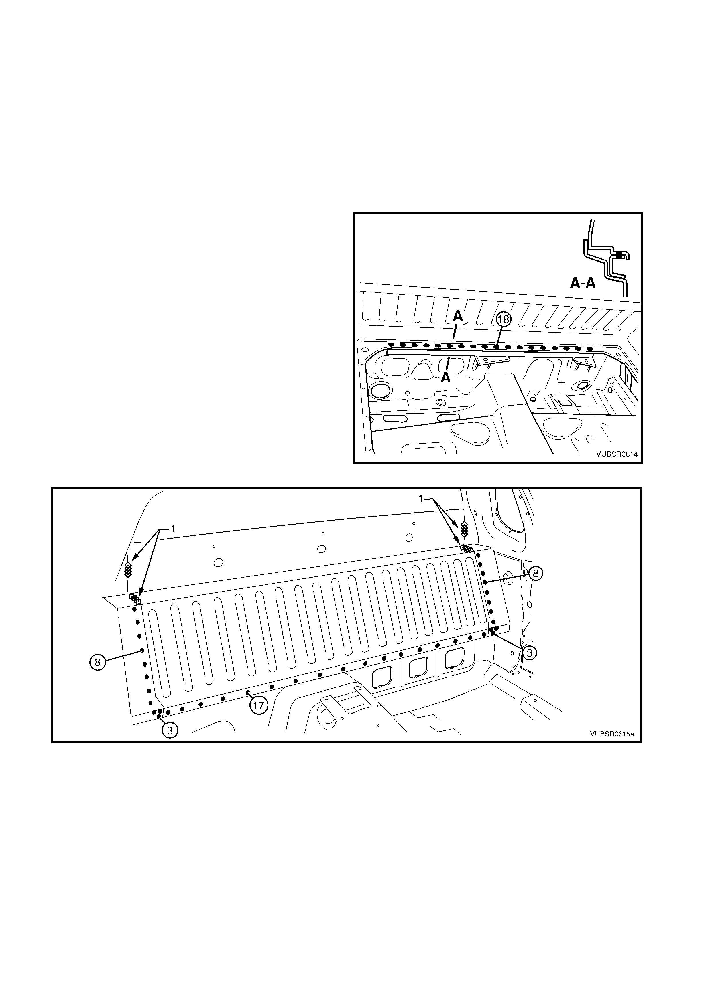
5. For the right-hand side either:
a. spot cut the two welds and grind off the three
MIG welds (1 & 2) attaching the load
compartment extension outer panel and load
compartment extension panel bracket, or
b. spot cut the seven welds attaching the load
com partm ent extension outer panel to the load
compartment extension panel bracket and
grind off the MIG weld (1).
6. For the left-hand side, spot cut the two welds and
grind off the three MIG welds attaching the load
compartment extension outer panel.
7. Rem ove the panel from the vehicle and repair any
damage to adjacent panels.
8. Check and rectify the alignment of the body as
required, refer to 3. BODY DIMENSIONS in
Section 3C.
Figure 6-45
REPLACE
NOTE 1: Spot welding is the preferred method for attaching of panels and should be used whenever possible.
Where the spot welding equipment available will not access the required weld position, a plug weld should be
performed.
NOTE 2: The s ame number and pos ition of spot welds ( or plug welds) s hould be used when replacing the panel,
as was used during manufacture, in order to maintain the original structural strength of the vehicle.
1. As required, mark the new panel with drilling locations in preparation for plug welding. Drill holes as required.
2. Prepare all mating surfaces and treat with Weld Through Primer (Item 1) as required, refer to
5. BODY SEALING, ADHESIVES & DEADENERS in Section 3C.
3. Clamp the panel and bracket (if removed) in position.
NOTE: Ensure the two holes through the load compartment extension outer panel and side panel inner upper
are aligned.
4. For the right-hand side:
a. spot or plug weld seven places, the load
com partm ent extension outer panel to the load
compartment panel bracket.
b. MIG weld one place (1) 25mm, the load
com partm ent extension outer panel to the side
inner upper front panel.
If the load compartment panel bracket was
removed also:
a. Spot or plug weld two places, the load
compartment panel bracket to the side panel
inner upper and rear quarter panel.
b. MIG weld 20mm two places (2), the load
compartment panel bracket to the side inner
upper panel.
5. For the left-hand side:
- Spot or plug weld two places, the load
compartment extension outer panel to the side
panel inner upper and rear quarter panel.
- MIG weld 20mm two places (2), the load
compartment extension outer panel to the side
inner upper panel and one place ( 1) 25mm , the
side inner upper front panel.
Figure 6-46
6. Spot or plug weld 40 places , the load com par tment
extension outer panel to the front seatback panel.
7. Replac e the adj oining re moved panels as required,
refer to the relevant Section in this Supplement.
8. Refinish and paint panels and other components
as required. Refer to Section 3, 1.3 PAINT
REFINISHING.
9. Apply Joint Sealer (Item 3) as required. Refer to
5. BODY SEALING, ADHESIVES & DEAD ENERS
in Section 3C.
10. Apply Cavity W a x ( Item 8) as requir ed to the inside
of any box sections or areas inaccessible to paint,
refer to 6. CAVITY WAX in Section 3C.
11. Install the rear window, refer to Section 1A6
STATIONARY WINDOWS in the MY 2003 VY &
V2 II Series Service Information.
12. Install the remaining components as described in
the MY 2003 VY & V2 II Series Service
Information.
Figure 6-47
3.2 FRONT SEATBACK PANEL OUTER – REPLACE
REMOVE
1. Remove the adjacent bolt-on panels and
components as described in the appropriate
Section of the MY 2003 VY & V2 Series II Service
Information.
2. Remove the rear window, refer Section 1A6
STATIONARY WINDOW in the MY 2003 VY & V2
Series II Service Information.
3. Secure the vehicle on a suitable fixture. As a
minimum, support the structural sections of the
vehicle on safety stands.
4. Remove the adjacent panels as required, refer to
the relevant Section in this Supplement.
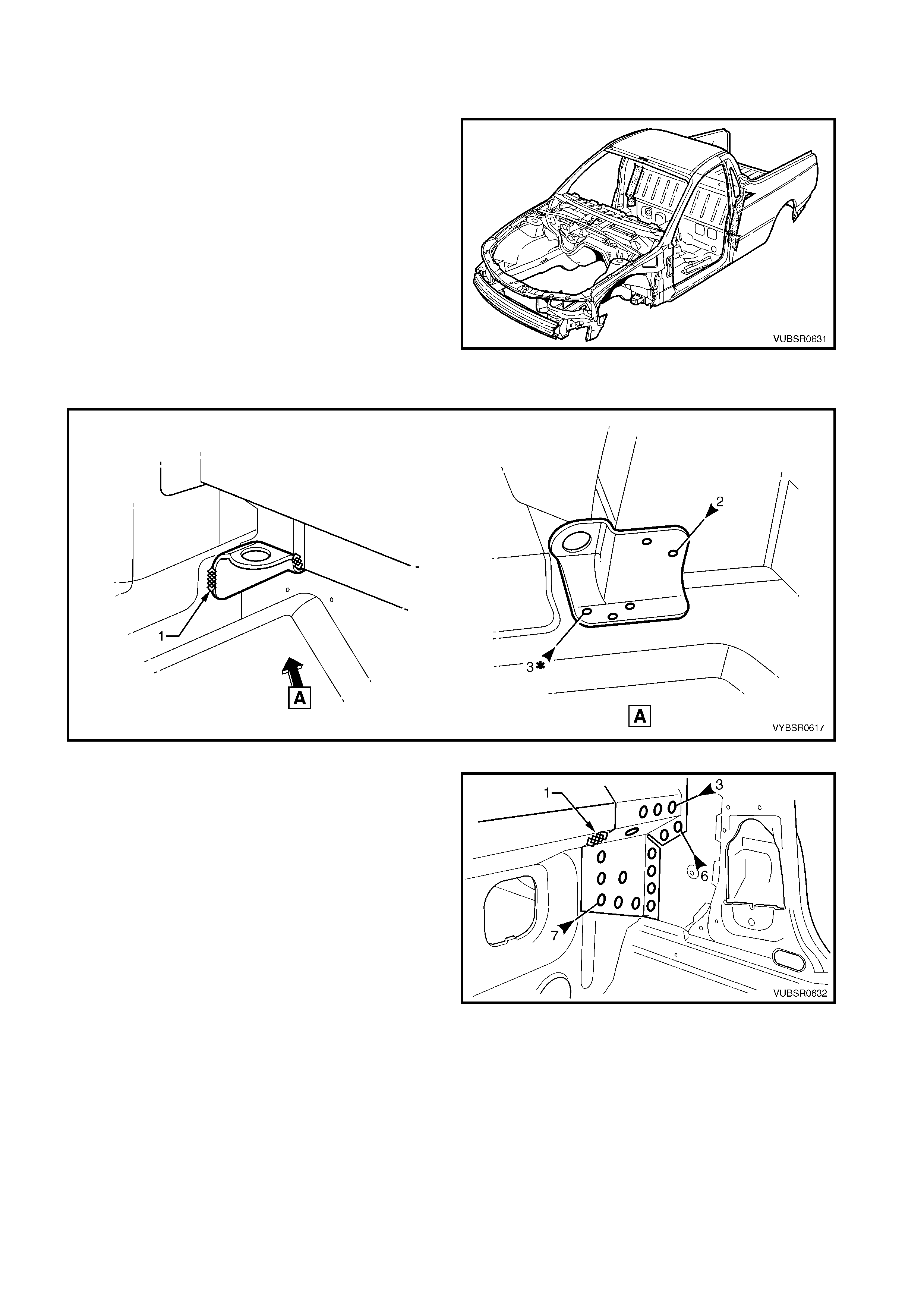
5. Grind off the two MIG welds (1) and spot cut the
welds attaching the front tie down bracket to each
side of the vehicle, refer to Figure 6-49.
Figure 6-48
Figure 6-49
6. Spot cut the welds attaching the front seatback
panel outer to the:
- front floor rear extension assembly, seven
places,
- side inner upper panel, six places,
- load floor panel outer extension, three places.
7. Grind off the MIG weld (1) attaching the front f loor
rear extension assembly to the front seatback
panel outer.
Figure 6-50
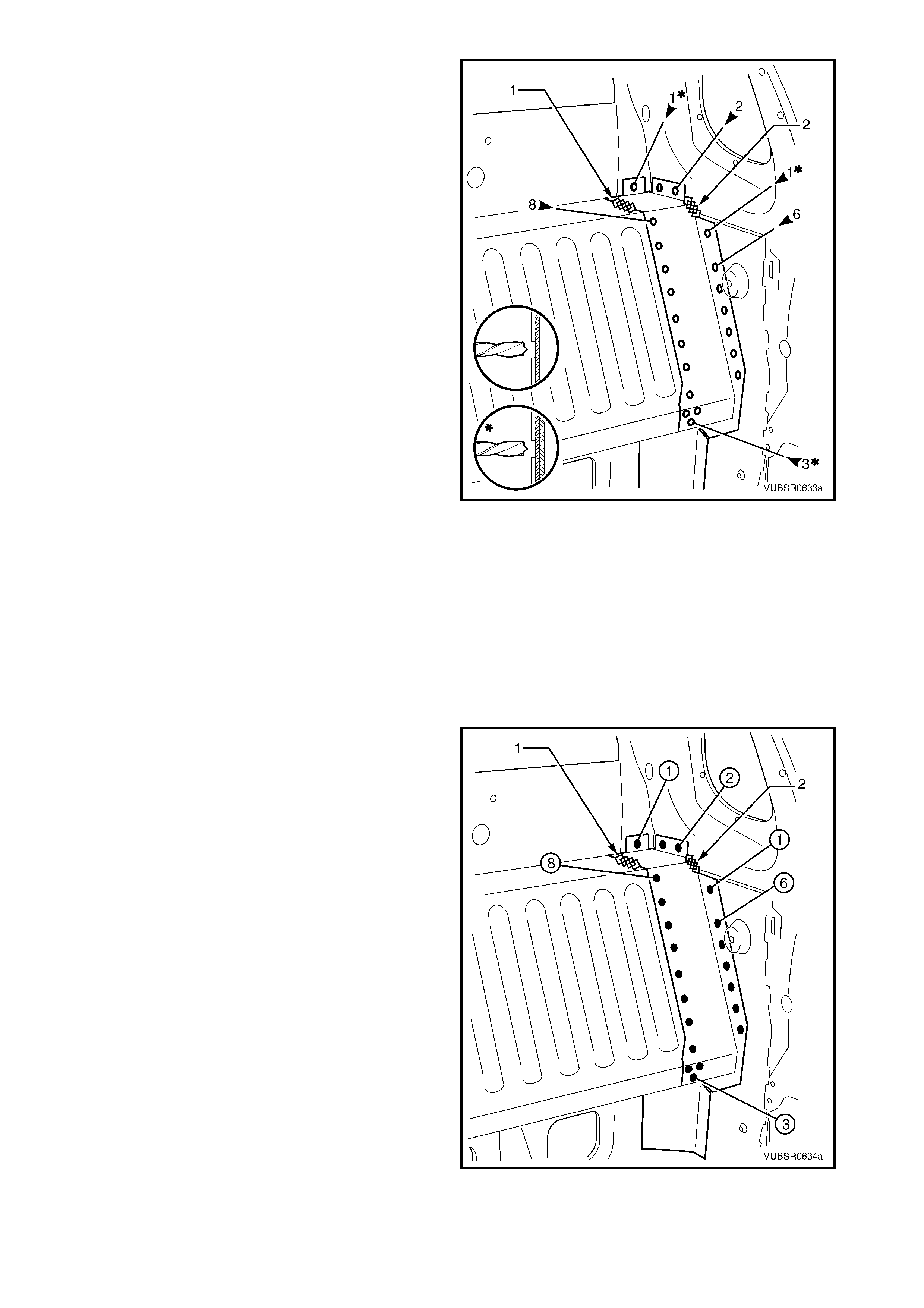
8. Spot cut the welds attaching the front seatback
panel outer to the:
- front seatback panel, eight places,
- side inner upper front panel & side inner upper
front panel, one place,
- side inner upper front panel, two places,
- side inner upper front panel & side inner upper
panel, one place,
- side inner upper panel, six places,
- front s eatback panel & f ront f loor rear extension
assembly, three places.
9. Grind of f the MIG welds (1 & 2) attac hing the front
seatback panel outer to the front seatback panel
and side inner upper front panel.
10. Remove the panel(s) from the vehicle and repair
any damage to adjacent panels as required.
11. Check and rectify the alignment of the body as
required, refer to 3. BODY DIMENSIONS in
Section 3C.
Figure 6-51
REPLACE
NOTE 1: Spot welding is the preferred method for attaching of panels and should be used whenever possible.
Where the spot welding equipment available will not access the required weld position, a plug weld should be
performed.
NOTE 2: The s ame number and pos ition of spot welds ( or plug welds) s hould be used when replacing the panel,
as was used during manufacture, in order to maintain the original structural strength of the vehicle.
1. As required, mark the new panel with drilling locations in preparation for plug welding. Drill holes as required.
2. Prepare all mating surfaces and treat with Weld Through Primer (Item 1) as required, refer to
5. BODY SEALING, ADHESIVES & DEADENERS in Section 3C.
3. Clamp the front seatback panel outer in position.
4. Spot or plug weld the front s eatback panel outer to
the:
- front seatback panel, eight places,
- side inner upper front panel & side inner upper
front panel, one place,
- side inner upper front panel, two places,
- side inner upper front panel & side inner upper
panel, one place,
- side inner upper panel, six places,
- front s eatback panel & f ront f loor rear extension
assembly, three places.
5. MIG weld the front seatback panel outer (1) 50
mm to the front seatback panel and (2) 25 mm to
the side inner upper front panel.
Figure 6-52

6. Spot or plug weld the front s eatback panel outer to
the:
- front floor rear extension assembly, seven
places,
- side inner upper panel, six places,
- load floor panel outer extension, three places.
7. MIG weld (1) 25 mm the front floor rear extension
assembly to the front seatback panel outer.
8. MIG weld (1) two places and spot or plug weld the
front tie down bracket, each side of the vehicle,
refer to Figure 6-54.
Figure 6-53
Figure 6-54
9. Replace the adjoining removed panels as required, refer to the relevant Section in this Supplement.
10. Refinish and paint panels and other components as required. Refer to Section 3, 1.3 PAINT REFINISHING.
11. Apply Joint Sealer (Item 3) as required. Refer to 5. BODY SEALING, ADHESIVES & DEADENERS in
Section 3C.
12. Apply Cavity W ax (Item 8) as required to the ins ide of any box s ections or areas inacces sible to paint, refer
to 6. CAVITY WAX in Section 3C.
13. Install the rear window, refer to Section 1A6 STATIONARY WINDOWS in the MY 2003 VY & V2 II Series
Service Information.
14. Install the remaining components as described in the MY 2003 VY & V2 II Series Service Information.
3.3 FRONT SEATBACK PANEL – REPLACE
REMOVE
1. Remove the adjacent bolt-on panels and
components as described in the appropriate
Section of the MY 2003 VY & V2 Series II Service
Information.
2. Remove the rear window, refer Section 1A6
STATIONARY WINDOW in the MY 2003 VY & V2
Series II Service Information.
3. Secure the vehicle on a suitable fixture. As a
minimum, support the structural sections of the
vehicle on safety stands.
4. Remove the adjacent panels as required, refer to
the relevant Section in this Supplement.
5. Spot cut the welds attaching the front seatback
panel to the front floor rear extension assembly
and front seat back panel outer, refer to Figure
6-56.
6. Grind off the MIG welds (1) attaching the front
seatback panel to the front seatback panel outer
and side inner upper front panel, refer to Figure
6-56.
Figure 6-55
Figure 6-56
7. Spot cut the 18 welds attaching the front seatback
panel to the front floor rear extension
reinforcement.
8. Spot cut the 40 welds attaching the front seatback
panel to the load compartment extension outer
panel, refer to Figure 6-58.
NOTE: If the load compartment extension outer panel
is also being removed, this procedure is not required.
Figure 6-57
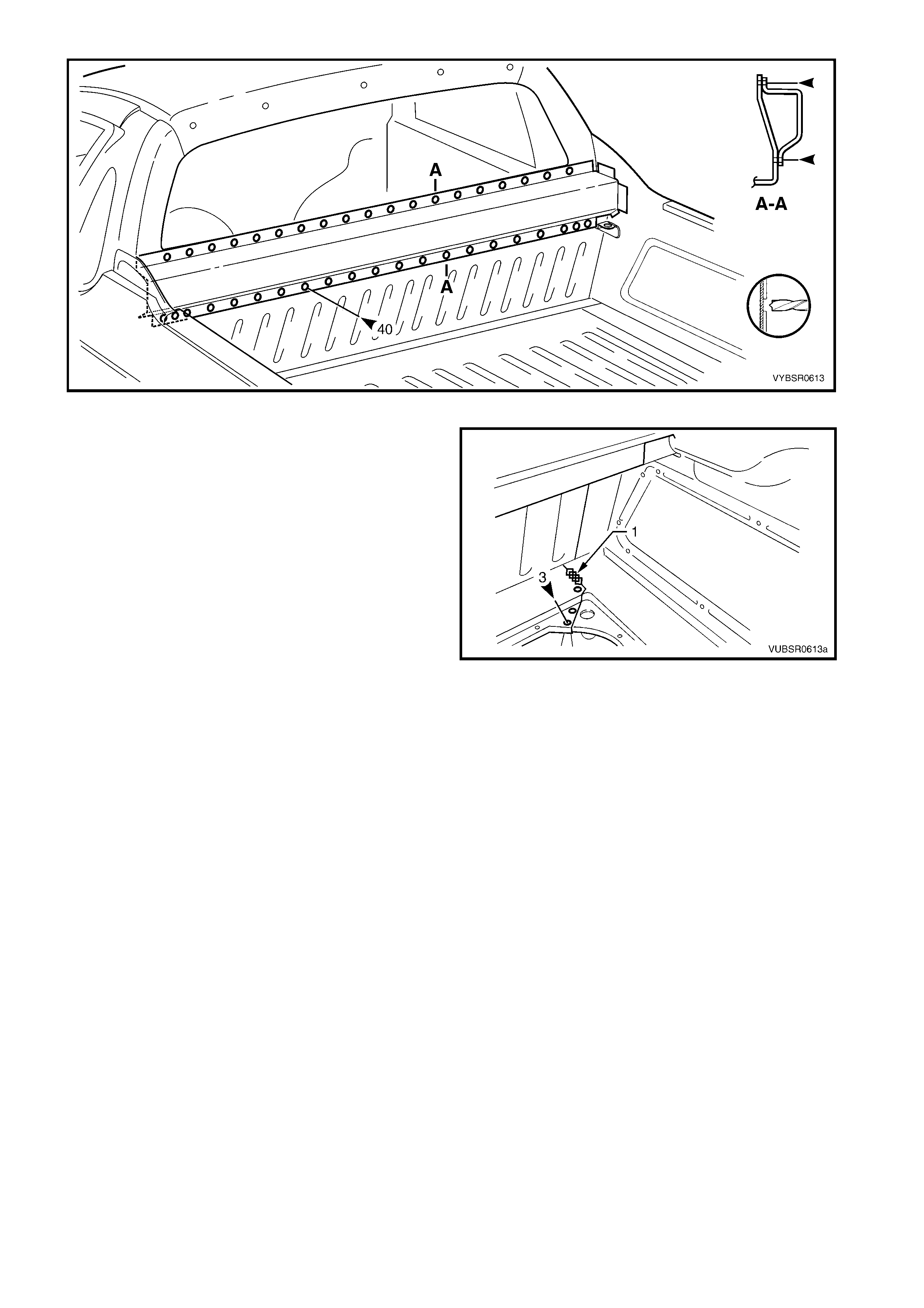
Figure 6-58
9. Spot cut the three welds and grind off the MIG
weld (1) attaching the front seatback panel to the
load floor panel outer extension.
10. If the load compartment extension outer panel
is also being removed, refer to
3.1 LOAD COMPARTM ENT EXT ENSION O UTER
PANEL & BRACKET – REPLACE.
11. Rem ove the panel from the vehicle and repair any
damage to adjacent panels as required.
12. Check and rectify the alignment of the body as
required, refer to 3. BODY DIMENSIONS in
Section 3C.
Figure 6-59
REPLACE
NOTE 1: Spot welding is the preferred method for attaching of panels and should be used whenever possible.
Where the spot welding equipment available will not access the required weld position, a plug weld should be
performed.
NOTE 2: The s ame number and pos ition of spot welds ( or plug welds) s hould be used when replacing the panel,
as was used during manufacture, in order to maintain the original structural strength of the vehicle.
1. As required, mark the new panel with drilling locations in preparation for plug welding. Drill holes as required.
2. Prepare all mating surfaces and treat with Weld Through Primer (Item 1) as required, refer to
5. BODY SEALING, ADHESIVES & DEADENERS in Section 3C.
3. Clamp the front seatback panel in position.
4. Spot or plug weld the front seatback panel to the
front floor rear extension reinforcement.
5. Spot or plug weld the front seatback panel to the
front floor rear extension assembly and front seat
back panel outer, refer to Figure 6-61.
6. MIG weld 50mm two places each side (1), the front
seatback panel to the and front seat back panel
outer and side inner upper front panel, refer to
Figure 6-61.
Figure 6-60
Figure 6-61
7. If the load compartment extension outer panel
upper was not removed, spot or plug weld the front
seatback panel 40 places.
Figure 6-62
8. Spot or plug weld three places and MIG weld
25mm one place (1), the front seatback panel to
the load floor panel outer extension.
9. Replac e the adj oining re moved panels as required,
refer to the relevant Section in this Supplement.
10. Refinish and paint panels and other components
as required. Refer to Section 3, 1.3 PAINT
REFINISHING.
11. Apply Joint Sealer (Item 3) as required. Refer to
5. BODY SEALING, ADHESIVES & DEAD ENERS
in Section 3C.
12. Apply Cavity W a x ( Item 8) as requir ed to the inside
of any box sections or areas inaccessible to paint,
refer to 6. CAVITY WAX in Section 3C.
13. Install the rear window, refer to Section 1A6
STATIONARY WINDOWS in the MY 2003 VY &
V2 II Series Service Information.
14. Install the remaining components as described in
the MY 2003 VY & V2 II Series Service
Information.
Figure 6-63
3.4 FRONT FLOOR REAR EXTENSION ASSEMBLY – REPLACE
NOTE: This procedure describes removing the front
floor rear extension, front floor rear extension
reinforcement and front fuel tank brackets as an
assembly. As the parts are serviced separately, their
installation is described as they would be replaced.
REMOVE
1. Remove the adjacent bolt-on panels and
components as described in the appropriate
Section of the MY 2003 VY & V2 Series II Service
Information.
2. Secure the vehicle on a suitable fixture and
support the structural sections of the vehicle on
safety stands.
3. Remove the adjacent panels as required, refer to
the relevant Section in this Supplement.
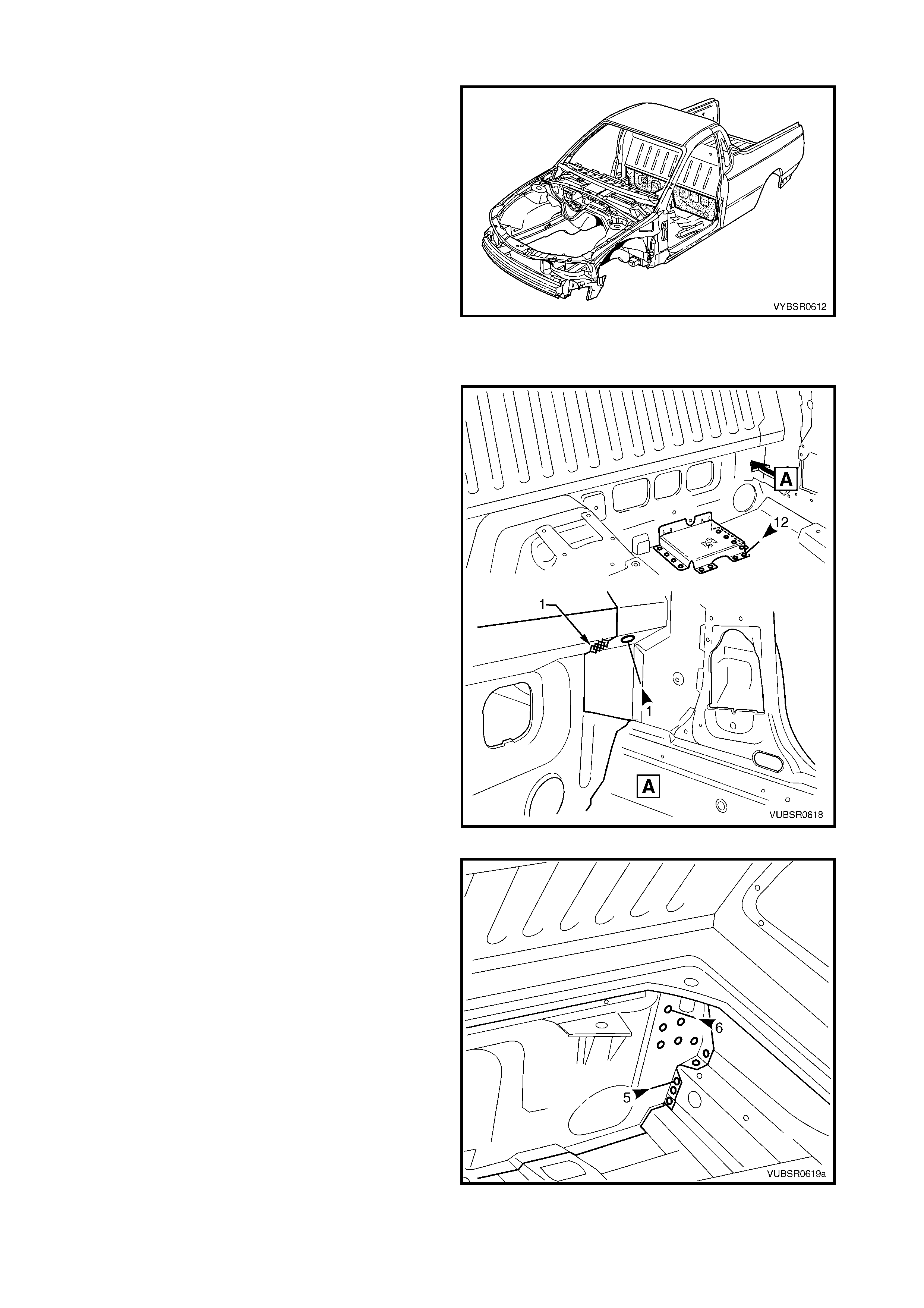
Figure 6-64
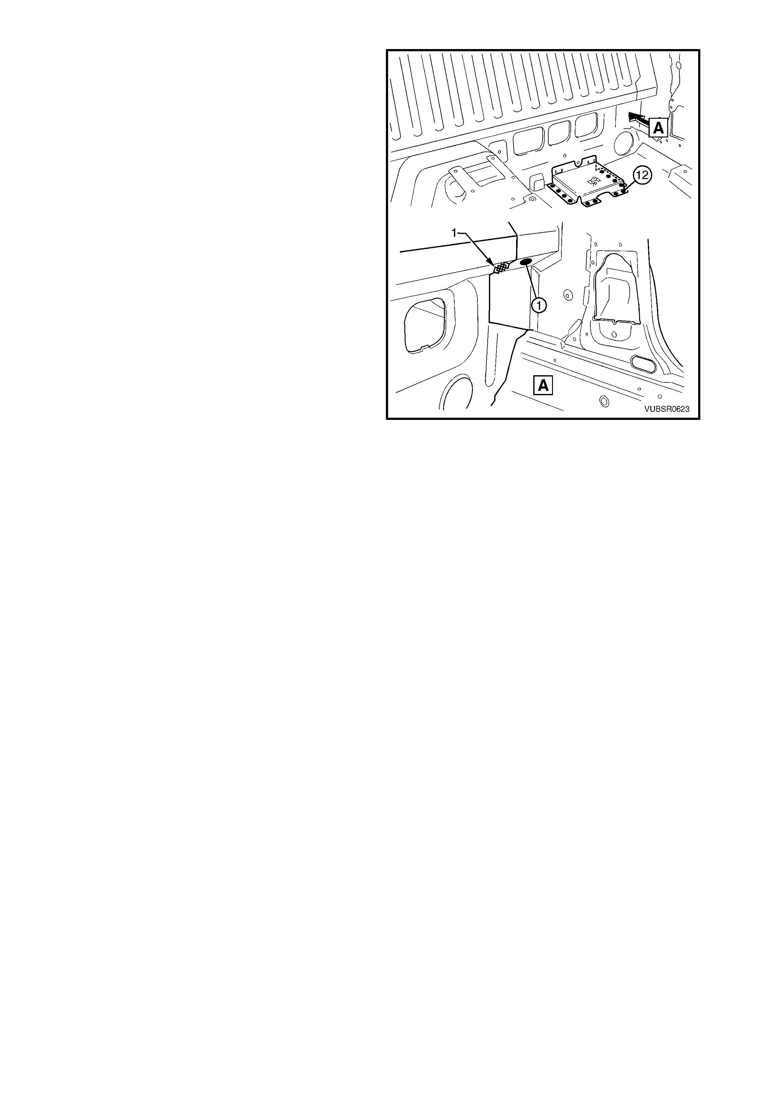
4. If required, s pot cut the 12 welds attaching the jack
stowage bracket to the floor.
5. Spot cut the weld and grind off the MIG weld (1)
each side, attaching the front floor rear extension
to the front seatback panel outer, refer to View A.
6. If the front seatback panel has not been removed,
rem ove the welds attaching it to the front floor rear
extension, ref er 3.3 FRONT SEATBACK PANEL –
REPLACE in this Section.
Figure 6-65
7. Spot cut the welds attaching the front floor rear
extension to the:
a. front seatback panel outer, six places each
side,
b. inner rocker panel, five places each side,
8. Spot cut the 31 welds attaching the front floor rear
extension to the to front floor panel, refer to Figure
6-67.
9. Remove the front floor rear extension assembly
from the vehicle and repair any damage to
adjacent panels.
10. Check and rectify the alignment of the body as
required, refer to 3. BODY DIMENSIONS in
Section 3C.
Figure 6-66
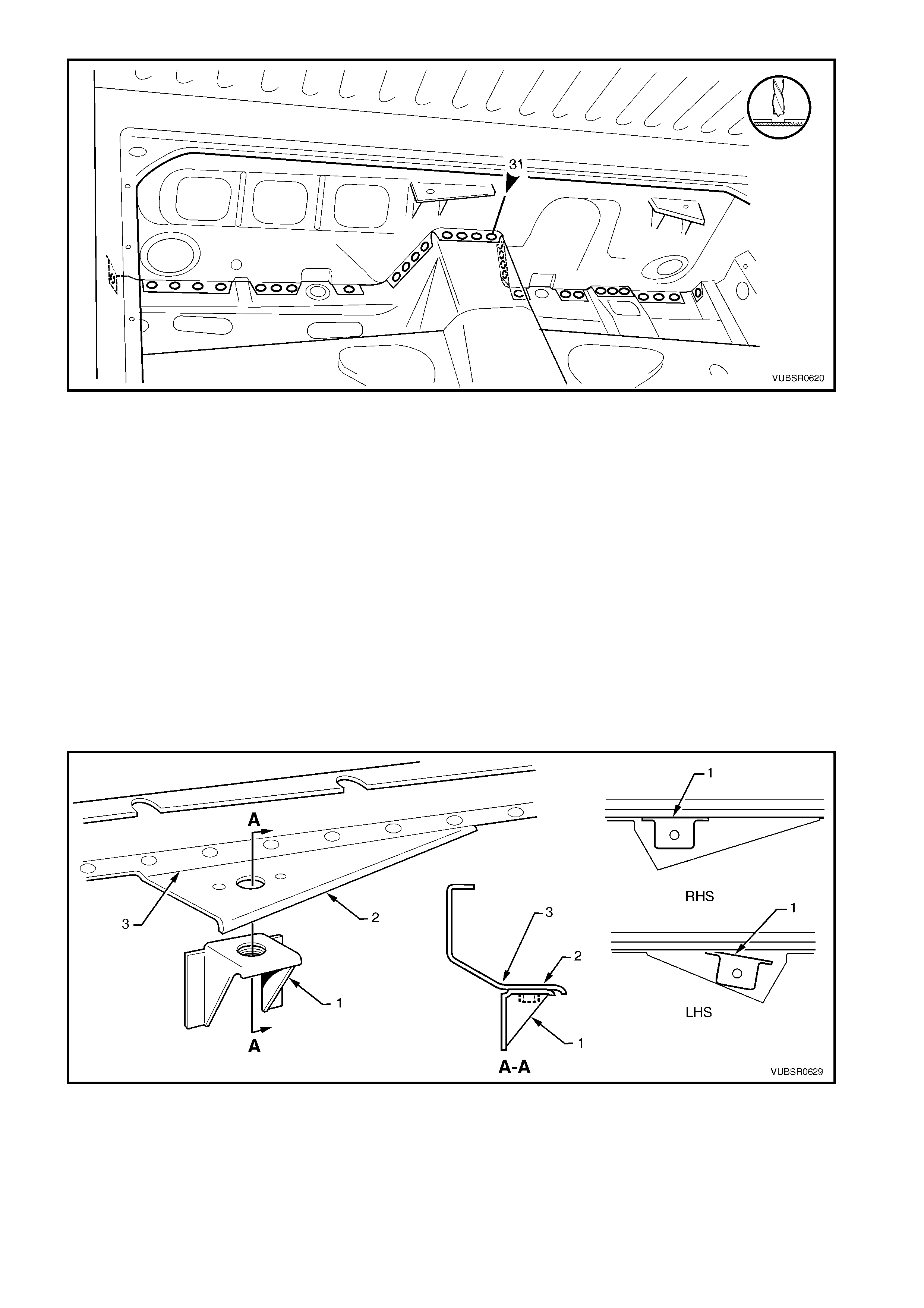
Figure 6-67
REPLACE
NOTE 1: Spot welding is the preferred method for attaching of panels and should be used whenever possible.
Where the spot welding equipment available will not access the required weld position, a plug weld should be
performed.
NOTE 2: The s ame number and pos ition of spot welds ( or plug welds) s hould be used when replacing the panel,
as was used during manufacture, in order to maintain the original structural strength of the vehicle.
1. As required, mark the new panels with drilling locations in preparation for plug welding. Drill holes as
required.
2. Prepare all mating surfaces and treat with Weld Through Primer (Item 1) as required, refer to
5. BODY SEALING, ADHESIVES & DEADENERS in Section 3C.
3. Prior to installing the front floor r ear extens ion, fit the left- hand fuel tank br acket ( 1) on to the front f loor rear
extension reinforcement (2) as shown, aligning the fuel tank mounting stud within the reinforcement hole.
The bracket is to be parallel to the fold (3), refer to Figure 6-68. Tack weld in position.
4. Repeat for the right-hand fuel tank bracket, noting that it does not sit parallel. Temporarily fit the
reinforcement onto the front floor rear extension to obtain the correct angle while ensuring the fuel tank
mounting stud remains aligned within the reinforcement hole.
Figure 6-68
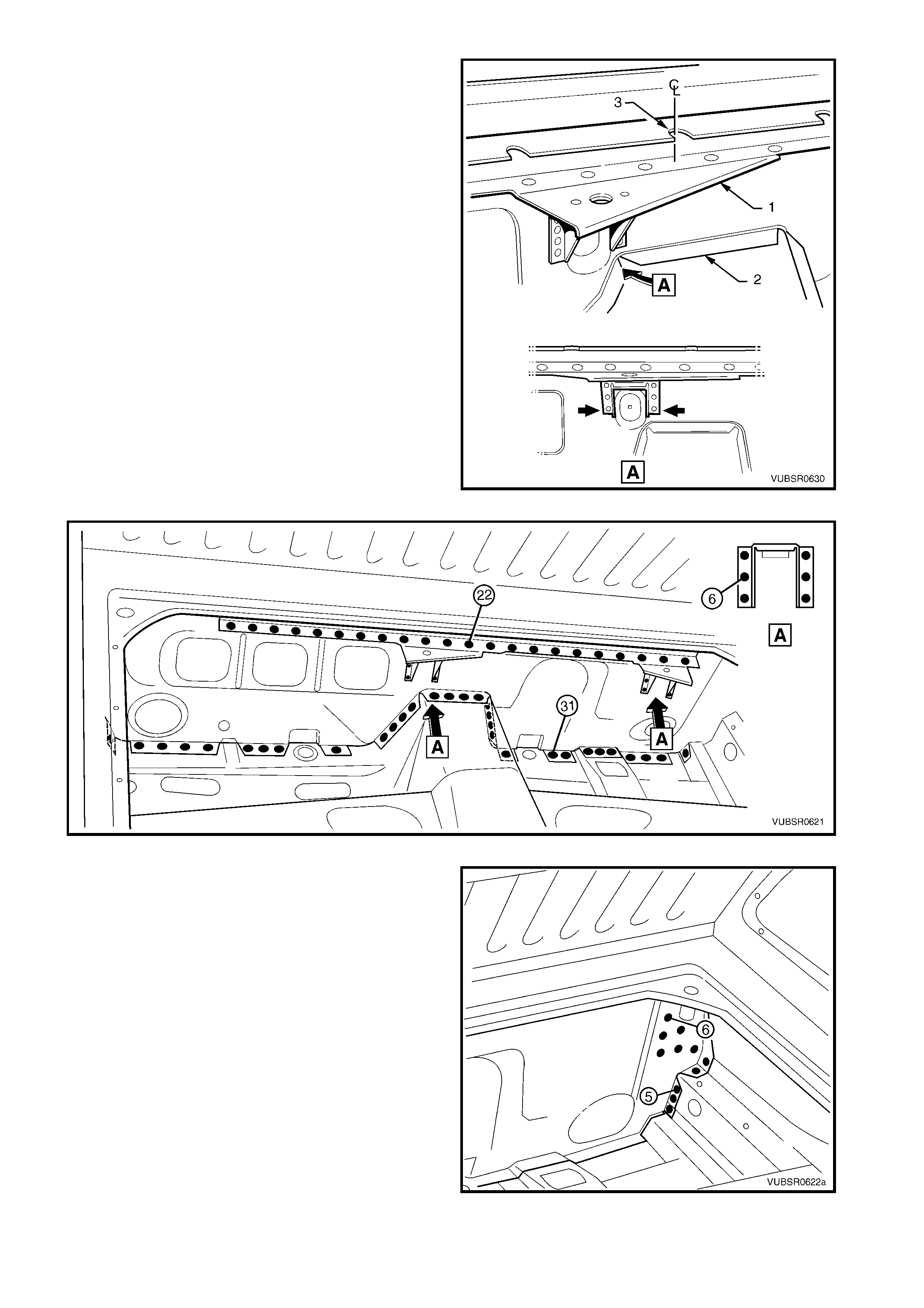
5. Fit the reinforcement and fuel tank bracket
assembly (1) on to the front floor rear extension
(2). Position the left-hand fuel tank bracket over
the rib in the front f loor rear extension as shown A.
Tack weld the reinforcement in position.
NOTE: Check the notch in the reinforcement (3) is
central on front floor rear extension assembly.
6. Install and clamp the front floor rear extension
assembly in position.
NOTE: Test fit the front seatback panel if it is not
installed, to ensure it seats correctly with the
reinforcement. Also test fit the fuel tank to ensure it
aligns with the mounting studs.
7. Spot or plug weld 31 places, the front floor rear
extension to the floor panel, refer to Figure 6-70.
8. Spot or plug weld 22 places, the front floor rear
extension reinforcement to the front floor rear
extension, refer to Figure 6-70.
9. Spot or plug weld six places each, the fuel tank
brackets to the front floor rear extension, refer to
Figure 6-70.
Figure 6-69
Figure 6-70
10. Spot or plug weld six places each side, the front
floor rear extension to the to the front seatback
panel outer.
11. Spot or plug weld five places each side, the front
floor rear extension to the to inner rocker panel.
Figure 6-71
12. Spot or plug weld one place each side, the front
floor rear extension to the to the front seatback
panel outer, refer to View A.
13. MIG weld 25 mm long, the front floor rear
extension to the to the front seatback panel outer,
refer to View A.
14. Spot or plug weld the jack stowage bracket to the
floor panel, if it was removed.
15. Install the front s eatback panel if rem oved, refer to
3.3 FRONT SEA TBACK PANEL – REPLACE.
16. Replace the adjoining removed panels as required,
refer to the relevant Section in this Supplement.
17. Refinish and paint panels and other components
as required. Refer to Section 3, 1.3 PAINT
REFINISHING.
18. Apply Joint Sealer (Item 3) as required. Refer to
5. BODY SEALING, ADHESIVES & DEADENERS
in Section 3C.
19. Apply Cavity W a x ( Item 8) as requir ed to the inside
of any box sections or areas inaccessible to paint,
refer to 6. CAVITY WAX in Section 3C
20. Install the remaining components as described in
the MY 2003 VY & V2 II Series Service
Information.
Figure 6-72