
SECTION 7C – BODY SIDE – UTILITY
IMPORTANT
Before performing any Service Operation or other procedure described in this Section, refer to
Section 00 CAUTIONS AND NOTES and Section 2 PRECAUTIONS in this Supplement for correct
workshop practices with regard to safety and/or property damage.
CAUTION
The Structure of the M Y 2003 VY & V2 Series II body shell has been developed using complex design
and development techniques. In addition to meeting all required standards, the v ehicle body is also a
critical part of the overall safety systems. It is therefore imperative the repair procedures described
here are adhered to during all vehicle body repairs.
1. GENERAL DESCRIPTION
1.1 BODY SIDE COMPONENTS
2. SERVICE OPERATIONS
2.1 REAR QUARTER PANEL – REPLACE
REMOVE
REPLACE
2.2 QUARTER PANEL EXTENSION –
REPLACE
REMOVE
REPLACE
2.3 QUARTER INNER LOWER REAR
EXTENSION – REPLACE
REMOVE
REPLACE
2.4 QUARTER OUTER LOWER REAR PANEL –
REPLACE
REMOVE
REPLACE
2.5 QUARTER LOWER REAR PANEL –
REPLACE
REMOVE
REPLACE
2.6 DOOR OPENING FRAME ASSEMBLY –
REPLACE
REMOVE
REPLACE
2.7 DOOR OPENING FRAME ASSEMBLY –
PARTIAL REPLACE, HINGE PILLAR
REMOVE
REPLACE
2.8 DOOR OPENING FRAME ASSEMBLY –
PARTIAL REPLACE, CENTRE PILLAR
REMOVE
REPLACE
2.9 DOOR OPENING FRAME ASSEMBLY –
PARTIAL REPLACE, ROCKER PANEL
REMOVE
REPLACE
2.10 FENDER LOWER REAR BRACKET –
REPLACE
2.11 HINGE PILLAR INNER PANEL ASSEMBLY –
REPLACE
REMOVE
REPLACE
2.12 QUARTER INNER & REAR WHEELHOUSE
BRACE – REPLACE
REMOVE
REPLACE
2.13 QUARTER PANEL INNER ASSEMBLY –
REPLACE
REMOVE
REPLACE
2.14 SIDE INNER UPPER PANEL – REPLACE
REMOVE
REPLACE
2.15 SIDE INNER UPPER PANEL – PARTIAL
REPLACE
REMOVE
REPLACE
2.16 SIDE INNER UPPER FRONT PANEL –
REPLACE
REMOVE
REPLACE
2.17 LOAD FLOOR PANEL OUTER EXTENSION
& LOAD FLOOR PANEL OUTER
REINFORCEMENT – REPLACE
REMOVE
REPLACE
2.18 REAR WHEELHOUSE INNER PANEL –
REPLACE
REMOVE
REPLACE
1. GENERAL DESCRI PTI O N
This Section des cribes the replacem ent proc edures for the body side com ponents of the MY 2003 VY Series Utility
body structure. Removal of bolt-on panels and mechanical components is not covered.
When repairing the body side of the vehicle, care must be taken to ensure the structure is returned to its original
production configuration. This is especially important to maintain side impact standards.
This Section includes door opening f ram e ass em bly partial replacem ent procedur es f or the hinge pillar, c entre pillar
and rocker panel. These procedures must be followed carefully, as they can involve hidden reinforcement panels.
The cutting locations specified are the only places allowable.
NOTE: It is imperative that the correct body adhesives, sealers, deadeners and cavity waxes are used when
repairing the body structure of MY 2003 VY Series Utility vehicles. Refer to 5. BODY SEALING, ADHESIVES &
DEADENERS and 6. CAVITY WAX in Section 3C for details of the correct materials and their commercially
available equivalents.
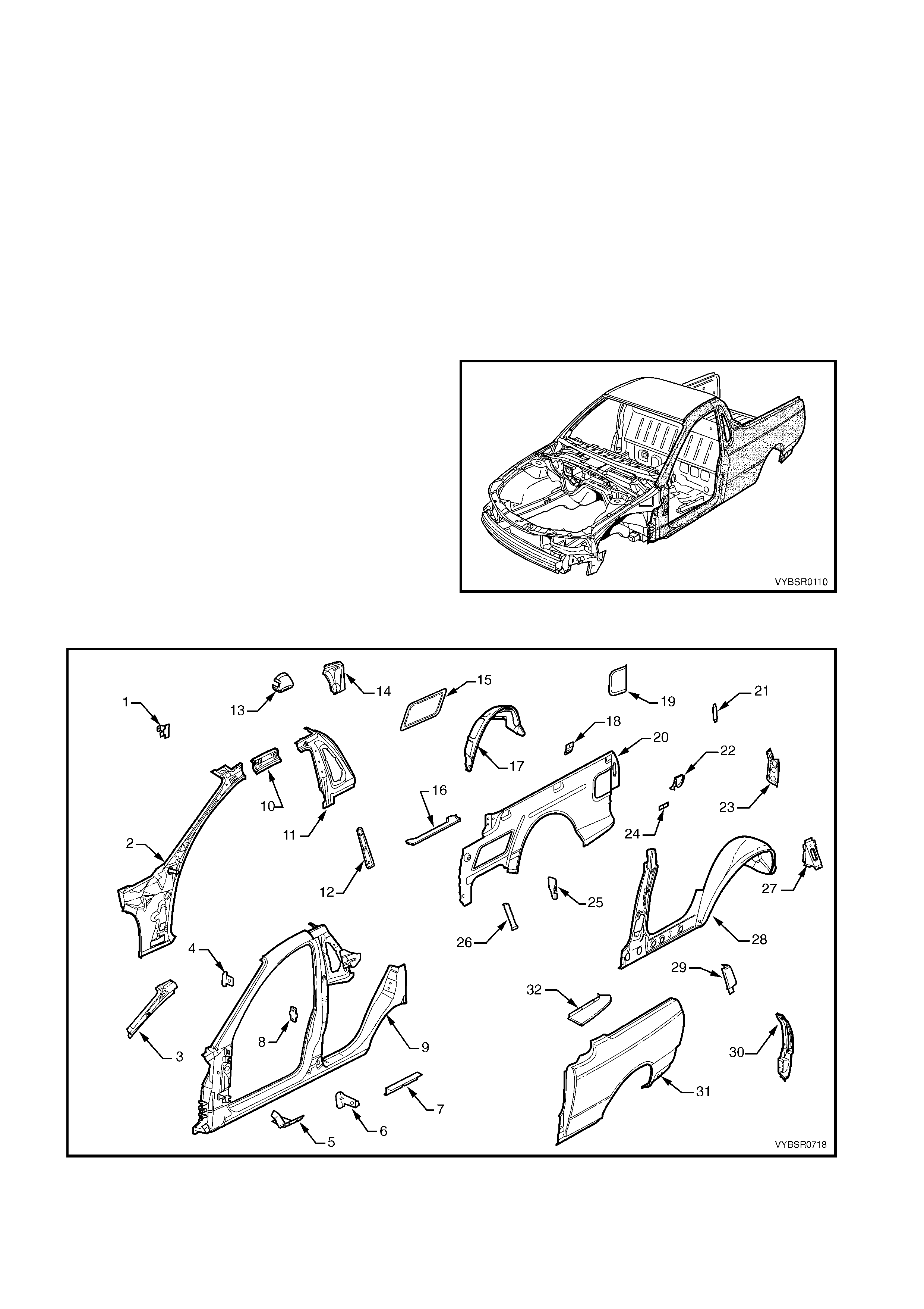
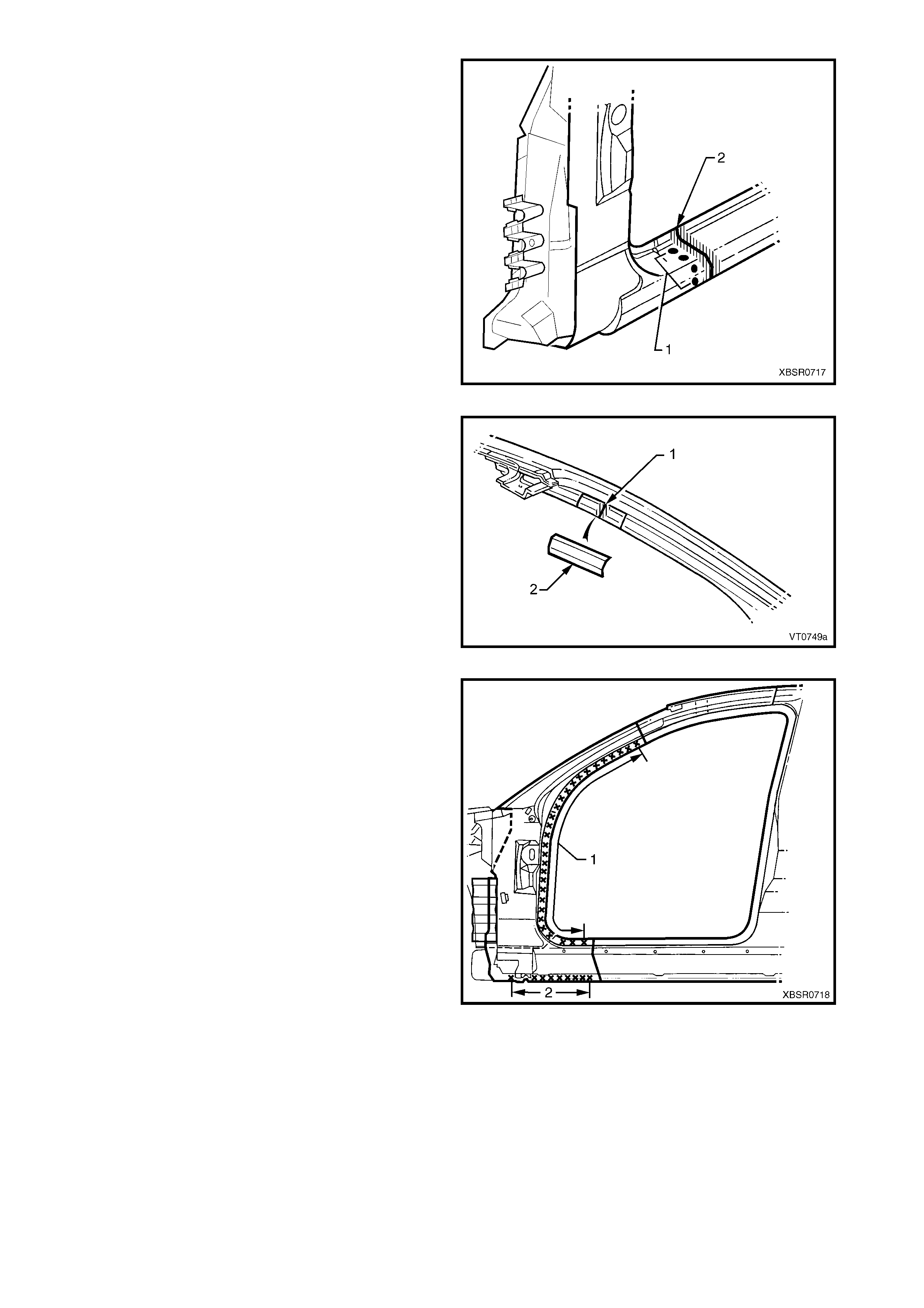
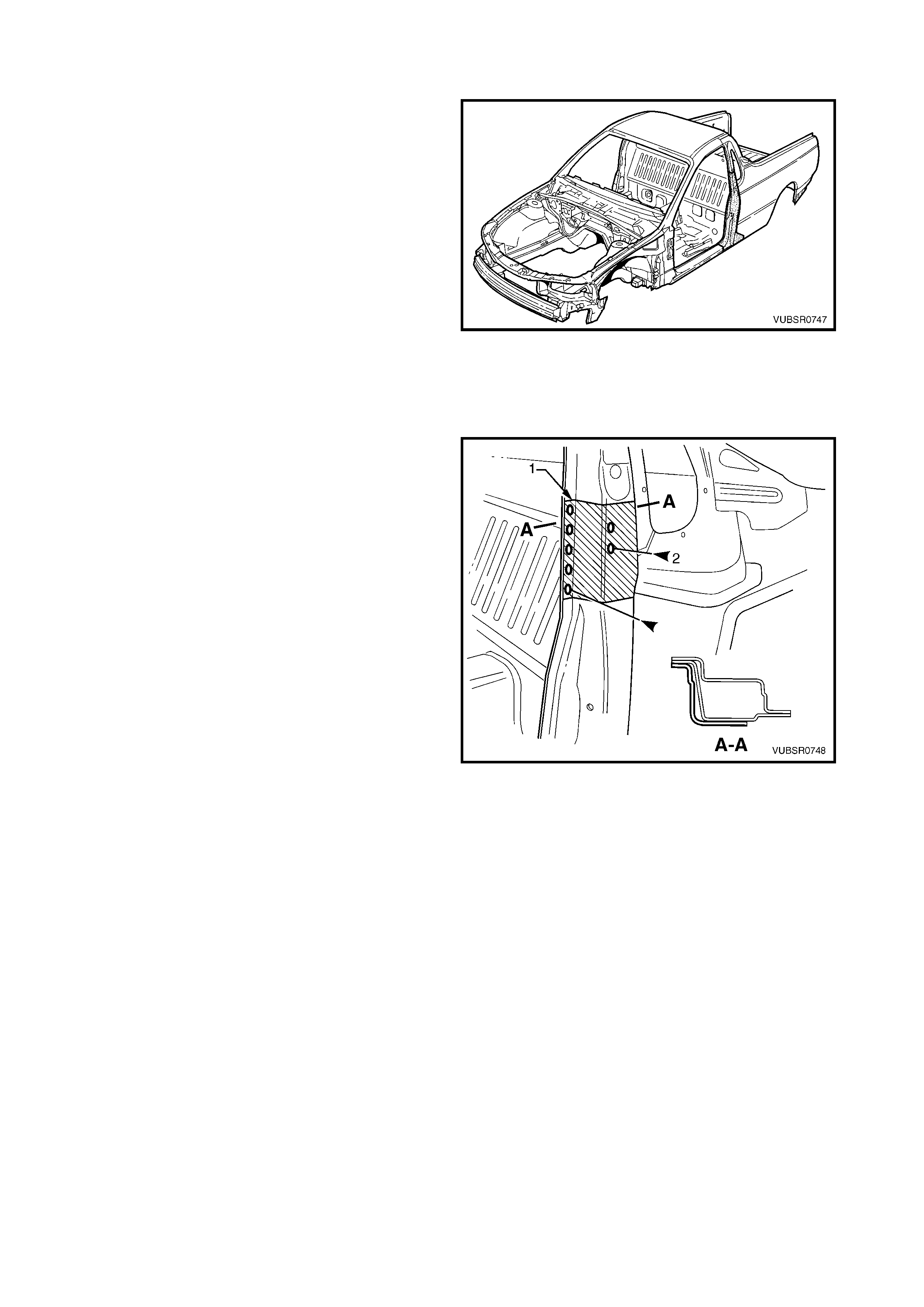
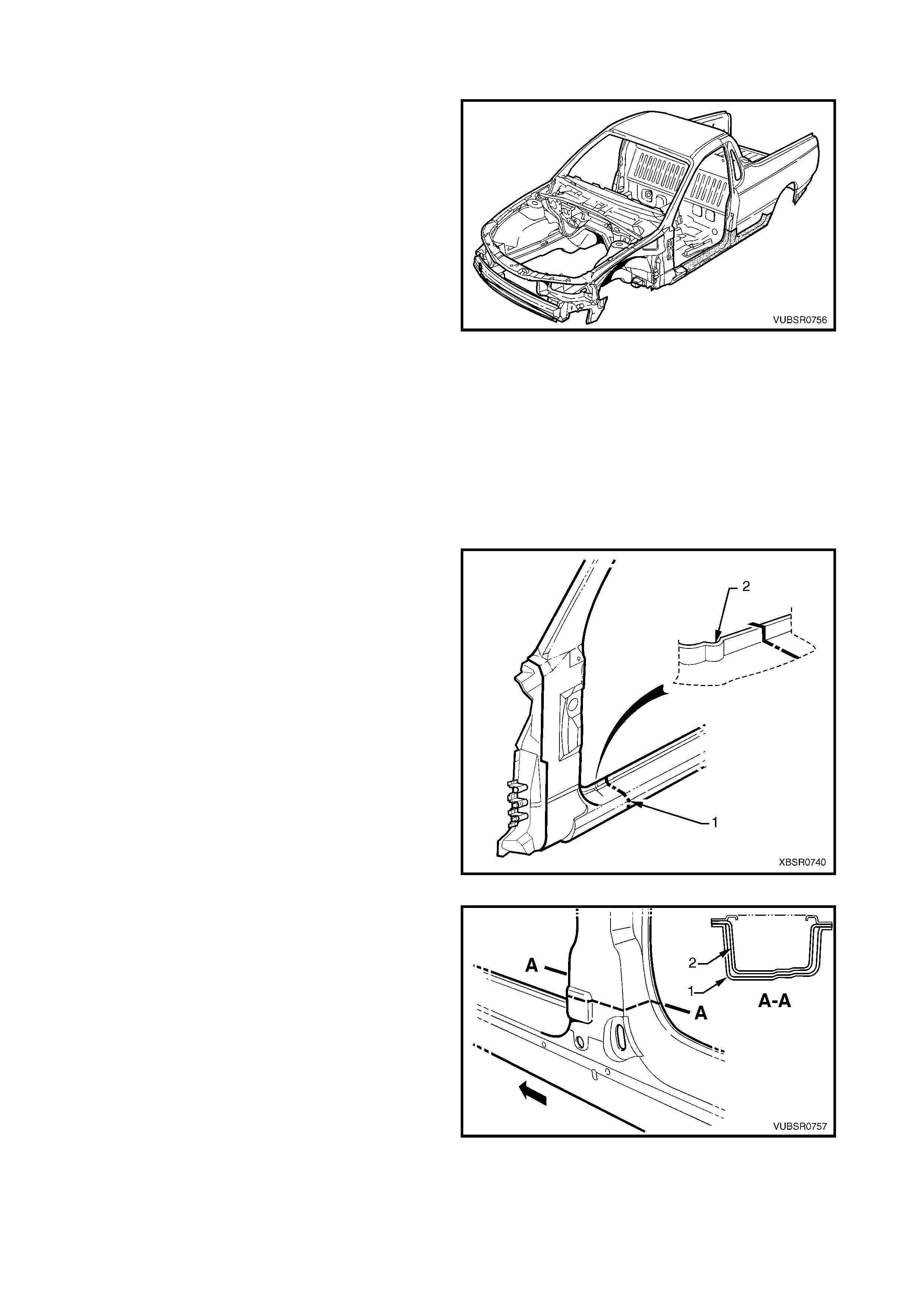
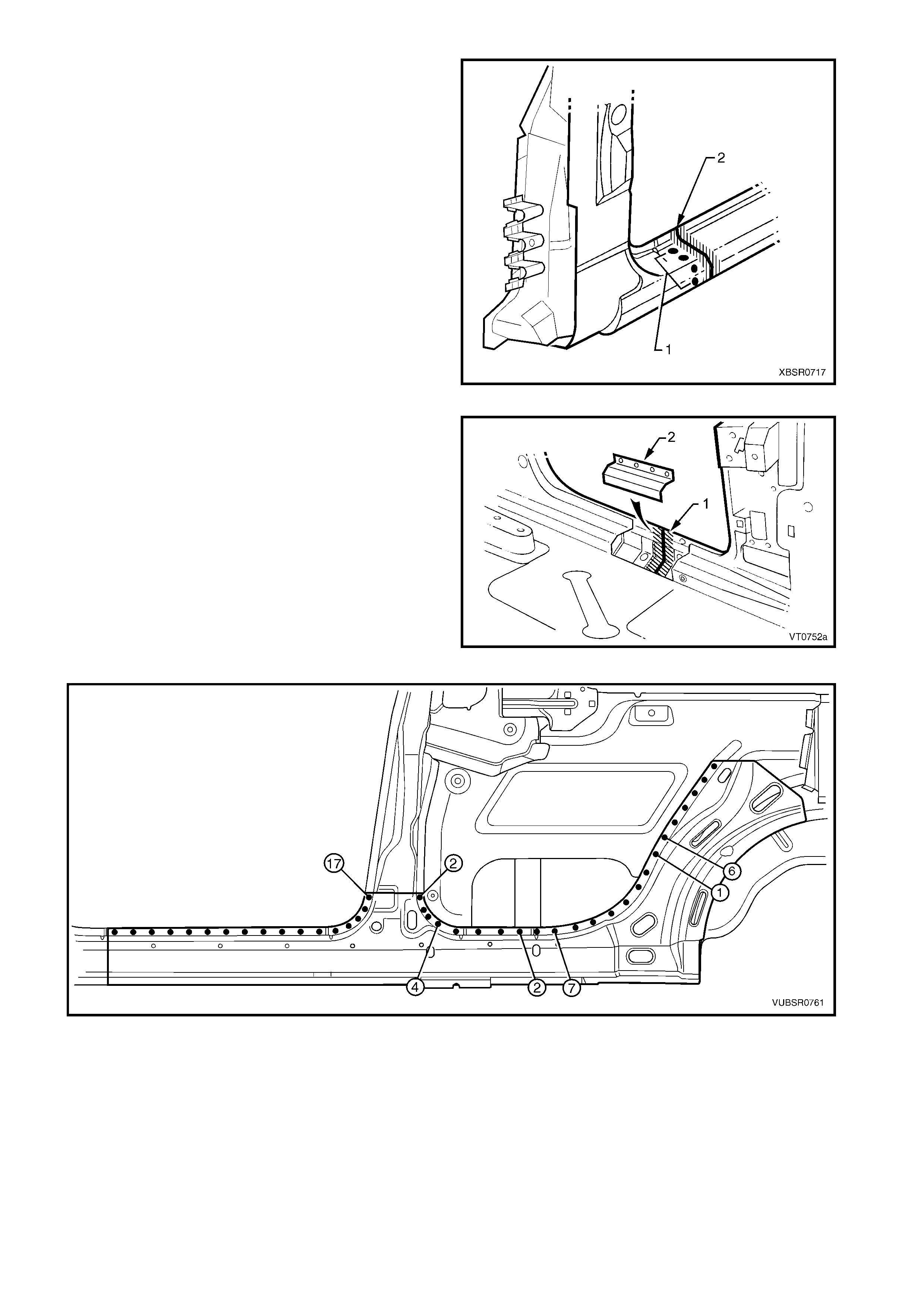
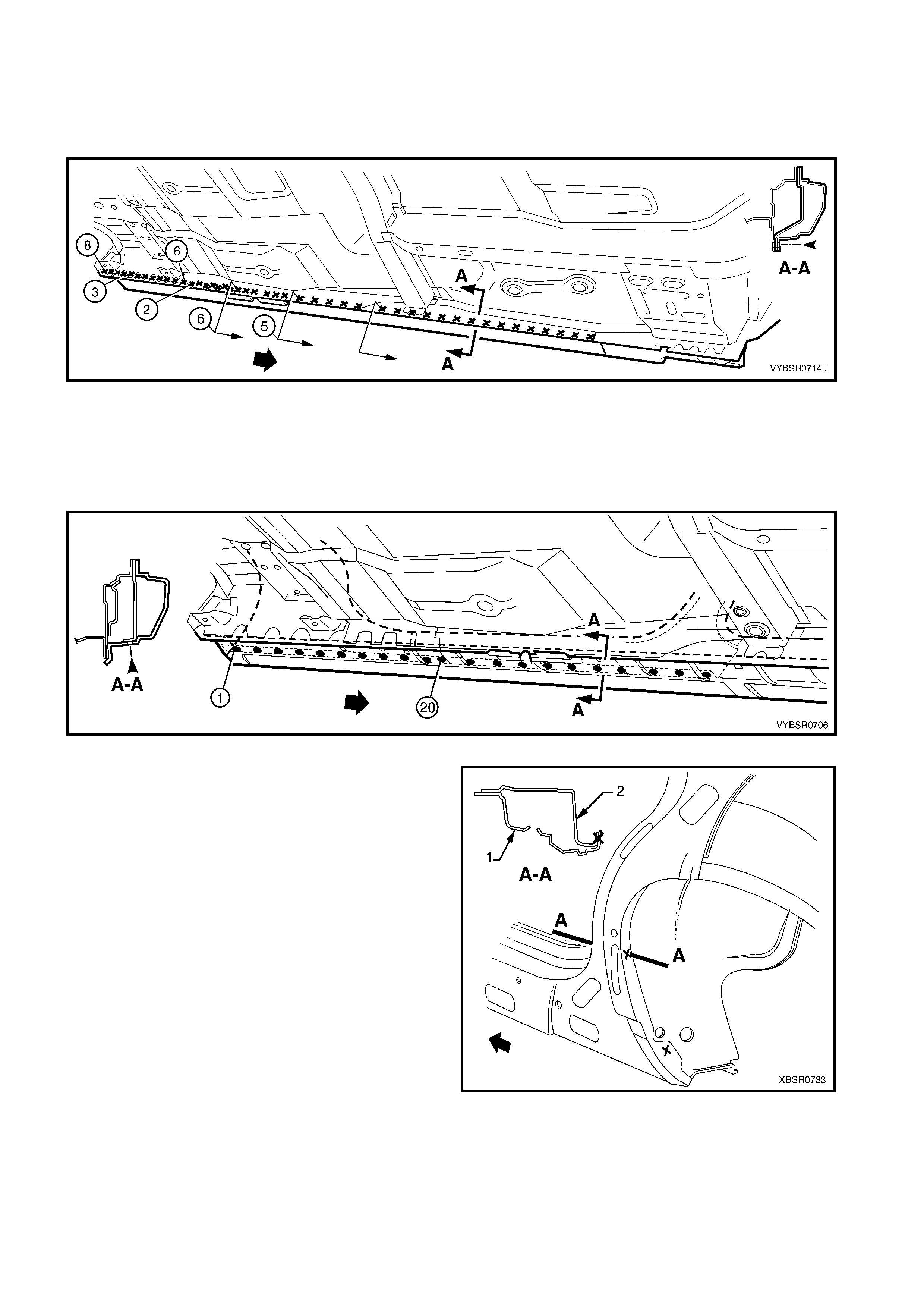
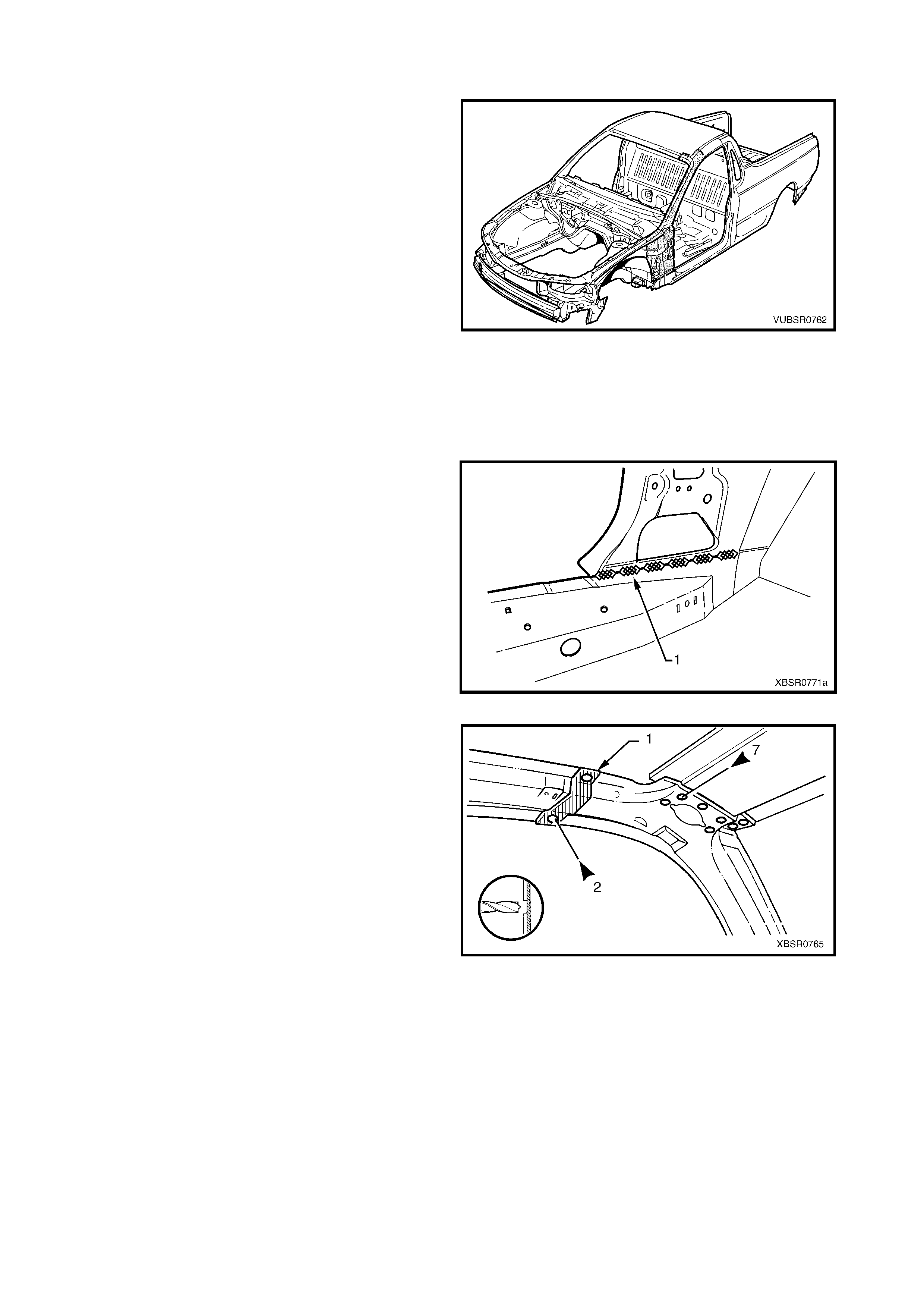
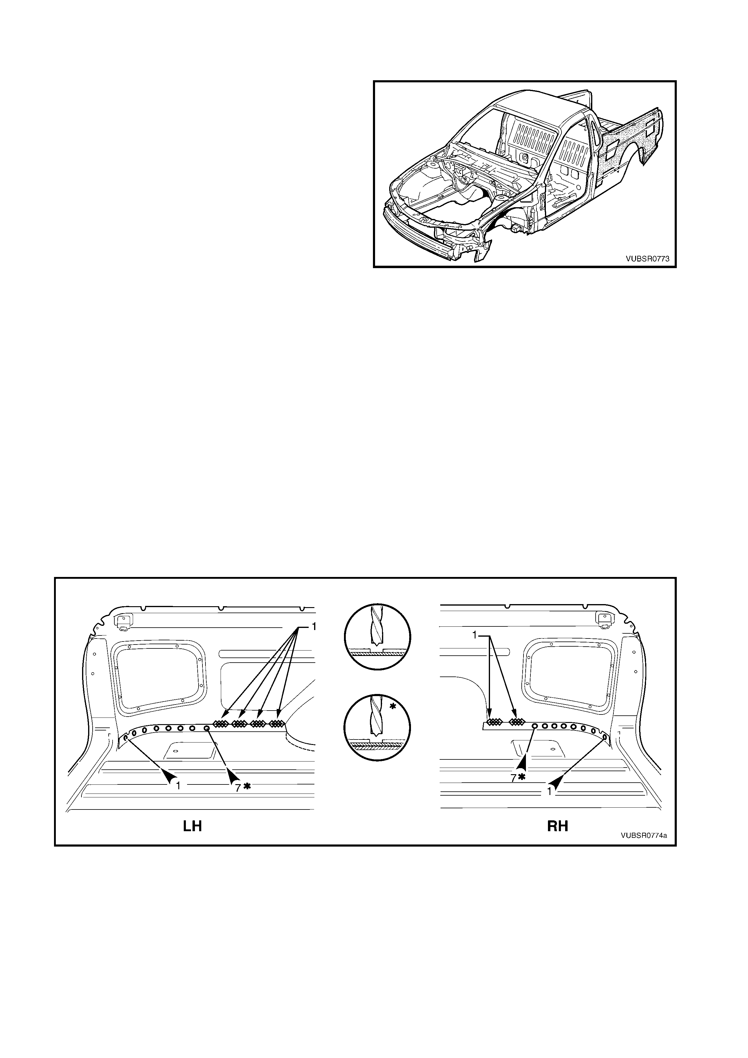
1.1 BODY SIDE COMPONENTS
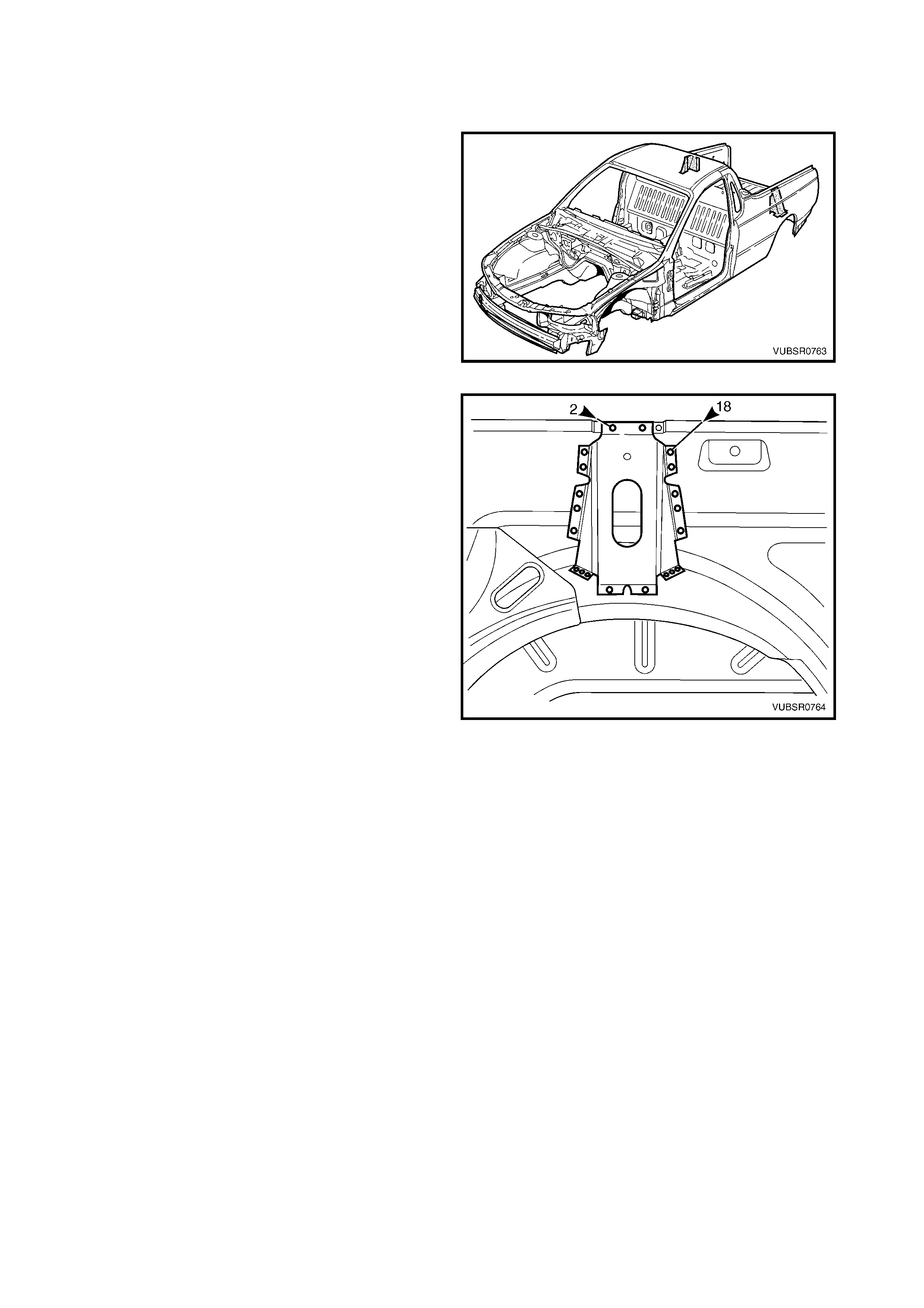
The shaded components in Figure 7C-1 are those
dealt with in this Section.
The components and assemblies shown in Figure 7C-
2 are the parts serviced for MY 2003 VY Series Utility
vehicles which form the basis of the repair procedures
in this Section. For a detailed view of the body
components, refer to Section 3C BODY
CONSTRUCTION - UTILITY.
NOTE: Always refer to your Authorised Retailer for
spare parts availability configurations.
IMPORTANT: Cavity foam may be used within
the hinge, and centre pillars. Care needs to be taken
when repairing the vehicle in these areas, refer to
Section 2, 10. CAVITY FOAM prior to beginning any
work for further information. Figure 7C-1
Figure 7C-2

Legend
1. Hinge Pillar Trim Panel Bracket
2. Hinge Pillar Inner Panel Assembly
3. Hinge Pillar Upper Reinforcement
4. Fender Upper Rear Bracket
5. Fender Lower Rear Bracket
6. Fender Rear Bracket
7. Underbody Jacking Locator
8. Front Door Striker Anchor Plate
9. Door Opening Frame Assembly
10. Quarter Panel Inner Extension
11. Side Inner Upper Front Panel
12. Seatbelt Guide Anchor Plate Assembly
13. Fuel Filler Pipe Housing
14. Rear Wheelhouse Outer Extension
15. Front Inner Side Panel Cover
16. Load Floor Panel Outer Extension
17. Rear Wheelhouse Inner Panel
18. Cargo Tie-down Bracket
19. Rear Inner Side Panel Cover
20. Side Inner Upper Panel
21. Endgate Striker Anchor Plate Retainer
22. Quarter Lower Rear Panel
23. Quarter Inner Lower Rear Extension
24. Cargo Tie-down Bracket Anchor Plate Assembly
25. Rear Wheelhouse Bracket
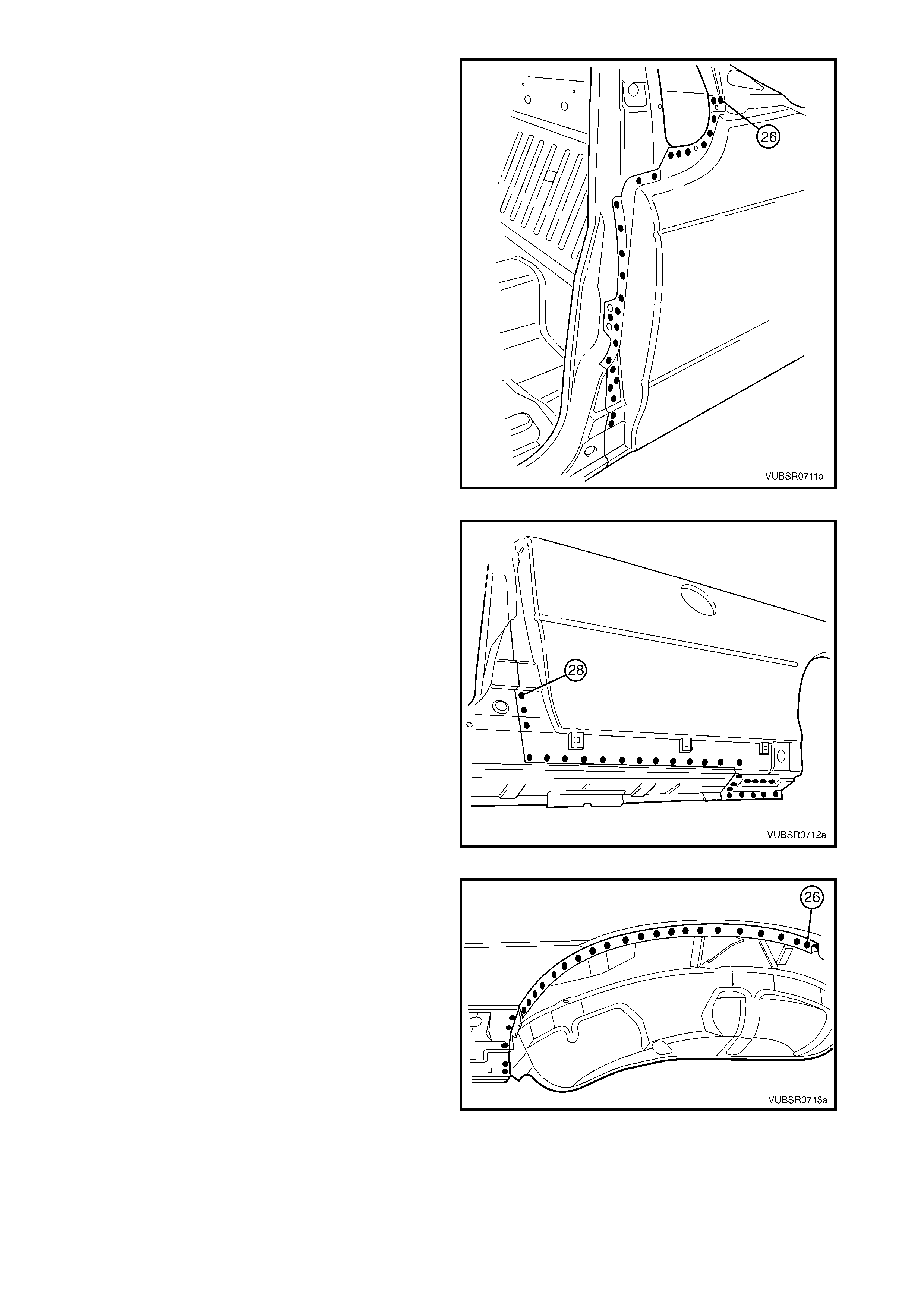
26. Load Floor Panel Outer Reinforcement
27. Quarter Inner & Rear Wheelhouse Brace
28. Quarter Panel Inner Assembly
29. Quarter Panel Upper Extension
30. Quarter Panel Extension
31. Rear Quarter Panel
32. Quarter Outer Lower Rear Panel
NOTE: The door opening frame assembly includes parts 3, 4, 5, 6, 7 and 8.
2. SERVICE OPERATIONS
2.1 REAR QUARTER P ANEL – REPLACE
NOTE: The rear body wiring harness is routed behind
the right-hand quarter panel; take care not to damage
or burn the harness.
CAUTION: The fuel tank is located under the rear
floor - front. To av oid the possibility of fire, remove
the fuel tank and plug all lines when grinding,
cutting or welding.
REMOVE
1. Remove the adjacent bolt-on panels and
components as described in the appropriate
Section of the MY 2003 VY & V2 Series II Service
Information.
2. Remove the rear and quarter windows, refer to
Section 1A6 STATIONARY WINDOWS in the
MY 2003 VY & V2 Series II Service Information.
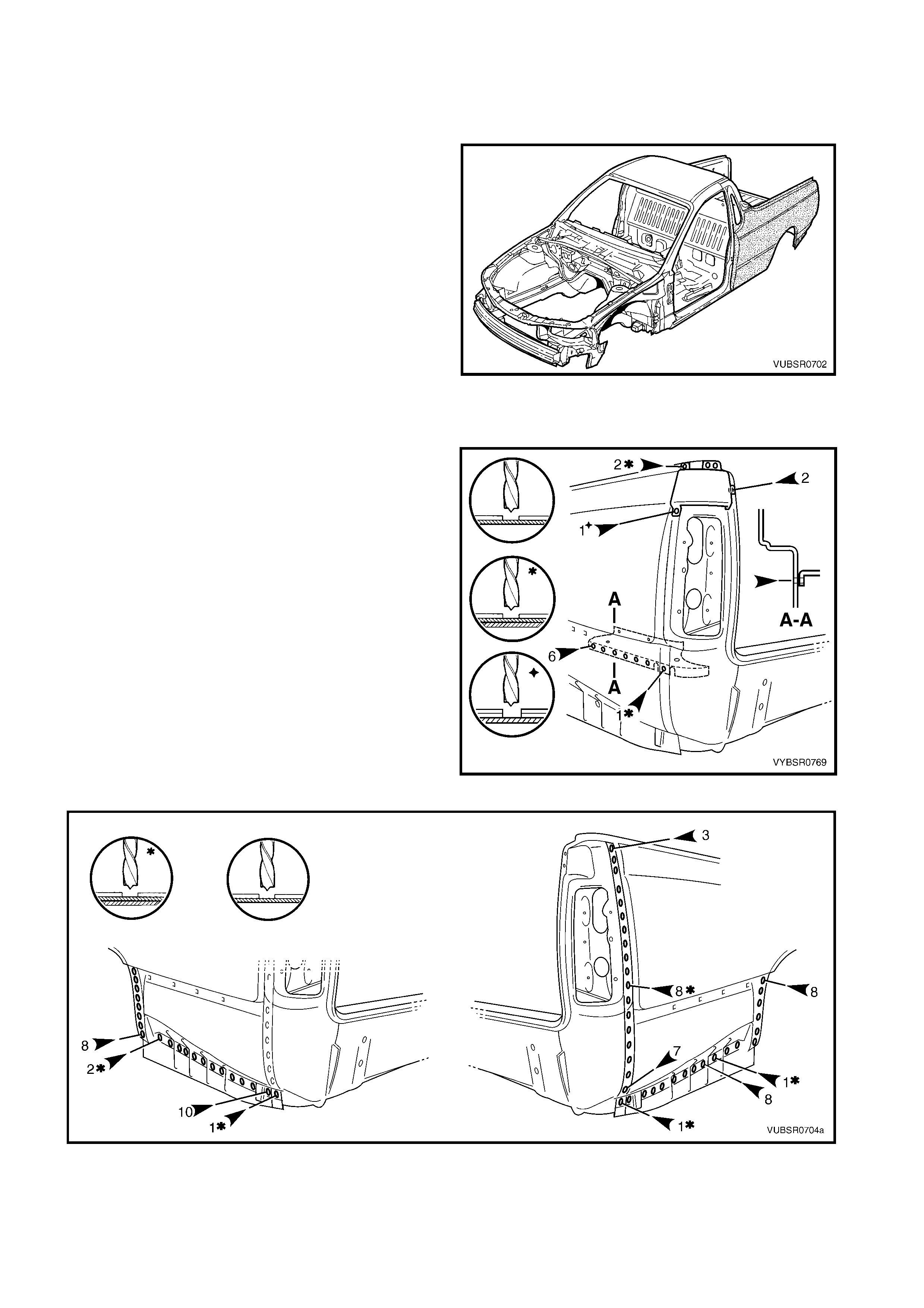
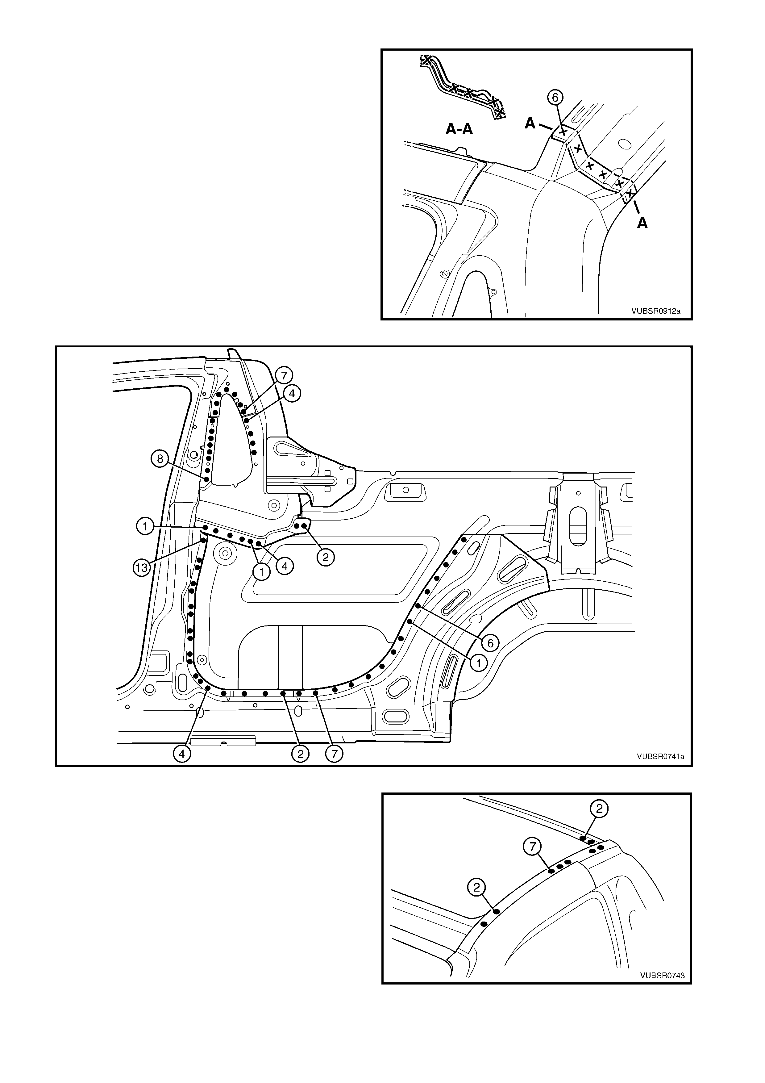
Figure 7C-3
3. To access the spot welds underneath, the quarter
panel upper extension will require removal. Spot
cut:
- two welds attaching it to the quarter panel
extension,
- two welds attaching it to the quarter panel
extension and side inner upper panel,
- one weld attaching it and the rear quarter panel
to the quarter panel extension.
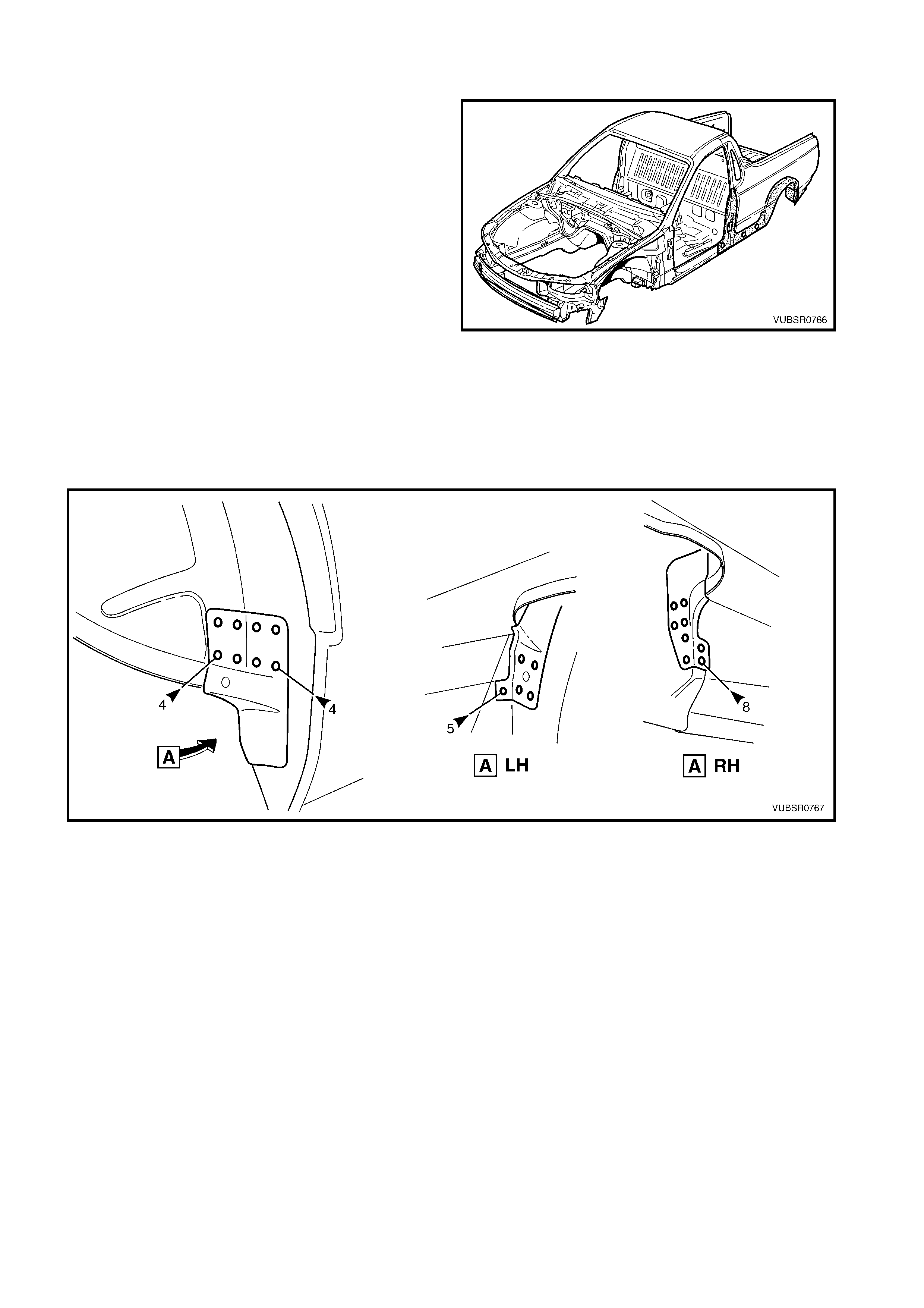
4. Spot cut the six welds attaching the rear quarter
panel to the quarter outer lower rear panel.
5. Spot cut the weld attaching the rear quarter panel
and quarter panel extension to the quarter outer
lower rear panel.
6. Spot cut the welds attaching the rear quarter panel
as shown in Figure 7C-5. Note differences
between left-hand and right-hand sides.
Figure 7C-4
Figure 7C-5
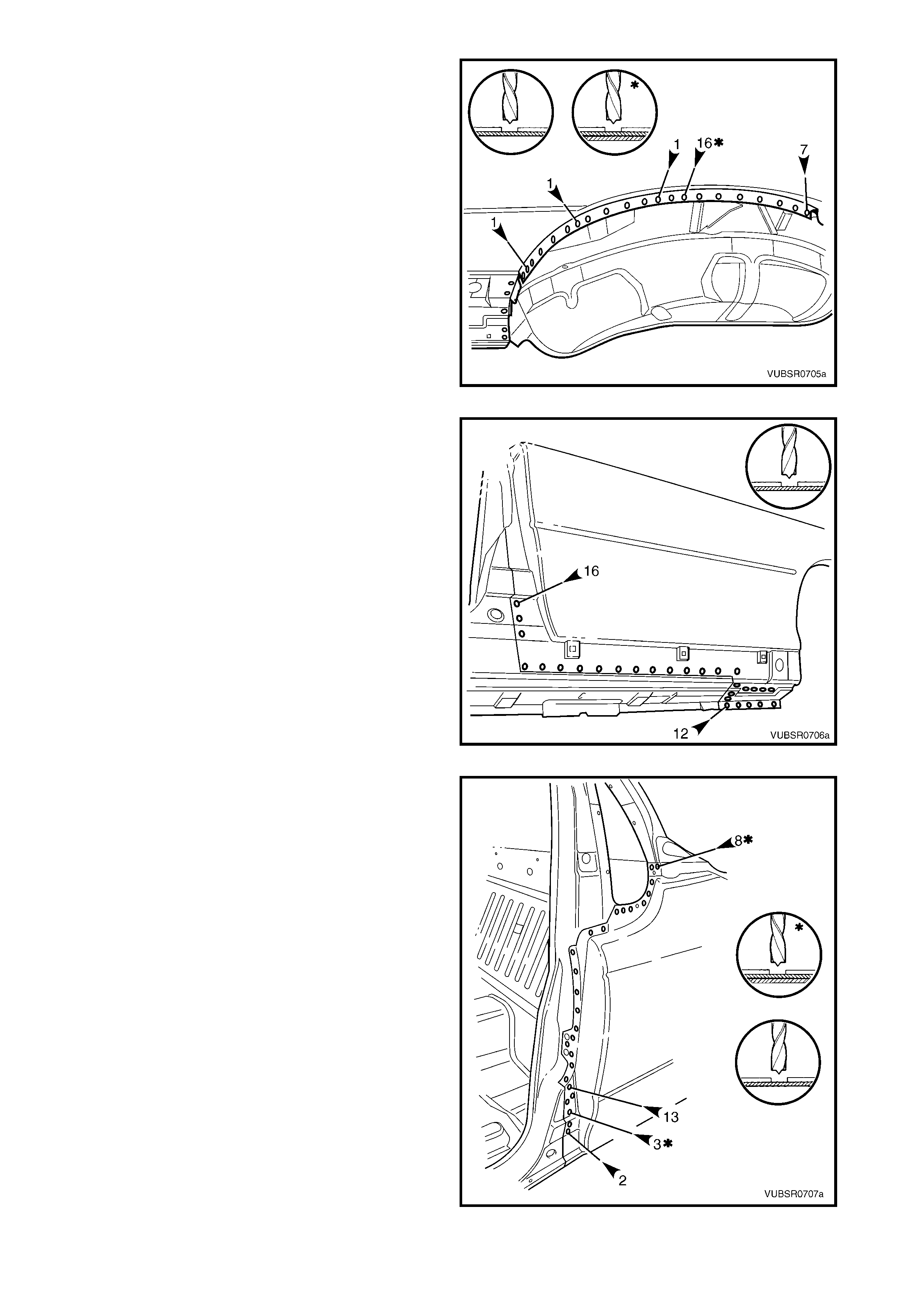
7. Spot cut the welds around the wheel arch opening
attaching the rear quarter panel to the door
opening frame assembly and quarter panel inner
assembly.
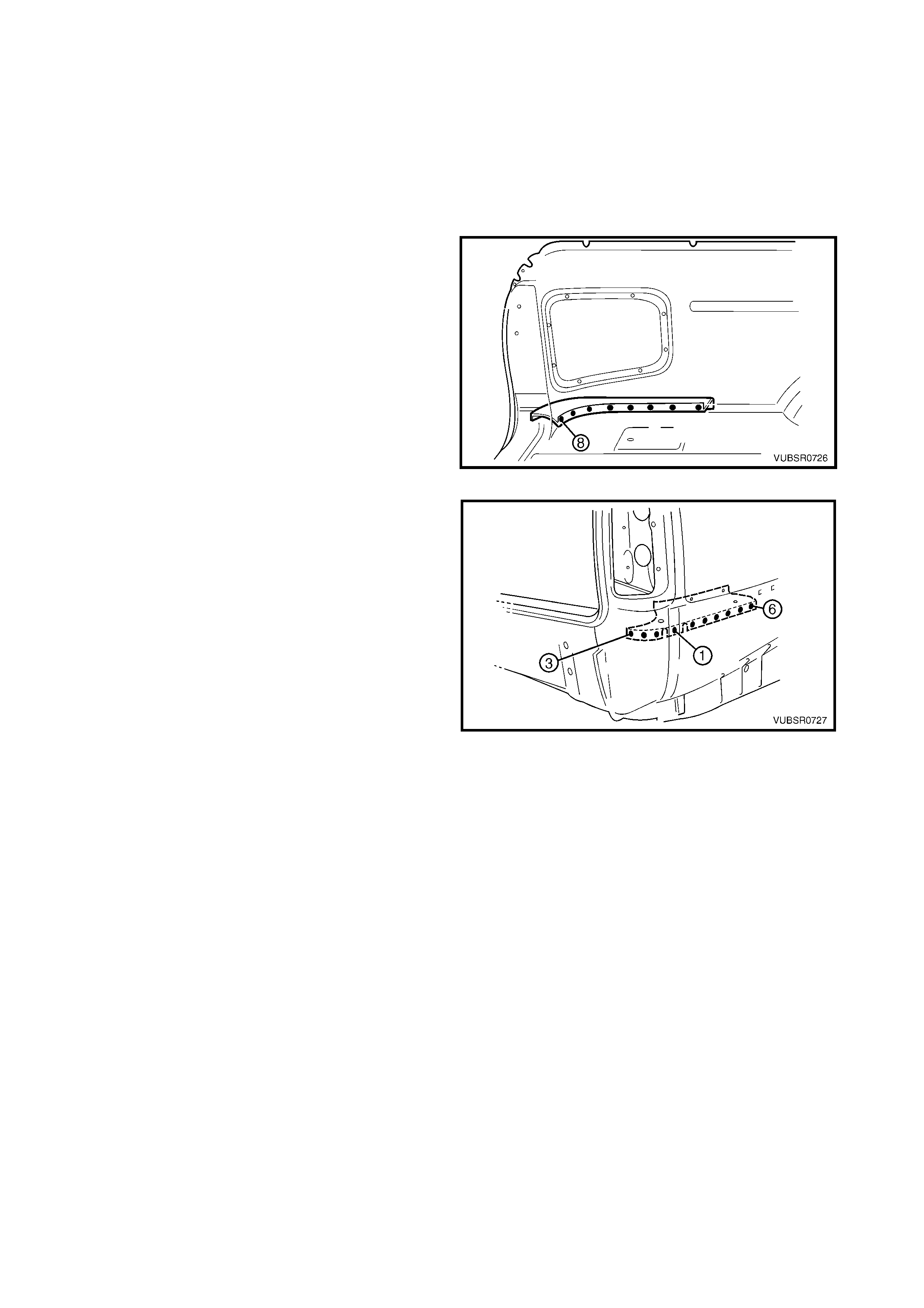
Figure 7C-6
8. Spot cut the welds attaching the rear quarter panel
to the door opening frame assembly.
Figure 7C-7
9. Spot cut the welds attaching the rear quarter panel
to the door opening frame assembly.
10. Spot cut the welds attaching the rear quarter panel
to the side inner upper panel assembly and lock
pillar outer panel brace, refer to Figure 7C-9.
11. Remove the rear quarter panel and repair any
damage to adjacent parts as required.
NOTE: Acrylic spot weld sealer is used in many of the
joints which may require prising apart.
12. Check and rectify the alignment of the body as
required, refer to 3. BODY DIMENSIONS in
Section 3C.
Figure 7C-8
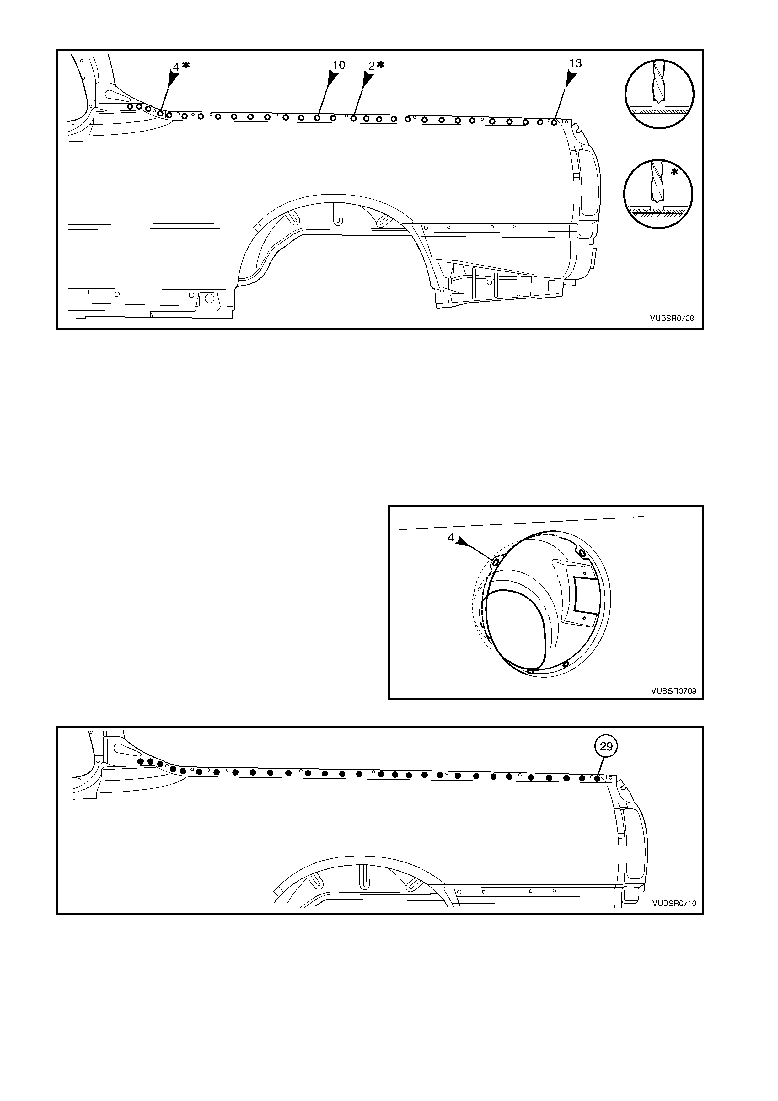
Figure 7C-9
REPLACE
NOTE 1: Spot welding is the preferred method for attaching of panels and should be used whenever possible.
Where the spot welding equipment will not access the required weld position, a plug weld should be performed.
NOTE 2: The same number and position of s pot welds ( or plug welds) s hould be used when replacing the panel,
as was used during manufacture, in order to maintain the original structural strength of the vehicle.
1. As required, mark the new panel with drilling locations in preparation for plug welding. Drill holes as required.
2. Prepare all mating surfaces and treat with Weld Through Primer (Item 1) as required, refer to
5. BODY SEALING, ADHESIVES & DEADENERS in Section 3C.
3. For the right-hand side, if required spot or plug
weld the fuel filler pipe housing to the rear quarter
panel in four places.
4. Apply Acrylic Spot Weld Sealer (Item 2), refer to
5. BODY SEALING, ADHESIVES & DEADENERS
in Section 3C.
5. Clamp the panel into position ensuring correct
alignment with the door and the body structure.
6. Spot or plug weld the rear quar ter panel to the s ide
inner upper panel and lock pillar outer panel brac e,
refer to Figure 7C-11.
Figure 7C-10
Figure 7C-11
7. Spot or plug weld the rear quarter panel to the
door opening frame assembly .
Figure 7C-12
8. Spot or plug weld the rear quarter panel to the
door opening frame assembly .
Figure 7C-13
9. Spot or plug weld the rear quarter panel to the
door opening frame assembly and quarter panel
inner assembly around the wheel arch opening.
10. Spot or plug weld the rear quarter panel as shown
in Figure 7C- 15. Note diff erences between the left-
hand and right-hand sides.
Figure 7C-14
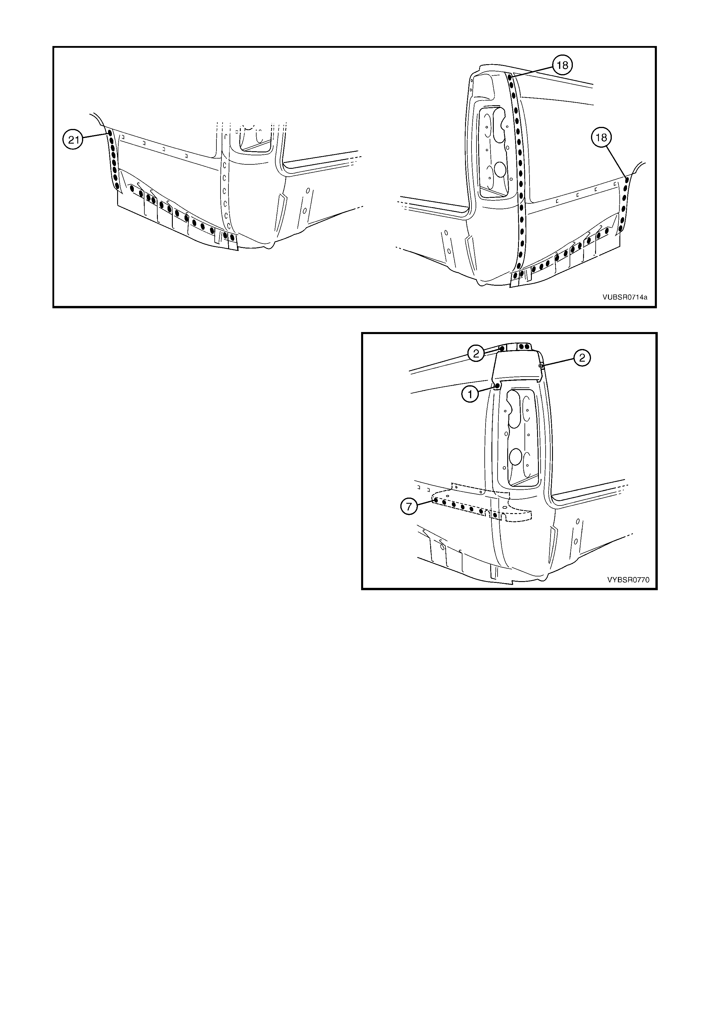
Figure 7C-15
11. Spot or plug weld the rear quarter panel to the
quarter outer lower rear panel, seven places.
12. Install and spot or plug weld the quarter panel
upper extension:
- to the quarter panel extension, two places,
- to the quarter panel extension and side inner
upper panel, two places,
- to the rear quarter panel and quarter panel
extension, one place.
13. Refinish and paint panels and other components
as required. Refer to Section 3, 1.3 PAINT
REFINISHING.
14. Apply Joint Sealer (Item 3) as required. Refer to
5. BODY SEALING, ADHESIVES & DEADENERS
in Section 3C.
15. Apply Cavity Wax (Item 8) as requir ed to the inside
of any box sections or areas inaccessible to paint,
refer to 6. CAVITY WAX in Section 3C.
16. Apply Spray-on Deadener (Item 7) where
applicable, refer to 5. BODY SEALING,
ADHESIVES & DEADENERS in Section 3C.
17. Replace the rear and quarter windows, refer to
Section 1A6 STATIONARY WINDOWS in the
MY 2003 VY & V2 Series II Service Information.
18. Install the remaining components as described in
the appropriate Section of the MY 2003 VY & V2
Series II Service Information.
Figure 7C-16
2.2 QUARTER PANEL EXTENSION – REPLACE
REMOVE
1. Remove the adjacent bolt-on panels and
components as described in the appropriate
Section of the MY 2003 VY & V2 Series II Service
Information.
Figure 7C-17
2. To access the spot welds underneath, the quarter
panel upper extension piece will require removal.
Spot cut:
- two welds attaching it and the quarter panel
extension to the side inner upper panel,
- one weld attaching it and the rear quarter panel
to the quarter panel extension,
- two welds attaching it to the quarter panel
extension.
3. Spot cut the three welds attaching the quarter
panel extension to the quarter outer lower rear
panel.
4. Spot cut the weld attaching the rear quarter panel
and quarter panel extension to the quarter outer
lower rear panel.
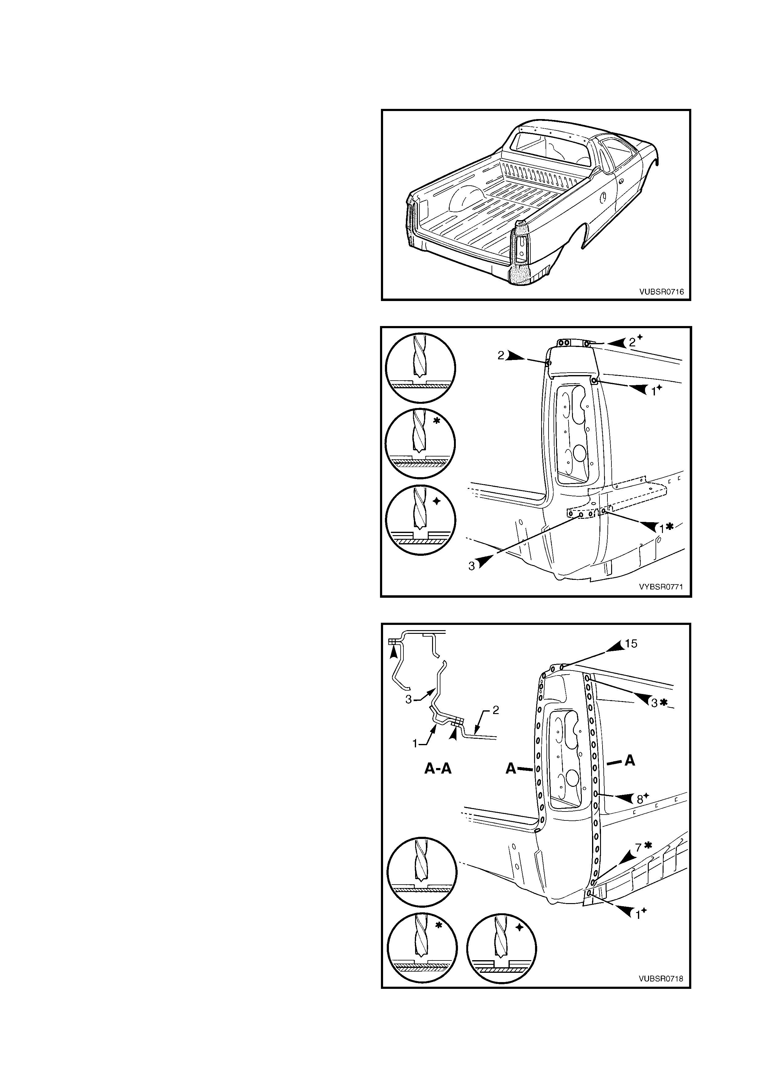
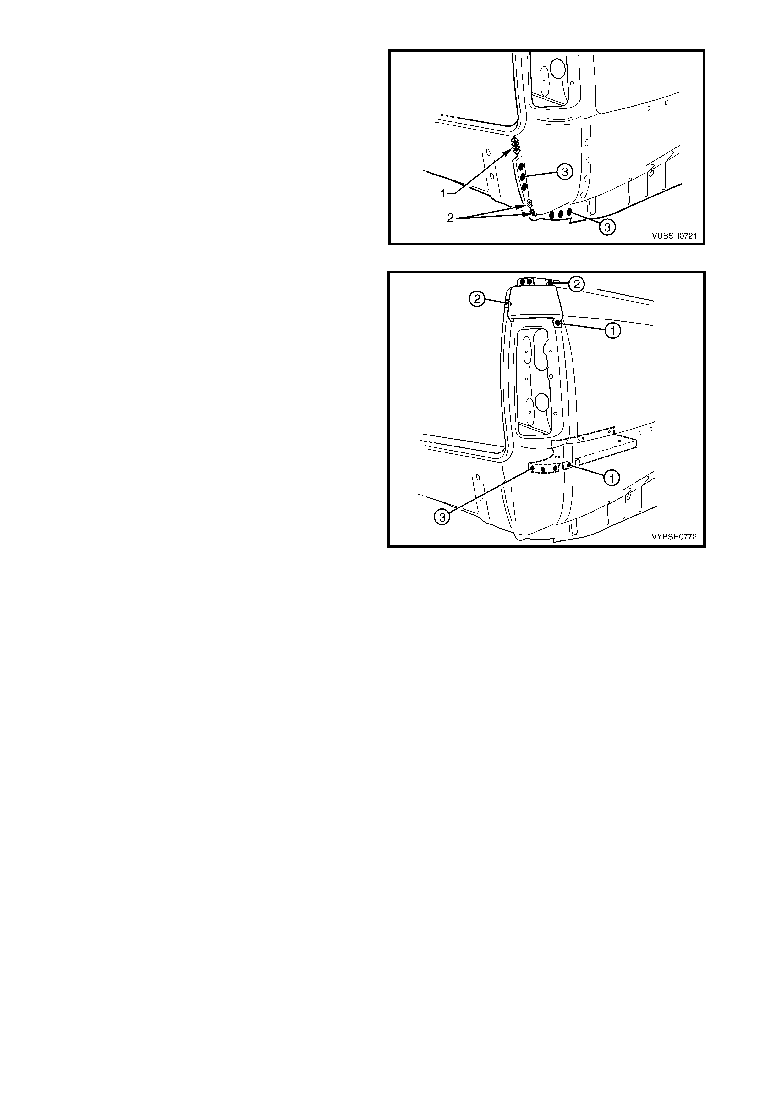
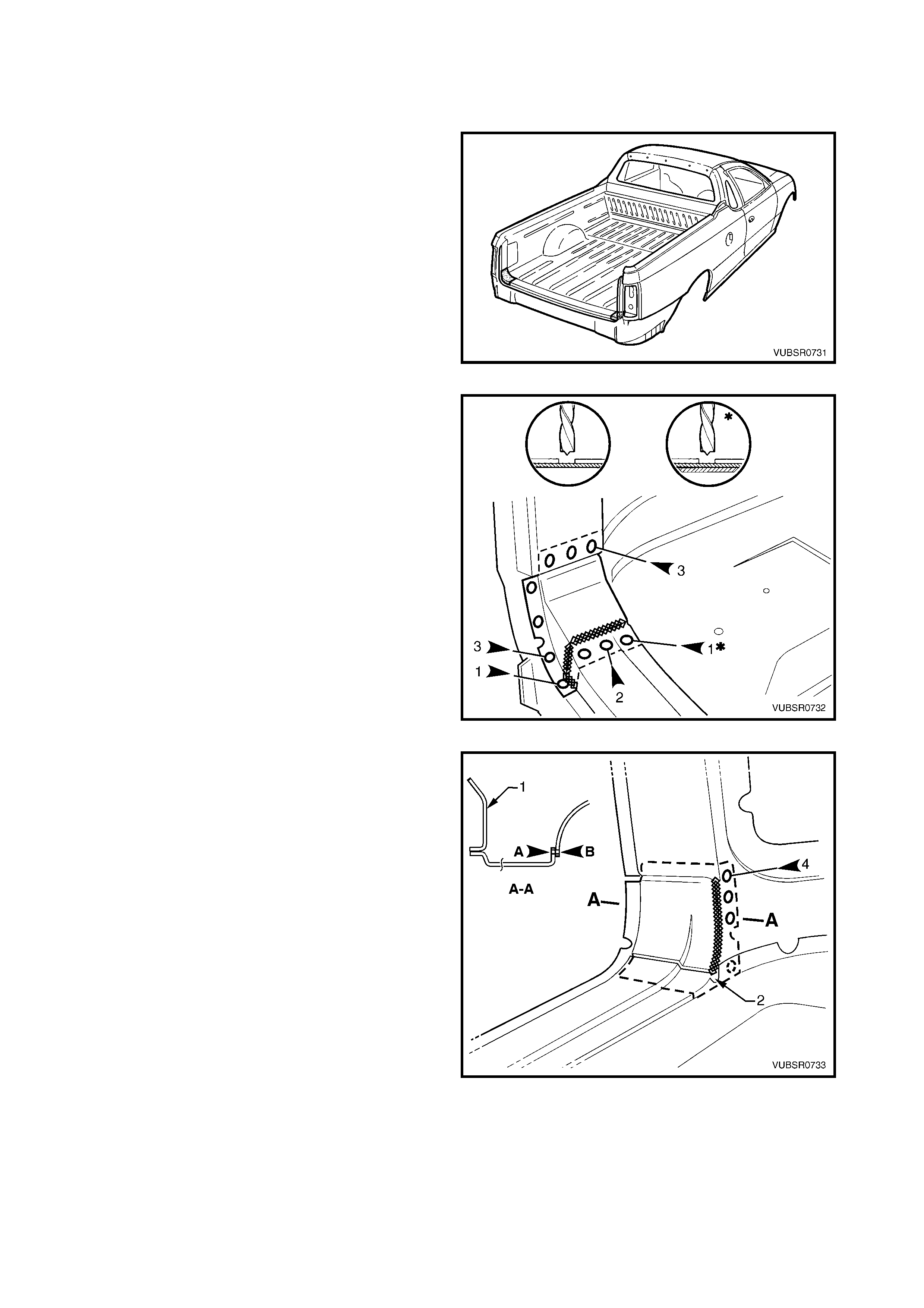
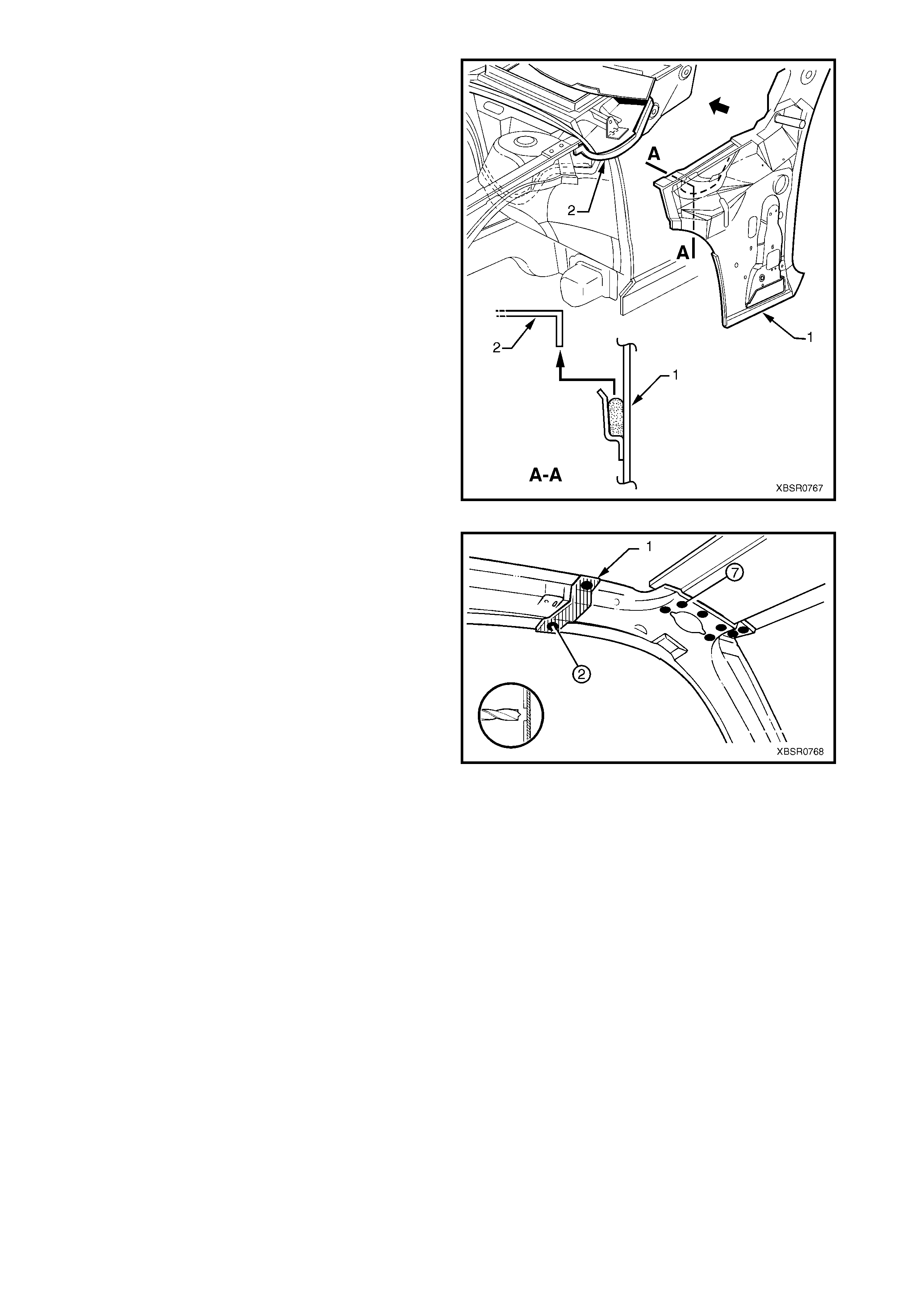
Figure 7C-18
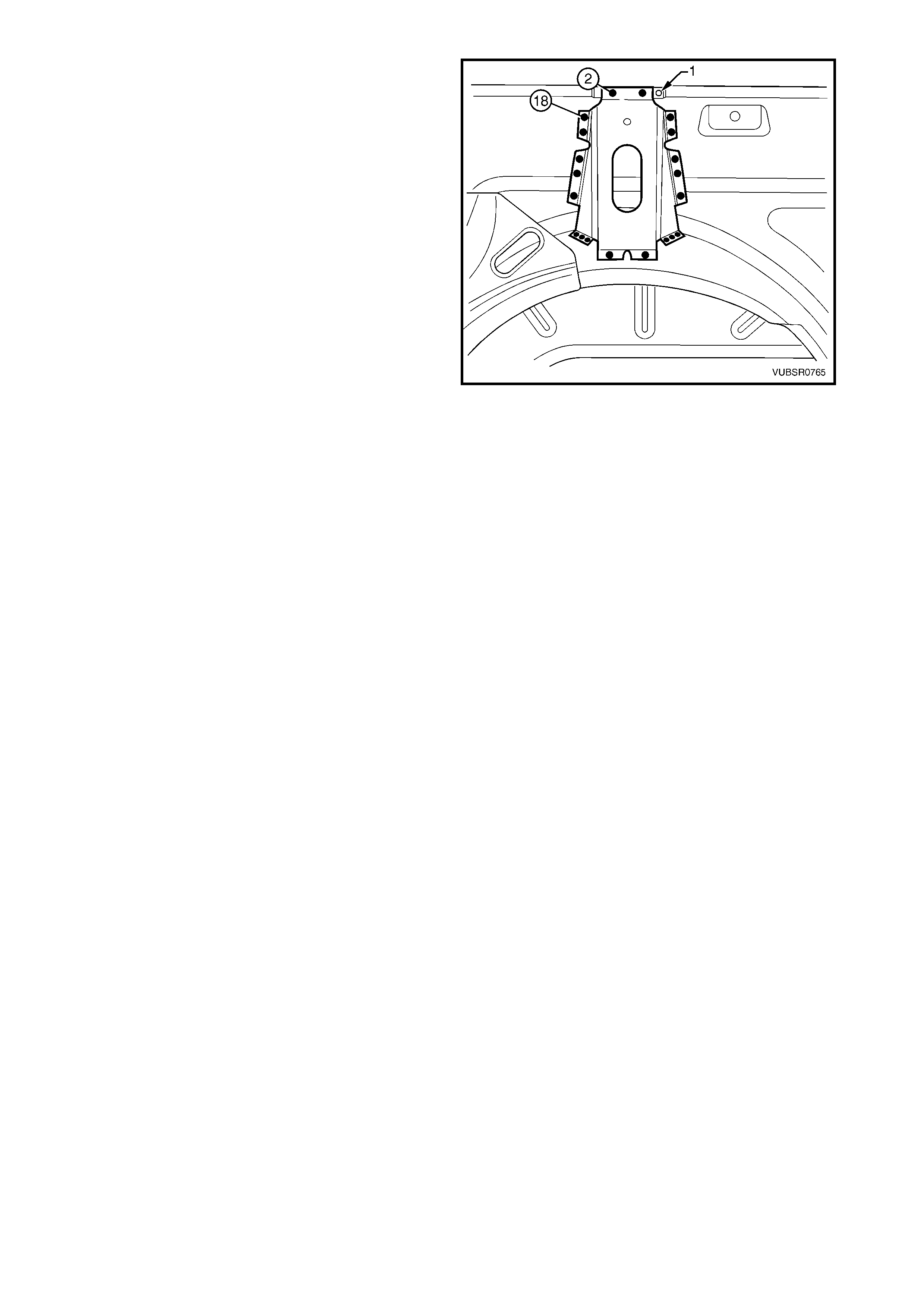
5. Spot cut the 8 welds attaching the quarter panel
extension (1) between the rear quarter panel (2)
and quarter inner lower rear extension (3), refer to
Section A-A.
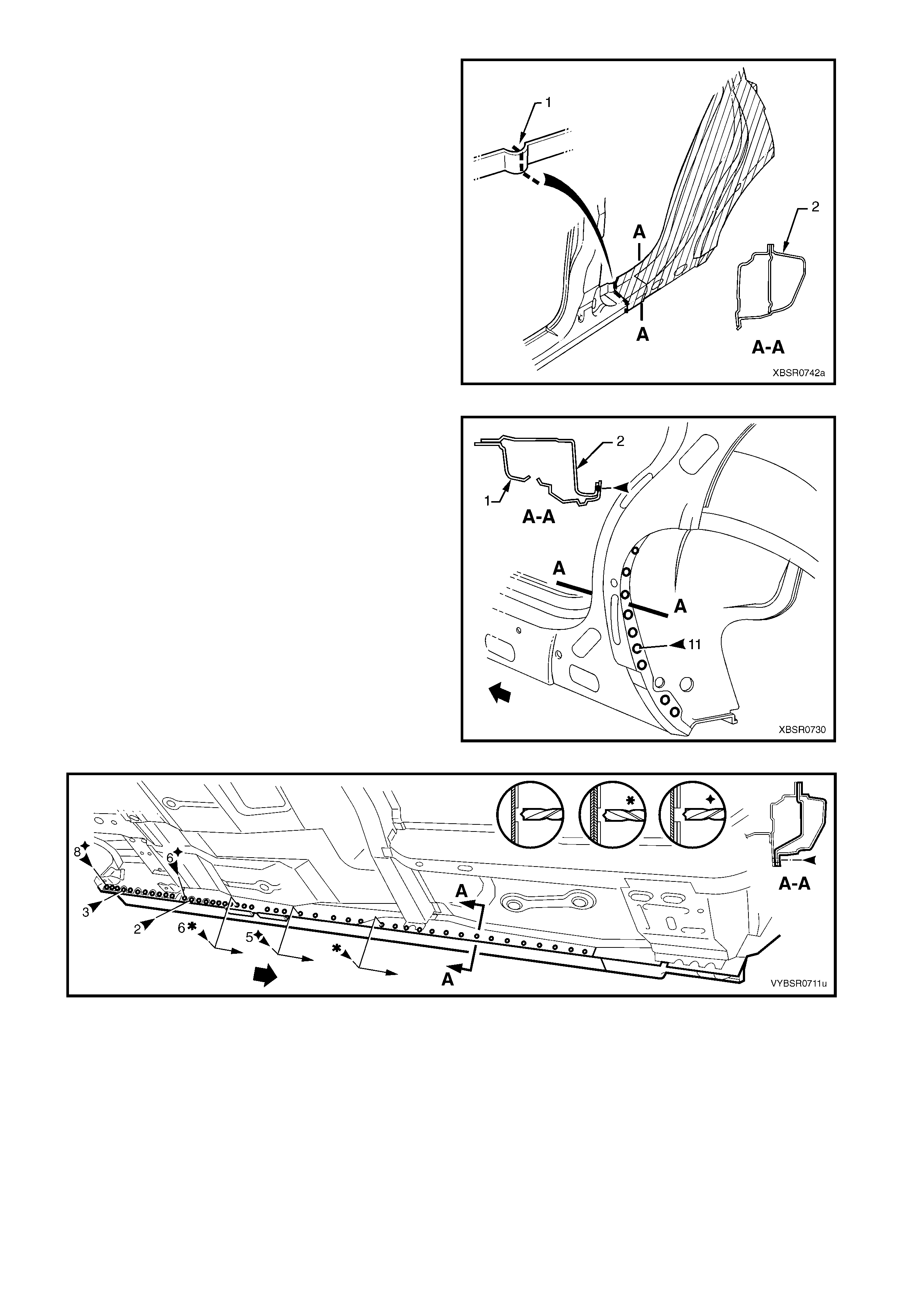
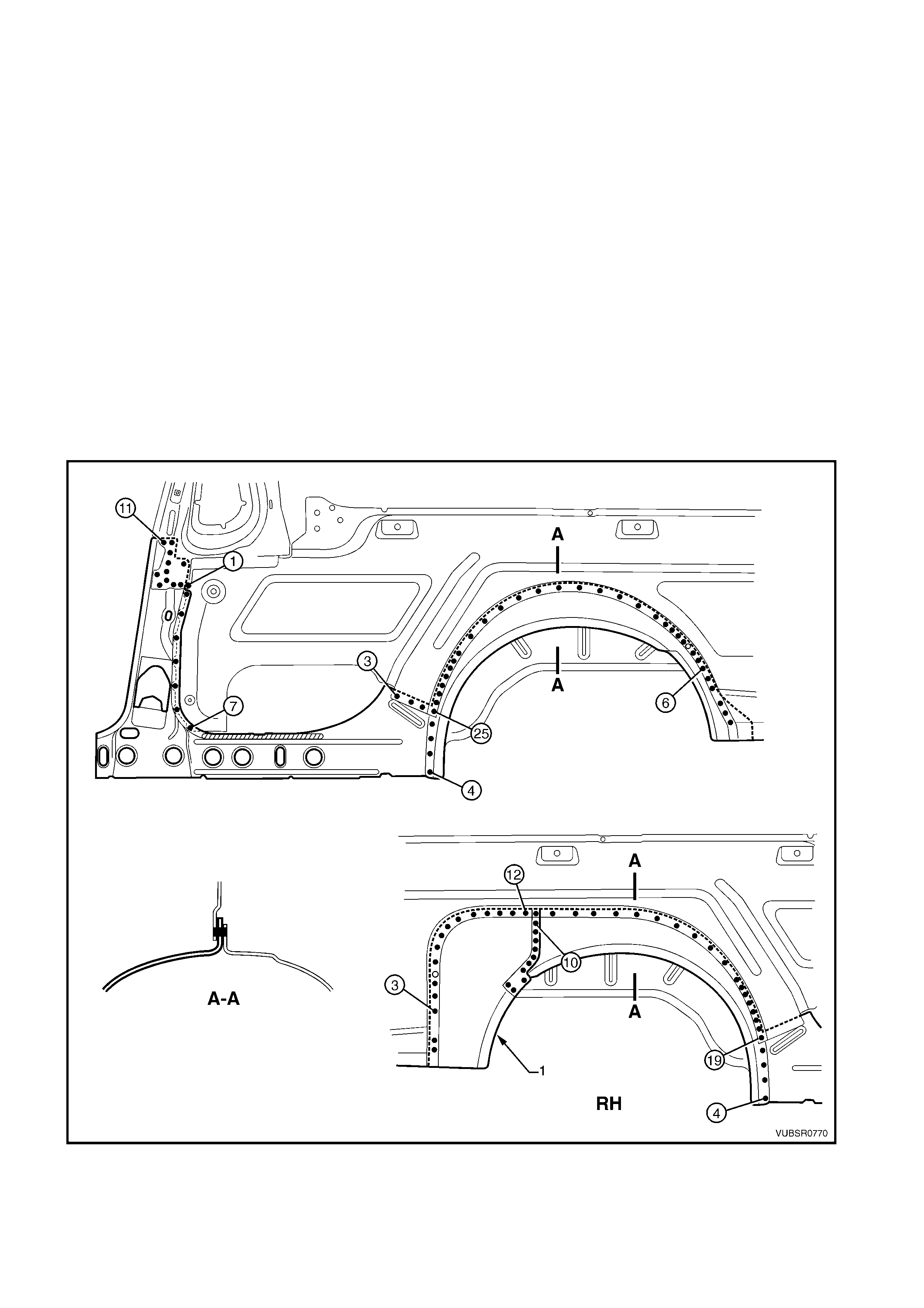
6. Spot cut the 10 welds attaching the quarter panel
extension to the rear quarter panel.
7. Spot cut the weld attaching the rear quarter panel
and quarter panel extension to the side inner upper
panel.
8. Spot cut the 15 welds attaching the quarter panel
extension to the side inner upper panel.
Figure 7C-19
9. Spot cut the 3 welds attaching the quarter panel
extension to the side inner upper panel.
10. Spot cut the 3 welds attaching the quarter panel
extension to the rear end lower panel.
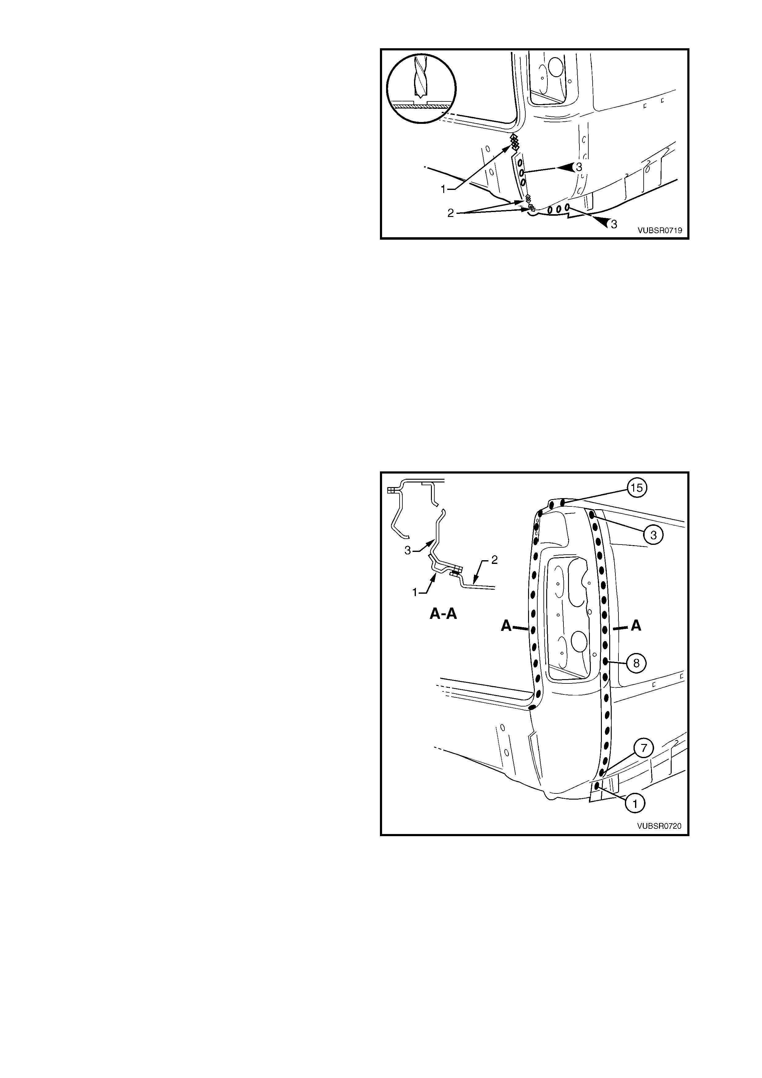
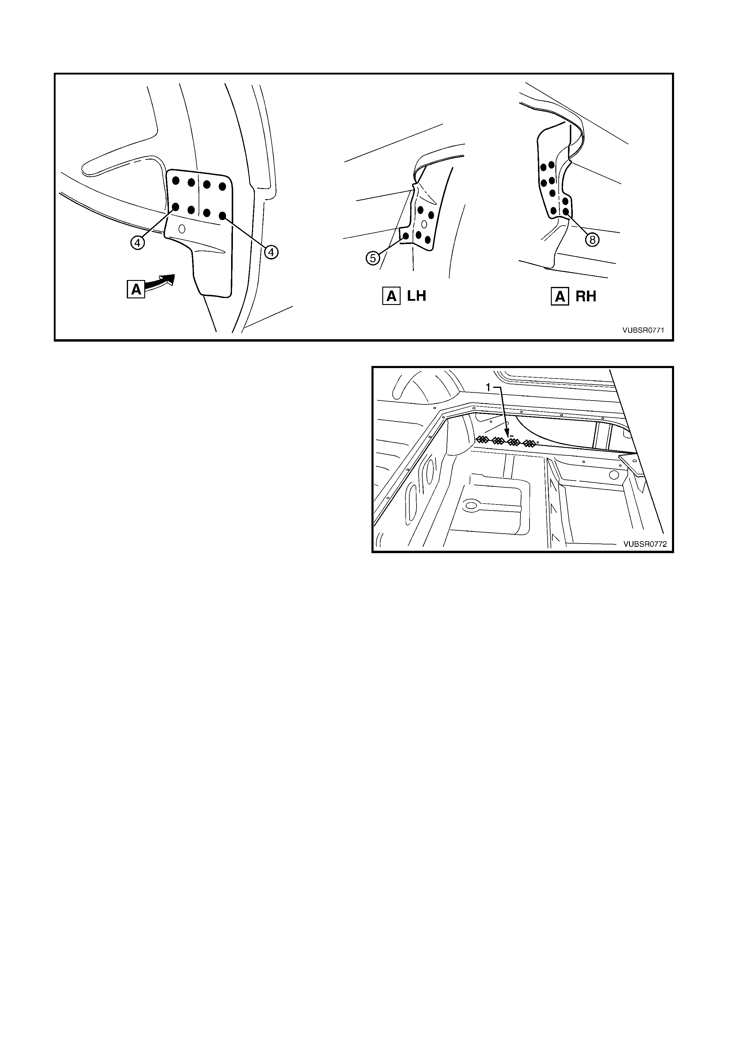
11. Grind off the MIG weld (1) and two MIG welds (2)
attaching the quarter panel extension to the rear
end lower panel.
12. Remove the quarter panel extension and repair
any damage to adjacent parts as required.
NOTE: Acrylic spot weld sealer is used between the
rear quarter panel and quarter panel extension which
may require prising apart.
13. Check and rectify the alignment of the body as
required, refer to 3. BODY DIMENSIONS in
Section 3C.
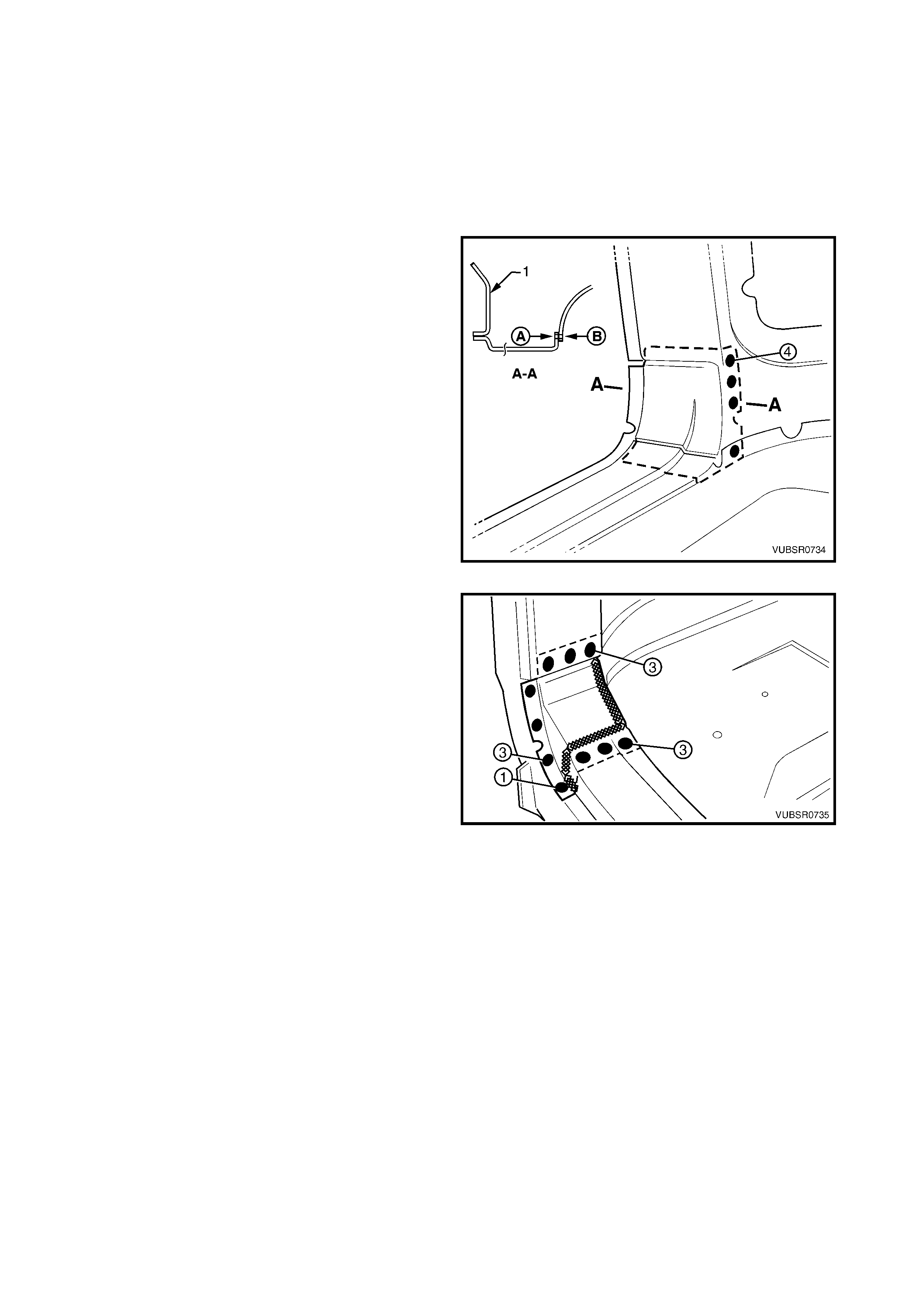
Figure 7C-20
REPLACE
NOTE 1: Spot welding is the preferred method for attaching of panels and should be used whenever possible.
Where the spot welding equipment will not access the required weld position, a plug weld should be performed.
NOTE 2: The same number and position of s pot welds ( or plug welds) s hould be used when replacing the panel,
as was used during manufacture, in order to maintain the original structural strength of the vehicle.
1. As required, mark the new panel with drilling locations in preparation for plug welding. Drill holes as required.
2. Prepare all mating surfaces and treat with Weld Through Primer (Item 1) as required, refer to
5. BODY SEALING, ADHESIVES & DEADENERS in Section 3C.
3. Apply Acrylic Spot Weld Sealer (Item 2), refer to 5. BODY SEALING, ADHESIVES & DEADENERS in
Section 3C.
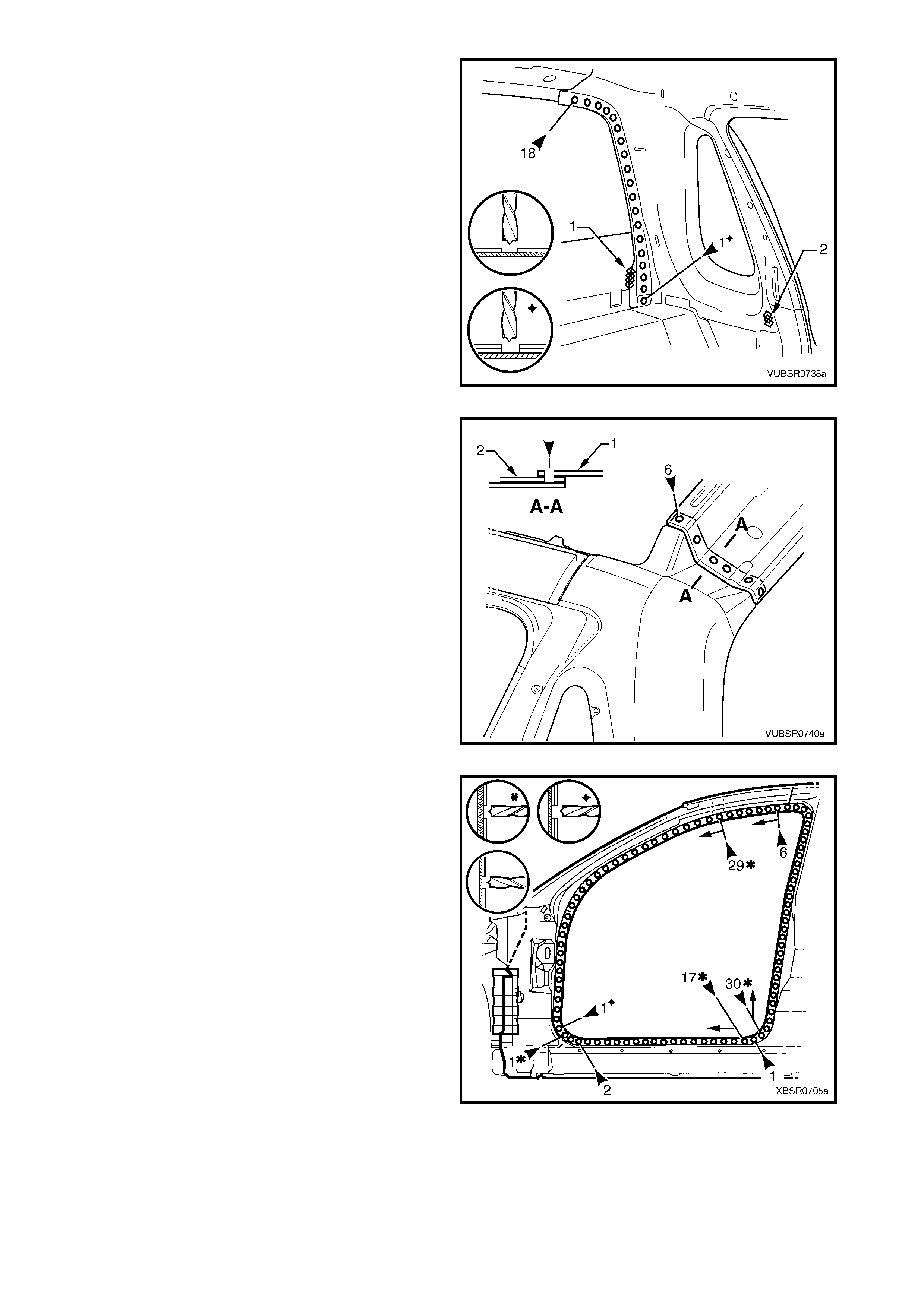
4. Clamp the panel into position, fitting the quarter
panel extension flange (1) between the rear
quarter panel (2) and quarter inner lower rear
extension (3), refer to Section A-A.
5. Test fit the tail lamp and check for correct
alignment with the endgate and the body structure.
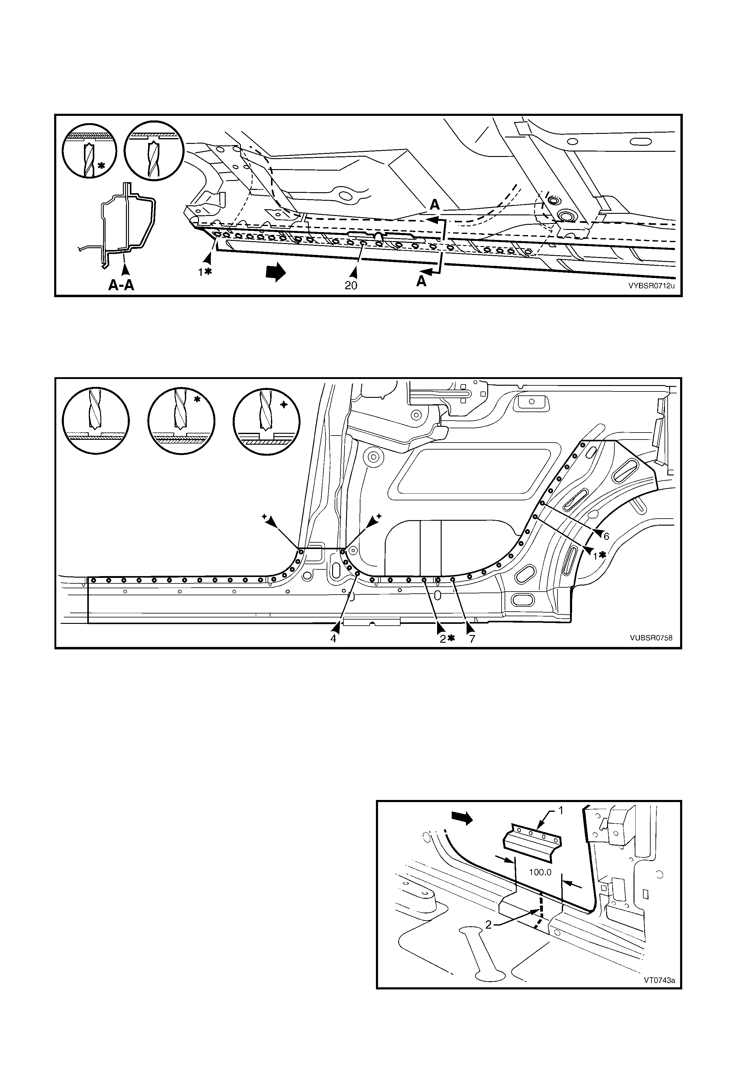
6. Spot or plug weld 8 places, the quarter panel
extension (1), rear quarter panel (2) and quarter
inner lower rear extension (3), refer to Section A-A.
NOTE: T ake care when welding the rear quarter panel
to avoid heat distortion.
7. Spot or plug weld 10 places, the rear quarter panel
to the quarter panel extension.
8. Spot or plug weld 1 place, the rear quarter panel
and quarter panel extension to the side inner
upper panel.
9. Spot or plug weld the quarter panel extension to
the side inner upper panel, 15 places.
Figure 7C-21
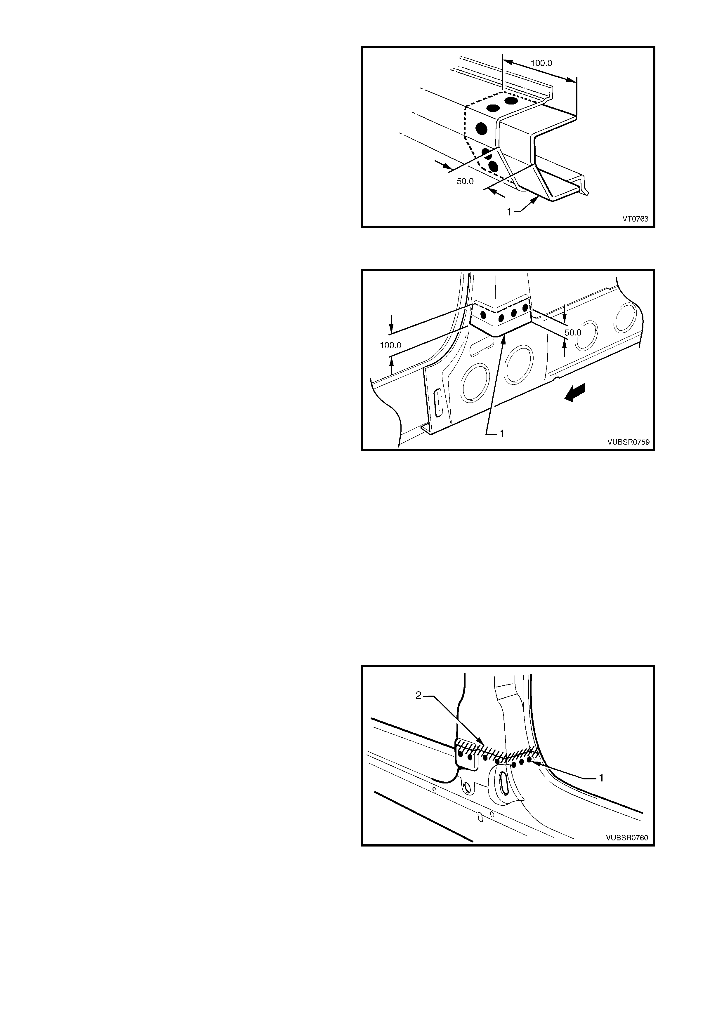
10. Spot or plug weld 3 places, the quarter panel
extension to the side inner upper panel.
11. Spot or plug weld 3 places, the quarter panel
extension to the rear end lower panel.
12. MIG weld one place 55 mm (1) and two places 30
mm (2), the quarter panel extension to the rear
end lower panel.
Figure 7C-22
13. Spot or plug weld three places, the quarter panel
extension to the quarter outer lower rear panel.
14. Spot or plug weld 1 place, the rear quarter panel
and quarter panel extension to the quarter outer
lower rear panel.
15. Install and spot or plug weld the quarter panel
upper extension:
- and the quar ter panel extens ion to the s ide inner
upper panel two places,
- and the rear quarter panel to the quarter panel
extension one place,
- to the quarter panel extension two places.
16. Refinish and paint panels and other components
as required. Refer to Section 3, 1.3 PAINT
REFINISHING.
17. Apply Joint Sealer (Item 3) as required. Refer to
5. BODY SEALING, ADHESIVES & DEADENERS
in Section 3C.
18. Apply Cavity Wax (Item 8) as requir ed to the inside
of any box sections or areas inaccessible to paint,
refer to 6. CAVITY WAX in Section 3C.
19. Install the remaining components as described in
the appropriate Section of the MY 2003 VY & V2
Series II Service Information.
Figure 7C-23
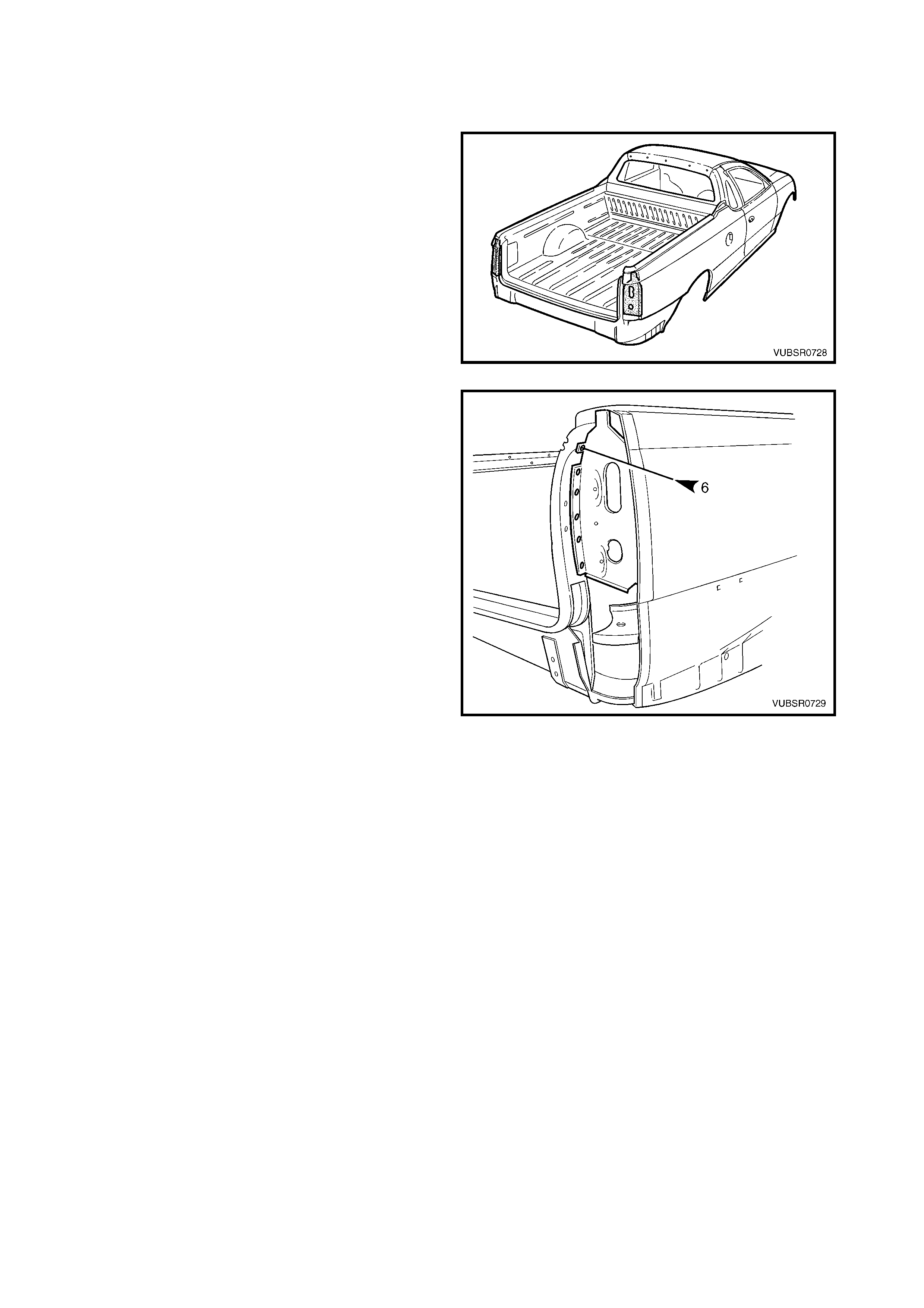
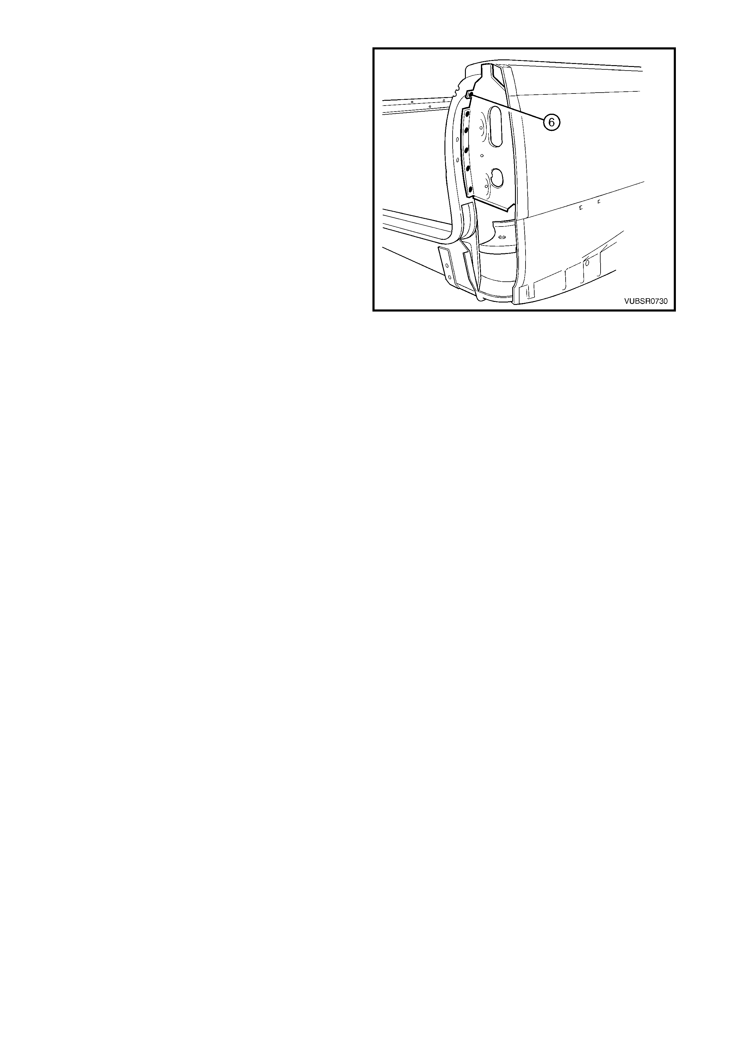
2.3 QUARTE R INNE R LOWER REAR EX TENSION – REPLACE
REMOVE
1. Remove the adjacent bolt-on panels and
components as described in the appropriate
Section of the MY 2003 VY & V2 Series II Service
Information.
2. Rem ove the quarter panel extension as previously
described.
Figure 7C-24
3. Spot cut the welds attaching the quarter inner
lower rear extension to the side inner upper panel.
4. Remove the quarter inner lower rear extension and
repair any damage to adjacent parts as required.
Figure 7C-25
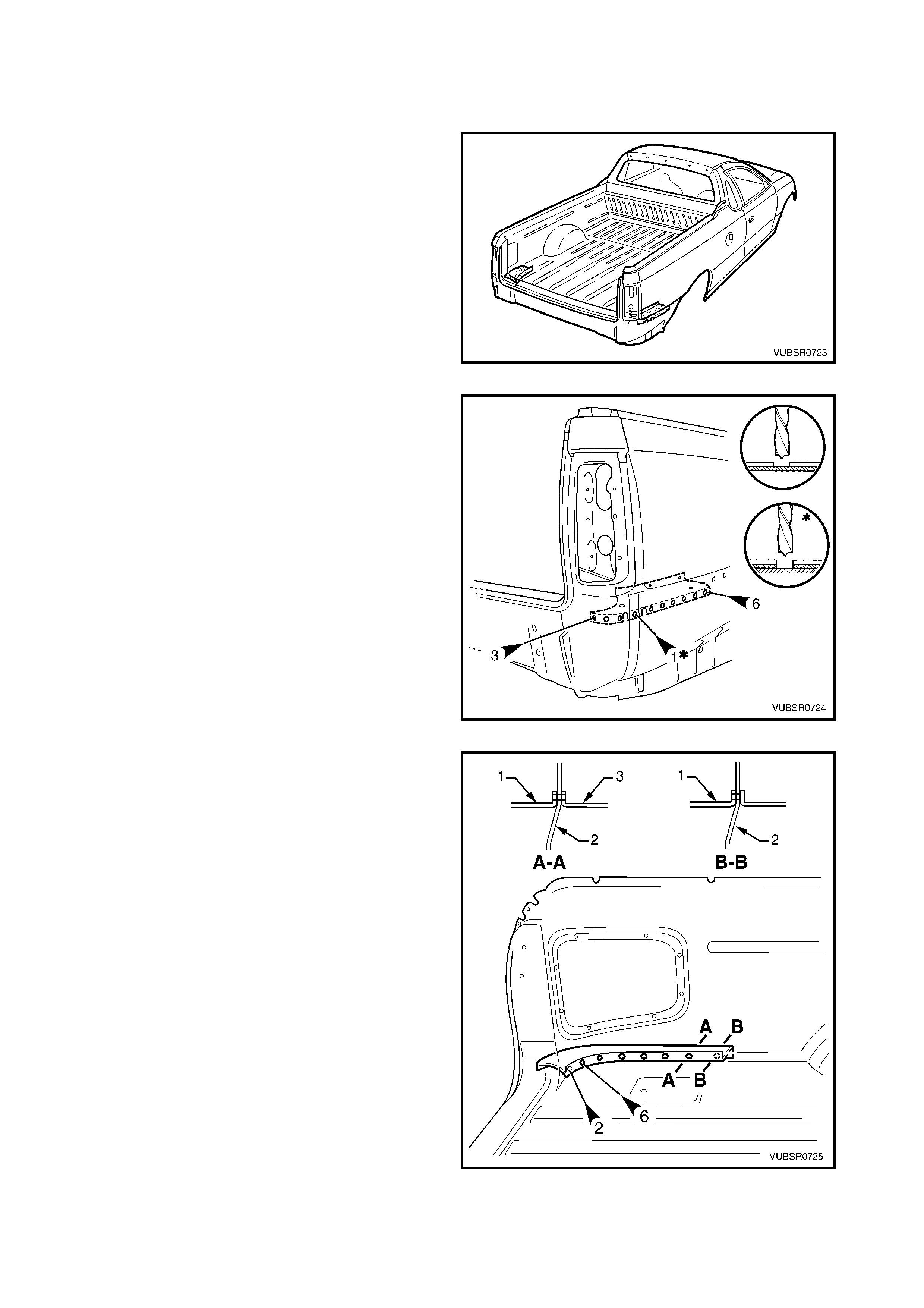
REPLACE
NOTE 1: Spot welding is the preferred method for attaching of panels and should be used whenever possible.
Where the spot welding equipment will not access the required weld position, a plug weld should be performed.
NOTE 2: The s ame number and pos ition of spot welds ( or plug welds) s hould be used when replac ing the panel,
as was used during manufacture, in order to maintain the original structural strength of the vehicle.
1. As required, mark the new panel with drilling locations in preparation for plug welding. Drill holes as required.
2. Prepare all mating surfaces and treat with Weld Through Primer (Item 1) as required, refer to
5. BODY SEALING, ADHESIVES & DEADENERS in Section 3C.
3. Clamp in position and spot or plug weld the quarter
inner lower rear extension to the side inner upper
panel.
4. Replace the quarter panel extension as previously
described.
5. Replace any other removed panels as required.
6. Refinish and paint panels and other components
as required. Refer to Section 3, 1.3 PAINT
REFINISHING.
7. Apply Joint Sealer (Item 3) as required. Refer to
5. BODY SEALING, ADHESIVES & DEADENERS
in Section 3C.
8. Apply Cavity Wax (Item 8) as requir ed to the inside
of any box sections or areas inaccessible to paint,
refer to 6. CAVITY WAX in Section 3C.
9. Install the remaining components as described in
the appropriate Section of the MY 2003 VY & V2
Series II Service Information.
Figure 7C-26
2.4 QUARTER OUTER LOWER REAR PANEL – REPLACE
REMOVE
1. Remove the adjacent bolt-on panels and
components as described in the appropriate
Section of the MY 2003 VY & V2 Series II Service
Information.
2. Remove the adjacent panels as required, refer to
the appropriate procedure in this Section.
Figure 7C-27
3. Spot cut the welds attaching the rear quarter panel
and quarter panel extension to the quarter outer
lower rear panel.
Figure 7C-28
4. Spot cut the welds attaching the quarter outer
lower rear panel (1) to the side inner upper panel
(2) and load floor panel (3), refer to View A-A.
NOTE: If the rear quarter panel was removed, cut
these welds from the outer side.
5. Spot cut the two welds attaching the quarter outer
lower rear panel (1) to the side inner upper panel
(2), refer to View B-B.
NOTE: These two welds are hidden behind the load
floor flange. If the rear quarter panel has been
removed cut them from the outer side. If it wasn’t
removed, locate the spots through the inner panel
opening and drill through the flange and side inner
upper panel.
6. Remove the quarter outer lower rear panel from
the vehicle, then repair any damage to adjacent
parts as required.
Figure 7C-29
REPLACE
NOTE 1: Spot welding is the preferred method for attaching of panels and should be used whenever possible.
Where the spot welding equipment will not access the required weld position, a plug weld should be performed.
NOTE 2: The s ame number and pos ition of spot welds ( or plug welds) s hould be used when replac ing the panel,
as was used during manufacture, in order to maintain the original structural strength of the vehicle.
1. As required, mark the new panel with drilling locations in preparation for plug welding. Drill holes as required.
2. Prepare all mating surfaces and treat with Weld Through Primer (Item 1) as required, refer to
5. BODY SEALING, ADHESIVES & DEADENERS in Section 3C.
3. Spot or plug weld the quarter outer lower rear
panel to the side inner upper panel and load floor
flange.
Figure 7C-30
4. Spot or plug weld the quarter outer lower rear
panel to the rear quarter panel and quarter panel
extension.
5. Replace any other removed panels as required.
6. Refinish and paint panels and other components
as required. Refer to Section 3, 1.3 PAINT
REFINISHING.
7. Apply Joint Sealer (Item 3) as required. Refer to
5. BODY SEALING, ADHESIVES & DEADENERS
in Section 3C.
8. Apply Cavity Wax (Item 8) as requir ed to the inside
of any box sections or areas inaccessible to paint,
refer to 6. CAVITY WAX in Section 3C.
9. Install the remaining components as described in
the appropriate Section of the MY 2003 VY & V2
Series II Service Information.
Figure 7C-31
2.5 QUARTER LOWER REAR PANEL – REPLACE
REMOVE
1. Remove the adjacent bolt-on panels and
components as described in the appropriate
Section of the MY 2003 VY & V2 Series II Service
Information.
2. Remove the adjacent panels as required, refer to
the appropriate procedure in this Section.
Figure 7C-32
3. Spot cut the welds attaching the quarter lower rear
panel to the:
- side inner upper panel, three places,
- quarter panel extension, three places,
- rear end lower panel, one place,
- rear end panel, three places.
4. Carefully grind the MIG weld along the quarter
lower rear panel and rear end lower panel join.
Figure 7C-33
5. If the quarter panel extension (1) was removed,
spot cut the four welds attaching the quarter lower
rear panel to the side inner upper panel (A).
NOTE: If the quarter panel extension was not
removed, spot cut through the side inner upper panel
and load floor panel, the four welds attaching the
quarter lower rear panel to the side inner upper panel
(B).
6. Carefully grind the MIG weld (2) along the quarter
lower rear panel and side inner upper panel join.
7. Remove the panel from the vehicle, then repair
any damage to adjacent parts as required.
Figure 7C-34
REPLACE
NOTE 1: Spot welding is the preferred method for attaching of panels and should be used whenever possible.
Where the spot welding equipment will not access the required weld position, a plug weld should be performed.
NOTE 2: The s ame number and pos ition of spot welds ( or plug welds) s hould be used when replac ing the panel,
as was used during manufacture, in order to maintain the original structural strength of the vehicle.
1. As required, mark the new panel with drilling locations in preparation for plug welding. Drill holes as required.
2. Prepare all mating surfaces and treat with Weld Through Primer (Item 1) as required, refer to
5. BODY SEALING, ADHESIVES & DEADENERS in Section 3C.
3. If the quarter panel extension (1) was removed,
spot or plug weld 4 places, the quarter lower rear
panel to the side inner upper panel (A).
NOTE: If the quarter panel extension was not
removed, spot or plug weld the quarter lower rear
panel through the s ide inner upper panel and load f loor
panel, four places (B).
Figure 7C-35
4. Spot or plug weld the quarter lower rear panel to
the:
- side inner upper panel, 3 places,
- quarter panel extension, 3 places,
- rear end lower panel, 1 place,
- rear end panel, 3 places.
5. MIG weld along the quarter lower rear panel, side
inner upper panel and rear end panel join.
6. Replace any other removed panels as required.
7. Refinish and paint panels and other components
as required. Refer to Section 3, 1.3 PAINT
REFINISHING.
8. Apply Joint Sealer (Item 3) as required. Refer to
5. BODY SEALING, ADHESIVES & DEADENERS
in Section 3C.
9. Apply Cavity Wax (Item 8) as requir ed to the inside
of any box sections or areas inaccessible to paint,
refer to 6. CAVITY WAX in Section 3C.
10. Install the remaining components as described in
the appropriate Section of the MY 2003 VY & V2
Series II Service Information.
Figure 7C-36
2.6 DOOR OPENING FRAME ASSEMBLY – REPLACE
NOTE 1: This procedure requires the removal
of the roof panel. As an alternative, the door opening
frame assembly can be separated at the upper pillar
sections by following the procedures in
DOOR OPENING FRAME ASSEMBLY – PARTIAL
REPLACE, HINGE PILLAR and CENTRE PILLAR in
this Section.
NOTE 2: Cavity Foam is used within the hinge &
centre pillar cavities. Care is required when repairing
the vehicle in these areas, refer to Section 2, 10.
CAVITY FOAM prior to beginning any work for further
information.
REMOVE
1. Remove the adjacent bolt-on panels and
components as described in the appropriate
Section of the MY 2003 VY & V2 Series II Service
Information.
2. Remove the windshield, quarter window and rear
window, refer to Section 1A6, STATIONARY
WINDOWS in the MY 2003 VY & V2 Series II
Service Information.
3. Remove the dash panel retaining bolt from the
hinge pillar.
4. Remove the roof panel, refer to Section 9, ROOF.
5. Rem ove the rear quarter panel, refer to 2.1 REAR
QUARTER PANEL – REPLACE.
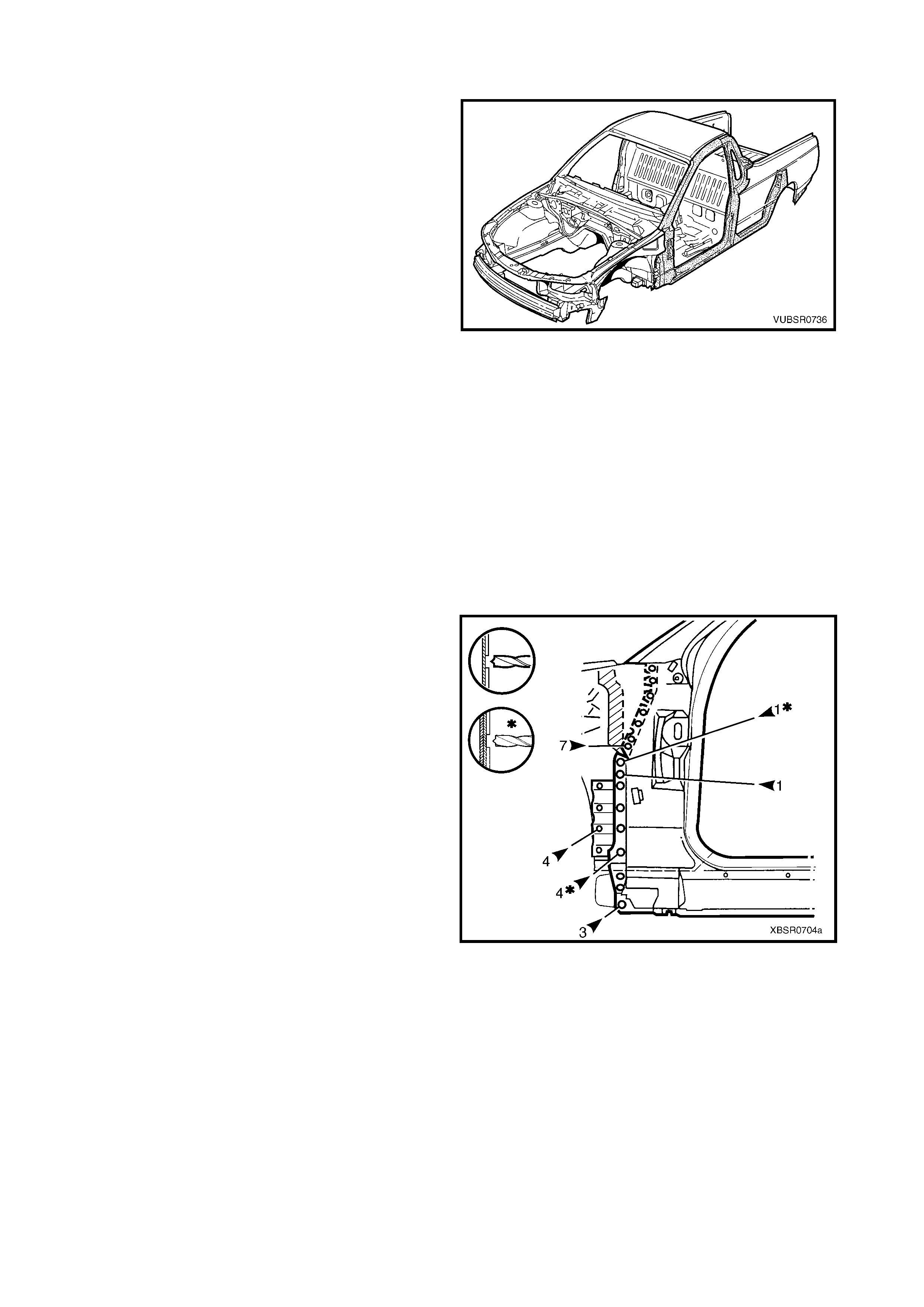
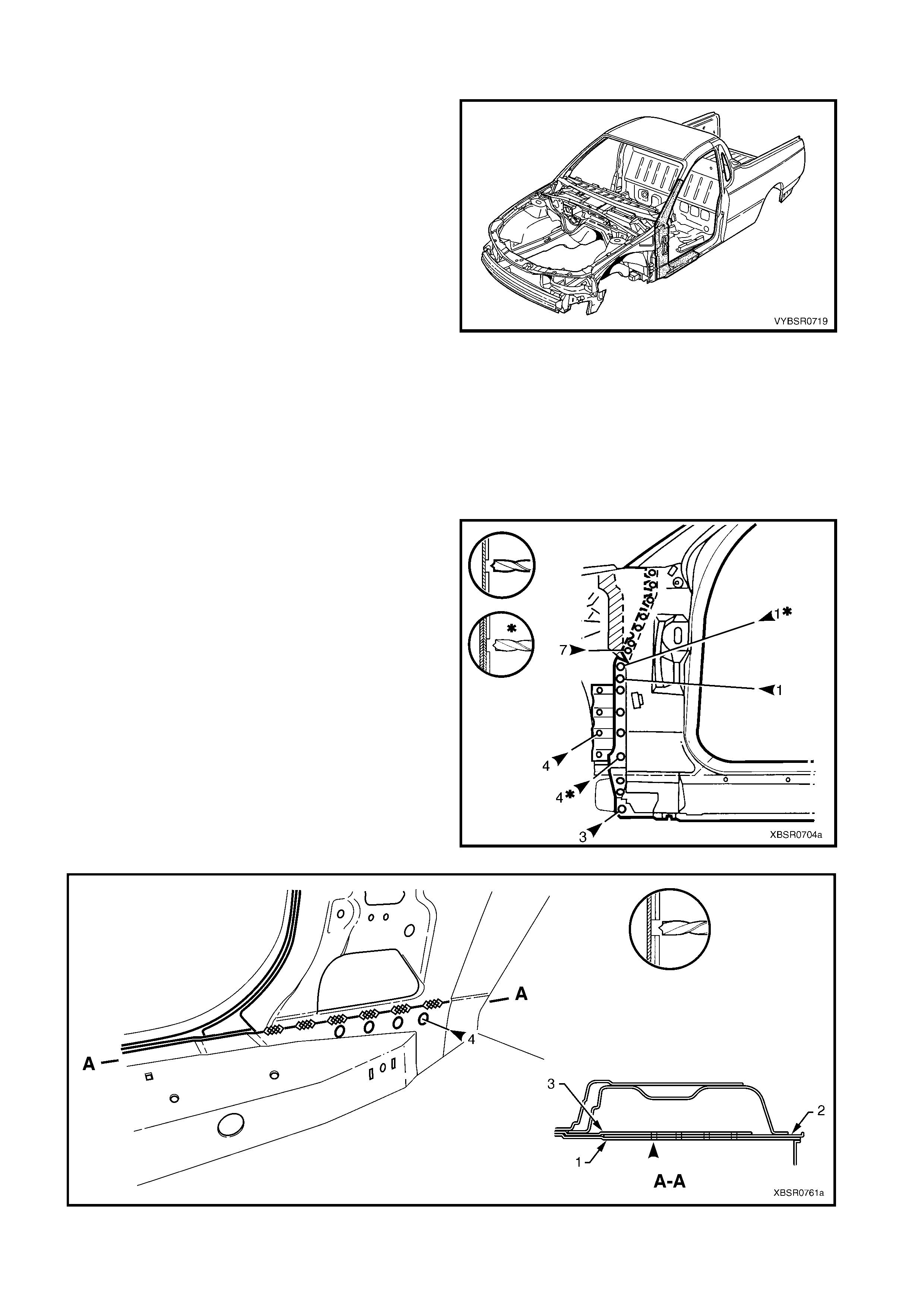
Figure 7C-37
6. Remove the front wheelhouse panel upper side
rail, refer to Section 4, 2.5 FRONT
WHEELHOUSE PANEL UPPER SIDE RAIL.
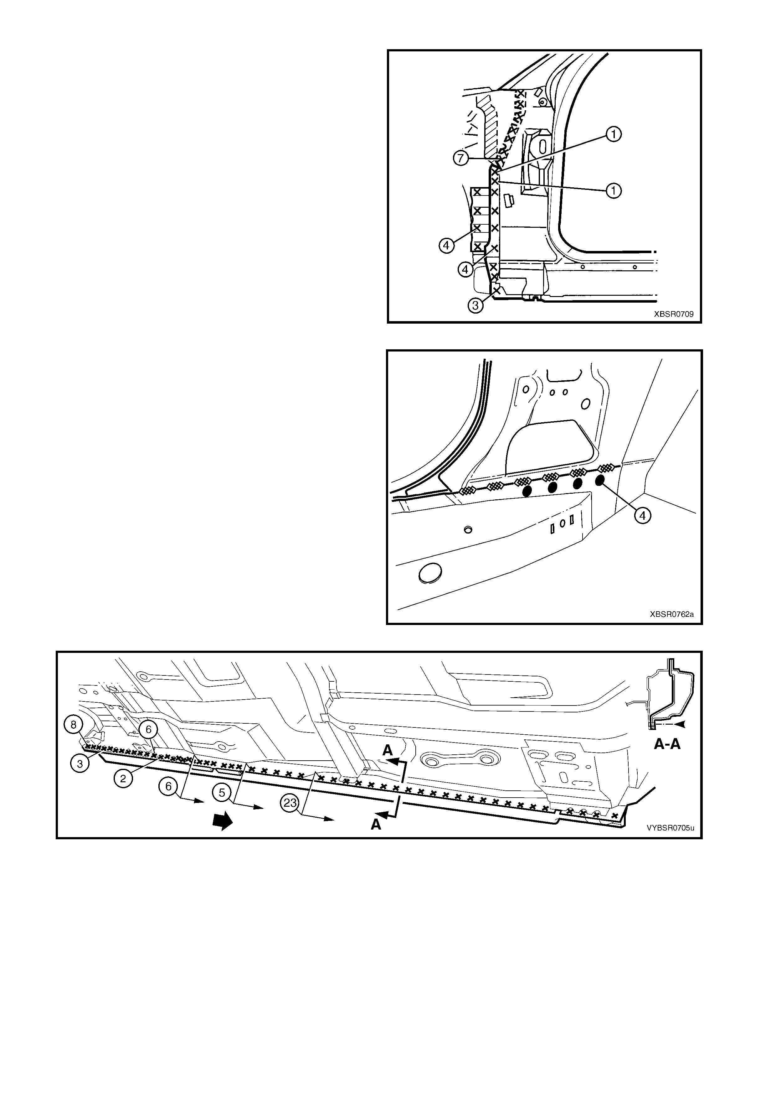
7. Spot cut the welds attaching the door opening
frame assembly to the inner rocker panel and to
the hinge pillar inner panel assembly.
NOTE: In order to spot cut the uppermost of these
welds it may be necessary to cut and peel back the
section of hinge reinforcement panel covering the
welds, to gain the required access.
8. If required, spot cut the welds attaching the inner
rocker panel (1) and hinge pillar inner panel
assembly (2) to the rock er panel reinforcement (3) .
Refer to Figure 7C-39.
NOTE 1: Not all vehicles have these welds.
NOTE 2: The MIG welds should not have to be
removed.
Figure 7C-38
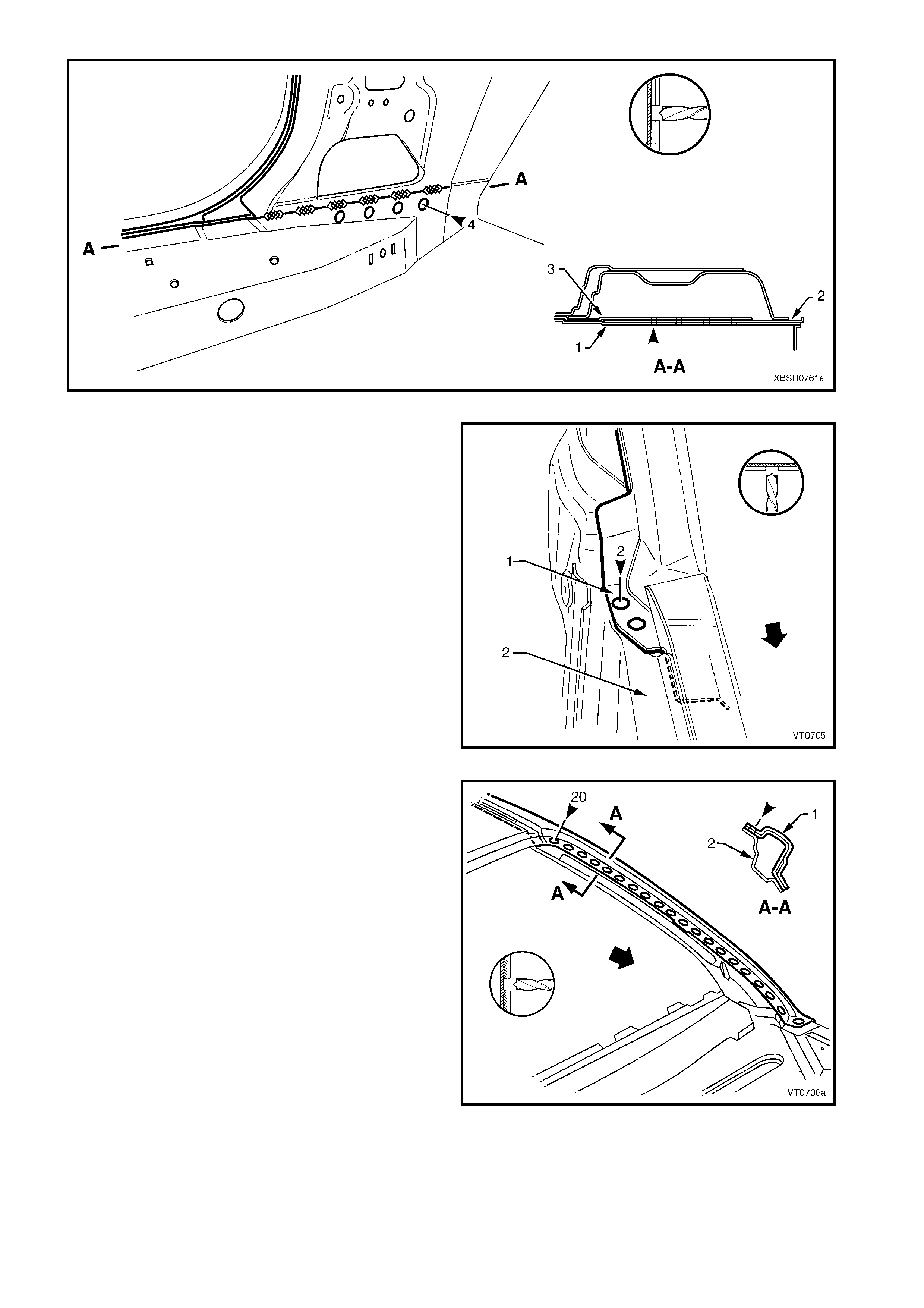
Figure 7C-39
9. Spot cut the two welds at the base of the hinge
pillar, attaching the door opening frame assembly
(1) to the hinge pillar inner panel assembly (2).
Figure 7C-40
10. Spot cut the welds on the windshield side flange,
attaching the door opening frame assembly (1) to
the hinge pillar inner panel assembly (2).
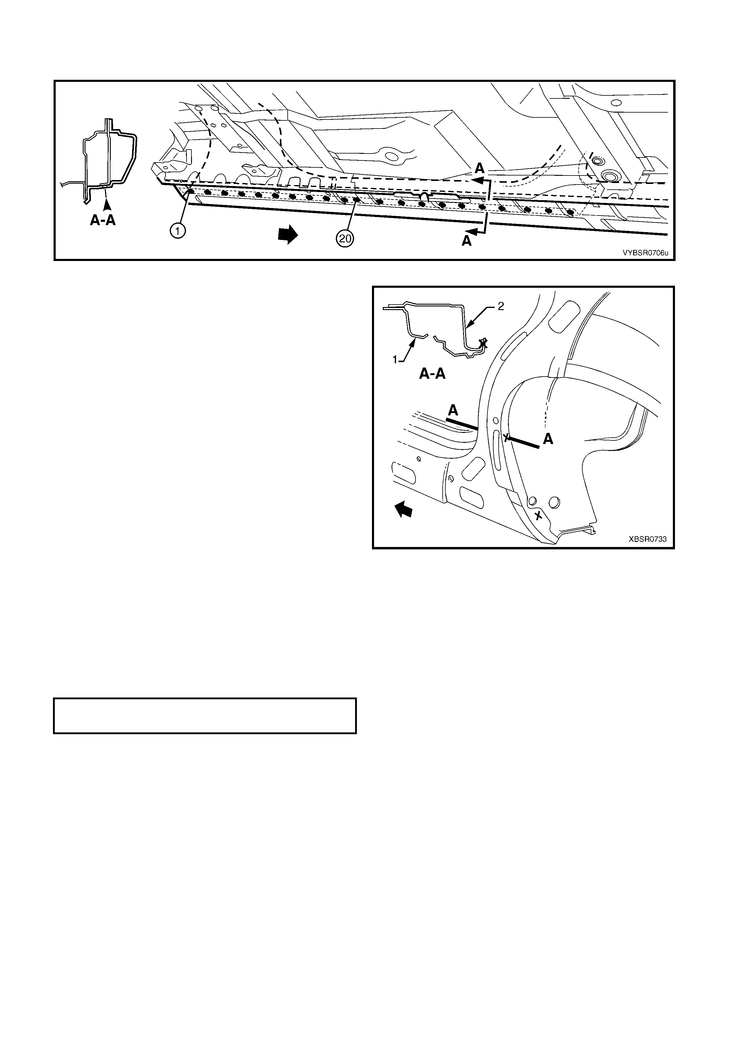
11. Spot cut along the vertical flange below the rocker
panel to separate the door opening frame
assembly from the inner rocker panel, refer to
Figure 7C-42.
Figure 7C-41
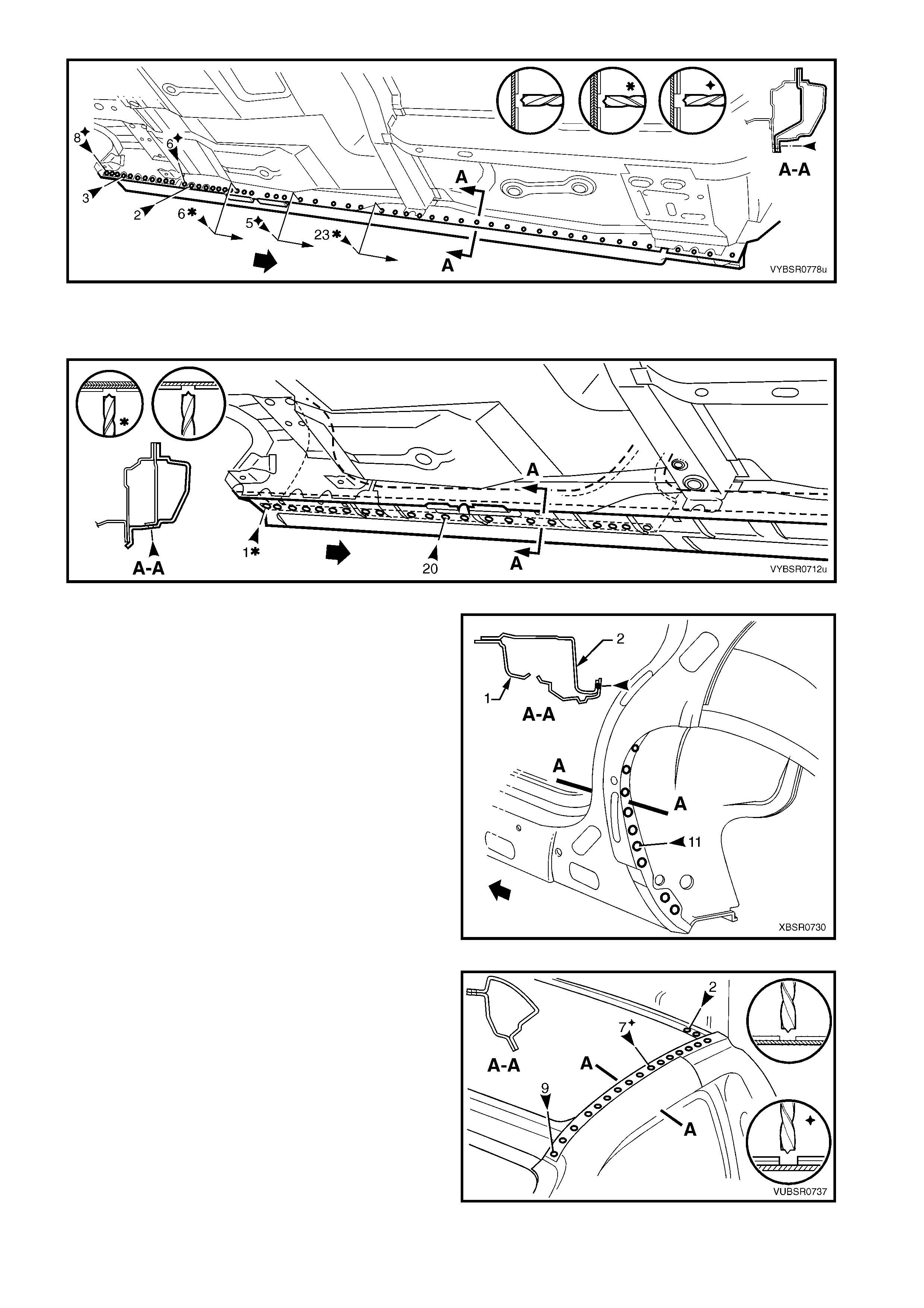
Figure 7C-42
12. Spot cut from below, up into the rocker panel, the welds attaching the door opening frame assembly to the
quarter panel inner assembly, refer to Figure 7C-43.
Figure 7C-43
13. Spot cut the welds around the rear wheel arch,
joining the door opening fram e assem bly (1) to the
quarter panel inner assembly (2).
NOTE: Som e of thes e welds may have been removed
with the rear quarter panel.
Figure 7C-44
14. Spot cut the welds along the roof flange.
NOTE: Many of these welds may have been removed
with the roof panel.
Figure 7C-45
15. Spot cut the welds attaching the door opening
frame assembly to the side inner upper front panel.
16. Grind off the MIG weld (1) attaching the door
opening frame assembly to the front seatback
panel.
17. Grind off the MIG weld (2) attaching the door
opening frame assembly to the side inner upper
front panel.
Figure 7C-46
18. Spot cut the welds attaching the door opening
frame assembly to the roof rear panel.
Figure 7C-47
19. Spot cut the welds on the flange surrounding the
front door opening, attaching the door opening
fram e ass embly to the hinge pillar inner as sembly,
inner rocker panel and quarter panel inner
assembly.
20. Spot cut the welds attaching the door opening
frame assembly to the side inner upper front panel,
side inner upper panel and quarter panel inner
assembly, refer to Figure 7C-49.
NOTE: W elds mark ed # may have been rem oved with
the rear quarter panel.
21. Remove the door opening frame assembly and
repair any damage to adjacent parts as required.
22. Check and rectify the alignment of the body as
required, refer to 3. BODY DIMENSIONS in
Section 3C.
Figure 7C-48
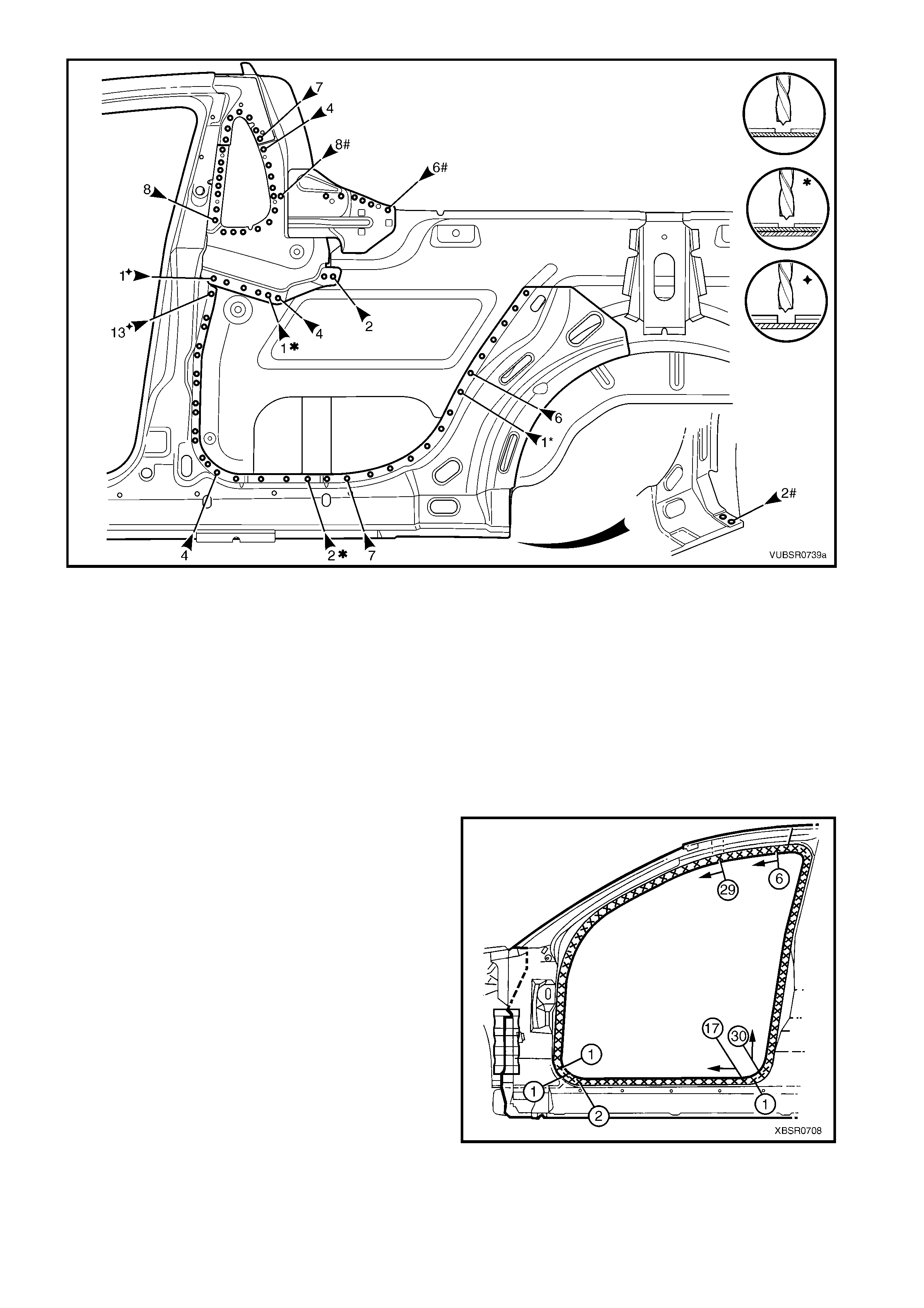
Figure 7C-49
REPLACE
NOTE 1: Spot welding is the preferred method for attaching of panels and should be used whenever possible.
Where the spot welding equipment will not access the required weld position, a plug weld should be performed.
NOTE 2: The same number and position of s pot welds ( or plug welds) s hould be used when replacing the panel,
as was used during manufacture, in order to maintain the original structural strength of the vehicle.
1. As required, mark the new panel with drilling locations in preparation for plug welding. Drill holes as required.
2. Prepare all mating surfaces and treat with Weld Through Primer (Item 1) as required, refer to
5. BODY SEALING, ADHESIVES & DEADENERS in Section 3C.
3. Apply Acrylic Spot Weld Sealer (Item 2), refer to 5. BODY SEALING, ADHESIVES & DEADENERS in
Section 3C.
4. Securely clamp the door opening frame assembly
in position on the vehicle body.
5. Begin attaching the door opening frame assembly
by spot welding around the front door opening
flange.
Figure 7C-50
6. Spot weld the door opening fr ame as semb ly to the
roof rear panel.
7. Spot or plug weld the door opening frame
assembly to the side inner upper front panel, side
inner upper panel and quarter panel inner
assembly, refer to Figure 7C-52.
Figure 7C-51
Figure 7C-52
8. Spot or plug weld the door opening frame
assembly along the roof flange.
NOTE: The remaining welds are made when the roof
panel is installed.
Figure 7C-53

9. Spot or plug weld the door opening frame
assembly to the side inner upper front panel.
10. MIG weld 50 mm (1) the door opening frame
assembly to the front seatback panel.
11. MIG weld 20mm (2) the side inner upper front
panel to the door opening frame assembly.
Figure 7C-54
12. Spot weld along the windshield flange, attaching
the door opening frame assembly to the hinge
pillar inner panel assembly.
Figure 7C-55
13. Spot weld in two places at the base of the hinge
pillar, attaching the door opening frame assembly
(1) to the hinge pillar inner panel assembly (2).
Figure 7C-56
14. Spot or plug weld the door opening frame
assembly to the inner rocker panel and to the
hinge pillar inner panel assembly.
NOTE: If the s heet metal was modified to allow acces s
to these welds, it should be repaired to its original
configuration.
Figure 7C-57
15. If removed, plug weld the inner rocker panel and
hinge pillar inner panel assembly to the rocker
panel reinforcement.
16. Spot weld the door opening fram e assem bly along
the vertical flange below the rocker panel, refer to
Figure 7C-59.
Figure 7C-58
Figure 7C-59
17. Plug weld up through the roc ker panel to attac h the door opening f ram e assembly to the quarter panel inner
assembly, refer to Figure 7C-60.
Figure 7C-60
18. Spot or plug weld in two places around the rear
wheel arch, attaching the door opening frame
assembly to the quarter panel inner assembly.
NOTE: These welds will be completed when the rear
quarter panel is replaced.
19. Replace front wheelhouse panel upper side rail,
refer to Section 4, 2.5 FRONT WHEELHOUSE
PANEL UPPER SIDE RAIL.
20. Replace the roof panel, refer to Section 9, ROOF.
21. Replace the rear quarter panel, refer to 2.1 REAR
QUARTER PANEL – REPLACE.
22. Install the door hinges, refer to 2.3 DOOR HINGE
(BODY SIDE) – REPLACE in Section 8.
23. Refinish and paint panels and other components
as required. Refer to Section 3, 1.3 PAINT
REFINISHING.
24. Apply Joint Sealer (Item 3) as required. Refer to
5. BODY SEALING, ADHESIVES & DEADENERS
in Section 3C.
25. Apply Cavity Wax (Item 8) as requir ed to the inside
of any box sections or areas inaccessible to paint,
refer to 6. CAVITY WAX in Section 3C.
Figure 7C-61
26. Apply Spray-on Deadener (Item 7) where applicable, refer to 5. BODY SEALING, ADHESIVES &
DEADENERS in Section 3C.
27. Install the dash panel retaining bolt through the hinge pillar and tighten to the specified torque.
28. Replace the windshield, quarter glass and rear window, refer to Section 1A6 STATIONARY GLASS the
MY 2003 VY & V2 Series II Service Information.
29. Insert Cavity Foam into the hinge & centre pillars as required, refer to Section 2, 10. CAVITY FOAM.
30. Install the rem aining com ponents as described in the appr opriate Section of the MY 2003 VY & V2 Series II
Service Information.
DASH PANEL RETAINING BOLT
TORQUE SPECIFICATION 35.0 – 45.0 Nm
2.7 DOOR OPENING FRAME ASSEMBLY – PARTIAL REPLACE, HINGE PILLAR
NOTE: Cavity Foam is used within the hinge & centre
pillar cavities. Care is required when repairing the
vehicle in these areas, refer to Section 2, 10.
CAVITY FOAM prior to beginning work for further
information.
REMOVE
1. Remove the adjacent bolt-on panels and
components as described in the appropriate
Section of the MY 2003 VY & V2 Series II Service
Information.
2. Secure an appropriate tool between the front door
opening flanges to maintain correct body
alignment.
3. Remove the windshield refer to Section 1A6,
STATIONARY WINDOWS in the MY 2003 VY &
V2 Series II Service Information.
4. Remove the dash panel retaining bolt from the
hinge pillar.
5. Remove the front wheelhouse panel upper side
rail, refer to Section 4, 2.5 FRONT
WHEELHOUSE PANEL UPPER SIDE RAIL.
Figure 7C-62
6. Spot cut the welds attaching the door opening
frame assembly to the inner rocker panel and to
the hinge pillar inner panel assembly.
NOTE: In order to spot cut the uppermost of these
welds it may be necessary to cut and peel back the
section of hinge reinforcement panel covering the
welds, to gain the required access.
7. If required, spot cut the welds attaching the inner
rocker panel (1) and hinge pillar inner panel
assembly (2) to the rock er panel reinforcement (3) ,
refer to Figure 7C-64.
NOTE 1: Not all vehicles have these welds.
NOTE 2: The MIG welds should not have to be
removed.
Figure 7C-63
Figure 7C-64
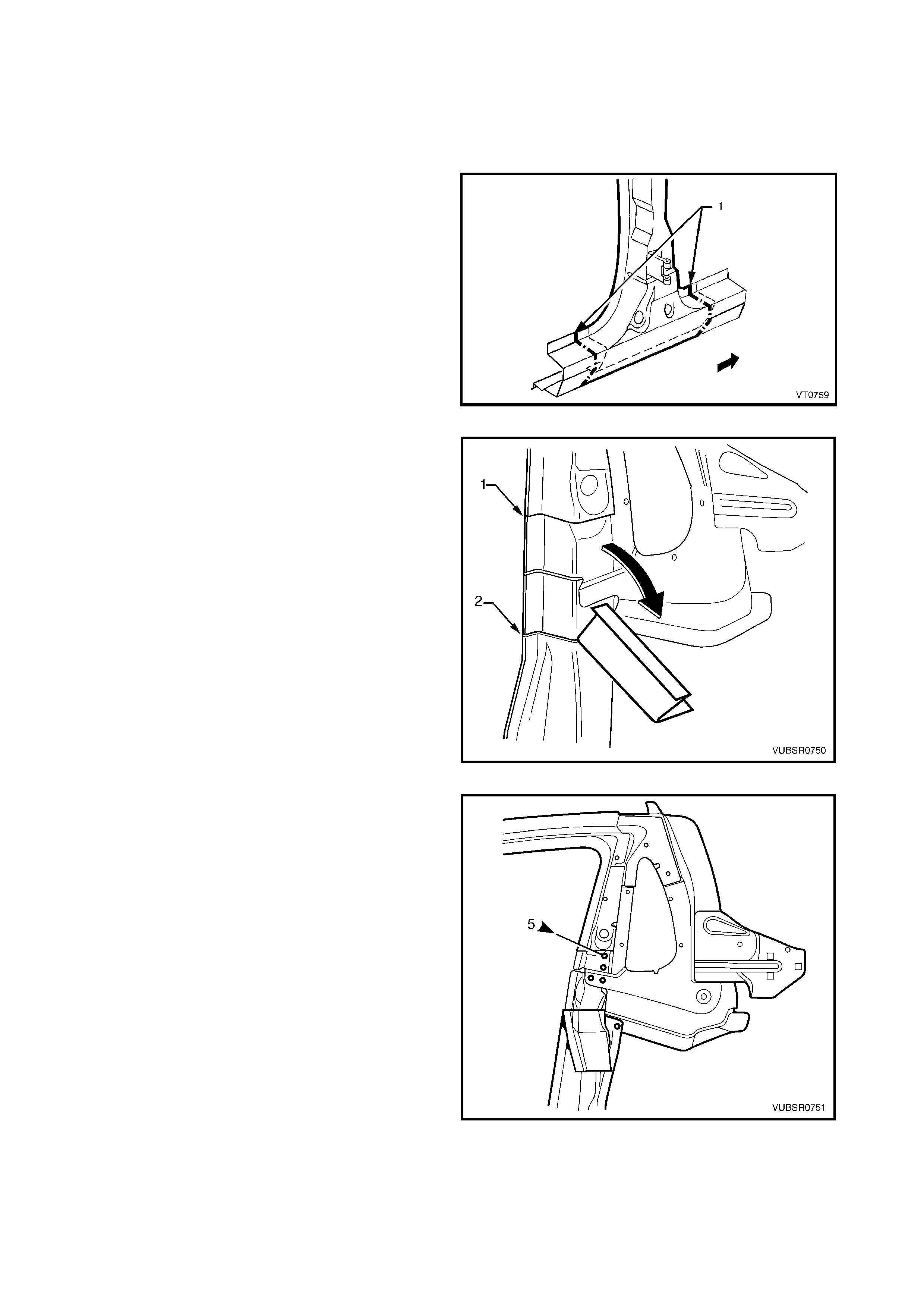
8. Spot cut the two welds at the base of the hinge
pillar, attaching the door opening frame assembly
(1) to the hinge pillar inner panel assembly (2).
Figure 7C-65
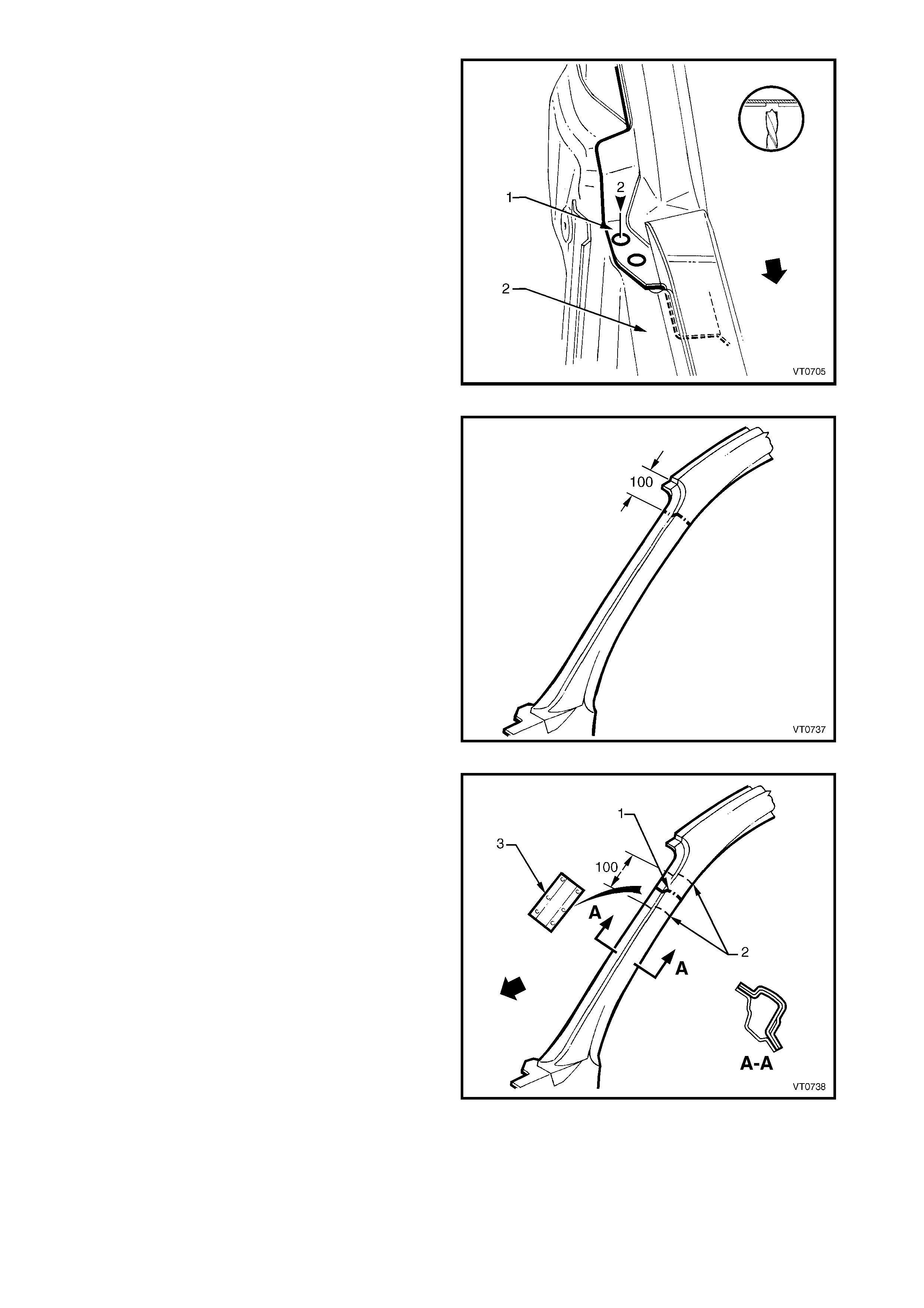
9. Select a cutting point on the hinge pillar. This cut
point should be within the region specified.
Figure 7C-66
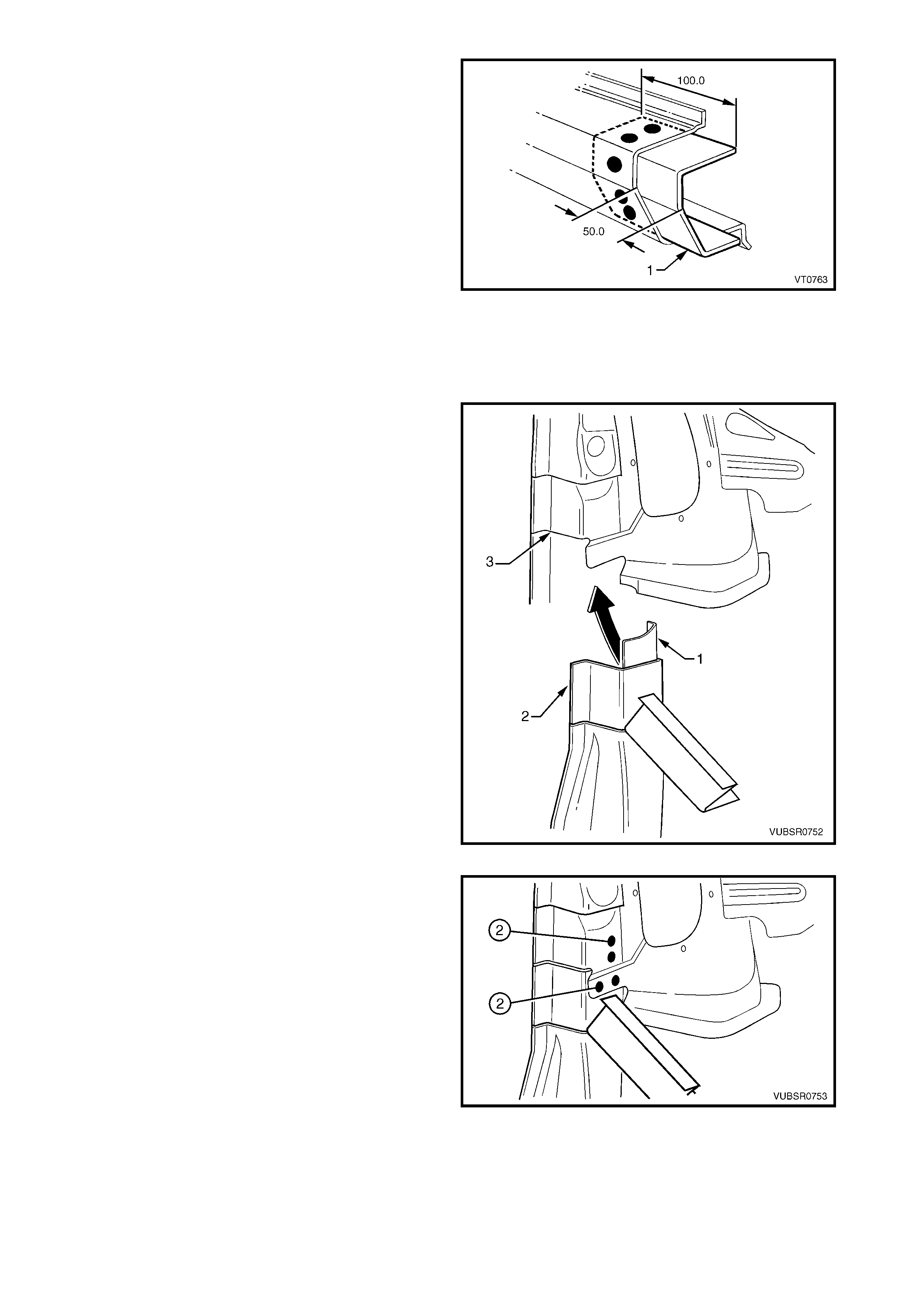
10. At the selected point (1), cut through the outer and
reinforcement panels, leaving the inner panel
intact.
11. Mark the inner panel at points 50 mm either side of
the cut line on the outer panel and cut the inner
panel at these two points (2). Spot cut the welds
and remove the 100 mm section of inner panel (3).
Figure 7C-67
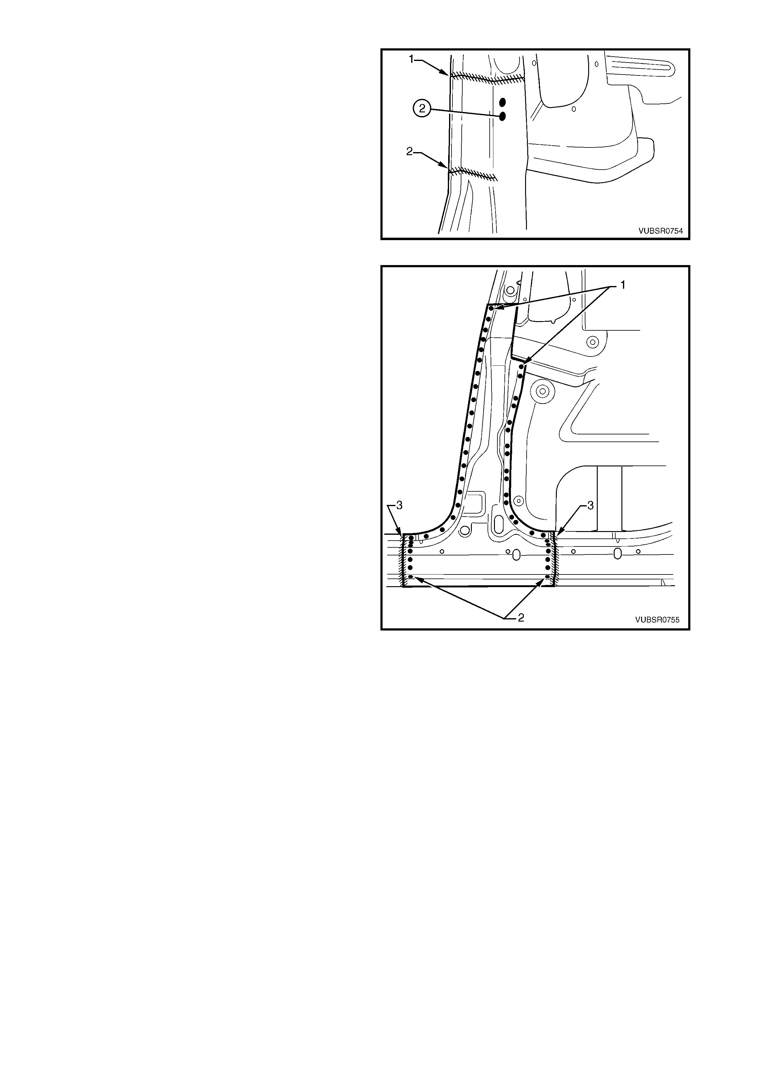
12. Spot cut the welds on the windshield side flange,
up to the point of the cut.
Figure 7C-68
13. Cut through the rocker panel section of the frame
door opening assembly. The cut point (1) should
be approximately 100 mm from the dimple (2) on
the flange. Cut through both the outer panel and
the reinforcement panel.
Figure 7C-69
14. Spot cut the welds on the flange along the front
door opening, from the cut near the top of the
hinge pillar (1) to the cut in the rocker panel (2).
15. Spot cut the welds along the flange (3) below the
rocker panel (to the point of the cut), separating
the door opening frame assembly from the inner
rocker panel.
16. Remove the partial hinge pillar from the vehicle,
then repair any damage to adjacent parts.
17. Check and rectify the alignment of the body as
required, refer to 3. BODY DIMENSIONS in
Section 3C.
Figure 7C-70
REPLACE
NOTE 1: Spot welding is the preferred method for
attaching of panels and should be used whenever
possible. Where the spot welding equipment will not
access the required weld position, a plug weld should
be performed.
NOTE 2: T he sam e num ber and position of spot welds
(or plug welds) should be used when replacing the
panel, as was used during manufacture, in order to
maintain the original structural strength of the vehicle.
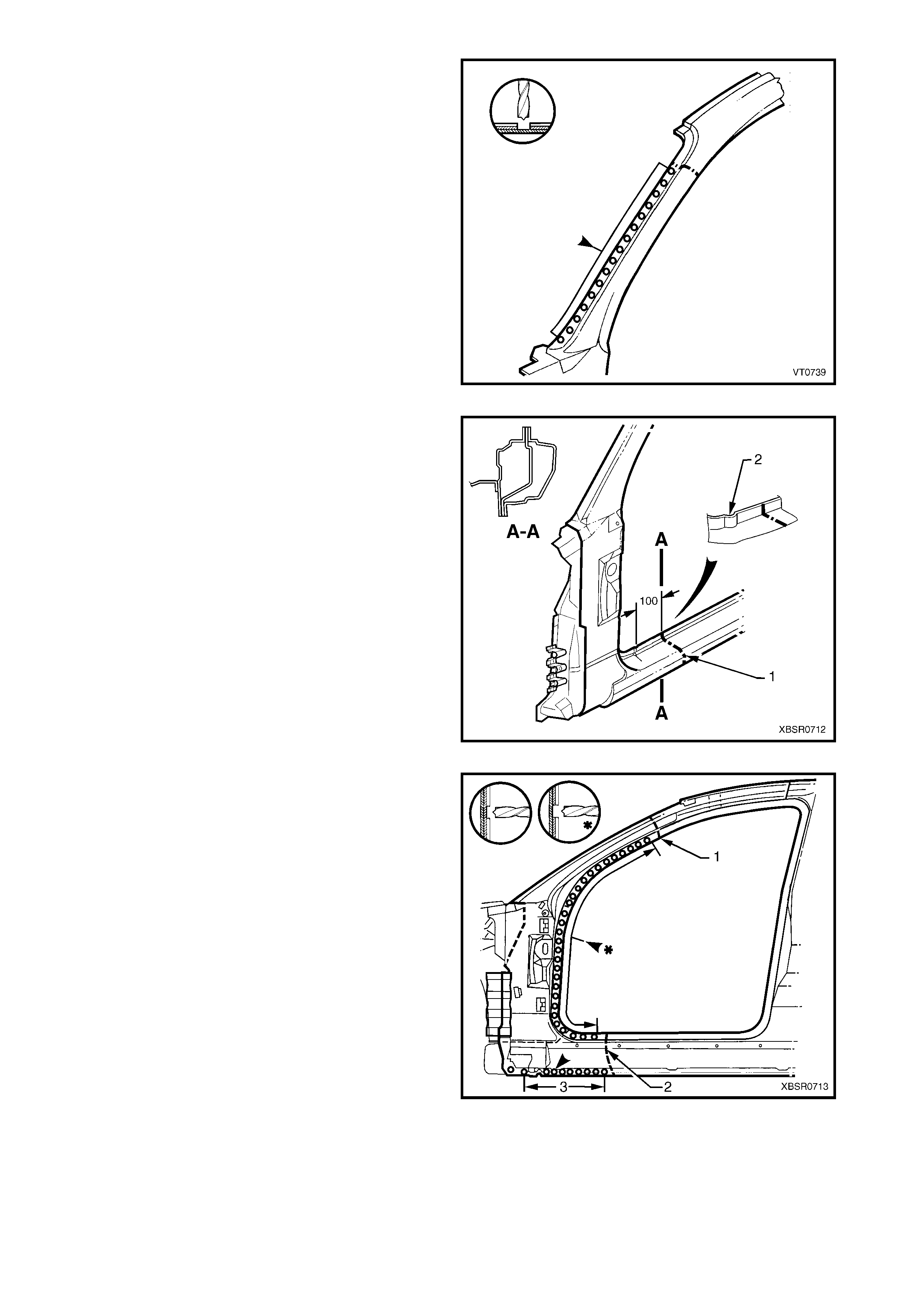
1. Cut a replacement panel section (1), accurately
measuring the position of cuts to match the section
removed.
Figure 7C-71
2. Remove a section of inner rocker panel (1), cut
50 mm each side of the cut in the roc ker panel (2).
This allows access for welding the rocker panel
reinforcement.
Figure 7C-72
3. Either manufacture a new section or cut an
existing length of surplus rocker panel section, to
form a reinforcement (1), approximately 100 mm in
length.
4. Prepare the mating surfaces and treat with Weld
Through Primer (Item 1) as required, refer to
5. BODY SEALING, ADHESIVES & DEADENERS
in Section 3C.
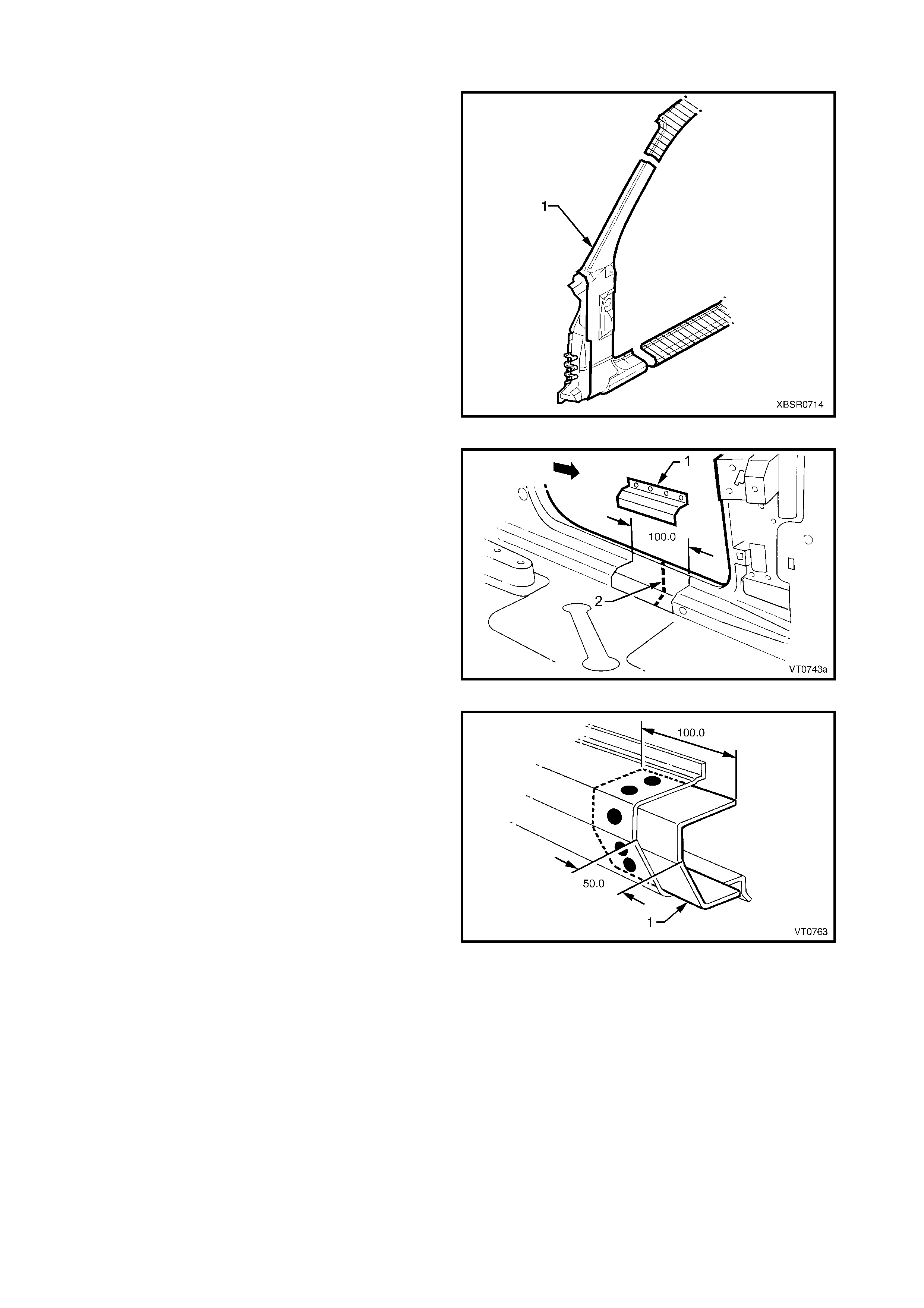
5. Clamp this reinforcement firmly behind the cut
section of rocker panel on the vehicle and spot or
plug weld in place. Position welds at a maximum
spacing of 35 mm apart.
Figure 7C-73
6. Using a similar technique, manufacture or cut a
section of reinforcement panel (1) (approximately
60 m m long) to fit on the inside of the replacem ent
hinge pillar outer panel (2) at the point of the cut.
NOTE: Remove the flanges from this reinforcement
panel.
7. Prepare the mating surfaces and treat with Weld
Through Primer (Item 1) as required, refer to
5. BODY SEALING, ADHESIVES & DEADENERS
in Section 3C.
8. Clamp the reinforcement panel firmly behind the
cut section of the hinge pillar outer and spot
weld (3) in place.
9. Mark the new hinge pillar panel with drilling
locations in preparation for plug welding where
required. Drill holes as marked.
10. Prepare the mating surfaces and treat with Weld
Through Primer (Item 1) as required, refer to
5. BODY SEALING, ADHESIVES & DEADENERS
in Section 3C.
11. Apply Acrylic Spot Weld Sealer (Item 2), refer to
5. BODY SEALING, ADHESIVES & DEADENERS
in Section 3C.
Figure 7C-74
12. Clamp the replacement panel in position on the
vehicle and check the door opening dimensions,
refer to 3. BODY DIMENSIONS in Section 3C.
Adjust position as required.
Figure 7C-75
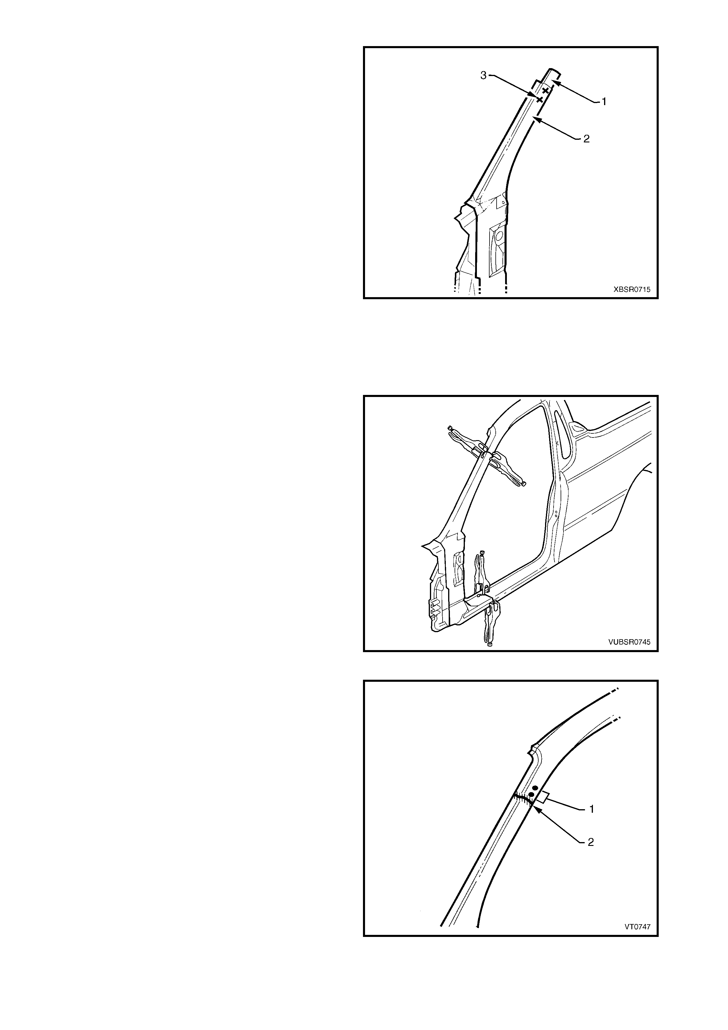
13. Plug weld (1) the top of the pillar to the
manufactured reinforcement, then MIG butt
weld (2) the two sections together.
Figure 7C-76
14. Plug weld (1) the new panel in the rocker panel
region, then MIG butt weld (2) the two sections
together.
Figure 7C-77
15. Gaining access through the removed section of
inner panel, MIG butt weld (1) the reinforcement
panel together.
16. Butt weld the removed access panel (2) in
position. Replace the spot welds with the same
number that was removed.
Figure 7C-78
17. Spot weld (1) the pillar along the door opening
flange.
18. Spot weld (2) the flange beneath the rocker panel,
attaching the new panel to the inner rocker panel.
Figure 7C-79
19. Spot weld (1) the pillar along the windshield
opening flange.
Figure 7C-80
20. Spot or plug weld the door opening frame
assembly to the inner rocker panel and to the
hinge pillar inner panel assembly.
NOTE: If the s heet metal was modified to allow acc es s
to these welds, it should be repaired to its original
configuration.
Figure 7C-81
21. If removed, plug weld the inner rocker panel and
hinge pillar inner panel assembly to the rocker
panel reinforcement.
Figure 7C-82
22. Gaining access through the section of removed
inner rocker panel, MIG butt weld (1) the new
section of rocker panel reinforcement to the
existing section.
23. Replace the removed section of inner rocker
panel (2) by MIG butt welding it in place and spot
welding it along the door opening flange. Replace
the spot welds with the same number of as were
removed.
24. Install the door hinges, refer to, 2.3 DOOR HINGE
(BODY SIDE) – REPLACE in Section 8.
25. Refinish and paint panels and other components
as required. Refer to Section 3, 1.3 PAINT
REFINISHING.
26. Apply Joint Sealer (Item 3) as required. Refer to
5. BODY SEALING, ADHESIVES & DEADENERS
in Section 3C.
Figure 7C-83
27. Apply Cavity W ax (Item 8) as required to the ins ide of any box s ections or areas inacces sible to paint, refer
to 6. CAVITY WAX in Section 3C.
28. Install the dash panel retaining bolt through the hinge pillar.
29. Replace the windshield, ref er to Sect ion 1A6 STATIONARY GLASS the MY 2003 VY & V2 Series II Service
Information.
30. Insert Cavity Foam into the hinge pillar as required, refer to Section 2, 10. CAVITY FOAM.
31. Install the rem aining com ponents as described in the appr opriate Section of the MY 2003 VY & V2 Series II
Service Information.
DASH PANEL RETAINING BOLT
TORQUE SPECIFICATION 35.0 – 45.0 Nm
2.8 DOOR OPENING FRAME ASSEMBLY – PARTIAL REPLACE, CENTRE PILLAR
NOTE: Cavity Foam is used within the hinge & centre
pillar cavities. Care is required when repairing the
vehicle in these areas, refer to Section 2,
10. CAVITY FOAM prior to beginning work for further
information.
REMOVE
1. Remove the adjacent bolt-on panels and
components as described in the appropriate
Section of the MY 2003 VY & V2 Series II Service
Information.
2. Secure the vehicle on a suitable fixture. As a
minimum, support the appropriate structural
sections of the vehicle on safety stands. Secure a
suitable tool between the front door opening
flanges to maintain alignment.
3. Rem ove the rear quarter panel, refer to 2.1 REAR
QUARTER PANEL – REPLACE.
Figure 7C-84
4. Cut the door opening frame assembly (1) as
shown.
NOTE: The upper cut is just below the recess and the
lower cut is approximately level with the centre pillar
upper reinforcement.
5. Spot cut the two welds attaching door opening
frame assembly to the centre pillar reinforcement.
6. Spot cut the welds attaching the door opening
frame assembly to the quarter panel inner
assembly.
7. Referring to Figure 7C-86, spot cut the welds
attaching the underbody jacking locator (1) and
remove.
8. Referring to Figure 7C-86, cut through the door
opening frame assembly (2) in two places shown
(3):
- At the join of the rocker panel reinforcement (4)
and centre pillar lower reinforcement (5) for the
front cut, and
- At the dimple in the flange for the rear cut.
NOTE: Mak e the f ront cut c aref ully as the rock er panel
reinforcement (4) must not be cut. The centre pillar
lower reinforcement (5) is removed with the centre
pillar section.
Figure 7C-85
9. Spot cut the welds on the flange attaching the centre pillar section to the inner rocker panel (6). Refer to
weld group A.
10. Spot cut the welds on the underside of the rocker panel attaching the centre pillar section to the quarter
panel inner assembly (7). Refer to weld group B.
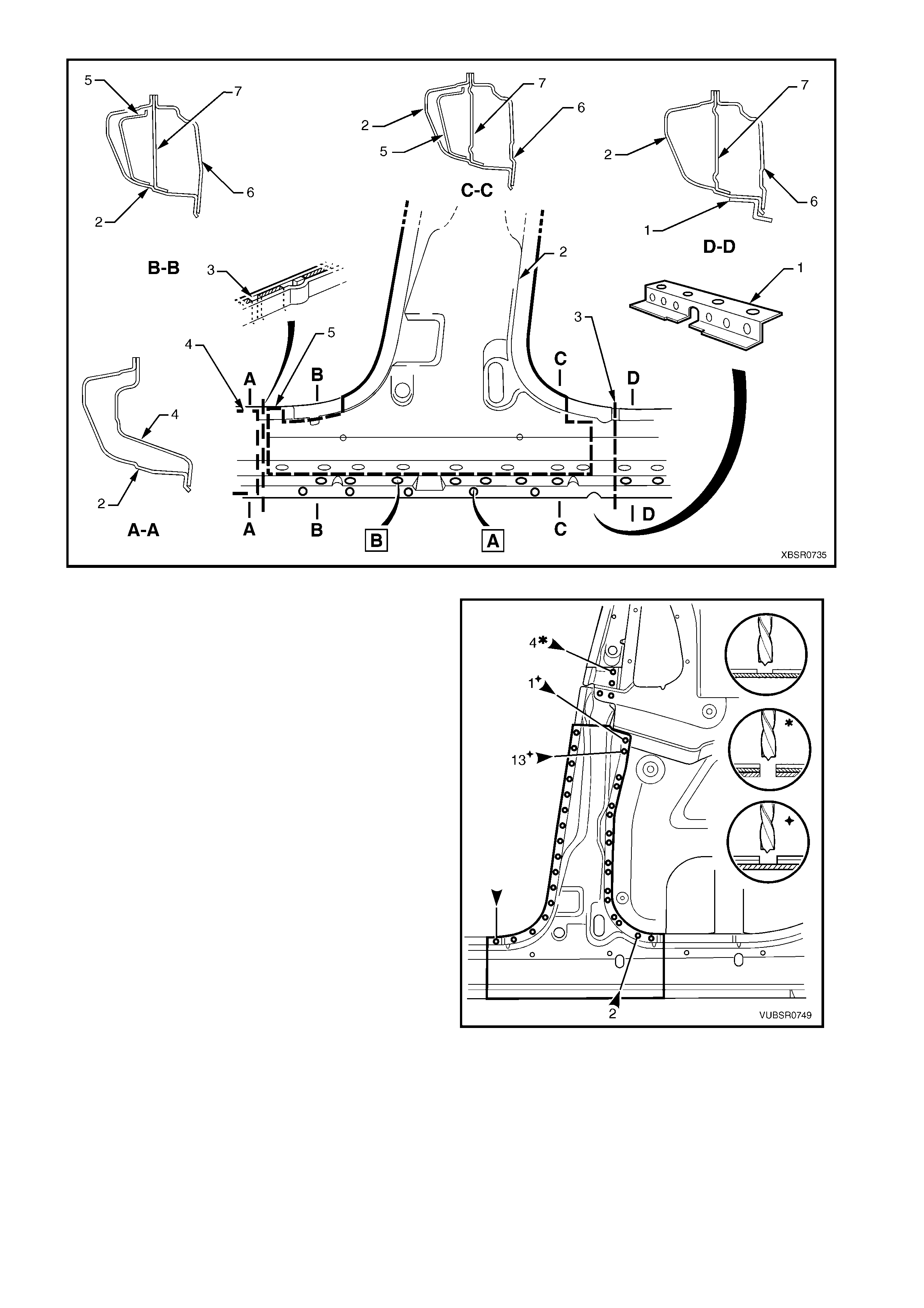
Figure 7C-86
11. Spot cut the welds attaching the front and rear
sides of the door opening frame assembly to the
quarter panel inner assembly.
NOTE: The number of welds will vary depending on
the cut locations.
12. Spot cut the four welds attaching the centre pillar
upper reinforcement to the centre pillar
reinforcement.
13. Remove the centre pillar section from the vehicle.
14. Repair any damage to adjacent parts as required.
Figure 7C-87
REPLACE
NOTE 1: Spot welding is the preferred method for attaching of panels and should be used whenever possible.
Where the spot welding equipment will not access the required weld position, a plug weld should be performed.
NOTE 2: The same number and position of s pot welds ( or plug welds) s hould be used when replacing the panel,
as was used during manufacture, in order to maintain the original structural strength of the vehicle.
1. Cut the r eplac ement door opening f r ame asse mbly
through rocker section as shown. Accurately
meas ur e the position of cuts to m atc h the rem oved
panel section.
Figure 7C-88
2. Cut the r eplac ement door opening f r ame assembly
below the recess to match the removed section
from the vehicle (1).
NOTE: Cut through the outer panel only.
3. Make a second cut approximately level with the
centre pillar upper reinforcement (2).
NOTE: Cut through the flange and front side ONLY.
4. Cut the required spot welds and carefully bend the
outer panel down to expose the spot welds
attaching the centre pillar upper reinforcement to
the centre pillar reinforcement.
Figure 7C-89
5. On the replacement panel, spot cut the five welds
attaching the centre pillar lower section to the
centre pillar upper reinforcement and remove the
section.
Figure 7C-90
6. Cut two sections from s urplus roc k er panel pieces ,
or manufacture new sections (1), each
approximately 100 mm in length.
7. Prepare the mating surfaces and treat with Weld
Through Primer (Item 1) as required, refer to
5. BODY SEALING, ADHESIVES & DEADENERS
in Section 3C.
8. Clamp these sections firmly behind both the cut
faces of rocker panel on the vehicle and spot or
plug weld in place. Perform the welds at a
maximum spacing of 35 mm.
9. Mark the new panel with drilling locations in
preparation for plug welding where required. Drill
holes as marked.
10. Prepare the mating surfaces and treat with Weld
Through Primer (Item 1) as required, refer to
5. BODY SEALING, ADHESIVES & DEADENERS
in Section 3C.
Figure 7C-91
11. Install the replacement panel in position, sliding the
centre pillar reinf orcement (1) and the centre pillar
lower reinforcement (2) behind the centre pillar
upper reinf orcement (3), until the front edge of the
lower reinf orcem ent butts against the f ront edge of
the upper reinforcement.
12. Manipulate the rocker panel section in position,
inserting the f ront firs t, then the r ear and c lamp the
assembly in place.
Figure 7C-92
13. Plug weld the centre pillar upper reinforcement to
the centre pillar lower reinforcement, two places
and the centre pillar reinforcement two places.
Figure 7C-93
14. Bend the outer panel bac k in pos ition and MIG butt
weld the sections together as shown (1 & 2).
15. Plug weld the outer panel, centre pillar upper
reinforcement and centre pillar reinforcement two
places.
Figure 7C-94
16. Plug weld (1) the front and rear sides of the door
opening fram e ass embly to the quarter panel inner
assembly.
NOTE: The number of welds will vary depending on
the cut locations.
17. Plug weld (2) the front and rear sides of the door
opening frame assembly to the rocker panel
reinforcements.
18. MIG butt weld (3) each join across the rocker
panel.
Figure 7C-95

19. Plug weld the flange attaching the centre pillar
section (1) to the inner rocker panel (2). Refer to
weld group A.
20. Plug weld on the underside of the rocker panel, the
centre pillar section to the quarter panel inner
assembly (3). Refer to weld group B.
21. Plug weld the underbody jacking locator (4) in
place.
22. Dress the welds by grinding or sanding, ensuring
sufficient material remains to guarantee the
strength of the weld. Finish the area using an
appropriate technique.
23. Refinish and paint panels and other components
as required. Refer to Section 3, 1.3 PAINT
REFINISHING.
24. Apply Joint Sealer (Item 3) as required. Refer to
5. BODY SEALING, ADHESIVES & DEADENERS
in Section 3C.
25. Apply Cavity Wax (Item 8) as requir ed to the inside
of any box sections or areas inaccessible to paint,
refer to 6. CAVITY WAX in Section 3C.
26. Insert Cavity Foam into the centre pillar as
required, refer to Section 2, 10. CAVITY FOAM.
27. Install the remaining components as described in
the appropriate Section of the MY 2003 VY & V2
Series II Service Information.
Figure 7C-96
2.9 DOOR OPENING FRAME ASSEMBLY – PARTIAL REPLACE, ROCKER PANEL
This procedure details the replacement of the rocker
panel section of the door opening frame assembly.
IMPORTANT: As there are several critical
reinforcements in the lower hinge area, the rocker
panel m us t not be c ut f or ward of the area s hown. If the
rocker panel is damaged forward of this area, replace
the rock er panel and par tial hinge pillar as one section.
Modify this procedure accordingly, also referring to
2.7 DOOR OPENING FRAME ASSEMBLY –
PARTIAL REPLACE, HINGE PILLAR.
REMOVE
1. Remove the adjacent bolt-on panels and
components as described in the appropriate
Section of the MY 2003 VY & V2 Series II Service
Information.
2. Secure the vehicle on a suitable fixture. As a
minimum, support the appropriate structural
sections of the vehicle on safety stands. Install
suitable bracing in the vehicle to ensure that the
correct body alignment is maintained when the
rocker panel section is removed.
3. Rem ove the rear quarter panel, refer to 2.1 REAR
QUARTER PANEL – REPLACE.
Figure 7C-97
4. Cut through the door opening frame assembly (1)
and the rocker panel reinforcement, no further
forward than the dimple in the flange (2).
Figure 7C-98
5. Using a s uitable cutting tool, c ut thr ough the centr e
pillar. Cut through both the door opening fram e (1)
and centre pillar lower reinforcement (2).
Figure 7C-99
6. If required, select a cutting point through the rocker
panel, anywhere rearward of the dimple (1) in the
flange. Cut through the door opening frame
assembly (2) only.
NOTE: If required, it may be preferable to remove the
complete rear section.
Figure 7C-100
7. Depending on the cut location, spot cut any welds
remaining around the wheelhouse as required
(most would be removed with the rear quarter
panel), attac hing the door opening frame ass embly
(1) to the quarter panel inner assembly (2).
8. Spot cut along the flange below the rocker panel
as required, to separate the rocker panel section
(including the underbody jacking locator) from the
inner rocker panel and quarter panel inner
assembly, refer to Figure 7C-102.
NOTE: Some of these welds may have been
previously removed with the rear quarter panel.
Figure 7C-101
Figure 7C-102
9. Spot cut the welds attaching the rock er panel section to the quarter panel inner as sembly as required, ref er
to Figure 7C-103.
NOTE: Depending on the cut line position, some of these welds would have been previously removed with the
rear quarter panel.
Figure 7C-103
10. As required, spot cut the welds along the edge of the door opening frame assembly, refer to Figure 7C-104.
11. Remove the panel from the vehicle, then repair any damage to adjacent parts.
12. Check and rectify the alignment of the body as required, refer to 3. BODY DIMENSIONS in Section 3C.
Figure 7C-104
REPLACE
NOTE 1: Spot welding is the preferred method for attaching of panels and should be used whenever possible.
Where the spot welding equipment will not access the required weld position, a plug weld should be performed.
NOTE 2: The same number and position of s pot welds ( or plug welds) s hould be used when replacing the panel,
as was used during manufacture, in order to maintain the original structural strength of the vehicle.
1. Cut a new replacement rocker panel section. Accurately measure the position of the cuts on the removed
section.
2. Remove a section of inner rocker panel (1), cut
50 mm each side of the existing cut in the rocker
panel (2). This allows access for welding the
rocker panel reinforcement.
Figure 7C-105
3. Manufacture or cut a reinforcement (1),
approximately 100 mm long, to fit on the INSIDE
ONLY of the existing rocker panel at the point of
the front cut.
4. Prepare the mating surfaces and treat with Weld
Through Primer (Item 1) as required, refer to
5. BODY SEALING, ADHESIVES & DEADENERS
in Section 3C.
5. Clamp the manufactured reinforcement firmly to
the inside of the rocker panel section of the door
opening frame assembly on the vehicle and plug
weld in position. Position welds at a maximum
spacing of 35 mm.
6. If the rear section has been cut, repeat the above
steps for the rear join.
Figure 7C-106
7. Manufacture or cut a reinforcement (1),
approximately 100 mm long, to fit inside of the
existing centre pillar section at the point of the cut.
8. Prepare the mating surfaces and treat with Weld
Through Primer (Item 1) as required, refer to
5. BODY SEALING, ADHESIVES & DEADENERS
in Section 3C.
9. Clamp the manufactured reinforcement panel
firmly to the inside of the outer panel of the door
opening frame assembly on the vehicle and plug
weld in position. Position welds at a maximum
spacing of 35 mm.
10. Mark the replacement rocker panel section with
drilling positions in preparation for plug welding as
required.
NOTE: The outer panel will be plug welded from the
outer side of the vehicle, while the rocker panel and
centre pillar reinforcements will be butt welded from
the inner side of the vehicle.
Figure 7C-107
11. Prepare all mating surfaces and treat with Weld Through Primer (Item 1) as required, refer to
5. BODY SEALING, ADHESIVES & DEADENERS in Section 3C.
12. Apply Acrylic Spot Weld Sealer (Item 2), refer to 5. BODY SEALING, ADHESIVES & DEADENERS in
Section 3C.
13. Install the replacement section onto the vehicle by sliding the front and centre pillar sections onto the
reinforcements, while lifting the rear into position.
14. Clamp the panel in position.
15. Weld the new centre pillar section in position by
plug welding (1).
16. MIG butt weld the reinforcement panel from inside
the centre pillar, through the seat belt retractor
opening in the inner panel immediately behind the
weld.
17. Finish the centre pillar attachment by MIG
welding (2) along the join of the outer panel.
Figure 7C-108
18. Plug weld (1) the replacement section at the front
join, then MIG butt weld (2) the two sections
together.
19. Repeat for the rear join if required.
Figure 7C-109
20. Gaining access through the section of removed
inner rocker panel, MIG butt weld (1) the new
section of rocker panel reinforcement to the
existing section.
21. Replace the removed section of inner rocker
panel (2) by MIG butt welding it in place and spot
welding it along the door opening flange. Replace
the spot welds with the same number of as were
cut.
22. Spot or plug weld the flanges of the door opening
frame assembly as required, refer to Figure 7C-
111.
NOTE: Us e the same number and pos ition of welds as
removed during removal.
Figure 7C-110
Figure 7C-111
23. Spot or plug weld the door opening frame along the flange below the rocker panel as required, refer to
Figure 7C-112.
NOTE: Place several welds only where the rear quarter panel will overlap the flange to hold the replacement
section in pos ition. Fully spot weld this f lange when the rear quarter panel is being attached, welding through all
panels.
Figure 7C-112
24. Plug weld up through the rocker panel to attach the replacement section to the quarter panel inner assembly.
Refer to Figure 7C-113.
NOTE: Place several welds only where the rear quarter panel will overlap the flange to hold the replacement
section in pos ition. Fully spot weld this f lange when the rear quarter panel is being attached, welding through all
panels.
Figure 7C-113
25. If required, spot weld the replacement section to
the quarter panel inner assembly around the rear
wheel arch at several places to retain new section
in position.
NOTE: Fully spot weld this flange when the rear
quarter panel is being attached, welding through all
three panels.
26. Clean up the welds made where the rear quarter
panel is located and prime all bare metal.
27. Replace the rear quarter panel, refer to 2.1 REAR
QUARTER PANEL – REPLACE.
28. Refinish and paint panels and other components
as required. Refer to Section 3, 1.3 PAINT
REFINISHING.
29. Apply Joint Sealer (Item 3) as required. Refer to
5. BODY SEALING, ADHESIVES & DEADENERS
in Section 3C.
30. Apply Cavity Wax (Item 8) as requir ed to the inside
of any box sections or areas inaccessible to paint,
refer to 6. CAVITY WAX in Section 3C.
31. Install the remaining components as described in
the appropriate Section of the MY 2003 VY & V2
Series II Service Information.
Figure 7C-114
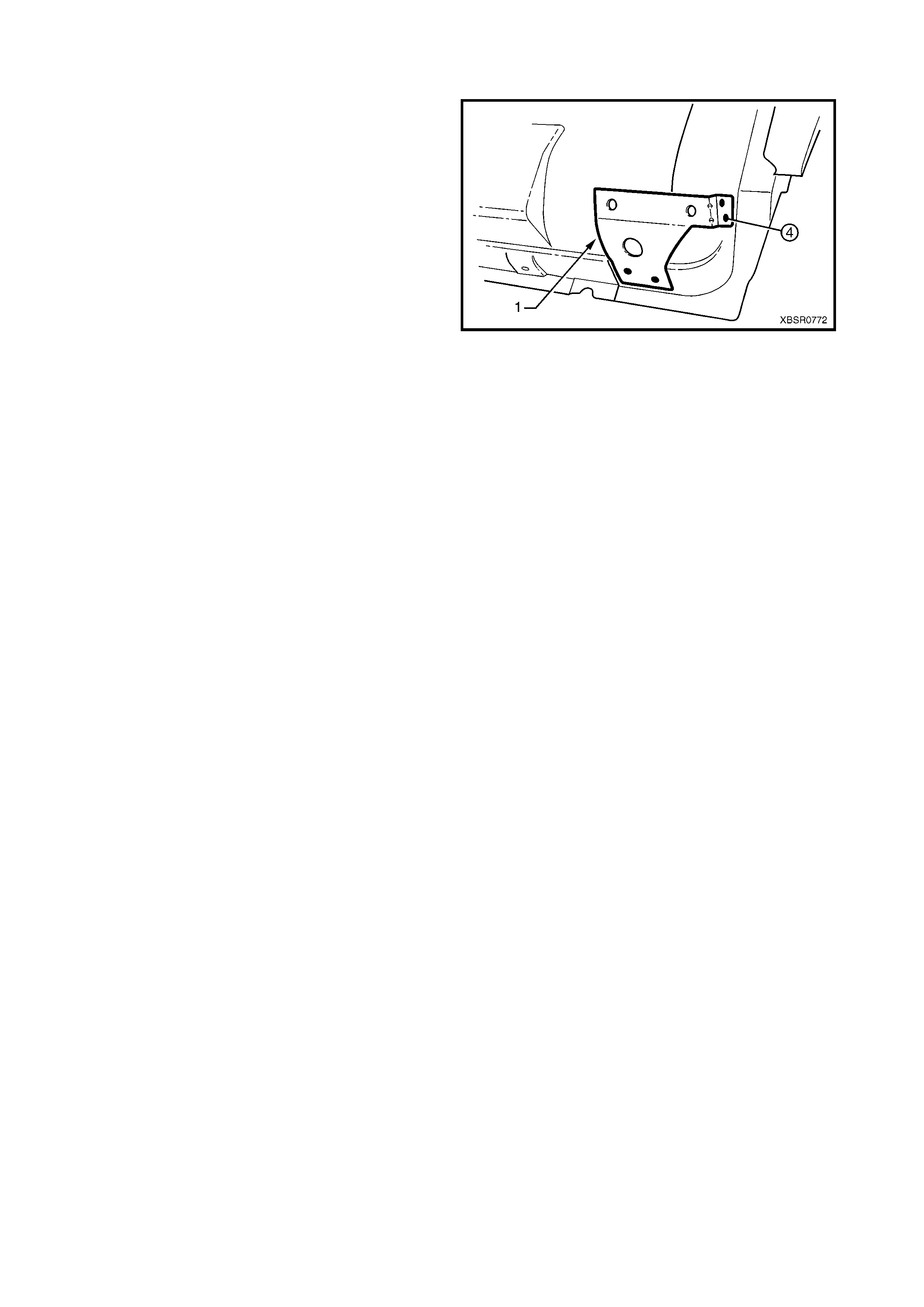
2.10 FENDER LOWER REAR BRACKET – REPLACE
The Fender lower rear bracket (1) is spot welded four
places, to the door opening frame assembly and is
used to attach the fender lower mounts.
Clamp the f ender support in position as shown prior to
plug welding and check the alignment of the fender to
the body and front door.
Refinish and paint panels and other components as
required. Refer to Section 3, 1.3 PAINT
REFINISHING.
Apply Cavity W ax (Item 8) as required to the inside of
any box sections or areas inaccessible to paint, refer to
6. CAVITY WAX in Section 3C.
Figure 7C-115
2.11 HINGE PILLAR INNER PANEL ASSEMBLY – REPLACE
REMOVE
1. Remove the adjacent bolt-on panels and
components as described in the appropriate
Section of the MY 2003 VY & V2 Series II Service
Information.
2. Remove the door opening frame assembly, refer
to 2.6 DOOR OPENING FRAME ASSEMBLY –
REPLACE, or remove the hinge pillar section of
the door opening frame assembly, refer to
2.7 DOOR OPENING FRAME ASSEMBLY –
PARTIAL REPLACE, HINGE PILLAR.
3. If required, rem ove the dash panel assem bly, ref er
to Section 5 COCKPIT MODULE in this
Supplement.
NOTE: If the dash panel assem bly is not damaged an
alternative is provided in this procedure.
4. Add bracing as required to maintain the alignment
of the vehicle structure.
Figure 7C-116
5. Grind the MIG welds (1) attaching the hinge pillar
inner panel assembly to the inner rocker panel.
Figure 7C-117
6. Spot cut the welds attaching the hinge pillar inner
panel assembly to the roof front header and
quarter panel inner extension.
NOTE: Structural adhesive is applied to join (1). If the
roof panel has not been r emoved, it will be very diff ic ult
to remove the panel. As an alternative:
- If only the lower section is damaged, detach the
hinge pillar inner upper panel (1) from the hinge
pillar inner lower panel (2) and replace the lower
panel, or
- Cut the hinge pillar inner panel assembly (3)
approximately 50 mm from the top of the
windscreen aperture. If a partial replacement of
the door opening frame assembly is being
performed, this point is 50 mm above the cut in
the outer panels (4). Refer to Figure 7C-119.
Figure 7C-118
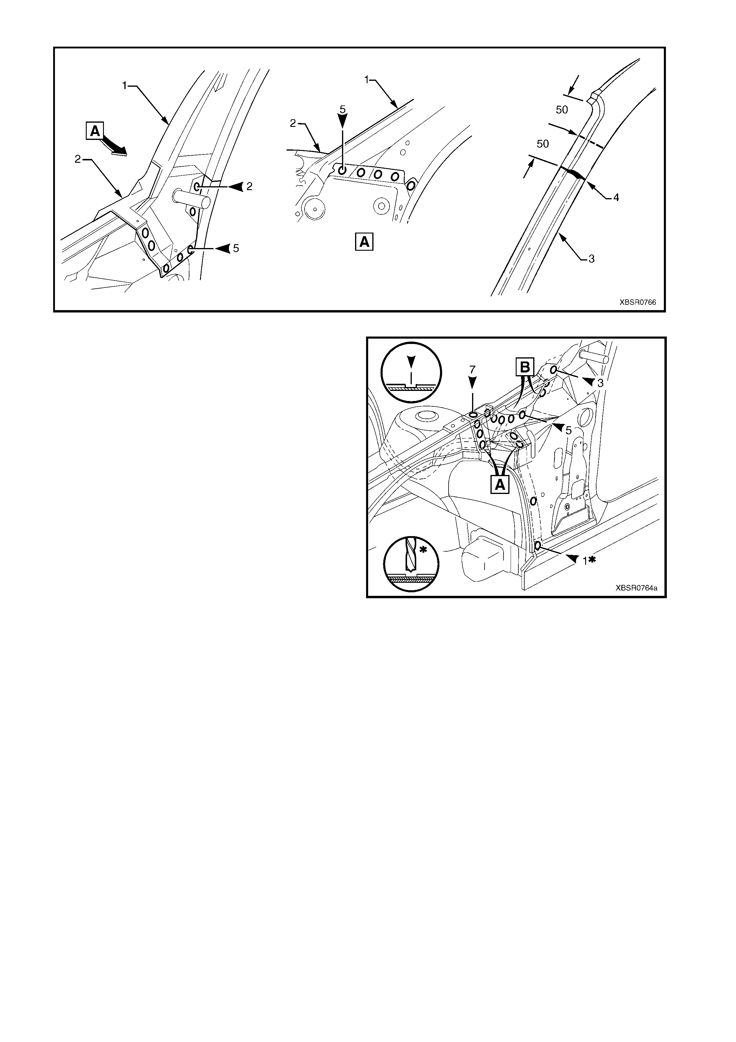
Figure 7C-119
7. Spot cut the welds attaching the hinge pillar inner
panel assem bly to the f ront wheelhouse panel and
front floor panel extension, refer to weld group A.
8. If the dash panel assem bly was not removed, spot
cut the eight welds attaching the adhesive
channels to the hinge pillar inner panel assembly,
refer weld group B.
9. If required, remove any remaining spot welds
where the wheelhouse panel upper side rail
attached the front wheelhouse panel and hinge
pillar inner panel assembly.
10. Cut the adhesive between the dash panel
assembly and hinge pillar inner panel assembly.
11. Remove the hinge pillar inner panel as s embly f r om
the vehicle and as required, clean off any
remaining adhesive and ensure the adhesive
channels are removed.
12. Repair any damage to adjacent parts as required. Figure 7C-120
REPLACE
NOTE 1: Spot welding is the preferred method for attaching of panels and should be used whenever possible.
Where the spot welding equipment will not access the required weld position, a plug weld should be performed.
NOTE 2: The same number and position of s pot welds ( or plug welds) s hould be used when replacing the panel,
as was used during manufacture, in order to maintain the original structural strength of the vehicle.
1. If an alternate removal method was used, referring to Figure 7C-119 either:
- Cut the replacement section to match the cut at the top of the hinge pillar, or
- Spot cut the welds attaching the hinge pillar inner upper panel to the hinge pillar inner lower panel.
2. Mark the new panel and drill holes in preparation for plug welding where required.
3. Prepare all mating surfaces and treat with Weld Through Primer (Item 1) as required, refer to
5. BODY SEALING, ADHESIVES & DEADENERS in Section 3C.
4. If the dash panel assembly was removed, it will be installed later, proceed to Step 7.
5. If the dash panel assembly was NOT removed, prepare the adhesive channels on the replacement section
and the dash panel assembly, refer to Section 5 COCKPIT MODULE.
6. Mix the dash panel silicone adhesive refer to Section 5 COCKPIT MODULE. Apply the adhesive to fill the
adhesive channels on the replacement section.
IMPORTANT: Only the correct material described in Section 5 COCKPIT MODULE is to be used.
7. If the f ull hinge pillar inner panel as s embly is being replaced, apply structural adhes ive (Item 6) to the mating
surfaces of the hinge pillar inner panel assembly and quarter panel inner extension, refer to
5. BODY SEALING, ADHESIVES & DEADENERS in Section 3C.
8. Install and clamp the new panel in position on the
vehicle.
NOTE: If the dash panel assembly was not removed,
place the hinge pillar inner panel assembly (1) slightly
lower and slide it upwards ensuring the dash panel
flange (2) seats into the adhesive channel.
9. Temporarily install the dash panel attaching bolts
through the hinge pillar inner panel assembly and
within the plenum chamber.
10. Finish the application of the dash panel adhesive,
refer to Section 5 COCKPIT MODULE.
Figure 7C-121
11. If the full hinge pillar inner panel assembly was
removed, spot or plug weld the hinge pillar inner
panel assembly to the roof front header and
quarter panel inner extension.
NOTE: Ensure the structural adhesive Item 6, is
applied to the join (1) refer to 5. BODY SEALING,
ADHESIVES & DEADENERS in Section 3C.
12. If only the lower section was removed, spot or plug
weld the hinge pillar inner upper panel (1) to the
hinge pillar inner lower panel (2), refer to Figure
7C-123.
13. If the pillar was cut near the top of the windscreen
aperture, either MIG butt weld the join (3) if the full
door opening frame assembly was removed, or
make two tack welds to secure it until the door
opening frame assembly hinge pillar section is
installed, refer to Figure 7C-123.
NOTE: This join forms the top access cut point
for joining of the reinforcement as described in
2.7 DOOR OPENING FRAME ASSEMBLY –
PARTIAL REPLACE, HINGE PILLAR.
Figure 7C-122
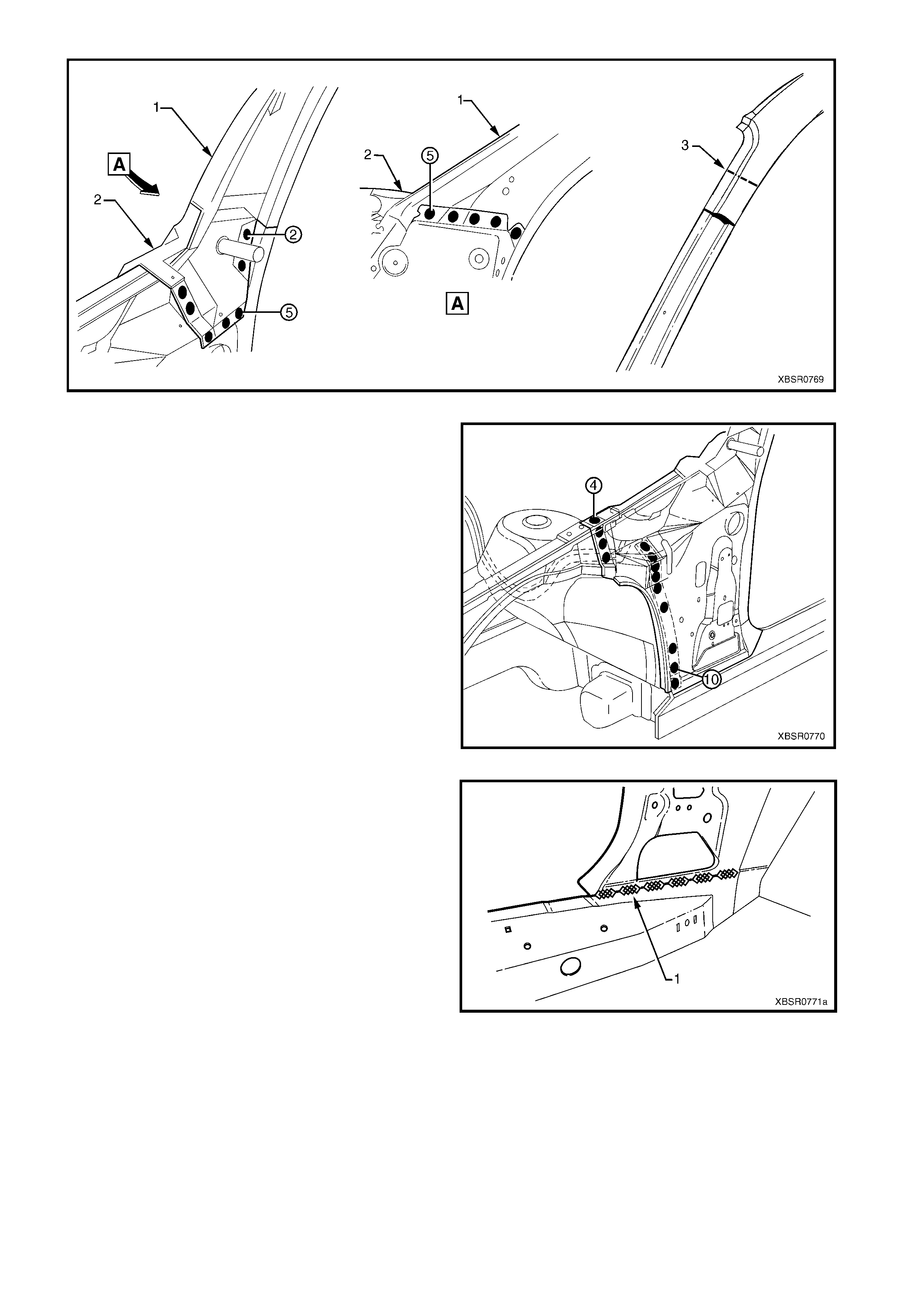
Figure 7C-123
14. Spot or plug weld the hinge pillar inner panel
assembly to the front wheelhouse panel and front
floor extension.
Figure 7C-124
15. MIG weld two places (1) across the inner rocker
panel and hinge pillar inner panel assembly.
16. Replace the door opening f rame assembly, refer to
2.6 DOOR OPENING FRAME ASSEMBLY –
REPLACE or the hinge pillar section of the
door opening frame assembly, refer to
2.7 DOOR OPENING FRAME ASSEMBLY –
PARTIAL REPLACE, HINGE PILLAR.
17. Refinish and paint panels and other components
as required. Refer to Section 3, 1.3 PAINT
REFINISHING.
18. Apply Joint Sealer (Item 3) as required. Refer to
5. BODY SEALING, ADHESIVES & DEADENERS
in Section 3C.
19. Apply Cavity Wax (Item 8) as requir ed to the inside
of any box sections or areas inaccessible to paint,
refer to 6. CAVITY WAX in Section 3C.
20. Install the remaining components as described in
the appropriate Section of the MY 2003 VY & V2
Series II Service Information.
Figure 7C-125
2.12 QUARTER INNER & REAR WHEE LHOUSE BRACE – REPLACE
REMOVE
1. Remove the adjacent bolt-on panels and
components as described in the appropriate
Section of the MY 2003 VY & V2 Series II Service
Information.
2. Remove the rear quarter panel, refer to
2.1 REAR QUARTER PANEL – REPLACE.
Figure 7C-126
3. Spot cut the welds attaching the quarter inner &
rear wheelhouse brace to the quarter panel inner
assembly and side inner upper panel, 18 places.
4. If not previously done, spot cut the welds attaching
the quarter inner & rear wheelhouse brace to the
side inner upper panel, 2 places.
5. Remove the brace and repair any adjacent
damage as required.
Figure 7C-127
REPLACE
NOTE 1: Spot welding is the preferred method for attaching of panels and should be used whenever possible.
Where the spot welding equipment will not access the required weld position, a plug weld should be performed.
NOTE 2: The same number and position of s pot welds ( or plug welds) s hould be used when replacing the panel,
as was used during manufacture, in order to maintain the original structural strength of the vehicle.
1. Mark the new panel and drill holes in preparation for plug welding where required.
2. Prepare all mating surfaces and treat with Weld Through Primer (Item 1) as required, refer to
5. BODY SEALING, ADHESIVES & DEADENERS in Section 3C.
3. Install and clamp the brace in position ensuring it
is located forward of the side inner upper panel
hole (1).
4. Spot or plug weld the brace to the side inner upper
panel and quarter , 18 places.
5. Clean up the welds and apply a coat of primer.
6. Install the rear quarter panel, refer to 2.1 REAR
QUARTER PANEL – REPLACE.
7. Refinish and paint panels and other components
as required. Refer to Section 3, 1.3 PAINT
REFINISHING.
8. Apply Joint Sealer (Item 3) as required. Refer to
5. BODY SEALING, ADHESIVES & DEADENERS
in Section 3C.
9. Apply Cavity Wax (Item 8) as requir ed to the inside
of any box sections or areas inaccessible to paint,
refer to 6. CAVITY WAX in Section 3C.
10. Apply Spray-on Deadener (Item 7) where
applicable, refer to 5. BODY SEALING,
ADHESIVES & DEADENERS in Section 3C.
11. Install the remaining components as described in
the appropriate Section of the MY 2003 VY & V2
Series II Service Information.
Figure 7C-128
2.13 QUARTER PANEL INNER ASSEMBLY – REPLACE
NOTE 1: This procedure also includes the rear
wheelhouse bracket and rear wheelhouse outer
extension (right-hand side only).
REMOVE
1. Remove the adjacent bolt-on panels and
components as described in the appropriate
Section of the MY 2003 VY & V2 Series II Service
Information.
2. Rem ove the rear quarter panel, refer to 2.1 REAR
QUARTER PANEL – REPLACE.
3. Remove the door opening frame assembly, refer
to 2.6 DOOR OPENING FRAME ASSEMBLY –
REPLACE.
Figure 7C-129
NOTE: If the damage is to the lower portion of the body, the partial door opening frame assembly, hinge pillar
and rocker panel sections can be removed.
4. Remove the welds attac hing the quarter inner & rear wheelhouse brace to the quarter panel inner ass em bly,
refer to 2.12 QUARTER INNER & REAR WHEELHOUSE BRACE – REPLACE.
5. Spot cut the welds attaching the rear wheelhouse bracket to the quarter panel inner assembly as required,
refer to Figure 7C-130.
Figure 7C-130

6. Grind the four MIG welds (1) from the inside of the
quarter panel inner assembly, joining the inner
rocker panel.
7. Structural adhesive (2) is applied along the flange
between the quarter panel inner assembly and
inner rocker panel. Either cut the flange or cut
around the adhesive and grind off the flange once
the panel is removed.
8. Spot cut the welds attaching the quarter panel
inner assembly to the side inner upper panel and
side inner upper front panel, refer to Figure 7C-
132.
NOTE 1: If the partial door opening frame assembly
hinge pillar section was removed, remove the welds
attaching the hinge pillar upper reinforcement to the
quarter panel inner assembly. Refer to 2.6 DOOR
OPENING FRAME ASSEMBLY – REPLACE and cut
the welds attaching the quarter panel inner assembly
to the side inner upper front panel from inside the
vehicle.
NOTE 2: For the right-hand side, either remove the
rear wheelhouse outer extension or spot cut the 10
welds attaching it to the quarter panel inner assembly.
Figure 7C-131
Figure 7C-132
9. As required, spot cut any remaining welds from where the door opening frame assembly and rear quarter
panel attached.
10. Remove the quarter panel inner assembly from the vehicle and repair any damage to adjacent parts as
required.
REPLACE
NOTE 1: Spot welding is the preferred method for attaching of panels and should be used whenever possible.
Where the spot welding equipment will not access the required weld position, a plug weld should be performed.
NOTE 2: The same number and position of s pot welds ( or plug welds) s hould be used when replacing the panel,
as was used during manufacture, in order to maintain the original structural strength of the vehicle.
1. Mark the new panel and drill holes in preparation for plug welding where required.
2. Prepare all mating surfaces and treat with Weld Through Primer (Item 1) as required, refer to
5. BODY SEALING, ADHESIVES & DEADENERS in Section 3C.
3. Apply structural adhesive (Item 6) to the mating surfaces of the quarter panel inner assembly and inner
rocker panel, refer to 5. BODY SEALING, ADHESIVES & DEADENERS in Section 3C.
4. Clamp the new panel in position on the vehicle.
5. Spot or plug weld the quarter panel inner assem bly, to the side inner upper panel and side inner upper front
panel, refer to Figure 7C-133.
NOTE: For the right-hand side, ins tall the wheelhouse outer extension ( 1) if rem oved, and weld to the side inner
upper panel.
Figure 7C-133
6. Spot or plug weld the rear wheelhouse bracket to quarter panel inner assembly, refer to Figure 7C-134.
Figure 7C-134
7. MIG weld four places 25 – 50mm each, the quarter
panel inner assembly to the inner rocker panel (1).
8. Spot or plug the quarter inner & rear wheelhouse
brace to the quarter panel inner ass embly, refer to
2.12 QUARTER INNER & REAR WHEELHOUSE
BRACE – REPLACE.
9. If the centre pillar upper reinforcement was not
removed, spot or plug weld it to the quarter panel
inner assembly, refer to 2.6 DOOR OPENING
FRAME ASSEMBLY – REPLACE.
10. Clean up welds and prime any bare metal.
11. Replace the door opening f rame assembly, refer to
2.6 DOOR OPENING FRAME ASSEMBLY –
REPLACE.
12. Replace rear quarter panel, refer to 2.1 REAR
QUARTER PANEL – REPLACE.
Figure 7C-135
13. Refinish and paint panels and other components as required. Refer to Section 3, 1.3 PAINT REFINISHING.
14. Apply Joint Sealer (Item 3) as required. Refer to 5. BODY SEALING, ADHESIVES & DEADENERS in
Section 3C.
15. Apply Cavity W ax (Item 8) as required to the ins ide of any box s ections or areas inacces sible to paint, refer
to 6. CAVITY WAX in Section 3C.
16. Apply Spray-on Deadener (Item 7) to the wheel side of the rear wheelhouse, refer to 5. BODY SEALING,
ADHESIVES & DEADENERS in Section 3C.
17. Install the rem aining com ponents as described in the appr opriate Section of the MY 2003 VY & V2 Series II
Service Information.
2.14 SIDE INNER UPPER PANEL – REPLACE
NOTE: This procedure also includes the cargo tie-
down brackets.
REMOVE
1. Remove the adjacent bolt-on panels and
components as described in the appropriate
Section of the MY 2003 VY & V2 Series II Service
Information.
2. Mount the vehicle on a suitable jig to maintain
correct body alignment when the side inner upper
panel is removed.
3. Rem ove the rear quarter panel, refer to 2.1 REAR
QUARTER PANEL – REPLACE.
4. Remove the quarter outer lower rear panel, refer to
2.4 QUARTER OUTER LOWER REAR PANEL –
REPLACE.
Figure 7C-136
5. Remove the quar ter inner lower rear extension, r efer to 2.3 QUARTER INNER LOWER REAR EXT ENSION
– REPLACE.
6. Remove the door opening frame assembly, refer to 2.6 DOOR OPENING FRAME ASSEMBLY –
REPLACE.
NOTE: If required, the partial door opening frame assembly centre pillar and rocker panel sections can be
removed. Spot cut the welds attaching the remaining door opening frame assembly to the side inner upper
panel, refer to 2.6 DOOR OPENING FRAME ASSEMBLY – REPLACE.
7. Remove the quarter inner & rear wheelhouse brace, refer to 2.12 QUARTER INNER & REAR
WHEELHOUSE BRACE – REPLACE.
8. Remove the welds attaching the side inner upper panel to the quarter lower rear panel, refer to
2.5 QUARTER LOWER REAR PANEL – REPLACE.
9. Remove the welds attaching the side inner upper panel to the rear end panel, refer to, 2.3 REAR END
PANEL – REPLACE in Section 10C.
10. Spot cut the welds and grind off the MIG welds attaching the side inner upper panel to the load floor panel,
refer to Figure 7C-137.
Figure 7C-137

11. Spot cut the welds (if not already removed) and
grind off the MIG welds (1) attaching the inner
upper side panel to the load compartment
extension panel.
12. Spot cut the welds attaching the side inner upper
panel to the quarter panel inner assembly, side
inner upper front panel, rear wheelhouse inner
panel, load floor panel outer extension and front
seatback panel outer, refer to Figure 7C-139.
13. Remove the side inner upper panel from the
vehicle and repair any damage to adjacent parts
as required.
Figure 7C-138
Figure 7C-139
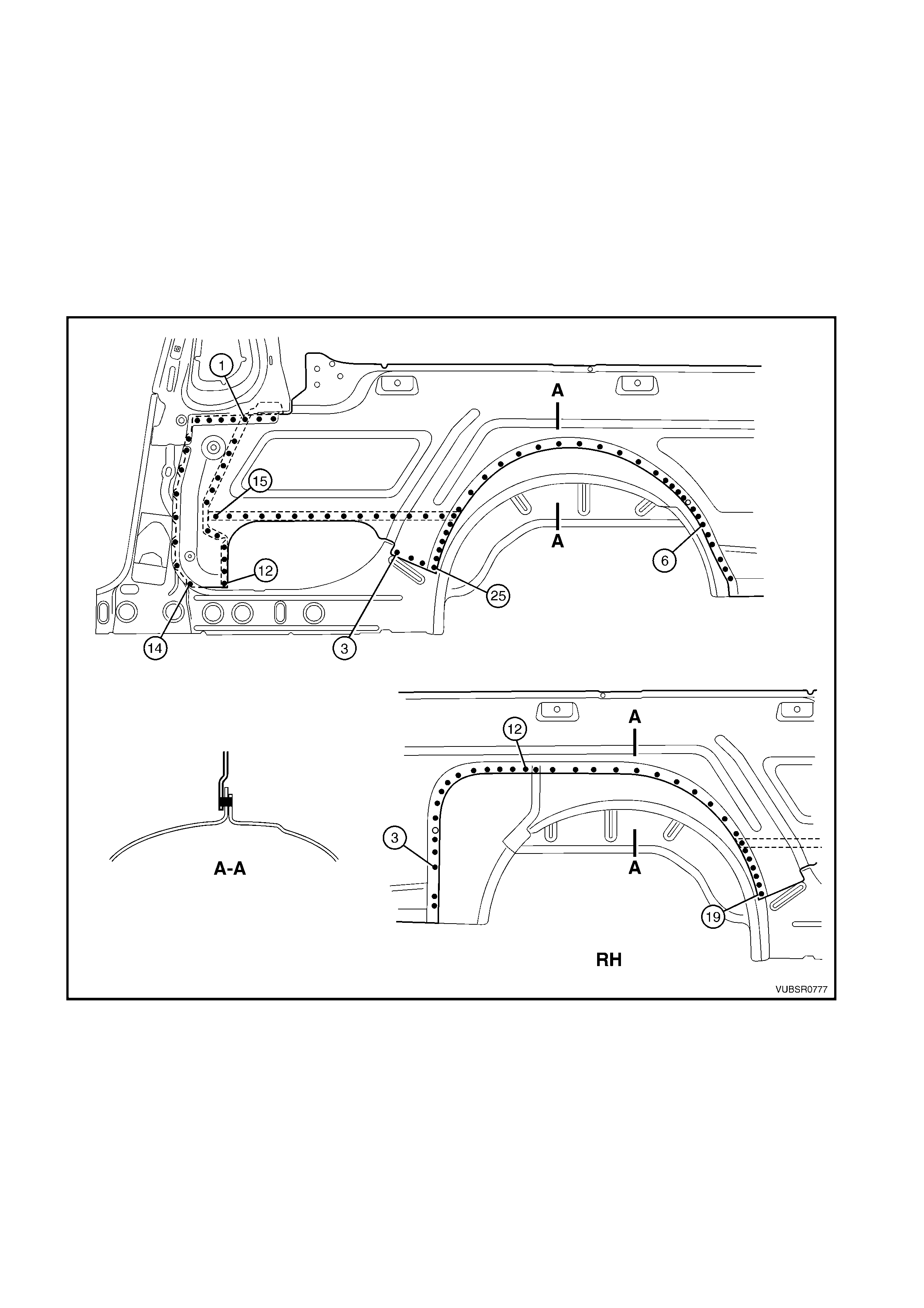
REPLACE
NOTE 1: Spot welding is the preferred method for attaching of panels and should be used whenever possible.
Where the spot welding equipment will not access the required weld position, a plug weld should be performed.
NOTE 2: The same number and position of s pot welds ( or plug welds) s hould be used when replacing the panel,
as was used during manufacture, in order to maintain the original structural strength of the vehicle.
1. Mark the new panel and drill holes in preparation for plug welding where required.
2. Prepare all mating surfaces and treat with Weld Through Primer (Item 1) as required, refer to
5. BODY SEALING, ADHESIVES & DEADENERS in Section 3C.
3. Clamp the new panel in position on the vehicle.
4. Spot or plug weld the side inner upper panel to the quarter panel inner assembly, side inner upper front
panel, rear wheelhouse inner panel, load f loor panel outer ex tension and fr ont seatback panel outer , refer to
Figure 7C-140.
Figure 7C-140
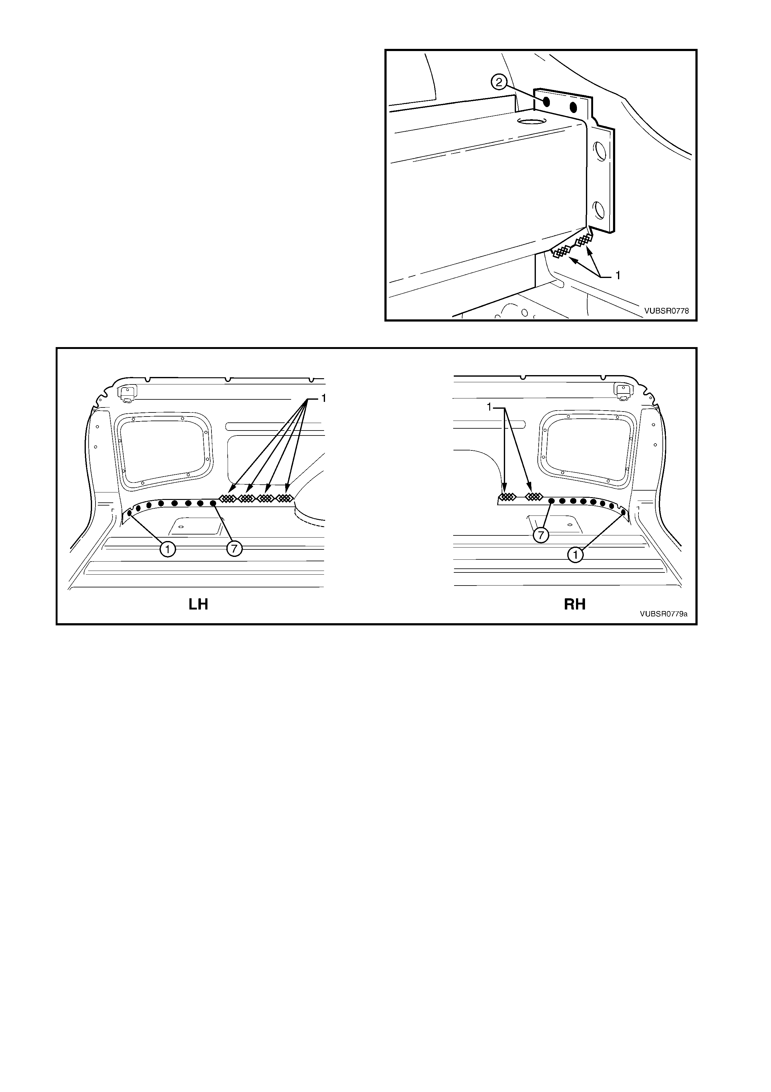
5. MIG weld (1) two places 15 – 20mm each, the side
inner upper panel to the load compartment
extension panel.
NOTE: Make the two spot welds (2) once the door
opening frame assembly and rear quarter panel have
been installed.
6. MIG weld the right-hand side inner upper panel (1)
four places 25 – 50mm each, or the left-hand side
inner upper panel (2) two places 25 – 50m m each,
to the load floor panel, refer to Figure 7C-142.
7. Install the quarter outer lower rear panel and spot
or plug to the side inner upper panel and load floor
panel, refer to Figure 7C-142.
NOTE: Also refer to 2.4 QUARTER OUTER LOWER
REAR PANEL – REPLACE.
8. Spot or plug weld the side inner upper panel to the
quarter lower rear panel, refer to 2.5 QUARTER
LOWER REAR PANEL – REPLACE.
Figure 7C-141
Figure 7C-142
9. Spot or plug weld the side inner upper panel to the rear end panel, refer to 2.3 REAR END PANEL in
Section 10.
10. Install the quarter inner lower rear ex tension, refer to 2.3 QUARTER INNER LOW ER REAR EXTENSION –
REPLACE.
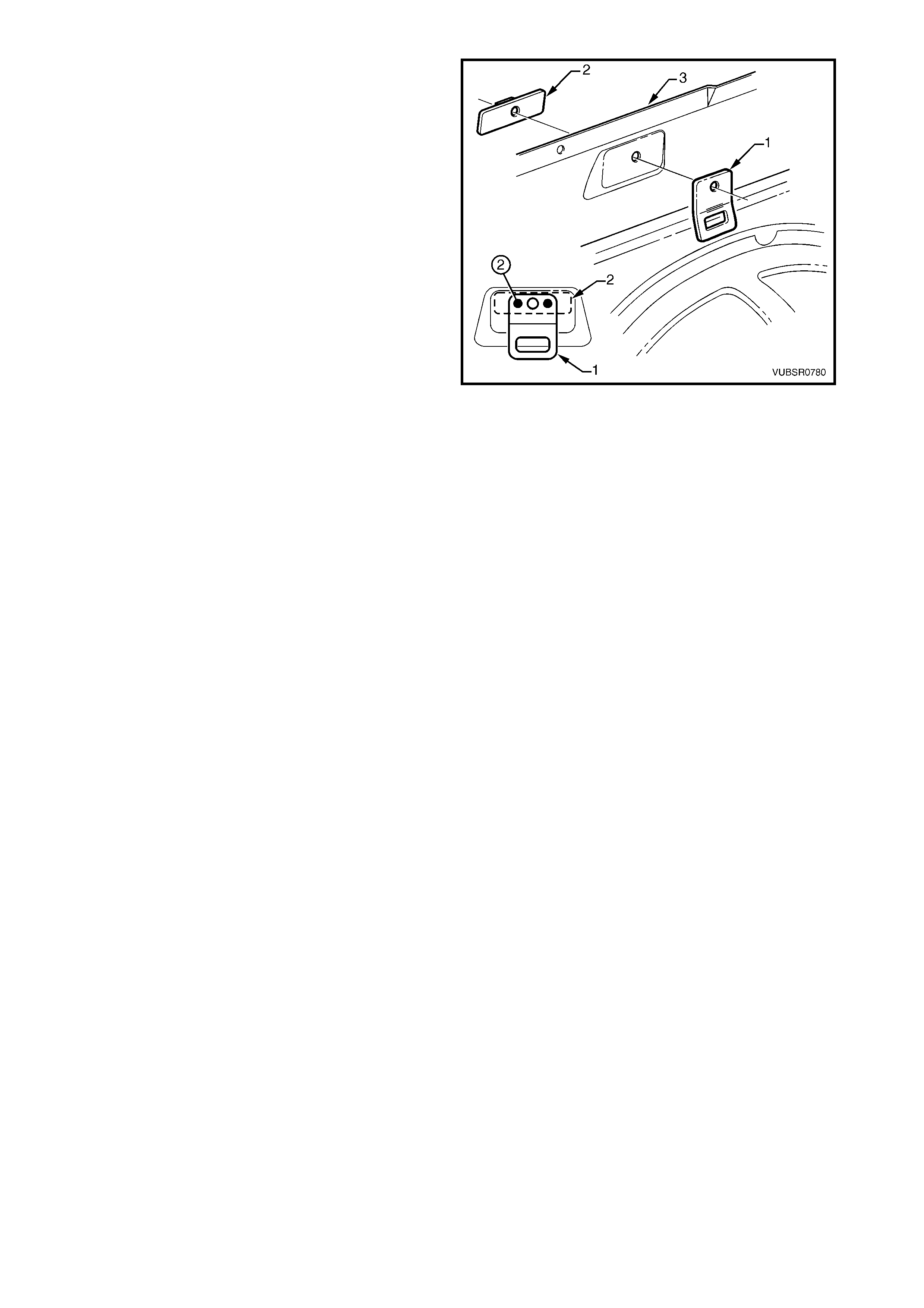
11. Clamp the cargo tie-down bracket (1) and the
cargo tie-down bracket anc hor plate (2) to the side
inner upper panel (3).
12. Spot or plug the three parts, two places.
13. Repeat for each of the two other brackets.
14. Clean up and prime the areas that will be covered
by the quarter inner & rear wheelhouse brace.
15. Install the quarter inner & rear wheelhouse brace,
refer to 2.12 QUARTER INNER & REAR
WHEELHOUSE BRACE – REPLACE.
16. Clean up and prime areas that will be covered by
the following panels.
17. Install the door opening frame assembly, refer to
2.6 DOOR OPENING FRAME ASSEMBLY –
REPLACE, or the centre pillar and rocker sections.
18. Install the rear quarter panel, refer to 2.1 REAR
QUARTER PANEL – REPLACE.
19. Refinish and paint panels and other components
as required. Refer to Section 3, 1.3 PAINT
REFINISHING.
Figure 7C-143
20. Apply Joint Sealer (Item 3) as required. Refer to 5. BODY SEALING, ADHESIVES & DEADENERS in
Section 3C.
21. Apply Cavity W ax (Item 8) as required to the ins ide of any box s ections or areas inacces sible to paint, refer
to 6. CAVITY WAX in Section 3C.
22. Apply Spray-on Deadener (Item 7) to the wheel side of the rear wheelhouse as required, refer to
5. BODY SEALING, ADHESIVES & DEADENERS in Section 3C.
23. Install the rem aining com ponents as described in the appr opriate Section of the MY 2003 VY & V2 Series II
Service Information.
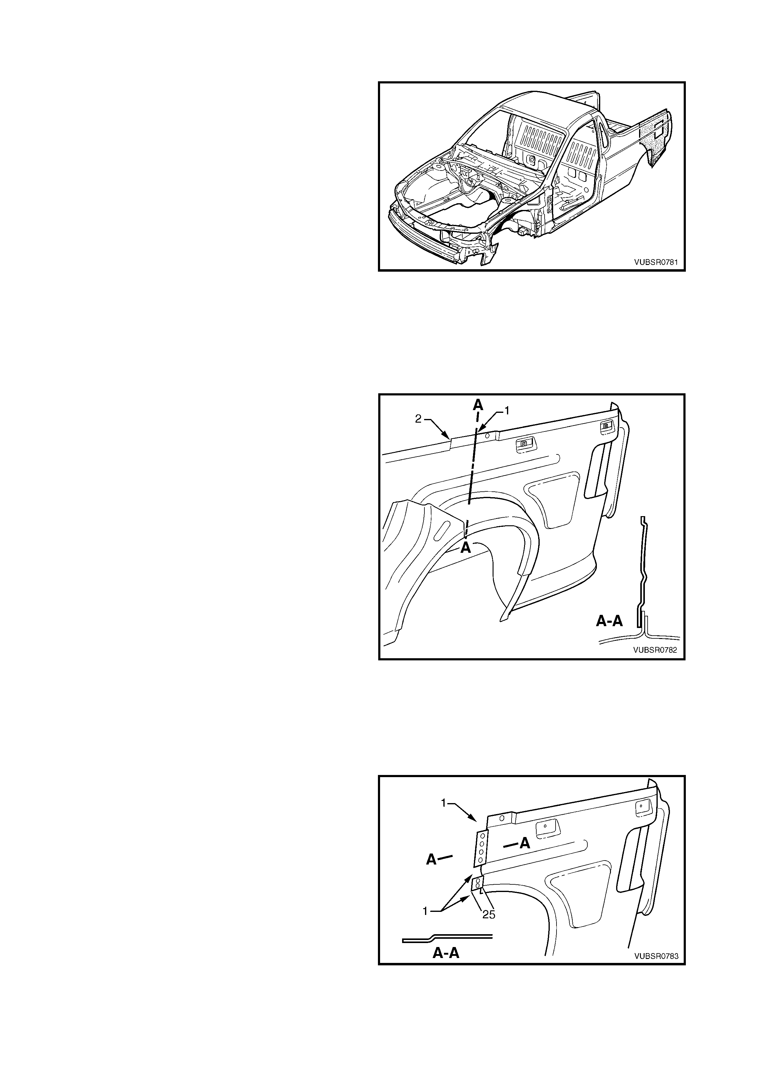
2.15 SIDE INNER UPPER PANEL – PARTIAL REPLACE
The following procedure allows partial replacement of
a rear sec tion of the side inner upper panel without the
need to replace the door opening frame assembly.
REMOVE
1. Remove the adjacent bolt-on panels and
components as described in the appropriate
Section of the MY 2003 VY & V2 Series II Service
Information.
2. Rem ove the rear quarter panel, refer to 2.1 REAR
QUARTER PANEL – REPLACE.
3. Remove the quarter outer lower rear panel, refer to
2.4 QUARTER OUTER LOWER REAR PANEL –
REPLACE.
4. Remove the quarter inner lower rear extension,
refer to 2.3 QUARTER INNER LOWER REAR
EXTENSION – REPLACE.
5. Remove the quarter inner & rear wheelhouse
brace, refer to 2.12 QUARTER INNER & REAR
WHEELHOUSE BRACE – REPLACE.
Figure 7C-144
6. Cut through the side inner upper panel (1)
approximately central within the joggle (2) for the
quarter inner & rear wheelhouse brace.
7. Remove the welds attaching the rear sec tion of the
side inner upper panel by referring to 2.14 SIDE
INNER UPPER PANEL – REPLACE.
8. Remove the partial panel and repair any damage
to the surrounding area as required.
Figure 7C-145
REPLACE
NOTE 1: Spot welding is the preferred method for attaching of panels and should be used whenever possible.
Where the spot welding equipment will not access the required weld position, a plug weld should be performed.
NOTE 2: The same number and position of s pot welds ( or plug welds) s hould be used when replacing the panel,
as was used during manufacture, in order to maintain the original structural strength of the vehicle.
1. Accurately measure and cut the replacement side
inner upper panel section from a new panel. Allow
a further 25mm for a joggle.
2. Remove the areas (1) and joggle the remaining
area towards the outer side of the vehicle.
3. Mark the new panel and the joggle with drilling
locations in preparation for plug welding as
required. Mar k the holes at a m axim um s pacing of
35 mm. Drill holes as marked.
4. Prepare all mating surfaces and treat with Weld
Through Primer (Item 1) as required, refer to
5. BODY SEALING, ADHESIVES & DEADENERS
in Section 3C.
Figure 7C-146
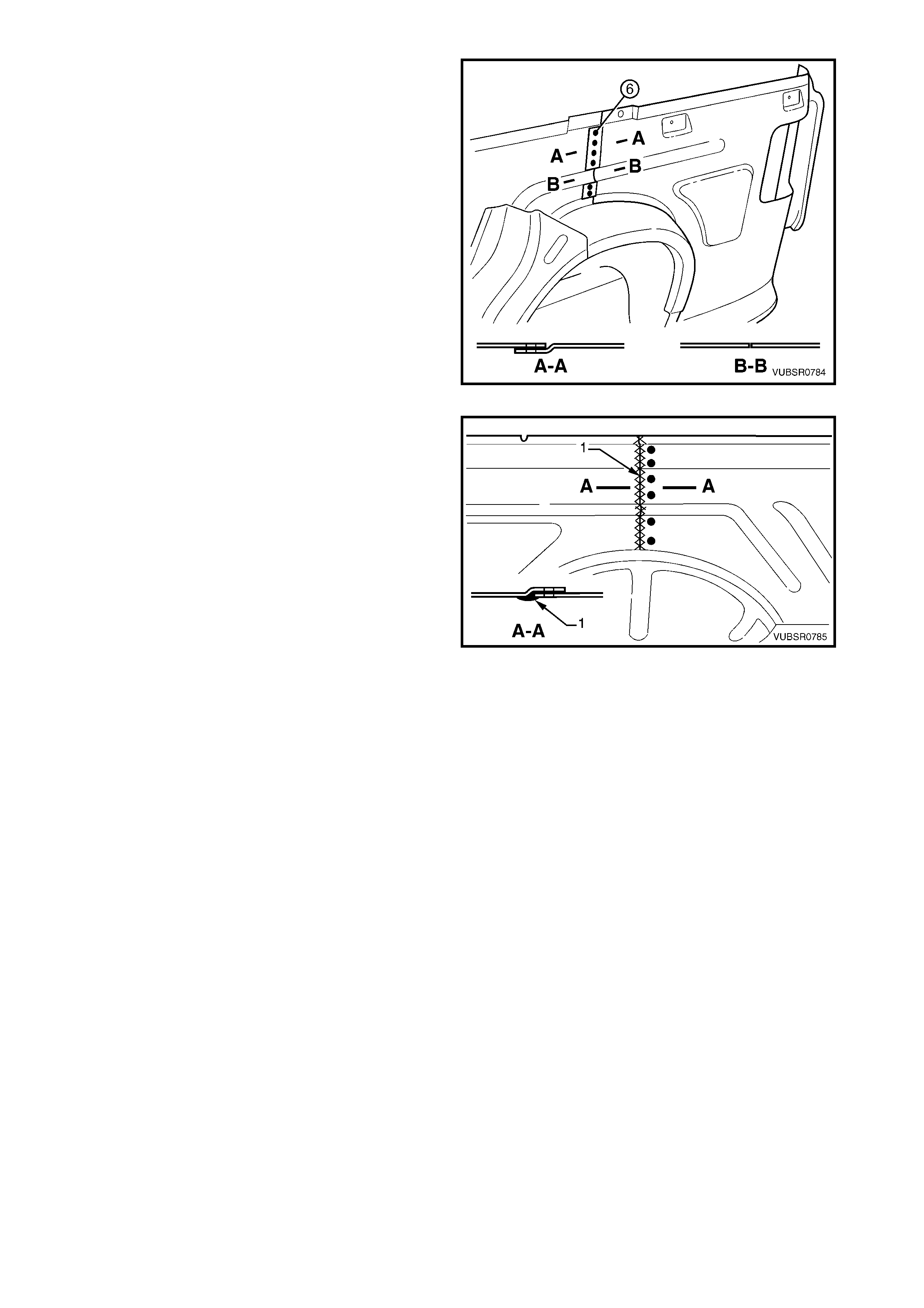
5. Fit and clamp the replacement section in position
on the vehicle ensuring the j oggle is located on the
outer side of the side inner upper panel and the
notched out areas butt to the original section.
6. Spot or plug weld the replacement section along
the joggle.
7. W eld the replacement section to the vehicle using
the appropriate procedures in 2.13 SIDE INNER
UPPER PANEL – REPLACE.
Figure 7C-147
8. Complete the joint by MIG welding (1) on the inner
side of the side inner upper panel.
9. Grind the weld to achieve a smooth finish. Do not
remove the surrounding metal. Finish as required.
10. Clean up and prime areas that will be covered by
the quarter inner & rear wheelhouse brace.
11. Install the quarter inner & rear wheelhouse brace,
refer to 2.12 QUARTER INNER & REAR
WHEELHOUSE BRA CE - REPLACE.
12. Install the quarter inner lower rear extension, refer
to 2.3 QUARTER INNER LOWER REAR
EXTENSION – REPLACE.
13. Install the cargo tie-down bracket (1) and cargo tie-
down bracket anchor plate as required, refer to
2.14 SIDE INNER UPPER PANEL – REPLACE.
Figure 7C-148
14. Clean up and prime areas that will be covered by the rear quarter panel.
15. Install the rear quarter panel, refer to 2.1 REAR QUARTER PANEL – REPLACE.
16. Refinish and paint panels and other components as required. Refer to Section 3, 1.3 PAINT REFINISHING.
17. Apply Joint Sealer (Item 3) as required. Refer to 5. BODY SEALING, ADHESIVES & DEADENERS in
Section 3C.
18. Apply Cavity W ax (Item 8) as required to the ins ide of any box s ections or areas inacces sible to paint, refer
to 6. CAVITY WAX in Section 3C.
19. Apply Spray-on Deadener (Item 7) to the wheel side of the rear wheelhouse as required, refer to
5. BODY SEALING, ADHESIVES & DEADENERS in Section 3C.
20. Install the rem aining c om ponents, ref er to the appr opriate Section of the MY 2003 VY & V2 Series II Service
Information.
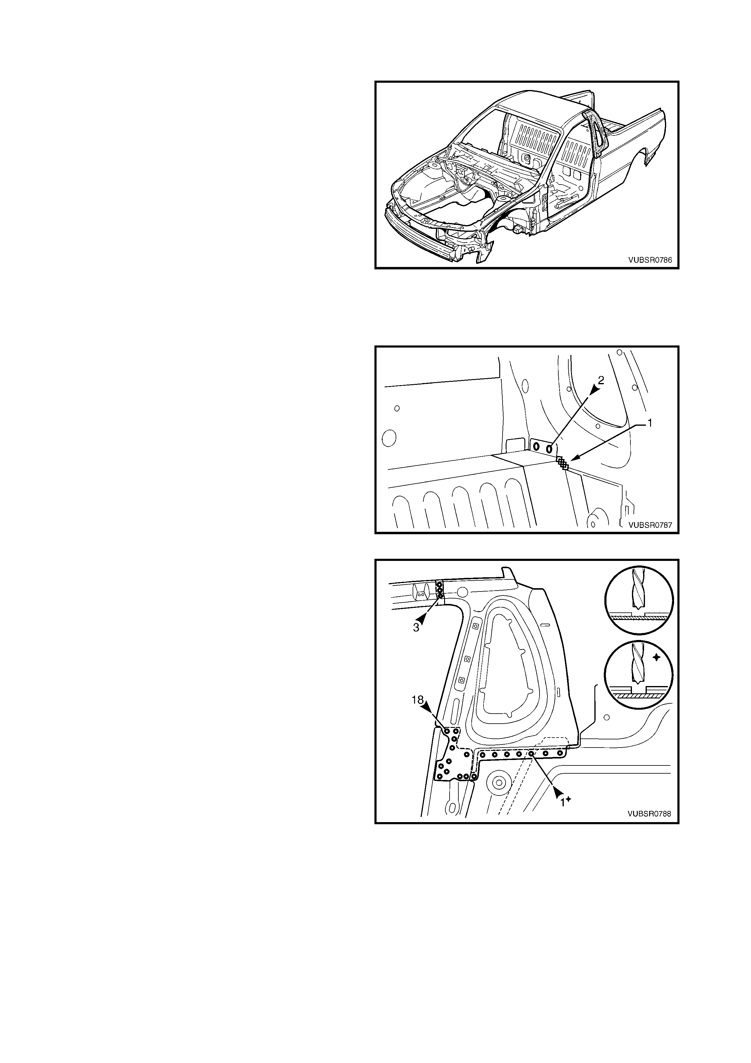
2.16 SIDE INNER UPPER FRONT PANEL – REPLACE
NOTE: This procedure includes the seatbelt guide
anchor plate assembly.
REMOVE
1. Remove the adjacent bolt-on panels and
components as described in the appropriate
Section of the MY 2003 VY & V2 Series II Service
Information.
2. Mount the vehicle on a suitable jig to maintain
correct body alignment when the panels are
removed.
3. Remove the roof panel, refer to Section 9, ROOF.
4. Rem ove the rear quarter panel, refer to 2.1 REAR
QUARTER PANEL – REPLACE.
5. Remove the door opening frame assembly, refer
to 2.6 DOOR OPENING FRAME ASSEMBLY –
REPLACE.
Figure 7C-149
6. Spot cut the welds and grind off the MIG weld (1)
attaching the side inner upper front panel to the
front seatback panel outer.
Figure 7C-150
7. Spot cut the welds attaching the side inner upper
front panel to the:
- Quarter panel inner extension roof three
places,
- Quarter panel inner assembly & side inner
upper panel 17 places,
- Front seatback panel outer & side inner upper
panel one place.
8. As required, remove any remaining welds
attaching the side inner upper f ront panel that may
not have been completely cut through during
removal of adjacent panels.
9. Remove the side inner upper front panel and
repair any damage to the surrounding areas as
required.
Figure 7C-151
REPLACE
NOTE 1: Spot welding is the preferred method for attaching of panels and should be used whenever possible.
Where the spot welding equipment will not access the required weld position, a plug weld should be performed.
NOTE 2: The same number and position of s pot welds ( or plug welds) s hould be used when replacing the panel,
as was used during manufacture, in order to maintain the original structural strength of the vehicle.
1. Mark the new panel and drill holes in preparation for plug welding where required.
2. Prepare all mating surfaces and treat with Weld Through Primer (Item 1) as required, refer to
5. BODY SEALING, ADHESIVES & DEADENERS in Section 3C.
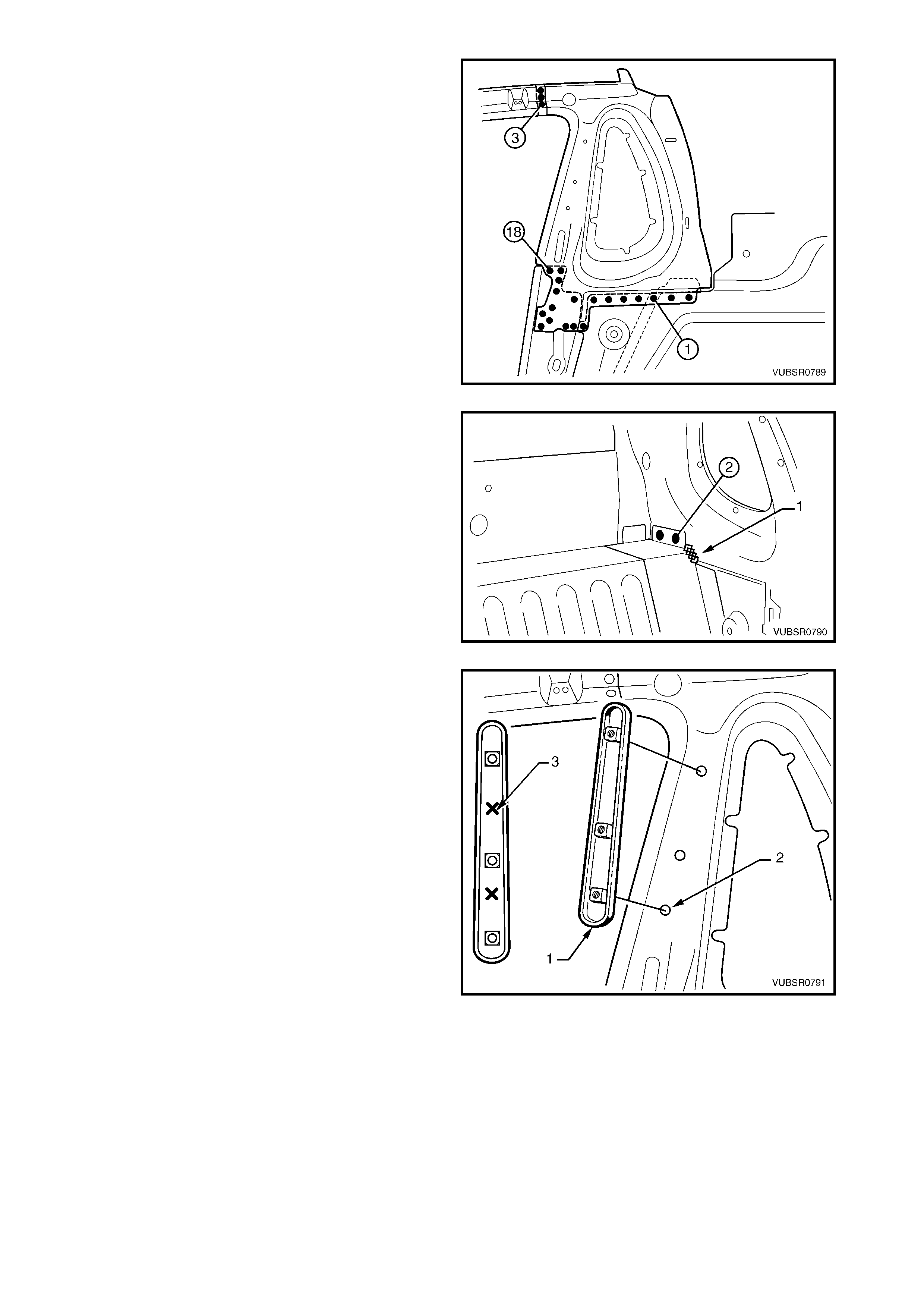
3. Spot or plug weld the side inner upper front panel
to the:
- Quarter panel inner extension three places,
- Quarter panel inner assembly & side inner
upper panel 17 places,
- Front seatback panel outer & side inner upper
panel one place.
Figure 7C-152
4. Spot or plug weld the fr ont seatback panel outer to
the side inner upper front panel.
5. MIG weld (1) 25 mm the front seatback panel
outer to the side inner upper front panel.
Figure 7C-153
6. Locate the seatbelt guide anchor plate assembly
(1) over the seatbelt mounting bolt holes (2) as
shown.
7. Spot or plug weld the seatbelt guide anchor plate
assembly to the side inner upper front panel, two
places (3).
8. Clean up and prime areas that will be covered by
the following panels.
9. Install the door opening frame assembly refer to
2.6 DOOR OPENING FRAME ASSEMBLY –
REPLACE.
10. Install the roof panel, refer to Section 9, ROOF.
11. Install the rear quarter panel, refer to 2.1 REAR
QUARTER PANEL – REPLACE.
12. Refinish and paint panels and other components
as required. Refer to Section 3, 1.3 PAINT
REFINISHING.
13. Apply Joint Sealer (Item 3) as required. Refer to
5. BODY SEALING, ADHESIVES & DEADENERS
in Section 3C.
14. Apply Cavity Wax (Item 8) as requir ed to the inside
of any box sections or areas inaccessible to paint,
refer to 6. CAVITY WAX in Section 3C.
Figure 7C-154
15. Install the remaining components as described in
the appropriate Section of the MY 2003 VY & V2
Series II Service Information.
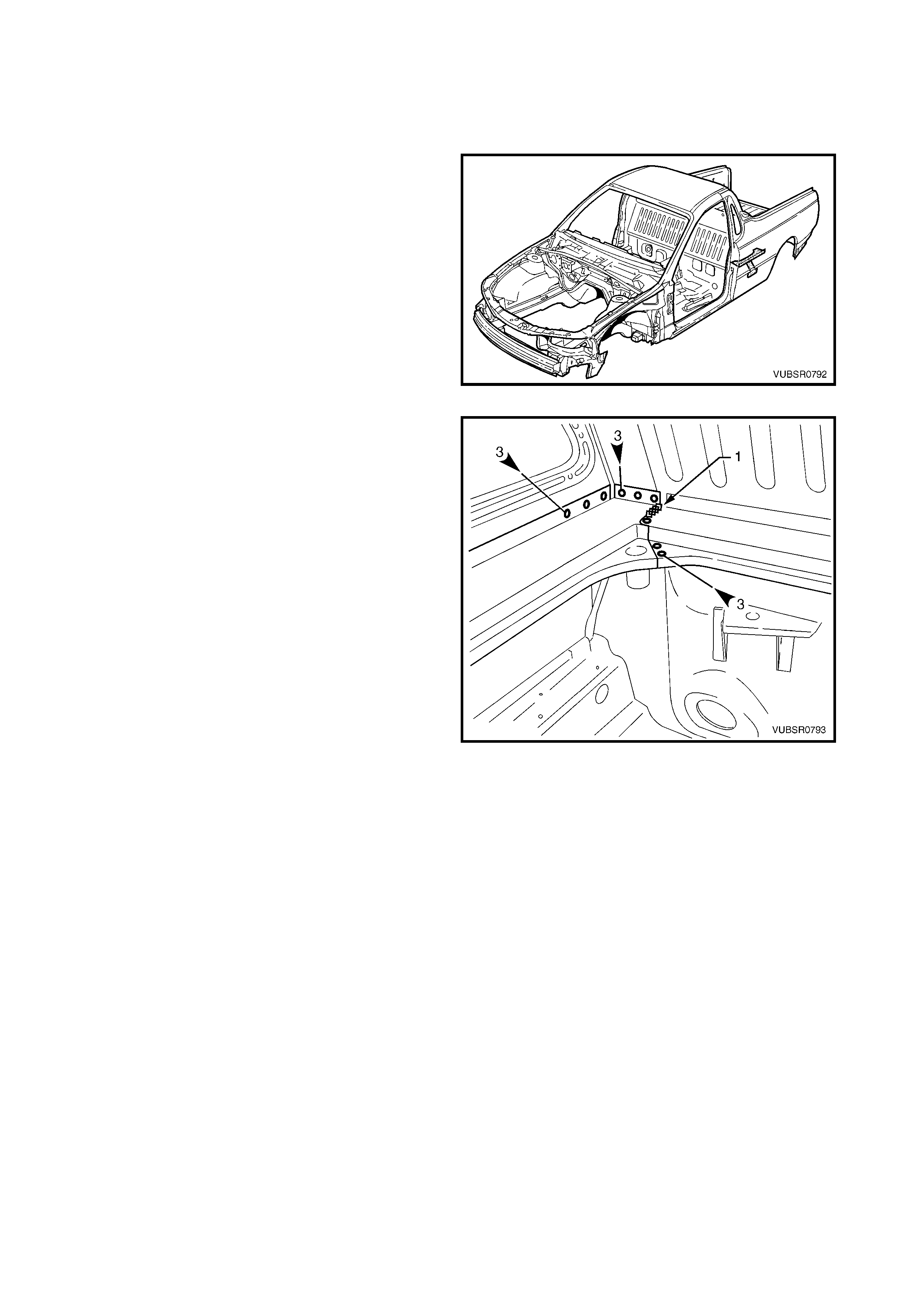
2.17 LOAD FLOOR PANEL OUTER EXTENSION & LOAD FLOOR PANEL
OUTER REINFORCEMENT – REPLACE
REMOVE
1. Remove the adjacent bolt-on panels and
components as described in the appropriate
Section of the MY 2003 VY & V2 Series II Service
Information.
2. Remove the adjacent panels as required, refer to
the relevant Section in this Supplement.
Figure 7C-155
3. Spot cut the welds attaching the load floor panel
outer extension to the s ide inner upper panel three
places, the f ront seatbac k panel outer three places
and the front seatback panel three places.
4. Grind off the MIG weld (1) attaching the load floor
panel outer extension to the front seatback panel.
Figure 7C-156
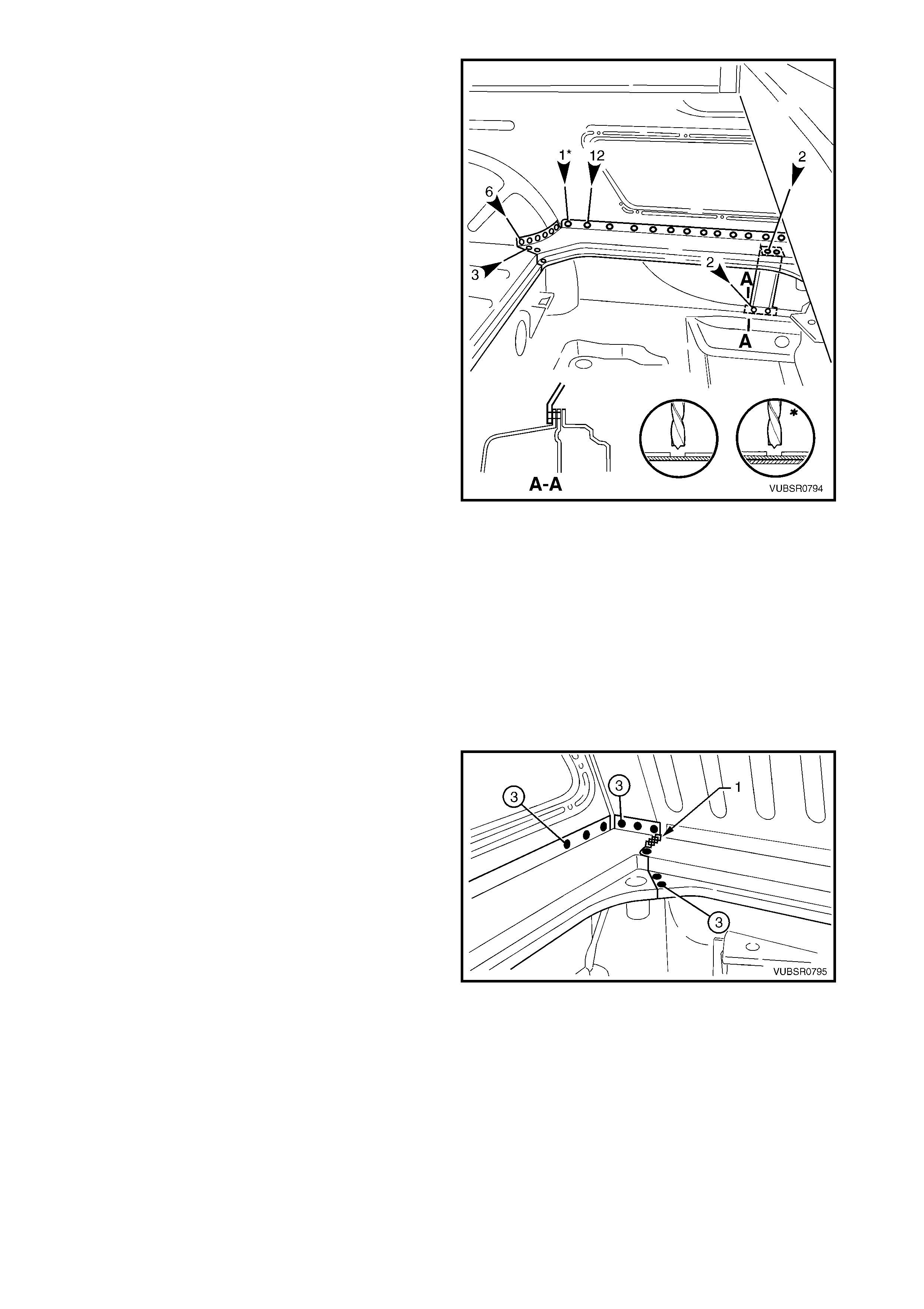
5. Spot cut the welds attaching the load floor panel
outer extension to the load floor panel outer
reinforcement two places.
6. Spot cut the welds attaching the load floor panel
outer extension to the side inner upper panel
twelve places, the rear wheelhouse inner panel
and side inner upper panel one place, the rear
wheelhouse inner panel six places and the load
floor panel three places.
7. Remove the load floor panel outer extension from
the vehicle.
8. If required, spot cut the welds attaching the load
floor panel outer r einf or cement to the door opening
frame assembly two places and remove the
reinforcement.
NOTE: The spot welds are not visible from the inside
of the vehicle. If the rear quarter panel is not removed
cut the welds with a saw or chisel.
Figure 7C-157
REPLACE
NOTE 1: Spot welding is the preferred method for attaching of panels and should be used whenever possible.
Where the spot welding equipment will not access the required weld position, a plug weld should be performed.
NOTE 2: The same number and position of s pot welds ( or plug welds) s hould be used when replacing the panel,
as was used during manufacture, in order to maintain the original structural strength of the vehicle.
1. Mark the new panel and drill holes in preparation for plug welding where required.
2. Prepare all mating surfaces and treat with Weld Through Primer (Item 1) as required, refer to
5. BODY SEALING, ADHESIVES & DEADENERS in Section 3C.
3. Apply Structural Adhesive (Item 6) to the load floor panel mating surface (1, Figure-159), refer to
5. BODY SEALING, ADHESIVES & DEADENERS in Section 3C.
4. Clamp the load floor panel outer extension in
position and spot or plug weld to the front seatback
panel outer three places and the front seatback
panel three places.
5. MIG weld (1) 25 mm the to the front seatback
panel.
6. Spot or plug weld side the load floor panel outer
extension to the side inner upper panel 3 places.
Figure 7C-158
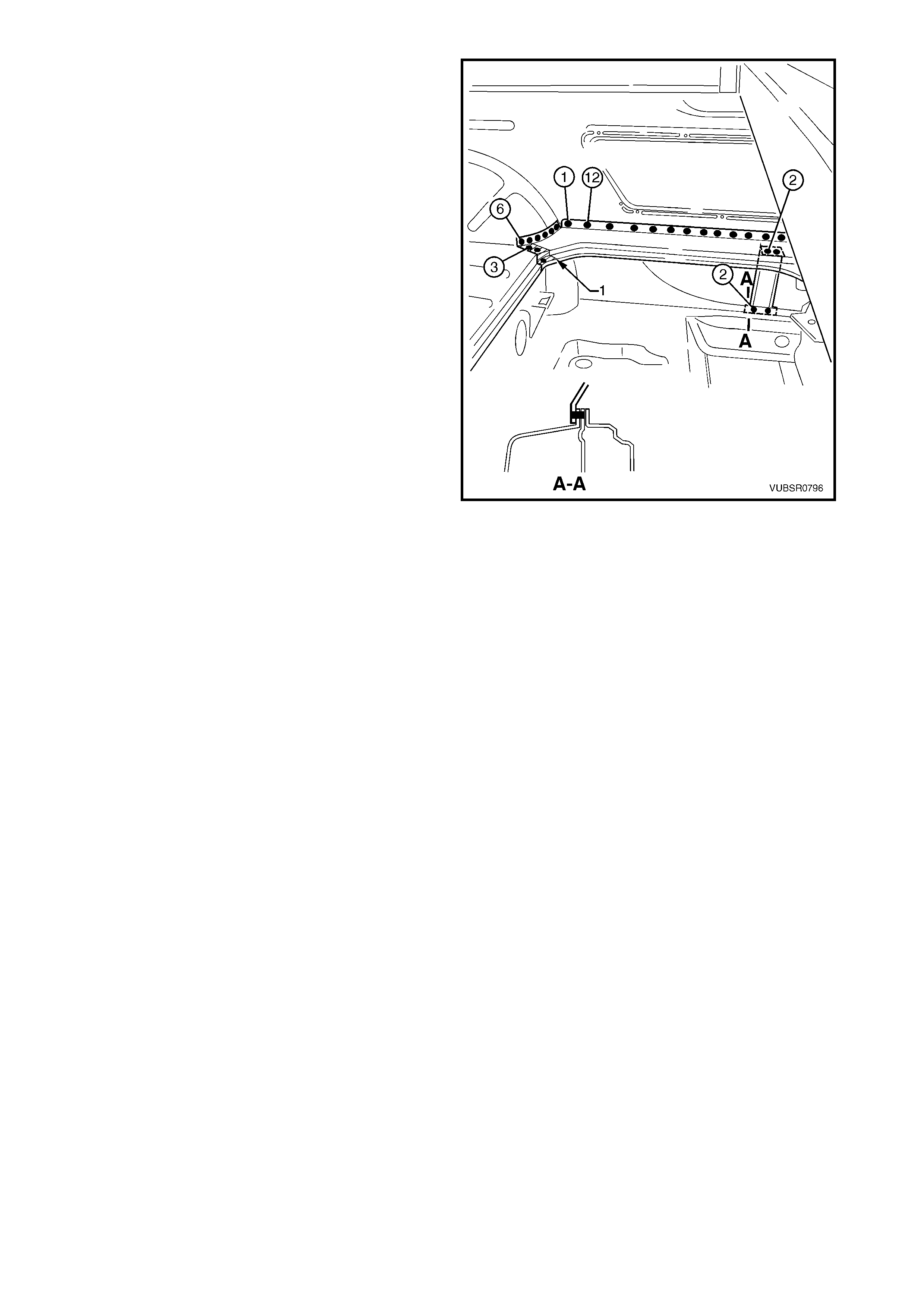
7. Spot or plug weld the load floor panel outer
extension to the side inner upper panel twelve
places.
8. Spot or plug weld the extension to the rear
wheelhouse inner panel and side inner upper
panel 1 place.
9. Spot or plug weld the extension to the rear
wheelhouse inner panel six places and the load
floor panel three places.
10. If removed, spot or plug weld the load floor panel
outer reinforcement to the lower flange two places.
NOTE: If the rear quarter panel was not rem oved, drill
through the flange from the inside and plug weld
through the flange.
11. Spot or plug weld the reinforcement to the
extension two places.
12. Install any other rem oved panels as requir ed, refer
to the appropriate Section of this Supplement.
13. Refinish and paint panels and other components
as required. Refer to Section 3, 1.3 PAINT
REFINISHING.
14. Apply Joint Sealer (Item 3) as required. Refer to
5. BODY SEALING, ADHESIVES & DEADENERS
in Section 3C.
15. Apply Cavity Wax (Item 8) as requir ed to the inside
of any box sections or areas inaccessible to paint,
refer to 6. CAVITY WAX in Section 3C.
16. Install the remaining components as described in
the appropriate Section of the MY 2003 VY & V2
Series II Service Information.
Figure 7C-159
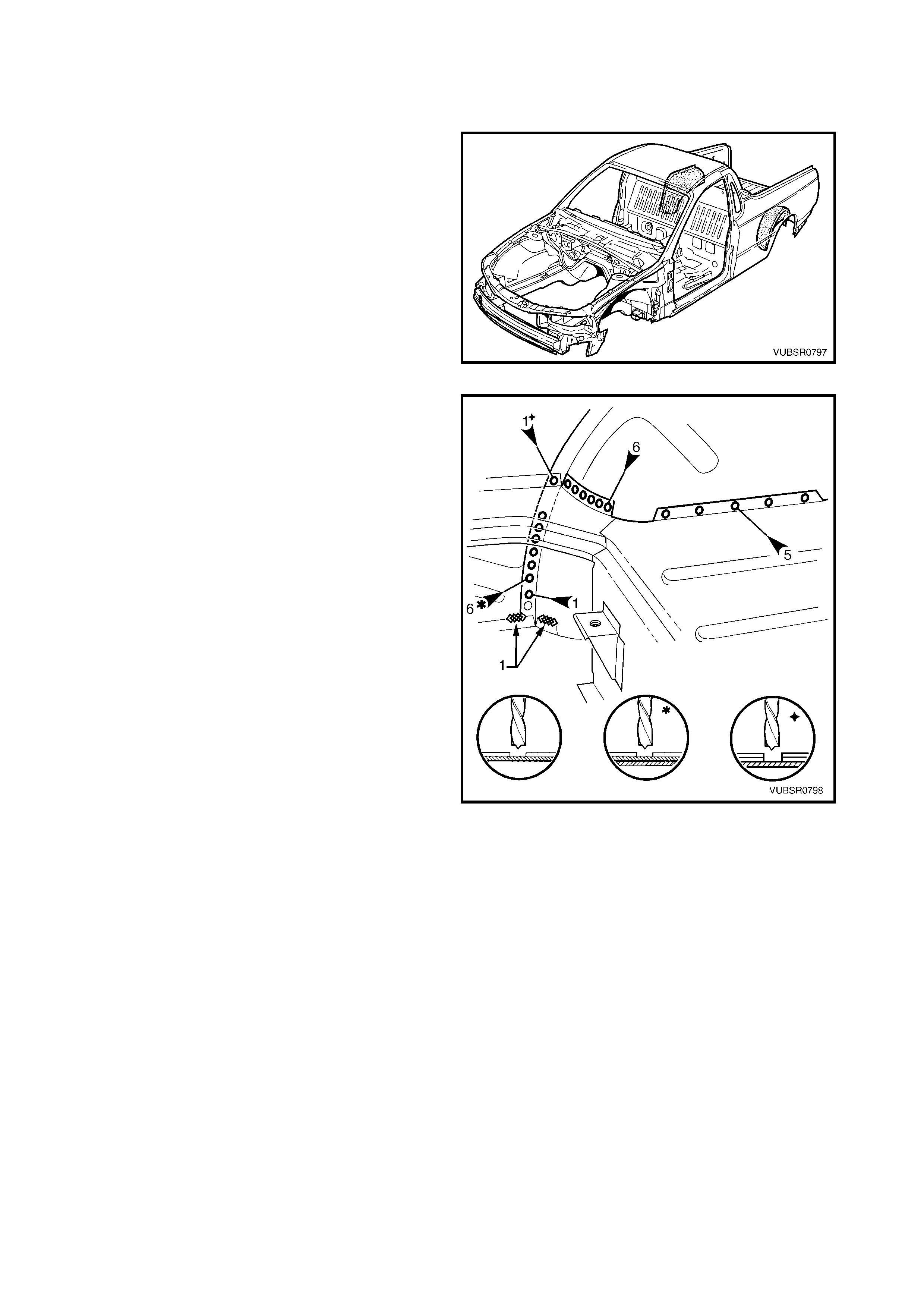
2.18 REAR WHEELHOUSE INNER PANEL – REPLACE
REMOVE
1. Remove the adjacent bolt-on panels and
components as described in the appropriate
Section of the MY 2003 VY & V2 Series II Service
Information.
2. Remove the adjacent panels as required, refer to
the relevant Section in this Supplement.
Figure 7C-160
3. Grind off the MIG welds (1) attaching the rear floor
panel assembly to the rear wheelhouse inner
panel.
4. Spot cut the welds attaching the rear wheelhouse
inner panel to the quarter panel inner assembly
and side inner upper panel six places.
5. Spot cut the weld attaching the load floor outer
extension to the rear wheelhouse inner panel and
side inner upper panel one place.
6. Spot cut the welds attaching the load floor outer
extension to the rear wheelhouse inner panel six
places.
7. Spot cut the welds attac hing the load floor panel to
the rear wheelhouse inner panel five places.
8. Grind off the MIG weld (1) attaching the load floor
panel to the rear wheelhouse inner panel and side
inner upper panel, refer to Figure 7C-162.
9. For the left-hand s ide, spot cut the welds attaching
rear wheelhouse inner panel to the side inner
upper panel and quarter panel inner assembly, 18
places, refer to Figure 7C-162.
10. For the right-hand side, spot cut the welds
attaching rear wheelhouse inner panel to the side
inner upper panel and quarter panel inner
assembly, 12 places and the side inner upper
panel and rear wheelhouse outer extension 12
places, refer to Figure 7C-162.
Figure 7C-161

Figure 7C-162
11. Spot cut the welds attaching the rear wheelhouse
inner panel to the load floor panel, 5 plac es on the
left-hand side or 10 places on the right-hand side.
12. As required, spot cut the welds attaching the rear
wheelhouse bracket to the rear wheelhouse inner
panel and quarter panel inner assembly.
13. If the rear quarter panel and door opening frame
assembly have been removed, spot cut the three
welds (1) attaching the quarter panel inner
assembly to the wheelhouse inner, refer to Figure
7C-164.
NOTE: If the panels have not been r emoved, cut along
the line (2) and across the flange on the inside of the
vehicle to detach this piece.
14. Spot cut the welds attaching the quarter panel
inner assembly and door opening frame assembly
to the rear wheelhouse inner panel, two places,
refer to Figure 7C-164.
15. Spot cut the welds attaching the rear wheelhouse
inner panel to the inner rock er panel, three places ,
refer to Figure 7C-164.
Figure 7C-163
16. Spot cut the welds attaching the rear wheelhouse
inner panel to the load floor panel and rear floor
panel assembly, 23 places, refer to Figure 7C-164.
17. Remove the rear wheelhouse inner panel and
repair any damage to the surrounding areas as
required.
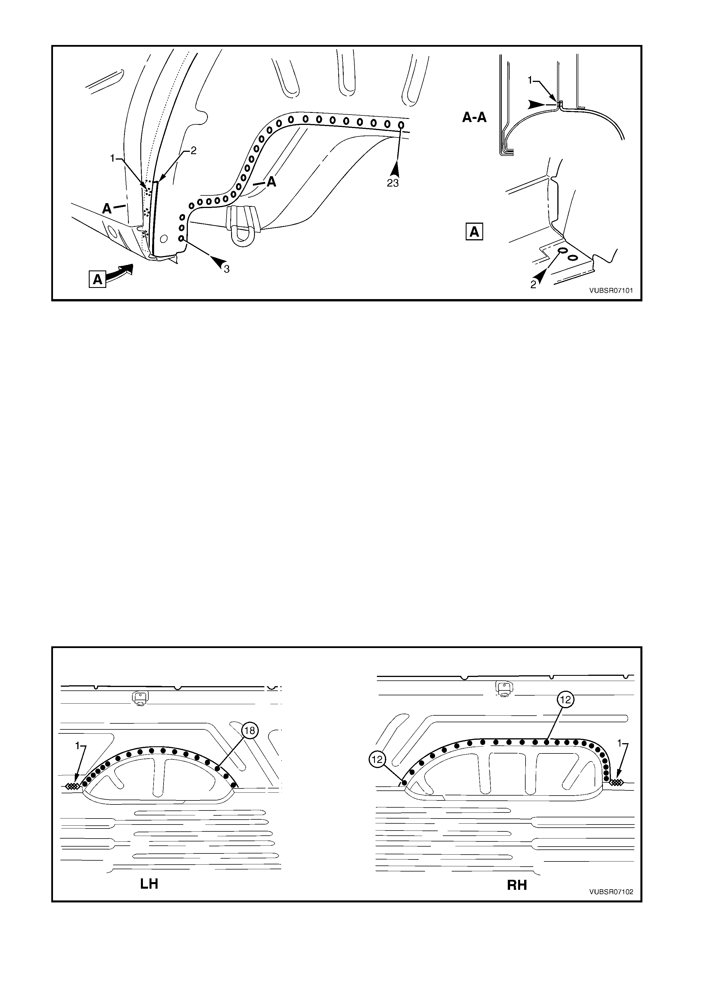
Figure 7C-164
REPLACE
NOTE 1: Spot welding is the preferred method for attaching of panels and should be used whenever possible.
Where the spot welding equipment will not access the required weld position, a plug weld should be performed.
NOTE 2: The same number and position of s pot welds ( or plug welds) s hould be used when replacing the panel,
as was used during manufacture, in order to maintain the original structural strength of the vehicle.
1. Mark the new panel and drill holes in preparation for plug welding where required.
2. Prepare all mating surfaces and treat with Weld Through Primer (Item 1) as required, refer to
5. BODY SEALING, ADHESIVES & DEADENERS in Section 3C.
3. If the front piece of the rear wheelhouse was cut off, remove a corresponding piece from the replacement
panel.
4. Apply Structural Adhesive (Item 6) to the rear wheelhouse inner panel (3, Figure 7C-167), refer to
5. BODY SEALING, ADHESIVES & DEADENERS in Section 3C.
5. Clamp the rear wheelhouse inner panel in position on the vehicle.
6. For the left-hand side, spot or plug weld the rear wheelhouse inner panel to the quarter panel inner assembly
and side inner upper panel, 18 places, refer to Figure 7C-165.
7. For the right-hand side, spot or plug weld the rear wheelhouse inner panel to the quarter panel inner
assem bly and side inner upper panel, 12 places and the side inner upper panel and rear wheelhouse outer
extension 12 places, refer to Figure 7C-165.
8. MIG weld 25 - 50m m (1) the load f loor panel to the rear wheelhouse inner panel and side inner upper panel,
refer to Figure 7C-165.
Figure 7C-165
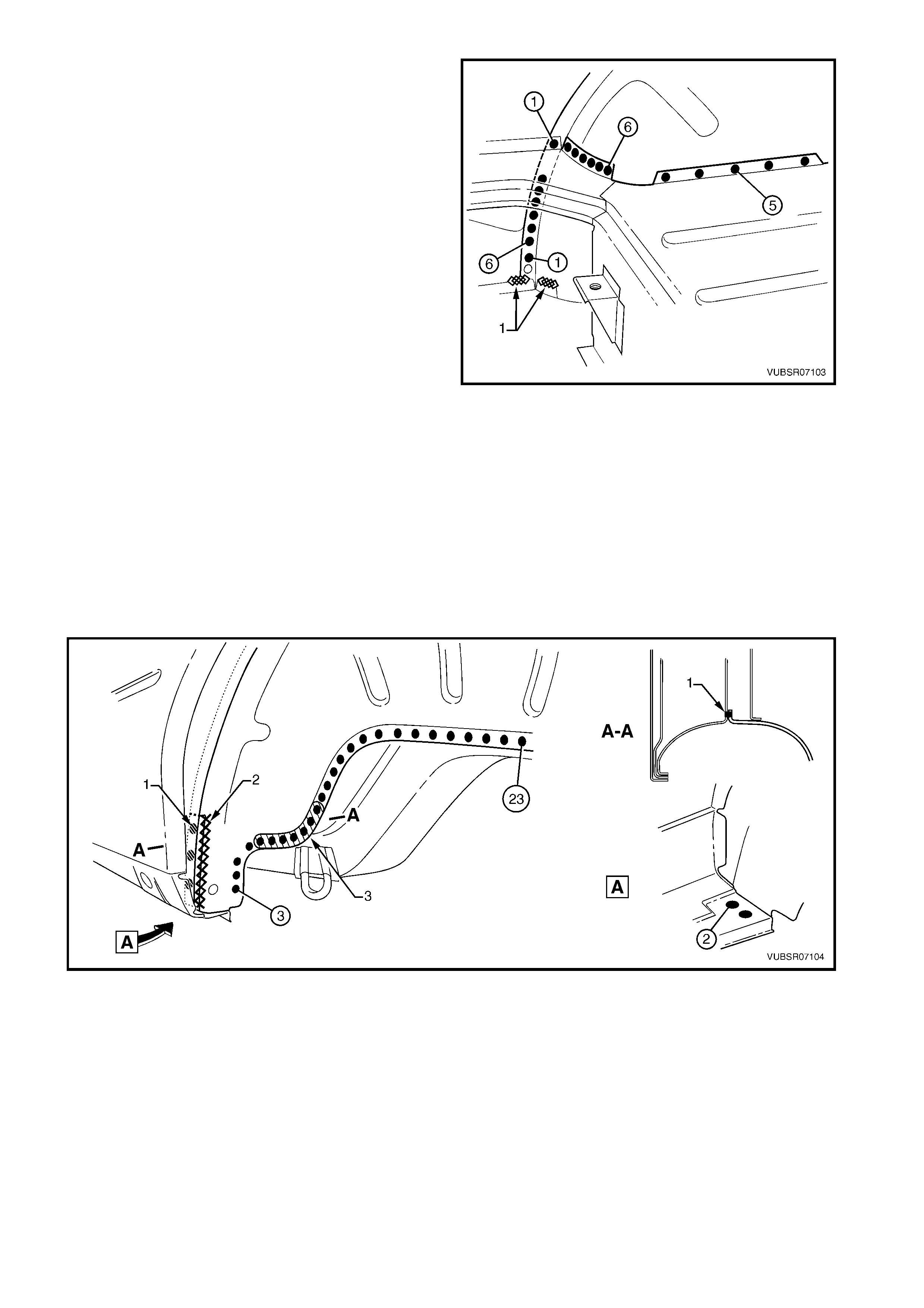
9. Spot or plug weld the load floor panel to the rear
wheelhouse inner panel five places.
10. Spot or plug weld the load floor outer extension to
the rear wheelhouse inner panel six places.
11. Spot or plug weld the load floor outer extension to
the rear wheelhouse inner panel and side inner
upper panel one place.
12. Spot or plug weld the rear wheelhouse inner panel
to the side inner upper panel and quarter panel
inner assembly six places.
13. MIG weld 25 mm (1) two places, the rear floor
panel assembly to the rear wheelhouse inner
panel.
14. If the rear quarter panel and door opening frame
assembly were removed, spot or plug weld (1)
three places the quarter panel inner assembly to
the rear wheelhouse inner panel, refer to Figure
7C-167.
NOTE: If the panels were not removed, MIG weld
along the cut (2) and ac ross the flange on the inside of
the vehicle.
15. Spot or plug weld the rear quarter panel and door
opening frame assembly to the rear wheelhouse
inner panel, two places, refer to Figure 7C-167.
16. Spot or plug weld the rear wheelhouse inner panel
to the inner rocker panel, three places, refer to
Figure 7C-167.
17. Spot or plug weld the rear wheelhouse inner panel
to the load floor panel and rear floor panel
assembly, 23 places, refer to Figure 7C-167.
Figure 7C-166
Figure 7C-167
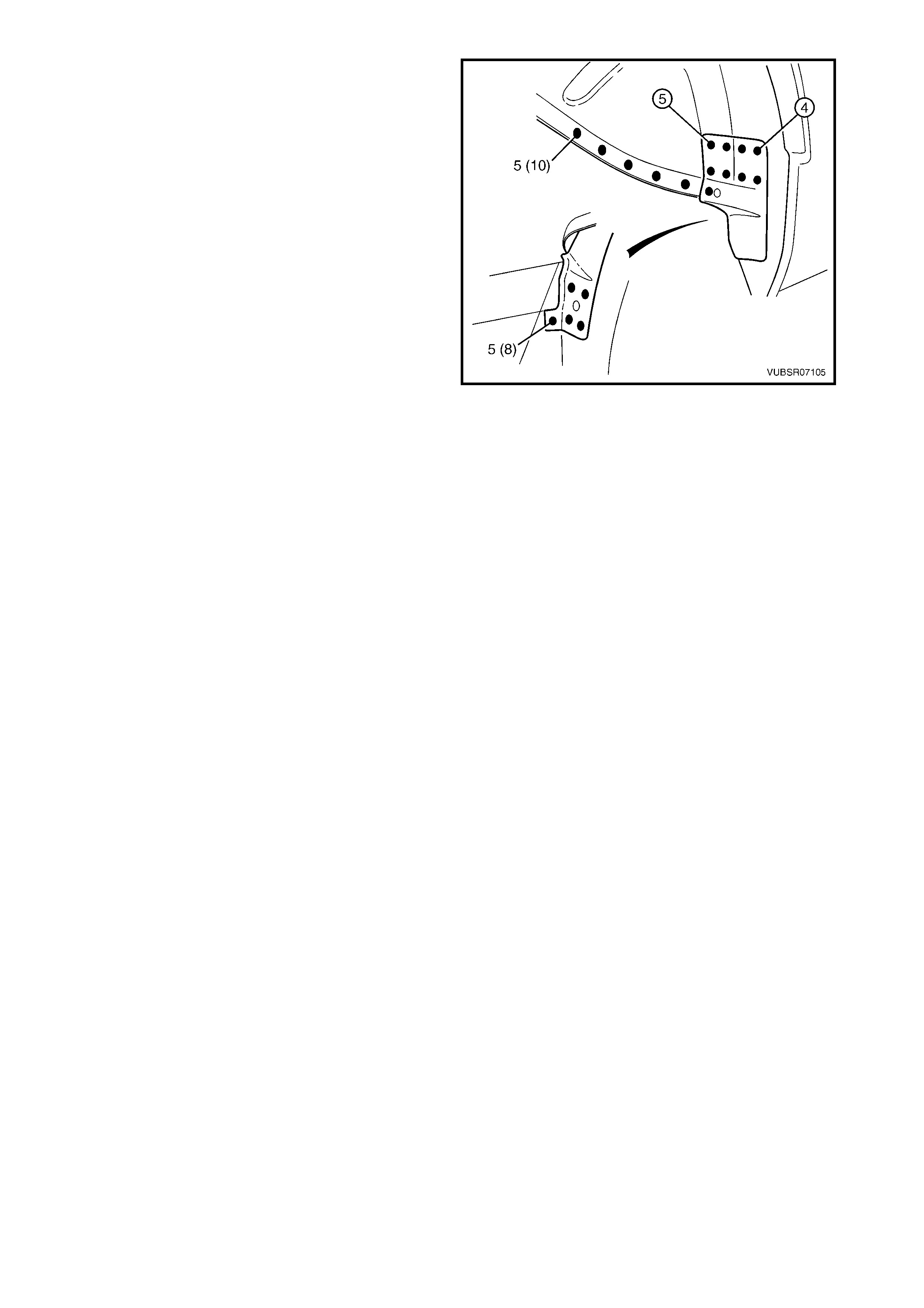
18. Spot or plug weld the rear wheelhouse inner panel
to the load floor panel, 5 places on the left-hand
side or 10 places on the right-hand side.
19. As r equired, s pot or plug weld the rear wheelhous e
bracket to the rear wheelhouse inner panel and
quarter panel inner assembly.
20. Install any other rem oved panels as requir ed, refer
to the appropriate Section of this Supplement.
21. Refinish and paint panels and other components
as required. Refer to Section 3, 1.3 PAINT
REFINISHING.
22. Apply Joint Sealer (Item 3) as required. Refer to
5. BODY SEALING, ADHESIVES & DEAD ENERS
in Section 3C.
23. Apply Cavity Wax (Item 8) as requir ed to the inside
of any box sections or areas inaccessible to paint,
refer to 6. CAVITY WAX in Section 3C.
24. Apply Spray-on deadener to the wheel side of the
rear wheelhouse panel, refer to 5. BODY
SEALING, ADHESIVES & DEADENERS in
Section 3C.
25. Install the remaining components as described in
the appropriate Section of the MY 2003 VY & V2
Series II Service Information.
Figure 7C-168