
SECTION 4H - VT SERIES 195 kW V8 ENGINE
CAUTION:
This vehicle will be equipped with a Supplemental Restraint System (SRS). A SRS will consist of
either seat belt pre-tension ers and a driver’s air bag , seat belt pre-t ensioners and a driv er’s and front
passenger’s air bag s or seat belt pre-tensio ners, driver’s and fron t passenger’s air bags and left and
right hand side air bags. Depending upon the system fitted, refer to SAFETY PRECAUTIONS, Section
12M Supplemental Restraint System in the VT Series I Service Information, before performing any
service operation on or around any SRS components, the steering mechanism or wiring. Failure to
follow the SAFETY PRECAUTIONS could result in SRS deployment, resulting in possible personal
injury or unnecessary SRS system repairs.
1. GENERAL INFORMATION
This Section of the Holden By Design Service Information Supplement describes the components employed in
the 195 kW V8 engine upgrade.
The 195 kW V8 engine has been developed by Holden Special Vehicles and includes mechanical revisions -
cylinder heads, camshaft, etc., a revised air inlet system and a new exhaust system. A recalibrated powertrain
management is also incorporated.
Together, these modifications increase the power output to 195 kW @ 4600 rpm and torque output to 430 Nm
@ 3800 rpm.
Mandatory with the 195 kW engine upgrade on Executive and Berlina models is the fitment of ‘V’ rated tyres.
A Holden By Design identification plate and 195i badging completes the package.
Figure 4H-1 illustrates the 195 kW V8 engine major components.
For information not contained in this Section, refer to: Section 6A2, V8 ENGINE in the VT Series I Service
Information, Section 6C2 POWERTRAIN MANAGEMENT-V8 ENGINE in the VT Series I Service Information,
Section 10 WHEELS & TYRES in the VT Series I Service Information.
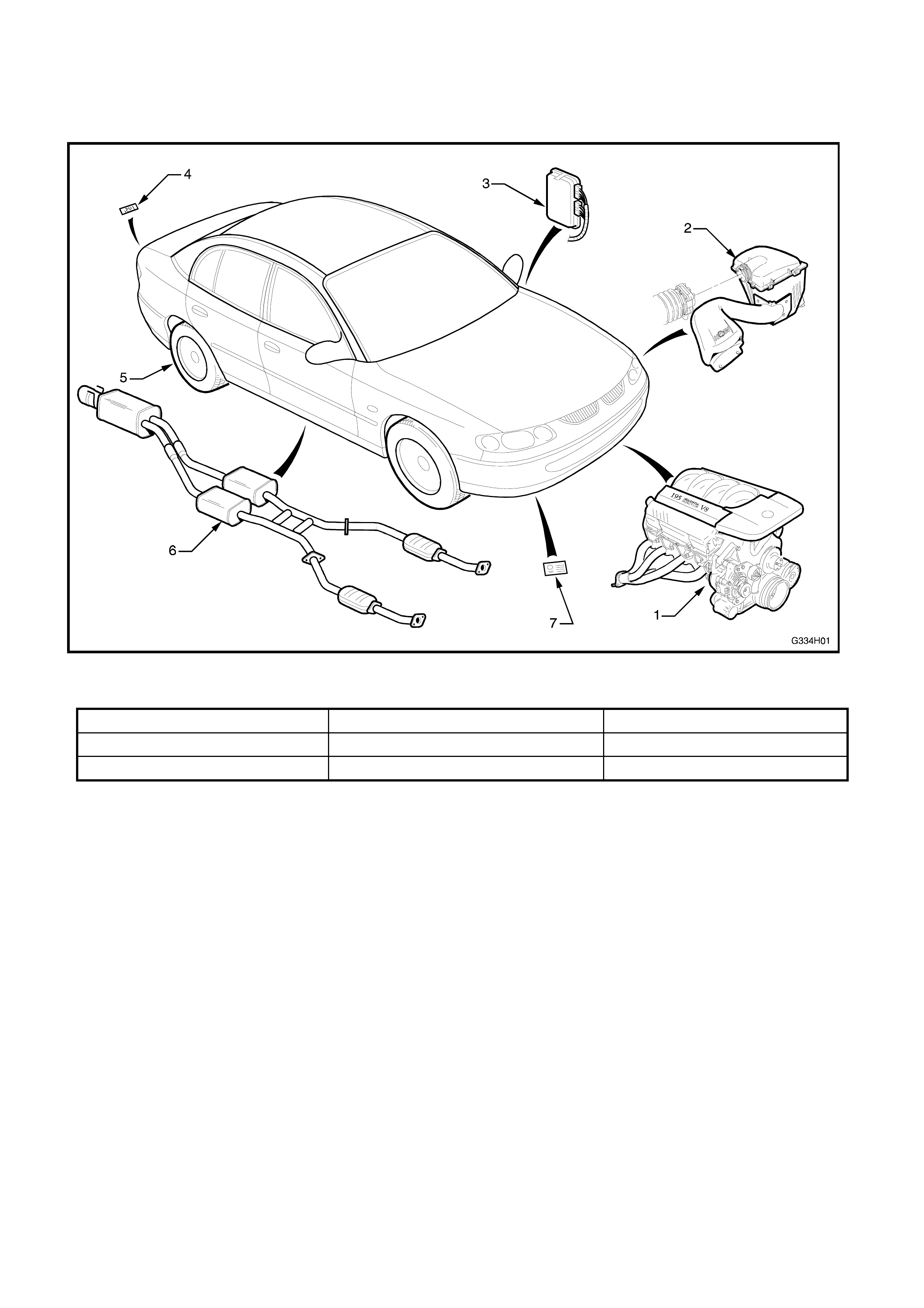
1.1 MAJOR COMPONENTS
Figure 4H-1
1. Engine assembly 4. 195i emblem 7. HBD identification plate
2. Air inlet assembly 5. V-Rated tyres
3. PCM 6. Exhaust system
2. ENGINE
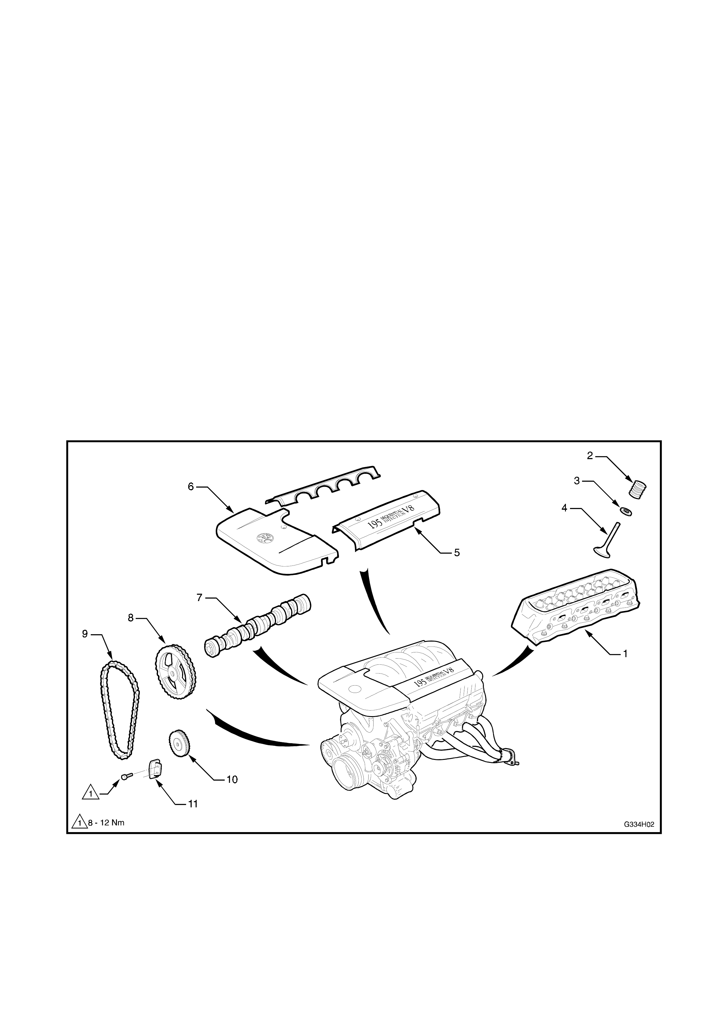
The com ponents fitted to the 195 kW V8 engine that differ to the standard Holden V8, as shown in Figure 4H- 2,
are:
• Cylinder head (1),
• Exhaust valve spring (2),
• Stainless steel valve spring seat (3),
• Exhaust valve (4),
• Fuel rail cover (5),
• Throttle body cover (6),
• High-lift, high-duration camshaft (7),
• Timing chain and steel sprockets (8-10),
• Timing chain damper (11).
The modifications are designed to improve the engine’s breathing and ensure it copes with the power increase.
The engine throttle body cover, rocker covers and fuel rail covers are coloured flame red. The fuel rail covers are
also fitted with ‘195 Sequential Injection V8’ labels.
195 kW V8 engines are identified by the engine option code LB9 & XX3, which is stamped into the vehicle
identification plate. Also, the engine number is prefixed by the letters VN. The engine number is located on the
LH side of the cylinder block above the oil pump housing.
The procedures and specifications required to service and repair the Holden By Design 195 kW V8 engine are
the same as for the standard VT Series Holden V8 engine, refer to Section 6A2,V8 ENGINE in the VT Ser ies I
Service Information, except for the camshaft specifications which are listed on the next page.
Figure 4H-2

195 KW V8 CAMSHAFT SPECIFICATIONS
HSV 195 kW V8 camshaft Part No. 06X-970301
Lobe lift 0.28”
Lobe duration: Inlet
Exhaust 268°
268°
Valve timing @ 0.050” valve lift:
Inlet open
close
Exhaust open
close
21° BTDC
67° ATDC
65° BTDC
23° ATDC
Duration @ 0.050” 206°
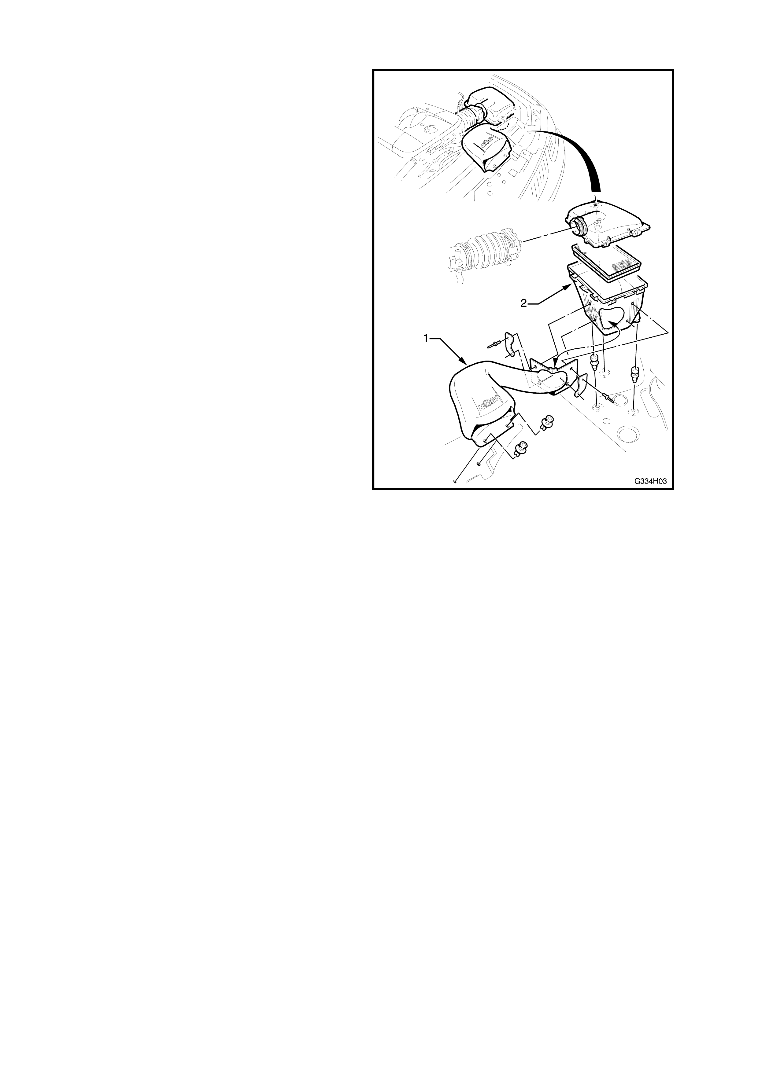
3. INLET SYSTEM
A newly designed cold-air inlet system, which has
been optimised for the 195 kW engine is fitted.
Changes from the standard air inlet system include a
free f low inlet snork el (1) and a revised airbox (2). All
other com ponents, including the air filter, ar e st andard
VT Series V8 components.
Service procedures are the same as the standard V8
engine inlet system. Refer to Section 6C2,
POWERTRAIN MANAGEMENT-V8 ENGINE in the
VT Series I Service Information.
Figure 4H-3
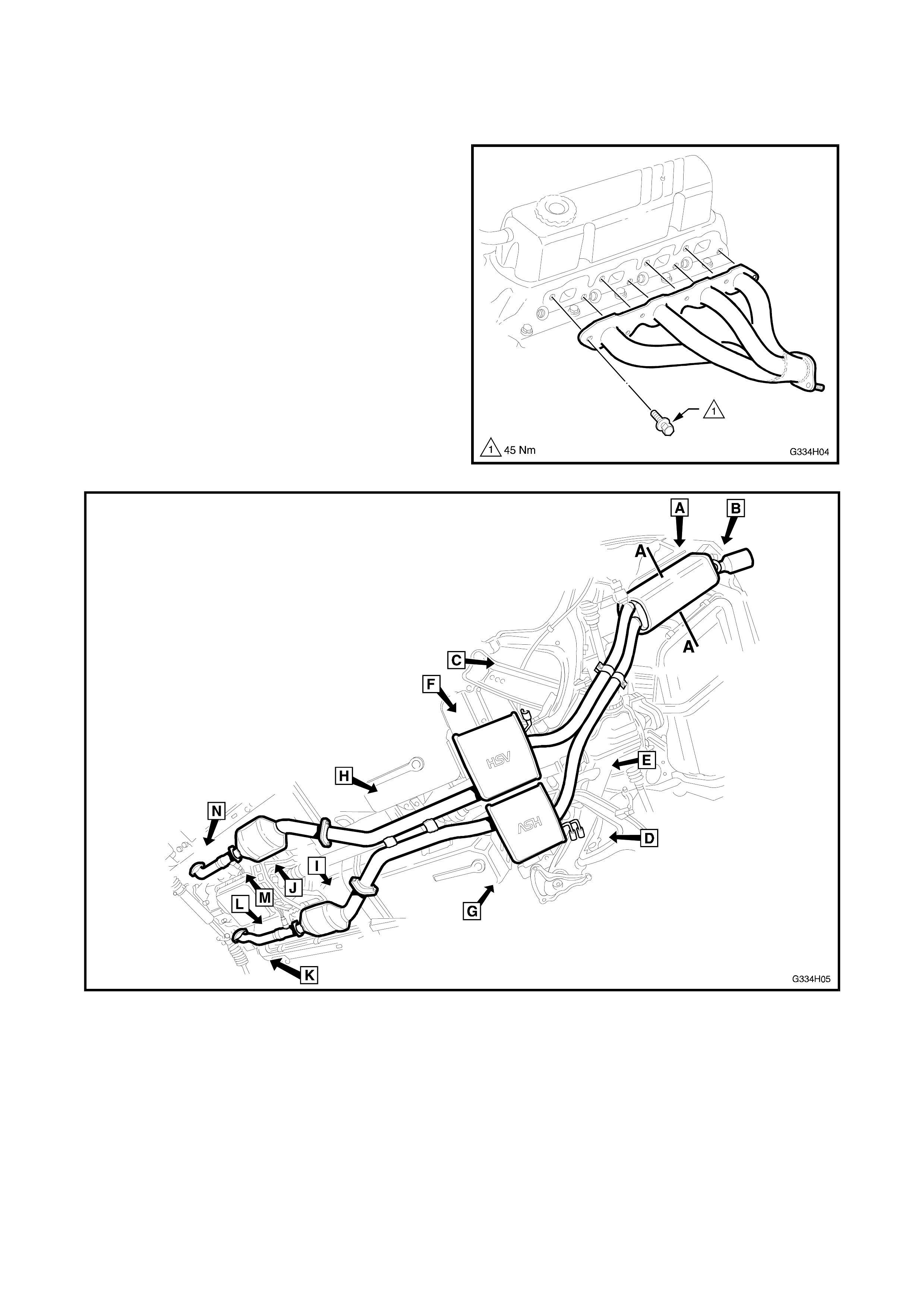
4. EXHAUST SYSTEM
A totally new exhaust system is used in place of the
standard VT exhaust. It is a low restriction, free
flowing system which reduces back-pressure and
improves engine breathing. Tubular header type
exhaust manifolds as shown in Figure 4H-4, replace
the standard engine’s cast iron manifold.
Due to different lengths in wheelbase between sedan
and wagon variants, the intermediate muffler
assembly’s front pipes are approximately 150 mm
longer for wagon.
Service proc edures f or the Holden By Des ign 195 k W
V8 exhaust system are the same as the standard VT
Series V8 exhaust system, refer to Section 8B,
EXHAUST SYSTEM in the VT Series I Service
Information, except for the clearances shown in the
following diagrams.
Figure 4H-4
Figure 4H-5
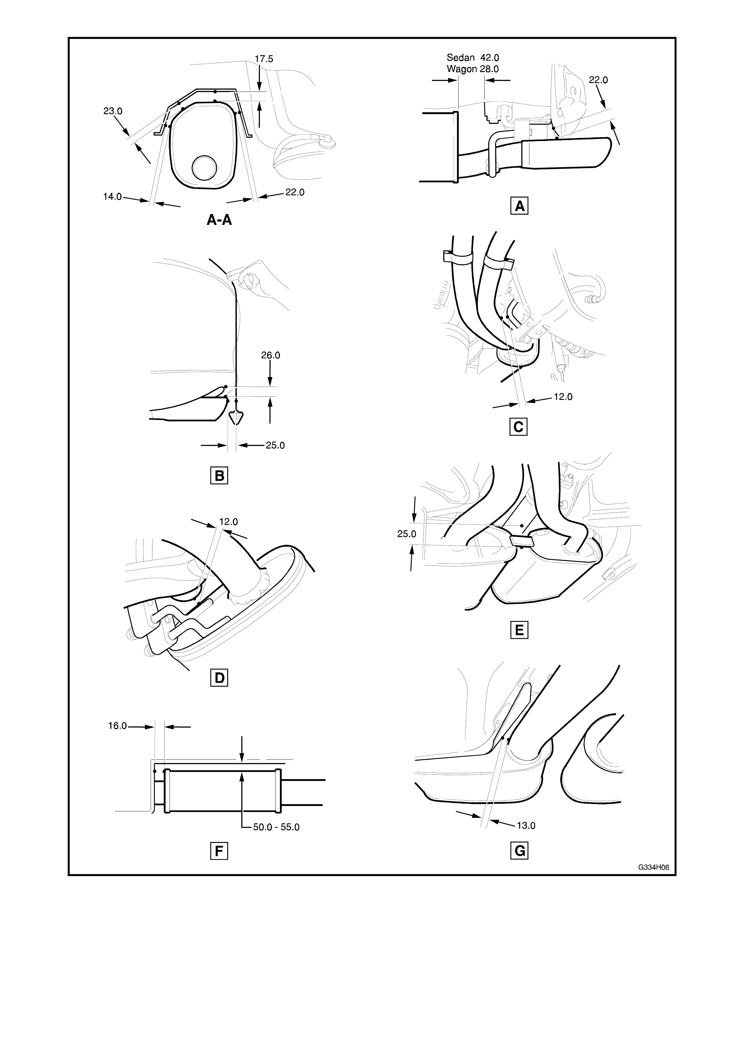
Figure 4H-6
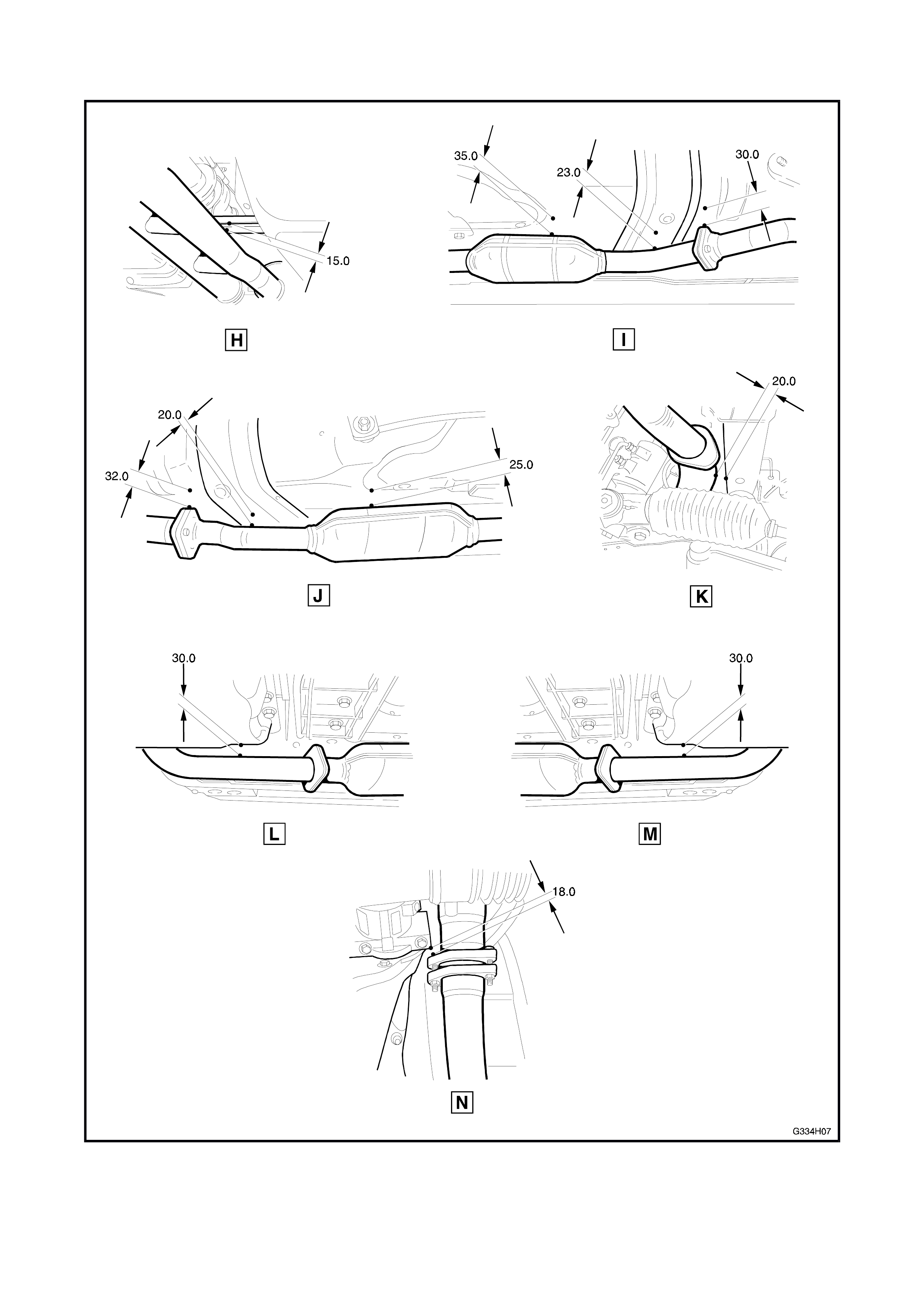
Figure 4H- 7
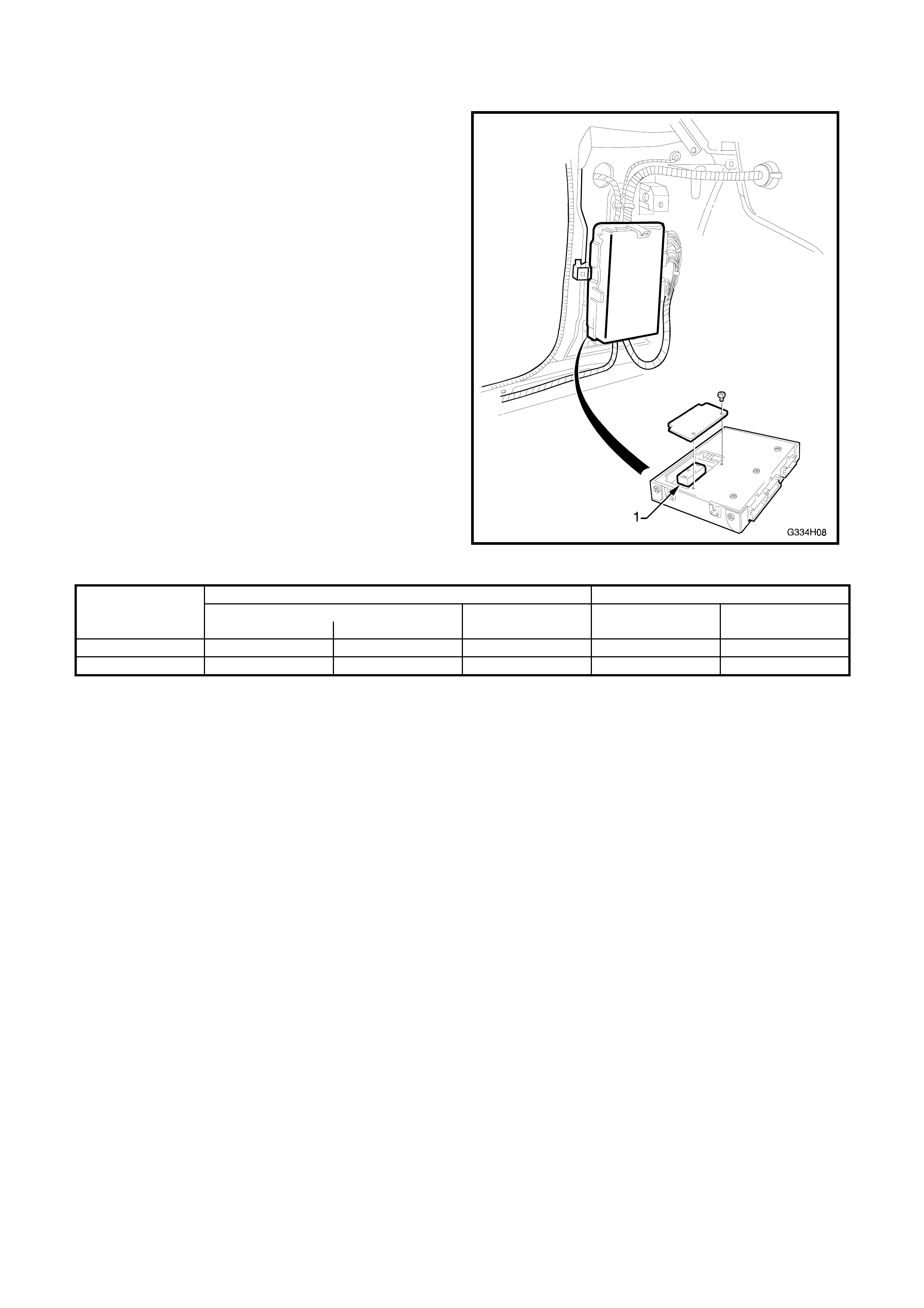
5. POWERTRAIN MANAGEM ENT
Changes to the powertrain management system for
the 195 kW V8 include the fitment of a revised
Powertrain Control Module PROM unit (1).
Service proc edures f or the Holden By Des ign 195 k W
V8 powertrain management system are the same as
the standard VT Series V8 powertrain management,
with the exception of the PCM & PRO M identif ic ations
as shown in the chart below.
Refer to Section 6C2, POWERTRAIN
MANAGEMENT - V8 ENGINE in the VT Series I
Service Information.
Figure 4H-8
PCM PROM
DELCO ID HSV SERVICE DELCO ID HSV SERVICE
P/N B/C P/N P/N PART NO.
195 Manual 16268298 CFZC 12F-970301 16268250 12F-970307
195 Automatic 16268288 CFZB 12F-970302 16268246 12F-970304

6. ‘V’ RATED TYRES
With the installation of the 195 kW V8 engine, VT
Executive and Berlina models are fitted with ‘V’ rated
tyres on the standard steel rims, unless alloy wheels
are optioned.
The standard tyre placard (1) is replaced to ref lect the
changes.
Figure 4H-9
The s pare wheel is not changed and is to be us ed as
a temporary w heel only.
Figure 4H-10
Service procedures for the wheels and tyres are the
same as the standard VT Series vehicles. Refer to
Section 10, WHEELS & TYRES in the VT Series I
Service Information.
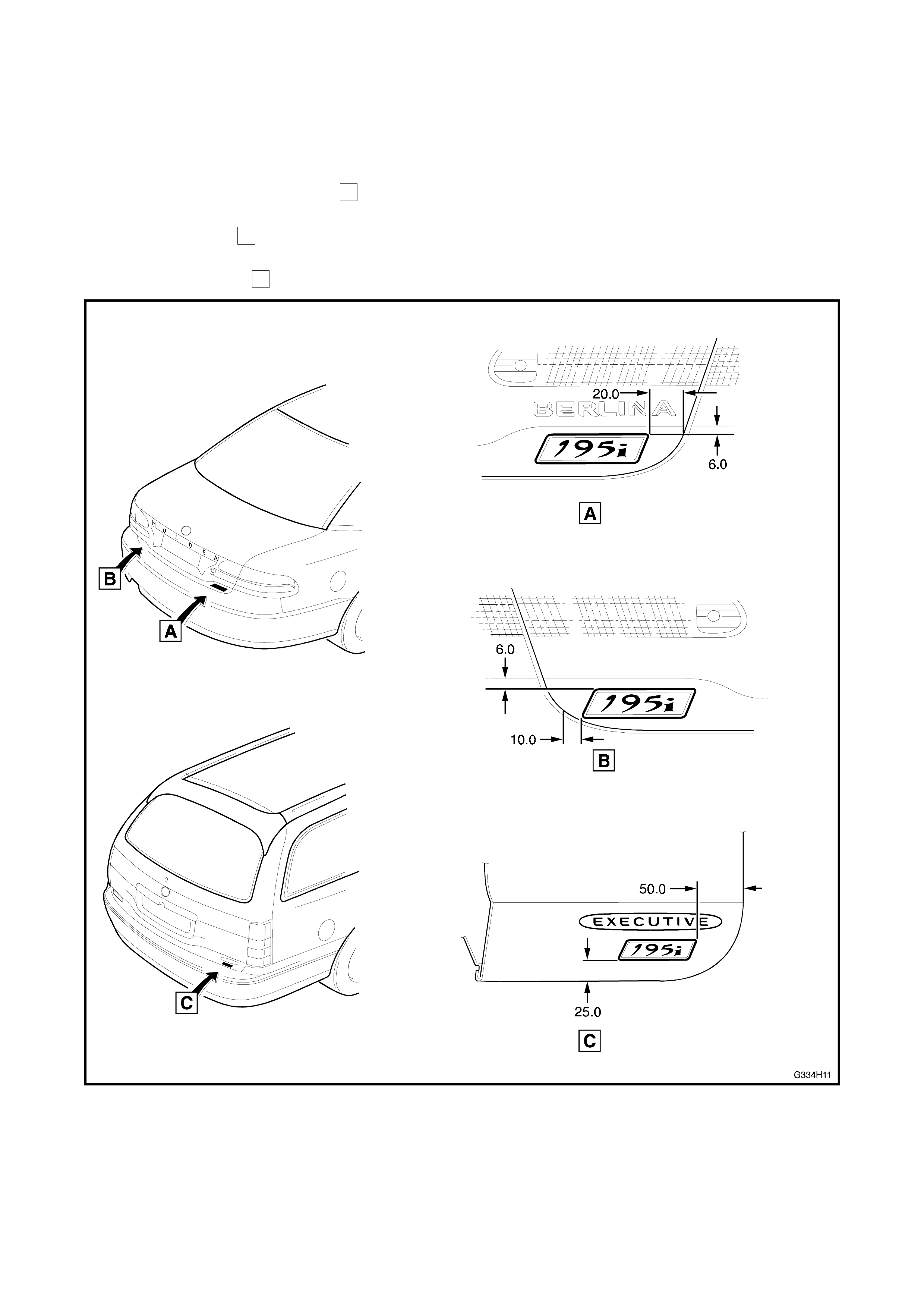
7. IDENTI FICATION & BADGING
Vehicles fitted with the 195 kW V8 engine, receive a
unique 195i decal, which is placed in the positions
shown in Figure 4H-11.
All sedan m odels ex cept SS, have the dec al af fixed to
the RH side of the deck lid as shown
A
.
SS models have the decal affixed to the LH side of
the deck lid as shown
B
.
W agon models have the decal affixed to the RH side
of the tailgate as shown
C
.
Figure 4H-11
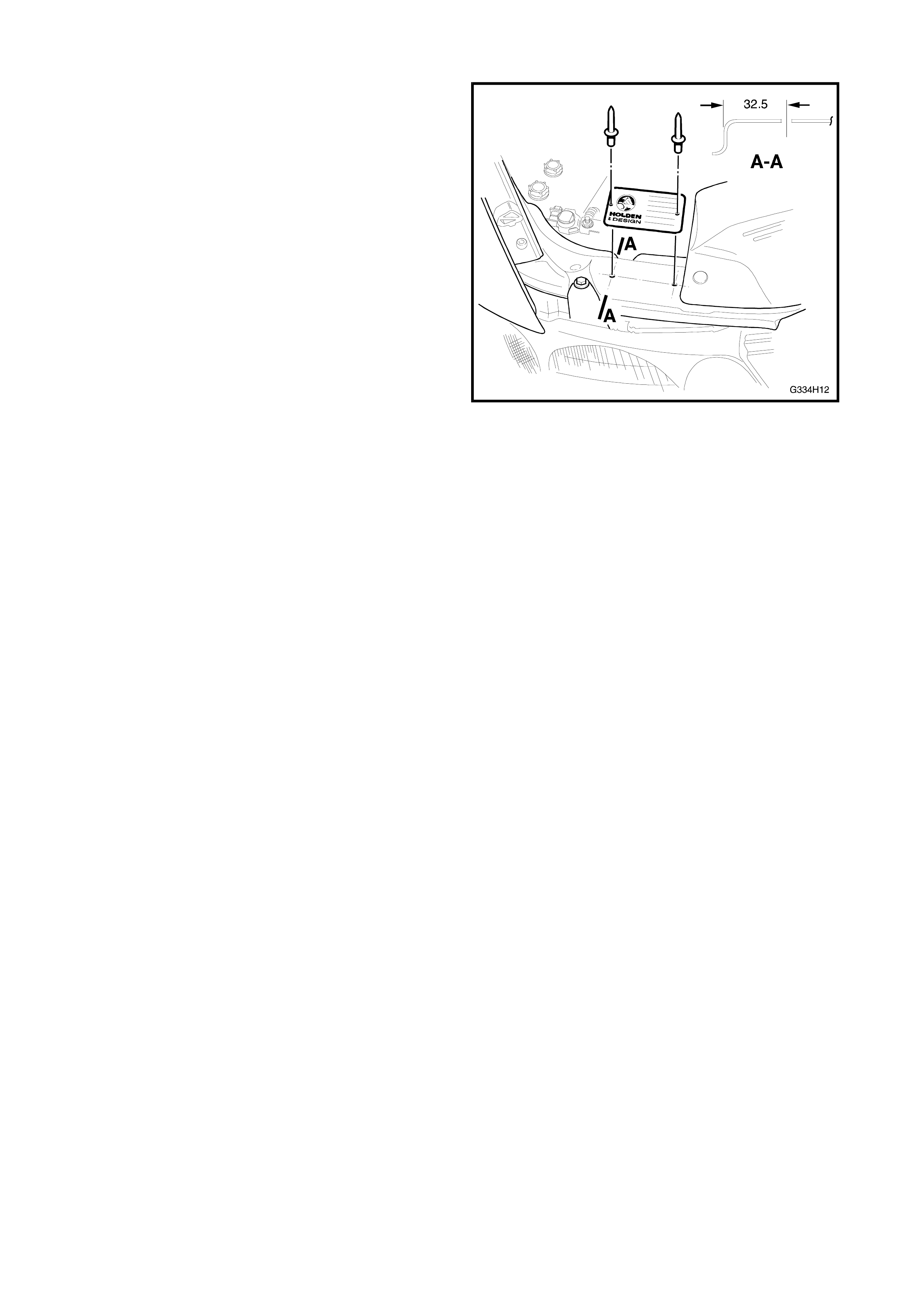
A HBD identification plate is also installed onto the
radiator support panel with pop-rivets.
Figure 4H-12