
SECTION C - SUSPENSION
CAUTION:
HSV vehicles are equipped with a Supplemental Restraint System (SRS). An SRS consists of seat belt
pre-tensio ners (fitted to all front seats), an d a driver’s-si de air bag AND a passenge r’s-side air b ag and
left and right hand side air bags. Refer to CAUTIONS, Section 12M, of the Holden VS Series Service
Information or Section 12M, of the VT Series II Service Information before performing any service
operation on or around SRS components, the steering mechanism or wiring. Failure to follow the
CAUTIONS could result in personal injury or unnecessary SRS system repairs.
PURPOSE
The purpose of this sect io n is t o pro vi de inf or mation on the front and rear s uspension ass emblies f itte d to HS V VT 2
and HSV m odels. T he infor mation is designe d to supp lement the inform ation cont ained in the Holde n VT Ser ies II
and VS Series Service Information, and details are given where differences occur between the HSV models and
standard Holden models. A series of instruction drawings describe the design changes and indicate specific part
numbers, fitting instructions and relevant notes for vehicle servicing.
NOTE:
If specific technical data on a HSV model is not contained in this supplement, obtain data for that model from the
relevant Holden VT Series II, W H or VS s eries Ser vice Inf ormation S upplem ent. Referenc es are m ade throu ghout
this section to Holden Service Information, to assist in providing information for specific service operations.
CAUTION:
W hen hoisting (or jack ing) HSV models, ens ure that t he lifting h ead of the hois t lifts on the chassis bef ore the arm
of the hoist contacts the side-skirt

FRONT SUSPENSION
1. GENERAL
The front suspension assembly fitted to all HSV VT2 and HSV VS models is based on the Holden ‘MacPherson
Strut’ design. All HSV front suspension struts are gas pressurised and Luxury and Grange struts have Monroe
Sensatr ac. This basic assem bly (and t he rear as sem bly) is then m odified by HSV to provide a suspens ion s ystem
more suited to the requirements of the owner and the HSV vehicle. That is, Performance and Sport suspension
systems are fitted to sport and performance type vehicles, and Luxury suspension systems satisfy the requirements
of the luxury sedans. A summary of these suspension systems and their Standard (S) and Optional (O)
applications is contained in the following paragraphs:
TABLE-1 - HSV SUSPENSION SYSTEMS
MODEL: SPORT PERFORMANCE LUXURY WH GRANGE
XU8 S
Senator Sed an O S
Senator Estate O S
SV99 S
ClubSport S O
XU6 S O
Grange S
Maloo S
ClubSport R8 S
GTS S

2. FRONT SUSPENSION COMPONENTS
The following components are fitted to front suspension assemblies as indicated:
Sport Suspension
03C-990601 Spring - Frt Susp (Sports)
03F-990601/2 Strut Asm - Frt - RH/LH
03G-970701 Bar - Front Stabiliser
Luxury Suspension
03C-990601 Spring - Frt Susp(Luxury)
03F-991601/2 Strut Asm - Frt Susp - RH/LH (Luxury)
03G-970701 Bar Front Stabiliser
Performance Suspension
03C-970701 Spring Frt Susp (Perform)
03F-990701/2 Strut Asm Frt RH/LH (Perform)
03G-970701 Bar Front Stabiliser
WH Grange Suspension
03C-970301 Spring - Front Suspension
03F-991301 /2 Strut Asm Frt-RH/LH
03G-970701 Bar - Front Stabiliser

3. SERVICE OPERATIONS
Service front suspension assemblies fitted to HSV models in accordance with the relevant Holden VT Series II or
VS Series Service Information. Additional service requirements for specific HSV suspension assemblies are
detailed in succeeding paragraphs.
CAUTION: SAFETY AND CAUTIONARY NOTE FOR VEHICLES EQUIPPED WITH ABS
Whenever any component that forms a part of the ABS is disturbed, it is vital that the complete ABS system is
check ed. Refer to Section 12L - ABS & ETC of the VT Series I Ser vice Inf ormation or the relevant section of the
VS Holden Service Information for details.
The tyre life of high performance low-profile tyres fitted to HSV VT2 and HSV VS vehicles is very sensitive to the
toe-in setting of the front suspension. It is crucial therefore, that care is taken to set the toe-in accurately to the
correct specification.
The front wheel alignment specification for HSV VT2 & WH and HSV VS vehicles is:
VT2 & WH VS
Toe-in Degrees Total 0°10' ± 0°10' 0°40' ± 0°10'
Degrees Per Wheel 0°05' ± 0°5' 0°20' ± 0°05'
Camber -0°30' ± 0°20' -0°25' ± 0°05'
Caster 7°45' ± 1°15' 4°45' ± 1°15
• The toe-in specification is deliberately quoted as an angle because wherever possible toe-in should be
measured in degrees.
• If toe-in is to be measured in millimetres refer to Holden Service Bulletins April 1992 and November
1993 to ensure accurate results (VT, 1mm ± 1mm; VS 4mm ± 1mm). A summary of the November 93
Bulletin follows.
WHEEL ALIGNMENT MACHINE CALIBRATION
(From Holden Service Bulletin November 1993)
Investigation of front wheel alignment complaints has revealed a number of dealers with alignment machines
incorrectly calibrated for the vehicle/s being checked. This situation arises because of two basic conventions for
measuring toe-in;
• Measured across a 14"rim as if tyre is not fitted, and
• Measured across 28" tyre. In reality, few modern tyres have a 28"outside diameter, but this standard
was developed when larger tyres were used.
The 28"standard is a carry over from the days when toe-in was measured by jacking the front wheels off the ground,
spinning them , and scrib in g a referenc e li ne on eac h tre ad. After settlin g th e veh ic le do wn, th e to e-in could t hen be
measured directly from the tyres with a ‘trammel bar’. However, some manufacturers specify toe-in as if the
tramm el bar was placed at the wheel r im diam eter, nom inall y 14" S etting t oe-in usin g the wrong co nvent ion f or the
wheel alignment machine will cause the actual toe-in to be either TWICE or HALF as much as the specification.
NOTE: IF IN DOUBT, SET TOE-IN USING DEGREES, AS THE ANGLE IS UNAFFECTED BY THE DIAMETER
OF THE WHEELS USED.
Techline

HOW TO CHECK YOUR MACHINE
Check with the m anufac turer of your equi pm ent if uns ure of whic h stan dard your m achine us es to displa y toe-in. If
unable to establish this, or if your machine appears to be inaccurate, check the machine as follows:
• Fit properly inflated 15"wheels and tyres to the front of a VP or VR Commodore. Jack the car, spin the
wheels and scr ibe a line at t he middle of eac h t yre S et the veh icle on the al ignment m ac hine a nd set toe-
in to 10mm (5mm per wheel).
• Measure toe-in at r ear of t yres and th en at fr ont of tyres with a ‘tramm el bar ’. If the f ront distance is less
than the rear distance, you are measuring the toe-in correctly. Compare the measured toe-in to the
following table to assess your machines calibration.
MEASURED TOE-IN RESULT
7 to 11 mm Machine reads @28"
16 to 22 mm Machine reads @ 14"
OTHER CALIBRA TE MACHINE
NOTE: The above figures are correct for a 205/65/15 tyre, being a 25"diameter.

4. SERVICE INTERVALS
HSV front suspension assemblies are to be serviced at the intervals directed in:
Section 0B - Lubrication And Service of the VT Series II Service Information or
Section 0B - Lubrication And Service of the WH Statesman and Caprice Service Information or
Section 0B - Lubrication And Service of the VS Series Service Information.

INDEPENDENT REAR SUSPENSION
1. GENERAL
Rear suspension assemblies fitted to HSV models are detailed in the matrix in Front Suspension, paragraph 1:
these ass emblies hav e b een de veloped to s at is fy the various a pp lic at io ns of the r an ge of HSV models des c ribed in
that paragraph. Non level ride shock absorbers are gas pressurised, level ride are not.

2. REAR SUSPENSION COMPONENTS
The following components are fitted to rear suspension assemblies as indicated:
Sport Suspension
04B-970702 Spring - RR Susp (Sport)
04E-990601 Shock Abs - RR (Sport)
04F-971001 Bar - RR Stabiliser (Sport)
Luxury Suspension
04B-970801 Spring - RR Susp (Sedan)
04B-970201 Spring RR Susp (Estate)
04E-991601 Shock Abs - RR (Luxury Sedan) Sensatrac
04E-991801 Shock ABS-RR (Estate) Sensatrac
04F-971001 Bar RR Stabiliser
Performance Suspension
04B-970702 Spring RR Susp (Sport )
04E-990703 Shock ABS-RR (Perform)
04F-970301 Bar-RR Stabil is er( Perform )
04E-990704 Shock ABS RR (Perform, Lvl ride, sedan)
04E-971003 Shock ABS RR (Perform, Lvl ride, wagon)
04E-971004 Shock ABS RR (Perform, non Lvl ride, wagon)
04A-990603 Rear bush, Performance suspension *
WH Grange Suspension
04B-991301 Spring Rear Suspension
04E-991301 Shock Absorber - Rear Suspension
(Lvl ride, Sensatrac)
04F-970301 Bar - Rear Stabiliser
*VT2 Performance suspension has a firmer suspension bush fitted to the inboard side of each of the rear
semi trailing arms.

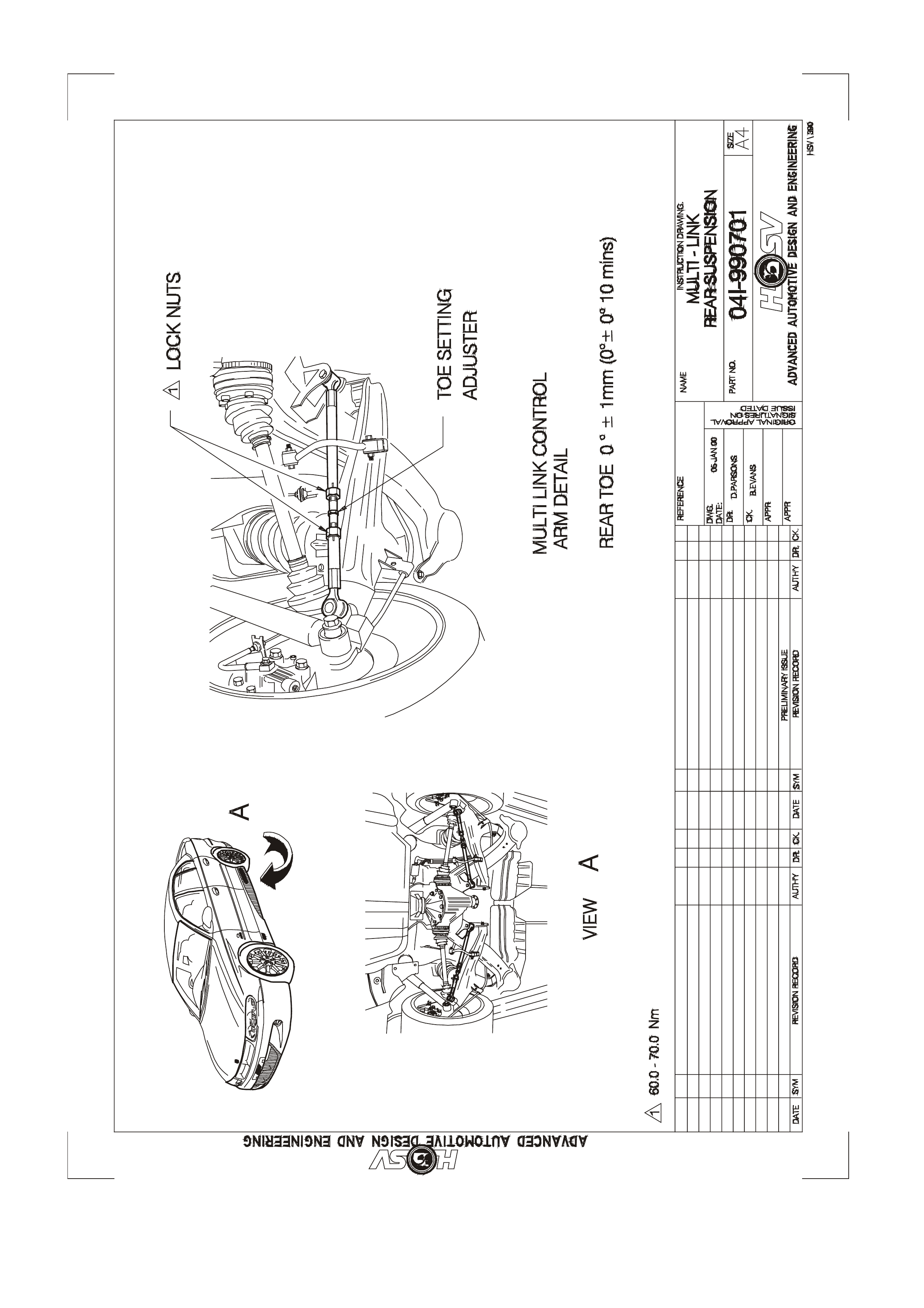
SERVICE INFORMATION FOR MULTI LINK IRS
Fitted to the VT2 GTS IRS is the Multi Link Suspension System. The major components of the Multi Link system
include the following :
Cross Member Asm-Rr-Multi Link 04A-990710
Control Arm-Multi Link 04A-990701
Bush-Multi Link 04A-990706
The multi link cross member is unique to the standard cross member in that it has four brackets welded onto it to
support the front of the control arm. Each multi link rear semi trailing has the multi link bush pushed into the inboard
side which is voided to allow for side movement and also a tapered hole drilled at the lower part of the arm for
mounting of the rear of the control arm . The control arm links connect from the sem i trailing arm to the r ear cross
mem ber, these link s give sup port to th e sem i trailing arm and reduc e suspens ion t oe chang e dur ing c ornering a nd
increased vehic le load. T he mu lti link c ontrol arm is also adj ustable in lengt h and alter s the r ear t oe. It is im portant
that vehicl es fitted with Multi Link are wheel align ed using a four whee l aligner, t his ensures that the fr ont and rear
geometry’s are tracking in line.
Refer bel o w for the rec omm ended whee l a lignment settings . These sett ings are at curb weig ht, whic h is the v ehicle
in a condition of full fluids, full fuel, no people or luggage.
Rear Toe : 0 ± 1mm (0°± 0°10mins)
Camber : -1°30mins to -2°30mins
Torque Settings : 65 ± 5Nm
Refer to the following Figure: 041-990701

2.1 REAR SUSPENSION - LUXURY - (INCORPORATING AUTOMATIC LEVEL RIDE)
2.1.1 GENERAL DESCRIPTION
Automatic Level Ride is fitted as standard to Senator, Senator Signature Estate, Grange and is optional on other
models. Automatic Level Ride is an electronically controlled self levelling system that maintains the vehicle at a
constant tr im height, independent of load. T his feature us es a specif ically des igned e lectronic sensor, f ixed to the
rear cr ossmember on the rig ht han d s i de (s ee Figure C-1) , which c o ntr ols an e lectr ic motor drivi ng a sing le cylinder
air compressor, and an exhaust air solenoid valve. The compressor supplies the necessary pressure to operate
the Air Shock Abs orbers v ia "snap o n" air lines. T he Air Shoc k Absor bers ass ist the rear s prings i n sup porting t he
vehicle body under all loads.
The sensor has an integrated electronic controller that is programmed to adjust ride height only when necessary,
ignoring sudden changes, as experienced on bumpy roads. The design of the system maintains trim at all times
provided the battery is connected. As a safeguard to prevent the battery being flattened, an electronic timer
switches off the compressor if it runs for a prolonged period (i.e. due to an air leak in the system).
The compressor assembly includes a maximum pressure release valve and an air drier. All air entering or
exhausting t he system flows through the dryer, which has an intern al minim um pr essure retent ion val ve prevent ing
the Air Bag, surrounding each Shock Absorber, from completely exhausting independent of the sensor controlled
exhaust va lv e.
A number of benefits result from the level ride feature. These include headlamp aim and rear view mirror
adjustment being mainta ined independent of load, as well as ensur i ng t he rear wheel c amber and to e-in are held at
the optimum positions to minimise tyre wear. An additional major benefit is obtained from supplementary design
changes that can be made to spring and damper rates for improved ride quality at all loading conditions with
minimum compromise to handling. These changes are possible since the suspension does not have to be
sufficiently stiff to absorb road impacts, while supporting maximum vehicle load.
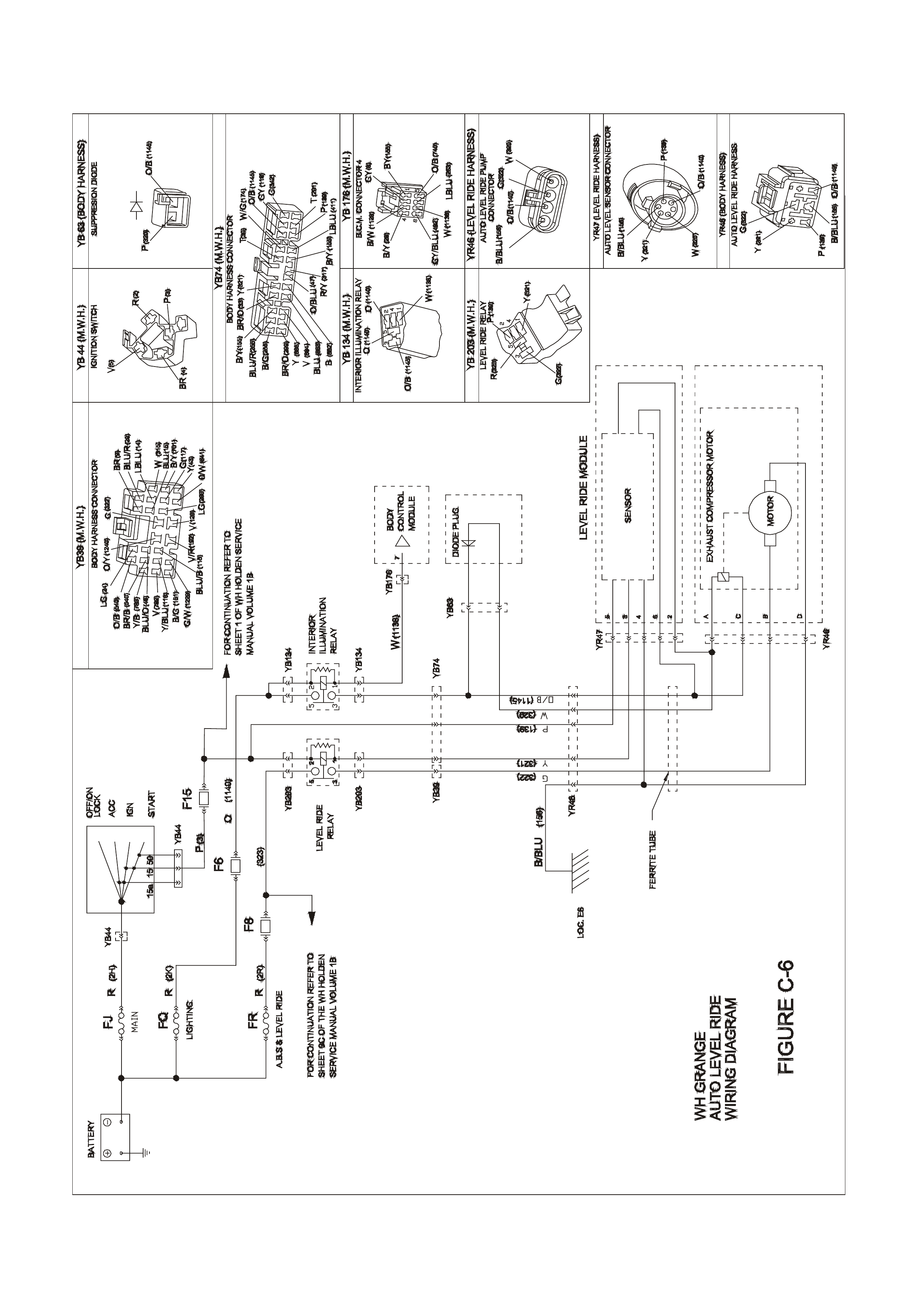
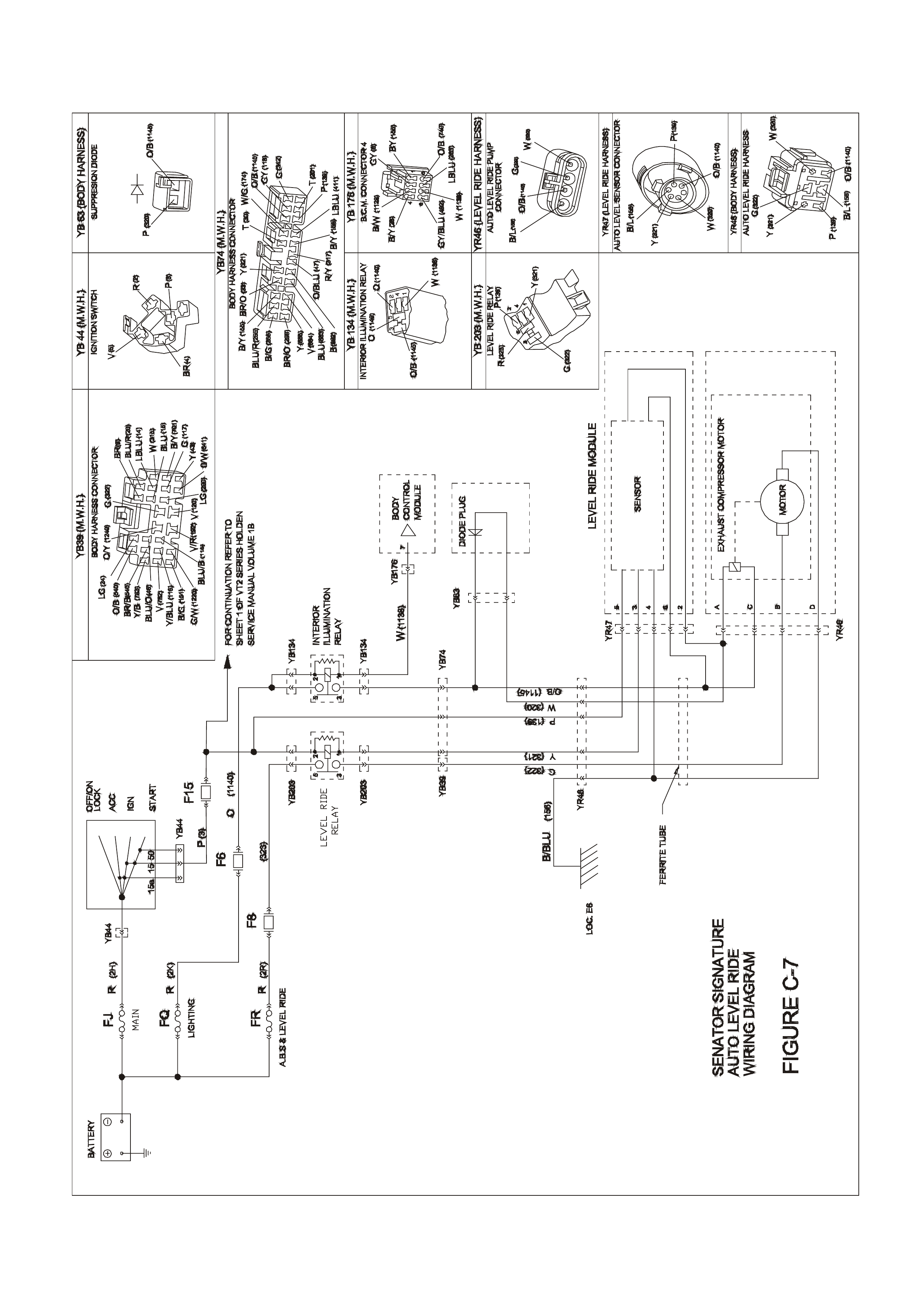
Electr ical power to operat e the Lev el Ride s ystem is supplie d by a separ ate h arness except the Senator Signatur e
model which uses the main integrated wiring harness and a short ‘patch harness.’
2.1.2 SYSTEM OPERATION
Activation
The s ensor 's actuati ng ar m is attache d to the lo wer control arm via a connec ti ng li nk (See Figure C-1). Before an y
activation can occur the actuating arm must remain in either the intake or exhaust zone for a continuous 17 to 20
seconds.
The time delay prevents the compressor or exhaust valve from activating when the vehicle encounters sudden
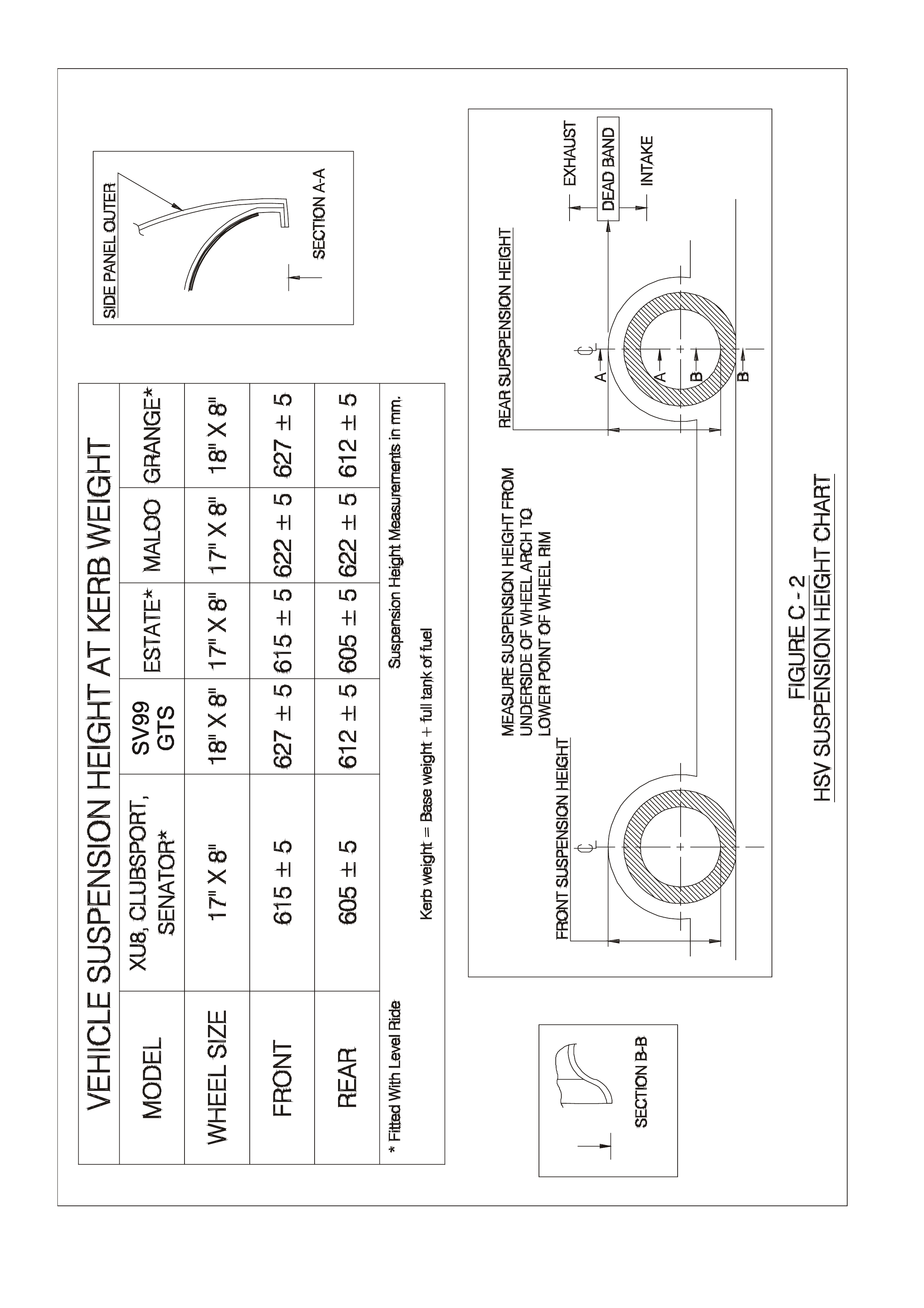
bumps. Another stability feature is a designed "Deadband". The Deadband helps to minimise hunting by
deactivating the compressor and solenoid when the vehicle trims into or onto one of the Deadband edges. Refer to
Figure C-2 for details on rear suspension trim heights and Deadband.
Loaded Vehicle
When the vehicle is loaded, the vehicle body moves downward into the intake zone, causing the actuating arm to
move upwards. After 17 to 20 seconds, the sensor relieves compressor head pressure by briefly activating the
compressor relay. The compressor starts and pressurises the air shock absorbers until the vehicle body aligns with
the bottom edge of the Deadband, at which point the compressor stops.
Unloaded Vehicle
W hen the vehicle is unloaded, the veh icle bod y moves upward into the exhaus t zone, ca using the actuating ar m to
move do wnwards . Af ter 17 to 20 sec onds, t he se nsor ac tivat es the ex haus t re lay. T he exhaus t s oleno id ac tiva tes
and vents press ur e from the air shock absorbers until the ve hic l e bo dy aligns with th e to p edge of the Dea d band, at
which point the solenoid deactivates.
Deactivation
The compressor and exhaust solenoid operations are monitored and controlled by individual but interconnected
timers. The timers deactivate specific trimming operations under the following conditions:
a. If the compressor runs for a cumulative time of more than four-and-a-half minutes, the compressor timer
deactivates all system operations.
b. If the exhaust solenoid is active for a cumulative time of more than four-and-a-half minutes, the solenoid
timer deactivates the solenoid.
NOTE: The sensor timers must be reset before any further operation can take place. The VT2 system is
reset after each ignition cycle ON, OFF for one minute, ON.

2.1.3 MAINTENANCE
Service
CAUTION: DO NOT LOWER CAR WITH EMPTY SHOCK ABSORBER AIR BAGS AS DAMAGE MAY RESULT.
This system is designed to run with the minimum of maintenance. At every service the following components
should be checked:
a. Air Lines: Inspect lines and replace if sleeving or line is worn. Refer Section, Air Line for service
instructions.
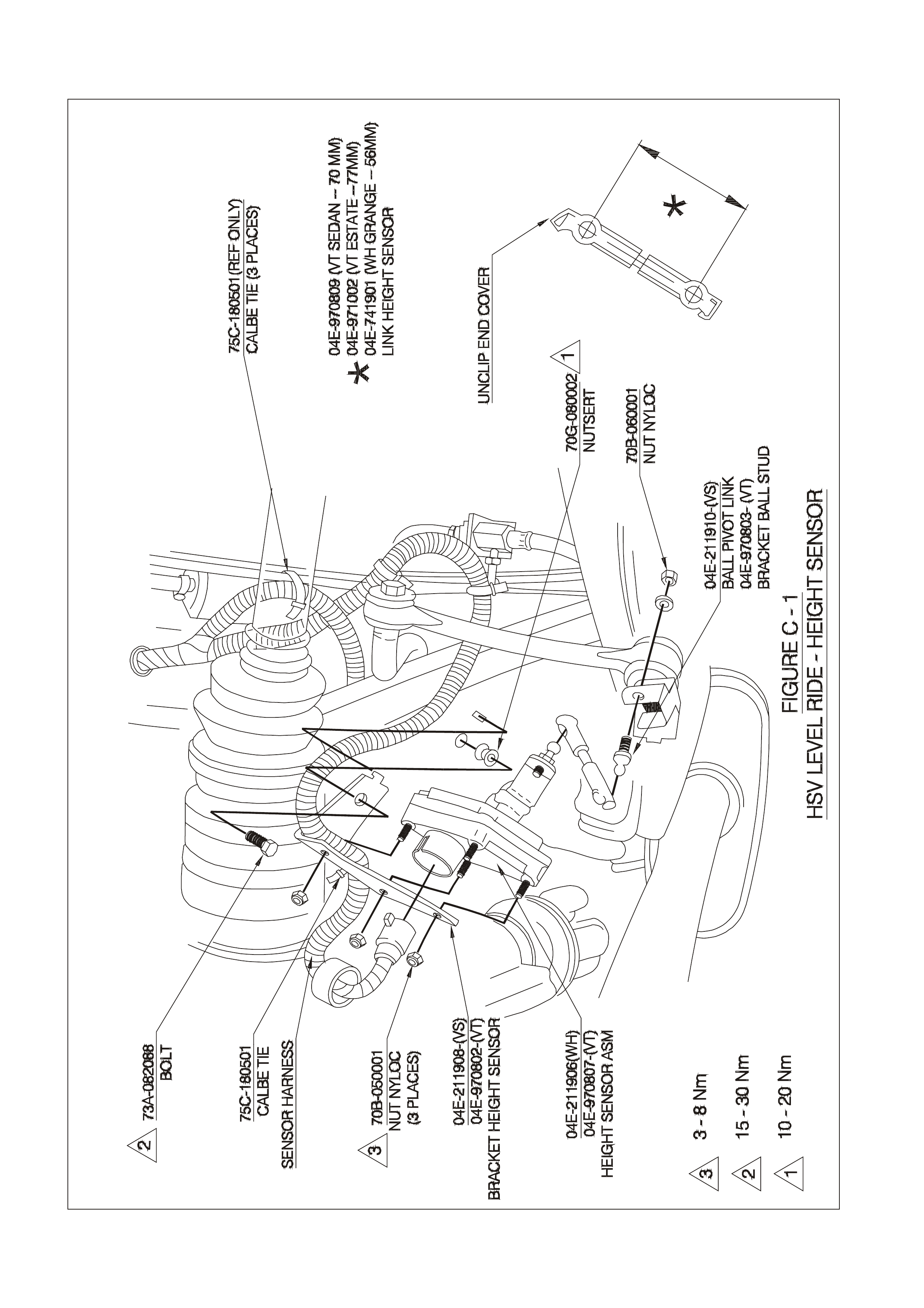
b. Harness Ties: Check harness ties and replace if broken or loose, refer Figure C-1 and Figure C-3.
c. Compressor Mounts: Check co mpressor mounts and replace if broken. Check security of mounts.
d. Air Filter: Inspect and replace air filter if contaminated or at the 30,000km, 70,000km and subsequent
40,000km service intervals, whichever comes first. Follow instructions in Section, Air Filter - Removal for
replacement details.
NOTE: The Air Filter is the only regular service item.
Contents of Automatic Level Ride System
VT2 Level Ride System
PART NO DESCRIP TI ON
04E-970807 HEIGHT SENSOR-ASM
04E-970802 BRACKET HEIGHT SENSOR
70B-050001 NUT NYLOC
73A-082088 BOLT (HT SNSR BRKT TO XMBR)
70G-080002 NUTSERT
04E-970803 BRACKET BALL STUD
04E-970809 LINK HEIGHT SENSOR SED, LUX 70mm
04E-971002 LINK HEIGHT SENSOR WAG, LUX 77mm
04E-211917 COMPRESSOR
04E-970805 BRACKET COMP TO BODY
73A-053088 BOLT (COMPRESSOR TO BRKT)
72H-970801 BOLT (COMP BRKT TO BODY)
04E-211913 T PIECE
04E-211914 AIR FILTER
75C-180501 CABLE TIE
04E-970806 AIRLINE ASM-COMP TO SHOCK ABSORBER
12H2970801 LEVEL RIDE PATCH HARNESS
12H2970803 LEVEL RIDE UNDERBODY
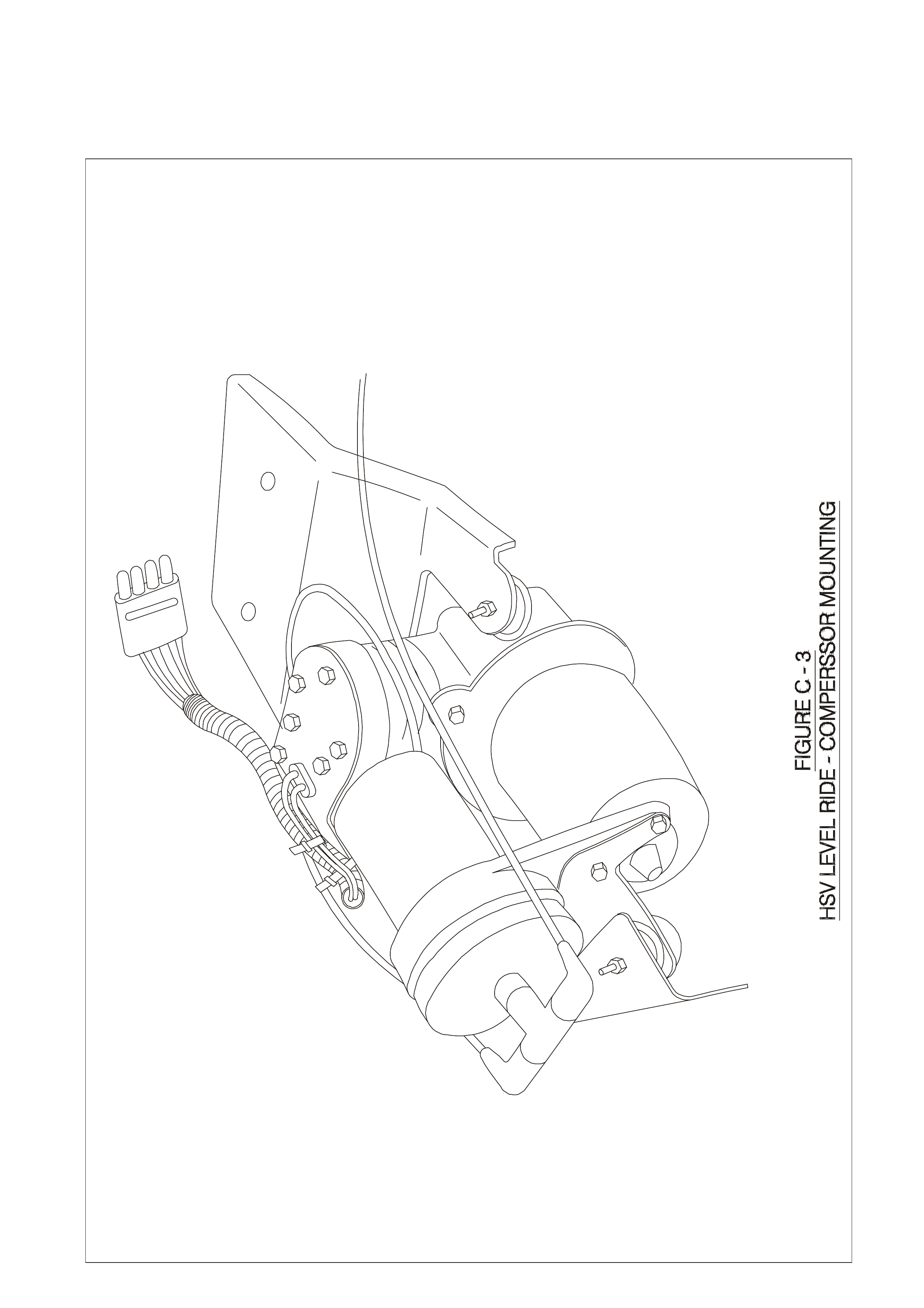
2.1 .4 COMPRE SSOR ASSEMBLY - SERVICE
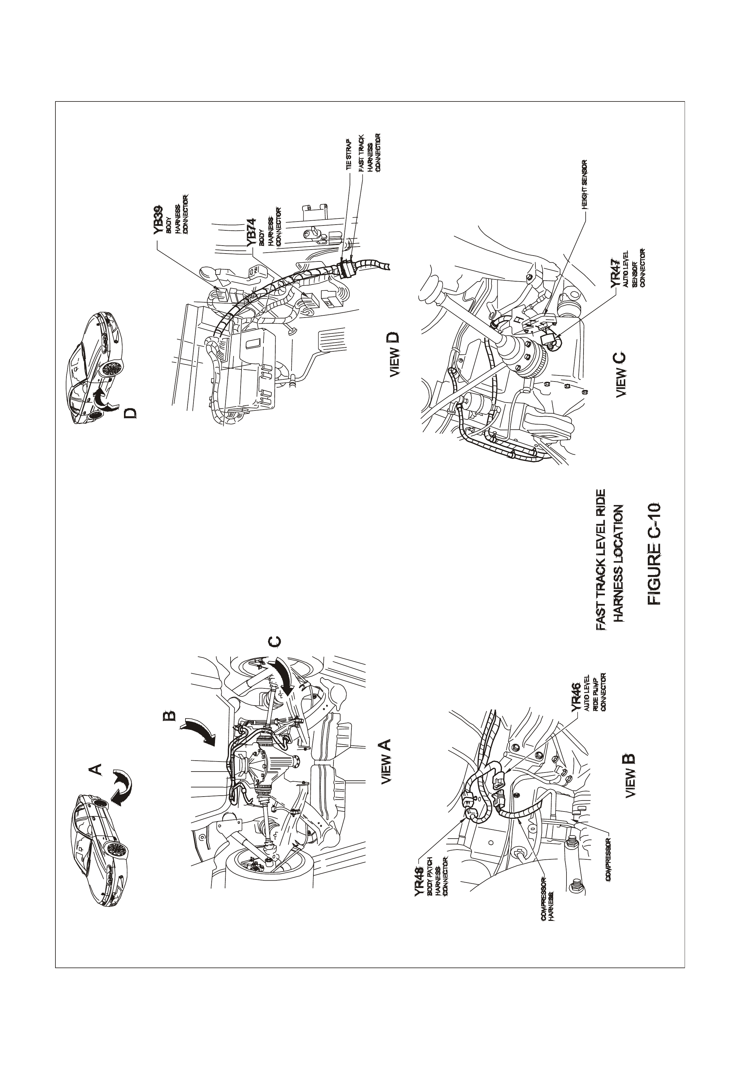
The com pressor assembl y is located ab ove the lef t hand rear ax le shaft and bel ow the floor pan. The VT 2 system
is secured to a com pressor br acket which t hen m ounts to the c hassis subf ram e. The general arrangem ent f or VT2
Compressor Assembly is shown in Figure C-3.
Removal
Remove the air filter, remove the three screws securing the compressor to the compressor mounting bracket and
remove compressor assembly.

2.1.5 AIR LINE AND AIR FILTER - SERVICE
AIR LINE
Removal
Disconnect snap-on air lines by rotating each clip 90° and gently pulling the line free. Cut or unclip air lin e ties .
Installation
Reverse the above procedure taking care not to kink lines when installing to shock absorber. Ensure air lines do
not contact sheetmetal raw edges.
NOTE: ENSURE THAT AIR LINE TIES ARE CORRECTLY POSITIONED AND THAT AIR LINES ARE SECURE.
AIR FILTER
Removal
Remove compressor assembly as per instructions, refer Section 2.1.4 Compressor Assembly Service. Unclip
filter from compressor isolation bracket and twist free from air hose.
Installation
Secure new filter to bracket and connect hose. Refer Figure C-3 for correct filter location.
2.1.6 SHOCK ABSORBER - SERVICE
The shock absorbers are serv iced as per the sta ndard Holde n rear sh ock absorbers. Ref er to the rel evant Ho lden
Service Information.
CAUTION: DO NOT LOWER CAR WITH EMPTY AIR BAGS AS DAMAGE MAY RESULT. WHENEVER THE
SYSTEM IS UNPRESSURISED OR WHEN THE VEHICLE REAR SITS OBVIOUSLY HIGH AFTER LOWERING
FROM AN ON-HOIST OPERATION (SUGGESTING SHOCK ABSORBER AIR BAGS MAY BE PINCHED OR
JAMMED), IMMEDIATELY RAISE VEHICLE, DISCONNECT SENSOR CONNECTING LINK, PUSH SENSOR
ARM ABOVE HORIZONTAL FOR 17 TO 20 SECONDS, AND RUN COMPRESSOR FOR ABOUT 30 SECONDS
TO INFLATE SHOCK ABSORBERS. RECONNECT SENSOR CONNECTING LINK AND LOWER VEHICLE.
DRIVING THE VEHICLE WITH PINCHED OR JAMMED SHOCK ABSORBER AIR BAGS WILL IRREPAIRABLY
DAMAGE THE SHOCK ABSORBER
2.1.7 HEIGHT SENSOR - SERVICE
The heig ht sensor as sembly is bo lted to the rear crossm ember on the r ight hand side as illustrate d in Figure C-1.
The sensor bracket specification is critical and essential that the bracket is not bent or distorted. Read the
installation procedure carefully before fixing the bracket to the crossmember.
Removal
a. Unclip or cut cable ties as appropriate which supp ort sensor harness to the height sensor brack et. Separate
the harness from the sensor gently squeezing and pulling away the connector retainer. Refer Figure C-1.
b. Remo ve height sensor link by uncl ipping link end co ver and gen tly pr ying from sensor arm . Refer Figure C-1
for link details.
c. Support sensor while removing sensor bracket bolt (73A-082088). Refer Figure C-1.
Installation
Before proceeding any further, check that the sensor bracket is within specification as detailed in
Section 2.1.10 Level Ride Specifications. Reverse the above procedure, taking care not to bend or distort the
bracket. Ensure link clip is refastened otherwise, system failure may occur.
2.1.8 RELAY CONTROL MODULE - SERVICE
VT2 relays are incorporated in the Relay Box in the driver’s-side lower dash panel.

2.1.9 DIAGNOSTICS
General
The following procedures are guides that can help to determine the probable cause of an Automatic Levelling
System problem.
It is important that the reader is familiar with Section 2.1.2 System Operation, in order to accurately identify the
problem.
Test Equipment Required
1. DC Voltmeter and Ohmmeter(>20 megohm/ v).
2. Jumper leads required for short circuit (cct.) tests.
2.1.10 LEVEL RIDE SPECIFICATIONS
The rear suspension height specifications are shown on Figure C-2.
To achieve this specification note the following:
1. The vehicle must be at kerb weight, see Figure C-2.
2. The internal angle of the Height Sensor Bracket is 80 degrees.
2.2 REAR SUSPENSION - MALOO 195I UTILITY
The load carrying capacity of the Maloo has been increased by the addition of HSV modifications to the rear
suspens io n of the ve hicle. The act ual payload spec if ic at ion is l imited by the tyre load c ap ac ity and the need to l imit
the maximum rear axle load to 1120 kg. A spacer is also f itted to the right hand r ear suspension t o c ompensate for
the weight of the fuel tank (and fuel) which is located to the right hand side of the vehicle. Components used to
modify the rear suspension are as follows:
04B-208001 SPRING - REAR SUSPENSION
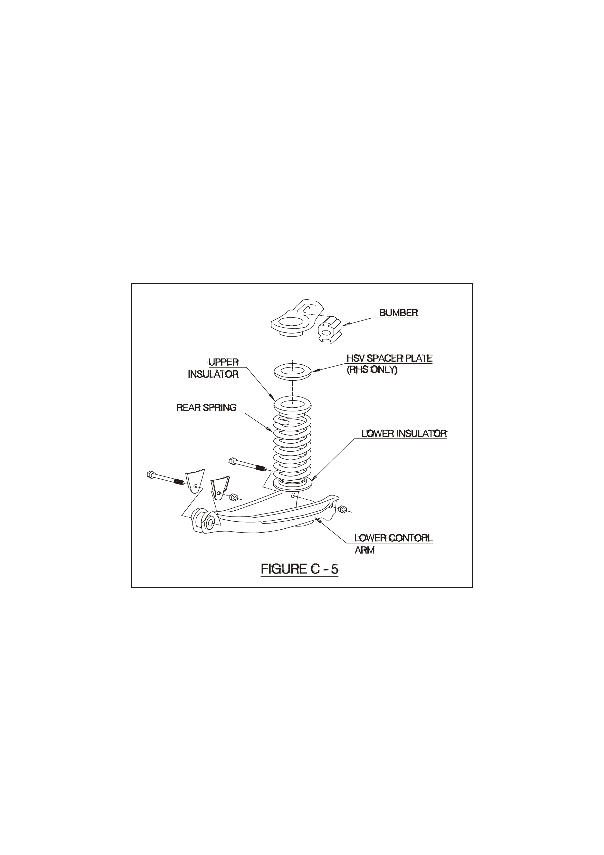
04B-208003 SPACER - SPRING SEAT - RH
04E-970501 SHOCK ABSORBER
04D-208001 ROD ASM - PANHARD
05E-738001 ADAPTOR - RR BIAS VALVE
70A-060001 NUT - HEX (M6)
70B-060001 NUT - NYLOCK (M6)
NOTE: To ensure correct ride height and ride quality, the spacer plate must be fitted to the right hand rear of the
vehicle as shown in Figure C-5.
REAR SUSPENSION UTILITY
2

3. SERVICE OPERATIONS
Service Operations and Service Intervals for HSV Rear Suspension assemblies are the same as those detailed
in the relevant of the VT Series II Service Information except when detailed otherwise in this supplement.
The Height Sensor Link part number and length for each Level Ride application is as follows:
04E-970809 (VT2 SEDAN and WH Grange - 70mm)
04E-971002 (VT2 ESTATE - 77mm)
For rear wheel alignment specif ication, refer to Section 4A REAR SUSPENSION – Early Production Tr ailing Arms
or Section 4A REAR SUSPENSION – Local Production Trailing Arms of the VT Series II Service Information or
Section 4A - Rear Suspension of the VS Series Service Information. For trim height specifications refer to
Figure C-2.
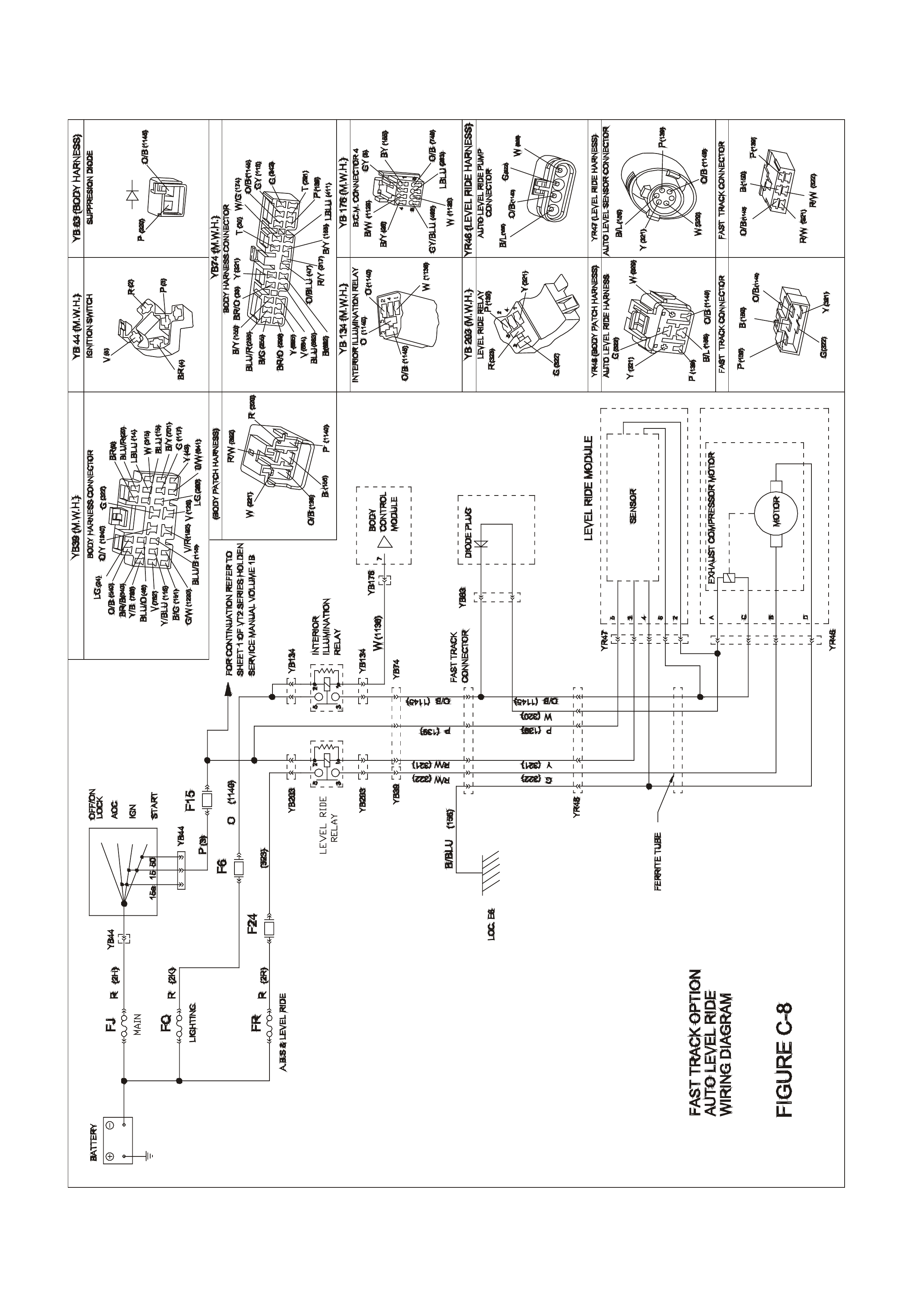
Wiring connections for the VT2 system are shown in Section 12N - Fuses, Relays And Wiring Harnesses or
Section 12P - Wiring Diagrams of the VT Series II Service Information.

4. DIAGNOSTICS
4.1 The following procedures are guides that can help determine the cause of problems with the level ride system.
It is important that the user of these procedures has a working knowledge of the level ride system.

4.2 PRELIMINARY DIAGNOSTIC PROCEDURE
Step Action Value Yes No
1. Does vehicle trim? Go to Step 2 Go to Step 3
2. Does vehicle trim to correct height? Refer to
Figure C-2
SPECIFCATIONS
System OK Check all rear
suspension
components for
wear and
damage, paying
particular attention
to the height
sensor mounting
and bracket
3. Does vehicle lower after specified time when vehicle is
unloaded? 20 seconds Go to Step 4 Go to Chart, 4.3
COMPRESSOR
ASM TEST
(SOLENOID
TEST)
4. Does vehicle rise after specified time when vehicle is
loaded? 20 seconds System OK Go to chart 4.4
COMPRESSOR
ASM TEST
(MOTOR TEST)

4.3 COMPRESSOR ASSEMBLY TEST (SOLENOID TEST)
Step Action Value Yes No
1. • Has a system reset been carr ied out by cycli ng
ignition, refer 2.1.9 DIAGNOSTICS in this Section? Go to Step 2 Carry out
system reset
and re-check
system
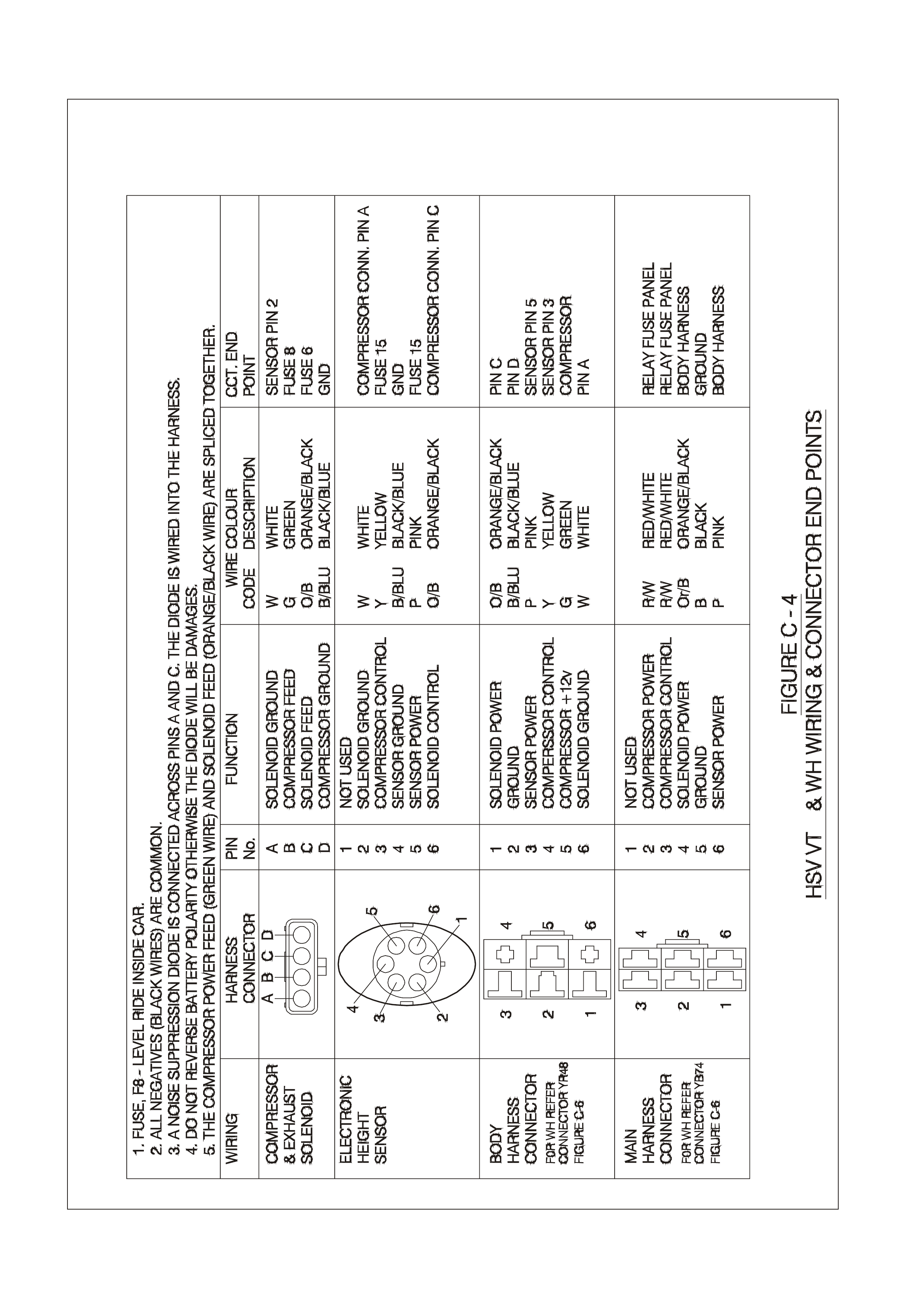
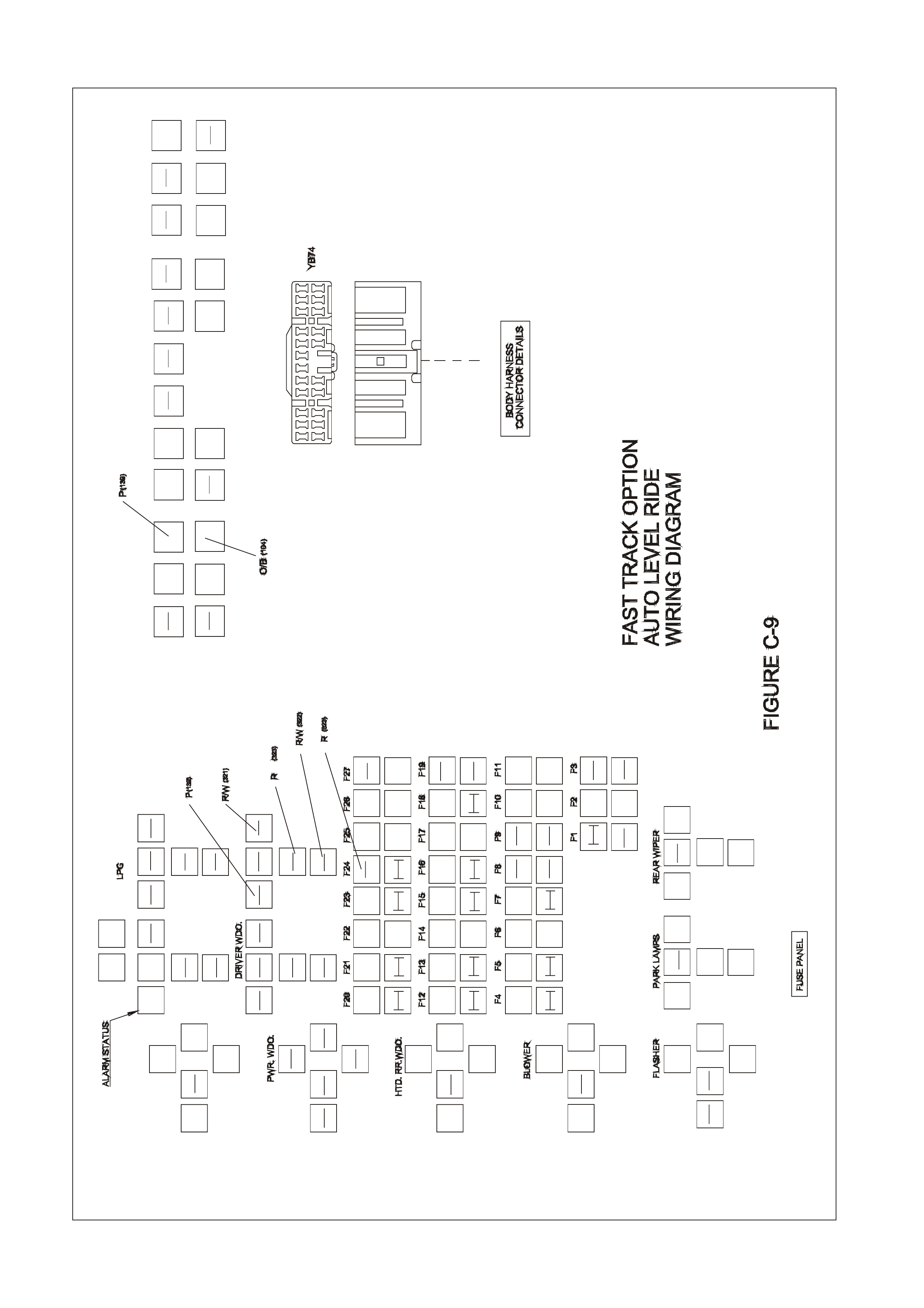
2. • Is fuse 8 OK (25 amp fuse .) ?
• Is fuse 6 OK ( 10 amp fuse in fuse panel) ?
• Is fuse 15 OK (10 amp fuse in fuse panel) ?
Go to Step 3 Replace blown
fuse/s, check
wiring for
cause of
fuse/s blowing
and re-check
system
3. • Disconnect the wiring harness at the level ride sensor
• Turn ignition ON
• Short circuit pin 2 (white wire) to pin 4 (Black wire) in
the level ride sensor connector (connector YR47)
• Listen for clicking of the solenoid valve and the air
escaping from the system, or check for voltage
between pin A & C at the compressor harness
connector (connector YR46).
• Is there a clicking sound from solenoid valve,
escaping air from the system or voltage at the
compressor harness connector between pi n A
(Orange/Black) wire & C (white wire)?
Compressor asm
solenoid OK,
proceed to Chart
4.5 HEIGHT
SENSOR TEST
(SOLENOID
OPERATION) in
this Section
Go to Step 4
4. • Check system wiring for continuity
• Is wi ring OK?
Replace
compressor
assembly refer
2.1.4
COMPRESSOR
ASSEMBLY -
Service
Test system
with other
harnesses-
replace as
necessary.

4.4 COMPRESSOR ASSEMBLY TEST (COMPRESSOR MOTOR TEST)
Step Action Value Yes No
1. • Has a system reset been carr ied out by cycli ng
ignition, refer 2.1.2 Deactivation Note in this Section? Go to Step 2 Carry out
system reset
and re-check
system
2. • Is fuse 8 OK (25 amp fuse.) ?
• Is fuse 6 OK ( 10 amp fuse in fuse panel) ?
• Is fuse 15 OK (10 amp fuse in fuse panel) ?
Go to Step 3 Replace blown
fuse/s, check
wiring for
cause of
fuse/s blowing
and re-check
system
3. • Disconnect the wiring harness at the level ride sensor
• Turn ignition ON
• Short circuit pin 3 (yellow wire) to pin 4 (Black wire) in
the level ride sensor connector (connector YR47)
• Listen for compressor motor running, or check for
voltage between pin B (Green wire) & D (Black wi re)
at the compressor harness connector (connector
YR46).
• Does the compressor motor run or is there a voltage
at the compressor harness connector between pin B
& D?
Compressor
motor OK,
proceed to Chart
4.6 HEIGHT
SENSOR TEST
COMPRESSOR
OPERATION in
this Section
Go to Step 4
4. • Check system wiring for continuity
• Is wi ring OK?
Replace
compressor
assembly refer
2.1.4
COMPRESSOR
ASSEMBLY -
Service
Replace patch
harness and
re-check
system

4.5 HEIGHT SENSOR TEST (SOLENOID OPERATION)
Step Action Value Yes No
1. • Has a system reset been carr ied out by cycli ng
ignition, refer 2.1.2 Deactivation? Go to Step 2 Carry out
system reset
and re-check
system
2. • Disconnect height sensor link, refer 2.1.7 Height
Sensor- Service, in this Section
• Turn ignition ON
• Lower height sensor arm 45° and w ait 20 sec ond s
• Listen for clicking of the solenoid valve and the air
escaping from the system, or check for voltage
between pin A (White wire) & C (Orange/Black wire)
at the compressor harness connector (connector
YR46)
• Is there a clicking sound from solenoid valve,
escaping air from the system or voltage at the
compressor harness connector between pin A & C?
12 volts
System OK. (re-
check sy ste m
for correct
operation if
necessary)
Go to Step 3
3. • Check system wiring for continuity
• Is wi ring OK?
Replace heig ht
sensor
assembly refer
2.1.7 HEIGHT
SENSOR-
Service, in this
Section and re-
check sy ste m
Replace patch
harness and re-
check sy ste m

4.6 HEIGHT SENSOR TEST (COMPRESSOR OPERATION)
Step Action Value Yes No
1. • Has a system reset been carr ied out by cycli ng
ignition, refer 2.1.2 Deactivation - Note in this
section?
Go to Step 2 Carry out
system reset
and recheck
system
2. • Disconnect height sensor link, refer 2.1.7 HEIGHT
SENSOR- Service, in this Section
• Turn ignition ON
• Raise height sen sor arm 45° and wait 20 seconds
• Listen for compressor motor running of check for
voltage between pin B (Green wire) & D (Black wi re)
at the compressor harness connector (connector
YR46)
• Does the compressor motor run or is there a voltage
at the compressor harness connector between pin B
& D?
12 volts Go to Step 3 Go to Step 5
3• The compressor motor may be operating but the
compressor may have failed
• Run the motor for two minutes and check the shock
absorber air bags are being pressurised
• Are air bags being pressurised?
System OK (re-
check sy ste m
for correct
operation if
necessary)
Go to Step 4
4. • Check air compressor filter for blockage, refer 2.1.5
AIR FILTER, in this Section
• Is filter OK?
Replace
compressor
assembly and
re-check system
Replace filter
and re-check
system
5. • Check system wiring for continuity.
• Is wi ring OK?
Replace heig ht
sensor
assembly refer
2.1.7 HEIGHT
SENSOR, in
this Section and
re-check system
Replace
harness and re-
check sy ste m

REAR AX L E
1. GENERAL
HSV VT 2 models are equipp ed with eit her a Lim ited Sl ip Diff erential or Hyd ratr ak ( a s pecificall y desig ned Visc ous
coupling type limited slip differential).
• Manual transmission LS1 vehicles final drive ratio is 3.73:1 and the differential (Part No.92082622) can
be identified by Broadcast Code ET.
• Manual tr ansm ission VT2 G TS veh icles fin al drive r atio is 3.91:1 and the dif ferential ( Part N o. 9 2089748)
can be identified by Broadcast Code CK.
• Automatic transmission vehicles final drive ratio is 3.07:1 and the differential (Part No. 9205342) can be
identif ied by Broadcast Code EH.

2. SERVICE OPERATIONS
The differential oil must be changed at 45,000 km intervals. Use synthetic hypoid gear oil to HN2040 such as
‘Mobilube SHC 80W-140 ID’.
The viscous coupling cartridge assembly is a sealed unit and must be replaced as a complete assembly if required.
General serv ice operat ions ar e the sam e as thos e des cribed in the Holde n VS ser ies Ser vice Infor m ation however ,
to determ ine if the H ydratrak coupli ng cartr idge is f ault y, undertak e the follo win g torq ue c heck . T he Hydra trak r ear
axle assembly is covered by the current Axle Warranty Changeover agreement between GMHAL and
Spicer Axle Australia (refer GMHA Dealer Bulletins).
TORQUE CHECK
i. Place transmission in neutral with engine turned 'OFF'.
ii. Jack up one rear wheel, then release park brake lever to fully 'OFF' position. Support vehicle body on a safety
stand.
iii. Remove centre cap (alloy wheels).
iv. Mark relationship of road wheel to axle flange. Remove road wheel attaching nuts and remove wheel.
v. Rem ove cal iper attac hing bolts an d rem ove c alip er f rom m ounting, ref er Sectio n 5 BR AK ES of the VT Series
I Service Information. Support caliper on a wire hook. Remove brake disc.
CAUTION: DO NOT ALLOW CALIPER TO HANG BY BRAKE HOSE.
vi. Using a torque wrench in conjunc tion with adaptor , Tool No. 4A48, and torqu e wrench adaptor E6662B, rotate
axle shaft in forward direction. If the unit is operating satisfactorily, a torque reading of 35 Nm should be
obtained whilst turning the axle shaft at 20 rpm (e.g. one third of a turn per second).
If a torque r eading of less than 25 Nm or more than 80 Nm (@ 20 rpm ) is obtained, rem ove diff erential case
and inspect the differential components and repair or replace as necessary.
However, if the H ydratrak Coupling car tridge unit is fault y it wil l require re placem ent with a ne w Coup ling uni t,
as it is a sealed, non-serviceable fluid filled component.
CAUTION: DO NOT ATTEMPT TO REPAIR OR WELD THE COUPLING UNIT.
vii. Install brake disc and caliper. Tighten caliper attaching bolts to the correct torque specification.
NOTE: CALIPER ATTACHING BOLT TORQUE SPECIFICATION IS 55- 70Nm
viii. Install road wheel.
NOTE: When installing the wheel, align the marks made prior to removal.
ix. Remove safety stand and lower vehicle.
x. Tighten road wheel attaching nuts to the correct torque specification.
NOTE: TORQUE SPECIFICATION IS 100-125Nm
xi. Refit wheel cover/centre cap.

LIMITED SLIP DIFFERENTIAL
PRECAUTIONS
(From Holden Commodore VS Series Service Infor mation - Volume Number 2)
CAUTION: W hen servic ing a veh icle fitt ed wit h a Lim ited Slip D iff erential (includ ing Hydra trac k type), nev er run the
engine with the transmission in gear and one wheel raised. The driving force to the wheel on the ground may
cause the vehicle to move.
NOTE: 'On Car' type wheel balancers are not recommended for use on the rear wheels of cars equipped with a
Limited Slip Differential. One rear wheel will drive if in co ntact with the ground when the opposite wheel is raised.
This type of balancer may be used by removing the wheel opposite to the one being balanced with the vehicle
raised and supported on safety stands. (Refit wheel nuts, reversed, to retain brake disc).

PROPELLER SHAFT AND UNIVERSAL JOINTS
1. GENERAL
The HSV VT2 GTS manual vehicle is equipped with a specifically balanced version of the standard GMHA
propell er shaft. This is to re duce drivelin e disturbanc es at higher pro peller sh aft speeds d ue to the high numerical
final drive ratio.
Part number for this shaft is 04A4990701.
All other HSV models use standard GMHA propeller and drive shafts.
